JP5491562B2 - Open shield construction method for sand ground - Google Patents
Open shield construction method for sand ground Download PDFInfo
- Publication number
- JP5491562B2 JP5491562B2 JP2012090939A JP2012090939A JP5491562B2 JP 5491562 B2 JP5491562 B2 JP 5491562B2 JP 2012090939 A JP2012090939 A JP 2012090939A JP 2012090939 A JP2012090939 A JP 2012090939A JP 5491562 B2 JP5491562 B2 JP 5491562B2
- Authority
- JP
- Japan
- Prior art keywords
- jack
- shield machine
- shield
- open
- open shield
- Prior art date
- Legal status (The legal status is an assumption and is not a legal conclusion. Google has not performed a legal analysis and makes no representation as to the accuracy of the status listed.)
- Active
Links
Images


Description
本発明は、市街地に上下水道、地下道等の地下構造物を施工するオープンシールド工法で砂地盤対応のものに関するものである。 The present invention relates to an open shield construction method for constructing underground structures such as water and sewage systems and underground passages in an urban area and corresponding to sand ground.
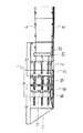
オープンシールド工法は開削工法(オープンカット工法)とシールド工法の長所を活かした合理性に富む工法であり、このオープンシールド工法で使用するオープンシールド機1の概略は図11に示すように左右の側壁板1aと、これら側壁板1aに連結する底板1bとからなる前面、後面および上面を開口したもので、前記側壁板1aと底板1bの先端を刃口11として形成し、また側壁板1aの中央または後端近くにシールドジャッキ2を後方に向け上下に並べて配設する。図中3は隔壁を示す。
The open shield method is a rational method that utilizes the advantages of the open cut method (open cut method) and the shield method, and the outline of the open shield machine 1 used in this open shield method is as shown in FIG. The front, rear, and top surfaces of the plate 1a and the
かかるオープンシールド機1を使用して施工するオープンシールド工法は、図示は省略するが、発進坑内にこのオープンシールド機1を設置して、オープンシールド機1のシールドジャッキ2を伸長して発進坑内の反力壁に反力をとってオープンシールド機1を前進させ、地下構造物を形成する第1番目のコンクリート函体4を上方から吊り降ろし、オープンシールド機1のテール部1c内で縮めたシールドジャッキ2の後方にセットする。シールドジャッキ2と反力壁との間にはストラットを配設して適宜間隔調整をする。
The open shield method to be constructed using the open shield machine 1 is not shown in the figure, but the open shield machine 1 is installed in the start pit, the
また、発進坑は土留壁で構成し、オープンシールド機1を発進させるにはこの土留壁を一部鏡切りするが、必要に応じて薬液注入などで発進坑の前方部分に地盤改良を施しておくこともある。 In addition, the start pit is made up of a retaining wall, and in order to start the open shield machine 1, a part of this retaining wall is mirror-cut. If necessary, the ground is improved at the front part of the starting pit by chemical injection or the like. Sometimes it is left.
ショベル等の掘削機9でオープンシールド機1の前面または上面から土砂を掘削しかつ排土する。この排土工程と同時またはその後にシールドジャッキ2を伸長してオープンシールド機1を前進させる。この前進工程の場合、コンクリート函体4の前にはボックス鋼材または型鋼を用いた枠体よりなるプレスバー8を配設し、オープンシールド機1は後方にセットされたコンクリート函体4から反力をとる。
そして第1番目のコンクリート函体4の前に第2番目のコンクリート函体4をオープンシールド機1のテール部1c内で吊り降ろす。以下、同様の排土工程、前進工程、コンクリート函体4のセット工程を適宜繰り返して、順次コンクリート函体4をオープンシールド機1の前進に伴い縦列に地中に残置し、さらにこのコンクリート函体4の上面に埋戻土5を入れる。
Then, the
なお、コンクリート函体4をオープンシールド機1のテール部1c内に吊り降ろす際には、コンクリートブロック等による高さ調整材7をコンクリート函体4下に配設し、このテール部1c内でオープンシールド機1の内側からコンクリート函体4の底部下方の底板1bとの隙間に裏込注入材6を一次注入し、さらに、オープンシールド機1を前進させ、底板1bが前進した後にここに形成される隙間とコンクリート函体4の左右にさらに裏込注入材6を二次注入して、裏込注入材の充填が終了する。
When the
このようにして、オープンシールド機1が到達坑まで達したならばこれを撤去して工事を完了する。 In this way, if the open shield machine 1 reaches the reaching mine, it is removed and the construction is completed.
このようなオープンシールド工法では、前記のごとくコンクリート函体4をオープンシールド機1の前進に伴い縦列に地中に残置し、コンクリート函体4は、オープンシールド機1のテール部1c内に吊り降ろされ、オープンシールド機1の前進とともに該テール部1cから出て地中に残されていくものであり、オープンシールド機1はこのように地中に残置したコンクリート函体4に反力をとって前進する。
In such an open shield construction method, as described above, the
コンクリート函体4は鉄筋コンクリート製で、図13に示すように左側板4a、右側板4bと上床板4cと下床板4dとからなるもので、前後面を開口10として開放されている。
The
ところで、下記特許文献に示すように、オープンシールド機1の機体を前後方向に複数に分割(2分割)して方向修正可能として曲線施工に対応できるようにすることもおこなわれ、図13に示すように、刃口11を先端に有するフロント部1dと、ミドル部1eおよびコンクリート函体4が吊り降ろされるテール部1cとの2つに分割する。
コンクリート函体4が吊降ろされるテール部1cの前部のミドル部1eの左右位置にシールドジャッキ2を配設するもので、ミドル部1eの前方のフロント部1dの後部の左右位置に中折れジャッキ14を配設し、左右の中折れジャッキ14のストローク差を変えることで、シールドジャッキ2でオープンシールド機1を前進させている。
A
図中13はフロント部1dに配設されるスライドジャッキ、15はスライド土留板を示す。
In the figure, 13 is a slide jack disposed on the
動作を説明すると、テール部1cにコンクリート函体4を据付けるには、シールドジャッキ2を使用してオープンシールド機1をコンクリート函体4の一函体分掘進する。
To explain the operation, in order to install the
以上のようにしてテール部1c内にコンクリート函体4を吊降ろして据付け、このテール部1c内側と、据付けたコンクリート函体4の外側との隙間に裏込注入材6を一次注入する。
The
その後、さらにオープンシールド機1を前進させる。この前進により発生するテールボイド(シールド機板厚相当分)に裏込注入材6を二次注入する。
Thereafter, the open shield machine 1 is further advanced. The
ところで砂地盤は地下水位の高いもので、施工時にこの地下水位の高い砂質土層の切羽地山が崩壊し易く、施工が難しい。施工時に切羽地山の安定を保つには、補助工法としてウェルポイント等による地下水位低下工法や薬液注入工法等の地盤改良を行わなければならず、その費用が高く付き、また、オープンシールド工法で施工する前に補助工法を行う必要があることから、工期も長くなる。 By the way, the sand ground has a high groundwater level, and the sandy soil layer of the sandy soil layer with a high groundwater level easily collapses during construction, and construction is difficult. In order to maintain the stability of the face at the time of construction, it is necessary to improve the ground such as the groundwater level lowering method using well points, etc. and the chemical injection method as an auxiliary method, which is expensive, and the open shield method is used. Since it is necessary to perform an auxiliary method before construction, the construction period becomes longer.
本発明は前記従来例の不都合を解消し、オープンシールド工法において、砂層等でウェルポイント等による地下水位低下工法や地盤改良工事を行うことなく、地山の崩壊を防止でき、また、敷設函体への推進反力を低減させることができるので、函体のコストが下がり、敷設精度が向上する砂地盤対応オープンシールド工法を提供することにある。 The present invention eliminates the inconvenience of the conventional example, and in the open shield method, it is possible to prevent the collapse of the natural ground without performing the groundwater level lowering method or the ground improvement work due to the well point etc. in the sand layer, etc. The object is to provide an open shield method for sand ground that reduces the cost of the box and improves the laying accuracy.
前記目的を達成するため請求項1記載の本発明は、オープンシールド機を使用して、オープンシールド機の前面または上面開口より前方の土砂を掘削・排土する工程と、コンクリート函体を反力にしてシールド機を掘進させる工程と、シールド機のジャッキ部内で縮めたシールドジャッキの後方のテール部に新たなコンクリート函体を上方から吊り降ろしてセットする工程とを適宜繰り返して順次コンクリート函体を縦列に埋設するオープンシールド工法において、オープンシールド機は、機体をフロント部、ミドル部、テール部となる第1、第2、第3の分割体ブロックとしたもので、前端に刃口を有し、側部、隔壁が一体となり、左右側壁内側をテーパー状にして全体幅を縮径するものとし、隔壁はその最深部に設けたフロント部とミドル部間に切羽推進ジャッキを、ミドル部とテール部間に中折れジャッキを、テール部にシールドジャッキを設け、シールド機の掘進は、フロント部を前進後、ミドル部、テール部を掘進させるものとし、切羽推進ジャッキにより、フロント部を推進させて、前方地山へ差し込み、圧密させ、フロント部内をバックホウ等の掘削機にて掘削し、フロント部前進後、切羽推進ジャッキの縮小とシールドジャッキの伸長を同時に行い、ミドル部、テール部を前進させることを要旨とするものである。 In order to achieve the above-mentioned object, the present invention as claimed in claim 1 includes a step of excavating and discharging soil in front of the front or upper surface opening of the open shield machine using an open shield machine, and a reaction force to the concrete box. The process of digging the shield machine and the process of hanging and setting a new concrete box from the top to the tail part of the rear of the shield jack shrunk in the jack part of the shield machine are repeated as necessary to sequentially form the concrete box. In the open shield method embedded in a column, the open shield machine has the front, middle, and tail parts as the first, second, and third divided blocks, and has a cutting edge at the front end. , the side, partition walls come together, the left and right side walls inside shall diameter the entire width in the tapered front portion and bromide partition provided at its deepest portion A face propulsion jack is provided between the parts, a middle-folded jack is provided between the middle part and the tail part, and a shield jack is provided at the tail part. The shield machine is advanced after the front part is advanced, and then the middle part and tail part are advanced. The front part is propelled by the face propulsion jack, inserted into the front ground, and compacted, and the inside of the front part is excavated by an excavator such as a backhoe. After the front part is advanced, the face propulsion jack is reduced and the shield jack is extended. And the middle part and the tail part are advanced.
請求項1記載の本発明によれば、地下水位の高い砂質土層の切羽地山へフロント部をつねに差し込んだ状態でフロント部隔壁前面部の地山を掘削・排土し、かつ、隔壁が前方の地山へ向かって押さえ込んだ状態となるため、切羽地山の緩みはフロント部先端の地山へ及ぶことはなく、ウェルポイントや地盤改良等による地山の安定は不要となる。 According to the present invention as set forth in claim 1, the ground in the front part of the front partition wall is excavated and excavated in a state where the front part is always inserted into the face of the sandy soil layer having a high groundwater level, and the partition wall Since it is in a state where it is pressed toward the front natural ground, the loose face of the face is not extended to the natural ground at the front end of the front part, and the stability of the natural ground due to the well point or ground improvement becomes unnecessary.
また、シールド機掘進はフロント部を必ず前進後、本体(ミドル部、テール部)を推進させる為、敷設函体への推進反力が低減され、函体のコストが下がるとともに、敷設精度があがる。 Also, since shield machine excavation always advances the front part and then propels the main body (middle part and tail part), the reaction force to the laying box is reduced, and the box cost is reduced and the laying accuracy is increased. .
さらに、地下水位の高い砂質土層の切羽地山へフロント部を差し込んだ状態で隔壁前面をバックホウ等で掘削しながら、かつ、切羽推進ジャッキを伸長させてフロント部を前方の地山へさらに前方へ推進させるので、フロント部隔壁前面の掘削・排土された部分の地山は、フロント部の左右側壁内側をテーパー状にして全体幅を縮径された部分で押し込まれることになり、最深部での隔壁で地山は圧密され、フロント部内の地山は緩まずつねに安定した状態を保つことができる。 Furthermore, while excavating the front of the bulkhead with a backhoe etc. with the front part inserted into the face of the sandy soil layer with a high groundwater level, the face propulsion jack is extended to further move the front part to the front ground. Since it is propelled forward, the ground of the excavated and earthed part in front of the front bulkhead will be pushed into the part where the entire width is reduced by tapering the left and right side walls inside the front part. The natural mountain is consolidated by the bulkhead at the part, and the natural mountain in the front part is not loose and can always maintain a stable state.
請求項2記載の本発明は、シールド機の掘進は、フロント部を切羽推進ジャッキにて前方地山へ地山崩壊角45°以上で差し込み、隔壁、側部で圧密させることを要旨とするものである。
The gist of the present invention described in
請求項2記載の本発明によれば、バックホウ等により、前方の切羽地山へ差し込んだフロント部内で、フロント部内の45°崩壊線(図2のα)より隔壁側を掘削・排土する。フロント部の両側板が45°崩壊線より地山側に常に差し込んだ状態で側板と切羽地山とのラップが十分長くなり、また、側板は分割されていないので、地下水位のある砂質地盤でもフロント部は止水性が従来タイプと比較して高い。したがって、地下水の高い砂質地盤でも切羽地山が崩れなく、安定した掘削・排土が可能となる。 According to the second aspect of the present invention, the partition wall side is excavated and discharged from the 45 ° collapse line (α in FIG. 2) in the front portion by the backhoe or the like in the front portion inserted into the front face mountain. The lap between the side plate and the face hill is sufficiently long with both side plates of the front part always inserted into the natural ground side from the 45 ° collapse line, and the side plate is not divided, so even in sandy ground with underground water level The front part has higher water-stopping performance than the conventional type. Therefore, even in sandy ground with high groundwater, the Mt.
以上述べたように本発明の砂地盤対応オープンシールド工法は、砂層等でウェルポイント等の地下水低下工法や地盤改良工事を行うことなく、地山の崩壊を防止でき、また、敷設函体への推進反力を低減させることができるので、函体のコストを下がり、敷設精度が向上するものである。 As described above, the open shield method for sand ground of the present invention can prevent the collapse of natural ground without performing groundwater lowering method and ground improvement work such as well points with sand layers, etc. Since the propulsive reaction force can be reduced, the cost of the box is reduced and the laying accuracy is improved.
以下、図面について本発明の実施の形態を詳細に説明する。図1は本発明の本発明の砂地盤対応オープンシールド工法の1実施形態を示す横断平面図、図2は同上縦断側面図、図3は図2のA−A線断面図で、先に本発明で使用するオープンシールド機について説明する。 Hereinafter, embodiments of the present invention will be described in detail with reference to the drawings. 1 is a cross-sectional plan view showing an embodiment of an open shield method for sand ground according to the present invention, FIG. 2 is a longitudinal side view of the same, and FIG. 3 is a cross-sectional view taken along line AA of FIG. The open shield machine used in the invention will be described.
オープンシールド機1は、機体をフロント部1d、ミドル部1e、テール部1cとなる第1、第2、第3の分割体ブロックとし、これらを嵌合させた。
In the open shield machine 1, the airframe is made into first, second, and third divided body blocks that become the
これらフロント部1d、ミドル部1e、テール部1cからなるオープンシールド機1は全体としては、左右の側壁板と、これら側壁板に連結する底板とからなる前面、後面および上面を開口したものである。
The open shield machine 1 comprising the
フロント部1dは、先端を刃口11として形成し、また側壁板のおよび底板の中央または後端近くに切羽推進ジャッキ16の一端を軸着する。
The
この切羽推進ジャッキ16は後方に向けて上下および左右の並べて配設するもので、端部を軸着するピンジャッキであり、多端はミドル部1eの側壁板のおよび底板の先端または中央近くに軸着することで、フロント部1dとミドル部1e間に配設される。
This
フロント部1dは左右側壁内側をテーパー状にして全体幅を縮径するものとし、また、底板も先端部はテーパー状にして上昇し、そのまま平坦になるもので、奥は開口部より縮小するもので、その最深部にフロント部隔壁17を設ける。
The
前記切羽推進ジャッキ16はこのように空間が縮径するフロント部1dの内壁と外殻の間の空間を利用して設けることができる。
The
図3に示すように、ミドル部1eはフロント部1dよりも一回り小さくした先端部分をフロント部1dに挿入させ、フロント部1d側に止水ゴム18を設け、これをミドル部1eの外周に当接させるようにする。
As shown in FIG. 3, the
ミドル部1eの後半部には中折れジャッキ19を後方に向けて設け、これをテール部1cの前端に当てるようにした。中折れジャッキ19はミドル部1eとテール部1c間に配設するものとして、ミドル部1eの左右側壁に沿って間隔を存して並列させ、かつ、上下段に設け、左右いずれかのジャッキを他より長く伸ばすことで、テール部1cに対してミドル部1eを屈折させるものである。
A middle-folded
テール部1cの前端にはテール部隔壁20を設け、ミドル部1eの後半部とそこに嵌り込むテール部1cの前端間には、ワイヤーブラシ21を設ける。
A
テール部1cは、前半をジャッキ配置部、後半をコンクリート函体4が吊り降ろされる函体設置部とする。テール部1cのジャッキ配置部にはシールドジャッキ2を後方に向け上下に並べて配設した。
The
図中22はプレスバー、23は止水バーで、これらはH形鋼等の鋼材をもってなり、左右に間隔を存して直立するプレスバー22に対して、止水バー23は横に架け渡され、全体をしてコの字に枠組まれる。 In the figure, 22 is a press bar, 23 is a water stop bar, and these are made of steel such as H-shaped steel. The whole is framed in a U-shape.
プレスバー22、止水バー23はコンクリート函体4をテール部1cに吊り降ろした際にその前端にクレーン等で吊り降ろして配置するもので、プレスバー22はシールドジャッキ2の押し圧を受ける役割をなす。
The
次に、以上のようなオープンシールド機1を用いて行う本発明の砂地盤対応オープンシールド工法について説明する。図5〜図7は本発明の各工程を示す横断平面図、図8〜図10は同上横断平面図で、まず、図5、図8に示すように函体据付、一次注入を行う。 Next, the sand shield corresponding open sand construction method of the present invention performed using the above open shield machine 1 will be described. 5 to 7 are cross-sectional plan views showing the respective steps of the present invention, and FIGS. 8 to 10 are cross-sectional plan views of the same. First, as shown in FIGS. 5 and 8, box installation and primary injection are performed.
オープンシールド機1は、既設のコンクリート函体4を反力に前進させた後であり、コンクリート函体4をテール部1cに吊り降ろし、テール部1c内でオープンシールド機1の内側からコンクリート函体4の底部下方の底板との隙間に裏込注入材6を一次注入する。
The open shield machine 1 is after the existing
次いで、切羽推進ジャッキ16により、フロント部1dを推進させる。この切羽推進ジャッキ16によるフロント部1dの前進は、フロント部隔壁17で土砂を圧密することになる。
Next, the
このフロント部1dの前進は、切羽推進ジャッキ16にて前方地山へ地山崩壊角45°以上で差し込み、隔壁、側部で圧密させる。
The
そして、フロント部1dにて防護された切羽内をバックホウ等の掘削機9にて掘削する。(図4参照)
Then, the inside of the face protected by the
次いで、切羽推進ジャッキ16の縮小とシールドジャッキ2の伸長を同時に行い、ミドル部1e、テール部1cを掘進させる。縦列させたコンクリート函体4を反力にして、シールドジャッキ2でミドル部1eとテール部1cとを一緒に推進させるものである。
Next, the reduction of the
このミドル部1eとテール部1cとの前進は、このように同時に行う場合の他、ミドル部1eを中折れジャッキ19によりまず、前進させ、次いで、テール部1cをシールドジャッキ2で前進させるように、2段階に分けてもよい。
The
なお、曲線施工の場合は、中折れジャッキ19により、テール部1cに対してミドル部1eを屈折させることにより対処する。
In the case of curved construction, the
以降、以上の掘進作業を繰り返し行い、1函体分掘進終了後、初めの工程に戻る。 Thereafter, the above excavation work is repeated, and after completion of excavation for one box, the process returns to the first step.
1 オープンシールド機 1a 側壁板
1b 底板 1c テール部
1d フロント部 1e ミドル部
2 シールドジャッキ 3 隔壁
4 コンクリート函体 4a 左側板
4b 右側板 4c 上床板
4d 下床板 5 埋戻土
6 裏込注入材 7 高さ調整材
8 プレスバー 9 掘削機
10 開口 11 刃口
12 テール部側板 13 スライドジャッキ
14 中折れジャッキ 15 スライド土留板
16 切羽推進ジャッキ 17 フロント部隔壁
18 止水ゴム 19 中折れジャッキ
20 テール部隔壁 21 ワイヤーブラシ
22 プレスバー 23 止水バー
DESCRIPTION OF SYMBOLS 1 Open shield machine 1a
Claims (2)
オープンシールド機は、機体をフロント部、ミドル部、テール部となる第1、第2、第3の分割体ブロックとしたもので、
前端に刃口を有し、側部、隔壁が一体となり、左右側壁内側をテーパー状にして全体幅を縮径するものとし、隔壁はその最深部に設けたフロント部とミドル部間に切羽推進ジャッキを、ミドル部とテール部間に中折れジャッキを、テール部にシールドジャッキを設け、
シールド機の掘進は、フロント部を前進後、ミドル部、テール部を掘進させるものとし、
切羽推進ジャッキにより、フロント部を推進させて、前方地山へ差し込み、圧密させ、フロント部内をバックホウ等の掘削機にて掘削し、フロント部前進後、切羽推進ジャッキの縮小とシールドジャッキの伸長を同時に行い、ミドル部、テール部を前進させることを特徴とした砂地盤対応オープンシールド工法。 Using an open shield machine, the process of excavating and discharging the soil in front of the front or top opening of the open shield machine, the process of digging the shield machine using the reaction force of the concrete box, and the jack part of the shield machine In the open shield method of burying concrete boxes in series one after another by repeating the process of hanging and setting a new concrete box from the top to the tail part behind the shield jack shrunk in
The open shield machine is the first, second, and third divided body blocks that become the front part, middle part, and tail part.
It has a cutting edge at the front end, and the side and partition walls are integrated, and the inside of the left and right side walls is tapered to reduce the overall width. The partition wall is propelled between the front part and middle part provided at the deepest part. The jack is folded between the middle part and the tail part, and the shield part is provided on the tail part.
In the shield machine, the middle part and the tail part are dug after moving forward in the front part.
With the face propulsion jack, the front part is propelled, inserted into the front ground, consolidated, and the inside of the front part is excavated with an excavator such as a backhoe, and after moving forward, the face propulsion jack is reduced and the shield jack is extended. Open shield construction method for sand ground, which is performed simultaneously and the middle part and tail part are advanced.
Priority Applications (1)
| Application Number | Priority Date | Filing Date | Title |
|---|---|---|---|
| JP2012090939A JP5491562B2 (en) | 2012-04-12 | 2012-04-12 | Open shield construction method for sand ground |
Applications Claiming Priority (1)
| Application Number | Priority Date | Filing Date | Title |
|---|---|---|---|
| JP2012090939A JP5491562B2 (en) | 2012-04-12 | 2012-04-12 | Open shield construction method for sand ground |
Publications (2)
| Publication Number | Publication Date |
|---|---|
| JP2013217161A JP2013217161A (en) | 2013-10-24 |
| JP5491562B2 true JP5491562B2 (en) | 2014-05-14 |
Family
ID=49589579
Family Applications (1)
| Application Number | Title | Priority Date | Filing Date |
|---|---|---|---|
| JP2012090939A Active JP5491562B2 (en) | 2012-04-12 | 2012-04-12 | Open shield construction method for sand ground |
Country Status (1)
| Country | Link |
|---|---|
| JP (1) | JP5491562B2 (en) |
Families Citing this family (2)
| Publication number | Priority date | Publication date | Assignee | Title |
|---|---|---|---|---|
| JP6104991B2 (en) * | 2015-06-30 | 2017-03-29 | 植村 誠 | Open shield machine |
| CN112963159B (en) * | 2021-01-21 | 2023-02-28 | 中铁十六局集团有限公司 | Operation method of ground-in shield model test reaction frame device with continuous propelling capability |
Family Cites Families (2)
| Publication number | Priority date | Publication date | Assignee | Title |
|---|---|---|---|---|
| JP4234752B2 (en) * | 2006-11-22 | 2009-03-04 | 誠 植村 | Open shield machine and open shield method |
| JP4436401B2 (en) * | 2007-11-02 | 2010-03-24 | 誠 植村 | Open shield method and open shield machine |
-
2012
- 2012-04-12 JP JP2012090939A patent/JP5491562B2/en active Active
Also Published As
| Publication number | Publication date |
|---|---|
| JP2013217161A (en) | 2013-10-24 |
Similar Documents
| Publication | Publication Date | Title |
|---|---|---|
| JP5781574B2 (en) | Starting reaction device for open shield machine | |
| JP5155237B2 (en) | Open shield machine and open shield method using this open shield machine | |
| JP5204063B2 (en) | Box foundation construction method in open shield method | |
| JP5491562B2 (en) | Open shield construction method for sand ground | |
| JP6194388B1 (en) | Open shield method | |
| JP4205123B2 (en) | Open shield machine | |
| JP6307136B2 (en) | Open shield method | |
| JP6034447B1 (en) | Open shield method | |
| JP2010248724A (en) | Open shield machine | |
| JP4520496B2 (en) | Open shield machine | |
| JP4148047B2 (en) | Open shield machine | |
| JP7025375B2 (en) | Open shield machine | |
| JP7061959B2 (en) | Open shield machine | |
| JP5639213B2 (en) | Open shield method | |
| JP5081858B2 (en) | Open shield machine | |
| JP4279441B2 (en) | Open shield machine and open shield method using this open shield machine | |
| JP3923973B2 (en) | Open shield machine | |
| JP3766423B2 (en) | Retaining wall construction method | |
| JP2005307544A (en) | Laying method and removal method for covering plate for open shield method | |
| JP3868959B2 (en) | Waterway construction method | |
| JP7384956B2 (en) | Open shield method and open shield machine | |
| JP4279818B2 (en) | Open shield method | |
| JP5389869B2 (en) | Open shield method | |
| JP5015809B2 (en) | Open shield machine | |
| JP2657733B2 (en) | Open shield method and open shield machine |
Legal Events
| Date | Code | Title | Description |
|---|---|---|---|
| A131 | Notification of reasons for refusal |
Free format text: JAPANESE INTERMEDIATE CODE: A131 Effective date: 20130820 |
|
| A521 | Request for written amendment filed |
Free format text: JAPANESE INTERMEDIATE CODE: A523 Effective date: 20131016 |
|
| TRDD | Decision of grant or rejection written | ||
| A01 | Written decision to grant a patent or to grant a registration (utility model) |
Free format text: JAPANESE INTERMEDIATE CODE: A01 Effective date: 20140225 |
|
| A61 | First payment of annual fees (during grant procedure) |
Free format text: JAPANESE INTERMEDIATE CODE: A61 Effective date: 20140227 |
|
| R150 | Certificate of patent or registration of utility model |
Ref document number: 5491562 Country of ref document: JP Free format text: JAPANESE INTERMEDIATE CODE: R150 |
|
| R250 | Receipt of annual fees |
Free format text: JAPANESE INTERMEDIATE CODE: R250 |
|
| R250 | Receipt of annual fees |
Free format text: JAPANESE INTERMEDIATE CODE: R250 |
|
| R250 | Receipt of annual fees |
Free format text: JAPANESE INTERMEDIATE CODE: R250 |
|
| R250 | Receipt of annual fees |
Free format text: JAPANESE INTERMEDIATE CODE: R250 |
|
| R250 | Receipt of annual fees |
Free format text: JAPANESE INTERMEDIATE CODE: R250 |
|
| R250 | Receipt of annual fees |
Free format text: JAPANESE INTERMEDIATE CODE: R250 |
|
| R250 | Receipt of annual fees |
Free format text: JAPANESE INTERMEDIATE CODE: R250 |
|
| R250 | Receipt of annual fees |
Free format text: JAPANESE INTERMEDIATE CODE: R250 |