JP7007943B2 - Lens drive device with vibration wave motor and vibration wave motor - Google Patents
Lens drive device with vibration wave motor and vibration wave motor Download PDFInfo
- Publication number
- JP7007943B2 JP7007943B2 JP2018020884A JP2018020884A JP7007943B2 JP 7007943 B2 JP7007943 B2 JP 7007943B2 JP 2018020884 A JP2018020884 A JP 2018020884A JP 2018020884 A JP2018020884 A JP 2018020884A JP 7007943 B2 JP7007943 B2 JP 7007943B2
- Authority
- JP
- Japan
- Prior art keywords
- vibrator
- friction member
- wave motor
- pressurizing
- vibration wave
- Prior art date
- Legal status (The legal status is an assumption and is not a legal conclusion. Google has not performed a legal analysis and makes no representation as to the accuracy of the status listed.)
- Active
Links
- 230000001105 regulatory effect Effects 0.000 claims description 67
- 238000005096 rolling process Methods 0.000 claims description 35
- 230000005540 biological transmission Effects 0.000 description 40
- 230000000903 blocking effect Effects 0.000 description 9
- 230000006378 damage Effects 0.000 description 6
- 239000000470 constituent Substances 0.000 description 5
- ORQBXQOJMQIAOY-UHFFFAOYSA-N nobelium Chemical compound [No] ORQBXQOJMQIAOY-UHFFFAOYSA-N 0.000 description 4
- 239000000853 adhesive Substances 0.000 description 2
- 230000001070 adhesive effect Effects 0.000 description 2
- 238000001514 detection method Methods 0.000 description 2
- 230000006835 compression Effects 0.000 description 1
- 238000007906 compression Methods 0.000 description 1
- 238000010586 diagram Methods 0.000 description 1
- 230000000694 effects Effects 0.000 description 1
- 238000000605 extraction Methods 0.000 description 1
- 239000000835 fiber Substances 0.000 description 1
- CNQCVBJFEGMYDW-UHFFFAOYSA-N lawrencium atom Chemical compound [Lr] CNQCVBJFEGMYDW-UHFFFAOYSA-N 0.000 description 1
Images


Classifications
-
- G—PHYSICS
- G02—OPTICS
- G02B—OPTICAL ELEMENTS, SYSTEMS OR APPARATUS
- G02B7/00—Mountings, adjusting means, or light-tight connections, for optical elements
- G02B7/02—Mountings, adjusting means, or light-tight connections, for optical elements for lenses
- G02B7/04—Mountings, adjusting means, or light-tight connections, for optical elements for lenses with mechanism for focusing or varying magnification
- G02B7/08—Mountings, adjusting means, or light-tight connections, for optical elements for lenses with mechanism for focusing or varying magnification adapted to co-operate with a remote control mechanism
-
- G—PHYSICS
- G02—OPTICS
- G02B—OPTICAL ELEMENTS, SYSTEMS OR APPARATUS
- G02B7/00—Mountings, adjusting means, or light-tight connections, for optical elements
- G02B7/02—Mountings, adjusting means, or light-tight connections, for optical elements for lenses
- G02B7/04—Mountings, adjusting means, or light-tight connections, for optical elements for lenses with mechanism for focusing or varying magnification
-
- G—PHYSICS
- G03—PHOTOGRAPHY; CINEMATOGRAPHY; ANALOGOUS TECHNIQUES USING WAVES OTHER THAN OPTICAL WAVES; ELECTROGRAPHY; HOLOGRAPHY
- G03B—APPARATUS OR ARRANGEMENTS FOR TAKING PHOTOGRAPHS OR FOR PROJECTING OR VIEWING THEM; APPARATUS OR ARRANGEMENTS EMPLOYING ANALOGOUS TECHNIQUES USING WAVES OTHER THAN OPTICAL WAVES; ACCESSORIES THEREFOR
- G03B13/00—Viewfinders; Focusing aids for cameras; Means for focusing for cameras; Autofocus systems for cameras
- G03B13/32—Means for focusing
- G03B13/34—Power focusing
-
- H—ELECTRICITY
- H02—GENERATION; CONVERSION OR DISTRIBUTION OF ELECTRIC POWER
- H02N—ELECTRIC MACHINES NOT OTHERWISE PROVIDED FOR
- H02N2/00—Electric machines in general using piezoelectric effect, electrostriction or magnetostriction
- H02N2/0005—Electric machines in general using piezoelectric effect, electrostriction or magnetostriction producing non-specific motion; Details common to machines covered by H02N2/02 - H02N2/16
- H02N2/001—Driving devices, e.g. vibrators
- H02N2/003—Driving devices, e.g. vibrators using longitudinal or radial modes combined with bending modes
- H02N2/004—Rectangular vibrators
-
- H—ELECTRICITY
- H02—GENERATION; CONVERSION OR DISTRIBUTION OF ELECTRIC POWER
- H02N—ELECTRIC MACHINES NOT OTHERWISE PROVIDED FOR
- H02N2/00—Electric machines in general using piezoelectric effect, electrostriction or magnetostriction
- H02N2/0005—Electric machines in general using piezoelectric effect, electrostriction or magnetostriction producing non-specific motion; Details common to machines covered by H02N2/02 - H02N2/16
- H02N2/005—Mechanical details, e.g. housings
- H02N2/0055—Supports for driving or driven bodies; Means for pressing driving body against driven body
- H02N2/006—Elastic elements, e.g. springs
-
- H—ELECTRICITY
- H02—GENERATION; CONVERSION OR DISTRIBUTION OF ELECTRIC POWER
- H02N—ELECTRIC MACHINES NOT OTHERWISE PROVIDED FOR
- H02N2/00—Electric machines in general using piezoelectric effect, electrostriction or magnetostriction
- H02N2/0005—Electric machines in general using piezoelectric effect, electrostriction or magnetostriction producing non-specific motion; Details common to machines covered by H02N2/02 - H02N2/16
- H02N2/005—Mechanical details, e.g. housings
- H02N2/0065—Friction interface
-
- H—ELECTRICITY
- H02—GENERATION; CONVERSION OR DISTRIBUTION OF ELECTRIC POWER
- H02N—ELECTRIC MACHINES NOT OTHERWISE PROVIDED FOR
- H02N2/00—Electric machines in general using piezoelectric effect, electrostriction or magnetostriction
- H02N2/02—Electric machines in general using piezoelectric effect, electrostriction or magnetostriction producing linear motion, e.g. actuators; Linear positioners ; Linear motors
- H02N2/026—Electric machines in general using piezoelectric effect, electrostriction or magnetostriction producing linear motion, e.g. actuators; Linear positioners ; Linear motors by pressing one or more vibrators against the driven body
-
- H—ELECTRICITY
- H02—GENERATION; CONVERSION OR DISTRIBUTION OF ELECTRIC POWER
- H02N—ELECTRIC MACHINES NOT OTHERWISE PROVIDED FOR
- H02N2/00—Electric machines in general using piezoelectric effect, electrostriction or magnetostriction
- H02N2/02—Electric machines in general using piezoelectric effect, electrostriction or magnetostriction producing linear motion, e.g. actuators; Linear positioners ; Linear motors
- H02N2/04—Constructional details
Description
本発明は、振動波モータ及び振動波モータを備えたレンズ駆動装置に関する。 The present invention relates to a vibration wave motor and a lens driving device including a vibration wave motor.
特許文献1で開示された駆動装置は、防振機構に適用されているため2軸で撮像素子を駆動しているが、1軸のみの構成に着目すると、振動子と摺動板を押圧機構で挟持し、摺動板側にはボールを配置した構成とすることで動力を取り出している。
Since the drive device disclosed in
しかしながら特許文献1で開示された駆動装置では、衝撃力により押圧機構の反押圧方向に力が働いた場合、振動子、摺動板、ボールが押圧方向に変位することで脱落してしまう。特に摺動板の重量は比較的重く、落下衝撃等により数100~数1000Gの力が発生した場合には、振動子へのダメージは深刻であり、破壊の危険性は高まる。
However, in the drive device disclosed in
本発明の目的は、構成部材の脱落を防止した振動波モータを提供する。 An object of the present invention is to provide a vibration wave motor that prevents the constituent members from falling off.
上記目的を達成するために、振動波モータは、振動体と圧電素子とを備えた振動子と、摩擦部材と、前記振動子と前記摩擦部材とを接触させる方向に加圧する加圧手段と、を備え、前記振動子に発生する振動により前記振動子と前記摩擦部材とを前記加圧手段の加圧方向と直交する方向に相対移動させ、前記振動子及び前記摩擦部材は、前記振動子と前記摩擦部材との前記相対移動の方向への移動に伴って移動しない固定部材に対して、前記加圧方向と平行な方向に移動可能であり、前記加圧方向と平行な方向における前記摩擦部材の移動可能量が前記加圧方向と平行な方向における前記振動子の移動可能量より小さくなるように、前記摩擦部材の前記移動可能量を規制する第1の規制手段と前記振動子の前記移動可能量を規制する第2の規制手段とを備えることを特徴とする。
In order to achieve the above object, the vibration wave motor is a pressurizing means for pressurizing a vibrator provided with a vibrating body and a piezoelectric element, a friction member, and a direction in which the vibrator and the friction member are brought into contact with each other. And , the vibration generated in the vibrator causes the vibrator and the friction member to move relative to each other in a direction orthogonal to the pressurizing direction of the pressurizing means, and the vibrator and the friction member move in a direction orthogonal to the pressurizing direction of the pressurizing means. The fixed member that does not move with the movement of the child and the friction member in the relative movement direction can move in a direction parallel to the pressurization direction , and the said in a direction parallel to the pressurization direction. The first regulating means for regulating the movable amount of the friction member and the vibrator so that the movable amount of the friction member is smaller than the movable amount of the vibrator in the direction parallel to the pressurizing direction. It is characterized by comprising a second regulating means for regulating the movable amount of the above .
本発明によれば、構成部材の脱落を防止した振動波モータを提供することができる。 According to the present invention, it is possible to provide a vibration wave motor that prevents the constituent members from falling off.
(実施例1)
以下に、本発明の実施例1を添付の図1~3に基づいて詳細に説明する。図面において、相対移動の方向をX方向、加圧方向をZ方向、X方向、Z方向のいずれにも直交する方向をY方向と定義する。
(Example 1)
Hereinafter, Example 1 of the present invention will be described in detail with reference to FIGS. 1 to 3 attached. In the drawings, the direction of relative movement is defined as the X direction, the pressurizing direction is defined as the Z direction, and the direction orthogonal to any of the X direction and the Z direction is defined as the Y direction.
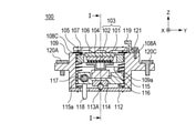
図1は、本発明の実施例1における振動波モータ100を図2の断面線I-Iに沿って断面にした要部断面図である。図2は、振動波モータ100を図1の断面線II-IIに沿って断面にした要部断面図である。図3は、振動波モータ100の構成を模式的に示した分解図である。
FIG. 1 is a cross-sectional view of a main part of the
振動波モータ100(超音波モータ)は、振動体101と圧電素子102で構成される振動子103を備える。振動体101と圧電素子102は、接着剤等の手段により固着され、振動体101は、2つの突起部を備え、後述する摩擦部材116に摩擦接触している。図2においてはそのうち1つの突起部のみが示されている。
The vibration wave motor 100 (ultrasonic motor) includes a
振動子保持部材105は、振動子103の全体を保持している。振動遮断部材104は、圧電素子102のZ方向の上部に配置され、振動子103で発生する振動が振動遮断部材104のZ方向の上部に設けられた他の部材へ伝達するのを防止している。なお、振動遮断部材104としては、フェルトなどの繊維からなる部材が用いられることが多い。
The
加圧力を伝達する第1の伝達部材106及び第2の伝達部材107は、振動遮断部材104のZ方向の上部に配置される。加圧バネ108A、108B、108C、108Dは、振動子103を摩擦部材116へ加圧するための加圧力を発生し、本実施例1では4つの引っ張りコイルバネにより構成されている。この4つの引っ張りコイルバネは、紙面奥行方向(Y方向)に並んで配置されるため、図1では加圧バネ108A、108Bのみが示される。なお、第1の伝達部材106、第2の伝達部材107と加圧バネ108A、108B、108C、108Dは、請求項の記載における加圧手段に対応している。
The
保持部材109は、振動子保持部材105を保持する部材であって、保持部材109と振動子保持部材105との間には、転動コロ110A、110Bとガタ寄せバネ111が備えられている。このような構成によって、保持部材109と振動子保持部材105は、X方向にガタなく連結されるとともに、振動子保持部材105は保持部材109に対してZ方向に移動可能に保持されている。すなわち、振動子103を保持する振動子保持部材105が保持部材109に保持されることにより、振動子103は保持部材109に保持される。そして、保持部材109には、3つのネジ部材120A、120B、120Cが係合する孔が設けられ、不図示の筐体にこれら3つのネジ部材120A、120B、120Cにより保持部材109が固定されている。また、保持部材109には、落下等の衝撃力による摩擦部材116のZ方向の移動を規制する規制部109a、109bが備えられている。なお、規制部109a、109bは、請求項の記載における第1の規制手段に対応している。
The
固定側案内部材112は、2つの転動ボール113A、113B(転動部材)を保持するガイド溝112a、112bを備えるとともに、保持部材109に連結されている。可動側案内部材114は、2つの転動ボール113A、113Bを保持するガイド溝114a、114bを備える。2つの転動ボール113A、113Bは、加圧バネ108A、108B、108C、108Dの加圧力により固定側案内部材112と可動側案内部材114で挟持されている。
The fixed-
摩擦部材保持部材115は、可動側案内部材114と摩擦部材116を保持する。更に摩擦部材保持部材115は、Y方向に延びた長穴部115aを備え、この長穴部115a内には、棒状のガイド部材117がX方向に伸延して配置され、長穴部115aの内部で摩擦部材保持部材115とZ方向で遊嵌している。ガイド部材117は、摩擦部材116を保持する摩擦部材保持部材115をX方向に案内し、振動波モータ100の外側に設けられた不図示の筐体によりその両端が保持されている。摩擦部材116は、Z方向の上面側に振動子103と接触する摩擦接触面を備え、下面側は摩擦部材保持部材115に固定されている。すなわち、振動子103及び摩擦部材116は、保持部材109に対して略加圧方向に移動可能に構成されている。
The friction
上記の構成により、可動側案内部材114と摩擦部材保持部材115と摩擦部材116は、一体となった状態で、固定側案内部材112に対して転動ボール113A、113BによりX方向に移動可能に案内される。更に、X方向に平行で転動ボール113A、113Bの中心付近を通過する軸を中心にする回転を規制するガイド部材117が摩擦部材保持部材115の延びた長穴部115aに遊嵌している。そのため、可動側案内部材114と摩擦部材保持部材115と摩擦部材116を安定してX方向に直線駆動することが可能となっている。
With the above configuration, the movable
振動波モータ100は、動力取り出し部118を備えており、この動力取り出し部118に駆動対象となる被駆動部材が連結されることで、被駆動部材の直線駆動が可能となる。更に振動波モータ100は、ネジ部材121により保持部材109に固定された規制部材119を備えており、規制部材119は、落下等の衝撃力による振動子103のZ方向の移動を規制している。なお、規制部材119は、請求項の記載における第2の規制手段に対応している。
The
以上のように本発明の振動波モータ100は構成され、振動子103に発生する高周波振動(超音波領域の周波数の高周波振動)により摩擦部材116をX方向へ相対移動させることで直線駆動を実現している。本実施例1では、摩擦部材116が移動し、振動子103が固定されている。なお、実際には振動子103の圧電素子102には駆動電圧を供給するためのフレキシブルプリント基板と、駆動電圧を発生する駆動回路が存在するが、図示及び説明を省略している。
As described above, the
ところで、振動波モータ100に落下等による衝撃力が加わり、加圧手段による加圧力以上の力が加圧バネ108A、108B、108C、108Dを引き延ばす方向に発生した場合について考えてみる。例えば、図2において、衝撃力により摩擦部材116がガイド部材117を中心に回転し、振動子103がZ方向へ押し上げられると、転動ボール113A、113Bがガイド溝112a、112b、114a、114bから脱落する恐れがある。また、加圧バネ108A、108B、108C、108Dが引き伸ばされて塑性変形する危険性が生じる。
By the way, consider a case where an impact force due to a drop or the like is applied to the
しかしながら、振動波モータ100には、振動子103と摩擦部材116のZ方向への移動を規制する規制部材119が設けられており、構成部材の脱落が防止されている。一方、振動子103と摩擦部材116の衝突により振動子103が破損する危険性については、本発明では規制部109a、109bが設けられている。これらの規制部109a、109b、規制部材119に当接する部材のクリアランスを工夫することで、衝撃力による上記破損を回避している。以下詳細を説明する。
However, the
図4(A)、(B)は、図2と同様に振動波モータ100の要部断面図である。図4(A)は、落下等により弱い衝撃力が加わった第1の状態を、図4(B)は落下等により強い衝撃力が加わった第2の状態をそれぞれ示す。なお、図において不図示である部材等には括弧を付して記載する。図4(A)において、可動側案内部材114、摩擦部材保持部材115、摩擦部材116は一体となってガイド部材117を中心に反時計回り(CCW)に回転し、摩擦部材保持部材115が規制部109a(109b)と当接している。したがって、規制部109a(109b)により摩擦部材116のZ方向の移動が規制されている。このとき、転動ボール113A、113Bの脱落を防止するための摩擦部材116と規制部109a(109b)とのZ方向の間隙は、ガイド溝112a、112b、114a、114bへの転動ボール113A、113Bの嵌入量に基づいて決められている。
4 (A) and 4 (B) are cross-sectional views of a main part of the
そして、摩擦部材116の回転により、Z方向の上部に配置された振動子103、振動遮断部材104、振動子保持部材105、第1の伝達部材106、第2の伝達部材107は一体となってZ方向に移動している。しかしながら、図4(A)においては、規制部材119と第2の伝達部材107は接触しておらず、Z方向のクリアランスCを隔てている。なお、振動子103には加圧バネ108A、108B、108C、108Dによる加圧力以外の力は働いていない。また、厳密にはバネが伸びることにより加圧力は増加するが、衝撃力と比較すると十分に小さいためその増加は無視している。
Then, due to the rotation of the
図4(B)は、図4(A)より更に強い衝撃力が加わった第2の状態を示す。可動側案内部材114、摩擦部材保持部材115、摩擦部材116は、図4(A)と同様に一体となってガイド部材117を中心に反時計回り(CCW)に回転し、摩擦部材保持部材115が規制部109a、109bに当接する。したがって、規制部109a、109bにより摩擦部材116のZ方向の移動が規制される。一方、摩擦部材116のZ方向の上部に配置された振動子103、振動遮断部材104、振動子保持部材105、第1の伝達部材106、第2の伝達部材107が一体となってZ方向に移動し、第2の伝達部材107が規制部材119に当接している。したがって、規制部材119により振動子103のZ方向の移動が規制されている。このとき、振動子103は摩擦部材116に接触していないため、振動子103が衝撃力により摩擦部材116と衝突して破損することを防止できる。
FIG. 4B shows a second state in which a stronger impact force is applied than in FIG. 4A. The movable
そして、図2で示した通常状態における摩擦部材116の位置を点線116’で示すと、規制部材119により規制された際の振動子103のZ方向の移動は移動量D1となる。また、規制部109a、109bにより規制された際の摩擦部材116のZ方向の移動は移動量D2となる。このとき、移動量D1と移動量D2が下記の式(1)の大小関係となるように規制部109a、109b、規制部材119のZ方向の寸法が設定される。また、振動子103と摩擦部材116の間には、間隙(D1-D2)が生じている。
D1>D2 (1)
When the position of the
D1> D2 (1)
式(1)の大小関係により、振動子103と摩擦部材116は、強い衝撃力が加わった際には、接触せずに離間することとなる。これにより、振動子103が摩擦部材116に衝突しその際の衝撃力により破損することを防止している。また、加圧バネ108A、108B、108C、108Dは、Z方向に伸ばされるが規制部材119が設けられているため、塑性変形が防止されるとともに、加圧バネ108A、108B、108C、108Dが外れることがない。更に規制部109a、109bにより規制された際の摩擦部材116の移動量D2は、転動ボール113A、113Bの直径より小さいため、摩擦部材116が移動しても転動ボール113A、113Bが脱落することがない。
Due to the magnitude relationship of the equation (1), the
以上のような構成により、実施例1では、振動波モータ100に衝撃力が加わった場合でも、構成部材の脱落と振動子103へのダメージを防止することができるので、良好なモータ性能を維持することが可能となる。
With the above configuration, in the first embodiment, even when an impact force is applied to the
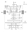
(実施例2)
実施例2は、実施例1とは異なり、第1の振動子203A、第2の振動子203Bの2つを備えており、高推力タイプの振動波モータ200となっている。なお、実施例1と同様な構成については、詳細な説明を省略する。また、第1の振動子203Aの構成と同様な構成を有する第2の振動子203B及びこれに関係する部材については括弧書きで示し、その詳細な説明を省略する。なお、図において不図示である部材等には括弧を付して記載する。
(Example 2)
Unlike the first embodiment, the second embodiment includes two
図5は、本発明の実施例2における振動波モータ200をY方向に沿って断面にした要部断面図である。上記のように振動波モータ200は、第1の振動子203A、第2の振動子203Bの2つを備えており、それぞれに対応するように各部材が備えられている。第1の振動子203Aは、振動体201Aと圧電素子202Aで構成されている。振動体201Aと圧電素子202Aは、接着剤等の手段により固着され、実施例1と同様に2つの突起部を備え、摩擦部材216Aに摩擦接触している。図5においてはそのうち1つの突起部のみが示されている。第2の振動子203Bの構成も第1の振動子203Aと同様である。
FIG. 5 is a cross-sectional view of a main part of the
振動子保持部材205Aは、第1の振動子203Aの全体を保持している。振動遮断部材204Aは、圧電素子202AのZ方向の上部に配置され、第1の振動子203Aで発生する振動が振動遮断部材204AのZ方向の上部に設けられた他の部材へ伝達するのを防止している。
The
加圧力を伝達する第1の伝達部材206A(206B)、第2の伝達部材207A(207B)、第3の伝達部材219A(219B)及び転動ボール220A、220B、220C、220Dは、振動遮断部材204A(204B)のZ方向の上部に配置される。加圧バネ208A、208B、208C、208Dは、本実施例2では4つの圧縮コイルバネにより構成され、紙面奥行方向(X方向)に並んで配置されるため加圧バネ208A、208Bのみが示される。また、転動ボール220A、220B、220C、220Dも、紙面奥行方向(X方向)に並んで配置されるため転動ボール220A、220Bのみが示されている。
The
加圧バネ208A~208DのZ方向のバネ力により、第2の伝達部材207A(207B)は、転動ボール220A~220Dを支点として回転することが可能である。一方、第2の伝達部材207A(207B)は、第1の伝達部材206A(206B)に備えられたZ方向に突出する当接部と当接し、この当接部を介してバネ力を伝達し、第1の振動子203A(203B)を摩擦部材216A(216B)に摩擦接触させる。なお、第1の伝達部材206A(206B)、第2の伝達部材207A(207B)、第3の伝達部材219A(219B)、加圧バネ208A~208Dと転動ボール220A~220Dは、請求項の記載における加圧手段に対応している。
Due to the spring force in the Z direction of the pressure springs 208A to 208D, the
保持部材209は、振動子保持部材205A(205B)を保持する部材であって、保持部材209と振動子保持部材205A(205B)との間には、転動コロ(不図示)とガタ寄せバネ(不図示)が備えられている。このような構成によって、保持部材209と振動子保持部材205A(205B)は、X方向にガタなく連結されるとともに、振動子保持部材205A(205B)は保持部材209に対してZ方向に移動可能に保持されている。また、保持部材209には、落下等の衝撃力による摩擦部材216A(216B)のZ方向の移動を規制する規制部209a、209bが備えられている。規制部209a、209bは図5の紙面奥行方向(X方向)に配置されるため、規制部209aのみが示されている。なお、規制部209a、209bは、請求項の記載における第1の規制手段に対応している。
The holding
更に保持部材209には、落下等の衝撃力による第1の振動子203A(203B)のZ方向の移動を規制する規制部209c、209dが備えられている。規制部209c、209dは、請求項の記載における第2の規制手段に対応している。第1の振動子203A(203B)及び摩擦部材216A(216B)の働きの規制については後ほど詳細に説明する。
Further, the holding
摩擦部材保持部材215は、可動側案内部材214と摩擦部材216A(216B)を保持する。更に摩擦部材保持部材215は、Y方向に延びた長穴部215aを備え、この長穴部215aには、棒状のガイド部材217がX方向に伸延して配置され、長穴部215aの内部で摩擦部材保持部材215とZ方向で遊嵌している。ガイド部材217は、摩擦部材216A(216B)を保持する摩擦部材保持部材215をX方向に案内し、振動波モータ200の外側に設けられた不図示の筐体によりその両端が保持されている。摩擦部材216A(216B)は、Z方向の上面側に第1の振動子203A(203B)と接触する摩擦接触面を備え、下面側は摩擦部材保持部材215に固定されている。すなわち、第1の振動子203A(203B)及び摩擦部材216A(216B)は、保持部材209に対して略加圧方向に移動可能に構成されている。
The friction
上記の構成により、可動側案内部材214と摩擦部材保持部材215と摩擦部材216A(216B)は、一体となった状態で、固定側案内部材212に対して転動ボール213A、213BによりX方向に移動可能に案内される。更に、X方向に平行で転動ボール213A、213Bの中心付近を通過する軸を中心にする回転を規制するガイド部材217が摩擦部材保持部材215の延びた長穴部215aに遊嵌している。そのため、可動側案内部材214と摩擦部材保持部材215と摩擦部材216A(216B)を安定してX方向に直線駆動することが可能となっている。
With the above configuration, the movable
振動波モータ200は、動力取り出し部218を備えており、この動力取り出し部218に駆動対象となる被駆動部材が連結されることで、被駆動部材の直線駆動が可能となる。第3の伝達部材219A(219B)は、第2の伝達部材207A(207B)と転動ボール220A~220Dを介して加圧バネ208A~208Dのバネ力を受ける。しかしながら、第3の伝達部材219A(219B)は、ネジ部材により保持部材209に固定されているため、第2の伝達部材207A(207B)と転動ボール220A~220DのZ方向の移動を規制する。
The
以上のように本発明の振動波モータ200は構成され、第1の振動子203A(203B)に発生する高周波振動により摩擦部材216A(216B)をX方向へ相対移動させることで直線駆動を実現している。第1の振動子203A、第2の振動子203Bの2つを備えているため、実施例1と比べて約2倍の推力を得ることができる。次に、落下等の衝撃力発生時における第1の振動子203A(203B)、摩擦部材216A(216B)の挙動について以下詳細に説明する。
As described above, the
図6は、図5と同様に振動波モータ200の要部断面図であって、落下等により衝撃力が加わった状態を示す。図6において、可動側案内部材214、摩擦部材保持部材215、摩擦部材216A(216B)は一体となってガイド部材217を中心に時計回り(CW)に回転し、摩擦部材保持部材215が規制部209a(209b)と当接する。したがって、規制部209a(209b)により摩擦部材216A(216B)のZ方向の移動が規制される。
FIG. 6 is a cross-sectional view of a main part of the
一方、摩擦部材216AのZ方向の上部に配置された第1の振動子203A、振動遮断部材204A、振動子保持部材205A、第1の伝達部材206Aは、一体となってZ方向に移動する。第2の伝達部材207Aの一方の端部は、第1の伝達部材206Aが有するZ方向に突出した当接部と当接しており、第2の伝達部材207Aが転動ボール220A(220C)の中心を通過しX方向に平行な軸周りに反時計周り(CCW)に回転する。そして、第2の伝達部材207Aの他方の端部が規制部209cに当接するまで第2の伝達部材207Aは回転する。その結果、規制部209cにより第1の振動子203AのZ方向の移動が規制される。このとき、第1の振動子203Aは摩擦部材216Aに接触していないため、第1の振動子203Aが衝撃力により摩擦部材216Aと衝突して破損することを防止できる。
On the other hand, the
そして、図5で示した通常状態における摩擦部材216Aの位置を点線216A’で示すと、規制部209cにより規制された際の第1の振動子203AのZ方向の移動は移動量A1となる。また、規制部209a(209b)により規制された際の摩擦部材216AのZ方向の移動は移動量A2となる。このとき、移動量A1と移動量A2が下記の式(2)の大小関係となるように、規制部209a、209b、209cのZ方向の寸法が設定される。また、第1の振動子203Aと摩擦部材216Aの間には、間隙(A1-A2)が生じている。
A1>A2 (2)
When the position of the
A1> A2 (2)
同様に、摩擦部材216BのZ方向の上部に配置された第2の振動子203B、振動遮断部材204B、振動子保持部材205B、第1の伝達部材206Bは、一体となってZ方向に移動する。第2の伝達部材207Bの一方の端部は、第1の伝達部材206Bが有するZ方向に突出した当接部と当接しており、第2の伝達部材207Bが転動ボール220B(220D)の中心を通過しX方向に平行な軸周りに時計周り(CW)に回転する。そして、第2の伝達部材207Bの他方の端部が規制部209dに当接するまで第2の伝達部材207Bは回転する。その結果、規制部209dにより第2の振動子203BのZ方向の移動が規制される。このとき、第2の振動子203Bは摩擦部材216Bに接触していないため、第2の振動子203Bが衝撃力により摩擦部材216Bと衝突して破損することを防止できる。
Similarly, the
そして、図5で示した通常状態における摩擦部材216Bの位置を点線216B’で示すと、規制部209dにより規制された際の第2の振動子203BのZ方向の移動は移動量B1となる。また、規制部209a(209b)により規制された際の摩擦部材216BのZ方向の移動は移動量B2となる。このとき、移動量B1と移動量B2が下記の式(3)の大小関係となるように、規制部209a、209b、209dのZ方向の寸法が設定される。また、第2の振動子203Bと摩擦部材216Bの間には、間隙(B1-B2)が生じている。
B1>B2 (3)
When the position of the
B1> B2 (3)
式(2)、(3)の大小関係により、第1の振動子203A(203B)と摩擦部材216A(216B)は、強い衝撃力が加わった際には、接触せずに離間することとなる。これにより、第1の振動子203A(203B)が摩擦部材216A(216B)の衝撃力により破損することを防止している。
Due to the magnitude relationship of the equations (2) and (3), the
なお、図5に示すように規制部209cと第2の伝達部材207AのクリアランスC1と、規制部209dと第2の伝達部材207BのクリアランスC2は、クリアランスC1の方がクリアランスC2より大きく設定されている。これは、図6に示すように摩擦部材216A(216B)がガイド部材217を中心に回転することにより、摩擦部材216AのZ方向の移動量A2の方が摩擦部材216BのZ方向の移動量B2より大きくなっている。そして、摩擦部材216Aの移動量A2は、転動ボール213A、213Bの直径より小さいため、摩擦部材216Aが移動しても転動ボール213A、213Bが脱落することがない。
As shown in FIG. 5, the clearance C1 between the
以上のような構成により、実施例2では、振動波モータ200に衝撃力が働いた場合にも、構成部材の脱落と第1の振動子203A(203B)へのダメージを防止することができるので、良好なモータ性能を維持することが可能となる。
With the above configuration, in the second embodiment, even when an impact force is applied to the
(適用例)
次に、実施例1の振動波モータ100をレンズ駆動装置10に用いた適用例を説明する。図7はレンズ駆動装置10とカメラ装置1の概略図である。レンズ駆動装置10は、レンズ部11及びフォーカスユニット20を備え、フォーカスユニット20の内部に振動波モータ100とフォーカスレンズ部12を備える。レンズ駆動装置10は、カメラ装置1に取り付けられており、レンズ部11、フォーカスレンズ部12を通過した光束を受光する撮像素子2を備える。上記構成により、撮像素子2で得られる画像信号をもとに焦点検出を行い、焦点検出結果に基づき振動波モータ100でフォーカスレンズ部12をX方向に駆動する。そして、フォーカスレンズ部12を駆動させることにより、撮像素子2上で合焦するように振動波モータ100が駆動制御される。
(Application example)
Next, an application example in which the
図8は、フォーカスユニット20をX方向に直交する平面で切断した要部断面図である。鏡筒21には、フォーカス鏡筒22が保持されるとともに、Z方向の上部に振動波モータ100が固定されている。フォーカス鏡筒22は、フォーカスレンズ部12を保持し、2本のガイドバー23A、23BによりX方向に移動可能に保持される。フォーカス鏡筒22の上部には連結部24が備えられ、この連結部24は振動波モータ100の動力取り出し部118と連結することで、X方向にフォーカス鏡筒22を駆動することが可能となっている。
FIG. 8 is a cross-sectional view of a main part of the
鏡筒21のZ方向の下部にはエンコーダー25が備えられ、フォーカス鏡筒22のZ方向の下部に備えられたスケール26をエンコーダー25で読み取ることにより、鏡筒21に対するフォーカス鏡筒22の位置を検出している。
An
更に鏡筒21には、カムフォロア27a、27b、27cが接続されており、カム溝が形成されたカム筒28、直進溝が形成された直進案内筒29に係合することで、鏡筒21全体が、レンズ駆動装置10のズーム動作に伴いX方向に移動可能に構成される。
Further,
以上のような構成で、レンズ駆動装置10に衝撃力が働いた場合にも、振動波モータ100の構成部材の脱落と振動子103へのダメージを防止することで、良好なモータ性能を維持することが可能となる。また、実施例2の振動波モータ200をレンズ駆動装置10に用いても同様な効果が得られる。
With the above configuration, even when an impact force acts on the
10 レンズ駆動装置
12 フォーカスレンズ部(レンズ部)
23A、23B ガイドバー(案内部材)
100、200 振動波モータ
101、201A(B) 振動体
102、202A(B) 圧電素子
103、203A(B) 振動子
116、216A(B) 摩擦部材
106、206A(B) 第1の伝達部材(加圧手段)
107、207A(B) 第2の伝達部材(加圧手段)
117、217 ガイド部材
108A~D 加圧バネ(加圧手段)
109 保持部材
109a、109b 規制部(第1の規制手段)
113A、113B 転動ボール(転動部材)
119 規制部材(第2の規制手段)
209a、209b 規制部(第1の規制手段)
209c、209d 規制部(第2の規制手段)
213A、213B 転動ボール(転動部材)
219A(B) 第3の伝達部材(加圧手段)
A1、A2、B1、B2 移動量
D1、D2 移動量
10
23A, 23B Guide bar (guide member)
100, 200
107, 207A (B) Second transmission member (pressurizing means)
117, 217
109
113A, 113B Rolling ball (rolling member)
119 Regulatory member (second regulatory means)
209a, 209b Regulatory Department (first regulatory means)
209c, 209d Regulatory Department (second regulatory means)
213A, 213B Rolling ball (rolling member)
219A (B) Third transmission member (pressurizing means)
A1, A2, B1, B2 Movement amount D1, D2 Movement amount
Claims (11)
摩擦部材と、
前記振動子と前記摩擦部材とを接触させる方向に加圧する加圧手段と、
を備え、
前記振動子に発生する振動により前記振動子と前記摩擦部材とを前記加圧手段の加圧方向と直交する方向に相対移動させ、
前記振動子及び前記摩擦部材は、前記振動子と前記摩擦部材との前記相対移動の方向への移動に伴って移動しない固定部材に対して、前記加圧方向と平行な方向に移動可能であり、
前記加圧方向と平行な方向における前記摩擦部材の移動可能量が前記加圧方向と平行な方向における前記振動子の移動可能量より小さくなるように、前記摩擦部材の前記移動可能量を規制する第1の規制手段と前記振動子の前記移動可能量を規制する第2の規制手段とを備えることを特徴とする、振動波モータ。 An oscillator equipped with a vibrating body and a piezoelectric element,
With friction members,
A pressurizing means that pressurizes in the direction in which the vibrator and the friction member are brought into contact with each other.
Equipped with
The vibration generated in the vibrator causes the vibrator and the friction member to move relative to each other in a direction orthogonal to the pressurizing direction of the pressurizing means.
The vibrator and the friction member can move in a direction parallel to the pressurizing direction with respect to a fixed member that does not move with the movement of the vibrator and the friction member in the relative movement direction. ,
The movable amount of the friction member is regulated so that the movable amount of the friction member in the direction parallel to the pressurizing direction is smaller than the movable amount of the vibrator in the direction parallel to the pressurizing direction. A vibration wave motor comprising a first regulating means and a second regulating means for regulating the movable amount of the vibrator.
前記ガイド機構は、前記相対移動の方向への移動に伴って移動する第1のガイド部と、前記相対移動の方向への移動に伴って移動しない第2のガイド部と、前記第1のガイド部と前記第2のガイド部との間に配置される転動部材とを有し、
前記第1のガイド部と前記第2のガイド部の一方は、前記摩擦部材の前記加圧方向と平行な方向への移動に伴って前記加圧方向と平行な方向へ移動し、
前記摩擦部材の前記移動可能量は、前記転動部材が前記第1のガイド部と前記第2のガイド部との間から脱落しないように前記第2の規制手段によって規制されることを特徴とする、請求項1又は2に記載の振動波モータ。 A guide mechanism for guiding the relative movement between the vibrator and the friction member is provided.
The guide mechanism includes a first guide portion that moves in the direction of the relative movement, a second guide portion that does not move in the direction of the relative movement, and the first guide. It has a rolling member arranged between the portion and the second guide portion, and has a rolling member.
One of the first guide portion and the second guide portion moves in a direction parallel to the pressurizing direction as the friction member moves in a direction parallel to the pressurizing direction.
The movable amount of the friction member is characterized by being regulated by the second regulating means so that the rolling member does not fall off from between the first guide portion and the second guide portion. The vibration wave motor according to claim 1 or 2.
前記振動波モータにより駆動されるレンズ部と、
該レンズ部を直進に移動可能に保持する案内部材と、
を備えたことを特徴とする、レンズ駆動装置。 The vibration wave motor according to any one of claims 1 to 8.
The lens unit driven by the vibration wave motor and
A guide member that holds the lens portion so that it can move straight ahead,
A lens drive device characterized by being equipped with.
摩擦部材と、
前記振動子と前記摩擦部材とを接触させる加圧手段と、
被駆動部材と、
を備え、
前記振動子に発生する振動により前記振動子と前記摩擦部材とを前記加圧手段の加圧方向と直交する方向に相対移動させることで前記被駆動部材を移動させ、
前記振動子及び前記摩擦部材は、前記振動子と前記摩擦部材との前記相対移動の方向への移動に伴って移動しない固定部材に対して、前記加圧方向と平行な方向に移動可能であり、
前記加圧方向と平行な方向における前記摩擦部材の移動可能量を規制する第1の規制手段と、前記第1の規制手段とは異なる前記加圧方向と平行な方向における前記振動子の移動可能量を規制する第2の規制手段と、によって、前記加圧方向と平行な方向における前記摩擦部材の移動可能量が前記振動子の移動可能量より小さくなるように、前記摩擦部材の前記移動可能量と前記振動子の前記移動可能量とが規制されていることを特徴とする、駆動装置。 An oscillator equipped with a vibrating body and a piezoelectric element,
With friction members,
A pressurizing means for bringing the vibrator into contact with the friction member,
Driven member and
Equipped with
The driven member is moved by relatively moving the vibrator and the friction member in a direction orthogonal to the pressurizing direction of the pressurizing means by the vibration generated in the vibrator.
The vibrator and the friction member can move in a direction parallel to the pressurizing direction with respect to a fixed member that does not move with the movement of the vibrator and the friction member in the relative movement direction. ,
The first regulating means for regulating the movable amount of the friction member in the direction parallel to the pressurizing direction and the movable vibrator in a direction parallel to the pressurizing direction different from the first regulating means. The movable amount of the friction member is smaller than the movable amount of the vibrator by the second regulating means for regulating the amount, so that the movable amount of the friction member in the direction parallel to the pressurizing direction is smaller than the movable amount of the vibrator. A drive device, characterized in that the amount and the movable amount of the vibrator are regulated.
前記振動子に発生する振動により前記振動子と前記摩擦部材とを前記加圧手段の前記加圧方向と直交する方向に前記相対移動させることで前記レンズを移動させることを特徴とする、請求項10に記載の駆動装置。 Equipped with a lens
The present invention is characterized in that the lens is moved by relatively moving the vibrator and the friction member in a direction orthogonal to the pressurizing direction of the pressurizing means by vibration generated in the vibrator. 10. The drive device according to 10.
Priority Applications (5)
| Application Number | Priority Date | Filing Date | Title |
|---|---|---|---|
| JP2018020884A JP7007943B2 (en) | 2018-02-08 | 2018-02-08 | Lens drive device with vibration wave motor and vibration wave motor |
| CN201910097489.1A CN110138267B (en) | 2018-02-08 | 2019-01-31 | Vibration wave motor and lens driving apparatus including the same |
| KR1020190013206A KR102449959B1 (en) | 2018-02-08 | 2019-02-01 | Vibration wave motor and lens drive apparatus including the vibration wave motor |
| US16/269,347 US11165368B2 (en) | 2018-02-08 | 2019-02-06 | Vibration wave motor and lens drive apparatus including the vibration wave motor |
| EP19155745.3A EP3537592B1 (en) | 2018-02-08 | 2019-02-06 | Vibration wave motor and lens drive apparatus including the vibration wave motor |
Applications Claiming Priority (1)
| Application Number | Priority Date | Filing Date | Title |
|---|---|---|---|
| JP2018020884A JP7007943B2 (en) | 2018-02-08 | 2018-02-08 | Lens drive device with vibration wave motor and vibration wave motor |
Publications (3)
| Publication Number | Publication Date |
|---|---|
| JP2019140764A JP2019140764A (en) | 2019-08-22 |
| JP2019140764A5 JP2019140764A5 (en) | 2021-03-25 |
| JP7007943B2 true JP7007943B2 (en) | 2022-01-25 |
Family
ID=65351931
Family Applications (1)
| Application Number | Title | Priority Date | Filing Date |
|---|---|---|---|
| JP2018020884A Active JP7007943B2 (en) | 2018-02-08 | 2018-02-08 | Lens drive device with vibration wave motor and vibration wave motor |
Country Status (5)
| Country | Link |
|---|---|
| US (1) | US11165368B2 (en) |
| EP (1) | EP3537592B1 (en) |
| JP (1) | JP7007943B2 (en) |
| KR (1) | KR102449959B1 (en) |
| CN (1) | CN110138267B (en) |
Families Citing this family (4)
| Publication number | Priority date | Publication date | Assignee | Title |
|---|---|---|---|---|
| JP5773900B2 (en) * | 2012-01-30 | 2015-09-02 | キヤノン株式会社 | motor |
| JP2021173966A (en) * | 2020-04-30 | 2021-11-01 | キヤノン株式会社 | Driving device and imaging apparatus including driving device |
| DE102020126863A1 (en) | 2020-10-13 | 2022-04-14 | Physik Instrumente (PI) GmbH & Co KG | ACTUATOR AND METHOD OF INSTALLATION |
| JP2023019753A (en) * | 2021-07-29 | 2023-02-09 | キヤノン株式会社 | Vibration actuator and imaging apparatus |
Citations (4)
| Publication number | Priority date | Publication date | Assignee | Title |
|---|---|---|---|---|
| JP2008172995A (en) | 2006-12-15 | 2008-07-24 | Olympus Imaging Corp | Drive unit and imaging device |
| JP2014212682A (en) | 2013-04-01 | 2014-11-13 | キヤノン株式会社 | Linear ultrasonic motor and optical device using the same |
| JP2017022957A (en) | 2015-07-15 | 2017-01-26 | キヤノン株式会社 | Vibration wave motor |
| JP2018124541A (en) | 2017-01-30 | 2018-08-09 | キヤノン株式会社 | Driving device, optical instrument and imaging device |
Family Cites Families (14)
| Publication number | Priority date | Publication date | Assignee | Title |
|---|---|---|---|---|
| JPS5230994B2 (en) | 1972-01-17 | 1977-08-11 | ||
| JP2005057839A (en) * | 2003-08-06 | 2005-03-03 | Olympus Corp | Vibration wave linear motor and lens unit employing it |
| JP4309736B2 (en) * | 2003-10-01 | 2009-08-05 | オリンパス株式会社 | Vibration wave linear motor |
| KR20060077314A (en) * | 2004-12-30 | 2006-07-05 | 삼성전기주식회사 | Piezoelectric driving unit and lens driving apparatus having the same |
| JP2009044932A (en) * | 2007-08-10 | 2009-02-26 | Olympus Corp | Driving method of ultrasonic motor, and ultrasonic motor |
| KR20100039158A (en) * | 2008-10-07 | 2010-04-15 | 삼성전자주식회사 | Ultrasonic motor and conveying apparatus having the same |
| KR20110094464A (en) * | 2010-02-16 | 2011-08-24 | 삼성전자주식회사 | Piezo actuator assembly and optical system with the same |
| US8643252B2 (en) * | 2010-05-11 | 2014-02-04 | Canon Kabushiki Kaisha | Vibration wave actuator |
| JP2012165496A (en) * | 2011-02-03 | 2012-08-30 | Tamron Co Ltd | Vibration motor and lens drive mechanism |
| JP6110629B2 (en) * | 2012-11-04 | 2017-04-05 | キヤノン株式会社 | Ultrasonic motor and device driving apparatus with ultrasonic motor |
| JP6422248B2 (en) * | 2013-07-10 | 2018-11-14 | キヤノン株式会社 | Driving device and lens driving device having the same |
| JP6532300B2 (en) * | 2015-05-29 | 2019-06-19 | キヤノン株式会社 | Vibration wave motor |
| JP6535237B2 (en) * | 2015-07-06 | 2019-06-26 | トヨタホーム株式会社 | Column structure of the building |
| JP6808345B2 (en) * | 2016-04-28 | 2021-01-06 | キヤノン株式会社 | Electronic devices equipped with vibration wave motors and vibration wave motors, lens barrels, imaging devices |
-
2018
- 2018-02-08 JP JP2018020884A patent/JP7007943B2/en active Active
-
2019
- 2019-01-31 CN CN201910097489.1A patent/CN110138267B/en active Active
- 2019-02-01 KR KR1020190013206A patent/KR102449959B1/en active IP Right Grant
- 2019-02-06 US US16/269,347 patent/US11165368B2/en active Active
- 2019-02-06 EP EP19155745.3A patent/EP3537592B1/en active Active
Patent Citations (5)
| Publication number | Priority date | Publication date | Assignee | Title |
|---|---|---|---|---|
| JP2008172995A (en) | 2006-12-15 | 2008-07-24 | Olympus Imaging Corp | Drive unit and imaging device |
| JP2014212682A (en) | 2013-04-01 | 2014-11-13 | キヤノン株式会社 | Linear ultrasonic motor and optical device using the same |
| JP2017022957A (en) | 2015-07-15 | 2017-01-26 | キヤノン株式会社 | Vibration wave motor |
| JP2018124541A (en) | 2017-01-30 | 2018-08-09 | キヤノン株式会社 | Driving device, optical instrument and imaging device |
| US20190348928A1 (en) | 2017-01-30 | 2019-11-14 | Canon Kabushiki Kaisha | Driving device, optical device, and image pickup device |
Also Published As
| Publication number | Publication date |
|---|---|
| US11165368B2 (en) | 2021-11-02 |
| KR20190096288A (en) | 2019-08-19 |
| EP3537592B1 (en) | 2021-05-05 |
| JP2019140764A (en) | 2019-08-22 |
| CN110138267A (en) | 2019-08-16 |
| US20190245460A1 (en) | 2019-08-08 |
| CN110138267B (en) | 2022-07-05 |
| KR102449959B1 (en) | 2022-10-05 |
| EP3537592A1 (en) | 2019-09-11 |
Similar Documents
| Publication | Publication Date | Title |
|---|---|---|
| JP7007943B2 (en) | Lens drive device with vibration wave motor and vibration wave motor | |
| CN110112953B (en) | Motor and electronic apparatus including the same | |
| JP6567020B2 (en) | DRIVE DEVICE, OPTICAL DEVICE, AND IMAGING DEVICE | |
| JP2017200366A (en) | Vibration wave motor and electronic apparatus loading the same | |
| JP6806472B2 (en) | Vibration wave motor and optical equipment to which the vibration wave motor is applied | |
| US11533002B2 (en) | Vibration type motor, optical apparatus, and driving apparatus using damper to suppress noise | |
| JP7094799B2 (en) | Vibration type motor and drive | |
| JP2021131460A (en) | Optical driving device and optical apparatus | |
| JP6808344B2 (en) | Electronic devices equipped with vibration wave motors and vibration wave motors, lens barrels, imaging devices | |
| JP2019126160A (en) | Vibration type motor and lens driving device using vibration type motor | |
| JP6537482B2 (en) | Vibration wave motor and electronic equipment | |
| US11502625B2 (en) | Vibration wave motor, and driving apparatus having the same | |
| JP7258674B2 (en) | Vibrating motors, lens devices, and electronic devices | |
| JP7406888B2 (en) | Vibration type motor and drive device | |
| KR20050109647A (en) | Lens transfer module | |
| JP2021131461A (en) | Optical drive device and optical apparatus | |
| JP2019201465A (en) | Vibration wave motor and drive device | |
| JP2020058159A (en) | Vibration wave motor and lens drive device | |
| JP2019154145A (en) | Vibration wave motor and lens device | |
| JP2019083664A (en) | Vibration wave motor, lens device, and imaging apparatus | |
| JP2018165755A (en) | Optical device |
Legal Events
| Date | Code | Title | Description |
|---|---|---|---|
| A521 | Request for written amendment filed |
Free format text: JAPANESE INTERMEDIATE CODE: A523 Effective date: 20210205 |
|
| A621 | Written request for application examination |
Free format text: JAPANESE INTERMEDIATE CODE: A621 Effective date: 20210205 |
|
| A977 | Report on retrieval |
Free format text: JAPANESE INTERMEDIATE CODE: A971007 Effective date: 20210922 |
|
| A131 | Notification of reasons for refusal |
Free format text: JAPANESE INTERMEDIATE CODE: A131 Effective date: 20210928 |
|
| A521 | Request for written amendment filed |
Free format text: JAPANESE INTERMEDIATE CODE: A523 Effective date: 20211125 |
|
| TRDD | Decision of grant or rejection written | ||
| A01 | Written decision to grant a patent or to grant a registration (utility model) |
Free format text: JAPANESE INTERMEDIATE CODE: A01 Effective date: 20211209 |
|
| A61 | First payment of annual fees (during grant procedure) |
Free format text: JAPANESE INTERMEDIATE CODE: A61 Effective date: 20220107 |