JP2008172995A - Drive unit and imaging device - Google Patents
Drive unit and imaging device Download PDFInfo
- Publication number
- JP2008172995A JP2008172995A JP2007291313A JP2007291313A JP2008172995A JP 2008172995 A JP2008172995 A JP 2008172995A JP 2007291313 A JP2007291313 A JP 2007291313A JP 2007291313 A JP2007291313 A JP 2007291313A JP 2008172995 A JP2008172995 A JP 2008172995A
- Authority
- JP
- Japan
- Prior art keywords
- moving body
- vibrator
- body portion
- moving
- guide
- Prior art date
- Legal status (The legal status is an assumption and is not a legal conclusion. Google has not performed a legal analysis and makes no representation as to the accuracy of the status listed.)
- Granted
Links
Images


Abstract
Description
本発明は、振動子の楕円振動を利用して移動体を駆動して所定の方向に移動させる駆動装置および該駆動装置によりブレ補正するデジタルカメラ等の撮像装置に関するものである。 The present invention relates to a driving device that drives a moving body using elliptical vibration of a vibrator and moves the moving body in a predetermined direction, and an imaging device such as a digital camera that performs shake correction by the driving device.
従来、ブレ補正機能を備える撮像装置として、例えばカメラがある。カメラが備えるブレ補正機能としては、カメラピッチ方向のブレ振動とカメラヨー方向のブレ振動とを角速度センサ等のブレ検出手段を用いて検出し、検出されたブレ信号に基づいて、ブレを打ち消す方向に撮像光学系の一部若しくは撮像素子を撮影光軸に直交する平面内で水平方向および垂直方向にそれぞれ独立にシフトさせることで、撮像素子の撮像面上での像のブレを補正する手ブレ補正機能が知られている。 2. Description of the Related Art Conventionally, for example, there is a camera as an imaging apparatus having a blur correction function. As a camera shake correction function provided in the camera, a camera shake vibration in the camera pitch direction and camera shake vibration in the camera yaw direction are detected using a shake detection means such as an angular velocity sensor, and the shake is canceled in a direction based on the detected shake signal. Camera shake correction that corrects image blur on the imaging surface of the imaging device by shifting a part of the imaging optical system or the imaging device independently in the horizontal and vertical directions in a plane perpendicular to the imaging optical axis. The function is known.
このような手ブレ補正機能を実現する手ブレ補正機構においては、手ブレを補正するために撮影レンズの一部のレンズ、或いは撮像素子そのものを撮影光軸に直交する平面内で水平方向および垂直方向に移動する駆動手段が用いられている。この駆動手段は、手ブレに追随して動作させるために高い応答性と、精密駆動(微小駆動)と、電源を切っても移動体の位置が保持される自己保持性が要求される。 In a camera shake correction mechanism that realizes such a camera shake correction function, in order to correct camera shake, a part of the photographing lens or the image sensor itself is horizontally and vertically within a plane perpendicular to the photographing optical axis. Driving means moving in the direction are used. This drive means is required to have high responsiveness, precision drive (micro drive), and self-holding ability to hold the position of the moving body even when the power is turned off in order to operate following camera shake.
このような要求に対して、特許文献1では、インパクトアクチュエータを用いた手ブレ補正機構が開示されている。また、特許文献2では、表面に楕円振動を発生する2つの振動子をシャフトに対して押圧させることで、振動子に対してシャフトをリニア駆動させる振動波リニアモータが開示されている。この振動波リニアモータによる駆動機構では、円柱状のシャフトが振動子によって相対移動され、シャフトに設けられた突起によりレンズ枠が駆動され、レンズ枠はレンズ枠用に設けられたガイド機構によって移動方向がガイドされて移動するように構成されている。 In response to such a requirement, Patent Document 1 discloses a camera shake correction mechanism using an impact actuator. Patent Document 2 discloses a vibration wave linear motor that linearly drives a shaft relative to the vibrator by pressing two vibrators that generate elliptical vibrations on the surface against the shaft. In this drive mechanism using a vibration wave linear motor, a cylindrical shaft is relatively moved by a vibrator, a lens frame is driven by a protrusion provided on the shaft, and the lens frame is moved in a moving direction by a guide mechanism provided for the lens frame. Is configured to move while being guided.
しかしながら、特許文献1に示されるインパクトアクチュエータを駆動機構として用いた手ブレ補正機構では、高い応答性と、精密駆動と、自己保持性は得られるが、慣性力を利用して駆動するため、小型で高い出力を得ることができないという問題がある。例えば、カメラ等においてCCD等の撮像素子の前面に防塵フィルタ等が一体化されて、比較的大きくて重い撮像ユニットを駆動対象とする場合には不適となる。駆動力を上げるためには慣性質量を大きくする必要があり、駆動機構そのものが大きくなってしまう。また、摩擦力に打ち勝つ慣性力により駆動する原理から、摩擦滑りによるエネルギー損失が必ず生ずるものであり、効率をあまり高くすることができないという根本的な不具合もある。 However, in the camera shake correction mechanism using the impact actuator shown in Patent Document 1 as a drive mechanism, high responsiveness, precision drive, and self-holding ability can be obtained. There is a problem that a high output cannot be obtained. For example, in a camera or the like, when a dustproof filter or the like is integrated on the front surface of an image pickup device such as a CCD, and a relatively large and heavy image pickup unit is driven, it is not suitable. In order to increase the driving force, it is necessary to increase the inertial mass, and the driving mechanism itself becomes large. Further, from the principle of driving by inertial force that overcomes frictional force, energy loss due to frictional sliding always occurs, and there is a fundamental problem that efficiency cannot be increased very much.
一方、振動子の楕円振動を利用した、所謂振動波モータでは、効率が高く、大きな駆動力を得やすく、比較的大きくて重い撮像ユニット等の駆動に好適といえる。しかしながら、大きな駆動力を発生させるためには、振動子を移動体に対して大きな力で押圧する必要があり、移動体の剛性が低いと押圧力で撓んでしまい(振動波モータの振動振幅は元々数μm程度の小さなものであるため、数μm程度の撓みでも問題となる)、駆動機構の効率が低下したり、極端な場合には駆動力が吸収されることで動作しないといった問題が発生する。このような問題を防止するために、特許文献2に示されるように、振動子に直接接触する移動体である円柱状のシャフトは剛性が高くなるように形成して、実際に移動させる対象となるレンズ枠とは突起を介して駆動力を伝達して移動させる構成を採っている。このような構成では、レンズ枠側との駆動力伝達機構、レンズ枠側用のガイド機構等を別途必要とし、機構が複雑になるとともに大型で重いものとなってしまう問題がある。この点、レンズ枠等の移動対象物自体の剛性が高くなるように構成して振動子の楕円振動で直接駆動させるようにしてもよいが、形状、材質等によって決まる固有の共振周波数を有するものであり振動子からの楕円振動による駆動力伝達に際して固有の振動を生ずる等の不具合を避けるために、必要以上に大型化・重量化させる必要があり、小型化の要請に反するものとなる。 On the other hand, a so-called vibration wave motor using elliptical vibration of a vibrator has high efficiency, easily obtains a large driving force, and can be said to be suitable for driving a relatively large and heavy imaging unit or the like. However, in order to generate a large driving force, it is necessary to press the vibrator against the moving body with a large force. If the rigidity of the moving body is low, the vibrator is bent by the pressing force (the vibration amplitude of the vibration wave motor is (Because it is originally a small size of several μm, even a deflection of about several μm causes a problem.) The efficiency of the driving mechanism is reduced, and in extreme cases, the driving force is absorbed and the system does not operate. To do. In order to prevent such a problem, as shown in Patent Document 2, a cylindrical shaft, which is a moving body that is in direct contact with the vibrator, is formed so as to have high rigidity, and is actually moved. The lens frame has a configuration in which a driving force is transmitted through a projection to be moved. In such a configuration, a driving force transmission mechanism for the lens frame side, a guide mechanism for the lens frame side, and the like are separately required, and there is a problem that the mechanism becomes complicated and becomes large and heavy. In this respect, the moving object itself such as a lens frame may be configured to have high rigidity and may be directly driven by the elliptical vibration of the vibrator, but has a specific resonance frequency determined by the shape, material, etc. In order to avoid problems such as the occurrence of inherent vibrations when driving force is transmitted by elliptical vibration from the vibrator, it is necessary to increase the size and weight more than necessary, which is contrary to the demand for size reduction.
本発明は、上記に鑑みてなされたものであって、小型で駆動力が大きくて高効率な駆動装置および撮像装置を提供することを目的とする。 The present invention has been made in view of the above, and it is an object of the present invention to provide a highly efficient driving device and imaging device that are small in size and large in driving force.
上述した課題を解決し、目的を達成するために、本発明に係る駆動装置は、所定の周波電圧が印加されることにより駆動部に楕円振動を生ずる振動子と、前記振動子を保持する保持部を有する固定部材と、前記振動子の楕円振動により駆動されて前記固定部材に対して移動する移動体と、を備え、前記移動体は、前記駆動部が押圧されて接触する摺動部と、該摺動部と相反する側に設けられて前記固定部材が有するガイド部に係合して移動方向がガイドされる被ガイド部とを有し、前記第1の移動体部より剛性が高く、かつ、前記第1の移動体部より小さく形成されて該第1の移動体部に固定された第2の移動体部とからなることを特徴とする。 In order to solve the above-described problems and achieve the object, a drive device according to the present invention includes a vibrator that generates elliptical vibration in a drive unit when a predetermined frequency voltage is applied, and a holder that holds the vibrator. A fixed member having a portion, and a moving body that is driven by the elliptical vibration of the vibrator and moves relative to the fixed member. And a guided portion that is provided on a side opposite to the sliding portion and engages with a guide portion of the fixing member to guide a movement direction, and has higher rigidity than the first moving body portion. And a second moving body portion formed smaller than the first moving body portion and fixed to the first moving body portion.
また、本発明に係る駆動装置は、上記発明において、前記第2の移動体部と一体で移動する前記第1の移動体部は、前記固定部材の前記ガイド部と前記第2の移動体部の被ガイド部との係合により移動方向がガイドされることを特徴とする。 In the drive device according to the present invention, in the above invention, the first moving body portion that moves integrally with the second moving body portion includes the guide portion of the fixed member and the second moving body portion. The moving direction is guided by the engagement with the guided portion.
また、本発明に係る駆動装置は、上記発明において、前記第1の移動体部は、樹脂材料、アルミニウムまたはマグネシウムにより形成されていることを特徴とする。 In the drive device according to the present invention as set forth in the invention described above, the first moving body portion is formed of a resin material, aluminum, or magnesium.
また、本発明に係る駆動装置は、上記発明において、前記第2の移動体部および前記振動子を挟んで前記ガイド部と相反する側から前記駆動部を前記摺動部に押圧するように前記振動子を付勢する付勢手段を備えることを特徴とする。 Further, in the above invention, the drive device according to the present invention is configured so that the drive unit is pressed against the sliding unit from the side opposite to the guide unit across the second moving body unit and the vibrator. An urging means for urging the vibrator is provided.
また、本発明に係る駆動装置は、上記発明において、前記ガイド部と前記被ガイド部とは、移動方向に沿って1列に配列された転動体を有し、前記ガイド部から移動方向とは異なる方向の離れた位置で前記第1の移動体部と前記固定部材との間に付勢力による挟持状態で配設された位置決め用の1つの転動体を備えることを特徴とする。 In the drive device according to the present invention, in the above invention, the guide portion and the guided portion have rolling elements arranged in a line along the movement direction, and the movement direction from the guide portion is One rolling element for positioning is provided between the first moving body part and the fixed member at a position separated in a different direction in a sandwiched state by an urging force.
また、本発明に係る駆動装置は、所定の周波電圧が印加されることにより駆動部に楕円振動を生ずる第1の振動子と、前記第1の振動子を保持する第1の保持部を有する固定部材と、前記第1の振動子の前記駆動部が押圧され、かつ、前記固定部材が有するガイド部により第1の方向に移動方向が規制され、前記第1の振動子の楕円振動により駆動されて前記固定部材に対して第1の方向に移動する第1の移動体と、第2の保持部を有する前記第1の移動体に保持されて、所定の周波電圧が印加されることにより駆動部に楕円振動を生ずる第2の振動子と、前記第2の振動子の前記駆動部が押圧され、かつ、前記第1の移動体が有するガイド部により第1の方向と異なる第2の方向に移動方向が規制され、前記第2の振動子の楕円振動により駆動されて前記第1の移動体に対して第2の方向に移動する第2の移動体と、を備え、前記第1,第2の移動体のうち、少なくとも一方の移動体は、所望の大きさに形成された第1の移動体部と、前記駆動部が接触する摺動部と、該摺動部と相反する側に設けられて前記ガイド部に係合して移動方向がガイドされる被ガイド部とを有し、前記第1の移動体部より剛性が高く、かつ、前記第1の移動体部より小さく形成されて該第1の移動体部に固定された第2の移動体部とからなることを特徴とする。 The drive device according to the present invention includes a first vibrator that generates elliptical vibration in the drive unit when a predetermined frequency voltage is applied, and a first holding unit that holds the first vibrator. The fixed member and the drive unit of the first vibrator are pressed, and the moving direction is restricted in the first direction by the guide part of the fixed member, and is driven by the elliptical vibration of the first vibrator. The first moving body that moves in the first direction with respect to the fixed member and the first moving body that has the second holding portion are applied with a predetermined frequency voltage. A second vibrator that generates elliptical vibration in the drive section, and a second section that is different from the first direction by the guide section of the first moving body that is pressed by the drive section of the second vibrator. The direction of movement is regulated by the direction of the elliptical vibration of the second vibrator A second moving body that is moved and moves in a second direction with respect to the first moving body, wherein at least one of the first and second moving bodies is a desired one. A first moving body portion formed in a size, a sliding portion in contact with the driving portion, and provided on a side opposite to the sliding portion and engaged with the guide portion to guide the moving direction. A second movement that has a higher rigidity than the first moving body portion and is smaller than the first moving body portion and is fixed to the first moving body portion. It consists of a body part.
また、本発明に係る撮像装置は、当該撮像装置全体の動作を制御するマイクロコンピュータを備え、撮影光軸に直交する平面内で直交する第1の方向および第2の方向に撮像素子をブレを補償するように変位移動させる撮像装置において、前記マイクロコンピュータの指示に基づき所定の周波電圧が印加されることにより駆動部に楕円振動を生ずる第1の振動子と、前記第1の振動子を保持する第1の保持部を有して、撮像装置本体に固着された固定部材と、前記第1の振動子の前記駆動部が押圧され、かつ、前記固定部材が有するガイド部により第1の方向に移動方向が規制され、前記第1の振動子の楕円振動により駆動されて前記固定部材に対して第1の方向に移動する第1の移動体と、第2の保持部を有する前記第1の移動体に保持されて、前記マイクロコンピュータの指示に基づき所定の周波電圧が印加されることにより駆動部に楕円振動を生ずる第2の振動子と、前記第2の振動子の前記駆動部が押圧され、かつ、前記第1の移動体が有するガイド部により第2の方向に移動方向が規制され、前記第2の振動子の楕円振動により駆動されて前記第1の移動体に対して第2の方向に移動する、前記撮像素子を撮影光軸上に保持した第2の移動体と、を備え、前記第1,第2の移動体のうち、少なくとも一方の移動体は、所望の大きさに形成された第1の移動体部と、前記駆動部が接触する摺動部と、該摺動部と相反する側に設けられて前記ガイド部に係合して移動方向がガイドされる被ガイド部とを有し、前記第1の移動体部より剛性が高く、かつ、前記第1の移動体部より小さく形成されて該第1の移動体部に固定された第2の移動体部とからなることを特徴とする。 The image pickup apparatus according to the present invention includes a microcomputer that controls the operation of the entire image pickup apparatus, and shakes the image pickup element in the first direction and the second direction orthogonal to each other in a plane orthogonal to the photographing optical axis. In the imaging device that is displaced so as to compensate, the first vibrator that generates elliptical vibration in the drive unit when a predetermined frequency voltage is applied based on an instruction from the microcomputer, and the first vibrator are held A fixing member fixed to the imaging apparatus main body, the driving portion of the first vibrator being pressed, and a guide portion included in the fixing member in a first direction. A first moving body that is driven by the elliptical vibration of the first vibrator and moves in the first direction with respect to the fixed member; and the first holding unit that has a second holding portion. Held by the moving body A second vibrator that generates elliptical vibration in the drive section when a predetermined frequency voltage is applied based on an instruction from the microcomputer, and the drive section of the second vibrator is pressed, and The moving direction is regulated in the second direction by the guide portion of the first moving body, and is driven by the elliptical vibration of the second vibrator to move in the second direction with respect to the first moving body. A second moving body that holds the image sensor on the photographing optical axis, and at least one of the first and second moving bodies is formed in a desired size. 1 moving body portion, a sliding portion with which the driving portion contacts, and a guided portion which is provided on the side opposite to the sliding portion and engages with the guide portion to guide the moving direction. The first moving body part is more rigid than the first moving body part. It formed small in characterized by comprising a second mobile part fixed to the mobile part of the first.
また、本発明に係る撮像装置は、当該撮像装置全体の動作を制御するマイクロコンピュータを備え、撮影光軸に直交する平面内で直交する第1の方向および第2の方向に撮像素子をブレを補償するように変位移動させる撮像装置において、前記マイクロコンピュータの指示に基づき所定の周波電圧が印加されることにより駆動部に楕円振動を生ずる第1の振動子と、撮影光軸周りの開口を囲む枠形状に形成されるとともに前記第1の振動子を保持する第1の保持部を有して、撮像装置本体に固着された固定部材と、撮影光軸周りの開口を囲む枠形状で所望の大きさに形成された第1の移動体部と、前記第1の振動子の前記駆動部が押圧されて接触する摺動部と、該摺動部と相反する側に設けられて前記固定部材が有するガイド部に係合して第1の方向に移動方向がガイドされる被ガイド部とを有し、前記第1の移動体部より剛性が高く、かつ、前記第1の移動体部より小さく形成されて該第1の移動体部に固定され、前記第1の振動子の楕円振動により駆動されて前記固定部材に対して第1の方向に移動する第2の移動体部と、第2の保持部を有する前記第1の移動体部に保持されて、前記マイクロコンピュータの指示に基づき所定の周波電圧が印加されることにより駆動部に楕円振動を生ずる第2の振動子と、撮影光軸上に前記撮像素子を保持して前記第1の移動体部の前記開口に配設される所望の大きさに形成された第3の移動体部と、前記第2の振動子の前記駆動部が押圧されて接触する摺動部と、該摺動部と相反する側に設けられて前記第1の移動体部が有するガイド部に係合して第2の方向に移動方向がガイドされる被ガイド部とを有し、前記第3の移動体部より剛性が高く、かつ、前記第3の移動体部より小さく形成されて該第3の移動体部に固定され、前記第2の振動子の楕円振動により駆動されて前記第1の移動体部に対して第2の方向に移動する第4の移動体部と、を備えることを特徴とする。 The image pickup apparatus according to the present invention includes a microcomputer that controls the operation of the entire image pickup apparatus, and shakes the image pickup element in the first direction and the second direction orthogonal to each other in a plane orthogonal to the photographing optical axis. In an imaging apparatus that is displaced so as to compensate, a first vibrator that generates elliptical vibration in a drive unit when a predetermined frequency voltage is applied based on an instruction from the microcomputer, and an opening around an imaging optical axis A first member that is formed in a frame shape and has a first holding portion that holds the first vibrator, and is fixed in a desired shape with a fixing member fixed to the imaging apparatus main body and a frame shape that surrounds an opening around the imaging optical axis. A first movable body portion formed in a size; a sliding portion in which the driving portion of the first vibrator is pressed and brought into contact; and the fixed member provided on a side opposite to the sliding portion Engaging with the guide part And a guided portion whose movement direction is guided in the direction of the first moving body portion, which is higher in rigidity than the first moving body portion and smaller than the first moving body portion. The first movement having a second holding body and a second moving body fixed to the first vibrator and driven by the elliptical vibration of the first vibrator to move in the first direction with respect to the fixing member A second vibrator that is held in the body and generates elliptical vibration in the drive unit when a predetermined frequency voltage is applied based on an instruction from the microcomputer; and the imaging element is held on the photographing optical axis. A third moving body portion formed in a desired size and disposed in the opening of the first moving body portion, and a sliding portion in contact with the driving portion of the second vibrator being pressed. And a guide portion provided on the side opposite to the sliding portion and included in the first moving body portion. And a guided portion whose movement direction is guided in the second direction, and is higher in rigidity than the third moving body portion and smaller than the third moving body portion. And a fourth moving body portion that is driven by elliptical vibration of the second vibrator and moves in the second direction with respect to the first moving body portion. It is characterized by.
本発明に係る駆動装置および撮像装置によれば、効率が高く大きな駆動力を得やすい楕円振動を生ずる振動子を駆動源として用いる一方、移動体側は、移動対象物として所望の大きさに形成された第1の移動体部とこの第1の移動体部よりも小さな第2の移動体部との分割構造で両者を固定して一体化し、小さい方の第2の移動体部に大きな力の加わる摺動部と被ガイド部とを設けることで振動子からの駆動力伝達機能と移動方向ガイド機能とを集約させ、大きい方の第1の移動体部は第2の移動体部と一体となって単に追従移動するように構成し、小さい方の第2の移動体部側のみを剛性が高くなるように形成することで駆動力伝達の高効率化を図ることができる一方、第1の移動体部側は第2の移動体部側ほど高い剛性を必要とせず軽量な材質を用いて所望の大きさに形成すればよく、かつ、第1の移動体部の移動方向を規制する専用のガイド機構を要せず、全体として駆動力が大きくて高効率で小型・軽量化を図ることができるという効果を奏する。 According to the driving device and the imaging device according to the present invention, the vibrator that generates elliptical vibration that is highly efficient and easily obtains a large driving force is used as a driving source, while the moving body side is formed to a desired size as a moving object. The first moving body part and the second moving body part smaller than the first moving body part are fixed and integrated with each other, and a large force is applied to the smaller second moving body part. By providing the sliding portion to be added and the guided portion, the driving force transmission function from the vibrator and the moving direction guide function are integrated, and the larger first moving body portion is integrated with the second moving body portion. Thus, it is configured to simply follow and move, and only the smaller second moving body portion side is formed to have high rigidity, so that the drive force transmission can be made highly efficient. The moving body side is lighter and does not require higher rigidity than the second moving body side It only needs to be formed to the desired size using a material, and does not require a dedicated guide mechanism for restricting the moving direction of the first moving body part. As a whole, it has a large driving force and is highly efficient, compact and lightweight. There is an effect that it can be realized.
以下、本発明に係る駆動装置および撮像装置を実施するための最良の形態を図面に基づいて説明する。本実施の形態の撮像装置は、光電変換によって画像信号を得る撮像素子を含む撮像ユニットの手ブレ補正を行うための駆動装置を搭載したものであり、ここでは、一例としてレンズ交換可能な一眼レフレックス式電子カメラ(デジタルカメラ)への適用例として説明する。なお、本発明は、実施の形態に限らず、本発明の趣旨を逸脱しない範囲であれば、種々の変形が可能である。 DESCRIPTION OF EXEMPLARY EMBODIMENTS Hereinafter, a best mode for carrying out a driving device and an imaging device according to the invention will be described with reference to the drawings. The imaging apparatus according to the present embodiment is equipped with a driving device for performing camera shake correction of an imaging unit including an imaging element that obtains an image signal by photoelectric conversion. An application example to a flex-type electronic camera (digital camera) will be described. The present invention is not limited to the embodiment, and various modifications can be made without departing from the spirit of the present invention.
まず、図1を参照して本実施の形態のカメラのシステム構成例について説明する。図1は、本実施の形態のカメラの主に電気的なシステム構成を概略的に示すブロック図である。本実施の形態のカメラは、カメラ本体としてのボディユニット100と、アクセサリ装置の一つである交換レンズとしてのレンズユニット10とによりシステム構成されている。 First, a system configuration example of the camera according to the present embodiment will be described with reference to FIG. FIG. 1 is a block diagram schematically showing mainly an electrical system configuration of the camera of the present embodiment. The camera according to the present embodiment is configured by a system including a body unit 100 as a camera body and a lens unit 10 as an interchangeable lens that is one of accessory devices.
レンズユニット10は、ボディユニット100の前面に設けられた図示しないレンズマウントを介して着脱自在である。レンズユニット10の制御は、自身が有するレンズ制御用マイクロコンピュータ(以下、“Lucom”と称する)5が行う。ボディユニット100の制御は、ボディ制御用マイクロコンピュータ(以下、“Bucom”と称する)50が行う。これらLucom5とBucom50とは、ボディユニット100にレンズユニット10を装着した状態において通信コネクタ6を介して通信可能に電気的に接続される。そして、カメラシステムとして、Lucom5がBucom50に従属的に協働しながら稼動するように構成されている。
The lens unit 10 is detachable through a lens mount (not shown) provided on the front surface of the body unit 100. The lens unit 10 is controlled by its own lens control microcomputer (hereinafter referred to as “Lucom”) 5. The body unit 100 is controlled by a body control microcomputer (hereinafter referred to as “Bucom”) 50. These Lucom 5 and Bucom 50 are electrically connected via the communication connector 6 in a state where the lens unit 10 is mounted on the body unit 100. As a camera system, the Lucom 5 is configured to operate in cooperation with the
レンズユニット10は、撮影レンズ1と絞り3を備える。撮影レンズ1は、レンズ駆動機構2内に設けられた図示しないDCモータによって駆動される。絞り3は、絞り機構4内に設けられた図示しないステッピングモータによって駆動される。Lucom5は、Bucom50の指令に基づいてこれら各モータを制御する。
The lens unit 10 includes a photographing lens 1 and a diaphragm 3. The taking lens 1 is driven by a DC motor (not shown) provided in the lens driving mechanism 2. The diaphragm 3 is driven by a stepping motor (not shown) provided in the diaphragm mechanism 4. Lucom 5 controls each of these motors based on a command from
ボディユニット100内には、以下のような構成部材が図示の如く配設されている。例えば、光学系としての一眼レフ方式の構成部材(ペンタプリズム12、クイックリターンミラー11、接眼レンズ13、サブミラー11a)と、撮影光軸上のフォーカルプレーン式のシャッタ15と、サブミラー11aからの反射光束を受けてデフォーカス量を検出するためのAFセンサユニット16が設けられている。AFセンサユニット16は、位相差検出方式によるもので、単レンズ16aと反射ミラー16bとCCD等によるAFセンサ16cとを備える。
In the body unit 100, the following components are arranged as shown in the figure. For example, a single-lens reflex component (
また、AFセンサユニット16を駆動制御するAFセンサ駆動回路17と、クイックリターンミラー11を駆動制御するミラー駆動機構18と、シャッタ15の先幕と後幕を駆動するばねをチャージするシャッタチャージ機構19と、これら先幕と後幕の動きを制御するシャッタ制御回路20と、ペンタプリズム12からの光束を検出する測光センサ21aに基づき測光処理を行う測光回路21が設けられている。
In addition, an AF sensor driving circuit 17 for driving and controlling the AF sensor unit 16, a
撮影光軸上には、上述の光学系を通過した被写体像を光電変換するための撮像ユニット30が設けられている。撮像ユニット30は、撮像素子であるCCD31やその前面に配設された光学ローパスフィルタ(LPF)32、防塵フィルタ33をユニットとして一体化してなるものである。防塵フィルタ33の周縁部には、圧電素子34が取り付けられている。圧電素子34は、2つの電極を有しており、防塵フィルタ制御回路48によって圧電素子34を所定の周波数で振動させることで防塵フィルタ33を振動させることで、フィルタ表面に付着した塵を除去し得るように構成されている。撮像ユニット30に対しては、後述する手ブレ補正用の防振ユニットが付加されている。
An
また、本実施の形態のカメラシステムは、CCD31に接続したCCDインターフェース回路23と、液晶モニタ24、記憶領域として機能するSDRAM25、Flash ROM26などを利用して画像処理する画像処理コントローラ28とを備え、電子撮像機能とともに電子記録表示機能を提供できるように構成されている。ここで、記録メディア27は、各種のメモリカードや外付けのHDD等の外部記録媒体であり、通信コネクタを介してカメラ本体と通信可能かつ交換可能に装着される。そして、この記録メディア27に撮影により得られた画像データが記録される。その他の記憶領域としては、カメラ制御に必要な所定の制御パラメータを記憶する、例えばEEPROMからなる不揮発性メモリ29がBucom50からアクセス可能に設けられている。
The camera system of the present embodiment also includes a
Bucom50には、当該カメラの動作状態を表示出力によってユーザへ告知するための動作表示用LCD51および動作表示用LED51aと、カメラ操作SW52とが設けられている。カメラ操作SW52は、例えばレリーズSW、モード変更SWおよびパワーSWなど、当該カメラを操作するために必要な操作釦を含むスイッチ群である。さらに、電源としての電池54と、電池54の電圧を当該カメラシステムを構成する各回路ユニットが必要とする電圧に変換して供給する電源回路53が設けられ、外部電源からジャックを介して電流が供給されたときの電圧変化を検知する電圧検出回路も設けられている。
The
上述のように構成されたカメラシステムの各部は、概略的には以下のように稼動する。まず、画像処理コントローラ28は、Bucom50の指令に従ってCCDインターフェース回路23を制御してCCD31から画像データを取り込む。この画像データは画像処理コントローラ28でビデオ信号に変換され、液晶モニタ24で出力表示される。ユーザは、この液晶モニタ24の表示画像から、撮影した画像イメージを確認できる。
Each part of the camera system configured as described above generally operates as follows. First, the
SDRAM25は、画像データの一時的保管用メモリであり、画像データが変換される際のワークエリアなどに使用される。また、画像データは、JPEGデータに変換された後、記録メディア27に保管される。
The
ミラー駆動機構18は、クイックリターンミラー11をアップ位置とダウン位置へ駆動するための機構であり、このクイックリターンミラー11がダウン位置にある時、撮影レンズ1からの光束はAFセンサユニット16側とペンタプリズム12側へと分割されて導かれる。AFセンサユニット16内のAFセンサからの出力は、AFセンサ駆動回路17を介してBucom50へ送信されて周知の測距処理が行われる。一方、ペンタプリズム12を通過した光束の一部は測光回路21内の測光センサ21aへ導かれ、ここで検知された光量に基づき周知の測光処理が行われる。
The
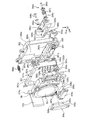
次に、図2を参照してCCD31を含む撮像ユニット30について説明する。図2は、撮像ユニット30の構成例を示す縦断側面図である。撮像ユニット30は、撮影光学系を透過し自己の光電変換面上に照射された光に対応した画像信号を得る撮像素子としてのCCD31と、CCD31の光電変換面側に配設され、撮影光学系を透過して照射される被写体光束から高周波成分を取り除く光学ローパスフィルタ(LPF)32と、この光学LPF32の前面側において所定間隔をあけて対向配置された防塵フィルタ33と、この防塵フィルタ33の周縁部に配設されて防塵フィルタ33に対して所定の振動を与えるための圧電素子34とを備える。
Next, the
ここで、CCD31のCCDチップ31aは固定板35上に配設されたフレキシブル基板31b上に直接実装され、フレキシブル基板31bの両端から出た接続部31c,31dが主回路基板36に設けられたコネクタ36a,36bを介して主回路基板36側と接続されている。また、CCD31が有する保護ガラス31eは、スペーサ31fを介してフレキシブル基板31b上に固着されている。
Here, the
また、CCD31と光学LPF32との間には、弾性部材等からなるフィルタ受け部材37が配設されている。このフィルタ受け部材37は、CCD31の前面側周縁部で光電変換面の有効範囲を避ける位置に配設され、かつ、光学LPF32の背面側周縁部の近傍に当接することで、CCD31と光学LPF32との間を略気密性が保持されるように構成されている。そして、CCD31と光学LPF32とを気密的に覆うホルダ38が配設されている。ホルダ38は、撮影光軸周りの略中央部分に矩形状の開口38aを有し、この開口38aの防塵フィルタ33側の内周縁部には断面が略L字形状の段部38bが形成され、開口38aに対してその後方側から光学LPF32およびCCD31が配設されている。ここで、光学LPF32の前面側周縁部を段部38bに対して略気密的に接触させるように配置することで、光学LPF32は段部38bによって撮影光軸方向における位置規制がなされ、ホルダ38の内部から前面側に対する抜け止めがなされる。
A
一方、ホルダ38の前面側の周縁部には、防塵フィルタ33を光学LPF32の前面に所定間隔あけて保持するために段部38b周りで段部38bよりも前面側に突出させた防塵フィルタ受け部38cが全周に亘って形成されている。全体として円形ないしは多角形の板状に形成された防塵フィルタ33は、板ばね等の弾性体によって形成されてねじ39で防塵フィルタ受け部38cに固定された押圧部材40による押圧状態で防塵フィルタ受け部38cに支持される。ここで、防塵フィルタ33の背面側の外周縁部に配設された圧電素子34部分には、防塵フィルタ受け部38cとの間に環状のシール41が介在され、気密状態が確保されている。撮像ユニット30は、このようにしてCCD31を搭載する所望の大きさに形成されたホルダ38を備える気密構造に構成されている。
On the other hand, a dust-proof filter receiving portion that protrudes to the front side of the
次に、本実施の形態のカメラの手ブレ補正機能について説明する。本実施の形態では、撮影光軸の方向をZ軸方向とした場合、撮影光軸に直交するXY平面内で直交する第1の方向であるX軸方向および第2の方向であるY軸方向に撮像素子であるCCD31をブレを補償するように変位移動させるものであり、手ブレ補正用の駆動装置を含む防振ユニットは、所定の周波電圧が印加されることにより駆動部に楕円振動を生ずる振動子を駆動源として用い、撮像ユニット30中のCCD31を搭載したホルダ38を移動対象物として構成される。
Next, the camera shake correction function of the camera according to the present embodiment will be described. In the present embodiment, when the direction of the photographing optical axis is the Z-axis direction, the X-axis direction that is the first direction orthogonal to the XY plane orthogonal to the photographing optical axis and the Y-axis direction that is the second direction. The image pickup device CCD 31 is displaced and moved so as to compensate for the shake, and the image stabilization unit including the shake correction drive device applies an elliptical vibration to the drive unit when a predetermined frequency voltage is applied. The generated vibrator is used as a drive source, and the
まず、本実施の形態の駆動装置で駆動源として用いる振動子の動作原理について説明する。図3は、振動子の動作原理を示す模式図である。振動子200は、所定の大きさで矩形状に形成された圧電体201と、この圧電体201の片面側に片寄らせて分極により中心対称に形成された一対の駆動電極202,203と、駆動電極202,203に対応する圧電体201の表面位置に設けられた駆動部としての駆動子204,205とを備える。駆動電極202に+の電圧を印加すると、図3(a)に示すように、分極構造の駆動電極202部分が伸びるように変形する一方、その背面側の圧電体201部分は伸びるように変形しないので全体として円弧状に変形する。逆に、駆動電極202に−の電圧を印加すると、図3(c)に示すように、分極構造の駆動電極202部分が縮むように変形する一方、その背面側の圧電体201部分は縮まないので全体として、図3(a)とは逆向きの円弧状に変形する。駆動電極203側でも同様である。
First, an operation principle of a vibrator used as a drive source in the drive device of the present embodiment will be described. FIG. 3 is a schematic diagram showing the operation principle of the vibrator. The
そこで、駆動子204,205の表面に楕円振動を発生させるには、圧電体201の分極された一方の駆動電極202に所定周波数の正弦波による周波電圧を印加するととともに、他方の駆動電極203に駆動電極202に印加する周波電圧の周波数と同じ周波数で位相のずれた正弦波による周波電圧を印加する。印加する周波電圧の周波数は、圧電体201の中央が屈曲振動の節となり、駆動子204,205部分が屈曲振動の腹となり、かつ、圧電体201の縦振動の節が屈曲振動の節と一致するような所定の数値に設定する。すると、印加する周波電圧の+,−の変化に伴い、振動子200は、図3(b)に示す復元状態を含めて、図3(a)〜(c)に示す屈曲振動を繰り返し、駆動子204,205の表面には楕円振動が発生する。よって、振動子200の駆動子204,205側に駆動対象となる移動体を押圧接触させて配設することで、移動体は駆動子204,205の表面に生ずる楕円振動の向きに従い移動することとなる。
Therefore, in order to generate elliptical vibrations on the surfaces of the
この際、駆動電極202,203に印加する周波電圧の位相差を変えることで、駆動子204,205の表面に発生する楕円振動の形状を変えることが可能であり、これにより振動子200に駆動されて移動する移動体の移動速度を変えることができる。例えば、周波電圧の位相差が0°であれば速度は0であるが、位相差を増やすと速度は次第に上がり、位相差90°で最大速度となり、また、90°を超えて位相差を大きくすると逆に速度は次第に下がり、位相差180°では再び速度0となる。位相差を負の値にすると、駆動子204,205に発生する楕円振動の回転方向が逆転し、移動体を逆方向に駆動することが可能となる。この場合も、位相差−90°のときに最大速度となる。
At this time, by changing the phase difference of the frequency voltage applied to the
つづいて、このような振動子を駆動源として用いる本実施の形態の防振ユニットについて図4〜図7を参照して説明する。図4は、本実施の形態の防振ユニットの構成例を示す分解斜視図であり、図5は、図4に示す各部の形状を簡略化して示す防振ユニットの概略側面図であり、図6は、図5中のX軸駆動機構部を抽出し拡大して示す概略側面図であり、図7は、そのガイド軸受構造を示す断面図である。 Next, the vibration isolating unit according to the present embodiment using such a vibrator as a drive source will be described with reference to FIGS. FIG. 4 is an exploded perspective view showing a configuration example of the image stabilization unit of the present embodiment, and FIG. 5 is a schematic side view of the image stabilization unit showing a simplified shape of each part shown in FIG. 6 is a schematic side view showing the X-axis drive mechanism in FIG. 5 extracted and enlarged, and FIG. 7 is a cross-sectional view showing the guide bearing structure.
まず、本実施の形態の防振ユニット300は、光学LPF32、防塵フィルタ33等ともにCCD31を搭載したホルダ38をX軸方向およびY軸方向に移動させる最終的な移動対象物とするものであり、撮影光軸周りの開口301aを囲む枠部301bを有する枠形状でホルダ38をY軸方向に移動可能に搭載するよう所望の大きさに形成されたX枠(第1の移動体部)301と、撮影光軸周りの開口302aを囲む枠部302bを有する枠形状でX枠301をX軸方向に移動可能に搭載するよう所望の大きさに形成されて図示しないカメラ本体に固着されたフレーム(固定部材)302と、を備える。
First, the
そして、X枠301をフレーム302に対してX軸方向に変位移動させるX軸駆動機構部310xと、ホルダ38をX枠301に対してY軸方向に変位移動させるY軸駆動機構310yとを備え、ホルダ38をX枠301とともにフレーム302に対してX軸方向に変位移動させるとともにX枠301に対してY軸方向に変位移動させることにより、ホルダ38に搭載されたCCD31はXY平面内でX軸方向およびY軸方向にブレを補償するように変位移動される。
An
ここで、X軸駆動機構部310xの構成について説明する。X軸駆動機構部310xは、X軸振動子(第1の振動子)320xと、X枠301に一体に固定されてX枠301とともに駆動対象となる移動体(第1の移動体)311xを構成する摺動体(第2の移動体部)330xと、X軸振動子320xを摺動体330x側に付勢する押圧機構(付勢手段)340xとを備える。
Here, the configuration of the
X軸振動子320xは、図3で説明した振動子200の動作原理に従い、所定の周波電圧が印加されることにより楕円振動が発生する駆動子(駆動部)321x,322xを矩形状の圧電体323xの片面に備える。X軸振動子320xは、圧電体323xの駆動子321x,322xと相反する側の中央位置に振動子ホルダ324xを有し、振動子ホルダ324xに形成された突起325xがフレーム302の溝342x(保持部)に嵌合することで、X軸振動子320xはX軸方向の移動が規制されるように位置決めされて保持されている。このような構成により駆動子321x,322xに生じる楕円振動による駆動力がX軸方向に作用する。
The
また、摺動体330xは、軸受け(被ガイド部)331x上に摺動板(摺動部)332xを固着してなる。軸受け331xは、X軸振動子320xの駆動子321x,322xが押圧されて摺動板332xに接触する位置でX枠301の一部に対して例えばビス333xにより一体となるように固定されている。なお、X枠301に対する摺動体330xの固定は、ビス止めに限らず、接着等であってもよく、固定方式は、特に問わない。ここで、摺動体330xは、図4からも明らかなように、所望の大きさに形成されたX枠301に比して小さな大きさ(X軸振動子320x相当の大きさ)で形成されたものである。また、X枠301が樹脂材料やアルミニウム合金、または振動吸収性の高いマグネシウム合金等を用いて形成されているのに対して、摺動板332xは耐磨耗性を有するセラミックス等を用いてX枠301よりも剛性が高くなるように形成され、軸受け331xは、フェライト系のステンレス等の焼入れ可能な材質に焼入れをして剛性を高めたものである。
The sliding
また、フレーム302は、フレーム302に形成された開口形状の取付部に配置されて摺動体330xの軸受け331xに対向するようにビス303xで固定された軸受け(ガイド部)304xを備える。この軸受け304xには、図7に示すように、X軸方向に沿わせたV溝305xが、磨耗防止用のV溝板306xを固着して形成されている。軸受け331xには、図7に示すように、軸受け304xのV溝305x(V溝板306x)に対向するV溝334xが形成されている。ここで、リテーナ335xで位置決めされた2個のボール336x(転動体)をV溝305x,334x間に挟み込ませることにより、軸受け304x,331xは、X軸方向に沿って1列に配列された2個のボール336xを有する構造とされている。2個のボール336xは、図6等に示すように、駆動子321x,322x直下となる位置付近に位置決めされており、リテーナ335xによりX軸方向の移動が規制されている。なお、転動体としてはボールに限らず、ローラでもよい。
In addition, the
押圧機構340xは、スペーサ343xを介して一端がビス344xによりフレーム302に固定されてX軸振動子320xを保持する押圧板341xと、この押圧板341xの他端側をフレーム302に固定するビス345x周りにスペーサ346xを介して配設されX軸振動子320xの駆動子321x,322xが摺動板332xに押圧接触するように押圧板341xを付勢する押圧ばね347xとを備える。押圧機構340xによる押圧力は、15N(ニュートン)程度の非常に大きな力に設定されている。
The
なお、軸受け331xはボール336xの中心を通り、V溝334xに平行な軸周りに回転可能であるが、軸受け331xがX枠301に一体化され、軸受け331xからX軸方向とは異なる方向の離れた位置(枠部302b上で最も離れた、ほぼ対角位置)でフレーム302とX枠301との間に1つのボール307x(転動体)が配設されている。このボール307xは、ボール307x近傍でフレーム302とX枠301との間に係止させたばね308xによる付勢力で挟持状態に維持され、フレーム302に対するX枠301の撮影光軸(Z軸)方向の間隔を維持するように位置決めする。ここで、ばね308xの付勢力は、ボール307xの挟持状態を維持できればよく、押圧ばね347xの付勢力に比して数段弱く設定されている。これにより、X枠301と摺動体330xとからなる移動体311xは、フレーム302に対して2個のボール336xと1個のボール307xとによる3点支持で移動し得る構成とされている。また、ボール307xをボール336xに対して、撮影光軸及び開口301aを挟んで反対側に配することで、ボール307xとボール336xとの距離を離間することができるので、安定した3点支持構造とすることができる。このように本実施の形態によれば、3つのボール(転動体)で、移動体311xの移動方向のガイドを行うとともに傾きをも規定することができ、安定した駆動が可能となる。
The
一方、Y軸駆動機構部310yも、基本構造はX軸駆動機構部310xと同様であり、同一または対応する部分には同一符号に添え字yを付して示し、説明も省略する。なお、Y軸駆動機構部310yは、フレーム302に代えてX枠301を固定部材とし、X枠301に代えてホルダ38を移動対象となる第1の移動体部(または第3の移動体部)とするものであり、ホルダ38には一体に固定されてホルダ38とともに駆動対象となる移動体(第2の移動体)311yを構成する摺動体(第2の移動体部または第4の移動体部)330yを備える。
On the other hand, the basic structure of the Y-axis
また、本実施の形態の防振ユニット300は、ボディユニット100のX軸周りのブレ(ピッチ方向のブレ)を検出するX軸ジャイロ350xとボディユニット100のY軸周りのブレ(ヨー方向のブレ)を検出するY軸ジャイロ350yとがフレーム302に配設されている。また、フレーム302に配設させたホール素子351とホール素子351に対向するようにホルダ38の一部に配設させたマグネット352とからなる位置検出センサ353を備える。そして、これらX軸ジャイロ350x、Y軸ジャイロ350yおよび位置検出センサ353からの信号に基づきX軸振動子320x、Y軸振動子320yに対する振動子駆動回路354を制御する防振制御回路355を備える。防振制御回路355は、Bucom50からの指示に従い制御動作を実行する。
In addition, the
次に、X軸駆動機構310xの動作について説明する。X軸振動子320xに所定の周波電圧を印加して駆動子321x,322xに楕円振動を発生させると、X軸振動子320xの駆動子321x,322xが押圧機構340による強い付勢力で摺動板332xに押圧接触しているので、摺動体330xは駆動子321x,322xの楕円振動の回転方向に駆動される。
Next, the operation of the
この際、X軸振動子320xに加える押圧力は強いため、仮に、摺動体330xを構成する摺動板332xや軸受け331xの剛性が弱いと、図8中に仮想線で示すように、付与する押圧力により摺動板332xや軸受け331xが撓んでしまい、駆動子321x,322xと摺動板332xとが片当りして動作が不安定になったり、動作しなくなってしまう。
At this time, since the pressing force applied to the
この点、本実施の形態では、摺動体330xを構成する摺動板332xおよび軸受け331xの剛性が高いため、駆動子321x,322xと摺動板332xとの押圧接触状態が安定し、楕円振動に伴う駆動力が摺動板332xに確実に伝達され、高効率で楕円振動の回転方向に駆動することができる。この際、摺動板332xを有する摺動体330x側はフレーム302に対して面接触ではなく、軸受け331x,304x部分でのボール336xによる転動方式で接触しているので、押圧力が強くても摺動体330xはフレーム302に対して摩擦の少ない状態で確実に移動することとなる。そして、軸受け331x,304xは、X軸方向に沿った1列のボールベアリング軸受構造からなるので、摺動体330xはX軸振動子320xによる駆動を受けた場合にX軸方向にのみ移動する。このように摺動体330xが移動すると、摺動体330xが固定されたX枠301も、摺動体330xと一体となってX軸方向に移動する。すなわち、X枠330xの移動方向も、X軸方向に沿った1列のボールベアリング軸受構造からなる軸受け331x,304x同士の係合によりガイドされる。
In this respect, in the present embodiment, since the sliding
このような動作において、軸受け331xはボール336xの中心を通り、V溝334xに平行な軸周りに回転可能であるが、軸受け331xがX枠301に一体化され、軸受け331xからX軸方向とは異なる方向の離れた位置でフレーム302とX枠301との間に1つのボール307xが配設され、X枠301と摺動体330xとからなる移動体311xが、フレーム302に対して2個のボール336xと1個のボール307xとによる離れた位置での3点支持とされているので、V溝334xに平行な軸周りの回転による煽りを生ずることなく安定してフレーム302上をX軸方向に移動する。よって、X軸振動子320xに対する強い押圧部分のガイド支持機構が、軸受け331x,304xによるX軸方向に沿った1列のボールベアリング軸受構造で済み、小型化・構造単純化が可能となる。
In such an operation, the
Y軸駆動機構310yも、X軸駆動機構310xの場合と同様に動作する。
The Y-
次に、手ブレ補正動作について説明する。カメラ操作SW52中の図示しない手ブレ補正SWがオンされており、図示しないメインSWがオンされると、Bucom50から防振制御回路355に対して、振動子駆動回路354が初期動作を実行する信号が伝達され、振動子駆動回路354からX軸振動子320xおよびY軸振動子320yに所定の周波電圧が印加され、CCD31の中心が撮影光軸上にくるようにX枠301およびホルダ38がX軸方向およびY軸方向に駆動される。
Next, the camera shake correction operation will be described. When a camera shake correction SW (not shown) in the camera operation SW 52 is turned on and a main SW (not shown) is turned on, a signal that causes the vibrator drive circuit 354 to execute an initial operation from the
そして、X軸ジャイロ350x、Y軸ジャイロ350yによって検出されるボディユニット100のブレ信号を防振制御回路355に取り込む。ここで、X軸ジャイロ350x、Y軸ジャイロ350yでは、その一方の軸周りのブレを検出する角速度センサから出力された信号が、処理回路で信号増幅後、A/D変換されて防振制御回路355に入力される。
The shake signal of the body unit 100 detected by the
防振制御回路355では、X軸ジャイロ350x、Y軸ジャイロ350yの出力信号に基づきブレ補正量を演算し、演算されたブレ補正量に応じた信号を振動子駆動回路354に出力する。CCD31を搭載したホルダ38およびX枠301は、振動子駆動回路354によって生成される電気信号によって動作するY軸振動子320y、X軸振動子320xによって駆動される。CCD31(ホルダ38)の駆動位置は、位置検出センサ353によって検出され、防振制御回路355に送られフィードバック制御が行われる。
The image
すなわち、防振制御回路355では、入力されたX軸ジャイロ350x、Y軸ジャイロ350yからの信号(以下、「ブレ信号」または「ブレ角速度信号」ともいう)に基づいて基準値を演算する。基準値の演算は、カメラの主電源を投入してから静止画撮影のための露光を行うまでの間、行う。この演算としては、比較的長時間のブレ信号の移動平均値を算出する方法、またはカットオフ周波数が比較的低いローパスフィルタによりDC成分を求める方法等があり、何れかの方法を用いればよい。この演算により求めた基準値をブレ信号より差分することにより、ブレ信号の低周波成分が除去された信号が得られる。そして、この信号と位置検出センサ353の出力信号とに基づいて振動子駆動回路354が制御されて、CCD31(ホルダ38)の位置をブレを補償するように移動させる。
That is, the image
ここで、静止画撮影時の補正動作について図9を参照して説明する。図9は、静止画撮影時の補正動作を示す概略フローチャートである。なお、本動作は、レリーズSWにより撮影準備開始が指示される前(IR ON前)においては行われず、レリーズSWにより撮影準備開始が指示されると(1R ONになると)、開始する。 Here, the correction operation during still image shooting will be described with reference to FIG. FIG. 9 is a schematic flowchart showing a correction operation during still image shooting. Note that this operation is not performed before the start of shooting preparation is instructed by the release SW (before IR ON), and starts when the start of shooting preparation is instructed by the release SW (when 1R is turned ON).
本動作が開始されると、上述の基準値を用いて補正量を演算し、算出された補正量に従ってブレ補正駆動を開始する(ステップS11)。続いて、レリーズSWによる撮影準備開始指示が解除されたか(1R OFFになったか)否かを判定し(ステップS12)、解除された場合には(ステップS12;Yes)、ステップS11で開始されたブレ補正駆動を停止するとともにCCD31をセンタリングし(ステップS17)、撮影準備開始の指示待ち状態(1R待ち状態)となる。 When this operation is started, a correction amount is calculated using the above-described reference value, and shake correction driving is started according to the calculated correction amount (step S11). Subsequently, it is determined whether or not the shooting preparation start instruction by the release SW has been canceled (1R has been turned OFF) (step S12). If the instruction has been canceled (step S12; Yes), the process is started in step S11. The blur correction drive is stopped and the CCD 31 is centered (step S17), and the camera waits for an instruction to start photographing preparation (1R wait state).
一方、レリーズSWによる撮影準備開始指示が解除されない場合には(ステップS12;No)、続いて、レリーズSWにより撮影開始が指示されたか(2R ONになったか)否かを判定し(ステップS13)、指示されない場合には(ステップS13;No)、ステップS12に戻り、指示待ち状態で待機する。レリーズSWにより撮影開始が指示された場合には(ステップS13;Yes)、ステップS11で開始されたブレ補正駆動を停止するとともにCCD31をセンタリングする(ステップS14)。続いて、保持された基準値を用いて補正量を演算し、その補正量に従ってブレ補正駆動を開始する(ステップS15)。そして、露光を行い(ステップS16)、露光が終了すると、ブレ補正駆動を停止するとともにCCD31をセンタリングし(ステップS17)、撮影準備開始の指示待ち状態(1R待ち状態)となる。 On the other hand, when the shooting preparation start instruction by the release SW is not canceled (step S12; No), it is subsequently determined whether or not the shooting start is instructed by the release SW (2R ON) (step S13). If not instructed (step S13; No), the process returns to step S12 and waits in an instruction waiting state. When the start of shooting is instructed by the release SW (step S13; Yes), the blur correction driving started in step S11 is stopped and the CCD 31 is centered (step S14). Subsequently, a correction amount is calculated using the held reference value, and blur correction driving is started according to the correction amount (step S15). Then, exposure is performed (step S16), and when the exposure is completed, the blur correction driving is stopped and the CCD 31 is centered (step S17), and the camera waits for an instruction to start photographing preparation (1R waiting state).
本実施の形態によれば、効率が高く大きな駆動力を得やすい楕円振動を生ずる振動子320x,320yを駆動源として用いる一方、移動体311x,311y側は、本来の移動対象物として所望の大きさに形成されたX枠301やホルダ38のような第1の移動体部とこの第1の移動体部よりも小さな摺動体330xや摺動体330yのような第2の移動体部との分割構造で両者を固定して一体化し、小さい方の第2の移動体部に摺動板332x,332yと軸受け331x,331yとを設けることで振動子320x,320yからの駆動力伝達機能と移動方向ガイド機能とを集約させ、大きい方の第1の移動体部は第2の移動体部と一体となって単に追従移動するように構成し、小さい方の第2の移動体部側のみを剛性が高くなるように形成することで駆動力伝達の高効率化を図ることができる一方、第1の移動体部側は第2の移動体部側ほどの高い剛性を必要とせず軽量な材質により所望の大きさに形成すればよく、かつ、第1の移動体部の移動方向を規制する専用のガイド機構を要せず、全体として駆動力が大きくて高効率で小型・軽量化を図ることができる。
According to the present embodiment,
31 CCD
38 ホルダ
50 Bucom
301 X枠
302 フレーム
304x,304y 軸受け
307x,307y ボール
320x X軸振動子
320y Y軸振動子
321x,322x 駆動子
321y,322y 駆動子
330x,330y 摺動体
331x,331y 軸受け
332x,332y 摺動板
336x,336y ボール
340x,340y 押圧機構
342x,342y 保持部
31 CCD
38
301
Claims (8)
前記振動子を保持する保持部を有する固定部材と、
前記振動子の楕円振動により駆動されて前記固定部材に対して移動する移動体と、
を備え、
前記移動体は、
所望の大きさに形成された第1の移動体部と、
前記駆動部が押圧されて接触する摺動部と、該摺動部と相反する側に設けられて前記固定部材が有するガイド部に係合して移動方向がガイドされる被ガイド部とを有し、前記第1の移動体部より剛性が高く、かつ、前記第1の移動体部より小さく形成されて該第1の移動体部に固定された第2の移動体部とからなることを特徴とする駆動装置。 A vibrator that generates elliptical vibration in the drive unit when a predetermined frequency voltage is applied;
A fixing member having a holding portion for holding the vibrator;
A moving body that is driven by the elliptical vibration of the vibrator and moves relative to the fixed member;
With
The moving body is
A first moving body portion formed in a desired size;
A sliding portion that is in contact with the driving portion when pressed, and a guided portion that is provided on a side opposite to the sliding portion and engages with a guide portion included in the fixing member to guide a moving direction. And a second moving body portion that is higher in rigidity than the first moving body portion and is smaller than the first moving body portion and is fixed to the first moving body portion. The drive device characterized.
前記ガイド部から移動方向とは異なる方向の離れた位置で前記第1の移動体部と前記固定部材との間に付勢力による挟持状態で配設された位置決め用の1つの転動体を備えることを特徴とする請求項1〜4のいずれか一つに記載の駆動装置。 The guide part and the guided part have rolling elements arranged in a line along the movement direction,
A single rolling element for positioning disposed in a clamped state by a biasing force between the first moving body portion and the fixed member at a position away from the guide portion in a direction different from the moving direction; The drive device according to claim 1, wherein
前記第1の振動子を保持する第1の保持部を有する固定部材と、
前記第1の振動子の前記駆動部が押圧され、かつ、前記固定部材が有するガイド部により第1の方向に移動方向が規制され、前記第1の振動子の楕円振動により駆動されて前記固定部材に対して第1の方向に移動する第1の移動体と、
第2の保持部を有する前記第1の移動体に保持されて、所定の周波電圧が印加されることにより駆動部に楕円振動を生ずる第2の振動子と、
前記第2の振動子の前記駆動部が押圧され、かつ、前記第1の移動体が有するガイド部により第1の方向と異なる第2の方向に移動方向が規制され、前記第2の振動子の楕円振動により駆動されて前記第1の移動体に対して第2の方向に移動する第2の移動体と、
を備え、
前記第1,第2の移動体のうち、少なくとも一方の移動体は、
所望の大きさに形成された第1の移動体部と、
前記駆動部が接触する摺動部と、該摺動部と相反する側に設けられて前記ガイド部に係合して移動方向がガイドされる被ガイド部とを有し、前記第1の移動体部より剛性が高く、かつ、前記第1の移動体部より小さく形成されて該第1の移動体部に固定された第2の移動体部とからなることを特徴とする駆動装置。 A first vibrator that generates elliptical vibration in the drive unit when a predetermined frequency voltage is applied;
A fixing member having a first holding portion for holding the first vibrator;
The driving portion of the first vibrator is pressed, the moving direction is regulated in a first direction by a guide portion included in the fixing member, and the fixing is driven by elliptic vibration of the first vibrator. A first moving body that moves in a first direction relative to the member;
A second vibrator that is held by the first moving body having a second holding unit and generates elliptical vibration in the driving unit when a predetermined frequency voltage is applied;
The driving portion of the second vibrator is pressed, and the moving direction is regulated in a second direction different from the first direction by the guide portion of the first moving body, and the second vibrator A second moving body that is driven by the elliptical vibration of the first moving body and moves in a second direction with respect to the first moving body;
With
Of the first and second moving bodies, at least one moving body is:
A first moving body portion formed in a desired size;
A sliding portion that is in contact with the driving portion; and a guided portion that is provided on a side opposite to the sliding portion and that engages with the guide portion to guide a movement direction. A drive device comprising: a second moving body portion having a rigidity higher than that of the body portion and being smaller than the first moving body portion and fixed to the first moving body portion.
前記マイクロコンピュータの指示に基づき所定の周波電圧が印加されることにより駆動部に楕円振動を生ずる第1の振動子と、
前記第1の振動子を保持する第1の保持部を有して、撮像装置本体に固着された固定部材と、
前記第1の振動子の前記駆動部が押圧され、かつ、前記固定部材が有するガイド部により第1の方向に移動方向が規制され、前記第1の振動子の楕円振動により駆動されて前記固定部材に対して第1の方向に移動する第1の移動体と、
第2の保持部を有する前記第1の移動体に保持されて、前記マイクロコンピュータの指示に基づき所定の周波電圧が印加されることにより駆動部に楕円振動を生ずる第2の振動子と、
前記第2の振動子の前記駆動部が押圧され、かつ、前記第1の移動体が有するガイド部により第2の方向に移動方向が規制され、前記第2の振動子の楕円振動により駆動されて前記第1の移動体に対して第2の方向に移動する、前記撮像素子を撮影光軸上に保持した第2の移動体と、
を備え、
前記第1,第2の移動体のうち、少なくとも一方の移動体は、
所望の大きさに形成された第1の移動体部と、
前記駆動部が接触する摺動部と、該摺動部と相反する側に設けられて前記ガイド部に係合して移動方向がガイドされる被ガイド部とを有し、前記第1の移動体部より剛性が高く、かつ、前記第1の移動体部より小さく形成されて該第1の移動体部に固定された第2の移動体部とからなることを特徴とする撮像装置。 In an imaging apparatus including a microcomputer that controls the operation of the entire imaging apparatus and moving the imaging element in a first direction and a second direction orthogonal to each other in a plane orthogonal to the imaging optical axis so as to compensate for blurring ,
A first vibrator that generates elliptical vibration in the drive unit when a predetermined frequency voltage is applied based on an instruction from the microcomputer;
A fixing member having a first holding part for holding the first vibrator and fixed to the imaging apparatus main body;
The driving portion of the first vibrator is pressed, the moving direction is regulated in a first direction by a guide portion included in the fixing member, and the fixing is driven by elliptic vibration of the first vibrator. A first moving body that moves in a first direction relative to the member;
A second vibrator that is held by the first moving body having a second holding unit and generates elliptical vibration in the driving unit when a predetermined frequency voltage is applied based on an instruction of the microcomputer;
The driving portion of the second vibrator is pressed, the moving direction is regulated in the second direction by the guide portion of the first moving body, and the second vibrator is driven by the elliptical vibration of the second vibrator. A second moving body that moves in the second direction with respect to the first moving body and that holds the image sensor on the photographing optical axis;
With
Of the first and second moving bodies, at least one moving body is:
A first moving body portion formed in a desired size;
A sliding portion that is in contact with the driving portion; and a guided portion that is provided on a side opposite to the sliding portion and that engages with the guide portion to guide a movement direction. An imaging apparatus comprising: a second moving body portion having a rigidity higher than that of the body portion and being smaller than the first moving body portion and fixed to the first moving body portion.
前記マイクロコンピュータの指示に基づき所定の周波電圧が印加されることにより駆動部に楕円振動を生ずる第1の振動子と、
撮影光軸周りの開口を囲む枠形状に形成されるとともに前記第1の振動子を保持する第1の保持部を有して、撮像装置本体に固着された固定部材と、
撮影光軸周りの開口を囲む枠形状で所望の大きさに形成された第1の移動体部と、
前記第1の振動子の前記駆動部が押圧されて接触する摺動部と、該摺動部と相反する側に設けられて前記固定部材が有するガイド部に係合して第1の方向に移動方向がガイドされる被ガイド部とを有し、前記第1の移動体部より剛性が高く、かつ、前記第1の移動体部より小さく形成されて該第1の移動体部に固定され、前記第1の振動子の楕円振動により駆動されて前記固定部材に対して第1の方向に移動する第2の移動体部と、
第2の保持部を有する前記第1の移動体部に保持されて、前記マイクロコンピュータの指示に基づき所定の周波電圧が印加されることにより駆動部に楕円振動を生ずる第2の振動子と、
撮影光軸上に前記撮像素子を保持して前記第1の移動体部の前記開口に配設される所望の大きさに形成された第3の移動体部と、
前記第2の振動子の前記駆動部が押圧されて接触する摺動部と、該摺動部と相反する側に設けられて前記第1の移動体部が有するガイド部に係合して第2の方向に移動方向がガイドされる被ガイド部とを有し、前記第3の移動体部より剛性が高く、かつ、前記第3の移動体部より小さく形成されて該第3の移動体部に固定され、前記第2の振動子の楕円振動により駆動されて前記第1の移動体部に対して第2の方向に移動する第4の移動体部と、
を備えることを特徴とする撮像装置。 In an imaging apparatus including a microcomputer that controls the operation of the entire imaging apparatus and moving the imaging element in a first direction and a second direction orthogonal to each other in a plane orthogonal to the imaging optical axis so as to compensate for blurring ,
A first vibrator that generates elliptical vibration in the drive unit when a predetermined frequency voltage is applied based on an instruction from the microcomputer;
A fixing member that is formed in a frame shape surrounding an opening around the photographing optical axis and has a first holding part that holds the first vibrator, and is fixed to the imaging apparatus body;
A first moving body portion having a frame shape surrounding an opening around the photographing optical axis and having a desired size;
The sliding portion of the first vibrator that is pressed and brought into contact with the sliding portion and the guide portion provided on the side opposite to the sliding portion and engaged with the fixing member in the first direction A guided portion whose movement direction is guided, which is higher in rigidity than the first moving body portion and smaller than the first moving body portion, and is fixed to the first moving body portion. A second moving body that is driven by elliptical vibration of the first vibrator and moves in a first direction with respect to the fixed member;
A second vibrator that is held by the first moving body portion having a second holding portion and generates elliptical vibration in the driving portion when a predetermined frequency voltage is applied based on an instruction of the microcomputer;
A third moving body portion that is formed in a desired size and that is disposed in the opening of the first moving body portion while holding the imaging element on a photographing optical axis;
The sliding portion of the second vibrator that is pressed and brought into contact with the sliding portion is engaged with a guide portion that is provided on the side opposite to the sliding portion and that the first moving body portion has. And a guided portion whose movement direction is guided in the direction of 2, the third moving body portion being higher in rigidity than the third moving body portion and smaller than the third moving body portion. A fourth moving body portion fixed to the portion and driven by the elliptical vibration of the second vibrator to move in the second direction with respect to the first moving body portion;
An imaging apparatus comprising:
Priority Applications (3)
| Application Number | Priority Date | Filing Date | Title |
|---|---|---|---|
| JP2007291313A JP5230994B2 (en) | 2006-12-15 | 2007-11-08 | Driving device and imaging device |
| US11/999,643 US7893598B2 (en) | 2006-12-15 | 2007-12-05 | Driving apparatus and image pickup apparatus |
| CN2007101957689A CN101207343B (en) | 2006-12-15 | 2007-12-14 | Driving apparatus and image pickup apparatus |
Applications Claiming Priority (3)
| Application Number | Priority Date | Filing Date | Title |
|---|---|---|---|
| JP2006338715 | 2006-12-15 | ||
| JP2006338715 | 2006-12-15 | ||
| JP2007291313A JP5230994B2 (en) | 2006-12-15 | 2007-11-08 | Driving device and imaging device |
Publications (3)
| Publication Number | Publication Date |
|---|---|
| JP2008172995A true JP2008172995A (en) | 2008-07-24 |
| JP2008172995A5 JP2008172995A5 (en) | 2010-12-24 |
| JP5230994B2 JP5230994B2 (en) | 2013-07-10 |
Family
ID=39567291
Family Applications (1)
| Application Number | Title | Priority Date | Filing Date |
|---|---|---|---|
| JP2007291313A Active JP5230994B2 (en) | 2006-12-15 | 2007-11-08 | Driving device and imaging device |
Country Status (2)
| Country | Link |
|---|---|
| JP (1) | JP5230994B2 (en) |
| CN (1) | CN101207343B (en) |
Cited By (8)
| Publication number | Priority date | Publication date | Assignee | Title |
|---|---|---|---|---|
| EP2202570A1 (en) | 2008-12-24 | 2010-06-30 | Olympus Imaging Corporation | Driving apparatus and image pickup apparatus using the same |
| JP2012055152A (en) * | 2010-08-04 | 2012-03-15 | Panasonic Corp | Drive unit |
| US8436513B2 (en) | 2010-04-06 | 2013-05-07 | Panasonic Corporation | Drive unit |
| JP2014014256A (en) * | 2012-06-05 | 2014-01-23 | Canon Inc | An oscillatory wave drive unit, a two-dimensional drive unit, an image blur correction device, an interchangeable lens, an imaging apparatus, and an automatic stage |
| KR20190062206A (en) * | 2017-11-27 | 2019-06-05 | 캐논 가부시끼가이샤 | Vibration type motor, lens apparatus, and electronic apparatus |
| CN110138267A (en) * | 2018-02-08 | 2019-08-16 | 佳能株式会社 | Vibration wave motor and lens driving device including vibration wave motor |
| JP2019140864A (en) * | 2018-02-15 | 2019-08-22 | キヤノン株式会社 | Drive device with vibration wave motor |
| JP2019154145A (en) * | 2018-03-02 | 2019-09-12 | キヤノン株式会社 | Vibration wave motor and lens device |
Families Citing this family (6)
| Publication number | Priority date | Publication date | Assignee | Title |
|---|---|---|---|---|
| US7941045B2 (en) * | 2008-10-30 | 2011-05-10 | Panasonic Corporation | Camera body, interchangeable lens unit, and imaging apparatus |
| JP6053535B2 (en) * | 2013-01-25 | 2016-12-27 | キヤノン株式会社 | Correction optical device, image shake correction device, and imaging device |
| JP6188366B2 (en) * | 2013-03-21 | 2017-08-30 | キヤノン株式会社 | Actuator and optical equipment |
| KR102631961B1 (en) * | 2015-11-02 | 2024-01-31 | 엘지이노텍 주식회사 | A lens moving unit and a camera module including the same |
| TWI650587B (en) * | 2016-08-04 | 2019-02-11 | 台灣東電化股份有限公司 | Lens drive |
| CN108072957B (en) * | 2016-11-14 | 2022-05-24 | 台湾东电化股份有限公司 | Optical drive mechanism |
Citations (3)
| Publication number | Priority date | Publication date | Assignee | Title |
|---|---|---|---|---|
| JP2001141977A (en) * | 1999-11-15 | 2001-05-25 | Sony Corp | Lens driving device and electronic apparatus having it |
| JP2003110919A (en) * | 2001-10-01 | 2003-04-11 | Minolta Co Ltd | Image pickup device |
| JP2006330077A (en) * | 2005-05-23 | 2006-12-07 | Canon Inc | Optical equipment |
Family Cites Families (1)
| Publication number | Priority date | Publication date | Assignee | Title |
|---|---|---|---|---|
| CN1011090B (en) * | 1985-04-01 | 1991-01-02 | 株式会社岛津制作所 | X-ray profiles photographic device with multi-track |
-
2007
- 2007-11-08 JP JP2007291313A patent/JP5230994B2/en active Active
- 2007-12-14 CN CN2007101957689A patent/CN101207343B/en not_active Expired - Fee Related
Patent Citations (3)
| Publication number | Priority date | Publication date | Assignee | Title |
|---|---|---|---|---|
| JP2001141977A (en) * | 1999-11-15 | 2001-05-25 | Sony Corp | Lens driving device and electronic apparatus having it |
| JP2003110919A (en) * | 2001-10-01 | 2003-04-11 | Minolta Co Ltd | Image pickup device |
| JP2006330077A (en) * | 2005-05-23 | 2006-12-07 | Canon Inc | Optical equipment |
Cited By (19)
| Publication number | Priority date | Publication date | Assignee | Title |
|---|---|---|---|---|
| EP2202570A1 (en) | 2008-12-24 | 2010-06-30 | Olympus Imaging Corporation | Driving apparatus and image pickup apparatus using the same |
| JP2010151970A (en) * | 2008-12-24 | 2010-07-08 | Olympus Imaging Corp | Drive device and image capturing apparatus using the same |
| US8164639B2 (en) | 2008-12-24 | 2012-04-24 | Olympus Imaging Corp. | Driving apparatus and image pickup apparatus using the same |
| US8436513B2 (en) | 2010-04-06 | 2013-05-07 | Panasonic Corporation | Drive unit |
| JP2012055152A (en) * | 2010-08-04 | 2012-03-15 | Panasonic Corp | Drive unit |
| US8729773B2 (en) | 2010-08-04 | 2014-05-20 | Panasonic Corporation | Drive unit |
| JP2014014256A (en) * | 2012-06-05 | 2014-01-23 | Canon Inc | An oscillatory wave drive unit, a two-dimensional drive unit, an image blur correction device, an interchangeable lens, an imaging apparatus, and an automatic stage |
| US9647576B2 (en) | 2012-06-05 | 2017-05-09 | Canon Kabushiki Kaisha | Vibration type driving apparatus, two-dimensional driving apparatus, image-blur correction apparatus, interchangeable lens, image-pickup apparatus, and automatic stage |
| KR20190062206A (en) * | 2017-11-27 | 2019-06-05 | 캐논 가부시끼가이샤 | Vibration type motor, lens apparatus, and electronic apparatus |
| KR102372496B1 (en) | 2017-11-27 | 2022-03-10 | 캐논 가부시끼가이샤 | Vibration type motor, lens apparatus, and electronic apparatus |
| US11418134B2 (en) | 2017-11-27 | 2022-08-16 | Canon Kabushiki Kaisha | Vibration type motor for guiding movement of a friction member, and lens apparatus and electronic apparatus including said motor |
| CN110138267A (en) * | 2018-02-08 | 2019-08-16 | 佳能株式会社 | Vibration wave motor and lens driving device including vibration wave motor |
| JP2019140764A (en) * | 2018-02-08 | 2019-08-22 | キヤノン株式会社 | Vibration wave motor and lens driving device provided with the same |
| JP7007943B2 (en) | 2018-02-08 | 2022-01-25 | キヤノン株式会社 | Lens drive device with vibration wave motor and vibration wave motor |
| JP2019140864A (en) * | 2018-02-15 | 2019-08-22 | キヤノン株式会社 | Drive device with vibration wave motor |
| JP6995660B2 (en) | 2018-02-15 | 2022-01-14 | キヤノン株式会社 | Drive device with vibration wave motor |
| US11283370B2 (en) | 2018-02-15 | 2022-03-22 | Canon Kabushiki Kaisha | Vibration wave motor and driving device including the vibration wave motor |
| JP2019154145A (en) * | 2018-03-02 | 2019-09-12 | キヤノン株式会社 | Vibration wave motor and lens device |
| JP7034770B2 (en) | 2018-03-02 | 2022-03-14 | キヤノン株式会社 | Vibration wave motor and lens device |
Also Published As
| Publication number | Publication date |
|---|---|
| CN101207343B (en) | 2012-05-09 |
| CN101207343A (en) | 2008-06-25 |
| JP5230994B2 (en) | 2013-07-10 |
Similar Documents
| Publication | Publication Date | Title |
|---|---|---|
| JP5230994B2 (en) | Driving device and imaging device | |
| JP4981547B2 (en) | Driving device and imaging device | |
| JP4981484B2 (en) | Drive device | |
| JP5185684B2 (en) | Driving device and imaging device | |
| JP5284605B2 (en) | Drive device and shake correction device | |
| US7893598B2 (en) | Driving apparatus and image pickup apparatus | |
| JP2009011097A (en) | Drive unit | |
| JP5053985B2 (en) | DRIVE DEVICE AND IMAGING DEVICE USING THE DRIVE DEVICE | |
| JP2009008929A (en) | Shake correctable imaging device | |
| JP2008216570A (en) | Imaging apparatus | |
| JP2009008944A (en) | Shake correcting device | |
| JP5165289B2 (en) | Drive device | |
| JP2009008858A (en) | Shake correcting device and imaging device | |
| JP2008220030A (en) | Driving device and image pickup apparatus | |
| JP2009265416A (en) | Driving device and imaging apparatus | |
| JP2009165086A (en) | Imaging device | |
| JP2010048977A (en) | Image sensor driving device | |
| JP5132410B2 (en) | Driving device and imaging device | |
| JP2006330077A (en) | Optical equipment | |
| JP2009294613A (en) | Imaging-element drive device | |
| JP6509070B2 (en) | Image blurring correction apparatus, lens barrel and imaging apparatus |
Legal Events
| Date | Code | Title | Description |
|---|---|---|---|
| A521 | Written amendment |
Free format text: JAPANESE INTERMEDIATE CODE: A523 Effective date: 20101108 |
|
| A621 | Written request for application examination |
Free format text: JAPANESE INTERMEDIATE CODE: A621 Effective date: 20101108 |
|
| A977 | Report on retrieval |
Free format text: JAPANESE INTERMEDIATE CODE: A971007 Effective date: 20120613 |
|
| A131 | Notification of reasons for refusal |
Free format text: JAPANESE INTERMEDIATE CODE: A131 Effective date: 20120619 |
|
| A521 | Written amendment |
Free format text: JAPANESE INTERMEDIATE CODE: A523 Effective date: 20120725 |
|
| TRDD | Decision of grant or rejection written | ||
| A01 | Written decision to grant a patent or to grant a registration (utility model) |
Free format text: JAPANESE INTERMEDIATE CODE: A01 Effective date: 20130226 |
|
| A61 | First payment of annual fees (during grant procedure) |
Free format text: JAPANESE INTERMEDIATE CODE: A61 Effective date: 20130321 |
|
| FPAY | Renewal fee payment (event date is renewal date of database) |
Free format text: PAYMENT UNTIL: 20160329 Year of fee payment: 3 |
|
| S111 | Request for change of ownership or part of ownership |
Free format text: JAPANESE INTERMEDIATE CODE: R313111 |
|
| R350 | Written notification of registration of transfer |
Free format text: JAPANESE INTERMEDIATE CODE: R350 |
|
| S531 | Written request for registration of change of domicile |
Free format text: JAPANESE INTERMEDIATE CODE: R313531 |
|
| R350 | Written notification of registration of transfer |
Free format text: JAPANESE INTERMEDIATE CODE: R350 |
|
| R250 | Receipt of annual fees |
Free format text: JAPANESE INTERMEDIATE CODE: R250 |