JP2012055152A - Drive unit - Google Patents

Drive unit Download PDF

Info

Publication number
JP2012055152A
JP2012055152A JP2011136051A JP2011136051A JP2012055152A JP 2012055152 A JP2012055152 A JP 2012055152A JP 2011136051 A JP2011136051 A JP 2011136051A JP 2011136051 A JP2011136051 A JP 2011136051A JP 2012055152 A JP2012055152 A JP 2012055152A
Authority
JP
Japan
Prior art keywords
actuator
moving body
roller
moving
sliding plate
Prior art date
Legal status (The legal status is an assumption and is not a legal conclusion. Google has not performed a legal analysis and makes no representation as to the accuracy of the status listed.)
Granted
Application number
JP2011136051A
Other languages
Japanese (ja)
Other versions
JP5909624B2 (en
Inventor
Hidekazu Nagaoka
英一 長岡
Hideaki Koe
秀明 向江
Current Assignee (The listed assignees may be inaccurate. Google has not performed a legal analysis and makes no representation or warranty as to the accuracy of the list.)
Panasonic Corp
Original Assignee
Panasonic Corp
Priority date (The priority date is an assumption and is not a legal conclusion. Google has not performed a legal analysis and makes no representation as to the accuracy of the date listed.)
Filing date
Publication date
Application filed by Panasonic Corp filed Critical Panasonic Corp
Priority to JP2011136051A priority Critical patent/JP5909624B2/en
Publication of JP2012055152A publication Critical patent/JP2012055152A/en
Application granted granted Critical
Publication of JP5909624B2 publication Critical patent/JP5909624B2/en
Expired - Fee Related legal-status Critical Current
Anticipated expiration legal-status Critical

Links

Images

Classifications

    • FMECHANICAL ENGINEERING; LIGHTING; HEATING; WEAPONS; BLASTING
    • F16ENGINEERING ELEMENTS AND UNITS; GENERAL MEASURES FOR PRODUCING AND MAINTAINING EFFECTIVE FUNCTIONING OF MACHINES OR INSTALLATIONS; THERMAL INSULATION IN GENERAL
    • F16HGEARING
    • F16H19/00Gearings comprising essentially only toothed gears or friction members and not capable of conveying indefinitely-continuing rotary motion
    • F16H19/02Gearings comprising essentially only toothed gears or friction members and not capable of conveying indefinitely-continuing rotary motion for interconverting rotary or oscillating motion and reciprocating motion
    • F16H19/025Gearings comprising essentially only toothed gears or friction members and not capable of conveying indefinitely-continuing rotary motion for interconverting rotary or oscillating motion and reciprocating motion comprising a friction shaft
    • HELECTRICITY
    • H02GENERATION; CONVERSION OR DISTRIBUTION OF ELECTRIC POWER
    • H02NELECTRIC MACHINES NOT OTHERWISE PROVIDED FOR
    • H02N2/00Electric machines in general using piezoelectric effect, electrostriction or magnetostriction
    • H02N2/0005Electric machines in general using piezoelectric effect, electrostriction or magnetostriction producing non-specific motion; Details common to machines covered by H02N2/02 - H02N2/16
    • H02N2/001Driving devices, e.g. vibrators
    • H02N2/003Driving devices, e.g. vibrators using longitudinal or radial modes combined with bending modes
    • H02N2/004Rectangular vibrators
    • HELECTRICITY
    • H02GENERATION; CONVERSION OR DISTRIBUTION OF ELECTRIC POWER
    • H02NELECTRIC MACHINES NOT OTHERWISE PROVIDED FOR
    • H02N2/00Electric machines in general using piezoelectric effect, electrostriction or magnetostriction
    • H02N2/0005Electric machines in general using piezoelectric effect, electrostriction or magnetostriction producing non-specific motion; Details common to machines covered by H02N2/02 - H02N2/16
    • H02N2/005Mechanical details, e.g. housings
    • H02N2/0055Supports for driving or driven bodies; Means for pressing driving body against driven body
    • HELECTRICITY
    • H02GENERATION; CONVERSION OR DISTRIBUTION OF ELECTRIC POWER
    • H02NELECTRIC MACHINES NOT OTHERWISE PROVIDED FOR
    • H02N2/00Electric machines in general using piezoelectric effect, electrostriction or magnetostriction
    • H02N2/02Electric machines in general using piezoelectric effect, electrostriction or magnetostriction producing linear motion, e.g. actuators; Linear positioners ; Linear motors
    • H02N2/026Electric machines in general using piezoelectric effect, electrostriction or magnetostriction producing linear motion, e.g. actuators; Linear positioners ; Linear motors by pressing one or more vibrators against the driven body
    • HELECTRICITY
    • H10SEMICONDUCTOR DEVICES; ELECTRIC SOLID-STATE DEVICES NOT OTHERWISE PROVIDED FOR
    • H10NELECTRIC SOLID-STATE DEVICES NOT OTHERWISE PROVIDED FOR
    • H10N30/00Piezoelectric or electrostrictive devices
    • H10N30/20Piezoelectric or electrostrictive devices with electrical input and mechanical output, e.g. functioning as actuators or vibrators
    • H10N30/202Piezoelectric or electrostrictive devices with electrical input and mechanical output, e.g. functioning as actuators or vibrators using longitudinal or thickness displacement combined with bending, shear or torsion displacement
    • H10N30/2023Piezoelectric or electrostrictive devices with electrical input and mechanical output, e.g. functioning as actuators or vibrators using longitudinal or thickness displacement combined with bending, shear or torsion displacement having polygonal or rectangular shape
    • HELECTRICITY
    • H10SEMICONDUCTOR DEVICES; ELECTRIC SOLID-STATE DEVICES NOT OTHERWISE PROVIDED FOR
    • H10NELECTRIC SOLID-STATE DEVICES NOT OTHERWISE PROVIDED FOR
    • H10N30/00Piezoelectric or electrostrictive devices
    • H10N30/50Piezoelectric or electrostrictive devices having a stacked or multilayer structure
    • YGENERAL TAGGING OF NEW TECHNOLOGICAL DEVELOPMENTS; GENERAL TAGGING OF CROSS-SECTIONAL TECHNOLOGIES SPANNING OVER SEVERAL SECTIONS OF THE IPC; TECHNICAL SUBJECTS COVERED BY FORMER USPC CROSS-REFERENCE ART COLLECTIONS [XRACs] AND DIGESTS
    • Y10TECHNICAL SUBJECTS COVERED BY FORMER USPC
    • Y10TTECHNICAL SUBJECTS COVERED BY FORMER US CLASSIFICATION
    • Y10T74/00Machine element or mechanism
    • Y10T74/18Mechanical movements
    • Y10T74/18568Reciprocating or oscillating to or from alternating rotary

Abstract

PROBLEM TO BE SOLVED: To increase a movement stroke in which a movable body normally operates.SOLUTION: A drive unit 1 includes: an actuator body 4 outputting the driving force by vibrating; a movable body 11 with which the actuator body 4 contacts and moving in a predetermined movement direction relative to the actuator body 4; and a roller 6 placed in a position which faces the actuator body 4 across the moving body 11 and holding the moving body 11 with the actuator body 4. A portion of the movable body 11, which is in contact with the roller 6, has an elasticity coefficient smaller than that of the roller 6.

Description

ここに開示された技術は、移動体を振動型アクチュエータで駆動する駆動装置に関するものである。   The technology disclosed herein relates to a drive device that drives a moving body with a vibration actuator.

振動型アクチュエータを用いた駆動装置は従来より知られている。例えば、特許文献1に係る駆動装置は、圧電素子で構成された振動型アクチュエータを振動させることによって、移動体を駆動している。詳しくは、該駆動装置は、移動体を振動型アクチュエータと、該振動型アクチュエータに対向する対向部材とで挟み込んでいる。これら振動型アクチュエータと対向部材とは、互いに、移動体を押圧する方向に付勢されている。これにより、振動型アクチュエータと移動体との間の摩擦力を高めている。この状態で振動型アクチュエータを振動させると、その振動に伴って駆動子が変位し、移動体が駆動される。   A drive device using a vibration type actuator has been conventionally known. For example, the driving device according to Patent Document 1 drives a moving body by vibrating a vibration type actuator formed of a piezoelectric element. Specifically, in the driving device, the moving body is sandwiched between a vibration type actuator and a facing member facing the vibration type actuator. The vibration type actuator and the opposing member are biased in the direction in which the moving body is pressed. Thereby, the frictional force between the vibration type actuator and the moving body is increased. When the vibration type actuator is vibrated in this state, the driver element is displaced along with the vibration, and the movable body is driven.

ここで、振動型アクチュエータの駆動力を移動体へ効率良く伝えるためには、振動型アクチュエータの付勢力を高めて、振動型アクチュエータと移動体との間の摩擦力を大きくする必要がある。しかし、その付勢力が大きすぎると、移動体を変形させてしまう虞がある。このため、特許文献1に係る駆動装置では、移動体の剛性を高くしている。具体的には、移動体を構成する部材を、樹脂材料やアルミニウム合金ではなく、それらよりも剛性の高いセラミックスやステンレス材料で構成している。   Here, in order to efficiently transmit the driving force of the vibration type actuator to the moving body, it is necessary to increase the biasing force of the vibration type actuator and increase the frictional force between the vibration type actuator and the moving body. However, if the urging force is too large, the moving body may be deformed. For this reason, in the drive device according to Patent Document 1, the rigidity of the moving body is increased. Specifically, the member constituting the moving body is not made of a resin material or an aluminum alloy, but is made of a ceramic or stainless material having higher rigidity.

特開2008−172995号公報JP 2008-17295 A

ところで、前述の構成では、移動体の移動に伴って、移動体における、振動型アクチュエータと対向部材とが当接する部分も変化する。例えば、移動体の移動状況によっては、振動型アクチュエータと対向部材とは、移動体の端部を挟持する場合がある。しかしながら、振動型アクチュエータと対向部材とが移動体の端部を挟持する際には、移動体の駆動が不安定になるという問題がある。その結果、振動型アクチュエータと対向部材とが移動体のうち、端部以外の部分(中間部ともいう)を挟持する範囲でしか、移動体を移動させることができない。つまり、移動体の移動ストロークが制限され、大きくできない。   By the way, in the above-described configuration, as the moving body moves, the portion of the moving body where the vibration actuator and the opposing member abut also changes. For example, depending on the moving state of the moving body, the vibration type actuator and the opposing member may pinch the end of the moving body. However, when the vibration actuator and the opposing member sandwich the end of the moving body, there is a problem that the driving of the moving body becomes unstable. As a result, the movable body can be moved only within a range in which the vibration type actuator and the opposing member sandwich a portion (also referred to as an intermediate portion) other than the end portion of the movable body. That is, the moving stroke of the moving body is limited and cannot be increased.

ここに開示された技術は、かかる点に鑑みてなされたものであり、その目的とするところは、移動体が正常に動作可能な移動ストロークを広げることにある。   The technology disclosed herein has been made in view of such a point, and an object thereof is to widen a moving stroke in which the moving body can operate normally.

本願出願人は、鋭意研究の結果、移動体の端部において移動体の駆動が不安定になる原因は、移動体に作用する不要な力であることを見出した。その力について、以下に説明する。   As a result of intensive studies, the applicant of the present application has found that the cause of unstable driving of the moving body at the end of the moving body is an unnecessary force acting on the moving body. The force will be described below.

移動体は、振動型アクチュエータ及び対向部材に押圧されることによって、これらが当接する部分が凹むように変形する。一方、移動体の移動方向において、当該当接部分の両側の部分であって、当接部分から少し離れた部分は殆ど変形していない。つまり、当接部分が最も凹み、当接部分から移動方向へ離れるにつれて凹み量が小さくなっていく。こうして、移動体は、移動方向において、当接部分を中心として実質的に対称に変形している。このとき、振動型アクチュエータ及び対向部材からの押圧力は、移動体を移動方向へ移動させる力としては作用しない。   When the moving body is pressed by the vibration type actuator and the opposing member, the moving body is deformed so that a portion where the moving body abuts is recessed. On the other hand, in the moving direction of the moving body, the portions on both sides of the contact portion that are slightly apart from the contact portion are hardly deformed. That is, the contact portion is most recessed, and the amount of the recess decreases as the contact portion moves away from the contact portion. Thus, the moving body is deformed substantially symmetrically about the contact portion in the moving direction. At this time, the pressing force from the vibration type actuator and the opposing member does not act as a force for moving the moving body in the moving direction.

しかし、移動体がこのように変形するのは、当接部分が移動体の中間部に位置するときであって、当接部分が移動体の端部に位置する場合には、移動体の変形態様が異なる。当接部分が移動体の中間部に位置するときには、移動方向において、当接部分の両側には殆ど変形していない部分が存在し且つ、移動体11は連続的に繋がった構造体であるため、各部分は互いに拘束し合い、当接部分から離れるに従って変形量が小さくなっていく。   However, the moving body is deformed in this way when the abutting portion is located at the intermediate portion of the moving body, and when the abutting portion is located at the end of the moving body, the moving body is deformed. Different aspects. When the abutting portion is located at the intermediate portion of the moving body, there are portions that are hardly deformed on both sides of the abutting portion in the moving direction, and the moving body 11 is a structure that is continuously connected. The portions are restrained from each other, and the amount of deformation decreases as the distance from the contact portion increases.

ところが、当接部分が移動体の端部に位置するときには、当接部分よりも移動方向における移動体の端側には、移動体11が少ししか存在しない。そのため、当接部分よりも移動体の端側には、変形を拘束し合う部分が少なく、移動体の端部は移動体の中間部に比べて変形しやすくなっている。換言すれば、移動体の端部は、中間部に比べて剛性が小さくなっている。ただし、移動方向において、当接部分よりも移動体の中央側には殆ど変形していない部分が存在するため、当接部分が移動体の中間部に位置するときと同様に、当接部分から離れるに従って変形量が小さくなっていく。このように、当接部分が移動体の端部に位置するときには、移動体は、移動方向において、当接部分を中心として実質的に非対称に変形している。そのため、当接部分は、移動方向に平行ではなく、移動体の端側へ向かって沈み込むように傾斜した状態となっている。その結果、振動型アクチュエータ及び対向部材からの押圧力は、移動体を移動方向へ移動させる力として作用し、移動体が振動型アクチュエータと対向部材との間から抜け出してしまう虞がある。本明細書では、この押圧力のうち、移動方向へ移動させる力として移動体へ作用する力を、「抜出力」と称する。   However, when the abutting portion is located at the end of the moving body, there is little moving body 11 on the end side of the moving body in the moving direction from the abutting portion. For this reason, there are few portions that restrain the deformation on the end side of the moving body relative to the contact portion, and the end portion of the moving body is more easily deformed than the intermediate portion of the moving body. In other words, the rigidity of the end portion of the moving body is smaller than that of the intermediate portion. However, in the moving direction, there is a portion that is hardly deformed on the center side of the moving body with respect to the abutting portion. As the distance increases, the amount of deformation decreases. Thus, when the contact portion is located at the end of the moving body, the moving body is deformed substantially asymmetrically around the contact portion in the movement direction. Therefore, the contact portion is not parallel to the moving direction but is inclined so as to sink toward the end side of the moving body. As a result, the pressing force from the vibration type actuator and the facing member acts as a force for moving the moving body in the moving direction, and the moving body may come out between the vibration type actuator and the facing member. In the present specification, of the pressing force, a force acting on the moving body as a force for moving in the moving direction is referred to as “extraction output”.

ここに開示された駆動装置は、抜出力を抑制することができる。詳しくは、前記駆動装置は、振動することによって駆動力を出力するアクチュエータ本体と、前記アクチュエータ本体が当接しており、該アクチュエータ本体に対して所定の移動方向に相対的に移動可能な移動体と、前記移動体を挟んで前記アクチュエータ本体と対向する位置に配置され、該アクチュエータ本体と共に該移動体を挟持する対向部材とを備え、前記移動体のうち、前記対向部材と当接する部分は、該対向部材よりも弾性係数が小さいものとする。   The drive device disclosed here can suppress the unplugging output. Specifically, the driving device includes an actuator main body that outputs a driving force by vibration, and a moving body that is in contact with the actuator main body and is movable relative to the actuator main body in a predetermined movement direction. And a counter member that sandwiches the moving body together with the actuator body, and a portion of the moving body that contacts the counter member is It is assumed that the elastic coefficient is smaller than that of the opposing member.

前記駆動装置によれば、前記移動体のうち前記対向部材と当接する部分は、該対向部材よりも弾性係数が小さいため、移動体が対向部材からの押圧力により変形するときには、対向部材が当接している部分が局所的に変形する。それにより、当接部分の傾斜を抑制することができるため、抜出力を低減することができる。その結果、移動体が正常に動作可能な移動ストロークを広げることができる。   According to the drive device, the portion of the moving body that contacts the opposing member has an elastic coefficient smaller than that of the opposing member. Therefore, when the moving body is deformed by the pressing force from the opposing member, the opposing member is in contact. The contacting part is locally deformed. Thereby, since the inclination of the contact portion can be suppressed, the unplugging power can be reduced. As a result, it is possible to widen the moving stroke in which the moving body can operate normally.

実施形態に係る駆動装置の斜視図である。It is a perspective view of the drive device concerning an embodiment. 駆動装置の、図1とは別の角度から見た斜視図である。It is the perspective view seen from the angle different from FIG. 1 of a drive device. 駆動装置の分解斜視図である。It is a disassembled perspective view of a drive device. 圧電素子ユニットの分解斜視図である。It is a disassembled perspective view of a piezoelectric element unit. アクチュエータ本体の概略構成を示す概略正面図である。It is a schematic front view which shows schematic structure of an actuator main body. アクチュエータ本体の長手方向への1次モードの縦振動による変位を示す概念図である。It is a conceptual diagram which shows the displacement by the longitudinal vibration of the primary mode to the longitudinal direction of an actuator main body. アクチュエータ本体の2次モードの屈曲振動による変位を示す概念図である。It is a conceptual diagram which shows the displacement by the bending vibration of the secondary mode of an actuator main body. アクチュエータ本体の動作を示す概念図である。It is a conceptual diagram which shows operation | movement of an actuator main body. 超音波アクチュエータによるステージの駆動を説明するための概念図であって、(A)は駆動前の状態を示す図、(B)はアクチュエータ本体が長手方向に伸張することで一方の駆動子によってステージを駆動する状態を示す図、(C)はアクチュエータ本体が長手方向に収縮することで他方の駆動子によってステージを駆動する状態を示す図である。It is a conceptual diagram for demonstrating the drive of the stage by an ultrasonic actuator, (A) is a figure which shows the state before a drive, (B) is a stage by one driver | child element because an actuator main body expand | extends to a longitudinal direction. FIG. 6C is a diagram illustrating a state in which the actuator is contracted in the longitudinal direction and the stage is driven by the other driver element. 駆動装置の主要部材の断面図であって、対向部材が移動体の中間部に位置し且つ対向部材に付勢力が加わっていない状態を示す図である。It is sectional drawing of the main member of a drive device, Comprising: It is a figure which shows the state in which an opposing member is located in the intermediate part of a moving body, and the urging | biasing force is not applied to the opposing member. 駆動装置の主要部材の断面図であって、対向部材が移動体の中間部に位置し且つ対向部材に付勢力が加わっている状態を示す図である。It is sectional drawing of the main member of a drive device, Comprising: It is a figure which shows the state to which an opposing member is located in the intermediate part of a moving body, and urging | biasing force is added to the opposing member. 駆動装置の主要部材の断面図であって、第2摺動板の弾性係数が対向部材と同じ構成において、対向部材が移動体の端部に位置し且つ対向部材に付勢力が加わっている状態を示す図である。It is sectional drawing of the main member of a drive device, Comprising: The state where the opposing member is located in the edge part of a moving body, and the urging | biasing force is added to the opposing member in the structure with the same elastic coefficient of a 2nd sliding plate as an opposing member FIG. 駆動装置の主要部材の断面図であって、第2摺動板の弾性係数が対向部材よりも小さい構成において、対向部材が移動体の端部に位置し且つ対向部材に付勢力が加わっている状態を示す図である。FIG. 6 is a cross-sectional view of a main member of the drive device, wherein the opposing member is positioned at the end of the moving body and a biasing force is applied to the opposing member in a configuration in which the elastic coefficient of the second sliding plate is smaller than that of the opposing member. It is a figure which shows a state. 駆動装置の主要部材の断面図であって、対向部材の弾性係数が第2摺動板よりも小さい構成において、対向部材が移動体の中間部に位置し且つ対向部材に付勢力が加わっている状態を示す図である。FIG. 6 is a cross-sectional view of a main member of the drive device, and in a configuration in which the elastic coefficient of the opposing member is smaller than that of the second sliding plate, the opposing member is located in the intermediate portion of the moving body and a biasing force is applied to the opposing member. It is a figure which shows a state.

以下、本発明の実施形態を図面に基づいて詳細に説明する。   Hereinafter, embodiments of the present invention will be described in detail with reference to the drawings.

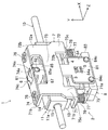
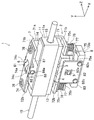
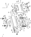
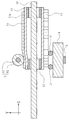
図1は、実施形態に係る駆動装置の斜視図を、図2は、駆動装置を図1とは別の角度から観た斜視図を、図3は、駆動装置の分解斜視図を示す。尚、図中のX軸は、後述する移動体11の移動方向と一致し、Y軸は、後述するアクチュエータ本体4及びローラ6の付勢方向と一致し、Z軸は、該移動方向及び付勢方向の両方に直交する方向と一致する。図10〜14においても同様である。実施形態に係る駆動装置1は、図1〜3に示すように、基台(図示省略)に固定されたシャフト10と、該シャフト10に摺動自在に設けられた移動体11と、該移動体11を駆動する超音波アクチュエータ2と、該基台に対して固定され、該超音波アクチュエータ2を支持する支持体8と、該超音波アクチュエータ2を駆動制御する制御装置(図示省略)とを備えている。   FIG. 1 is a perspective view of the drive device according to the embodiment, FIG. 2 is a perspective view of the drive device viewed from a different angle from FIG. 1, and FIG. 3 is an exploded perspective view of the drive device. In the figure, the X axis coincides with the moving direction of the moving body 11 described later, the Y axis coincides with the urging direction of the actuator body 4 and the roller 6 described later, and the Z axis indicates the moving direction and the attaching direction. It coincides with the direction perpendicular to both the force directions. The same applies to FIGS. As shown in FIGS. 1 to 3, the drive device 1 according to the embodiment includes a shaft 10 fixed to a base (not shown), a movable body 11 slidably provided on the shaft 10, and the movement An ultrasonic actuator 2 that drives the body 11, a support 8 that is fixed to the base and supports the ultrasonic actuator 2, and a control device (not shown) that drives and controls the ultrasonic actuator 2. I have.

移動体11は、四角柱状であって、その軸方向に貫通孔11b(図10にのみ図示)が貫通形成された移動体本体11aと、貫通孔11bの両端部に設けられた軸受部15(図1〜3では、それぞれ1つだけ図示)と、後述するアクチュエータ本体4が当接する第1摺動板13と、後述するローラ6が当接する第2摺動板14とを有している。軸受部15は、貫通孔11bに圧入又は接着固定されている。この軸受部15に、シャフト10が挿通される。こうして、移動体11は、シャフト10の軸方向(図中のX軸方向)に沿って摺動可能に構成されている。このシャフト10の延びる方向が移動体11の可動方向となる。この移動体11は、詳しくは後述するが、超音波アクチュエータ2が発生する駆動力を受けて、シャフト10に沿って移動する。   The movable body 11 has a quadrangular prism shape, and a movable body main body 11a in which a through hole 11b (shown only in FIG. 10) is formed so as to penetrate in the axial direction thereof, and bearing portions 15 (provided at both ends of the through hole 11b). 1 to 3, only one is shown), a first sliding plate 13 with which an actuator body 4 described later contacts, and a second sliding plate 14 with which a roller 6 described later contacts. The bearing portion 15 is press-fitted or fixed to the through hole 11b. The shaft 10 is inserted through the bearing portion 15. Thus, the moving body 11 is configured to be slidable along the axial direction of the shaft 10 (X-axis direction in the drawing). The extending direction of the shaft 10 is the movable direction of the moving body 11. As will be described in detail later, the moving body 11 moves along the shaft 10 in response to a driving force generated by the ultrasonic actuator 2.

ここで、移動体本体11aは、例えば、ガラス繊維を含有するポリカーボネートで構成されている。ガラス繊維は、ポリカーボネートの剛性を高めるために添加されている。一般的な、ガラス繊維を含有するポリカーボネートのヤング率は、3.4〜8.8GPaである。また、軸受部15は、例えば、摺動性に優れた含油軸受である。軸受部15は、例えば、焼結により製造される。軸受部15のヤング率は、例えば、約54GPaである。すなわち、軸受部15は、移動体本体11aよりもヤング率、即ち、弾性係数が大きい。   Here, the mobile body 11a is made of, for example, polycarbonate containing glass fiber. Glass fiber is added to increase the rigidity of the polycarbonate. The general Young's modulus of polycarbonate containing glass fibers is 3.4 to 8.8 GPa. Moreover, the bearing part 15 is an oil-impregnated bearing excellent in slidability, for example. The bearing part 15 is manufactured by sintering, for example. The Young's modulus of the bearing portion 15 is about 54 GPa, for example. That is, the bearing portion 15 has a Young's modulus, that is, an elastic coefficient larger than that of the movable body main body 11a.

第1摺動板13は、例えば、アルミナで構成され、移動体本体11aの4つの側面のうちの一の側面(図1〜3では下面)に接着固定されている。アルミナのヤング率は、概ね250〜400GPaである。第1摺動板13の剛性は、移動体本体11aよりも高くなっている。また、第1摺動板13の厚み(Y軸方向の寸法)は、第2摺動板14の2倍以上の厚さとなっている。こうして、第1摺動板13の曲げ剛性を高くし、移動体本体11aの変形を小さくしている。この第1摺動板13が摺動部材を構成する。   The first sliding plate 13 is made of alumina, for example, and is adhesively fixed to one of the four side surfaces (the lower surface in FIGS. 1 to 3) of the movable body 11a. The Young's modulus of alumina is approximately 250 to 400 GPa. The rigidity of the first sliding plate 13 is higher than that of the movable body main body 11a. Further, the thickness (the dimension in the Y-axis direction) of the first sliding plate 13 is twice or more that of the second sliding plate 14. Thus, the bending rigidity of the first sliding plate 13 is increased, and the deformation of the movable body main body 11a is decreased. The first sliding plate 13 constitutes a sliding member.

一方、第2摺動板14は、例えば、プラスチック材料で構成され、移動体本体11aの4つの側面のうち、第1摺動板13が設けられた側面と対向する側面に接着固定されている。プラスチック材料の例としては、ガラス繊維を含まないポリカーボネートが挙げられる。ポリカーボネートのヤング率は、約2.6GPaである。すなわち、第2摺動板14の弾性係数は、移動体本体11aの弾性係数よりも小さい。また、第2摺動板14の弾性係数は、後述するローラ6の弾性係数よりも小さい。   On the other hand, the second sliding plate 14 is made of, for example, a plastic material, and is adhesively fixed to the side surface facing the side surface on which the first sliding plate 13 is provided, among the four side surfaces of the movable body main body 11a. . Examples of plastic materials include polycarbonate that does not contain glass fibers. The Young's modulus of polycarbonate is about 2.6 GPa. That is, the elastic coefficient of the second sliding plate 14 is smaller than the elastic coefficient of the movable body main body 11a. Further, the elastic coefficient of the second sliding plate 14 is smaller than the elastic coefficient of the roller 6 described later.

尚、第1及び第2摺動板13,14の材質も前述の材質に限られるものではなく、任意の材質を用いて形成することができる。ただし、第2摺動板14の弾性係数は、ローラ6の弾性係数よりも小さくすることが好ましく、移動体本体11aの弾性係数よりも小さくすることがさらに好ましい。   In addition, the material of the first and second sliding plates 13 and 14 is not limited to the aforementioned material, and can be formed using any material. However, the elastic coefficient of the second sliding plate 14 is preferably smaller than that of the roller 6, and more preferably smaller than that of the movable body 11a.

以下に、超音波アクチュエータ2の構成について説明する。超音波アクチュエータ2は、移動体11に当接するように付勢されると共に振動することにより移動体11に駆動力を出力するアクチュエータ本体4と、該アクチュエータ本体4を保持するホルダ5と、アクチュエータ本体4と共に移動体11を挟持するローラ6と、アクチュエータ本体4とローラ6とを弾性的に連結する連結部材7とを備えている。この超音波アクチュエータ2が振動型アクチュエータを構成する。   Below, the structure of the ultrasonic actuator 2 is demonstrated. The ultrasonic actuator 2 is urged to abut on the moving body 11 and vibrates, thereby causing the actuator body 4 to output a driving force to the moving body 11, a holder 5 for holding the actuator body 4, and an actuator body. 4 and a roller 6 that sandwiches the moving body 11, and a connecting member 7 that elastically connects the actuator body 4 and the roller 6. This ultrasonic actuator 2 constitutes a vibration type actuator.

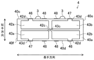
前記アクチュエータ本体4は、圧電素子で構成されている。アクチュエータ本体4は、略長方形状の相対向する一対の主面40a(図3では1つだけ図示)と、この主面40aと直交して該主面40aの長手方向に延びる、相対向する一対の長辺側面40c(図3では1つだけ図示)と、これら主面40a及び長辺側面40cの両方と直交して該主面40aの短手方向に延びる、相対向する一対の短辺側面40e(図3では1つだけ図示)とを有する略直方体状をしている。アクチュエータ本体4には、該アクチュエータ本体4の駆動力を移動体11に伝達する駆動子3,3が設けられている。   The actuator body 4 is composed of a piezoelectric element. The actuator body 4 has a pair of opposing main surfaces 40a (only one is shown in FIG. 3) having a substantially rectangular shape and a pair of opposing main surfaces 40a extending in the longitudinal direction of the main surface 40a perpendicular to the main surface 40a. Long side surface 40c (only one is shown in FIG. 3) and a pair of opposing short side surfaces extending in the short direction of the main surface 40a perpendicular to both the main surface 40a and the long side surface 40c. 40e (only one is illustrated in FIG. 3). The actuator body 4 is provided with driver elements 3 and 3 for transmitting the driving force of the actuator body 4 to the moving body 11.

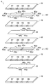
図4に、アクチュエータ本体4の分解斜視図を示す。アクチュエータ本体4は、図4に示すように、圧電体層(圧電素子)41,41,…と内部電極層42,44,43,44とを交互に積層して構成される。内部電極層42,44,43,44は、積層方向に圧電体層41を介して交互に配された、第1給電電極層42と共通電極層44と第2給電電極層43と共通電極層44とを含んでいる。これら第1給電電極層42と共通電極層44と第2給電電極層43と共通電極層44とを1セットとして、複数セットの内部電極層42,44,43,44が圧電体層41を介在させた状態で繰り返し積層されている。尚、積層方向の両端には、圧電体層41,41が位置するようになっている。これら第1給電電極層42、第2給電電極層43及び共通電極層44のそれぞれは、各圧電体層41の主面上に印刷されている。   FIG. 4 shows an exploded perspective view of the actuator body 4. As shown in FIG. 4, the actuator body 4 is configured by alternately laminating piezoelectric layers (piezoelectric elements) 41, 41,... And internal electrode layers 42, 44, 43, 44. The internal electrode layers 42, 44, 43, 44 are alternately arranged via the piezoelectric layers 41 in the stacking direction, the first feeding electrode layer 42, the common electrode layer 44, the second feeding electrode layer 43, and the common electrode layer. 44. The first feeding electrode layer 42, the common electrode layer 44, the second feeding electrode layer 43, and the common electrode layer 44 are set as one set, and a plurality of sets of internal electrode layers 42, 44, 43, 44 interpose the piezoelectric layer 41. In such a state, the layers are repeatedly laminated. The piezoelectric layers 41 are located at both ends in the stacking direction. Each of the first feeding electrode layer 42, the second feeding electrode layer 43, and the common electrode layer 44 is printed on the main surface of each piezoelectric layer 41.

前記各圧電体層41は、例えばチタン酸ジルコン酸鉛などのセラミック材料からなる絶縁体層である。圧電体層41は、前記アクチュエータ本体4と同様に、一対の主面と、一対の長辺側面と、一対の短辺側面とを有する略直方体状をしている。また、各圧電体層41のそれぞれの長辺側面には、長手方向両端部に第1及び第2外部電極46,47が形成され、該第1及び第2外部電極46,47よりも長手方向内側には2つの共通外部電極48,48が形成されている。すなわち、圧電体層41の各長辺側面には、第1外部電極46、共通外部電極48、共通外部電極48、第2外部電極47が、長手方向に沿ってこの順で、互いに間隔を空けて並んでいる。   Each piezoelectric layer 41 is an insulator layer made of a ceramic material such as lead zirconate titanate. Similar to the actuator body 4, the piezoelectric layer 41 has a substantially rectangular parallelepiped shape having a pair of main surfaces, a pair of long side surfaces, and a pair of short side surfaces. In addition, first and second external electrodes 46 and 47 are formed at both ends in the longitudinal direction on the long side surfaces of the piezoelectric layers 41, and are longer than the first and second external electrodes 46 and 47. Two common external electrodes 48 are formed on the inner side. That is, the first external electrode 46, the common external electrode 48, the common external electrode 48, and the second external electrode 47 are spaced apart from each other in this order along the longitudinal direction on each long side surface of the piezoelectric layer 41. Are lined up.

前記各共通電極層44は、圧電体層41の主面の略全面に亘って設けられた略長方形状をしている。また、各共通電極層44のそれぞれの長辺部からは、圧電体層41の長辺側面に形成された共通外部電極48,48まで延びる引出電極44a,44aが形成されている。   Each common electrode layer 44 has a substantially rectangular shape provided over substantially the entire main surface of the piezoelectric layer 41. In addition, lead electrodes 44 a and 44 a extending from the long side portions of the common electrode layers 44 to the common external electrodes 48 and 48 formed on the long side surfaces of the piezoelectric layer 41 are formed.

前記第1及び第2給電電極層42,43は、図5に示すように、圧電体層41の主面をその長手方向及び短手方向にそれぞれ2等分してなる4つの領域のうち該主面の対角線方向に位置する2対の領域のうち一方の対の領域にそれぞれ形成された一対の第1電極42a,42bと、他方の対の領域にそれぞれ形成された一対の第2電極43a,43bとを有する。これら第1電極42a,42b及び第2電極43a,43bは、圧電体層41を挟んで共通電極層44と対向している。また、第1電極42a,42bのそれぞれからは、それらに近接する、圧電体層41の長辺側面に形成された第1外部電極46,46まで延びる引出電極42d,42dが形成されている。第2電極43a,43bのそれぞれからは、それらに近接する、圧電体層41の長辺側面に形成された第2外部電極47,47まで延びる引出電極43d,43dが形成されている。そして、第1給電電極層42においては、第1電極42a,42bが第1導通電極42cを介して導通している。また、第2給電電極層43においては、第2電極43a,43bが第2導通電極43cを介して導通している。   As shown in FIG. 5, the first and second feeding electrode layers 42 and 43 are formed of four regions formed by dividing the main surface of the piezoelectric layer 41 into two equal parts in the longitudinal direction and the short direction, respectively. A pair of first electrodes 42a, 42b formed in one pair of regions of the two pairs of regions located in the diagonal direction of the main surface, and a pair of second electrodes 43a formed in the other pair of regions, respectively. , 43b. The first electrodes 42 a and 42 b and the second electrodes 43 a and 43 b are opposed to the common electrode layer 44 with the piezoelectric layer 41 interposed therebetween. In addition, from each of the first electrodes 42a and 42b, lead electrodes 42d and 42d extending to the first external electrodes 46 and 46 formed on the long side surface of the piezoelectric layer 41 adjacent to them are formed. From each of the second electrodes 43a and 43b, lead electrodes 43d and 43d extending to the second external electrodes 47 and 47 formed on the long side surface of the piezoelectric layer 41 are formed in the vicinity thereof. In the first feeding electrode layer 42, the first electrodes 42a and 42b are conducted through the first conduction electrode 42c. In the second feeding electrode layer 43, the second electrodes 43a and 43b are conducted through the second conduction electrode 43c.

これら圧電体層41,41,…と内部電極層42,44,43,44とを交互に積層することで構成されたアクチュエータ本体4の各長辺側面40c,40dにおいては、各圧電体層41の共通外部電極48,48がそれぞれ積層方向に並んで一まとまりに形成されている。この外部電極48には、前記共通電極層44,44に形成された引出電極44a,44aが電気的に接続されている。こうして、異なる圧電体層41,41,…に設けられた共通電極層44,44,…は、共通外部電極48,48を介して互いに導通している。   The piezoelectric layers 41, 41,... And the internal electrode layers 42, 44, 43, 44 are alternately stacked. The common external electrodes 48, 48 are formed together in the stacking direction. The external electrodes 48 are electrically connected to lead electrodes 44 a and 44 a formed on the common electrode layers 44 and 44. Thus, the common electrode layers 44, 44,... Provided in the different piezoelectric layers 41, 41,... Are electrically connected to each other via the common external electrodes 48, 48.

同様に、アクチュエータ本体4の各長辺側面40c,40dにおいては、各圧電体層41の第1外部電極46が積層方向に並んで一まとまりに形成されていると共に、各圧電体層41の第2外部電極47が積層方向に並んで一まとまりに形成されている。第1外部電極46,46には、前記第1電極42a,42bからの引出電極42d,42dが電気的に接続されている。また、第2外部電極47,47には、前記第2電極43a,43bからの引出電極43d,43dが電気的に接続されている。こうして、第1電極42a,42bは、第1導通電極42c及び第1外部電極46,46を介して、異なる圧電体層41,41,…に設けられた第1電極42a,42bと互いに導通している。また、第2電極43a,43bは、第2導通電極43c及び第2外部電極47,47を介して、異なる圧電体層41,41,…に設けられた第2電極43a,43bと互いに導通している。これら外部電極46,47,48には、制御装置からの信号線が接続される。アクチュエータ本体4は、外部電極46,47,48を介して給電される。   Similarly, on each of the long side surfaces 40c and 40d of the actuator body 4, the first external electrodes 46 of the piezoelectric layers 41 are formed together in the stacking direction, and the first outer electrodes 46 of the piezoelectric layers 41 are arranged together. Two external electrodes 47 are formed as a unit along the stacking direction. Lead electrodes 42d and 42d from the first electrodes 42a and 42b are electrically connected to the first external electrodes 46 and 46, respectively. The second external electrodes 47 and 47 are electrically connected to the extraction electrodes 43d and 43d from the second electrodes 43a and 43b. Thus, the first electrodes 42a, 42b are electrically connected to the first electrodes 42a, 42b provided on the different piezoelectric layers 41, 41,... Via the first conductive electrode 42c and the first external electrodes 46, 46. ing. The second electrodes 43a and 43b are electrically connected to the second electrodes 43a and 43b provided on the different piezoelectric layers 41, 41,... Via the second conductive electrode 43c and the second external electrodes 47 and 47, respectively. ing. A signal line from the control device is connected to these external electrodes 46, 47 and 48. The actuator body 4 is supplied with power through external electrodes 46, 47 and 48.

そして、アクチュエータ本体4の一方の長辺側面(すなわち、後述する屈曲振動の振動方向を向く一対の面のうちの一方の面。以下、設置面ともいう)40cには、2個の駆動子3,3が設けられている。   In addition, one long side surface of the actuator body 4 (that is, one surface of a pair of surfaces facing a vibration direction of bending vibration described later, hereinafter also referred to as an installation surface) 40c includes two driver elements 3. , 3 are provided.

これら駆動子3,3は、断面半円形の柱状の部材であって、ジルコニア、アルミナ、窒化ケイ素、炭化ケイ素、タングステンカーバイド等で形成されている。駆動子3,3は、その軸方向がアクチュエータ本体4の厚み方向を向くように配設されている。駆動子3,3は、設置面40cに対して接着剤を介して面接触状に取り付けられている。   These driver elements 3, 3 are columnar members having a semicircular cross section, and are formed of zirconia, alumina, silicon nitride, silicon carbide, tungsten carbide, or the like. The drive elements 3 and 3 are arranged so that the axial direction thereof faces the thickness direction of the actuator body 4. The driver elements 3 and 3 are attached to the installation surface 40c in a surface contact manner via an adhesive.

また、駆動子3,3が設けられた位置は、設置面40cにおいて、アクチュエータ本体4の長手方向両端部から該設置面40cの全長の30〜35%距離だけ内側に入った位置であり、即ち、アクチュエータ本体4の後述する屈曲振動の2次モードの腹の位置であって、振動が最も大きくなる位置である。   Further, the positions where the driving elements 3 and 3 are provided are positions on the installation surface 40c that are inward from the both longitudinal ends of the actuator body 4 by a distance of 30 to 35% of the total length of the installation surface 40c. The position of the antinode of the secondary mode of bending vibration, which will be described later, of the actuator body 4 is the position where the vibration becomes the largest.

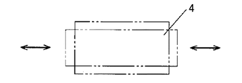
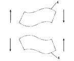
このように構成されたアクチュエータ本体4は、前記外部電極48をグランドに接続し、前記第1及び第2外部電極46,47に所定周波数の交流電圧を位相が90°ずれた状態で印加することによって、圧電体層41の主面の対角線方向に位置する一方の対の第1電極42a,42bと、他方の対の第2電極43a,43bとに互いに位相が90°ずれた交流電圧が印加され、その長手方向への伸縮振動(いわゆる、縦振動)とその短手方向への屈曲振動(いわゆる、横振動)とが誘起される。   The actuator body 4 configured as described above connects the external electrode 48 to the ground and applies an alternating voltage of a predetermined frequency to the first and second external electrodes 46 and 47 in a state where the phase is shifted by 90 °. Thus, an alternating voltage whose phase is shifted by 90 ° is applied to one pair of first electrodes 42a and 42b and the other pair of second electrodes 43a and 43b located in the diagonal direction of the main surface of the piezoelectric layer 41. Then, stretching vibration in the longitudinal direction (so-called longitudinal vibration) and bending vibration in the short direction (so-called transverse vibration) are induced.

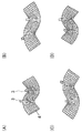
伸縮振動の共振周波数及び屈曲振動の共振周波数は、アクチュエータ本体4の材料、形状等により決定される。さらに、両共振周波数は、アクチュエータ本体4を支持する力及び支持する部分によっても影響を受ける。これらを考慮して両共振周波数を略一致させ、その近傍の周波数の交流電圧を、位相を90°ずらした状態で第1及び第2外部電極46,47のそれぞれに印加する。例えば、伸縮振動の1次モード(図6参照)の共振周波数と屈曲振動の2次モード(図7参照)の共振周波数とが一致するようにアクチュエータ本体4の形状等を設計して、該共振周波数近傍の交流電圧を前述の如く、位相を90°ずらして印加することによって、アクチュエータ本体4には、伸縮振動の1次モードと屈曲振動の2次モードとが調和的に誘起され、図8(A)、(B)、(C)、(D)に示す形状の変化を順番に起こす。   The resonance frequency of the stretching vibration and the resonance frequency of the bending vibration are determined by the material, shape, and the like of the actuator body 4. Furthermore, both resonance frequencies are also affected by the force and the supporting portion that support the actuator body 4. Considering these, both resonance frequencies are substantially matched, and an alternating voltage having a frequency in the vicinity thereof is applied to each of the first and second external electrodes 46 and 47 with the phase shifted by 90 °. For example, the shape of the actuator body 4 is designed so that the resonance frequency of the primary mode of stretching vibration (see FIG. 6) matches the resonance frequency of the secondary mode of bending vibration (see FIG. 7), and the resonance By applying an alternating voltage in the vicinity of the frequency with a phase shifted by 90 ° as described above, a primary mode of stretching vibration and a secondary mode of bending vibration are induced in the actuator body 4 in a harmonic manner. The shape changes shown in (A), (B), (C), and (D) occur in order.

その結果、アクチュエータ本体4に設けられた各駆動子3が該アクチュエータ本体4の主面と平行な平面(図7における紙面と平行な面)、即ち、長手方向と短手方向とを含む平面(さらに換言すれば、伸縮振動の振動方向と屈曲振動の振動方向とを含む平面)内で略楕円運動、即ち、周回運動を行う。   As a result, each driver element 3 provided in the actuator body 4 is a plane parallel to the main surface of the actuator body 4 (a plane parallel to the paper surface in FIG. 7), that is, a plane including a longitudinal direction and a lateral direction ( In other words, a substantially elliptical motion, that is, a circular motion is performed within a plane including the vibration direction of the stretching vibration and the vibration direction of the bending vibration.

このように構成されたアクチュエータ本体4は、駆動子3,3が移動体11の第1摺動板13に当接する状態で配設される。   The actuator body 4 configured as described above is disposed in a state in which the driver elements 3 are in contact with the first sliding plate 13 of the moving body 11.

ホルダ5は、ポリカーボネート(ガラス繊維入り)で構成された、四角柱状の部材である。ホルダ5は、アクチュエータ本体4の駆動子3,3が設けられていない方の長辺側面に設けられている。ホルダ5は、アクチュエータ本体4の長手方向中央において厚み方向(即ち、積層方向)に延びるようにして、該長辺側面に、例えば接着剤を介して取り付けられている。ホルダ5の両端部は、アクチュエータ本体4の両主面から厚み方向に突き出ている。   The holder 5 is a quadrangular prism-shaped member made of polycarbonate (with glass fiber). The holder 5 is provided on the long side surface of the actuator body 4 where the driver elements 3 are not provided. The holder 5 is attached to the side surface of the long side via, for example, an adhesive so as to extend in the thickness direction (that is, the stacking direction) at the longitudinal center of the actuator body 4. Both end portions of the holder 5 protrude in the thickness direction from both main surfaces of the actuator body 4.

ローラ6は、ローラ本体61と、ローラシャフト62とを有している。ローラ本体61は、ボールベアリングを介してローラシャフト62に回転自在に取り付けられている。このローラ6が、対向部材を構成する。このローラ6は、移動体11に当接すると共に該移動体11を挟んでアクチュエータ本体4と対向する位置に位置する。ローラ本体61及びローラシャフト62は、剛性を高めるためにSUS304やSUS410といったステンレス合金で形成されている。ステンレス合金のヤング率は、約200GPaである。   The roller 6 has a roller body 61 and a roller shaft 62. The roller body 61 is rotatably attached to the roller shaft 62 via a ball bearing. This roller 6 constitutes a counter member. The roller 6 is in contact with the moving body 11 and is located at a position facing the actuator body 4 with the moving body 11 interposed therebetween. The roller body 61 and the roller shaft 62 are made of a stainless alloy such as SUS304 or SUS410 in order to increase rigidity. The Young's modulus of the stainless alloy is about 200 GPa.

連結部材7は、連結部材本体70と、該連結部材本体70に取り付けられてローラ6を移動体11に押圧するための押圧板74と、該連結部材本体70に取り付けられてアクチュエータ本体4を移動体11に押圧するための板バネ75とを有している。連結部材7は、アクチュエータ本体4とローラ6とを連結すると共に、該アクチュエータ本体4とローラ6とが移動体11を押圧するように該アクチュエータ本体4とローラ6とを付勢している。   The connecting member 7 includes a connecting member main body 70, a pressing plate 74 attached to the connecting member main body 70 to press the roller 6 against the moving body 11, and attached to the connecting member main body 70 to move the actuator main body 4. And a leaf spring 75 for pressing against the body 11. The connecting member 7 connects the actuator body 4 and the roller 6 and urges the actuator body 4 and the roller 6 so that the actuator body 4 and the roller 6 press the moving body 11.

連結部材本体70は、アクチュエータ本体4の短手方向に互いに平行に延びる第1連結部71及び第2連結部72と、アクチュエータ本体4の長手方向に延びて該第1及び第2連結部71,72を連結する第3連結部73とを有している。   The connecting member body 70 includes a first connecting portion 71 and a second connecting portion 72 that extend in parallel with each other in the short direction of the actuator body 4, and a first connecting portion 71 that extends in the longitudinal direction of the actuator body 4. And a third connecting portion 73 that connects the second and second connecting portions 72.

第1連結部71は、アクチュエータ本体4の短手方向へ平坦に延びる本体部71aと、該本体部71aの両端部から本体部71aに対して略垂直に屈曲する取付部71b,71bとを有している。第2連結部72は、第1連結部71と同様の形状をしており、本体部72aと、取付部72b,72bとを有している。取付部71b,72bには、それぞれネジ孔71c,72c(図3にのみ図示)が貫通形成されている。第1連結部71の一方の取付部71b及び第2連結部72の一方の取付部72bは、移動体11の第2摺動板14と対向し、第1連結部71の他方の取付部71b及び第2連結部72の他方の取付部72bは、移動体11の第1摺動板13と対向する。第3連結部73は、第1連結部71の本体部71aと、第2連結部72の本体部72aとを連結している。第3連結部73は、第1連結部71の本体部71aや第2連結部72の本体部72aと同一平面上を延びるのではなく、本体部71a及び本体部72aよりも取付部71b,72bとは反対側に浮き上がっている。これら第1〜第3連結部71〜73は、平板を屈曲させて一体に形成されており、全体としてH字状に形成されている。   The first connecting portion 71 has a main body portion 71a that extends flat in the short direction of the actuator main body 4, and attachment portions 71b and 71b that bend substantially perpendicularly to the main body portion 71a from both ends of the main body portion 71a. is doing. The 2nd connection part 72 has the same shape as the 1st connection part 71, and has the main-body part 72a and the attaching parts 72b and 72b. Screw holes 71c and 72c (shown only in FIG. 3) are formed through the attachment portions 71b and 72b, respectively. One attachment portion 71 b of the first connection portion 71 and one attachment portion 72 b of the second connection portion 72 are opposed to the second sliding plate 14 of the moving body 11, and the other attachment portion 71 b of the first connection portion 71. The other attachment portion 72 b of the second connecting portion 72 faces the first sliding plate 13 of the moving body 11. The third connecting part 73 connects the main body part 71 a of the first connecting part 71 and the main body part 72 a of the second connecting part 72. The third connecting portion 73 does not extend on the same plane as the main body portion 71a of the first connecting portion 71 and the main body portion 72a of the second connecting portion 72, but rather than the main body portion 71a and the main body portion 72a. It floats on the opposite side. The first to third connecting portions 71 to 73 are integrally formed by bending a flat plate, and are formed in an H shape as a whole.

押圧板74は、略長方形状の平板で構成されている。押圧板74は、その長手方向中央に長方形の貫通孔74aが、長手方向両端部に円形の挿通孔74b,74b(図3にのみ図示)が貫通形成されている。押圧板74は、第1及び第2連結部71,72の、第2摺動板14と対向する側の取付部71b,72bにネジ締結される。詳しくは、押圧板74の挿通孔74b,74bに挿通されたネジ76,76がそれぞれ、取付部71bのネジ孔71c及び取付部72bのネジ孔72cに締結されることによって、押圧板74が第1及び第2連結部71,72に取り付けられる。尚、押圧板74は、第1及び第2連結部71,72と一体に構成してもよい。   The pressing plate 74 is a substantially rectangular flat plate. In the pressing plate 74, a rectangular through hole 74a is formed in the center in the longitudinal direction, and circular insertion holes 74b and 74b (shown only in FIG. 3) are formed through both ends in the longitudinal direction. The pressing plate 74 is screwed to the mounting portions 71b and 72b on the side of the first and second connecting portions 71 and 72 facing the second sliding plate 14. Specifically, the screws 76, 76 inserted through the insertion holes 74b, 74b of the pressing plate 74 are fastened to the screw holes 71c of the mounting portion 71b and the screw holes 72c of the mounting portion 72b, respectively. The first and second connecting portions 71 and 72 are attached. Note that the pressing plate 74 may be configured integrally with the first and second connecting portions 71 and 72.

このとき、押圧板74と移動体11とでローラ6を挟持している。詳しくは、ローラ本体61は、押圧板74の貫通孔74a内に位置し、該貫通孔74aから突出している。このとき、ローラ6のローラシャフト62は、押圧板74と接触しており、押圧板74により移動体11側へ押圧されている。その結果、ローラ本体61が移動体11の第2摺動板14に押し付けられる。尚、押圧板74の長辺における、長手方向中央には、その短手方向に突出する突起部74c,74cが設けられている。   At this time, the roller 6 is held between the pressing plate 74 and the movable body 11. Specifically, the roller body 61 is located in the through hole 74a of the pressing plate 74 and protrudes from the through hole 74a. At this time, the roller shaft 62 of the roller 6 is in contact with the pressing plate 74 and is pressed toward the moving body 11 by the pressing plate 74. As a result, the roller body 61 is pressed against the second sliding plate 14 of the moving body 11. In the long side of the pressing plate 74, projections 74c and 74c projecting in the short direction are provided at the center in the longitudinal direction.

板バネ75は、板金を折り曲げて構成されている。詳しくは、板バネ75は、アクチュエータ本体4の長辺側面と平行な底板部75aと、底板部75aの両端部から立設され、アクチュエータ本体4の短辺側面と平行な縦板部75b,75bと、縦板部75b,75bの先端から外側へ底板部75aと平行に延びるフランジ部75c,75cとを有している。板バネ75は、アクチュエータ本体4の、ホルダ5が設けられた長辺側面及び2つの短辺側面を外側から覆うように、全体として凹形状をしている。各フランジ部75cには、後述するネジを挿通させる挿通孔75dが貫通形成されている。   The leaf spring 75 is configured by bending a sheet metal. More specifically, the leaf spring 75 is erected from a bottom plate portion 75 a parallel to the long side surface of the actuator body 4 and both end portions of the bottom plate portion 75 a, and vertical plate portions 75 b and 75 b parallel to the short side surface of the actuator body 4. And flange portions 75c and 75c extending in parallel with the bottom plate portion 75a from the front ends of the vertical plate portions 75b and 75b to the outside. The leaf spring 75 has a concave shape as a whole so as to cover the long side surface on which the holder 5 is provided and the two short side surfaces of the actuator body 4 from the outside. Each flange portion 75c is formed with an insertion hole 75d through which a screw described later is inserted.

この板バネ75は、第1及び第2連結部71,72の、第1摺動板13と対向する側の取付部71b,72bにネジ締結される。詳しくは、板バネ75の挿通孔75d,75dに挿通された段付ネジ77,77がそれぞれ、取付部71bのネジ孔71c及び取付部72bのネジ孔72cに締結されることによって、板バネ75が第1及び第2連結部71,72に取り付けられる。このとき、段付ネジ77には、コイルバネ78が外嵌されている。このコイルバネ78は、段付ネジ77の頭と板バネ75とに挟持されて圧縮変形している。こうして連結部材7に取り付けられる板バネ75は、移動体11との間にアクチュエータ本体4を収容し、移動体11との間で該アクチュエータ本体4を挟持している。詳しくは、板バネ75の底板部75aがアクチュエータ本体4に設けられたホルダ5と当接している。その結果、圧縮変形したコイルバネ78の弾性力が板バネ75及びホルダ5を介してアクチュエータ本体4を移動体11側へ付勢する。その結果、アクチュエータ本体4は、移動体11の第1摺動板13を押圧する。すなわち、これら板バネ75、段付ネジ77及びコイルバネ78が付勢部として機能する。   The leaf spring 75 is screwed to the attachment portions 71b and 72b of the first and second connecting portions 71 and 72 on the side facing the first sliding plate 13. Specifically, the stepped screws 77 and 77 inserted through the insertion holes 75d and 75d of the leaf spring 75 are respectively fastened to the screw holes 71c of the attachment portion 71b and the screw holes 72c of the attachment portion 72b. Are attached to the first and second connecting portions 71, 72. At this time, a coil spring 78 is externally fitted to the stepped screw 77. The coil spring 78 is sandwiched between the head of the stepped screw 77 and the leaf spring 75 and is compressed and deformed. The leaf spring 75 thus attached to the connecting member 7 accommodates the actuator body 4 between the movable body 11 and sandwiches the actuator body 4 with the movable body 11. Specifically, the bottom plate portion 75 a of the leaf spring 75 is in contact with the holder 5 provided in the actuator body 4. As a result, the elastic force of the compression-deformed coil spring 78 biases the actuator body 4 toward the movable body 11 via the leaf spring 75 and the holder 5. As a result, the actuator body 4 presses the first sliding plate 13 of the moving body 11. That is, the plate spring 75, the stepped screw 77, and the coil spring 78 function as an urging portion.

それに加えて、コイルバネ78の弾性力は、段付ネジ77を介して連結部材7にも伝達し、さらに連結部材7及び押圧板74を介してローラ6に伝達する。つまり、コイルバネ78の弾性力は、ローラ6を移動体11側へ付勢する。その結果、ローラ6は、移動体11の第2摺動板14を押圧する。   In addition, the elastic force of the coil spring 78 is also transmitted to the connecting member 7 via the stepped screw 77 and further transmitted to the roller 6 via the connecting member 7 and the pressing plate 74. That is, the elastic force of the coil spring 78 urges the roller 6 toward the moving body 11. As a result, the roller 6 presses the second sliding plate 14 of the moving body 11.

このように、超音波アクチュエータ2では、連結部材7によって連結されたアクチュエータ本体4とローラ6とが移動体11を挟持した状態で該移動体11を押圧している。こうして、アクチュエータ本体4の駆動子3,3と移動体11との間には、コイルバネ78の弾性力に応じた摩擦力が生じている。その結果、駆動子3,3から出力される駆動力を移動体11に効率良く伝達することができる。そして、このように駆動子3,3を移動体11に押圧する構成であっても、移動体11は駆動子3,3と反対側から駆動子3,3の押圧力と同様の押圧力でローラ6により押圧されているため、移動体11に作用する押圧力は相殺される。その結果、シャフト10に、偏った不要な力が作用することを防止することができ、移動体11を円滑に移動させることができる。   As described above, in the ultrasonic actuator 2, the actuator body 4 and the roller 6 connected by the connecting member 7 press the moving body 11 with the moving body 11 sandwiched therebetween. Thus, a frictional force corresponding to the elastic force of the coil spring 78 is generated between the driver elements 3, 3 of the actuator body 4 and the moving body 11. As a result, the driving force output from the driver elements 3 and 3 can be efficiently transmitted to the moving body 11. And even if it is the structure which presses the drive elements 3 and 3 to the moving body 11 in this way, the moving body 11 is the same pressing force as the pressing force of the driving elements 3 and 3 from the opposite side to the driving elements 3 and 3. Since it is pressed by the roller 6, the pressing force acting on the moving body 11 is canceled out. As a result, it is possible to prevent the biased unnecessary force from acting on the shaft 10 and to move the moving body 11 smoothly.

次に、支持体8の構成について説明する。支持体8は、アクチュエータ本体4を支持する第1及び第2支持板81,82と、第1及び第2支持板81,82が取り付けられると共に基台に固定されるベース部材83とを有している。この支持体8が支持部を構成する。   Next, the configuration of the support 8 will be described. The support 8 includes first and second support plates 81 and 82 that support the actuator body 4, and a base member 83 to which the first and second support plates 81 and 82 are attached and fixed to the base. ing. This support body 8 constitutes a support portion.

ベース部材83は、ブロック状の部材であって、基台にネジ締結される。また、ベース部材83には、第1及び第2支持板81,82を取り付けるためのネジ孔83a,83a(図3に2つだけ図示)が形成されている。   The base member 83 is a block-shaped member, and is screwed to the base. Further, screw holes 83a and 83a (only two are shown in FIG. 3) for attaching the first and second support plates 81 and 82 are formed in the base member 83.

第1支持板81は、屈曲した板状の部材で構成されている。第1支持板81は、方形の基端部84と、基端部84から延びる延設部85と、延設部85の先端部に対向して設けられた対向ガイド部86と、該延設部85と対向ガイド部86とを連結する連結部87とを有している。   The first support plate 81 is configured by a bent plate-like member. The first support plate 81 includes a rectangular base end portion 84, an extension portion 85 extending from the base end portion 84, an opposing guide portion 86 provided to face the tip end portion of the extension portion 85, and the extension It has the connection part 87 which connects the part 85 and the opposing guide part 86. FIG.

また、基端部84の中央には、開口部84aが厚み方向に貫通形成されている。この開口部84aに、ホルダ5を支持するためのガイド部材88(図3では1つだけ図示)が設けられる。ガイド部材88は、基端部84に接着固定されている。ガイド部材88には、アクチュエータ本体4を移動体11へ付勢する方向(即ち、アクチュエータ本体4の短手方向であって、図中のY軸方向)に延びる長孔状のガイド孔88aが貫通形成されている。ガイド孔88aは、ホルダ5の幅よりも少し余裕のある幅を有している。ガイド孔88aには、ホルダ5の、アクチュエータ本体4の厚み方向に突出する端部が挿入される。ホルダ5の端部は、ガイド孔88a内をガイド孔88aの延伸方向に摺動することができる。ガイド部材88は、基端部84よりも弾性率が小さく、又硬度が小さい材料で構成されている。また、ガイド部材88は、ホルダ5よりも軟質で、しかも樹脂などに対して摺動性に優れる材料で構成されている。例えば、ガイド部材88は、ポリアセタールで構成されている。尚、ホルダ5の突出量によっては、ガイド孔88aはガイド部材88を貫通せず、有底状であってもよい。また、基端部84の四隅のうち、延設部85が設けられた辺と反対側の辺の両端に位置する2つの隅部にはそれぞれ、挿通孔84bが貫通形成されている。これら挿通孔84b,84bにネジ84c,84cを挿通し、該ネジ84c,84cをベース部材83のネジ孔83a,83aに締結することによって、第1支持板81がベース部材83に取り付けられる。   In addition, an opening 84a is formed through the center end portion 84 in the thickness direction. A guide member 88 (only one is shown in FIG. 3) for supporting the holder 5 is provided in the opening 84a. The guide member 88 is bonded and fixed to the base end portion 84. The guide member 88 has a long hole-like guide hole 88a extending in a direction in which the actuator body 4 is urged toward the moving body 11 (that is, the short direction of the actuator body 4 and the Y-axis direction in the drawing). Is formed. The guide hole 88 a has a width that is slightly larger than the width of the holder 5. The end of the holder 5 that protrudes in the thickness direction of the actuator body 4 is inserted into the guide hole 88a. The end of the holder 5 can slide in the guide hole 88a in the extending direction of the guide hole 88a. The guide member 88 is made of a material having a smaller elastic modulus and a lower hardness than the base end portion 84. Further, the guide member 88 is made of a material that is softer than the holder 5 and that is excellent in slidability with respect to resin or the like. For example, the guide member 88 is made of polyacetal. Depending on the amount of protrusion of the holder 5, the guide hole 88 a does not penetrate the guide member 88 and may have a bottomed shape. Further, among the four corners of the base end portion 84, insertion holes 84b are formed through the two corner portions located at both ends of the side opposite to the side where the extending portion 85 is provided. The first support plate 81 is attached to the base member 83 by inserting the screws 84 c and 84 c into the insertion holes 84 b and 84 b and fastening the screws 84 c and 84 c to the screw holes 83 a and 83 a of the base member 83.

延設部85は、基端部84の一辺から、ガイド孔88aの延設方向と同じ方向に延びている。延設部85の先端には、ガイド溝85aとなる切り込みが形成されている。すなわち、延設部85の先端は、二股状に形成されている。このガイド溝85aの延びる方向と基端部84のガイド孔88aの延びる方向とは一致している。すなわち、ガイド溝85aとガイド孔88aとは、一直線上に配置されている。   The extending portion 85 extends from one side of the base end portion 84 in the same direction as the extending direction of the guide hole 88a. A notch serving as a guide groove 85a is formed at the tip of the extended portion 85. That is, the tip of the extending portion 85 is formed in a bifurcated shape. The direction in which the guide groove 85a extends coincides with the direction in which the guide hole 88a in the base end portion 84 extends. That is, the guide groove 85a and the guide hole 88a are arranged on a straight line.

対向ガイド部86は、延設部85の先端部と同様に、ガイド溝86aとなる切り込みが形成され、二股状に形成されている。この対向ガイド部86は、延設部85の先端部と対向する状態で、連結部87を介して該先端部に連結されている。   The opposing guide portion 86 is formed in a bifurcated shape with a notch that becomes a guide groove 86a, similarly to the distal end portion of the extending portion 85. The opposing guide portion 86 is coupled to the distal end portion via a coupling portion 87 in a state of facing the distal end portion of the extending portion 85.

ガイド溝85a,86aは、ローラ6のローラシャフト62の外径よりも少し余裕のある幅を有しており、ローラシャフト62が嵌るように構成されている。また、ガイド溝85a,86aには、ローラシャフト62に加えて、押圧板74の突起部74c,74cが嵌るように構成されている。   The guide grooves 85 a and 86 a have a width that is slightly larger than the outer diameter of the roller shaft 62 of the roller 6, and are configured to fit the roller shaft 62. In addition to the roller shaft 62, the protrusions 74c and 74c of the pressing plate 74 are configured to fit into the guide grooves 85a and 86a.

また、第2支持板82は、略長方形状の平板状の部材で構成されている。第2支持板82の略中央には、開口部82aが厚み方向に貫通形成されている。この開口部82aに、ホルダ5を支持するためのガイド部材(図示省略)が設けられる。このガイド部材は、第1支持板81のガイド部材88と同じ構成をしている。すなわち、ガイド部材には、アクチュエータ本体4を移動体11へ付勢する方向に延びる長孔状のガイド孔が貫通形成されている。このガイド孔には、ホルダ5の、アクチュエータ本体4の厚み方向に突出する端部が挿入される。ホルダ5の端部は、ガイド孔内をガイド孔の延伸方向に摺動することができる。アクチュエータ本体4の短手方向に延びる略長方形のガイド孔が貫通形成されている。ガイド孔は、ホルダ5の幅よりも少し余裕のある幅を有しており、ホルダ5が嵌るように構成されている。また、第2支持板82の四隅のうち、一方の長辺の両端に位置する2つの隅部にはそれぞれ、挿通孔82b,82bが貫通形成されている。これら挿通孔82b,82bにネジ82c,82cを挿通し、該ネジ82c,82cをベース部材83のネジ孔83a,83aに締結することによって、第2支持板82がベース部材83に取り付けられる。第2支持板82をベース部材83に取り付けたとき、開口部82aに設けられたガイド部材のガイド孔は、第1支持板81の対向ガイド部86のガイド溝86aと一直線上に配置される。   The second support plate 82 is formed of a substantially rectangular flat plate member. An opening 82a is formed in the center of the second support plate 82 in the thickness direction. A guide member (not shown) for supporting the holder 5 is provided in the opening 82a. This guide member has the same configuration as the guide member 88 of the first support plate 81. In other words, the guide member is formed with a long hole-like guide hole extending in a direction in which the actuator body 4 is urged toward the moving body 11. The end of the holder 5 that protrudes in the thickness direction of the actuator body 4 is inserted into the guide hole. The end of the holder 5 can slide in the guide hole in the extending direction of the guide hole. A substantially rectangular guide hole extending in the short direction of the actuator body 4 is formed through. The guide hole has a width that is slightly larger than the width of the holder 5, and is configured to fit the holder 5. Further, through holes 82 b and 82 b are formed through two corners located at both ends of one long side among the four corners of the second support plate 82. The second support plate 82 is attached to the base member 83 by inserting the screws 82 c and 82 c into the insertion holes 82 b and 82 b and fastening the screws 82 c and 82 c to the screw holes 83 a and 83 a of the base member 83. When the second support plate 82 is attached to the base member 83, the guide hole of the guide member provided in the opening 82 a is arranged in line with the guide groove 86 a of the opposing guide portion 86 of the first support plate 81.

このように、支持体8は、超音波アクチュエータ2のホルダ5を第1及び第2支持板81,82の開口部84a,82aに設けたガイド部材88のガイド孔88aで支持すると共に、超音波アクチュエータ2のローラシャフト62を第1支持板81のガイド溝85a,86aで支持する。これら第1及び第2支持板81,82がガイド部を、ガイド孔88aが長孔を、ガイド溝85a,86aが溝を構成し、ホルダ5及びローラシャフト62が係合部を構成する。   As described above, the support 8 supports the holder 5 of the ultrasonic actuator 2 through the guide hole 88a of the guide member 88 provided in the openings 84a and 82a of the first and second support plates 81 and 82, and ultrasonic waves. The roller shaft 62 of the actuator 2 is supported by the guide grooves 85 a and 86 a of the first support plate 81. The first and second support plates 81 and 82 constitute a guide portion, the guide hole 88a constitutes a long hole, the guide grooves 85a and 86a constitute a groove, and the holder 5 and the roller shaft 62 constitute an engagement portion.

ここで、ホルダ5が嵌るガイド孔88aと、ローラシャフト62が嵌るガイド溝85a,86aとは、アクチュエータ本体4の厚み方向を向かって見たときに一直線上に配置されているため、ローラ6と移動体11との当接部分は、シャフト10の軸方向において、2つの駆動子3,3と移動体11との当接部の中間地点と一致している。すなわち、ローラ6及びアクチュエータ本体4で移動体11を挟み込む押圧力は、ローラ6と移動体11との当接部分を通り且つローラ6及びアクチュエータ本体4で挟み込む方向(即ち、アクチュエータ本体4の短手方向)に延びる直線に対して線対称に作用する。   Here, since the guide hole 88a in which the holder 5 fits and the guide grooves 85a and 86a in which the roller shaft 62 fits are arranged in a straight line when viewed in the thickness direction of the actuator body 4, A contact portion with the moving body 11 coincides with an intermediate point of a contact portion between the two driving elements 3 and 3 and the moving body 11 in the axial direction of the shaft 10. That is, the pressing force for sandwiching the moving body 11 between the roller 6 and the actuator body 4 passes through the contact portion between the roller 6 and the moving body 11 and is sandwiched between the roller 6 and the actuator body 4 (that is, the short side of the actuator body 4). Acting in line symmetry with respect to a straight line extending in the direction).

このように構成された駆動装置1の動作は、制御装置によって制御される。詳しくは、制御装置は、外部からの動作指令を受けて、その動作指令に応じた周波数の交流電圧を動作指令に応じた位相差で第1及び第2外部電極46,47に印加する。こうして、制御装置は、アクチュエータ本体4に伸縮振動と屈曲振動とを調和的に発生させて、駆動子3,3を図8に示すように周回運動させる。このとき、駆動子3,3は、連結部材7により移動体11に付勢されており、駆動子3,3と移動体11との間には十分な摩擦力が作用している。その結果、摩擦力を介して、移動体11がシャフト10に沿って駆動される。尚、移動体11の第2摺動板14にはローラ6が駆動子3,3の摩擦力と同等の摩擦力で当接しているが、ローラ本体61はボールベアリングを介して回転するため、ローラ6が移動体11の移動を妨げることはない。   Operation | movement of the drive device 1 comprised in this way is controlled by the control apparatus. Specifically, the control device receives an operation command from the outside and applies an alternating voltage having a frequency corresponding to the operation command to the first and second external electrodes 46 and 47 with a phase difference corresponding to the operation command. In this way, the control device causes the actuator body 4 to generate stretching vibration and bending vibration in a harmonious manner, thereby causing the driver elements 3 and 3 to move around as shown in FIG. At this time, the driving elements 3 and 3 are urged to the moving body 11 by the connecting member 7, and a sufficient frictional force acts between the driving elements 3 and 3 and the moving body 11. As a result, the moving body 11 is driven along the shaft 10 via the frictional force. The roller 6 is in contact with the second sliding plate 14 of the moving body 11 with a frictional force equivalent to the frictional force of the driver elements 3 and 3, but the roller body 61 rotates through a ball bearing. The roller 6 does not hinder the movement of the moving body 11.

尚、制御装置は、アクチュエータ本体4の異常発熱を防止すべく、アクチュエータ本体4の伸縮振動と屈曲振動との共通の共振周波数よりも少し高い周波数の交流電圧を第1及び第2外部電極46,47に印加する。このとき、かかる交流電圧は、互いに位相が90°ずれた状態で第1及び第2外部電極46,47に印加される。   In order to prevent abnormal heat generation of the actuator body 4, the control device applies an AC voltage having a frequency slightly higher than the common resonance frequency of the expansion and contraction vibration and the bending vibration of the actuator body 4 to the first and second external electrodes 46, 47 is applied. At this time, the AC voltage is applied to the first and second external electrodes 46 and 47 in a state where the phases are shifted from each other by 90 °.

移動体11の駆動について、さらに詳しく説明する。駆動子3,3が略楕円運動を行うと、駆動子3,3と移動体11の第1摺動板13との間の摩擦力の増減が周期的に繰り返される。このとき、アクチュエータ本体4の長手方向への駆動力が摩擦力を介して移動体11に伝達され、移動体11はシャフト10に沿って移動する。このアクチュエータ本体4の長手方向(シャフト10が延びる方向と一致する)が、駆動子3,3が駆動力を出力する方向である駆動方向に相当する。尚、アクチュエータ本体4には、駆動力とは長手方向反対向きの反力が移動体11から作用する。しかし、アクチュエータ本体4に取り付けられたホルダ5がガイド孔88aに係合しているため、該反力は第1及び第2支持板81,82で受け止められる。そのため、アクチュエータ本体4は、駆動力を移動体11へ適切に出力することができる。   The driving of the moving body 11 will be described in more detail. When the driving elements 3 and 3 perform a substantially elliptical motion, the increase and decrease of the frictional force between the driving elements 3 and 3 and the first sliding plate 13 of the moving body 11 is periodically repeated. At this time, the driving force in the longitudinal direction of the actuator body 4 is transmitted to the moving body 11 via the frictional force, and the moving body 11 moves along the shaft 10. The longitudinal direction of the actuator body 4 (which coincides with the direction in which the shaft 10 extends) corresponds to the driving direction in which the driver elements 3 and 3 output the driving force. Note that a reaction force acting in the direction opposite to the driving force from the moving body 11 acts on the actuator body 4. However, since the holder 5 attached to the actuator body 4 is engaged with the guide hole 88 a, the reaction force is received by the first and second support plates 81 and 82. Therefore, the actuator body 4 can appropriately output the driving force to the moving body 11.

さらに詳しくは、アクチュエータ本体4が長手方向(伸縮振動の振動方向)に伸張するとき、一方(例えば、図9の左側)の駆動子3は、図9(B)に示すように、移動体11との間の摩擦力を駆動前の状態(即ち、単に設置しただけの状態)よりも増大させながら変位するため、この摩擦力によって移動体11を該長手方向における該一方の駆動子3が変位する側(図9の左側)へ移動させる。このとき、他方(図9の右側)の駆動子3は、該長手方向において一方の駆動子3とは逆向きに変位するが、該駆動子3は移動体11から離れた状態で変位するか、又は移動体11との間の摩擦力を駆動前の状態よりも減少させながら変位するため、移動体11の移動にはほとんど影響を与えない。   More specifically, when the actuator body 4 extends in the longitudinal direction (vibration direction of the stretching vibration), the driver element 3 on one side (for example, the left side in FIG. 9) is moved to the movable body 11 as shown in FIG. 9B. Is displaced while increasing the frictional force between the first and second driving elements 3 in the longitudinal direction by the frictional force. To the side (left side in FIG. 9). At this time, the other driver element 3 (right side in FIG. 9) is displaced in the longitudinal direction opposite to the one driver element 3, but is the driver element 3 displaced in a state of being separated from the moving body 11? In addition, since the displacement is performed while the frictional force between the movable body 11 and the movable body 11 is reduced as compared with the state before driving, the movement of the movable body 11 is hardly affected.

一方、アクチュエータ本体4が長手方向に収縮するときは、他方(図9の右側)の駆動子3は、図9(C)に示すように、移動体11との間の摩擦力を駆動前の状態(即ち、単に設置しただけの状態)よりも増大させながら変位するため、この摩擦力によって移動体11を該長手方向における該他方の駆動子3が変位する側(図9の左側)へ移動させる。この移動方向は、前述した、アクチュエータ本体4の伸張時における一方の駆動子3による移動体11の移動方向と同じである。このとき、一方(図9の左側)の駆動子3は、該長手方向において他方の駆動子3とは逆向きに変位するが、該駆動子3は移動体11から離れた状態で変位するか、又は移動体11との間の摩擦力を駆動前の状態よりも減少させながら変位するため、移動体11の移動にはほとんど影響を与えない。   On the other hand, when the actuator body 4 contracts in the longitudinal direction, the other driver element 3 (right side in FIG. 9), as shown in FIG. Since the displacement is greater than the state (that is, the state where it is simply installed), the frictional force moves the movable body 11 to the side where the other driver element 3 is displaced in the longitudinal direction (left side in FIG. 9). Let This moving direction is the same as the moving direction of the moving body 11 by the one driver element 3 when the actuator body 4 is extended as described above. At this time, one driver element 3 (left side in FIG. 9) is displaced in the opposite direction to the other driver element 3 in the longitudinal direction, but is the driver element 3 displaced in a state of being separated from the moving body 11? In addition, since the displacement is performed while the frictional force between the movable body 11 and the movable body 11 is reduced as compared with the state before driving, the movement of the movable body 11 is hardly affected.

尚、図9においては、移動体11の移動に影響を与えない方の駆動子3は移動体11から離れているが、必ずしも離れている必要はない。すなわち、駆動子3は、移動体11を移動させない程度の摩擦力で該移動体11に当接している状態であってもよい。   In FIG. 9, the driver 3 that does not affect the movement of the moving body 11 is separated from the moving body 11, but is not necessarily separated. That is, the driver element 3 may be in a state where it is in contact with the moving body 11 with a frictional force that does not move the moving body 11.

こうして、一方の駆動子3と他方の駆動子3とは、位相が180°ずれた状態で交互に移動体11を所定の一方向へ移動させる。尚、前記交流電圧を、その位相を−90°ずらした状態で第1及び第2外部電極46,47に印加することによって、駆動子3,3が出力する駆動力を逆向きにすることができ、移動体11を他方向へ移動させることができる。   Thus, one driver element 3 and the other driver element 3 alternately move the moving body 11 in a predetermined direction in a state where the phases are shifted by 180 °. In addition, by applying the AC voltage to the first and second external electrodes 46 and 47 with the phase shifted by −90 °, the driving force output by the driver elements 3 and 3 can be reversed. The moving body 11 can be moved in the other direction.

続いて、駆動装置1の組み立てについて説明する。   Next, the assembly of the drive device 1 will be described.

まず、押圧板74を連結部材本体70にネジ76,76で取り付ける。また、ローラ6のローラシャフト62を、第1支持板81のガイド溝85a,86aに嵌め込む。ガイド溝85a,86aの幅がローラシャフト62の外径に対してわずかに広いため、ローラシャフト62は、ガイド溝85a,86aの延びる方向へ自由に動くことができる。次に、第1支持板81をベース部材83にネジ84c,84cで固定する。そして、これら連結部材本体70及び第1支持板81を、最終的な組立時の位置関係となるように治具に固定する。このとき、押圧板74の突起部74c,74cを第1支持板81のガイド溝85a,86aに嵌め込んで、該押圧板74を連結部材本体70にネジ76,76で固定する。   First, the pressing plate 74 is attached to the connecting member main body 70 with screws 76 and 76. Further, the roller shaft 62 of the roller 6 is fitted into the guide grooves 85 a and 86 a of the first support plate 81. Since the width of the guide grooves 85a and 86a is slightly wider than the outer diameter of the roller shaft 62, the roller shaft 62 can freely move in the extending direction of the guide grooves 85a and 86a. Next, the first support plate 81 is fixed to the base member 83 with screws 84c and 84c. And these connection member main body 70 and the 1st support plate 81 are fixed to a jig so that it may become a positional relationship at the time of final assembly. At this time, the protrusions 74 c and 74 c of the pressing plate 74 are fitted into the guide grooves 85 a and 86 a of the first support plate 81, and the pressing plate 74 is fixed to the connecting member main body 70 with screws 76 and 76.

続いて、アクチュエータ本体4に固定されているホルダ5の一端部を第1支持板81のガイド孔88aに挿入する。このとき、駆動子3,3がローラ6側を向くように、アクチュエータ本体4を配置する。そして、アクチュエータ本体4のホルダ5が設けられている側に板バネ75を配置する。その後、ホルダ5の他端部を第2支持板82のガイド孔に挿入し、該第2支持板82をネジ82c,82cを介してベース部材83に固定する。   Subsequently, one end of the holder 5 fixed to the actuator body 4 is inserted into the guide hole 88 a of the first support plate 81. At this time, the actuator main body 4 is arranged so that the driver elements 3 and 3 face the roller 6 side. Then, a leaf spring 75 is disposed on the side of the actuator body 4 where the holder 5 is provided. Thereafter, the other end of the holder 5 is inserted into the guide hole of the second support plate 82, and the second support plate 82 is fixed to the base member 83 via screws 82c and 82c.

次に、移動体11を、第2摺動板14が駆動子3,3と対向するようにして、アクチュエータ本体4とローラ6との間に配置する。そして、コイルバネ78を外嵌した段付ネジ77を介して、板バネ75を連結部材本体70に取り付ける。このとき、コイルバネ78を圧縮変形させる。コイルバネ78の弾性力は、板バネ75を介してアクチュエータ本体4に伝達される。その結果、アクチュエータ本体4は、移動体11に向かって付勢(押圧)される。このコイルバネ78の弾性力は、アクチュエータ本体4に作用するだけでなく、反力として、連結部材本体70にも作用する。コイルバネ78の反力は、連結部材本体70を介してローラ6を移動体11に向かって付勢(押圧)する。その結果、アクチュエータ本体4とローラ6とで移動体11を挟み込んだ状態で、その挟み込む方向(即ち、アクチュエータ本体4とローラ6とが互いに接近する方向)へ該移動体11を押圧する。かかる構成により、アクチュエータ本体4と移動体11との間の摩擦力を十分に確保することができ、アクチュエータ本体4の駆動力を移動体11に効率良く伝えることができる。尚、アクチュエータ本体4及びローラ6の付勢力、即ち、アクチュエータ本体4と移動体11との間の摩擦力は、コイルバネ78の圧縮量によって調整することができる。   Next, the movable body 11 is disposed between the actuator body 4 and the roller 6 so that the second sliding plate 14 faces the driver elements 3 and 3. Then, the leaf spring 75 is attached to the connecting member main body 70 via a stepped screw 77 fitted with the coil spring 78. At this time, the coil spring 78 is compressed and deformed. The elastic force of the coil spring 78 is transmitted to the actuator body 4 via the leaf spring 75. As a result, the actuator body 4 is biased (pressed) toward the moving body 11. The elastic force of the coil spring 78 not only acts on the actuator body 4 but also acts on the connecting member body 70 as a reaction force. The reaction force of the coil spring 78 urges (presses) the roller 6 toward the moving body 11 via the connecting member main body 70. As a result, in a state where the movable body 11 is sandwiched between the actuator body 4 and the roller 6, the movable body 11 is pressed in the sandwiching direction (that is, the direction in which the actuator body 4 and the roller 6 approach each other). With this configuration, a sufficient frictional force between the actuator body 4 and the moving body 11 can be secured, and the driving force of the actuator body 4 can be efficiently transmitted to the moving body 11. The urging force of the actuator body 4 and the roller 6, that is, the frictional force between the actuator body 4 and the moving body 11 can be adjusted by the amount of compression of the coil spring 78.

このように構成された超音波アクチュエータ2は、アクチュエータ本体4及びローラ6を移動体11へ付勢する付勢方向(即ち、移動体11をアクチュエータ本体4とローラ6とで挟み込む方向であって、図中のY軸方向)に変位可能な状態で支持体8に支持されている。詳しくは、アクチュエータ本体4に取り付けられたホルダ5は、ガイド孔88a内を前記付勢方向に移動可能となっていると共に、ローラ6のローラシャフト62は、ガイド溝85a,86a内を前記付勢方向に移動可能となっている。そのため、シャフト10、移動体11、超音波アクチュエータ2及び支持体8の形状誤差及び取付誤差により超音波アクチュエータ2と移動体11との位置関係が付勢方向へずれた場合であっても、超音波アクチュエータ2が該付勢方向へ変位して該位置ずれを吸収することができる。その結果、超音波アクチュエータ2の該付勢方向への位置が自動的に調整され、アクチュエータ本体4が移動体11を押圧する力と、ローラ6が移動体11を押圧する力とのバランスがとられる。こうして、シャフト10に不要な力を作用させることなく、アクチュエータ本体4を移動体11へ押圧することができるため、アクチュエータ本体4の駆動力を移動体11へ効率良く伝達することができる。   The ultrasonic actuator 2 configured as described above is an urging direction for urging the actuator body 4 and the roller 6 to the moving body 11 (that is, a direction in which the moving body 11 is sandwiched between the actuator body 4 and the roller 6, It is supported by the support 8 so as to be displaceable in the Y-axis direction in the figure. Specifically, the holder 5 attached to the actuator body 4 is movable in the biasing direction in the guide hole 88a, and the roller shaft 62 of the roller 6 is biased in the guide grooves 85a and 86a. It can move in the direction. Therefore, even if the positional relationship between the ultrasonic actuator 2 and the moving body 11 is shifted in the biasing direction due to the shape error and mounting error of the shaft 10, the moving body 11, the ultrasonic actuator 2 and the support body 8, The sonic actuator 2 can be displaced in the urging direction to absorb the displacement. As a result, the position of the ultrasonic actuator 2 in the biasing direction is automatically adjusted, and the balance between the force by which the actuator body 4 presses the moving body 11 and the force by which the roller 6 presses the moving body 11 is balanced. It is done. Thus, the actuator body 4 can be pressed against the moving body 11 without applying an unnecessary force to the shaft 10, so that the driving force of the actuator body 4 can be efficiently transmitted to the moving body 11.

さらに、ホルダ5は、第1支持板81のガイド孔88a及び第2支持板82のガイド孔に対して、シャフト10の軸方向及び連結部材7の付勢方向に直交する方向(即ち、アクチュエータ本体4の厚み方向であって、図中のZ軸方向。以下、「直交方向」という。)に変位可能に嵌っている。また、ローラシャフト62は、第1支持板81のガイド溝85a,86aに対して前記直交方向に変位可能に嵌っている。つまり、超音波アクチュエータ2は、前記直交方向に変位可能な状態で支持体8に支持されている。そのため、形状誤差及び取付誤差により超音波アクチュエータ2と移動体11との位置関係が該直交方向へずれた場合であっても、超音波アクチュエータ2が支持体8に対して直交方向へ変位することによって、該位置ずれを吸収することができる。その結果、シャフト10に不要な力を作用させることなく、アクチュエータ本体4を移動体11に押圧することができるため、アクチュエータ本体4の駆動力を移動体11へ効率良く伝達することができる。   Furthermore, the holder 5 is in a direction orthogonal to the axial direction of the shaft 10 and the biasing direction of the connecting member 7 with respect to the guide holes 88a of the first support plate 81 and the guide holes of the second support plate 82 (that is, the actuator body). 4 in the Z-axis direction in the figure (hereinafter referred to as “orthogonal direction”). The roller shaft 62 is fitted to the guide grooves 85a and 86a of the first support plate 81 so as to be displaceable in the orthogonal direction. That is, the ultrasonic actuator 2 is supported by the support body 8 so as to be displaceable in the orthogonal direction. Therefore, even when the positional relationship between the ultrasonic actuator 2 and the moving body 11 is shifted in the orthogonal direction due to a shape error and an attachment error, the ultrasonic actuator 2 is displaced in the orthogonal direction with respect to the support 8. Thus, the positional deviation can be absorbed. As a result, the actuator body 4 can be pressed against the moving body 11 without applying an unnecessary force to the shaft 10, so that the driving force of the actuator body 4 can be efficiently transmitted to the moving body 11.

また、アクチュエータ本体4及びローラ6は、移動体11を付勢方向に挟み込んでいるものの、該付勢方向に直交する平面内においては移動体11に対して変位可能である。そのため、アクチュエータ本体4及びローラ6が付勢方向に直交する平面内で前記直交方向に変位することによっても、超音波アクチュエータ2と移動体11との該直交方向への位置ずれを吸収することができる。   Further, although the actuator body 4 and the roller 6 sandwich the moving body 11 in the urging direction, the actuator body 4 and the roller 6 can be displaced with respect to the moving body 11 in a plane orthogonal to the urging direction. Therefore, even when the actuator main body 4 and the roller 6 are displaced in the orthogonal direction within a plane orthogonal to the urging direction, the displacement of the ultrasonic actuator 2 and the movable body 11 in the orthogonal direction can be absorbed. it can.

尚、移動体11はシャフト10の軸方向に移動可能であるため、形状誤差及び取付誤差により超音波アクチュエータ2と移動体11との位置関係が該軸方向へずれた場合であっても、該軸方向への位置ずれは、移動体11がシャフト10に沿って移動することによって吸収することができる。   Since the movable body 11 is movable in the axial direction of the shaft 10, even if the positional relationship between the ultrasonic actuator 2 and the movable body 11 is shifted in the axial direction due to a shape error and an attachment error, The displacement in the axial direction can be absorbed by the moving body 11 moving along the shaft 10.

さらに、ホルダ5が嵌るガイド孔88aと、ローラシャフト62が嵌るガイド溝85a,86aとは前記付勢方向に延びる長孔状に形成されているため、超音波アクチュエータ2はシャフト10の軸回りに回転することができる。そのため、形状誤差及び取付誤差により超音波アクチュエータ2と移動体11との位置関係が該軸回りの回転方向へずれた場合であっても、超音波アクチュエータ2が支持体8に対して該軸回りに回転することによって、該位置ずれを吸収することができる。   Further, since the guide hole 88a in which the holder 5 is fitted and the guide grooves 85a and 86a in which the roller shaft 62 is fitted are formed in a long hole shape extending in the biasing direction, the ultrasonic actuator 2 is arranged around the axis of the shaft 10. Can rotate. Therefore, even when the positional relationship between the ultrasonic actuator 2 and the moving body 11 is shifted in the rotational direction around the axis due to the shape error and the mounting error, the ultrasonic actuator 2 is rotated around the axis relative to the support 8. The position shift can be absorbed.

さらにまた、ガイド孔88aはホルダ5のシャフト10の軸方向への変位を規制するものの、ガイド孔88aとホルダ5との間にはホルダ5がガイド孔88aに沿って変位できる程度の隙間が設けられている。同様に、ガイド溝85a,86aはローラシャフト62のシャフト10の軸方向への変位を規制するものの、ガイド溝85a,86aとローラシャフト62との間にはローラシャフト62がガイド溝85a,86aに沿って変位できる程度の隙間が設けられている。そのため、ホルダ5がガイド孔88aに嵌り且つローラシャフト62がガイド溝85a,86aに嵌った状態であっても、超音波アクチュエータ2は前記直交方向に沿った軸回りに回転することができる。その結果、形状誤差及び取付誤差により超音波アクチュエータ2と移動体11との位置関係が該軸回りの回転方向へずれた場合であっても、超音波アクチュエータ2が支持体8に対して該軸回りに回転することによって、該位置ずれを吸収することができる。   Furthermore, although the guide hole 88a restricts the displacement of the holder 5 in the axial direction of the shaft 10, a gap is provided between the guide hole 88a and the holder 5 so that the holder 5 can be displaced along the guide hole 88a. It has been. Similarly, although the guide grooves 85a and 86a restrict the displacement of the roller shaft 62 in the axial direction of the shaft 10, the roller shaft 62 is formed between the guide grooves 85a and 86a and the roller shaft 62 to the guide grooves 85a and 86a. A gap that can be displaced along is provided. Therefore, even when the holder 5 is fitted in the guide hole 88a and the roller shaft 62 is fitted in the guide grooves 85a and 86a, the ultrasonic actuator 2 can rotate around the axis along the orthogonal direction. As a result, even when the positional relationship between the ultrasonic actuator 2 and the movable body 11 is shifted in the rotational direction around the axis due to the shape error and the mounting error, the ultrasonic actuator 2 is not rotated relative to the support 8 with the axis. The positional deviation can be absorbed by rotating around.

さらに、前述の如く、アクチュエータ本体4及びローラ6は、移動体11を付勢方向に挟み込んでいるものの、該付勢方向に直交する平面内においては移動体11に対して変位可能である。そのため、形状誤差及び取付誤差により超音波アクチュエータ2と移動体11との位置関係が前記付勢方向に延びる軸回りの回転方向へずれた場合であっても、超音波アクチュエータ2が移動体11に対して該軸回りに回転することによって、該位置ずれを吸収することができる。   Further, as described above, the actuator body 4 and the roller 6 sandwich the moving body 11 in the urging direction, but can be displaced with respect to the moving body 11 in a plane perpendicular to the urging direction. Therefore, even when the positional relationship between the ultrasonic actuator 2 and the moving body 11 is shifted in the rotational direction around the axis extending in the biasing direction due to the shape error and the mounting error, the ultrasonic actuator 2 is moved to the moving body 11. On the other hand, the misalignment can be absorbed by rotating around the axis.

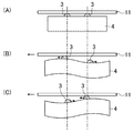
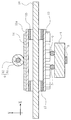
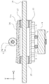
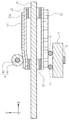
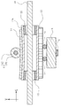
次に、アクチュエータ本体4とローラ6とで移動体11を押圧することにより移動体11に生じる変形について説明する。図10〜14に、移動体11を含む駆動装置の主要部材の断面図を示す。図10は、ローラ6が移動体11の中間部に位置し且つローラ6に付勢力が加わっていない状態を示す図であり、図11は、ローラ6が移動体11の中間部に位置し且つローラ6に付勢力が加わっている状態を示す図であり、図12は、第2摺動板14の弾性係数がローラ6と同じ構成において、ローラ6が移動体11の端部に位置し且つローラ6に付勢力が加わっている状態を示す図であり、図13は、第2摺動板14の弾性係数がローラ6よりも小さい構成において、ローラ6が移動体11の端部に位置し且つローラ6に付勢力が加わっている状態を示す図であり、図14は、ローラ6の弾性係数が第2摺動板14よりも小さい構成において、ローラ6が移動体11の中央に位置し且つローラ6に付勢力が加わっている状態を示す図である。ここで、特に言及しない限り、移動体11の中間部及び端部は、移動方向における移動体11の中間部及び端部を意味する。また、中間部とは、厳密な中央を意味するわけではなく、端部以外の部分を意味する。尚、移動体11の中央は、移動体11の移動ストロークの中央に相当する。   Next, deformation that occurs in the moving body 11 when the moving body 11 is pressed by the actuator body 4 and the roller 6 will be described. 10 to 14 are sectional views of main members of the drive device including the moving body 11. FIG. 10 is a view showing a state where the roller 6 is positioned at the intermediate portion of the moving body 11 and no urging force is applied to the roller 6, and FIG. 11 shows that the roller 6 is positioned at the intermediate portion of the moving body 11 and FIG. 12 is a diagram showing a state in which an urging force is applied to the roller 6, and FIG. 12 illustrates a configuration in which the elastic coefficient of the second sliding plate 14 is the same as that of the roller 6, and the roller 6 is positioned at the end of the movable body 11. FIG. 13 is a diagram illustrating a state in which an urging force is applied to the roller 6. FIG. 13 is a diagram illustrating a configuration in which the elastic coefficient of the second sliding plate 14 is smaller than that of the roller 6, and the roller 6 is positioned at the end of the moving body 11. FIG. 14 is a diagram showing a state in which an urging force is applied to the roller 6. FIG. 14 illustrates a configuration in which the roller 6 is positioned at the center of the moving body 11 in a configuration in which the elastic coefficient of the roller 6 is smaller than that of the second sliding plate 14. And it is a figure which shows the state in which urging | biasing force is added to the roller . Here, unless otherwise specified, the intermediate portion and the end portion of the moving body 11 mean the intermediate portion and the end portion of the moving body 11 in the moving direction. Further, the intermediate portion does not mean the exact center, but means a portion other than the end portion. The center of the moving body 11 corresponds to the center of the moving stroke of the moving body 11.

移動体11をアクチュエータ本体4とローラ6とで押圧すると、図11に示すように、移動体11のうちローラ6と当接する部分(以下、当接部分ともいう)では変形が生じ、移動体11のうち駆動子3,3と当接する部分ではほとんど変形が生じない。詳しくは、移動体11のうち駆動子3,3と当接する部分には剛性の高い第1摺動板13が設けられているため、第1摺動板13及び移動体本体11aはほとんど変形していない。このため、アクチュエータ本体4と移動体11の当接状態は良好であり、駆動子3、3と第1摺動板13との間の摩擦力を十分に確保することができ、アクチュエータ本体4の駆動力を移動体11に効率良く伝えることができる。   When the moving body 11 is pressed by the actuator body 4 and the roller 6, as shown in FIG. 11, a portion of the moving body 11 that contacts the roller 6 (hereinafter also referred to as a contact portion) is deformed, and the moving body 11 Of these, almost no deformation occurs in the portion in contact with the driving elements 3 and 3. Specifically, the first sliding plate 13 and the movable body main body 11a are almost deformed because the first sliding plate 13 having high rigidity is provided in a portion of the movable body 11 that contacts the driving elements 3 and 3. Not. For this reason, the contact state between the actuator body 4 and the movable body 11 is good, and a sufficient frictional force between the driver elements 3 and 3 and the first sliding plate 13 can be secured. The driving force can be efficiently transmitted to the moving body 11.

それに対して、移動体11のうちローラ6が当接する部分に設けられた第2摺動板14は、剛性が低いため、さらに詳しくは、ローラ6よりも剛性が低いため、変形する。その結果、移動体本体11aも変形する。ただし、このときの変形は、移動方向(図中のX方向)において、ローラ6の当接部分に対して対称である。つまり、第2摺動板14のうちローラ6が当接する部分は、実質的にX方向に平行になっているとみなせる。そのため、ローラ6からの押圧力は、第2摺動板14に対して、押圧力そのものの方向(Y方向)、即ち、連結部材7による付勢力の付勢方向に作用する。該押圧力からは、移動方向への成分は生じない。このとき、第2摺動板14が変形する一方で、ローラ本体61は殆ど変形していないため、ローラ6の回転を阻害する力は生じない。その結果、ローラ本体61は、スムーズに回転することができ、駆動装置1は、所望の性能を発揮できる。   On the other hand, the second sliding plate 14 provided in the portion of the moving body 11 where the roller 6 abuts has a low rigidity, and more specifically, since the rigidity is lower than that of the roller 6, the second sliding plate 14 is deformed. As a result, the movable body 11a is also deformed. However, the deformation at this time is symmetric with respect to the contact portion of the roller 6 in the moving direction (X direction in the figure). That is, it can be considered that the portion of the second sliding plate 14 with which the roller 6 abuts is substantially parallel to the X direction. Therefore, the pressing force from the roller 6 acts on the second sliding plate 14 in the direction of the pressing force itself (Y direction), that is, the urging direction of the urging force by the connecting member 7. No component in the moving direction is generated from the pressing force. At this time, while the second sliding plate 14 is deformed, the roller main body 61 is hardly deformed, so that a force that inhibits the rotation of the roller 6 does not occur. As a result, the roller body 61 can rotate smoothly, and the drive device 1 can exhibit desired performance.

次に、駆動子3,3及びローラ6が移動体11の端部と当接している場合の、移動体11の変形について説明する。   Next, the deformation of the moving body 11 when the driving elements 3 and 3 and the roller 6 are in contact with the end of the moving body 11 will be described.

まず、第2摺動板14の弾性係数がローラ6の弾性係数と同じ場合について説明する。例えば、第2摺動板14がステンレス合金で形成されている場合である。図12に示すように、駆動子3,3からの押圧力は、2つの駆動子3,3に分散されて第1摺動板13へ作用するため、第1摺動板13及び移動体本体11aの変形は小さい。それに対して、ローラ6は1つであるため、ローラ6からの押圧力は、第2摺動板14のうちローラ6が当接している部分に集中的に作用する。その結果、第2摺動板14は、当接部分が凹むように変形する。第2摺動板14の弾性係数はローラ6の弾性係数と同じであり且つ第2摺動板14の弾性係数は移動体本体11aの弾性係数よりも大きいため、第2摺動板14は、厚みが薄くなるように変形するのではなく、全体として湾曲するように変形する。その結果、第2摺動板14及び移動体本体11aが全体的に湾曲するように変形する。ここで、当接部分よりも中央側であって、当接部分よりも少し離れた部分は、殆ど変形していない。当接部分から該殆ど変形していない部分までは連続的に繋がっているため、当接部分から離れるにつれて、凹み量は減少していく。その結果、第2摺動板14は、該殆ど変形していない部分から当接部分に向かって凹み量が徐々に大きくなるように傾斜している。一方、当接部分よりも端縁側には、移動体11が少ししか存在しない。つまり、当接部分よりも端縁側においては、移動体11の変形を拘束する部分が少ない。そのため、当接部分から離れるにつれて凹み量は減少して元の状態に戻っていくものの、その戻り量は、当接部分よりも中央側の部分と比べて小さい。つまり、当接部分からの距離が同じであっても、中央側に比べて端縁側の方が変形量が大きい。これにより、第2摺動板14は、当接部分よりも中央側の部分は傾斜が比較的きつく、当接部分よりも端縁側の部分は傾斜が比較的緩くなっている。つまり、第2摺動板14のうちローラ6が当接する部分は、移動方向に平行ではなく、中央側よりも端縁側の方が沈み込むように傾斜している。   First, the case where the elastic coefficient of the second sliding plate 14 is the same as the elastic coefficient of the roller 6 will be described. For example, this is a case where the second sliding plate 14 is formed of a stainless alloy. As shown in FIG. 12, since the pressing force from the driver elements 3 and 3 is distributed to the two driver elements 3 and 3 and acts on the first sliding plate 13, the first sliding plate 13 and the movable body main body The deformation of 11a is small. On the other hand, since there is one roller 6, the pressing force from the roller 6 acts intensively on the portion of the second sliding plate 14 where the roller 6 is in contact. As a result, the second sliding plate 14 is deformed so that the contact portion is recessed. Since the elastic coefficient of the second sliding plate 14 is the same as the elastic coefficient of the roller 6 and the elastic coefficient of the second sliding plate 14 is larger than the elastic coefficient of the movable body 11a, the second sliding plate 14 is It does not deform so as to be thin, but deforms so as to be curved as a whole. As a result, the second sliding plate 14 and the movable body main body 11a are deformed so as to be entirely curved. Here, the portion closer to the center than the contact portion and slightly away from the contact portion is hardly deformed. Since the portion from the contact portion to the portion that is hardly deformed is continuously connected, the amount of the dent decreases as the distance from the contact portion increases. As a result, the second sliding plate 14 is inclined so that the dent amount gradually increases from the hardly deformed portion toward the contact portion. On the other hand, there is only a small amount of the moving body 11 on the edge side of the contact portion. That is, there are few parts which restrain the deformation | transformation of the mobile body 11 in the edge side rather than a contact part. For this reason, the dent amount decreases and returns to the original state as the distance from the contact portion increases, but the return amount is smaller than the central portion of the contact portion. That is, even when the distance from the contact portion is the same, the amount of deformation is larger on the edge side than on the center side. As a result, the second sliding plate 14 is relatively tightly inclined at the center side with respect to the abutting portion and relatively inclined at the end edge side of the abutting portion. That is, the portion of the second sliding plate 14 with which the roller 6 abuts is not parallel to the moving direction and is inclined so that the edge side sinks more than the center side.

その結果、ローラ6の押圧力からは、移動体11をX方向へ移動させる方向への成分が生じる。詳しくは、移動体11には、X方向において、移動体11がアクチュエータ本体4とローラ6による挟み込みから抜け出ようとする方向の力、即ち、抜出力が作用する。この抜出力は、移動体11の移動方向には無関係に、常に、移動体11に対して移動方向における端部から内側へ向かって作用する。   As a result, a component in the direction of moving the moving body 11 in the X direction is generated from the pressing force of the roller 6. Specifically, a force in a direction in which the moving body 11 tries to escape from the sandwiching between the actuator body 4 and the roller 6 in the X direction, that is, a pulling output acts on the moving body 11. Regardless of the moving direction of the moving body 11, this extraction output always acts on the moving body 11 from the end in the moving direction to the inside.

特に、第2摺動板14の弾性係数が大きい場合には、当接部分よりも端縁側の部分は、当接部分の変形につられて変形しやすく、当接部分における傾斜がきつくなる虞がある。このことは、抜出力が大きくなることを意味する。   In particular, when the elastic coefficient of the second sliding plate 14 is large, the portion on the edge side with respect to the abutting portion is easily deformed due to the deformation of the abutting portion, and the inclination at the abutting portion may be tight. is there. This means that the output is increased.

続いて、第2摺動板14の弾性係数がローラ6の弾性係数よりも小さい場合について説明する。例えば、第2摺動板14をプラスチック材料で形成し、ローラ本体61をステンレス合金で形成した場合である。図13に示すように、移動体11の変形を巨視的に見ると、当接部分よりも中央側ほど変形量が大きく、当接部分よりも端縁側ほど変形量が小さくなっている。しかし、第2摺動板14の弾性係数がローラ6の弾性係数よりも小さいので、第2摺動板14の厚みは変化し易くなっている。このため、第2摺動板14は、図12の例に比べて、当接部分が局所的に薄くなるように変形している。これにより、第2摺動板14のうちローラ6が当接する部分は、図12の例に比べて傾斜が緩く、又は、移動方向と実質的に平行となる。その結果、抜出力が低減される。このとき、第2摺動板14が変形する一方で、ローラ本体61は殆ど変形していないため、ローラ6の回転を阻害する力は生じない。その結果、ローラ本体61は、スムーズに回転することができ、駆動装置1は、所望の性能を発揮できる。   Subsequently, a case where the elastic coefficient of the second sliding plate 14 is smaller than the elastic coefficient of the roller 6 will be described. For example, the second sliding plate 14 is formed of a plastic material, and the roller body 61 is formed of a stainless alloy. As shown in FIG. 13, when the deformation of the moving body 11 is viewed macroscopically, the deformation amount is larger toward the center side than the contact portion, and the deformation amount is smaller toward the edge side than the contact portion. However, since the elastic coefficient of the second sliding plate 14 is smaller than that of the roller 6, the thickness of the second sliding plate 14 is easily changed. For this reason, the 2nd sliding plate 14 is deform | transforming so that a contact part may become thin locally compared with the example of FIG. As a result, the portion of the second sliding plate 14 with which the roller 6 abuts is less inclined than the example of FIG. 12, or is substantially parallel to the moving direction. As a result, the extraction output is reduced. At this time, while the second sliding plate 14 is deformed, the roller main body 61 is hardly deformed, so that a force that inhibits the rotation of the roller 6 does not occur. As a result, the roller body 61 can rotate smoothly, and the drive device 1 can exhibit desired performance.

したがって、本実施形態によれば、ローラ本体61と当接する第2摺動板14をローラ本体61よりも変形し易くすることによって、第2摺動板14の変形をローラ本体61を中心に移動方向において対称とすることができる。これにより、第2摺動板14におけるローラ本体61が当接する部分の傾きを低減することができ、移動体11に作用する抜出力を抑制することができる。そのため、移動体11の端部においても、移動体11の円滑な駆動を維持することができる。その結果、移動体11が正常に動作可能な移動ストロークを広げることができる。   Therefore, according to the present embodiment, the deformation of the second sliding plate 14 is moved around the roller body 61 by making the second sliding plate 14 in contact with the roller body 61 easier to deform than the roller body 61. It can be symmetric in the direction. Thereby, the inclination of the part which the roller main body 61 contact | abuts in the 2nd sliding plate 14 can be reduced, and the extraction output which acts on the mobile body 11 can be suppressed. Therefore, smooth driving of the moving body 11 can be maintained also at the end of the moving body 11. As a result, the moving stroke in which the moving body 11 can operate normally can be expanded.

また、ローラ本体61の弾性係数を第2摺動板14の弾性係数よりも大きくしているため、ローラ本体61自体の変形を抑制することができる。これにより、ローラ本体61のスムーズな回転を維持することができる。仮に、図14に示すように、ローラ本体61の弾性係数を第2摺動板14の弾性係数よりも小さくすると、ローラ本体61は、第2摺動板14と当接する部分が扁平に変形してしまう。このようにローラ本体61が変形すると、ローラ本体61の回転に対する抵抗力が生じることになるので、ローラ本体61のスムーズな回転を阻害してしまう。それに対して、本実施形態では、第2摺動板14が変形して、ローラ本体61は殆ど変形しないので、ローラ本体61をスムーズに回転させることができる。   Further, since the elastic coefficient of the roller main body 61 is larger than that of the second sliding plate 14, deformation of the roller main body 61 itself can be suppressed. Thereby, the smooth rotation of the roller body 61 can be maintained. As shown in FIG. 14, when the elastic coefficient of the roller body 61 is made smaller than the elastic coefficient of the second sliding plate 14, the roller main body 61 is deformed flatly at the portion in contact with the second sliding plate 14. End up. When the roller main body 61 is deformed in this manner, a resistance force against the rotation of the roller main body 61 is generated, so that the smooth rotation of the roller main body 61 is hindered. On the other hand, in this embodiment, since the 2nd sliding plate 14 deform | transforms and the roller main body 61 hardly deform | transforms, the roller main body 61 can be rotated smoothly.

《その他の実施形態》
実施形態について、以下のような構成としてもよい。
<< Other Embodiments >>
About embodiment, it is good also as the following structures.

例えば、移動体本体11aの形状は、前記実施形態に限られるものではなく、任意の形状を採用することができる。   For example, the shape of the mobile body 11a is not limited to the above embodiment, and any shape can be adopted.

さらに、軸受部15は、移動体本体11aの貫通孔11bの端部だけでなく、貫通孔11b全体に設けられていてもよい。   Furthermore, the bearing portion 15 may be provided not only at the end portion of the through hole 11b of the movable body main body 11a but also throughout the through hole 11b.

また、第1及び第2摺動板13,14は、何れか一方を省略してもよいし、両方を省略してもよい。ただし、第2摺動板14を省略する場合には、移動体11のうち、ローラ6と当接する部分は、該ローラ6よりも弾性係数が小さい材料で構成される。   Further, one of the first and second sliding plates 13 and 14 may be omitted, or both may be omitted. However, when the second sliding plate 14 is omitted, the portion of the moving body 11 that contacts the roller 6 is made of a material having a smaller elastic coefficient than that of the roller 6.

さらにまた、移動体本体11aや軸受部15の材料は、前記実施形態に限られるものではない。ただし、軸受部15の弾性係数が移動体本体11aの弾性係数よりも大きいことが好ましい。また、第1及び第2摺動板13,14の材料も、前記実施形態に限られるものではない。第1摺動板13の材料としては、任意の材料を採用することができ、移動体本体11aよりも弾性係数が大きい材料であれば好ましい。第2摺動板14の材料としても、任意の材料を採用することができ、ローラ6、詳しくはローラ本体61よりも弾性係数が小さい材料であれば良く、さらに移動体本体11aよりも弾性係数が小さい材料であれば好ましい。   Furthermore, the material of the mobile body 11a and the bearing portion 15 is not limited to the above embodiment. However, it is preferable that the elastic coefficient of the bearing portion 15 is larger than the elastic coefficient of the movable body 11a. Further, the material of the first and second sliding plates 13 and 14 is not limited to the above embodiment. Any material can be adopted as the material of the first sliding plate 13, and a material having an elastic coefficient larger than that of the movable body 11a is preferable. Any material can be adopted as the material of the second sliding plate 14, and any material having an elastic coefficient smaller than that of the roller 6, more specifically, the roller main body 61 may be used, and further, the elastic coefficient of the moving body main body 11a. Is preferably a small material.

前記実施形態では、対向部材としてローラ6が設けられているが、対向部材はローラ6に限られるものではない。例えば、対向部材は、ローラシャフトに対してローラ本体が回転不能に取り付けられたローラであってもよい。また、対向部材は、移動体11と単に当接するだけの当接部材であってもよい。この場合、当接部材は、連結部材7と別体に設けられてもよいし、一体に設けられてもよい。尚、当接部材は、移動体11との間の摩擦抵抗が小さいことが好ましい。さらに、対向部材は、別のアクチュエータ本体であってもよい。この場合、2つのアクチュエータ本体で移動体11を挟持することになる。つまり、移動体11は、2つのアクチュエータ本体で駆動される。すなわち、対向部材は、移動体11に当接すると共に該移動体11を挟んでアクチュエータ本体4と対向する位置に位置する部材であれば、任意の部材を採用することができる。   In the embodiment, the roller 6 is provided as the facing member, but the facing member is not limited to the roller 6. For example, the opposing member may be a roller in which the roller body is attached to the roller shaft so as not to rotate. Further, the facing member may be a contact member that simply contacts the moving body 11. In this case, the contact member may be provided separately from the connecting member 7 or may be provided integrally. The contact member preferably has a small frictional resistance with the moving body 11. Furthermore, the opposing member may be another actuator body. In this case, the moving body 11 is sandwiched between the two actuator bodies. That is, the moving body 11 is driven by two actuator bodies. In other words, any member can be used as long as the facing member is a member that is in contact with the moving body 11 and is located at a position facing the actuator body 4 with the moving body 11 interposed therebetween.

前記実施形態では、第2摺動板14の弾性係数をローラ6の弾性係数よりも小さくしているが、第1摺動板13とアクチュエータ本体4との関係においても同様の構成を採用してもよい。すなわち、第1摺動板13(即ち、アクチュエータ本体が当接する部分)の弾性係数を駆動子3,3の弾性係数よりも小さくしてもよい。   In the above embodiment, the elastic coefficient of the second sliding plate 14 is smaller than the elastic coefficient of the roller 6, but the same configuration is adopted for the relationship between the first sliding plate 13 and the actuator body 4. Also good. That is, the elastic coefficient of the first sliding plate 13 (that is, the portion with which the actuator main body abuts) may be smaller than the elastic coefficient of the driver elements 3 and 3.

また、アクチュエータ本体4と対向部材(本実施形態ではローラ6)との連結構造は、連結部材7による構成に限られるものではない。すなわち、アクチュエータ本体4と対向部材とを連結すると共にアクチュエータ本体4と対向部材とを移動体11を挟み込むように付勢する構成であれば、任意の構成を採用することができる。   Further, the connection structure between the actuator body 4 and the opposing member (the roller 6 in the present embodiment) is not limited to the configuration of the connection member 7. That is, any configuration can be adopted as long as the actuator main body 4 and the counter member are connected to each other and the actuator main body 4 and the counter member are biased so as to sandwich the moving body 11 therebetween.

さらに、連結部材7を省略することもできる。アクチュエータ本体4とローラ6とをそれぞれ移動体11に付勢して当接させる構成であれば、任意の構成を採用することができる。   Further, the connecting member 7 can be omitted. Any configuration can be adopted as long as the actuator body 4 and the roller 6 are configured to urge and contact the movable body 11 respectively.

また、支持体8による超音波アクチュエータ2の支持構造は、前記の構成に限られるものではない。例えば、ホルダ5は、第1及び第2支持板81,82のガイド部材88に支持されているが、ガイド部材88は必ずしも必要ではない。すなわち、第1及び第2支持板81,82に形成された開口部84a,82aを介して直接、支持してもよい。また、連結部材7に設けた突出部を、支持体8のガイド孔88aやガイド溝85a,86aで支持する構成であってもよい。また、連結部材7やアクチュエータ本体4に前記付勢方向に延びるガイド孔又はガイド溝を形成する一方、支持体8に該ガイド孔又はガイド溝に係合する係合部を設ける構成であってもよい。すなわち、超音波アクチュエータ2を前記付勢方向に変位可能に支持できる構成であれば、任意の構成を採用することができる。   Further, the support structure of the ultrasonic actuator 2 by the support 8 is not limited to the above-described configuration. For example, the holder 5 is supported by the guide members 88 of the first and second support plates 81 and 82, but the guide member 88 is not always necessary. That is, you may support directly through opening part 84a, 82a formed in the 1st and 2nd support plates 81,82. Moreover, the structure which supports the protrusion part provided in the connection member 7 with the guide hole 88a of the support body 8, or guide groove 85a, 86a may be sufficient. Further, a guide hole or a guide groove extending in the biasing direction may be formed in the connecting member 7 or the actuator body 4, while an engaging portion that engages with the guide hole or the guide groove may be provided in the support body 8. Good. In other words, any configuration can be adopted as long as the configuration can support the ultrasonic actuator 2 so as to be displaceable in the biasing direction.

前記実施形態では、超音波アクチュエータ2が、柱状の移動体11を駆動する構成について説明しているが、本実施形態は様々な対象物を駆動する構成に採用することができる。例えば、超音波アクチュエータ2によりカメラのレンズ枠を駆動するように構成してもよい。かかる場合、レンズ枠と一体的に移動体11が設けられ、該レンズ枠がシャフト10に沿って移動可能なように構成される。このようなレンズ枠を超音波アクチュエータ2により駆動する構成であってもよい。   In the above-described embodiment, the configuration in which the ultrasonic actuator 2 drives the columnar moving body 11 has been described. However, the present embodiment can be employed in a configuration that drives various objects. For example, the lens frame of the camera may be driven by the ultrasonic actuator 2. In such a case, the movable body 11 is provided integrally with the lens frame, and the lens frame is configured to be movable along the shaft 10. Such a lens frame may be driven by the ultrasonic actuator 2.

さらに、前記実施形態では、アクチュエータ本体4が固定され、移動体11が移動しているが、これに限られるものではない。アクチュエータ本体4と移動体11とが相対的に移動する構成であればよい。例えば、移動体11が固定され、アクチュエータ本体4が移動する構成であってもよい。   Furthermore, in the said embodiment, although the actuator main body 4 is fixed and the mobile body 11 is moving, it is not restricted to this. What is necessary is just the structure which the actuator main body 4 and the mobile body 11 move relatively. For example, the moving body 11 may be fixed and the actuator body 4 may move.

また、超音波アクチュエータ2は、アクチュエータ本体4に1次モードの伸縮振動と2次モードの屈曲振動とを発生させているが、これに限られるものではない。アクチュエータ本体4に伸縮振動と屈曲振動とを発生させる構成であれば、任意の次数の振動を発生させるアクチュエータ本体を採用することができる。   In addition, the ultrasonic actuator 2 causes the actuator body 4 to generate the first-order mode stretching vibration and the second-order bending vibration, but is not limited thereto. If the actuator body 4 is configured to generate stretching vibration and bending vibration, an actuator body that generates vibrations of any order can be employed.

さらに、アクチュエータ本体4は、長辺側面40cに駆動子3,3が2つ設けられているが、これに限られるものではない。例えば、駆動子をアクチュエータ本体4の短辺側面40eに設ける構成であってもよい。この場合、アクチュエータ本体4の短辺側面40eが移動体11に対向するようにして、アクチュエータ本体4が移動体11に当接する。そして、アクチュエータ本体4からは、その屈曲振動の方向へ駆動力が出力される。   Furthermore, although the actuator body 4 is provided with two driver elements 3 and 3 on the long side surface 40c, it is not limited to this. For example, the structure which provides a drive element in the short side surface 40e of the actuator main body 4 may be sufficient. In this case, the actuator body 4 contacts the moving body 11 such that the short side surface 40 e of the actuator body 4 faces the moving body 11. A driving force is output from the actuator body 4 in the direction of the bending vibration.

尚、以上の実施形態は、本質的に好ましい例示であって、本発明、その適用物、あるいはその用途の範囲を制限することを意図するものではない。   In addition, the above embodiment is an essentially preferable illustration, Comprising: It does not intend restrict | limiting the range of this invention, its application thing, or its use.

以上説明したように、ここに開示された技術は、移動体を振動型アクチュエータで駆動する駆動装置について有用である。   As described above, the technology disclosed herein is useful for a drive device that drives a moving body with a vibration actuator.

1 駆動装置
2 超音波アクチュエータ(振動型アクチュエータ)
4 アクチュエータ本体
6 ローラ(対向部材)
7 連結部材
8 支持体(支持部)
10 シャフト
11 移動体
11a 移動体本体
13 第1摺動板(摺動部材)
1 Drive 2 Ultrasonic actuator (vibration type actuator)
4 Actuator body 6 Roller (opposing member)
7 Connecting member 8 Support body (support part)
10 Shaft 11 Moving object 11a Moving object body 13 First sliding plate (sliding member)

Claims (5)

振動することによって駆動力を出力するアクチュエータ本体と、
前記アクチュエータ本体が当接しており、該アクチュエータ本体に対して所定の移動方向に相対的に移動可能な移動体と、
前記移動体を挟んで前記アクチュエータ本体と対向する位置に配置され、該アクチュエータ本体と共に該移動体を挟持する対向部材とを備え、
前記移動体のうち、前記対向部材と当接する部分は、該対向部材よりも弾性係数が小さい駆動装置。
An actuator body that outputs a driving force by vibrating;
A movable body that is in contact with the actuator body and is movable relative to the actuator body in a predetermined movement direction;
An opposing member that is disposed at a position facing the actuator body across the moving body, and sandwiches the moving body together with the actuator body,
The drive unit in which the elastic member has a smaller elastic coefficient in a portion of the moving body that comes into contact with the opposing member.
前記アクチュエータ本体と前記対向部材とを連結し、該アクチュエータ本体及び対向部材が前記移動体を押圧するように該アクチュエータ本体及び対向部材を付勢する連結部材をさらに備える、請求項1に記載の駆動装置。   2. The drive according to claim 1, further comprising a connecting member that connects the actuator body and the facing member, and that biases the actuator body and the facing member so that the actuator body and the facing member press the moving body. apparatus. 前記移動体を前記移動方向に移動可能に支持するシャフトをさらに備える、請求項1又は2に記載の駆動装置。   The drive device according to claim 1, further comprising a shaft that supports the movable body so as to be movable in the movement direction. 前記アクチュエータ本体を、前記連結部材により付勢する方向に沿って変位可能に支持する支持部をさらに備える、請求項2に記載の駆動装置。   The drive device according to claim 2, further comprising a support portion that supports the actuator body so as to be displaceable along a direction in which the actuator body is urged by the connecting member. 前記移動体は、移動体本体と、該移動体本体に設けられ、前記アクチュエータ本体と当接する摺動部材とを有し、
前記摺動部材は、前記移動体本体よりも弾性係数が大きい、請求項1乃至4の何れか1つに記載の駆動装置。
The moving body has a moving body main body, and a sliding member provided on the moving body main body and in contact with the actuator main body,
The drive device according to claim 1, wherein the sliding member has a larger elastic coefficient than the movable body main body.
JP2011136051A 2010-08-04 2011-06-20 Drive device Expired - Fee Related JP5909624B2 (en)

Priority Applications (1)

Application Number Priority Date Filing Date Title
JP2011136051A JP5909624B2 (en) 2010-08-04 2011-06-20 Drive device

Applications Claiming Priority (3)

Application Number Priority Date Filing Date Title
JP2010175021 2010-08-04
JP2011136051A JP5909624B2 (en) 2010-08-04 2011-06-20 Drive device

Publications (2)

Publication Number Publication Date
JP2012055152A true JP2012055152A (en) 2012-03-15
JP5909624B2 JP5909624B2 (en) 2016-04-27

Family

ID=45555085

Family Applications (1)

Application Number Title Priority Date Filing Date
JP2011136051A Expired - Fee Related JP5909624B2 (en) 2010-08-04 2011-06-20 Drive device

Country Status (2)

Country Link
US (1) US8729773B2 (en)
JP (1) JP5909624B2 (en)

Cited By (3)

* Cited by examiner, † Cited by third party
Publication number Priority date Publication date Assignee Title
JP2014093871A (en) * 2012-11-04 2014-05-19 Canon Inc Ultrasonic motor and apparatus driving device with ultrasonic motor
JP2014093872A (en) * 2012-11-04 2014-05-19 Canon Inc Ultrasonic motor and apparatus driving device with ultrasonic motor
JP2020205735A (en) * 2019-06-19 2020-12-24 キヤノン株式会社 Vibration type actuator, device, multi-axial stage unit, and multi-joint robot

Families Citing this family (3)

* Cited by examiner, † Cited by third party
Publication number Priority date Publication date Assignee Title
TWI429977B (en) * 2011-03-07 2014-03-11 Quanta Comp Inc Adjustment mechanism
JP6271963B2 (en) * 2013-11-21 2018-01-31 キヤノン株式会社 Vibration type actuator
RU2624773C1 (en) * 2016-07-05 2017-07-06 Федеральное государственное бюджетное образовательное учреждение высшего образования "Пензенский государственный университет" (ФГБОУ ВО "Пензенский государственный университет") Amplifying piezoelectric actuator of increased positional accuracy

Citations (9)

* Cited by examiner, † Cited by third party
Publication number Priority date Publication date Assignee Title
JPH0294485U (en) * 1989-01-09 1990-07-26
JPH0393479A (en) * 1989-09-04 1991-04-18 Brother Ind Ltd Ultrasonic motor
JPH06319279A (en) * 1993-04-28 1994-11-15 Olympus Optical Co Ltd Ultrasonic linear actuator
JPH11136968A (en) * 1997-10-29 1999-05-21 Kyocera Corp Ultrasonic drive device
US6069420A (en) * 1996-10-23 2000-05-30 Omnific International, Ltd. Specialized actuators driven by oscillatory transducers
JP2007120613A (en) * 2005-10-27 2007-05-17 Nsk Ltd Rolling sliding member and rolling device
JP2008172995A (en) * 2006-12-15 2008-07-24 Olympus Imaging Corp Drive unit and imaging device
JP2008246637A (en) * 2007-03-30 2008-10-16 Tohoku Univ Manufacturing method of metal glass sphere, bearing using metal glass sphere manufactured by the method, ball point pen with metal glass sphere attached on pen point, and ornament using metal glass sphere
JP2010161857A (en) * 2009-01-07 2010-07-22 Panasonic Corp Drive system

Family Cites Families (13)

* Cited by examiner, † Cited by third party
Publication number Priority date Publication date Assignee Title
JP3184117B2 (en) 1997-05-23 2001-07-09 セイコーインスツルメンツ株式会社 Ultrasonic motor and electronic device with ultrasonic motor
US6430873B1 (en) * 2000-03-08 2002-08-13 Atoma International Corporation Dual drum and rail window regulator drive system
JP2004166479A (en) * 2002-06-14 2004-06-10 Seiko Epson Corp Rotary drive device and apparatus equipped with same
US7242131B2 (en) * 2004-05-12 2007-07-10 Olympus Corporation Ultrasonic motor
JP4689989B2 (en) * 2004-08-27 2011-06-01 オリンパス株式会社 Vibration wave linear motor and lens device using the same
KR100880379B1 (en) * 2006-05-25 2009-01-23 삼성전자주식회사 Information Processing System being boosted by boot code from external
US7893598B2 (en) 2006-12-15 2011-02-22 Olympus Imaging Corp. Driving apparatus and image pickup apparatus
US8297149B2 (en) * 2007-02-28 2012-10-30 Konica Minolta Opto, Inc. Friction drive actuator
JP2008245507A (en) 2007-02-28 2008-10-09 Konica Minolta Opto Inc Friction drive actuator
WO2008152821A1 (en) * 2007-06-14 2008-12-18 Panasonic Corporation Oscillation type actuator and drive device using the same
JP5244727B2 (en) * 2009-07-27 2013-07-24 パナソニック株式会社 Vibration type actuator
JP5979817B2 (en) * 2010-03-16 2016-08-31 キヤノン株式会社 Vibration wave drive
JP5810303B2 (en) * 2010-04-06 2015-11-11 パナソニックIpマネジメント株式会社 Drive device

Patent Citations (9)

* Cited by examiner, † Cited by third party
Publication number Priority date Publication date Assignee Title
JPH0294485U (en) * 1989-01-09 1990-07-26
JPH0393479A (en) * 1989-09-04 1991-04-18 Brother Ind Ltd Ultrasonic motor
JPH06319279A (en) * 1993-04-28 1994-11-15 Olympus Optical Co Ltd Ultrasonic linear actuator
US6069420A (en) * 1996-10-23 2000-05-30 Omnific International, Ltd. Specialized actuators driven by oscillatory transducers
JPH11136968A (en) * 1997-10-29 1999-05-21 Kyocera Corp Ultrasonic drive device
JP2007120613A (en) * 2005-10-27 2007-05-17 Nsk Ltd Rolling sliding member and rolling device
JP2008172995A (en) * 2006-12-15 2008-07-24 Olympus Imaging Corp Drive unit and imaging device
JP2008246637A (en) * 2007-03-30 2008-10-16 Tohoku Univ Manufacturing method of metal glass sphere, bearing using metal glass sphere manufactured by the method, ball point pen with metal glass sphere attached on pen point, and ornament using metal glass sphere
JP2010161857A (en) * 2009-01-07 2010-07-22 Panasonic Corp Drive system

Cited By (4)

* Cited by examiner, † Cited by third party
Publication number Priority date Publication date Assignee Title
JP2014093871A (en) * 2012-11-04 2014-05-19 Canon Inc Ultrasonic motor and apparatus driving device with ultrasonic motor
JP2014093872A (en) * 2012-11-04 2014-05-19 Canon Inc Ultrasonic motor and apparatus driving device with ultrasonic motor
JP2020205735A (en) * 2019-06-19 2020-12-24 キヤノン株式会社 Vibration type actuator, device, multi-axial stage unit, and multi-joint robot
JP7353815B2 (en) 2019-06-19 2023-10-02 キヤノン株式会社 Vibratory actuators, devices, multi-axis stage units, and articulated robots

Also Published As

Publication number Publication date
US8729773B2 (en) 2014-05-20
JP5909624B2 (en) 2016-04-27
US20120031209A1 (en) 2012-02-09

Similar Documents

Publication Publication Date Title
JP5810303B2 (en) Drive device
KR101685362B1 (en) Vibration actuator and lens apparatus including the same
US10171008B2 (en) Vibration wave motor and driving apparatus using the vibration wave motor
JP5909624B2 (en) Drive device
JP5244727B2 (en) Vibration type actuator
JP2008178250A (en) Pressing mechanism of ultrasonic resonator and ultrasonic motor
JP2014018027A (en) Vibration type actuator, imaging apparatus, and stage
JP6049277B2 (en) Vibration type driving device
US10120158B2 (en) Vibration-type actuator and optical device using the same
JP6257224B2 (en) Motor and lens device
JP2007325466A (en) Driving apparatus
JP5202538B2 (en) Vibration type actuator
US9455394B2 (en) Displacement member, driving member, actuator, and driving device
US10924037B2 (en) Vibration motor that prevents resonance of contact member, and electronic apparatus
JP2013156295A (en) Lens drive device
US7687974B2 (en) Vibration type driving apparatus
US20110095650A1 (en) Ultrasonic motor
JP6708472B2 (en) Vibration wave motor and optical device equipped with the vibration wave motor
JP2010161857A (en) Drive system
JP6479238B2 (en) motor
US20080258578A1 (en) Driving device capable of obtaining a stable frequency characteristic
JP7130727B2 (en) Vibration wave motor and device using the same
JP7098438B2 (en) Vibration wave motor and drive device using vibration wave motor
JP7406888B2 (en) Vibration type motor and drive device
JP7034770B2 (en) Vibration wave motor and lens device

Legal Events

Date Code Title Description
A621 Written request for application examination

Free format text: JAPANESE INTERMEDIATE CODE: A621

Effective date: 20140131

RD02 Notification of acceptance of power of attorney

Free format text: JAPANESE INTERMEDIATE CODE: A7422

Effective date: 20140131

A131 Notification of reasons for refusal

Free format text: JAPANESE INTERMEDIATE CODE: A131

Effective date: 20140909

A977 Report on retrieval

Free format text: JAPANESE INTERMEDIATE CODE: A971007

Effective date: 20140910

A711 Notification of change in applicant

Free format text: JAPANESE INTERMEDIATE CODE: A711

Effective date: 20141008

A521 Request for written amendment filed

Free format text: JAPANESE INTERMEDIATE CODE: A523

Effective date: 20141110

A131 Notification of reasons for refusal

Free format text: JAPANESE INTERMEDIATE CODE: A131

Effective date: 20150623

A521 Request for written amendment filed

Free format text: JAPANESE INTERMEDIATE CODE: A523

Effective date: 20150820

A131 Notification of reasons for refusal

Free format text: JAPANESE INTERMEDIATE CODE: A131

Effective date: 20150908

A521 Request for written amendment filed

Free format text: JAPANESE INTERMEDIATE CODE: A523

Effective date: 20151106

TRDD Decision of grant or rejection written
A01 Written decision to grant a patent or to grant a registration (utility model)

Free format text: JAPANESE INTERMEDIATE CODE: A01

Effective date: 20160105

A61 First payment of annual fees (during grant procedure)

Free format text: JAPANESE INTERMEDIATE CODE: A61

Effective date: 20160118

R151 Written notification of patent or utility model registration

Ref document number: 5909624

Country of ref document: JP

Free format text: JAPANESE INTERMEDIATE CODE: R151

LAPS Cancellation because of no payment of annual fees