JP6806472B2 - Vibration wave motor and optical equipment to which the vibration wave motor is applied - Google Patents
Vibration wave motor and optical equipment to which the vibration wave motor is applied Download PDFInfo
- Publication number
- JP6806472B2 JP6806472B2 JP2016120606A JP2016120606A JP6806472B2 JP 6806472 B2 JP6806472 B2 JP 6806472B2 JP 2016120606 A JP2016120606 A JP 2016120606A JP 2016120606 A JP2016120606 A JP 2016120606A JP 6806472 B2 JP6806472 B2 JP 6806472B2
- Authority
- JP
- Japan
- Prior art keywords
- vibration wave
- wave motor
- guide
- vibrator
- force
- Prior art date
- Legal status (The legal status is an assumption and is not a legal conclusion. Google has not performed a legal analysis and makes no representation as to the accuracy of the status listed.)
- Active
Links
- 230000003287 optical effect Effects 0.000 title claims description 14
- 238000005096 rolling process Methods 0.000 claims description 19
- ORQBXQOJMQIAOY-UHFFFAOYSA-N nobelium Chemical compound [No] ORQBXQOJMQIAOY-UHFFFAOYSA-N 0.000 description 6
- 238000000034 method Methods 0.000 description 2
- 239000000853 adhesive Substances 0.000 description 1
- 230000001070 adhesive effect Effects 0.000 description 1
- CNQCVBJFEGMYDW-UHFFFAOYSA-N lawrencium atom Chemical compound [Lr] CNQCVBJFEGMYDW-UHFFFAOYSA-N 0.000 description 1
- 230000013011 mating Effects 0.000 description 1
- 230000002093 peripheral effect Effects 0.000 description 1
Images


Classifications
-
- H—ELECTRICITY
- H02—GENERATION; CONVERSION OR DISTRIBUTION OF ELECTRIC POWER
- H02N—ELECTRIC MACHINES NOT OTHERWISE PROVIDED FOR
- H02N2/00—Electric machines in general using piezoelectric effect, electrostriction or magnetostriction
- H02N2/0005—Electric machines in general using piezoelectric effect, electrostriction or magnetostriction producing non-specific motion; Details common to machines covered by H02N2/02 - H02N2/16
- H02N2/005—Mechanical details, e.g. housings
- H02N2/0055—Supports for driving or driven bodies; Means for pressing driving body against driven body
- H02N2/006—Elastic elements, e.g. springs
-
- G—PHYSICS
- G02—OPTICS
- G02B—OPTICAL ELEMENTS, SYSTEMS OR APPARATUS
- G02B7/00—Mountings, adjusting means, or light-tight connections, for optical elements
- G02B7/02—Mountings, adjusting means, or light-tight connections, for optical elements for lenses
- G02B7/04—Mountings, adjusting means, or light-tight connections, for optical elements for lenses with mechanism for focusing or varying magnification
- G02B7/08—Mountings, adjusting means, or light-tight connections, for optical elements for lenses with mechanism for focusing or varying magnification adapted to co-operate with a remote control mechanism
-
- H—ELECTRICITY
- H02—GENERATION; CONVERSION OR DISTRIBUTION OF ELECTRIC POWER
- H02N—ELECTRIC MACHINES NOT OTHERWISE PROVIDED FOR
- H02N2/00—Electric machines in general using piezoelectric effect, electrostriction or magnetostriction
- H02N2/0005—Electric machines in general using piezoelectric effect, electrostriction or magnetostriction producing non-specific motion; Details common to machines covered by H02N2/02 - H02N2/16
- H02N2/001—Driving devices, e.g. vibrators
-
- H—ELECTRICITY
- H02—GENERATION; CONVERSION OR DISTRIBUTION OF ELECTRIC POWER
- H02N—ELECTRIC MACHINES NOT OTHERWISE PROVIDED FOR
- H02N2/00—Electric machines in general using piezoelectric effect, electrostriction or magnetostriction
- H02N2/02—Electric machines in general using piezoelectric effect, electrostriction or magnetostriction producing linear motion, e.g. actuators; Linear positioners ; Linear motors
- H02N2/026—Electric machines in general using piezoelectric effect, electrostriction or magnetostriction producing linear motion, e.g. actuators; Linear positioners ; Linear motors by pressing one or more vibrators against the driven body
Description
本発明は、振動波モータ及び振動波モータを適用した光学機器に関するものである。 The present invention relates to a vibration wave motor and an optical device to which the vibration wave motor is applied.
従来、超音波モータは、高周波電圧の印加により周期的に振動する振動子を摺動部材に圧接させることで、振動子と摺動部材とを相対的に移動させることができる構成を有する。特許文献1には、振動子がバネの加圧力により接触基礎部材に付勢されている構成のリニア超音波モータが開示されている。そして、加圧力に対する加圧反力は、振動子支持部材に取り付けられた移動板の可動案内部と、カバープレートのカバー案内部との間に転動部材を挟持することで受け止められている。
Conventionally, an ultrasonic motor has a configuration in which an oscillator and a sliding member can be relatively moved by pressure-contacting a sliding member with an oscillator that vibrates periodically by applying a high-frequency voltage.
しかしながら、従来のような構成においては、振動子の加圧反力の受け部としての転動部材を移動方向に沿って振動子の両側に二列設ける必要があるので、リニア超音波モータの小型化が難しいという問題がある。 However, in the conventional configuration, since it is necessary to provide two rows of rolling members on both sides of the vibrator along the moving direction as receiving parts of the pressurizing reaction force of the vibrator, the size of the linear ultrasonic motor is small. There is a problem that it is difficult to convert.
本発明にかかる振動波モータは、圧電素子を有する振動子と、加圧力を受けて該振動子が加圧接触する摩擦部材と、前記振動子を前記摩擦部材に対して相対移動の方向にガイドするガイド部材と、カバー部材と、を有する振動波モータにおいて、前記ガイド部材は、一端部に外部からの力を受入れる入力部と、前記一端部の反対側に位置する他端部に前記加圧力を前記振動子に付与する加圧部とを有し、前記入力部と前記加圧部との間には、前記相対移動の方向に沿って延在する第一のガイド部が形成されていて、前記カバー部材には、前記第一のガイド部に対向して位置する第二のガイド部が形成され、前記第一のガイド部及び前記第二のガイド部が協働することにより前記外部からの力に応じて前記加圧力が働くことを特徴とする。
The vibration wave motor according to the present invention guides a vibrator having a piezoelectric element, a friction member that the vibrator receives pressure and makes pressure contact, and the vibrator in a direction of relative movement with respect to the friction member. In a vibration wave motor having a guide member and a cover member, the guide member has an input portion that receives an external force at one end portion and a pressing force at the other end portion located on the opposite side of the one end portion. the have a pressing imparted to the vibrator, between the pressing and the input unit, the first guide portion be formed extending along the direction of the relative movement A second guide portion located opposite to the first guide portion is formed on the cover member, and the first guide portion and the second guide portion cooperate with each other to form the cover member from the outside. It is characterized in that the pressing force acts according to the force of .
本発明によれば、振動子の加圧反力の受け部としての転動部材を相対移動の方向に沿って、振動子の片側のみに配置することができるので振動波モータを小型化することができる。また、加圧ガイド部材が振動子の加圧と保持とを担っているので、部材を減らすことが可能となり、振動波モータを小型化することができる。 According to the present invention, the rolling member as a receiving portion of the pressurizing reaction force of the vibrator can be arranged on only one side of the vibrator along the direction of relative movement, so that the vibration wave motor can be miniaturized. Can be done. Further, since the pressurizing guide member is responsible for pressurizing and holding the vibrator, the number of members can be reduced and the vibration wave motor can be miniaturized.
以下に、本発明の好ましい実施形態の概要を添付の図面に基づいて説明する。図1は、本発明の実施形態を示す振動波モータ1(超音波モータ)の相対移動の方向A(図2参照)に直交する面における要部断面図、図2は図1の断面線II−IIにおける断面図であって、相対移動の方向Aにおける断面図である。図3は、加圧ガイド部材105に係合する部材の構成を示した分解斜視図である。また本実施形態は、直動型の振動波モータ1を例に説明するが、回転型やその他のタイプへの応用も可能である。
The outline of the preferred embodiment of the present invention will be described below with reference to the accompanying drawings. FIG. 1 is a cross-sectional view of a main part on a plane orthogonal to the direction A (see FIG. 2) of relative movement of the vibration wave motor 1 (ultrasonic motor) showing the embodiment of the present invention, and FIG. 2 is a cross-sectional line II of FIG. It is a cross-sectional view in −II, and is a cross-sectional view in the direction A of relative movement. FIG. 3 is an exploded perspective view showing the configuration of a member that engages with the
振動板101には、圧電素子102が公知の接着剤などにより固着されている。圧電素子102に高周波駆動電圧が印加されると、超音波領域の周波数の振動が発生し、振動板101が長手方向、短手方向のそれぞれに共振を起こすように設定されている。振動板101と圧電素子102とによって振動子100が構成されている。
The
圧電素子102に超音波領域の周波数の振動が発生すると、振動板101に形成された圧接部101aは図2に示すような楕円運動Mを起こす。圧電素子102に印加する高周波駆動電圧の周波数や位相を変えることで、楕円運動Mの回転方向や楕円比を適宜変化させて所望の動きを発生させることができる。そして、振動板101の圧接部101aを相手部品である摩擦部材103に加圧接触させることにより、振動子100と摩擦部材103とを相対的に移動させる駆動力を発生させることができる。そして、光軸方向(図1中紙面直交方向、図2中、左右方向)を相対移動の方向Aとして、振動子100を駆動することができる。摩擦部材103は、筐体104にネジ等、公知の締結手段によって固定される。
When vibration of a frequency in the ultrasonic region is generated in the
加圧ガイド部材105は、後述するように、一端部105−1に外部からの力(付勢力Fa)を受入れる入力部105a、その一端部105−1(図3参照)の反対側に位置する他端部105−2に加圧板106を加圧する加圧部105bが構成されている。また、加圧ガイド部材105は、加圧板106を加圧する加圧力Fbによって振動子100を保持する機能も有している。そして、入力部105aと加圧部105bとの間には、振動子100の相対移動の方向Aに沿って延在する複数の第一のガイド部105cが略一列に形成されている。
As will be described later, the pressurizing
カバー部材107は、筐体104に公知のネジなどにより固定されている。該カバー部材107には、二つの第一のガイド部105cの対向する位置に第二のガイド部107aが二つ形成されている。そして、これら第一のガイド部105cと対応する第二のガイド部107aとの間には、それぞれ転動部材108が組み込まれ、これらの転動部材108は後述の挟持力Fcにより挟持される。
The
レンズ保持部材112は、不図示の撮影レンズを保持しており、光軸方向(図1中紙面直交方向、図2中、左右方向)に沿って、ガイドバー110によって摺動自在に保持されている。ラック111は、レンズ保持部材112に対して中心軸B(図1中紙面直交方向、図2中、左右方向)を回転中心として回転可能に保持される。そして、ラック111には、トーションバネ113の回転付勢力により時計方向の回転力Frが付与される。この回転力Frは、係合球体114を介して加圧ガイド部材105の一端部105−1に設けられた入力部105aに外部からの力(付勢力Fa)として受入れられる。
The
以上説明した構成において、振動子100、摩擦部材103、筐体104、加圧ガイド部材105、加圧板106、カバー部材107、転動部材108により振動波モータ1が構成されている。
In the configuration described above, the
次に、本発明の実施形態における振動子100の加圧方法及び加圧ガイド部材105の相対移動におけるガイド機構について詳述する。上述の概要のとおり、レンズ保持部材112に取りつけられたラック111には、トーションバネ113により回転力Frが図1に示すように時計方向へ付与されている。この回転力Frは、組み込み状態において、係合球体114を介して加圧ガイド部材105の一端部105−1に設けられた入力部105aを図1の上方向に付勢する付勢力Faとして作用する。
Next, the method of pressurizing the
まず、振動子100の加圧方法について以下に説明する。付勢力Faが加圧ガイド部材105の一端部105−1に設けられた入力部105aへ作用すると、加圧ガイド部材105には、転動部材108の球芯を中心として反時計方向へ回転しようとする力が発生する。そして、この付勢力Faは、第一のガイド部105c、転動部材108及び固定端である第二のガイド部107aが協働することにより、一端部105−1の反対側に位置する他端部105−2に設けられた加圧部105bへ加圧力Fbとして働く。加圧力Fbは、加圧板106を介して振動子100を摩擦部材103に対して加圧し、振動子100と摩擦部材103とを摩擦接触させる。加圧力Fbの方向は、振動子100が摩擦部材103の摺動面に対して垂直となる方向に倣うことが好ましい。
First, a method of pressurizing the
振動子100が加圧力Fbにより加圧される際、第一のガイド部105cには、入力部105aの付勢力Fa及び加圧力Fbの加圧反力Fb’が働き、これらの力が転動部材108を介して第二のガイド部107aに伝わる。そして、第二のガイド部107aに伝わるこれらの力に対向する力が挟持力Fcとして転動部材108に働き、結果として転動部材108は、第一のガイド部105cと第二のガイド部107aとの間に挟持される。この挟持力Fcにより転動部材108は、第一のガイド部105c及び第二のガイド部107aの間で相対移動の方向Aに転動自在に、且つガタなく保持される。
When the
上述のように本発明の振動波モータ1の振動子100には、加圧ガイド部材105により加圧力Fbが与えられると同時に、加圧ガイド部材105により振動子100が保持される。従来のような構成では、振動子を支持する支持部材、振動子を加圧するバネ部材及びバネ部材を保持するバネ保持部材等が別部材として必要であったが、本発明の実施形態では、振動子100の加圧と保持を1つの部材である加圧ガイド部材105が担っている。このような構成とすることで、部材を減らすことが可能となり、装置の小型化が可能となる。
As described above, the
摩擦部材103は、筐体104に公知のネジなどにより固定され、第二のガイド部107aを有するカバー部材107も同じく公知のネジなどにより筐体104に固定されている。さらに、振動波モータ1は、レンズ保持部材112を保持する不図示の鏡筒にネジなど公知の手段により固定されている。
The
上述の構成において、圧電素子102に高周波駆動電圧を印加し、超音波領域の周波数の振動を発生させることで、振動板101に形成された圧接部101aに図2に示すような楕円運動Mを発生させる。そして、摩擦部材103と摩擦接触する振動子100は、相対移動の方向Aに沿って進退可能になり、加圧ガイド部材105及びラック111と連結されたレンズ保持部材112も振動子100と一体となって光軸方向に沿って進退可能になる。
In the above configuration, by applying a high-frequency drive voltage to the
次に加圧ガイド部材105の相対移動におけるガイド機構について以下に説明する。加圧ガイド部材105が有する第一のガイド部105cは、図1に示すように断面がV字形状であって、図3に示すように相対移動の方向Aに延在する溝となっており、ここに転動部材108が相対移動の方向Aに転動自在に組み込まれている。さらにカバー部材107にも第一のガイド部105cと同様、断面がV字形状であって相対移動の方向Aに延在する第二のガイド部107aが形成されており、第一のガイド部105cと同様、転動部材108が相対移動の方向Aに転動自在に組み込まれている。
Next, the guide mechanism in the relative movement of the
図3は、本発明の振動波モータ1の加圧ガイド部材105に係合する部材の構成を示した分解斜視図である。加圧ガイド部材105は、相対移動の方向Aに延在する延在部105−3に第一のガイド部105cを略一列に2か所備えている。そして、相対移動の方向Aに略直交する方向において、加圧ガイド部材105の延在部105−3から一端部105−1と他端部105−2のそれぞれが延出している。すなわち、振動子100を加圧して保持する部分である一端部105−1及び他端部105−2と、振動子100を相対移動の方向Aにガイドする部分である第一のガイド部105cを備えた延在部105−3とは、平面視において略十字形状の配置となっている。
FIG. 3 is an exploded perspective view showing the configuration of a member engaged with the pressurizing
これら二つの第一のガイド部105cは、入力部105aを有する一端部105−1と加圧部105bを有する他端部105−2とを挟む構成となっている。このような構成により、加圧ガイド部材105は、加圧保持している振動子100を光軸方向に沿って直線状に進退可能にガイドするガイド機構となっている。
These two
ラック111には、図3に示すように係合球体114が嵌入することができる球体受け部111aが相対移動の方向Aに対して略直交する方向に複数形成されている。球体受け部111aが複数設けられることにより、係合球体114が球体受け部111aに嵌入する位置を変更することができる。これら係合球体114と球体受け部111aとにより入力位置可変手段115が構成される。また、図1に示すように入力部105aの形状は、相対移動の方向Aに対して略直交する方向に断面がV字形状の溝となっており、入力位置可変手段115により変更された係合球体114の位置に対応できるようになっている。すなわち、入力位置可変手段115は、係合球体114の位置を変えることにより、加圧ガイド部材105の入力部105aに受ける外部からの力(付勢力Fa)の大きさを変更し、結果として振動子100を加圧する加圧力Fbを調整することができる。
As shown in FIG. 3, a plurality of
さらに、本発明の振動波モータ1を異なる光学機器に組み込む際に、予めトーションバネ113等によるバネ力が既設定である場合がある。しかしながら、入力位置可変手段115によれば、係合球体114が球体受け部111aに係合する位置を変えることができるので、加圧力Fbを調整することができる。すなわち、入力位置可変手段115は、部材の交換をすること無しに、加圧力Fbの調整を可能にすることができるので、振動波モータ1の異なる光学機器への適合性を高めることができる。
Further, when the
本発明の振動波モータ1によれば、振動子100の加圧反力Fb’の受け部としての転動部材108を相対移動の方向Aに沿って略一列に振動子100の片側のみに配置している。この構成によって、転動部材108を相対移動の方向Aに沿って振動子100の両側部に二列に設ける(従来の構成)ためのスペースが不要となるため、装置の小型化が可能となる。
According to the
また、図4の変形形態に示すように、摩擦部材103を傾けて配置することによって、加圧力Fbの方向を、第一のガイド部105cと加圧部105bとを結ぶ一点鎖線Cで示される直線に対して垂直となるようにすることができる。このようにすることで、振動子100が摩擦部材103の摺動面に対して垂直に当接し、効率的に駆動力を発生することが可能となるとともに、さらなる装置の小型化に寄与している。
Further, as shown in the modified form of FIG. 4, by arranging the
(適用例)
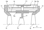
図5は、本発明の振動波モータ1を、例えば光学機器の鏡筒部に組み込んだ適用例を示す要部断面図である。上述の実施形態と重複する構成部材に関しては、同一符号が記されている。
(Application example)
FIG. 5 is a cross-sectional view of a main part showing an application example in which the
第一のレンズ保持部材11は、第一のレンズ14を保持し、第三のレンズ保持部材13は第三のレンズ16を保持している。該第三のレンズ保持部材13の外周部は、筒状部13aを有しており、その先端部13bにおいて、第一のレンズ保持部材11と不図示のネジなどにより締結される。筒状部13aの外径部の一部には、振動波モータ1が固定されるユニット受け部13cが設けられており、公知のネジなどにより着脱自在に固定される。また筒状部13aの内径部には、第二のレンズ15を保持する第二のレンズ保持部材12が配置される。
The first
第二のレンズ15は、合焦レンズとして本発明の振動波モータ1により相対移動の方向A(光軸方向)に沿って移動する。この際、第二のレンズ保持部材12は、軸受け部12aにおいて、公知のガイドバー10と相対的に摺動可能に嵌合しているので、第二のレンズ15を光軸方向に沿って移動させることを可能としている。第二のレンズ保持部材12は、ラック111を介して加圧ガイド部材105の入力部105a(不図示)に接続されている。
The
上述したように本発明は、従来の構成のような振動子100の加圧反力Fb’の受け部としての転動部材108を相対移動の方向Aに沿って振動子100の両側に二列設ける構成を必要としないので、装置の小型化が可能となる。以上、本発明に関わる振動波モータ1を組み込んだ光学機器の鏡筒部に関して、その適用例を詳述したが、本発明は上述の適用例に限定されるものではなく、請求項に記載の範囲に示したものであればどのような形態をとることも可能である。
As described above, in the present invention, the rolling
光学機器などに組み込まれる振動波モータの小型化を実現した。 The size of the vibration wave motor incorporated in optical equipment has been reduced.
1 振動波モータ
100 振動子
102 圧電素子
103 摩擦部材
104 筐体
105 加圧ガイド部材(ガイド部材)
105−1 一端部
105−2 他端部
105a 入力部
105b 加圧部
105c 第一のガイド部
107 カバー部材
107a 第二のガイド部
108 転動部材
A 相対移動の方向
Fa 付勢力(外部からの力)
Fb 加圧力
1
105-1 One end 105-2 The
Fb pressurization
Claims (9)
加圧力を受けて該振動子が加圧接触する摩擦部材と、
前記振動子を前記摩擦部材に対して相対移動の方向にガイドするガイド部材と、
カバー部材と、を有する振動波モータにおいて、
前記ガイド部材は、一端部に外部からの力を受入れる入力部と、前記一端部の反対側に位置する他端部に前記加圧力を前記振動子に付与する加圧部とを有し、
前記入力部と前記加圧部との間には、前記相対移動の方向に沿って延在する第一のガイド部が形成されていて、
前記カバー部材には、前記第一のガイド部に対向して位置する第二のガイド部が形成され、前記第一のガイド部及び前記第二のガイド部が協働することにより前記外部からの力に応じて前記加圧力が働くことを特徴とする振動波モータ。 An oscillator with a piezoelectric element and
A friction member that receives pressure and makes pressure contact with the oscillator,
A guide member that guides the vibrator in the direction of relative movement with respect to the friction member,
In a vibration wave motor having a cover member and
The guide member has an input portion that receives an external force at one end portion and a pressurizing portion that applies the pressing force to the vibrator at the other end portion located on the opposite side of the one end portion.
A first guide portion extending in the direction of the relative movement is formed between the input portion and the pressurizing portion .
A second guide portion located opposite to the first guide portion is formed on the cover member, and the first guide portion and the second guide portion cooperate with each other to form the cover member from the outside. A vibration wave motor characterized in that the pressing force acts according to a force .
前記振動波モータの駆動力によって移動する移動体と、を有することを特徴とする光学機器。 The vibration wave motor according to any one of claims 1 to 8 .
An optical device having a moving body that moves by the driving force of the vibration wave motor .
Priority Applications (2)
| Application Number | Priority Date | Filing Date | Title |
|---|---|---|---|
| JP2016120606A JP6806472B2 (en) | 2016-06-17 | 2016-06-17 | Vibration wave motor and optical equipment to which the vibration wave motor is applied |
| US15/609,466 US10734923B2 (en) | 2016-06-17 | 2017-05-31 | Vibration wave motor and optical device using vibration wave motor |
Applications Claiming Priority (1)
| Application Number | Priority Date | Filing Date | Title |
|---|---|---|---|
| JP2016120606A JP6806472B2 (en) | 2016-06-17 | 2016-06-17 | Vibration wave motor and optical equipment to which the vibration wave motor is applied |
Publications (3)
| Publication Number | Publication Date |
|---|---|
| JP2017225291A JP2017225291A (en) | 2017-12-21 |
| JP2017225291A5 JP2017225291A5 (en) | 2019-07-18 |
| JP6806472B2 true JP6806472B2 (en) | 2021-01-06 |
Family
ID=60660927
Family Applications (1)
| Application Number | Title | Priority Date | Filing Date |
|---|---|---|---|
| JP2016120606A Active JP6806472B2 (en) | 2016-06-17 | 2016-06-17 | Vibration wave motor and optical equipment to which the vibration wave motor is applied |
Country Status (2)
| Country | Link |
|---|---|
| US (1) | US10734923B2 (en) |
| JP (1) | JP6806472B2 (en) |
Families Citing this family (4)
| Publication number | Priority date | Publication date | Assignee | Title |
|---|---|---|---|---|
| DE102014205280B3 (en) * | 2014-03-21 | 2015-06-11 | Physik Instrumente (Pi) Gmbh & Co. Kg | inertial drive |
| JP6788493B2 (en) * | 2016-12-22 | 2020-11-25 | キヤノン株式会社 | Vibration wave motor and equipment using it |
| JP6995660B2 (en) * | 2018-02-15 | 2022-01-14 | キヤノン株式会社 | Drive device with vibration wave motor |
| JP7027237B2 (en) * | 2018-04-17 | 2022-03-01 | キヤノン株式会社 | Mobile device |
Family Cites Families (6)
| Publication number | Priority date | Publication date | Assignee | Title |
|---|---|---|---|---|
| US6218767B1 (en) | 1996-01-08 | 2001-04-17 | Canon Kabushiki Kaisha | Vibration device |
| JP6188366B2 (en) | 2013-03-21 | 2017-08-30 | キヤノン株式会社 | Actuator and optical equipment |
| JP5955347B2 (en) | 2013-04-01 | 2016-07-20 | キヤノン株式会社 | Linear ultrasonic motor and optical apparatus using the same |
| JP2014202908A (en) | 2013-04-04 | 2014-10-27 | キヤノン株式会社 | Optical member driving device and imaging apparatus |
| JP6700945B2 (en) * | 2016-04-28 | 2020-05-27 | キヤノン株式会社 | Vibration wave motor and device using the same |
| JP6910936B2 (en) * | 2017-11-27 | 2021-07-28 | キヤノン株式会社 | Vibration type motors, lens devices, and electronic devices |
-
2016
- 2016-06-17 JP JP2016120606A patent/JP6806472B2/en active Active
-
2017
- 2017-05-31 US US15/609,466 patent/US10734923B2/en active Active
Also Published As
| Publication number | Publication date |
|---|---|
| JP2017225291A (en) | 2017-12-21 |
| US10734923B2 (en) | 2020-08-04 |
| US20170366105A1 (en) | 2017-12-21 |
Similar Documents
| Publication | Publication Date | Title |
|---|---|---|
| JP5955347B2 (en) | Linear ultrasonic motor and optical apparatus using the same | |
| JP6188366B2 (en) | Actuator and optical equipment | |
| JP6808345B2 (en) | Electronic devices equipped with vibration wave motors and vibration wave motors, lens barrels, imaging devices | |
| JP6806472B2 (en) | Vibration wave motor and optical equipment to which the vibration wave motor is applied | |
| JP6366674B2 (en) | Vibration wave motor | |
| JP6329372B2 (en) | Drive device, lens holding device, and motorized device | |
| JP6567020B2 (en) | DRIVE DEVICE, OPTICAL DEVICE, AND IMAGING DEVICE | |
| JP6700945B2 (en) | Vibration wave motor and device using the same | |
| WO2014196212A1 (en) | Linear ultrasonic motor and optical device equipped with same | |
| JP2017200366A (en) | Vibration wave motor and electronic apparatus loading the same | |
| JP6605012B2 (en) | Vibration wave motor and lens driving device using vibration wave motor | |
| JP7112250B2 (en) | Oscillating wave motor and drive | |
| JP6949905B2 (en) | Actuators, devices | |
| WO2016002917A1 (en) | Vibration-type actuator, lens barrel, image-capturing device, and automatic stage | |
| JP6929165B2 (en) | Vibration wave motor and drive | |
| JP2016213974A (en) | Vibration type actuator and ultrasonic motor | |
| JP2019103336A (en) | Driving device and optical instrument | |
| JP2019088048A (en) | Ultrasonic motor, lens device and imaging apparatus | |
| JP6882036B2 (en) | Imaging device with vibration wave motor and vibration wave motor | |
| JP2016101023A (en) | Vibration wave motor and optical device including the same | |
| JP6537482B2 (en) | Vibration wave motor and electronic equipment | |
| JP2021072649A (en) | Vibration-type drive unit and optical instrument | |
| JP2015159725A (en) | Oscillation type motor and lens device including the same | |
| JP2021022999A (en) | Ultrasonic motor | |
| JP2021158761A (en) | Vibration wave motor, and lens barrel driving device with the same |
Legal Events
| Date | Code | Title | Description |
|---|---|---|---|
| RD05 | Notification of revocation of power of attorney |
Free format text: JAPANESE INTERMEDIATE CODE: A7425 Effective date: 20171214 |
|
| RD04 | Notification of resignation of power of attorney |
Free format text: JAPANESE INTERMEDIATE CODE: A7424 Effective date: 20180126 |
|
| A521 | Written amendment |
Free format text: JAPANESE INTERMEDIATE CODE: A523 Effective date: 20190612 |
|
| A621 | Written request for application examination |
Free format text: JAPANESE INTERMEDIATE CODE: A621 Effective date: 20190612 |
|
| A977 | Report on retrieval |
Free format text: JAPANESE INTERMEDIATE CODE: A971007 Effective date: 20200522 |
|
| A131 | Notification of reasons for refusal |
Free format text: JAPANESE INTERMEDIATE CODE: A131 Effective date: 20200616 |
|
| A521 | Written amendment |
Free format text: JAPANESE INTERMEDIATE CODE: A523 Effective date: 20200720 |
|
| TRDD | Decision of grant or rejection written | ||
| A01 | Written decision to grant a patent or to grant a registration (utility model) |
Free format text: JAPANESE INTERMEDIATE CODE: A01 Effective date: 20201105 |
|
| A61 | First payment of annual fees (during grant procedure) |
Free format text: JAPANESE INTERMEDIATE CODE: A61 Effective date: 20201204 |
|
| R151 | Written notification of patent or utility model registration |
Ref document number: 6806472 Country of ref document: JP Free format text: JAPANESE INTERMEDIATE CODE: R151 |