JP6997546B2 - Liquid discharge device, imprint device, printer, and article manufacturing method - Google Patents
Liquid discharge device, imprint device, printer, and article manufacturing method Download PDFInfo
- Publication number
- JP6997546B2 JP6997546B2 JP2017123559A JP2017123559A JP6997546B2 JP 6997546 B2 JP6997546 B2 JP 6997546B2 JP 2017123559 A JP2017123559 A JP 2017123559A JP 2017123559 A JP2017123559 A JP 2017123559A JP 6997546 B2 JP6997546 B2 JP 6997546B2
- Authority
- JP
- Japan
- Prior art keywords
- flow path
- liquid
- discharge
- pressure control
- unit
- Prior art date
- Legal status (The legal status is an assumption and is not a legal conclusion. Google has not performed a legal analysis and makes no representation as to the accuracy of the status listed.)
- Active
Links
Images


Landscapes
- Coating Apparatus (AREA)
- Shaping Of Tube Ends By Bending Or Straightening (AREA)
- Exposure Of Semiconductors, Excluding Electron Or Ion Beam Exposure (AREA)
Description
本発明は、液体吐出装置、インプリント装置、プリンタ、および物品製造方法に関する。 The present invention relates to a liquid ejection device, an imprint device, a printer, and a method for manufacturing an article.
半導体デバイス等の物品を製造するためのリソグラフィー装置の1つとしてインプリント装置が注目されている。インプリント装置は、基板の上にインプリント材を供給し、該インプリント材に型を接触させ、硬化用のエネルギーを与えることにより該インプリント材を硬化させ、これにより型の凹凸パターンが転写された硬化物のパターンを形成する装置である。基板の上にインプリント材を供給するための技術には、インクジェットプリンタの技術、即ち、吐出口からインクを吐出する技術が応用されている。インプリント装置では、インクに代えて、液体状態のインプリント材が吐出口から吐出され、基板の上に供給される。吐出口からインクまたはインプリント材のような液体を吐出させる技術においては、液体に加わる圧力を一定に維持することが重要である。特許文献1には、容器内の気体の圧力を調整するために弾性変形部材を用いた圧力調整室が開示されている。特許文献2には、インク流路にバッファタンクを配置したインクジェット記録装置が開示されている。
Imprint devices are attracting attention as one of the lithography devices for manufacturing articles such as semiconductor devices. The imprint device supplies the imprint material on the substrate, brings the mold into contact with the imprint material, and applies energy for curing to cure the imprint material, whereby the uneven pattern of the mold is transferred. It is a device that forms a pattern of the cured product. Inkjet printer technology, that is, technology for ejecting ink from a ejection port, is applied to the technology for supplying an imprint material on a substrate. In the imprint device, instead of the ink, the imprint material in a liquid state is ejected from the ejection port and supplied onto the substrate. In the technique of ejecting a liquid such as ink or imprint material from the ejection port, it is important to maintain a constant pressure applied to the liquid.
液体が充填された液室および該液室に連通した吐出口を有する吐出部と、該吐出部に接続された流路を介して該液室の圧力を制御する圧力制御部とを有する構成において、メンテナンスのために吐出部を圧力制御部に対して相対的に移動させる必要が生じうる。このような場合において、流路内の液体の慣性力や流路を構成するチューブの変形および振動などによって液室の圧力が不安定になりうる。この場合、圧力が安定するまで長時間にわたって吐出部からの液体の吐出動作を開始することができない。 In a configuration having a liquid chamber filled with a liquid, a discharge unit having a discharge port communicating with the liquid chamber, and a pressure control unit for controlling the pressure of the liquid chamber via a flow path connected to the discharge unit. , It may be necessary to move the discharge section relative to the pressure control section for maintenance. In such a case, the pressure in the liquid chamber may become unstable due to the inertial force of the liquid in the flow path, the deformation and vibration of the tube constituting the flow path, and the like. In this case, the liquid discharge operation from the discharge unit cannot be started for a long time until the pressure stabilizes.
本発明は、上記の課題認識を契機としてなされたものであり、例えば、圧力制御部に対して吐出部を相対的に移動させた場合において液室の圧力を安定させるのに有利な液体吐出装置を提供することを目的とする。 The present invention has been made in the wake of the above-mentioned problem recognition, and is advantageous for stabilizing the pressure in the liquid chamber when the discharge unit is moved relative to the pressure control unit, for example. The purpose is to provide.
本発明の1つの側面は、液体吐出装置に係り、前記液体吐出装置は、液体が充填された液室および前記液室に連通した吐出口を有し、前記液室の中の液体を前記吐出口から吐出する吐出部と、前記吐出部に接続された流路と、前記流路を介して前記液室の圧力を制御する圧力制御部と、前記圧力制御部に対して前記吐出部を相対的に第1方向に沿って移動させる移動機構と、を備え、前記流路は、前記吐出部と前記圧力制御部とを接続する第1流路と、前記吐出部と前記圧力制御部とを接続する第2流路とを有し、前記第1流路と前記第2流路とは、前記第1方向における成分に関して互いに反対方向となる、前記圧力制御部に向かう第2方向を有する第1部分と前記圧力制御部に向かう第3方向を有する第2部分とをそれぞれ有する。 One aspect of the present invention relates to a liquid discharge device, wherein the liquid discharge device has a liquid chamber filled with a liquid and a discharge port communicating with the liquid chamber, and discharges the liquid in the liquid chamber. The discharge unit discharged from the outlet, the flow path connected to the discharge unit, the pressure control unit that controls the pressure of the liquid chamber via the flow path, and the discharge unit relative to the pressure control unit. A moving mechanism for moving along a first direction is provided, and the flow path includes a first flow path connecting the discharge unit and the pressure control unit, and the discharge unit and the pressure control unit. A second flow path having a second flow path to be connected, and the first flow path and the second flow path have a second direction toward the pressure control unit, which is opposite to each other with respect to the components in the first direction. It has one portion and a second portion having a third direction toward the pressure control unit.
本発明によれば、例えば、圧力制御部に対して吐出部を相対的に移動させた場合において液室の圧力を安定させるのに有利な液体吐出装置が提供される。 According to the present invention, for example, there is provided a liquid discharge device that is advantageous for stabilizing the pressure in the liquid chamber when the discharge unit is moved relative to the pressure control unit.
以下、添付図面を参照しながら本発明をその例示的な実施形態を通して説明する。なお、以下では、液体吐出装置をインプリント装置に適用した例を説明した後に、液体吐出装置をプリンタに適用した例を説明する。 Hereinafter, the present invention will be described through an exemplary embodiment with reference to the accompanying drawings. In the following, an example in which the liquid discharge device is applied to the imprint device will be described, and then an example in which the liquid discharge device is applied to the printer will be described.
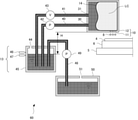
図1には、本発明の1つの実施形態のインプリント装置100の構成が示されている。インプリント装置100は、液体状態のインプリント材8を基板4の上に供給する供給部として、液体吐出装置60を備えている。インプリント装置100は、液体吐出装置60の吐出部10によって基板4の上にインプリント材8を供給し、インプリント材8に型1を接触させ、硬化部7からインプリント材8に硬化用のエネルギーを与えることによりインプリント材8を硬化させる。これにより、型1の凹凸パターンが転写された硬化物のパターンが形成される。
FIG. 1 shows the configuration of the
インプリント材としては、硬化用のエネルギーが与えられることにより硬化する硬化性組成物(未硬化状態の樹脂と呼ぶこともある)が用いられうる。硬化用のエネルギーとしては、電磁波、熱等が用いられうる。電磁波は、例えば、その波長が10nm以上1mm以下の範囲から選択される光、例えば、赤外線、可視光線、紫外線などでありうる。硬化性組成物は、光の照射により、あるいは、加熱により硬化する組成物でありうる。これらのうち、光により硬化する光硬化性組成物は、少なくとも重合性化合物と光重合開始剤とを含有し、必要に応じて非重合性化合物または溶剤を更に含有してもよい。非重合性化合物は、増感剤、水素供与体、内添型離型剤、界面活性剤、酸化防止剤、ポリマー成分などの群から選択される少なくとも一種である。インプリント材は、吐出部10により、液滴状、或いは複数の液滴が繋がってできた島状又は膜状となって基板上に配置されうる。インプリント材の粘度(25℃における粘度)は、例えば、1mPa・s以上100mPa・s以下でありうる。基板の材料としては、例えば、ガラス、セラミックス、金属、半導体、樹脂等が用いられうる。必要に応じて、基板の表面に、基板とは別の材料からなる部材が設けられてもよい。基板は、例えば、シリコンウエハ、化合物半導体ウエハ、石英ガラスである。
As the imprint material, a curable composition (sometimes referred to as an uncured resin) that cures when energy for curing is applied can be used. As the energy for curing, electromagnetic waves, heat and the like can be used. The electromagnetic wave may be, for example, light selected from a wavelength range of 10 nm or more and 1 mm or less, for example, infrared rays, visible rays, ultraviolet rays, and the like. The curable composition can be a composition that cures by irradiation with light or by heating. Of these, the photocurable composition that is cured by light contains at least a polymerizable compound and a photopolymerization initiator, and may further contain a non-polymerizable compound or a solvent, if necessary. The non-polymerizable compound is at least one selected from the group of sensitizers, hydrogen donors, internal release mold release agents, surfactants, antioxidants, polymer components and the like. The imprint material can be arranged on the substrate in the form of droplets or islands or films formed by connecting a plurality of droplets by the
以下では、硬化用のエネルギーとしてUV光(紫外光)を使用し、UV光の照射によってインプリント材を硬化させるように構成されたインプリント装置について例示的に説明するが、前述のように、硬化用のエネルギーとして他のエネルギーが使用されてもよい。 In the following, an imprint device configured to cure the imprint material by using UV light (ultraviolet light) as energy for curing and irradiating with UV light will be exemplified. Other energies may be used as the curing energy.
本明細書および添付図面では、基板4の表面に平行な方向をXY平面とするXYZ座標系において方向を示す。XYZ座標系におけるX軸、Y軸、Z軸にそれぞれ平行な方向をX方向、Y方向、Z方向とし、X軸周りの回転、Y軸周りの回転、Z軸周りの回転をそれぞれθX、θY、θZとする。X軸、Y軸、Z軸に関する制御または駆動は、それぞれX軸に平行な方向、Y軸に平行な方向、Z軸に平行な方向に関する制御または駆動を意味する。また、θX軸、θY軸、θZ軸に関する制御または駆動は、それぞれX軸に平行な軸の周りの回転、Y軸に平行な軸の周りの回転、Z軸に平行な軸の周りの回転に関する制御または駆動を意味する。また、位置は、X軸、Y軸、Z軸の座標に基づいて特定されうる情報であり、姿勢は、θX軸、θY軸、θZ軸の値で特定されうる情報である。位置決めは、位置および/または姿勢を制御することを意味する。
In the present specification and the accompanying drawings, the direction is shown in the XYZ coordinate system in which the direction parallel to the surface of the
インプリント装置100は、基板4を保持し駆動する基板駆動機構6、基板駆動機構6を支持するベースフレーム5、型1を保持し型1を駆動する型駆動機構2、型駆動機構2を支持する構造体3、硬化部7および液体吐出装置60を備えうる。基板駆動機構6および型駆動機構2は、基板4と型1との相対位置が調整されるように基板4および型1の少なくとも一方を駆動する位置決め機構を構成する。基板駆動機構6は、基板4を複数の軸(例えば、X軸、Y軸、θZ軸の3軸)について駆動するように構成されうる。型駆動機構2は、型1を複数の軸(例えば、X軸、Y軸、Z軸、θX軸、θY軸、θZ軸の6軸)について駆動するように構成されうる。
The
ここで、インプリント装置100において実行されるインプリント動作を例示的に説明する。まず、基板駆動機構6によって基板4が保持される。次いで、基板4のインプリント対象のショット領域が液体吐出装置60の吐出部10の下に配置されるように、基板駆動機構6によって基板4が駆動される。そして、基板駆動機構6によって基板4が走査されながら吐出部10の吐出口11からインプリント材8が吐出される。これによってショット領域にインプリント材8が配置される。次いで、基板4のインプリント対象のショット領域が型1の下に配置されるように基板駆動機構6によって基板4が駆動される。次いで、型駆動機構2より型1が降下され、基板駆動機構6および型駆動機構2によって基板4のインプリント対象のショット領域と型1とが位置合わせされる。この際に、不図示のアライメントスコープにより、基板4のアライメントマークと型1のアライメントマークとの相対位置が計測され、この計測結果に基づいて基板駆動機構6および型駆動機構2が制御されうる。
Here, the imprint operation executed in the
次いで、型駆動機構2より型1が更に降下され、基板4のショット領域の上のインプリント材8に型1が押し付けられる。これにより、型1の凹凸パターンの凹部にインプリント材8が充填される。次いで、硬化部7が紫外光9をインプリント材8に照射される。これにより、インプリント材8が硬化され、硬化物のパターンが形成される。次いで、型駆動機構2より型1が更に上昇され、基板4の上の硬化物のパターンから型1が引き離される。以上の工程は、基板4の複数のショット領域に対して順次に実施される。
Next, the
以下、液体吐出装置60の基本的な構成例として、第1~第3の構成例を説明し、その後、第1~第3の構成例に共通する構成として、吐出部10の液室の圧力を安定させるための構成を説明する。なお、以下では、液体吐出装置60の吐出部10から吐出される液体をインプリント材として説明するが、液体吐出装置60の適用分野に応じて、液体として種々の他の材料(例えば、有機材料、無機材料、これらの複合材料など)が使用されうる。例えば、液体吐出装置60がプリンタに適用される場合には、該液体としてインクが使用されうる。
Hereinafter, the first to third configuration examples will be described as basic configuration examples of the
図2には、液体吐出装置60の第1の構成例が示されている。第1の構成例では、液体吐出装置60は、吐出部10、第1流路40、第2流路41、サブタンク45、メインタンク50、メインタンク流路48、送液ポンプ49を含む。吐出部10は、インプリント材8(液体)が充填された液室LCおよび液室LCに連通した吐出口11を有し、液室LCの中のインプリント材8を吐出口11から吐出する。液室LCは、液体タンク12の内部空間である。吐出部10には、吐出口11の他、吐出口11からインプリント材8を吐出させるための不図示の駆動部(例えば、圧電素子又はヒーター素子)が設けられている。吐出口11は、大気(外部空間)に対して連通している。また、吐出口11は、下方を向いて配置されうる。吐出口11からインプリント材8が垂れ落ちることを防止するために、液室LCは、負圧(大気圧より低い状態)に維持されうる。しかし、負圧が強すぎると、吐出口11に空気が侵入し、吐出口11からインプリント材8を吐出することができなくなりうる。そこで、液室LCを適切な負圧状態とするために、サブタンク45を利用して圧力制御部13が構成されうる。
FIG. 2 shows a first configuration example of the
サブタンク45は、サブタンク45内の空寸部(サブタンク45内のインプリント材8の液面より上の空間)を大気(外部空間)に連通させる大気開放口44を有する。第1流路40および第2流路41は、サブタンク45と吐出部10(液室LC)とを接続する流路を構成する。第1流路40および第2流路41の一端は、サブタンク45の内部空間に位置する。より具体的には、第1流路40および第2流路41の一端は、サブタンク45の中のインプリント材8の液面より下方に位置する。第1流路40および第2流路41の他端は、それぞれ、液室LCを構成する液体タンク12の第1接続部30および第2接続部31に接続されている。つまり、サブタンク45の内部空間と液室LCとが第1流路40および第2流路41を介して連通している。吐出口11におけるインプリント材8の圧力は、吐出口11の中にインプリント材8によって形成されるメニスカス(気液界面)と、サブタンク45内のインプリント材8の液面との高低差H(水頭差)によって決定される。サブタンク45内のインプリント材8の液面の高さは、吐出口11に形成されるメニスカスよりも低い位置になるように設定される。
The sub-tank 45 has an
吐出口11の内側には、吐出口11からインプリント材8を吐出させる駆動部(例えば、圧電素子又はヒータ素子)が配置され、該駆動部を動作させることによって吐出口11からインプリント材8が吐出される。吐出口11からインプリント材8が吐出された後、吐出口11の中には毛管力によってインプリント材8が充填される。吐出口11からのインプリント材8の吐出が断続的に行われる期間では、吐出口11からの液体の吐出と、吐出口11の内部へのインプリント材8の充填とが繰り返される。吐出口11からのインプリント材8の吐出によるインプリント材8の減少分は、第1流路40および第2流路41を介してサブタンク45から液室LCに補充される。
A drive unit (for example, a piezoelectric element or a heater element) for discharging the
吐出口11からのインプリント材8の吐出によって、サブタンク45の中のインプリント材8の液面が低下する。サブタンク45には、インプリント材8の液面が下限を下回ったことを検知するセンサ47が設けられている。インプリント材8の液面が下限を下回ったことがセンサ47によって検知されると、送液ポンプ49によってメインタンク50からサブタンク45へインプリント材8が供給される。メインタンク50には、大気(外部空間)に連通する大気開放口51が設けられている。また、サブタンク45には、インプリント材8の液面が上限を上回ったことを検知するセンサ46が設けられている。インプリント材8の液面が上限を上回ったことがセンサ46によって検知されると、送液ポンプ49が停止される。このようにして、サブタンク45内のインプリント材8が上記の下限および上限によって規定される範囲内に制御される。これにより、吐出口11のメニスカスにおける圧力が一定の範囲内になるように制御される。
The liquid level of the
なお、圧力制御部13による圧力制御方法は、水頭差を利用するものに限定されず、例えば、サブタンク45を密閉系とし、サブタンク45内の気体の圧力を制御して吐出口11のメニスカスにおける圧力を制御する構成が採用されてもよい。
The pressure control method by the
図3には、液体吐出装置60の第2の構成例が示されている。第2の構成例では、第1流路40、第2流路41、液室LC(液体タンク12)およびサブタンク45によって循環路を形成し、この循環路を通してインプリント材8を循環させる構成が第1の構成例に対して付加されている。第1流路40にはポンプ42が設けられ、第2流路41には第2流路41を遮断する弁43が設けられる。通常は、ポンプ42中の流路は開放され、インプリント材8の流通が可能な状態にされ、弁43も開放され、インプリント材8の流通が可能な状態にされる。
FIG. 3 shows a second configuration example of the
弁43を開き、ポンプ42を動作させると、サブタンク45中のインプリント材8が第1流路40を経由して液室LCに供給され、液室LCのインプリント材8が第2流路41を経由してサブタンク45に戻る循環路が形成される。このような循環路を形成することによって、必要に応じて、液室LCのインプリント材8をサブタンク45に回収することができる。また、第1流路40および第2流路41を構成するチューブを透過してインプリント材8に侵入した空気や、サブタンク45またはメインタンク50内等においてインプリント材8に侵入した空気が気泡となって液室LCに現れる可能性がある。このような場合に、循環路を通して気泡をサブタンク45まで移動させることによって、気泡を除去することができる。インプリント材8の循環は、吐出口11からインプリント材8を吐出する必要がない期間、例えば、インプリント動作を行っていない期間において行われうる。あるいは、インプリント材8の循環は、ポンプ42の脈動を制限した上で常時行われてもよい。
When the
吐出口11の中のインプリント材8の粘度が増したり乾燥したりすることで吐出不良が発生することがある。それを防ぐために、液室LCの圧力を上昇させることによって吐出口11からインプリント材8を強制的に排出させるメンテナンス動作が行われうる。メンテナンス動作は、弁43を閉じてポンプ42を動作させることによって実施することができる。一定量のインプリント材8が吐出されるか、一定時間にわたってインプリント材8が吐出された後にメンテナンス動作を終了させることができる。
Discharge defects may occur due to an increase in the viscosity of the
ポンプ42は、ポンプ機能を有すればよく、例えば、シリンジポンプ、チューブポンプ、ダイアフラムポンプ、ギアポンプなどを採用することができる。なお、ポンプ42の動作を停止しているときも、第1流路40を通してインプリント材8が流動可能な状態を維持するために、動作停止中に流路が遮断される形式のポンプを採用する場合には、該ポンプをバイパスするバイパス流路を設けられうる。また、該バイパス流路には開閉弁が設けられうる。
The
図4には、液体吐出装置60の第3の構成例が示されている。第3の構成例では、液体タンク12の内部空間は、分離部14によって、インプリント材8を収容する液室LCと、作動液を収容する圧力制御室16とに仕切られている。分離部14は、例えば、可撓性の分離膜によって構成されうる。圧力制御部13は、圧力制御室16および第1流路40よび第2流路41に満たされた作動液を介して液室LCの圧力を制御する。吐出口11からのインプリント材8の吐出方法として、例えば、吐出口11に備えられた圧電素子や発熱抵抗体等のエネルギー発生素子を利用してインプリント材8の液滴を吐出するオンデマンド方式のインクジェット技術を適用可能である。あるいは、吐出口11からのインプリント材8の吐出方法として、液室LCのインプリント材8に背圧を加えることによって連続的にインプリント材8の液滴を形成し、必要な液滴を選別して基板4に到達させるコンテニュアス方式を適用可能である。あるいは、吐出口11からのインプリント材8の吐出方法として、液室LC内のインプリント材8に背圧を加え、吐出口11に設けられた弁を制御することによって吐出口11からインプリント材8の液滴を吐出させる方法を適用可能である。
FIG. 4 shows a third configuration example of the
第1流路40および第2流路41は、サブタンク45と吐出部10の圧力制御室16とを接続する流路を構成する。第1流路40および第2流路41の一端は、サブタンク45の内部空間に位置する。より具体的には、第1流路40および第2流路41の一端は、サブタンク45の中の作動液の液面より下方に位置する。第1流路40および第2流路41の他端は、それぞれ、第1接続部30および第2接続部31を介して圧力制御室16に接続されている。つまり、サブタンク45の内部空間と圧力制御室16とが第1流路40および第2流路41を介して連通している。吐出口11におけるインプリント材8の圧力は、吐出口11の中にインプリント材8によって形成されるメニスカス(気液界面)と、サブタンク45内の作動液の液面との高低差H(水頭差)によって決定される。サブタンク45内の作動液の液面の高さは、吐出口11に形成されるメニスカスよりも低い位置になるように設定される。
The
第3の構成例では、圧力制御部13によって作動液の圧力(圧力制御室16の圧力)を制御することによって分離部14を介して間接的に液室LCの圧力(インプリント材8の圧力)を制御する。この方法は、吐出口11におけるメニスカスの形状を安定化させ、インプリント材8を再現性の良く吐出するために有利であることが確認されている。
In the third configuration example, the pressure of the hydraulic fluid (pressure of the imprint material 8) is indirectly controlled through the
吐出口11からのインプリント材8の吐出によって液室LCのインプリント材8が減少すると、液室LCの容積が減少するように分離部14が変形または移動する。これに応じて、サブタンク45から圧力制御室16に作動液が補充され、作動液を介して液室LCの圧力が制御される。吐出口11からのインプリント材8の吐出によって、サブタンク45内のインプリント材8の液面が低下する。サブタンク45には、インプリント材8の液面が下限を下回ったことを検知するセンサ47が設けられている。インプリント材8の液面が下限を下回ったことがセンサ47によって検知されると、送液ポンプ49によってメインタンク50からサブタンク45へ作動液が供給される。メインタンク50には、大気(外部空間)に連通する大気開放口51が設けられている。また、サブタンク45には、作動液の液面が上限を上回ったことを検知するセンサ46が設けられている。作動液の液面が上限を上回ったことがセンサ46によって検知されると、送液ポンプ49が停止される。このようにして、サブタンク45内の作動液が上記の下限および上限によって規定される範囲内に制御される。これにより、吐出口11のメニスカスにおける圧力が一定の範囲内になるように制御される。
When the
インプリント材8は、それに含まれる異物(微小パーティクル)および金属イオンが極限まで低減されているべきであり、基板4に供給されるまでその状態が維持されるべきである。第3の構成例では、インプリント材8は液室LCに閉じ込められているので、流路を構成するチューブや圧力センサ等に接触することがなく、また、空気との接触も低減される。よって、第3の構成例では、インプリント材8に異物や金属イオンが混入することが抑えられる。
Foreign matter (fine particles) and metal ions contained in the
第1流路40にはポンプ42が設けられ、第2流路41には第2流路41を遮断する弁43が設けられる。通常は、ポンプ42中の流路は開放され、作動液の流通が可能な状態にされ、弁43も開放され、作動液の流通が可能な状態にされる。弁43を開き、ポンプ42を動作させると、サブタンク45中の作動液が第1流路40を経由して圧力制御室16に供給され、圧力制御室16の作動液が第2流路41を経由してサブタンク45に戻る循環路が形成される。この循環路を形成することによって、必要に応じて、圧力制御室16の作動液をサブタンク45に回収することができる。また、第1流路40および第2流路41を構成するチューブを透過して作動液に侵入した空気や、サブタンク45またはメインタンク50内等において作動液に侵入した空気が気泡となって圧力制御室16に現れる可能性がある。このような場合に、循環路を通して気泡をサブタンク45まで移動させることによって、気泡を除去することができる。作動液の循環は、吐出口11からインプリント材8を吐出する必要がない期間、例えば、インプリント動作を行っていない期間において行われうる。あるいは、作動液の循環は、ポンプ42の脈動を制限した上で常時行われてもよい。
The
吐出口11の中のインプリント材8の粘度が増したり乾燥したりすることで吐出不良が発生することがある。それを防ぐために、液室LCの圧力を上昇させることによって吐出口11からインプリント材8を強制的に排出させるメンテナンス動作が行われうる。メンテナンス動作は、弁43を閉じて作動液の流通を遮断し、ポンプ42を動作させることによって実施することができる。一定量のインプリント材8が吐出されるか、一定時間にわたってインプリント材8が吐出された後にメンテナンス動作を終了させることができる。
Discharge defects may occur due to an increase in the viscosity of the
圧力制御部13は、上記のような水頭差を利用した構成に限定されず、他の構成を有してもよい。圧力制御部13の他の構成例としては、例えば、サブタンク45を密閉系とし、サブタンク45の空寸部と圧力源(加圧源、真空源)とを連通させることによって圧力制御室16、更には液室LCの圧力を制御するように構成されうる。ここで、圧力制御室の圧力を検知する圧力センサを配置し、サブタンク45の空寸部と圧力源との間に圧力制御弁を設け、圧力目標値および圧力センサの出力に基づいて圧力制御弁をフィードバック制御しうる。
The
圧力制御部13は、基板4へのインプリント材8の供給時はサブタンク45の空寸分を大気圧として水頭差を利用して液室LCの圧力を制御し、メンテナンス時はサブタンク45を密閉系として圧力源により液室LCの圧力を制御するように構成されてもよい。ここで、メンテナンス時は、圧力源によって圧力制御室16を介して液室LCを加圧することによって強制的に吐出口11からインプリント材8を吐出させる動作がなされうる。
When the
図5に例示されるように、インプリント装置100は、液体吐出装置60の吐出部10を所定方向(第1方向)に沿って移動させる移動機構20を備えうる。移動機構20は、複数の位置に吐出部10を位置決めすることができるように構成されうる。複数の位置は、例えば、基板4にインプリント材8を供給する動作を実施する供給位置、および、メンテタンス動作を実施するメンテナンス位置を含みうる。メンテナンス位置では、例えば、受け皿21に対してインプリント材を吐出して吐出口11の不具合(例えば、吐出量の減少、不吐出)を解消したり、吐出精度を検査したりする動作が行われうる。移動機構20は、ボールネジまたはリニアモータを含みうる。
As illustrated in FIG. 5, the
インプリント装置100では、全ショット領域に対するインプリント動作が終了した基板をアンロードされてから未処理の基板をロードされるまでの限られた時間内にメンテナンス動作が実行されうる。そのため、移動機構20によって吐出部10を移動させる際の加速度を大きくする必要がある。圧力制御部13(サブタンク45)に対して吐出部10を相対的に移動させるために、第1流路40および第2流路41を構成するチューブは、屈曲可能なチューブで構成される。図6(a)、(b)には、吐出部10が移動するときの第1流路40および第2流路41の配置が例示されている。通常は、圧力制御部13の位置は固定されていて、吐出部10が図6(a)、(b)における左右方向(X方向)に移動する。
In the
本実施形態では、吐出部10と圧力制御部13とを接続する流路が、吐出部10と圧力制御部13とを接続する第1流路40と、吐出部10と圧力制御部13とを接続する第2流路41とを有する。第1流路40は、第1流路40を通して吐出部10から圧力制御部13に向かう経路において進行方向が第2方向(+X方向)に一致する第1部分22を含む。第2流路41は、第2流路41を通して吐出部10から圧力制御部13に向かう経路において進行方向が第3方向(-X方向)に一致する第2部分23を含む。ここで、第2方向は、移動機構20が吐出部10を搬送する方向である第1方向(±X方向)に直交するように吐出部10を通る仮想平面VPから仮想平面VPの一方の側(図6では右側)に向かって離れる方向であり、例えば、第1方向と平行な方向である。第3方向は、仮想平面VPから仮想平面VPの他方の側(図6では左側)に向かって離れる方向であり、例えば、第1方向と平行な方向である。図6(a)、(b)では、第2方向と第3方向とは、互いに反対方向(互いに180度異なる方向)である。第1流路40は、第1流路40を通して吐出部10から圧力制御部13に向かう経路において進行方向が第3方向(-X方向)に一致する第3部分22を含む。第2流路41は、第2流路41を通して吐出部10から圧力制御部13に向かう経路において進行方向が第2方向(+X方向)に一致する第4部分25を含む。
In the present embodiment, the flow path connecting the
第1流路40および第2流路41の形状は、吐出部10の移動に伴って変化する。また、第1流路40は、吐出部10と圧力制御部13との間に第1屈曲部70を形成し、第2流路41は、吐出部10と圧力制御部13との間に第2屈曲部71を形成する。第1屈曲部70および第2屈曲部71は、吐出部10の移動に伴って移動する。第1部分22は、第1屈曲部70と吐出部10との間に形成されうる。第2部分23は、第2屈曲部71と吐出部10との間に形成されうる。第3部分24は、第1屈曲部70と圧力制御部13との間に形成されうる。第4部分25は、第2屈曲部71と圧力制御部13との間に形成されうる。第1部分22、第2部分23、第3部分24および第4部分25の長さおよび位置は、吐出部10の移動に伴って変化する。
The shapes of the
あるいは、第1流路40、第2流路41は、圧力制御部13に向かう第2方向を有する第1部分22、圧力制御部13に向かう第3方向を有する第2部分23をそれぞれ有するものとして理解することもできる。ここで、第2方向と第3方向とは、第1方向(±X方向)における成分に関して、互いに反対方向である。換言すると、第2方向が有する第1方向(±X方向)における成分と、第3方向が有する第1方向(±X方向)における成分とは、互いに反対方向である。
Alternatively, the
なお、第2方向は、第1方向と直交する場合は、第1方向の成分を有しない。同様に、第3方向は、第1方向と直交する場合は、第1方向の成分を有しない。よって、例えば、第2方向は、+X方向に対して反時計回りに0°以上90°未満の角度をなし、第3方向は、+X方向に対して反時計回りに90°より大きく180°以下の角度をなすものとする。第2方向に係る当該角度は、第2方向を有するベクトルを定義した場合に、その大きさに対する、当該ベクトルの第1方向における成分の大きさの比率が、それには限定されないが、例えば50%以上の第1比率となるようにするのが好ましい。また、第3方向に係る当該角度は、第3方向を有するベクトルを定義した場合に、その大きさに対する、当該ベクトルの第1方向における成分の大きさの比率が、それには限定されないが、例えば上記第1比率に等しくなるようにするのが好ましい。 When the second direction is orthogonal to the first direction, the second direction has no component in the first direction. Similarly, the third direction has no component of the first direction if it is orthogonal to the first direction. Therefore, for example, the second direction makes an angle of 0 ° or more and less than 90 ° counterclockwise with respect to the + X direction, and the third direction is more than 90 ° counterclockwise with respect to the + X direction and 180 ° or less. It shall form the angle of. The angle relating to the second direction is, for example, 50%, for example, when a vector having the second direction is defined, the ratio of the size of the component in the first direction of the vector to the size thereof is not limited thereto. It is preferable to have the above first ratio. Further, the angle related to the third direction is not limited to, for example, the ratio of the size of the component in the first direction of the vector to the size of the vector when the vector having the third direction is defined. It is preferable that the ratio is equal to the first ratio.
上記のような構成によれば、吐出部10の移動によって第1流路40内のインプリント材が受ける影響(例えば、動圧)の全部または一部が吐出部10の移動によって第2流路41内のインプリント材が受ける影響(例えば、動圧)によって相殺されうる。また、上記の構成によれば、吐出部10の移動によって第1流路40および第2流路41内のインプリント材が受ける影響は、インプリント材が圧力制御部13のサブタンク45を通して流動することによって低減される。また、上記の構成によれば、吐出部10の移動によって第1流路40および第2流路41内のインプリント材が受ける影響は、インプリント材が圧力制御部13の液体タンク12(液室LCまたは圧力制御室16)を通して流動することによって低減される。したがって、上記のような構成によれば、圧力制御部13に対して吐出部10を相対的に移動させたときの吐出部10の液室LCの圧力の変動を低減すること、即ち、液室LCの圧力を安定させることができる。そのため、移動機構20によって吐出部10を移動させる際の加速度あるいは速度を高くすることができ、これによりメンテナンスのために要する時間を短縮し、スループットを向上させることができる。このような効果は、第1および第2の構成例における液室LCの容積または第3の構成例における圧力制御室16の容積が小さくても得られる。
第1流路40と液体タンク12を接続する第1接続部30および第2流路41と液体タンク12を接続する第2接続部31は、それらをインプリント材が流れる方向が第1方向(±X方向)に平行な方向となるように構成されうるが、これには限定されない。
According to the above configuration, all or part of the influence (for example, dynamic pressure) on the imprint material in the
In the first connecting
図7(a)~(c)には、図6に示された実施形態の変形例が示されている。図7(a)~(c)に示される変形例も、図6に示された実施形態と同様の特徴を有する。即ち、第1流路40は、第1流路40を通して吐出部10から圧力制御部13に向かう経路において進行方向が第2方向(+X方向)に一致する第1部分22を含む。また、第2流路41は、第2流路41を通して吐出部10から圧力制御部13に向かう経路において進行方向が第3方向(-X方向)に一致する第2部分23を含む。また、第1流路40は、第1流路40を通して吐出部10から圧力制御部13に向かう経路において進行方向が第3方向(-X方向)に一致する第3部分22を含む。また、第2流路41は、第2流路41を通して吐出部10から圧力制御部13に向かう経路において進行方向が第2方向(+X方向)に一致する第4部分25を含む。
7 (a) to 7 (c) show modified examples of the embodiment shown in FIG. The modified examples shown in FIGS. 7 (a) to 7 (c) have the same characteristics as those of the embodiment shown in FIG. That is, the
あるいは、該変形例も、第1流路40、第2流路41は、圧力制御部13に向かう第2方向を有する第1部分22、圧力制御部13に向かう第3方向を有する第2部分23をそれぞれ有するものとして理解することもできる。ここで、第2方向と第3方向とは、第1方向(±X方向)における成分に関して、互いに反対方向である。換言すると、第2方向が有する第1方向(±X方向)における成分と、第3方向が有する第1方向(±X方向)における成分とは、互いに反対方向である。
Alternatively, also in the modification, the
図7(a)に示された変形例では、第1接続部30および第2接続部31は、それらをインプリント材が流れる方向が第1方向(±X方向)に交差する方向(例えば、第1方向に直交する方向)となるように構成されている。また、図7(a)に示された変形例では、第1接続部30および第2接続部31は、吐出部10の液体タンク12の複数の面のうち第1方向に平行な面に配置されている。図7(b)に示された変形例では、第1接続部30および第2接続部31は、吐出部10の液体タンク12の複数の面のうち第1方向と直交または交差する1つの面に配置されている。図7(c)に示された変形例では、液体タンク12には、2つの接続部が共通化された1つの第1共通接続部32が設けられ、圧力制御部13のサブタンク45には、2つの接続部が共有化された1つの第2共通接続部33が設けられている。第1流路40は、第1共通接続部32と第2共通接続部33とを接続する1つの経路を構成し、第2流路41は、第1共通接続部32と第2共通接続部33とを接続する他の経路を構成する。
In the modified example shown in FIG. 7A, the first connecting
図3に示された第2の構成例および図4に示された第3の構成例では、第1流路40にポンプ42が設けられ、第2流路41に弁43が設けられている。このような構成では、少なくとも移動機構20が吐出部10を移動させる速度が変化している期間は、弁43が開放状態にされる。また、このような構成では、動作停止中に流路が遮断される形式のポンプを採用する場合には、該ポンプをバイパスするバイパス流路を設けられる。そして、少なくとも移動機構20が吐出部10を移動させる速度が変化している期間は、該バイパス流路が有効化、即ち、流通可能な状態にされる。
In the second configuration example shown in FIG. 3 and the third configuration example shown in FIG. 4, the
上記の実施形態の効果は、図8を参照しながら以下で説明される比較例と比較すると理解しやすい。図8に示された比較例では、吐出部10と圧力制御部13とは単一の流路80によって接続されている。つまり、比較例は、第1部分22を含む第1流路40および第2部分23を含む第2流路41を有しない。比較例において、図8(a)に示されるように、吐出部10が右方向に移動するために加速をするとき、流路80のうち吐出部10の移動と共に右方向に加速する部分82の中に存在するインプリント材は、その慣性力によって動圧を生じさせる。この動圧は、液体タンク12の内部の圧力を大きくさせる。また、比較例において、図8(b)に示される位置へ移動が完了する直前の減速の加速度によって、吐出部10の移動と共に減速する部分85の中に存在するインプリント材は、その慣性力によって動圧を生じさせる。この動圧は、液体タンク12の内部の圧力を小ささせる。
The effects of the above embodiments are easy to understand when compared with the comparative examples described below with reference to FIG. In the comparative example shown in FIG. 8, the
したがって、吐出部10の移動に伴って動圧が発生し、この動圧によって液体タンク12内の圧力が変動し、これが吐出口11のメニスカスを不安定にさせる。また、吐出部10の移動に伴って流路80を構成するチューブが変形したり振動したりしうる。これによっても液体タンク12内の圧力が変更しうる。液体タンク12内の圧力の変動によってメニスカスが振動すると、吐出口11から吐出されるインプリント材の吐出量や吐出速度にばらつきが生じる原因となる。したがって、振動が減衰してメニスカスが安定するまでの間、吐出口11からインプリント材を吐出することができず、これによって液体吐出装置およびインプリント装置のスループットが悪化する。また、液室LCの圧力が大きくなると、メニスカスが破れて吐出口11の周囲にインプリント材が溢れ出る可能性がある。液室LCの圧力が小さくなると、メニスカスが後退して吐出口11の中に空気(気泡)が入り、液体の吐出不良が生じる可能性がある。
Therefore, a dynamic pressure is generated as the
また、液室の圧力を安定させるのにあたって動圧の影響について考慮した構成を説明したが、それに加えて、またはそれに替えて、静圧の影響について考慮した構成としてもよい。例えば、液体と配管とを含む第1流路40と、液体と配管とを含む第2流路41とが互いに同等または同程度の質量であるか、両質量の差が許容範囲内に収まっていればよい。この場合、吐出部10に対して第1流路40から加えられる静圧と、吐出部10に対して第2流路41から加えられる静圧とが互いに同等または同程度になるか、両静圧の差が許容範囲内に収まる。これにより、移動機構20による吐出部10の移動に伴って生じうる液室LCの圧力の変化を許容範囲内に収めることができる。また、第1流路40の重心の高さ(Z軸方向の位置)と、第2流路41の重心の高さ(Z軸方向の位置)とが同等または同程度である(両高さの差が許容範囲内に収まっている)と、液室LCの圧力の変化を許容範囲内に収めるのに有利である。
Further, although the configuration in which the influence of the dynamic pressure is taken into consideration in stabilizing the pressure in the liquid chamber has been described, a configuration in which the influence of the static pressure is taken into consideration may be used in addition to or instead of the configuration. For example, the
インプリント装置を用いて形成した硬化物のパターンは、各種物品の少なくとも一部に恒久的に、或いは各種物品を製造する際に一時的に、用いられる。物品とは、電気回路素子、光学素子、MEMS、記録素子、センサ、或いは、型等である。電気回路素子としては、DRAM、SRAM、フラッシュメモリ、MRAMのような、揮発性或いは不揮発性の半導体メモリや、LSI、CCD、イメージセンサ、FPGAのような半導体素子等が挙げられる。型としては、インプリント用のモールド等が挙げられる。 The pattern of the cured product formed by using the imprint device is used permanently for at least a part of various articles or temporarily when manufacturing various articles. The article is an electric circuit element, an optical element, a MEMS, a recording element, a sensor, a mold, or the like. Examples of the electric circuit element include volatile or non-volatile semiconductor memories such as DRAM, SRAM, flash memory, and MRAM, and semiconductor elements such as LSI, CCD, image sensor, and FPGA. Examples of the mold include a mold for imprinting.
硬化物のパターンは、上記物品の少なくとも一部の構成部材として、そのまま用いられるか、或いは、レジストマスクとして一時的に用いられる。基板の加工工程においてエッチング又はイオン注入等が行われた後、レジストマスクは除去される。 The pattern of the cured product is used as it is as a constituent member of at least a part of the above-mentioned article, or is temporarily used as a resist mask. After etching or ion implantation in the substrate processing step, the resist mask is removed.
次に、物品製造方法の具体例を説明する。図9(a)に示すように、絶縁体等の被加工材2zが表面に形成されたシリコンウエハ等の基板4zを用意し、続いて、インクジェット法等により、被加工材2zの表面にインプリント材3zを付与する。ここでは、複数の液滴状になったインプリント材3zが基板上に付与された様子を示している。
Next, a specific example of the article manufacturing method will be described. As shown in FIG. 9A, a
図9(b)に示すように、インプリント用の型1zを、その凹凸パターンが形成された側を基板上のインプリント材3zに向け、対向させる。図9(c)に示すように、インプリント材3zが付与された基板4と型1zとを接触させ、圧力を加える。インプリント材3zは型1zと被加工材2zとの隙間に充填される。この状態で硬化用のエネルギーとして光を型1zを透して照射すると、インプリント材3zは硬化する。
As shown in FIG. 9B, the imprint mold 1z is opposed to the
図9(d)に示すように、インプリント材3zを硬化させた後、型1zと基板4zを引き離すと、基板4z上にインプリント材3zの硬化物のパターンが形成される。この硬化物のパターンは、型の凹部が硬化物の凸部に、型の凹部が硬化物の凸部に対応した形状になっており、即ち、インプリント材3zに型1zの凹凸パターンが転写されたことになる。
As shown in FIG. 9D, when the
図9(e)に示すように、硬化物のパターンを耐エッチングマスクとしてエッチングを行うと、被加工材2zの表面のうち、硬化物が無いか或いは薄く残存した部分が除去され、溝5zとなる。図9(f)に示すように、硬化物のパターンを除去すると、被加工材2zの表面に溝5zが形成された物品を得ることができる。ここでは硬化物のパターンを除去したが、加工後も除去せずに、例えば、半導体素子等に含まれる層間絶縁用の膜、つまり、物品の構成部材として利用してもよい。
As shown in FIG. 9E, when etching is performed using the pattern of the cured product as an etching resistant mask, the portion of the surface of the work material 2z where the cured product is absent or remains thin is removed, and the
以下、液体吐出装置60をプリンタに適用した例を説明する。1つの適用例におけるプリンタでは、インクを吐出する吐出部10とサブタンク45とが離隔して配置され、1色あたり2本のチューブ(第1流路40、第2流路)によって接続され、吐出部10を往復移動しながら画像を形成する。カラープリンタでは、例えば、シアンインク、マゼンタインク、イエローインクを用いて減法混色法で被記録媒体上にカラー画像を形成する。したがって、カラープリンタでは、1色のインクに対して少なくとも1つの液体吐出装置60が設けられる。
Hereinafter, an example in which the
10:吐出部、11:吐出口、12 液体タンク、13:圧力制御部、20:移動機構、22:第1部分、23:第2部分、24:第3部分、25:第4部分、40:第1流路、41:第2流路、5:サブタンク、60:液体吐出装置、100:インプリント装置、VP:仮想平面 10: Discharge part, 11: Discharge port, 12 Liquid tank, 13: Pressure control part, 20: Movement mechanism, 22: 1st part, 23: 2nd part, 24: 3rd part, 25: 4th part, 40 : 1st flow path, 41: 2nd flow path, 5: Sub tank, 60: Liquid discharge device, 100: Imprint device, VP: Virtual plane
Claims (15)
前記流路は、前記吐出部と前記圧力制御部とを接続する第1流路と、前記吐出部と前記圧力制御部とを接続する第2流路とを有し、前記第1流路と前記第2流路とは、前記第1方向における成分に関して互いに反対方向となる、前記圧力制御部に向かう第2方向を有する第1部分と前記圧力制御部に向かう第3方向を有する第2部分とをそれぞれ有する、ことを特徴とする液体吐出装置。 A liquid chamber filled with a liquid and a discharge port communicating with the liquid chamber, a discharge portion for discharging the liquid in the liquid chamber from the discharge port, a flow path connected to the discharge portion, and the above. A pressure control unit that controls the pressure of the liquid chamber via the flow path and a moving mechanism that moves the discharge unit relative to the pressure control unit along the first direction are provided.
The flow path has a first flow path connecting the discharge unit and the pressure control unit, and a second flow path connecting the discharge unit and the pressure control unit, and the first flow path and the flow path. The second flow path is a first portion having a second direction toward the pressure control unit and a second portion having a third direction toward the pressure control unit, which are opposite to each other with respect to the components in the first direction. A liquid discharge device characterized by having each of the above.
ことを特徴とする請求項1に記載の液体吐出装置。 The flow path constitutes a circulation path passing through the discharge unit and the pressure control unit.
The liquid discharge device according to claim 1.
ことを特徴とする請求項1に記載の液体吐出装置。 The discharge unit is provided with a first common connection unit, the pressure control unit is provided with a second common connection unit, and the first flow path includes the first common connection unit and the second common connection unit. The second flow path constitutes another path connecting the first common connection portion and the second common connection portion.
The liquid discharge device according to claim 1.
ことを特徴とする請求項1乃至3のいずれか1項に記載の液体吐出装置。 The pressure control unit includes a tank for accommodating a liquid, the discharge unit is configured to discharge the liquid downward from the discharge port, and the pressure in the liquid chamber is the liquid level of the liquid in the tank. Is controlled by the height difference between the liquid level and the liquid level in the discharge port.
The liquid discharge device according to any one of claims 1 to 3.
ことを特徴とする請求項1乃至4のいずれか1項に記載の液体吐出装置。 A pump arranged in the first flow path is provided.
The liquid discharge device according to any one of claims 1 to 4.
ことを特徴とする請求項1乃至5のいずれか1項に記載の液体吐出装置。 A valve arranged in the second flow path.
The liquid discharge device according to any one of claims 1 to 5.
ことを特徴とする請求項6に記載の液体吐出装置。 The valve is opened at least during a period in which the speed at which the moving mechanism moves the discharge portion is changing.
The liquid discharge device according to claim 6.
ことを特徴とする請求項1乃至7のいずれか1項に記載の液体吐出装置。 The discharge unit has a pressure control chamber separated from the liquid chamber by a separation unit, and the pressure control unit measures the pressure in the liquid chamber through the pressure control chamber and the hydraulic fluid filled in the flow path. To control,
The liquid discharge device according to any one of claims 1 to 7.
ことを特徴とする請求項1乃至7のいずれか1項に記載の液体吐出装置。 The pressure control unit communicates with the liquid chamber via the flow path.
The liquid discharge device according to any one of claims 1 to 7.
ことを特徴とする請求項1乃至9のいずれか1項に記載の液体吐出装置。 The second direction and the third direction are parallel to the first direction.
The liquid discharge device according to any one of claims 1 to 9.
ことを特徴とする請求項1乃至10のいずれか1項に記載の液体吐出装置。 The first flow path and the second flow path are a static pressure applied to the discharge portion from the first flow path and a static pressure applied to the discharge portion from the second flow path. The difference is configured to be within the acceptable range,
The liquid discharge device according to any one of claims 1 to 10.
前記流路は、前記吐出部と前記圧力制御部とを接続する第1流路と、前記吐出部と前記圧力制御部とを接続する第2流路とを有し、前記第1流路と前記第2流路とは、前記吐出部に対して前記第1流路から加えられる静圧と、前記吐出部に対して前記第2流路から加えられる静圧との差が許容範囲内に収まるように構成されている、ことを特徴とする液体吐出装置。 A liquid chamber filled with a liquid and a discharge port communicating with the liquid chamber, a discharge portion for discharging the liquid in the liquid chamber from the discharge port, a flow path connected to the discharge portion, and the above. A pressure control unit that controls the pressure of the liquid chamber via the flow path and a moving mechanism that moves the discharge unit along the first direction are provided.
The flow path has a first flow path connecting the discharge unit and the pressure control unit, and a second flow path connecting the discharge unit and the pressure control unit, and the first flow path and the flow path. With respect to the second flow path, the difference between the static pressure applied to the discharge portion from the first flow path and the static pressure applied to the discharge portion from the second flow path is within an allowable range. A liquid discharge device characterized in that it is configured to fit.
ことを特徴とするインプリント装置。 An imprint device having a supply unit for supplying an imprint material on a substrate and forming a pattern from the imprint material supplied on the substrate by the supply unit, according to a claim as the supply unit. The liquid discharge device according to any one of 1 to 12 is provided.
An imprint device characterized by that.
前記工程で前記パターンを形成された前記基板を加工する工程と、
を含むことを特徴とする物品製造方法。 A step of forming a pattern on a substrate by the imprinting apparatus according to claim 13.
A step of processing the substrate on which the pattern is formed in the step and a step of processing the substrate.
A method for manufacturing an article, which comprises.
Applications Claiming Priority (2)
| Application Number | Priority Date | Filing Date | Title |
|---|---|---|---|
| JP2016125917 | 2016-06-24 | ||
| JP2016125917 | 2016-06-24 |
Publications (3)
| Publication Number | Publication Date |
|---|---|
| JP2018006747A JP2018006747A (en) | 2018-01-11 |
| JP2018006747A5 JP2018006747A5 (en) | 2020-08-06 |
| JP6997546B2 true JP6997546B2 (en) | 2022-01-17 |
Family
ID=60950001
Family Applications (1)
| Application Number | Title | Priority Date | Filing Date |
|---|---|---|---|
| JP2017123559A Active JP6997546B2 (en) | 2016-06-24 | 2017-06-23 | Liquid discharge device, imprint device, printer, and article manufacturing method |
Country Status (1)
| Country | Link |
|---|---|
| JP (1) | JP6997546B2 (en) |
Families Citing this family (6)
| Publication number | Priority date | Publication date | Assignee | Title |
|---|---|---|---|---|
| JP7071196B2 (en) * | 2018-04-05 | 2022-05-18 | キヤノン株式会社 | Discharge material Discharge device and imprint device |
| US11193506B2 (en) * | 2018-11-15 | 2021-12-07 | Canon Kabushiki Kaisha | Pulsation dampener with gas retention |
| JP7134847B2 (en) * | 2018-11-28 | 2022-09-12 | キヤノン株式会社 | Discharge material discharge device and imprint device |
| JP7195906B2 (en) * | 2018-12-10 | 2022-12-26 | キヤノン株式会社 | Discharge material discharge device and imprint device |
| JP7374679B2 (en) * | 2019-09-11 | 2023-11-07 | キヤノン株式会社 | Imprint device and imprint device control method |
| JP7391596B2 (en) * | 2019-10-08 | 2023-12-05 | キヤノン株式会社 | imprint device |
Citations (3)
| Publication number | Priority date | Publication date | Assignee | Title |
|---|---|---|---|---|
| JP2015018966A (en) | 2013-07-11 | 2015-01-29 | 大日本印刷株式会社 | Imprint apparatus and imprint method |
| WO2015181924A1 (en) | 2014-05-29 | 2015-12-03 | キヤノン株式会社 | Coating device, imprint device, and method for manufacturing goods |
| JP2016032103A (en) | 2014-07-25 | 2016-03-07 | キヤノン株式会社 | Liquid discharge apparatus, imprint apparatus, and article manufacturing method |
-
2017
- 2017-06-23 JP JP2017123559A patent/JP6997546B2/en active Active
Patent Citations (3)
| Publication number | Priority date | Publication date | Assignee | Title |
|---|---|---|---|---|
| JP2015018966A (en) | 2013-07-11 | 2015-01-29 | 大日本印刷株式会社 | Imprint apparatus and imprint method |
| WO2015181924A1 (en) | 2014-05-29 | 2015-12-03 | キヤノン株式会社 | Coating device, imprint device, and method for manufacturing goods |
| JP2016032103A (en) | 2014-07-25 | 2016-03-07 | キヤノン株式会社 | Liquid discharge apparatus, imprint apparatus, and article manufacturing method |
Also Published As
| Publication number | Publication date |
|---|---|
| JP2018006747A (en) | 2018-01-11 |
Similar Documents
| Publication | Publication Date | Title |
|---|---|---|
| JP6997546B2 (en) | Liquid discharge device, imprint device, printer, and article manufacturing method | |
| TWI649789B (en) | Imprint device, imprint method, and article manufacturing method | |
| CN111093836B (en) | System and method for controlling placement of fluid resist droplets | |
| JP7210155B2 (en) | Apparatus, methods, and methods of making articles | |
| JP6714378B2 (en) | Imprint apparatus and article manufacturing method | |
| JP7309433B2 (en) | Storage device | |
| JP6700949B2 (en) | Imprint method and article manufacturing method | |
| JP2015233100A (en) | Imprint device and article manufacturing method | |
| TWI645955B (en) | Imprinting equipment, method of manufacturing articles and supply equipment | |
| JP2017208424A (en) | Imprint device and manufacturing method of article | |
| KR102030888B1 (en) | Liquid discharge apparatus, imprint apparatus, and method of manufacturing article | |
| KR102316054B1 (en) | Mould, imprint apparatus, method of manufacturing article | |
| JP2021048192A (en) | Imprint device and manufacturing method of article | |
| KR20160137372A (en) | Imprint apparatus and article manufacturing method | |
| JP6898785B2 (en) | Imprint equipment and article manufacturing method | |
| US11520227B2 (en) | Ejection material filling device, pressure regulation device, and ejection material filling method | |
| JP2019125619A (en) | Discharge device and imprint device | |
| US11526074B2 (en) | Molding apparatus for molding composition on substrate using mold, molding method, and method for manufacturing article | |
| JP2014008669A (en) | Image forming method and droplet discharging device | |
| KR102211390B1 (en) | Imprint device and article manufacturing method | |
| US20240083173A1 (en) | Liquid ejection apparatus, imprint apparatus, and ejection method | |
| JP2019079926A (en) | Imprint device, and article manufacturing method | |
| JP2023123123A (en) | Liquid discharge device and imprint device | |
| JP2022096996A (en) | Discharge device, imprint device and method for producing article | |
| TW202408819A (en) | Droplet ejector and method for producing printed matter |
Legal Events
| Date | Code | Title | Description |
|---|---|---|---|
| A521 | Written amendment |
Free format text: JAPANESE INTERMEDIATE CODE: A523 Effective date: 20200618 |
|
| A621 | Written request for application examination |
Free format text: JAPANESE INTERMEDIATE CODE: A621 Effective date: 20200618 |
|
| RD01 | Notification of change of attorney |
Free format text: JAPANESE INTERMEDIATE CODE: A7421 Effective date: 20210103 |
|
| A521 | Written amendment |
Free format text: JAPANESE INTERMEDIATE CODE: A523 Effective date: 20210113 |
|
| A977 | Report on retrieval |
Free format text: JAPANESE INTERMEDIATE CODE: A971007 Effective date: 20210412 |
|
| A131 | Notification of reasons for refusal |
Free format text: JAPANESE INTERMEDIATE CODE: A131 Effective date: 20210423 |
|
| A521 | Written amendment |
Free format text: JAPANESE INTERMEDIATE CODE: A523 Effective date: 20210621 |
|
| TRDD | Decision of grant or rejection written | ||
| A01 | Written decision to grant a patent or to grant a registration (utility model) |
Free format text: JAPANESE INTERMEDIATE CODE: A01 Effective date: 20211119 |
|
| A61 | First payment of annual fees (during grant procedure) |
Free format text: JAPANESE INTERMEDIATE CODE: A61 Effective date: 20211217 |
|
| R151 | Written notification of patent or utility model registration |
Ref document number: 6997546 Country of ref document: JP Free format text: JAPANESE INTERMEDIATE CODE: R151 |