JP6954597B2 - Magnetic levitation transfer device - Google Patents
Magnetic levitation transfer device Download PDFInfo
- Publication number
- JP6954597B2 JP6954597B2 JP2017103313A JP2017103313A JP6954597B2 JP 6954597 B2 JP6954597 B2 JP 6954597B2 JP 2017103313 A JP2017103313 A JP 2017103313A JP 2017103313 A JP2017103313 A JP 2017103313A JP 6954597 B2 JP6954597 B2 JP 6954597B2
- Authority
- JP
- Japan
- Prior art keywords
- magnet
- transport
- pair
- moving direction
- magnets
- Prior art date
- Legal status (The legal status is an assumption and is not a legal conclusion. Google has not performed a legal analysis and makes no representation as to the accuracy of the status listed.)
- Active
Links
Images


Description
本発明は、半導体製造装置や食品製造装置等の、清浄環境中で使用される搬送装置に関
し、特に磁力を利用して搬送台を非接触にて浮上搬送することを特徴とした磁気式浮上搬
送装置に関するものである。
The present invention relates to a transport device used in a clean environment, such as a semiconductor manufacturing device and a food manufacturing device, and is characterized in that the transport table is floated and transported in a non-contact manner by using a magnetic force. It is about the device.
例えば、半導体製造装置では半導体ウエハなどの物品を真空容器中で移動させる搬送装
置が使用される。このような半導体製造装置で使用される搬送装置では、真空容器内の清
浄度を維持するため、搬送台の移動による発塵を極限まで低減させる必要があり、発塵を
低下させるためには搬送台を非接触にて浮上保持させ移動させることが有効である。
For example, in a semiconductor manufacturing apparatus, a conveying apparatus for moving an article such as a semiconductor wafer in a vacuum container is used. In the transfer device used in such a semiconductor manufacturing device, in order to maintain the cleanliness inside the vacuum container, it is necessary to reduce the dust generation due to the movement of the transfer table to the utmost limit, and in order to reduce the dust generation, the transfer device is used. It is effective to float and hold the table in a non-contact manner and move it.
磁力を応用して搬送台を非接触にて浮上保持し移動させる磁気式浮上搬送装置の例とし
て、特許文献1では図7に示すような磁気式浮上搬送装置が提示されている。この特許文
献1の磁気式浮上搬送装置は、容器910の中に永久磁石912を取付けた浮上体911
を配置し、容器910の外部に電磁石917を取付けた可動の案内子915と案内子91
5を移動させるための駆動機構916とを設け、永久磁石912と電磁石917の磁気相
互作用により浮上体911が案内子915の移動に追従するようにしている。
また、案内子915には位置センサ919を取り付け、図示しない制御手段により電磁
石917の励磁電流を制御して永久磁石912と電磁石917によって浮上体911を浮
上させる。これにより非接触にて浮上保持すると共に、非接触にて移動可能とした磁気浮
上搬送装置が示されている。
Patent Document 1 presents a magnetic levitation transfer device as shown in FIG. 7 as an example of a magnetic levitation transfer device that floats, holds, and moves a transfer table by applying magnetic force. The magnetic levitation transport device of Patent Document 1 is a
A
Further, a
しかしながらこのような磁気浮上搬送装置では電磁石および位置センサと制御手段が必
要で、装置が大掛かりとなり複雑化するとともに高価になるという課題があった。
However, such a magnetic levitation transfer device requires an electromagnet, a position sensor, and a control means, and has a problem that the device becomes large-scale, complicated, and expensive.
このような課題を解決する方法として特許文献2では、図8に示すように、部品を載置
する載置台970と、載置台970を支持する支持部971と、支持部971の下方に設
けられた浮力を得るための第一の磁石手段973aを有する浮力受け部973と、支持部
971あるいは支持部971の下方に設けられた吸引される第二の磁石手段972aを有
する被牽引部972と、第一の磁石手段973a、第二の磁石手段972aに対向して配
置された第三の磁石手段961d、第四の磁石手段963とを備え、第一の磁石手段97
3a、第三の磁石手段961dによる磁力によって載置台970を浮上させると共に、第
二の磁石手段972aを吸引しながら第四の磁石手段963を移動させることによって載
置台970を移動可能に構成した部品搬送装置が示されている。
As a method for solving such a problem, in Patent Document 2, as shown in FIG. 8, a mounting table 970 on which parts are mounted, a
3a, a component configured so that the mounting table 970 can be moved by moving the fourth magnet means 963 while attracting the second magnet means 972a while floating the mounting table 970 by the magnetic force of the third magnet means 961d. The transport device is shown.
特許文献2によれば、載置台970は第一の磁石手段973aと第三の磁石手段961
dの間に働く磁力により浮上するので電磁石や制御手段は不要で、磁気浮上搬送装置を簡
略な構造で構成できる。
According to Patent Document 2, the mounting table 970 has a first magnet means 973a and a third magnet means 961.
Since it floats by the magnetic force acting during d, no electromagnet or control means is required, and the magnetic levitation transfer device can be configured with a simple structure.
以上のように、特許文献2に示されている磁気浮上搬送装置は、電磁石や制御手段を用
いずに永久磁石のみで磁気浮上搬送を実現できる優れた構造である。しかしながら、浮力
受け部973に設けられた第1の磁石手段973aと、筐体の外側において移動可能に設
けられた牽引車に設けられた第3の磁石手段961dの磁力により部品を載置する載置台
970を浮上させる構造となっているため、筐体内の清浄度を維持するには、第1の磁石
手段973aと第3の磁石手段961dが筐体の壁部をはさんで対向する構造とする必要
があった。このため筐体の構造が複雑となり筐体の断面構造を磁気浮上搬送装置にあわせ
て都度設計、製作しなければならない、と言う課題があった。
As described above, the magnetic levitation transfer device shown in Patent Document 2 has an excellent structure capable of realizing magnetic levitation transfer only with a permanent magnet without using an electromagnet or a control means. However, the parts are placed by the magnetic force of the first magnet means 973a provided on the
本発明は上記の問題点に鑑みてなされたものであり、永久磁石のみで構成され、筐体に
容易に組み込み可能な磁気浮上搬送装置を提供することを目的とする。
The present invention has been made in view of the above problems, and an object of the present invention is to provide a magnetic levitation transfer device which is composed of only permanent magnets and can be easily incorporated into a housing.
本発明の磁気式浮上搬送装置における請求項1に係る発明は、
清浄環境中で使用される搬送装置であって、基台と、磁力で前記基台から浮上保持される
搬送台を有する磁気式浮上機構と、非接触にて前記搬送台を移動させる磁気式送り機構を
有する磁気式浮上搬送装置において、
前記磁気式浮上機構は前記搬送台を上方に付勢する第1の磁石対と前記搬送台を下方に付
勢する第2の磁石対よりなり、前記第1の磁石対および前記第2の磁石対はそれぞれ、互
いに反発する前記搬送台側の磁石と前記基台側の磁石により構成され、
前記第1の磁石対および前記第2の磁石対の前記搬送台側の前記磁石および前記基台側の
前記磁石はいずれも複数の磁石片を前記搬送台の移動方向に並べて構成されていることを
特徴とする。
The invention according to claim 1 in the magnetic levitation transport device of the present invention
A transport device used in a clean environment, a magnetic levitation mechanism having a base and a transport base that is levitated and held from the base by magnetic force, and a magnetic feed that moves the transport base in a non-contact manner. In a magnetic levitation transfer device having a mechanism
The magnetic levitation mechanism comprises a first magnet pair for urging the carrier upward and a second magnet pair for urging the carrier downward, the first magnet pair and the second magnet. Each pair is composed of a magnet on the transport base side and a magnet on the base side that repel each other.
The magnet on the transport table side and the magnet on the base side of the first magnet pair and the second magnet pair are all configured by arranging a plurality of magnet pieces in the moving direction of the transport table. It is characterized by.
本発明によれば、搬送台を上方に付勢する第1の磁石対と下方に付勢する第2の磁石対
を設けることにより、重さの異なる被搬送物が搬送台に乗せられた場合でも搬送台の浮上
量の変動を小さく抑えることができるので、永久磁石のみで磁気浮上機構が構成できる。
また、搬送台を上方に付勢する第1の磁石対を構成する磁石および搬送台を下方に付勢
する第2の磁石対を構成する磁石の全てを独立した磁石としたので、磁石の仕様を個別に
調整し所望の浮上特性を実現することが可能となると共に、第1の磁石対を構成する磁石
と第2の磁石対を構成する磁石に温度特性が異なる磁石を用いることにより、温度変化に
よる浮上特性の変化を小さくすることが可能となる。
また、第1の磁石対および第2の磁石対を構成する磁石を搬送台の移動方向に並べた磁
石片としたので、搬送距離が長くなっても磁石片の使用数を増やすだけで対応できる。ま
た、第1の磁石対および第2の磁石対を構成する搬送台側磁石と基台側磁石を筐体壁等で
隔離する必要がないので、磁気浮上機構全体を筐体内に入れることが可能となる。
これらにより、用途や企画に応じた大きさの磁気浮上機構を容易に製作でき、磁気浮上
機構全体を筐体内に入れられるので、筐体に容易に組み込み可能な磁気浮上機構が提供で
きる。
According to the present invention, by providing a first magnet pair for urging the carrier upward and a second magnet pair for urging the carrier downward, objects having different weights are placed on the carrier. However, since the fluctuation of the levitation amount of the transport table can be suppressed to be small, the magnetic levitation mechanism can be configured only with a permanent magnet.
Further, since all the magnets constituting the first magnet pair for urging the transport table upward and the magnets constituting the second magnet pair for urging the transport table downward are independent magnets, so that the magnet specifications are used. Can be individually adjusted to achieve the desired levitation characteristics, and by using magnets with different temperature characteristics for the magnets that make up the first magnet pair and the magnets that make up the second magnet pair, the temperature It is possible to reduce the change in levitation characteristics due to the change.
Further, since the magnets constituting the first magnet pair and the second magnet pair are arranged in the moving direction of the transport table as a magnet piece, even if the transport distance becomes long, it can be dealt with only by increasing the number of magnet pieces used. .. Further, since it is not necessary to separate the transport base side magnet and the base side magnet constituting the first magnet pair and the second magnet pair by the housing wall or the like, the entire magnetic levitation mechanism can be put in the housing. It becomes.
As a result, a magnetic levitation mechanism having a size according to the application and plan can be easily manufactured, and the entire magnetic levitation mechanism can be put in the housing, so that a magnetic levitation mechanism that can be easily incorporated into the housing can be provided.
また、本発明の請求項2に係る発明は、前記第1の磁石対を構成する前記搬送台側の前
記複数の磁石片および前記基台側の前記複数の磁石片の少なくともどちらか一方の前記複
数の磁石片は、前記搬送台の移動方向と交差する端面が移動方向に対し傾斜していること
を特徴とする。
Further, the invention according to claim 2 of the present invention is the invention of at least one of the plurality of magnet pieces on the transport base side and the plurality of magnet pieces on the base side, which constitute the first magnet pair. The plurality of magnet pieces are characterized in that the end faces intersecting the moving direction of the transport table are inclined with respect to the moving direction.
搬送台を上方に付勢する第1の磁石対の、搬送台側の複数の磁石片および基台側の複数
の磁石片の少なくともどちらか一方の複数の磁石片の、移動方向と交差する端面を移動方
向に対し傾斜させ、相手側の磁石と対向する面の形状が略平行四辺形状となる形状とした
。これにより、搬送台が移動してすれ違う時の浮上力変動等が小さくなるので、浮上特性
および搬送特性がより安定した磁気式浮上搬送装置を提供することができる。
End faces of a plurality of magnet pieces of the first magnet pair for urging the carrier upward, at least one of a plurality of magnet pieces on the carrier side and a plurality of magnet pieces on the base side, intersecting the moving direction. Was tilted with respect to the moving direction so that the shape of the surface facing the magnet on the other side was a substantially parallel quadrilateral shape. As a result, fluctuations in the levitation force when the transfer table moves and passes each other are reduced, so that it is possible to provide a magnetic levitation transfer device having more stable levitation characteristics and transfer characteristics.
また、本発明の請求項3に係る発明は、前記第2の磁石対を構成する前記搬送台側の前
記複数の磁石片および前記基台側の前記複数の磁石片の少なくともどちらか一方の前記複
数の磁石片は、前記搬送台の移動方向と交差する端面が移動方向に対し傾斜していること
を特徴とする。
Further, the invention according to
搬送台を下方に付勢する第2の磁石対の、搬送台側の複数の磁石片および基台側の複数
の磁石片の少なくともどちらか一方の複数の磁石片の、移動方向と交差する端面を移動方
向に対し傾斜させ、相手側の磁石と対向する面の形状が略平行四辺形状となる形状とした
。これにより、搬送台が移動してすれ違う時の浮上力変動等が小さくなるので、浮上特性
および搬送特性がより安定した磁気式浮上搬送装置を提供することができる。
The end faces of the second magnet pair that biases the carrier downward, at least one of the plurality of magnet pieces on the carrier side and the plurality of magnet pieces on the base side, intersecting the moving direction. Was tilted with respect to the moving direction so that the shape of the surface facing the magnet on the other side was a substantially parallel quadrilateral shape. As a result, fluctuations in the levitation force when the transfer table moves and passes each other are reduced, so that it is possible to provide a magnetic levitation transfer device having more stable levitation characteristics and transfer characteristics.
また、本発明における請求項4に係る発明は、前記第1の磁石対および前記第2の磁石
対の少なくともどちらか一方の磁石対の、それぞれの前記基台側の前記磁石片と前記搬送
台側の前記磁石片の搬送台移動方向の長さが異なることを特徴とする。
Further, the invention according to
本発明では、第1の磁石対および第2の磁石対の少なくともどちらか一方の磁石対の、
対向する基台側磁石片と搬送台側磁石片の長さが異なるので、搬送台が移動した際に複数
の磁石片の端面が同時にすれ違うことがないので、磁石片が切り替わる時の浮上力変動お
よびコギング力が分散して発生するので、浮上特性および搬送特性がより安定した磁気式
浮上搬送装置を提供することができる。
In the present invention, of at least one of the first magnet pair and the second magnet pair,
Since the lengths of the opposing base side magnet pieces and the transport base side magnet pieces are different, the end faces of multiple magnet pieces do not pass each other at the same time when the transport base moves, so the levitation force fluctuates when the magnet pieces are switched. And since the cogging force is dispersed and generated, it is possible to provide a magnetic levitation transfer device having more stable levitation characteristics and transfer characteristics.
また、本発明における請求項5に係る発明は、前記第1の磁石対を前記搬送台移動方向
と直交する方向の幅の両端部側にそれぞれ設け、2つの前記第1の磁石対の前記基台側の
前記磁石の搬送台移動方向と直交する方向の幅間隔と、2つの前記第1の磁石対の前記搬
送台側の前記磁石の搬送台移動方向と直交する方向の幅間隔が異なり、幅間隔が狭いほう
の2つの前記磁石が、幅間隔が広いほうの2つの前記磁石の間にあることを特徴とする。
Further, in the invention according to the fifth aspect of the present invention, the first magnet pair is provided on both end sides of the width in the direction orthogonal to the transport table moving direction, respectively, and the base of the two first magnet pairs. The width interval in the direction orthogonal to the transport table moving direction of the magnet on the table side and the width interval in the direction orthogonal to the transport table moving direction of the magnet on the transport table side of the two first magnet pairs are different. The two magnets having a narrower width spacing are located between the two magnets having a wider width spacing.
本発明では、搬送台を上方に付勢する第1の磁石対を搬送台の幅方向両端部側にそれぞ
れ設け、例えば基台側の2つの磁石の幅間隔が搬送台側の2つの磁石の幅間隔より広く、
幅間隔の広い基台側の2つの磁石の間に幅間隔の狭い搬送台側の2つの磁石が入り込む構
成とした。
これにより、何らかの外力等により搬送台が幅方向にずれるように付勢された場合に、
この付勢力が搬送台側磁石と基台側磁石の反発力により低減されるので、より安定した磁
気式浮上搬送装置を提供することができる。
In the present invention, first magnet pairs for urging the carrier upward are provided on both ends in the width direction of the carrier, and for example, the width interval between the two magnets on the base side is the width of the two magnets on the carrier side. Wider than the width interval,
The two magnets on the carrier side with a narrow width interval are inserted between the two magnets on the base side with a wide interval.
As a result, when the carrier is urged to shift in the width direction due to some external force or the like,
Since this urging force is reduced by the repulsive force of the transport base side magnet and the base side magnet, a more stable magnetic levitation transport device can be provided.
また、本発明における請求項6に係る発明は、前記第2の磁石対を前記搬送台移動方向
と直交する方向の幅の両端部側にそれぞれ設け、2つの前記第2の磁石対の前記基台側の
前記磁石の搬送台移動方向と直交する方向の幅間隔と、2つの前記第2の磁石対の前記搬
送台側の前記磁石の搬送台移動方向と直交する方向の幅間隔が異なり、幅間隔が狭いほう
の2つの前記磁石が、幅間隔が広いほうの2つの前記磁石の間にあることを特徴とする。
Further, in the invention according to
本発明では、搬送台を下方に付勢する第2の磁石対を搬送台の幅方向両端部側にそれぞ
れ設け、例えば基台側の2つの磁石の幅間隔が搬送台側の2つの磁石の幅間隔より広く、
幅間隔の広い基台側の2つの磁石の間に幅間隔の狭い搬送台側の2つの磁石が入り込む構
成とした。
これにより、何らかの外力等により搬送台が幅方向にずれるように付勢された場合に、
この付勢力が搬送台側磁石と基台側磁石の反発力により低減されるので、より安定した磁
気式浮上搬送装置を提供することができる。
In the present invention, second magnet pairs for urging the carrier downward are provided on both ends in the width direction of the carrier, and for example, the width interval between the two magnets on the base side is the width of the two magnets on the carrier side. Wider than the width interval,
The two magnets on the carrier side with a narrow width interval are inserted between the two magnets on the base side with a wide interval.
As a result, when the carrier is urged to shift in the width direction due to some external force or the like,
Since this urging force is reduced by the repulsive force of the transport base side magnet and the base side magnet, a more stable magnetic levitation transport device can be provided.
また、本発明における請求項7に係る発明は、前記磁気式送り機構は、前記搬送台の移
動方向と直交する回転軸を有する円筒状のピニオン磁石と、複数個の磁石片が前記搬送台
の移動方向に並べられたラック磁石よりなり、前記複数個の磁石片よりなる前記ラック磁
石の前記搬送台の移動方向の長さは、前記第1の磁石対の前記搬送台側の前記磁石の前記
搬送台の移動方向の長さより短いことを特徴とする。
Further, in the invention according to
本発明では、磁気式送り機構を構成するラック磁石の搬送台移動方向の長さを、第1の
磁石対の搬送台側の磁石の搬送台移動方向の長さより短くしたので、搬送台が移動方向に
傾斜した場合、第1の磁石対の搬送台側磁石と基台側磁石の反発力により、傾斜が低減す
る方向に搬送台が付勢される。
これにより、搬送台が移動方向に傾斜した場合でも搬送台の吸着を避け傾斜を低減させ
ることが可能となり、より安定した磁気式浮上搬送装置を提供することができる。
In the present invention, the length of the rack magnets constituting the magnetic feed mechanism in the moving direction of the carrier is shorter than the length of the magnets on the carrier side of the first magnet pair in the moving direction of the carrier, so that the carrier moves. When tilted in the direction, the transport base is urged in the direction in which the tilt is reduced by the repulsive force of the transport base side magnet and the base side magnet of the first magnet pair.
As a result, even when the transport table is tilted in the moving direction, it is possible to avoid suction of the transport table and reduce the tilt, and it is possible to provide a more stable magnetic levitation transport device.
また、本発明における請求項8に係る発明は、前記第1の磁石対を前記搬送台搬送方向と直交する方向の幅の両端部側にそれぞれ設け、前記搬送台を移動させる前記磁気式送り機構を、前記搬送台の幅の両端部側に設けた前記第1の磁石対より前記搬送台の幅の中央寄りに配置したことを特徴とする。 Further, in the invention according to
本発明では In the present invention
基台側磁石および搬送台側の磁石からなる第1の磁石対は反発力により搬送台を上方に付勢する。これに対し、ラック磁石とピニオン磁石からなる磁気式送り機構では、ラック磁石とピニオン磁石間の吸引力により搬送台を下方に付勢する。The first magnet pair composed of the base side magnet and the transport base side magnet urges the transport base upward by a repulsive force. On the other hand, in the magnetic feed mechanism including the rack magnet and the pinion magnet, the carrier is urged downward by the attractive force between the rack magnet and the pinion magnet.
何らかの理由で搬送台が傾斜した場合、搬送台は幅の略中央を中心に回転し、幅の両端部の一方は上方に移動し他方は下方に移動する。下方に移動した端部側の第1の磁石対の基台側磁石と搬送台側の磁石は近接し、搬送台をより強く上方に付勢し搬送台の傾斜を低減させる様な力が働く。これに対し磁気式送り機構はラック磁石とピニオン磁石の距離が近づくと吸引力が増加して搬送台の傾斜を増加させる様な力が発生する。 If the carrier is tilted for some reason, the carrier will rotate around approximately the center of the width, with one end of the width moving upwards and the other moving downwards. The magnets on the base side and the magnets on the transport base side of the first magnet pair on the end side that have moved downward are close to each other, and a force that urges the transport base more strongly upward and reduces the inclination of the transport base acts. .. On the other hand, in the magnetic feed mechanism, as the distance between the rack magnet and the pinion magnet approaches, the attractive force increases and a force that increases the inclination of the transport table is generated.
本発明では磁気式送り機構を搬送台の幅の両端部側に設けた2つの第1の磁石対の間に配置したので、搬送台が傾斜した場合、傾斜によりラック磁石とピニオン磁石の距離が近づく量より搬送台の幅の端部側に設けた第1の磁石対の基台側磁石と搬送台側の磁石が近接する量のほうが必ず大きくなるので、磁気式送り機構による搬送台の傾斜を増加させる力より第1の磁石対による搬送台の傾斜を低減させる力のほうが大きくなり搬送台は水平に戻される。 In the present invention, the magnetic feed mechanism is arranged between the two first magnet pairs provided on both ends of the width of the transport table. Therefore, when the transport table is tilted, the distance between the rack magnet and the pinion magnet is increased due to the tilt. Since the amount in which the base-side magnet of the first magnet pair provided on the end side of the width of the transfer table and the magnet on the transfer table side are in close proximity to each other is always larger than the approach amount, the transfer table is tilted by the magnetic feed mechanism. The force for reducing the inclination of the transport table by the first magnet pair becomes larger than the force for increasing the force, and the transport table is returned to the horizontal position.
これにより、搬送台が幅方向に傾斜した場合でも搬送台の吸着を避け傾斜を低減させることが可能となり、より安定した磁気式浮上搬送装置を提供することができる。 As a result, even when the transport table is tilted in the width direction, it is possible to avoid suction of the transport table and reduce the tilt, and it is possible to provide a more stable magnetic levitation transport device.
以上により、本発明による磁気式浮上搬送装置では、
搬送台を上方に付勢する第1の磁石対と下方に付勢する第2の磁石対を設けることによ
り、永久磁石のみで磁気浮上機構が構成でき、
磁石対の磁石を移動方向に並べた磁石片としたので、搬送距離が長くなっても磁石片の
使用数を増やすだけで用途や企画に応じた大きさの磁気浮上機構を容易に製作でき、
搬送台側磁石と基台側磁石を筐体壁で分離する必要がないので、筐体に容易に組み込み
可能な磁気浮上機構を提供することができる。
As described above, in the magnetic levitation transfer device according to the present invention,
By providing a first magnet pair that biases the carrier upward and a second magnet pair that biases the carrier downward, the magnetic levitation mechanism can be configured with only permanent magnets.
Since the magnet pieces of the magnet pair are arranged in the direction of movement, even if the transport distance is long, it is possible to easily manufacture a magnetic levitation mechanism of a size according to the application and plan simply by increasing the number of magnet pieces used.
Since it is not necessary to separate the transport base side magnet and the base side magnet by the housing wall, it is possible to provide a magnetic levitation mechanism that can be easily incorporated into the housing.
本発明に係る磁気式浮上搬送装置の実施例を、図1から図5を参照に、詳細に説明する
。
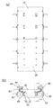
はじめに、本実施例による磁気式浮上搬送装置の外観および概略構造を、図1および図
2を参照に説明する。なお、本実施例の説明中では図2中に方向指示矢印記号にて示す、
Xの方向を「移動方向X」、Yの方向を「幅方向Y」、Zの方向を「高さ方向Z」と記述
する。
An embodiment of the magnetic levitation transport device according to the present invention will be described in detail with reference to FIGS. 1 to 5.
First, the appearance and schematic structure of the magnetic levitation transfer device according to the present embodiment will be described with reference to FIGS. 1 and 2. In the description of this embodiment, the direction indicating arrow symbol is shown in FIG.
The direction of X is described as "moving direction X", the direction of Y is described as "width direction Y", and the direction of Z is described as "height direction Z".
本実施例による磁気式浮上搬送装置は、図1および図2に示すように、略板状の基台1
0と、同じく略板状で、被搬送物を載置し基台10から浮上して保持され、基台10の長
手方向、すなわち移動方向Xに搬送される搬送台20、搬送台20を非接触で搬送する磁
気式送り機構50などより構成される。
As shown in FIGS. 1 and 2, the magnetic levitation transport device according to the present embodiment has a substantially plate-shaped base 1.
In the same manner as 0, the
磁気式浮上搬送装置の幅方向の両端部側にはそれぞれ、搬送台20を上方に付勢する第
1の磁石対30と搬送台を下方に付勢する第2の磁石対40が設けられている。また、幅
方向Yの両端部側に設けられた2つの第1の磁石対30および第2の磁石対40より中央
よりの位置に、ラック磁石51およびピニオン磁石52よりなる磁気式送り機構50が設
けられている。
A
搬送台20を上方に付勢する第1の磁石対30は、図3(a)に示すように、台座81
を介して基台10の上面側に取り付けられた基台側磁石31と搬送台20の下面側に取り
付けられた搬送台側磁石32よりなる。基台側磁石31と搬送台側磁石32は互いに反発
するような極性の配置としてあるので、第1の磁石対30の搬送台側磁石32は第1の磁
石対30の基台側磁石31により上方に付勢される。
As shown in FIG. 3A, the
It is composed of a
また、搬送台20を下方に付勢する第2の磁石対40は、基台10の上面の両側端に固
定された側板82の上面に固定された天板83の下面に取付けられた基台側磁石41と搬
送台20の上面側に取り付けられた搬送台側磁石42よりなる。基台側磁石41と搬送台
側磁石42は互いに反発するような極性の配置としてあるので、第2の磁石対40の搬送
台側磁石42は天板83の下面に取付けられた第2の磁石対40の基台側磁石41により
下方に付勢される。
Further, the
第1の磁石対30および第2の磁石対40のそれぞれの基台側磁石31,41および搬
送台側磁石32,42は、図3(a)に示すように、それぞれ複数の磁石片31a,41
a,32a,42aが移動方向Xに複数個並べられており、第1の磁石対30および第2
の磁石対40のそれぞれの基台側磁石31,41は基台10の移動方向Xの長さの略全長
にわたり並べられている。同様に第1の磁石対30および第2の磁石対40のそれぞれの
搬送台側磁石32,42は搬送台20の移動方向Xの長さの略全長にわたり並べられてい
る。
As shown in FIG. 3A, the base-
A plurality of a, 32a, 42a are arranged in the moving direction X, and the
The base-
上記のように本発明による磁気浮上搬送装置では、第1の磁石対30および第2の磁石
対40を構成する磁石を、移動方向Xに並べた複数個の磁石片としたので、用途目的等に
より搬送距離が変更されても磁石片の使用数を増減するだけで対応でき、柔軟な修正対応
が可能となる。
As described above, in the magnetic levitation transfer device according to the present invention, the magnets constituting the
また、本発明による磁気浮上搬送装置搬送台では、図3(b)に示すように、搬送台2
0の下面に移動方向Xに並べられた複数個の磁石片51aよりなるラック磁石51と、移
動方向Xと直交する幅方向Yと平行な向きの回転軸を有し、移動方向Xに複数個配置され
たピニオン磁石52よりなる磁気式送り機構50により、搬送台20を非接触で移動させ
る。
Further, in the magnetic levitation transfer device transfer table according to the present invention, as shown in FIG. 3 (b), the transfer table 2
It has a
ラック磁石51は隣接する個々の磁石片51aの極性が互いに異なるように並べられる
。また略円筒状のピニオン磁石52の円筒形状側面部は円周方向に並ぶ複数の領域に分割
され、隣接する領域が互いに異なる極性となるように着磁されている。
The
ラック磁石51とピニオン磁石52はギャップを介して対向しており、複数のピニオン
磁石52が図示しない回転手段により回転させられると、ラック磁石51とピニオン磁石
52の磁気的な吸引力によりラック磁石51は移動方向Xに移動し、ラック磁石51が取
り付けられている搬送台20が非接触で移動させられる。
The
なお、本発明による磁気浮上搬送装置では物品を置載して搬送する搬送台を浮上させる
磁気式浮上機構を、搬送台を上方に付勢する第1の磁石対30と搬送台を下方に付勢する
第2の磁石対40を有する構成とした。
In the magnetic levitation transfer device according to the present invention, a magnetic levitation mechanism for levitation of a transfer table on which an article is placed and conveyed is attached, and a
搬送台を上方および下方の両方向に付勢して搬送台を浮上させる構造は、図8に概略の
構成を示した特許文献2にも記載されており、浮力受け部973が第1の磁石手段973
aと第3の磁石手段961dの反発力で上方に付勢されるとともにガイド部961の上部
下面961eと浮力受け部の上面973bの反発力で下方に付勢される構成が示されてい
る。しかしながら上部下面961eと浮力受け部の上面973bの反発力による下方への
付勢の機能および効果は特許文献2には記載されていない。
A structure in which the carrier is urged in both the upper and lower directions to raise the carrier is also described in Patent Document 2 whose schematic configuration is shown in FIG. 8, and the
A configuration is shown in which the repulsive force of a and the third magnet means 961d is urged upward, and the repulsive force of the upper
本発明による磁気浮上搬送装置でも搬送台20を上方に付勢するとともに下方にも付勢
する構成としており、本発明におけるこの構成の機能および効果を以下に記述する。
The magnetic levitation transport device according to the present invention also has a configuration in which the
この構成の第1の機能は、上方への付勢により搬送台を浮上させ、下方への付勢により
搬送台20が上昇しすぎて天板83等と接触することを回避することである。
The first function of this configuration is to raise the transport table by upward urging, and to prevent the transfer table 20 from rising too much due to downward urging and coming into contact with the
しかしながら、より重要なこの構成の第2の機能は、搬送台20の浮上特性の調整であ
る。搬送台20を上方および下方の両方向に付勢する構成とした場合の、第1の磁石対3
0および第2の磁石対40の付勢力の特性および結果として得られる搬送台20の浮上特
性の解析結果を、図6を参照して説明する。
However, a more important second function of this configuration is the adjustment of the levitation characteristics of the
The analysis result of the urging force characteristic of the 0 and the
図6は第1の磁石対30および第2の磁石対40の大きさ、磁石間距離等の寸法仕様を
仮に設定して解析した結果で、横軸が第1の磁石対30の基台側磁石31と搬送台側磁石
32の磁石間距離で、縦軸は発生する付勢力である。付勢力は、図6のグラフ中に破線で
記入した第1の磁石対30に発生する搬送台20を上方に付勢する「上方付勢力」と、図
6のグラフ中に一点鎖線で記入した第2の磁石対40に発生する搬送台20を下方に付勢
する「下方付勢力」および、図6のグラフ中に実線で記入した上方付勢力と下方付勢力を
足し合せた「総合付勢力」を求めた。総合付勢力は第1の磁石対30および第2の磁石対
40により搬送台20が実際に受ける付勢力である。
FIG. 6 shows the results of tentatively setting and analyzing dimensional specifications such as the size of the
なお、本解析では解析対象である複数の磁石および搬送台,基台等の自重は考慮してい
ない。また、第2の磁石対40に発生する下方付勢力は搬送台20を下方に付勢するため
マイナスの値となる。
In this analysis, the weights of multiple magnets to be analyzed, the carrier, the base, etc. are not taken into consideration. Further, the downward urging force generated on the
図6のグラフに記載のように、第1の磁石対30に発生する上方付勢力は、磁石間距離
が10mmの時に約10kN発生し、磁石間距離が6mmの時には約15kN発生する。
同様に第2の磁石対40に発生する下方付勢力は、磁石間距離が10mmの時に約−7k
N発生し、磁石間距離が6mmの時には約−5kN発生する。この結果、上方付勢力と下
方付勢力を足し合せた総合付勢力は、磁石間距離が10mmの時に約3.4kN、磁石間
距離が6mmの時には9.5kNの上向きの付勢力となる。
As described in the graph of FIG. 6, the upward urging force generated in the
Similarly, the downward urging force generated in the
N is generated, and when the distance between magnets is 6 mm, about -5 kN is generated. As a result, the total urging force obtained by adding the upward urging force and the downward urging force is about 3.4 kN when the distance between the magnets is 10 mm, and 9.5 kN when the distance between the magnets is 6 mm.
上記の「総合付勢力」の解析結果は、搬送台20を下向きに3.4kNで押すと磁石間
距離が10mmの位置で釣り合い、9.5kNで押すと磁石間距離が6mmで釣り合う、
という事を意味している。この釣り合い挙動から、搬送台20を下向きに4.8kNで押
すと磁石間距離は9mmとなる。
以上より、搬送台20にかかる力が3.4kNから4.8kNに変化、すなわち1.4
kN増えた場合、磁石間距離は10mmから9mmに、すなわち1mmだけ減少する。
The above analysis result of "total urging force" shows that when the
It means that. From this equilibrium behavior, when the transport table 20 is pushed downward at 4.8 kN, the distance between the magnets becomes 9 mm.
From the above, the force applied to the transport table 20 changes from 3.4 kN to 4.8 kN, that is, 1.4.
When kN is increased, the distance between magnets is reduced from 10 mm to 9 mm, that is, by 1 mm.
ところで、単に搬送台20を浮上させるのであれば第1の磁石対30による上方への付
勢のみでも良い。そこで、例えば第1の磁石対30の磁気特性を調整し、具体的には磁力
を弱くし、磁石間距離が10mmの時の付勢力が総合付勢力と同じ3.4kNになる様に
した場合の上方への付勢力を求めた。この結果を図6に「算出_上方付勢力」として2点
鎖線で記入した。
By the way, if the transport table 20 is simply levitated, only the upward urging by the
この、磁石対を第1の磁石対のみとして磁気特性を調整した「算出_上方付勢力」では
、図6のグラフに記載のように、搬送台20を下向きに3.4kNで押すと磁石間距離が
10mmの位置で釣り合い、4.8kNで押すと磁石間距離が6mmで釣り合う。
従って、搬送台20にかかる力が3.4kNから4.8kNに変化、すなわち1.4k
N増えた場合、磁石間距離は10mmから6mmに、すなわち4mm減少する。
In this "calculation_upward urging force" in which the magnetic characteristics are adjusted by using only the first magnet pair as the magnet pair, when the
Therefore, the force applied to the transport table 20 changes from 3.4 kN to 4.8 kN, that is, 1.4 k.
When N increases, the distance between magnets decreases from 10 mm to 6 mm, that is, 4 mm.
以上のことから、図6に示す磁石対の寸法仕様を仮設定した解析結果では、搬送台20
にかかる力が1.4kN増えた場合、搬送台20を上方に付勢する磁石対のみで浮上させ
ると磁石間距離が4mm変化するが、搬送台を上方に付勢する第1の磁石対30と下方に
付勢する第2の磁石対40を設けると磁石間距離の変化量は1mmに抑えられる。
From the above, in the analysis result in which the dimensional specifications of the magnet pair shown in FIG. 6 are tentatively set, the transport table 20 is used.
When the force applied to the
このように、搬送台20を上方に付勢する第1の磁石対30と下方に付勢する第2の磁
石対40を設け、搬送台20への上方の付勢力を下方への付勢力により一部相殺させるこ
とにより、重さの異なる被搬送物が搬送台20に乗せられた場合でも搬送台20の浮上量
の変動を小さく抑えることができるという効果が得られ、この結果 永久磁石のみで安定
して浮上保持できる磁気浮上機構を構成することが可能となる。
In this way, the
なお、上記の付勢力の挙動特性は磁石対の寸法仕様を特定の値に仮設定した場合の特性
値で、磁石対の寸法仕様等を種々に調整することにより付勢力の挙動を所要の特性に合わ
せることが可能である。
The above-mentioned urging force behavior characteristics are characteristic values when the dimensional specifications of the magnet pair are temporarily set to specific values, and the behavior of the urging force is required by adjusting the dimensional specifications of the magnet pair in various ways. It is possible to match with.
特に、本発明による磁気浮上搬送装置では、搬送台20を上方に付勢する第1の磁石対
30の磁石と、搬送台20を下方に付勢する第2の磁石対40の磁石の全てを独立した磁
石としたので、各磁石の大きさや磁石間の距離等を個別に変更して、上方の付勢力および
下方の付勢力を調整し、搬送台の浮上特性を所望の仕様に調整することが可能である。
In particular, in the magnetic levitation transfer device according to the present invention, all of the magnets of the
なお、磁石による吸引力,反発力は温度により変化することが知られており、一般的に
は温度が高くなると吸引力および反発力は低下する。このため本発明による磁気浮上搬送
装置でも、環境温度の変化等により使用している磁石の温度が上昇すると、搬送台20を
上方に付勢する第1の磁石対30の反発力および搬送台20を下方に付勢する第2の磁石
対40の反発力はどちらも低下する。
It is known that the attractive force and the repulsive force of the magnet change depending on the temperature, and generally, the attractive force and the repulsive force decrease as the temperature rises. Therefore, even in the magnetic levitation transfer device according to the present invention, when the temperature of the magnet used rises due to a change in the environmental temperature or the like, the repulsive force of the
浮上保持される搬送台20は、第1の磁石対30による上方への付勢力と、第2の磁石
対40による下方への付勢力と、搬送台20の自重および載置された被搬送物の重量によ
る下方への付勢により、浮上量が決まる。これらの付勢力のうち第1の磁石対30による
上方への付勢力と第2の磁石対40による下方への付勢力はどちらも温度上昇により低下
するため、両方向の付勢力によるバランスは概略保たれる。しかしながら搬送台20の自
重および載置された被搬送物の重量による下方への付勢力は温度上昇では変化しないので
、結果として温度上昇により搬送台20の浮上量は低下する。
The transport table 20 that is floated and held has an upward urging force by the
しかしながら、本発明による磁気浮上搬送装置では、搬送台20を上方に付勢する第1
の磁石対30の磁石と、搬送台20を下方に付勢する第2の磁石対40の磁石の全てを独
立した磁石としてあるので、第1の磁石対30を構成する磁石に温度上昇による吸引力、
反発力の低下率が小さい材種を選定し、第2の磁石対40を構成する磁石を温度上昇によ
る吸引力、反発力の低下率が大きい材種を選定することが可能である。これにより、温度
上昇にともなう第1の磁石対30による上方への付勢力の低下が抑えられ、第2の磁石対
40による下方への付勢力の低下が大きくなるので、搬送台20の自重および被搬送物の
重量による下方への付勢力とあいまって、両方向の付勢力によるバランスを調整すること
が可能となり、温度変化による浮上特性の変化を小さくすることが可能となる。
However, in the magnetic levitation transfer device according to the present invention, the first method of urging the transfer table 20 upward.
Since all of the magnets of the
It is possible to select a grade having a small reduction rate of the repulsive force, and to select a grade having a large reduction rate of the attractive force and the repulsive force due to the temperature rise for the magnets constituting the
また、本発明による磁気浮上搬送装置では、第1の磁石対30および第2の磁石対40
のおのおのに関し、おのおのの磁石対を構成する基台側磁石の磁石片31a,41aおよ
び搬送台側磁石の磁石片32a,42aの、少なくともどちらか一方は、図4(a)に示
すように、移動方向Xと交差する端面が移動方向Xに対し傾斜した形状、すなわち相手側
の磁石片と対向する面が略平行四辺形状となる形状とした。なお、前記の「移動方向Xと
交差する端面」を以降「移動方向端面」と記載する。
Further, in the magnetic levitation transfer device according to the present invention, the
Regarding each, at least one of the
一般的に、磁石片を並べて構成された2つの磁石を反発するように対向させて配置した
場合、磁石が移動し一方側の磁石片の移動方向端面の上方を他方側の磁石片の移動方向端
面が通過するとき、すなわち双方の磁石片の移動方向端面がすれ違うときに、図4(b)
に示すように磁石対の反発力が変動する。また同時に、図4(c)に示すような、コギン
グ力と呼ばれる移動方向Xの力が、双方の磁石片の移動方向端面を離間させる方向に発生
する。
Generally, when two magnets formed by arranging magnet pieces side by side are arranged so as to repel each other, the magnets move and the direction of movement of the magnet piece on one side is above the end face of the magnet piece on the other side. When the end faces pass, that is, when the end faces in the moving direction of both magnet pieces pass each other, FIG. 4 (b)
As shown in, the repulsive force of the magnet pair fluctuates. At the same time, as shown in FIG. 4C, a force in the moving direction X called a cogging force is generated in a direction in which the end faces in the moving direction of both magnet pieces are separated from each other.
図4(b)、図4(c)のグラフでは、横軸は磁石片の移動量を示し、横軸の中央位置
は双方の磁石片の移動方向端面がすれ違う位置である。なお、移動方向端面が傾斜してい
る場合は、斜面の中央がすれ違う位置である。
In the graphs of FIGS. 4 (b) and 4 (c), the horizontal axis indicates the amount of movement of the magnet pieces, and the central position of the horizontal axis is the position where the end faces in the moving direction of both magnet pieces pass each other. When the end face in the moving direction is inclined, the center of the slope is a position where they pass each other.
磁石片が単純な直方形で、相手側の磁石と対向する面が単純な長方形の場合、磁石対に
生じる反発力の変動およびコギング力は、それぞれ図4(b),図4(c)に「両磁石端
面傾斜なし」として破線で記した曲線となり、双方の磁石片の移動方向端面がすれ違う際
の反発力の変化は大きく、またコギング力の変化も大きい。
When the magnet piece is a simple square and the surface facing the magnet on the other side is a simple rectangle, the fluctuation of the repulsive force and the cogging force generated in the magnet pair are shown in FIGS. 4 (b) and 4 (c), respectively. The curve is marked with a broken line as "no inclination of both magnet end faces", and the change in repulsive force when the end faces in the moving direction of both magnet pieces pass each other is large, and the change in cogging force is also large.
これに対し、例えば基台側磁石31の磁石片31aの移動方向端面を傾斜させ、相手側
の磁石片と対向する面が略平行四辺形状となる形状とした場合、「片磁石端面傾斜あり」
として実線で記した曲線となり、反発力の変化量は減少し変化する範囲は広くなる。同様
にコギング力の変化量も減少しコギング力の正負極値が発生する位置間隔は広くなる。
On the other hand, for example, when the end face of the
The curve is marked with a solid line, and the amount of change in the repulsive force decreases and the range of change becomes wider. Similarly, the amount of change in the cogging force is reduced, and the position interval at which the positive and negative electrode values of the cogging force are generated becomes wide.
また、基台側磁石31および搬送台側磁石32の、両方の磁石片31a,32aの移動
方向端面を傾斜させた場合の「両磁石端面傾斜あり」として一点鎖線で記した曲線では、
反発力の変化量は減少し変化する範囲はさらに広くなる。同様にコギング力の変化量もさ
らに減少し、コギング力の正負極値間の間隔はより広くなる。
Further, in the curve marked by the alternate long and short dash line as "the end faces of both magnets are tilted" when the end faces of both the
The amount of change in the repulsive force decreases and the range of change becomes wider. Similarly, the amount of change in the cogging force is further reduced, and the interval between the positive and negative electrode values of the cogging force becomes wider.
本発明による磁気浮上搬送装置では、搬送台側磁石32の複数の磁石片32aおよび基
台側磁石31の複数の磁石片31aの少なくともどちらか一方の磁石片の移動方向端面を
傾斜させたので、搬送台が移動して両方の磁石片の移動方向端面がすれ違うときの浮上力
の変動およびコギング力を小さくでき、浮上特性および搬送特性がより安定した磁気式浮
上搬送装置を提供することができる。
In the magnetic levitation transport device according to the present invention, the end faces in the moving direction of at least one of the plurality of
また、本発明による磁気浮上搬送装置では、図4(a)に示すように、例えば、第1の
磁石対30の、基台側磁石31の磁石片31aの移動方向Xの長さL1と搬送側磁石32
の磁石片32aの移動方向Xの長さL2を異なる長さとしている。
Further, in the magnetic levitation transport device according to the present invention, as shown in FIG. 4A, for example, the length L1 of the
The length L2 of the
もし、基台側磁石31の磁石片31aと搬送側磁石32の磁石片32aの長さを同一と
すると、搬送台20の移動した際、ある特定の位置で、全ての基台側磁石31の磁石片3
1aの移動方向端面と全ての搬送側磁石32の磁石片32aの移動方向端面が同時にすれ
違い、この特定の位置で大きな浮上力の変動およびコギング力が発生する。
If the lengths of the
The end faces in the moving direction of 1a and the end faces in the moving direction of the
これに対し、基台側磁石31の磁石片31aと搬送側磁石32の磁石片32aを異なる
長さにすると、搬送台20が移動し、ある特定の磁石片31aの移動方向端面とある特定
の磁石片32aの移動方向端面がすれ違った瞬間には、ある特定の磁石片31aと隣接す
る磁石片31aの移動方向端面、およびある特定の磁石片32aと隣接する磁石片32a
の移動方向端面は一致しない。
On the other hand, when the
The end faces in the moving direction of are not the same.
搬送台20が、更に磁石片31aの長さL1と磁石片32aの長さL2の差の距離を移
動すると、特定の磁石片31aと隣接する磁石片31aの移動方向端面と特定の磁石片3
2aと隣接する磁石片32aの移動方向端面がすれ違う。以降、搬送台20が磁石片31
aの長さL1と磁石片32aの長さL2の差の距離を移動する都度、さらに隣の磁石片3
1a,32aが順次すれ違う。
When the
The end faces of the
Each time the distance of the difference between the length L1 of a and the length L2 of the
1a and 32a pass each other in sequence.
以上より、本発明による磁気浮上搬送装置では、基台側磁石31の磁石片31aと搬送
側磁石32の磁石片32aを異なる長さにしたので、移動方向Xに並んだ基台側磁石31
および搬送側磁石32の双方の複数の磁石片31a,32aの端面は順次すれ違い、磁石
片31a,32aの移動方向側端面のすれ違いによる浮上力の変動およびコギング力は分
散して発生し大きな変動とならない。これにより、浮上特性および搬送特性がより安定し
た磁気式浮上搬送装置を提供することができる。
From the above, in the magnetic levitation transport device according to the present invention, the
The end faces of the plurality of
なお、上記では第1の磁石対30を例に説明したが、第2の磁石対40の磁石片41a
,42aの長さに関しても同様な効果が得られる。また、第1の磁石対30と第2の磁石
対40の両方の磁石対に対し、基台側磁石31,41の磁石片31a,41aと搬送側磁
石32,42の磁石片32a,42aの長さを異なる長さとしてもよい。
In the above description, the
A similar effect can be obtained with respect to the length of, 42a. Further, for both the
また、本発明による磁気浮上搬送装置では、図5(a)に示すように、2つの第1の磁
石対30を搬送台20の幅方向Yの両端部側にそれぞれ設け、例えば、2つの第1の磁石
対30を構成する2つの基台側磁石31の幅間隔を2つの搬送台側磁石32の幅間隔より
広くし、幅間隔が狭い2つの搬送台側磁石32は2つとも幅間隔が広い2つの基台側磁石
31の間にある構成とした。
図5(a)、図5(b)は、基台側磁石31の幅間隔と搬送台側磁石32の幅間隔の関
係を説明する磁気浮上搬送装置の正面図であるが、両端部側での基台側磁石31と搬送台
側磁石32の配置状態を明瞭にするため、幅中央部付近を記載せず幅両端部側を拡大して
記している。
Further, in the magnetic levitation transfer device according to the present invention, as shown in FIG. 5A, two first magnet pairs 30 are provided on both end sides of the transfer table 20 in the width direction Y, for example, two second magnet pairs. The width spacing of the two
5 (a) and 5 (b) are front views of the magnetic levitation transport device for explaining the relationship between the width spacing of the
搬送台20が基台10の幅の中央にある場合、すなわち幅方向Yのずれがない場合、幅
間隔が広い2つの基台側磁石31の間に幅間隔が狭い2つの搬送台側磁石32を配置させ
たので、図5(a)に示すように、磁気浮上搬送装置の左側(以降「一方側」と記載する
。)の第1の磁石対30と、磁気浮上搬送装置の右側(以降「他方側」と記載する)の第
1の磁石対30を構成するそれぞれの基台側磁石31と搬送台側磁石32は幅方向Yにわ
ずかにずれて対向し、基台側磁石31と搬送台側磁石32には反発力が生じる。
When the
このとき、搬送台20は幅の中央にあるので、一方側の第1の磁石対30の基台側磁石
31と搬送台側磁石32の距離と、他方側の第1の磁石対30の基台側磁石31と搬送台
側磁石32の距離は等しい。従って、一方側の第1の磁石対30の基台側磁石31と搬送
台側磁石32に発生する搬送台20を他方側に付勢する反発力F1と、他方側の第1の磁
石対30の基台側磁石31と搬送台側磁石32に発生する搬送台20を一方側に付勢する
反発力F2は等しい。
At this time, since the
搬送台20は一方側の第1の磁石対30の搬送台側磁石32が受ける反発力F1と他方
側の第1の磁石対30の搬送台側磁石32が受ける反発力F2により幅方向Yに付勢され
るが、一方側第1の磁石対30に発生する反発力F1と他方側の第1の磁石対30に発生
する反発力F2は等しいので、搬送台20を幅方向Yに付勢する力は生じない。
The
これに対し、搬送台20を幅方向Yにずらすような力、すなわち幅方向力をうけて、例
えば図5(b)に示すように、一方側への幅方向力FYにより搬送台20が一方側にずれ
た場合、一方側の第1の磁石対30の基台側磁石31と搬送台側磁石32の距離は減少し
、他方側の第1の磁石対30の基台側磁石31と搬送台側磁石32の距離は増加する。
2つの磁石に生じる反発力は磁石間の距離の二乗に反比例するので、磁石間距離が減少
した一方側の第1の磁石対30に発生する反発力F3は増加する。これに対し磁石間距離
が増加した他方側の第1の磁石対30に発生する反発力F4は減少するので、反発力F3
は反発力F4より大きくなる。
On the other hand, under a force that shifts the transport table 20 in the width direction Y, that is, a force in the width direction, for example, as shown in FIG. When displaced to the side, the distance between the
Since the repulsive force generated in the two magnets is inversely proportional to the square of the distance between the magnets, the repulsive force F3 generated in the
Is greater than the repulsive force F4.
図5(b)のような、搬送台20が一方側にずれた状態では、搬送台20を一方側に移
動させようとする反発力F4より、搬送台20を他方側に移動させようとする反発力F3
の方が大きいので、搬送台20は他方側に付勢され搬送台20を一方側にずらそうとする
幅方向力FYはこれに相殺されて減少する。
In a state where the
Is larger, so that the
以上より、搬送台20の幅方向Yの両端部側に2つの第1の磁石対30をそれぞれ設け
、2つの第1の磁石対30を構成する2つの基台側磁石31の間隔を2つの搬送台側磁石
32の間隔より広くし、間隔が狭い2つの搬送台側磁石32は2つとも幅間隔が広い2つ
の基台側磁石31の間にあるという構成にすることにより、搬送台20が幅方向Yにずら
されるような力を受けた場合、2つの第1の磁石対30の反発力により搬送台20を幅方
向Yにずらす力が低減させられるので、より安定した磁気式浮上搬送装置を提供すること
ができる。
Based on the above, two first magnet pairs 30 are provided on both ends of the
なお、上記では2つの基台側磁石31の間隔が2つの搬送台側磁石32の間隔より広い
場合を例に説明したが、基台側磁石31の間隔が搬送台側磁石32の間隔より狭い場合で
も同様な効果が得られる。
In the above description, the case where the distance between the two
また、上記では第1の磁石対30を例に説明したが、第2の磁石対40でも同様な効果
が得られ、更には第1の磁石対30と第2の磁石対40の両方に対して適用してもよい。
Further, although the
ただし、上記のいずれの場合、すなわち基台側磁石31の間隔の方が広い場合でも狭い
場合でも、または第1の磁石対30の場合でも第2の磁石対40の場合でも、搬送台20
が大きくずれて、幅の狭いほうの磁石が幅の広いほうの磁石より外側までずれると、第1
の磁石対30または第2の磁石対40に生じる反発力では搬送台20を元の位置には戻す
ような付勢力は生じず、搬送台20の幅方向の安定性が損なわれる。
However, in any of the above cases, that is, whether the distance between the
Is greatly deviated, and when the narrower magnet shifts to the outside of the wider magnet, the first
The repulsive force generated in the
この状況を避けるため、本発明による磁気浮上搬送装置では、搬送台20の側面に対向
する向きにガイドローラ84を設け、搬送台20の大きなずれを機械的に規制する構造と
した。ただし、ガイドローラ84は搬送台20が大きくずれた場合のみに動作し、搬送台
20がずれていない場合および搬送台20のずれが小さい場合は動作しないので、ガイド
ローラ84からの発塵は最小限に抑えられる。
In order to avoid this situation, the magnetic levitation transfer device according to the present invention is provided with a
また、大きな幅方向力によりガイドローラ84と搬送台20が接触した場合でも、2つ
の基台側磁石の幅間隔と2つの搬送台側磁石の幅間隔に差を設け、幅間隔が狭い方の2つ
の磁石を2つとも幅間隔が広い方の磁石の間にある構成としたので、幅方向力が2つの磁
石対の反発力により低減させられ、ガイドローラ84からの発塵は、より最小限に抑えら
れる。
Further, even when the
なお、ガイドローラ84に代えて、またはガイドローラ84と併用して、ガイドローラ
84の配置位置と搬送台20の側面に、互いに反発する極性の磁石をそれぞれ設け、磁石
対の反発力により搬送台20の大きなずれを規制してもよい。
In addition, instead of the
また、本発明による磁気浮上搬送装置では、図3(a)、図3(b)に示すように、ラ
ック磁石51の移動方向Xの全長L4は、第1の磁石対30の搬送台側磁石32の移動方
向Xの全長L3より短い構成とした。
Further, in the magnetic levitation transport device according to the present invention, as shown in FIGS. 3 (a) and 3 (b), the total length L4 of the
もし、偶発的に搬送台20の移動方向の一方側端と他方側端の浮上高さが異なる状態に
なった場合、すなわち搬送台20が移動方向に対して傾斜した場合、傾斜によりラック磁
石51とピニオン磁石52は近接する。また、同時に第1の磁石対30の基台側磁石31
と搬送台側磁石32も近接する。この傾斜による磁石間の近接は、同じ傾斜量でも磁石の
全長が長いほうがより大きくなる。
If the levitation heights of one side end and the other side end of the
And the
本発明による磁気浮上搬送装置では、ラック磁石51の全長L4を第1の磁石対30の
搬送台側磁石32の全長L3をより短くしたので、搬送台20が傾斜した場合、移動方向
Xの全長がより長い第1の磁石対30の基台側磁石31と搬送台側磁石32のほうが、ラ
ック磁石51とピニオン磁石52より大きく近づく。したがって搬送台20の移動方向X
に対する傾斜が大きくなった場合でも、第1の磁石対30の基台側磁石31と搬送台側磁
石32が先に接触し、ラック磁石51とピニオン磁石52は接触しない。
In the magnetic levitation transport device according to the present invention, the total length L4 of the
Even when the inclination with respect to the magnet becomes large, the
第1の磁石対30では基台側磁石31と搬送台側磁石32は互いに反発するので、基台
側磁石31と搬送台側磁石32が接触しても基台側磁石31と搬送台側磁石32は吸着せ
ず反発し、この反発力により搬送台20は傾斜が低減する方向に付勢される。
In the
以上により、本発明による磁気浮上搬送装置では、ラック磁石51の全長L4を第1の
磁石対30の搬送台側磁石32の全長L3をより短くしたので、搬送台20が移動方向X
に対して傾斜した場合でもラック磁石51とピニオン磁石52の吸着を避け搬送台20の
傾斜を低減させることが可能となり、より安定した磁気式浮上搬送装置を提供することが
できる。
As described above, in the magnetic levitation transfer device according to the present invention, the total length L4 of the
Even when the
以上、実施例により本発明の詳細を記載したが、本発明は実施例に記載された事項に限
定されるものではなく、本発明の分野における通常の知識を有する者であれば想到し得る
各種変形、修正を含む、本発明の要旨を逸脱しない範囲の設計変更があっても本発明に含
まれる。
Although the details of the present invention have been described above by way of examples, the present invention is not limited to the matters described in the examples, and various types that can be conceived by a person having ordinary knowledge in the field of the present invention. Even if there is a design change to the extent that it does not deviate from the gist of the present invention, including modification and modification, it is included in the present invention.
本発明により、永久磁石のみで構成され筐体に容易に組み込み可能な磁気浮上搬送装置
の提供が可能となる。
INDUSTRIAL APPLICABILITY According to the present invention, it is possible to provide a magnetic levitation transfer device that is composed of only permanent magnets and can be easily incorporated into a housing.
10 基台
20 搬送台
30 第1の磁石対
31 基台側磁石
31a 磁石片
32 搬送台側磁石
32a 磁石片
40 第2の磁石対
41 基台側磁石
41a 磁石片
42 搬送台側磁石
42a 磁石片
50 磁気式送り機構
51 ラック磁石
51a 磁石片
52 ピニオン磁石
81 台座
82 側板
83 天板
910 容器
911 浮上体
912 永久磁石
915 案内子
916 駆動機構
917 電磁石
919 位置センサ
961 ガイド部
961d 第3の磁石手段
961e 上部下面
963 第4の磁石手段
970 載置部
971 支持部
972 被牽引部
972a 第2の磁石手段
973 浮力受け部
973a 第1の磁石手段
973b 上面
10
Claims (7)
Priority Applications (1)
| Application Number | Priority Date | Filing Date | Title |
|---|---|---|---|
| JP2017103313A JP6954597B2 (en) | 2017-05-25 | 2017-05-25 | Magnetic levitation transfer device |
Applications Claiming Priority (1)
| Application Number | Priority Date | Filing Date | Title |
|---|---|---|---|
| JP2017103313A JP6954597B2 (en) | 2017-05-25 | 2017-05-25 | Magnetic levitation transfer device |
Publications (3)
| Publication Number | Publication Date |
|---|---|
| JP2018197163A JP2018197163A (en) | 2018-12-13 |
| JP2018197163A5 JP2018197163A5 (en) | 2019-08-29 |
| JP6954597B2 true JP6954597B2 (en) | 2021-10-27 |
Family
ID=64663877
Family Applications (1)
| Application Number | Title | Priority Date | Filing Date |
|---|---|---|---|
| JP2017103313A Active JP6954597B2 (en) | 2017-05-25 | 2017-05-25 | Magnetic levitation transfer device |
Country Status (1)
| Country | Link |
|---|---|
| JP (1) | JP6954597B2 (en) |
Families Citing this family (3)
| Publication number | Priority date | Publication date | Assignee | Title |
|---|---|---|---|---|
| CN109677837B (en) * | 2019-01-07 | 2020-06-26 | 安徽理工大学 | Controllable magnetoelectric hybrid suspension magnetic cushion belt conveyor and control circuit thereof |
| CN113049942B (en) * | 2021-02-25 | 2024-03-08 | 深圳市磐锋精密技术有限公司 | Keyboard thin film circuit board function test equipment and test method |
| CN114526899B (en) * | 2022-02-21 | 2024-01-09 | 江苏申牌万向轮有限公司 | Caster rotation performance detection equipment and detection method based on magnetic suspension technology |
Family Cites Families (4)
| Publication number | Priority date | Publication date | Assignee | Title |
|---|---|---|---|---|
| JPS56125984A (en) * | 1980-03-10 | 1981-10-02 | Nippon Telegr & Teleph Corp <Ntt> | Magnetically floating movable base |
| JPH01168038A (en) * | 1987-12-24 | 1989-07-03 | Toshiba Corp | Magnetic levitation type guiding device |
| JPH03223021A (en) * | 1989-12-29 | 1991-10-02 | Ntn Corp | Carrier device used in special environment |
| JP2013021036A (en) * | 2011-07-08 | 2013-01-31 | Canon Anelva Corp | Transport device |
-
2017
- 2017-05-25 JP JP2017103313A patent/JP6954597B2/en active Active
Also Published As
| Publication number | Publication date |
|---|---|
| JP2018197163A (en) | 2018-12-13 |
Similar Documents
| Publication | Publication Date | Title |
|---|---|---|
| KR101288599B1 (en) | Apparatus for transferring substrates | |
| JP6954597B2 (en) | Magnetic levitation transfer device | |
| KR101409524B1 (en) | Apparatus for transferring substrates | |
| KR101531656B1 (en) | Magnetically levitated transportation apparatus | |
| KR101386685B1 (en) | Apparatus for processing substrate | |
| JP6538194B2 (en) | Device for holding, positioning and moving objects | |
| JP2018197163A5 (en) | ||
| KR101848849B1 (en) | Apparatus for transferring substrate | |
| JP2007214539A (en) | Substrate transporting device | |
| KR20160063969A (en) | Apparatus for transferring substrate | |
| JP6092349B2 (en) | Substrate transfer device | |
| CN112867878B (en) | Carrier for carrying planar objects, transport system for transporting a carrier, method for transporting a carrier in a contactless manner, and method for producing a coated substrate | |
| JP2019531590A (en) | Apparatus for transporting a carrier, system for vacuum processing a substrate, and method for transporting a carrier in a vacuum chamber | |
| CN109563609A (en) | For in vacuum chamber handle substrate equipment and system and in vacuum chamber transport agent method | |
| JP2011246213A (en) | Substrate conveyance device | |
| WO2020001751A1 (en) | Magnetic levitation system for transporting a carrier, carrier for a magnetic levitation system, apparatus for transportation of a carrier, processing system for vertically processing a substrate, and method of switching a transport path of a carrier | |
| KR102232179B1 (en) | Magnetic levitation transportation apparatus | |
| CN112218971A (en) | Magnetic levitation system for transporting a carrier, carrier for a magnetic levitation system, processing system for vertical processing of substrates and method for transporting a carrier | |
| KR102213655B1 (en) | Magnetic levitation transportation apparatus | |
| CN112640073A (en) | Apparatus for transporting first and second carriers, processing system for vertically processing substrates, and method therefor | |
| WO2020221414A1 (en) | Magnetic levitation system, base and carrier of a magnetic levitation system, and method of levitating a carrier | |
| CN112189058B (en) | Apparatus for transporting carrier, processing system for vertically processing substrate, and method of switching transport path of carrier | |
| KR101394258B1 (en) | Permanent magnet type electromagnetic gravity compensator | |
| TW201932395A (en) | Magnetic levitation system, vacuum system, and method of transporting a carrier | |
| KR20220145606A (en) | A transfer device using magnetic gear |
Legal Events
| Date | Code | Title | Description |
|---|---|---|---|
| A521 | Written amendment |
Free format text: JAPANESE INTERMEDIATE CODE: A523 Effective date: 20190718 |
|
| A621 | Written request for application examination |
Free format text: JAPANESE INTERMEDIATE CODE: A621 Effective date: 20200330 |
|
| A977 | Report on retrieval |
Free format text: JAPANESE INTERMEDIATE CODE: A971007 Effective date: 20210216 |
|
| A131 | Notification of reasons for refusal |
Free format text: JAPANESE INTERMEDIATE CODE: A131 Effective date: 20210309 |
|
| A521 | Written amendment |
Free format text: JAPANESE INTERMEDIATE CODE: A523 Effective date: 20210507 |
|
| TRDD | Decision of grant or rejection written | ||
| A01 | Written decision to grant a patent or to grant a registration (utility model) |
Free format text: JAPANESE INTERMEDIATE CODE: A01 Effective date: 20210914 |
|
| A61 | First payment of annual fees (during grant procedure) |
Free format text: JAPANESE INTERMEDIATE CODE: A61 Effective date: 20210922 |
|
| R150 | Certificate of patent or registration of utility model |
Ref document number: 6954597 Country of ref document: JP Free format text: JAPANESE INTERMEDIATE CODE: R150 |