JP6953879B2 - Vehicle door trim structure - Google Patents
Vehicle door trim structure Download PDFInfo
- Publication number
- JP6953879B2 JP6953879B2 JP2017153049A JP2017153049A JP6953879B2 JP 6953879 B2 JP6953879 B2 JP 6953879B2 JP 2017153049 A JP2017153049 A JP 2017153049A JP 2017153049 A JP2017153049 A JP 2017153049A JP 6953879 B2 JP6953879 B2 JP 6953879B2
- Authority
- JP
- Japan
- Prior art keywords
- door trim
- vehicle
- switch bezel
- ornament
- bezel
- Prior art date
- Legal status (The legal status is an assumption and is not a legal conclusion. Google has not performed a legal analysis and makes no representation as to the accuracy of the status listed.)
- Active
Links
Images


Classifications
-
- B—PERFORMING OPERATIONS; TRANSPORTING
- B60—VEHICLES IN GENERAL
- B60R—VEHICLES, VEHICLE FITTINGS, OR VEHICLE PARTS, NOT OTHERWISE PROVIDED FOR
- B60R13/00—Elements for body-finishing, identifying, or decorating; Arrangements or adaptations for advertising purposes
- B60R13/02—Internal Trim mouldings ; Internal Ledges; Wall liners for passenger compartments; Roof liners
- B60R13/0237—Side or rear panels
- B60R13/0243—Doors
-
- B—PERFORMING OPERATIONS; TRANSPORTING
- B60—VEHICLES IN GENERAL
- B60N—SEATS SPECIALLY ADAPTED FOR VEHICLES; VEHICLE PASSENGER ACCOMMODATION NOT OTHERWISE PROVIDED FOR
- B60N2/00—Seats specially adapted for vehicles; Arrangement or mounting of seats in vehicles
- B60N2/75—Arm-rests
- B60N2/78—Arm-rests post or panel mounted
-
- B—PERFORMING OPERATIONS; TRANSPORTING
- B60—VEHICLES IN GENERAL
- B60N—SEATS SPECIALLY ADAPTED FOR VEHICLES; VEHICLE PASSENGER ACCOMMODATION NOT OTHERWISE PROVIDED FOR
- B60N2/00—Seats specially adapted for vehicles; Arrangement or mounting of seats in vehicles
- B60N2/75—Arm-rests
- B60N2/79—Adaptations for additional use of the arm-rests
- B60N2/797—Adaptations for additional use of the arm-rests for use as electrical control means, e.g. switches
-
- B—PERFORMING OPERATIONS; TRANSPORTING
- B60—VEHICLES IN GENERAL
- B60R—VEHICLES, VEHICLE FITTINGS, OR VEHICLE PARTS, NOT OTHERWISE PROVIDED FOR
- B60R13/00—Elements for body-finishing, identifying, or decorating; Arrangements or adaptations for advertising purposes
- B60R13/02—Internal Trim mouldings ; Internal Ledges; Wall liners for passenger compartments; Roof liners
- B60R13/0206—Arrangements of fasteners and clips specially adapted for attaching inner vehicle liners or mouldings
-
- B—PERFORMING OPERATIONS; TRANSPORTING
- B60—VEHICLES IN GENERAL
- B60R—VEHICLES, VEHICLE FITTINGS, OR VEHICLE PARTS, NOT OTHERWISE PROVIDED FOR
- B60R13/00—Elements for body-finishing, identifying, or decorating; Arrangements or adaptations for advertising purposes
- B60R13/02—Internal Trim mouldings ; Internal Ledges; Wall liners for passenger compartments; Roof liners
- B60R2013/0287—Internal Trim mouldings ; Internal Ledges; Wall liners for passenger compartments; Roof liners integrating other functions or accessories
Description
本発明は、車両用ドアトリム構造に関するものである。 The present invention relates to a vehicle door trim structure.
一般的な車両のドアの車内側には、ドアトリムが貼られている。ドアトリムには、乗員が肘を置くアームレストを中心に、ドアを開閉する際に乗員が把持するプルハンドルや、パワーウィンドウ等を操作する所定のスイッチ類など、様々な構成要素が設けられている。このうち、スイッチ類の周囲には、スイッチベゼルなどと呼ばれる装飾用の部品が取り付けられることが多い。例えば、特許文献1の自動車用ドアトリムでは、スイッチベゼルに相当するフィニッシャー30と呼ばれる部品がスイッチの周囲に取り付けられている。 Door trim is pasted on the inside of the door of a general vehicle. The door trim is provided with various components such as an armrest on which the occupant puts his elbow, a pull handle gripped by the occupant when opening and closing the door, and predetermined switches for operating a power window and the like. Of these, decorative parts called switch bezels are often attached around the switches. For example, in the automobile door trim of Patent Document 1, a component called a finisher 30 corresponding to a switch bezel is attached around the switch.
上述したスイッチベゼルの周辺には、アームレストやプルハンドルなどが設けられていて、乗員からの荷重を受けやすい部位でもある。特に、スイッチベゼルは、ドアトリムに別部品として取り付けられている。そのため、例えばプルハンドルが乗員によって引っ張られると、スイッチベゼルと周囲のドアトリムとの境目(見切り線)が開くように変形するおそれがある。このような見切り線の変形は美観を損なうため防止すべきであるが、むやみに固定点を増やすとスイッチベゼルの取付時における作業が煩雑になってしまう。 Armrests, pull handles, and the like are provided around the switch bezel described above, and are also parts that are susceptible to the load from the occupants. In particular, the switch bezel is attached to the door trim as a separate part. Therefore, for example, when the pull handle is pulled by an occupant, the boundary (parting line) between the switch bezel and the surrounding door trim may be deformed so as to open. Such deformation of the parting line should be prevented because it spoils the aesthetic appearance, but if the number of fixed points is increased unnecessarily, the work at the time of attaching the switch bezel becomes complicated.
本発明は、このような課題に鑑み、スイッチベゼルをドアトリムに簡単かつ十全な剛性で取り付けることが可能な車両用ドアトリム構造を提供することを目的としている。 In view of such problems, it is an object of the present invention to provide a vehicle door trim structure in which a switch bezel can be easily and sufficiently rigidly attached to a door trim.
上記課題を解決するために、本発明にかかる車両用ドアトリム構造の代表的な構成は、車両のドアの車内側に設けられるドアトリムと、ドアトリムにはめ込まれ所定のスイッチ類が配置されるスイッチベゼルとを備える車両用ドアトリム構造において、スイッチベゼルは、車室内に露出する意匠面と、意匠面の裏側に形成されていて、意匠面の裏側と共に閉断面を形成する台座部と、台座部から下方に突出して形成されていてドアトリムに挿し込まれるツメと、台座部の車幅方向の車外側に形成されていて所定の固着具によってドアトリムに結合される結合孔とを有することを特徴とする。 In order to solve the above problems, a typical configuration of the vehicle door trim structure according to the present invention is a door trim provided inside the vehicle door and a switch bezel fitted in the door trim and arranged with predetermined switches. The switch bezel is formed on the design surface exposed in the vehicle interior and the back side of the design surface, and forms a closed cross section together with the back side of the design surface, and the switch bezel is downward from the pedestal portion. It is characterized by having a claw that is formed so as to protrude and is inserted into the door trim, and a joint hole that is formed on the outside of the vehicle in the vehicle width direction of the pedestal portion and is connected to the door trim by a predetermined fixing tool.
本発明によれば、スイッチベゼルをドアトリムに簡単かつ十全な剛性で取り付けることが可能な車両用ドアトリム構造を提供することが可能になる。 According to the present invention, it is possible to provide a vehicle door trim structure in which a switch bezel can be easily and sufficiently rigidly attached to a door trim.
本発明の一実施の形態に係る車両用ドアトリム構造は、車両のドアの車内側に設けられるドアトリムと、ドアトリムにはめ込まれ所定のスイッチ類が配置されるスイッチベゼルとを備える車両用ドアトリム構造において、スイッチベゼルは、車室内に露出する意匠面と、意匠面の裏側に形成されていて、意匠面の裏側と共に閉断面を形成する台座部と、台座部から下方に突出して形成されていてドアトリムに挿し込まれるツメと、台座部の車幅方向の車外側に形成されていて所定の固着具によってドアトリムに結合される結合孔とを有することを特徴とする。 The vehicle door trim structure according to the embodiment of the present invention is a vehicle door trim structure including a door trim provided inside the vehicle door and a switch bezel fitted in the door trim and arranged with predetermined switches. The switch bezel has a design surface exposed inside the vehicle interior, a pedestal portion formed on the back side of the design surface and forming a closed cross section together with the back side of the design surface, and a pedestal portion protruding downward from the pedestal portion to form a door trim. It is characterized by having a claw to be inserted and a coupling hole formed on the outside of the vehicle in the vehicle width direction of the pedestal portion and coupled to the door trim by a predetermined fixing tool.
上記構成では、スイッチベゼルに台座部を設け、この台座部にツメおよび結合孔を設けている。特に、台座部は閉断面を形成していて剛性が高いため、ドアトリムと高い剛性で結合することができる。したがって、上記構成によれば、スイッチベゼルをドアトリムに高い剛性で組付け、スイッチベゼルとドアトリムとの見切り線を精度よく形成し、維持することが可能になっている。また、台座部にツメと結合孔とを共に設けることで、ツメを挿すだけで結合孔の位置合わせも行われるため、スイッチベゼルのドアトリムへの組付作業がより簡単になる。さらに、スイッチベゼルは意匠面と台座部とを含めて一体に形成されていて、新たな部品の追加は行っていないため、構成が簡潔であって、重量やコストの増加を抑えることもできる。 In the above configuration, the switch bezel is provided with a pedestal portion, and the pedestal portion is provided with a claw and a coupling hole. In particular, since the pedestal portion has a closed cross section and has high rigidity, it can be connected to the door trim with high rigidity. Therefore, according to the above configuration, the switch bezel can be assembled to the door trim with high rigidity, and the parting line between the switch bezel and the door trim can be accurately formed and maintained. Further, by providing both the claws and the coupling holes on the pedestal portion, the alignment of the coupling holes can be performed simply by inserting the claws, so that the work of assembling the switch bezel to the door trim becomes easier. Furthermore, since the switch bezel is integrally formed including the design surface and the pedestal portion and no new parts are added, the configuration is simple and the increase in weight and cost can be suppressed.
上記のスイッチベゼルは、台座部からツメにわたって形成されているリブを有し、ドアトリムは、リブに接触してリブを介してスイッチベゼルの動きを規制する規制部を有してもよい。 The switch bezel may have ribs formed from the pedestal to the claws, and the door trim may have a regulating portion that contacts the ribs and regulates the movement of the switch bezel through the ribs.
上記構成によれば、リブによってツメの剛性を高め、スイッチベゼルをより高い剛性でドアトリムに組み付けることが可能になる。また、規制部の働きによって、スイッチベゼルとドアトリムとの見切り線をより精度よく維持することが可能になる。 According to the above configuration, the ribs increase the rigidity of the claws, and the switch bezel can be assembled to the door trim with higher rigidity. In addition, the function of the regulatory unit makes it possible to maintain the parting line between the switch bezel and the door trim more accurately.
当該ドアトリム構造はさらに、スイッチベゼルの意匠面に隣接してドアトリムにはめ込まれるオーナメントを備え、オーナメントの裏側には、固着具によってスイッチベゼルの結合孔およびドアトリムと結合可能なフランジが設けられていてもよい。 The door trim structure further comprises an ornament that fits into the door trim adjacent to the design surface of the switch bezel, even if the back side of the ornament is provided with a coupling hole for the switch bezel and a flange that can be coupled to the door trim by a fastener. good.
上記構成によれば、スイッチベゼルとオーナメントの見切り線も精度よく形成し、維持することが可能である。 According to the above configuration, it is possible to accurately form and maintain the parting line between the switch bezel and the ornament.
上記の結合孔は、車両上方から見て、スイッチベゼルとオーナメントとの見切り線に対して垂直方向に開けられていてもよい。この構成によれば、固着具による支持剛性を見切り線に均等に反映させ、見切り線の精度向上を図ることが可能になる。 The above-mentioned joint hole may be formed in a direction perpendicular to the parting line between the switch bezel and the ornament when viewed from above the vehicle. According to this configuration, the support rigidity of the fixing tool is evenly reflected on the parting line, and the accuracy of the parting line can be improved.
以下に添付図面を参照しながら、本発明の好適な実施例について詳細に説明する。かかる実施例に示す寸法、材料、その他具体的な数値などは、発明の理解を容易とするための例示に過ぎず、特に断る場合を除き、本発明を限定するものではない。なお、本明細書及び図面において、実質的に同一の機能、構成を有する要素については、同一の符号を付することにより重複説明を省略し、また本発明に直接関係のない要素は図示を省略する。 Preferred embodiments of the present invention will be described in detail below with reference to the accompanying drawings. The dimensions, materials, and other specific numerical values shown in the examples are merely examples for facilitating the understanding of the invention, and do not limit the present invention unless otherwise specified. In the present specification and drawings, elements having substantially the same function and configuration are designated by the same reference numerals to omit duplicate description, and elements not directly related to the present invention are not shown. do.
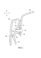
図1は、本発明の実施例に係る車両用ドアトリム構造(トリム構造100)を示す図である。図1(a)は、トリム構造100を、車両前方の左側上方から見た斜視図である。以下、図1その他の本願のすべての図面において、車両前後方向をそれぞれ矢印F(Forward)、B(Backward)、車幅方向の左右をそれぞれ矢印L(Leftward)、R(Rightward)、車両上下方向をそれぞれ矢印U(upward)、D(downward)で例示する。
FIG. 1 is a diagram showing a vehicle door trim structure (trim structure 100) according to an embodiment of the present invention. FIG. 1A is a perspective view of the
トリム構造100は、車両のドアの車内側に設けられるドアトリム102を中心に、スイッチベゼル104およびオーナメント106を備えている。スイッチベゼル104およびオーナメント106は、共に車室内を装飾する役割を担っている。
The
スイッチベゼル104は、ドアトリム102のアームレスト108の上面を構成するようにして、ドアトリム102にはめ込まれている。スイッチベゼル104の車両前側の部分には、パワーウィンドウ用等の所定のスイッチ類110が配置されている。また、スイッチベゼル104の車両後側の部分には、乗員が把持するプルハンドル112が配置されている。
The
オーナメント106は、スイッチベゼル104の車両後方側に隣接してドアトリム102にはめ込まれる。オーナメント106は、車室内を装飾する他、スイッチベゼル104と共にアームレスト108の上面を構成している。
The
図1(b)は、図1(a)のトリム構造100を車内側から正対して見た図である。上述しているように、スイッチベゼル104とオーナメント106は、アームレスト108を構成し、乗員からの荷重を受けやすい。そこで本実施例では、スイッチベゼル104およびオーナメント106をドアトリム102に簡単かつ十全な剛性で取り付けることを可能にし、各部品同士の境目である見切り線を維持して美観の維持および向上を図っている。
FIG. 1B is a view of the
図2は、図1(b)のドアトリム102を上方から見た図である。図2(a)では、ドアトリム102を、図1(b)のスイッチベゼル104およびオーナメント106を取り外した状態で示している。ドアトリム102には、スイッチベゼル104およびオーナメント106をはめ込む領域として、開口領域E1、E2が設けられている。スイッチベゼル104およびオーナメント106は、ドアトリム102に対して、所定のツメやボルト等の固着具を利用して組み付けられている。例えば、開口領域E1の周囲には、スイッチベゼル104のツメを挿しこむ挿込孔114が複数設けられている。
FIG. 2 is a view of the
図2(b)は、図2(a)のドアトリム102の領域Aの拡大図である。領域Aは、開口領域E1と開口領域E2との境界における車内側の部位である。本実施例では、スイッチベゼル104を組み付ける部位として、立壁部116および被嵌合部118が設けられている。立壁部116は車内側から車外側の斜め前方に向かって橋わたされた壁状の部位であり、被嵌合部118は立壁部116の車内側に設けられた車両上下方向に貫通した部位である。これら立壁部116および被嵌合部118には、後述するスイッチベゼル104の台座部122が組み付けられる。
Figure 2 (b) is an enlarged view of region A of the
図3は、図1(b)のスイッチベゼル104を車両後方の車外側下方から見た斜視図である。図3(a)は、スイッチベゼル104のプルハンドル112付近を示している。スイッチベゼル104のうち、車室内に露出する意匠面120の裏側には、前述したドアトリム102の立壁部116および被嵌合部118に結合する部位として、車両後方側の端に台座部122が設けられている。スイッチベゼル104は樹脂材料等から形成されていて、意匠面120や台座部122も一体成形されている。
FIG. 3 is a perspective view of the
図3(b)は、図3(a)の台座部122の拡大図である。台座部122は、意匠面120の裏側に、側壁部124および底壁部126をかけ渡して形成されている。そして、ドアトリム102と結合する部位として、側壁部124には結合孔128が設けられて、底壁部126にはツメ130が設けられている。
FIG. 3B is an enlarged view of the
図4は、図3(b)の台座部122を別方向から示した図である。図4(a)は、台座部122を車両後方から示している。スイッチベゼル104の意匠面120には、天面部132と、天面部132の車内側から下方に屈曲した側面部134が含まれている。台座部122は、天面部132の裏側から側壁部124が下方に延び、側面部134の裏側から底壁部126が車外側に延び、これら側壁部124と底壁部126とがつながった状態になっている。
FIG. 4 is a view showing the
台座部122は、全体的に見て、車両後方側が開放した箱型の形状になっている。側壁部124および底壁部126の車両後方側は箱の開口に該当していて、壁面が無く、開放された状態になっている。一方、側壁部124および底壁部126の車両前方側は箱の底に該当し、前壁部136によって閉じた状態になっている。
The
図4(b)は、図4(a)の台座部122を車外側から見た矢視B図である。前述したように、台座部122には、ツメ130が形成されている。ツメ130は、台座部122の底壁部126から下方に突出していて、ドアトリム102の被嵌合部118(図2(b)参照)に上方から挿し込まれる。ツメ130の内側には、上方に延びる自由端138が設けられている。ツメ130は、自由端138の弾性力を利用して、ドアトリム102の縁を把持することが可能になっている。
FIG. 4B is an arrow view B of the
結合孔128は、台座部122の車外側の側壁部124に設けられている。結合孔128は、ドアトリム102の立壁部116の孔部140に対して、スクリュー等の所定の固着具を利用して結合される。
The
図5は、図3(a)のドアトリム102に図4(b)の台座部122を組み付けた状態を例示した斜視図である。図5(a)は、台座部122等を車外側の下方から見て示している。スイッチベゼル104をドアトリム102に組み付ける場合、まず台座部122のツメ130を被嵌合部118に挿し込む。ツメ130の近傍には結合孔128が設けられていて、被嵌合部118の近傍の立壁部116には孔部140が設けられている。そのため、ツメ130を被嵌合部118に挿し込むだけで結合孔128と孔部140も位置合わせが行われる。結合孔128は、やや車両後方を向いた状態で形成されていて、ドアトリム102の立壁部116の孔部140にはめ込まれる。
FIG. 5 is a perspective view illustrating a state in which the
再び図4(b)を参照する。台座部122には、リブ142も設けられている。リブ142は、台座部122の側壁部124からツメ130にわたって、車両下方に延びるように形成されている。また、リブ142とは自由端138を挟んだ反対側にも、底壁部126からツメ130にわたってリブ144が延びている。これらリブ142、144は、ツメ130の剛性を高め、スイッチベゼル104をより高い剛性でドアトリム102に組み付けることを可能にする。
See FIG. 4B again. The
図2(b)に示すように、ドアトリム102の立壁部116の車両前方側の付け根付近には、車内側に規制部146が設けられている。図5(a)に示すように、規制部146は、リブ142に接触し、リブ142を介してスイッチベゼル104の動きを規制する。この構成によれば、規制部146の働きによって、スイッチベゼル104とドアトリム102との見切り線をより精度よく維持することが可能になる。
As shown in FIG. 2B, a
図5(b)は、図5(a)のドアトリム102の開口領域E2にオーナメント106をはめ込んだ様子である。オーナメント106の裏面のうち、ドアトリム102の立壁部116の近傍には、フランジ148が設けられている。フランジ148は、立壁部116に対し、台座部122とは反対側から接触する。そして、フランジ148、立壁部116および台座部122の結合孔128(図5(a)参照)は、固着具150によって共に結合される。
FIG. 5B shows the
図6は、図1(b)の車両用ドアトリム構造のC−C断面図である。図6に示すように、台座部122は箱型であって、意匠面120の裏側と共に側壁部124および底壁部126によって車幅方向の縦断面が閉じた閉断面を形成している。この構成によって、台座部122は高い剛性を発揮することが可能になっていて、ドアトリム102の立壁部116およびオーナメント106のフランジ148と高い剛性で結合することができる。
FIG. 6 is a cross-sectional view taken along the line CC of the vehicle door trim structure of FIG. 1 (b). As shown in FIG. 6, the
上記構成によれば、スイッチベゼル104をドアトリム102に高い剛性で組付け、スイッチベゼル104とドアトリム102との見切り線を精度よく形成し、維持することが可能になっている。加えて、台座部122にツメ130と結合孔128とを共に設けることで、ツメ130を挿すだけで結合孔128の位置合わせも行われるため、スイッチベゼル104のドアトリム102への組付作業もより簡単になっている。また、スイッチベゼル104は意匠面120と台座部122とを含めて一体に形成されていて、新たな部品の追加は行っていないため、構成が簡潔であって、重量やコストの増加を抑えることもできる。
According to the above configuration, the
オーナメント106においても、フランジ148を利用してドアトリム102の立壁部116およびスイッチベゼル104の結合孔128を共に結合することで、高い剛性で組み付けることが可能になっている。特に、オーナメント106は、スイッチベゼル104の意匠面120に隣接して組み付けられる。オーナメント106を高い剛性で組み付けることで、スイッチベゼル104の意匠面120との間の見切り線も精度良く形成し、維持することができる。
Also in the
(変形例)
図7は、図1等のスイッチベゼル104およびオーナメント106の変形例を示した図である。図7(a)は、スイッチベゼル200およびオーナメント202を車両上方から示した平面図である。スイッチベゼル200とオーナメント202は、アームレスト108の上方に、仮想線L1で示す車両上方から見て直線的な見切り線を形成している。
(Modification example)
FIG. 7 is a diagram showing a modified example of the
図7(b)は、図7(a)のスイッチベゼル200が有する結合孔204およびオーナメント202が有するフランジ206を車両上方から概略的に示した図である。結合孔204は、車両上方から見て、仮想線L1に対して垂直方向に延びる仮想線L2に沿って開けられている。この構成によれば、固着具150による支持剛性をスイッチベゼル200とオーナメント202との見切り線に対して均等に反映させ、見切り線の精度向上を図り、あわせて車室内の美観の向上に資することが可能になる。
FIG. 7B is a diagram schematically showing the
以上、添付図面を参照しながら本発明の好適な実施形態について説明したが、本発明は係る例に限定されないことは言うまでもない。当業者であれば、特許請求の範囲に記載された範疇内において、各種の変更例または修正例に想到し得ることは明らかであり、それらについても当然に本発明の技術的範囲に属するものと了解される。 Although preferred embodiments of the present invention have been described above with reference to the accompanying drawings, it goes without saying that the present invention is not limited to such examples. It is clear that a person skilled in the art can come up with various modifications or modifications within the scope of the claims, which naturally belong to the technical scope of the present invention. Understood.
本発明は、スイッチベゼルをドアトリムに簡単かつ十全な剛性で取り付けることが可能な車両用ドアトリム構造に利用することができる。 The present invention can be applied to a vehicle door trim structure in which a switch bezel can be easily and sufficiently rigidly attached to a door trim.
100…トリム構造、102…ドアトリム、104…スイッチベゼル、106…オーナメント、108…アームレスト、110…スイッチ類、112…プルハンドル、114…挿込孔、116…立壁部、118…被嵌合部、120…意匠面、122…台座部、124…側壁部、126…底壁部、128…結合孔、130…ツメ、132…天面部、134…側面部、136…前壁部、138…自由端、140…孔部、142…車両前側のリブ、144…車両後側のリブ、146…規制部、148…フランジ、150…固着具、200…変形例のスイッチベゼル、202…変形例のオーナメント、204…変形例の結合孔、206…変形例のフランジ、E1…スイッチベゼルがはめ込まれる開口領域、E2…オーナメントがはめ込まれる開口領域、L1…変形例のオーナメントとスイッチベゼルの見切り線を示す仮想線、L2…変形例の結合孔の開けられている方向を示す仮想線 100 ... Trim structure, 102 ... Door trim, 104 ... Switch bezel, 106 ... Ornament, 108 ... Armrest, 110 ... Switches, 112 ... Pull handle, 114 ... Insertion hole, 116 ... Standing wall part, 118 ... Fitted part, 120 ... Design surface, 122 ... Pedestal part, 124 ... Side wall part, 126 ... Bottom wall part, 128 ... Coupling hole, 130 ... Claw, 132 ... Top surface part, 134 ... Side part, 136 ... Front wall part, 138 ... Free end , 140 ... Hole, 142 ... Rib on the front side of the vehicle, 144 ... Rib on the rear side of the vehicle, 146 ... Regulatory part, 148 ... Flange, 150 ... Fixing tool, 200 ... Switch bezel of the modified example, 202 ... Ornament of the modified example, 204 ... Coupling hole of modified example, 206 ... Flange of modified example, E1 ... Opening area where switch bezel is fitted, E2 ... Opening area where ornament is fitted, L1 ... Virtual line showing parting line of ornament and switch bezel of modified example , L2 ... A virtual line indicating the direction in which the coupling hole of the modified example is formed.
Claims (3)
前記スイッチベゼルは、
車室内に露出する意匠面と、
前記意匠面の裏側に形成されていて、該意匠面の裏側と共に閉断面を形成する台座部と、
前記台座部から下方に突出して形成されていて前記ドアトリムに挿し込まれるツメと、
前記台座部の車幅方向の車外側に形成されていて所定の固着具によって前記ドアトリムに結合される結合孔と、
前記台座部から前記ツメにわたって形成されているリブと、
を有し、
前記ドアトリムは、
所定の箇所に上下方向に貫通した状態に設けられて前記ツメが挿し込まれる被嵌合部と、
前記被嵌合部の上側かつ車外側に壁状に設けられている立壁部と、
前記立壁部の車内側かつ前側に設けられて前記リブに接触して該リブを介して前記スイッチベゼルの動きを規制する規制部とを有することを特徴とする車両用ドアトリム構造。 In a vehicle door trim structure including a door trim provided inside the vehicle door and a switch bezel fitted in the door trim and arranged with predetermined switches.
The switch bezel is
The design surface exposed in the passenger compartment and
A pedestal portion formed on the back side of the design surface and forming a closed cross section together with the back side of the design surface.
A claw that is formed so as to project downward from the pedestal and is inserted into the door trim.
A coupling hole formed on the outside of the vehicle in the vehicle width direction of the pedestal portion and coupled to the door trim by a predetermined fastener ,
Ribs formed from the pedestal portion to the claws,
Have a,
The door trim
A fitted portion that is provided in a predetermined position so as to penetrate in the vertical direction and into which the claw is inserted, and a mated portion.
A wall-shaped vertical wall portion on the upper side of the fitted portion and on the outer side of the vehicle,
Vehicle door trim structure, which comprises organic and regulating portion in contact with the rib interior side and disposed in the front of the vertical wall portion to restrict the movement of the switch bezel via the ribs.
前記スイッチベゼルの意匠面に隣接して前記ドアトリムにはめ込まれるオーナメントを備え、
前記オーナメントの裏側には、前記固着具によって前記スイッチベゼルの結合孔および前記ドアトリムと結合可能なフランジが設けられていることを特徴とする請求項1に記載の車両用ドアトリム構造。 The door trim structure is further
With an ornament that fits into the door trim adjacent to the design surface of the switch bezel
On the back side of the ornament, the vehicle door trim structure according to claim 1, characterized in that coupling hole and the door trim and couplable flange of the switch bezel is provided by the fastener.
Priority Applications (4)
| Application Number | Priority Date | Filing Date | Title |
|---|---|---|---|
| JP2017153049A JP6953879B2 (en) | 2017-08-08 | 2017-08-08 | Vehicle door trim structure |
| CN201810719071.5A CN109383406B (en) | 2017-08-08 | 2018-07-03 | Vehicle door trim structure |
| FR1857069A FR3070028B1 (en) | 2017-08-08 | 2018-07-30 | VEHICLE DOOR TRIM STRUCTURE |
| DE102018118358.5A DE102018118358A1 (en) | 2017-08-08 | 2018-07-30 | VEHICLE DOOR PANEL STRUCTURE |
Applications Claiming Priority (1)
| Application Number | Priority Date | Filing Date | Title |
|---|---|---|---|
| JP2017153049A JP6953879B2 (en) | 2017-08-08 | 2017-08-08 | Vehicle door trim structure |
Publications (3)
| Publication Number | Publication Date |
|---|---|
| JP2019031184A JP2019031184A (en) | 2019-02-28 |
| JP2019031184A5 JP2019031184A5 (en) | 2020-08-20 |
| JP6953879B2 true JP6953879B2 (en) | 2021-10-27 |
Family
ID=65084604
Family Applications (1)
| Application Number | Title | Priority Date | Filing Date |
|---|---|---|---|
| JP2017153049A Active JP6953879B2 (en) | 2017-08-08 | 2017-08-08 | Vehicle door trim structure |
Country Status (4)
| Country | Link |
|---|---|
| JP (1) | JP6953879B2 (en) |
| CN (1) | CN109383406B (en) |
| DE (1) | DE102018118358A1 (en) |
| FR (1) | FR3070028B1 (en) |
Families Citing this family (3)
| Publication number | Priority date | Publication date | Assignee | Title |
|---|---|---|---|---|
| US11364859B2 (en) | 2019-12-20 | 2022-06-21 | Ford Global Technologies, Llc | Vehicle door assembly |
| KR102279701B1 (en) * | 2020-02-25 | 2021-07-20 | 주식회사 모베이스전자 | Steering wheel remote control switch |
| JP7289273B2 (en) * | 2020-03-09 | 2023-06-09 | 森六テクノロジー株式会社 | vehicle door trim |
Family Cites Families (8)
| Publication number | Priority date | Publication date | Assignee | Title |
|---|---|---|---|---|
| JP5045230B2 (en) * | 2007-05-15 | 2012-10-10 | スズキ株式会社 | Arm restore upper mounting structure for vehicle door trim |
| JP2008284958A (en) * | 2007-05-16 | 2008-11-27 | Kasai Kogyo Co Ltd | Door trim for automobile |
| JP2009029295A (en) * | 2007-07-27 | 2009-02-12 | Kasai Kogyo Co Ltd | Mounting structure of automobile interior component |
| JP5235126B2 (en) * | 2008-11-28 | 2013-07-10 | 河西工業株式会社 | Automotive interior parts |
| FR2959170B1 (en) * | 2010-04-23 | 2012-04-20 | Peugeot Citroen Automobiles Sa | SIDE DOOR OF A MOTOR VEHICLE EQUIPPED WITH A PROTECTIVE BAND AND A LATCH PROTECTED BY A REMOVABLE COVER. |
| JP6445431B2 (en) * | 2013-06-13 | 2018-12-26 | テイ・エス テック株式会社 | Vehicle door lining and its mounting structure |
| JP6207074B2 (en) * | 2013-12-19 | 2017-10-04 | ダイキョーニシカワ株式会社 | Vehicle door trim |
| US9505325B2 (en) * | 2014-12-11 | 2016-11-29 | Ford Global Technologies, Llc | Energy absorbing collapsible armrest with tunable stiffening feature |
-
2017
- 2017-08-08 JP JP2017153049A patent/JP6953879B2/en active Active
-
2018
- 2018-07-03 CN CN201810719071.5A patent/CN109383406B/en active Active
- 2018-07-30 DE DE102018118358.5A patent/DE102018118358A1/en active Pending
- 2018-07-30 FR FR1857069A patent/FR3070028B1/en active Active
Also Published As
| Publication number | Publication date |
|---|---|
| CN109383406A (en) | 2019-02-26 |
| CN109383406B (en) | 2022-01-11 |
| FR3070028B1 (en) | 2022-03-11 |
| JP2019031184A (en) | 2019-02-28 |
| FR3070028A1 (en) | 2019-02-15 |
| DE102018118358A1 (en) | 2019-02-14 |
Similar Documents
| Publication | Publication Date | Title |
|---|---|---|
| JP6953879B2 (en) | Vehicle door trim structure | |
| US7410206B2 (en) | Component parts joining structure | |
| JP2019064586A5 (en) | Mounting structure for interior parts to be installed on the vehicle interior side | |
| JP5168531B2 (en) | Door trim | |
| US10399513B2 (en) | Vehicle doors including door trim assemblies and vehicles including same | |
| WO2018002965A1 (en) | Vehicular door trim | |
| JP6852422B2 (en) | Front structure of the passenger compartment | |
| JP2008284900A (en) | Structure for mounting armrest upper part on door trim for vehicle | |
| JP5708337B2 (en) | Vehicle door trim | |
| JP5847244B1 (en) | Vehicle interior parts | |
| US8434810B2 (en) | Surrounding structure of storage compartment of instrument panel | |
| JP6111888B2 (en) | Door trim | |
| JP5949293B2 (en) | Interior materials for vehicles | |
| US10981479B2 (en) | Armrest assembly for a vehicle door and door assembly and vehicle including same | |
| JP6759702B2 (en) | Vehicle door trim | |
| JP2010023749A (en) | Vehicular instrument panel upper surface support structure | |
| JP2014218220A (en) | Door trim for vehicle | |
| JP4362843B2 (en) | Switch base mounting structure | |
| JP2014121942A (en) | Vehicle door trim | |
| JP5343717B2 (en) | Mounting structure for vehicle interior parts | |
| JP7234786B2 (en) | Mounting structure of vehicle exterior member | |
| JP7324404B2 (en) | pull handle | |
| JP4560467B2 (en) | Grip handle mounting structure for automobile seats | |
| JP4458343B2 (en) | Mounting structure of separate parts | |
| JP2021025327A (en) | Door handle structure |
Legal Events
| Date | Code | Title | Description |
|---|---|---|---|
| RD03 | Notification of appointment of power of attorney |
Free format text: JAPANESE INTERMEDIATE CODE: A7423 Effective date: 20180717 |
|
| A621 | Written request for application examination |
Free format text: JAPANESE INTERMEDIATE CODE: A621 Effective date: 20200624 |
|
| A521 | Written amendment |
Free format text: JAPANESE INTERMEDIATE CODE: A523 Effective date: 20200708 |
|
| A977 | Report on retrieval |
Free format text: JAPANESE INTERMEDIATE CODE: A971007 Effective date: 20210329 |
|
| A131 | Notification of reasons for refusal |
Free format text: JAPANESE INTERMEDIATE CODE: A131 Effective date: 20210511 |
|
| A521 | Written amendment |
Free format text: JAPANESE INTERMEDIATE CODE: A523 Effective date: 20210701 |
|
| TRDD | Decision of grant or rejection written | ||
| A01 | Written decision to grant a patent or to grant a registration (utility model) |
Free format text: JAPANESE INTERMEDIATE CODE: A01 Effective date: 20210831 |
|
| A61 | First payment of annual fees (during grant procedure) |
Free format text: JAPANESE INTERMEDIATE CODE: A61 Effective date: 20210913 |
|
| R151 | Written notification of patent or utility model registration |
Ref document number: 6953879 Country of ref document: JP Free format text: JAPANESE INTERMEDIATE CODE: R151 |