JP6909199B2 - Pachinko machine - Google Patents
Pachinko machine Download PDFInfo
- Publication number
- JP6909199B2 JP6909199B2 JP2018202634A JP2018202634A JP6909199B2 JP 6909199 B2 JP6909199 B2 JP 6909199B2 JP 2018202634 A JP2018202634 A JP 2018202634A JP 2018202634 A JP2018202634 A JP 2018202634A JP 6909199 B2 JP6909199 B2 JP 6909199B2
- Authority
- JP
- Japan
- Prior art keywords
- game
- state
- game ball
- small hit
- special
- Prior art date
- Legal status (The legal status is an assumption and is not a legal conclusion. Google has not performed a legal analysis and makes no representation as to the accuracy of the status listed.)
- Active
Links
Images


Description
本発明は、遊技が可能な遊技機に関する。 The present invention relates to a gaming machine capable of playing a game.
遊技機の一例であるパチンコ遊技機において、所定の流下経路を流下する遊技媒体が第1可変入賞装置と第2可変入賞装置とに進入可能なものにおいて、第1可変入賞装置の開放制御期間と第2可変入賞装置の開放制御期間の各々に対応して、ゲージを減少更新表示することにより発射促進報知を行うもの等があった(例えば、特許文献1参照)。 In a pachinko gaming machine, which is an example of a gaming machine, in a pachinko gaming machine in which a gaming medium flowing down a predetermined flow path can enter the first variable winning device and the second variable winning device, the opening control period of the first variable winning device and In response to each of the open control periods of the second variable winning device, there was a device that notifies the launch promotion by reducing and updating the gauge (see, for example, Patent Document 1).
上記特許文献1に記載の遊技機では、開放制御期間(所定期間)に対応した表示を行う演出の興趣が不十分であるという問題があった。
The gaming machine described in
本発明は、このような問題点に着目してなされたもので、興趣を向上させることができる遊技機を提供することを目的とする。 The present invention has been made by paying attention to such a problem, and an object of the present invention is to provide a gaming machine capable of improving the interest.
遊技を行うことが可能な遊技機であって、
遊技者にとって有利な内容に対応する有利演出を所定期間の経過後に実行可能であるとともに、前記所定期間の残り期間に対応した所定表示の更新動作を含む所定演出を実行可能な演出実行手段を備え、
前記演出実行手段は、
前記所定期間の経過後において前記所定表示の表示態様を特定態様としない第1パターンと、前記所定期間の経過後において新たな所定期間としての特定期間が設定されることに対応して前記所定表示の表示態様を特定態様とする第2パターンと、前記第1パターンとは異なるパターンであって前記所定表示の表示態様を特定態様としない第3パターンと、を含む複数種類のパターンのうちいずれかにて前記所定演出を実行可能であり、
前記第1パターンと前記第2パターンのいずれにおいても、前記所定期間が経過した時点から前記所定表示を共通の所定態様で表示することにより、前記特定期間が設定されることを示唆し、
前記第3パターンにおいては、前記所定期間が経過した時点において前記所定表示を前記所定態様とすることなく消去し、
前記第1パターンと前記第2パターンのいずれにおいても、前記所定期間が経過した時点において前記所定表示の表示態様を前記所定期間が残存しているような表示態様とすることが可能であり、
前記第1パターンと前記第2パターンと前記第3パターンのいずれにおいても、遊技者の動作促進演出を実行可能である、
ことを特徴としている。
手段1の遊技機は、
遊技を行うことが可能な遊技機(例えば、パチンコ遊技機1)であって、
遊技者にとって有利な内容に対応する有利演出(例えば、V入賞大当り演出/変形例1の大当り確定報知演出など)を所定期間(例えば、第2大入賞口702Bの開放期間/変形例1のプッシュボタン31Bの操作有効期間)の経過後に実行可能であるとともに、所定期間の残り期間に対応した所定表示(例えば、タイムゲージ画像Z4/変形例1のタイムゲージ画像Z34)の更新動作を含む所定演出(例えば、入賞促進演出/変形例1のボタン操作演出)を実行可能な演出実行手段(例えば、演出制御用CPU120)を備え、
前記演出実行手段は、
所定期間の経過後において所定表示の表示態様を特定態様としない第1パターン(例えば、演出パターンB/変形例1の演出パターンPT−2,PT−4)と、所定期間の経過後において所定期間が新たに設定されることに対応して所定表示の表示態様を特定態様とする第2パターン(例えば、演出パターンC/変形例1の演出パターンPT−3,PT−5,PT−6)と、を含む複数種類のパターンのうちいずれかにて所定演出を実行可能であり、
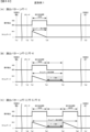
前記第1パターンと前記第2パターンのいずれにおいても、所定期間が経過した時点において所定表示の表示態様を共通の態様とすることにより、所定期間が新たに設定されることを示唆し(例えば、演出制御用CPU120が、入賞促進演出における小当り1、3、5、9に対応する演出パターンBと、小当り8、12に対応する演出パターンCでは、少なくとも第2大入賞口702Bの開放制御が終了(閉鎖)したタイミングTa3において、ゲージが残存しているような態様のタイムゲージ画像Z4が表示されることで、第2制御において第2大入賞口702Bの2回目の開放制御が行われる可能性を示唆する部分。図59〜図61参照/変形例1において、演出パターンPT−2,PT−4と演出パターンPT−3,PT−5,PT−6とは、少なくとも1回目の操作有効期間が終了するタイミングTa4からタイミングTa5まで、ゲージが残存しているような共通の態様のタイムゲージ画像Z34の表示が継続されることで、操作有効期間がもう1回設定される可能性が示唆される部分。図66〜図68参照)、
所定期間に対応して遊技者の動作を促す動作促進演出を実行可能である(例えば、演出制御用CPU120が、小当り遊技中において、第1制御における第2大入賞口702Bの開放及び第2制御における第2大入賞口702Bの開放に応じて、遊技者に第2大入賞口702Bを狙って遊技球を発射させる操作(動作)を促進する入賞促進演出を実行する部分/変形例1において、演出制御用CPU120が、プッシュボタン31Bの操作有効期間に応じて、遊技者にプッシュボタン31Bの操作を促すボタン操作演出を実行可能である部分)
ことを特徴としている。
この特徴によれば、遊技興趣を向上させることができる。
It is a gaming machine that can play games,
The advantageous effect corresponding to an advantageous content for the player as well as a feasible after a predetermined time period, with the effect execution unit capable of executing a predetermined effect including a predetermined display update operation corresponding to the remaining period of the predetermined time period ,
The effect executing means is
The predetermined display in response to the a first pattern not the specific embodiments said predetermined display of the display mode after the lapse of a predetermined period, a certain time period as a new predetermined period of time after elapse of the predetermined period is set Any one of a plurality of types of patterns including a second pattern having the display mode of the above-mentioned display mode as a specific mode, and a third pattern different from the first pattern but not having the display mode of the predetermined display as the specific mode. The above-mentioned predetermined effect can be executed at
In any of the second pattern, the first pattern also, by displaying the predetermined display from the time when the predetermined period has elapsed in a common predetermined manner, suggesting that the specific period is set,
In the third pattern, when the predetermined period elapses, the predetermined display is erased without the predetermined mode.
Wherein in both the first pattern and the second pattern, it is possible to the predetermined period a display mode of said predetermined display at the time when the predetermined period has elapsed the display mode, such as remaining,
In any of the first pattern, the second pattern, and the third pattern, the player's motion promotion effect can be executed.
It is characterized by that.
The gaming machine of
A gaming machine capable of playing a game (for example, a pachinko gaming machine 1).
An advantageous effect corresponding to the content advantageous to the player (for example, a V winning big hit effect / a large hit confirmation notification effect of the modified example 1) is set for a predetermined period (for example, an opening period of the second large winning
The effect executing means is
A first pattern (for example, effect pattern B / effect patterns PT-2 and PT-4 of the modified example 1) in which the display mode of the predetermined display is not a specific mode after the elapse of the predetermined period, and a predetermined period after the elapse of the predetermined period. With the second pattern (for example, effect pattern C / effect pattern PT-3, PT-5, PT-6 of the modified example 1) in which the display mode of the predetermined display is a specific mode in response to the newly set It is possible to execute a predetermined effect with any of a plurality of types of patterns including,
In both the first pattern and the second pattern, it is suggested that the predetermined period is newly set by making the display mode of the predetermined display a common mode when the predetermined period elapses (for example,). The
It is possible to execute an operation promotion effect that encourages the player's operation in response to a predetermined period (for example, the
It is characterized by that.
According to this feature, it is possible to improve the game entertainment.
手段2の遊技機は、手段1に記載の遊技機であって、
遊技媒体(例えば、遊技球P)が進入可能な進入可能状態(例えば、開放状態)に変化可能な可変手段(例えば、第2特別可変入賞球装置7B)を備え、
前記可変手段に進入した遊技媒体が通過可能な所定領域(例えば、第2大入賞口702B)と、
前記所定領域を通過した遊技媒体が通過可能な特定領域(例えば、V入賞口283)とが設けられ、
遊技媒体が前記特定領域を通過したことに基づいて遊技者にとって有利な価値を付与可能であり(例えば、V入賞球保持部272が回転してV入賞口283に対応する位置に到達すると、遊技球P1がV入賞口283に進入し、第3カウントスイッチ24Bにより検出されることでV入賞が発生する)、
所定期間は、前記可変手段が前記進入可能状態に制御される期間(例えば、第2大入賞口702Bの開放期間)に対応する期間である
ことを特徴としている。
この特徴によれば、興趣を向上させることができる。
The gaming machine of the
A variable means (for example, a second special variable winning
A predetermined area through which the game medium that has entered the variable means can pass (for example, the second large winning opening 702B) and
A specific area (for example, V winning opening 283) through which the game medium that has passed through the predetermined area can pass is provided.
It is possible to give an advantageous value to the player based on the fact that the game medium has passed through the specific area (for example, when the V winning
The predetermined period is characterized in that it is a period corresponding to a period in which the variable means is controlled to be in the accessible state (for example, an opening period of the second large winning
According to this feature, it is possible to improve the interest.
手段3の遊技機は、手段1または2に記載の遊技機であって、
前記演出実行手段は、前記第1パターンと前記第2パターンのいずれにおいても、所定期間が経過した時点において所定表示の表示態様を所定期間が残存しているような表示態様とすることが可能である(例えば、演出制御用CPU120が、演出パターンBと演出パターンCにおいて、少なくとも第2大入賞口702Bの開放期間が終了したタイミングTa3において、ゲージが残存しているような共通の態様のタイムゲージ画像Z4を表示する部分。図63参照/変形例1において、演出制御用CPU120が、2回目の操作有効期間が設定されない演出パターンPT−2,PT−4が実行される場合でも、少なくとも1回目の操作有効期間が終了したタイミングTa4においては、タイムゲージ画像Z34は、演出パターンPT−3,PT−5,PT−6におけるタイムゲージ画像Z34と共通の態様で表示する部分。図67(B)参照)
ことを特徴としている。
この特徴によれば、興趣を向上させることができる。
The gaming machine of
In both the first pattern and the second pattern, the effect executing means can change the display mode of the predetermined display to a display mode in which the predetermined period remains after the predetermined period has elapsed. (For example, the
It is characterized by that.
According to this feature, it is possible to improve the interest.
手段4の遊技機は、手段1〜3のいずれかに記載の遊技機であって、
所定期間は、遊技者の動作を検出可能な動作検出期間(例えば、変形例1におけるプッシュボタン31Bの操作有効期間)であり、
特定期間(例えば、可変表示期間など)のうちに動作検出期間を複数回設定可能である(例えば、変形例1において、演出制御用CPU120が、ボタン操作演出において操作有効期間が2回設定される演出パターンPT−3,PT−5,PT−6を実行可能な部分)
ことを特徴としている。
この特徴によれば、興趣を向上させることができる。
The gaming machine of
The predetermined period is a motion detection period in which the player's motion can be detected (for example, the operation valid period of the
The operation detection period can be set a plurality of times within a specific period (for example, a variable display period) (for example, in the
It is characterized by that.
According to this feature, it is possible to improve the interest.
手段5の遊技機は、手段1〜4のいずれかに記載の遊技機であって、
前記演出実行手段は、
前記第1パターン及び前記第2パターンにおいて、所定期間が経過した後も所定表示を継続して表示し(例えば、演出制御用CPU120が、演出パターンBと演出パターンCにおいて、第2大入賞口702Bの開放制御が終了(閉鎖)したタイミングTa3からV入賞判定が行われるタイミングTa4まで、ゲージが残存しているような態様のタイムゲージ画像Z4の表示を継続する部分/変形例1において、演出制御用CPU120が、演出パターンPT−2,PT−4と演出パターンPT−3,PT−5,PT−6において、1回目の操作有効期間が終了するタイミングTa4からタイミングTa5まで、ゲージが残存しているような共通の態様のタイムゲージ画像Z34の表示を継続する部分)、
所定期間が経過した時点または所定期間が経過する前に所定表示を消去する第3パターンにて所定演出を実行可能である(例えば、演出制御用CPU120が、演出パターンAにおいて、第2大入賞口702Bの開放制御が終了(閉鎖)したタイミングTa3にてタイムゲージ画像Z4を消去する部分。図60、図61参照/変形例1において、演出制御用CPU120が、演出パターンPT−1において、1回目の操作有効期間が終了したタイミングTa4にてタイムゲージ画像Z34を消去する部分。図68参照)
ことを特徴としている。
この特徴によれば、興趣を向上させることができる。
The gaming machine of
The effect executing means is
In the first pattern and the second pattern, the predetermined display is continuously displayed even after the predetermined period has elapsed (for example, the
The predetermined effect can be executed in the third pattern in which the predetermined display is erased when the predetermined period elapses or before the predetermined period elapses (for example, the
It is characterized by that.
According to this feature, it is possible to improve the interest.
手段6の遊技機は、手段1〜5のいずれかに記載の遊技機であって、
前記演出実行手段は、前記第2パターンにて所定演出を実行するか否かにかかわらず、所定期間が経過した後も所定表示を継続して表示する(例えば、所定期間の経過後に新たに所定期間が設定されない演出パターンAや変形例1の演出パターンPT−1においても、つまり、第2パターンにて所定演出が実行されるか否かにかかわらず、所定期間の経過後においても所定表示を継続して表示する部分。変形例)
ことを特徴としている。
この特徴によれば、興趣を向上させることができる。
The gaming machine of
The effect executing means continuously displays the predetermined display even after the predetermined period has elapsed, regardless of whether or not the predetermined effect is executed in the second pattern (for example, newly determined after the predetermined period has elapsed). Even in the effect pattern A in which the period is not set and the effect pattern PT-1 of the modification example 1, that is, regardless of whether or not the predetermined effect is executed in the second pattern, the predetermined display is displayed even after the elapse of the predetermined period. The part to be displayed continuously. Modification example)
It is characterized by that.
According to this feature, it is possible to improve the interest.
尚、本発明は、本発明の請求項に記載された発明特定事項のみを有するものであっても良いし、本発明の請求項に記載された発明特定事項とともに該発明特定事項以外の構成を有するものであっても良い。 In addition, the present invention may have only the invention-specific matters described in the claims of the present invention, or may have a configuration other than the invention-specific matters together with the invention-specific matters described in the claims of the present invention. It may have.
(パチンコ遊技機1の構成等)
まず、遊技機の一例であるパチンコ遊技機1の全体の構成について説明する。図1は、パチンコ遊技機1を正面からみた正面図である。図2は、パチンコ遊技機1の回路構成例を示すブロック図である。尚、以下の説明において、図1の手前側をパチンコ遊技機1の前方(前面、正面)側、奥側を後方(背面)側として説明する。尚、本実施の形態におけるパチンコ遊技機1の前面とは、遊技者側からパチンコ遊技機1を見たときに該遊技者と対向する対向面である。尚、本実施の形態におけるフローチャートの各ステップの説明において、例えば「ステップS1」と記載する箇所を「S1」と略記する場合がある。
(Configuration of
First, the overall configuration of the
図1は、本実施の形態におけるパチンコ遊技機1の正面図であり、主要部材の配置レイアウトを示す。パチンコ遊技機1(以下、遊技機と略記する場合がある)は、大別して、遊技盤面を構成する遊技盤2(ゲージ盤)と、遊技盤2を支持固定する遊技機用枠3(台枠)とから構成されている。遊技盤2には、ガイドレール2bによって囲まれた、ほぼ円形状の遊技領域Yが形成されている。この遊技領域Yには、遊技媒体としての遊技球が、所定の打球発射装置から発射されて打ち込まれる。また、遊技機用枠3には、ガラス窓50aを有するガラス扉枠50が左側辺を中心として回動可能に設けられ、該ガラス扉枠50により遊技領域Yを開閉できるようになっており、ガラス扉枠50を閉鎖したときにガラス窓50aを通して遊技領域Yを透視できるようになっている。
FIG. 1 is a front view of the
遊技盤2の所定位置(図1に示す例では、遊技領域Yの下方)には、複数種類の特別識別情報としての特別図柄(特図ともいう)の可変表示(特図ゲームともいう)を行う第1特別図柄表示装置4A及び第2特別図柄表示装置4Bが設けられている。これらは、それぞれ、7セグメントのLEDなどからなる。特別図柄は、「0」〜「9」を示す数字や「−」などの点灯パターンなどにより表される。特別図柄には、LEDを全て消灯したパターンが含まれてもよい。
At a predetermined position of the game board 2 (in the example shown in FIG. 1, below the game area Y), a variable display (also referred to as a special figure game) of a special symbol (also referred to as a special figure) as a plurality of types of special identification information is displayed. The first special
尚、特別図柄の「可変表示」とは、例えば、複数種類の特別図柄を変動可能に表示することである(後述の他の図柄についても同じ)。変動としては、複数の図柄の更新表示、複数の図柄のスクロール表示、1以上の図柄の変形、1以上の図柄の拡大/縮小などがある。特別図柄や後述の普通図柄の変動では、複数種類の特別図柄又は普通図柄が更新表示される。後述の飾り図柄の変動では、複数種類の飾り図柄がスクロール表示又は更新表示されたり、1以上の飾り図柄が変形や拡大/縮小されたりする。尚、変動には、ある図柄を点滅表示する態様も含まれる。可変表示の最後には、表示結果として所定の特別図柄が停止表示(導出又は導出表示などともいう)される(後述の他の図柄の可変表示についても同じ)。尚、可変表示を変動表示、変動と表現する場合がある。 The "variable display" of the special symbol is, for example, to display a plurality of types of special symbols in a variable manner (the same applies to other symbols described later). Fluctuations include update display of a plurality of symbols, scroll display of a plurality of symbols, deformation of one or more symbols, enlargement / reduction of one or more symbols, and the like. When the special symbol or the ordinary symbol described later is changed, a plurality of types of special symbols or ordinary symbols are updated and displayed. In the variation of the decorative symbol described later, a plurality of types of decorative symbols are scrolled or updated, and one or more decorative symbols are deformed or enlarged / reduced. The variation also includes a mode in which a certain symbol is blinked and displayed. At the end of the variable display, a predetermined special symbol is stopped (also referred to as derivation or derivation display) as a display result (the same applies to the variable display of other symbols described later). The variable display may be expressed as a variable display or a variable display.
尚、第1特別図柄表示装置4Aにおいて可変表示される特別図柄を「第1特図」ともいい、第2特別図柄表示装置4Bにおいて可変表示される特別図柄を「第2特図」ともいう。また、第1特図を用いた特図ゲームを「第1特図ゲーム」といい、第2特図を用いた特図ゲームを「第2特図ゲーム」ともいう。尚、特別図柄の可変表示を行う特別図柄表示装置は1種類であってもよい。
The special symbol variably displayed on the first special
遊技盤2における遊技領域Yの中央付近には画像表示装置5が設けられている。画像表示装置5は、例えばLCD(液晶表示装置)や有機EL(Electro Luminescence)等から構成され、各種の演出画像を表示する。画像表示装置5は、プロジェクタ及びスクリーンから構成されていてもよい。画像表示装置5には、各種の演出画像が表示される。
An
例えば、画像表示装置5の画面上では、第1特図ゲームや第2特図ゲームと同期して、特別図柄とは異なる複数種類の装飾識別情報としての飾り図柄(数字などを示す図柄など)の可変表示が行われる。ここでは、第1特図ゲーム又は第2特図ゲームに同期して、「左」、「中」、「右」の各飾り図柄表示エリア5L、5C、5Rにおいて飾り図柄が可変表示(例えば上下方向のスクロール表示や更新表示)される。尚、同期して実行される特図ゲーム及び飾り図柄の可変表示を総称して単に可変表示ともいう。
For example, on the screen of the
画像表示装置5の画面上には、実行が保留されている可変表示に対応する保留表示や、実行中の可変表示に対応するアクティブ表示を表示するための表示エリアが設けられていてもよい。保留表示及びアクティブ表示を総称して可変表示に対応する可変表示対応表示ともいう。
On the screen of the
保留されている可変表示の数は保留記憶数ともいう。第1特図ゲームに対応する保留記憶数を第1保留記憶数、第2特図ゲームに対応する保留記憶数を第2保留記憶数ともいう。また、第1保留記憶数と第2保留記憶数との合計を合計保留記憶数ともいう。 The number of variable displays on hold is also called the number of stored items on hold. The number of reserved storage corresponding to the first special figure game is also referred to as the first reserved storage number, and the number of reserved storage corresponding to the second special figure game is also referred to as the second reserved storage number. Further, the total of the first reserved storage number and the second reserved storage number is also referred to as a total reserved storage number.
また、遊技盤2の所定位置には、複数のLEDを含んで構成された第1保留表示器25Aと第2保留表示器25Bとが設けられ、第1保留表示器25Aは、LEDの点灯個数によって、第1保留記憶数を表示し、第2保留表示器25Bは、LEDの点灯個数によって、第2保留記憶数を表示する。
Further, at a predetermined position of the
画像表示装置5の下方には、入賞球装置6Aが設けられ、画像表示装置5の左側方には、可変入賞球装置6Bが設けられている。
A winning
入賞球装置6Aは、例えば所定の球受部材によって常に遊技球が進入可能な一定の開放状態に保たれる第1始動入賞口を形成する。第1始動入賞口に遊技球が進入したときには、所定個(例えば3個)の賞球が払い出されるとともに、第1特図ゲームが開始され得る。
The winning
可変入賞球装置6B(普通電動役物)は、第1ソレノイド81によって進入困難状態と進入可能状態とに変化する第2始動入賞口(図示略)を形成する。可変入賞球装置6Bは、例えば、前後方向に移動可能な可変板(図示略)を有し、第1ソレノイド81がオフ状態であるときに可変板が退避位置となることにより、当該可変板が遊技領域Y側から退避して、第2始動入賞口に遊技球が進入しない進入困難状態になる(第2始動入賞口が進入困難状態になるともいう。)。その一方で、可変入賞球装置6Bは、第1ソレノイド81がオン状態であるときに可変板が遊技領域Y側に進出する進出位置となることにより、第2始動入賞口に遊技球が進入可能(進入容易)な進入可能状態になる(第2始動入賞口が進入可能状態になるともいう。)。第2始動入賞口に遊技球が進入したときには、所定個(例えば3個)の賞球が払い出されるとともに、第2特図ゲームが開始され得る。尚、可変入賞球装置6Bは、進入困難状態と進入可能状態とに変化するものであればよく、例えば、電動チューリップ型役物であってもよい。尚、可変入賞球装置6Bの詳細な構造については後述する。
The variable winning
遊技盤2の所定位置(図1に示す例では、遊技領域Yの左下方3箇所)には、所定の球受部材によって常に一定の開放状態に保たれる一般入賞口10が設けられる。この場合には、一般入賞口10のいずれかに進入したときには、所定個数(例えば10個)の遊技球が賞球として払い出される。
At a predetermined position of the game board 2 (in the example shown in FIG. 1, three locations on the lower left side of the game area Y), a general winning
入賞球装置6Aの下方には、第1大入賞口701Bを有する第1特別可変入賞球装置7Aが設けられている。第1特別可変入賞球装置7Aは、第2ソレノイド82(図2参照)によって開閉駆動される第1大入賞口扉701Aを備え、その第1大入賞口扉701Aによって進入可能状態(開放状態)と進入困難状態(閉鎖状態)とに変化する第1大入賞口701Bを形成する。
Below the winning
一例として、第1特別可変入賞球装置7Aでは、第1大入賞口扉701A用(特別電動役物用)の第2ソレノイド82がオフ状態であるときに第1大入賞口扉701Aが第1大入賞口701Bを進入困難状態(閉鎖状態)として、遊技球が第1大入賞口701Bに進入(通過)できなくなる。その一方で、第1特別可変入賞球装置7Aでは、第1大入賞口扉701A用の第1ソレノイド82がオン状態であるときに第1大入賞口扉701Aが第1大入賞口701Bを進入可能状態(開放状態)として、遊技球が第1大入賞口701Bに進入しやすくなる。
As an example, in the first special variable winning
第1大入賞口701Bを通過(進入)した遊技球は、例えば図2に示す第1カウントスイッチ23によって検出される。第1カウントスイッチ23によって遊技球が検出されたことに基づき、所定個数(例えば15個)の遊技球が賞球として払い出される。こうして、第1特別可変入賞球装置7Aにおいて進入可能状態(開放状態)となった第1大入賞口701Bを遊技球が通過(進入)したときには、例えば、始動入賞口といった、他の入賞口を遊技球が通過(進入)したときよりも多くの賞球が払い出される。従って、第1特別可変入賞球装置7Aにおいて第1大入賞口701Bが進入可能状態(開放状態)となれば、その第1大入賞口701Bに遊技球が進入可能となり、遊技者にとって有利となる。その一方で、第1特別可変入賞球装置7Aにおいて第1大入賞口701Bが進入困難状態となれば、第1大入賞口701Bに遊技球を通過(進入)させて賞球を得ることが不可能または困難になり、遊技者にとって不利となる。
The game ball that has passed (entered) the first winning
遊技盤2における遊技領域Yの中央部から右側部にかけて第2特別可変入賞球装置7Bが設けられている。この第2特別可変入賞球装置7Bは、遊技者が画像表示装置5を視認可能なように枠状に形成されている。また、第2特別可変入賞球装置7Bは、上端部に第2大入賞口702B用となる第3ソレノイド83によって開閉駆動される第2大入賞口扉702Aを備え、その第2大入賞口扉702Aによって進入可能状態(開放状態)と進入困難状態(閉鎖状態)とに変化する第2大入賞口702Bを形成する。
A second special variable winning
一例として、第2特別可変入賞球装置7Bでは、第2大入賞口扉702A用の第3ソレノイド83がオフ状態であるときに第2大入賞口扉702Aが第2大入賞口702Bを閉鎖状態として、遊技球が第2大入賞口702Bを通過(進入)できなくする。その一方で、第2特別可変入賞球装置7Bでは、第2大入賞口扉702A用の第3ソレノイド83がオン状態であるときに第2大入賞口扉702Aが第2大入賞口702Bを開放状態として、遊技球が第2大入賞口702Bを通過(進入)しやすくする。
As an example, in the second special variable winning
第2大入賞口702Bを通過(進入)した遊技球は、例えば図2に示す第2カウントスイッチ24Aによって検出される。第2カウントスイッチ24Aによって遊技球が検出されたことに基づき、所定個数(例えば15個)の遊技球が賞球として払い出される。こうして、第2特別可変入賞球装置7Bにおいて進入可能状態(開放状態)となった第2大入賞口702Bを遊技球が通過(進入)したときには、例えば、始動入賞口といった、他の入賞口を遊技球が通過(進入)したときよりも多くの賞球が払い出される。従って、第2特別可変入賞球装置7Bにおいて第2大入賞口702Bが進入可能状態(開放状態)となれば、その第2大入賞口702Bに遊技球が進入可能となり、遊技者にとって有利となる。その一方で、第2特別可変入賞球装置7Bにおいて第2大入賞口702Bが閉鎖状態となれば、第2大入賞口702Bに遊技球を通過(進入)させて賞球を得ることが不可能または困難になり、遊技者にとって不利となる。
The game ball that has passed (entered) the second winning
また、詳細は後述するが、第2特別可変入賞球装置7B内には、第3カウントスイッチ24Bと第4カウントスイッチ24Cと第5カウントスイッチ24Dが設けられている。本実施の形態では、後述する小当りが発生したことに基づいて小当り遊技状態に制御されることにより、第2特別可変入賞球装置7Bが進入困難状態から進入可能状態に変化し、該小当り遊技状態において第2大入賞口702Bに進入した遊技球が後述するV入賞口283(図13参照)に進入して第3カウントスイッチ24Bにより検出されることによりV入賞が発生することで、遊技者にとって有利な大当り遊技状態に制御される。
Further, as will be described in detail later, a
一般入賞口10を含む各入賞口に遊技球が進入することを「入賞」ともいう。特に、始動口(第1始動入賞口、第2始動入賞口)への入賞を始動入賞ともいう。
The entry of a game ball into each winning opening including the general winning
遊技盤2の所定位置(図1に示す例では、遊技領域Yの下方)には、普通図柄表示器20が設けられている。一例として、普通図柄表示器20は、7セグメントのLEDなどからなり、特別図柄とは異なる複数種類の普通識別情報としての普通図柄の可変表示を行う。普通図柄は、「0」〜「9」を示す数字や「−」などの点灯パターンなどにより表される。普通図柄には、LEDを全て消灯したパターンが含まれてもよい。このような普通図柄の可変表示は、普図ゲームともいう。
A
可変入賞球装置6Bの上部には、遊技球が通過可能な通過ゲート41が設けられている。遊技球が通過ゲート41を通過したことに基づき、普図ゲームが実行される。
A passing
尚、本実施の形態では、普図ゲームの数である普図保留記憶数を記憶するための普図保留表示器は設けられていないが、普図保留表示器を設けて普図保留記憶数を記憶可能としてもよい。 In the present embodiment, the normal figure hold display for storing the number of normal figure hold storages, which is the number of normal figure games, is not provided, but the normal figure hold display is provided and the number of normal figure hold storages is provided. May be memorable.
遊技盤2の表面には、上記の構成以外にも、遊技球の流下方向や速度を変化させる風車及び多数の障害釘が設けられている。遊技領域Yの最下方には、いずれの入賞口にも進入しなかった遊技球が取り込まれるアウト口が設けられている。
In addition to the above configuration, the surface of the
遊技盤2の所定位置には、後述する可動通路体400や演出可動体500が設けられている。
A
遊技機用枠3の左右上部位置には、効果音等を再生出力するためのスピーカ8L、8Rが設けられており、さらに遊技領域Y周辺部には、遊技効果用の遊技効果ランプ9が設けられている。遊技効果ランプ9は、LEDを含んで構成されている。
遊技機用枠3の右下部位置には、遊技球を打球発射装置により遊技領域Yに向けて発射するために遊技者等によって操作される打球操作ハンドル(操作ノブ)30が設けられている。
At the lower right position of the
遊技領域Yの下方における遊技機用枠3の所定位置には、賞球として払い出された遊技球や所定の球貸機により貸し出された遊技球を、打球発射装置へと供給可能に保持(貯留)する打球供給皿(上皿)が設けられている。上皿の下方には、上皿満タン時に賞球が払い出される打球供給皿(下皿)が設けられている。
At a predetermined position of the
遊技領域Yの下方における遊技機用枠3の所定位置には、遊技者が把持して傾倒操作が可能なスティックコントローラ31Aが取付けられている。スティックコントローラ31Aには、遊技者が押下操作可能なトリガボタンが設けられている。スティックコントローラ31Aに対する操作は、コントローラセンサユニット35A(図2参照)により検出される。
A
遊技領域Yの下方における遊技機用枠3の所定位置には、遊技者が押下操作などにより所定の指示操作を可能なプッシュボタン31Bが設けられている。プッシュボタン31Bに対する操作は、プッシュセンサ35B(図2参照)により検出される。
A
パチンコ遊技機1では、遊技者の動作(操作等)を検出する検出手段として、スティックコントローラ31Aやプッシュボタン31Bが設けられるが、これら以外の検出手段が設けられていてもよい。
The
(第2特別可変入賞球装置7B)
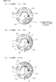
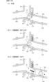
次に、図3〜図14に基づいて、第2特別可変入賞球装置7Bの詳細について説明する。図3は、第2特別可変入賞球装置を示す概略正面図である。図4は、遊技盤を斜め前から見た状態を示す斜視図である。図5は、遊技盤を斜め後ろから見た状態を示す斜視図である。図6は、(A)は第2大入賞口扉が閉鎖位置にある状態、(B)は第2大入賞口扉が開放位置にある状態における第2大入賞口を示す断面図である。図7は、(A)は第1貯留板が貯留位置にある状態、(B)は第1貯留板が解除位置にある状態における第1貯留機構を示す断面図である。図8は、(A)は振分部材の第1回動状態、(B)は振分部材の第2回動状態における第2貯留機構を示す断面図、(C)は(A)のA−A断面図である。図9は、(A)は第2貯留部に1個の遊技球が貯留された状態、(B)は後続の遊技球が排出経路へ誘導されている状態、(C)は貯留された遊技球を振分部材で保持した状態、(D)は振分部材により遊技球を回転体に向けて放出した状態における第2貯留部を示す概略図である。図10は、(A)は第2貯留部に2個の遊技球が貯留された状態、(B)は後続の遊技球が排出経路へ誘導されている状態、(C)は貯留された先頭の遊技球を振分部材で保持した状態、(D)は振分部材により先頭の遊技球を回転体に向けて放出した状態、(E)は貯留された後続の遊技球を振分部材で保持した状態、(F)は振分部材により後続の遊技球を回転体に向けて放出した状態における第2貯留部を示す概略図である。図11は、第2特別可変入賞球装置の下部の構造を示す分解斜視図である。図12は、(A)は開閉板が開放位置にある状態、(B)は開閉板が閉鎖位置にある状態、(C)(D)は回転体を示す平面断面図である。図13は、図12(C)におけるB−B断面図である。図14は、(A)は図12(C)におけるC−C断面図、(B)は図12(D)におけるC’−C’断面図である。尚、以下においては、遊技球を遊技球Pや遊技球P1,P2・・などと呼ぶことがある。
(2nd special variable winning
Next, the details of the second special variable winning
図3〜図5に示すように、第2特別可変入賞球装置7Bは、前述したように、画像表示装置5の上方である遊技領域Yの上部に設けられた第2大入賞口702Bから進入した遊技球を下方に誘導する第1誘導経路201と、第1誘導経路201にて誘導された遊技球を後述するV入賞口283(図12参照)に進入可能に誘導する第2誘導経路202A,202Bと、第1誘導経路201にて誘導された遊技球を後述するV入賞口283に進入不可能に誘導する第3誘導経路203A,203Bと、第2誘導経路202Aへ進入可能に誘導された遊技球を貯留可能な第1貯留機構204と、第3誘導経路203Aにより誘導された遊技球を貯留可能な第2貯留機構205と、第2誘導経路202A,202Bにより誘導された遊技球をV入賞口283に進入可能に保持するV入賞球保持部272(図12(C)(D)参照)及び第2誘導経路202A,202Bまたは第3誘導経路203A,203Bにより誘導された遊技球をV入賞口283に進入不可能に保持するハズレ球保持部273A〜273E(図12(C)(D)参照)を有する回転体208と、画像表示装置5の下方において回転体208を回転可能に支持する支持部材209と、第3誘導経路203Aへ誘導された遊技球の一部を遊技盤2の背面側へ誘導した後にパチンコ遊技機1外へ排出するための排出経路210と、を主に有している。
As shown in FIGS. 3 to 5, as described above, the second special variable winning
尚、これら第1誘導経路201、第2誘導経路202A,202B、第3誘導経路203A,203B、第1貯留機構204及び第2貯留機構205は、合成樹脂材からなる通路形成部材により全て筒状に形成されており、第2大入賞口702Bから進入した遊技球は自然流下により流下するようになっている。また、第1誘導経路201、第2誘導経路202A,202B、第3誘導経路203A,203Bの少なくとも前面側は透光性を有する合成樹脂材により形成されており、内部を流下する遊技球を遊技者から透視可能とされている。
The first
また、第3誘導経路203A,203Bは、遊技盤2の背面側に設けられる画像表示装置5の左前側に重畳する位置(画像表示装置5の表示領域(飾り図柄表示エリア5L,5C,5Rや保留記憶表示エリア)には重畳しない位置)に配置されており、該画像表示装置5の表示領域を遊技者が視認できるようになっている。
Further, the
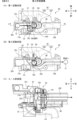
図6に示すように、第2大入賞口702Bは、遊技盤2の遊技盤面の前方に上向きに開口するように設けられる平面視横長長方形状の入賞口とされている。第2大入賞口扉702Aは、第3ソレノイド83のプランジャ83Aとリンク部材220を介して連結されており、第3ソレノイド83がオフ状態であるときに第2大入賞口702Bを閉鎖する閉鎖位置(図6(A)参照)と、第3ソレノイド83がオン状態であるときに遊技盤2側に退避して第2大入賞口702Bを開放する開放位置(図6(B)参照)と、の間で前後方向にスライド移動可能に設けられている。
As shown in FIG. 6, the second large winning
また、第2大入賞口扉702Aは、図3に示すように右端から左端に向けて漸次下方に傾斜するように設けられ、閉鎖位置において、第2大入賞口扉702Aの右側に設けられた壁部Hにより誘導される遊技球を左側へ誘導するように設けられている。尚、本実施の形態では、図示しない発射装置から発射され遊技領域Yの上部に進入した遊技球のうち、壁部Hに衝突した遊技球はほぼ第2大入賞口702Bへ向けて誘導される。そして、第2大入賞口702Bが進入困難状態(閉鎖状態)であるときは第2大入賞口扉702A上を流下して第2大入賞口702Bの左側へ誘導され、第2大入賞口702Bが進入可能状態(開放状態)であるときは第2大入賞口702Bに進入可能となる。
Further, as shown in FIG. 3, the second prize-winning
また、本実施の形態では、第2大入賞口扉702Aは、第2大入賞口702Bを進入困難状態とする閉鎖位置にあるとき、該第2大入賞口扉702Aの上面を複数の遊技球が左側に向けて流下可能な長さを有しているため、進入可能状態に変化したときに複数の遊技球が一斉に入賞することがある。
Further, in the present embodiment, when the second prize-winning
尚、本実施の形態では、第2大入賞口702Bが進入困難状態であるとき、第2大入賞口扉702Aの上面を複数の遊技球が左側に向けて流下する形態を例示したが、本発明はこれに限定されるものではなく、第2大入賞口扉702Aの上面を遊技球が通過するのに要する期間が長くなるようにするための遅延手段(例えば、第2大入賞口702Bの上方の前後壁に遊技球の流下方向に向けて交互に設けた複数の接触部など)を設けることで、遊技球を前後に蛇行しながら左側に向けて流下させて流下速度を遅くする。このようにすることで、第2大入賞口扉702Aの上面を通過する際に多数の遊技球が滞留しやすくなるため、進入可能状態に変化したときに多数の遊技球を入賞させることが可能となる。
In the present embodiment, when the second big winning
(第1貯留機構204)
図7に示すように、第2大入賞口702Bに進入した遊技球は、第1誘導経路201を流下する途中で第2カウントスイッチ24Aにて検出された後、第2誘導経路202Aと第3誘導経路203Aとの分岐部221に到達する。第2誘導経路202Aにおける分岐部221の近傍位置には、第1貯留機構204が設けられており、第2誘導経路202Aへ進入した遊技球を1個だけ貯留できるようになっている。
(1st storage mechanism 204)
As shown in FIG. 7, the game ball that has entered the second large winning
第1貯留機構204は、第2誘導経路202Aへ進入した遊技球P1(1個目の遊技球)の流下を規制して貯留することが可能な第1貯留板222と、第1貯留板222を駆動させる第4ソレノイド84と、を有する。第1貯留板222は、第4ソレノイド84のプランジャ84Aとリンク部材223を介して連結されており、第4ソレノイド84がオフ状態であるときに第2誘導経路202Aへ突出して遊技球の流下を規制して該第2誘導経路202Aに貯留する貯留位置(図7(A)参照)と、第4ソレノイド84がオン状態であるときに第2誘導経路202Aの上方に退避して遊技球の流下を許容して貯留を解除する解除位置(図7(B)参照)と、の間で上下方向にスライド移動可能に設けられている。
The
第1誘導経路201を流下する遊技球P1は、分岐部221にて第3誘導経路203Aより優先して第2誘導経路202A側へ誘導される。第2誘導経路202Aへ進入した遊技球P1は、第1貯留板222が貯留位置に位置する場合、該第1貯留板222により流下が規制され、第2誘導経路202Aにおける分岐部221の近傍である第1貯留部227に1個だけ貯留される(図7(A)参照)。また、第1貯留板222が解除位置に位置する場合、第2誘導経路202Aへ進入した遊技球P1は流下が許容され、回転体208の略直上位置に設けられる排出口224へ到達する。
The game ball P1 flowing down the
第2誘導経路202Aの底面は、第1誘導経路201から分岐部221に進入した遊技球を第2誘導経路202Aへ誘導する第1底面212Aと、第1底面212Aの下流側に連設される第2底面212Bと、第2底面212Bの下流側に連設される第3底面212Cと、第3底面212Cの下流側に連設される第4底面212Dと、から構成される。
The bottom surface of the
第1底面212Aは、上流側端部(傾斜上位部)が第1誘導経路201における左右方向の略中央位置寄りもやや左側に位置するように配置されることで、第1誘導経路201を流下する遊技球を第3誘導経路203Aより優先して第2誘導経路202A側へ誘導する。また、第2底面212Bは、第1貯留部227に対応する位置に配置される。
The first
これら第1底面212A、第2底面212B、第3底面212C及び第4底面212Dは、全て遊技球が自然流下可能となるように下流側に向けて漸次下方に傾斜する傾斜面とされており、第1底面212A、第2底面212B、第3底面212C及び第4底面212Dの水平面に対する下り傾斜角度は、第1底面212A、第3底面212C、第4底面212D、第2底面212Bの順に大きい。すなわち、第1貯留部227に対応する第2底面212Bの下り傾斜角度θ2は、第2誘導経路202Aにおける他の底面(第1底面212A、第3底面212C、第4底面212D)の下り傾斜角度θ1、θ3、θ4よりも小さい(θ2<θ1、θ3、θ4)。また、第2底面212Bの下流側に連設される第3底面212Cの下り傾斜角度θ3は、その下流側の第4底面212Dの下り傾斜角度θ4よりも大きい(θ3>θ4)。
The first
よって、第1貯留部227に遊技球が貯留されていない状態で分岐部221に進入した遊技球は、第1底面212Aにより第2誘導経路202A側へ誘導された後、第1貯留板222により流下が規制され第1貯留部227に貯留される。流下が規制された遊技球は、第2底面212B上に位置する。貯留の規制が解除された場合、第2底面212Bにより第3底面212Cに誘導された遊技球は、第3底面212Cにより加速された後、第4底面212Dにおいて流下速度がやや低下する。
Therefore, the game ball that has entered the
一方、図7(A)に示すように、第2誘導経路202Aにおける第1貯留部227に遊技球P1が貯留されると、第2誘導経路202Aの入口が遊技球P1により塞がれる。よって、図7(A)に示すように、分岐部221に到達する後続の遊技球P2,P3,P4,…は、第1貯留板222により貯留されている遊技球P1により第2誘導経路202Aへの進入が阻害されるため、第3誘導経路203Aへ誘導される。
On the other hand, as shown in FIG. 7A, when the game ball P1 is stored in the
図3に示すように、第2誘導経路202Aは固定式の通路であるのに対し、第2誘導経路202Bは可動式の通路とされており、第2誘導経路202Aの下流端に形成される排出口224と第2誘導経路202Bの上流端に形成される流入口225とが合致することで、第2誘導経路202Aと第2誘導経路202Bとが連通して一の誘導経路が形成されるようになっている。
As shown in FIG. 3, the second
詳細は後述するが、第2誘導経路202Bの上部には流入口225が形成されているとともに、第2誘導経路202Bの下部には排出口226が形成されている。そして、第2誘導経路202Bが通路形成位置へ移動したときに、第2誘導経路202Aの下流端に形成される排出口224と第2誘導経路202Bの上部に形成された流入口225とが合致するとともに、第2誘導経路202Bの下面の排出口226が、回転体208の上方における回転軸90A(図11参照)よりもやや後位置に位置する。よって、第1貯留板222により貯留されていた遊技球P1は、第1貯留板222による貯留が解除されることで、第2誘導経路202Aを流下した後、排出口224と流入口225を介して第2誘導経路202Bへ進入し、該第2誘導経路202Bを流下した後に排出口226から排出され、回転体208上に落下する。
Although details will be described later, an
(第2貯留機構205)
図3に示すように、第3誘導経路203Aを流下する遊技球は、分岐部221から左側へ向けて誘導された後に下方に落下し、その後第2貯留機構205及び第3誘導経路203Bを介して右側(回転体208側)に誘導されるようになっている。第3誘導経路203Aと第3誘導経路203Bとの間の位置には第2貯留機構205が設けられており、第3誘導経路203Aを流下してきた遊技球を1個または2個貯留できるようになっている。
(2nd storage mechanism 205)
As shown in FIG. 3, the game ball flowing down the
図8に示すように、第2貯留機構205は、第3誘導経路203Aを流下する遊技球(例えば、遊技球P2,P3)を貯留する第1回動状態と該遊技球を回転体208に向けて流下可能とする第2回動状態とに変化可能な振分部材242と、振分部材242を駆動させる第5ソレノイド85と、を有する。詳しくは、振分部材242は、遊技球を保持可能な凹状の保持部242aを有する本体部242Aと、該本体部242Aから外側に張り出す連結部242Bと、を備えており、本体部242Aは、第3誘導経路203Aを構成する部材に対し上下方向に延びる回動軸243により回動可能に取付けられており、連結部242Bは、第5ソレノイド85のプランジャ85Aと連結されている。
As shown in FIG. 8, the
振分部材242は、第5ソレノイド85がオフ状態であるときに保持部242aが第2貯留部247側(第3誘導経路203Aの上流(左方)側)を向く第1回動状態(図8(A)参照)と、第5ソレノイド85がオン状態であるときに保持部242aが回転体208への流入口203Cの上部に配置された状態、つまり、保持部242aが第2貯留部247からハズレた方向を向く第2回動状態(図8(B)参照)と、の間で回動軸243を中心として前後方向に回動可能に設けられている。
The
図8(C)に示すように、振分部材242の左側近傍位置(上流側の近傍位置)に形成される第2貯留部247は、段差部247aを介して第3誘導経路203Aの経路底面より低位置に形成され、振分部材242の下方まで延びている。また、第2貯留部247の下方から回転体208に向けて第3誘導経路203Bが延設されており、第2貯留部247を構成する底壁部には、第2貯留部247に流入する遊技球の軌道よりも前方側に若干ずれた位置に流入口203Cが形成されている。
As shown in FIG. 8C, the
よって、図8(A)に示すように、振分部材242が第1回動状態のときには、保持部242aに保持される遊技球P2が、流入口203Cの後方側にずれて配置されるため、遊技球P2が流入口203Cを介して第3誘導経路203Bに流下することが規制され、第2貯留部247に貯留される。一方、図8(B)に示すように、振分部材242が第2回動状態のときには、保持部242aに保持される遊技球P2が流入口203C上に配置されるため、流入口203Cを介して第3誘導経路203Bに流下し、第3誘導経路203Bにより誘導されて回転体208に向けて流下する。尚、第3誘導経路203Bの底面下方には第5カウントスイッチ24D(近接センサ)が配設されており、第3誘導経路203Bを流下する遊技球、つまり、回転体208に誘導された遊技球を検出することができるようになっている。
Therefore, as shown in FIG. 8A, when the
また、第2貯留部247の左側近傍位置(上流側の近傍位置)には、遊技球をパチンコ遊技機1外へ排出するための排出経路210が形成されており、第2貯留部247に貯留されない遊技球は、排出口210aを介して第3誘導経路203Aから排出経路210に排出されるようになっている。
Further, a
次に、遊技球が第2貯留部247に1個貯留される態様について、図9に基づいて説明する。図9(A)に示すように、振分部材242が第2回動状態である場合には、第2貯留部247に遊技球が1個貯留可能となる。
Next, a mode in which one game ball is stored in the
これによれば、第3誘導経路203Aに誘導され第2貯留部247に流入した遊技球P2は、振分部材242の保持部242aの先端部位に接触することにより、第3誘導経路203B側へ進入して保持部242aに保持されることが阻止されるので、第2貯留部247に貯留される。尚、振分部材242の第2回動状態にあっては、振分部材242における保持部242aの先端部位と第2貯留部247を構成する段差部247aとの間の左右寸法L1が遊技球を1個のみ貯留可能な寸法に構成されている。
According to this, the game ball P2 guided by the
よって、図9(B)に示すように、遊技球P2が第2貯留部247に貯留された状態において後続の遊技球P3が第3誘導経路203Aから流入した場合、該遊技球P3は、振分部材242により第2貯留部247に貯留された遊技球P2により第3誘導経路203Bへの進入が阻害されるため、排出経路210に向けて誘導される。尚、ここでいう遊技球P2は、第1貯留部227に貯留された1個目の遊技球P1の次に第2誘導経路202Aへ進入した遊技球であり、遊技球P3は、遊技球P2の次に第2誘導経路202Aへ進入した遊技球である。更に尚、遊技球P2が第2貯留部247に貯留された状態において、遊技球P3以降の遊技球・・等も同様に排出経路210に向けて誘導される。
Therefore, as shown in FIG. 9B, when the subsequent game ball P3 flows in from the
また、図9(C)に示すように、振分部材242の第2回動状態(遊技球P2が第2貯留部247に1個貯留された状態)から第1回動状態に変更することにより、遊技球P2が自然流下により保持部242a内に進入して保持されるようになる。そして、図9(D)に示すように、振分部材242が再度第2回動状態に変化することにより、保持部242aに保持された遊技球P2が流入口203C上に配置され該流入口203Cを介して第3誘導経路203Bに流下する。
Further, as shown in FIG. 9C, the second rotation state of the distribution member 242 (the state in which one game ball P2 is stored in the second storage unit 247) is changed to the first rotation state. As a result, the game ball P2 enters the holding
次に、遊技球が第2貯留部247に2個貯留される態様について、図10に基づいて説明する。図10(A)に示すように、振分部材242が第1回動状態である場合は、第2貯留部247に遊技球が2個貯留可能となる。
Next, a mode in which two game balls are stored in the
これによれば、第3誘導経路203Aに誘導され第2貯留部247に流入した遊技球P2は、振分部材242の保持部242aに保持されるので、第2貯留部247に貯留されるようになる。尚、振分部材242における保持部242aと第2貯留部247を構成する段差部247aとの間の左右寸法L2が遊技球を2個貯留可能な寸法に構成されている。よって、振分部材242の第2回動状態にあっては、遊技球P2が第2貯留部247に貯留された状態において後続の遊技球P3が第3誘導経路203Aから流入した場合、該遊技球P3も第2貯留部247に貯留される。
According to this, the game ball P2 guided by the
また、図10(B)に示すように、遊技球P2,P3が第2貯留部247に貯留された状態において後続の遊技球P4が第3誘導経路203Aから流入した場合、該遊技球P4は、振分部材242により第2貯留部247に貯留された遊技球P2,P3により第3誘導経路203Bへの進入が阻害されるため、排出経路210に向けて誘導される。尚、遊技球P2,P3が第2貯留部247に貯留された状態において、遊技球P4以降の遊技球等も同様に排出経路210に向けて誘導される。
Further, as shown in FIG. 10B, when the subsequent game balls P4 flow in from the
また、図10(C)(D)に示すように、振分部材242の第1回動状態(遊技球P2が第2貯留部247に2個貯留された状態)から第2回動状態に変更することにより、保持部242aに保持された遊技球P2が流入口203C上に配置され該流入口203Cを介して第3誘導経路203Bに流下するようになる。このとき、遊技球P3は、振分部材242により移動が規制されるため、第2貯留部247に貯留された状態が維持される。
Further, as shown in FIGS. 10C and 10D, the
次いで、図10(E)(F)に示すように、振分部材242を再度第1回動状態とし、遊技球P3を保持部242aに進入させ、遊技球P3を保持部242aに保持した状態で再度第2回動状態とすることにより、遊技球P3が流入口203C上に配置され該流入口203Cを介して第3誘導経路203Bに流下する。
Next, as shown in FIGS. 10 (E) and 10 (F), the
このように、第2貯留機構205は、第1回動状態と第2回動状態とに変化可能な振分部材242を有し、該振分部材242の態様によって貯留される遊技球Pの数が変化するため、振分部材242の態様に注目させて、遊技球Pの貯留状態に対する注目度合いを高めることができる。
As described above, the
図1及び図3に示すように、第3誘導経路203Aへ誘導された遊技球は、画像表示装置5の上方を左側へ流下した後、画像表示装置5の左側方上部にて下方へ落下する。次いで、画像表示装置5の左側方上部にて背面側へ誘導された後、画像表示装置5の左側辺に沿って落下し、画像表示装置5の左側方下部にて回転体208の左側部へ向けて誘導される。つまり、左側の第3誘導経路203A,203Bは、画像表示装置5の表示領域を横切らないように側方を迂回するように設けられている。
As shown in FIGS. 1 and 3, the game ball guided to the
このように、第3誘導経路203Aを画像表示装置5の表示領域を横切らないように側方を迂回させ、且つ前後に蛇行させるように形成することにより、第2大入賞口702Bから第2貯留部247に到達するまでに所定時間(例えば、約2秒)かかるようになっているため、第3誘導経路203Aを流下する遊技球に注目させることができ、興趣が向上する。
In this way, by forming the
また、第2大入賞口702Bよりも回転体208に近い位置で第2貯留機構205により遊技球を貯留または貯留解除するようにしているため、遊技球が第2大入賞口702Bに進入してから第2貯留部247に到達するまでに時間がかかることで、後述するように遊技球が第2貯留機構205に2個貯留されるか否かが分かりにくくなるため、期待感を持続させることができる。
Further, since the game ball is stored or released by the
また、本実施の形態では、第1誘導経路201を流下した後、分岐部221にて第2誘導経路202A側に誘導され、第1貯留部227に貯留された遊技球は、貯留が解除されることにより第2誘導経路202Bを流下して回転体208に到達したときに、V入賞口283またはハズレ球保持部273A〜273Eに進入可能となる遊技球であることから、以下において「勝負球」と言うことがある。一方、分岐部221にて第3誘導経路203A側に誘導され、第2貯留部247に貯留された遊技球は、貯留が解除されることにより第3誘導経路203Bを流下して回転体208に到達したときに、V入賞口283に進入することはないが、ハズレ球保持部273A〜273Eに進入することにより、「勝負球」のハズレ球保持部273A〜273Eへの進入を阻害してV入賞口283への進入をサポートすることから「サポート球」と言うことがある。
Further, in the present embodiment, after flowing down the first
図11〜図13に示すように、支持部材209は、平面視略横長長方形状をなし、画像表示装置5の下方位置において、上面が前側へ向けて漸次下方へ傾斜するように斜めに設けられている。左右方向の略中央には、回転体208が回転可能に挿入される回転孔260が貫通して形成されている。支持部材209における回転孔260の左側には、第3誘導経路203Bが配置されており、回転体208の外側方から遊技球が供給されるようになっている。
As shown in FIGS. 11 to 13, the
支持部材209の下面における回転孔260に対応する位置には、回転体208を回転可能に支持する有底円筒状の支持筒265が固定されている。回転体208は、支持筒265の内部に遊嵌されており、パチンコ遊技機1の外部に遊技球を排出する経路(後述するV入賞球誘導経路284やハズレ球誘導経路288等)を構成する排出経路ユニット290の下部に固定された回転体用モータ90(図13及び図14参照)の回転軸90Aに固着され、回転体用モータ90により所定方向(本実施の形態では、平面視反時計回り)に回転される。尚、回転軸90Aは、前傾している支持部材209に対し略直交するように設けられている。
A bottomed
支持筒265の底壁部には、回転軸90Aが挿通される貫通孔265aと、後述するV入賞球誘導経路284と対応する位置に形成されるV入賞口283と、ハズレ球誘導経路288と対応する位置に形成される排出口287と、を備える。
In the bottom wall portion of the
また、支持筒265と排出経路ユニット290との間には、排出口287を開閉可能な開閉板289と、開閉板289の開閉動作をガイドするガイド部材291と、が配設されている。ガイド部材291は、回転軸90Aが挿通される筒状部291aと、V入賞口283と対応する位置に形成される貫通孔291bと、排出口287と対応する位置に形成される貫通孔291cと、開閉板289の軸部289bをガイドするガイド溝291dと、を有しており、排出経路ユニット290に固定されている。
Further, between the
開閉板289は、筒状部291aに対して軸周りに回動可能に外嵌される孔部289aと、孔部289aの外側に形成される軸部289bと、を備え、軸部289bは、ガイド溝291d内に挿入されている。排出経路ユニット290には、開閉板289を駆動させる第6ソレノイド86が組付けられており、軸部289bの先端は、第6ソレノイド86のプランジャ86Aと連結されている。
The opening /
開閉板289は、第6ソレノイド86がオフ状態であるときに、支持筒265の排出口287を開放する開放位置(図12(A)(C)参照)に配置され、第6ソレノイド86がオン状態であるときに、支持筒265の排出口287を閉鎖する閉鎖位置(図12(B)(D)参照)に配置される。
The opening /
図12〜図14に示すように、回転体208は、平面視円形をなす円盤部270と、円盤部270の周縁に沿って立設される複数の立壁部271と、複数のうち一の立壁部271に上下方向に貫通して形成されるV入賞球保持部272と、各立壁部271の間にそれぞれ形成される複数(本実施の形態では5つ)のハズレ球保持部273A〜273Eと、を主に有する。尚、図12(C)(D)では、後述の図46において説明する便宜上、ハズレ球保持部273A〜273E各々に1〜5の番号を付してある。
As shown in FIGS. 12 to 14, the
また、本実施の形態では、回転体208は一のV入賞球保持部272を有していたが、複数のV入賞球保持部を有していてもよい。また、回転体208は複数(本実施の形態では5つ)のハズレ球保持部273A〜273Eを有していたが、ハズレ球保持部の数を5つ未満または6個以上としてもよい。
Further, in the present embodiment, the
図12及び図13に示すように、V入賞球保持部272は、上下方向に貫通され、1個の遊技球のみ保持可能な大きさを有する孔部にて形成されており、円盤部270側は開放され、外周面側は立壁部271により閉鎖されている。つまり、円盤部270上にある遊技球(勝負球)は進入可能であるが、外側方、つまり、第3誘導経路203Bからの遊技球(サポート球)は進入不可能とされている。
As shown in FIGS. 12 and 13, the V winning
図12及び図14(B)に示すように、ハズレ球保持部273A〜273Eは、上下方向に貫通され、1個の遊技球のみ保持可能な大きさを有する孔部にて形成されており、円盤部270及び外周面側が開放されている。つまり、円盤部270上にある遊技球(勝負球)と、外側、つまり、回転体208の側方の第3誘導経路203Bから進入する遊技球(サポート球)との双方が進入可能とされている。
As shown in FIGS. 12 and 14 (B), the lost
図11、図13及び図14に示すように、支持筒265のV入賞口283の下方には、V入賞球保持部272に保持された遊技球がガイド部材291の貫通孔291bを介して進入可能なV入賞球誘導経路284が配設されており、V入賞球誘導経路284を流下した遊技球はパチンコ遊技機1外へ排出される。また、V入賞球誘導経路284におけるV入賞口283の近傍位置には、V入賞口283に進入した遊技球を検出する第3カウントスイッチ24Bが設けられており、第3カウントスイッチ24Bの下流側の位置で第2貯留部247から延びる排出経路210と合流している(特に図14参照)。
As shown in FIGS. 11, 13 and 14, a gaming ball held by the V winning
支持筒265の周壁の上部における第3誘導経路203Bに対応する位置には、第3誘導経路203Bからの遊技球を回転体208のハズレ球保持部273A〜273Eのいずれかに進入させるための切欠部286が形成されている。また、支持筒265の排出口287の下方には、ハズレ球保持部273A〜273Eに保持された遊技球をガイド部材291の貫通孔291cを介して回転体208から排出させるためのハズレ球誘導経路288が配設されており、ハズレ球誘導経路288を流下した遊技球はパチンコ遊技機1外へ排出される。また、ハズレ球誘導経路288における排出口287の近傍位置には、排出口287から排出された遊技球を検出する第4カウントスイッチ24Cが設けられている。
At a position corresponding to the
図12及び図14に示すように、第3誘導経路203Bから進入して保持された遊技球は、回転体208の回転により排出口287上を通過するときに、排出口287が開閉板289により閉鎖されていれば開閉板289に接触して排出が規制されることにより回転体208に滞留し(図47(B)参照)、排出口287が開放されていれば自然流下により排出口287から排出されるようになっている(図47(C)参照)。
As shown in FIGS. 12 and 14, when the game ball entering and being held from the
また、図12(C)(D)に示すように、支持筒265のV入賞口283は、支持筒265の排出口287に比べ、支持筒265の底壁部の内側(回転軸90Aに近い位置)に形成されている。すなわち、ハズレ球保持部273A〜273Eは、回転体208の回転によりV入賞口283を通過するときにV入賞口283の外径方向にずれるため、V入賞口283の開口領域が遊技球よりも小さくなり、ハズレ球保持部273A〜273Eに保持された遊技球がV入賞口283に進入することはない。
Further, as shown in FIGS. 12C and 12D, the
一方、V入賞球保持部272に保持された遊技球は、支持筒265の底壁部により落下が規制され、V入賞球保持部272がV入賞口283に到達するまで前記底壁部の上面を転動するため、回転体208の回転によりV入賞球保持部272がV入賞口283を通過するときに該V入賞球保持部272に保持されていた遊技球がV入賞口283に落下することになる。また、V入賞球保持部272は、回転体208の回転により排出口287上を通過するときに、排出口287の内径方向にずれるため、排出口287の開口領域が遊技球よりも小さくなり、V入賞球保持部272に保持された遊技球が排出口287に進入することはない。
On the other hand, the game ball held by the V winning
また、回転体208の回転軸90Aは前傾しているが、円盤部270は、V入賞球保持部272やハズレ球保持部273A〜273Eに保持された遊技球の下部より高位置に位置している、つまり、円盤部270と支持筒265の底壁との間に段部が形成されているため、V入賞球保持部272やハズレ球保持部273A〜273Eが回転軸90Aより傾斜上位側を通過する際に、V入賞球保持部272やハズレ球保持部273A〜273Eに保持された遊技球が円盤部270へ流出することはほぼない(図14参照)。
Further, although the
また、立壁部271は、円盤部270の上面からの突出寸法L30が遊技球Pの半径Rよりも長寸とされているため(L30>R)、円盤部270の上面に落下した遊技球Pが回転体208から逸脱し難くなっている(図43参照)。
Further, since the protruding dimension L30 from the upper surface of the
(可動ユニット)
次に、可動通路体装置と演出装置とを有する可動ユニットについて、図15〜図19に基づいて説明する。図15は、(A)は可動通路体及び可動体の原点位置、(B)は可動通路体及び可動体の進出位置を示す正面図である。図16は、(A)は可動通路体の水平断面図、(B)は第1可動部内を流下する遊技球の状態を示す概略正面断面図、(C)は第1可動部内を流下する遊技球の状態を示す概略側断面図である。図17は、(A)は演出可動体の原点位置、(B)は演出可動体の進出位置を示す概略図である。図18は、演出可動体の構成を斜め前から見た状態を示す分解斜視図である。図19は、演出可動体の構成を斜め後ろから見た状態を示す分解斜視図である。
(Movable unit)
Next, a movable unit having a movable passage body device and an effect device will be described with reference to FIGS. 15 to 19. 15A and 15B are front views showing the origin positions of the movable passage body and the movable body, and FIG. 15B is a front view showing the advance positions of the movable passage body and the movable body. 16A and 16B are horizontal sectional views of a movable passage body, FIG. 16B is a schematic front sectional view showing a state of a game ball flowing down in the first movable portion, and FIG. 16C is a game of flowing down in the first movable portion. It is a schematic side sectional view which shows the state of a sphere. 17A and 17B are schematic views showing the origin position of the effect movable body and FIG. 17B showing the advance position of the effect movable body. FIG. 18 is an exploded perspective view showing a state in which the configuration of the effect movable body is viewed diagonally from the front. FIG. 19 is an exploded perspective view showing a state in which the configuration of the effect movable body is viewed from diagonally behind.
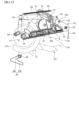
図3〜図5及び図15に示すように、可動通路体400を有する可動通路体装置と、演出可動体500を有する演出可動体装置とは、遊技盤2の背面に固定される四角枠状のベース部材450に設けられている。ベース部材450の背面側には画像表示装置5が設けられ(図1参照)、該ベース部材450の開口を通して前面側から画像表示装置5を視認可能となる。つまり、可動通路体400と演出可動体500とは、遊技盤2と画像表示装置5との間に配設される。
As shown in FIGS. 3 to 5 and 15, the movable passage body device having the
可動通路体400と演出可動体500とは、画像表示装置5の前面周縁部に退避した通路体原点位置及び演出体原点位置(図15(A)参照)と、通路体原点位置及び演出体原点位置から画像表示装置5の前面に出現する通路体進出位置及び演出体進出位置(図15(B)参照)と、の間で移動(動作)可能となっている。尚、可動通路体400が通路体進出位置に配置され、演出可動体500が演出体進出位置に配置されたときでも、可動通路体400の後方に演出可動体500が位置しているので接触することはない。
The
(可動通路体装置)
図15及び図16に示すように、可動通路体400は、左右方向へ直線移動可能に設けられる第1可動部401と、第1可動部401に対して左右方向へ展開及び収束可能に取付けられる第2可動部402と、第1可動部401を左右方向に駆動させる駆動機構403と、から主に構成されている。第1可動部401には、前述した第2誘導経路202Bが形成されている。
(Movable passage body device)
As shown in FIGS. 15 and 16, the
第1可動部401の上端部の前面にはレール部401dが取付けられており、レール部401dは、ベース部材450に固定される上部ガイドレール435に対し左右方向にスライド移動可能に案内されている。また、第1可動部401の背面側下部には、下方に延設される延設部が形成され、該延設部には左右に延びるレール部(図示略)が設けられており、レール部(図示略)は、ベース部材450下部に固定されるガイドレール(図示略)に対し左右方向にスライド移動可能に案内されている。
A
ベース部材450の右側には、通路体原点位置センサ92が設けられており、ベース部材450の左側には、通路体進出位置センサ93が設けられており、可動通路体400が通路体原点位置に位置しているときには、通路体原点位置センサ92により第1可動部401に設けられた検出片が検出され、可動通路体400が通路体進出位置に位置しているときには、通路体進出位置センサ93により検出片が検出されるようになっている。
A passage body
図16に示すように、可動通路体400における第1可動部401は、透過性を有する合成樹脂材により上下に開口する略円筒状に形成されており、背面側に膨出する膨出部413が下部に形成されている。第1可動部401の膨出部413に対応する位置には、上下方向に延びる棒状部材412が配設されており、棒状部材412の外周面には、螺旋状に突出する突条部412aが形成されている。つまり、第2誘導経路202Bは、第1可動部401の内部に形成されており、上部開口である流入口225から第2誘導経路202Bに進入した遊技球は、左右方向に蛇行しながら流下した後、膨出部413の位置において突条部412aに沿って螺旋状に流下し、下部開口である排出口226から排出され、回転体208上に落下する。これにより、第2誘導経路202Bを流下する遊技球に注目させることができ、興趣が向上するとともに、回転体208への落下速度を抑制することで回転体208の破損を防止している。
As shown in FIG. 16, the first
図15に示すように、可動通路体400における第2可動部402は、第1可動部401に対し左右に動作可能に配設される装飾部材404L,404Rを有している。装飾部材404L,404Rは、第1可動部401に対して収束する原点位置である非展開位置(図15(A)参照)と、第1可動部401に対して左右側方に張り出すように展開された展開位置(図15(B)参照)と、に動作可能である。尚、第2可動部402は、可動通路体400が通路体原点位置のときに非展開位置に位置し、可動通路体400が通路体進出位置のときに図示しないリンク機構により展開位置に位置するようになっている。つまり、可動通路体400の移動を利用して非展開位置と展開位置との間で移動可能であることで、可動通路体400を移動させるための通路体用モータ91とは別個の駆動源により動作させる必要がないので、部品点数を削減することができる。
As shown in FIG. 15, the second
尚、装飾部材404L,404Rは、第1可動部401の装飾性を向上させるための飾り部材であり、特に図示しないが、第1可動部401の前面板、背面板及び側面板から平面視略コ字形に形成され、非展開位置にあるときには、左右の装飾部材404L,404Rの間の隙間から第2誘導経路202Bを流下する遊技球を視認可能な第1視認状態とし、展開位置にあるときには、左右の装飾部材404L,404Rが離れて隙間が広がり第2誘導経路202Bを流下する遊技球を第1視認状態よりも視認性が高い第2視認状態とする。
The
(演出可動体装置)
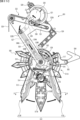
図17〜図19に示すように、演出可動体装置は、四角枠状のベース部材450の左上角部を構成するベース部450Aと、ベース部450Aに対し動作可能に設けられる演出可動体500と、演出可動体500を動作させるための動作機構501と、から主に構成される。演出可動体500は、ベース部450Aの前面に位置する演出体原点位置(図17(A)参照)と、演出体原点位置の右斜め下方の演出体進出位置(図17(B)参照)と、の間で回動可能に設けられている。
(Directive movable body device)
As shown in FIGS. 17 to 19, the effect movable body device includes a
演出可動体500は、第1可動部511と、第1可動部511の背面に突設された前後方向を向く回動軸510を中心として、該第1可動部511の背面側に回動可能に設けられる第2可動部512と、から構成される。
The effect
第1可動部511は、正面視略円形状に形成されるベース部511Aと、ベース部511Aの周縁から回動軸510を中心として放射状に延出される突出片からなる装飾部511Bと、から構成される。装飾部511Bのうち下方に垂下される装飾部511Bの背面側には、前方に向けて光を照射可能な演出体用LED518Aが前面に設けられるとともに、左右側方に向けて光を照射可能な演出体用LED518Bが背面に設けられたLED基板519(図26参照)が設けられている。
The first
また、ベース部511Aの周縁部所定箇所には、連結軸503が前方に向けて突設されており、該連結軸503は、ベース部450Aの左側下部に形成される案内孔504に挿入されている。案内孔504は、第1案内部504Aと第2案内部504Bとにより、正面視略くの字形に形成されており、連結軸503を移動可能に案内する。
Further, a connecting
第2可動部512は、第1可動部511の背面左側及び右側に配置される装飾部512L,512Rからなる。装飾部512L,512Rは、回動軸510を中心として放射状に延出される複数の突出片を有し、第1可動部511の装飾部511Bと略同形状に形成され、第1可動部511の回動軸510を中心として各々回動可能に軸支されるとともに、リンク部材513を介して連結されている。リンク部材513は、第1可動部511の背面における回動軸510の下方に突設された回動軸514を中心として回動可能とされており、一端が装飾部512Lに軸支され、他端が装飾部512Rに軸支されている。また、装飾部512Lにおけるリンク部材513との第1軸支部と装飾部512Rにおけるリンク部材513との第2軸支部とは、回動軸510からの距離が異なっているため、装飾部512L,512Rのうち一方が回動軸510を中心として第1方向に回動することで、リンク部材513が回動軸514を中心に回動するため、他方がリンク部材513を介して第1方向とは逆の第2方向に回動するようになっている。
The second
また、装飾部512Lと装飾部512Rとは、回動軸510と回動軸514との間が引張バネ515により連結されていることで、装飾部512Lと装飾部512Rとが近接する第1装飾状態(図23参照)に維持され、装飾部512Rが第1方向に回動したときには、引張バネ515の付勢力に抗して他方の装飾部512Lが第2方向に回動して、装飾部512Lと装飾部512Rとが離間する第2装飾状態(図25参照)に変化する。また、装飾部512Rは、回動軸510よりも左側に突出する突出片516を有し、該突出片516の背面には連動軸517が突設されている。
Further, the
動作機構501は、ベース部450Aの背面側に固定される演出体用モータ520と、ベース部450Aの前面側に突出した演出体用モータ520の駆動軸(図示略)に固着される回転体521と、ベース部450Aの前面に突設された前後方向を向く回動軸522に回動可能に軸支された第1アーム部材523と、ベース部450Aの前面に突設された回動軸528に回動可能に軸支された第2アーム部材524と、第1アーム部材523に突設された回動軸525に回動可能に軸支された第1リンク部材526と、第1リンク部材526の一端に軸支された第2リンク部材527と、から構成される。尚、回動軸528は、ベース部450Aの前面との間に所定の隙間を隔てて配置されており、該隙間に第1アーム部材523が挿入可能とされている。
The
第1アーム部材523は、第1アーム部523Aと第2アーム部523Bとにより正面視略逆くの字形に形成され、第1アーム部523Aと第2アーム部523Bとの屈曲部が回動軸522により軸支されている。尚、回動軸522にはトーションバネ529が環装されており、第1アーム部材523を上方に向けて付勢している。
The
第1アーム部523Aには、長孔531が形成されており、該長孔531には回転体521の周縁に突設された連結軸530が長手方向に移動可能に挿入されている。第2アーム部523Bは、一端が第1可動部511の回動軸510に回動可能に軸支されている。また、第2アーム部523Bの底壁533の前面には、第2リンク部材527を長手方向に向けて移動案内するための案内軸534A,534Bが突設されているとともに、底壁533の側縁には、第2リンク部材527を長手方向に向けて移動案内するための案内壁535A,535Bが前方に向けて立設されている。このように第2アーム部523Bは、底壁533と案内壁535A,535Bとにより断面視略コ字形に形成されている。
An
第1リンク部材526は、第1アーム部材523の第1アーム部523Aと第2アーム部523Bとの間に突設された回動軸525に回動可能に軸支されている。第1リンク部材526の一端には、第2リンク部材527を軸支する連結軸536が背面側に向けて突設されている。他端には、第1アーム部523Aの長孔531に挿入され前方に突出した連結軸530に接触可能な第1作用部537が形成されている。
The
第2リンク部材527は、第2アーム部523Bの底壁533の前面における案内壁535A,535Bの間に配置されるスライド部538と、スライド部538に対し屈曲して形成され、第2可動部512の連動軸517に接触可能な第2作用部539と、から構成される。スライド部538には、2つの長孔540A,540Bが形成されており、第2アーム部523Bの案内軸534A,534Bがそれぞれ挿入されている。
The
このように構成される第2リンク部材527は、第2アーム部523Bの底壁533の前面における案内壁535A,535Bの間にスライド部538が配置され、該スライド部538は、案内軸534A,534B及び案内壁535A,535Bにより長手方向にスライド移動可能に案内される。つまり、第2リンク部材527は、第2アーム部523Bと同軸方向に移動可能に配置されている。この状態において第2作用部539は、第2アーム部523Bから外方に向けて突出する。また、スライド部538の前面側はカバー部材541により被覆され、第1リンク部材526の前面側はカバー部材542により被覆される。
In the
第2アーム部材524は、正面視略くの字形に形成され、一端がベース部450Aの回動軸528に回動可能に軸支され、他端が第1可動部511の背面における回動軸510の直上に突設された回動軸543に長孔を介して軸支されている。
The
(演出可動体装置の動作例)
次に、演出可動体装置の動作例について、図20〜図26に基づいて説明する。図20は、演出可動体が演出体原点位置に位置している状態を示す概略正面図である。図21は、演出可動体が演出体原点位置と演出体進出位置との間に位置している状態を示す概略正面図である。図22は、演出可動体が演出体進出位置まで移動した状態を示す概略正面図である。図23は、演出可動体が演出体進出位置において第1装飾状態にある状態を示す概略背面図である。図24は、演出可動体が演出体進出位置において第1装飾状態から第2装飾状態に変化した状態を示す概略正面図である。図25は、演出可動体が演出体進出位置において第1装飾状態から第2装飾状態へ変化した状態を示す概略背面図である。図26は、図25のD−D断面図である。尚、図20〜図26において、ベース部など一部の部材の図示は省略している。
(Operation example of production movable body device)
Next, an operation example of the effect movable body device will be described with reference to FIGS. 20 to 26. FIG. 20 is a schematic front view showing a state in which the effect movable body is located at the effect body origin position. FIG. 21 is a schematic front view showing a state in which the effect movable body is located between the effect body origin position and the effect body advance position. FIG. 22 is a schematic front view showing a state in which the effect movable body has moved to the effect body advance position. FIG. 23 is a schematic rear view showing a state in which the effect movable body is in the first decorative state at the effect body advance position. FIG. 24 is a schematic front view showing a state in which the effect movable body changes from the first decorative state to the second decorative state at the effect body advance position. FIG. 25 is a schematic rear view showing a state in which the effect movable body changes from the first decorative state to the second decorative state at the effect body advance position. FIG. 26 is a cross-sectional view taken along the line DD of FIG. In addition, in FIGS. 20 to 26, the illustration of some members such as a base portion is omitted.
図20に示すように、演出可動体500は、演出体原点位置に位置している状態において、装飾部511Bが右側方を向く第1姿勢をなすとともに、該装飾部511Bに装飾部512L,512Rが近接する第1装飾状態とされている。また、回転体521の連結軸530は、回転軸の右側上方において長孔531の回動軸522側の端部に位置していることで、第1アーム部材523の第1アーム部523Aを左斜め上方に持ち上げた状態で保持している。よって、演出可動体500は演出体原点位置に保持される。また、第1アーム部材523はトーションバネ529により上方に付勢されているとともに、第2アーム部材524は、一端がベース部450Aに係止された引張バネ550により上方に付勢されているため、演出可動体500は演出体原点位置に安定して保持される。また、第1可動部511の連結軸503は、第1案内部504Aの右側上端部に位置している。
As shown in FIG. 20, in the effect
第2リンク部材527は、回動軸522側の端部に、一端が第2アーム部523Bにおける回動軸522側に係止された引張バネ551の他端が係止されていることで、回動軸522側の第1スライド位置に保持されている。このとき、第1リンク部材526の第1作用部537は、回転体521の連結軸530から離れている。また、第2リンク部材527の第2作用部539は、装飾部512Rの連動軸517から離れている。
The
図21に示すように、演出体用モータ520により回転体521が反時計回りに回転すると、連結軸530が左側に移動しながら下降していくことで、第1アーム部材523が反時計回りに回動する。演出可動体500は、第1アーム部材523の回動軸522を中心とする回動に応じて下降するとともに、回動軸510よりも左側に連結軸503が位置することで、回動軸510を中心として時計回りに回動する。つまり、演出可動体500は、演出体原点位置から下降しながら回動軸510を中心として時計回りに回動する(第1動作を行う)。尚、連結軸503は、回動軸510が案内孔504に近づくにつれて第1案内部504Aの右端から左端に向けて逃げていく。また、第2リンク部材527は第1スライド位置に保持されたままとなる。
As shown in FIG. 21, when the
次いで、図22及び図23に示すように、回転体521がさらに反時計回りに回転することにより回動軸510が案内孔504から離れていくと、連結軸503は第2案内部504Bを右側下方に向けて移動する。そして、連結軸503が第2案内部504Bの右端部にて移動が規制されることで、第1アーム部材523の回動が規制され、演出可動体500は演出体進出位置にて停止する。
Then, as shown in FIGS. 22 and 23, when the
演出可動体500が演出体進出位置にて移動が規制されて停止した状態では、回転体521の連結軸530は、長孔531の右側において、第1リンク部材526の第1作用部537に近接(または当接)している。また、第2リンク部材527の第2作用部539は、装飾部512Rの連動軸517に近接(または当接)している。そして演出可動体500は、装飾部511Bや装飾部512L,512Rの突出片が下方を向く第2姿勢をなすとともに、該装飾部511Bに装飾部512L,512Rが近接する第1装飾状態とされている。
When the effect
図24及び図25に示すように、回転体521がさらに反時計回りに回転すると、連結軸530が長孔531をさらに右側に移動するが、長孔531の右端部は円弧状に形成されていることから第1アーム部材523は回動しない。そして、連結軸530が第1リンク部材526の第1作用部537に当接して押圧する。これにより、第1リンク部材526が回動軸525を中心として時計回りに回動することで、第2リンク部材527は、引張バネ551の付勢力に抗して、第2アーム部523Bに対し回動軸510側の第2スライド位置に向けて移動する。
As shown in FIGS. 24 and 25, when the
第2リンク部材527が第1スライド位置から第2スライド位置まで移動することで、第2作用部539が装飾部512Rの連動軸517を押圧する。これにより、装飾部512Rが回動軸510を中心として正面視時計回りに回動するとともに、装飾部512Lが回動軸510を中心として正面視反時計回りに回動するため、装飾部512L,512Rの突出片が装飾部511Bから離れる第2装飾状態に変化する。
As the
このように、演出可動体500は、演出体用モータ520により回転体521の連結軸530が回転することで、演出体原点位置から演出体進出位置まで回動しながら下降する第1動作を行った後、さらに回転体521を回転させることで、連結軸530が第1リンク部材526の第1作用部537に作用して第1リンク部材526が回動し、これにより第2リンク部材527が第2アーム部523Bに対しスライド移動し、第2作用部539が装飾部512Rの連動軸517することで、装飾部512L,512Rの突出片が装飾部511Bから離れる方向に回動する第2動作を行うことが可能である。
In this way, the effect
また、演出体用モータ520により回転する回転体521の動力を第2可動部512の装飾部512L,512Rに伝達するための第1リンク部材526や第2リンク部材527は、演出可動体500を回動可能に支持する第1アーム部材523の背面側に遊技者から視認不能に設けられていることで、第1リンク部材526や第2リンク部材527を第1アーム部材523により移動可能に案内することができるため、部品点数を好適に削減することが可能となるとともに、構造を簡素化して見栄えを向上させることができる。
Further, the
また、演出可動体500は、第1アーム部材523により回動軸522を中心として回動可能とされているだけでなく、第1アーム部材523に対し回動軸510を介して回動可能とされ、かつ、回動軸510とは異なる位置に配置された連結軸503が案内孔504に案内されていることで、第1アーム部材523の回動に応じて回動軸510を中心として回動する。よって、一の駆動源により複数個所を動作させることが可能となり、第1動作の動作態様が複雑化するため、興趣が向上する。
Further, the effect
図26に示すように、装飾部511B及び装飾部512L,512Rは、透過性を有する合成樹脂材からなるレンズ部材にて構成されており、装飾部511Bの背面側にはLED基板519が設けられている。LED基板519の前面に設けられた演出体用LED518Aは、前面に対し垂直方向または略垂直方向、つまり、前方に向けて光を照射可能に設けられたトップ型LEDとされている。一方、LED基板519の背面に設けられた演出体用LED518Bは、LED基板519の背面に対し平行方向または略平行方向に光を照射可能なアングル型LEDとされており、外方向に向けて光を照射可能に設けられている。
As shown in FIG. 26, the
演出制御用CPU120は、例えば、後述するように小当り遊技状態においてV入賞が発生したときに、演出可動体500を演出体進出位置まで移動させるとともに、演出体進出位置において第2装飾状態に変化させるタイミングなどにおいて、演出体用LED518A,518Bを発光させることが可能である。演出体用LED518Aからの光は、レンズ部材を通して前方に出射され、演出体用LED518Bからの光は外側方に出射される。よって、演出体用LED518A,518Bを発光させることで、演出体用LED518Aからの光により装飾部511Bの前面が発光するとともに、演出体用LED518Bからの光により、装飾部511Bの外側方に位置する装飾部512L,512Rが照らされて発光する。
For example, when a V prize is generated in the small hit game state, the
このように、第1可動部511に対して動作可能な装飾部512L,512Rに光源を設けることなく、第1可動部511の光源を利用して発光させることができるため、部品点数を削減できるとともに、第1可動部511から第2可動部512への配線等が不要になるので構造を簡素化できる。
As described above, since the light source of the first
また、本実施の形態では、演出制御用CPU120は、小当り遊技状態においてV入賞が発生したときに演出可動体500を演出体原点位置から演出体進出位置まで移動し、第1装飾状態から第2装飾状態に変化するとともに演出体用LED518A,518Bにより発光する形態を例示したが、本発明はこれに限定されるものではなく、演出制御用CPU120は、例えば、小当り遊技状態に制御されたときや可動通路体400が通路体進出位置まで移動したときなどに演出可動体500を演出体進出位置まで移動し、V入賞が発生したときに第1装飾状態から第2装飾状態に変化させたり、演出体用LED518A,518Bを発光させたりしてもよい。また、演出制御用CPU120は、小当り遊技状態以外の所定の演出タイミング(例えば、小当りや大当りの発生を示唆する各種予告演出や、演出大当り中においてラウンド遊技が継続することを報知する大当り中演出や、高ベース状態Aよりも有利な高ベース状態Bに制御されることを示唆する示唆演出等の実行タイミングなど)において演出可動体500を動作させるようにしてもよい。
Further, in the present embodiment, the
また、図15に示すように、可動通路体400は、演出可動体500よりも前方側に配置されている。言い換えれば、可動通路体400と演出可動体500とは、正面視においてそれぞれの動作可能範囲は重複するが、平面視において動作可能範囲が前後にずれて重複しないように配置されているため、演出可動体500が動作可能範囲内の任意の位置にあっても可動通路体400に接触しないようになっている。
Further, as shown in FIG. 15, the
具体的には、演出可動体500が演出体原点位置にあり、可動通路体400が通路体原点位置にある場合には、可動通路体400と演出可動体500とは接触せず(図15(A)参照)、演出可動体500が演出体進出位置にあり、可動通路体400が通路体進出位置にある場合にも可動通路体400と演出可動体500とは接触しない(図15(B)参照)。
Specifically, when the effect
尚、図示しないが、演出可動体500が演出体原点位置と演出体進出位置との間の任意位置に位置しても、可動通路体400と演出可動体500とは接触しない。つまり、可動通路体400と演出可動体500とはいずれのタイミングで動作しても互いに干渉することがないため、可動通路体400と演出可動体500とのうち一方の動作が他方の動作に影響を及ぼすことがない。さらに尚、可動通路体400と演出可動体500とは、動作可能範囲が前後にずれて重複しないように配置されているため、第2可動部402が展開位置または非展開位置に位置しているかに関わらず、演出可動体500が第2可動部402に干渉することがない。
Although not shown, the
また、可動通路体400の第1可動部401は、主基板11に接続される通路体用モータ91により動作する可動部であり、演出可動体500の第1可動部511や第2可動部512は、演出制御基板12に接続される演出体用モータ520により動作する可動部である。
Further, the first
第1可動部401は、小当り遊技状態において最初に第2大入賞口702Bに進入して第1貯留部227に貯留される遊技球P1を、V入賞口283(遊技球が進入することによりCPU103が大当り遊技状態に制御する契機となる入賞口)に進入可能に誘導する第2誘導経路202Aを備えている。つまり、第1可動部401は当否(大当りに制御するか否か)を抽選する当否抽選に関連する遊技用の可動部である一方、第1可動部511や第2可動部512は、第1可動部401のように当否抽選に関わらない演出用の可動部である。
The first
このように、可動通路体400と演出可動体500とが一のベース部材450に設けられている場合、遊技の制御を行うCPU103により可動通路体400と演出可動体500双方の動作を制御することになると、CPU103の制御負荷が大きくなり、遊技に影響を及ぼす可能性があるため、当否抽選といった遊技に関係のない可動部に関しては、他の制御手段である演出制御用CPU120により動作の制御を行うようにすることで、CPU103の処理負荷を好適に軽減することができる。
In this way, when the
しかし、このように当否抽選用の可動通路体400と演出可動体500とを一のベース部材450に搭載する場合、可動通路体400と演出可動体500とのうち一方の動作が他方の動作に干渉する、特に、演出可動体500の動作によって可動通路体400の動作に影響を及ぼすことがあると、当否の抽選、つまり、遊技の結果に影響が及んで遊技の公平性を保つことができなくなる虞がある。よって、可動通路体400と演出可動体500とは、一方の動作が他方の動作に干渉することがないように設けることが好ましい。
However, when the
(遊技の進行の概略)
パチンコ遊技機1が備える打球操作ハンドル30の遊技者による回転操作により、遊技球が遊技領域Yに向けて発射される。遊技球が通過ゲート41を通過すると、普通図柄表示器20による普図ゲームが開始される。
(Outline of the progress of the game)
The game ball is launched toward the game area Y by the rotation operation of the ball striking operation handle 30 included in the
尚、本実施の形態では、前回の普図ゲームの実行期間中や、普図当りに基づき可変入賞球装置6Bが進入可能状態(または後述する開放後時間における進入困難状態)に制御される期間中等に遊技球が通過ゲート41を通過した場合(遊技球が通過ゲート41を通過したが当該通過に基づく普図ゲームを直ちに実行できない場合)には、当該通過に基づく普図ゲームは保留されないが、所定の上限数(例えば4)まで保留されるようにしてもよい。
In the present embodiment, during the execution period of the previous normal map game, or during the period during which the variable winning
この普図の変動表示では、普通図柄の変動を開始させた後、普図変動時間となる所定時間が経過すると、普通図柄の変動表示結果となる確定普通図柄を停止表示(導出表示)する。このとき、確定普通図柄として、例えば「7」を示す数字といった、特定の普通図柄(普図当り図柄)が停止表示されれば、普通図柄の変動表示結果が「普図当り」となる。尚、本実施の形態では、確定普通図柄として、例えば「7」を示す数字以外の数字や記号といった、普図当り図柄以外の普通図柄が停止表示されて、普通図柄の変動表示結果が「普図ハズレ」となることはないが、「普図ハズレ」となることがあるようにしてもよい。普通図柄の変動表示結果が「普図当り」となったことに対応して、可変板が進出位置へ移動して可変入賞球装置6Bが進入可能状態となり、所定時間が経過すると可変板が退避位置へ移動して可変入賞球装置6Bが進入困難状態になる。
In this fluctuation display of the normal symbol, when a predetermined time, which is the fluctuation time of the normal symbol, elapses after the fluctuation of the normal symbol is started, the confirmed normal symbol which is the variation display result of the normal symbol is stopped and displayed (derivated display). At this time, if a specific ordinary symbol (symbol per ordinary symbol) such as a number indicating "7" is stopped and displayed as the confirmed ordinary symbol, the variable display result of the ordinary symbol becomes "per ordinary symbol". In the present embodiment, as the finalized normal symbol, the normal symbol other than the normal symbol, such as a number or symbol other than the number indicating "7", is stopped and displayed, and the variable display result of the normal symbol is "normal". Although it does not result in "figure loss", it may result in "general figure loss". The variable plate moves to the advanced position and the variable winning
入賞球装置6Aに形成された第1始動入賞口に遊技球が進入すると、第1特別図柄表示装置4Aによる第1特図ゲームが開始される。
When the game ball enters the first starting winning opening formed in the winning
可変入賞球装置6Bに形成された第2始動入賞口に遊技球が進入すると、第2特別図柄表示装置4Bによる第2特図ゲームが開始される。
When the game ball enters the second starting winning opening formed in the variable winning
尚、特図ゲームの実行中の期間や、後述する大当り遊技状態や小当り遊技状態に制御されている期間に、遊技球が第1始動入賞口へ進入(入賞)した場合(第1始動入賞が発生したが当該第1始動入賞に基づく第1特図ゲームを直ちに実行できない場合)には、当該進入に基づく第1特図ゲームは所定の上限数(例えば4)までその実行が保留される一方、遊技球が第2始動入賞口へ進入(入賞)した場合(第2始動入賞が発生したが当該第2始動入賞に基づく第2特図ゲームを直ちに実行できない場合)には、当該進入に基づく第2特図ゲームは所定の上限数(例えば3)までその実行が保留される。 In addition, when the game ball enters (wins) the first start winning opening during the period during which the special figure game is being executed or during the period controlled by the big hit game state or the small hit game state described later (first start prize). However, if the first special figure game based on the first start winning cannot be executed immediately), the execution of the first special figure game based on the approach is suspended up to a predetermined upper limit (for example, 4). On the other hand, when the game ball enters (wins) the second start winning opening (when the second start prize occurs but the second special figure game based on the second start prize cannot be executed immediately), the entry is entered. The execution of the second special figure game based on the second special figure game is suspended up to a predetermined upper limit number (for example, 3).
特図ゲームにおいて、所定の特別図柄(小当り図柄、例えば「2」)が停止表示されれば、「小当り」となる。尚、確定特別図柄として特定の特別図柄(大当り図柄、例えば「7」、後述の大当り種別に応じて実際の図柄は異なる。)が停止表示されれば、「大当り」となるようにしてもよい。また、小当り図柄とは異なる特別図柄(ハズレ図柄、例えば「−」)が停止表示されれば「ハズレ」となる。 In the special figure game, if a predetermined special symbol (small hit symbol, for example, "2") is stopped and displayed, it becomes "small hit". If a specific special symbol (big hit symbol, for example, "7", the actual symbol differs depending on the jackpot type described later) is stopped and displayed as the finalized special symbol, it may be set to "big hit". .. Further, if a special symbol (missing symbol, for example, "-") different from the small hit symbol is stopped and displayed, it becomes "missing".
特図ゲームでの表示結果が「小当り」になった後には、小当り遊技状態に制御される。尚、特図ゲームでの表示結果が「大当り」になった後に、遊技者にとって有利な有利状態として大当り遊技状態に制御されるようにしてもよい。 After the display result in the special figure game becomes "small hit", it is controlled to the small hit game state. After the display result in the special figure game becomes "big hit", it may be controlled to the big hit game state as an advantageous state advantageous for the player.
小当り遊技状態では、第2特別可変入賞球装置7Bにより形成される第2大入賞口702Bが所定の開放態様で進入可能状態となる。小当り遊技状態において、第2特別可変入賞球装置7Bの第2大入賞口扉702Aが、所定の上限時間(例えば、1800msなど)が経過するまでの期間あるいは所定個数(例えば8個)の入賞球が発生するまでの期間にて、第2大入賞口702Bを開放状態とする。これにより、第2特別可変入賞球装置7Bは遊技者にとって有利な状態となる。
In the small hit game state, the second large winning
小当り遊技状態において、第2大入賞口702Bに進入した遊技球が第2特別可変入賞球装置7B内に設けられた第3カウントスイッチ24Bを通過すると、該遊技球の第3カウントスイッチ24Bの通過に基づく「大当り(V入賞大当り)」となる。つまり、CPU103は、該遊技球の第3カウントスイッチ24Bの通過を検出したことに基づき、遊技状態を大当り遊技状態に制御する。一方、小当り遊技状態において第2大入賞口702Bに入賞した遊技球が第2特別可変入賞球装置7B内に設けられた第4カウントスイッチ24Cを通過した場合は、「大当り」とはならない。つまり、CPU103は、該遊技球の第4カウントスイッチ24Cの通過を検出したことに基づき、遊技状態を大当り遊技状態には制御しない。
In the small hit game state, when the game ball that has entered the second large winning
そして、遊技球の第3カウントスイッチ24Bの通過に基づいて大当り遊技状態に制御されると、第1特別可変入賞球装置7Aの第1大入賞口扉701Aが、所定の上限時間(例えば29秒間)が経過するまでの期間あるいは所定個数(例えば8個)の入賞が発生するまでの期間にて、第1大入賞口701Bを開放状態とする。これにより、第1特別可変入賞球装置7Aを遊技者にとって有利な開放状態とするラウンド遊技が実行される。尚、本実施の形態では、遊技球の第3カウントスイッチ24Bの通過に基づいて大当り遊技状態に制御されると、第1特別可変入賞球装置7Aが開放状態に制御される形態を例示したが、本発明はこれに限定されるものではなく、第2特別可変入賞球装置7Bが開放状態に制御されるようにしてもよい。
Then, when the big hit game state is controlled based on the passage of the
第1大入賞口の開放サイクルであるラウンドは、その実行回数が所定の上限回数(例えば「5」や「7」や「10」)に達するまで、繰返し実行可能となっている。尚、ラウンドの実行回数が上限回数に達する前であっても、所定条件の成立(例えば第1大入賞口に遊技球が入賞しなかったことなど)により、ラウンドの実行が終了するようにしてもよい。 The round, which is the opening cycle of the first winning opening, can be repeatedly executed until the number of executions reaches a predetermined upper limit (for example, "5", "7", or "10"). Even before the number of times the round is executed reaches the upper limit, the execution of the round is completed when a predetermined condition is satisfied (for example, the game ball did not win the first prize opening). May be good.
本実施の形態における大当り遊技状態の終了後は、時間短縮制御(時短制御)が行われる時短状態に制御される。時短状態では、平均的な特図変動時間(特図を変動させる期間)を通常状態よりも短縮させる制御(時短制御)が実行される。時短状態では、平均的な普図変動時間(普図を変動させる期間)を通常状態よりも短縮させたり、普図ゲームで「普図当り」となる確率を通常状態よりも向上させる等により、第2始動入賞口に遊技球が進入しやすくなる制御(高開放制御、高ベース制御)も実行される。時短状態は、特別図柄(特に第2特別図柄)の変動効率が向上する状態であるので、遊技者にとって有利な状態である。 After the end of the jackpot game state in the present embodiment, the time reduction control (time reduction control) is performed to control the time reduction state. In the time saving state, control (time saving control) is executed in which the average special figure fluctuation time (period in which the special figure is changed) is shortened as compared with the normal state. In the time saving state, the average fluctuation time of the normal map (the period during which the normal map is changed) is shortened from the normal state, and the probability of becoming a "normal map hit" in the normal map game is improved from the normal state. Controls (high opening control, high base control) that make it easier for the game ball to enter the second starting winning opening are also executed. The time saving state is a state in which the fluctuation efficiency of the special symbol (particularly the second special symbol) is improved, which is advantageous for the player.
時短状態は、所定回数(例えば、99回)の特図ゲームが実行されたこと、所定回数(例えば、1回または3回)の小当りが実行されたこと、のうちいずれかの終了条件が先に成立するまで継続する。所定回数の特図ゲームが実行されたことが終了条件となるものを、回数切り(回数切り時短等)ともいう。 The time saving state is determined by the end condition of either that the special figure game has been executed a predetermined number of times (for example, 99 times) or that the small hit has been executed a predetermined number of times (for example, once or three times). Continue until it is established first. A game whose end condition is that the special figure game has been executed a predetermined number of times is also referred to as a number-cutting (time-cutting time reduction, etc.).
通常状態とは、遊技者にとって有利な大当り遊技状態や小当り遊技状態等の有利状態、時短状態等の特別状態以外の遊技状態のことであり、普図ゲームにおける表示結果が「普図当り」となる確率及び特図ゲームにおける表示結果が「小当り」となる確率などが、パチンコ遊技機1の初期設定状態(例えばシステムリセットが行われた場合のように、電源投入後に所定の復帰処理を実行しなかったとき)と同一に制御される状態である。尚、時短制御が実行されている状態を高ベース状態、時短制御が実行されていない状態を低ベース状態ともいう。 The normal state is a gaming state other than a special state such as a big hit game state, a small hit game state, or a short time state, which is advantageous for the player, and the display result in the normal figure game is "normal figure hit". The probability of becoming a "small hit" and the probability that the display result in the special figure game will be a "small hit" are determined by performing a predetermined return process after the power is turned on, such as in the initial setting state of the pachinko gaming machine 1 (for example, when a system reset is performed). It is in the same controlled state as (when not executed). The state in which the time saving control is executed is also referred to as a high base state, and the state in which the time saving control is not executed is also referred to as a low base state.
小当り遊技状態が終了した後、大当り遊技状態にならなかった場合は、遊技状態の変更が行われず、特図ゲームの表示結果が「小当り」となる以前の遊技状態に継続して制御される。尚、遊技状態は、大当り遊技状態中に遊技球が特定領域(例えば、大入賞口内の特定領域)を通過したことに基づいて変化してもよい。例えば、遊技球が特定領域を通過して大当り遊技状態に制御された後は高ベース状態(時短状態)に制御される。 If the big hit game state is not reached after the small hit game state ends, the game state is not changed and the game state before the special figure game display result becomes "small hit" is continuously controlled. NS. The game state may change based on the fact that the game ball has passed through a specific area (for example, a specific area in the big winning opening) during the big hit game state. For example, after the game ball passes through a specific area and is controlled to the big hit game state, it is controlled to the high base state (time saving state).
(演出の進行など)
パチンコ遊技機1では、遊技の進行に応じて種々の演出(遊技の進行状況を報知したり、遊技を盛り上げたりする演出)が実行される。当該演出について以下説明する。尚、当該演出は、画像表示装置5に各種の演出画像を表示することによって行われるが、当該表示に加えて又は代えて、スピーカ8L、8Rからの音声出力、及び/又は、遊技効果ランプ9の点等/消灯、演出可動体500の動作等により行われてもよい。
(Progress of production, etc.)
In the
遊技の進行に応じて実行される演出として、画像表示装置5に設けられた「左」、「中」、「右」の飾り図柄表示エリア5L、5C、5Rでは、第1特図ゲーム又は第2特図ゲームが開始されることに対応して、飾り図柄の可変表示が開始される。第1特図ゲームや第2特図ゲームにおいて表示結果(確定特別図柄ともいう。)が停止表示されるタイミングでは、飾り図柄の可変表示の表示結果となる確定飾り図柄(3つの飾り図柄の組合せ)も停止表示(導出)される。
As an effect executed according to the progress of the game, in the decorative
特図ゲームの表示結果が「小当り」となるときには、画像表示装置5の画面上において、飾り図柄の可変表示の表示結果として、予め定められた小当り組合せとなる確定飾り図柄(例えば、「1 3 5」等)が導出される(飾り図柄の可変表示の表示結果が「小当り」となる)。一例として、「左」、「中」、「右」の飾り図柄表示エリア5L、5C、5Rにおける所定の有効ライン上にチャンス目を構成する飾り図柄が停止表示される。
When the display result of the special figure game is "small hit", a fixed decorative symbol (for example, "for example," 1 3 5 ”etc.) Is derived (the display result of the variable display of the decorative pattern is a“ small hit ”). As an example, the decorative symbols constituting the chance eyes are stopped and displayed on the predetermined effective lines in the decorative
特図ゲームの表示結果が「ハズレ」となる場合には、飾り図柄の可変表示の態様がリーチ態様とならずに、飾り図柄の可変表示の表示結果として、非リーチ組合せの確定飾り図柄(「非リーチハズレ」ともいう。)が停止表示される(飾り図柄の可変表示の表示結果が「非リーチハズレ」となる)ことがある。また、表示結果が「ハズレ」となる場合には、飾り図柄の可変表示の態様がリーチ態様となった後に、飾り図柄の可変表示の表示結果として、小当り組合せでない所定のリーチ組合せ(「リーチハズレ」ともいう)の確定飾り図柄が停止表示される(飾り図柄の可変表示の表示結果が「リーチハズレ」となる)こともある。 When the display result of the special figure game is "missing", the variable display mode of the decorative symbol is not the reach mode, and the variable display result of the decorative symbol is a fixed decorative symbol of a non-reach combination ("" (Also referred to as "non-reach loss") may be stopped and displayed (the display result of the variable display of the decorative pattern may be "non-reach loss"). In addition, when the display result is "missing", after the variable display mode of the decorative symbol becomes the reach mode, the display result of the variable display of the decorative symbol is a predetermined reach combination ("reach loss") that is not a small hit combination. The fixed decorative symbol (also called "") may be stopped and displayed (the display result of the variable display of the decorative symbol may be "reach loss").
パチンコ遊技機1が実行可能な演出には、上記の可変表示対応表示(保留表示やアクティブ表示)を表示することも含まれる。また、他の演出として、例えば、小当り信頼度を予告する予告演出等が飾り図柄の可変表示中に実行される。予告演出には、実行中の可変表示における小当り信頼度を予告する予告演出や、実行前の可変表示(実行が保留されている可変表示)における小当り信頼度を予告する先読み予告演出がある。先読み予告演出として、可変表示対応表示(保留表示やアクティブ表示)の表示態様を通常とは異なる態様に変化させる演出が実行されるようにしてもよい。
The effect that the
また、画像表示装置5において、飾り図柄の可変表示中に飾り図柄を一旦仮停止させた後に可変表示を再開させることで、1回の可変表示を擬似的に複数回の可変表示のように見せる擬似連演出を実行するようにしてもよい。
Further, in the
大当り遊技状態中にも、大当り遊技状態を報知する大当り中演出が実行される。大当り中演出としては、ラウンド数を報知する演出や、大当り遊技状態の価値が向上することを示す昇格演出が実行されてもよい。また、小当り遊技状態中にも、小当り遊技状態を報知する小当り中演出が実行される。 Even during the big hit game state, the big hit middle effect that notifies the big hit game state is executed. As the big hit middle effect, an effect of notifying the number of rounds and a promotion effect indicating that the value of the big hit gaming state is improved may be executed. Further, even during the small hit game state, the small hit medium effect for notifying the small hit game state is executed.
また、例えば特図ゲーム等が実行されていないときには、画像表示装置5にデモ(デモンストレーション)画像が表示される(客待ちデモ演出が実行される)。 Further, for example, when a special figure game or the like is not executed, a demo (demonstration) image is displayed on the image display device 5 (a customer waiting demo effect is executed).
(基板構成)
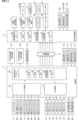
パチンコ遊技機1には、例えば図2に示すような主基板11、演出制御基板12、音声制御基板13、ランプ制御基板14、中継基板15などが搭載されている。その他にも、パチンコ遊技機1の背面には、例えば払出制御基板、情報端子基板、発射制御基板、電源基板などといった、各種の基板が配置されている。
(Board configuration)
For example, the
主基板11は、メイン側の制御基板であり、パチンコ遊技機1における上記遊技の進行(特図ゲームの実行(保留の管理を含む)、普図ゲームの実行(保留の管理を含む)、大当り遊技状態、小当り遊技状態、遊技状態など)を制御する機能を有する。主基板11は、遊技制御用マイクロコンピュータ100、スイッチ回路110、ソレノイド回路111などを有する。
The main board 11 is a control board on the main side, and the progress of the above-mentioned game in the pachinko game machine 1 (execution of a special figure game (including management of hold), execution of a normal figure game (including management of hold), and a big hit. It has a function to control a gaming state, a small hit gaming state, a gaming state, etc.). The main board 11 includes a
主基板11に搭載された遊技制御用マイクロコンピュータ100は、例えば1チップのマイクロコンピュータであり、ROM(Read Only Memory)101と、RAM(Random Access Memory)102と、CPU(Central Processing Unit)103と、乱数回路104と、I/O(Input/Output port)105とを備える。
The
CPU103は、ROM101に記憶されたプログラムを実行することにより、遊技の進行を制御する処理(主基板11の機能を実現する処理)を行う。このとき、ROM101が記憶する各種データ(後述の変動パターン、後述の演出制御コマンド、後述の各種決定を行う際に参照される各種テーブルなどのデータ)が用いられ、RAM102がメインメモリとして使用される。RAM102は、その一部または全部がパチンコ遊技機1に対する電力供給が停止しても、所定期間記憶内容が保存されるバックアップRAMとなっている。尚、ROM101に記憶されたプログラムの全部又は一部をRAM102に展開して、RAM102上で実行するようにしてもよい。
The
乱数回路104は、遊技の進行を制御するときに使用される各種の乱数値(遊技用乱数)を示す数値データを更新可能にカウントする。遊技用乱数は、CPU103が所定のコンピュータプログラムを実行することで更新されるもの(ソフトウェアで更新されるもの)であってもよい。
The
I/O105は、例えば各種信号(後述の検出信号)が入力される入力ポートと、各種信号(第1特別図柄表示装置4A、第2特別図柄表示装置4B、普通図柄表示器20、第1保留表示器25A、第2保留表示器25Bなどを制御(駆動)する信号、ソレノイド駆動信号)を伝送するための出力ポートとを含んで構成される。
The I /
スイッチ回路110は、遊技球検出用の各種スイッチ(ゲートスイッチ21、始動口スイッチ(第1始動口スイッチ22Aおよび第2始動口スイッチ22B)、カウントスイッチ23)からの検出信号(遊技球が通過又は進入してスイッチがオンになったことを示す検出信号など)を取り込んで遊技制御用マイクロコンピュータ100に伝送する。検出信号の伝送により、遊技球の通過又は進入が検出されたことになる。
The
ソレノイド回路111は、遊技制御用マイクロコンピュータ100からのソレノイド駆動信号(例えば、ソレノイド81やソレノイド82をオンする信号など)を、普通電動役物用のソレノイド81や大入賞口扉用のソレノイド82に伝送する。
The solenoid circuit 111 transmits a solenoid drive signal (for example, a signal for turning on the
主基板11(遊技制御用マイクロコンピュータ100)は、遊技の進行の制御の一部として、遊技の進行に応じて演出制御コマンド(遊技の進行状況等を指定(通知)するコマンド)を演出制御基板12に供給する。主基板11から出力された演出制御コマンドは、中継基板15により中継され、演出制御基板12に供給される。当該演出制御コマンドには、例えば主基板11における各種の決定結果(例えば、特図ゲームの表示結果(大当り種別を含む。)、特図ゲームを実行する際に使用される変動パターン(詳しくは後述))、遊技の状況(例えば、可変表示の開始や終了、大入賞口の開放状況、入賞の発生、保留記憶数、遊技状態)、エラーの発生等を指定するコマンド等が含まれる。
The main board 11 (
演出制御基板12は、主基板11とは独立したサブ側の制御基板であり、演出制御コマンドを受信し、受信した演出制御コマンドに基づいて演出(遊技の進行に応じた種々の演出であり、演出可動体500の駆動、エラー報知、電断復旧の報知等の各種報知を含む)を実行する機能を有する。
The effect control board 12 is a control board on the sub side independent of the main board 11, receives an effect control command, and produces an effect (various effects according to the progress of the game) based on the received effect control command. It has a function of executing various notifications (including various notifications such as driving of the
演出制御基板12には、演出制御用CPU120と、ROM121と、RAM122と、表示制御部123と、乱数回路124と、I/O125とが搭載されている。
The effect control board 12 is equipped with an
演出制御用CPU120は、ROM121に記憶されたプログラムを実行することにより、表示制御部123とともに演出を実行するための処理(演出制御基板12の上記機能を実現するための処理であり、実行する演出の決定等を含む)を行う。このとき、ROM121が記憶する各種データ(各種テーブルなどのデータ)が用いられ、RAM122がメインメモリとして使用される。
The
演出制御用CPU120は、コントローラセンサユニット35Aやプッシュセンサ35Bからの検出信号(遊技者による操作を検出したときに出力される信号であり、操作内容を適宜示す信号)に基づいて演出の実行を表示制御部123に指示することもある。
The
表示制御部123は、VDP(Video Display Processor)、CGROM(Character Generator ROM)、VRAM(Video RAM)などを備え、演出制御用CPU120からの演出の実行指示に基づき、演出を実行する。
The
表示制御部123は、演出制御用CPU120からの演出の実行指示に基づき、実行する演出に応じた映像信号を画像表示装置5に供給することで、演出画像を画像表示装置5に表示させる。表示制御部123は、さらに、演出画像の表示に同期した音声出力や、遊技効果ランプ9の点灯/消灯を行うため、音指定信号(出力する音声を指定する信号)を音声制御基板13に供給したり、ランプ信号(ランプの点灯/消灯態様を指定する信号)をランプ制御基板14に供給したりする。また、表示制御部123は、演出可動体500を動作させる信号を当該演出可動体500又は当該演出可動体500を駆動する駆動回路に供給する。
The
音声制御基板13は、スピーカ8L、8Rを駆動する各種回路を搭載しており、当該音指定信号に基づきスピーカ8L、8Rを駆動し、当該音指定信号が指定する音声をスピーカ8L、8Rから出力させる。
The
ランプ制御基板14は、遊技効果ランプ9を駆動する各種回路を搭載しており、当該ランプ信号に基づき遊技効果ランプ9を駆動し、当該ランプ信号が指定する態様で遊技効果ランプ9を点灯/消灯する。このようにして、表示制御部123は、音声出力、ランプの点灯/消灯を制御する。
The
尚、音声出力、ランプの点灯/消灯の制御(音指定信号やランプ信号の供給等)、演出可動体500の制御(演出可動体500を動作させる信号の供給等)は、演出制御用CPU120が実行するようにしてもよい。
It should be noted that the
乱数回路124は、各種演出を実行するために使用される各種の乱数値(演出用乱数)を示す数値データを更新可能にカウントする。演出用乱数は、演出制御用CPU120が所定のコンピュータプログラムを実行することで更新されるもの(ソフトウェアで更新されるもの)であってもよい。
The
演出制御基板12に搭載されたI/O125は、例えば主基板11などから伝送された演出制御コマンドを取り込むための入力ポートと、各種信号(映像信号、音指定信号、ランプ信号)を伝送するための出力ポートとを含んで構成される。
The I /
演出制御基板12、音声制御基板13、ランプ制御基板14といった、主基板11以外の基板をサブ基板ともいう。パチンコ遊技機1のようにサブ基板が機能別に複数設けられていてもよいし、1のサブ基板が複数の機能を有するように構成してもよい。
Boards other than the main board 11, such as the effect control board 12, the
図27(A)は、本実施の形態で用いられる演出制御コマンドの内容の一例を示す説明図である。演出制御コマンドは、例えば2バイト構成であり、1バイト目はMODE(コマンドの分類)を示し、2バイト目はEXT(コマンドの種類)を表す。MODEデータの先頭ビット(ビット7)は必ず「1」とされ、EXTデータの先頭ビットは「0」とされる。尚、図27(A)に示されたコマンド形態は一例であって、他のコマンド形態を用いてもよい。また、この例では、制御コマンドが2つの制御信号で構成されることになるが、制御コマンドを構成する制御信号数は、1であってもよいし、3以上の複数であってもよい。 FIG. 27A is an explanatory diagram showing an example of the contents of the effect control command used in the present embodiment. The effect control command has, for example, a 2-byte structure, the first byte represents MODE (command classification), and the second byte represents EXT (command type). The first bit (bit 7) of the MODE data is always set to "1", and the first bit of the EXT data is set to "0". The command form shown in FIG. 27A is an example, and other command forms may be used. Further, in this example, the control command is composed of two control signals, but the number of control signals constituting the control command may be one or a plurality of three or more.
図27(A)に示す例において、コマンド8001Hは、第1特別図柄表示装置4Aにおける第1特図を用いた特図ゲームにおける可変表示の開始を指定する第1可変表示開始コマンドである。コマンド8002Hは、第2特別図柄表示装置4Bにおける第2特図を用いた特図ゲームにおける可変表示の開始を指定する第2可変表示開始コマンドである。コマンド81XXHは、特図ゲームにおける特別図柄の可変表示に対応して画像表示装置5における「左」、「中」、「右」の各飾り図柄表示エリア5L,5C,5Rで可変表示される飾り図柄(演出図柄ともいう)などの変動パターン(変動時間(可変表示時間))を指定する変動パターン指定コマンドである。ここで、XXHは不特定の16進数であることを示し、演出制御コマンドによる指示内容に応じて任意に設定される値であればよい。尚、変動パターン指定コマンドでは、指定する変動パターンなどに応じて、異なるEXTデータが設定される。
In the example shown in FIG. 27 (A), the command 8001H is the first variable display start command for designating the start of the variable display in the special figure game using the first special figure in the first special
コマンド8CXXHは、可変表示結果指定コマンドであり、特別図柄や飾り図柄などの可変表示結果を指定する演出制御コマンドである。可変表示結果指定コマンドでは、例えば図27(B)に示すように、可変表示結果(変動表示結果ともいう)が「ハズレ」であるか「小当り」であるかの決定結果(事前決定結果)や、可変表示結果が「小当り」となる場合の小当り種別を複数種類のいずれとするかの決定結果(小当り種別決定結果)に応じて、異なるEXTデータが設定される。 The command 8CXXXH is a variable display result designation command, and is an effect control command for designating a variable display result such as a special symbol or a decorative symbol. In the variable display result specification command, for example, as shown in FIG. 27 (B), the determination result (predetermined result) of whether the variable display result (also referred to as the variable display result) is “miss” or “small hit”. Alternatively, different EXT data are set according to the determination result (small hit type determination result) of which of the plurality of small hit types is used when the variable display result is "small hit".
可変表示結果指定コマンドでは、例えば、図27(B)に示すように、コマンド8C00Hは、可変表示結果が「ハズレ」となる旨の事前決定結果を示す第1可変表示結果指定コマンドである。コマンド8C01Hは、可変表示結果が「小当り」で小当り種別が「小当り1」となる旨の事前決定結果及び小当り種別決定結果を通知する第2可変表示結果指定コマンドである。コマンド8C02Hは、可変表示結果が「小当り」で小当り種別が「小当り2」となる旨の事前決定結果及び小当り種別決定結果を通知する第3可変表示結果指定コマンドである。コマンド8C03Hは、可変表示結果が「小当り」で小当り種別が「小当り3」となる旨の事前決定結果及び小当り種別決定結果を通知する第4可変表示結果指定コマンドである。コマンド8C04Hは、可変表示結果が「小当り」で小当り種別が「小当り4」となる旨の事前決定結果及び小当り種別決定結果を通知する第5可変表示結果指定コマンドである。コマンド8C05Hは、可変表示結果が「小当り」で小当り種別が「小当り5」となる旨の事前決定結果及び小当り種別決定結果を通知する第6可変表示結果指定コマンドである。コマンド8C06Hは、可変表示結果が「小当り」で小当り種別が「小当り6」となる旨の事前決定結果及び小当り種別決定結果を通知する第7可変表示結果指定コマンドである。コマンド8C07Hは、可変表示結果が「小当り」で小当り種別が「小当り7」となる旨の事前決定結果及び小当り種別決定結果を通知する第8可変表示結果指定コマンドである。コマンド8C08Hは、可変表示結果が「小当り」で小当り種別が「小当り8」となる旨の事前決定結果及び小当り種別決定結果を通知する第9可変表示結果指定コマンドである。コマンド8C09Hは、可変表示結果が「小当り」で小当り種別が「小当り9」となる旨の事前決定結果及び小当り種別決定結果を通知する第10可変表示結果指定コマンドである。コマンド8C0AHは、可変表示結果が「小当り」で小当り種別が「小当り10」となる旨の事前決定結果及び小当り種別決定結果を通知する第11可変表示結果指定コマンドである。コマンド8C0BHは、可変表示結果が「小当り」で小当り種別が「小当り11」となる旨の事前決定結果及び小当り種別決定結果を通知する第12可変表示結果指定コマンドである。コマンド8C0CHは、可変表示結果が「小当り」で小当り種別が「小当り12」となる旨の事前決定結果及び小当り種別決定結果を通知する第13可変表示結果指定コマンドである。
In the variable display result designation command, for example, as shown in FIG. 27 (B), the command 8C00H is the first variable display result designation command indicating a predetermined result indicating that the variable display result is “missing”. The command 8C01H is a second variable display result designation command for notifying the pre-determined result that the variable display result is "small hit" and the small hit type is "
コマンド8F00Hは、画像表示装置5における「左」、「中」、「右」の各飾り図柄表示エリア5L,5C,5Rで飾り図柄の変動停止(確定)を指定する図柄確定コマンドである。コマンド95XXHは、パチンコ遊技機1における現在の遊技状態を指定する遊技状態指定コマンドである。遊技状態指定コマンドでは、例えばパチンコ遊技機1における現在の遊技状態に応じて、異なるEXTデータが設定される。具体的な一例として、コマンド9500Hを時短制御が行われない遊技状態(低ベース状態、通常状態)に対応した第1遊技状態指定コマンドとし、コマンド9501Hを時短制御が1回行われる遊技状態(高ベース状態A、時短状態A)に対応した第2遊技状態指定コマンドとし、コマンド9502Hを時短制御が3回行われる遊技状態(高ベース状態B、時短状態B)に対応した第3遊技状態指定コマンドとする。
The command 8F00H is a symbol confirmation command for designating the change stop (confirmation) of the decorative symbol in each of the “left”, “middle”, and “right” decorative
コマンド96XXHは、パチンコ遊技機1においてエラー(異常)の発生および発生したエラー(異常)の種別を指定するエラー(異常)指定コマンドである。エラー(異常)指定コマンドでは、例えば、各エラー(異常)に対応するEXTデータが設定されることにより、演出制御基板12側において、いずれのエラー(異常)の発生が判定されたのかを特定することができ、特定したエラー(異常)の発生がエラー報知処理によって報知される。
The command 96XXH is an error (abnormal) designation command that specifies the occurrence of an error (abnormality) and the type of the error (abnormality) that has occurred in the
コマンドA0XXHは、大当り遊技や小当り遊技の開始を示す演出画像の表示を指定する当り開始指定コマンド(「ファンファーレコマンド」ともいう)である。コマンドA1XXHは、大当り遊技状態において、大入賞口が開放状態となっている期間であることを通知する大入賞口開放中通知コマンドである。コマンドA2XXHは、大当り遊技状態において、大入賞口が開放状態から閉鎖状態に変化した期間であることを通知する大入賞口開放後通知コマンドである。コマンドA3XXHは、大当り遊技や小当りの終了時における演出画像の表示を指定する当り終了指定コマンドである。コマンドA4XXHは、後述する促進演出の開始を指定する促進演出開始指定コマンドである。 The command A0XXH is a hit start designation command (also referred to as a "fanfare command") for designating the display of an effect image indicating the start of a big hit game or a small hit game. The command A1XXH is a notification command during the opening of the big winning opening that notifies that the big winning opening is in the open state in the big hit game state. The command A2XXH is a notification command after opening the big winning opening that notifies that it is a period during which the big winning opening has changed from the open state to the closed state in the big hit game state. The command A3XXH is a hit end designation command for designating the display of the effect image at the end of the big hit game or the small hit. The command A4XXH is a promotion effect start designation command that specifies the start of the promotion effect described later.
当り開始指定コマンドや当り終了指定コマンドでは、例えば可変表示結果指定コマンドと同様のEXTデータが設定されることなどにより、事前決定結果や大当り種別決定結果に応じて異なるEXTデータが設定されてもよい。あるいは、当り開始指定コマンドや当り終了指定コマンドでは、事前決定結果及び大当り種別決定結果と設定されるEXTデータとの対応関係を、可変表示結果指定コマンドにおける対応関係とは異ならせるようにしてもよい。大入賞口開放中通知コマンドや大入賞口開放後通知コマンドでは、例えば、後述する通常開放大当り状態や高速開放大当り状態におけるラウンドの実行回数(例えば「1」〜「16」)に対応して、異なるEXTデータが設定される。 In the hit start designation command and the hit end designation command, different EXT data may be set according to the pre-determination result and the jackpot type determination result, for example, by setting the same EXT data as the variable display result specification command. .. Alternatively, in the hit start designation command or the hit end designation command, the correspondence between the pre-determined result and the jackpot type determination result and the set EXT data may be different from the correspondence in the variable display result specification command. .. In the notification command during the opening of the large winning opening and the notification command after opening the large winning opening, for example, the number of round executions (for example, "1" to "16") in the normal open big hit state and the high-speed open big hit state, which will be described later, is supported. Different EXT data are set.
コマンドB100Hは、入賞球装置6Aが形成する第1始動入賞口を通過(進入)した遊技球が第1始動口スイッチ22Aにより検出されて始動入賞(第1始動入賞)が発生したことに基づき、第1特別図柄表示装置4Aにおける第1特図を用いた特図ゲームを実行するための第1始動条件が成立したことを通知する第1始動口入賞指定コマンドである。コマンドB200Hは、可変入賞球装置6Bが形成する第2始動入賞口を通過(進入)した遊技球が第2始動口スイッチ22Bにより検出されて始動入賞(第2始動入賞)が発生したことに基づき、第2特別図柄表示装置4Bにおける第2特図を用いた特図ゲームを実行するための第2始動条件が成立したことを通知する第2始動口入賞指定コマンドである。
The command B100H is based on the fact that the game ball that has passed (entered) the first starting winning opening formed by the winning
コマンドC1XXHは、特図保留記憶数を特定可能とするために、第1特図保留記憶数を通知する第1保留記憶数通知コマンドである。コマンドC2XXHは、特図保留記憶数を特定可能とするために、第2特図保留記憶数を通知する第2保留記憶数通知コマンドである。第1保留記憶数通知コマンドは、例えば第1始動入賞口を遊技球が通過(進入)して第1始動条件が成立したことに基づいて、第1始動口入賞指定コマンドが送信されるときに、主基板11から演出制御基板12に対して送信される。第2保留記憶数通知コマンドは、例えば第2始動入賞口を遊技球が通過(進入)して第2始動条件が成立したことに基づいて、第2始動口入賞指定コマンドが送信されるときに、主基板11から演出制御基板12に対して送信される。また、第1保留記憶数通知コマンドや第2保留記憶数通知コマンドは、第1開始条件と第2開始条件のいずれかが成立したとき(保留記憶数が減少したとき)に、特図ゲームの実行が開始されることなどに対応して送信されるようにしてもよい。 The command C1XXH is a first hold storage number notification command for notifying the first special figure hold storage number in order to make it possible to specify the special figure hold storage number. The command C2XXH is a second hold storage number notification command for notifying the second special figure hold storage number in order to make it possible to specify the special figure hold storage number. The first hold memory number notification command is, for example, when the first start opening prize designation command is transmitted based on the fact that the game ball passes (enters) the first start winning opening and the first starting condition is satisfied. , Is transmitted from the main board 11 to the effect control board 12. The second hold memory number notification command is, for example, when the second start opening prize designation command is transmitted based on the fact that the game ball passes (enters) the second start winning opening and the second starting condition is satisfied. , Is transmitted from the main board 11 to the effect control board 12. Further, the first hold storage number notification command and the second hold storage number notification command are used in the special figure game when either the first start condition or the second start condition is satisfied (when the hold storage number decreases). It may be transmitted in response to the start of execution.
第1保留記憶数通知コマンドや第2保留記憶数通知コマンドに代えて、合計保留記憶数を通知する合計保留記憶数通知コマンドを送信するようにしてもよい。即ち、合計保留記憶数の増加(または減少)を通知するための合計保留記憶数通知コマンドが用いられてもよい。 Instead of the first hold storage number notification command and the second hold storage number notification command, the total hold storage number notification command for notifying the total hold storage number may be transmitted. That is, a total hold storage number notification command may be used to notify an increase (or decrease) of the total hold storage number.
コマンドD100は、V入賞が発生したこと、つまり、遊技球が第3カウントスイッチ24Bを通過したことで第3カウントスイッチ24Bがオンとなったことを通知するV入賞通知指定コマンドである。
The command D100 is a V winning notification designation command for notifying that a V winning has occurred, that is, that the
尚、図27(A)に示すコマンドは一例であり、これらのコマンドの一部を有しないものであってもよいし、これらのコマンドに代えて異なるコマンドを用いてもよいし、これらのコマンドと異なるコマンドを追加してもよい。例えば、各入賞口に遊技球が入賞したことに基づいて払い出される賞球数を特定可能とするための賞球数通知コマンドや、遊技球が通過ゲート41を通過したことを通知するためのゲート通過通知コマンドや、確変制御や時短制御が実行される残りの回数を通知する通知コマンド等を設けるようにしてもよい。
The command shown in FIG. 27 (A) is an example, and may not have a part of these commands, or a different command may be used instead of these commands, or these commands may be used. You may add a command different from. For example, a prize ball number notification command for making it possible to specify the number of prize balls to be paid out based on the winning of a game ball at each winning opening, or a gate for notifying that the game ball has passed through the passing
図28は、主基板11の側においてカウントされる乱数値を例示する説明図である。図28に示すように、この実施の形態では、主基板11の側において、特図表示結果判定用の乱数値MR1、大当り種別判定用の乱数値MR2、変動パターン判定用の乱数値MR3、普図表示結果判定用の乱数値MR4のそれぞれを示す数値データが、カウント可能に制御される。尚、遊技効果を高めるために、これら以外の乱数値が用いられてもよい。こうした遊技の進行を制御するために用いられる乱数は、遊技用乱数ともいう。 FIG. 28 is an explanatory diagram illustrating a random number value counted on the side of the main board 11. As shown in FIG. 28, in this embodiment, on the side of the main board 11, the random number value MR1 for determining the special figure display result, the random number value MR2 for determining the jackpot type, the random number value MR3 for determining the fluctuation pattern, and the usual Numerical data indicating each of the random number values MR4 for determining the figure display result is controlled so as to be countable. In addition, a random number value other than these may be used in order to enhance the game effect. Random numbers used to control the progress of such games are also called game random numbers.
乱数回路104は、これらの乱数値MR1〜MR4の一部または全部を示す数値データをカウントするものであればよい。CPU103は、例えば図28に示す遊技制御カウンタ設定部(図示略)に設けられたランダムカウンタといった、乱数回路104とは異なるランダムカウンタを用いて、ソフトウェアによって各種の数値データを更新することで、乱数値MR1〜MR4の一部を示す数値データをカウントするようにしてもよい。
The
特図表示結果判定用の乱数値MR1は、特図ゲームにおける特別図柄などの可変表示結果を「小当り」として大当り遊技状態に制御するか否かを決定するために用いられる乱数値であり、例えば「1」〜「65536」の範囲の値をとる。大当り種別判定用の乱数値MR2は、可変表示結果を「小当り」とする場合における大当り種別を「小当り1〜10」のいずれかに決定するために用いられる乱数値であり、例えば「0」〜「299」の範囲の値をとる。
The random number value MR1 for determining the special figure display result is a random number value used to determine whether or not to control the variable display result such as a special symbol in the special figure game as a "small hit" to the big hit game state. For example, it takes a value in the range of "1" to "65536". The random value MR2 for determining the jackpot type is a random number value used to determine the jackpot type to be one of "
変動パターン判定用の乱数値MR3は、特別図柄や飾り図柄の可変表示における変動パターンを、予め用意された複数種類のいずれかに決定するために用いられる乱数値であり、例えば「1」〜「997」の範囲の値をとる。 The random value MR3 for determining the fluctuation pattern is a random value used to determine the fluctuation pattern in the variable display of the special symbol or the decorative symbol to any of a plurality of types prepared in advance, and is, for example, "1" to "1" to "". It takes a value in the range of 997.
普図表示結果判定用の乱数値MR4は、普通図柄表示器20による普図ゲームにおける可変表示結果を「普図当り」とするか「普図ハズレ」とするかなどの決定を行うために用いられる乱数値であり、例えば「3」〜「23」の範囲の値をとる。
The random number value MR4 for determining the normal figure display result is used to determine whether the variable display result in the normal figure game by the
図29は、特別図柄の変動パターンの一例を示す説明図である。本実施の形態では、可変表示結果が「ハズレ」となる場合に対応する変動パターン(PA1−1)と、可変表示結果が「小当り」となる場合に対応する複数の変動パターン(PB2−1,PB2−2,PB2−3,PB2−4)が予め用意されている。 FIG. 29 is an explanatory diagram showing an example of a variation pattern of a special symbol. In the present embodiment, a fluctuation pattern (PA1-1) corresponding to the case where the variable display result is "missing" and a plurality of fluctuation patterns (PB2-1) corresponding to the case where the variable display result is "small hit". , PB2-2, PB2-3, PB2-4) are prepared in advance.
複数の変動パターン(PB2−1,PB2−2,PB2−3,PB2−4)の特図可変表示時間については、「ハズレ」となる場合に対応する変動パターン(PA1−1)よりも長く設定されている。また、大当り終了後に時短制御が3回実行されるまで継続する高ベース状態Bにおいては、大当り終了後に時短制御が1回実行されるまで継続する高ベース状態Aである場合よりも変動時間が長い変動パターンPB2−4が実行されるように設定されている。 The special figure variable display time of a plurality of fluctuation patterns (PB2-1, PB2-2, PB2-3, PB2-4) is set longer than the fluctuation pattern (PA1-1) corresponding to the case of "loss". Has been done. Further, in the high base state B that continues until the time reduction control is executed three times after the end of the big hit, the fluctuation time is longer than in the case of the high base state A that continues until the time reduction control is executed once after the end of the big hit. The variation pattern PB2-4 is set to be executed.
具体的には、図29(A)に示すように、低ベース状態または高ベース状態A,Bにおける第1特別図柄の変動パターンとしては、表示結果がハズレの場合にはハズレ変動パターンPB1−1を決定し、表示結果が小当りの場合は小当り変動パターンPB2−1を決定する。図29(B)に示すように、低ベース状態における第2特別図柄の変動パターンとしては、表示結果が小当りの場合は小当り変動パターンPB2−2を決定する。図29(C)に示すように、高ベース状態Aにおける第2特別図柄の変動パターンとしては、表示結果が小当りで、特図の保留記憶数が2〜4個の場合は小当り変動パターンPB2−1を決定し、表示結果が小当りで、特図の保留記憶数が0〜1個の場合は小当り変動パターンPB2−3を決定する。図29(D)に示すように、高ベース状態Bにおける第2特別図柄の変動パターンとしては、小当り変動パターンPB2−4を決定する。 Specifically, as shown in FIG. 29 (A), as the fluctuation pattern of the first special symbol in the low base state or the high base states A and B, when the display result is lost, the loss fluctuation pattern PB1-1 If the display result is a small hit, the small hit fluctuation pattern PB2-1 is determined. As shown in FIG. 29 (B), as the fluctuation pattern of the second special symbol in the low base state, the small hit fluctuation pattern PB2-2 is determined when the display result is a small hit. As shown in FIG. 29 (C), as the fluctuation pattern of the second special symbol in the high base state A, when the display result is a small hit and the number of reserved storages of the special symbol is 2 to 4, the small hit fluctuation pattern PB2-1 is determined, and when the display result is a small hit and the number of reserved storages in the special figure is 0 to 1, the small hit fluctuation pattern PB2-3 is determined. As shown in FIG. 29 (D), the small hit variation pattern PB2-4 is determined as the variation pattern of the second special symbol in the high base state B.
尚、本実施の形態では、上記変動パターンPB1−1、PB2−1〜4については、図柄確定時間(特別図柄の最小停止表示時間)は、低ベース状態及び高ベース状態A,Bで共通の500msとされている。また、上記変動パターン以外の変動パターンを設定してもよいし、各変動パターンの変動時間も任意に変更可能である。 In the present embodiment, for the fluctuation patterns PB1-1 and PB2-1 to 4, the symbol determination time (minimum stop display time of the special symbol) is common to the low base state and the high base states A and B. It is said to be 500 ms. Further, a fluctuation pattern other than the above fluctuation pattern may be set, and the fluctuation time of each fluctuation pattern can be arbitrarily changed.
図30(A)は、ROM101に記憶される特図表示結果判定テーブルの構成例を示している。特図表示結果判定テーブルは、第1特別図柄表示装置4Aによる第1特図を用いた特図ゲームや第2特別図柄表示装置4Bによる第2特図を用いた特図ゲームにおいて可変表示結果となる確定特別図柄が導出表示される以前に、その可変表示結果を「小当り」として小当り遊技状態に制御するか否かを、特図表示結果判定用の乱数値MR1に基づいて決定するために参照されるテーブルである。
FIG. 30A shows a configuration example of a special figure display result determination table stored in the
本実施の形態における特図表示結果判定テーブルでは、第1特別図柄表示装置4Aによる第1特図を用いた特図ゲームであるか、第2特別図柄表示装置4Bによる第2特図を用いた特図ゲームであるかに応じて、特図表示結果判定用の乱数値MR1と比較される数値(判定値)が、「小当り」や「ハズレ」の特図表示結果に割り当てられている。
In the special figure display result determination table in the present embodiment, either the special figure game using the first special figure by the first special
特図表示結果判定テーブルでは、第2特別図柄表示装置4Bによる第2特図を用いた特図ゲームであるときに、第1特別図柄表示装置4Aによる第1特図を用いた特図ゲームであるときよりも多くの判定値が、「小当り」の特図表示結果に割り当てられている。これにより、第2特別図柄表示装置4Bによる第2特図を用いた特図ゲームでは、第1特別図柄表示装置4Aによる第1特図を用いた特図ゲームであるときに特図表示結果を「小当り」として小当り遊技状態に制御すると決定される確率(本実施の形態では1/70)に比べて、特図表示結果を「小当り」として小当り遊技状態に制御すると決定される確率が高くなる(本実施の形態では1/1)。つまり、第2特図ゲームの方が第1特図ゲームよりも遊技者にとって有利度合いが高いゲームとなる。
In the special figure display result determination table, when the special figure game using the second special figure by the second special
尚、第2特図ゲームの方が第1特図ゲームよりも遊技者にとって有利度合いが高いゲームとなれば、第2特図ゲームの小当り確率は1/2〜1/5など、種々に変更可能であり、第2特図ゲームにおいて特図表示結果が所定の確率で「ハズレ」となるようにしてもよい。また、このように第2特図ゲームの特図表示結果として「ハズレ」を含むようにした場合でも、第2特図ゲームの方が第1特図ゲームよりも特図表示結果を「小当り」として小当り遊技状態に制御すると決定される確率が高くなるようにすることが好ましい。 If the second special figure game has a higher degree of advantage for the player than the first special figure game, the small hit probability of the second special figure game varies from 1/2 to 1/5. It can be changed, and the special figure display result may be "lost" with a predetermined probability in the second special figure game. Further, even when the special figure display result of the second special figure game includes "miss" in this way, the second special figure game has a "small hit" of the special figure display result than the first special figure game. It is preferable that the probability of being determined to control the small hit game state is high.
また、図30(B)に示すように、本実施の形態では、前回の特図ゲームの実行中の期間等に遊技球が第1始動入賞口を通過した場合(遊技球が第1始動入賞口を通過したが当該通過に基づく特図ゲームを直ちに実行できない場合)には、当該通過に基づく特図ゲームを所定の第1上限数(例えば4)まで保留され、前回の特図ゲームの実行中の期間等に遊技球が第2始動入賞口を通過した場合(遊技球が第2始動入賞口を通過したが当該通過に基づく特図ゲームを直ちに実行できない場合)には、当該通過に基づく特図ゲームを所定の第2上限数(例えば3)まで保留されるようになっている。 Further, as shown in FIG. 30B, in the present embodiment, when the game ball passes through the first start winning opening during the period during the execution of the previous special figure game or the like (the game ball passes the first start winning prize). If the special figure game based on the passage cannot be executed immediately after passing through the mouth), the special figure game based on the passage is suspended up to the predetermined first upper limit number (for example, 4), and the previous special figure game is executed. If the game ball passes through the second start winning opening during the middle period (when the game ball passes through the second starting winning opening but the special figure game based on the passage cannot be executed immediately), it is based on the passage. The special figure game is held up to a predetermined second upper limit number (for example, 3).
また、本実施の形態では、CPU103は、第1保留記憶と第2保留記憶とがある場合、第2保留記憶に基づく第2特図の可変表示を、第1保留記憶に基づく第1特図の可変表示よりも優先して実行するようになっている。
Further, in the present embodiment, when the
また、図30(C)に示すように、本実施の形態では、大当りの終了後に実行される高ベース状態Aの終了条件は、大当り終了後における第1特図を用いた特図ゲームと第2特図を用いた特図ゲームとの合算可変表示回数が99回に達したこと、または、大当り終了後において小当り遊技状態が実行された回数(高ベース状態Aにおける第2特図ゲームの実行回数)が第1回数(例えば1回)に達したこと、のうちいずれかにより成立する。一方、大当りの終了後に実行される高ベース状態Bの終了条件は、大当り終了後における第1特図を用いた特図ゲームと第2特図を用いた特図ゲームとの合算可変表示回数が99回に達したこと、または、大当り終了後において小当り遊技状態が実行された回数(高ベース状態Bにおける第2特図ゲームの実行回数)が第2回数(例えば3回)に達したこと、のうちいずれかにより成立する。尚、高ベース状態A,Bは、大当り遊技状態に制御されたときにも終了する。 Further, as shown in FIG. 30C, in the present embodiment, the end conditions of the high base state A executed after the end of the big hit are the special figure game using the first special figure after the end of the big hit and the first special figure game. 2 The total variable display number with the special figure game using the special figure has reached 99 times, or the number of times the small hit game state has been executed after the end of the big hit (of the second special figure game in the high base state A). It is established by either of the fact that the number of executions (the number of executions) reaches the first number (for example, once). On the other hand, the end condition of the high base state B executed after the end of the big hit is the total variable display number of the special figure game using the first special figure and the special figure game using the second special figure after the end of the big hit. It has reached 99 times, or the number of times the small hit game state has been executed after the end of the big hit (the number of times the second special figure game has been executed in the high base state B) has reached the second number (for example, 3 times). , Whichever is true. The high base states A and B also end when the jackpot game state is controlled.
また、高ベース状態A,Bの終了条件である特図ゲームの実行回数は、上記99回に限らず、任意に変更可能である。また、高ベース状態Aと高ベース状態Bとで回数を異ならせてもよい。また、高ベース状態A,Bの終了条件である小当り遊技状態の実行回数は、上記1回や3回に限らず、任意に変更可能である。 Further, the number of times the special figure game, which is the end condition of the high base states A and B, is executed is not limited to the above 99 times, and can be arbitrarily changed. Further, the number of times may be different between the high base state A and the high base state B. Further, the number of executions of the small hit game state, which is the end condition of the high base states A and B, is not limited to the above one or three times, and can be arbitrarily changed.
図31(A)は、ROM101に記憶されている小当り種別判定テーブルAを示す説明図である。小当り種別判定テーブルAは、低ベース状態において第1特図を用いた特図ゲームが実行されて表示結果を小当りにする旨の判定がなされたときに、当り種別判定用の乱数(MR4)に基づいて、小当りの種別を小当り1〜小当り4のいずれかに決定するために参照されるテーブルである。尚、本実施の形態における小当り種別判定テーブルAにおいては、当り種別判定用の乱数(MR4)の取り得る範囲0〜299のうち、0〜134までが小当り1、135〜269までが小当り2、270〜289までが小当り3、290〜299までが小当り4に割り当てられている。
FIG. 31 (A) is an explanatory diagram showing a small hit type determination table A stored in the
図31(B)は、ROM101に記憶されている小当り種別判定テーブルBを示す説明図である。小当り種別判定テーブルBは、高ベース状態A,Bにおいて第1特図を用いた特図ゲームが実行されて表示結果を小当りにする旨の判定がなされたときに、当り種別判定用の乱数(MR4)に基づいて、小当りの種別を小当り1〜小当り4のいずれかに決定するために参照されるテーブルである。尚、本実施の形態における小当り種別判定テーブルBにおいては、当り種別判定用の乱数(MR4)の取り得る範囲0〜299のうち、0〜134までが小当り1、135〜269までが小当り2、270〜289までが小当り3、290〜299までが小当り4に割り当てられている。
FIG. 31B is an explanatory diagram showing a small hit type determination table B stored in the
図31(C)は、ROM101に記憶されている小当り種別判定テーブルCを示す説明図である。小当り種別判定テーブルCは、低ベース状態または高ベース状態A,Bにおいて第2特図を用いた特図ゲームが実行されて表示結果を小当りにする旨の判定がなされたときに、当り種別判定用の乱数(MR4)に基づいて、小当りの種別を小当り5〜小当り10のいずれかに決定するために参照されるテーブルである。尚、本実施の形態における小当り種別判定テーブルCにおいては、当り種別判定用の乱数(MR4)の取り得る範囲0〜299のうち、0〜39までが小当り5、40〜89までが小当り6、90〜99までが小当り7、110〜129までが小当り8、130〜179までが小当り9、180〜239までが小当り10、240〜259までが小当り11、260〜299までが小当り12に割り当てられている。
FIG. 31 (C) is an explanatory diagram showing a small hit type determination table C stored in the
本実施の形態において、小当り1、3、5、9は、小当り遊技状態において第2大入賞口702Bが開放パターンAに基づいて1回開放されることにより回転体208にサポート球を最多で1個供給可能となる。また、小当り2、4、6、10は、小当り遊技状態において第2大入賞口702Bが開放パターンBに基づいて2回開放されることにより回転体208にサポート球を最多で3個供給可能となる。また、小当り7、11は、小当り遊技状態において第2大入賞口702Bが開放パターンCに基づいて3回開放されることにより回転体208にサポート球を最多で5個供給可能となる。また、小当り8、12は、小当り遊技状態において第2大入賞口702Bが開放パターンDに基づいて1回開放されることにより回転体208にサポート球を最多で1個供給可能となった後、該サポート球の排出を実行した後、さらにもう1回開放されることにより回転体208にサポート球を最多で1個供給可能となる。
In the present embodiment, the
本実施の形態では、1回の開放において148msの短時間開放を600ms間隔で2回または3回繰り返す制御が行われる。つまり、開放パターンAでは、148msの短時間開放を3回繰り返す開放制御が1回実行され(図50参照)、開放パターンBでは、148msの短時間開放を3回繰り返す開放制御が2回実行され(図51参照)、開放パターンCでは、148msの短時間開放を2回繰り返す開放制御が3回実行される(図52参照)。開放パターンDでは、148msの短時間開放を3回繰り返す開放制御が1回実行され(図50参照)、サポート球の排出を実行した後、さらにもう1回、148msの短時間開放を3回繰り返す開放制御が1回実行される(図55、図56参照)。 In the present embodiment, control is performed in which a short-time opening of 148 ms is repeated two or three times at 600 ms intervals in one opening. That is, in the opening pattern A, the opening control that repeats the short-time opening of 148 ms three times is executed once (see FIG. 50), and in the opening pattern B, the opening control that repeats the short-time opening of 148 ms three times is executed twice. (See FIG. 51), in the opening pattern C, the opening control in which the short-time opening of 148 ms is repeated twice is executed three times (see FIG. 52). In the opening pattern D, the opening control of repeating the short-time opening of 148 ms three times is executed once (see FIG. 50), the support ball is discharged, and then the short-time opening of 148 ms is repeated three times. The release control is executed once (see FIGS. 55 and 56).
尚、1回の開放において短時間開放を2回または4回以上繰り返してもよいし、複数回の短時間開放の合算時間に相当する時間の開放を1回実行してもよい。また、148msの短時間開放では、開放時に第2大入賞口扉702Aの上面にある遊技球Pが1個進入可能であるが、開放時に複数の遊技球Pが第2大入賞口扉702Aの上面を流下している場合、開放時に複数個の遊技球Pが入賞することもある。
It should be noted that the short-time opening may be repeated two or four times or more in one opening, or the opening for a time corresponding to the total time of the plurality of short-time opening may be executed once. Further, when the door is opened for a short time of 148 ms, one game ball P on the upper surface of the second big winning
また、小当り1〜4は、小当り遊技中に遊技球が第3カウントスイッチ24Bを通過した場合、すなわち、V入賞大当りが発生した場合は、ラウンド遊技が7回実行される大当りAが実行される。また、小当り1、2については、低ベース状態で小当りとなった場合には、大当り遊技状態の終了後は高ベース状態Aに制御され、高ベース状態A,Bで小当りとなった場合には、大当り遊技状態の終了後は高ベース状態Bに制御される。小当り3、4については、低ベース状態または高ベース状態A,Bで小当りとなった場合でも、大当り遊技状態の終了後は高ベース状態Bに制御される。
Further, in the
また、小当り5〜8は、小当り遊技中に遊技球が第3カウントスイッチ24Bを通過した場合、すなわち、V入賞大当りが発生した場合は、ラウンド遊技が5回実行される大当りCが実行される。また、小当り9〜12は、小当り遊技中に遊技球が第3カウントスイッチ24Bを通過した場合、すなわち、V入賞大当りが発生した場合は、ラウンド遊技が10回実行される大当りDが実行される。尚、各大当りA〜Dのラウンド回数は、V入賞時が1ラウンドであるため、実質ラウンド数は規定ラウンド数からV入賞ラウンドを減算した値となる。
Further, in the
また、小当り5〜12については、低ベース状態または高ベース状態A,Bで小当りとなった場合でも、大当り遊技状態の終了後は高ベース状態Bに制御される。
Further, regarding the
このように、本実施の形態では、低ベース状態における第1特図ゲームで小当りを契機として大当りとなった場合、大当りの終了後は高ベース状態Bよりも高い割合で高ベース状態Aに制御される一方で、高ベース状態A,Bにおける第1特図ゲームまたは第2特図ゲームで小当りを契機として大当りとなった場合、大当りの終了後は高ベース状態Aよりも高い割合で高ベース状態Bに制御される。 As described above, in the present embodiment, when a big hit is triggered by a small hit in the first special figure game in the low base state, after the big hit ends, the high base state A is set at a higher rate than the high base state B. While being controlled, if a big hit is triggered by a small hit in the first special figure game or the second special figure game in the high base states A and B, the rate is higher than that in the high base state A after the big hit ends. It is controlled to the high base state B.
つまり、低ベース状態である場合、大当りとなる確率及び大当りの終了後に高ベース状態Bに制御される確率は低いが、高ベース状態Aにおける第2特図ゲームで小当りを契機として大当りになると、大当り終了後は全て高ベース状態Aよりも時短回数が多い高ベース状態Bに制御されることで、第2特図ゲームで小当りを契機として大当りになる確率が高まるため、大当りの連荘を期待できるようになっている。 That is, in the case of the low base state, the probability of becoming a big hit and the probability of being controlled to the high base state B after the end of the big hit are low, but when the small hit becomes a big hit in the second special figure game in the high base state A, it becomes a big hit. After the big hit, all are controlled to the high base state B, which has more time reductions than the high base state A, so the probability of becoming a big hit in the second special figure game is increased, so the big hit consecutive villa Can be expected.
尚、本実施の形態では、低ベース状態における第1特図ゲームで小当りを契機として大当りとなった場合、小当り種別により高ベース状態Aまたは高ベース状態Bのいずれかに制御される形態を例示したが、本発明はこれに限定されるものではなく、低ベース状態における第1特図ゲームで小当りを契機として大当りとなった場合は小当り種別に関係なく高ベース状態Aに制御されるようにしてもよい。また、高ベース状態A,Bにおける第2特図ゲームで小当りを契機として大当りとなった場合、小当り種別に関係なく高ベース状態Bに制御される形態を例示したが、高ベース状態Aや低ベース状態に制御されるようにしてもよい。 In the present embodiment, when a big hit is triggered by a small hit in the first special figure game in the low base state, it is controlled to either the high base state A or the high base state B depending on the small hit type. However, the present invention is not limited to this, and when a big hit is triggered by a small hit in the first special figure game in the low base state, it is controlled to the high base state A regardless of the small hit type. It may be done. Further, in the second special figure game in the high base states A and B, when a big hit is triggered by a small hit, a mode in which the high base state B is controlled regardless of the small hit type is illustrated. Or may be controlled to a low base state.
また、本実施の形態では、大当りの終了後は全て高ベース状態A,Bのいずれか制御される形態を例示したが、本発明はこれに限定されるものではなく、大当りの終了後に低ベース状態に制御される小当り種別を有していてもよい。 Further, in the present embodiment, all of the high base states A and B are controlled after the end of the big hit, but the present invention is not limited to this, and the low base is used after the end of the big hit. It may have a small hit type controlled by the state.
また、本実施の形態では、大当り終了後に時短制御が1回実行されるまで継続する高ベース状態Aと、時短制御が3回実行されるまで継続する高ベース状態Bのいずれかに制御される小当り種別1〜12を有する形態を例示したが、本発明はこれに限定されるものではなく、時短制御が2回または4回以上実行されるまで継続する高ベース状態のいずれかに制御される小当り種別を有していてもよい。
Further, in the present embodiment, it is controlled to either a high base state A that continues until the time saving control is executed once after the end of the big hit, or a high base state B that continues until the time saving control is executed three times. Although the embodiment having the
図32(A)は、低ベース状態において決定される普通図柄の変動パターンを示している。本実施の形態では、可変表示結果が「普図当り」となる場合に対応する変動パターンPC1−1が予め用意され、「普図ハズレ」となる場合に対応する変動パターンは用意されていない。変動パターンPC1−1は、普図の変動表示時間は3000msであり、図柄確定時間(普通図柄の最小停止表示時間)は4msとされている。 FIG. 32 (A) shows a variation pattern of a normal symbol determined in a low base state. In the present embodiment, the variation pattern PC1-1 corresponding to the case where the variable display result is "per ordinary figure" is prepared in advance, and the variation pattern corresponding to the case where the variable display result is "missing ordinary figure" is not prepared. In the fluctuation pattern PC1-1, the fluctuation display time of the normal symbol is 3000 ms, and the symbol confirmation time (minimum stop display time of the normal symbol) is 4 ms.
図32(B)は、高ベース状態A,Bにおいて決定される普通図柄の変動パターンを示している。本実施の形態では、可変表示結果が「普図当り」となる場合に対応する変動パターンPC1−2が予め用意され、「普図ハズレ」となる場合に対応する変動パターンは用意されていない。変動パターンPC1−2は、普図の変動表示時間は48msであり、図柄確定時間(普通図柄の最小停止表示時間)は4msとされている。つまり、普図の変動表示時間は、高ベース状態A,Bにおいて低ベース状態であるときよりも短くなるが、図柄確定時間は低ベース状態と高ベース状態A,Bとで共通である。 FIG. 32 (B) shows the variation pattern of the normal symbol determined in the high base states A and B. In the present embodiment, the variation pattern PC1-2 corresponding to the case where the variable display result is "per ordinary figure" is prepared in advance, and the variation pattern corresponding to the case where the variable display result is "missing ordinary figure" is not prepared. In the fluctuation pattern PC1-2, the fluctuation display time of the normal symbol is 48 ms, and the symbol confirmation time (minimum stop display time of the normal symbol) is 4 ms. That is, the fluctuation display time of the normal figure is shorter in the high base states A and B than in the low base state, but the symbol determination time is common to the low base states and the high base states A and B.
図32(C)は、普図当りに基づく第2始動入賞口の開放内容を示している。普図当りに基づき第2始動入賞口を開放する開放タイミング(普図が停止表示されたタイミング)において、遊技状態が低ベース状態である場合は、第2始動入賞口の開放時間は16ms、開放後時間(可変入賞球装置6Bを進入困難状態に維持する期間)は4048msとなる。一方、普図当りに基づき第2始動入賞口を開放する開放タイミング(普図が停止表示されたタイミング)において、遊技状態が高ベース状態A,Bである場合は、第2始動入賞口の開放時間は5500ms、開放後時間(可変入賞球装置6Bを進入困難状態に維持する期間)は4048msとなる。
FIG. 32 (C) shows the opening contents of the second start winning opening based on the normal drawing. If the game state is in a low base state at the opening timing (timing when the normal drawing is stopped and displayed) to open the second starting winning opening based on the normal drawing, the opening time of the second starting winning opening is 16 ms and is open. The post-time (the period during which the variable winning
図32(D)は、ROM101に記憶される普図表示結果判定テーブルの構成例を示している。本実施の形態では、普図表示結果判定テーブルとして、普図ゲームにおいて可変表示結果となる確定普通図柄が導出表示される以前に、その可変表示結果を「普図当り」として可変入賞球装置6Bを進入可能状態に制御するか否かを、普図表示結果判定用の乱数値MR4に基づいて決定するために参照されるテーブルである。
FIG. 32 (D) shows a configuration example of a normal map display result determination table stored in the
本実施の形態における普図表示結果判定テーブルでは、遊技状態が低ベース状態であるか高ベース状態A,Bのいずれであるかに応じて、普図表示結果判定用の乱数値MR4と比較される数値(判定値)が、全て「普図当り」の表示結果に割り当てられている。つまり、本実施の形態では、遊技状態が低ベース状態または高ベース状態A,Bであっても、普図ゲームであるときに普図表示結果を所定の確率(本実施の形態では1/1)で「普図当り」として可変入賞球装置6Bを進入可能状態に制御すると決定する。
In the normal map display result determination table in the present embodiment, it is compared with the random number value MR4 for determining the normal map display result according to whether the game state is the low base state or the high base state A or B. All numerical values (judgment values) are assigned to the display result of "per ordinary figure". That is, in the present embodiment, even if the gaming state is the low base state or the high base states A and B, the normal map display result is set to a predetermined probability (1/1 in the present embodiment) in the normal map game. ) To control the variable winning
尚、本実施の形態では、普図ゲームであるときに普図表示結果を1/1の確率で普図当りとする形態を例示したが、本発明はこれに限定されるものではなく、上記確率よりも低い確率で普図当りを決定する、つまり、「普図ハズレ」を決定可能としてもよい。 In addition, in the present embodiment, an embodiment in which the normal figure display result is hit by the normal figure with a probability of 1/1 in the normal figure game is illustrated, but the present invention is not limited to this, and the above is not limited to this. It may be possible to determine the hit of the normal figure with a probability lower than the probability, that is, to determine the "loss of the normal figure".
図32(E)は、普図ゲームにおける各種決定内容が示されている。本実施の形態では、遊技球がゲートスイッチ21を通過したことに基づいて普図の可変表示開始条件が成立した場合、遊技状態が低ベース状態であるか高ベース状態A,Bであるかに応じて、普図当りにするか否か(実際には普図当りにすること)及び普図変動パターンを決定する。
FIG. 32 (E) shows various determination contents in the normal drawing game. In the present embodiment, when the variable display start condition of the normal figure is satisfied based on the fact that the game ball has passed through the
一方、第2始動入賞口の開放パターン(開放時間)については、普図ゲームの可変表示の表示結果が導出表示されたタイミングで、遊技状態が低ベース状態である場合はショート開放パターン(16ms)を決定し、遊技状態が高ベース状態A,Bである場合はロング開放パターン(5500ms)を決定する。 On the other hand, regarding the opening pattern (opening time) of the second start winning opening, the short opening pattern (16 ms) is obtained when the game state is the low base state at the timing when the display result of the variable display of the normal figure game is derived and displayed. Is determined, and when the gaming states are the high base states A and B, the long open pattern (5500 ms) is determined.
このように、CPU103は、普図ゲームの普図表示結果を普図当りとするか否か及び普図変動パターンについては、普図の可変表示開始条件が成立したタイミングで決定する一方で、第2始動入賞口の開放パターン(開放時間)については、普図ゲームの可変表示の表示結果が導出表示(普図当り図柄が停止表示)されたタイミングにおいて、遊技状態が低ベース状態と高ベース状態A,Bのいずれであるかによって決定する。
In this way, the
また、第2始動入賞口の閉鎖条件は、第2始動入賞口をショート開放パターンまたはロング開放パターンのいずれの態様で開放した場合でも、第2始動入賞口を開放してから開放時間が経過したこと、または、開放時間が経過する前であっても2個の遊技球が入賞(第2始動口スイッチ22Bによって検出された)したことのいずれかに基づいて成立し、可変入賞球装置6Bが進入困難状態に制御されるようになっている。尚、本実施の形態では、2個の遊技球が入賞したことで可変入賞球装置6Bが進入困難状態に制御されるようになっているが、1個または3個以上の遊技球が入賞したことで可変入賞球装置6Bが進入困難状態に制御されるようにしてもよい。
Further, as for the closing condition of the second starting winning opening, regardless of whether the second starting winning opening is opened in the short opening pattern or the long opening pattern, the opening time has elapsed since the second starting winning opening was opened. It is established based on either that, or two game balls have won a prize (detected by the second
また、普図確定時間(4ms)、第2始動入賞口開放時間(16msや5500ms)、開放後時間(4048ms)等については、上記時間に限らす、種々に変更可能である。 Further, the normal drawing confirmation time (4 ms), the second start winning opening opening time (16 ms or 5500 ms), the opening time (4048 ms), and the like can be variously changed, limited to the above time.
(動作)
次に、パチンコ遊技機1の動作(作用)を説明する。
(motion)
Next, the operation (action) of the
(主基板11の主要な動作)
まず、主基板11における主要な動作を説明する。パチンコ遊技機1に対して電力供給が開始されると、遊技制御用マイクロコンピュータ100が起動し、CPU103によって遊技制御メイン処理が実行される。図33は、主基板11におけるCPU103が実行する遊技制御メイン処理を示すフローチャートである。
(Main operation of main board 11)
First, the main operations on the main board 11 will be described. When the power supply to the
図33に示す遊技制御メイン処理では、CPU103は、まず、割込禁止に設定する(ステップS1)。続いて、必要な初期設定を行う(ステップS2)。初期設定には、スタックポインタの設定、内蔵デバイス(CTC(カウンタ/タイマ回路)、パラレル入出力ポート等)のレジスタ設定、RAM102をアクセス可能状態にする設定等が含まれる。
In the game control main process shown in FIG. 33, the
次いで、クリアスイッチからの出力信号がオンであるか否かを判定する(ステップS3)。クリアスイッチは、例えば電源基板に搭載されている。クリアスイッチがオンの状態で電源が投入されると、出力信号(クリア信号)が入力ポートを介して遊技制御用マイクロコンピュータ100に入力される。クリアスイッチからの出力信号がオンである場合(ステップS3;Yes)、初期化処理(ステップS8)を実行する。初期化処理では、CPU103は、RAM102に記憶されるフラグ、カウンタ、バッファをクリアするRAMクリア処理を行い、作業領域に初期値を設定する。
Next, it is determined whether or not the output signal from the clear switch is ON (step S3). The clear switch is mounted on the power supply board, for example. When the power is turned on with the clear switch turned on, an output signal (clear signal) is input to the
また、CPU103は、初期化を指示する演出制御コマンドを演出制御基板12に送信する(ステップS9)。演出制御用CPU120は、当該演出制御コマンドを受信すると、例えば画像表示装置5において、遊技機の制御の初期化がなされたことを報知するための画面表示を行う。
Further, the
クリアスイッチからの出力信号がオンでない場合には(ステップS3;No)、RAM102(バックアップRAM)にバックアップデータが保存されているか否かを判定する(ステップS4)。不測の停電等(電断)によりパチンコ遊技機1への電力供給が停止したときには、CPU103は、当該電力供給の停止によって動作できなくなる直前に、電源供給停止時処理を実行する。この電源供給停止時処理では、RAM102にデータをバックアップすることを示すバックアップフラグをオンする処理、RAM102のデータ保護処理等が実行される。データ保護処理には、誤り検出符号(チェックサム、パリティビット等)の付加、各種データをバックアップする処理が含まれる。バックアップされるデータには、遊技を進行するための各種データ(各種フラグ、各種タイマの状態等を含む)の他、前記バックアップフラグの状態や誤り検出符号も含まれる。ステップS4では、バックアップフラグがオンであるか否かを判定する。バックアップフラグがオフでRAM102にバックアップデータが記憶されていない場合(ステップS4;No)、初期化処理(ステップS8)を実行する。
If the output signal from the clear switch is not on (step S3; No), it is determined whether or not the backup data is stored in the RAM 102 (backup RAM) (step S4). When the power supply to the
RAM102にバックアップデータが記憶されている場合(ステップS4;Yes)、CPU103は、バックアップしたデータのデータチェックを行い(誤り検出符号を用いて行われる)、データが正常か否かを判定する(ステップS5)。ステップS5では、例えば、パリティビットやチェックサムにより、RAM102のデータが、電力供給停止時のデータと一致するか否かを判定する。これらが一致すると判定された場合、RAM102のデータが正常であると判定する。
When the backup data is stored in the RAM 102 (step S4; Yes), the
RAM102のデータが正常でないと判定された場合(ステップS5;No)、内部状態を電力供給停止時の状態に戻すことができないので、初期化処理(ステップS8)を実行する。
If it is determined that the data in the
RAM102のデータが正常であると判定された場合(ステップS5;Yes)、CPU103は、主基板11の内部状態を電力供給停止時の状態に戻すための復旧処理(ステップS6)を行う。復旧処理では、CPU103は、RAM102の記憶内容(バックアップしたデータの内容)に基づいて作業領域の設定を行う。これにより、電力供給停止時の遊技状態に復旧し、特別図柄の変動中であった場合には、後述の遊技制御用タイマ割込み処理の実行によって、復旧前の状態から特別図柄の変動が再開されることになる。
When it is determined that the data in the
そして、CPU103は、電断からの復旧を指示する演出制御コマンドを演出制御基板12に送信する(ステップS7)。これに合わせて、バックアップされている電断前の遊技状態を指定する演出制御コマンドや、特図ゲームの実行中であった場合には当該実行中の特図ゲームの表示結果を指定する演出制御コマンドを送信するようにしてもよい。これらコマンドは、後述の特別図柄プロセス処理で送信設定されるコマンドと同じコマンドを使用できる。演出制御用CPU120は、電断からの復旧時を特定する演出制御コマンドを受信すると、例えば画像表示装置5において、電断からの復旧がなされたこと又は電断からの復旧中であることを報知するための画面表示を行う。演出制御用CPU120は、前記演出制御コマンドに基づいて、適宜の画面表示を行うようにしてもよい。
Then, the
復旧処理または初期化処理を終了して演出制御基板12に演出制御コマンドを送信した後には、CPU103は、乱数回路104を初期設定する乱数回路設定処理を実行する(ステップS10)。そして、所定時間(例えば2ms)毎に定期的にタイマ割込がかかるように遊技制御用マイクロコンピュータ100に内蔵されているCTCのレジスタの設定を行い(ステップS11)、割込みを許可する(ステップS12)。その後、ループ処理に入る。以後、所定時間(例えば2ms)ごとにCTCから割込み要求信号がCPU103へ送出され、CPU103は定期的にタイマ割込み処理を実行することができる。
After the restoration process or the initialization process is completed and the effect control command is transmitted to the effect control board 12, the
こうした遊技制御メイン処理を実行したCPU103は、CTCからの割込み要求信号を受信して割込み要求を受け付けると、図34のフローチャートに示す遊技制御用タイマ割込み処理を実行する。図34に示す遊技制御用タイマ割込み処理を開始すると、CPU103は、まず、所定のスイッチ処理を実行することにより、スイッチ回路110を介してゲートスイッチ21、第1始動口スイッチ22A、第2始動口スイッチ22B、カウントスイッチ23といった各種スイッチからの検出信号の受信の有無を判定する(ステップS21)。続いて、所定のメイン側エラー処理を実行することにより、パチンコ遊技機1の異常診断を行い、その診断結果に応じて必要ならば警告を発生可能とする(ステップS22)。この後、所定の情報出力処理を実行することにより、例えばパチンコ遊技機1の外部に設置されたホール管理用コンピュータに供給される大当り情報(大当りの発生回数等を示す情報)、始動情報(始動入賞の回数等を示す情報)、確率変動情報(確変状態となった回数等を示す情報)などのデータを出力する(ステップS23)。
When the
情報出力処理に続いて、主基板11の側で用いられる遊技用乱数の少なくとも一部をソフトウェアにより更新するための遊技用乱数更新処理を実行する(ステップS24)。この後、CPU103は、特別図柄プロセス処理を実行する(ステップS25)。CPU103がタイマ割込み毎に特別図柄プロセス処理を実行することにより、特図ゲームの実行及び保留の管理や、大当り遊技状態や小当り遊技状態の制御、遊技状態の制御などが実現される(詳しくは後述)。
Following the information output process, a game random number update process for updating at least a part of the game random numbers used on the main board 11 side by software is executed (step S24). After that, the
特別図柄プロセス処理に続いて、普通図柄プロセス処理が実行される(ステップS26)。CPU103がタイマ割込み毎に普通図柄プロセス処理を実行することにより、ゲートスイッチ21からの検出信号に基づく(通過ゲート41に遊技球が通過したことに基づく)普図ゲームの実行及び保留の管理や、「普図当り」に基づく可変入賞球装置6Bの開放制御などを可能にする。普図ゲームの実行は、普通図柄表示器20を駆動することにより行われる。
Following the special symbol process processing, the normal symbol process processing is executed (step S26). By executing the normal symbol process processing for each timer interrupt, the
普通図柄プロセス処理を実行した後、遊技制御用タイマ割込み処理の一部として、電断が発生したときの処理、賞球を払い出すための処理等などが行われてもよい。その後、CPU103は、コマンド制御処理を実行する(ステップS27)。CPU103は、上記各処理にて演出制御コマンドを送信設定することがある。ステップS27のコマンド制御処理では、送信設定された演出制御コマンドを演出制御基板12などのサブ側の制御基板に対して伝送させる処理が行われる。コマンド制御処理を実行した後には、割込みを許可してから、遊技制御用タイマ割込み処理を終了する。
After executing the normal symbol process process, as a part of the game control timer interrupt process, a process when a power failure occurs, a process for paying out a prize ball, and the like may be performed. After that, the
図35は、特別図柄プロセス処理として、図34に示すステップS25にて実行される処理の一例を示すフローチャートである。この特別図柄プロセス処理において、CPU103は、まず、始動入賞判定処理を実行する(ステップS101)。
FIG. 35 is a flowchart showing an example of the process executed in step S25 shown in FIG. 34 as the special symbol process process. In this special symbol process process, the
始動入賞判定処理では、始動入賞の発生を検出し、RAM102の所定領域に保留情報を格納し保留記憶数を更新する処理が実行される。始動入賞が発生すると、表示結果(大当り種別を含む)や変動パターンを決定するための乱数値が抽出され、保留情報として記憶される。また、抽出した乱数値に基づいて、表示結果や変動パターンを先読み判定する処理が実行されてもよい。保留情報や保留記憶数を記憶した後には、演出制御基板12に始動入賞の発生、保留記憶数、先読み判定等の判定結果を指定するための演出制御コマンドを送信するための送信設定が行われる。こうして送信設定された始動入賞時の演出制御コマンドは、例えば特別図柄プロセス処理が終了した後、図34に示すステップS27のコマンド制御処理が実行されることなどにより、主基板11から演出制御基板12に対して伝送される。
In the start winning determination process, a process of detecting the occurrence of a start winning, storing the hold information in a predetermined area of the
S101にて始動入賞判定処理を実行した後、CPU103は、RAM102に設けられた特図プロセスフラグの値に応じて、ステップS110〜S120の処理のいずれかを選択して実行する。尚、特別図柄プロセス処理の各処理(ステップS110〜S120)では、各処理に対応した演出制御コマンドを演出制御基板12に送信するための送信設定が行われる。
After executing the start winning determination process in S101, the
ステップS110の特別図柄通常処理は、特図プロセスフラグの値が“0”(初期値)のときに実行される。この特別図柄通常処理では、保留情報の有無などに基づいて、第1特図ゲーム又は第2特図ゲームを開始するか否かの判定が行われる。また、特別図柄通常処理では、表示結果決定用の乱数値に基づき、特別図柄や飾り図柄の表示結果を「大当り」または「小当り」とするか否かや「大当り」とする場合の大当り種別を、その表示結果が導出表示される以前に決定(事前決定)する。さらに、特別図柄通常処理では、決定された表示結果に対応して、特図ゲームにおいて停止表示させる確定特別図柄(大当り図柄や小当り図柄、ハズレ図柄のいずれか)が設定される。その後、特図プロセスフラグの値が“1”に更新され、特別図柄通常処理は終了する。尚、第2特図を用いた特図ゲームが第1特図を用いた特図ゲームよりも優先して実行されるようにしてもよい(特図2優先消化ともいう)。また、第1始動入賞口及び第2始動入賞口への遊技球の入賞順序を記憶し、入賞順に特図ゲームの開始条件を成立させるようにしてもよい(入賞順消化ともいう)。 The special symbol normal processing in step S110 is executed when the value of the special symbol process flag is “0” (initial value). In this special symbol normal processing, it is determined whether or not to start the first special figure game or the second special figure game based on the presence or absence of the pending information. In addition, in the special symbol normal processing, whether or not the display result of the special symbol or decorative symbol is set to "big hit" or "small hit" based on the random value for determining the display result, and the big hit type when the display result is set to "big hit". Is determined (predetermined) before the display result is derived and displayed. Further, in the special symbol normal processing, a confirmed special symbol (either a big hit symbol, a small hit symbol, or a lost symbol) to be stopped and displayed in the special symbol game is set according to the determined display result. After that, the value of the special symbol process flag is updated to "1", and the special symbol normal processing ends. It should be noted that the special figure game using the second special figure may be executed with priority over the special figure game using the first special figure (also referred to as special figure 2 priority digestion). Further, the winning order of the game balls to the first starting winning opening and the second starting winning opening may be memorized, and the starting condition of the special figure game may be satisfied in the winning order (also referred to as winning order digestion).
乱数値に基づき各種の決定を行う場合には、ROM101に格納されている各種のテーブル(乱数値と比較される決定値が決定結果に割り当てられているテーブル)が参照される。主基板11における他の決定、演出制御基板12における各種の決定についても同じである。演出制御基板12においては、各種のテーブルがROM121に格納されている。
When making various determinations based on the random number value, various tables stored in the ROM 101 (a table in which the determination value to be compared with the random number value is assigned to the determination result) are referred to. The same applies to other decisions on the main board 11 and various decisions on the effect control board 12. In the effect control board 12, various tables are stored in the
ステップS111の変動パターン設定処理は、特図プロセスフラグの値が“1”のときに実行される。この変動パターン設定処理には、表示結果を「大当り」または「小当り」とするか否かの事前決定結果等に基づき、変動パターン決定用の乱数値を用いて変動パターンを複数種類のいずれかに決定する処理などが含まれている。変動パターン設定処理では、変動パターンを決定したときに、特図プロセスフラグの値が“2”に更新され、変動パターン設定処理は終了する。 The variation pattern setting process in step S111 is executed when the value of the special figure process flag is “1”. In this fluctuation pattern setting process, one of a plurality of types of fluctuation patterns is set using a random value for determining the fluctuation pattern based on a preliminary determination result of whether or not the display result is a "big hit" or a "small hit". The process of deciding on is included. In the variation pattern setting process, when the variation pattern is determined, the value of the special figure process flag is updated to "2", and the variation pattern setting process ends.
変動パターンは、特図ゲームの実行時間(特図変動時間)(飾り図柄の可変表示の実行時間でもある)や、飾り図柄の可変表示の態様(リーチの有無等)、飾り図柄の可変表示中の演出内容(リーチ演出の種類等)を指定するものであり、可変表示パターンとも呼ばれる。 The fluctuation pattern includes the execution time of the special symbol game (special symbol fluctuation time) (which is also the execution time of the variable display of the decorative symbol), the mode of the variable display of the decorative symbol (presence or absence of reach, etc.), and the variable display of the decorative symbol. It specifies the content of the effect (type of reach effect, etc.), and is also called a variable display pattern.
ステップS112の特別図柄変動処理は、特図プロセスフラグの値が“2”のときに実行される。この特別図柄変動処理には、第1特別図柄表示装置4Aや第2特別図柄表示装置4Bにおいて特別図柄を変動させるための設定を行う処理や、その特別図柄が変動を開始してからの経過時間を計測する処理などが含まれている。また、計測された経過時間が変動パターンに対応する特図変動時間に達したか否かの判定も行われる。そして、特別図柄の変動を開始してからの経過時間が特図変動時間に達したときには、特図プロセスフラグの値が“3”に更新され、特別図柄変動処理は終了する。
The special symbol variation process in step S112 is executed when the value of the special symbol process flag is “2”. In this special symbol change processing, the first special
ステップS113の特別図柄停止処理は、特図プロセスフラグの値が“3”のときに実行される。この特別図柄停止処理には、第1特別図柄表示装置4Aや第2特別図柄表示装置4Bにて特別図柄の変動を停止させ、特別図柄の表示結果となる確定特別図柄を停止表示(導出)させるための設定を行う処理が含まれている。そして、表示結果が「大当り」である場合には特図プロセスフラグの値が“4”に更新される。その一方で、大当りフラグがオフであり、表示結果が「小当り」である場合には、特図プロセスフラグの値が“8”に更新される。また、表示結果が「ハズレ」である場合には、特図プロセスフラグの値が“0”に更新される。表示結果が「小当り」又は「ハズレ」である場合、時短状態や確変状態に制御されているときであって、回数切りの終了成立する場合には、遊技状態も更新される。特図プロセスフラグの値が更新されると、特別図柄停止処理は終了する。
The special symbol stop process in step S113 is executed when the value of the special symbol process flag is “3”. In this special symbol stop process, the first special
ステップS114の大当り開放前処理は、特図プロセスフラグの値が“4”のときに実行される。この大当り開放前処理には、表示結果が「大当り」となったことなどに基づき、大当り遊技状態においてラウンドの実行を開始して大入賞口を開放状態とするための設定を行う処理などが含まれている。大入賞口を開放状態とするときには、大入賞口扉用のソレノイド82に対してソレノイド駆動信号を供給する処理が実行される。このときには、例えば大当り種別がいずれであるかに対応して、大入賞口を開放状態とする開放上限期間や、ラウンドの上限実行回数を設定する。これらの設定が終了すると、特図プロセスフラグの値が“5”に更新され、大当り開放前処理は終了する。
The jackpot release preprocessing in step S114 is executed when the value of the special figure process flag is “4”. This big hit pre-opening process includes a process of setting to start the execution of the round in the big hit game state and open the big winning opening based on the display result being "big hit". It has been. When the large winning opening is opened, a process of supplying a solenoid drive signal to the
ステップS115の大当り開放中処理は、特図プロセスフラグの値が“5”のときに実行される。この大当り開放中処理には、大入賞口を開放状態としてからの経過時間を計測する処理や、その計測した経過時間やカウントスイッチ23によって検出された遊技球の個数などに基づいて、大入賞口を開放状態から閉鎖状態に戻すタイミングとなったか否かを判定する処理などが含まれている。そして、大入賞口を閉鎖状態に戻すときには、大入賞口扉用のソレノイド82に対するソレノイド駆動信号の供給を停止させる処理などを実行した後、特図プロセスフラグの値が“6”に更新し、大当り開放中処理を終了する。
The process of opening the jackpot in step S115 is executed when the value of the special figure process flag is “5”. In this big hit opening process, the big winning opening is based on the process of measuring the elapsed time since the big winning opening is opened, the measured elapsed time, the number of game balls detected by the
ステップS116の大当り開放後処理は、特図プロセスフラグの値が“6”のときに実行される。この大当り開放後処理には、大入賞口を開放状態とするラウンドの実行回数が設定された上限実行回数に達したか否かを判定する処理や、上限実行回数に達した場合に大当り遊技状態を終了させるための設定を行う処理などが含まれている。そして、ラウンドの実行回数が上限実行回数に達していないときには、特図プロセスフラグの値が“5”に更新される一方、ラウンドの実行回数が上限実行回数に達したときには、特図プロセスフラグの値が“7”に更新される。特図プロセスフラグの値が更新されると、大当り解放後処理は終了する。 The post-processing after opening the jackpot in step S116 is executed when the value of the special figure process flag is “6”. In this post-opening process of the jackpot, a process of determining whether or not the number of executions of the round that opens the jackpot has reached the set maximum number of executions, and a jackpot game state when the maximum number of executions is reached. It includes processing to make settings to terminate. Then, when the number of round executions has not reached the upper limit, the value of the special figure process flag is updated to "5", while when the number of round executions reaches the upper limit, the special figure process flag is set. The value is updated to "7". When the value of the special figure process flag is updated, the post-launch processing is completed.
ステップS117の大当り終了処理は、特図プロセスフラグの値が“7”のときに実行される。この大当り終了処理には、大当り遊技状態の終了を報知する演出動作としてのエンディング演出が実行される期間に対応した待ち時間が経過するまで待機する処理や、大当り遊技状態の終了に対応して確変制御や時短制御を開始するための各種の設定を行う処理などが含まれている。こうした設定が行われたときには、特図プロセスフラグの値が“0”に更新され、大当り終了処理は終了する。 The jackpot end processing of step S117 is executed when the value of the special figure process flag is “7”. In this jackpot end process, there is a process of waiting until the waiting time corresponding to the period in which the ending effect as an effect action for notifying the end of the jackpot game state is executed, and a probability change corresponding to the end of the jackpot game state. It includes processing to make various settings to start control and time reduction control. When such a setting is made, the value of the special figure process flag is updated to "0", and the jackpot end processing ends.
ステップS118の小当り開放前処理は、特図プロセスフラグの値が“8”のときに実行される。この小当り開放前処理には、表示結果が「小当り」となったことに基づき、小当り遊技状態において大入賞口を開放状態とするための設定を行う処理などが含まれている。このときには、特図プロセスフラグの値が“9”に更新され、小当り開放前処理は終了する。 The small hit release preprocessing in step S118 is executed when the value of the special figure process flag is “8”. This small hit pre-opening process includes a process of setting the large winning opening to be open in the small hit game state based on the display result being "small hit". At this time, the value of the special figure process flag is updated to "9", and the small hit release preprocessing ends.
ステップS119の小当り開放中処理は、特図プロセスフラグの値が“9”のときに実行される。この小当り開放中処理には、大入賞口を開放状態としてからの経過時間を計測する処理や、その計測した経過時間などに基づいて、大入賞口を開放状態から閉鎖状態に戻すタイミングとなったか否かを判定する処理などが含まれている。大入賞口を閉鎖状態に戻して小当り遊技状態の終了タイミングとなったときには、特図プロセスフラグの値が“10”に更新され、小当り開放中処理は終了する。 The small hit opening process in step S119 is executed when the value of the special figure process flag is “9”. In this small hit opening process, it is the timing to measure the elapsed time from the opening state of the big winning opening and to return the big winning opening from the open state to the closed state based on the measured elapsed time. It includes processing to determine whether or not it is. When the big winning opening is returned to the closed state and the end timing of the small hit game state is reached, the value of the special figure process flag is updated to "10", and the processing during the small hit opening process ends.
ステップS120の小当り終了処理は、特図プロセスフラグの値が“10”のときに実行される。この小当り終了処理には、小当り遊技状態の終了を報知する演出動作が実行される期間に対応した待ち時間が経過するまで待機する処理などが含まれている。ここで、小当り遊技状態が終了するときには、小当り遊技状態となる以前のパチンコ遊技機1における遊技状態を継続させる。小当り遊技状態の終了時における待ち時間が経過したときには、特図プロセスフラグの値が“0”に更新され、小当り終了処理は終了する。
The small hit end process in step S120 is executed when the value of the special figure process flag is “10”. The small hit end process includes a process of waiting until a waiting time corresponding to a period in which the effect operation for notifying the end of the small hit game state is executed elapses. Here, when the small hit gaming state ends, the gaming state in the
(小当り遊技状態における第2特別可変入賞球装置7Bの制御例)
次に、CPU103が小当り遊技状態においてステップS118〜S120の処理を実行するときの制御内容について、図36(A)〜(D)に基づいて説明する。図36は、(A)は第2特別可変入賞球装置の制御パターンを示す図、(B)は第1制御と第2制御の内容、(C)は第1パターンの制御の流れを示す説明図、(D)は第2パターンの制御の流れを示す説明図である。
(Control example of the second special variable winning
Next, the control contents when the
図36(A)(B)に示すように、CPU103は、小当り遊技状態において、小当り種別に応じた制御を行う。具体的には、サポート球の上限が1個の小当り1、3、5、9、サポート球の上限が3個の小当り2、4、6、10、サポート球の上限が5個の小当り7、11の場合には第1パターンに基づいて第2特別可変入賞球装置7Bを制御し、サポート球の上限が1個+1個の小当り8、12の場合には第2パターンに基づいて第2特別可変入賞球装置7Bを制御する。
As shown in FIGS. 36 (A) and 36 (B), the
第1パターンは、第2大入賞口702Bに遊技球を進入可能とする第1制御を実行するパターンであり、第2パターンは、前記第1制御を行った後に第2大入賞口702Bに遊技球を再度進入可能とする第2制御を行うパターンである。第1制御と第2制御の制御内容は、主に、(1)第2大入賞口702Bの開放(第3ソレノイド83の制御)、(2)第1貯留機構204における遊技球の貯留及び解除(第4ソレノイド84の制御)、(3)第2貯留機構205における遊技球の貯留及び解除(第5ソレノイド85の制御)、(4)可動通路体400の進出及び退避(通路体用モータ91、通路体原点位置センサ92、通路体進出位置センサ93の制御)、(5)サポート球の排出(第6ソレノイド86の制御)である。
The first pattern is a pattern for executing the first control for allowing the game ball to enter the second special winning
これらのうち、(1)は第2大入賞口702Bの開放制御であり、(2)〜(5)は第2大入賞口702Bに進入した遊技球が通過可能な誘導経路(例えば、第1誘導経路201、第2誘導経路202A,202B、第3誘導経路203A,203Bなど)に設けられる役物からなる貯留機構制御である。開放制御については、小当り種別に応じて異なるパターンに基づいて実行されるのに対し、貯留機構制御については、小当り種別によらず全ての小当りに共通のパターンに基づいて実行される。
Of these, (1) is an open control of the second special winning
小当り1〜7、9〜11に対応する第1パターンに基づく制御の流れを、図36(C)に基づいて説明すると、CPU103は、小当り遊技状態の開始に伴い第1制御(小当り種別に対応する開放制御用プロセスデータに基づく上記(1)の開放制御、及び全ての小当り種別に共通な貯留機構制御用プロセスデータに基づく上記(2)〜(5)の貯留機構制御)を開始する。そして、開放制御の終了後に、第1貯留機構204の遊技球(勝負球)の貯留を解除して該遊技球(勝負球)がV入賞口283に進入したか否かを判定した後、サポート球の排出が終了した時点で第1制御を終了し、これに伴い小当り遊技状態を終了する。尚、第1制御における開放制御では、第2大入賞口702Bを小当り種別に応じた回数(例えば、1〜3回)開放する。
Explaining the flow of control based on the first pattern corresponding to the
尚、CPU103は、貯留機構制御に関しては、サポート球の排出が終了してから第2大入賞口702Bに進入した進入球数と排出球数(出入り球数)が一致するまで継続して実行する。また、サポート球の排出から所定期間(例えば、4秒)が経過しても進入球数と排出球数(出入り球数)一致しなかった場合には、排出エラーと判定して遊技を停止する。
It should be noted that the
一方、小当り8、12に対応する第2パターンに基づく制御の流れを、図36(D)に基づいて説明すると、CPU103は、小当り遊技状態の開始に伴い第1制御(小当り種別に対応する開放制御用プロセスデータに基づく上記(1)の開放制御、及び全ての小当り種別に共通な貯留機構制御用プロセスデータに基づく上記(2)〜(5)の貯留機構制御)を開始する。そして、1回目の第2大入賞口702Bの開放の終了後に、第1貯留機構204の遊技球(勝負球)の貯留を解除して該遊技球(勝負球)がV入賞口283に進入したか否かを判定した後、サポート球の排出が終了した時点で第1制御を終了する。尚、第1制御における開放制御では、第2大入賞口702Bを1回開放する。
On the other hand, the flow of control based on the second pattern corresponding to the
次いで、CPU103は、第2制御(小当り種別に対応する開放制御用プロセスデータに基づく上記(1)の開放制御、及び全ての小当り種別に共通な貯留機構制御用プロセスデータに基づく上記(2)〜(5)の貯留機構制御)を開始する。そして、2回目の第2大入賞口702Bの開放の終了後に、第1貯留機構204の遊技球(勝負球)の貯留を解除して該遊技球(勝負球)がV入賞口283に進入したか否かを判定した後、サポート球の排出が終了した時点で第2制御を終了する。尚、第2制御における開放制御では、第2大入賞口702Bを1回開放する。
Next, the
このようにCPU103は、小当り1〜7、9〜11の場合、第2大入賞口702Bを小当り種別に応じた回数(例えば、1〜3回)開放することにより進入した遊技球がV入賞口283に進入したか否かを判定した後、第2大入賞口702Bに進入した全ての遊技球が排出されるまで第1制御を行う第1パターンに基づいて第2特別可変入賞球装置7Bを制御する。
In this way, in the case of
一方、小当り8、12の場合、第2大入賞口702Bを小当り種別に応じた回数(例えば、1回)開放することにより進入した遊技球がV入賞口283に進入したか否かを判定した後、第2大入賞口702Bに進入した全ての遊技球が排出されるまで第1制御を行った後、再度、第2大入賞口702Bを小当り種別に応じた回数(例えば、1回)開放することにより進入した遊技球がV入賞口283に進入したか否かを判定した後、第2大入賞口702Bに進入した全ての遊技球が排出されるまで第2制御を行う第1パターンに基づいて第2特別可変入賞球装置7Bを制御する。
On the other hand, in the case of
そして、第2パターンにおいて、第1制御において遊技球(勝負球)がV入賞口283に進入した場合と、第1制御において遊技球(勝負球)がV入賞口283に進入しなかった場合のいずれにおいても、つまり、V入賞が発生したか否かによらず第2制御を実行する。
Then, in the second pattern, the case where the game ball (game ball) enters the
すなわち、小当り1、3、5、9と小当り8、12は、第1制御において第2大入賞口702Bが1回開放される小当りであるため、遊技者は、第1制御が行われている場合、小当り種別が小当り1、3、5、9と小当り8、12のいずれであるかを判別することは困難である。よって、遊技者は、小当り1、3、5、9に対応する第1パターンに基づき第1制御が行われた場合でも、小当り8、12に対応する第1パターンに基づき第1制御が行われていると期待できる。つまり、第1制御の後に第2制御が行われる(第2大入賞口702Bの2回目の開放が行われる)ことを期待できるため、遊技の興趣が向上する。
That is, since the
また、図36(C)(D)に示すように、小当り1〜7、9〜11に対応する第1パターンは、第1制御のみ実行されるのに対し、小当り8、12に対応する第2パターンは、第1制御の後に第2制御が実行されるため、小当り8、12の場合、小当り1〜7、9〜11の場合よりも小当り遊技状態に制御される期間が長くなる。
Further, as shown in FIGS. 36 (C) and 36 (D), the first pattern corresponding to the
よって、開放制御については、小当り8、12の場合、勝負球がV入賞口283に進入可能となる当否抽選の機会が、第1制御で1回、第2制御で1回の合計2回あることで、小当り1〜7、9〜11の場合よりも実行期間が長い開放制御用プロセスデータが用いられる。
Therefore, regarding the open control, in the case of
一方、貯留機構制御については、小当り8、12の場合に用いられる貯留機構制御用プロセスデータが小当り1〜7、9〜11の場合でも用いられる。つまり、全ての小当り種別に対応する共通な貯留機構制御用プロセスデータが用いられ、小当り1〜7、9〜11の場合は、遊技球が正常に排出されることで貯留機構制御を終了するようになっている。よって、各種貯留機構の動作態様の違いにより遊技者が小当り種別を判別しやすくなることを抑制できるとともに、小当り種別に応じた貯留機構制御用プロセスデータを複数用意しなくても、一の貯留機構制御用プロセスデータを全ての小当りに用いることができるため、ROM101のデータ容量を好適に削減できる。
On the other hand, regarding the storage mechanism control, the process data for controlling the storage mechanism used in the case of the
また、CPU103は、第1制御を行ったときにサポート球数が少ないときの方が、サポート球数が多いときよりも高い割合で第2制御を行う。つまり、第1制御を行ったときにサポート球数が少ない(サポート球が1個)小当り8、12の場合、第1制御を行ったときにサポート球数が多い(サポート球が3個や5個)小当り2、4、6、10や小当り7、11の場合よりも高い割合(100%の割合)で第2制御を行うため、第1制御において所定領域を通過する遊技球が少なくても、第2制御が行われることに対する期待感を高めることができる。
Further, the
次に、図37は、小当り開放前処理として図35のS118にて実行する処理の一例を示すフローチャートである。 Next, FIG. 37 is a flowchart showing an example of the process executed in S118 of FIG. 35 as the small hit opening pre-process.
図37に示す小当り開放前処理では、CPU103は、先ず小当り表示時間タイマを−1し(S201)、該小当り表示時間タイマがタイマアウトしたか否かを判定する(S202)。小当り表示時間タイマがタイマアウトしていない場合は(S202;N)、小当り開放前処理を終了する一方、小当り表示時間タイマがタイマアウトした場合は(S202;Y)、小当り種別に応じた開放制御用プロセステーブルをセットし(S203)、開放制御用プロセスタイマをスタートするとともに(S204)、セットした開放制御用プロセスデータの内容に従って第2大入賞口702Bの開放制御を開始する(S205)。
In the small hit release preprocessing shown in FIG. 37, the
次いで、全ての小当り種別に共通の貯留機構制御用プロセステーブルをセットし(S206)、貯留機構制御用プロセスタイマをスタートするとともに(S207)、セットした貯留機構制御用プロセスデータの内容に従って貯留機構の制御を開始した後(S208)、小当り種別に応じた当り開始指定コマンドの送信設定を行う(S209)。尚、当り開始指定コマンドは前述したコマンド制御処理(S27)において演出制御基板12に送信される。特別図柄プロセスフラグの値を小当り開放中処理(S30)に対応した値である“9”に更新し(S210)、当該小当り開放前処理を終了する。 Next, a common storage mechanism control process table is set for all small hit types (S206), the storage mechanism control process timer is started (S207), and the storage mechanism is set according to the contents of the set storage mechanism control process data. After starting the control of (S208), the transmission setting of the hit start designation command according to the small hit type is performed (S209). The hit start designation command is transmitted to the effect control board 12 in the command control process (S27) described above. The value of the special symbol process flag is updated to "9" (S210), which is a value corresponding to the small hit opening process (S30), and the small hit opening preprocessing is terminated.
図38は、小当り開放中処理として図35のS119にて実行する処理の一例を示すフローチャートである。小当り開放中処理において、CPU103は、先ず、開放制御用プロセスタイマの値を−1した後(S211)、貯留機構制御用プロセスタイマの値を−1する(S212)。次いで、第2大入賞口702Bの開放タイミングであるか否かを判定し(S213)、第2大入賞口702Bの開放タイミングである場合には(S213;Y)、第2大入賞口702Bを開放状態に制御し(S214)、第2大入賞口702Bの開放タイミングでない場合には(S213;N)、S215に進む。次いで、第2大入賞口702Bの閉鎖タイミングであるか否かを判定し(S215)、第2大入賞口702Bの閉鎖タイミングである場合には(S215;Y)、第2大入賞口702Bを閉鎖状態に制御し(S216)、第2大入賞口702Bの閉鎖タイミングでない場合には(S215;N)、S217に進む。
FIG. 38 is a flowchart showing an example of the process executed in S119 of FIG. 35 as the process during the opening of the small hit. In the small hit opening process, the
次いで、第1貯留機構204の貯留解除タイミングであるか否かを判定し(S217)、第1貯留機構204の貯留解除タイミングである場合には(S217;Y)、第1貯留機構204を貯留解除状態に制御し(S218)、第1貯留機構204の貯留解除タイミングでない場合には(S217;N)、S219に進む。次いで、第2貯留機構205の貯留解除タイミングであるか否かを判定し(S219)、第2貯留機構205の貯留解除タイミングである場合には(S219;Y)、第2貯留機構205を貯留解除状態に制御し(S219)、第2貯留機構205の貯留解除タイミングでない場合には(S219;N)、S221に進む。
Next, it is determined whether or not it is the storage release timing of the first storage mechanism 204 (S217), and if it is the storage release timing of the first storage mechanism 204 (S217; Y), the
次いで、可動通路体400の進出タイミングであるか否かを判定し(S221)、可動通路体400の進出タイミングである場合には(S221;Y)、可動通路体400を原点位置から進出位置まで移動させ(S222)、可動通路体400の進出タイミングでない場合には(S221;N)、S223に進む。次いで、可動通路体400の退避タイミングであるか否かを判定し(S223)、可動通路体400の退避タイミングである場合には(S223;Y)、可動通路体400を進出位置から原点位置まで移動させ(S224)、可動通路体400の退避タイミングでない場合には(S223;N)、S225に進む。
Next, it is determined whether or not it is the advance timing of the movable passage body 400 (S221), and if it is the advance timing of the movable passage body 400 (S221; Y), the
また、サポート球の排出タイミングであるか否かを判定し(S225)、サポート球の排出タイミングである場合には(S225;Y)、排出口287を開放(排出)状態に制御し(S226)、サポート球の排出タイミングでない場合には(S225;N)、S227に進む。
Further, it is determined whether or not it is the discharge timing of the support ball (S225), and if it is the discharge timing of the support ball (S225; Y), the
次いで、CPU103は、第3カウントスイッチ24Bがオンとなったか否かを判定する(S227)。第3カウントスイッチ24Bがオンとなっていない場合はS231に進み(S227;N)、第3カウントスイッチ24Bがオンとなっている場合は(S227;Y)、既に第3カウントスイッチ24Bがオンとなったこと、すなわち遊技球が第3カウントスイッチを通過したことを示すV入賞フラグがセットされているか否かを判定する(S228)。V入賞フラグがセットされている場合はS231に進み(S228;Y)、V入賞フラグがセットされていない場合は(S228;N)、V入賞フラグをセットする(S229)。そして、演出制御基板12に対するV入賞通知コマンドの送信設定を行う(S230)。尚、V入賞通知コマンドは前述したコマンド制御処理(S27)において演出制御基板12に送信される。
Next, the
S227にて第3カウントスイッチ24Bがオンとなっていない場合、S228にてV入賞フラグがセットされている場合、S230の処理を終了した場合、サポート球の排出待ち時間であることを示す排出待ち時間タイマが作動中であるか否かを判定する(S231)。排出待ち時間でない場合には(S231;N)、S232に進み、排出待ち時間である場合には(S231;Y)、S234に進む。
When the
S232では、開放制御用プロセスタイマがタイマアウトしているか否かを判定し(S232)、開放制御用プロセスタイマがタイマアウトしていない場合には(S232;N)、小当り開放中処理を終了し、開放制御用プロセスタイマがタイマアウトしている場合には(S232;Y)、排出待ち時間タイマに排出待ち時間に応じた値(例えば、4000ms)をセットし(S233)、小当り開放中処理を終了する。 In S232, it is determined whether or not the release control process timer is timer-out (S232), and if the release control process timer is not timer-out (S232; N), the small hit opening process is terminated. Then, when the release control process timer is out of timer (S232; Y), a value corresponding to the discharge waiting time (for example, 4000 ms) is set in the discharge waiting time timer (S233), and the small hit is being opened. End the process.
S234では、排出待ち時間タイマの値を−1した後(S234)、排出待ち時間タイマがタイマアウトしているか否かを判定する(S235)。排出待ち時間タイマがタイマアウトしていなければ(S235;N)、第2大入賞口702Bに進入した遊技球数と排出された遊技球数と(出入り球数)が一致しているか否か、具体的には、第2カウントスイッチ24Aにより検出された遊技球数(進入球数)と第4カウントスイッチ24Cにより検出された遊技球数(排出球数)とが一致しているか否かを判定する(S236)。
In S234, after the value of the discharge waiting time timer is set to -1 (S234), it is determined whether or not the discharge waiting time timer is out of timer (S235). If the discharge waiting time timer is not timer-out (S235; N), whether or not the number of game balls that have entered the second prize opening 702B matches the number of game balls that have been discharged (number of balls that enter and leave). Specifically, it is determined whether or not the number of game balls (number of approach balls) detected by the
第2大入賞口702Bに進入した遊技球数と排出された遊技球数とが一致していると判定した場合は(S236;Y)、排出待ち時間中に第2大入賞口702Bに進入した遊技球が全て正常に排出されたとして、排出終了時間タイマに排出終了時間に応じた値をセットし(S237)、排出待ち時間タイマをクリアした後(S238)、特別図柄プロセスフラグの値を小当り終了処理(S120)に対応した値である“10”に更新し(S239)、当該小当り開放中処理を終了する。第2大入賞口702Bに進入した遊技球数と排出された遊技球数とが一致していないと判定した場合は(S236;N)、まだ排出待ち時間中であるため当該小当り開放中処理を終了する。 If it is determined that the number of game balls that have entered the second prize opening 702B and the number of discharged game balls match (S236; Y), the player has entered the second prize opening 702B during the discharge waiting time. Assuming that all the game balls have been discharged normally, the value corresponding to the discharge end time is set in the discharge end time timer (S237), and after clearing the discharge waiting time timer (S238), the value of the special symbol process flag is set to a small value. The value is updated to "10" corresponding to the hit end process (S120) (S239), and the small hit opening process is terminated. If it is determined that the number of game balls that have entered the second prize opening 702B and the number of game balls that have been discharged do not match (S236; N), the small hit is being opened because the discharge waiting time is still in progress. To finish.
また、S235において排出待ち時間タイマがタイマアウトした場合、つまり、排出待ち時間中に第2大入賞口702Bに進入した遊技球数と排出された遊技球数とが一致しなかった場合(S235;N)、第2大入賞口702Bに進入した遊技球が経路内で滞留するなど何らかの理由により正常に排出されなかった、あるいは、不正入賞の可能性があるとして、エラー指定コマンドの送信設定を行い(S240)、ループ処理に移行して、遊技が進行不能な状態とする。尚、エラー指定コマンドは前述したコマンド制御処理(S27)において演出制御基板12に送信される。
Further, when the discharge waiting time timer is timered out in S235, that is, when the number of game balls that have entered the second special winning
尚、S232において開放制御用プロセスタイマがタイマアウトすることで開放制御は終了するが、開放制御用プロセスタイマがタイマアウトしたことに基づいてセットされる排出待ち時間中に出入り球数が一致するまで、または一致せずに排出待ち時間が経過するまでの期間は、貯留機構制御は継続して実行される。 In S232, the release control ends when the release control process timer timers out, but until the number of incoming / outgoing balls matches during the discharge waiting time set based on the release control process timer timer out. , Or the storage mechanism control is continuously executed until the discharge waiting time elapses without matching.
図39は、小当り終了処理として図35のS120にて実行する処理の一例を示すフローチャートである。小当り終了処理において、CPU103は、排出終了時間タイマの値を−1した後(S250)、排出終了時間タイマがタイマアウトしているか否かを判定する(S251)。排出終了時間タイマがタイマアウトしていなければ(S251;N)、当該小当り終了処理を終了し、排出終了時間タイマがタイマアウトしていれば(S251;Y)、V入賞フラグがセットされているか否か、つまり、小当り遊技状態中にV入賞が発生したか否かを判定する(S252)。
FIG. 39 is a flowchart showing an example of a process executed in S120 of FIG. 35 as a small hit end process. In the small hit end process, the
S252においてV入賞フラグがセットされていれば(S252;Y)、小当り遊技状態中にV入賞が発生したとして、V入賞フラグをクリアし(S253)、大当りを開始するための大当りフラグをセットする(S254)。次いで、小当り種別に応じて大当り種別を決定し(S255)、大当り種別バッファ値を設定した後(S256)、特別図柄プロセスフラグの値を大当り開放前処理(S114)に対応した値である“4”に更新し(S257)、当該小当り終了処理を終了する。 If the V winning flag is set in S252 (S252; Y), it is assumed that the V winning has occurred during the small hit game state, the V winning flag is cleared (S253), and the big hit flag for starting the big hit is set. (S254). Next, after determining the jackpot type according to the small hit type (S255) and setting the jackpot type buffer value (S256), the value of the special symbol process flag is a value corresponding to the jackpot release preprocessing (S114). It is updated to 4 ”(S257), and the small hit end process is terminated.
一方、S252においてV入賞フラグがセットされていなければ(S252;N)、小当り遊技状態中にV入賞が発生しなかった(ハズレた)として、特別図柄プロセスフラグの値を特別図柄通常処理(S110)に対応した値である“0”に更新し(S258)、当該小当り終了処理を終了する。 On the other hand, if the V winning flag is not set in S252 (S252; N), it is assumed that the V winning has not occurred (lost) during the small hit game state, and the value of the special symbol process flag is processed in the special symbol normal processing (S252; N). It is updated to "0" which is a value corresponding to S110) (S258), and the small hit end process is terminated.
(小当り遊技状態における第2特別可変入賞球装置7Bの動作例)
次に、小当り遊技状態における第2特別可変入賞球装置7Bの状況について、図40〜図47に基づいて説明する。図40は、(A)〜(E)は小当り2、4、6、10の小当り遊技状態における1回目の開放状況を示す説明図である。図41は、(A)〜(E)は小当り2、4、6、10の小当り遊技状態における2回目の開放状況を示す説明図である。図42は、(A)〜(D)はハズレ球保持部に遊技球が保持される状況を示す例1、(E)〜(H)はハズレ球保持部に遊技球が保持される状況を示す例2を示す説明図である。図43は、可動通路体が移動した後、第1貯留部の遊技球の貯留が解除される状況を示す説明図である。図44は、(A)〜(D)はV入賞の流れを示す説明図、(E)〜(G)はハズレの流れを示す説明図、(H)はハズレ球保持部に保持された遊技球が排出される状況を示す説明図である。図45は、(A)〜(C)はV入賞率を示す説明図である。図46は、(A)はハズレ球保持部に遊技球が保持されない場合、(B)はハズレ球保持部に遊技球が1個保持される場合、(C)はハズレ球保持部に遊技球が3個保持される場合、(D)はハズレ球保持部に遊技球が5個保持される場合のV入賞率を示す表図である。図47は、(A)は遊技球が排出口を通過する状態を示す回転体の平面図、(B)は(A)のH−H断面図、(C)は遊技球が排出口から落下する状態を示す回転体の断面図、(D)は排出口で球噛みが発生した状態を示す回転体の平面図、(E)は(D)のJ−J断面図、(F)は球噛み解消動作を実行している状態を示す回転体の断面図である。
(Operation example of the second special variable winning
Next, the situation of the second special variable winning
小当り遊技状態における第2特別可変入賞球装置7Bの動作態様は、小当り種別に応じて第2大入賞口702Bの開放制御(開放回数や開放タイミング)が異なるだけで、他の各装置(例えば、第1貯留機構204や第2貯留機構205や回転体208など)の動作態様は小当りの開始から終了まで常に同様に動作するため、以下においては、小当り2、4、6、10における小当り遊技状態を一例として説明し、小当り1,3,5,7,8,10における小当り遊技状態についての説明を省略する。
The operation mode of the second special variable winning
尚、本実施の形態では、小当り種別に応じて第2大入賞口702Bの開放パターン(開放回数や開放タイミング)が異なるだけで、他の各装置(例えば、第1貯留機構204や第2貯留機構205や回転体208など)の動作態様は小当りの開始から終了まで常に同様に動作する形態を例示したが、本発明はこれに限定されるものではなく、小当り種別に応じて第1貯留機構204や第2貯留機構205や回転体208などの動作態様が異なるようにしてもよい。
In the present embodiment, only the opening pattern (opening number of times and opening timing) of the second big winning
図40及び図41に示すように、CPU103は、小当り種別が小当り2、4、6、10である場合、第2大入賞口扉702Aを開放パターンBに基づいて2回開放させる制御を開始する。詳しくは、図40(A)に示すように、小当り遊技状態を開始してから所定期間が経過したタイミングで、第2大入賞口702Bの1回目の開放制御を開始する。第2大入賞口702Bが閉鎖状態から開放状態に変化すると、遊技球が第2大入賞口702Bに入賞可能となる。
As shown in FIGS. 40 and 41, when the small hit types are
小当り遊技が開始されたとき、第1貯留板222は貯留位置に位置し、可動通路体400は通路体原点位置に位置している。回転体208は、小当り遊技が開始されたか否かにかかわらずパチンコ遊技機1の電源が投入された時点から常時所定速度で平面視時計回りに回転している。また、振分部材242は、小当り種別に関わりなく、小当り遊技状態が開始されてから常に所定の動作パターン(図50〜図54参照)に基づいて動作する。
When the small hit game is started, the
第2大入賞口702Bに進入した遊技球は、第1誘導経路201を流下し、第2カウントスイッチ24Aにより検出される。図40(B)に示すように、第2大入賞口702Bに進入した1個目の遊技球P1は、第2誘導経路202Aに誘導され、第1貯留板222により流下が規制されることで第1貯留部227に貯留される。また、第2大入賞口702Bが開放してから所定時間が経過したタイミングで振分部材242が第1回動状態から第2回動状態に変化する。
The game ball that has entered the second prize opening 702B flows down the
次いで、図40(C)に示すように、第2大入賞口702Bに進入した2個目の遊技球P2は、第1貯留部227に貯留された遊技球P1により第2誘導経路202Aへの進入が阻害されることで、第3誘導経路203Aへ誘導される。ここで、振分部材242は第2回動状態にあるため、第3誘導経路203Aへ誘導された遊技球P2は、振分部材242の保持部242aの先端部位に接触することにより保持部242aへの進入が阻害されることで、第2貯留部247における保持部242aの先端部位よりも上流側に1個のみ貯留される。また、図40(D)に示すように、第2大入賞口702Bに進入した3個目の遊技球P3は、第2貯留部247における遊技球P2により排出口210aから排出経路210へ誘導されて遊技機外へ排出される。
Next, as shown in FIG. 40 (C), the second game ball P2 that has entered the second large winning
次いで、図40(E)に示すように、CPU103は、1回目の開放後に振分部材242を第1回動状態に変化させた後、再度第2回動状態に変化させてから第1回動状態に復帰させる。これにより、第2貯留部247に貯留されていた1個の遊技球P2が流入口203Cに落下し、第3誘導経路203Bにより誘導されて回転体208に誘導される。
Next, as shown in FIG. 40 (E), the
次いで、図41(A)に示すように、1回目の開放が終了してから所定時間が経過したタイミングで、第2大入賞口702Bの2回目の開放制御を開始する。2回目の開放が開始されてから第2大入賞口702Bに進入した1個目の遊技球P11は、第1貯留部227に貯留された遊技球P1により第2誘導経路202Aへの進入が阻害されることで、第3誘導経路203Aへ誘導される。ここで、図41(B)に示すように、2回目の開放において、振分部材242は第1回動状態にあるため、第3誘導経路203Aへ誘導された遊技球P11は、振分部材242の保持部242aに貯留される。また、図41(C)に示すように、第2大入賞口702Bに進入した2個目の遊技球P12は、第2貯留部247における遊技球P11の上流側に貯留される。
Next, as shown in FIG. 41 (A), the second opening control of the second large winning
また、図41(D)に示すように、第2大入賞口702Bに進入した3個目の遊技球P3は、第2貯留部247における遊技球P12により排出口210aから排出経路210へ誘導されて遊技機外へ排出される。
Further, as shown in FIG. 41 (D), the third game ball P3 that has entered the second large winning
次いで、図41(E)に示すように、CPU103は、2回目の開放後に振分部材242を第2回動状態に変化させることで、保持部242aに貯留されていた1個の遊技球P11が流入口203Cに落下し、第3誘導経路203Bにより誘導されて回転体208に誘導される。次いで、第1回動状態に回動することで、第2貯留部247に貯留されていた遊技球P12が振分部材242の保持部242aに流入し、再度第1回動状態に復帰させることにより、保持部242aに流入した遊技球P12が流入口203Cに落下し、第3誘導経路203Bにより誘導されて回転体208に誘導される。
Next, as shown in FIG. 41 (E), the
このように、小当り2、4、6、10では、1回目の開放で1個の遊技球P1(勝負球)が第1貯留部227に貯留されるとともに、1個の遊技球P2が回転体208に誘導され、2回目の開放で2個の遊技球P11、P12が回転体208に誘導される。つまり、1回目及び2回目の開放各々で2個の遊技球Pを第2大入賞口702Bに入賞させることができれば、合計3個の遊技球P2,11,12(サポート球)を回転体208に誘導可能である(図51参照)。
In this way, in the
また、小当り1、3、5、9では、1回目の開放で1個の遊技球P1(勝負球)が第1貯留部227に貯留されるとともに、1個の遊技球P2が回転体208に誘導される。つまり、1回目の開放で2個の遊技球Pを第2大入賞口702Bに入賞させることができれば、合計1個の遊技球(サポート球)を回転体208に誘導可能である(図50参照)。また、小当り7、11では、1回目の開放で1個の遊技球P1(勝負球)が第1貯留部227に貯留されるとともに、1個の遊技球P2が回転体208に誘導され、2回目の開放で2個の遊技球(勝負球)が回転体208に誘導され、さらに3回目の開放で2個の遊技球(勝負球)が回転体208に誘導される。つまり、1〜3回目の開放各々で2個の遊技球Pを第2大入賞口702Bに入賞させることができれば、合計5個の遊技球(サポート球)を回転体208に誘導可能である(図52参照)。
Further, in the
次に、第3誘導経路203Bに誘導された遊技球P2,P11,P12がハズレ球保持部273A〜273Eに保持される状況の一例を、図42に基づいて説明する。
Next, an example of a situation in which the game balls P2, P11, and P12 guided to the
例えば、例1では、図42(A)に示すように、1回目の開放で遊技球P2が第3誘導経路203Bにより回転体208まで誘導されたときに、第3誘導経路203Bに対応する位置に立壁部271が差し掛かっていれば、遊技球P2は第3誘導経路203Bに保持される。そして、例えば、図42(B)に示すように、第3誘導経路203Bに対応する位置にハズレ球保持部273Aが到達すると、第3誘導経路203Bに保持されていた遊技球P2が傾斜底面により流下してハズレ球保持部273Aに保持される。
For example, in Example 1, as shown in FIG. 42 (A), when the game ball P2 is guided to the
次いで、図42(C)に示すように、2回目の開放で遊技球P11,P12が第3誘導経路203Bにより回転体208まで誘導されたときに、第3誘導経路203Bに対応する位置に立壁部271が差し掛かっていれば、遊技球P11,P12は第3誘導経路203Bに保持される。そして、例えば、図42(D)に示すように、第3誘導経路203Bに対応する位置にハズレ球保持部273Dが到達すると、第3誘導経路203Bに保持されていた遊技球P11が傾斜底面により流下してハズレ球保持部273Dに保持され、次いで第3誘導経路203Bに保持されていた遊技球P12が傾斜底面により流下してハズレ球保持部273Eに保持される。この場合、V入賞球保持部272の両側のハズレ球保持部273A,273D,273Eに3個の遊技球P2,P11,P12が保持される。
Next, as shown in FIG. 42 (C), when the game balls P11 and P12 are guided to the
例2は、図42(E)に示すように、1回目の開放で遊技球P2が第3誘導経路203Bにより回転体208まで誘導されたときに、第3誘導経路203Bに対応する位置に立壁部271が差し掛かっていれば、遊技球P2は第3誘導経路203Bに保持される。そして、例えば、図42(F)に示すように、第3誘導経路203Bに対応する位置にハズレ球保持部273Dが到達すると、第3誘導経路203Bに保持されていた遊技球P2が傾斜底面により流下してハズレ球保持部273Dに保持される。
In Example 2, as shown in FIG. 42 (E), when the game ball P2 is guided to the
次いで、図42(G)に示すように、2回目の開放で遊技球P11,P12が第3誘導経路203Bにより回転体208まで誘導されたときに、第3誘導経路203Bに対応する位置に立壁部271が差し掛かっていれば、遊技球P11,P12は第3誘導経路203Bに保持される。そして、例えば、図42(D)に示すように、第3誘導経路203Bに対応する位置にハズレ球保持部273Aが到達すると、第3誘導経路203Bに保持されていた遊技球P11が傾斜底面により流下してハズレ球保持部273Aに保持される。また、時間をおいて第3誘導経路203Bに誘導された遊技球P12が傾斜底面により流下してハズレ球保持部273Cに保持される。この場合、V入賞球保持部272の一方側のハズレ球保持部273Aと、離れたハズレ球保持部273C,273Dとに3個の遊技球P2,P11,P12が保持される。
Next, as shown in FIG. 42 (G), when the game balls P11 and P12 are guided to the
このように、1回目の開放で遊技球P2が回転体208に到達してから2回目の開放で遊技球P11が回転体208に到達するタイミングや、2回目の開放で遊技球P11が回転体208に到達してから遊技球P12が回転体208に到達するまでの期間(タイムラグ)は常にほぼ同じであるが、第3誘導経路203Bに対応する位置にハズレ球保持部273A〜273Eのいずれが到達するかは不定であるので、図40の例1,2に示したハズレ球保持部273A〜273Eのうち常に同じハズレ球保持部に遊技球P2,P11,P12が保持されるとは限らない。
In this way, the timing at which the game ball P2 reaches the
次いで、図43(A)に示すように、CPU103は、小当り遊技状態を開始してから所定時間が経過したタイミング(第2大入賞口702Bの開放制御が終了した後のタイミング)で、通路体用モータ91により画像表示装置5の右側方の通路体原点位置に位置している可動通路体400を通路体進出位置まで移動させる。これにより、第2誘導経路202Aと第2誘導経路202Bとが連通して一の第2誘導経路202A,202Bが形成されるとともに、可動通路体400が通路体進出位置まで移動すると、装飾部材404L,404Rが非展開位置から展開位置に移動する。このように、第2誘導経路202Bが可動することで一の第2誘導経路が構成されるとともに、装飾部材404L,404Rが非展開位置から展開位置に移動して可動通路体400の形態が変化することで、遊技者に意外性を与えることができる。また、尚、図43(A)においては、画像表示装置5に表示される画像等は省略している。
Next, as shown in FIG. 43A, the
そしてCPU103は、可動通路体400を通路体進出位置まで移動させた後、第4ソレノイド84により第1貯留板222を貯留位置から解除位置へ移動させる。これにより、第1貯留部227に貯留されていた1個の遊技球P1(勝負球)が第2誘導経路202A,202Bを流下し、第2誘導経路202A,202Bを流下した遊技球P1が回転体208の円盤部270の上面における回転軸90Aよりやや後方位置へ落下する。尚、遊技者は展開位置に移動した左右の装飾部材404L,404Rの間から第2誘導経路202Bを通過する遊技球を視認することができる。
Then, the
また、図43(B)に示すように、回転体208の回転軸90Aは前側に向けて傾倒しているため、回転体208の円盤部270の上面における回転軸90Aよりやや後方位置へ落下した遊技球P1は、円盤部270の上面を前側に向けて流下する。ここで、遊技球P1が前側に向けて流下したタイミングにおいて、ハズレ球保持部273A〜273Eに進入せずに立壁部271に到達した場合にあっても、円盤部270の上面から立壁部271上部における遊技球との接触位置までの突出長さL30は、遊技球の半径Rよりも長寸とされているため、流下した勢いで遊技球P1が立壁部271を乗り越えて回転体208外へ落下してしまうことが防止されている。
Further, as shown in FIG. 43B, since the
次に、回転体208の円盤部270の上面へ排出された遊技球P1がV入賞球保持部272またはハズレ球保持部273A〜273Eに保持される状況の一例を、図44に基づいて説明する。
Next, an example of a situation in which the game ball P1 discharged to the upper surface of the
最初に、V入賞の流れについて説明すると、まず、図44(A)に示すように、円盤部270の上面における回転軸90Aより傾斜上位側に落下した遊技球P1は、傾斜下位側へ向けて流下する。そして、遊技球P1が円盤部270の周縁傾斜最下位部に到達したときに、例えば、図44(B)に示すようにハズレ球保持部273Dが移動してきた場合、ハズレ球保持部273Dに遊技球P11が保持されていることで、遊技球P1はハズレ球保持部273Dへの進入が遊技球P11により阻害され、遊技球P11の側方に誘導される。
First, to explain the flow of V winning, first, as shown in FIG. 44 (A), the game ball P1 that has fallen from the
次いで、図44(C)に示すように、遊技球P11の側方に誘導された遊技球P1は、回転する立壁部271の内側面により円盤部270の周縁傾斜最下位部に滞留した後、次に傾斜最下位部に移動してきたハズレ球保持部273Eへの進入が遊技球P12により阻害される。そして、V入賞球保持部272が周縁傾斜最下位部に到達したときに該V入賞球保持部272に進入する。このとき、遊技球P1は支持筒265の底壁部上に載置されることでV入賞球保持部272に保持される。そして、図44(D)に示すように、V入賞球保持部272が回転してV入賞口283に対応する位置に到達すると、遊技球P1がV入賞口283に進入し、第3カウントスイッチ24Bにより検出されることでV入賞が発生する。
Next, as shown in FIG. 44 (C), the game ball P1 guided to the side of the game ball P11 stays at the lowermost peripheral slope portion of the
次に、ハズレの流れについて説明すると、まず、図44(E)に示すように、円盤部270の上面における回転軸90Aより傾斜上位側に落下した遊技球P1は、傾斜下位側へ向けて流下する。そして、遊技球P1が円盤部270の周縁傾斜最下位部へ到達したときに、例えば、図44(F)に示すように、遊技球P2,P11,P12が保持されていないハズレ球保持部273Bが移動してきた場合、遊技球P1はハズレ球保持部273Bへの進入が許容されて保持される。よって、図44(G)に示すように、遊技球P1,P2,P11,P12は全てハズレ球保持部273A,273B,273D,273Eに保持されたため、V入賞が発生することはない。
Next, the flow of loss will be described. First, as shown in FIG. 44 (E), the game ball P1 that has fallen from the
尚、図44(H)に示すように、ハズレ球保持部273A,273B,273D,273Eに保持された遊技球P1,P2,P11,P12は、後述する排出待機期間において、開閉板289が駆動して排出口287が開放されることにより、ハズレ球誘導経路288へ誘導される。
As shown in FIG. 44 (H), the opening /
このように、円盤部270の上面に落下した遊技球P1が円盤部270の周縁傾斜最下位部へ到達したときに、ハズレ球保持部273A〜273Eのいずれかが移動してきた場合、ハズレ球保持部273A〜273Eに遊技球Pが保持されていなければ、ハズレ球保持部273A〜273Eに遊技球P1が進入して保持され、最終的にはV入賞せずに排出される一方で、ハズレ球保持部273A〜273Eに遊技球Pが保持されていれば、該遊技球Pにより進入が阻害される。また、立壁部271が移動してきた場合は、遊技球P1は該立壁部271により周縁傾斜最下位部に滞留する。
In this way, when the game ball P1 that has fallen on the upper surface of the
すなわち、遊技球P1(勝負球)が周縁傾斜最下位部に滞留している状態でV入賞球保持部272が移動してきた場合、該V入賞球保持部272に保持されたまま移動してV入賞口283に進入することでV入賞が発生する。また、遊技球P1(勝負球)が周縁傾斜最下位部に滞留している状態でハズレ球保持部273A〜273Eのいずれかが移動してきた場合、該ハズレ球保持部273A〜273Eに遊技球Pが保持されていれば進入せずに滞留が継続され、保持されていなければ進入して保持されたまま排出口287まで移動され、V入賞せずに遊技機外へ排出される。
That is, when the V winning
このように、円盤部270の上面に落下した遊技球P1がV入賞球保持部272に保持されてV入賞が発生する確率(V入賞率)は、図45(A)(B)(C)に示すようになる。詳しくは、遊技球P1がV入賞球保持部272に進入可能となる期間は、V入賞球保持部272が周縁傾斜最下位部(通過点S)を通過する期間だけでなく、実際には、該V入賞球保持部272における回転方向側(ハズレ球保持部273E側)にある立壁部271を含む領域(図45(A)(B)(C)中における斜線領域)が通過点Sを通過する期間となる。
In this way, the probability that the game ball P1 that has fallen on the upper surface of the
例えば、図45(A)に示すように、ハズレ球保持部273A〜273Eのいずれにも遊技球が保持されていない場合、V入賞率は約16.7%となる。また、図45(B)に示すように、V入賞球保持部272における回転方向側に隣接するハズレ球保持部273Eに1個の遊技球Pが保持されている場合、V入賞率は約33.3%となる。また、図45(C)に示すように、V入賞球保持部272における回転方向側の隣りのハズレ球保持部273Eと、さらに隣のハズレ球保持部273Dとに遊技球Pが各々保持されている場合、V入賞率は約50%となる。
For example, as shown in FIG. 45 (A), when the game ball is not held by any of the lost
このように、V入賞球保持部272における回転方向側のハズレ球保持部273E,273Dに連続して遊技球Pが保持されると、これらハズレ球保持部273A〜273Eに保持された遊技球Pと複数の立壁部271とにより、遊技球P1を円盤部270に滞留させるための連続した立壁部が形成され、これにより斜線領域が通過点Sを通過する期間がより長くなるため、V入賞率も上昇する。図46(A)に示す表図には、ハズレ球保持部273B〜273Eに0個の遊技球が保持される組合せにおけるV入賞率が示され、図46(B)に示す表図には、ハズレ球保持部273B〜273Eに1個の遊技球が保持される組合せにおけるV入賞率が示され、図46(C)に示す表図には、ハズレ球保持部273B〜273Eに3個の遊技球が保持される組合せにおけるV入賞率が示され、図46(D)に示す表図には、ハズレ球保持部273B〜273Eに5個の遊技球が保持される組合せにおけるV入賞率が示されている。
In this way, when the game balls P are continuously held by the lost
図46(A)〜(D)の表図に示すように、遊技球PがV入賞球保持部272の回転方向と反対側のハズレ球保持部273A,273Bに連続して保持された場合や、V入賞球保持部272の隣のハズレ球保持部273Eに遊技球Pが保持されない場合にあっては、遊技球P1がハズレ球保持部273A〜273Eに保持された遊技球によりハズレ球保持部273B〜273Eへの進入が阻害されて滞留した後にV入賞球保持部272へ進入されることはないので、V入賞率は上昇しない。
As shown in the tables of FIGS. 46 (A) to 46 (D), when the game ball P is continuously held by the lost
また、ハズレ球保持部273A〜273Eのいずれかに1個の遊技球が保持される場合でも、ハズレ球保持部273Eに保持された場合のV入賞率は中間の約33.3%になる一方、ハズレ球保持部273A〜273Eのいずれか3つに3個の遊技球が保持される場合でも、組合せによってはV入賞率は最低の約16.7%になる。また、ハズレ球保持部273A〜273Eのうち隣り合うハズレ球保持部273A〜273Eに2個の遊技球が連続して保持される場合でも、V入賞球保持部272からハズレ球保持部273Eを跨いで連続していたり、V入賞球保持部272の回転方向の反対側であるハズレ球保持部273A,273Bに連続して保持されている場合は、V入賞率は最低の約16.7%になる。
Further, even when one game ball is held by any of the lost
つまり、第1貯留部227に貯留された遊技球P1(勝負球)の貯留が解除される前に、第2貯留部247に貯留された後に回転体208に誘導される遊技球P(サポート球)が多いほど、勝負球の進入が阻害されるハズレ球保持部273A〜273Eの数が多くなり、V入賞率が高くなるため、最大で5個のサポート球を回転体208に誘導可能な小当り7、11、最大で3個のサポート球を回転体208に誘導される小当り2、4、6、10、最大で1個のサポート球が回転体208に誘導される小当り1、3、5、9の順でV入賞により大当りになる確率(遊技者の有利度)が高いが、ハズレ球保持部273A〜273Eのいずれにサポート球が保持されるかにより、サポート球の数が少ない場合でも、サポート球の数が多い場合よりもV入賞率が高まることがあるため、興趣が向上する。
That is, before the storage of the game ball P1 (game ball) stored in the
また、本実施の形態では、ハズレ球保持部273A〜273Eに保持された遊技球Pは、回転体208の回転に伴って支持筒265の底壁の上面上を移動する(図14(B)参照)。また、図47(A)に示すように、開閉板289により排出口287が閉鎖された状態で、ハズレ球保持部273A〜273Eのいずれかに保持された遊技球Pが排出口287を通過する場合、開閉板289は排出口287を下面側から閉鎖するように配置されているため、排出口287を通過するときには、支持筒265の底壁の上面から一旦落下して開閉板289上を通過した後、支持筒265の底壁の上面に乗り上がることになる。
Further, in the present embodiment, the game balls P held by the lost
ここで、図47(B)に示すように、支持筒265の底壁における排出口287の前後側には、排出口287に向けて下方に傾斜する傾斜部287A,287Bが形成されているため、排出口287と支持筒265の底壁の上面との段差を小さくしてスムーズに遊技球Pを移動させることができるようになっている。また、図47(C)に示すように、開閉板289が排出口287を開放したときには、排出口287まで移動してきた遊技球Pを傾斜部287Aにより落下方向にスムーズに移動させることができる。
Here, as shown in FIG. 47 (B),
一方、図47(D)(E)に示すように、開閉板289が排出口287を開放した状態で、ハズレ球保持部273A〜273Eのいずれかに保持された遊技球Pが排出口287から落下する際に、遊技球Pが排出口287の開口周縁と立壁部271との間に挟まって、球噛みが発生することがある。
On the other hand, as shown in FIGS. 47 (D) and 47 (E), with the opening /
よって、CPU103は、後述するように小当り遊技状態が終了した後、開閉板289を開放位置まで移動して排出口287を開放し、ハズレ球保持部273A〜273Eに保持された遊技球Pを排出口287から落下させる排出待機期間が終了した後、排出終了期間において、第6ソレノイド86により開閉板289を開放位置から閉鎖位置に移動させる開閉動作を2回繰り返す球噛み解消動作制御を実行した後、開放位置に維持する。この球噛み解消動作制御を行うことにより、排出口287の開口周縁と立壁部271との間に挟まった遊技球Pに開閉板289が衝突し、この衝撃により遊技球Pが落下またはハズレ球保持部273A〜273Eに戻されるため、球噛み状態を解消することができる。
Therefore, as will be described later, the
(第2誘導経路202A,202B)
次に、第2誘導経路202A,202Bについて、図48及び図49に基づいて説明する。図48は、第2誘導経路と回転体の構造を示す概略説明図である。図49は、(A)は非球状の物体が第1貯留部に貯留されている状態、(B)は第1貯留部の貯留が解除されたが非球状の物体が流下しない状態、(C)は第1貯留部の貯留が解除されて非球状の物体が流下した状態を示す説明図である。
(Second
Next, the
図48に示すように、第1貯留部227に貯留される遊技球P1(勝負球)は、第1貯留部227から右斜め下方に向けて延設される第2誘導経路202Aと、通路体進出位置まで移動してきた可動通路体400の上端から下端に向けて直線状に形成された第2誘導経路202Bと、により回転体208の円盤部270の上面まで誘導される。
As shown in FIG. 48, the game ball P1 (game ball) stored in the
本実施の形態では、A.小当り図柄が停止表示(図柄確定)されてから、第1貯留部227に貯留された遊技球P1の貯留状態を解除するまでの第1時間は一定とされ、また、B.第1貯留部227に貯留された遊技球P1の貯留状態を解除してから、遊技球P1が第2誘導経路202A,202Bを流下して回転体208に到達するまでの第2時間はほぼ一定とされている。
In this embodiment, A. The first time from when the small hit symbol is stopped and displayed (the symbol is confirmed) to when the stored state of the game ball P1 stored in the
このように、上記Aの第1時間と上記Bの第2時間は、小当り種別によらずほぼ一定に設計されているため、C.小当り図柄が停止表示されたタイミングにおいてV入賞球保持部272がどの位置に位置しているかによって、第1貯留部227に貯留されている遊技球P1(勝負球)が回転体208の周縁傾斜最下位部に到達したときに、V入賞球保持部272またはハズレ球保持部273A〜273Eのいずれに進入可能となるかを予測することが可能である。
As described above, since the first time of A and the second time of B are designed to be substantially constant regardless of the small hit type, C.I. Depending on the position of the V winning
よって、上記Bの第2時間を任意に調整してV入賞確率を上げることが可能であるが、遊技球P1の流下速度を高速にするのは困難であり、また、パチンコ遊技機1を叩くなどして遊技球P1の流下速度を調整しようとすると、パチンコ遊技機1に設けられた振動検知センサ(図示略)等が作動する。
Therefore, it is possible to arbitrarily adjust the second time of B to increase the V winning probability, but it is difficult to increase the flow speed of the game ball P1 and hit the
そこで、正規の遊技球P(適正遊技球ともいう)とは異なるとともに、第2誘導経路202A,202Bを流下する流下速度が異なる複数種類の非球状の物体X(図49参照)を用意し、小当り図柄が停止表示されたタイミングにおけるV入賞球保持部272の位置に応じてV入賞が可能な流下速度を予測し、該予測した流下速度に対応する種類の物体Xを打ち出し、第2大入賞口702Bに入賞させて第1貯留部227に貯留させることで、V入賞確率を不正に高めることが可能となってしまうという問題があった。
Therefore, a plurality of types of non-spherical objects X (see FIG. 49), which are different from the regular game ball P (also referred to as a proper game ball) and have different flow speeds flowing down the
本実施の形態では、第2大入賞口702Bに進入した遊技球PをV入賞口283に進入可能に誘導する第2誘導経路202Aに、適正遊技球Pの移動を許容しつつ、非球状の物体Xの移動を阻害するための阻害部が設けられている。
In the present embodiment, the
具体的には、図49(A)に示すように、第2誘導経路202Aを形成する形成部材における第1貯留部227の第2底面212Bは、第2誘導経路202Aの底面における第1貯留部227以外の領域を構成する第3底面212Cや第4底面212Dよりも下り傾斜角度が小さいことで(図7(A)参照。θ2<θ1、θ3、θ4)、非球状の物体Xの移動を阻害するための阻害部を構成している。
Specifically, as shown in FIG. 49 (A), the second
例えば、小当り図柄が停止表示されたタイミングにおけるV入賞球保持部272の位置に応じて、第1貯留部227に貯留された遊技球P1の貯留状態を解除してから、遊技球P1が第2誘導経路202A,202Bを流下して回転体208に到達するまでの第2時間が長くなるように調整するため、例えば、小当り遊技状態が開始されたときに、適正遊技球よりも流下速度が遅い物体Xを適正遊技球に替えて発射装置により発射し、第1貯留部227に貯留させる不正行為が行われた場合について簡単に説明する。
For example, the game ball P1 becomes the first after releasing the storage state of the game ball P1 stored in the
尚、本実施の形態では、非球状の物体Xの一例として、20面体を適用した形態を例示したが、本発明はこれに限定されるものではなく、非球状であれば20面体以外の多面体が用いられることが考えられる。また、球状体の表面に薬剤を付着させることで流下速度を低速とすることも考えられる。適正速度よりも遅い低速とする薬剤としては、遊技球の回転による移動(転動)や滑りを阻害できるものであって、遊技球に容易に付着させることが可能なものであり、付着されていることが容易に認識されない透明性を有するもの、つまり、不適正球の通路との摩擦や結合力が、適正球の通路との摩擦や結合力(中)よりも大きくなる透明性を有する液状薬剤など、例えば、粘着性を有する粘着剤であるアクリル系やウレタン系の液状粘着剤等が使用されることが考えられる。 In the present embodiment, an icosahedron is applied as an example of the non-spherical object X, but the present invention is not limited to this, and if it is non-spherical, it is a polyhedron other than the icosahedron. Is conceivable to be used. It is also conceivable to reduce the flow rate by adhering the drug to the surface of the spherical body. As a drug having a low speed slower than the appropriate speed, it can inhibit the movement (rolling) and slippage of the game ball due to rotation, and can be easily attached to the game ball, and is attached. A liquid with transparency that is not easily recognized as being present, that is, a liquid having transparency in which the friction and bonding force with the passage of the improper sphere is greater than the friction and bonding force (medium) with the passage of the proper sphere. It is conceivable that a chemical or the like, for example, an acrylic-based or urethane-based liquid pressure-sensitive adhesive, which is a pressure-sensitive adhesive, is used.
図49(B1)に示すように、適正遊技球に替えて打ち出された物体Xは、非球状であることで、適正遊技球よりも流下速度が遅い。また、第1貯留部227の第2底面212Bの下り傾斜角度は、第1貯留部227以外の第3底面212Cや第4底面212Dよりも小さい。よって、第1貯留部227の第2底面212B上にて貯留された物体Xは、第1貯留板222が貯留位置から解除位置へ移動して貯留状態が解除されても、第2底面212Bを流下せずに滞留する可能性が高いため、V入賞が可能なタイミングで物体Xが流下することを好適に抑制することができる。
As shown in FIG. 49 (B1), the object X launched in place of the proper game ball has a non-spherical shape, so that the flow speed is slower than that of the proper game ball. Further, the downward inclination angle of the second
また、図49(B2)に示すように、第1貯留板222が貯留位置から解除位置へ移動して貯留状態が解除されたときに物体Xが第2底面212Bを流下した場合、第2誘導経路202Aを形成する形成部材の底面における第2底面212Bより下流側の領域には、他の第4底面212Dよりも下り傾斜角度が大きい第3底面212Cが形成されていることで、第3底面212Cを流下する際に流下速度が増大する。これにより、物体Xが第2誘導経路202A,202Bを流下する時間を適正遊技球が第2誘導経路202A,202Bを流下する時間に近づけることができるため、遊技球の通過速度の均一化を図ることにより、不正行為を抑制することができる。
Further, as shown in FIG. 49 (B2), when the
(小当り遊技状態の流れ)
次に、本実施の形態における小当り遊技状態の流れについて、図50〜図54に基づいて説明する。図50は、小当り1、3、5、9及び小当り8、12において第2大入賞口が開放される期間の流れを示すタイミングチャートである。図51は、小当り2、4、6、10において第2大入賞口が開放される期間の流れを示すタイミングチャートである。図52は、小当り7、11において第2大入賞口が開放される期間の流れを示すタイミングチャートである。図53は、小当り1〜7、9〜11において第1貯留機構が解除された後にV入賞が発生する流れを示すタイミングチャートである。図54は、小当り1〜7、9〜11において第1貯留機構が解除された後にV入賞が発生しない流れを示すタイミングチャートである。図55は、小当り8、12において1回目の開放後にV入賞が発生する流れを示すタイミングチャートである。図56は、小当り8、12において1回目の開放後にV入賞が発生しない流れを示すタイミングチャートである。図57は、小当り8、12において2回目の開放後にV入賞が発生する流れを示すタイミングチャートである。図58は、小当り7、11において出入り球不一致によりエラーが発生する流れを示すタイミングチャートである。
(Flow of small hit game state)
Next, the flow of the small hit game state in the present embodiment will be described with reference to FIGS. 50 to 54. FIG. 50 is a timing chart showing the flow of the period during which the second major winning opening is opened in the
先ず、第1始動入賞または第2始動入賞に基づき、第1特図ゲームや第2特図ゲーム(特別図柄の可変表示)が開始されると、演出制御用CPU120は、第1特図ゲームや第2特図ゲームと同期して、画像表示装置5の飾り図柄表示エリア5L,5C,5Rにて飾り図柄の可変表示を開始する。また、特図ゲームにおいて小当り図柄が停止表示した場合、飾り図柄を「小当り」を示す組合せで停止表示する。
First, when the first special figure game or the second special figure game (variable display of the special symbol) is started based on the first start prize or the second start prize, the
小当り図柄の組合せとしては、例えば、図65(A)に示すように、左右の飾り図柄表示エリア5L,5Rに同じ数字(例えば、「1」など)からなる図柄が停止表示されるとともに、中央の飾り図柄表示エリア5Cに小当りの場合にしか表示されない小当り図柄M(特殊図柄ともいう)が停止表示される組合せとされている。尚、小当り図柄の組合せは、例えば、飾り図柄表示エリア5L,5C,5Rのうち少なくとも1つのエリアに小当り専用の特殊図柄が停止表示される組合せでもよいし、数字からなる図柄の組合せでもよい。尚、数字からなる組合せの場合、揃い図柄の組合せでもよいし、各々異なる奇数または偶数の図柄の組合せでもよい。
As a combination of small hit symbols, for example, as shown in FIG. 65 (A), symbols consisting of the same numbers (for example, "1") are stopped and displayed in the left and right decorative
また、本実施の形態では、小当り図柄Mとして、背景色が異なる複数の小当り図柄Mを有する。演出制御用CPU120は、飾り図柄の可変表示を開始するときにCPU103から送信される可変表示結果指定コマンドから特定される小当り種別に応じて、図65(B)に示す小当り図柄種別判定用テーブルを用いて、背景色が「青」、「緑」、「赤」、「虹」の小当り図柄Mのうちいずれを表示するかを決定する。
Further, in the present embodiment, as the small hit symbol M, there are a plurality of small hit symbols M having different background colors. The
具体的には、小当り種別が小当り1、3、5、9の場合、背景色が「青」の小当り図柄Mを70%の割合で決定し、背景色が「緑」の小当り図柄Mを30%の割合で決定する。小当り種別が小当り8、12の場合、背景色が「青」の小当り図柄Mを50%の割合で決定し、背景色が「緑」の小当り図柄Mを45%の割合で決定し、背景色が「赤」の小当り図柄Mを5%の割合で決定する。小当り種別が小当り2、4、6、10の場合、背景色が「青」の小当り図柄Mを40%の割合で決定し、背景色が「緑」の小当り図柄Mを50%の割合で決定し、背景色が「赤」の小当り図柄Mを10%の割合で決定する。小当り種別が小当り7、11の場合、背景色が「赤」の小当り図柄Mを20%の割合で決定し、背景色が「虹」の小当り図柄Mを80%の割合で決定する。
Specifically, when the small hit type is
回転体208に誘導可能なサポート球の最大数が多い小当り種別が決定された場合、背景色が「赤」や「虹」の小当り図柄Mが表示されやすく、回転体208に誘導可能なサポート球の最大数が少ない小当り種別が決定された場合、背景色が「青」や「緑」の小当り図柄Mが表示されやすい。つまり、背景色が「虹」、「赤」、「緑」、「青」の順でV入賞の期待度が高くなっている。よって、小当り遊技状態に制御される前に、停止表示された小当り図柄Mの背景色によって、サポート球の数が多い小当り種別が決定された可能性を示唆することができるので、遊技者の期待感を高めることができる。
When the small hit type with a large maximum number of support balls that can be guided to the
このように、演出制御用CPU120は、特別図柄の可変表示の表示結果として小当り種別1〜10のうちいずれに対応する小当り表示結果になるかに応じて、背景色が異なる小当り図柄Mを停止表示することで、遊技球PがV入賞口283に進入することを示唆するV入賞示唆演出示を実行可能であることで、小当り図柄Mの態様に遊技者が注目する点で、興趣を向上できる。
As described above, the
尚、本実施の形態では、小当り図柄Mの背景色により決定された小当り種別を示唆可能とする形態を例示したが、本発明はこれに限定されるものではなく、小当り図柄Mに表示される文字や、文字の大きさ、図柄の大きさなど、背景色とは異なる図柄の態様によって決定された小当り種別を示唆可能としてもよい。 In the present embodiment, a mode in which it is possible to suggest a small hit type determined by the background color of the small hit symbol M is illustrated, but the present invention is not limited to this, and the small hit symbol M is used. It may be possible to suggest a small hit type determined by a pattern mode different from the background color, such as displayed characters, character size, and pattern size.
次に、図50〜図52に基づいて、各種小当り1〜7、9〜11各々の小当り遊技状態の前半の流れ{1/2}及び各種小当り8、12各々の小当り遊技状態の前半の流れ{1/3}を説明する。先ず、CPU103は、特図ゲームにおいて小当り図柄を停止表示して「小当り」とした後、小当り遊技状態の制御を開始すると、小当り種別に応じた開放制御用プロセスデータに基づいて第2大入賞口702Bの開放制御を開始するとともに、全ての小当り種別に共通の貯留機構制御用プロセスデータに基づいて貯留機構制御を開始する。具体的には、第5ソレノイド85により振分部材242を所定の動作パターンに基づいて動作させる制御を開始するとともに、小当り遊技状態の制御を開始したタイミングTa0から所定時間が経過したタイミングTa1、Tb1、Tc1で、第6ソレノイド86により開閉板289を開放位置から閉鎖位置に移動して排出口287を閉鎖し、ハズレ球保持部273A〜273Eにサポート球が保持可能な状態とする。
Next, based on FIGS. 50 to 52, the flow {1/2} of the first half of each of the various
図50に示すように、小当り1、3、5、9及び小当り8、12の場合、CPU103は、小当り遊技状態の制御を開始したタイミングTa0から第1開放待ち時間(例えば、約60秒)が経過したタイミングTa2で、第3ソレノイド83により第2大入賞口扉702Aを駆動して、開放パターンAに基づく1回目の開放制御を開始する。これにより第2大入賞口702Bに遊技球が入賞可能となる。
As shown in FIG. 50, in the case of
1回目の開放制御を開始してから第2大入賞口702Bに1個目の遊技球Pが入賞すると、該遊技球Pは、第1誘導経路201を通過して第2カウントスイッチ24Aにより検出された後に第2誘導経路202Aに誘導され、第1貯留板222により流下が規制されることで第1貯留部227に貯留される。次いで、第2大入賞口702Bに進入した2個目の遊技球Pは、第1貯留部227に貯留された1個目の遊技球Pにより第2誘導経路202Aへの進入が阻害されることで第3誘導経路203Aへ誘導され、第2貯留部247に到達する。このとき、振分部材242が第2回動状態に変化しているため、該遊技球P2は振分部材242の先端上流側の第2貯留部247に1個だけ貯留される。また、第2大入賞口702Bに進入した3個目以降の遊技球Pは、第2貯留部247まで誘導された後、排出口210aから排出経路210に排出される。
When the first game ball P wins the second large winning
そして、1回目の開放制御が終了し、振分部材242が第2回動状態から第1回動状態に変化した後、再び第2回動状態に変化したタイミングTa3で、第2貯留部247に貯留されていた遊技球P(サポート球)が第3誘導経路203Bにより誘導されて回転体208に誘導され、ハズレ球保持部273A〜273Eのいずれかに保持される。
Then, at the timing Ta3 when the first opening control is completed, the
このように、小当り1、3、5、9は、開放パターンAに基づき第2大入賞口702Bの開放制御が1回行われることで、第1貯留部227に1個の勝負球が貯留され、回転体208のハズレ球保持部273A〜273Eに最大で1個のサポート球を保持させることは可能であるが、ハズレ球保持部273A〜273Eに2個以上のサポート球を保持させることは困難な小当りとされている。
In this way, in the
また、小当り8、12は、開放パターンDに基づき第2大入賞口702Bの開放制御が1回行われて遊技球が進入することで、第1貯留部227に1個の勝負球が貯留され、回転体208のハズレ球保持部273A〜273Eに最大で1個のサポート球を保持させることが可能であるが、ハズレ球保持部273A〜273Eに2個以上のサポート球を保持させることは困難である。
Further, in the
次に、図51に示すように、小当り2、4、6、10の場合、CPU103は、小当り遊技状態の制御を開始したタイミングTb0から第2開放待ち時間(例えば、約50秒)が経過したタイミングTb2で、第3ソレノイド83により第2大入賞口扉702Aを駆動して、開放パターンBに基づく1回目の開放制御を開始する。これにより第2大入賞口702Bに遊技球が入賞可能となる。
Next, as shown in FIG. 51, in the case of
1回目の開放制御を開始してから第2大入賞口702Bに1個目の遊技球Pが入賞すると、該遊技球Pは、第1誘導経路201を通過して第2カウントスイッチ24Aにより検出された後に第2誘導経路202Aに誘導され、第1貯留板222により流下が規制されることで第1貯留部227に貯留される。次いで、第2大入賞口702Bに進入した2個目の遊技球Pは、第1貯留部227に貯留された1個目の遊技球Pにより第2誘導経路202Aへの進入が阻害されることで第3誘導経路203Aへ誘導され、第2貯留部247に到達する。このとき、振分部材242が第2回動状態に変化しているため、該遊技球Pは振分部材242の先端上流側の第2貯留部247に1個だけ貯留される。また、第2大入賞口702Bに進入した3個目以降の遊技球Pは、第2貯留部247まで誘導された後、排出口210aから排出経路210に排出される。
When the first game ball P wins the second large winning
そして、1回目の開放制御が終了し、振分部材242が第2回動状態から第1回動状態に変化した後、再び第2回動状態に変化したタイミングTb3で、第2貯留部247に貯留されていた遊技球P(サポート球)が第3誘導経路203Bにより誘導されて回転体208に誘導され、ハズレ球保持部273A〜273Eのいずれかに1個目のサポート球が保持される。
Then, after the first opening control is completed and the
次いで、CPU103は、1回目の開放制御が終了してから所定時間が経過したタイミングTb4で2回目の開放制御を開始する。2回目の開放制御において第2大入賞口702Bに入賞した遊技球Pは全て、第1貯留部227に貯留された1個目の遊技球Pにより第2誘導経路202Aへの進入が阻害されて第3誘導経路203Aへ誘導され、第2貯留部247に到達する。2回目の開放制御では、振分部材242が第1回動状態に変化しているため、2個の遊技球Pが第2貯留部247に貯留され、3個目以降の遊技球Pは排出口210aから排出経路210に排出される。
Next, the
そして、2回目の開放制御が終了し、振分部材242が第1回動状態から第2回動状態に変化したタイミングTb5で、第2貯留部247に貯留されていた1個目の遊技球P(サポート球)が第3誘導経路203Bにより誘導されて回転体208に誘導され、ハズレ球保持部273A〜273Eのいずれかに2個目のサポート球が保持される。次いで、振分部材242が第2回動状態から第1回動状態に変化した後、再び第2回動状態に変化したタイミングTb6で、第2貯留部247に貯留されていた2個目の遊技球P(サポート球)が第3誘導経路203Bにより誘導されて回転体208に誘導され、ハズレ球保持部273A〜273Eのいずれかに3個目のサポート球が保持される。
Then, at the timing Tb5 when the second opening control is completed and the
このように、小当り2、4、6、10においては、開放パターンBに基づき第2大入賞口702Bの開放制御が2回行われることで、第1貯留部227に1個の勝負球が貯留され、回転体208のハズレ球保持部273A〜273Eに最大で3個のサポート球を保持させることは可能であるが、ハズレ球保持部273A〜273Eに4個以上のサポート球を保持させることは困難な小当りとされている。
In this way, in the
次に、図52に示すように、小当り7、11の場合、CPU103は、小当り遊技状態の制御を開始したタイミングTc0から第3開放待ち時間(例えば、約35秒)が経過したタイミングTc2で、第3ソレノイド83により第2大入賞口扉702Aを駆動して、開放パターンCに基づく1回目の開放制御を開始する。これにより第2大入賞口702Bに遊技球が入賞可能となる。
Next, as shown in FIG. 52, in the case of the
1回目の開放制御を開始してから第2大入賞口702Bに1個目の遊技球Pが入賞すると、該遊技球Pは、第1誘導経路201を通過して第2カウントスイッチ24Aにより検出された後に第2誘導経路202Aに誘導され、第1貯留板222により流下が規制されることで第1貯留部227に貯留される。次いで、第2大入賞口702Bに進入した2個目の遊技球Pは、第1貯留部227に貯留された1個目の遊技球Pにより第2誘導経路202Aへの進入が阻害されることで第3誘導経路203Aへ誘導され、第2貯留部247に到達する。このとき、振分部材242が第2回動状態に変化しているため、該遊技球Pは振分部材242の先端上流側の第2貯留部247に1個だけ貯留される。また、第2大入賞口702Bに進入した3個目以降の遊技球Pは、第2貯留部247まで誘導された後、排出口210aから排出経路210に排出される。
When the first game ball P wins the second large winning
そして、1回目の開放制御が終了し、振分部材242が第2回動状態から第1回動状態に変化した後、再び第2回動状態に変化したタイミングTc3で、第2貯留部247に貯留されていた遊技球P(サポート球)が第3誘導経路203Bにより誘導されて回転体208に誘導され、ハズレ球保持部273A〜273Eのいずれかに1個目のサポート球が保持される。
Then, after the first opening control is completed and the
次いで、CPU103は、1回目の開放制御が終了してから所定時間が経過したタイミングTc4で2回目の開放制御を開始する。2回目の開放制御において第2大入賞口702Bに入賞した遊技球Pは全て、第1貯留部227に貯留された1個目の遊技球Pにより第2誘導経路202Aへの進入が阻害されて第3誘導経路203Aへ誘導され、第2貯留部247に到達する。2回目の開放制御では、振分部材242が第1回動状態に変化しているため、2個の遊技球Pが第2貯留部247に貯留され、3個目以降の遊技球Pは排出口210aから排出経路210に排出される。
Next, the
そして、2回目の開放制御が終了し、振分部材242が第1回動状態から第2回動状態に変化したタイミングTc5で、第2貯留部247に貯留されていた1個目の遊技球P(サポート球)が第3誘導経路203Bにより誘導されて回転体208に誘導され、ハズレ球保持部273A〜273Eのいずれかに2個目のサポート球が保持される。次いで、振分部材242が第2回動状態から第1回動状態に変化した後、再び第2回動状態に変化したタイミングTc6で、第2貯留部247に貯留されていた2個目の遊技球P(サポート球)が第3誘導経路203Bにより誘導されて回転体208に誘導され、ハズレ球保持部273A〜273Eのいずれかに3個目のサポート球が保持される。
Then, at the timing Tc5 when the second opening control is completed and the
次いで、CPU103は、2回目の開放制御が終了してから所定時間が経過したタイミングTc7で3回目の開放制御を開始する。3回目の開放制御において第2大入賞口702Bに入賞した遊技球Pは全て、第1貯留部227に貯留された1個目の遊技球Pにより第2誘導経路202Aへの進入が阻害されて第3誘導経路203Aへ誘導され、第2貯留部247に到達する。3回目の開放制御では、振分部材242が第1回動状態に変化しているため、2個の遊技球Pが第2貯留部247に貯留され、3個目以降の遊技球Pは排出口210aから排出経路210に排出される。
Next, the
そして、3回目の開放制御が終了し、振分部材242が第1回動状態から第2回動状態に変化したタイミングTc8で、第2貯留部247に貯留されていた1個目の遊技球P(サポート球)が第3誘導経路203Bにより誘導されて回転体208に誘導され、ハズレ球保持部273A〜273Eのいずれかに4個目のサポート球が保持される。次いで、振分部材242が第2回動状態から第1回動状態に変化した後、再び第2回動状態に変化したタイミングTc9で、第2貯留部247に貯留されていた2個目の遊技球P(サポート球)が第3誘導経路203Bにより誘導されて回転体208に誘導され、ハズレ球保持部273A〜273Eのいずれかに5個目のサポート球が保持される。
Then, at the timing Tc8 when the third opening control is completed and the
このように、小当り7、11においては、開放パターンCに基づき第2大入賞口702Bの開放制御が3回行われることで、第1貯留部227に1個の勝負球が貯留され、回転体208の全てのハズレ球保持部273A〜273Eに最大で5個のサポート球を保持させることが可能な小当り、つまり、第2大入賞口702Bに6個の遊技球を入賞させることができれば、V入賞率100%とすることが可能な小当りとされている。
In this way, in the
上記したように、CPU103は、小当り遊技状態の制御を開始すると、小当り種別が小当り1〜12のいずれであっても、振分部材242は常に所定の動作パターンに基づいて共通動作する一方で、小当り種別によって第2大入賞口702Bの開放パターンA〜Dが異なることで、振分部材242の動作パターンに対する開放タイミングや開放回数が変わるため、小当り種別によって、遊技球Pが第2貯留機構205に到達したときの振分部材242の動作態様(第1回動状態と第2回動状態のいずれであるか)が異なる。このようにすることで、小当りとなった場合に、第2大入賞口702Bに進入した遊技球Pが第2貯留機構205により何個貯留されるか、つまり、サポート球が何個回転体208に誘導されるかが分かりにくくなるため、遊技の単調さを回避でき、興趣を向上できる。
As described above, when the
すなわち、小当り種別に応じて第2大入賞口702Bの開放パターンA〜Dが異なることで、第2貯留機構205により貯留される遊技球Pの数が異なるとともに、第3誘導経路203A,203Bへ誘導された後に第2貯留機構205により貯留された遊技球Pの数、つまり、ハズレ球保持部273A〜273Eに保持されるサポート球数が異なり、これに応じてV入賞率(大当り確率)が変化するため、遊技の単調さを回避でき、興趣を向上できる。
That is, since the opening patterns A to D of the second large winning
より詳しくは、本実施の形態のパチンコ遊技機1は、第2大入賞口702Bに進入して第2貯留機構205により貯留されるサポート球の数によって、第1貯留機構204に貯留される勝負球がV入賞口283を通過する割合が変化するだけでなく、小当り種別に応じて第2大入賞口702Bの開放パターンA〜Dが異なることで、第2貯留機構205により貯留されるサポート球の数が変化するため、単に第2貯留機構205により貯留されるサポート球の数によりV入賞率が変化するだけでなく、小当り種別や各小当り種別の当選確率等によってもV入賞率が変化することになるため、遊技の単調さを回避でき、興趣を向上できる。
More specifically, the
次いで、図53及び図54に基づいて、小当り1〜7、9〜11に共通な小当り遊技状態の後半の流れ{2/2}を説明する。
Next, the flow {2/2} of the latter half of the small hit game state common to the
図53及び図54に示すように、CPU103は、小当り遊技状態の制御を開始したタイミングTa0から所定時間(例えば、約80秒)が経過したタイミングT20で、通路体用モータ91により、可動通路体400を通路体原点位置から通路体進出位置へ移動させる。そして、可動通路体400の通路体原点位置から通路体進出位置への移動が完了したタイミングT21から所定時間が経過したタイミングT22で、第4ソレノイド84により第1貯留板222を貯留位置から解除位置へ移動させる。
As shown in FIGS. 53 and 54, the
そして、図53に示すように、第1貯留部227に貯留されていた勝負球が回転体208に到達した後、V入賞球保持部272に進入して保持された場合、回転体208の回転によってV入賞球保持部272がV入賞口283の上方まで回転したときにV入賞口283に落下し、第3カウントスイッチ24Bにて検出されると、CPU103はV入賞大当りが発生したと判定する。
Then, as shown in FIG. 53, when the game ball stored in the
一方、図54に示すように、CPU103がタイミングT22で第4ソレノイド84により第1貯留板222を貯留位置から解除位置へ移動させることで、第1貯留部227に貯留されていた勝負球が回転体208に到達した後、ハズレ球保持部273A〜273Eのいずれかに保持された場合は、V入賞大当りは発生しない。
On the other hand, as shown in FIG. 54, the
次いで、図53及び図54に示すように、CPU103は、第1貯留部227の貯留を解除したタイミングT22から所定時間(例えば、第1貯留部227の貯留が解除された勝負球が第2誘導経路202A,202Bを流下し、V入賞口283へ進入して第3カウントスイッチ24Bへ到達するのに要する時間)が経過したタイミングT23で、通路体用モータ91により、可動通路体400を通路体進出位置から通路体原点位置へ退避させる。そして、可動通路体400が通路体原点位置に到達したタイミングT24から所定時間が経過したタイミングT25で、振分部材242を第1回動状態から第2回動状態へ変化させる動作を3回繰り返すことで、何らかの不具合で第2貯留機構205に残存している遊技球Pを回転体208に誘導させることができる。
Next, as shown in FIGS. 53 and 54, the
また、第6ソレノイド86により開閉板289を閉鎖位置から開放位置に移動して、排出口287を開放する。これにより、ハズレ球保持部273A〜273Eに保持されていたサポート球が排出口287から排出される。
Further, the opening /
また、CPU103は、小当り遊技状態の制御を開始してから、第2カウントスイッチ24Aにより遊技球が検出されるごとに進入球数カウンタ(図示略)のカウント値を加算更新する処理を実行するとともに、V入賞球を検出する第3カウントスイッチ24B及びハズレ球を検出する第4カウントスイッチ24Cが遊技球を検出する毎に、進入球数カウンタ(図示略)のカウント値を減算更新する処理を実行している。
Further, after starting the control of the small hit game state, the
そして、排出口287を開放したタイミングT25から排出球待機時間(例えば、40秒)が経過するまでの間に、進入球数カウンタ(図示略)のカウント値が「0」になった、つまり、第2特別可変入賞球装置7Bに進入した進入球数と排出された排出球数(出入り球数)が一致したタイミングT26で、第2大入賞口702Bに進入した全ての遊技球Pが排出されたと判定する。尚、排出球待機時間は不定であり、進入球数カウンタ(図示略)のカウント値が「0」になるか、進入球数カウンタ(図示略)のカウント値が「0」にならずに40秒が経過した時点で終了する。
Then, the count value of the approach ball count counter (not shown) became "0" between the timing T25 when the
次いで、進入球数カウンタ(図示略)のカウント値が「0」になったタイミングT26から排出終了時間(例えば、約6秒)が経過するまでの間に、第6ソレノイド86により開閉板289を開放位置から閉鎖位置に移動させる開閉動作を2回繰り返した後、開放位置に維持する球噛み解消動作制御を行った後、排出終了時間(例えば、約6秒)が経過したタイミングT27で、小当り遊技状態の制御を終了し、大当り遊技状態(大当り開放前期間)の制御を開始する。尚、球噛み解消動作制御に加えて、回転体208を所定時間逆回転させる解除動作制御等を行うようにしてもよい。
Next, the opening /
次に、図55及び図56に基づいて、小当り8、12に共通な小当り遊技状態の中盤の流れ{2/3}を説明する。
Next, the flow {2/3} of the middle stage of the small hit game state common to the
図55及び図56に示すように、CPU103は、小当り遊技状態の制御を開始したタイミングTa0から所定時間(例えば、約80秒)が経過したタイミングT20で、通路体用モータ91により、可動通路体400を通路体原点位置から通路体進出位置へ移動させる。そして、可動通路体400の通路体原点位置から通路体進出位置への移動が完了したタイミングT21から所定時間が経過したタイミングT22で、第4ソレノイド84により第1貯留板222を貯留位置から解除位置へ移動させる。
As shown in FIGS. 55 and 56, the
そして、図55に示すように、第1貯留部227に貯留されていた勝負球が回転体208に到達した後、V入賞球保持部272に進入して保持された場合、回転体208の回転によってV入賞球保持部272がV入賞口283の上方まで回転したときにV入賞口283に落下し、第3カウントスイッチ24Bにて検出されると、CPU103はV入賞大当りが発生したと判定する。
Then, as shown in FIG. 55, when the game ball stored in the
一方、図56に示すように、CPU103がタイミングT22で第4ソレノイド84により第1貯留板222を貯留位置から解除位置へ移動させることで、第1貯留部227に貯留されていた勝負球が回転体208に到達した後、ハズレ球保持部273A〜273Eのいずれかに保持された場合は、V入賞大当りは発生しない。
On the other hand, as shown in FIG. 56, the
次いで、図55及び図56に示すように、CPU103は、第1貯留部227の貯留を解除したタイミングT22から所定時間(例えば、第1貯留部227の貯留が解除された勝負球が第2誘導経路202A,202Bを流下し、V入賞口283へ進入して第3カウントスイッチ24Bへ到達するのに要する時間)が経過したタイミングT23で、通路体用モータ91により、可動通路体400を通路体進出位置から通路体原点位置へ退避させる。そして、可動通路体400が通路体原点位置に到達したタイミングT24から所定時間が経過したタイミングT25で、振分部材242を第1回動状態から第2回動状態へ変化させる動作を3回繰り返すことで、何らかの不具合で第2貯留機構205に残存している遊技球Pを回転体208に誘導させることができる。
Next, as shown in FIGS. 55 and 56, the
また、第6ソレノイド86により開閉板289を閉鎖位置から開放位置に移動して、排出口287を開放する。これにより、ハズレ球保持部273A〜273Eに保持されていたサポート球が排出口287から排出される。
Further, the opening /
次いで、図55及び図56に示すように、CPU103は、1回目の開放制御においてV入賞が発生したか否かにかかわらず、前述した開放制御と貯留機構制御を継続するため、排出口287を開放してサポート球を排出したタイミングT25から所定期間が経過したタイミングT30Aにおいて、第3ソレノイド83により第2大入賞口扉702Aを駆動して、開放パターンDに基づく2回目の開放制御を開始する。これにより第2大入賞口702Bに遊技球が入賞可能となる。
Next, as shown in FIGS. 55 and 56, the
次に、図57に基づいて、小当り8、12に共通な小当り遊技状態の後半の流れ{3/3}を説明する。
Next, the flow {3/3} of the latter half of the small hit game state common to the
図57に示すように、CPU103は、2回目の開放制御を開始したタイミングT30Aから所定時間が経過したタイミングT30で、通路体用モータ91により、可動通路体400を通路体原点位置から通路体進出位置へ移動させる。そして、可動通路体400の通路体原点位置から通路体進出位置への移動が完了したタイミングT31から所定時間が経過したタイミングT32で、第4ソレノイド84により第1貯留板222を貯留位置から解除位置へ移動させる。
As shown in FIG. 57, the
そして、第1貯留部227に貯留されていた勝負球が回転体208に到達した後、V入賞球保持部272に進入して保持された場合、回転体208の回転によってV入賞球保持部272がV入賞口283の上方まで回転したときにV入賞口283に落下し、第3カウントスイッチ24Bにて検出されると、CPU103はV入賞大当りが発生したと判定する。
Then, when the game ball stored in the
一方、特に図示しないが、CPU103がタイミングT32で第4ソレノイド84により第1貯留板222を貯留位置から解除位置へ移動させることで、第1貯留部227に貯留されていた勝負球が回転体208に到達した後、ハズレ球保持部273A〜273Eのいずれかに保持された場合は、V入賞大当りは発生しない。
On the other hand, although not particularly shown, the
次いで、図57に示すように、CPU103は、第1貯留部227の貯留を解除したタイミングT32から所定時間(例えば、第1貯留部227の貯留が解除された勝負球が第2誘導経路202A,202Bを流下し、V入賞口283へ進入して第3カウントスイッチ24Bへ到達するのに要する時間)が経過したタイミングT33で、通路体用モータ91により、可動通路体400を通路体進出位置から通路体原点位置へ退避させる。そして、可動通路体400が通路体原点位置に到達したタイミングT34から所定時間が経過したタイミングT35で、振分部材242を第1回動状態から第2回動状態へ変化させる動作を3回繰り返すことで、何らかの不具合で第2貯留機構205に残存している遊技球Pを回転体208に誘導させることができる。
Next, as shown in FIG. 57, the
また、第6ソレノイド86により開閉板289を閉鎖位置から開放位置に移動して、排出口287を開放する。これにより、ハズレ球保持部273A〜273Eに保持されていたサポート球が排出口287から排出される。
Further, the opening /
また、CPU103は、小当り遊技状態の制御を開始してから、第2カウントスイッチ24Aにより遊技球が検出されるごとに進入球数カウンタ(図示略)のカウント値を加算更新する処理を実行するとともに、V入賞球を検出する第3カウントスイッチ24B及びハズレ球を検出する第4カウントスイッチ24Cが遊技球を検出する毎に、進入球数カウンタ(図示略)のカウント値を減算更新する処理を実行している。
Further, after starting the control of the small hit game state, the
そして、排出口287を開放したタイミングT35から排出球待機時間(例えば、40秒)が経過するまでの間に、進入球数カウンタ(図示略)のカウント値が「0」になった、つまり、第2特別可変入賞球装置7Bに進入した進入球数と排出された排出球数(出入り球数)が一致したタイミングT36で、第2大入賞口702Bに進入した全ての遊技球Pが排出されたと判定する。尚、排出球待機時間は不定であり、進入球数カウンタ(図示略)のカウント値が「0」になるか、進入球数カウンタ(図示略)のカウント値が「0」にならずに40秒が経過した時点で終了する。
Then, the count value of the approach ball count counter (not shown) became "0" between the timing T35 when the
次いで、進入球数カウンタ(図示略)のカウント値が「0」になったタイミングT36から排出終了時間(例えば、約6秒)が経過するまでの間に、第6ソレノイド86により開閉板289を開放位置から閉鎖位置に移動させる開閉動作を2回繰り返した後、開放位置に維持する球噛み解消動作制御を行った後、排出終了時間(例えば、約6秒)が経過したタイミングT37で、小当り遊技状態の制御を終了し、大当り遊技状態(大当り開放前期間)の制御を開始する。尚、球噛み解消動作制御に加えて、回転体208を所定時間逆回転させる解除動作制御等を行うようにしてもよい。
Next, the opening /
尚、図58に示すように、CPU103は、全ての小当り1〜12に共通して、排出口287を開放したタイミングT25(T35)から排出球待機時間(例えば、40秒)が経過したタイミングTEにおいて、球噛み解消動作制御を行ったにもかかわらず、進入球数カウンタ(図示略)のカウント値が「0」にならなかった、つまり、第2特別可変入賞球装置7Bに進入した球数と排出された球数(出入り球数)が不一致であった場合、第2大入賞口702Bに進入した全ての遊技球Pが排出されていないエラーが発生したと判定する。
As shown in FIG. 58, the
CPU103は、タイミングT28において出入り数不一致のエラーが発生したと判定した場合、第1誘導経路201、第2誘導経路202A,202B、第3誘導経路203A,203B、回転体208、第1貯留機構204、第2貯留機構205のいずれかで球詰り(図49にて説明したような非球状の物体を用いた不正行為が行われたことによる球詰りを含む)等の異常が発生した可能性があるとして、図34に示すS22のメイン側エラー処理にて、所定の異常処理(例えば、エラー種別の判定や、図38に示すS240のエラー指定コマンドの送信設定やセキュリティ信号の出力設定など)を実行するとともに、S23の情報出力処理において、エラー(異常)に対応する態様にてセキュリティ信号をパチンコ遊技機1の外部に出力する処理を実行する。
When the
尚、セキュリティ信号は、比較的優先度が高く、遊技停止状態となるエラー(異常)については、電源がオフされるまで出力されるのに対し、比較的優先度の低いエラー(異常)については、エラー判定後の一定時間において出力されるか、或いは、出力されないようになっている。尚、本実施の形態の「出入り数不一致のエラー」については、電源がオフされるまでだけではなく、再電源投入後から一定時間(例えば、4分)に亘り、セキュリティ信号が出力されるように設定されている。 The security signal has a relatively high priority, and an error (abnormality) that causes the game to stop is output until the power is turned off, whereas an error (abnormality) that has a relatively low priority is output. , It is output at a certain time after the error judgment, or it is not output. Regarding the "error of mismatch in the number of inflows and outflows" of the present embodiment, the security signal is output not only until the power is turned off but also for a certain period of time (for example, 4 minutes) after the power is turned on again. Is set to.
また、演出制御用CPU120は、エラー指定コマンドを受信したことに基づいて、エラーが発生したことを示すエラー報知用画像(図示略)を画像表示装置5に表示したり、エラー発生音等をスピーカ8L,8Rから出力するエラー報知処理を実行する。
Further, the
尚、CPU103は、上記排出球待機時間が経過してから小当り遊技状態を終了することで、排出球待機時間が経過しないうちに他の特別図柄プロセス処理(S301〜S307)へ移行しないようになっているため、異常が発生したまま特別図柄の変動表示や大当り遊技が開始されることにより遊技者が不利益を被ることがないようにしている。
By ending the small hit game state after the discharge ball waiting time has elapsed, the
(小当り遊技状態中における各種演出について)
次に、演出制御用CPU120が小当り中における各種演出について、図59〜図61に基づいて説明する。図59は、(A)は入賞促進演出種別を示す表図、(B)は促進態様Aを示す図、(C)は促進態様Bを示す図である。図60は、(A)は演出パターンA、(B)は演出パターンB(V入賞あり)、(C)は演出パターンB(V入賞なし)の動作例を示すタイミングチャートである。図61は、(A)(B)は演出パターンCの動作例を示すタイミングチャートである。
(About various effects during the small hit game state)
Next, various effects during the small hit by the
図59に示すように、演出制御用CPU120は、小当り遊技中において、第1制御における第2大入賞口702Bの開放及び第2制御における第2大入賞口702Bの開放に応じて、遊技者に第2大入賞口702Bを狙って遊技球を発射させる操作(動作)を促進するとともに、第2大入賞口702Bの開放期間(所定期間)の残り期間に対応したタイムゲージ(図59(B)(C)にて斜線で示す部分を参照)の更新動作を含む入賞促進演出(所定演出)と、第2大入賞口702Bに入賞したサポート球や勝負球の貯留の解除に応じて行う貯留解除演出と、第2大入賞口702Bの開放期間(所定期間)の経過後に実行可能であって、勝負球がV入賞口283に入賞してV入賞大当りが発生したことを示すV入賞大当り演出(有利演出)と、勝負球がV入賞口に入賞せずにハズレてV入賞大当りが発生しなかったことを示すハズレ演出と、を実行可能としている。
As shown in FIG. 59, during the small hit game, the
まず、演出制御用CPU120が実行する入賞促進演出について、図59〜図61に基づいて説明する。
First, the winning promotion effect executed by the
図59に示すように、演出制御用CPU120は、小当り遊技中において第2大入賞口702Bの開放制御が行われる場合、第2大入賞口702Bの開放が開始されるタイミングより前に、入賞促進演出画像として、画像表示装置5の表示領域に、該画像表示装置5の上方に第2大入賞口702Bがあることを示す上向きの矢印画像Z1及び「上を狙え!」なる文字画像Z2と、V入賞を発生させるチャンスであることを示す「チャレンジ」なる文字画像Z3と、を表示するとともに、スピーカ8L,8Rにより「上を狙え!」なる音声や効果音を出力したり、遊技効果ランプ9を点灯すること等により遊技球の第2大入賞口702Bへの入賞を促すとともに、第2大入賞口702Bの開放期間の残り期間に対応したタイムゲージが更新動作可能なタイムゲージ画像Z4を表示することにより、第2大入賞口702Bへの入賞促進及び開放期間の残り期間を報知する入賞促進演出を実行可能である。
As shown in FIG. 59, when the opening control of the second large winning
図59(A)に示すように、演出制御用CPU120は、入賞促進演出を演出パターンA〜Cのいずれかに基づいて実行可能である。
As shown in FIG. 59 (A), the
詳しくは、演出パターンAは、小当り種別が小当り2、4、6、10または小当り7、11のいずれかである場合に実行されるパターンとされ、演出パターンBは、小当り種別が小当り1、3、5、9のいずれかである場合に実行されるパターンとされ、演出パターンCは、小当り種別が小当り8、12のいずれかである場合に実行されるパターンとされている。これら演出パターンA〜Cは、図59(B)(C)に示す入賞促進演出画像は共通であるが、開放期間演出画像の更新動作、つまり、タイムゲージの更新動作態様が異なる。
Specifically, the effect pattern A is a pattern executed when the small hit type is any of 2, 4, 6, 10 or 7, 11 small hits, and the effect pattern B has a small hit type. The pattern is executed when any of the
演出パターンAは、図59(A)及び図60(A)に示すように、第2大入賞口702Bの開放が開始されるタイミングTa2より前のタイミングTa1にて、ゲージがMAXの状態(所定表示の表示態様が特定態様)のタイムゲージ画像Z4が表示され、第2大入賞口702Bの開放が開始されたタイミングTa2から、第2大入賞口702Bの開放期間の残り期間に応じてゲージが漸次減少していき、第2大入賞口702Bの開放期間が終了したタイミングTa3にて、ゲージが「0」、つまり、残り期間が「0」になった後、タイムゲージ画像Z4が消去される。
In the effect pattern A, as shown in FIGS. 59 (A) and 60 (A), the gauge is in the MAX state (predetermined) at the timing Ta1 before the timing Ta2 when the opening of the second large winning
尚、本実施の形態では、開放パターンAの場合は第2大入賞口702Bの開放は1回であるが、開放パターンBの場合は第2大入賞口702Bが2回、開放パターンCの場合は第2大入賞口702Bが3回開放するため、開放パターンB、Cの場合、複数回の開放期間を含む開放期間(例えば、最初の開放が開始してから最後の開放が終了するまでの期間)の残期間に応じてゲージを減少させる形態を例示したが、本発明はこれに限定されるものではなく、各開放に応じてタイムゲージ画像Z4を表示して各開放期間の残期間を表示するようにしてもよい。
In the present embodiment, in the case of the opening pattern A, the second large winning
また、図60(A)に示すように、第2大入賞口702Bの開放が終了してV入賞判定が行われるタイミングTa4にてV入賞が発生しなかった場合、サポート球の排出が終了するタイミングTa5までハズレ演出(図62(G)参照)が行われる。また、第2大入賞口702Bの開放が終了してV入賞判定が行われるタイミングTa4にてV入賞が発生した場合、サポート球の排出が終了するタイミングTa5までV入賞大当り演出A(図62(F)参照)が行われる。
Further, as shown in FIG. 60 (A), when the V winning is not generated at the timing Ta4 when the opening of the second large winning
演出パターンBは、図59(A)及び図60(B)(C)に示すように、第2大入賞口702Bの開放が開始されるタイミングTa2より前のタイミングTa1にて、ゲージがMAXの状態のタイムゲージ画像Z4が表示され、第2大入賞口702Bの開放が開始されたタイミングTa2から、第2大入賞口702Bの開放期間の残り期間に応じてゲージが漸次減少していき、第2大入賞口702Bの開放期間が終了(閉鎖)したタイミングTa3にて、ゲージが「0」よりも多く「MAX」より少ない、つまり、残り期間が残存しているような態様でタイムゲージ画像Z4の表示が維持される。
In the effect pattern B, as shown in FIGS. 59 (A) and 60 (B) (C), the gauge is MAX at the timing Ta1 before the timing Ta2 when the opening of the second large winning
次いで、図60(B)に示すように、V入賞が発生したか否かのV入賞判定が行われるタイミングTa4にて、V入賞が発生すればタイムゲージ画像Z4が消去され、V入賞大当り演出に移行する。一方、図60(C)に示すように、タイミングTa4にてV入賞が発生しなければ、タイムゲージ画像Z4の表示が維持され、サポート球の排出が終了するタイミングTa5にてタイムゲージ画像Z4が消去される。 Next, as shown in FIG. 60 (B), at the timing Ta4 in which the V prize determination for whether or not the V prize has occurred is performed, if the V prize occurs, the time gauge image Z4 is erased, and the V prize jackpot effect is produced. Move to. On the other hand, as shown in FIG. 60 (C), if the V prize does not occur at the timing Ta4, the display of the time gauge image Z4 is maintained, and the time gauge image Z4 is displayed at the timing Ta5 when the discharge of the support ball ends. It will be erased.
尚、図60(B)に示すように、第2大入賞口702Bの開放が終了してV入賞判定が行われるタイミングTa4にてV入賞が発生した場合、サポート球の排出が終了するタイミングTa5までV入賞大当り演出Aが行われ、図60(C)に示すように、第2大入賞口702Bの開放が終了してV入賞判定が行われるタイミングTa4にてV入賞が発生しなかった場合、サポート球の排出が終了するタイミングTa5までハズレ演出が行われる。
As shown in FIG. 60B, when the V winning occurs at the timing Ta4 when the opening of the second large winning
演出パターンCは、図59(A)及び図61(A)(B)に示すように、第2大入賞口702Bの1回目の開放が開始されるタイミングTa2より前のタイミングTa1にて、ゲージがMAXの状態のタイムゲージ画像Z4が表示され、第2大入賞口702Bの1回目の開放が開始されたタイミングTa2から、第2大入賞口702Bの開放期間の残り期間に応じてゲージが漸次減少していき、第2大入賞口702Bの開放期間が終了(閉鎖)したタイミングTa3にて、ゲージが「0」よりも多く「MAX」より少ない、つまり、残り期間が残存しているような残存態様でタイムゲージ画像Z4の表示が維持される。
As shown in FIGS. 59 (A) and 61 (A) and (B), the effect pattern C is gauged at the timing Ta1 before the timing Ta2 when the first opening of the second large winning
次いで、図61(A)(B)に示すように、V入賞が発生したか否かのV入賞判定が行われるタイミングTa4にてV入賞が発生してもしなくても、サポート球の排出が終了するタイミングTa5を経過して、第2大入賞口702Bの2回目の開放が開始されるタイミングTa7より前のタイミングTa6までタイムゲージ画像Z4の表示が維持され、タイミングT6にて、ゲージが残存態様から「MAX」に戻った態様のタイムゲージ画像Z4の表示に変更される。
Next, as shown in FIGS. 61 (A) and 61 (B), the support ball is discharged regardless of whether or not the V prize is generated at the timing Ta4 at which the V prize determination is performed to determine whether or not the V prize has occurred. After the end timing Ta5, the display of the time gauge image Z4 is maintained until the timing Ta6 before the timing Ta7 when the second opening of the second large winning
そして、第2大入賞口702Bの2回目の開放が開始されたタイミングTa7から、第2大入賞口702Bの開放期間の残り期間に応じてゲージが漸次減少していき、第2大入賞口702Bの開放期間が終了(閉鎖)したタイミングTa8にて、ゲージが「0」、つまり、残り期間が「0」になった後、タイムゲージ画像Z4が消去される。
Then, from the timing Ta7 when the second opening of the second large winning
尚、図61(A)に示すように、第2大入賞口702Bの1回目の開放が終了してV入賞判定が行われるタイミングTa4にてV入賞が発生しなかった場合、サポート球の排出が終了するタイミングTa5までハズレ演出が行われる。また、第2大入賞口702Bの2回目の開放が終了してV入賞判定が行われるタイミングTa9にてV入賞が発生した場合、サポート球の排出が終了するタイミングTa10までV入賞大当り演出Aが行われる。
As shown in FIG. 61 (A), when the V winning is not generated at the timing Ta4 when the first opening of the second large winning
一方、図61(B)に示すように、第2大入賞口702Bの1回目の開放が終了してV入賞判定が行われるタイミングTa4にてV入賞が発生した場合は、第2大入賞口702Bの2回目の開放が終了した後、サポート球の排出が終了するタイミングTa10まで、V入賞大当り演出Aとは態様が異なるV入賞大当り演出B(図64(D)参照)が行われる。
On the other hand, as shown in FIG. 61 (B), when the V prize occurs at the timing Ta4 when the first opening of the second
ここで、演出パターンAに対応する小当り2、4、6、10は、第1制御において第2大入賞口702Bの開放が2回行われ、小当り7、11は、第1制御において第2大入賞口702Bの開放が3回行われる。演出パターンBに対応する小当り1、3、5、9は、第1制御において第2大入賞口702Bの開放が1回行われる。演出パターンCに対応する小当り8、12は、第1制御にて第2大入賞口702Bの開放が1回行われた後、第2制御にて第2大入賞口702Bの開放が新たにもう1回行われる。
Here, in the
つまり、小当り1、3、5、9と小当り8、12とは、第1制御において第2大入賞口702Bが同タイミングで1回開放されるため、遊技者は、第2大入賞口702Bの開放パターンによって、小当り種別が小当り1、3、5、9と小当り8、12のいずれであるかを判別することは困難である。そして、演出パターンBは、V入賞判定が行われるタイミングTa4やサポート球の排出が終了するタイミングTa5においてタイムゲージ画像Z4が消去され、ゲージが残存しているような態様(特定態様とは異なる所定態様)から「MAX」態様(特定態様)に戻らない(特定態様としない)パターンであるのに対し、演出パターンCは、V入賞判定が行われるタイミングTa4やサポート球の排出が終了するタイミングTa5においてタイムゲージ画像Z4の表示が継続され、2回目の開放が行われるタイミングTa6にて、ゲージがタイミングTa3の時点の残存態様(特定態様とは異なる所定態様)からタイミングTa1の「MAX」態様(特定態様)に戻る(特定態様とする)パターンである。
That is, the
しかし、演出パターンBと演出パターンCとは、少なくとも第2大入賞口702Bの開放期間が終了したタイミングTa3において、ゲージが残存しているような共通の態様のタイムゲージ画像Z4が表示され、ハズレの場合には最大でタイミングTa5まで継続して表示されることで、タイミングTa6にてタイムゲージが「MAX」態様に戻る可能性、つまり、第2大入賞口702Bがもう1回開放する可能性(V入賞のチャンス)が示唆される。よって、遊技者は、第1制御においてV入賞が発生しなかった場合、小当り種別が小当り1、3、5、9であっても、少なくともタイミングTa5までは第2制御が行われることを期待できるため、遊技者の遊技意欲を持続させることができる。
However, the effect pattern B and the effect pattern C are lost because the time gauge image Z4 in a common mode in which the gauge remains is displayed at least at the timing Ta3 when the opening period of the second large winning
また、図59(A)(B)に示すように、演出パターンA〜Cにおいて、第2大入賞口702Bの開放期間前から開放期間が終了するまで表示される入賞促進演出画像の態様は、図59(B)に示すように、矢印画像Z1、文字画像Z2、Z3からなる促進態様Aであるが、演出パターンCにおいて、第1制御における第2大入賞口702Bの1回目の開放にてV入賞が発生した場合、第2制御における第2大入賞口702Bの2回目の開放期間前から開放期間が終了するまで表示される入賞促進演出画像の態様は、図59(C)に示すように、矢印画像Z1よりも小さい(矢印画像Z1とは態様が異なる)矢印画像Z1Aのみからなる促進態様Bとなる。つまり、第2大入賞口702Bの1回目の開放でV入賞が発生している場合、第2大入賞口702Bの2回目の開放でV入賞を狙う必要がないため、第2大入賞口702Bへの遊技球の入賞を遊技者に対し目立つ態様にて促進する必要はないものの、遊技球を入賞させることで賞球を得ることはできるため、矢印画像Z1よりも目立たない態様の矢印画像Z1Aのみを表示して開放していることを報知する。
Further, as shown in FIGS. 59 (A) and 59 (B), in the effect patterns A to C, the mode of the prize promotion effect image displayed from before the opening period of the second large winning
尚、本実施の形態では、演出パターンCにおける第2大入賞口702Bの2回目の開放制御に対応して行う入賞促進演出画像を、第1制御においてV入賞が発生した場合には、演出パターンCにおける第2大入賞口702Bの1回目の開放制御に対応して行う入賞促進演出画像の促進態様Aより目立たない促進態様Bにて表示する、つまり、第2制御に対応した入賞促進演出の実行を制限することで、V入賞が発生したにもかかわらず、再度入賞が促進されて遊技者に不信感を与えることを防止できる。
In the present embodiment, the winning promotion effect image performed in response to the second opening control of the second large winning
また、前記実施の形態では、第1制御においてV入賞が発生した場合において、第2制御に対応した入賞促進演出の実行を制限する一例として、促進態様Bを促進態様Aより目立たない態様とする(例えば、矢印画像Z1を小さくしたり文字画像Z2、Z3を消去する)形態を例示したが、本発明はこれに限定されるものではなく、矢印画像Z1、文字画像Z2、Z3の形態や大きさを変化させずに、輝度、色などを変化させることで、促進態様Bを促進態様Aより目立たない態様としてもよい。また、第2制御に対応した入賞促進演出の実行を制限するとは、上記のように、第2制御の促進態様Bを第1制御の促進態様Aより目立たない態様とすることだけでなく、第2制御の促進態様Bの視認性を第1制御の促進態様Aより困難としたり、第2制御の促進態様Bを第1制御の促進態様Aより特定困難としたり、あるいは、第2制御に対応した入賞促進演出を実行しないこと等を含む。尚、第1制御においてV入賞が発生した場合において、第2制御に対応した入賞促進演出の実行を制限しなくてもよく、例えば、第2制御に対応した入賞促進演出を第1制御に対応した促進態様Aと略同一の態様にて実行してもよい。 Further, in the above-described embodiment, when a V prize is generated in the first control, the promotion mode B is set to be less conspicuous than the promotion mode A as an example of limiting the execution of the prize promotion effect corresponding to the second control. (For example, the arrow image Z1 is made smaller or the character images Z2 and Z3 are erased), but the present invention is not limited to this, and the form and size of the arrow images Z1 and the character images Z2 and Z3 are not limited to this. By changing the brightness, color, and the like without changing the size, the promotion mode B may be made less noticeable than the promotion mode A. Further, limiting the execution of the winning promotion effect corresponding to the second control not only makes the promotion mode B of the second control less conspicuous than the promotion mode A of the first control, as described above, but also the first. 2 The visibility of the control promotion mode B is made more difficult than that of the first control promotion mode A, the second control promotion mode B is made more difficult to specify than the first control promotion mode A, or the second control is supported. This includes not executing the winning promotion effect. When a V prize is generated in the first control, it is not necessary to limit the execution of the prize promotion effect corresponding to the second control. For example, the prize promotion effect corresponding to the second control corresponds to the first control. It may be carried out in substantially the same mode as the promotion mode A described above.
また、本実施の形態では、入賞促進演出においてタイムゲージ画像Z4の表示を開始するタイミングは、第2大入賞口702Bが開放するタイミングTa2より少し前のタイミングTa1に設定される形態を例示したが、本発明はこれに限定されるものではなく、第2大入賞口702Bが開放するタイミングTa2であってもよい。
Further, in the present embodiment, the timing for starting the display of the time gauge image Z4 in the winning promotion effect is set to the timing Ta1 slightly before the timing Ta2 when the second large winning
(小当り遊技状態中における演出の流れ)
次に、小当り遊技状態中における演出の流れについて、図62〜図64に基づいて説明する。図62は、(A)〜(G)は小当り遊技中における各演出の流れ(入賞促進演出パターンAの場合)を示す説明図である。図63は、(A)〜(G)は小当り遊技中における各演出の流れ(入賞促進演出パターンB,Cの場合)を示す説明図である。図64は、(A)〜(D)、(A’)〜(D’)は小当り遊技中における各演出の流れ(入賞促進演出パターンCの場合)を示す説明図である。
(Flow of production during small hit game state)
Next, the flow of the effect during the small hit game state will be described with reference to FIGS. 62 to 64. 62 (A) to (G) are explanatory views showing the flow of each effect (in the case of the winning promotion effect pattern A) during the small hit game. FIG. 63 is an explanatory diagram showing the flow of each effect (in the case of winning promotion effect patterns B and C) during the small hit game. FIG. 64 is an explanatory diagram showing the flow of each effect (in the case of the winning promotion effect pattern C) during the small hit game, where (A) to (D) and (A') to (D') are shown.
まず、小当り2、4、6、10及び小当り7、11のいずれかにおいて、演出パターンAに基づく入賞促進演出が行われる場合、図62(A)に示すように、小当りが発生して小当り遊技状態に制御されると、演出制御用CPU120は、第2大入賞口702Bの開放が開始される前において、図62(B)に示すように、入賞促進演出画像として矢印画像Z1、文字画像Z2、Z3、タイムゲージ画像Z4の表示を開始する。図62(C)に示すように、第2大入賞口702Bの開放期間中は、矢印画像Z1、文字画像Z2、Z3の表示を維持したまま、開放残り期間に応じてゲージを漸次減少させる表示を行うとともに、第2貯留機構205の貯留が解除されたときには、矢印画像Z1、文字画像Z2の表示を消去して第2貯留解除演出画像Z5を表示する。
First, in any of the
図62(D)に示すように、第2大入賞口702Bの開放が終了したときには、タイムゲージ画像Z4の矢印画像Z1、文字画像Z2を消去し、第2貯留機構205の貯留が解除されたときには、矢印画像Z1、文字画像Z2の表示を消去して、第2貯留解除演出画像Z5を表示するとともに、スピーカ8L,8Rにより「第2貯留球解除!」なる音声や効果音を出力したり、遊技効果ランプ9を点灯すること等により、サポート球が放出されたことを遊技者に報知する。
As shown in FIG. 62 (D), when the opening of the second large winning
次いで、図62(E)に示すように、第1貯留機構204の貯留が解除されたときには、第1貯留解除演出画像Z6を表示するとともに、スピーカ8L,8Rにより「第1貯留球解除!」なる音声や効果音を出力したり、遊技効果ランプ9を点灯すること等により、勝負球が放出されたことを遊技者に報知する。
Next, as shown in FIG. 62 (E), when the storage of the
また、図62(F)に示すように、V入賞大当りが発生したときには、文字画像Z3を消去して、V入賞大当りが発生したことを報知するためのV入賞大当り演出画像Z7を表示したり、スピーカ8L,8Rにより「V大当り!」なる音声や効果音を出力したり、遊技効果ランプ9を点灯すること等により、V入賞が発生したことを遊技者に報知するV入賞大当り演出Aを開始する。
Further, as shown in FIG. 62 (F), when a V-winning jackpot occurs, the character image Z3 is erased and a V-winning jackpot effect image Z7 for notifying that a V-winning jackpot has occurred is displayed. , The
また、図62(G)に示すように、V入賞が発生しなかったときには、文字画像Z3を消去して、V入賞が発生しなかったことを報知するためのハズレ演出画像Z8を表示したり、スピーカ8L,8Rにより「残念」なる音声や効果音を出力したり、遊技効果ランプ9を点灯すること等により、V入賞大当りが発生しなかったことを遊技者に報知するハズレ演出を開始する。
Further, as shown in FIG. 62 (G), when the V prize does not occur, the character image Z3 is erased and the loss effect image Z8 for notifying that the V prize has not occurred is displayed. , By outputting "unfortunate" voices and sound effects with the
次に、小当り1、3、5、9及び小当り8、12のいずれかにおいて、演出パターンBまたは演出パターンCに基づく入賞促進演出が行われる場合、図63(A)に示すように、小当りが発生して小当り遊技状態に制御されると、演出制御用CPU120は、第2大入賞口702Bの開放が開始される前において、図63(B)に示すように、入賞促進演出画像として矢印画像Z1、文字画像Z2、Z3、タイムゲージ画像Z4の表示を開始する。図63(C)に示すように、第2大入賞口702Bの開放期間中は、矢印画像Z1、文字画像Z2、Z3の表示を維持したまま、開放残り期間に応じてゲージを漸次減少させる表示を行うとともに、第2貯留機構205の貯留が解除されたときには、矢印画像Z1、文字画像Z2の表示を消去して第2貯留解除演出画像Z5を表示する。
Next, in any of the
図63(D)に示すように、第2大入賞口702Bの開放が終了したときには、ゲージが残存している態様のタイムゲージ画像Z4を表示したまま、矢印画像Z1、文字画像Z2を消去し、第2貯留機構205の貯留が解除されたときには、第2貯留解除演出画像Z5を表示するとともに、スピーカ8L,8Rにより「第2貯留球解除!」なる音声や効果音を出力したり、遊技効果ランプ9を点灯すること等により、サポート球が放出されたことを遊技者に報知する。
As shown in FIG. 63 (D), when the opening of the second large winning
次いで、図63(E)に示すように、ゲージが残存している態様のタイムゲージ画像Z4を表示したまま、第1貯留機構204の貯留が解除されたときには、第1貯留解除演出画像Z6を表示するとともに、スピーカ8L,8Rにより「第1貯留球解除!」なる音声や効果音を出力したり、遊技効果ランプ9を点灯すること等により、勝負球が放出されたことを遊技者に報知する。
Next, as shown in FIG. 63 (E), when the storage of the
また、図63(F)に示すように、V入賞大当りが発生したときには、タイムゲージ画像Z4、文字画像Z3を消去して、V入賞大当りが発生したことを報知するためのV入賞大当り演出画像Z7を表示したり、スピーカ8L,8Rにより「V大当り!」なる音声や効果音を出力したり、遊技効果ランプ9を点灯すること等により、V入賞が発生したことを遊技者に報知するV入賞大当り演出Aを開始する。
Further, as shown in FIG. 63 (F), when a V-winning jackpot occurs, the time gauge image Z4 and the character image Z3 are erased to notify that the V-winning jackpot has occurred. V that notifies the player that a V prize has occurred by displaying Z7, outputting a sound or sound effect such as "V big hit!" By the
また、図63(G)に示すように、V入賞が発生しなかったときには、ゲージが残存している態様のタイムゲージ画像Z4を表示したまま、文字画像Z3を消去して、V入賞が発生しなかったことを報知するためのハズレ演出画像Z8を表示したり、スピーカ8L,8Rにより「残念」なる音声や効果音を出力したり、遊技効果ランプ9を点灯すること等により、V入賞大当りが発生しなかったことを遊技者に報知するハズレ演出を開始する。
Further, as shown in FIG. 63 (G), when the V prize does not occur, the character image Z3 is erased while the time gauge image Z4 in the mode in which the gauge remains is displayed, and the V prize occurs. By displaying the loss effect image Z8 to notify that it was not done, outputting "unfortunate" voices and sound effects with the
次に、演出パターンCに基づく入賞促進演出において、第2大入賞口702Bの1回目の開放にてV入賞が発生しなかった(ハズレ)の場合、図64(A)に示すように、ゲージが残存している態様のタイムゲージ画像Z4を表示したまま、文字画像Z3を消去して、V入賞が発生しなかったことを報知するためのハズレ演出画像Z8を表示するハズレ演出を開始した後、第2大入賞口702Bの2回目の開放が開始される前において、図64(B)に示すように、入賞促進演出画像として矢印画像Z1、文字画像Z2、Z3、タイムゲージ画像Z4の表示を開始する。特に図示しないが、第2大入賞口702Bの2回目の開放期間中は、矢印画像Z1、文字画像Z2、Z3の表示を維持したまま、開放残り期間に応じてゲージを漸次減少させる表示を行うとともに、第2貯留機構205の貯留が解除されたときには、矢印画像Z1、文字画像Z2の表示を消去して第2貯留解除演出画像Z5を表示する。
Next, in the winning promotion production based on the production pattern C, when the V prize is not generated (loss) at the first opening of the second large winning
図64(C)に示すように、第2大入賞口702Bの開放が終了したときには、ゲージが残存している態様のタイムゲージ画像Z4、矢印画像Z1、文字画像Z2を消去し、第2貯留機構205の貯留が解除されたときには、第2貯留解除演出画像Z5を表示するとともに、スピーカ8L,8Rにより「第2貯留球解除!」なる音声や効果音を出力したり、遊技効果ランプ9を点灯すること等により、サポート球が放出されたことを遊技者に報知する。次いで、第1貯留機構204の貯留が解除されたときには、第1貯留解除演出画像Z6を表示するとともに、スピーカ8L,8Rにより「第1貯留球解除!」なる音声や効果音を出力したり、遊技効果ランプ9を点灯すること等により、勝負球が放出されたことを遊技者に報知する。
As shown in FIG. 64 (C), when the opening of the second large winning
そして、図64(D)に示すように、V入賞大当りが発生したときには、V入賞大当りが発生したことを報知するためのV入賞大当り演出画像Z7Aを表示したり、スピーカ8L,8Rにより「V大当り!」なる音声や効果音を出力したり、遊技効果ランプ9を点灯すること等により、V入賞が発生したことを遊技者に報知するV入賞大当り演出Bを開始する。
Then, as shown in FIG. 64 (D), when a V-winning jackpot occurs, a V-winning jackpot effect image Z7A for notifying that a V-winning jackpot has occurred is displayed, or "V" is displayed by the
尚、V入賞大当り演出Bでは、V入賞大当り演出AのV入賞大当り演出画像Z7とは表示態様が異なる(例えば、キャラクタが異なる)V入賞大当り演出画像Z7Aを表示する。このように、第1制御での1回目の第2大入賞口702Bの開放にてV入賞が発生したときと、第2制御での2回目の第2大入賞口702Bの開放にてV入賞が発生したときとで、V入賞大当り演出画像の表示態様を異ならせることで、1回目の第2大入賞口702Bの開放ではハズレたが、2回目の第2大入賞口702Bの開放でV入賞が発生したこと(復活してV入賞したこと)をより効果的に報知することができる。
The V-winning jackpot effect B displays the V-winning jackpot effect image Z7A, which has a different display mode (for example, different characters) from the V-winning jackpot effect image Z7 of the V-winning jackpot effect A. In this way, the V prize is generated when the first second
尚、本実施の形態では、第1制御での1回目の第2大入賞口702Bの開放にてV入賞が発生したときと、第2制御での2回目の第2大入賞口702Bの開放にてV入賞が発生したときとで、V入賞大当り演出画像のキャラクタを異ならせる形態を例示したが、本発明はこれに限定されるものではなく、例えば、V入賞大当り演出画像の態様(例えば、色、形状、大きさ等)が異なるものでもよい。また、第1制御での1回目の第2大入賞口702Bの開放にてV入賞が発生したときと、第2制御での2回目の第2大入賞口702Bの開放にてV入賞が発生したときとで共通の態様のV入賞大当り演出画像を用いてもよい。
In the present embodiment, when a V prize is generated by opening the first second large winning
また、特に図示しないが、V入賞が発生しなかったときには、V入賞が発生しなかったことを報知するためのハズレ演出画像Z8を表示したり、スピーカ8L,8Rにより「残念」なる音声や効果音を出力したり、遊技効果ランプ9を点灯すること等により、V入賞大当りが発生しなかったことを遊技者に報知するハズレ演出を開始する。
Further, although not shown in particular, when the V prize does not occur, a loss effect image Z8 for notifying that the V prize has not occurred is displayed, and the
一方、演出パターンCに基づく入賞促進演出において、第2大入賞口702Bの1回目の開放にてV入賞が発生した場合、図64(A’)に示すように、タイムゲージ画像Z4、文字画像Z3を消去して、V入賞が発生したことを報知するためのV入賞大当り演出画像Z7を表示して、演出図柄の全回転表示(図64(B’)参照)を行うV入賞大当り演出Bを開始する。
On the other hand, in the winning promotion effect based on the effect pattern C, when a V prize occurs at the first opening of the second large winning
尚、本実施の形態では、図61(B)に示すように、CPU103は、小当り8、12の場合、第1制御が実行されたか否かによらず第2制御を行う第2パターンにて開放制御及び貯留機構制御を行うものであるため、演出パターンCに基づく入賞促進演出において、第2大入賞口702Bの1回目の開放にてV入賞が発生した場合、V入賞大当り演出Bを開始するが、第2大入賞口702Bの2回目の開放制御において遊技球がV入賞口283に進入してもV入賞は発生しないため、第2大入賞口702Bの2回目の開放制御(第1制御)に対応する入賞促進演出の実行を制限するとともに、V入賞大当り演出Bを開始したタイミングTa4から第2制御(小当り遊技)が終了するまでの長期間にわたりV入賞大当り演出Bにおいて演出図柄の全回転表示を継続して行う。よって、V入賞が発生したタイミングから第2制御が終了するまで演出が間延びしてしまうことを回避できる。
In the present embodiment, as shown in FIG. 61 (B), in the case of
次いで、図64(B’)に示すように、第2大入賞口702Bの2回目の開放が開始される前において、入賞促進演出画像として矢印画像Z1A、タイムゲージ画像Z4の表示を開始する。図64(C’)に示すように、第2大入賞口702Bの2回目の開放期間中は、矢印画像Z1Aの表示を維持したまま、開放残り期間に応じてゲージを漸次減少させる表示を行い、図64(D’)に示すように、第2大入賞口702Bの開放が終了したときには、タイムゲージ画像Z4及び矢印画像Z1Aを消去する。
Next, as shown in FIG. 64 (B'), the arrow image Z1A and the time gauge image Z4 are started to be displayed as the winning promotion effect images before the second opening of the second large winning
上記のように、本実施の形態では、小当り遊技状態において第2大入賞口702Bの開放制御が行われるときに、タイムゲージ画像Z4を表示するとともに、開放期間の残り期間に対応してゲージを減少表示することで、開放期間の残り期間を遊技者に報知可能であるが、前述したように、小当り1、3、5、9と小当り8、12では、第1制御において第2大入賞口702Bが同じように1回開放するため、遊技者は、第2制御にて第2大入賞口702Bの2回目の開放制御が開始されるまで、小当り種別を判別することが困難である。
As described above, in the present embodiment, when the opening control of the second big winning
そして、入賞促進演出における小当り1、3、5、9に対応する演出パターンBと、小当り8、12に対応する演出パターンCでは、少なくとも第2大入賞口702Bの開放制御が終了(閉鎖)したタイミングTa3において、ゲージが残存しているような態様のタイムゲージ画像Z4が表示されることで、まだ第2大入賞口702Bの開放期間が終了していない、つまり、第2制御において第2大入賞口702Bの2回目の開放制御が行われる可能性が示唆されるため、小当り1、3、5、9の場合でも、少なくとも第2大入賞口702Bの開放制御が終了(閉鎖)したタイミングTa3までは、第2大入賞口702Bの2回目の開放制御が行われることを期待できる。よって、遊技者の遊技意欲を好適に持続させることができる。
Then, in the effect pattern B corresponding to the
(第1発明)
以上説明したように、本実施の形態には、以下に示す第1発明が含まれている。つまり、従来、所定領域内に進入した遊技球が特定領域を通過したことに基づいて遊技者にとって有利な価値(例えば、大当り遊技状態)を付与可能な遊技機において、例えば、特開2017−213200号公報等に記載されたもののように、所定領域に進入した遊技媒体のうち特定領域を通過することが可能な特定経路へ誘導された遊技媒体を貯留可能であり、該貯留された遊技媒体によって、所定領域に進入した他の遊技媒体が所定経路へ誘導され、該所定経路へ誘導された他の遊技媒体によって特定経路に貯留された遊技媒体が特定領域を通過する割合が変化するもの等があった。上記特許公報に記載の遊技機では、特定経路へ誘導された遊技媒体が特定領域を通過するか否かの当否抽選が単調であり、興趣が不十分であるという問題があった。そこで、興趣を向上させることができる遊技機を提供することを目的として、
第1発明の手段1の遊技機は、
遊技を行うことが可能な遊技機(例えば、パチンコ遊技機1)であって、
遊技媒体(例えば、遊技球P)が進入可能な進入可能状態(例えば、開放状態)に変化可能な可変手段(例えば、第2特別可変入賞球装置7B)と、
前記可変手段を制御可能な可変制御手段(例えば、CPU103が、図35に示すステップS118〜120の処理を実行する部分)と、
を備え、
前記可変手段に進入した遊技媒体が通過可能な所定領域(例えば、第2大入賞口702B)と、
前記所定領域を通過した遊技媒体が通過可能な特定領域(例えば、V入賞口283)とが設けられ、
遊技媒体が前記特定領域を通過したことに基づいて遊技者にとって有利な価値を付与可能であり、前記所定領域を通過した遊技媒体の数によって前記特定領域を遊技媒体が通過する割合が異なり(例えば、小当り種別に応じて第2大入賞口702Bの開放パターンが異なることで、第2貯留機構205により貯留される遊技球Pの数が異なるとともに、第2貯留機構205により貯留された遊技球Pの数、つまり、ハズレ球保持部273A〜273Eに保持されるサポート球数が異なり、これに応じてV入賞率(大当り確率)が変化する部分など)、
前記可変制御手段は、
前記所定領域を遊技媒体が通過可能とする第1制御を行う第1パターンと、前記第1制御を行った後に前記所定領域を遊技媒体が再度通過可能とする第2制御を行う第2パターンと、を含む複数種類のパターンのうちいずれかにて前記可変手段を制御可能であり(例えば、CPU103が、小当り遊技状態において、小当り1、3、5、9、小当り2、4、6、10、小当り7、11の場合には第1パターンに基づいて第2特別可変入賞球装置7Bを制御し、小当り8、12の場合には第2パターンに基づいて第2特別可変入賞球装置7Bを制御する部分)、
前記第2パターンにおいて、前記第1制御により前記所定領域を通過した遊技媒体が前記特定領域を通過したか否かにかかわらず前記第2制御を行う
(例えば、CPU103が、第2パターンにおいて、第1制御において遊技球(勝負球)がV入賞口283に進入した場合と、第1制御において遊技球(勝負球)がV入賞口283に進入しなかった場合のいずれにおいても、つまり、V入賞が発生したか否かによらず第2制御を実行する部分。図36参照)
ことを特徴としている。
この特徴によれば、第1制御だけではなく、第2制御が行われる第2パターンにて可変手段が制御されることがあるので、遊技興趣を向上させることができる。
また、第1制御においてV入賞が発生したか否かによらず第2制御を実行するようにすることで、貯留機構制御について全ての小当り種別に対応する共通な貯留機構制御用プロセスデータを用いることが可能となる。よって、各小当り種別に応じた貯留機構制御用プロセスデータを複数用意しなくても、一の貯留機構制御用プロセスデータを全ての小当りにて共用することができるため、データ容量を好適に削減できるとともに、CPU103の処理負荷を低減できる。
尚、本実施の形態では、貯留機構制御について全ての小当り種別に対応する共通な貯留機構制御用プロセスデータを用いる形態を例示したが、本発明はこれに限定されるものではなく、各小当り種別に応じた個別の貯留機構制御用プロセスデータを用いて制御を行うようにしてもよい。
(First invention)
As described above, the present embodiment includes the first invention shown below. That is, conventionally, in a gaming machine capable of imparting an advantageous value (for example, a jackpot gaming state) to a player based on the fact that a gaming ball that has entered a predetermined region has passed through a specific region, for example, Japanese Patent Application Laid-Open No. 2017-213200. It is possible to store a game medium guided to a specific route capable of passing through a specific area among the game media that have entered a predetermined area, such as those described in the publications, etc., and the stored game medium can store the game medium. , Other game media that have entered the predetermined area are guided to the predetermined route, and the ratio of the game medium stored in the specific route to pass through the specific area is changed by the other game media guided to the predetermined route. there were. In the gaming machine described in the above patent gazette, there is a problem that the winning / failing lottery as to whether or not the gaming medium guided to the specific route passes through the specific area is monotonous, and the interest is insufficient. Therefore, with the aim of providing a gaming machine that can improve the interest of the game,
The gaming machine of
A gaming machine capable of playing a game (for example, a pachinko gaming machine 1).
Variable means (for example, the second special variable winning
A variable control means capable of controlling the variable means (for example, a portion where the
With
A predetermined area through which the game medium that has entered the variable means can pass (for example, the second large winning
A specific area (for example, V winning opening 283) through which the game medium that has passed through the predetermined area can pass is provided.
It is possible to give an advantageous value to the player based on the fact that the game medium has passed through the specific area, and the ratio of the game medium passing through the specific area differs depending on the number of game media that have passed through the predetermined area (for example). Since the opening pattern of the second large winning
The variable control means
A first pattern for performing the first control for allowing the game medium to pass through the predetermined area, and a second pattern for performing the second control for allowing the game medium to pass through the predetermined area again after performing the first control. The variable means can be controlled by any one of a plurality of types of patterns including, (for example, the
In the second pattern, the second control is performed regardless of whether or not the game medium that has passed through the predetermined area by the first control has passed through the specific area (for example, the
It is characterized by that.
According to this feature, the variable means may be controlled not only by the first control but also by the second pattern in which the second control is performed, so that the game interest can be improved.
In addition, by executing the second control regardless of whether or not a V prize has occurred in the first control, common storage mechanism control process data corresponding to all small hit types can be obtained for the storage mechanism control. It can be used. Therefore, even if a plurality of storage mechanism control process data corresponding to each small hit type is not prepared, one storage mechanism control process data can be shared by all small hits, so that the data capacity is suitable. At the same time, the processing load of the
In the present embodiment, a mode in which common storage mechanism control process data corresponding to all small hit types is used for storage mechanism control is illustrated, but the present invention is not limited to this, and each small hit type is used. Control may be performed using individual storage mechanism control process data according to the hit type.
第1発明の手段2の遊技機は、手段1に記載の遊技機であって、
前記所定領域(例えば、第2大入賞口702B)を通過した遊技媒体(例えば、遊技球P)を貯留可能な貯留手段(例えば、第2貯留機構205)を備え、
前記貯留手段に貯留された遊技媒体の数によって前記特定領域(例えば、V入賞口283)を遊技媒体が通過する割合が異なる(例えば、小当り種別に応じて第2大入賞口702Bの開放パターンが異なることで、第2貯留機構205により貯留される遊技球Pの数が異なるとともに、第2貯留機構205により貯留された遊技球Pの数、つまり、ハズレ球保持部273A〜273Eに保持されるサポート球数が異なり、これに応じてV入賞率(大当り確率)が変化する部分)
ことを特徴としている。
この特徴によれば、遊技媒体の貯留状態に遊技者を注目させることができるので、遊技興趣をさらに向上できる。
The gaming machine of the
A storage means (for example, a second storage mechanism 205) capable of storing a game medium (for example, a game ball P) that has passed through the predetermined area (for example, the second special winning
The rate at which the game medium passes through the specific area (for example, V winning opening 283) differs depending on the number of gaming media stored in the storage means (for example, the opening pattern of the second large winning
It is characterized by that.
According to this feature, the player can pay attention to the stored state of the game medium, so that the game entertainment can be further improved.
第1発明の手段3の遊技機は、手段2に記載の遊技機であって、
前記可変制御手段は、前記第1制御において前記貯留手段に貯留された遊技媒体数が少ないときの方が、前記貯留手段に貯留された遊技媒体数が多いときよりも高い割合で前記第2制御を行う(例えば、CPU103が、第1制御を行ったときにサポート球数が少ない(サポート球が1個)小当り8、12の場合、第1制御を行ったときにサポート球数が多い(サポート球が3個や5個)小当り2、4、6、10や小当り7、11の場合よりも高い割合(100%の確率)で第2制御を行う部分など)
ことを特徴としている。
この特徴によれば、第1制御において所定領域を通過する遊技媒体が少なくても、第2制御が行われることに対する期待感を高めることができる。
The gaming machine of the
In the first control, the variable control means performs the second control at a higher rate when the number of game media stored in the storage means is small than when the number of game media stored in the storage means is large. (For example, when the
It is characterized by that.
According to this feature, even if the number of game media passing through the predetermined region in the first control is small, the expectation that the second control is performed can be increased.
第1発明の手段4の遊技機は、手段1〜3のいずれかに記載の遊技機であって、
前記特定領域(例えば、V入賞口283)を遊技媒体(例えば、遊技球P)が通過したことに基づいて特定演出(例えば、V入賞大当り演出)を複数の異なる態様にて実行可能な特定演出実行手段(例えば、演出制御用CPU120)を備え、
前記特定演出実行手段は、前記第1制御により進入した遊技媒体が前記特定領域を通過したときと、前記第2制御により進入した遊技媒体が前記特定領域を通過したときとで異なる態様にて特定演出を行う(例えば、演出制御用CPU120が、第1制御での1回目の第2大入賞口702Bの開放にてV入賞が発生したときには、V入賞大当り演出Aを実行し、第2制御での2回目の第2大入賞口702Bの開放にてV入賞が発生したときには、V入賞大当り演出Bを実行する部分。図64(D)、図64(A’)参照)
ことを特徴としている。
この特徴によれば、興趣を向上させることができる。
The gaming machine of
A specific effect (for example, a V winning jackpot effect) that can be executed in a plurality of different modes based on the passage of the game medium (for example, the game ball P) through the specific area (for example, V winning opening 283). An execution means (for example, a
The specific effect executing means is specified in different manners when the game medium entered by the first control passes through the specific area and when the game medium entered by the second control passes through the specific area. (For example, when the
It is characterized by that.
According to this feature, it is possible to improve the interest.
第1発明の手段5の遊技機は、手段1〜4のいずれかに記載の遊技機であって、
前記可変手段への遊技媒体の進入を促す促進演出を、前記第1制御及び前記第2制御に対応して実行可能な促進演出実行手段(例えば、演出制御用CPU120が、小当り遊技中において、第1制御における第2大入賞口702Bの開放及び第2制御における第2大入賞口702Bの開放に応じて、遊技者に第2大入賞口702Bを狙って遊技球を発射させる操作(動作)を促進する入賞促進演出を実行する部分。図60、図61参照)を備え、
前記促進演出実行手段は、前記第2パターンにおける前記第1制御により進入した遊技媒体が前記特定領域を通過したときには、前記第2パターンにおける前記第2制御に対応した促進演出の実行を制限する(例えば、演出制御用CPU120が、演出パターンCにおける第2大入賞口702Bの2回目の開放制御に対応して行う入賞促進演出画像を、第1制御においてV入賞が発生した場合には、演出パターンCにおける第2大入賞口702Bの1回目の開放制御に対応して行う入賞促進演出画像の促進態様Aより目立たない促進態様Bにて表示する部分など。図59(B)(C)参照)
ことを特徴としている。
この特徴によれば、有利な価値の付与が決定されているのに促進演出が行われてしまうことで、遊技者が混乱してしまうことを回避できる。
The gaming machine of
The promotion effect execution means (for example, the
When the gaming medium entered by the first control in the second pattern passes through the specific area, the promotion effect executing means limits the execution of the promotion effect corresponding to the second control in the second pattern ( For example, when the
It is characterized by that.
According to this feature, it is possible to prevent the player from being confused by the promotion effect being performed even though the addition of advantageous value is decided.
(第2発明)
以上説明したように、本実施の形態には、以下に示す第2発明が含まれている。つまり、従来、所定の流下経路を流下する遊技媒体が第1可変入賞装置と第2可変入賞装置とに進入可能な遊技機において、例えば、特開2017−93541号公報等に記載されたもののように、第1可変入賞装置の開放制御期間と第2可変入賞装置の開放制御期間の各々に対応して、ゲージを減少更新表示することにより発射促進報知を行うもの等があった。上記特許公報に記載の遊技機では、開放制御期間(所定期間)に対応した表示を行う演出の興趣が不十分であるという問題があった。そこで、興趣を向上させることができる遊技機を提供することを目的として、
第2発明の手段1の遊技機は、
遊技を行うことが可能な遊技機(例えば、パチンコ遊技機1)であって、
遊技者にとって有利な内容に対応する有利演出(例えば、V入賞大当り演出/変形例1の大当り確定報知演出など)を所定期間(例えば、第2大入賞口702Bの開放期間/変形例1のプッシュボタン31Bの操作有効期間)の経過後に実行可能であるとともに、所定期間の残り期間に対応した所定表示(例えば、タイムゲージ画像Z4/変形例1のタイムゲージ画像Z34)の更新動作を含む所定演出(例えば、入賞促進演出/変形例1のボタン操作演出)を実行可能な演出実行手段(例えば、演出制御用CPU120)を備え、
前記演出実行手段は、
所定期間の経過後において所定表示の表示態様を特定態様としない第1パターン(例えば、演出パターンB/変形例1の演出パターンPT−2,PT−4)と、所定期間の経過後において所定期間が新たに設定されることに対応して所定表示の表示態様を特定態様とする第2パターン(例えば、演出パターンC/変形例1の演出パターンPT−3,PT−5,PT−6)と、を含む複数種類のパターンのうちいずれかにて所定演出を実行可能であり、
前記第1パターンと前記第2パターンのいずれにおいても、所定期間が経過した時点において所定表示の表示態様を共通の態様とすることにより、所定期間が新たに設定されることを示唆する(例えば、演出制御用CPU120が、入賞促進演出における小当り1、3、5、9に対応する演出パターンBと、小当り8、12に対応する演出パターンCでは、少なくとも第2大入賞口702Bの開放制御が終了(閉鎖)したタイミングTa3において、ゲージが残存しているような態様のタイムゲージ画像Z4が表示されることで、第2制御において第2大入賞口702Bの2回目の開放制御が行われる可能性を示唆する部分。図59〜図61参照/変形例1において、演出パターンPT−2,PT−4と演出パターンPT−3,PT−5,PT−6とは、少なくとも1回目の操作有効期間が終了するタイミングTa4からタイミングTa5まで、ゲージが残存しているような共通の態様のタイムゲージ画像Z34の表示が継続されることで、操作有効期間がもう1回設定される可能性が示唆される部分。図66〜図68参照)
ことを特徴としている。
この特徴によれば、遊技者は所定期間が新たに設定されることに期待するため、遊技興趣を向上させることができる。
詳しくは、所定期間が経過した時点では、第1パターンと第2パターンのいずれにおいても所定表示が共通の態様にて表示されることで、遊技者は、第1パターンの場合でも、所定表示が変更され所定期間が新たに設定されることを期待できるため、遊技意欲を持続させることができる。
(Second invention)
As described above, the present embodiment includes the second invention shown below. That is, conventionally, in a gaming machine in which a gaming medium flowing down a predetermined flow path can enter the first variable winning device and the second variable winning device, for example, as described in JP-A-2017-93541. In some cases, the launch promotion notification is given by reducing and updating the gauge corresponding to each of the opening control period of the first variable winning device and the opening control period of the second variable winning device. The gaming machine described in the patent gazette has a problem that the effect of displaying the display corresponding to the opening control period (predetermined period) is insufficient. Therefore, with the aim of providing a gaming machine that can improve the interest of the game,
The gaming machine of
A gaming machine capable of playing a game (for example, a pachinko gaming machine 1).
An advantageous effect corresponding to the content advantageous to the player (for example, a V winning big hit effect / a large hit confirmation notification effect of the modified example 1) is set for a predetermined period (for example, an opening period of the second large winning
The effect executing means is
A first pattern (for example, effect pattern B / effect patterns PT-2 and PT-4 of the modified example 1) in which the display mode of the predetermined display is not a specific mode after the elapse of the predetermined period, and a predetermined period after the elapse of the predetermined period. With the second pattern (for example, effect pattern C / effect pattern PT-3, PT-5, PT-6 of the modified example 1) in which the display mode of the predetermined display is a specific mode in response to the newly set It is possible to execute a predetermined effect with any of a plurality of types of patterns including,
In both the first pattern and the second pattern, it is suggested that the predetermined period is newly set by making the display mode of the predetermined display a common mode when the predetermined period elapses (for example,). The
It is characterized by that.
According to this feature, the player expects that a predetermined period is newly set, so that the game entertainment can be improved.
Specifically, when the predetermined period has elapsed, the predetermined display is displayed in a common manner in both the first pattern and the second pattern, so that the player can display the predetermined display even in the case of the first pattern. Since it can be expected that it will be changed and a predetermined period will be newly set, it is possible to maintain the motivation to play.
第2発明の手段2の遊技機は、手段1に記載の遊技機であって、
遊技媒体(例えば、遊技球P)が進入可能な進入可能状態(例えば、開放状態)に変化可能な可変手段(例えば、第2特別可変入賞球装置7B)を備え、
前記可変手段に進入した遊技媒体が通過可能な所定領域(例えば、第2大入賞口702B)と、
前記所定領域を通過した遊技媒体が通過可能な特定領域(例えば、V入賞口283)とが設けられ、
遊技媒体が前記特定領域を通過したことに基づいて遊技者にとって有利な価値を付与可能であり(例えば、V入賞球保持部272が回転してV入賞口283に対応する位置に到達すると、遊技球P1がV入賞口283に進入し、第3カウントスイッチ24Bにより検出されることでV入賞が発生する)、
所定期間は、前記可変手段が前記進入可能状態に制御される期間(例えば、第2大入賞口702Bの開放期間)に対応する期間である
ことを特徴としている。
この特徴によれば、遊技者は新たに可変手段が進入可能状態に制御されることに期待するため、興趣を向上させることができる。
The gaming machine of the
A variable means (for example, a second special variable winning
A predetermined area through which the game medium that has entered the variable means can pass (for example, the second large winning
A specific area (for example, V winning opening 283) through which the game medium that has passed through the predetermined area can pass is provided.
It is possible to give an advantageous value to the player based on the fact that the game medium has passed through the specific area (for example, when the V winning
The predetermined period is characterized in that it is a period corresponding to a period in which the variable means is controlled to be in the accessible state (for example, an opening period of the second large winning
According to this feature, the player expects that the variable means is newly controlled so that the variable means can enter, so that the interest can be improved.
第2発明の手段3の遊技機は、手段1または2に記載の遊技機であって、
前記演出実行手段は、前記第1パターンと前記第2パターンのいずれにおいても、所定期間が経過した時点において所定表示の表示態様を所定期間が残存しているような表示態様とすることが可能である(例えば、演出制御用CPU120が、演出パターンBと演出パターンCにおいて、少なくとも第2大入賞口702Bの開放期間が終了したタイミングTa3において、ゲージが残存しているような共通の態様のタイムゲージ画像Z4を表示する部分。図63参照/変形例1において、演出制御用CPU120が、2回目の操作有効期間が設定されない演出パターンPT−2,PT−4が実行される場合でも、少なくとも1回目の操作有効期間が終了したタイミングTa4においては、タイムゲージ画像Z34は、演出パターンPT−3,PT−5,PT−6におけるタイムゲージ画像Z34と共通の態様で表示する部分。図67(B)参照)
ことを特徴としている。
この特徴によれば、遊技者は所定表示が前の態様に戻ることに期待するため、興趣を向上させることができる。
詳しくは、所定表示を所定期間が残存しているような態様にて表示することで、所定期間が経過せずに継続しているように見せることができるため、新たに所定期間が設定されることに対する期待感を好適に向上させることができる。
The gaming machine of
In both the first pattern and the second pattern, the effect executing means can change the display mode of the predetermined display to a display mode in which the predetermined period remains after the predetermined period has elapsed. (For example, the
It is characterized by that.
According to this feature, the player expects that the predetermined display returns to the previous mode, so that the interest can be improved.
Specifically, by displaying the predetermined display in such a manner that the predetermined period remains, it is possible to make it appear that the predetermined period continues without elapse, so that a new predetermined period is set. It is possible to preferably improve the feeling of expectation for the matter.
第2発明の手段4の遊技機は、手段1〜3のいずれかに記載の遊技機であって、
前記演出実行手段は、所定期間に対応して遊技者の動作を促す動作促進演出を実行可能である(例えば、演出制御用CPU120が、小当り遊技中において、第1制御における第2大入賞口702Bの開放及び第2制御における第2大入賞口702Bの開放に応じて、遊技者に第2大入賞口702Bを狙って遊技球を発射させる操作(動作)を促進する入賞促進演出を実行する部分。図59参照/変形例1において、演出制御用CPU120が、プッシュボタン31Bの操作有効期間に応じて、遊技者にプッシュボタン31Bの操作を促すボタン操作演出を実行可能である部分。図67参照)
ことを特徴としている。
この特徴によれば、興趣を向上させることができる。
The gaming machine of
The effect executing means can execute an operation promotion effect that encourages the player's operation in response to a predetermined period (for example, the
It is characterized by that.
According to this feature, it is possible to improve the interest.
第2発明の手段5の遊技機は、手段1〜4のいずれかに記載の遊技機であって、
所定期間は、遊技者の動作を検出可能な動作検出期間(例えば、変形例1におけるプッシュボタン31Bの操作有効期間)であり、
特定期間(例えば、可変表示期間など)のうちに動作検出期間を複数回設定可能である(例えば、変形例1において、演出制御用CPU120が、ボタン操作演出において操作有効期間が2回設定される演出パターンPT−3,PT−5,PT−6を実行可能な部分)
ことを特徴としている。
この特徴によれば、遊技者は所定表示が前の態様に戻ることに期待するため、興趣を向上させることができる。
The gaming machine of
The predetermined period is a motion detection period in which the player's motion can be detected (for example, the operation valid period of the
The operation detection period can be set a plurality of times within a specific period (for example, a variable display period) (for example, in the
It is characterized by that.
According to this feature, the player expects that the predetermined display returns to the previous mode, so that the interest can be improved.
第2発明の手段6の遊技機は、手段1〜5のいずれかに記載の遊技機であって、
前記演出実行手段は、
前記第1パターン及び前記第2パターンにおいて、所定期間が経過した後も所定表示を継続して表示し(例えば、演出制御用CPU120が、演出パターンBと演出パターンCにおいて、第2大入賞口702Bの開放制御が終了(閉鎖)したタイミングTa3からV入賞判定が行われるタイミングTa4まで、ゲージが残存しているような態様のタイムゲージ画像Z4の表示を継続する部分/変形例1において、演出制御用CPU120が、演出パターンPT−2,PT−4と演出パターンPT−3,PT−5,PT−6において、1回目の操作有効期間が終了するタイミングTa4からタイミングTa5まで、ゲージが残存しているような共通の態様のタイムゲージ画像Z34の表示を継続する部分)、
所定期間が経過した時点または所定期間が経過する前に所定表示を消去する第3パターンにて所定演出を実行可能である(例えば、演出制御用CPU120が、演出パターンAにおいて、第2大入賞口702Bの開放制御が終了(閉鎖)したタイミングTa3にてタイムゲージ画像Z4を消去する部分。図60、図61参照/変形例1において、演出制御用CPU120が、演出パターンPT−1において、1回目の操作有効期間が終了したタイミングTa4にてタイムゲージ画像Z34を消去する部分。図68参照)
ことを特徴としている。
この特徴によれば、遊技者は所定期間が経過した後も所定表示が継続して表示されることに期待するため、興趣を向上させることができる。
The gaming machine of
The effect executing means is
In the first pattern and the second pattern, the predetermined display is continuously displayed even after the predetermined period has elapsed (for example, the
The predetermined effect can be executed in the third pattern in which the predetermined display is erased when the predetermined period elapses or before the predetermined period elapses (for example, the
It is characterized by that.
According to this feature, the player expects that the predetermined display is continuously displayed even after the predetermined period has elapsed, so that the interest can be improved.
第2発明の手段7の遊技機は、手段1〜6のいずれかに記載の遊技機であって、
前記演出実行手段は、前記第2パターンにて所定演出を実行するか否かにかかわらず、所定期間が経過した後も所定表示を継続して表示する(例えば、所定期間の経過後に新たに所定期間が設定されない演出パターンAや変形例1の演出パターンPT−1においても、つまり、第2パターンにて所定演出が実行されるか否かにかかわらず、所定期間の経過後においても所定表示を継続して表示する部分。変形例)
ことを特徴としている。
この特徴によれば、遊技者は所定期間が経過した後も所定表示が継続して表示されることに期待するため、興趣を向上させることができる。
The gaming machine of
The effect executing means continuously displays the predetermined display even after the predetermined period has elapsed, regardless of whether or not the predetermined effect is executed in the second pattern (for example, newly determined after the predetermined period has elapsed). Even in the effect pattern A in which the period is not set and the effect pattern PT-1 of the modification example 1, that is, regardless of whether or not the predetermined effect is executed in the second pattern, the predetermined display is displayed even after the elapse of the predetermined period. The part to be displayed continuously. Modification example)
It is characterized by that.
According to this feature, the player expects that the predetermined display is continuously displayed even after the predetermined period has elapsed, so that the interest can be improved.
(第3発明)
以上説明したように、本実施の形態には、以下に示す第3発明が含まれている。つまり、従来、所定の流下経路を流下する遊技媒体が第1可変入賞装置と第2可変入賞装置とに進入可能な遊技機において、例えば、特開2017−93541号公報等に記載されたもののように、第1可変入賞装置の開放制御期間と第2可変入賞装置の開放制御期間の各々に対応して、ゲージを減少更新表示することにより発射促進報知を行うもの等があった。上記特許公報に記載の遊技機では、開放制御期間(所定期間)に対応した表示を行う演出の興趣が不十分であるという問題があった。そこで、興趣を向上させることができる遊技機を提供することを目的として、
第3発明の手段1の遊技機は、
遊技を行うことが可能な遊技機(例えば、パチンコ遊技機1)であって、
遊技者にとって有利な内容に対応する有利演出(例えば、V入賞大当り演出/変形例1の大当り確定報知演出など)を所定期間(例えば、第2大入賞口702Bの開放期間/変形例1のプッシュボタン31Bの操作有効期間)の経過後に実行可能であるとともに、所定期間の残り期間に対応した所定表示(例えば、タイムゲージ画像Z4/変形例1のタイムゲージ画像Z34)の更新動作を含む所定演出(例えば、入賞促進演出/変形例1のボタン操作演出)を実行可能な演出実行手段(例えば、演出制御用CPU120)を備え、
前記演出実行手段は、
所定期間の経過後において所定表示の表示態様を特定態様としない第1パターン(例えば、演出パターンB/変形例1の演出パターンPT−2,PT−4)と、所定期間の経過後において所定期間が新たに設定されることに対応して所定表示の表示態様を特定態様とする第2パターン(例えば、演出パターンC/変形例1の演出パターンPT−3,PT−5,PT−6)と、を含む複数種類のパターンのうちいずれかにて所定演出を実行可能であり、
前記第1パターンと前記第2パターンのいずれにおいても、所定期間が経過した時点において所定表示の表示態様を共通の態様とすることにより、所定期間が新たに設定されることを示唆し(例えば、演出制御用CPU120が、入賞促進演出における小当り1、3、5、9に対応する演出パターンBと、小当り8、12に対応する演出パターンCでは、少なくとも第2大入賞口702Bの開放制御が終了(閉鎖)したタイミングTa3において、ゲージが残存しているような態様のタイムゲージ画像Z4が表示されることで、第2制御において第2大入賞口702Bの2回目の開放制御が行われる可能性を示唆する部分。図59〜図61参照/変形例1において、演出パターンPT−2,PT−4と演出パターンPT−3,PT−5,PT−6とは、少なくとも1回目の操作有効期間が終了するタイミングTa4からタイミングTa5まで、ゲージが残存しているような共通の態様のタイムゲージ画像Z34の表示が継続されることで、操作有効期間がもう1回設定される可能性が示唆される部分。図66〜図68参照)、
所定期間に対応して遊技者の動作を促す動作促進演出を実行可能である(例えば、演出制御用CPU120が、小当り遊技中において、第1制御における第2大入賞口702Bの開放及び第2制御における第2大入賞口702Bの開放に応じて、遊技者に第2大入賞口702Bを狙って遊技球を発射させる操作(動作)を促進する入賞促進演出を実行する部分/変形例1において、演出制御用CPU120が、プッシュボタン31Bの操作有効期間に応じて、遊技者にプッシュボタン31Bの操作を促すボタン操作演出を実行可能である部分)
ことを特徴としている。
この特徴によれば、遊技者は所定期間が新たに設定されることに期待するため、遊技興趣を向上させることができる。
(Third invention)
As described above, the present embodiment includes the following third invention. That is, conventionally, in a gaming machine in which a gaming medium flowing down a predetermined flow path can enter the first variable winning device and the second variable winning device, for example, as described in JP-A-2017-93541. In some cases, the launch promotion notification is given by reducing and updating the gauge corresponding to each of the opening control period of the first variable winning device and the opening control period of the second variable winning device. The gaming machine described in the patent gazette has a problem that the effect of displaying the display corresponding to the opening control period (predetermined period) is insufficient. Therefore, with the aim of providing a gaming machine that can improve the interest of the game,
The gaming machine of
A gaming machine capable of playing a game (for example, a pachinko gaming machine 1).
An advantageous effect corresponding to the content advantageous to the player (for example, a V winning big hit effect / a large hit confirmation notification effect of the modified example 1) is set for a predetermined period (for example, an opening period of the second large winning
The effect executing means is
A first pattern (for example, effect pattern B / effect patterns PT-2 and PT-4 of the modified example 1) in which the display mode of the predetermined display is not a specific mode after the elapse of the predetermined period, and a predetermined period after the elapse of the predetermined period. With the second pattern (for example, effect pattern C / effect pattern PT-3, PT-5, PT-6 of the modified example 1) in which the display mode of the predetermined display is a specific mode in response to the newly set It is possible to execute a predetermined effect with any of a plurality of types of patterns including,
In both the first pattern and the second pattern, it is suggested that the predetermined period is newly set by making the display mode of the predetermined display a common mode when the predetermined period elapses (for example,). The
It is possible to execute an operation promotion effect that encourages the player's operation in response to a predetermined period (for example, the
It is characterized by that.
According to this feature, the player expects that a predetermined period is newly set, so that the game entertainment can be improved.
第3発明の手段2の遊技機は、手段1に記載の遊技機であって、
遊技媒体(例えば、遊技球P)が進入可能な進入可能状態(例えば、開放状態)に変化可能な可変手段(例えば、第2特別可変入賞球装置7B)を備え、
前記可変手段に進入した遊技媒体が通過可能な所定領域(例えば、第2大入賞口702B)と、
前記所定領域を通過した遊技媒体が通過可能な特定領域(例えば、V入賞口283)とが設けられ、
遊技媒体が前記特定領域を通過したことに基づいて遊技者にとって有利な価値を付与可能であり(例えば、V入賞球保持部272が回転してV入賞口283に対応する位置に到達すると、遊技球P1がV入賞口283に進入し、第3カウントスイッチ24Bにより検出されることでV入賞が発生する)、
所定期間は、前記可変手段が前記進入可能状態に制御される期間(例えば、第2大入賞口702Bの開放期間)に対応する期間である
ことを特徴としている。
この特徴によれば、遊技者は新たに可変手段が進入可能状態に制御されることに期待するため、興趣を向上させることができる。
The gaming machine of the
A variable means (for example, a second special variable winning
A predetermined area through which the game medium that has entered the variable means can pass (for example, the second large winning
A specific area (for example, V winning opening 283) through which the game medium that has passed through the predetermined area can pass is provided.
It is possible to give an advantageous value to the player based on the fact that the game medium has passed through the specific area (for example, when the V winning
The predetermined period is characterized in that it is a period corresponding to a period in which the variable means is controlled to be in the accessible state (for example, an opening period of the second large winning
According to this feature, the player expects that the variable means is newly controlled so that the variable means can enter, so that the interest can be improved.
第3発明の手段3の遊技機は、手段1または2に記載の遊技機であって、
前記演出実行手段は、前記第1パターンと前記第2パターンのいずれにおいても、所定期間が経過した時点において所定表示の表示態様を所定期間が残存しているような表示態様とすることが可能である(例えば、演出制御用CPU120が、演出パターンBと演出パターンCにおいて、少なくとも第2大入賞口702Bの開放期間が終了したタイミングTa3において、ゲージが残存しているような共通の態様のタイムゲージ画像Z4を表示する部分。図63参照/変形例1において、演出制御用CPU120が、2回目の操作有効期間が設定されない演出パターンPT−2,PT−4が実行される場合でも、少なくとも1回目の操作有効期間が終了したタイミングTa4においては、タイムゲージ画像Z34は、演出パターンPT−3,PT−5,PT−6におけるタイムゲージ画像Z34と共通の態様で表示する部分。図67(B)参照)
ことを特徴としている。
この特徴によれば、遊技者は所定表示が前の態様に戻ることに期待するため、興趣を向上させることができる。
詳しくは、所定表示を所定期間が残存しているような態様にて表示することで、所定期間が経過せずに継続しているように見せることができるため、新たに所定期間が設定されることに対する期待感を好適に向上させることができる。
The gaming machine of
In both the first pattern and the second pattern, the effect executing means can change the display mode of the predetermined display to a display mode in which the predetermined period remains after the predetermined period has elapsed. (For example, the
It is characterized by that.
According to this feature, the player expects that the predetermined display returns to the previous mode, so that the interest can be improved.
Specifically, by displaying the predetermined display in such a manner that the predetermined period remains, it is possible to make it appear that the predetermined period continues without elapse, so that a new predetermined period is set. It is possible to preferably improve the feeling of expectation for the matter.
第3発明の手段4の遊技機は、手段1〜3のいずれかに記載の遊技機であって、
前記演出実行手段は、所定期間に対応して遊技者の動作を促す動作促進演出を実行可能である(例えば、演出制御用CPU120が、小当り遊技中において、第1制御における第2大入賞口702Bの開放及び第2制御における第2大入賞口702Bの開放に応じて、遊技者に第2大入賞口702Bを狙って遊技球を発射させる操作(動作)を促進する入賞促進演出を実行する部分/変形例1において、演出制御用CPU120が、プッシュボタン31Bの操作有効期間に応じて、遊技者にプッシュボタン31Bの操作を促すボタン操作演出を実行可能である部分)
ことを特徴としている。
この特徴によれば、興趣を向上させることができる。
The gaming machine of
The effect executing means can execute an operation promotion effect that encourages the player's operation in response to a predetermined period (for example, the
It is characterized by that.
According to this feature, it is possible to improve the interest.
第3発明の手段5の遊技機は、手段1〜4のいずれかに記載の遊技機であって、
所定期間は、遊技者の動作を検出可能な動作検出期間(例えば、変形例1におけるプッシュボタン31Bの操作有効期間)であり、
特定期間(例えば、可変表示期間など)のうちに動作検出期間を複数回設定可能である(例えば、変形例1において、演出制御用CPU120が、ボタン操作演出において操作有効期間が2回設定される演出パターンPT−3,PT−5,PT−6を実行可能な部分)
ことを特徴としている。
この特徴によれば、遊技者は所定表示が前の態様に戻ることに期待するため、興趣を向上させることができる。
The gaming machine of
The predetermined period is a motion detection period in which the player's motion can be detected (for example, the operation valid period of the
The operation detection period can be set a plurality of times within a specific period (for example, a variable display period) (for example, in the
It is characterized by that.
According to this feature, the player expects that the predetermined display returns to the previous mode, so that the interest can be improved.
第3発明の手段6の遊技機は、手段1〜5のいずれかに記載の遊技機であって、
前記演出実行手段は、
前記第1パターン及び前記第2パターンにおいて、所定期間が経過した後も所定表示を継続して表示し(例えば、演出制御用CPU120が、演出パターンBと演出パターンCにおいて、第2大入賞口702Bの開放制御が終了(閉鎖)したタイミングTa3からV入賞判定が行われるタイミングTa4まで、ゲージが残存しているような態様のタイムゲージ画像Z4の表示を継続する部分/変形例1において、演出制御用CPU120が、演出パターンPT−2,PT−4と演出パターンPT−3,PT−5,PT−6において、1回目の操作有効期間が終了するタイミングTa4からタイミングTa5まで、ゲージが残存しているような共通の態様のタイムゲージ画像Z34の表示を継続する部分)、
所定期間が経過した時点または所定期間が経過する前に所定表示を消去する第3パターンにて所定演出を実行可能である(例えば、演出制御用CPU120が、演出パターンAにおいて、第2大入賞口702Bの開放制御が終了(閉鎖)したタイミングTa3にてタイムゲージ画像Z4を消去する部分。図60、図61参照/変形例1において、演出制御用CPU120が、演出パターンPT−1において、1回目の操作有効期間が終了したタイミングTa4にてタイムゲージ画像Z34を消去する部分。図68参照)
ことを特徴としている。
この特徴によれば、遊技者は所定期間が経過した後も所定表示が継続して表示されることに期待するため、興趣を向上させることができる。
The gaming machine of
The effect executing means is
In the first pattern and the second pattern, the predetermined display is continuously displayed even after the predetermined period has elapsed (for example, the
The predetermined effect can be executed in the third pattern in which the predetermined display is erased when the predetermined period elapses or before the predetermined period elapses (for example, the
It is characterized by that.
According to this feature, the player expects that the predetermined display is continuously displayed even after the predetermined period has elapsed, so that the interest can be improved.
第3発明の手段7の遊技機は、手段1〜6のいずれかに記載の遊技機であって、
前記演出実行手段は、前記第2パターンにて所定演出を実行するか否かにかかわらず、所定期間が経過した後も所定表示を継続して表示する(例えば、所定期間の経過後に新たに所定期間が設定されない演出パターンAや変形例1の演出パターンPT−1においても、つまり、第2パターンにて所定演出が実行されるか否かにかかわらず、所定期間の経過後においても所定表示を継続して表示する部分。変形例)
ことを特徴としている。
この特徴によれば、遊技者は所定期間が経過した後も所定表示が継続して表示されることに期待するため、興趣を向上させることができる。
The gaming machine of
The effect executing means continuously displays the predetermined display even after the predetermined period has elapsed, regardless of whether or not the predetermined effect is executed in the second pattern (for example, newly determined after the predetermined period has elapsed). Even in the effect pattern A in which the period is not set and the effect pattern PT-1 of the modification example 1, that is, regardless of whether or not the predetermined effect is executed in the second pattern, the predetermined display is displayed even after the elapse of the predetermined period. The part to be displayed continuously. Modification example)
It is characterized by that.
According to this feature, the player expects that the predetermined display is continuously displayed even after the predetermined period has elapsed, so that the interest can be improved.
(第4発明)
以上説明したように、本実施の形態には、以下に示す第4発明が含まれている。つまり、従来、所定領域内に進入した遊技球が特定領域に進入したことに基づいて遊技者にとって有利な価値(例えば、大当り遊技状態)を付与可能な遊技機において、例えば、特開2018−480号公報等に記載されたもののように、所定領域内に進入した遊技球を特定領域と特定領域外へ振分ける所定部材を有し、該所定部材により遊技球を1個貯留可能なものや、特開2015−177858号公報等に記載されたもののように、所定領域内に進入した遊技球を貯留可能な所定部材を有し、該所定部材により遊技球を1個貯留した状態で後続球を特定領域外へ排出可能としたもの等があった。上記特許公報に記載の遊技機では、所定領域内に進入した遊技球の貯留状態に対する注目度合いを高めることができないという問題があった。そこで、遊技媒体の貯留状態に対する注目度合いを高めることができる遊技機を提供することを目的として、
第4発明の手段1の遊技機は、
遊技媒体(例えば、遊技球P)が特定領域(例えば、V入賞口283)に進入したことに基づいて遊技者にとって有利な価値(例えば、大当り)を付与可能な遊技機(例えば、パチンコ遊技機1)であって、
遊技媒体を貯留可能な貯留手段(例えば、第2貯留機構205)により貯留された遊技媒体の数によって前記有利な価値が付与される割合が変化するものであり(例えば、小当り種別に応じて第2大入賞口702Bの開放パターンが異なることで、第2貯留機構205により貯留される遊技球Pの数が異なるとともに、第2貯留機構205により貯留された遊技球Pの数、つまり、ハズレ球保持部273A〜273Eに保持されるサポート球数が異なり、これに応じてV入賞率(大当り確率)が変化する。)、
前記貯留手段は、複数の態様に変化可能な所定部材(例えば、振分部材242)を有し、該所定部材の態様によって貯留される遊技媒体の数が変化する(例えば、第2貯留機構205は、第1回動状態と第2回動状態とに変化可能な振分部材242を有し、該振分部材242が第1回動状態及び第2回動状態のいずれであるかによって貯留される遊技球Pの数が変化する。図9及び図10参照)
ことを特徴としている。
この特徴によれば、所定部材の態様に注目させて、遊技媒体の貯留状態に対する注目度合いを高めることができる。
詳しくは、第2大入賞口702Bに進入した遊技球Pが第2貯留機構205に到達したときに、振分部材242が第1回動状態と第2回動状態のいずれであるかにより、遊技球Pの貯留数が変わるため、振分部材242の状態に注目させることができる。
(Fourth Invention)
As described above, the present embodiment includes the fourth invention shown below. That is, in a gaming machine capable of imparting an advantageous value (for example, a jackpot gaming state) to a player based on the fact that a gaming ball that has entered a predetermined area has entered a specific area, for example, Japanese Patent Application Laid-Open No. 2018-480. A device having a predetermined member for distributing a game ball that has entered the predetermined area and a game ball that has entered the predetermined area to the outside of the specific area, such as those described in the publications, and a device capable of storing one game ball by the predetermined member. As described in Japanese Patent Application Laid-Open No. 2015-177858, etc., a predetermined member capable of storing a game ball that has entered a predetermined area is provided, and a succeeding ball is stored in a state where one game ball is stored by the predetermined member. There were some that could be discharged outside the specific area. The gaming machine described in the above patent publication has a problem that the degree of attention to the storage state of the gaming ball that has entered the predetermined region cannot be increased. Therefore, for the purpose of providing a gaming machine capable of increasing the degree of attention to the storage state of the gaming medium.
The gaming machine of
A gaming machine (for example, a pachinko gaming machine) that can give an advantageous value (for example, a big hit) to a player based on the fact that a gaming medium (for example, a game ball P) has entered a specific area (for example, V winning opening 283). 1)
The rate at which the advantageous value is given changes depending on the number of game media stored by the storage means capable of storing the game medium (for example, the second storage mechanism 205) (for example, depending on the small hit type). Since the opening pattern of the second winning
The storage means has a predetermined member (for example, a distribution member 242) that can be changed in a plurality of modes, and the number of game media to be stored changes depending on the mode of the predetermined member (for example, the second storage mechanism 205). Has a
It is characterized by that.
According to this feature, it is possible to increase the degree of attention to the storage state of the game medium by paying attention to the mode of the predetermined member.
Specifically, when the game ball P that has entered the second prize opening 702B reaches the
第4発明の手段2の遊技機は、手段1に記載の遊技機であって、
前記所定部材(例えば、振分部材242)が第1態様(例えば、第1回動状態)であるときに所定数の遊技媒体(例えば、2個の遊技球)を貯留可能であり、
前記所定部材が前記第1態様とは異なる第2態様であるときに前記所定数より少ない数の遊技媒体(例えば、1個の遊技球)を貯留可能であり、
前記所定部材が前記第2態様にて遊技媒体を貯留しているときに、後続の遊技媒体が排出領域(例えば、排出経路210)に誘導される(図9(B)参照)
ことを特徴としている。
この特徴によれば、簡素な構成により、遊技媒体の貯留数を変化させることができる。
詳しくは、振分部材242を第1回動状態と第2回動状態との間で回動させるだけで、遊技球Pの貯留数を変えることができるので、構造の複雑化を回避できる。
The gaming machine of the
When the predetermined member (for example, the distribution member 242) is in the first mode (for example, the first rotation state), a predetermined number of game media (for example, two game balls) can be stored.
When the predetermined member is in the second aspect different from the first aspect, a number of game media (for example, one game ball) smaller than the predetermined number can be stored.
When the predetermined member stores the game medium in the second aspect, the subsequent game medium is guided to the discharge region (for example, the discharge path 210) (see FIG. 9B).
It is characterized by that.
According to this feature, the number of stored game media can be changed by a simple configuration.
Specifically, since the number of stored game balls P can be changed simply by rotating the
第4発明の手段3の遊技機は、手段1または2に記載の遊技機であって、
前記所定部材(例えば、振分部材242)の態様が変化することにより、貯留している遊技媒体が所定経路に誘導される(例えば、振分部材242が第2回動状態に変化することにより、保持部242aに保持された遊技球P2が流入口203C上に配置され該流入口203Cを介して第3誘導経路203Bに流下する。図9(C)参照)
ことを特徴としている。
この特徴によれば、簡素な構成により、貯留していた遊技媒体を放出できる。
詳しくは、振分部材242を第1回動状態や第2回動状態とは異なる第3回動状態等に変化させなくても、第1回動状態から第2回動状態へ回動させる動作を利用して遊技球Pを回転体208に誘導することができるので、構造の複雑化を回避できる。
The gaming machine of
By changing the mode of the predetermined member (for example, the distribution member 242), the stored game medium is guided to the predetermined path (for example, the
It is characterized by that.
According to this feature, the stored game medium can be released by a simple configuration.
Specifically, the
第4発明の手段4の遊技機は、手段1〜3のいずれかに記載の遊技機であって、
可変表示の表示結果として特定表示結果(例えば、小当り)が導出表示されたことに基づいて、所定領域(例えば、第2大入賞口702B)に遊技媒体(例えば、遊技球P)が進入可能となる進入可能状態に変化する可変部材(例えば、第2大入賞口扉702A)を備え、
可変表示の表示結果として第1特定表示結果が導出表示されたときと該第1特定表示結果とは異なる第2特定表示結果が導出表示されたときとで、前記可変部材の動作態様が異なり(例えば、小当り1、3、5、9は、小当り遊技状態において第2大入賞口702Bが開放パターンAに基づいて1回開放されることにより回転体208にサポート球を最多で1個供給可能となる。また、小当り2、4、6、10は、小当り遊技状態において第2大入賞口702Bが開放パターンBに基づいて2回開放されることにより回転体208にサポート球を最多で3個供給可能となる。また、小当り7、11は、小当り遊技状態において第2大入賞口702Bが開放パターンCに基づいて3回開放されることにより回転体208にサポート球を最多で5個供給可能となる。)、
前記貯留手段は、前記所定領域に進入した遊技媒体を貯留可能であり、
前記第1特定表示結果が導出表示されたときと前記第2特定表示結果が導出表示されたときとで、前記所定部材の動作態様が異なる(例えば、小当り種別が小当り1〜10のいずれであっても、振分部材242は常に所定の動作パターンに基づいて動作する一方で、小当り種別によって第2大入賞口702Bの開放パターンA〜Cが異なることで、振分部材242の動作パターンに対する開放タイミングや開放回数が変わるため、小当り種別によって、遊技球Pが第2貯留機構205に到達したときの振分部材242の動作態様(第1回動状態と第2回動状態のいずれであるか)が異なる。図50〜図52参照)
ことを特徴としている。
この特徴によれば、可変表示結果に応じて可変部材及び所定部材の各動作態様が異なるため、遊技の単調さを回避でき、興趣を向上できる。
詳しくは、小当り種別によって、遊技球Pが第2大入賞口702Bに進入するタイミングが変化し、これにより遊技球Pが第2貯留機構205に到達したときに振分部材242が第1回動状態と第2回動状態のいずれにあるかを予測し難くなるので、遊技の単調さを回避できるだけでなく、遊技球Pが貯留される状況に注目させることができる。
The gaming machine of
Based on the fact that the specific display result (for example, small hit) is derived and displayed as the display result of the variable display, the game medium (for example, the game ball P) can enter the predetermined area (for example, the second big winning
The operation mode of the variable member differs between when the first specific display result is derived and displayed as the display result of the variable display and when the second specific display result different from the first specific display result is derived and displayed ( For example, in the
The storage means can store the game medium that has entered the predetermined area.
The operation mode of the predetermined member differs between when the first specific display result is derived and displayed and when the second specific display result is derived and displayed (for example, any of the
It is characterized by that.
According to this feature, since each operation mode of the variable member and the predetermined member is different depending on the variable display result, the monotonousness of the game can be avoided and the interest can be improved.
Specifically, the timing at which the game ball P enters the second large winning
第4発明の手段5の遊技機は、手段1〜4のいずれかに記載の遊技機であって、
可変表示の表示結果として特定表示結果(例えば、小当り)が導出表示されたことに基づいて、所定領域(例えば、第2大入賞口702B)に遊技媒体(例えば、遊技球P)が進入可能となる進入可能状態に変化する可変部材(例えば、第2大入賞口扉702A)と、
遊技媒体が前記特定領域(例えば、V入賞口283)に進入することを示唆する示唆演出を実行可能な演出実行手段と、
を備え、
可変表示の表示結果として第1特定表示結果が導出表示されたときと該第1特定表示結果とは異なる第2特定表示結果が導出表示されたときとで、遊技媒体が前記特定領域に進入する割合が異なり(例えば、第2貯留部247に貯留された後に回転体208に誘導される遊技球P(サポート球)が多いほど、勝負球の進入が阻害されるハズレ球保持部273A〜273Eの数が多くなり、V入賞率が高くなるため、最大で5個のサポート球を回転体208に誘導可能な小当り7、11、最大で3個のサポート球を回転体208に誘導される小当り2、4、6、10、最大で1個のサポート球が回転体208に誘導される小当り1、3、5、9の順でV入賞により大当りになる確率(遊技者の有利度)が高い。図46参照)、
前記演出実行手段は、可変表示の表示結果として前記第1特定表示結果と前記第2特定表示結果のうちいずれになるかに応じて、異なる態様の示唆演出を実行可能である(例えば、演出制御用CPU120が、特別図柄の可変表示の表示結果として小当り種別1〜10のうちいずれに対応する小当り表示結果になるかに応じて、背景色が異なる小当り図柄Mを停止表示することで、遊技球PがV入賞口283に進入することを示唆するV入賞示唆演出示を実行可能である部分など。)
ことを特徴としている。
この特徴によれば、示唆演出の態様に遊技者が注目する点で、興趣を向上できる。
詳しくは、第2大入賞口702Bに遊技球Pが進入する前に貯留球数が示唆されるため、多数のサポート球が回転体208に誘導されることに対する遊技者の期待感を高めることができる。
The gaming machine of
Based on the fact that the specific display result (for example, small hit) is derived and displayed as the display result of the variable display, the game medium (for example, the game ball P) can enter the predetermined area (for example, the second big winning
An effect execution means capable of executing a suggestion effect suggesting that the game medium enters the specific area (for example, V winning opening 283).
With
The game medium enters the specific area when the first specific display result is derived and displayed as the display result of the variable display and when the second specific display result different from the first specific display result is derived and displayed. The ratio is different (for example, the more game balls P (support balls) that are guided to the
The effect executing means can execute a suggestion effect in a different mode depending on which of the first specific display result and the second specific display result is the display result of the variable display (for example, effect control). By stopping and displaying the small hit symbol M having a different background color, the
It is characterized by that.
According to this feature, the interest can be improved in that the player pays attention to the mode of the suggestion effect.
Specifically, since the number of stored balls is suggested before the game ball P enters the second prize opening 702B, it is possible to raise the player's expectation that a large number of support balls will be guided to the
(第5発明)
また、本実施の形態には、以下に示す第5発明が含まれている。つまり、従来、所定領域内に進入した遊技球が特定領域に進入したことに基づいて遊技者にとって有利な価値(例えば、大当り遊技状態)を付与可能な遊技機において、例えば、特開2017−213200号公報等に記載されたもののように、特定領域は一定速度で回転移動しており、所定領域内に進入した遊技球を貯留し、該遊技球が所定領域内に進入してから一定期間が経過したときに貯留を解除することで、遊技球が特定領域に進入可能に流下するもの等があった。上記特許公報に記載の遊技機では、特定領域の回転速度や貯留解除タイミングが一定であるため、特定領域に進入可能なタイミングを狙って遊技球を流下させるといった不正行為の対策が不十分であるという問題があった。そこで、不正行為を抑制することができる遊技機を提供することを目的として、第5発明の手段1の遊技機は、
遊技媒体(例えば、遊技球P)が特定領域(例えば、V入賞口283)に進入したことに基づいて遊技者にとって有利な価値(例えば、大当り)を付与可能な遊技機(例えば、パチンコ遊技機1)であって、
所定領域(例えば、第2大入賞口702B)に進入した遊技媒体が特定経路(例えば、第2誘導経路202A,202B)を通過して前記特定領域へ移動可能であり、
前記特定経路に設けられ、球状の遊技媒体(例えば、適正遊技球Pなど)の移動を許容しつつ非球状の物体(例えば、物体X)の移動を阻害するための阻害部(例えば、第2底面212B)を備える(図7(A)、図49参照)
ことを特徴としている。
この特徴によれば、不正行為を抑制することができる。
(Fifth invention)
In addition, the present embodiment includes the fifth invention shown below. That is, in a gaming machine capable of imparting an advantageous value (for example, a jackpot gaming state) to a player based on the fact that a gaming ball that has entered a predetermined region has entered a specific region, for example, Japanese Patent Application Laid-Open No. 2017-213200. As described in Japanese Patent Publication No., etc., the specific area rotates and moves at a constant speed, and the game balls that have entered the predetermined area are stored, and a certain period of time has passed since the game balls entered the predetermined area. By releasing the storage when the lapse has passed, the game ball may flow down so as to enter a specific area. In the gaming machine described in the above patent gazette, since the rotation speed and the storage release timing of the specific region are constant, countermeasures against fraudulent acts such as causing the gaming ball to flow down at the timing when it is possible to enter the specific region are insufficient. There was a problem. Therefore, for the purpose of providing a gaming machine capable of suppressing fraudulent activities, the gaming machine of the
A gaming machine (for example, a pachinko gaming machine) that can give an advantageous value (for example, a big hit) to a player based on the fact that a gaming medium (for example, a game ball P) has entered a specific area (for example, V winning opening 283). 1)
The game medium that has entered the predetermined area (for example, the second special winning
An obstruction portion (for example, a second) provided in the specific path for inhibiting the movement of a non-spherical object (for example, object X) while allowing the movement of a spherical game medium (for example, a proper game ball P or the like).
It is characterized by that.
According to this feature, cheating can be suppressed.
第5発明の手段2の遊技機は、手段1に記載の遊技機であって、
前記特定経路(例えば、第2誘導経路202A,202B)は、遊技媒体(例えば、遊技球P)を貯留可能な貯留部(例えば、第1貯留部227)を有し、
前記阻害部は、前記特定経路を形成する形成部材における前記貯留部の底面(例えば、第2底面212B)により構成され、
前記貯留部の底面は、前記形成部材の底面における該貯留部以外の領域よりも傾斜角度が小さい(例えば、第1貯留部227に対応する第2底面212Bの下り傾斜角度θ2は、第2誘導経路202Aにおける他の底面(第1底面212A、第3底面212C、第4底面212D)の下り傾斜角度θ1、θ3、θ4よりも小さい(θ2<θ1、θ3、θ4)。)
ことを特徴としている。
この特徴によれば、簡素な構成により、不正行為を好適に抑制することができる。
詳しくは、第1貯留部227における第2誘導経路202Aの第2底面212Bの流下角度を変えるだけで、物体Xの流下を阻害したり、あるいは、流下タイミングをずらすことができ、阻害するための部材や駆動源を設ける必要がないので、構造の複雑化を回避できる。
The gaming machine of
The specific route (for example, the
The obstruction portion is composed of a bottom surface (for example, a second
The bottom surface of the storage portion has a smaller inclination angle than the region other than the storage portion on the bottom surface of the forming member (for example, the downward inclination angle θ2 of the second
It is characterized by that.
According to this feature, fraudulent activity can be suitably suppressed by a simple configuration.
Specifically, the flow of the object X can be hindered or the flow timing can be shifted by simply changing the flow angle of the second
第5発明の手段3の遊技機は、手段1に記載の遊技機であって、
前記特定経路(例えば、第2誘導経路202A,202B)を形成する形成部材の底面における前記阻害部(例えば、第2底面212B)より前記特定領域側の領域には、他の領域よりも傾斜角度が大きい所定領域(例えば、第3底面212C)が形成されている(例えば、第2底面212Bの下流側に連設される第3底面212Cの下り傾斜角度θ3は、その下流側の第4底面212Dの下り傾斜角度θ4よりも大きい(θ3>θ4)。)
ことを特徴としている。
この特徴によれば、遊技媒体の通過速度の均一化を図ることにより、不正行為を抑制することができる。
詳しくは、第3底面212Cにより、流下し難い物体Xを加速させることができ、これにより流下速度を低下させてV入賞を狙うことが困難となるため、不正行為を好適に抑制することができる。
The gaming machine of
The region on the specific region side of the obstruction portion (for example, the second
It is characterized by that.
According to this feature, fraudulent activity can be suppressed by making the passing speed of the game medium uniform.
Specifically, the third bottom surface 212C can accelerate the object X that is difficult to flow down, which makes it difficult to reduce the flow down speed and aim for a V prize, so that fraudulent activity can be suitably suppressed. ..
第5発明の手段4の遊技機は、手段1〜3のいずれかに記載の遊技機であって、
前記特定経路(例えば、第2誘導経路202A,202B)は、遊技媒体(例えば、遊技球P)を貯留可能な貯留部(例えば、第1貯留部227)を有し、
前記貯留部に貯留された遊技媒体によって、前記所定領域に進入した後続の遊技媒体が特別経路(例えば、第3誘導経路203A,203B)へ誘導され(図7(A)参照)、
前記特別経路へ誘導された遊技媒体によって、前記貯留部に貯留された遊技媒体が前記特定領域に進入する割合が変化する(例えば、小当り種別に応じて第2大入賞口702Bの開放パターンが異なることで、第2貯留機構205により貯留される遊技球Pの数が異なるとともに、第3誘導経路203A,203Bへ誘導された後に第2貯留機構205により貯留された遊技球Pの数、つまり、ハズレ球保持部273A〜273Eに保持されるサポート球数が異なり、これに応じてV入賞率(大当り確率)が変化する。)
ことを特徴としている。
この特徴によれば、特別経路へ誘導された遊技媒体に注目させることができ、興趣を向上できる。
詳しくは、ハズレ球保持部273A〜273Eに保持されるサポート球数によりV入賞率(大当り確率)が変化することで、第1貯留部227に貯留される勝負球だけでなく、サポート球の流下や貯留にも注目させることができるため、興趣を好適に向上させることができる。
The gaming machine of
The specific route (for example, the
Subsequent gaming media that have entered the predetermined area are guided to a special route (for example,
Depending on the game medium guided to the special route, the rate at which the game medium stored in the storage portion enters the specific area changes (for example, the opening pattern of the second large winning
It is characterized by that.
According to this feature, it is possible to draw attention to the game medium guided to the special route, and it is possible to improve the interest.
Specifically, the V winning rate (big hit probability) changes depending on the number of support balls held in the lost
(第6発明)
また、本実施の形態には、以下に示す第6発明が含まれている。つまり、従来、動作可能な可動体を備えた遊技機において、例えば、特開2017−17098号公報等に記載されたもののように、第1駆動機構により第1位置から第2位置へ回動するとともに、第2位置においてラックとピニオンを含む複数のギヤ部材からなる第2駆動機構によりスライド移動する可動体を備えるもの等があった。上記特許公報に記載の遊技機では、第2駆動機構の構造が複雑であることで、部品点数が多くなるため製造コストが嵩むという問題があった。そこで、製造コストを抑制することができる遊技機を提供することを目的として、第6発明の手段1の遊技機は、
遊技が可能な遊技機(例えば、パチンコ遊技機1)であって、
動作可能な可動体(例えば、演出可動体500)と、
前記可動体を動作させるための動作機構(例えば、動作機構501)と、
を備え、
前記可動体は、第1動作と該第1動作とは異なる第2動作が可能であり(例えば、演出可動体500は、演出体用モータ520により回転体521の連結軸530が回転することで、演出体原点位置から演出体進出位置まで回動しながら下降する第1動作を行った後、さらに回転体521を回転させることで、連結軸530が第1リンク部材526の第1作用部537に作用して第1リンク部材526が回動し、これにより第2リンク部材527が第2アーム部523Bに対しスライド移動し、第2作用部539が装飾部512Rの連動軸517することで、装飾部512L,512Rの突出片が装飾部511Bから離れる方向に回動する第2動作を行うことが可能である。)、
前記動作機構は、
前記可動体を支持し態様が変化することにより該可動体が前記第1動作を行うための第1部材(例えば、第1アーム部材523)と、
前記第1部材に沿って変位可能であり、該第1部材に対し変位することにより前記可動体が前記第2動作を行うための第2部材(例えば、第2リンク部材527、スライド部538)と、
を有する(図22〜図25参照)
ことを特徴としている。
この特徴によれば、可動体の複数の動作を第2部材を用いた簡素な構成により実現でき、製造コストを抑制することができる。
詳しくは、第1動作を行うための第1アーム部材523を利用して、第2動作を行うための第2リンク部材527を変位可能に案内することができるため、動作機構の部品点数が増加して構造が複雑化することを抑制できる。
(Sixth Invention)
In addition, the present embodiment includes the sixth invention shown below. That is, conventionally, in a gaming machine provided with a movable body that can be operated, the first drive mechanism rotates from the first position to the second position, for example, as described in Japanese Patent Application Laid-Open No. 2017-17098. At the same time, there are those provided with a movable body that slides and moves by a second drive mechanism composed of a plurality of gear members including a rack and a pinion at the second position. In the gaming machine described in the above patent publication, there is a problem that the manufacturing cost increases because the number of parts increases due to the complicated structure of the second drive mechanism. Therefore, for the purpose of providing a gaming machine capable of suppressing the manufacturing cost, the gaming machine of the
A gaming machine capable of playing (for example, pachinko gaming machine 1).
Movable movable body (for example, directing movable body 500) and
An operation mechanism for operating the movable body (for example, an operation mechanism 501) and
With
The movable body can perform a first operation and a second operation different from the first operation (for example, in the effect
The operation mechanism is
A first member (for example, a first arm member 523) for supporting the movable body and changing its mode so that the movable body performs the first operation, and
A second member (for example, a
(See FIGS. 22 to 25)
It is characterized by that.
According to this feature, a plurality of operations of the movable body can be realized by a simple configuration using the second member, and the manufacturing cost can be suppressed.
Specifically, since the
第6発明の手段2の遊技機は、手段1に記載の遊技機であって、
前記第1部材(例えば、第1アーム部材523)は、前記第2部材(例えば、第2リンク部材527、スライド部538)の変位を案内するための案内部(例えば、案内壁535A,535B、案内軸534A,534B)を有し、
前記第2部材は、前記第1部材と同軸に配置されている(例えば、第2リンク部材527は、第2アーム部523Bと同軸方向に移動可能に配置されている。図18参照)
ことを特徴としている。
この特徴によれば、動作機構の小型化を図ることができ、スペース効率を向上できる。
The gaming machine of
The first member (for example, the first arm member 523) is a guide portion (for example, guide
The second member is arranged coaxially with the first member (for example, the
It is characterized by that.
According to this feature, the operation mechanism can be miniaturized and space efficiency can be improved.
第6発明の手段3の遊技機は、手段1または2に記載の遊技機であって、
前記動作機構(例えば、動作機構501)は、
駆動手段(例えば、演出体用モータ520)と、
前記駆動手段により回転する回転体(例えば、回転体521)と、
を有し、
前記可動体は、前記回転体の回転により前記第1動作と前記第2動作とが可能である(例えば、演出可動体500は、演出体用モータ520により回転体521の連結軸530が回転することで、演出体原点位置から演出体進出位置まで回動しながら下降する第1動作を行った後、さらに回転体521を回転させることで、連結軸530が第1リンク部材526の第1作用部537に作用して第1リンク部材526が回動し、これにより第2リンク部材527が第2アーム部523Bに対しスライド移動し、第2作用部539が装飾部512Rの連動軸517することで、装飾部512L,512Rの突出片が装飾部511Bから離れる方向に回動する第2動作を行うことが可能である。図22〜図25参照)
ことを特徴としている。
この特徴によれば、共通の駆動手段によって可動体の第1動作と第2動作とを実現できる。
The gaming machine of
The operating mechanism (for example, operating mechanism 501) is
A driving means (for example, a motor for a directing body 520) and
A rotating body (for example, a rotating body 521) that is rotated by the driving means,
Have,
The movable body can perform the first operation and the second operation by the rotation of the rotating body (for example, in the effect
It is characterized by that.
According to this feature, the first operation and the second operation of the movable body can be realized by a common driving means.
第6発明の手段4の遊技機は、手段1〜3のいずれかに記載の遊技機であって、
前記第2部材(例えば、第2リンク部材527)には、突出部(例えば、第2作用部539)が設けられ、
前記突出部と前記可動体の一部(例えば、装飾部512Rの連動軸517)とが係合することにより前記第2部材が変位可能となる(例えば、第2リンク部材527が第1スライド位置から第2スライド位置まで移動することで、第2作用部539が装飾部512Rの連動軸517を押圧する。これにより、装飾部512Rが回動軸510を中心として正面視時計回りに回動するとともに、装飾部512Lが回動軸510を中心として正面視反時計回りに回動するため、装飾部512L,512Rの突出片が装飾部511Bから離れる第2装飾状態に変化する。図23及び図25参照)
ことを特徴としている。
この特徴によれば、簡素な構成により第2部材を変位させて、駆動力を可動体に伝達することができる。
The gaming machine of
The second member (for example, the second link member 527) is provided with a protruding portion (for example, the second acting portion 539).
The second member can be displaced by engaging the protruding portion with a part of the movable body (for example, the interlocking
It is characterized by that.
According to this feature, the second member can be displaced by a simple configuration and the driving force can be transmitted to the movable body.
第6発明の手段5の遊技機は、手段4に記載の遊技機であって、
前記可動体(例えば、演出可動体500)は、第1可動部(例えば、第1可動部511)及び該第1可動部に対し動作可能な第2可動部(例えば、第2可動部512、装飾部512L,512R)を有し、
前記第2可動部は、前記第2部材が変位することにより前記第1可動部に対し動作する(例えば、第2リンク部材527が第1スライド位置から第2スライド位置まで移動することで、第2作用部539が装飾部512Rの連動軸517を押圧する。これにより、装飾部512Rが回動軸510を中心として正面視時計回りに回動するとともに、装飾部512Lが回動軸510を中心として正面視反時計回りに回動するため、装飾部512L,512Rの突出片が装飾部511Bから離れる第2装飾状態に変化する。図23及び図25参照)
ことを特徴としている。
この特徴によれば、回転体の回転による駆動力を第2部材を介して第2可動部に伝達でき、簡素な構成により第2可動部を動作させることができる。
The gaming machine of
The movable body (for example, the effect movable body 500) has a first movable portion (for example, a first movable portion 511) and a second movable portion (for example, a second movable portion 512) that can move with respect to the first movable portion. It has a
The second movable portion operates with respect to the first movable portion due to the displacement of the second member (for example, the
It is characterized by that.
According to this feature, the driving force due to the rotation of the rotating body can be transmitted to the second movable portion via the second member, and the second movable portion can be operated with a simple configuration.
以上、本発明の実施の形態を図面により説明してきたが、具体的な構成はこれら実施の形態に限られるものではなく、本発明の要旨を逸脱しない範囲における変更や追加があっても本発明に含まれる。 Although the embodiments of the present invention have been described above with reference to the drawings, the specific configuration is not limited to these embodiments, and the present invention may be changed or added without departing from the gist of the present invention. include.
(変形例1)
次に、第2発明の変形例1について、図66〜図68に基づいて説明する。図66は、(A)はボタン操作検出時または操作有効期間終了時に出力される表示内容を示す図、(B)はボタン操作演出パターン決定テーブルを示す図、(C)はタイムゲージ表示態様を示す図である。図67は、(A)〜(F)はボタン操作演出の演出動作例を示す図である。図68は、(A)は演出パターンPT−1におけるタイムゲージの表示態様の動作例を示すタイミングチャート、(B)は演出パターンPT−2,PT−4におけるタイムゲージの表示態様の動作例を示すタイミングチャート、(C)は演出パターンPT−3,PT−5,PT−6におけるタイムゲージの表示態様の動作例を示すタイミングチャートである。
(Modification example 1)
Next, the first modification of the second invention will be described with reference to FIGS. 66 to 68. In FIG. 66, (A) shows a display content output when a button operation is detected or the operation valid period ends, (B) shows a button operation effect pattern determination table, and (C) shows a time gauge display mode. It is a figure which shows. 67 is a diagram showing an example of an effect of the button operation effect in FIGS. 67A to 67F. FIG. 68 shows a timing chart showing an operation example of the time gauge display mode in the effect pattern PT-1, and FIG. 68B shows an operation example of the time gauge display mode in the effect patterns PT-2 and PT-4. The timing chart (C) shown is a timing chart showing an operation example of the display mode of the time gauge in the effect patterns PT-3, PT-5, and PT-6.
前記実施の形態では、演出制御用CPU120は、遊技者にとって有利な内容に対応するV入賞大当り演出(有利演出)を第2大入賞口702Bの開放期間(所定期間)の経過後に実行可能であるとともに、第2大入賞口702Bの開放期間の残り期間に対応したタイムゲージ画像Z4(所定表示)の更新動作を含む入賞促進演出(所定演出)を実行可能な形態を例示したが、本発明はこれに限定されるものではなく、例えば、遊技者にとって有利な内容(大当り)に対応する有利演出として大当りとなることを報知する大当り確定報知演出(有利演出)をプッシュボタン31Bの操作有効期間(所定期間)の経過後に実行可能であるとともに、プッシュボタン31Bの操作有効期間(所定期間)の残り期間に対応したタイムゲージ画像(所定表示)の更新動作を含むボタン操作演出(所定演出)を実行可能としてもよい。
In the above-described embodiment, the
本変形例1では、特別図柄の変動パターンとして、非リーチ変動パターン、ノーマルリーチ変動パターン、スーパーリーチ変動パターンを有し、演出制御用CPU120は、各変動パターンに応じて演出図柄の可変表示を実行可能である。変動パターンがスーパーリーチ変動パターンである場合、演出図柄の可変表示を開始してから所定時間が経過したときに、スーパーリーチ演出を開始するとともに、スーパーリーチ演出の実行中において、大当りになる可能性を示唆する示唆演出としてボタン操作演出を実行可能である。
In the
ボタン操作演出は、操作有効期間に応じて遊技者にプッシュボタン31Bの操作を促すとともに、プッシュボタン31Bの操作を有効に受付ける操作有効期間内にプッシュボタン31Bの操作(遊技者による押圧操作)を検出した場合、またはプッシュボタン31Bの操作(遊技者による押圧操作)を検出せずに操作有効期間が経過したときに、画像表示装置5に「CHANCE!」や「激熱!」や「超激熱!(図示略)」なる文字画像Z32を表示するとともに、スピーカ8L,8Rから「CHANCE!」や「激熱!」「超激熱!」の音声を出力することにより、大当りになる可能性を示唆する演出である。
The button operation effect prompts the player to operate the
図66(A)に示すように、演出制御用CPU120は、演出パターンPT−1〜PT−6のうちのいずれかのパターンに基づいてボタン操作演出を実行可能とされており、演出パターンPT−1,PT−2,PT−4は、プッシュボタン31Bの操作有効期間が特定期間(例えば、演出図柄の可変表示期間など)内に1回設定されるパターンであり、演出パターンPT−3,PT−5,PT−6は、プッシュボタン31Bの操作有効期間が特定期間内に1回設定された後、新たに1回(合計2回)設定されるパターンとされている。
As shown in FIG. 66 (A), the
演出制御用CPU120は、特別図柄の変動パターンがスーパーリーチ変動パターンである場合、演出図柄の可変表示を開始するときに、図66(B)に示すボタン操作演出パターン決定テーブルを用いて、演出パターンPT−1〜PT−6のいずれに基づいてボタン操作演出を実行するかを決定する。具体的には、可変表示結果が大当りになる場合には、演出パターンPT−1を10%、演出パターンPT−2,PT−3を15%、演出パターンPT−4,PT−5を25%、演出パターンPT−6を10%の割合で決定し、可変表示結果がSPリーチハズレ(スーパーリーチハズレ)になる場合には、演出パターンPT−1を40%、演出パターンPT−2,PT−3を25%、演出パターンPT−4,PT−5を5%、演出パターンPT−6を0%の割合で決定する。すなわち、演出パターンPT−1、PT−2及びPT−3、PT−4及びPT−5、PT−6の順に大当り期待度が高くなるように設定されている。また、演出パターンPT−6は、出現すれば大当りが確定するパターンである。
When the variation pattern of the special symbol is the super reach variation pattern, the
尚、本変形例1では、スーパーリーチ変動パターンのときに100%の確率で演出パターンPT−1〜PT−6のいずれに基づいてボタン操作演出を実行する形態を例示したが、スーパーリーチ変動パターンのときに、ボタン操作演出を実行するか否かを抽選により決定し、実行を決定したときに演出パターンPT−1〜PT−6のいずれに基づいてボタン操作演出を実行するかを決定するようにしてもよい。また、スーパーリーチ変動パターン以外の変動パターンにおいてもボタン操作演出を実行可能としてもよい。 In the first modification, a mode in which the button operation effect is executed based on any of the effect patterns PT-1 to PT-6 with a 100% probability in the case of the super reach variation pattern is illustrated, but the super reach variation pattern is illustrated. At this time, it is decided by lottery whether or not to execute the button operation effect, and when the execution is decided, it is decided which of the effect patterns PT-1 to PT-6 is used to execute the button operation effect. You may do it. Further, the button operation effect may be executed even in a fluctuation pattern other than the super reach fluctuation pattern.
図67(A)に示すように、演出制御用CPU120は、演出図柄の可変表示態様をSPリーチ態様としたとき、画像表示装置5の表示領域に、プッシュボタン31Bの操作を促すためのボタン画像Z30及び「押せ!」なる文字画像Z31を表示して、遊技者にプッシュボタン31Bの操作を促す操作促進演出を開始するとともに、プッシュボタン31Bの操作有効期間の残り期間に対応したタイムゲージを更新動作するタイムゲージ画像Z34を表示して、ボタン操作演出を開始する。
As shown in FIG. 67 (A), the
演出パターンPT−1では、図66(A)及び図68(A)に示すように、演出図柄の可変表示が開始されるタイミングTa1から所定時間が経過して、演出図柄の可変表示の態様がSPリーチ態様になったタイミングTa2から所定時間が経過したタイミングTa3にて、ゲージがMAXの状態のタイムゲージ画像Z34が表示され(図67(A)参照)、プッシュボタン31Bの操作有効期間が開始されたタイミングTa3から、操作有効期間の残り期間に応じてゲージが漸次減少していき、操作有効期間が終了してゲージが「0」、つまり、残り期間が「0」になったタイミングTa4、または、操作有効期間中にプッシュボタン31Bの操作が検出されたタイミングで、タイムゲージ画像Z34が消去される(図67(C)参照)。
In the effect pattern PT-1, as shown in FIGS. 66 (A) and 68 (A), a predetermined time elapses from the timing Ta1 at which the variable display of the effect symbol is started, and the mode of the variable display of the effect symbol is changed. At the timing Ta3 when a predetermined time elapses from the timing Ta2 in the SP reach mode, the time gauge image Z34 in the state where the gauge is MAX is displayed (see FIG. 67 (A)), and the operation valid period of the
また、本変形例1では、演出パターンPT−1では、操作有効期間中にプッシュボタン31Bの操作を検出して「CHANCE!」の文字画像Z32を表示するときに、タイムゲージ画像Z34を消去する形態を例示したが、本発明はこれに限定されるものではなく、操作有効期間が経過するまで表示を継続して、操作有効期間が経過したタイミングTa4で消去するようにしてもよい。
Further, in the
演出パターンPT−2,PT−4は、図66(A)及び図68(B)に示すように、演出図柄の可変表示が開始されるタイミングTa1から所定時間が経過して、演出図柄の可変表示の態様がSPリーチ態様になったタイミングTa2から所定時間が経過したタイミングTa3にて、ゲージがMAXの状態のタイムゲージ画像Z34が表示され(図67(A)参照)、プッシュボタン31Bの操作有効期間が開始されたタイミングTa3から、操作有効期間の残り期間に応じてゲージが漸次減少していき、操作有効期間が終了したタイミングTa4にて、ゲージが「0」よりも多く「MAX」より少ない、つまり、残り期間が残存しているような態様でタイムゲージ画像Z34の表示がタイミングTa5まで継続されるとともに、「押せ!」の文字画像Z31が反転して目立たない態様にて表示される(図67(B)参照)。
As shown in FIGS. 66A and 68B, the effect patterns PT-2 and PT-4 are variable in the effect pattern after a predetermined time has elapsed from the timing Ta1 at which the variable display of the effect symbol is started. At the timing Ta3 when a predetermined time elapses from the timing Ta2 when the display mode becomes the SP reach mode, the time gauge image Z34 in the state where the gauge is MAX is displayed (see FIG. 67 (A)), and the
尚、操作有効期間中にプッシュボタン31Bの操作が検出された場合、演出パターンPT−2の場合は「CHANCE!」、演出パターンPT−4の場合は「激熱!」の文字画像Z32が表示されるが、ゲージは漸次減少していく。次いで、図68(B)に示すように、操作有効期間が経過したタイミングTa4から所定時間が経過したタイミングTa5にて、タイムゲージ画像Z34が消去される(図67(E)参照)。
If the operation of the
演出パターンPT−3,PT−5,PT−6は、図66(B)及び図68(C)に示すように、演出図柄の可変表示が開始されるタイミングTa1から所定時間が経過して、演出図柄の可変表示の態様がSPリーチ態様になったタイミングTa2から所定時間が経過したタイミングTa3にて、ゲージがMAXの状態のタイムゲージ画像Z34が表示され(図67(A)参照)、プッシュボタン31Bの操作有効期間が開始されたタイミングTa3から、操作有効期間の残り期間に応じてゲージが漸次減少していき、操作有効期間が終了したタイミングTa4にて、ゲージが「0」よりも多く「MAX」より少ない、つまり、残り期間が残存しているような態様でタイムゲージ画像Z34の表示がタイミングTa5まで維持されるとともに、「押せ!」の文字画像Z31が反転して目立たない態様にて表示される(図67(B)参照)。
As shown in FIGS. 66 (B) and 68 (C), the effect patterns PT-3, PT-5, and PT-6 have a predetermined time elapsed from the timing Ta1 at which the variable display of the effect symbols is started. At the timing Ta3 when a predetermined time elapses from the timing Ta2 when the variable display mode of the effect symbol becomes the SP reach mode, the time gauge image Z34 in the state where the gauge is MAX is displayed (see FIG. 67 (A)) and pushed. From the timing Ta3 when the operation valid period of the
尚、操作有効期間中にプッシュボタン31Bの操作が検出された場合、演出パターンPT−3の場合は「CHANCE!」、演出パターンPT−5,PT−6の場合は「激熱!」の文字画像Z32が表示されるが、ゲージは漸次減少していく。次いで、図68(C)に示すように、操作有効期間が経過したタイミングTa4から所定時間が経過したタイミングTa5にて、ゲージが残存態様から「MAX」に戻った態様のタイムゲージ画像Z34の表示に変更される(図67(D)参照)。
If the operation of the
そして、タイミングTa5において、2回目の操作有効期間が新たに設定され、該2回目の操作有効期間が開始されたタイミングTa5から該2回目の操作有効期間の残り期間に応じてゲージが漸次減少していき、2回目の操作有効期間が終了したタイミングTa6にてゲージが「0」、つまり、残り期間が「0」になった後、タイムゲージ画像Z34が消去される(図67(F)参照)。 Then, at the timing Ta5, the second operation valid period is newly set, and the gauge gradually decreases according to the remaining period of the second operation valid period from the timing Ta5 at which the second operation valid period is started. After the gauge becomes "0" at the timing Ta6 when the second operation valid period ends, that is, the remaining period becomes "0", the time gauge image Z34 is deleted (see FIG. 67 (F)). ).
尚、2回目の操作有効期間中にプッシュボタン31Bの操作が検出された場合、演出パターンPT−3,PT−5の場合は「激熱!」、演出パターンPT−6の場合は「超激熱!(図示略)」の文字画像Z32が表示されるが、ゲージは漸次減少していく。
If the operation of the
尚、図67(B)に示すように、演出パターンPT−2,PT−4では、操作有効期間が終了したタイミングTa4にて、ゲージが残存しているような態様でタイムゲージ画像Z34の表示が維持されるとき、「押せ!」の文字画像Z31が反転して目立たない態様にて表示される形態を例示したが、本発明はこれに限定されるものではなく、文字画像Z31に加えて、または、文字画像Z31に替えて、プッシュボタン31Bの操作が待機状態であることを示す画像(例えば、「待て」なる文字画像など)を表示してもよい。
As shown in FIG. 67 (B), in the effect patterns PT-2 and PT-4, the time gauge image Z34 is displayed in such a manner that the gauge remains at the timing Ta4 when the operation valid period ends. Is maintained, the character image Z31 of "press!" Is inverted and displayed in an inconspicuous manner, but the present invention is not limited to this, and in addition to the character image Z31. Alternatively, instead of the character image Z31, an image indicating that the operation of the
ここで、演出パターンPT−1,PT−2,PT−4では、プッシュボタン31Bの操作有効期間が1回のみ設定され、演出パターンPT−3,PT−5,PT−6では、プッシュボタン31Bの操作有効期間が合計2回設定される。そして、操作有効期間が1回のみ設定される演出パターンPT−2,PT−4は、操作有効期間が経過したタイミングTa4から所定時間が経過したタイミングTa5においてタイムゲージ画像Z34が消去され、ゲージが残存しているような態様(特定態様とは異なる所定態様)から「MAX」態様(特定態様)に戻らない(特定態様としない)パターンであるのに対し、操作有効期間が2回設定される演出パターンPT−3,PT−5,PT−6は、操作有効期間が経過したタイミングTa4から所定時間が経過するまでタイムゲージ画像Z34の表示が継続され、2回目の操作有効期間が開始するタイミングTa5にて、ゲージが残存しているような態様(特定態様とは異なる所定態様)から「MAX」態様(特定態様)に戻る(特定態様としない)パターンである。
Here, in the effect patterns PT-1, PT-2, and PT-4, the operation valid period of the
しかし、演出パターンPT−2,PT−4と演出パターンPT−3,PT−5,PT−6とは、少なくとも1回目の操作有効期間が終了するタイミングTa4からタイミングTa5まで、ゲージが残存しているような共通の態様(所定態様)のタイムゲージ画像Z34の表示が継続される。つまり、演出パターンPT−1の場合にはタイムゲージ画像Z34の表示が終了してしまうタイミングTa4においてタイムゲージ画像Z34の表示が継続されることで、操作有効期間がもう1回設定される可能性、つまり、大当り期待度が高い演出パターンPT−3,PT−5,PT−6が実行される可能性が示唆される。 However, the gauges of the effect patterns PT-2 and PT-4 and the effect patterns PT-3, PT-5 and PT-6 remain from the timing Ta4 to the timing Ta5 at which the first operation valid period ends. The display of the time gauge image Z34 in the common mode (predetermined mode) as described above is continued. That is, in the case of the effect pattern PT-1, the display of the time gauge image Z34 may be continued at the timing Ta4 at which the display of the time gauge image Z34 ends, so that the operation valid period may be set once again. That is, it is suggested that the effect patterns PT-3, PT-5, and PT-6, which have a high expectation of big hits, may be executed.
よって、2回目の操作有効期間が設定されない演出パターンPT−2,PT−4が実行される場合でも、少なくとも1回目の操作有効期間が終了したタイミングTa4においては、タイムゲージ画像Z34は、演出パターンPT−3,PT−5,PT−6におけるタイムゲージ画像Z34と共通の態様で表示されることで、2回目の操作有効期間が設定されることに対する遊技者の期待感を持続させることができるため、遊技の興趣が向上する。さらに、1回目の操作有効期間が終了したタイミングTa4から2回目の操作有効期間が開始されるタイミングTa5まで、ゲージが残存しているような共通の態様のタイムゲージ画像Z34の表示が継続されるため、2回目の操作有効期間が設定されることに対する遊技者の期待感をより持続させることができる。 Therefore, even when the effect patterns PT-2 and PT-4 for which the second operation valid period is not set are executed, at least at the timing Ta4 when the first operation valid period ends, the time gauge image Z34 is the effect pattern. By displaying in the same manner as the time gauge image Z34 in PT-3, PT-5, and PT-6, the player's expectation that the second operation valid period is set can be maintained. Therefore, the interest of the game is improved. Further, from the timing Ta4 at which the first operation valid period ends to the timing Ta5 at which the second operation valid period starts, the display of the time gauge image Z34 in a common mode such that the gauge remains is continued. Therefore, the player's expectation that the second operation valid period is set can be further maintained.
尚、本変形例1では、1回目や2回目の操作有効期間中にプッシュボタン31Bの操作が検出された場合またはプッシュボタン31Bの操作が検出されずに操作有効期間が経過した場合に、「CHANCE!」、「激熱!」、「超激熱!」なる文字や音声が出力されるが、上記とは異なる文字(例えば、「BIG CHANCE!」や「熱い?」など)やキャラクタなど、大当りの期待度に応じた演出画像等を表示可能としてもよいし、あるいは、発光体(例えば、遊技効果ランプ9(LED)など)を所定態様にて発光させたり、演出用可動体(例えば、演出可動体500)などを所定の動作態様(移動、回動など)にて動作させるようにしてもよい。
In the
また、本変形例1では、演出パターンPT−2,PT−4では、操作有効期間が経過したタイミングTa4から所定時間が経過して2回目の操作有効期間が開始されるタイミングTa5、つまり、演出パターンPT−2,PT−4において2回目の操作有効期間が開始されるタイミングTa5でタイムゲージ画像Z34が消去される形態を例示したが、本発明はこれに限定されるものではなく、操作有効期間が経過したタイミングTa4から所定時間が経過したタイミングTa5までの間(Ta4〜Ta5の間)にてタイムゲージ画像Z34が消去されるようにしてもよい。
Further, in the
また、本変形例1におけるボタン操作演出は、大当りになる可能性を示唆する示唆演出であるため、プッシュボタン31Bの操作が検出された場合またはプッシュボタン31Bの操作が検出されずに操作有効期間が経過した場合に「CHANCE!」や「激熱!」や「超激熱!」なる文字や音声が出力されることで大当りの可能性を示唆する形態を例示したが、本発明はこれに限定されるものではなく、例えば、プッシュボタン31Bの操作が検出された場合またはプッシュボタン31Bの操作が検出されずに操作有効期間が経過した場合に、大当りの期待度に応じた態様の演出画像(例えば、カットイン画像、キャラクタ画像、セリフ画像等)を表示するようにしてもよい。
Further, since the button operation effect in the
あるいは、先読み予告においてボタン操作演出を実行する場合、プッシュボタン31Bの操作が検出された場合またはプッシュボタン31Bの操作が検出されずに操作有効期間が経過した場合に、表示中の保留記憶表示の態様を特定態様に変化させるようにしてもよい。
Alternatively, when the button operation effect is executed in the look-ahead notice, when the operation of the
(変形例2)
次に、本発明の変形例2について、図69に基づいて説明する。図69は、(A)は本変形例2におけるプッシュボタン態様変化パターンを示す図、(B)は通常ボタンを示す図、(C)は大ボタンを示す図、(D)は虹ボタンを示す図である。
(Modification 2)
Next, a
前記変形例1では、ボタン操作演出の演出パターンとして演出パターンPT−1〜PT−6のいずれが決定された場合でも、操作有効期間に表示されるボタン画像Z30は、図69(B)に示すように、プッシュボタン31Bを模した通常態様のボタン画像Z30(通常ボタン)であったが、例えば、図69(C)に示すように、通常態様のボタン画像Z30よりも大きい態様のボタン画像Z30A(大ボタン)や、図69(D)に示すように、通常態様のボタン画像Z30とは色が異なる態様のボタン画像Z30B(虹ボタン)など、複数の態様のボタン画像を表示可能としてもよい。
In the first modification, the button image Z30 displayed during the operation valid period is shown in FIG. 69 (B) regardless of which of the effect patterns PT-1 to PT-6 is determined as the effect pattern of the button operation effect. As described above, the button image Z30 (normal button) in the normal mode imitating the
例えば、変形例1におけるボタン操作演出の演出パターンとして、操作有効期間が2回設定される演出パターンPT−3,PT−5,PT−6のいずれかの実行が決定された場合、演出制御用CPU120は、1回目の操作有効期間及び2回目の操作有効期間各々において表示するボタン画像を、乱数を用いた抽選等により、図69(A)に示すプッシュボタン態様の変化パターンA−1〜A−5のうちからいずれかを決定し、該決定したパターンに基づいてボタン画像を表示すればよい。
For example, when it is determined to execute any of the effect patterns PT-3, PT-5, and PT-6 in which the operation valid period is set twice as the effect pattern of the button operation effect in the first modification, the effect control is used. The
具体的には、演出制御用CPU120は、ボタン画像Z30(通常ボタン)、ボタン画像Z30A(大ボタン)、ボタン画像Z30C(虹ボタン)の順に大当り期待度が高くなる、つまり、変化パターンA−1、A−2、A−3、A−4、A−5の順に大当り期待度が高くなるように変化パターンA−1〜A−5のうちからいずれかを決定可能とすればよい。また、特に虹ボタン画像Z30B(虹ボタン)については、可変表示結果が大当りである場合にのみ出現する大当り確定用のボタン画像としてもよい。
Specifically, the
また、本変形例2では、変形例1におけるボタン操作演出の演出パターンとして、操作有効期間が2回設定される演出パターンPT−3,PT−5,PT−6のいずれかの実行が決定された場合にのみ、プッシュボタン態様の変化パターンA−1〜A−5のうちからいずれかを決定する形態を例示したが、操作有効期間が1回設定される演出パターンPT−1,PT−2,PT−4のいずれかの実行が決定された場合において、1回目の操作有効期間にて表示するボタン画像の種別を可変表示結果に応じて決定するようにしてもよい。
Further, in the
また、本変形例2では、操作有効期間(所定期間)に対応して表示される操作促進画像としてのボタン画像Z30の表示態様として、ボタン画像Z30(通常ボタン)、ボタン画像Z30A(大ボタン)、ボタン画像Z30C(虹ボタン)を表示可能としているが、上記以外にも、例えば、ボタン画像Z30の周囲にエフェクトが表示されたり、ボタン画像Z30が点滅する態様や、ボタン画像Z30の色が青、緑、赤、金または特殊柄になる態様や、ボタン画像でなくスティックコントローラ31Aに変化する態様など、複数種類の態様に変化可能としてもよい。
Further, in the
本変形例2では、操作有効期間(所定期間)に対応して表示される操作促進画像としてのボタン画像Z30の表示態様として、ボタン画像Z30(通常ボタン)、ボタン画像Z30A(大ボタン)、ボタン画像Z30C(虹ボタン)を表示可能な形態を例示したが、例えば、操作有効期間(所定期間)に対応して表示されるタイムゲージ画像Z34についても、上記ボタン画像のように、可変表示結果に応じて複数種類の態様に変化可能としてもよい。特に、操作有効期間が2回設定される演出パターンPT−3,PT−5,PT−6が実行される場合、操作有効期間が1回設定される演出パターンPT−1,PT−2,PT−4の場合よりも高い割合で、1回目の操作有効期間(所定期間)が終了する時点のタイムゲージ画像Z34の態様が通常とは異なる態様に変化するようにすることで、2回目の操作有効期間(所定期間)の設定に対する遊技者の期待感を向上できる。 In the second modification, the button image Z30 (normal button), the button image Z30A (large button), and the button are displayed as the operation promotion image displayed corresponding to the operation valid period (predetermined period). An example of a form in which the image Z30C (rainbow button) can be displayed has been illustrated, but for example, the time gauge image Z34 displayed corresponding to the operation valid period (predetermined period) can also be displayed in a variable display result as in the above button image. It may be possible to change to a plurality of types of modes depending on the situation. In particular, when the effect patterns PT-3, PT-5, and PT-6 in which the operation valid period is set twice are executed, the effect patterns PT-1, PT-2, and PT in which the operation valid period is set once are executed. By making the mode of the time gauge image Z34 at the end of the first operation valid period (predetermined period) change to a mode different from the normal mode at a higher rate than in the case of -4, the second operation is performed. It is possible to improve the player's expectation for setting the validity period (predetermined period).
また、本変形例2において、後述する変形例3のように、遊技者にとって有利度が異なる複数の設定値(例えば、1〜6)のうちいずれかの設定値に設定可能な遊技機を適用する場合、例えば、設定されている設定値が高いほど、可変表示結果がSPリーチハズレである場合に演出パターンPT−4,PT−5の実行を決定する割合が高くなるようにすることで、大当り期待度が高い演出パターンPT−4,PT−5が出現したにもかかわらず可変表示結果がハズレとなった場合でも、高設定である可能性が示唆されるようになるため、遊技の興趣を向上させることができる。
Further, in the
(変形例3)
次に、本発明の変形例3について、図70に基づいて説明する。図70は、(A)は本変形例2における第1特図用表示結果判定テーブルを示す説明図、(B)は本変形例2における第2特図用表示結果判定テーブルを示す説明図である。
(Modification example 3)
Next, a
前記実施の形態では、遊技者にとって有利な有利状態(例えば、大当り遊技状態)に制御可能であるとともに、遊技者にとって有利度が異なる複数の設定値(例えば、1〜6)のうちいずれかの設定値に設定可能でない遊技機について説明したが、遊技者にとって有利度が異なる複数の設定値(例えば、1〜6)のうちいずれかの設定値に設定可能でない遊技機にも本発明を適用可能である。具体的には、特図表示結果として「大当り」を含むようにした場合において、パチンコ遊技機1は、大当りの当選確率(出球率)等の設定値(例えば、設定値「1」〜「6」などのいずれか)を変更可能な設定値変更機能を備え、該設定変更機能により、大当り確率(大当り表示結果となる確率)を設定値の値に応じて異ならせることが可能としてもよい(例えば、大当り確率を設定値「6」では1/250、設定値「1」では1/320とするなど)。すなわち、遊技の進行を制御する遊技制御手段(例えば、CPU103)が、設定された設定値にもとづいて有利状態(大当り遊技状態)の制御を実行可能とすればよい。
In the above-described embodiment, any one of a plurality of set values (for example, 1 to 6) that can be controlled to an advantageous state (for example, a jackpot gaming state) that is advantageous to the player and that has different advantages for the player. Although the gaming machine that cannot be set to the set value has been described, the present invention is also applied to a gaming machine that cannot be set to any of a plurality of set values (for example, 1 to 6) having different advantages for the player. It is possible. Specifically, when the special figure display result includes "big hit", the
前記実施の形態のパチンコ遊技機1では、特別図柄の表示結果が「小当り」と「ハズレ」のいずれかになる形態であったが、本変形例2では、遊技者にとって有利度が異なる複数の設定値(例えば、1〜6)のうちいずれかの設定値に設定可能とする場合、特別図柄の表示結果が「大当り」と「小当り」と「ハズレ」のうちいずれかになるようにするとともに、例えば、各設定値に対応する特図表示結果判定テーブルにおける「大当り」や「ハズレ」の特図表示結果に割り当てられる判定値の数を異ならせることで実現できる。以下では、例えば、図35に示すステップS110の特別図柄通常処理において、特別図柄の表示結果が「大当り」と「小当り」と「ハズレ」のうちいずれかになるかを判定する際に用いられる表示結果判定テーブルについて説明する。
In the
表示結果判定テーブルとは、ROM101に記憶されているデータの集まりであって、MR1と比較される当り判定値が設定値毎に設定されているテーブルである。本実施の形態では、表示結果判定テーブルとして、第1特図と第2特図とで個別の表示結果判定テーブルを用いているが、本発明はこれに限定されるものではなく、第1特図と第2特図とで共通の表示結果判定テーブルを用いるようにしても良い。
The display result determination table is a collection of data stored in the
図70(A)に示すように、設定値が1であり変動特図が第1特図である場合においては、遊技状態が低ベース状態または高ベース状態である場合は、0〜65535の範囲で値を取り得る数値であり、特図表示結果判定用の乱数値MR1と比較される当り判定値のうち、1020〜1237までが「大当り」に割り当てられており、10000〜10935までが「小当り」に割り当てられており、その他の数値範囲が「ハズレ」に割り当てられている。 As shown in FIG. 70 (A), when the set value is 1 and the variable special figure is the first special figure, the range is 0 to 65535 when the gaming state is the low base state or the high base state. Of the hit judgment values compared with the random number value MR1 for determining the special figure display result, 1020 to 1237 are assigned to "big hits", and 1000 to 10935 are "small". It is assigned to "hit", and other numerical ranges are assigned to "miss".
図70(B)に示すように、設定値が1であり変動特図が第2特図である場合においては、遊技状態が低ベース状態または高ベース状態である場合は、0〜65535の範囲で値を取り得る数値であり、特図表示結果判定用の乱数値MR1と比較される当り判定値のうち、1020〜1237までが「大当り」に割り当てられており、10000〜42767までが「小当り」に割り当てられており、その他の数値範囲が「ハズレ」に割り当てられている。 As shown in FIG. 70 (B), when the set value is 1 and the variable special figure is the second special figure, the range is 0 to 65535 when the gaming state is the low base state or the high base state. Of the hit judgment values compared with the random number value MR1 for determining the special figure display result, 1020 to 1237 are assigned to "big hits", and 1000 to 42767 are "small". It is assigned to "hit", and other numerical ranges are assigned to "miss".
図70(A)に示すように、設定値が2であり変動特図が第1特図である場合においては、遊技状態が低ベース状態または高ベース状態である場合は、0〜65535の範囲で値を取り得る数値であり、特図表示結果判定用の乱数値MR1と比較される当り判定値のうち、1020〜1253までが「大当り」に割り当てられており、10000〜10935までが「小当り」に割り当てられており、その他の数値範囲が「ハズレ」に割り当てられている。 As shown in FIG. 70 (A), when the set value is 2 and the variable special figure is the first special figure, the range is 0 to 65535 when the gaming state is the low base state or the high base state. Of the hit judgment values compared with the random number value MR1 for determining the special figure display result, 1020 to 1253 are assigned to "big hits", and 1000 to 10935 are "small". It is assigned to "hit", and other numerical ranges are assigned to "miss".
図70(B)に示すように、設定値が2であり変動特図が第2特図である場合においては、遊技状態が低ベース状態または高ベース状態である場合は、0〜65535の範囲で値を取り得る数値であり、特図表示結果判定用の乱数値MR1と比較される当り判定値のうち、1020〜1253までが「大当り」に割り当てられており、10000〜42767までが「小当り」に割り当てられており、その他の数値範囲が「ハズレ」に割り当てられている。 As shown in FIG. 70 (B), when the set value is 2 and the variable special figure is the second special figure, the range is 0 to 65535 when the gaming state is the low base state or the high base state. Of the hit judgment values compared with the random number value MR1 for determining the special figure display result, 1020 to 1253 are assigned to "big hits", and 1000 to 42767 are "small". It is assigned to "hit", and other numerical ranges are assigned to "miss".
図70(A)に示すように、設定値が3であり変動特図が第1特図である場合においては、遊技状態が低ベース状態または高ベース状態である場合は、0〜65535の範囲で値を取り得る数値であり、特図表示結果判定用の乱数値MR1と比較される当り判定値のうち、1020〜1272までが「大当り」に割り当てられており、10000〜10935までが「小当り」に割り当てられており、その他の数値範囲が「ハズレ」に割り当てられている。 As shown in FIG. 70 (A), when the set value is 3 and the variable special figure is the first special figure, the range is 0 to 65535 when the gaming state is the low base state or the high base state. Of the hit judgment values compared with the random number value MR1 for determining the special figure display result, 1020 to 1272 are assigned to "big hits", and 1000 to 10935 are "small". It is assigned to "hit", and other numerical ranges are assigned to "miss".
図70(B)に示すように、設定値が3であり変動特図が第2特図である場合においては、遊技状態が低ベース状態または高ベース状態である場合は、0〜65535の範囲で値を取り得る数値であり、特図表示結果判定用の乱数値MR1と比較される当り判定値のうち、1020〜1272までが「大当り」に割り当てられており、10000〜42767までが「小当り」に割り当てられており、その他の数値範囲が「ハズレ」に割り当てられている。 As shown in FIG. 70 (B), when the set value is 3 and the variable special figure is the second special figure, the range is 0 to 65535 when the gaming state is the low base state or the high base state. Of the hit judgment values compared with the random value MR1 for determining the special figure display result, 1020 to 1272 are assigned to "big hits", and 1000 to 42767 are "small". It is assigned to "hit", and other numerical ranges are assigned to "miss".
図70(A)に示すように、設定値が4であり変動特図が第1特図である場合においては、遊技状態が低ベース状態または高ベース状態である場合は、0〜65535の範囲で値を取り得る数値であり、特図表示結果判定用の乱数値MR1と比較される当り判定値のうち、1020〜1292までが「大当り」に割り当てられており、10000〜10935までが「小当り」に割り当てられており、その他の数値範囲が「ハズレ」に割り当てられている。 As shown in FIG. 70 (A), when the set value is 4 and the variable special figure is the first special figure, the range is 0 to 65535 when the gaming state is the low base state or the high base state. Of the hit judgment values compared with the random number value MR1 for determining the special figure display result, 1020 to 1292 are assigned to "big hits", and 1000 to 10935 are "small". It is assigned to "hit", and other numerical ranges are assigned to "miss".
図70(B)に示すように、設定値が4であり変動特図が第2特図である場合においては、遊技状態が低ベース状態または高ベース状態である場合は、0〜65535の範囲で値を取り得る数値であり、特図表示結果判定用の乱数値MR1と比較される当り判定値のうち、1020〜1292までが「大当り」に割り当てられており、10000〜42767までが「小当り」に割り当てられており、その他の数値範囲が「ハズレ」に割り当てられている。 As shown in FIG. 70 (B), when the set value is 4 and the variable special figure is the second special figure, the range is 0 to 65535 when the gaming state is the low base state or the high base state. Of the hit judgment values compared with the random value MR1 for determining the special figure display result, 1020 to 1292 are assigned to "big hits", and 1000 to 42767 are "small". It is assigned to "hit", and other numerical ranges are assigned to "miss".
図70(A)に示すように、設定値が5であり変動特図が第1特図である場合においては、遊技状態が低ベース状態または高ベース状態である場合は、0〜65535の範囲で値を取り得る数値であり、特図表示結果判定用の乱数値MR1と比較される当り判定値のうち、1020〜1317までが「大当り」に割り当てられており、10000〜10935までが「小当り」に割り当てられており、その他の数値範囲が「ハズレ」に割り当てられている。 As shown in FIG. 70 (A), when the set value is 5 and the variable special figure is the first special figure, the range is 0 to 65535 when the gaming state is the low base state or the high base state. Of the hit judgment values compared with the random number value MR1 for judging the special figure display result, 102 to 1317 are assigned to "big hit", and 1000 to 10935 are "small". It is assigned to "hit", and other numerical ranges are assigned to "miss".
図70(B)に示すように、設定値が5であり変動特図が第2特図である場合においては、遊技状態が低ベース状態または高ベース状態である場合は、0〜65535の範囲で値を取り得る数値であり、特図表示結果判定用の乱数値MR1と比較される当り判定値のうち、1020〜1317までが「大当り」に割り当てられており、10000〜42767までが「小当り」に割り当てられており、その他の数値範囲が「ハズレ」に割り当てられている。 As shown in FIG. 70 (B), when the set value is 5 and the variable special figure is the second special figure, the range is 0 to 65535 when the gaming state is the low base state or the high base state. Of the hit judgment values compared with the random number value MR1 for determining the special figure display result, 102 to 1317 are assigned to "big hit", and 1000 to 42767 are "small". It is assigned to "hit", and other numerical ranges are assigned to "miss".
図70(A)に示すように、設定値が6であり変動特図が第1特図である場合においては、遊技状態が低ベース状態または高ベース状態である場合は、0〜65535の範囲で値を取り得る数値であり、特図表示結果判定用の乱数値MR1と比較される当り判定値のうち、1020〜1346までが「大当り」に割り当てられており、10000〜10935までが「小当り」に割り当てられており、その他の数値範囲が「ハズレ」に割り当てられている。 As shown in FIG. 70 (A), when the set value is 6 and the variable special figure is the first special figure, the range is 0 to 65535 when the gaming state is the low base state or the high base state. Of the hit judgment values compared with the random number value MR1 for determining the special figure display result, 1020 to 1346 are assigned to "big hits", and 1000 to 10935 are "small". It is assigned to "hit", and other numerical ranges are assigned to "miss".
図70(B)に示すように、設定値が6であり変動特図が第2特図である場合においては、遊技状態が低ベース状態または高ベース状態である場合は、0〜65535の範囲で値を取り得る数値であり、特図表示結果判定用の乱数値MR1と比較される当り判定値のうち、1020〜1346までが「大当り」に割り当てられており、10000〜42767までが「小当り」に割り当てられており、その他の数値範囲が「ハズレ」に割り当てられている。 As shown in FIG. 70 (B), when the set value is 6 and the variable special figure is the second special figure, the range is 0 to 65535 when the gaming state is the low base state or the high base state. Of the hit judgment values compared with the random value MR1 for determining the special figure display result, 1020 to 1346 are assigned to "big hits", and 1000 to 42767 are "small". It is assigned to "hit", and other numerical ranges are assigned to "miss".
以上のように、第1特図用表示結果判定テーブルにおいては、遊技状態や設定値にかかわらず、特図表示結果を「小当り」として小当り遊技状態に制御すると決定される確率が同一値となるように判定値が割り当てられている。具体的には、図70(A)に示すように、第1特図用表示結果判定テーブルにおいては、遊技状態や設定値にかかわらず、特図表示結果を「小当り」として小当り遊技状態に制御すると決定される確率が1/70に設定されている。 As described above, in the display result determination table for the first special figure, the probability of being determined to control the special figure display result as a "small hit" to the small hit game state is the same regardless of the game state or the set value. Judgment values are assigned so as to be. Specifically, as shown in FIG. 70 (A), in the display result determination table for the first special figure, the special figure display result is set as a "small hit" regardless of the game state or the set value, and the small hit game state. The probability of being determined to control is set to 1/70.
一方で、第2特図用表示結果判定テーブルにおいては、遊技状態や設定値にかかわらず、特図表示結果を「小当り」として小当り遊技状態に制御すると決定される確率が第1特図用表示結果判定テーブルとは異なる同一値となるように判定値が割り当てられている。具体的には、図70(B)に示すように、第2特図用表示結果判定テーブルにおいては、遊技状態や設定値にかかわらず、特図表示結果を「小当り」として小当り遊技状態に制御すると決定される確率が1/2に設定されている。 On the other hand, in the display result determination table for the second special figure, the probability of being determined to control the special figure display result as a "small hit" to the small hit game state is the first special figure regardless of the game state or the set value. Judgment values are assigned so that the values are the same as those in the display result judgment table. Specifically, as shown in FIG. 70 (B), in the display result determination table for the second special figure, the special figure display result is set as a "small hit" regardless of the game state or the set value, and the small hit game state. The probability of being determined to control is set to 1/2.
このように、第1特図ゲームと第2特図ゲームでは、特図表示結果を「大当り」として大当り遊技状態に制御すると決定される確率が各々設定値に応じて異なるように判定値が割り当てられていること、つまり、小当りを経由しない大当り確率が設定値に応じて異なる一方で、特図表示結果を「小当り」として小当り遊技状態に制御すると決定される確率が各々同一値となるように判定値が割り当てられていること、つまり、小当り経由の大当り確率が不変であることにより、射幸性を抑えつつ、遊技性を高めることが出来る。仮に小当り確率や大当り種別の決定確率、小当り種別の決定確率、変動パターンの決定確率等が設定値の値に応じて異なると、例えば、各設定値間での大当り確率に加えて小当り確率の差が過度になるなど、各設定値間での遊技性能の差が過度に顕著となってしまうためである。 In this way, in the first special figure game and the second special figure game, the judgment values are assigned so that the probability of being determined to control the special figure display result as the "big hit" and the big hit game state is different according to the set value. That is, while the big hit probability that does not go through the small hit differs depending on the set value, the probability that the special figure display result is determined to be controlled to the small hit game state as "small hit" is the same value. Since the determination value is assigned so as to be, that is, the jackpot probability via the small hit is invariant, it is possible to improve the playability while suppressing the gambling. If the small hit probability, the large hit type determination probability, the small hit type determination probability, the fluctuation pattern determination probability, etc. differ depending on the value of the set value, for example, in addition to the large hit probability between each set value, the small hit This is because the difference in game performance between each set value becomes excessively remarkable, such as an excessive difference in probability.
尚、本実施の形態では、設定値にかかわらず特図表示結果を「小当り」として小当り遊技状態に制御すると決定される確率が同一確率である形態を例示しているが、本発明はこれに限定されるものではなく、設定値に応じて特図表示結果を「小当り」として小当り遊技状態に制御すると決定される確率を異ならせてもよい。更に、本実施の形態では、変動特図に応じて特図表示結果を「小当り」として小当り遊技状態に制御すると決定される確率が異なる形態を例示しているが、本発明はこれに限定されるものではなく、変動特図にかかわらず特図表示結果を「小当り」として小当り遊技状態に制御すると決定される確率を同一確率としてもよい。 In the present embodiment, the probability of being determined to control the small hit game state with the special figure display result as "small hit" is the same regardless of the set value, but the present invention exemplifies the mode. The present invention is not limited to this, and the probability of being determined to control the small hit game state with the special figure display result as a "small hit" may be different depending on the set value. Further, the present embodiment exemplifies a mode in which the probability of being determined to control the special figure display result as a "small hit" and the small hit gaming state is different according to the variable special map. The probability of being determined to control the small hit game state with the special figure display result as "small hit" may be the same probability regardless of the variable special map.
ここで、各表示結果判定テーブルにおいて「大当り」や「小当り」に割り当てられている当り判定値の数値範囲に着目すると、遊技状態が低ベース状態または高ベース状態の場合における第1特図用表示結果判定テーブルにおいては、当り判定値のうち1020〜1237までの範囲が、設定値にかかわらず大当りを判定するための大当り判定値の共通数値範囲に設定されている。 Here, focusing on the numerical range of the hit judgment values assigned to "big hit" and "small hit" in each display result judgment table, it is for the first special figure when the game state is the low base state or the high base state. In the display result determination table, the range from 102 to 1237 of the hit determination values is set to the common numerical range of the jackpot determination values for determining the jackpot regardless of the set value.
尚、設定値が1の場合は、大当りを判定するための大当り判定値の共通数値範囲のみが設定されている(1020〜1237までが「大当り」に割り当てられている)一方で、設定値2〜設定値6の場合は、該大当り判定値の共通数値範囲から連続するように、1238から各設定値に応じた数値範囲が大当り判定値の非共通数値範囲に設定されている。この大当り判定値の非共通数値範囲は、設定値2では1238〜1253の範囲、設定値3では1238〜1272の範囲、設定値4では1238〜1292の範囲、設定値5では1238〜1317の範囲、設定値6では1238〜1346の範囲にそれぞれ設定されている。
When the set value is 1, only the common numerical range of the big hit judgment value for judging the big hit is set (1020 to 1237 are assigned to "big hit"), while the
つまり、本実施の形態では、遊技状態が低ベース状態または高ベース状態である場合における第1特図用表示結果判定テーブルにおいては、設定値が1の場合は0〜65535の範囲で値を取り得る当り判定値のうち、共通数値範囲(1020〜1237)内の数値のみが「大当り」に割り当てられている一方で、設定値が2以上である場合は、大当り判定値のうち、共通数値範囲に非共通数値範囲を加えた範囲内の数値が「大当り」に割り当てられている。更に、非共通数値範囲は、設定値の値が大きくなるに連れて1238を基準として増加していく。 That is, in the present embodiment, in the display result determination table for the first special figure when the gaming state is the low base state or the high base state, when the set value is 1, the value is taken in the range of 0 to 65535. Of the hit judgment values to be obtained, only the values within the common numerical range (1020 to 1237) are assigned to "big hit", while when the set value is 2 or more, the common numerical range among the big hit judgment values is obtained. Numerical values within the range obtained by adding the non-common numerical range to are assigned to "big hits". Further, the non-common numerical range increases with reference to 1238 as the value of the set value increases.
このため、大当り確率は、1020を大当り判定値の基準値(大当り基準値)として、設定値が大きくなるに連れて共通数値範囲に連続する非共通数値範囲が増加していくことによって高くなっていく。 Therefore, the jackpot probability increases as the non-common numerical range continuous with the common numerical range increases as the set value increases, with 1020 as the reference value for the jackpot determination value (big hit reference value). go.
尚、遊技状態が低ベース状態または高ベース状態である場合における第1特図用表示結果判定テーブルにおいては、当り判定値のうち10000〜10935までの範囲が、設定値にかかわらず小当りを判定するための小当り判定値の共通数値範囲に設定されている。ここで設定値が6の場合に注目すると、該設定値が6の場合は、前述したように当り判定値のうち1020〜1346までが大当り判定値の数値範囲に設定されている一方で、小当り判定値は、前記設定値6の場合の大当り判定値の範囲(1020〜1346)とは異なる数値範囲において、10000を小当り判定値の基準値(小当り基準値)として、10000〜10935の範囲に設定されているので、小当り判定値の数値範囲が各設定値に応じて変化する大当り判定値の範囲に重複することが防止されている。
In the display result determination table for the first special figure when the game state is the low base state or the high base state, the range from 1000 to 10935 of the hit judgment values determines the small hit regardless of the set value. It is set in the common numerical range of the small hit judgment value for doing so. Focusing on the case where the set value is 6, when the set value is 6, the hit judgment values from 102 to 1346 are set in the numerical range of the big hit judgment value as described above, while they are small. The hit judgment value is 1000 to 10935, with 10000 as the reference value (small hit reference value) of the small hit judgment value in a numerical range different from the range of the big hit judgment value (1020 to 1346) in the case of the
このように、パチンコ遊技機1に設定されている設定値が1の場合が最も特図表示結果を「大当り」として大当り遊技状態に制御すると決定される確率が低く、設定値の値が大きくなるほど特図表示結果を「大当り」として大当り遊技状態に制御すると決定される確率が高くなるように判定値が割り当てられている(大当り確率:設定値6>設定値5>設定値4>設定値3>設定値2>設定値1)。
In this way, when the set value set in the
つまり、CPU103は、その時点で設定されている設定値に対応する表示結果判定テーブルを参照して、MR1の値が大当りに対応するいずれかの当り判定値に一致すると、特別図柄に関して大当りとすることを決定する。また、MR1が小当りに対応するいずれかの当り判定値に一致すると、特別図柄に関して小当りとすることを決定する。すなわち、設定値に応じた確率で大当り及び小当りの当選を決定する。尚、図70に示す「確率」は、大当りになる確率(割合)並びに小当りになる確率(割合)を示す。また、大当りにするか否か決定するということは、大当り遊技状態に制御するか否か決定するということであるが、第1特別図柄表示装置4Aまたは第2特別図柄表示装置4Bにおける停止図柄を大当り図柄にするか否か決定するということでもある。また、小当りにするか否か決定するということは、小当り遊技状態に制御するか否か決定するということであるが、第1特別図柄表示装置4Aまたは第2特別図柄表示装置4Bにおける停止図柄を小当り図柄にするか否か決定するということでもある。
That is, the
尚、本変形例2では、パチンコ遊技機1に設定可能な設定値として1〜6の計6個の設定値を設けているが、本発明はこれに限定されるものではなく、パチンコ遊技機1に設定可能な設定値は、5個以下や7個以上であってもよい。
In the second modification, a total of six setting values, 1 to 6, are provided as setting values that can be set in the
また、パチンコ遊技機1が大当りや小当りの当選確率(出球率)等の設定値を変更可能な設定値変更機能を備える場合において、演出制御用CPU120は、設定された設定値を示唆する示唆演出を所定のタイミング(例えば、図柄の可変表示中、大当りまたは小当り遊技状態中など)にて実行可能としてもよい。
Further, when the
(変形および応用に関する説明)
また、前記実施の形態では、CPU103が小当り8、12の場合に行う第2パターンに基づく第2特別可変入賞球装置7Bの制御は、第1制御において最大で1個のサポート球を貯留可能であり、第1制御の後の第2制御において最大で1個のサポート球を貯留可能である形態を例示したが、本発明はこれに限定されるものではなく、第1制御や第2制御において貯留可能なサポート球の上限数は種々に変更可能であり、第1制御及び第2制御各々において2個以上のサポート球を貯留可能としてもよい。
(Explanation of deformation and application)
Further, in the above-described embodiment, the control of the second special variable winning
また、第1制御において貯留可能なサポート球の上限数と第2制御において貯留可能なサポート球の上限数とは異なっていてもよい。例えば、第2制御において最大で5個のサポート球を貯留可能とすることで、第1制御でV入賞が発生しなくても、第2制御が行われることで100%の確率で大当りを発生させることが可能となるので、第2制御が行われることに対する遊技者の期待感を好適に高めることができる。 Further, the upper limit number of support balls that can be stored in the first control and the upper limit number of support balls that can be stored in the second control may be different. For example, by making it possible to store up to 5 support balls in the 2nd control, even if a V prize does not occur in the 1st control, a big hit is generated with a 100% probability by performing the 2nd control. Therefore, the player's expectation that the second control is performed can be suitably increased.
また、前記実施の形態では、CPU103が小当り8、12の場合に行う第2パターンに基づく第2特別可変入賞球装置7Bの制御において、第1制御においてV入賞が発生しなかった場合、一度サポート球を全て排出した後に第2制御を行う形態を例示したが、本発明はこれに限定されるものではなく、第1制御においてV入賞が発生しなかった場合、該第1制御にて貯留されたサポート球を排出せずに第2制御を行うようにしてもよい。このようにすることにより、第2制御においてサポート球を増やすことが可能となり、第1制御のときよりもV入賞の発生確率を高めることができるため、第2制御が行われることに対する遊技者の期待感を好適に高めることができる。
Further, in the above-described embodiment, in the control of the second special variable winning
さらに、第1制御において2個以上のサポート球を貯留可能とした場合において、貯留されたサポート球のうち一部(例えば、3個のサポート球のうち1個など)を排出し、残りを貯留したまま第2制御を行うようにしてもよい。 Further, when two or more support balls can be stored in the first control, a part of the stored support balls (for example, one of three support balls) is discharged and the rest is stored. The second control may be performed while keeping the condition.
また、前記実施の形態では、第2大入賞口702Bに遊技球を進入可能とする第1制御や第2制御は、第2大入賞口702Bの開放制御(例えば、図36(B)に示す(1)の内容)に加えて、進入した遊技球の貯留及び解除や排出を含む貯留機構制御(例えば、図36(B)に示す(2)〜(5)の内容)を含む、より詳しくは、第2大入賞口702Bの開放制御及び第1貯留機構204の貯留の解除(V入賞大当りの抽選及び判定)を含む形態を例示したが、本発明はこれに限定されるものではなく、第1制御や第2制御は、少なくとも第2大入賞口702Bの開放制御を含む制御であれば、貯留機構制御を含まないものであってもよいし、貯留機構制御(例えば、図36(B)に示す(2)〜(5)の内容)のうち少なくともいずれか1つ(例えば、第1貯留機構204の貯留及び解除)を含むものであってもよい。また、開放制御と貯留機構制御は、各々他の部材や機構の制御(例えば、回転体208の回転制御など)を含んでいてもよい。
Further, in the above-described embodiment, the first control and the second control for allowing the game ball to enter the second winning
また、前記実施の形態では、図36(C)に示す第1制御と、図36(D)に示す第2制御とは、各々、第2大入賞口702Bの開放制御と進入した遊技球の貯留及び解除や排出を含む貯留機構制御を含む点では同じであるが、例えば、第2大入賞口702Bの開放パターンや、第1貯留機構204や第2貯留機構205の動作パターンやタイミング等は異なる形態を例示したが、本発明はこれに限定されるものではなく、第1制御と第2制御とで、第2大入賞口702Bの開放パターンや、第1貯留機構204や第2貯留機構205の動作パターンやタイミング等の内容が同一の制御であってもよい。
Further, in the above-described embodiment, the first control shown in FIG. 36 (C) and the second control shown in FIG. 36 (D) are the opening control of the second winning
また、前記実施の形態では、小当り遊技状態において第2特別可変入賞球装置7Bに進入した遊技球が特定領域(V入賞口283)を通過したことに基づいて大当り遊技状態に制御可能であって、第2特別可変入賞球装置7Bに進入して第2貯留機構205により貯留される遊技球の数によって遊技球が特定領域を通過する割合が変化する形態を例示したが、本発明はこれに限定されるものではなく、大当り遊技状態において可変手段に進入した遊技球が特定領域を通過したことに基づいて、特別図柄の変動表示結果が「大当り」となる割合が通常状態よりも高くなる確変制御(確率変動制御)が実行される確変状態に制御可能な遊技機(いわゆるV確変仕様)において、可変手段に進入して貯留手段により貯留される遊技球の数によって遊技球が特定領域を通過する割合が変化するようにしてもよい。
Further, in the above-described embodiment, the game ball that has entered the second special variable winning
また、大当り遊技状態における一のラウンド遊技において可変手段に進入した遊技球が特定領域を通過することにより次のラウンド遊技を実行可能な遊技機(いわゆる2種遊技機)において、可変手段に進入した遊技球の数によって遊技球や貯留手段により貯留された遊技球が特定領域を通過する割合が変化するようにしてもよい。 In addition, a gaming machine (so-called two-kind gaming machine) capable of executing the next round game by passing a game ball that has entered the variable means in one round game in the jackpot game state has entered the variable means. Depending on the number of game balls, the ratio of the game balls stored by the game balls or the storage means passing through the specific area may change.
また、前記実施の形態では、小当り遊技状態において第2特別可変入賞球装置7Bに進入して第2貯留機構205により貯留されるサポート球(V入賞口283を通過不可能な遊技球)の数によって、第1貯留機構204により貯留される勝負球が特定領域(V入賞口283)を通過する割合が変化する形態を例示したが、本発明はこれに限定されるものではなく、所定領域である第2大入賞口702Bに進入した遊技球数によって遊技球が特定領域を通過する割合が変化するようになっていればよい。つまり、第2貯留機構205により貯留される遊技球数により遊技球が特定領域を通過する割合が変化するものでなくてもよい。さらに、特定領域を通過可能な遊技球を貯留手段により貯留可能とし、該貯留手段により貯留される遊技球の数によって、該遊技球が特定領域を通過する割合が変化するようにしてもよい。
Further, in the above-described embodiment, the support ball (a game ball that cannot pass through the V winning opening 283) that enters the second special variable winning
また、前記実施の形態では、CPU103は、第1制御におけるサポート球数が少ない(サポート球が1個)小当り8、12の場合、第1制御におけるサポート球数が多い(サポート球が3個や5個)小当り2、4、6、10や小当り7、11の場合よりも高い割合(100%の確率)で第2制御を行う形態を例示したが、本発明はこれに限定されるものではなく、例えば、第1制御におけるサポート球数が少ない(サポート球が1個)小当り8、12の場合だけでなく、例えば、第1制御におけるサポート球数が多い(サポート球が3個や5個)小当り2、4、6、10や小当り7、11の場合でも、第1制御におけるサポート球数が少ない(サポート球が1個)小当り8、12の場合よりも低い確率であれば第2制御を実行可能としてもよい。
Further, in the above-described embodiment, in the case of the
また、前記実施の形態では、CPU103は、第1制御におけるサポート球数が少ない(サポート球が1個)小当り8、12の場合、第1制御におけるサポート球数が多い(サポート球が3個や5個)小当り2、4、6、10や小当り7、11の場合よりも高い割合(100%の確率)で第2制御を行う形態を例示したが、本発明はこれに限定されるものではなく、例えば、第1制御における第2大入賞口702Bの開放回数が少ない小当り8、12(開放1回)の場合、第1制御における開放回数が多い小当り2、4、6、10(開放2回)や小当り7、11(開放3回)の場合よりも高い割合で第2制御を行うようにしてもよい。
Further, in the above-described embodiment, in the case of the
また、前記実施の形態では、CPU103は、第1制御や第2制御におけるサポート球の上限数が小当り種別に応じて予め定められている形態を例示したが、本発明はこれに限定されるものではなく、例えば、第1制御において貯留されたサポート球数に応じて、第2制御を行うか否かを決定するようにしてもよい。
Further, in the above-described embodiment, the
また、前記実施の形態及び変形例1では、遊技者にとって有利な内容(V入賞、大当り、リーチ、大入賞口の開放など)に対応する有利演出の一例として、V入賞大当り演出や大当り確定報知演出を適用した形態を例示したが、本発明はこれに限定されるものではなく、例えば、大当り種別としてラウンド数が異なる複数種類の大当りがある場合において、大当り中において実行されるラウンド数を報知するラウンド数報知演出や、確率変動図柄ではない通常大当り図柄にて大当りとなった大当り遊技中において、該大当り終了後に高確率状態に移行することを報知する昇格報知演出や、大当り終了後に高確率状態に移行することが報知されていない状態において高確率状態に制御されている可能性を示唆する潜伏報知演出や、飾り図柄の可変表示中に飾り図柄を一旦仮停止させた後に可変表示を再開させることで、1回の可変表示を擬似的に複数回の可変表示のように見せる擬似連演出や、リーチ(弱)が大当り期待度が高いリーチ(強)などにランクアップするリーチアップ演出や、先読み予告演出等、種々の演出にも適用可能である。 Further, in the above-described embodiment and the first modification, as an example of an advantageous effect corresponding to the content advantageous to the player (V prize, big hit, reach, opening of the big prize opening, etc.), the V prize big hit effect and the big hit confirmation notification Although the embodiment to which the effect is applied has been illustrated, the present invention is not limited to this, and for example, when there are a plurality of types of jackpots having different numbers of rounds as jackpot types, the number of rounds executed during the jackpot is notified. During a big hit game in which a big hit is made with a normal big hit symbol that is not a probability fluctuation symbol, a promotion notification effect that notifies the transition to a high probability state after the end of the big hit, and a high probability after the end of the big hit. Latent notification effect that suggests that the state may be controlled to a high probability state when the transition to the state is not notified, and the variable display is restarted after the decorative symbol is temporarily stopped during the variable display of the decorative symbol. By doing so, you can create a pseudo-continuous effect that makes one variable display look like multiple variable displays, or a reach-up effect that raises the reach (weak) to reach (strong) with high expectation of big hits. , It can be applied to various effects such as pre-reading notice effect.
また、前記実施の形態では、所定期間の一例として第2大入賞口702Bの開放期間を適用し、変形例1では、所定期間の一例としてプッシュボタン31Bの操作有効期間を適用した形態を例示したが、本発明はこれに限定されるものではなく、所定期間は、有利演出に関連して設定されるものであれば、上記開放期間のようにCPU103が設定する期間であってもよいし、上記操作有効期間のように演出制御用CPU120が設定する期間であってもよい。また、有利演出であるV入賞大当り演出に関連して開放期間が設定されてもよいし、有利演出である大当り確定報知演出に関連して操作有効期間が設定されるようになっていてもよい。
Further, in the above-described embodiment, the opening period of the second large winning
さらに、所定期間は、上記のような操作有効期間以外に、例えば、上記した擬似連の継続、リーチアップ(リーチ発展)、先読み予告において保留記憶表示の態様の変化といった有利演出に関連して、所定期間が経過してから有利演出が実行されるまでに設定される演出用の期間であってもよい。 Further, in addition to the operation validity period as described above, the predetermined period is related to advantageous effects such as continuation of the pseudo-ream described above, reach-up (reach development), and change in the mode of the reserved memory display in the look-ahead notice. It may be a period for the effect set from the elapse of the predetermined period to the execution of the advantageous effect.
また、前記実施の形態及び変形例1では、所定期間の残り期間に対応した所定表示の更新動作(タイムゲージの更新動作)を含む所定演出として、遊技者の動作を促す動作促進演出である入賞促進演出や変形例1におけるボタン操作演出を適用した形態を例示したが、本発明はこれに限定されるものではなく、遊技者の動作を促す動作促進演出以外の演出にて用いられるようにしてもよい。 Further, in the embodiment and the first modification, as a predetermined effect including an update operation of a predetermined display (update operation of the time gauge) corresponding to the remaining period of the predetermined period, a prize is given, which is an operation promotion effect for encouraging the player's operation. Although the embodiment in which the promotion effect and the button operation effect in the modified example 1 are applied has been illustrated, the present invention is not limited to this, and is used in an effect other than the motion promotion effect that promotes the movement of the player. May be good.
また、第2発明において、第1パターンと第2パターンのいずれにおいても、所定期間が経過した時点において所定表示の表示態様を共通の態様(所定態様)とするとは、第1パターンと第2パターンのいずれにおいても、所定表示を同一の画像にて表示するものだけでなく、類似(近似)する画像にて表示するものも含む。例えば、前記実施の形態や変形例1のタイムゲージ画像Z4,Z34の場合、第1パターンと第2パターンのいずれにおいても、ゲージが残存しているような所定態様にて表示するものであれば、ゲージの残存量やゲージの色等は異なっていてもよい。また、ゲージの残存量や色等に応じて、新たに所定期間が設定される可能性を示唆するようにしてもよい。尚、共通の態様(所定態様)は、第2パターンにおいて所定期間が新たに設定されることに対応して変更される特定態様(ゲージのMAX態様など)とは異なる態様(ゲージが残存しているような態様やゲージが「0」の態様など)であることが好ましい。
Further, in the second invention, in both the first pattern and the second pattern, when the predetermined period elapses, the display mode of the predetermined display is a common mode (predetermined mode), that is, the first pattern and the second pattern. In any of the above, not only the one in which the predetermined display is displayed in the same image but also the one in which the predetermined display is displayed in a similar (approximate) image is included. For example, in the case of the time gauge images Z4 and Z34 of the embodiment and the
また、前記実施の形態及び変形例1では、演出パターンCの場合、所定期間である開放期間や操作有効期間は、一の可変表示が開始されてから終了するまでの特定期間(例えば、可変表示期間)に2回設定可能な形態を例示したが、本発明はこれに限定されるものではなく、特定期間(例えば、可変表示期間)に所定期間が3回以上設定される演出パターンを実行可能であってもよい。 Further, in the embodiment and the first modification, in the case of the effect pattern C, the opening period and the operation valid period, which are predetermined periods, are specific periods (for example, variable display) from the start to the end of one variable display. Although the embodiment that can be set twice in the period) is illustrated, the present invention is not limited to this, and it is possible to execute an effect pattern in which a predetermined period is set three times or more in a specific period (for example, a variable display period). It may be.
また、特定期間は、上記のように一の可変表示期間に限定されるものではなく、複数回の可変表示期間であってもよいし、可変表示期間以外の期間(例えば、大当り遊技状態に制御されている期間など)であってもよい。 Further, the specific period is not limited to one variable display period as described above, but may be a plurality of variable display periods, or a period other than the variable display period (for example, controlled to a jackpot gaming state). It may be (such as the period during which it is done).
また、前記実施の形態及び変形例1では、所定期間(例えば、開放期間や操作有効期間など)の残り期間に応じてタイムゲージ画像Z4、Z34のゲージが漸次減少する形態を例示したが、本発明はこれに限定されるものではなく、所定期間の残り期間に応じてゲージを段階的に減少させる(例えば、所定期間が経過するごとにゲージを所定量ずつ減少表示する)ようにしてもよい。 Further, in the above-described embodiment and the first modification, the gauges of the time gauge images Z4 and Z34 gradually decrease according to the remaining period of the predetermined period (for example, the opening period, the operation valid period, etc.). The invention is not limited to this, and the gauge may be gradually reduced according to the remaining period of the predetermined period (for example, the gauge may be reduced by a predetermined amount as the predetermined period elapses). ..
また、前記実施の形態及び変形例1では、所定期間(例えば、開放期間や操作有効期間など)の残り期間に応じてタイムゲージ画像Z4、Z34のゲージが漸次減少する形態を例示したが、本発明はこれに限定されるものではなく、所定期間の残りに応じてゲージを増加させるようにしてもよい。 Further, in the above-described embodiment and the first modification, the gauges of the time gauge images Z4 and Z34 gradually decrease according to the remaining period of the predetermined period (for example, the opening period, the operation valid period, etc.). The invention is not limited to this, and the gauge may be increased according to the rest of the predetermined period.
また、前記実施の形態及び変形例1では、入賞促進演出の演出パターンCやボタン操作演出の演出パターンPT−3,PT−5,PT−6は、所定期間が経過した時点から所定時間が経過したタイミングにて、所定表示であるタイムゲージ画像のゲージが「MAX」態様(特定態様)に変更される形態を例示したが、本発明はこれに限定されるものではなく、所定期間が経過したタイミングにて、所定表示の表示態様が特定態様に変更されるようにしてもよい。 Further, in the above-described embodiment and the first modification, the effect pattern C for the winning promotion effect and the effect patterns PT-3, PT-5, and PT-6 for the button operation effect have elapsed a predetermined time from the time when the predetermined period has elapsed. An example is shown in which the gauge of the time gauge image, which is a predetermined display, is changed to the "MAX" mode (specific mode) at the same timing, but the present invention is not limited to this, and a predetermined period has elapsed. At the timing, the display mode of the predetermined display may be changed to a specific mode.
また、前記実施の形態及び変形例1では、所定期間(例えば、開放期間や操作有効期間など)の残り期間に対応した所定表示の更新動作を含む所定演出において、所定期間の残り期間に対応して、タイムゲージ画像Z4、Z34のゲージを減少表示させる形態を例示したが、本発明はこれに限定されるものではなく、例えば、所定時間を示すタイマ画像(所定表示)を減少表示するカウントダウン演出や、所定期間を示す演出画像(例えば、キャラクタ、レベルゲージ、ライフゲージなど)が残り期間に応じて更新動作(減少または増加)するといった種々の演出としてもよい。 Further, in the embodiment and the first modification, the remaining period of the predetermined period is supported in the predetermined effect including the update operation of the predetermined display corresponding to the remaining period of the predetermined period (for example, the opening period, the operation valid period, etc.). The present invention is not limited to this, and the present invention is not limited to this, for example, a countdown effect of reducing and displaying a timer image (predetermined display) indicating a predetermined time. Alternatively, various effects such as an effect image (for example, a character, a level gauge, a life gauge, etc.) showing a predetermined period may be updated (decreased or increased) according to the remaining period.
尚、上記カウントダウン演出の場合、例えば、「3」、「2」、「1」、「0」といったように時間を示す数字を更新動作すればよく、所定期間が経過した時点で、所定表示であるタイマ画像を所定期間が残存するような態様にて表示する場合、所定期間が経過した時点で「1」や「0」の数字を消去せずに表示を継続したり、数字を点滅表示したりすればよい。 In the case of the above countdown effect, for example, the numbers indicating the time such as "3", "2", "1", and "0" may be updated, and when the predetermined period elapses, the predetermined display is displayed. When a certain timer image is displayed in such a manner that a predetermined period remains, the display is continued without erasing the numbers "1" and "0" when the predetermined period elapses, or the numbers are blinked and displayed. You can do it.
また、前記実施の形態及び変形例1では、第1パターン(例えば、演出パターンB/演出パターンPT−2,PT−4)と第2パターン(例えば、演出パターンC/演出パターンPT−3,PT−5,PT−6)では、所定期間が経過したタイミングにて、所定表示であるゲージを残存するような共通の態様(所定態様)にて表示することにより、所定期間が新たに設定されることを示唆する形態を例示したが、本発明はこれに限定されるものではなく、例えば、少なくとも所定期間が経過したタイミングにてゲージが「0」になった所定態様のタイムゲージ画像を消去せずに、所定の期間にわたり表示を継続することによって、所定期間が新たに設定されることを示唆するものでもよい。 Further, in the embodiment and the first modification, the first pattern (for example, effect pattern B / effect pattern PT-2, PT-4) and the second pattern (for example, effect pattern C / effect pattern PT-3, PT) In -5 and PT-6), the predetermined period is newly set by displaying the gauge, which is the predetermined display, in a common mode (predetermined mode) at the timing when the predetermined period has elapsed. However, the present invention is not limited to this, and for example, the time gauge image of a predetermined mode in which the gauge becomes “0” at least when a predetermined period has elapsed can be erased. Instead, it may be suggested that a predetermined period is newly set by continuing the display for a predetermined period.
また、前記実施の形態及び変形例1では、第2パターン(例えば、演出パターンC/演出パターンPT−3,PT−5,PT−6)の場合、所定期間の経過後において所定期間が新たに設定されることに対応して、所定表示であるタイムゲージ画像Z4、Z34を最初に表示したときの態様であるゲージがMAXの態様(特定態様)に戻す(変更する)形態を例示したが、本発明はこれに限定されるものではなく、タイムゲージ画像Z4、Z34のゲージの表示態様を、必ずしも表示を開始したときの表示態様に戻さなくても、所定期間の経過後において所定期間が新たに設定されることに対応して所定表示の表示態様が特定態様に変更されれば、例えば、ゲージが「MAX」と「0」の間(半分)程度となる態様や、「MAX」を超えた態様に変更してもよいし、新たに設定される所定期間の残り期間に対応した態様に変更するようにしてもよい。 Further, in the embodiment and the first modification, in the case of the second pattern (for example, effect pattern C / effect pattern PT-3, PT-5, PT-6), the predetermined period is newly set after the elapse of the predetermined period. Corresponding to the setting, the embodiment in which the gauge, which is the mode when the predetermined display time gauge images Z4 and Z34 are first displayed, returns (changes) to the MAX mode (specific mode) has been illustrated. The present invention is not limited to this, and even if the display mode of the gauges of the time gauge images Z4 and Z34 is not necessarily returned to the display mode when the display is started, the predetermined period is newly set after the lapse of the predetermined period. If the display mode of the predetermined display is changed to a specific mode in response to the setting to, for example, the gauge is between "MAX" and "0" (half), or exceeds "MAX". It may be changed to the mode corresponding to the remaining period of the newly set predetermined period.
また、特定態様とは、例えば、第2パターンにおいて上記のようにゲージがMAXの態様となるものやMAXの態様とならないものだけでなく、ゲージがMAXの態様となるが、ゲージが青色から赤色や金色などに変化する態様や、ゲージの形状が大きく変化する態様等を含んでいてもよい。つまり、所定表示の一部の表示態様が変化するものでもよい。さらに、第2パターンは、所定期間の経過後において所定期間が新たに設定されることに対応して変更するようになっていれば、例えば、所定期間の経過後において所定期間が新たに設定されることに対応して、所定表示としてのタイムゲージ画像に替えてタイマ画像など他の画像を表示するようにしてもよい。 Further, the specific mode is not only the one in which the gauge is in the MAX mode or not in the MAX mode as described above in the second pattern, but also the gauge is in the MAX mode, but the gauge is from blue to red. It may include a mode in which the shape of the gauge changes to gold or gold, a mode in which the shape of the gauge changes significantly, and the like. That is, a part of the display mode of the predetermined display may be changed. Further, if the second pattern is changed in response to the new setting of the predetermined period after the elapse of the predetermined period, for example, the predetermined period is newly set after the elapse of the predetermined period. Correspondingly, another image such as a timer image may be displayed instead of the time gauge image as a predetermined display.
また、前記実施の形態及び変形例1では、所定期間である第2大入賞口702Bの開放期間や操作有効期間の経過後に新たに所定期間が設定される演出パターンCや演出パターンPT−3,PT−5,PT−6の場合、新たに設定される所定期間は最初に設定される所定期間と同一期間とした形態を例示したが、本発明はこれに限定されるものではなく、例えば、所定期間を第1時間とし、新たに設定される所定期間を前記第1時間とは異なる第2時間とするなど、所定期間と新たに設定される所定期間とは同じ時間でなくてもよい。また、所定期間は各演出パターンごとに予め設定されていたが、所定期間の経過後に、所定期間を新たに設定するか否かを抽選等により決定するようにしてもよい。 Further, in the above-described embodiment and the first modification, the effect pattern C and the effect pattern PT-3, in which a predetermined period is newly set after the opening period of the second large winning opening 702B and the operation valid period, which are the predetermined periods, have elapsed. In the case of PT-5 and PT-6, the embodiment in which the newly set predetermined period is the same as the initially set predetermined period has been illustrated, but the present invention is not limited to this, and for example, The predetermined period and the newly set predetermined period do not have to be the same time, for example, the predetermined period is set to the first hour and the newly set predetermined period is set to the second time different from the first hour. Further, although the predetermined period is set in advance for each effect pattern, it may be decided by lottery or the like whether or not to newly set the predetermined period after the elapse of the predetermined period.
また、前記実施の形態及び変形例1では、所定期間である第2大入賞口702Bの開放期間や操作有効期間の経過後に新たに所定期間が設定されない演出パターンAや演出パターンPT−1の場合、所定期間が経過したタイミングで所定表示であるタイムゲージ画像Z4,Z34を消去する形態を例示したが、本発明はこれに限定されるものではなく、所定期間の経過後に新たに所定期間が設定されない演出パターンAや変形例1の演出パターンPT−1においても、つまり、第2パターンにて所定演出が実行されるか否かにかかわらず、所定期間の経過後においても所定表示を継続して表示するようにすることが好ましい。
Further, in the above-described embodiment and the first modification, in the case of the effect pattern A and the effect pattern PT-1 in which the predetermined period is not newly set after the opening period of the second large winning
また、前記実施の形態では、第2特図ゲームは、第1特図ゲームよりも小当り確率が高いことで遊技者にとっての有利度が高い形態を例示したが、本発明はこれに限定されるものではなく、第2特図ゲームは、第1特図ゲームよりもラウンド遊技数が多い大当りの決定割合が高いことや、第1特図ゲームよりも大当り後に高ベース状態Bに制御される割合が高いことや、第1特図ゲームよりも小当り種別7,11の決定割合が高いことなどによって遊技者にとっての有利度が高くなるようにしてもよい。
Further, in the above-described embodiment, the second special figure game exemplifies a form in which the small hit probability is higher than that of the first special figure game, which is highly advantageous for the player, but the present invention is limited to this. The second special figure game has a higher rate of determining the jackpot, which has more round games than the first special figure game, and is controlled to a high base state B after the jackpot than the first special figure game. The advantage for the player may be increased due to a high ratio or a higher determination ratio of the
また、前記実施の形態では、CPU103は、第1保留記憶と第2保留記憶とがある場合、第2保留記憶に基づく第2特図の可変表示を、第1保留記憶に基づく第1特図の可変表示よりも優先して実行する形態を例示したが、本発明はこれに限定されるものではなく、第1保留記憶と第2保留記憶とがある場合、始動入賞順に保留記憶に基づく特図の可変表示を実行するようにしてもよいし、第2保留記憶に基づく第2特図の可変表示と第1保留記憶に基づく第1特図の可変表示とを同時に実行するようにしてもよい。
Further, in the above-described embodiment, when the
また、前記実施の形態では、遊技機の一例としてパチンコ遊技機1を例示しているが、本発明はこれに限定されるものではなく、例えば、予め定められた球数の遊技球が遊技機内部に循環可能に内封され、遊技者による貸出要求に応じて貸し出された貸出球や、入賞に応じて付与された賞球数が加算される一方、遊技に使用された遊技球数が減算されて記憶される、所謂、封入式遊技機にも本発明を適用可能である。尚、これら封入式遊技機においては遊技球ではなく得点やポイントが遊技者に付与されるので、これら付与される得点やポイントが遊技価値に該当する。
Further, in the above-described embodiment, the
また、前記実施の形態では、遊技機の一例としてパチンコ遊技機が適用されていたが、例えば遊技用価値を用いて1ゲームに対して所定数の賭数を設定することによりゲームが開始可能となるとともに、各々が識別可能な複数種類の図柄を変動表示可能な変動表示装置に変動表示結果が導出されることにより1ゲームが終了し、該変動表示装置に導出された変動表示結果に応じて入賞が発生可能とされたスロットマシンに、第2発明及び第3発明を適用可能である。 Further, in the above-described embodiment, the pachinko gaming machine is applied as an example of the gaming machine, but for example, the game can be started by setting a predetermined number of bets for one game using the game value. At the same time, one game is completed by deriving the variable display result to the variable display device capable of variablely displaying a plurality of types of symbols that can be identified by each, and according to the variable display result derived to the variable display device. The second invention and the third invention can be applied to a slot machine in which a prize can be generated.
スロットマシンに第2発明及び第3発明を適用する場合、遊技者にとって有利な内容に対応する有利演出とは、小役の当選確率が高まるビッグボーナスボーナスやレギュラーボーナスや、遊技者にとって有利な操作態様が報知される状態(例えば、AT(アシストタイム)状態)や、遊技者にとって有利な操作態様が報知され、かつ、リプレイ役の当選確率が高まる状態(例えば、ART(アシストリプレイタイム)状態)等を含む。また、所定期間は、ボーナスやAT、ARTが当選する可能性を示唆する示唆演出や確定報知演出として実行されるボタン演出における操作有効期間等が適用可能である。 When the second and third inventions are applied to a slot machine, advantageous effects corresponding to contents that are advantageous to the player include big bonus bonuses and regular bonuses that increase the probability of winning a small role, and operations that are advantageous to the player. A state in which the mode is notified (for example, an AT (assist time) state) or a state in which an operation mode advantageous to the player is notified and the winning probability of the replay combination is increased (for example, an ART (assist replay time) state). Etc. are included. Further, as the predetermined period, the operation valid period in the button effect executed as the suggestion effect suggesting the possibility that the bonus, AT, or ART may be won, or the final notification effect can be applied.
1 パチンコ遊技機
6B 可変入賞球装置
7B 第2特別可変入賞球装置
103 CPU
120 演出制御用CPU
204 第1貯留機構
205 第2貯留機構
208 回転体
272 V入賞球保持部
273A〜273E ハズレ球保持部
400 可動通路体
1 Pachinko
120 Production control CPU
204
Claims (1)
遊技者にとって有利な内容に対応する有利演出を所定期間の経過後に実行可能であるとともに、前記所定期間の残り期間に対応した所定表示の更新動作を含む所定演出を実行可能な演出実行手段を備え、
前記演出実行手段は、
前記所定期間の経過後において前記所定表示の表示態様を特定態様としない第1パターンと、前記所定期間の経過後において新たな所定期間としての特定期間が設定されることに対応して前記所定表示の表示態様を特定態様とする第2パターンと、前記第1パターンとは異なるパターンであって前記所定表示の表示態様を特定態様としない第3パターンと、を含む複数種類のパターンのうちいずれかにて前記所定演出を実行可能であり、
前記第1パターンと前記第2パターンのいずれにおいても、前記所定期間が経過した時点から前記所定表示を共通の所定態様で表示することにより、前記特定期間が設定されることを示唆し、
前記第3パターンにおいては、前記所定期間が経過した時点において前記所定表示を前記所定態様とすることなく消去し、
前記第1パターンと前記第2パターンのいずれにおいても、前記所定期間が経過した時点において前記所定表示の表示態様を前記所定期間が残存しているような表示態様とすることが可能であり、
前記第1パターンと前記第2パターンと前記第3パターンのいずれにおいても、遊技者の動作促進演出を実行可能である、
ことを特徴とする遊技機。 It is a gaming machine that can play games,
The advantageous effect corresponding to an advantageous content for the player as well as a feasible after a predetermined time period, with the effect execution unit capable of executing a predetermined effect including a predetermined display update operation corresponding to the remaining period of the predetermined time period ,
The effect executing means is
The predetermined display in response to the a first pattern not the specific embodiments said predetermined display of the display mode after the lapse of a predetermined period, a certain time period as a new predetermined period of time after elapse of the predetermined period is set Any one of a plurality of types of patterns including a second pattern having the display mode of the above-mentioned display mode as a specific mode, and a third pattern different from the first pattern but not having the display mode of the predetermined display as the specific mode. The above-mentioned predetermined effect can be executed at
In any of the second pattern, the first pattern also, by displaying the predetermined display from the time when the predetermined period has elapsed in a common predetermined manner, suggesting that the specific period is set,
In the third pattern, when the predetermined period elapses, the predetermined display is erased without the predetermined mode.
Wherein in both the first pattern and the second pattern, it is possible to the predetermined period a display mode of said predetermined display at the time when the predetermined period has elapsed the display mode, such as remaining,
In any of the first pattern, the second pattern, and the third pattern, the player's motion promotion effect can be executed.
A gaming machine characterized by that.
Priority Applications (1)
| Application Number | Priority Date | Filing Date | Title |
|---|---|---|---|
| JP2018202634A JP6909199B2 (en) | 2018-10-29 | 2018-10-29 | Pachinko machine |
Applications Claiming Priority (1)
| Application Number | Priority Date | Filing Date | Title |
|---|---|---|---|
| JP2018202634A JP6909199B2 (en) | 2018-10-29 | 2018-10-29 | Pachinko machine |
Publications (3)
| Publication Number | Publication Date |
|---|---|
| JP2020068845A JP2020068845A (en) | 2020-05-07 |
| JP2020068845A5 JP2020068845A5 (en) | 2020-06-18 |
| JP6909199B2 true JP6909199B2 (en) | 2021-07-28 |
Family
ID=70548306
Family Applications (1)
| Application Number | Title | Priority Date | Filing Date |
|---|---|---|---|
| JP2018202634A Active JP6909199B2 (en) | 2018-10-29 | 2018-10-29 | Pachinko machine |
Country Status (1)
| Country | Link |
|---|---|
| JP (1) | JP6909199B2 (en) |
Family Cites Families (4)
| Publication number | Priority date | Publication date | Assignee | Title |
|---|---|---|---|---|
| JP2013085866A (en) * | 2011-10-21 | 2013-05-13 | Sophia Co Ltd | Game machine |
| JP2016097254A (en) * | 2014-11-26 | 2016-05-30 | 株式会社平和 | Game machine |
| JP2016158725A (en) * | 2015-02-27 | 2016-09-05 | タイヨーエレック株式会社 | Game machine |
| JP2018164729A (en) * | 2018-03-02 | 2018-10-25 | 株式会社大都技研 | Game board |
-
2018
- 2018-10-29 JP JP2018202634A patent/JP6909199B2/en active Active
Also Published As
| Publication number | Publication date |
|---|---|
| JP2020068845A (en) | 2020-05-07 |
Similar Documents
| Publication | Publication Date | Title |
|---|---|---|
| JP7340497B2 (en) | game machine | |
| JP7419192B2 (en) | gaming machine | |
| JP7430609B2 (en) | gaming machine | |
| JP7413190B2 (en) | gaming machine | |
| JP7360067B2 (en) | pachinko machine | |
| JP7446954B2 (en) | gaming machine | |
| JP7446953B2 (en) | gaming machine | |
| JP6879985B2 (en) | Pachinko machine | |
| JP2020110471A (en) | Game machine | |
| JP2020081500A (en) | Game machine | |
| JP6909198B2 (en) | Pachinko machine | |
| JP6909199B2 (en) | Pachinko machine | |
| JP6909197B2 (en) | Pachinko machine | |
| JP7413192B2 (en) | gaming machine | |
| JP7413191B2 (en) | gaming machine | |
| JP7340495B2 (en) | game machine | |
| JP7340496B2 (en) | game machine | |
| JP7381411B2 (en) | gaming machine | |
| JP7381410B2 (en) | gaming machine | |
| JP2020150979A (en) | Game machine | |
| JP2019187610A (en) | Game machine | |
| JP2019187607A (en) | Game machine | |
| JP2020054591A (en) | Game machine | |
| JP2020054590A (en) | Game machine | |
| JP7369928B2 (en) | pachinko machine |
Legal Events
| Date | Code | Title | Description |
|---|---|---|---|
| A621 | Written request for application examination |
Free format text: JAPANESE INTERMEDIATE CODE: A621 Effective date: 20191129 |
|
| A521 | Written amendment |
Free format text: JAPANESE INTERMEDIATE CODE: A523 Effective date: 20200407 |
|
| A131 | Notification of reasons for refusal |
Free format text: JAPANESE INTERMEDIATE CODE: A131 Effective date: 20201208 |
|
| A521 | Written amendment |
Free format text: JAPANESE INTERMEDIATE CODE: A523 Effective date: 20210205 |
|
| TRDD | Decision of grant or rejection written | ||
| A01 | Written decision to grant a patent or to grant a registration (utility model) |
Free format text: JAPANESE INTERMEDIATE CODE: A01 Effective date: 20210629 |
|
| A61 | First payment of annual fees (during grant procedure) |
Free format text: JAPANESE INTERMEDIATE CODE: A61 Effective date: 20210702 |
|
| R150 | Certificate of patent or registration of utility model |
Ref document number: 6909199 Country of ref document: JP Free format text: JAPANESE INTERMEDIATE CODE: R150 |