JP6898436B2 - Systems and methods for simultaneously filling containers with different fluid compositions - Google Patents
Systems and methods for simultaneously filling containers with different fluid compositions Download PDFInfo
- Publication number
- JP6898436B2 JP6898436B2 JP2019513793A JP2019513793A JP6898436B2 JP 6898436 B2 JP6898436 B2 JP 6898436B2 JP 2019513793 A JP2019513793 A JP 2019513793A JP 2019513793 A JP2019513793 A JP 2019513793A JP 6898436 B2 JP6898436 B2 JP 6898436B2
- Authority
- JP
- Japan
- Prior art keywords
- container
- carrier
- route
- unit operating
- station
- Prior art date
- Legal status (The legal status is an assumption and is not a legal conclusion. Google has not performed a legal analysis and makes no representation as to the accuracy of the status listed.)
- Active
Links
Images


Classifications
-
- H—ELECTRICITY
- H01—ELECTRIC ELEMENTS
- H01L—SEMICONDUCTOR DEVICES NOT COVERED BY CLASS H10
- H01L21/00—Processes or apparatus adapted for the manufacture or treatment of semiconductor or solid state devices or of parts thereof
- H01L21/67—Apparatus specially adapted for handling semiconductor or electric solid state devices during manufacture or treatment thereof; Apparatus specially adapted for handling wafers during manufacture or treatment of semiconductor or electric solid state devices or components ; Apparatus not specifically provided for elsewhere
- H01L21/67005—Apparatus not specifically provided for elsewhere
- H01L21/67242—Apparatus for monitoring, sorting or marking
- H01L21/67276—Production flow monitoring, e.g. for increasing throughput
-
- B—PERFORMING OPERATIONS; TRANSPORTING
- B65—CONVEYING; PACKING; STORING; HANDLING THIN OR FILAMENTARY MATERIAL
- B65B—MACHINES, APPARATUS OR DEVICES FOR, OR METHODS OF, PACKAGING ARTICLES OR MATERIALS; UNPACKING
- B65B65/00—Details peculiar to packaging machines and not otherwise provided for; Arrangements of such details
- B65B65/003—Packaging lines, e.g. general layout
-
- B—PERFORMING OPERATIONS; TRANSPORTING
- B29—WORKING OF PLASTICS; WORKING OF SUBSTANCES IN A PLASTIC STATE IN GENERAL
- B29C—SHAPING OR JOINING OF PLASTICS; SHAPING OF MATERIAL IN A PLASTIC STATE, NOT OTHERWISE PROVIDED FOR; AFTER-TREATMENT OF THE SHAPED PRODUCTS, e.g. REPAIRING
- B29C49/00—Blow-moulding, i.e. blowing a preform or parison to a desired shape within a mould; Apparatus therefor
- B29C49/42—Component parts, details or accessories; Auxiliary operations
- B29C49/4205—Handling means, e.g. transfer, loading or discharging means
-
- B—PERFORMING OPERATIONS; TRANSPORTING
- B65—CONVEYING; PACKING; STORING; HANDLING THIN OR FILAMENTARY MATERIAL
- B65B—MACHINES, APPARATUS OR DEVICES FOR, OR METHODS OF, PACKAGING ARTICLES OR MATERIALS; UNPACKING
- B65B59/00—Arrangements to enable machines to handle articles of different sizes, to produce packages of different sizes, to vary the contents of packages, to handle different types of packaging material, or to give access for cleaning or maintenance purposes
- B65B59/003—Arrangements to enable adjustments related to the packaging material
-
- B—PERFORMING OPERATIONS; TRANSPORTING
- B65—CONVEYING; PACKING; STORING; HANDLING THIN OR FILAMENTARY MATERIAL
- B65B—MACHINES, APPARATUS OR DEVICES FOR, OR METHODS OF, PACKAGING ARTICLES OR MATERIALS; UNPACKING
- B65B65/00—Details peculiar to packaging machines and not otherwise provided for; Arrangements of such details
- B65B65/003—Packaging lines, e.g. general layout
- B65B65/006—Multiple parallel packaging lines
-
- B—PERFORMING OPERATIONS; TRANSPORTING
- B65—CONVEYING; PACKING; STORING; HANDLING THIN OR FILAMENTARY MATERIAL
- B65G—TRANSPORT OR STORAGE DEVICES, e.g. CONVEYORS FOR LOADING OR TIPPING, SHOP CONVEYOR SYSTEMS OR PNEUMATIC TUBE CONVEYORS
- B65G54/00—Non-mechanical conveyors not otherwise provided for
- B65G54/02—Non-mechanical conveyors not otherwise provided for electrostatic, electric, or magnetic
-
- B—PERFORMING OPERATIONS; TRANSPORTING
- B67—OPENING, CLOSING OR CLEANING BOTTLES, JARS OR SIMILAR CONTAINERS; LIQUID HANDLING
- B67B—APPLYING CLOSURE MEMBERS TO BOTTLES JARS, OR SIMILAR CONTAINERS; OPENING CLOSED CONTAINERS
- B67B1/00—Closing bottles, jars or similar containers by applying stoppers
-
- B—PERFORMING OPERATIONS; TRANSPORTING
- B67—OPENING, CLOSING OR CLEANING BOTTLES, JARS OR SIMILAR CONTAINERS; LIQUID HANDLING
- B67B—APPLYING CLOSURE MEMBERS TO BOTTLES JARS, OR SIMILAR CONTAINERS; OPENING CLOSED CONTAINERS
- B67B3/00—Closing bottles, jars or similar containers by applying caps
-
- B—PERFORMING OPERATIONS; TRANSPORTING
- B67—OPENING, CLOSING OR CLEANING BOTTLES, JARS OR SIMILAR CONTAINERS; LIQUID HANDLING
- B67C—CLEANING, FILLING WITH LIQUIDS OR SEMILIQUIDS, OR EMPTYING, OF BOTTLES, JARS, CANS, CASKS, BARRELS, OR SIMILAR CONTAINERS, NOT OTHERWISE PROVIDED FOR; FUNNELS
- B67C3/00—Bottling liquids or semiliquids; Filling jars or cans with liquids or semiliquids using bottling or like apparatus; Filling casks or barrels with liquids or semiliquids
- B67C3/02—Bottling liquids or semiliquids; Filling jars or cans with liquids or semiliquids using bottling or like apparatus
- B67C3/22—Details
- B67C3/24—Devices for supporting or handling bottles
-
- B—PERFORMING OPERATIONS; TRANSPORTING
- B67—OPENING, CLOSING OR CLEANING BOTTLES, JARS OR SIMILAR CONTAINERS; LIQUID HANDLING
- B67C—CLEANING, FILLING WITH LIQUIDS OR SEMILIQUIDS, OR EMPTYING, OF BOTTLES, JARS, CANS, CASKS, BARRELS, OR SIMILAR CONTAINERS, NOT OTHERWISE PROVIDED FOR; FUNNELS
- B67C7/00—Concurrent cleaning, filling, and closing of bottles; Processes or devices for at least two of these operations
- B67C7/0006—Conveying; Synchronising
- B67C7/002—General lay-out of bottle-handling machines
-
- B—PERFORMING OPERATIONS; TRANSPORTING
- B67—OPENING, CLOSING OR CLEANING BOTTLES, JARS OR SIMILAR CONTAINERS; LIQUID HANDLING
- B67C—CLEANING, FILLING WITH LIQUIDS OR SEMILIQUIDS, OR EMPTYING, OF BOTTLES, JARS, CANS, CASKS, BARRELS, OR SIMILAR CONTAINERS, NOT OTHERWISE PROVIDED FOR; FUNNELS
- B67C7/00—Concurrent cleaning, filling, and closing of bottles; Processes or devices for at least two of these operations
- B67C7/0006—Conveying; Synchronising
- B67C7/004—Conveying; Synchronising the containers travelling along a circular path
-
- G—PHYSICS
- G05—CONTROLLING; REGULATING
- G05B—CONTROL OR REGULATING SYSTEMS IN GENERAL; FUNCTIONAL ELEMENTS OF SUCH SYSTEMS; MONITORING OR TESTING ARRANGEMENTS FOR SUCH SYSTEMS OR ELEMENTS
- G05B19/00—Programme-control systems
- G05B19/02—Programme-control systems electric
- G05B19/418—Total factory control, i.e. centrally controlling a plurality of machines, e.g. direct or distributed numerical control [DNC], flexible manufacturing systems [FMS], integrated manufacturing systems [IMS], computer integrated manufacturing [CIM]
- G05B19/41815—Total factory control, i.e. centrally controlling a plurality of machines, e.g. direct or distributed numerical control [DNC], flexible manufacturing systems [FMS], integrated manufacturing systems [IMS], computer integrated manufacturing [CIM] characterised by the cooperation between machine tools, manipulators and conveyor or other workpiece supply system, workcell
-
- B—PERFORMING OPERATIONS; TRANSPORTING
- B65—CONVEYING; PACKING; STORING; HANDLING THIN OR FILAMENTARY MATERIAL
- B65B—MACHINES, APPARATUS OR DEVICES FOR, OR METHODS OF, PACKAGING ARTICLES OR MATERIALS; UNPACKING
- B65B2210/00—Specific aspects of the packaging machine
- B65B2210/02—Plurality of alternative input or output lines or plurality of alternative packaging units on the same packaging line for improving machine flexibility
-
- B—PERFORMING OPERATIONS; TRANSPORTING
- B65—CONVEYING; PACKING; STORING; HANDLING THIN OR FILAMENTARY MATERIAL
- B65B—MACHINES, APPARATUS OR DEVICES FOR, OR METHODS OF, PACKAGING ARTICLES OR MATERIALS; UNPACKING
- B65B2210/00—Specific aspects of the packaging machine
- B65B2210/04—Customised on demand packaging by determining a specific characteristic, e.g. shape or height, of articles or material to be packaged and selecting, creating or adapting a packaging accordingly, e.g. making a carton starting from web material
-
- B—PERFORMING OPERATIONS; TRANSPORTING
- B65—CONVEYING; PACKING; STORING; HANDLING THIN OR FILAMENTARY MATERIAL
- B65B—MACHINES, APPARATUS OR DEVICES FOR, OR METHODS OF, PACKAGING ARTICLES OR MATERIALS; UNPACKING
- B65B59/00—Arrangements to enable machines to handle articles of different sizes, to produce packages of different sizes, to vary the contents of packages, to handle different types of packaging material, or to give access for cleaning or maintenance purposes
- B65B59/001—Arrangements to enable adjustments related to the product to be packaged
-
- B—PERFORMING OPERATIONS; TRANSPORTING
- B65—CONVEYING; PACKING; STORING; HANDLING THIN OR FILAMENTARY MATERIAL
- B65G—TRANSPORT OR STORAGE DEVICES, e.g. CONVEYORS FOR LOADING OR TIPPING, SHOP CONVEYOR SYSTEMS OR PNEUMATIC TUBE CONVEYORS
- B65G2201/00—Indexing codes relating to handling devices, e.g. conveyors, characterised by the type of product or load being conveyed or handled
- B65G2201/02—Articles
- B65G2201/0235—Containers
- B65G2201/0261—Puck as article support
-
- G—PHYSICS
- G05—CONTROLLING; REGULATING
- G05B—CONTROL OR REGULATING SYSTEMS IN GENERAL; FUNCTIONAL ELEMENTS OF SUCH SYSTEMS; MONITORING OR TESTING ARRANGEMENTS FOR SUCH SYSTEMS OR ELEMENTS
- G05B2219/00—Program-control systems
- G05B2219/30—Nc systems
- G05B2219/32—Operator till task planning
- G05B2219/32391—Machining center, pallet stocker, setup station, conveyor, control unit
-
- G—PHYSICS
- G05—CONTROLLING; REGULATING
- G05B—CONTROL OR REGULATING SYSTEMS IN GENERAL; FUNCTIONAL ELEMENTS OF SUCH SYSTEMS; MONITORING OR TESTING ARRANGEMENTS FOR SUCH SYSTEMS OR ELEMENTS
- G05B2219/00—Program-control systems
- G05B2219/30—Nc systems
- G05B2219/40—Robotics, robotics mapping to robotics vision
- G05B2219/40554—Object recognition to track object on conveyor
Description
以下に記載されたシステム及び方法は、一般的には、少なくとも1つの容器を1つ以上のユニット操作ステーションに運送するための送路システム及び方法に関する。 The systems and methods described below generally relate to route systems and methods for transporting at least one container to one or more unit operating stations.
高速容器充填システムは周知であり、多くの異なる産業で使用されている。このシステムの多くにおいて、流体は、一連のポンプ、加圧タンク及び流量計、流体充填ノズル、及び/又はバルブにより充填される容器に供給されて、正確な量の流体が容器に確実に分配されることを助けるようになっている。これらの高速容器システムは、典型的には、1種類の容器のみに1種類の流体を充填するように構成されているシステムである。異なる容器タイプ及び/又は異なる流体がシステムに望まれる場合、システムの構成を変更しなければならず(例えば、異なるノズル、異なるキャリアシステムなど)、これには、時間がかかり、費用がかかり、結果として、休止時間が増加するおそれがある。多様な製品ラインを消費者に提供するためには、製造業者は、高価で空間集約的であるおそれがある、多くの異なる高速容器システムを利用しなければならない。 High speed container filling systems are well known and are used in many different industries. In many of these systems, fluid is fed to a vessel filled by a series of pumps, pressurized tanks and flow meters, fluid filling nozzles, and / or valves to ensure that the correct amount of fluid is distributed to the vessel. It is designed to help you. These high speed container systems are typically configured to fill only one type of container with one type of fluid. If different vessel types and / or different fluids are desired for the system, the configuration of the system must be changed (eg different nozzles, different carrier systems, etc.), which is time consuming, costly and results. As a result, the pause time may increase. To provide consumers with a diverse product line, manufacturers must utilize many different high-speed container systems, which can be expensive and space-intensive.
また、これらの高速容器充填システムは、典型的には、容器及び/又は包装を手作業で取り扱うことなく、包装内での異なる容器及び容器の配置を提供することもできない。こうした手作業は、時間がかかり、高価で、多くの場合不正確であるおそれがある。 Also, these high speed container filling systems are typically unable to provide different container and container arrangements within the packaging without manually handling the containers and / or packaging. Such manual work is time consuming, expensive and can often be inaccurate.
様々な特許公報に、物品取扱いシステム(必ずしも容器充填システムではない)が開示されている。これらとしては、米国特許第6,011,508号(Perreault et.al.);同第6,101,952号(Thornton et.al.);同第6,499,701号(Cho);同第6,578,495号(Yitts et.al.);同第6,781,524号(Clark et.al.);同第6,917,136号(Thornton et.al.);同第6,983,701号(Thornton et.al.);同第7,011,728(B2)号、同第7,264,426(B2)号(Buttrick,Jr.;Dewig et.al.);同第7,448,327号(Thornton et.al.);同第7,458,454号(Mendenhall);同第8,591,779(B2)号(Senn et.al.);同第9,032,880号;同第9,233,800(B2)号(Senn et.al.);米国特許出願公開第2015/0079220(A1)号(現在、米国特許第9,283,709(B2)号、Lindner et.al.);及び同第2016/114988(A1)号並びに欧州特許第1645340(B1)号が挙げられる。改善された高速度容器充填システムについての研究が続けられている。 Various patent gazettes disclose article handling systems (not necessarily container filling systems). These include US Pat. Nos. 6,011,508 (Perreault et. Al.); 6,101,952 (Tornton et. Al.); 6,499,701 (Cho); No. 6,578,495 (Yitts et. Al.); No. 6,781,524 (Clark et. Al.); No. 6,917,136 (Tornton et. Al.); No. 6 , 983,701 (Patent et. Al.); 7,011,728 (B2), 7,264,426 (B2) (Butrick, Jr .; Dewig et. Al.); No. 7,448,327 (Tornton et. Al.); No. 7,458,454 (Mendenhall); No. 8,591,779 (B2) (Senn et. Al.); No. 9, 032,880; 9,233,800 (B2) (Senn et. Al.); US Patent Application Publication No. 2015/0079220 (A1) (currently US Patent No. 9,283,709 (B2)) No., Lindner et. Al.); And 2016/11988 (A1) and European Patent No. 1645340 (B1). Research continues on improved high-speed vessel filling systems.
このため、改善されたトラフィック制御システムを有する充填システム及び容器を充填する方法を提供することが有益と考えられる。また、多用途であり、異なる容器に異なる流体を同時に充填し得る充填システム及び容器を充填する方法を提供することも有益と考えられる。また、手作業による包装を必要とせずにオーダーのオンデマンド履行を可能にする充填システム及び容器を充填する方法を提供することも有益と考えられる。 Therefore, it would be beneficial to provide a filling system with an improved traffic control system and a method of filling the container. It is also considered beneficial to provide a filling system that is versatile and can fill different containers with different fluids at the same time and a method of filling the containers. It would also be beneficial to provide a filling system and a method of filling containers that allows on-demand fulfillment of orders without the need for manual packaging.
一実施形態によれば、流動性材料を保持するための複数の容器と、複数の容器用搬送体と、容器を載せた搬送体を推進可能な送路を含む送路システムと、を含む、システムが提供される。送路システムは、少なくとも1つの容器を載せた搬送体が待機パターンにて移動し得るように構成された閉ループを形成する送路を含む、1次経路を画定する、1次運送部を含む。送路システムは、1次運送部から延びており、かつ、入口位置及び出口位置において1次経路と交差する2次経路を画定する、少なくとも1つの2次運送部を更に含む。また、システムは、2次運送部に沿って配置され、容器を載せた搬送体の、少なくとも1つの容器又はその内容物に対して容器処理操作を行うように構成された、少なくとも1つのユニット操作ステーションも含む。複数の容器を載せた搬送体については、容器のうちの少なくともいくつかに対して容器処理操作を行うために、容器のうちの少なくともいくつかが、少なくとも1つのユニット操作ステーションに配送されるように、送路システムに沿って、独立してルート設定可能(routable)である。 According to one embodiment, a plurality of containers for holding a fluid material, a plurality of container transport bodies, and a transport system including a transport path capable of propelling the transport body on which the containers are placed are included. The system is provided. The transmission system includes a primary transportation unit that defines a primary route, including a transmission that forms a closed loop configured so that a carrier carrying at least one container can move in a standby pattern. The route system further includes at least one secondary transport unit that extends from the primary transport unit and defines a secondary route that intersects the primary route at entrance and exit positions. Also, the system is arranged along the secondary transport section and is configured to perform container processing operations on at least one container or its contents of the carrier on which the container is placed, at least one unit operation. Including stations. For carriers with multiple containers, at least some of the containers should be delivered to at least one unit operating station in order to perform container processing operations on at least some of the containers. , Can be routed independently along the route system.
別の実施形態によれば、複数の第1の容器と、複数の第2の容器と、送路システムと、送路システムに沿って配置された少なくとも2つのユニット操作ステーションと、送路システムに沿って推進可能な複数の搬送体と、を含む、システムが提供される。複数の第1の容器のそれぞれは、形状及び外観、開口部並びに流動性材料を保持するための容積を有する。複数の第2の容器のそれぞれは、形状、外観、開口部、及び流動性材料を保持するための容積を有する。第2の容器のそれぞれの形状、外観及び容積のうちの1つ以上が、第1の容器それぞれの形状、外観及び容積のうちの1つ以上とはそれぞれ異なる。第1の容器の1つ以上と第2の容器の1つ以上は、対応する搬送体上に配置されており、1つ以上の第1の容器及び第2の容器は、それらが対応する搬送体上に最初に配置されるようになった時点では空である。複数の搬送体は、異なるユニット操作ステーションへの第1の容器及び第2の容器の同時配送を容易にするために、送路システムに沿ってルート設定可能である。 According to another embodiment, the plurality of first containers, the plurality of second containers, the transmission system, at least two unit operation stations arranged along the transmission system, and the transmission system. A system is provided that includes a plurality of carriers that can be propelled along. Each of the plurality of first containers has a shape and appearance, an opening and a volume for holding a fluid material. Each of the plurality of second containers has a shape, appearance, opening, and volume for holding the fluid material. One or more of the respective shapes, appearances and volumes of the second container is different from one or more of the respective shapes, appearances and volumes of the first container. One or more of the first containers and one or more of the second containers are arranged on the corresponding carriers, and one or more first and second containers are the corresponding carriers. It is empty when it is first placed on the body. The plurality of carriers can be routed along the route system to facilitate simultaneous delivery of the first and second containers to different unit operating stations.
更に別の実施形態によれば、流動性材料を保持するための少なくとも1つの容器と、送路システムと、複数のユニット操作ステーションと、送路システムに沿って推進可能な複数の搬送体と、を含む、システムが提供される。容器は、少なくとも1つの開口部を有し、少なくとも1つのクロージャが、容器の開口部を選択的に封止するために提供される。複数のユニット操作ステーションのうちの1つは、送路システムに沿って配置され、流動性材料を容器に分配するように構成されている。各容器は、対応する搬送体上に配置されており、複数の搬送体について、少なくとも1つの容器及び少なくとも1つのクロージャを、容器上にクロージャを適用するための少なくとも1つのユニット操作ステーションに配送するために、送路システムに沿って独立してルート設定可能である。 According to yet another embodiment, at least one container for holding the fluid material, a transmission system, a plurality of unit operation stations, and a plurality of carriers that can be propelled along the transmission system. The system is provided, including. The container has at least one opening and at least one closure is provided to selectively seal the opening in the container. One of the plurality of unit operating stations is arranged along the delivery system and is configured to distribute the fluid material to the container. Each container is located on a corresponding carrier, delivering at least one container and at least one closure to at least one unit operating station for applying closures on the containers for a plurality of carriers. Therefore, the route can be set independently along the route system.
更に別の実施形態によれば、流動性材料を保持するための、少なくとも1つの第1の容器、及び少なくとも1つの第2の容器と、送路システムと、送路システムに沿って配置された流動性材料を分配するための少なくとも1つのユニット操作ステーションと、送路システムに沿って推進可能な複数の搬送体と、を含む、システムが提供される。第1の容器及び第2の容器は、同一又は異なる搬送体に配置されている。各搬送体は、第1の容器及び第2の容器が少なくとも1つのユニット操作ステーションに配送されるように、送路システムに沿って、独立してルート設定可能である。第1の容器及び第2の容器は、流動性材料を分配するための1つ以上の充填ユニット操作ステーションにより分配される1つ以上の流動性材料を受け入れ、ここで、充填ユニット操作ステーションは、第1の容器及び第2の容器中の第1の流動性組成物及び第2の流動性組成物が互いに異なるように、流動性材料を分配するように構成されている。第1の流動性組成物及び第2の流動性組成物は、以下のうちの1つ以上において異なり得る。第1の容器中の流動性組成物と、第2の容器中の流動性組成物における、少なくとも1つの成分の有無又は種類が異なる。加えて又は代替的に、第1の容器および第2の容器中の流動性組成物は、少なくとも1つの共通成分を有し、および、以下の関係、(a)2種類の流動性組成物において、存在する量が多い方の成分の重量パーセントを、2種類の流動性組成物において、存在する量が少ない方の同一の成分の重量パーセントで割ることによって決定される、2種類の流動性組成物における同一の成分の重量パーセントの差が、約1.1以上であること、および、(b)第1の容器及び第2の容器の両方に共通する成分のうちの少なくとも1つの重量パーセントが、2種類の流動性組成物において少なくとも2%の量であり、2種類の流動性組成物における同一の成分の重量パーセントの差が、2%以上であること、のうちの少なくとも一方が存在する。 According to yet another embodiment, at least one first container and at least one second container for holding the fluid material, a delivery system, and a delivery system are arranged along the delivery system. A system is provided that includes at least one unit operating station for distributing fluid material and a plurality of carriers that can be propelled along the route system. The first container and the second container are arranged in the same or different transport bodies. Each carrier can be independently routed along the route system so that the first container and the second container are delivered to at least one unit operating station. The first container and the second container receive one or more fluid materials to be distributed by one or more filling unit operating stations for distributing the fluid materials, wherein the filling unit operating stations. The fluid material is configured to be distributed such that the first fluid composition and the second fluid composition in the first container and the second container are different from each other. The first fluid composition and the second fluid composition may differ in one or more of the following: The presence or absence or type of at least one component in the fluid composition in the first container and the fluid composition in the second container are different. In addition or alternatively, the fluid composition in the first container and the second container has at least one common component and has the following relationship, (a) in the two fluid compositions. , Two fluid compositions determined by dividing the weight percent of the more abundant component by the weight percent of the same less abundant component in the two fluid compositions. The difference in weight percent of the same component in the product is about 1.1 or greater, and (b) at least one weight percent of the components common to both the first and second containers. There is at least one of the fact that the amount is at least 2% in the two fluid compositions and the weight percent difference of the same component in the two fluid compositions is 2% or more. ..
別の実施形態によれば、流動性材料を保持するための複数の容器と、送路システムと、送路システムに沿って配置された複数のユニット操作ステーションと、送路システムに沿って推進可能な複数の搬送体と、を含む、システムが提供される。各容器は、搬送体の1つに配置されており、各搬送体については、容器が少なくとも1つの操作ステーションに配送されるように、送路システムに沿って独立してルート設定可能である。搬送体の少なくともいくつかは、異なる最終製品の同時製造を容易にするために、制御システムにより割り当てられた送路システムに沿ったユニークなルートと対応付けられている。 According to another embodiment, a plurality of containers for holding the fluid material, a transmission system, a plurality of unit operation stations arranged along the transmission system, and propulsion along the transmission system. A system is provided, including a plurality of carriers. Each container is located in one of the carriers, and for each carrier, the containers can be independently routed along the route system so that the containers are delivered to at least one operating station. At least some of the carriers are associated with unique routes along the route system assigned by the control system to facilitate simultaneous production of different final products.
更に別の実施形態によれば、流動性材料を保持するための複数の容器と、容器用の複数の搬送体と、容器を載せた搬送体が推進可能である送路を含む送路システムと、送路システムに沿って配置され、協働して少なくとも1つの最終製品を製造するように構成されている複数のユニット操作ステーションと、を含む、システムが提供される。各容器は、搬送体上に配置されており、複数の搬送体は、容器の少なくともいくつかが、少なくとも1つのユニット操作ステーションに配送されるように、送路システムに沿って独立してルート設定され得る。このシステムは、1つ以上のコントローラユニットを備える制御システムを更に含む。このコントローラユニットは、製造された最終製品に対する要求を受信し、搬送体のためのルートを決定し(ここで、このルートは、1つ以上のユニット操作ステーションの状態に基づいて決定される)、推進される搬送体を上記決定されたルートに沿って進行させ、これにより、上記要求された最終製品の1つ以上を製造し、1つ以上の最終製品を脱荷ステーションに配送する。 According to yet another embodiment, a transmission system including a plurality of containers for holding a fluid material, a plurality of transport bodies for the containers, and a transport path in which the transport body on which the containers can be propelled can be propelled. The system is provided, including a plurality of unit operating stations, which are arranged along the route system and are configured to work together to produce at least one final product. Each container is located on a carrier and the plurality of carriers independently route along the route system so that at least some of the containers are delivered to at least one unit operating station. Can be done. The system further includes a control system with one or more controller units. This controller unit receives a request for the final product manufactured and determines a route for the carrier (where this route is determined based on the state of one or more unit operating stations). The propelled carrier travels along the determined route, thereby producing one or more of the requested final products and delivering one or more final products to the unloading station.
更に別の実施形態によれば、異なる流動性製品を単一の生産ラインで製造する方法が提供される。この方法は、(a)容器を載せた搬送体が推進可能である送路を含む送路システムを提供するステップと、(b)第1の容器及び第2の容器を含む複数の空の容器を提供するステップと、(c)複数の搬送体を提供するステップと、(d)第1の及び第2の空の容器を1つ又は2つの搬送体に載せるステップと、(e)同時に、容器を載せた搬送体のうちの1つを、流動性製品が第1の容器に分配される充填ユニット操作ステーションに送り、容器を載せた搬送体のうちの別の1つを、異なる流動性製品が第2の容器に分配される充填ユニット操作ステーションに送るステップと、を含む。ステップ(a)〜(c)は、任意の適切な順序で行ってもよい。 Yet another embodiment provides a method of producing different fluid products on a single production line. This method includes (a) a step of providing a route system including a route in which a carrier carrying a container can be propelled, and (b) a plurality of empty containers including a first container and a second container. (C) A step of providing a plurality of transport bodies, (d) a step of placing the first and second empty containers on one or two transport bodies, and (e) simultaneously. One of the containers loaded carriers is sent to the filling unit operating station where the fluid product is distributed to the first container, and the other one of the containers loaded carriers has different fluidity. Includes a step of sending the product to a filling unit operating station where it is distributed to a second container. Steps (a) to (c) may be performed in any suitable order.
特定の実施形態は、以下の説明文を添付の図面と共に考慮することでより深く理解され得るものと考えられる。
定義
本明細書で使用する場合、用語「キャッピング」は、任意の適切な種類のクロージャを容器に適用することを指し、キャップを容器に適用することが挙げられるが、これらに限定されない。
Definitions As used herein, the term "capping" refers to the application of any suitable type of closure to a container, including, but is not limited to, applying a cap to the container.
「1つ以上のユニット操作ステーションへの到着に対する制約」のように、本明細書で使用する場合、用語「制約」は、1つ以上のユニット操作ステーションに到着する搬送体についての限定又は制限を指す。1つ以上のユニット操作ステーションへの到着に対する制約の例としては、満杯でないインフィードキュー及び1つ以上の容器が特定の包装を形成するために1つ以上の他の容器の前に到着するという要件が挙げられる。 As used herein, as used herein, "constraints on arrival at one or more unit operating stations", the term "constraint" limits or limits transporters arriving at one or more unit operating stations. Point to. Examples of restrictions on arrival at one or more unit operating stations are an unfilled in-feed queue and one or more containers arriving in front of one or more other containers to form a particular package. There are requirements.
本明細書で使用する場合、用語「容器」は、流動性材料などの材料を保持可能な物品を指し、ボトル、単位用量ポッド、パウチ、小袋、ボックス、包装、缶及びカートンが挙げられるが、これらに限定されない。容器は、全体的に又は部分的に、剛性、可撓−弾性又は可撓性の構造を有し得る。 As used herein, the term "container" refers to an article capable of holding a material, such as a fluid material, including bottles, unit dose pods, pouches, sachets, boxes, packaging, cans and cartons. Not limited to these. The container may have a rigid, flexible-elastic or flexible structure in whole or in part.
本明細書で使用する場合、用語「容器を載せた」は、上に1つ以上の容器が配置されていることを意味する。 As used herein, the term "container loaded" means that one or more containers are placed on top of it.
本明細書で使用する場合、用語「容器処理操作」は、以下のユニット操作:(a)流動性材料を容器に分配するための充填操作ステーション;(b)加飾操作;及び(c)キャッピング操作のうちの1つ以上を指す。用語「容器処理操作」は、容器を搬送体に載荷及び/又は脱荷する操作を含まない。用語「容器処理操作」が、容器を載せた搬送体において行われると記載される場合、操作は、適宜、容器及び/又はその内容物に対して行われ得ると理解される。 As used herein, the term "container processing operation" refers to the following unit operations: (a) filling operation station for distributing fluid material into containers; (b) decorating operation; and (c) capping. Refers to one or more of the operations. The term "container processing operation" does not include the operation of loading and / or unloading the container onto the carrier. When the term "container processing operation" is described as being performed on a carrier carrying a container, it is understood that the operation can be performed on the container and / or its contents as appropriate.
本明細書で使用する場合、用語「装飾」は、直接適用されるか、若しくは、物品に転写される材料の堆積によって、又は、物品の特性を変換することによって、又は、これらの組み合わせによって適用される視覚的、触覚的又は嗅覚的な効果を指す。物品は、容器及び/又はクロージャを含んでもよい。物品に直接適用される材料堆積の例としては、物品にラベルを適用すること(ラベリング)及び/又は物品に印刷することが挙げられるが、これらに限定されない。物品の表面に材料を転写させることなく物品の特性を変換する例は、レーザーにより物品の表面に画像を付与することである。本明細書で使用する場合、用語「加飾する」は、装飾を適用する行為を指す。 As used herein, the term "decoration" is applied directly or by depositing material transferred to the article, by transforming the properties of the article, or by a combination thereof. Refers to the visual, tactile or olfactory effect that is produced. Articles may include containers and / or closures. Examples of material deposition applied directly to the article include, but are not limited to, labeling the article and / or printing on the article. An example of transforming the properties of an article without transferring the material to the surface of the article is to apply an image to the surface of the article with a laser. As used herein, the term "decorating" refers to the act of applying decoration.
本明細書で使用する場合、用語「異なる最終製品」は、容器容積、容器形状、容器サイズ、含まれる材料の体積又は質量、含有成分、含有流動性製品組成物、容器又はクロージャの外観、クロージャの種類、容器の組成、クロージャの組成又は他の最終製品属性が異なることを意味する。容器(及びクロージャ)の「外観」は、その色及びその上の任意のラベル又はラベルコンテンツを含むその上の任意の装飾を指す。最終製品が前述の特性のうちの1つ以上において互いに異なるものとして説明される場合、この差は、製造公差内のばらつきの結果である小さな差以外の差を含むことを意味する。 As used herein, the term "different final product" refers to container volume, container shape, container size, volume or mass of material contained, ingredients contained, fluid content composition, appearance of container or closure, closure. Means that the type of product, the composition of the container, the composition of the closure or other final product attributes are different. The "appearance" of a container (and closure) refers to any decoration on it, including its color and any label or label content on it. When the final products are described as different from each other in one or more of the above-mentioned properties, this difference is meant to include differences other than small differences that are the result of variations within manufacturing tolerances.
本明細書で使用する場合、用語「異なる流動性製品」は、少なくとも1つの特性:例えば、状態(例えば、液体、固体又は非ヘッドスペースガス)、流動性製品中の物質の1つ以上の状態の異なる量、成分の差、流動性製品中の1つ以上の成分の異なる量、観察可能な特性(観察者により知覚又は測定されるもの、例えば、色、香り、粘度)、任意の固体粒子の粒径及び他の特性が異なることを意味する。流動性製品が前述の特性のうちの1つ以上において互いに異なるものとして説明される場合、この差は、製造公差内のばらつきの結果である小さな差以外の差を含むことを意味する。それぞれの成分に基づく2つの異なる流動性製品間の差に関して、この差は、2つの流動性製品の一方が他方の流動性製品には存在しない成分を含む場合を意味する。2つの異なる流動性製品において、少なくとも1つの同じ成分の量が異なることについては、2つの異なる流動性製品がそれぞれ、少なくとも1つの同じ成分を、以下の方法の一方又は両方により決定したときに、重量ベースで最低量以上の差が存在する状態で、含有する場合を意味している。どちらの方法も、それぞれの最終製品に関連するそれぞれの流動性製品のそれぞれの容器に含まれる流動性製品の総量の総流動性製品重量の重量%として、それぞれの異なる配合における上記同じ成分の割合が既知である必要がある。方法1では、2つの流動性製品のうちの多い方の重量%を2つの流動性製品のうちの少ない方の重量%で割ることによって決定した、2つの流動性製品中の同じ成分の重量%の比が、約1.1以上(及び、それ故、約1.25以上)である場合、2つの流動性製品が異なると判断される。方法2は、流動性材料の各々において、存在する同じ成分の重量%が、最小でも(重量%で)2%以上であり、2つの流動性製品のうち多い方の重量%と、2つの流動性製品のうち少ない方の重量%との引き算により決定される、2つの流動性製品中の同じ成分の重量%の差が、約2%以上、又は、99%以下の任意の整数%の値である場合に適用される。異なる流動性製品は、最終製品内に含まれる流動性製品の重量合計の全体を指し、ここで、流動性製品は、1つ又は複数の流動性製品含有チャンバ内に含まれてもよい。非ヘッドスペースガスは、加圧ガスを指し、その例としては、エアロゾル製品用のような推進ガス及び容器に構造的支持又は形状画定を提供するための密封チャンバ用の加圧ガスが挙げられる。 As used herein, the term "different fluid product" refers to at least one property:, for example, a state (eg, liquid, solid or non-headspace gas), one or more states of a substance in a fluid product. Different amounts of, different amounts of components, different amounts of one or more components in a fluid product, observable properties (what is perceived or measured by the observer, eg, color, scent, viscosity), any solid particle Means that the particle size and other properties of the are different. When liquid products are described as different from each other in one or more of the aforementioned properties, this difference is meant to include differences other than small differences that are the result of variability within manufacturing tolerances. With respect to the difference between two different liquid products based on their respective ingredients, this difference means that one of the two liquid products contains an ingredient that is not present in the other liquid product. Regarding the difference in the amount of at least one same ingredient in two different liquid products, when the two different fluid products each determine at least one same ingredient by one or both of the following methods: It means that it is contained in a state where there is a difference of the minimum amount or more on a weight basis. Both methods are the proportions of the same ingredients in each different formulation as weight percent of the total liquidity weight of the total amount of liquidity contained in each container of each liquidity product associated with each final product. Must be known. In Method 1, the weight% of the same component in the two liquid products was determined by dividing the weight% of the more of the two liquid products by the weight% of the lesser of the two liquid products. If the ratio of is greater than or equal to about 1.1 (and therefore greater than or equal to about 1.25), then the two liquid products are determined to be different. Method 2 is that in each of the fluid materials, the weight% of the same component present is at least 2% (in weight%), the more weight% of the two fluid products, and the two fluidities. The difference in weight% of the same component in two liquid products, determined by subtraction from the lesser weight% of the sex product, is a value of any integer% greater than or equal to about 2% or less than or equal to 99%. Applies when. Different liquid products refer to the total weight of the liquid products contained in the final product, where the liquid products may be contained in one or more liquid product containing chambers. Non-headspace gas refers to pressurized gas, examples of which include propulsion gases such as those for aerosol products and pressurized gases for sealed chambers to provide structural support or shape demarcation for containers.
容器を載せた搬送体上の容器に関して本明細書で使用する場合、用語「〜上に配置される」又は「その上に配置される」は、取り外し可能な方法で、〜によって保持される、〜に固定される、又は他の様式で〜に結合される、のいずれかを意味する。容器が搬送体上に配置されている(being disposed on)として説明される場合、容器は、搬送体に対して任意の適切な配向にあってよい。同配向としては、搬送体の上、搬送体の下、搬送体の1つ以上の側面に隣接、又は、(搬送体上に2つ以上の容器が配置される場合)それらの任意の組み合わせが挙げられるが、これらに限定されない。 As used herein with respect to a container on a carrier on which a container is placed, the terms "placed on" or "placed on it" are retained by, in a removable manner. It means either fixed to or bound to in some other way. When described as being disposed on, the container may be in any suitable orientation with respect to the carrier. The orientation can be above the carrier, below the carrier, adjacent to one or more sides of the carrier, or any combination thereof (if more than one container is placed on the carrier). However, it is not limited to these.
ステーションに関する用語「高速サイクル」は、検査ステーション、例えば、計量ステーション、スキャナ(例えば、バーコード、QRコード、RFIDコードなどをスキャンするためのもの)、ビジョンシステム、金属検出器及びこのようなステーションで行われるタスクが、少なくともいくつかの他のユニット操作ステーションに対して最少量の時間で行われる他の種類のステーションを指す。 The term "fast cycle" for stations is used in inspection stations such as weighing stations, scanners (for scanning barcodes, QR codes, RFID codes, etc.), vision systems, metal detectors and such stations. A task performed refers to another type of station that is performed in the least amount of time for at least some other unit operating stations.
本明細書で使用する場合、用語「最終製品」は、容器、内部の流動性材料(又は内容物)、容器の任意の装飾及び容器のクロージャを含む。 As used herein, the term "final product" includes containers, fluid materials (or contents) inside, any decoration of containers and closures of containers.
本明細書で使用する場合、用語「流動性製品」(又は「流動性材料」)は、液体製品、ゲル、スラリー、流動性ペースト、注入可能な固体製品(粒状材料、粉末、ビーズ及びポッドが挙げられるが、これらに限定されない)及び/又は気体製品(エアロゾルで使用されるものが挙げられるが、これらに限定されない)を指す。 As used herein, the term "fluid product" (or "fluid material") refers to liquid products, gels, slurries, fluid pastes, injectable solid products (granular materials, powders, beads and pods). Refers to, but not limited to, and / or gaseous products (including, but not limited to, those used in aerosols).
本明細書で使用する場合、用語「待機パターン」は、少なくとも1つの(空の)搬送体又は容器を載せた搬送体が(主閉ループ又はサブループの)閉ループ上の少なくとも1つの箇所を2回通過する一方で、上記箇所を越えて反対方向に介在するトリップ(trip)なしに同じ方向に移動することを意味する。更に、用語「待機パターン」は、容器を載せた搬送体が、その箇所を2回通過する間に容器を降ろさないことも意味する。このため、第1の製品を製造するために搬送体を使用した後に第2の製品を製造するために搬送体を再循環させる典型的な操作は、待機パターンで搬送体を移動させるとは考えられないことになる。容器が「空」であると言われる場合、容器は、その中に大気を含んでいても、空であると考えられる。 As used herein, the term "waiting pattern" means that a carrier carrying at least one (empty) carrier or container passes at least one location on a closed loop (main closed loop or subloop) twice. On the other hand, it means moving in the same direction beyond the above points without intervening trips in the opposite direction. Further, the term "standby pattern" also means that the carrier carrying the container does not lower the container while passing through the location twice. Therefore, it is considered that the typical operation of recirculating the carrier to manufacture the second product after using the carrier to manufacture the first product is to move the carrier in a standby pattern. It will not be possible. When a container is said to be "empty," the container is considered empty, even if it contains air.
本明細書で使用する場合、用語「インフィードキュー」は、ユニット操作ステーションが搬送体を受け入れる準備が整うまで、搬送体が待つ領域を指す。インフィードキューは、送路の長さ又はこの領域で待機し得る搬送体の数で表わし得る。異なるユニット操作ステーションは、同じ又は異なるインフィードキュー長を有してもよい。したがって、いくつかのユニット操作ステーションのキュー長は、他のユニット操作ステーションのキュー長よりも短くてもよく又は長くてもよい。インフィードキューは、(搬送体の数を使用する場合)0から(所定の搬送体の前で待つことができる搬送体がない場合)、数百の搬送体までの範囲であり得る。場合によっては、キュー長は、搬送体約2〜10台分であってもよい。 As used herein, the term "in-feed queue" refers to the area in which the carrier waits until the unit operating station is ready to accept the carrier. The in-feed queue can be represented by the length of the feed path or the number of carriers that can wait in this area. Different unit operating stations may have the same or different infeed queue lengths. Therefore, the queue length of some unit operating stations may be shorter or longer than the queue length of other unit operating stations. The in-feed queue can range from 0 (when using a number of carriers) to hundreds of carriers (when there is no carrier that can wait in front of a given carrier). In some cases, the cue length may be about 2 to 10 carriers.
本明細書で使用する場合、用語「検査」としては、スキャニング、秤量、容器の存在若しくは向きの検出又は他の種類の検査のいずれかを挙げることができる。検査は、秤量ステーション、スキャナ(例えば、バーコード、QRコード、RFIDコードなどをスキャンするためのもの)、ビジョンシステム、金属検出器及び他の種類のステーションにより行ってもよい。 As used herein, the term "inspection" can include either scanning, weighing, detection of the presence or orientation of a container, or other types of inspection. The inspection may be performed by a weighing station, a scanner (eg, for scanning barcodes, QR codes, RFID codes, etc.), vision systems, metal detectors and other types of stations.
本明細書で使用する場合、用語「インターフェースポイント」は、送路上の特定の位置を指す。インターフェースポイント位置は、製品スケジューリングコントローラの目的のために予め選択される。正確には、1つのインターフェースポイントは、隣接するユニット操作ステーション群間の送路に沿って画定することができ、これにより、ユニット操作ステーション群は、ユニット操作ステーション群のユニット操作ステーションと上流のユニット操作ステーション群のユニット操作ステーションとの間に位置する上流インターフェースポイントを有し、ユニット操作ステーション群は、ユニット操作ステーション群のユニット操作ステーションと下流のユニット操作ステーション群のユニット操作ステーションとの間に位置する下流インターフェースポイントを有すると言うことができる。一例として、図1のユニット操作ステーション86は、ユニット操作ステーション群を含む。このユニット操作ステーション群は、上流インターフェースポイントI2(図1)と、下流インターフェースポイントI3(図1)とを有する。同じ例について詳述すると、図1のユニット操作ステーション88は、第2のユニット操作ステーション群を含む。第2のユニット操作ステーション群は、上流インターフェースポイントI3(図1)と、下流インターフェースポイントI4(図1)とを有する。このため、インターフェースポイントは、第1のユニット操作ステーション群についての下流インターフェースポイントと、第2のユニット操作ステーション群についての上流インターフェースポイントとの両方として機能してもよい。インターフェースポイントは、入口スイッチ又は出口スイッチの位置に対応する必要はない(かつ、多くの場合対応しない)。インターフェースポイントは、1次運送経路上又は2次運送経路上のいずれにあってもよい。
As used herein, the term "interface point" refers to a particular location on the route. The interface point location is preselected for the purpose of the product scheduling controller. To be precise, one interface point can be defined along the transmission path between adjacent unit operation station groups, whereby the unit operation station group is the unit operation station of the unit operation station group and the upstream unit. It has an upstream interface point located between the unit operation stations of the operation station group, and the unit operation station group is located between the unit operation station of the unit operation station group and the unit operation station of the downstream unit operation station group. It can be said that it has a downstream interface point. As an example, the
本開示の全体にわたって使用する場合、用語「結合される」は、構成要素が別の構成要素に、この構成要素をこの他の構成要素に直接取り付けることにより直接固定される構成、構成要素が別の構成要素に、この構成要素を中間部材(1つ又は複数)に取り付け、次に、同中間部材がこの他の構成要素に取り付けられることにより間接的に固定される構成、及び1つの構成要素が別の構成要素と一体である、すなわち、1つの構成要素が本質的に他の構成要素の一部である構成を包含する。 As used throughout this disclosure, the term "combined" means that a component is directly fixed to another component by attaching this component directly to the other component. This component is attached to an intermediate member (s) to the component of the above, and then the intermediate member is indirectly fixed by being attached to the other component, and one component. Is an integral part of another component, i.e. includes a component in which one component is essentially part of another component.
ユニット操作ステーションで生じる活動に関して本明細書で使用する場合、用語「操作」は、変換及び検査を含む。 As used herein with respect to activities occurring at a unit operating station, the term "operation" includes conversion and inspection.
本明細書で使用する場合、用語「包装」は、消費者製品の上又は周囲に少なくとも部分的に配置される構造又は材料を意味する。「1次包装」は、消費者製品が直接接触する容器を意味し、そのクロージャ、ポンプ、キャップ又は他の周辺品目を含む。「2次包装」は、1次包装に関連する任意の追加の材料、例えば、1次包装を少なくとも部分的に取り囲む、収容する又は接触するボックス又はポリマースリーブなどの容器を意味する。 As used herein, the term "packaging" means a structure or material that is at least partially placed on or around a consumer product. "Primary packaging" means a container with which consumer products come into direct contact and includes its closures, pumps, caps or other peripheral items. "Secondary packaging" means any additional material associated with the primary packaging, such as a container such as a box or polymer sleeve that at least partially encloses, houses or contacts the primary packaging.
本明細書で使用する場合、用語「複数」は、2つ以上を意味する。 As used herein, the term "plurality" means more than one.
本明細書で使用する場合、用語「推進可能」は、任意の様式で推進され得ることを意味する。搬送体は、例えば、重力により又は機械的、電気的、磁気的若しくは他の形態の推進であり得る推進力により推進可能となり得る。 As used herein, the term "promotable" means that it can be propelled in any manner. The carrier can be propelled, for example, by gravity or by propulsion forces that can be mechanical, electrical, magnetic or other forms of propulsion.
本明細書で使用する場合、用途「ルート(route)」は、最終製品を製造するために、容器を載せた搬送体が訪れるユニット操作ステーション及びこのようなユニット操作ステーションで完了される操作の順序付けられたリストを指す。 As used herein, the use "route" is the ordering of the unit operating stations visited by the carrier carrying the container and the operations completed at such unit operating stations to manufacture the final product. Refers to the list.
本明細書で使用する場合、用語「同時」は、(厳密に)同時に開始する何かを意味するだけでなく、厳密に同時に開始及び/又は終了しない場合があるが、同じ時間フレームの間に起こる何かも意味する。搬送体のルート設定(routing)、ユニット操作ステーションへの異なる搬送体の配送、同じ若しくは異なるユニット操作ステーションでの操作の実行、及び/又は同じ種類の容器若しくは異なる種類の容器において複数の(同じ又は異なる)最終製品を製造するプロセス(又はこのプロセス中の任意のステップ)、のうちの1つ以上は、本明細書に記載されたシステム及び方法において同時に起こるように指定され得る。 As used herein, the term "simultaneous" not only means something that starts (exactly) at the same time, but may not start and / or end at exactly the same time, but during the same time frame. It also means something that happens. Routing of carriers, delivery of different carriers to unit operating stations, performing operations at the same or different unit operating stations, and / or multiple (same or) in containers of the same type or different types. One or more of the processes (or any steps in this process) of manufacturing the final product (different) may be specified to occur simultaneously in the systems and methods described herein.
送路に関して本明細書で使用する場合、用語「システム」は、1つ以上の容器を載せた搬送体を1つ以上のユニット操作へとルート設定(routed to)することができる(単一の)ネットワークを指す。したがって、システムにおける送路及び経路は、典型的には、互いに(少なくとも間接的に)結合されていることになる。対照的に、同じ建物若しくは施設内又は異なる建物若しくは施設内の別個の接続されていない処理ラインは、システムを含むとは考えられないことになる。このため、異なる流体を容器に充填するように操作されている同じ建物内の2つの未接続の充填ラインは、システムを含むとは考えられないことになる。 As used herein with respect to routes, the term "system" can route a carrier carrying one or more containers to one or more unit operations (single). ) Refers to the network. Therefore, the pathways and routes in the system are typically (at least indirectly) connected to each other. In contrast, separate, unconnected processing lines within the same building or facility or within different buildings or facilities would not be considered to contain a system. As a result, two unconnected filling lines within the same building that are operated to fill containers with different fluids would not be considered to contain the system.
本明細書で使用する場合、用語「変換(transformation)」は、容器及び/又はその内容物に対する物理的、化学的及び生物学的変化を含む。変換の例としては、載荷、分配、充填、混合、キャッピング、シーリング、加飾、ラベリング、空にすること、脱荷、加熱、冷却、低温殺菌、滅菌、包装、回転又は反転、印刷、切断、分離、機械的沈降若しくは機械的分離又は化学反応を可能にするための一時停止又はエッチングが挙げられるが、これらに限定されない。用語「変換」は、容器及び/又はその内容物の検査を含まない。 As used herein, the term "transformation" includes physical, chemical and biological changes to a container and / or its contents. Examples of conversions are loading, distribution, filling, mixing, capping, sealing, decorating, labeling, emptying, unloading, heating, cooling, pasteurization, sterilization, packaging, rotation or inversion, printing, cutting, Suspension or etching to allow separation, mechanical sedimentation or mechanical separation or chemical reaction, but is not limited to these. The term "conversion" does not include inspection of the container and / or its contents.
用語「ルート」を修飾するために本明細書で使用する場合、用語「ユニーク」は、ユニット操作ステーションの数、種類若しくは順序又はユニット操作ステーションで完了する操作が別の容器を載せた搬送体の操作とは異なることを意味する。 As used herein to modify the term "root", the term "unique" refers to the number, type or order of unit operating stations or a carrier carrying another container for which operations are completed at the unit operating stations. It means that it is different from the operation.
本明細書で使用する場合、用語「ユニット操作ステーション」は、容器又はその内容物が変換又は検査であり得る操作を受ける場所を意味する。上記定義された変換の種類はそれぞれ、別々のユニット操作ステーションで行われてもよく、又は、1つ以上の変換及び/若しくは検査は、単一のユニット操作ステーションで行われる1つの操作として説明されてもよい。後者の1つの非限定的な例では、キャップ取り外し(uncapping)、充填及びキャッピングの変換は、単一の充填/キャッピングユニット操作ステーションで行われ得る。 As used herein, the term "unit operating station" means a place where a container or its contents undergo operations that may be conversion or inspection. Each of the above defined conversion types may be performed at a separate unit operating station, or one or more conversions and / or inspections are described as one operation performed at a single unit operating station. You may. In one non-limiting example of the latter, uncapping, filling and capping conversion can be done in a single filling / capping unit operating station.
百分率及び比率は全て、特に指示がない限り、全組成の重量により計算される。 All percentages and ratios are calculated by weight of the total composition unless otherwise specified.
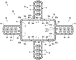
図1〜図9(図1A〜図1Dを含む)の図及び例に関して、同様の符号は、図面全体を通して同じ又は対応する構成要素を示し、図1に、送路22と、送路22に沿って推進可能な複数の搬送体24と、を含む、送路システム20を示す。送路システム20は、任意の適切な種類のシステムを含み得る。いくつかの実施形態では、送路システム20は、リニア同期モータ(LSM)ベースのシステムであることができ、同システムでは、電磁力(EMF)を使用して、送路22に沿った搬送体24の推進が容易となる。他の実施形態では、送路システムは、搬送体が個々のサーボモータなどにより他の何らかの様式で推進されるシステムであり得る。しかしながら、示された実施形態では、搬送体は、リニア同期モータ(LSM)ベースのシステムにより推進される。
With respect to the figures and examples of FIGS. 1A-9 (including FIGS. 1A-1D), similar reference numerals indicate the same or corresponding components throughout the drawing, in FIG. The
搬送体24のうちの1つが、図2に図示され、中央リブ30により互いに結合された上部26と、下部28と、を含むように示されている。一実施形態では、上側部分26及び下側部分28は、ファスナ32により取り外し可能に互いに結合され得る。上側部分26及び下側部分28は、中央リブ30により互いに離間していることができる。図3に示されているように、上側部分26は、中央リブ30に隣接し、下側部分28に面する摩耗面又は走行面34を含み得る。下側部分28は、送路22に沿った搬送体24のLSM推進を容易にする磁石36を含み得る。一実施形態では、磁石36は、S極で形成され、それぞれN極として形成された2つの端部の間に挟まれた中央磁石を有する磁石アレイであり得る。搬送体24は、送路システムに沿ったLSM推進を容易にするための各種の適切な代替構成のいずれかであり得ることを理解されたい。これらの代替構成のいくつかの例は、米国特許第6,011,508号、同第6,101,952号、同第6,499,701号、同第6,578,495号、同第6,781,524号、同第6,917,136号、同第6,983,701号、同第7,448,327号、同第7,458,454号、及び同第9,032,880号に記載されている。
One of the
容器38は、容器38に流動性材料を充填すること並びに/又は容器及び/若しくはその内容物に対して他の操作を行うことを容易にするために、送路22において容器38についてルート設定するために搬送体24に提供され得る。容器38は、流動性材料を受け入れ、分配するための少なくとも1つの開口部40を画定し得る。容器が開口部40を有すると言われる場合、複数の開口部を有する実施形態(例えば、別個のクロージャ又は単一のクロージャを有する多区画容器、プレスタブ(press-tab)通気口及びディスペンサ容器など)も含まれる。単一の搬送体上又は異なる搬送体上に、複数の容器が存在し得る。
The
送路システム22上に2つ以上の容器が存在する場合、容器24は、全て同じ種類若しくは幾何学的形態(すなわち、容器が同じサイズ、形状、外観のものであり、同じ容積を有する)でもよく、又は、容器のうちのいずれかが、サイズ、形状、外観若しくは容積のうちの1つ以上において他の容器と異なってもよい。容器の「形状」に言及する場合、これは、容器の外部形状を意味すると理解される。容器の「容積」に言及する場合、これは、容器の内部容積を意味すると理解される。複数の容器は、第1の、第2の、第3の容器などとして識別され得る。送路システム上において、任意の時点で、3つ以上の容器が異なってもよく、及び/又は、他の容器とは異なる流動性材料を保持してもよい。いくつかの実施形態では、任意の所定の時点において、送路システムに沿って配置されている、3、4、5、6、7、8、9、10又はそれ以上の異なる種類の容器又は異なる種類の容器群(これらは容器の種類及び/又はそこに含まれる流動性材料において互いに異なってもよい)が存在してもよい。
If there are two or more containers on the
容器から製品を分配することが望まれるまで、クロージャ42は、容器に結合して開口部40を閉じ得る(すなわち、クロージャにより開口部が「選択的に封止される」)。クロージャとしては、キャップ、例えば、スナップキャップ、ねじ付きスクリューキャップ、ヒンジ及び頂部若しくは移行スパウト(transition spout)などの複数の部品を含むキャップ、接着キャップ(例えば、スパウトを備えた一部の洗濯洗剤容器に使用されるもの)、計量機能を果たすキャップ、例えば、口腔リンスキャップ、ポンプ又はトリガ及びエアロゾルノズルが挙げられるが、これらに限定されない。クロージャは、形状、サイズ及び外観を有する。容器と同様に、クロージャは、全て同じ種類でもよく、又は、クロージャのいずれかが、形状、サイズ、若しくは外観のうちの1つ以上において他のクロージャと異なってもよい。複数のクロージャは、第1の、第2の、第3のクロージャなどとして識別され得る。
The
一実施形態では、図2に示されているように、容器38は、搬送体24の上側部分26により画定された真空ポート44を介して、搬送体24に取り外し可能に固定され得る。このような実施形態では、容器38が搬送体24の上側部分26に置かれたとき、1次ポート46において真空引きすることにより、真空ポート44において真空引きすることができる。容器38が真空ポート44上に設けられ、真空ポート46において真空引きされると、真空により、容器38が搬送体24に固定され得る。1次ポート46は、1次ポート46を真空ポート44から選択的に流体的に隔離するシュレーダーバルブ(図示せず)などのバルブを含むことができ、これにより、いったん容器38が真空引きされると、バルブにより、バルブがその後作動されるまで真空が解放されることが防止される。一実施形態では、上側部分26の上面48は、容器38と上面48との間の有効な封止を促進するエラストマー材料又は他の類似の材料で形成され得る。本明細書において、搬送体24の一部は、上側部分26として説明されているが、搬送体のこの部分は、容器の保持面を含み、必ずしも常に上向きである必要はないと理解されたい。保持面は、任意の適切な方向に向けることができる。この向きは、本明細書に記載された方法の適切な段階において、下向き(上下逆)又は横向きを含む。(当然、流動性材料を内部に有し、その開口部が封止されていない容器は、典型的には、上下逆の状態で搬送されないことになるが、空の容器又は閉じた容器は、上下逆又は横向きに搬送され得る。)
In one embodiment, as shown in FIG. 2, the
本明細書に記載された容器は、各種の構成のいずれかであることができ、各種の製品を保持するために、各種の業界にわたって使用することができると理解されたい。例えば、本明細書に記載された容器の任意の実施形態は、消費者製品業界及び工業製品業界にわたって使用されてもよく、ここで、上記容器は、流動性製品を収容する。容器は、1回又は複数回の充填操作で充填して、部分的又は完全な意図された充填の後に、最終製品の一部若しくは複数の成分又は全ての成分を収容してもよい。最終製品は、一部又は全部が流動可能(flowable)又は流動性でもよい。 It should be understood that the containers described herein can be in any of different configurations and can be used across different industries to hold different products. For example, any embodiment of the container described herein may be used across the consumer and industrial products industries, where the container houses a liquid product. The container may be filled with one or more filling operations to contain some or more or all of the components of the final product after partial or complete intended filling. The final product may be partially or wholly flowable or fluid.
最終製品の例としては、以下の製品のうちの任意のものが挙げられ、全体又は一部において、これらのいずれかは、本明細書に記載され又は当技術分野で公知の任意の実行可能な(workable)流動性製品形態をとることができる:ベビーケア製品(例えば、石鹸、シャンプー及びローション);人間又は動物の毛を洗浄、処理、美化、及び/又は装飾するための美容ケア製品(例えば、ヘアシャンプー、ヘアコンディショナー、毛髪染料、毛髪着色剤、毛髪補修製品、育毛製品、除毛製品、毛髪減少製品など);人間又は動物の皮膚を洗浄、処理、美化、及び/又は装飾するための美容ケア製品(例えば、石鹸、ボディウォッシュ、ボディスクラブ、洗顔料、収斂剤、日焼け止め、日焼け止めローション、リップバーム、化粧品、皮膚コンディショナー、コールドクリーム、皮膚保湿剤、制汗剤、デオドラントなど);人間又は動物の爪を洗浄、処理、美化、及び/又は装飾するための美容ケア製品(例えば、マニキュア、マニキュア落としなど);人間の顔の毛を洗浄、処理、美化、及び/又は装飾するための手入れ製品(例えば、剃毛製品、プリシェービング製品、アフターシェービング製品など);人間又は動物の口腔を洗浄、処理、美化、及び/又は装飾するためのヘルスケア製品(例えば、歯磨き粉、マウスウォッシュ、口臭消臭製品、歯垢防止製品、歯白化製品など);人間及び/又は動物の健康状態を処理するためのヘルスケア製品(例えば、薬、薬剤、医薬品、ビタミン、栄養剤、栄養補給品(カルシウム、繊維など)、咳止め製品、風邪薬、ロゼンジ、呼吸及び/又はアレルギー疾患の治療、痛み止め、睡眠薬、胃腸治療製品(胸焼け、胃腸のむかつき、下痢、過敏性腸症候群など)、浄化水、処理水など;動物の給餌及び/又は世話のためのペットケア製品(例えば、ペットフード、ペットビタミン、ペット薬剤、ペットチュー、ペット治療など);布地、布、及び/又は洗濯物を洗浄、調整、清涼化、及び/又は処理するための布地ケア製品(例えば、洗濯洗剤、布地コンディショナー、布地染料、布地漂白剤など);家庭用、商用、及び/又は産業用の食器ケア製品(例えば、手洗い、及び/又は機械洗浄用の食器用石鹸、及びすすぎ助剤);家庭用、商用、及び/又は産業用の洗浄、及び/又は脱臭製品(例えば、柔軟表面洗浄剤、硬質表面洗浄剤、ガラス洗浄剤、セラミックタイル洗浄剤、カーペット洗浄剤、木洗浄剤、マルチ表面洗浄剤、表面消毒剤、キッチン洗浄剤、風呂洗浄剤(例えば、シンク、トイレ、バスタブ、及び/又はシャワークリーナー)、装置洗浄製品、装置処理製品、車洗浄製品、車脱臭製品、空気洗浄剤、空気脱臭剤、空気殺菌剤など)、など。パーソナルケア製品としては、化粧品、ヘアケア、スキンケア及び口腔ケア製品、すなわち、ヒトにおける使用のためのシャンプー、石鹸、歯磨き粉が挙げられる。 Examples of final products include any of the following products, and in whole or in part, any of these is feasible as described herein or known in the art. (Workable) can take the form of fluid products: baby care products (eg soaps, shampoos and lotions); beauty care products for cleaning, treating, beautifying, and / or decorating human or animal hair (eg soaps, shampoos and lotions). , Hair shampoos, hair conditioners, hair dyes, hair colorants, hair repair products, hair growth products, hair removal products, hair reduction products, etc.); for cleaning, treating, beautifying, and / or decorating human or animal skin. Beauty care products (eg soaps, body washes, body scrubs, cleansers, astringents, sunscreens, sunscreen lotions, lip balms, cosmetics, skin conditioners, cold creams, skin moisturizers, antiperspirants, deodorants, etc.); Beauty care products for cleaning, treating, beautifying, and / or decorating human or animal nails (eg, manicure, manicure remover, etc.); for cleaning, treating, beautifying, and / or decorating human facial hair. Care products (eg, shaving products, pre-shaving products, after-shaving products, etc.); Healthcare products for cleaning, treating, beautifying, and / or decorating the human or animal oral cavity (eg, toothpaste, mouthwash, etc.) Deodorant products, anti-staining products, whitening products, etc.); Health care products for treating human and / or animal health (eg, drugs, drugs, pharmaceuticals, vitamins, nutritional supplements, nutritional supplements (eg, drugs, drugs, pharmaceuticals, vitamins, nutritional supplements, nutritional supplements) Calcium, fiber, etc.), cough products, cold remedies, lotions, treatment of respiratory and / or allergic diseases, pain relievers, sleeping pills, gastrointestinal treatment products (chest burn, gastrointestinal upset, diarrhea, irritable bowel syndrome, etc.), purified water , Treated water, etc .; Pet care products for feeding and / or caring for animals (eg, pet food, pet vitamins, pet drugs, pet chews, pet treatment, etc.); washing fabrics, cloths, and / or laundry, Fabric care products for conditioning, cooling, and / or processing (eg, laundry detergents, fabric conditioners, fabric dyes, fabric bleachers, etc.); household, commercial, and / or industrial tableware care products (eg, eg. Dishwashing lotions for hand and / or machine cleaning, and rinsing aids); household, commercial, and / or industrial cleaning and / or deodorant products (eg, soft surface cleaning agents, hard surface cleaning agents, etc.) Glass cleaning agent, ceramic tile cleaning Cleaners, carpet cleaners, wood cleaners, multi-surface cleaners, surface disinfectants, kitchen cleaners, bath cleaners (eg sinks, toilets, bathtubs, and / or shower cleaners), equipment cleaners, equipment treatment products , Car cleaning products, car deodorizing products, air cleaning agents, air deodorants, air disinfectants, etc.), etc. Personal care products include cosmetics, hair care, skin care and oral care products, namely shampoos, soaps and toothpastes for human use.
更なる例として、本明細書に記載されるような容器の任意の実施形態は、家庭、商業及び/又は工業、建物及び/又は敷地、建設及び/又は保守の更なる領域にわたって使用される製品又は製品要素を含んでもよい。更なる例として、本明細書に記載されるような容器の任意の実施形態は、食品及び飲料業界にわたって使用される製品又は製品要素を含み得る。更なる例として、本明細書に記載されるような容器の任意の実施形態は、医薬品業界にわたって使用される製品又は製品要素を含み得る。 As a further example, any embodiment of a container as described herein is a product used across additional areas of home, commercial and / or industry, building and / or site, construction and / or maintenance. Alternatively, it may include product elements. As a further example, any embodiment of a container as described herein may include a product or product element used throughout the food and beverage industry. As a further example, any embodiment of a container as described herein may include a product or product element used throughout the pharmaceutical industry.
容器(例えば、38)は、各種の適切な材料、例えば、ポリマー組成物などのいずれかで形成され得ることを理解されたい。ポリマー組成物は、製品及び製品包装に形成され(例えば、容器などの様々な物品に成形され、容器を形成するために互いに結合される1つ以上のフィルム片に成形され又は他の方法で成形され)得る。いくつかの場合(例えば、ボトルを形成するために)、この組成物は、押出ブロー成形又は射出成形され得る。典型的には、高密度ポリエチレン(HDPE)は押出ブロー成形され、ポリエチレンテレフタレート(PET)は射出延伸ブロー成形される。完全に組み立てられた容器は、容器、クロージャ、ノズル及び/又はハンドルが挙げられるがこれらに限定されない、1つ以上の要素を含み得る。 It should be understood that the container (eg, 38) can be made of any of a variety of suitable materials, such as polymer compositions. Polymer compositions are formed into products and product packaging (eg, molded into various articles such as containers, molded into one or more film pieces that are bonded together to form a container, or otherwise molded Be) get. In some cases (eg, to form bottles), this composition can be extruded blow molded or injection molded. Typically, high density polyethylene (HDPE) is extrusion blow molded and polyethylene terephthalate (PET) is injection stretch blow molded. Fully assembled containers may include one or more elements including, but not limited to, containers, closures, nozzles and / or handles.
搬送体24は、特定の種類の容器に適合するように構成され得る。このように、送路22に沿った異なる容器種の同時ルート設定を可能にするように、異なる搬送体種が、送路22に提供され得る。また、搬送体24は、容器を搬送することに限定されない。いくつかの場合には、搬送体24は、他の目的に使用され得る。同目的としては、原料をユニット操作ステーションに配送すること及び切替(changeover)工具などの工具を送路システムの周囲の様々な場所に配送することを挙げることができるが、これらに限定されない。例えば、搬送体は、加飾ユニット操作ステーションからラベルを取り外す工具を運ぶために使用されてもよい。
The
再度図1を参照して、送路22は、複数の直線部分50a、複数の湾曲部分50b及び複数の移行部分50cにより形成され得る。図4に、直線部分50aのうちの1つが図示されており、基部54aに結合している一対のレール52aを含むように示されている。基部54aは、走行面56aと、走行面56aの下に配置された複数の導電性推進コイル58aと、を含み得る。導電性推進コイルは、移動方向における送路22に沿った搬送体のルート設定を容易にする。各導電性推進コイルは、共通軸を画定し、この共通軸の周囲に配置された1つ以上の巻きを有する導体を含む。複数の導電性推進コイルのそれぞれの共通軸は、互いに実質的に平行であり、所望の移動方向に実質的に直交していてもよい。複数のコイル58aは、いくつかの実施形態では、プリント回路基板(PCB)であり得る、下にある基板60a上に実装され得る。複数のコイル58aは、送路22に沿って搬送体24を推進するための、動力用コイル(power coil)58aの通電を容易にし得る電源(図示せず)と電気的に結合させ得る。推進コイル58aは、送路システムに沿った搬送体の推進を容易にするために、搬送体の磁石の両側のうち少なくとも一方に配置されてもよい。制御システム62(図1)は、送路22に沿った搬送体24の推進を制御するために、コイル58aの通電を制御し得る。一実施形態では、各コイル58aは、「Hブリッジ」の出力に結合しているトランジスタ(例えば、MOSFET又はIGBT)に電気的に結合され得る。制御システム62は、各コイル58aにおける電流の量及び方向を制御するHブリッジの動作を通して、送路22に沿った各搬送体24の推進を制御し得る。ホール効果センサ(図示せず)は、送路22上の搬送体24により生成される磁界の検出を容易にするために、基部54aに沿って分布され得る。制御システム62は、ホール効果センサと電気接続して、搬送体24の様々な推進特性(例えば、速度、方向、位置)の選択的制御を容易にし得る。
With reference to FIG. 1 again, the
各レール52aは、上側部分64a及び側方部分66aを有することができ、これらは互いに共同して、端部から見たときにL字形を形成する。各レール52aは、側方部分66aで基部54aにファスナ68aにより結合している。各搬送体24が送路22上に提供されると、各レール52aの上側部分64aは、搬送体24の上側部分26の摩耗面34がレール52aの上側部分64aに乗ることができるように、搬送体24の上側部分26と下側部分28との間の空間内に延び得る。代替的な実施形態では、摩耗面は、摩耗面から延びるホイールを有することができ、ホイールは、レール52aの上側部分64a上を移動することができる。各レール52aの側方部分66aは、搬送体24の下側部分28の両側に沿って延び得る。送路22に沿った搬送体24の作動中、レール52aは、搬送体24を送路22に沿って磁気的に推進させるために十分に、走行面56aの上方に、搬送体24を浮かせた(suspend)状態での、走行面56aに沿った搬送体24の案内を容易にすることができる。
Each
ここから図5を参照して、湾曲部分50bのうちの1つが図示されており、これは、図4に図示された直線部分50aと多くの点で類似又は同じである。例えば、湾曲部分50bは、基部54bに結合している一対のレール52bを含み得る。基部54bは、走行面56bと、走行面56bの下に配置された複数のコイル(図示せず)と、を含み得る。しかしながら、湾曲部分50bは、送路22に沿った搬送体24の方向転換を容易にするために、約90度、角度が付けられ得る。
From here, with reference to FIG. 5, one of the
ここから図6を参照して、移行部分50cのうちの1つが図示されており、これは、図4に図示された直線部分50aと多くの点で類似又は同じである。例えば、移行部分50cは、基部54cと結合している複数のレール52cを含み得る。基部54cは、走行面56cと、走行面56cの下に配置された複数のコイル(図示せず)と、を含み得る。しかしながら、移行部分50cは、直線部分70cと、異なる方向における搬送体24のルート設定を容易にする角度付き部分72cと、を有し得る。一実施形態では、移行部分50cは、後退位置(図6に示す)と伸長位置(図示せず)との間で旋回可能なフリッパー部材74を含み得る。フリッパー部材74が後退位置にあるとき、通過する搬送体24は、移行部分50cの直線部分70cに沿って移動することになる。フリッパー部材74が伸長位置にあるとき、通過する搬送体24は、直線部分70cから角度付き部分72cにルート設定されることになる。制御システム62は、フリッパー部材74と電気的に接続して、直線部分70c又は角度付き部分72cのいずれかへ、通過する搬送体24をルート設定する、選択的制御を容易にする。直線部分70cと角度付き部分72cとの間の搬送体の選択的ルート設定を容易にするために、各種の適切な代替的な入口スイッチ及び/又は出口スイッチのいずれかが利用され得ることを理解されたい。これらの代替構成のいくつかの例は、米国特許第9,032,880号及び米国特許出願公開第2007/0044676号に記載されている。
From here, with reference to FIG. 6, one of the
再度図1を参照して、送路22は、1次運送部76と、1次運送部76の周囲に設けられ、1次運送部76から延びる少なくとも1つの(代替的には複数の)2次運送部78と、を含み得る。1次運送部76は、搬送体24のための1次経路P1を画定し得る。2次運送部78はそれぞれ、入口位置80及び出口位置82において1次経路P1と交差する搬送体24のための2次経路P2を画定し得る。搬送体24は、関連する入口位置80及び出口位置82のそれぞれにおいて、2次運送部78それぞれに出入りし得る。搬送体24は、1次運送部76及び2次運送部78を時計回り又は反時計回りに移動し得る。いくつかの実施形態では、搬送体24のいくつかが時計回りに移動し、搬送体のいくつかがそのルートの一部分について反時計回りに同時に移動し又はその逆も可能であるが、反対方向の移動が搬送体間の衝突をもたらさないように注意しなければならない。
With reference to FIG. 1 again, the
2次運送部78それぞれには、それに沿って、「ユニット操作ステーション」の上記定義(並びにそこに含まれる変換及び検査の定義)に記載された任意の種類のユニット操作ステーションのうち、1つ以上のユニット操作ステーションが配置され得る。任意の適切な数のユニット操作ステーションが存在し得る。一般的には、2つ以上のユニット操作ステーション(例えば、2、3、4、5、...最大100又はそれ以上)が存在することになる。ユニット操作ステーションは、2次運送部78に沿って任意の適切な構成であってもよい。ユニット操作ステーションは、2次運送部の1つ以上に沿った単一のユニット操作ステーション又は2次運送部の1つ以上に沿ったユニット操作ステーション群によって、構成され得る。
For each of the
図1に、2次運送部78上のユニット操作ステーションの構成の1つの非限定的な実施形態を示す。図1に示された実施形態において、2次運送部78はそれぞれ、複数の容器載荷ステーション84、複数の組み合わされた充填/キャッピングステーション86、複数の加飾ステーション88又は複数の脱荷ステーション90(例えば、まとめて「ユニット操作ステーション」)のうちの1つを含む。この実施形態では、特定の2次運送部78に位置するユニット操作ステーション84、86、88、90はそれぞれ、並列に配列された異なるユニット運送区間91に沿って配置され得る。搬送体24は、複数の容器38内への流動性材料のボトル詰めを容易にするために、2次運送部78の間で選択的にルート設定され得る。
FIG. 1 shows one non-limiting embodiment of the configuration of the unit operating station on the
例えば、搬送体24が空である(すなわち、容器38がない)場合、搬送体24は、まず、空の容器38が搬送体24に載せられる容器載荷ステーション84のうちの1つへとルート設定され得る。ついで、搬送体24により、空の容器38は、流動性材料が充填され、クロージャ40のうちの1つにより封止される充填/キャッピングステーション86のうちの1つにルート設定され得る。ついで、搬送体24により、容器38は、加飾ステーション88のうちの1つにルート設定されて、加飾を受けることができ、ついで、容器38は、包装を行うために、充填された容器38が搬送体24から取り外され得る脱荷ステーション90のうちの1つへとルート設定され得る。
For example, if the
図1に図示されているより、送路22上にかなり多くの搬送体24が存在し得ることを理解されたい。また、ユニット操作ステーション84、86、88、90よりかなり多くの搬送体24も存在し得る。搬送体24はそれぞれ、容器38の少なくともいくつかのユニット操作ステーション84、86、88、90のうちの異なるものへの同時配送を容易にするために、送路22に沿って独立してルート設定可能である。図1に示された実施形態におけるユニット運送区間91は、はしごにおける横木の外観を有し得る。ユニット運送区間91は、複数の搬送体24を同時に収容するために十分な長さを有し得る。異なるユニット運送区間91は、同じ長さ又は代替的に異なる長さを有し得る。このように、複数の搬送体24は、ユニット運送区間91上で待機して、関連するユニット操作ステーション84、86、88、90への配送を待つことができる。当然、搬送体は、はしご様構造のサイドレール上でも待機し得るが、いくつかの場合には、これにより、搬送体が、他の搬送体が下流のユニット運送区間91に到達するのを妨害してしまうおそれがある。
It should be understood that there can be significantly
搬送体24がユニット操作ステーション84、86、88、90のうちの1つに配置されていない場合、少なくとも1つ(又はそれ以上、例えば、2、3、4、5、...最大100又はそれ以上)の搬送体24は、1次運送部76の周りを連続的に回っていることができるため、2次運送部78に進路を変えられるまで待機している間に、2次運送部78を迂回し得る。1次経路P1は、搬送体24の循環を容易にするために、閉ループの形態にあり得る。1次経路P1は、巡回的(circuital)又は連続的として記載されてもよい。1次経路P1は、任意の適切な構成のものであり得る。1次経路P1に適した構成としては、円形経路、楕円形経路又は直線部分と曲線部分との両方を含む経路が挙げられるが、これらに限定されない。後者の種類の経路の非限定的な例としては、レース送路構成経路、(図1に示された)丸みを帯びた角を有する概して長方形の経路及び他の閉ループ経路が挙げられる。当然、1次経路P1は、そこから2次経路P2に進路を変えられる、容器を載せた搬送体用の入口部分及び出口部分を有するため、1次経路に入る又はそこから出る搬送体に対して閉じられていない。
If the
いくつかの場合には、図1Aに示されているように、1次経路P1は、1次運送部76の主閉ループの内側に配置され、主閉ループの部分間に経路を形成する1つ以上のサブループ77を更に含んでもよい。サブループ77は、主閉ループ76の対向する部分の間に経路を形成してもよい。しかしながら、サブループ77は、代替的に、主閉ループ76の対向しない部分の間に経路を形成してもよい。当然、サブループへの入口部分及び出口部分が存在する。サブループ77は、容器を載せた搬送体のうちの少なくともいくつかが、完全に1次経路P1の閉ループの周りを移動することなく再循環するための経路を提供する。
In some cases, as shown in FIG. 1A, the primary path P1 is located inside the main closed loop of the
任意の適切な数の2次経路P2(例えば、1、2、3、4、5、...最大100又はそれ以上)が存在し得る。いくつかの場合には、2つの横木を有する、はしご構成(以下に記載)を有する単一の2次経路で十分であり得る。一般的には、2つ以上の2次経路(少なくとも1つは充填用、1つは脱荷用)が存在することになる。2つ以上の2次経路P2が存在する場合、これらは、第1の、第2の、第3の2次経路などと呼ばれ得る。同様に、2次経路用の入口位置は、第1の2次経路用の第1の入口位置及び出口位置、第2の2次経路用の第2の入口位置及び出口位置などと呼ばれてもよい。図1に示されているように、異なる2次経路78は全て、それに沿って配置された単一の種類のユニット操作ステーションを有するが、これは必須ではない。他の実施形態では、1つ以上の異なる2次経路78に沿って配置されるユニット操作ステーションの種類は異なってもよい。加えて、いくつかの場合には、単一の種類のユニット操作ステーションが、2つ以上の2次経路に沿って配置され得る。
There can be any suitable number of secondary pathways P2 (eg, 1, 2, 3, 4, 5, ... up to 100 or more). In some cases, a single secondary route with a ladder configuration (described below) with two crossbars may be sufficient. Generally, there will be two or more secondary pathways (at least one for filling and one for unloading). If there are two or more secondary paths P2, they may be referred to as first, second, third secondary paths, and the like. Similarly, the inlet position for the secondary route is called the first inlet position and exit position for the first secondary route, the second inlet position and exit position for the second secondary route, and the like. May be good. As shown in FIG. 1, all different
2次経路P2は、任意の適切な構成のものであり得る。2次経路P2は、互いに同じ構成のものでもよいし、又は、異なる構成のものでもよい。2つ以上の2次経路P2が存在する場合、2次経路のうちの2つは、同じ構成を有してもよく、少なくとも1つの2次経路は、異なる構成を有してもよい。2次経路P2に適した構成としては、直線経路、曲線経路又は直線部分と曲線部分との両方を含む経路が挙げられるが、これらに限定されない。 The secondary path P2 can be of any suitable configuration. The secondary paths P2 may have the same configuration or different configurations. When two or more secondary routes P2 are present, two of the secondary routes may have the same configuration and at least one secondary route may have a different configuration. A suitable configuration for the secondary path P2 includes, but is not limited to, a straight path, a curved path, or a path including both a straight portion and a curved portion.
可能な2次運送部(及び2次経路)の構成は、事実上無限にある。図1A〜図1Dに、これらのうちのいくつかを示す。直線経路の一例は、図1Bに示された2次運送部78Aのような経路であり、同図において、2次経路P2は、組み合わせられた入口/出口位置で1次経路P1に結合している直線区間を形成する。容器を載せた搬送体は、1次経路P1から離れて、このような2次経路P2に入ることができ、その後、直線2次経路P2に沿って、その移動を再び辿って、1次経路P1に再び入ることができる。直線部分と曲線部分との両方を含む2次経路の非限定的な例としては、(図1に示された)丸みを帯びた角を有する概して長方形の経路が挙げられる。このような2次経路は、平面図ではしご構成を有するように見え得る。はしごにおいて任意の適切な数(例えば、1、2、3、4、5又はそれ以上)の横木が存在し得る。2次経路の入口部分80及び出口位置82は、図1に示されているように、離間していてもよく、又は、他の場合には、図1Cにおける2次運送部78Eに示されているように、同じ(1次経路上で離間していない)でもよい。
The possible configurations of secondary transport units (and secondary routes) are virtually endless. Some of these are shown in FIGS. 1A-1D. An example of a linear route is a route such as the
2次経路P2は、1次経路P1に対して任意の適切な位置にあってもよい。1つ以上の2次経路P2は、図1に示されているように、1次経路P1の閉ループの外側で外向きに延びてもよい。他の場合には、図1Cに示された2次運送部78Fの場合におけるように、1つ以上の2次経路P2が、1次経路P1の閉ループの内側に位置してもよい。他の場合には、図1Cに示された2次運送部78G及び78Hの場合におけるように、78Hなどの、2次経路の1つ以上の部分は、2次運送部の外側に延びてもよい(及び所望される場合には、その任意の側又は部分からはしごを形成する)。更に、図1に示された実施形態では、1次経路P1は、丸みを帯びた角を有する4つの辺を有する概して長方形の経路であり、1次経路P1の各辺に2次経路P2の分岐が1つ存在するが、他の場合には、異なる構成が存在してもよい。例えば、図1Aに示されているように、1次経路P1の1つ以上の辺から延びる2つ以上の2次経路P2が存在し得る。いくつかの場合には、1次経路P1の1つ以上の辺は、そこから延びる2次経路P2を有していなくてもよい。
The secondary path P2 may be at any suitable position with respect to the primary path P1. One or more secondary paths P2 may extend outward outside the closed loop of the primary path P1, as shown in FIG. In other cases, one or more secondary paths P2 may be located inside the closed loop of the primary path P1, as in the case of the
図1Aには、2次経路78(図1Aの右上部分)に、場合により、戻りループ79を設け得ることが示されている。この2次経路78は、上側横木と、下側横木と、を有するはしごの形態で示されている。この場合には、上側横木は、搬送体が1次経路76上での搬送体の移動と同じ方向(例えば、時計回り)に移動し得る従来の横木であり得る。別の横木、例えば、下側横木は、戻りループ79を提供することができ、戻りループ79において、搬送体は、矢印の方向にはしごの入口脚に戻ることができる。これにより、搬送体は、必要に応じて、この特定の2次経路上の2つ以上のユニット操作ステーションを通して送られ得る。また、これにより、搬送体は、必要に応じて、この特定の2次経路上で2回以上、1つ以上のユニット操作ステーションを通して送られ得る。
FIG. 1A shows that the secondary path 78 (upper right portion of FIG. 1A) may optionally be provided with a
図1Bに、いくつかの他の2次経路構成を示す。2次経路78Bは、2次経路78Aと機能が類似しているが、曲線構成を有する2次経路の例である。2次経路78Cは、搬送体が入口点の下流にある出口点に運送されるのを可能にする追加の脚を含む。2次経路78C上の搬送体は、2次経路の第1の脚部内に「ヘッドファースト」で移動することとなり、ついで、方向を反転し、この2次経路の第2の脚部に沿って移動するとき、「テールファースト」で移動することになる。2次経路78Dは、別の追加の(3番目の)脚部(2次経路78Cのものを越える)を含み、これにより、搬送体は、再び向きを変え、1次経路76に戻る際に、この第3の脚部に沿ってヘッドファーストで移動し得る。
FIG. 1B shows some other secondary route configurations. The
図1Dは、別の2次経路構成を示す。図1Dに示されているように、任意の適切な様式で並列又は直列にネスト又はカスケードされた複数の2次経路が存在することが可能である。 FIG. 1D shows another secondary route configuration. As shown in FIG. 1D, it is possible that there may be multiple secondary paths nested or cascaded in parallel or in series in any suitable manner.
1次運送部76の周りを搬送体24が循環することにより、送路22上の渋滞を緩和することができ、送路システム20のスループットを高めることができる。例えば、搬送体24が最終製品を製造する過程におけるシーケンスの次のユニット操作ステーション84、86、88、90へとルート設定されるようにスケジューリングされており、かつ、そのユニット操作ステーション84、86、88、90が占有されている場合(すなわち、ユニット操作ステーション84、86、88、90を占有する他の搬送体24により)、搬送体24は、1次運送部76の周りを(すなわち、待機パターンで)循環し得る。スケジューリングされたユニット操作ステーション84、86、88、90が搬送体を受け入れる準備ができると、ついで、搬送体24は、スケジューリングされたユニット操作ステーション84、86、88、90の適切な運送区間91に進路を変えられ得る。
By circulating the
1つ以上の種類のユニット操作ステーションが、1次運送部76に沿って位置することが可能である。しかしながら、1次運送部76上での渋滞を緩和し、1つ以上の搬送体24が1次経路P1に沿って連続的に循環するのを可能にするために、1次運送部76は、いくつか又は全てのユニット操作ステーション(すなわち、84、86、88、90)を欠くことができ、代わりに、ユニット操作ステーションは、上記のように、2次運送部78に位置することができる。代替的に、1次運送部76は、それに沿って位置する高速サイクルステーションのみを有してもよい。したがって、搬送体24は、ユニット操作ステーション84、86、88、90により行われる操作を受けるために、1次運送部76から進路を変えられるため、1次運送部76上での交通の流れを妨害しない。(当然、他の実施形態では、1つ以上のユニット操作ステーションが、1次運送部76に沿って位置することができ、他のユニット操作ステーションが、2次運送部78上に位置することができる。)
One or more types of unit operating stations can be located along the
送路システム20をこの様式で作動させることにより、従来の容器充填構成より効率的に充填容器を製造し得る。以下に更に詳細に記載されるように、制御システム62は、送路22の動作、搬送体24それぞれのルート設定及びユニット操作ステーション84、86、88、90それぞれの動作を調整して、最終製品のオーダーを効率的かつ効果的に満たし得る。このため、制御システムは、送路22、搬送体24及びユニット操作ステーション84、86、88、90と通信している。これらの構成要素の動作の調整としては、例えば、搬送体の識別、搬送体のスケジューリング、衝突回避、ルート選択、停止報告などを挙げることができる。
By operating the
図1に示された実施形態におけるユニット操作ステーション84、86、88、90はそれぞれ、ここからより完全に説明されることになる。容器載荷ステーション(又は単に「載荷ステーション」)84は、空の容器(例えば、38)及び/又はそのクロージャを、容器載荷ステーション84に位置する搬送体24上に載せることを容易にするように構成され得る。容器載荷ステーション84は、容器及び/又はクロージャを搬送体へ載せることを容易にする、各種の自動化及び/又は手動構成のいずれかを含み得ることを理解されたい。載荷は、例えば、任意選択的なゲートを有する重力供給シュート又は機械的動作装置により、手動で、静的に行い得る。適切な機械動作装置としては、独立作動式自動アーム、空圧アーム、ロボット、輸送ホイール及び他の機械的運動要素が挙げられるが、これらに限定されない。一実施形態では、容器載荷ステーション84はそれぞれ、容器38及び/又はクロージャを保管領域から取り出し、容器38及び/又はクロージャを搬送体24上に置くロボットアーム(図示せず)を含み得る。容器38及び/又はクロージャの把持を容易にするために、各ロボットアームは、ロボット下顎(robotic mandible)、吸引端又は容器38及び/若しくはクロージャの把持を可能にする各種の適切な追加又は代替構成のいずれかを有し得る。容器38及び/又はクロージャが搬送体24の定位置に配置されると、真空ライン(図示せず)が1次ポート46(図2)に挿入されて、真空ポート44において真空引きすることにより、容器38及び/又はクロージャを搬送体24に一時的に固定し得る。ついで、真空ラインは、1次ポート46から取り外されることにより、容器38及び/又はクロージャの真空を維持するために、関連する弁(図示せず)を閉じ得る。
The
充填ユニット操作ステーションは、流動性材料を少なくともいくつかの容器に分配するために使用される。充填ユニット操作ステーションは、容器を任意の特定のレベル(例えば、「満杯」レベル)に充填する必要はない。充填ユニット操作ステーションは、任意の適切な流動性材料を容器に分配し得る。いくつかの場合には、充填ユニット操作ステーションは、最終製品の全ての成分を含む組成物を容器に分配し得る。代替的には、充填ユニット操作ステーションは、ベース組成物を容器に分配することができ、最終製品を形成するために、容器は、そこに添加される他の成分を有する別の充填ユニット操作ステーションに送られ得る。このため、いくつかの充填ユニット操作ステーションは、最終製品組成物の一部分のみを分配してもよい。このような部分としては、水、シリコーン(例えば、コンディショニング剤として使用するためのものなど)、染料、芳香剤、香料、漂白剤、消泡剤、界面活性剤、構造化剤などが挙げられるが、これらに限定されない。成分が別々に添加される場合、それらは、任意の適切なユニット操作ステーションで混合され得る。 The filling unit operating station is used to distribute the fluid material into at least several containers. The filling unit operating station does not need to fill the container to any particular level (eg, "full" level). The filling unit operating station may dispense any suitable fluid material to the container. In some cases, the filling unit operating station may dispense a composition containing all the ingredients of the final product into a container. Alternatively, the filling unit operating station can distribute the base composition to the container, and in order to form the final product, the container has another filling unit operating station with other ingredients added therein. Can be sent to. For this reason, some filling unit operating stations may only dispense a portion of the final product composition. Such parts include water, silicones (eg, for use as conditioning agents), dyes, fragrances, fragrances, bleaches, defoamers, surfactants, structuring agents and the like. , Not limited to these. If the ingredients are added separately, they can be mixed at any suitable unit operating station.
加えて、いくつかの充填ユニット操作ステーションは、1種類の流動性材料のみを分配するように構成されてもよいが、充填ユニット操作ステーションは、1種類の流動性材料のみ(例えば、1色の染料など)を分配することに限定されない。いくつかの場合には、充填ユニット操作ステーションの1つ以上は、異なる成分を(例えば、異なる流動性材料サプライ及びノズルから)分配するように構成され得る。例えば、同じ充填ユニット操作ステーションは、緑色の最終組成物、青色の最終組成物及び赤色の最終組成物を分配することができ、又は、緑色染料、青色染料及び赤色染料を分配することができる。このような場合には、少なくとも2つの異なる種類の容器(例えば、第1の、第2の、第3の容器など)は、同じ流動性材料分配ユニット操作ステーションから、又は、同じ種類の流動性材料分配ユニット操作ステーションから、最終組成物のための1つ以上(又は全て)の成分を受け取ってもよい。 In addition, some filling unit operating stations may be configured to distribute only one type of fluid material, whereas the filling unit operating station may be configured to distribute only one type of fluid material (eg, one color). It is not limited to distributing dyes, etc.). In some cases, one or more of the filling unit operating stations may be configured to distribute different components (eg, from different fluid material supplies and nozzles). For example, the same filling unit operating station can dispense a green final composition, a blue final composition and a red final composition, or can dispense a green dye, a blue dye and a red dye. In such cases, at least two different types of containers (eg, first, second, third containers, etc.) may be from the same fluidity material distribution unit operating station or of the same type of fluidity. One or more (or all) components for the final composition may be received from the material distribution unit operating station.
したがって、充填ユニット操作ステーションは、流動性材料を容器に分配するための複数の独立制御可能なノズルを含み得る。このような独立制御可能なノズルは、多数の異なる形態をとってもよい。いくつかの場合には、単一のノズルを使用して、2つ以上の異なる流動性材料を分配し得る。他の場合には、充填ユニット操作ステーションは、複数のノズルを含むノズルバンクを含んでもよく、同ノズルはそれぞれ、同じか又は異なる流動性材料を分配するように構成されてもよい。更に他の場合には、1つ以上のノズルは、異なる高さの容器に適合するように、上方及び下方に移動可能であり得る。 Therefore, the filling unit operating station may include multiple independently controllable nozzles for distributing the fluid material to the container. Such independently controllable nozzles may take many different forms. In some cases, a single nozzle may be used to dispense two or more different fluid materials. In other cases, the filling unit operating station may include a nozzle bank containing a plurality of nozzles, each of which may be configured to distribute the same or different fluid material. In yet other cases, the one or more nozzles may be movable up and down to fit containers of different heights.
組み合わせられた充填/キャッピングステーション86は、流動性材料を容器38に分配し、いったん充填されると、容器38にクロージャを適用するように構成され得る。図7に、組み合わせられた充填/キャッピングステーション86の一例が図示されており、充填部分92と、キャッピング部分94と、を含むように示されている。充填部分92は、後退位置(図7)と伸長位置(図示せず)との間を垂直に移動し得る充填アーム96を含み得る。キャッピング部分94は、後退位置(図示せず)とキャッピング位置(図7)との間を垂直に移動し得るキャッピングアーム98を含み得る。容器38の充填を開始するために、空の容器38が充填アーム96の下に位置する状態で、搬送体24が、充填部分92へとルート設定され得る。ついで、充填アーム96は、後退位置から伸長位置まで移動して、容器38の開口部40と係合し得る。ついで、充填アーム96は、流動性材料を容器38に分配し得る。流動性材料が分配されると、充填アーム96は、流体の分配を停止することができ、後退位置に戻ることができる。ついで、搬送体24は、クロージャ42がキャッピングアーム98の下に位置した状態で、キャッピング部分94へとルート設定され得る。ついで、キャッピングアーム98は、クロージャ42まで延び、クロージャ42を把持し、ついで、後退位置に戻り得る。ついで、搬送体24は、容器38の開口部40をキャッピングアーム98の下に移動させ得る。キャッピングアーム98は、キャッピング位置まで移動することができ、クロージャ42を容器38にねじ込むか、又は、他の方法で取り付けることができる。クロージャ42は、内容物にアクセスするために、消費者により取り外し可能又は開放可能でもよい。
The combined filling /
いくつかの実施形態では、クロージャ42は、容器40上で運送されてもよい。このような実施形態では、搬送体24が充填/キャッピングステーション86に到着すると、搬送体24は、まず、キャッピング部分94へとルート設定され得る。キャッピングアーム98は、クロージャ42を容器38から取り外すことができ、クロージャ42を保持しながら、後退位置に移動することができる。ついで、容器38を流体で充填するために、搬送体24は、充填部分92へとルート設定され得る。容器が充填されると、搬送体24は、キャッピングステーション94に戻ることができ、ここで、キャッピングアーム98は、クロージャ42を容器38に固定する。他の実施形態では、クロージャ42は、容器上ではないが、容器38と同一搬送体上にある状態で(例えば、同一搬送体上であるが、容器に隣接する)、充填/キャッピングステーション86に運送され得る。他の実施形態では、クロージャ42は、容器38を運送している搬送体とは異なる搬送体(例えば、別個の搬送体)上にある状態で、充填/キャッピングステーション86に運送され得る。クロージャが搬送体上で運送されるとき、クロージャは、真空により(又は他の何らかの適切な様式で)保持され、必要に応じて、最終製品ユニット操作ステーションのいずれかに送られ得る。例えば、クロージャ42を、クロージャを加飾するための加飾ステーションに送ることが望ましい場合がある。更に他の実施形態では、クロージャ42は、空の容器38と共に運送されなくてもよいが、代わりに、キャッピング部分94に到達したとき(すなわち、容器38が流動性材料で充填された後)に、容器38に提供され得る。充填/キャッピングステーション86は、容器の充填及びキャッピングを容易にする、各種の追加又は代替の自動及び/又は手動構成のいずれかを含み得ることを理解されたい。
In some embodiments, the
図8に、2次運送部1078の代替的な実施形態が図示されており、図1及び図7に示され、上記された充填/キャッピングステーション86と多くの点で類似又は同じである、複数の充填/キャッピングステーション1086を含むように示されている。しかしながら、充填/キャッピングステーション1086は、送路(例えば、22)の1次運送部1076に沿って直列に配置された、異なるユニット運送区間1091に沿って配置され得る。他のユニット操作ステーションは、追加的に又は代替的に、直列に配置された、異なるユニット運送区間1091に沿って配置され得ることを理解されたい。
An alternative embodiment of the
加飾ステーション88は、容器38のラベリング、印刷又は他の方法での加飾を容易にするように構成され得る(また、場合により、そのクロージャに対しても同じことを行う)。一実施形態では、加飾ステーション88のうち少なくとも1つは、容器38に適用するためのラベルを印刷するプリンタ(図示せず)を含み得る。このような実施形態では、プリンタは、バッキング基材上にあるステッカー上にラベルを印刷し得る。スプーリングアセンブリ(図示せず)は、ステッカー及びバッキング基材を受け入れ得る。容器38を運ぶ搬送体24がスプーリングアセンブリを通過するとき、スプーリングアセンブリを通過する容器38の移動により、容器38へのステッカーの適用が容易になり得る。他の実施形態では、プリンタは、転写コンポーネント上にインクを印刷することができ、接着剤が、インク上に適用されて、複合構造を形成することができる。ついで、インクと接着剤の複合構造は、(別個のステッカーを使用せずに)ラベル又は装飾を形成するために、転写コンポーネントから容器上へ転写され得る。このような構成は、ラベルの「オンデマンド」印刷を容易にすることができ、これにより、異なるラベルが、搬送体24により運ばれる異なる種類の容器38及び/又は流体に対して印刷され得る。これらのラベルは、例えば、文字、グラフィックス、ブランディング、成分、SKU情報又は容器38が販売のために展示されるときの他の視覚的要素などの様々な種類の装飾及び製品情報を含み得る。必要に応じて、容器は、小売業者又は個々の消費者からのオーダーに対して及び/又はそれに応答して、個別化させる(personalize)こともできる。
The
脱荷ステーション90は、搬送体24からの充填済み容器38の取り出しを容易にするように構成され得る。一実施形態では、脱荷ステーション90はそれぞれ、包装(例えば、店舗ディスプレイ又は出荷容器)を行うために、容器38を各搬送体24から回収するロボットアーム(図示せず)を含み得る。容器38の把持を容易にするために、ロボットアームは、ロボット下顎、吸引端又は容器38の把持を可能にする各種の適切な追加又は代替構成のいずれかを有し得る。容器38が搬送体24から取り外されると、搬送体24は、充填のための別の空の容器38を受け入れるために、容器載荷ステーション84へとルート設定され得る。脱荷ステーション90は、容器の包装への脱荷を容易にする各種の追加又は代替の自動及び/又は手動構成のいずれかを含み得ることを理解されたい。
The unloading
いくつかの実施形態では、容器38は、販売業者で販売するために容器38を陳列するように設計された包装に提供され得る。このような包装では、容器38は、個々に販売するために提供されることができ、又は、共に商取引の物品を形成する1つ以上の他の容器又は製品と共に包装されることができる。容器38は、2次包装のある、又は、2次包装のない1次包装として販売のために提供され得る。容器38は、店舗の棚上に横にするか若しくは直立した状態、販売促進陳列(merchandising display)で提示した状態、陳列ハンガに掛けた状態、又は、陳列ラック若しくは自動販売機内に装填した状態で、販売用に陳列されるように構成され得る。容器38が流動性製品用である場合、容器38は、これらの方法のいずれか又は意図した技術分野で公知の他の任意の方法で、問題なく陳列可能な構造で構成され得る。いくつかの実施形態では、脱荷ステーション90は、従来の操作で多くの場合必要とされるような容器38の手動操作を必要とせずに、同じ包装内で異なる種類の容器及び/又は流動性材料の包装(「バンドル化(bundling)」)を容易にし得る。
In some embodiments, the
送路システム20は、任意の適切な数及び/又は種類の検査ステーションを含み得る。例えば、図1において、送路システム20は、通過する容器38をスキャンするようにそれぞれ構成されている第1のスキャナ100及び第2のスキャナ102を含み得る。第1のスキャナ100は、入口位置80のうちの1つと充填/キャッピングステーション86との間に位置することができ、通過する各搬送体24をスキャンして、容器38が存在するかどうかを判定することができる。第2のスキャナ102は、加飾ステーション88と脱荷ステーション90との間に位置することができ、通過する各搬送体24をスキャンして、その上に配置された容器38が脱荷ステーション90による包装の準備ができているかどうかを判定することができる。
The
容器38が(例えば、内容物及び/又は容器の欠陥により)脱荷ステーションのうちの1つによる包装の準備ができていない場合、容器は、その目的地の脱荷ステーションで降ろされ得る。他の場合には、容器を有する搬送体は、代替的な脱荷ステーションに送られ得る。目的地又は代替の脱荷ステーションでは、下記動作のうちの1つ以上を行い得る:容器及び/若しくはその内容物の欠陥を修復することができ;容器を空にしてリサイクルすることができ、並びに/又は、容器及び/若しくはその内容物を廃棄し得る。容器は、脱荷ステーションから降ろされ、搬送体は、新たなルート割当ての準備が整う。
If
第1のスキャナ100及び第2のスキャナ102は、搬送体24及び/又は容器38から情報を取得するための各種のスキャナのいずれか、例えば、赤外線スキャナであり得る。第1のスキャナ100及び第2のスキャナ102は、例えば、QRコード又はUPCバーコードなどの、容器38からの各種のデータの読取りを容易にするようにも構成され得る。
The
送路システム20は、異なる種類の流動性材料を様々な種類の異なる容器に同時に分配することを容易にし得ることを理解されたい。(当然、異なる容器への分配の開始時間及び終了時間は、正確に一致してもよいが、必ずしも一致する必要はない。異なる容器への分配は、時間的に少なくとも部分的にのみ重複してもよい)
It should be understood that the
加えて、いくつかの場合には、1つ以上の容器は、最終製品を製造するために使用される流動性材料が充填されなくてもよい。例えば、1つ以上の容器は、充填ユニット操作ステーションにおいて1つ以上のノズルから洗浄又はフラッシュされる流動性材料を受容するために使用されてもよく、この流動性材料は、その後、廃棄又はリサイクルされ得る。 In addition, in some cases, the one or more containers may not be filled with the fluid material used to make the final product. For example, one or more containers may be used to receive fluid material that is washed or flushed from one or more nozzles at the filling unit operating station, which fluid material is then discarded or recycled. Can be done.
以下でより詳細に説明されることになるように、各搬送体24に提供される特定の容器種及び流動性材料は、特定の製造スケジュールを満たすように制御システム62により選択されることができ、各搬送体24は、容器38の載荷及び充填を容易にするために、ユニット操作ステーション(例えば、84、86、88、90)間のユニークなルートに沿って独立かつ同時にルート設定され得る。各搬送体24のためのユニークなルートは、少なくとも部分的に、搬送体の種類(すなわち、搬送体24が適合するように構成された1つ以上の容器の種類)、他の搬送体24のために選択されたユニークなルート、及び/又は、例えば、脱荷ステーション90が包装のために必要とする最終製品の種類に基づいて、制御システム62により選択され得る。送路システム20は、従来の構成より効率的かつ効果的に、異なる種類の容器に異なる種類の流体を充填するのを容易にし得ることを理解されたい。従来の構成、例えば、リニアモータ充填ラインは、典型的に、一度に1種類の流体を1種類の容器に充填するのを可能にするのみである。したがって、多くの場合、個別のシステムが、製造される各容器及び流体に対して必要とされ、これは、高価で時間がかかるおそれがある。加えて、これらのシステムを異なる容器及び/又は流体を使用するように変換することも、高価で時間がかかるおそれがある。したがって、送路システム20は、これらの従来の構成より費用がかからず、時間がかからない様式で、異なる種類の充填済み容器の製造を可能にする解決策であり得る。
As will be described in more detail below, the particular container type and fluid material provided for each
異なるユニット操作ステーションで行われる操作は、同じ時間量を要する可能性があるが、そうでない場合が多いと理解されたい。これらの期間は、第1の持続時間、第2の持続時間、第3の持続時間などと呼ばれてもよい。第1の、第2の、第3の持続時間などは同じであることができ、又は、ある持続時間が他の持続時間より長くてもよい。例えば、いくつかのユニット操作ステーションは、他のユニット操作ステーションと比較して比較的に速い操作を行い;いくつかのユニット操作ステーションは、比較的遅くてもよく、いくつかのユニット操作ステーションは、比較的速いいくつかの操作及びより遅いいくつかの操作を行ってもよい(例えば、1つの成分を分配することができ、また、完全な組成物を含むより多くの量を分配することができる充填ステーションなど)。したがって、図1には、同数の充填/キャッピングユニット操作ステーション及び加飾ステーションが示されているが、これは必須ではない。このため、このシステムは、例えば、より低速なユニット操作ステーションより少ない、比較的高速なユニット操作ステーションを有してもよい。 It should be understood that operations performed at different unit operating stations may take the same amount of time, but often do not. These periods may be referred to as a first duration, a second duration, a third duration, and the like. The first, second, third durations, etc. can be the same, or one duration may be longer than the other. For example, some unit operating stations operate relatively fast compared to other unit operating stations; some unit operating stations may be relatively slow, and some unit operating stations may. Some relatively fast and some slower operations may be performed (eg, one component can be dispensed and a larger amount containing the complete composition can be dispensed. Filling station etc.). Therefore, FIG. 1 shows the same number of filling / capping unit operating stations and decorating stations, but this is not essential. Thus, the system may have, for example, a relatively fast unit operating station, which is less than a slower unit operating station.
また、異なる種類の最終製品を製造するために開始から終了までにかかる時間(スループットタイム)は、同じでもよく、又は、異なる種類の最終製品について異なってもよいことも理解されたい。最終製品を製造するためにかかる時間は、同じ種類の最終製品について同じか又は異なってもよい。最終製品を製造するためにかかる時間は、空の容器が載荷ステーションに到着したときに生じる開始点から始まり、最終製品が脱荷ステーションで降ろされる目的点で終わるものとして測定され得る。 It should also be understood that the time (throughput time) taken from start to finish to produce different types of final products may be the same or may be different for different types of final products. The time it takes to produce the final product may be the same or different for the same type of final product. The time it takes to manufacture the final product can be measured as starting at the starting point that occurs when the empty container arrives at the loading station and ending at the destination where the final product is unloaded at the unloading station.
ここから図9を参照して、制御システム62は、搬送体位置コントローラ104、製品スケジューリングコントローラ106及び送路システムコントローラ108を含むことができ、これらは、互いに通信可能に接続しており、協働して最終製品の製造を容易にすることができる。搬送体位置コントローラ104は、位置決めモジュール110及び衝突防止モジュール112を含み得る。位置決めモジュール110は、送路22に沿った指定位置における搬送体24の位置決めを容易にし得る。搬送体24はそれぞれ、それに対応付けられたユニークな識別子を有することができ(ユニークさは、送路上の他の搬送体に対してのみ必要である)、それにより、搬送体位置決めモジュール110は、搬送体24を識別し得る。以下で更に詳細に説明されることになるように、搬送体位置コントローラ104は、送路システムコントローラ108から、搬送体24についての所望の位置座標を受信し得る。搬送体位置コントローラ104は、各搬送体24についての位置座標に基づいて、送路22に沿って搬送体24を移動させ得る。
From here with reference to FIG. 9, the
制御システム62は、任意の適切なコンピューティングデバイス又はコンピューティングデバイス(図示せず)の組み合わせであることができ、当該技術分野において理解されることになるように、カスタムチップ、埋込み処理デバイス、タブレットコンピューティングデバイス、パーソナルデータアシスタント(PDA)、デスクトップ、ラップトップ、マイクロコンピュータ、ミニコンピュータ、サーバ、メインフレーム又は任意の他の適切なプログラマブルデバイスが挙げられるが、これらに限定されない。本明細書に開示された様々な実施形態では、単一のコンポーネントは、複数のコンポーネントで置き換えられることができ、複数のコンポーネントは、単一のコンポーネントで置き換えられて、1つ以上の所定の機能を実行し得る。このような置換が有効でないことになる場合を除いて、このような置換は、実施形態の意図された範囲内である。
The
コンピューティングデバイスは、例えば、任意の適切な種類の処理ユニット、例えば、汎用中央演算処理装置(CPU)、縮小命令セットコンピュータ(RISC)であり得るプロセッサ、パイプライン又は複数の処理能力を有する(複数のコアを有することを含む)プロセッサ、複合命令セットコンピュータ(CISC)、デジタル信号プロセッサ(DSP)、特定用途向け集積回路(ASIC)、プログラマブル論理デバイス(PLD)及びフィールドプログラマブルゲートアレイ(FPGA)などを含み得る。コンピューティングリソースは、分散コンピューティングデバイス、クラウドコンピューティングリソース及び仮想コンピューティングリソース全般も含み得る。 The computing device has a processor, pipeline or multiple processing powers, which can be, for example, any suitable type of processing unit, such as a general-purpose central processing unit (CPU), reduced instruction set computer (RISC). Processors, compound instruction set computers (CISCs), digital signal processors (DSPs), application-specific integrated circuits (ASICs), programmable logic devices (PLDs) and field programmable gate arrays (FPGAs), etc. Can include. Computing resources can also include distributed computing devices, cloud computing resources, and virtual computing resources in general.
コンピューティングデバイスはまた、1つ以上のメモリ、例えば、読み出し専用メモリ(ROM)、ランダムアクセスメモリ(RAM)、プロセッサに関連するキャッシュメモリ又はダイナミックRAM(DRAM)、スタティックRAM(SRAM)、プログラマブルROM(PROM)、電気的消去可能PROM(EEPROM)、フラッシュメモリ、リムーバブルメモリカード又はディスク、ソリッドステートドライブなどの他のメモリも含み得る。コンピューティングデバイスは、記憶媒体、例えば、複数のモジュールを有するように構成され得る記憶デバイス、例えば、磁気ディスクドライブ、フロッピードライブ、テープドライブ、ハードドライブ、光ドライブ及びメディア、光磁気ドライブ及びメディア、コンパクトディスクドライブ、コンパクトディスクリードオンリメモリ(CD−ROM)、コンパクトディスクレコーダブル(CD−R)、コンパクトディスクリライタブル(CD−RW)、適切な種類のデジタル多用途ディスク(DVD)又はブルーレイディスクなども含み得る。フラッシュドライブ、ソリッドステートハードドライブ、独立ディスクの冗長アレイ(RAID)、仮想ドライブ、ネットワークドライブ及びプロセッサ上の記憶媒体又はメモリを含む他のメモリ手段などの記憶媒体も、記憶デバイスとして想定されている。このようなメモリは、開示された実施形態の操作に関して、内部的であってもよいし、又は外部的であってもよいことを理解されたい。本明細書に記載されたプロセスの特定の部分は、コンピュータシステムにプロセスステップを実行するように指示する、1つ以上のコンピュータ可読媒体上に格納されている命令を使用して行い得ると理解され得る。本明細書で使用する場合、非一時的コンピュータ可読媒体は、一時的な伝搬信号を除く全てのコンピュータ可読媒体を含む。 Computing devices also include one or more memories, such as read-only memory (ROM), random access memory (RAM), processor-related cache memory or dynamic RAM (RAM), static RAM (SRAM), programmable ROM (RAM). Other memories such as Programmable ROM), electrically erasable PROM (EEPROM), flash memory, removable memory cards or disks, and solid state drives may also be included. The computing device may be a storage medium, eg, a storage device that may be configured to have multiple modules, eg, a magnetic disk drive, a floppy drive, a tape drive, a hard drive, an optical drive and media, an optical magnetic drive and media, a compact. Includes disc drives, compact disc read-only memory (CD-ROM), compact disc recordable (CD-R), compact discreteable (CD-RW), appropriate type of digital versatile disc (DVD) or Blu-ray disc, etc. obtain. Storage media such as flash drives, solid state hard drives, redundant arrays of independent disks (RAID), virtual drives, network drives and storage media on processors or other memory means including memory are also envisioned as storage devices. It should be understood that such a memory may be internal or external with respect to the operation of the disclosed embodiments. It is understood that certain parts of the process described herein can be performed using instructions stored on one or more computer-readable media that direct the computer system to perform process steps. obtain. As used herein, non-transitory computer-readable media includes all computer-readable media except temporary propagating signals.
ネットワーク及び通信インターフェースは、ネットワークを介して他のコンピューティングデバイスにデータを送信し、又は、他のコンピューティングデバイスからデータを受信するように構成され得る。ネットワーク及び通信インターフェースは、イーサネットインターフェース、無線インターフェース、ユニバーサルシリアルバス(USB)インターフェース又は任意の他の適切な通信インターフェースであることができ、受信機、送信機及びトランシーバを含むことができる。明確性の目的で、トランシーバは、トランシーバの入力機能のみ又は出力機能のみに言及する場合、受信機又は送信機と呼ばれ得る。例示的な通信インターフェースは、有線データ伝送リンク、例えば、イーサネット及びTCP/IPを含み得る。通信インターフェースは、プライベートネットワーク又はパブリックネットワークとインターフェースをとるための無線プロトコルを含み得る。例えば、ネットワークと通信インターフェース及びプロトコルとは、プライベート無線ネットワーク、例えば、WiFiネットワーク(IEEE802.11xファミリーのネットワーク)又は別の適切な無線ネットワークと通信するためのインターフェースを含み得る。ネットワーク及び通信インターフェースは、例えば、符号分割多元接続(CDMA)及びグローバル移動体通信システム(GSM)を含む、セルラーネットワークプロバイダにより使用される無線プロトコルを使用して、パブリック無線ネットワークと通信するためのインターフェース及びプロトコルを含み得る。コンピューティングデバイスは、ネットワーク及び通信インターフェースを使用して、ハードウェアモジュール、例えば、データベース若しくはデータストア又は1つ以上のサーバ又は他のネットワークに接続済みのコンピューティングリソースと通信し得る。データは、暗号化されるか、又は、不正アクセスから保護され得る。 Network and communication interfaces may be configured to send data to or receive data from other computing devices over the network. The network and communication interface can be an Ethernet interface, a wireless interface, a universal serial bus (USB) interface or any other suitable communication interface and can include receivers, transmitters and transceivers. For clarity purposes, a transceiver may be referred to as a receiver or transmitter when referring only to the input or output capabilities of the transceiver. An exemplary communication interface may include a wired data transmission link, such as Ethernet and TCP / IP. The communication interface may include a wireless protocol for interfacing with a private or public network. For example, a network and communication interface and protocol may include an interface for communicating with a private wireless network, such as a WiFi network (IEEE802.11x family of networks) or another suitable wireless network. The network and communication interface is an interface for communicating with a public wireless network using wireless protocols used by cellular network providers, including, for example, Code Division Multiple Access (CDMA) and Global Mobile Communication System (GSM). And can include protocols. Computing devices can use network and communication interfaces to communicate with hardware modules such as databases or data stores or computing resources connected to one or more servers or other networks. The data can be encrypted or protected from unauthorized access.
様々な構成において、コンピューティングデバイスは、コンピューティングデバイスの様々なコンポーネントを相互接続するためのシステムバスを含むことができ、又は、コンピューティングデバイスは、1つ以上のチップ、例えば、プログラマブル論理デバイス又は特定用途向け集積回路(ASIC)と一体化されていてもよい。システムバスは、メモリコントローラ、ローカルバス又は入出力デバイスをサポートするための周辺バス及び通信インターフェースを含み得る。例示的な入出力デバイスとしては、キーボード、キーパッド、ジェスチャ又はグラフィカル入力デバイス、モーション入力デバイス、タッチスクリーンインターフェース、1つ以上のディスプレイ、オーディオユニット、音声認識ユニット、振動デバイス、コンピュータマウス及び任意の他の適切なユーザインターフェースが挙げられる。 In various configurations, the computing device can include a system bus for interconnecting the various components of the computing device, or the computing device can be one or more chips, eg, a programmable logic device or It may be integrated with an application specific integrated circuit (ASIC). The system bus may include a memory controller, a local bus or a peripheral bus and a communication interface to support input / output devices. Exemplary input / output devices include keyboards, keypads, gesture or graphical input devices, motion input devices, touch screen interfaces, one or more displays, audio units, speech recognition units, vibrating devices, computer mice and any other. Appropriate user interface is mentioned.
プロセッサ及びメモリは、コンピュータ可読命令、データ、データ構造、プログラムモジュール、コード、マイクロコード及びコンピュータ可読命令を本明細書に記載された方法を実行するための他のハードウェアコンポーネントに関連して非一時的コンピュータ可読媒体に格納するための他のソフトウェアコンポーネントを格納するための不揮発性メモリを含み得る。ソフトウェアコンポーネントとしては、ソースコード、コンパイルされたコード、解釈されたコード(interpreted code)、実行可能なコード、静的コード、動的コード、暗号化されたコード又は、任意の適切な高レベル、低レベル、オブジェクト指向、ビジュアル、コンパイル、又は解釈されたプログラミング言語を使用して実装される任意の他の適切な種類のコード若しくはコンピュータ命令を挙げることができる。 The processor and memory are non-temporary in connection with computer-readable instructions, data, data structures, program modules, code, microcode and other hardware components for performing the methods described herein. It may include non-volatile memory for storing other software components for storage on a computer-readable medium. Software components include source code, compiled code, interpreted code, executable code, static code, dynamic code, encrypted code, or any suitable high level, low. Any other suitable type of code or computer instruction implemented using a level, object-oriented, visual, compiled, or interpreted programming language can be mentioned.
再度図9を参照して、送路22に沿った搬送体24のルート設定を容易にするために、搬送体位置コントローラ104は、複数のコイル58a及び移行部分50c(例えば、フリッパー部材74)の動作を制御し得る。また、搬送体位置コントローラ104は、搬送体24が送路22に沿って配置されるときに、搬送体24間の衝突も防止し得る。例えば、搬送体位置コントローラ104は、送路22上の搬送体24の位置及び/又は速度を追跡し得る。搬送体24が衝突を引き起こすおそれのある様式で別の搬送体24に接近し始めた場合、搬送体位置コントローラ104は、接近する搬送体24及び/又は接近されている搬送体24の速度を調節して(速度を上げ又は下げて)、衝突を防ぎ得る。搬送体位置コントローラ104は、送路22に固有のもの(original)であり、送路22と共に構築される搭載型コントローラであり得ると理解されたい。一実施形態では、搬送体コントローラ104は、送路22の製造業者(例えば、MagneMotion,Inc.,Devens,MA,U.S.A.)から送路と共に提供され得る。
With reference to FIG. 9 again, in order to facilitate the route setting of the
製品スケジューリングコントローラ106は、空の各搬送体24についての容器の種類及び流動性材料の種類(例えば、最終製品)を割り当てるように構成され得る。また、製品スケジューリングコントローラ106は、割り当てられた最終製品を達成する所望のルートを割り当てるようにも構成され得る。送路システムコントローラ108は、搬送体24を送路22の周りにルート設定し、搬送体24に割り当てられた最終製品及びルートに基づいて、ユニット操作ステーション84、86、88、90を操作するように構成され得る。
The
制御システム62は、要求データに基づいて搬送体のための独立したルートを事前に割り当てる中央割当て機構として構成されてもよい。制御システム62は、送路システム上で製造される最終製品についての要求を受信し、搬送体のためのルートを決定し(ここで、このルートは、1つ以上のユニット操作ステーションの状態に基づいて決定される)、推進されるべき搬送体を決定されたルートに沿って進行させて、1つ以上の要求された最終製品を製造し、この最終製品を脱荷ステーションに配送する。これらのステップは、上記の順序又は任意の順序で行われ得るが、ただし、製造する最終製品に対する少なくともいくらかの要求が最初に受け取られるものと理解されたい。一般的には、ルート設定されている搬送体が複数ある場合、制御システムは、異なる搬送体についてこのようなステップを行い得る。これらの搬送体は、任意の所定の時間にこれらのステップを通過する異なる段階にあってもよい(そして、制御システムは、任意の所定の時間に種々の搬送体について、これらのステップのいずれかを実行し得る)。
The
ユニット操作ステーションの状態は、(a)ユニット操作ステーションの準備状態(ユニット操作ステーションが故障していないかどうか)、(b)ユニット操作ステーションの1つ以上の能力(すなわち、ユニット操作ステーションの説明)、(c)1つ以上のユニット操作ステーションにおいて将来完了することが予想されるか又はスケジューリングされる操作に関する情報(各ルートに沿った他の搬送体の進行を含む)、(d)ユニット操作ステーションの能力利用に関する情報(すなわち、その能力がその最大能力に対してどれくらい使用されているか又は逆にその最大能力に対してどれくらい頻繁にアイドル状態にあるか)、(e)他のユニット操作ステーションの能力利用に関する情報(他のユニット操作ステーションの利用(類似又は非類似)、(f)ユニット操作ステーションへの原料(例えば、流動性材料、ラベルなど)の利用可能性に関する情報、及び(g)ユニット操作ステーションに関する予測される保守活動に関する情報を含み得る。 The status of the unit operating station is (a) the ready status of the unit operating station (whether the unit operating station has failed), (b) one or more capabilities of the unit operating station (ie, description of the unit operating station). , (C) Information about operations expected or scheduled to be completed in the future at one or more unit operating stations (including the progress of other carriers along each route), (d) Unit operating stations. Information about the use of abilities (ie, how much the abilities are used for their maximum abilities or, conversely, how often they are idle for their maximum abilities), (e) of other unit operating stations. Information on capacity utilization (use of other unit operation stations (similar or dissimilar)), (f) information on availability of raw materials (eg, fluid materials, labels, etc.) to unit operation stations, and (g) units. It may contain information about expected maintenance activities for the operating station.
決定されたルートは、いくつかの場合には、1つ以上の他の搬送体の前又は1つ以上の他の搬送体の後に、1つ以上のユニット操作ステーションに到着することに対して1つ以上の制約を有してもよい。他の場合には、決定されたルートは、1つ以上の他の搬送体の前又は1つ以上の他の搬送体の後に、1つ以上のユニット操作ステーションに到達することに対して制約を有さない場合がある。決定されたルートは、搬送体のステータス情報に基づいて決定される。このようなステータス情報は、搬送体の容器保持インターフェースの種類、搬送体の最大速度、搬送体の最大加速度、搬送体により保持され得る最大容器重量、最大容器サイズ及び搬送体についての他の任意の関連情報を含み得る。決定されたルートは、全ての可能のあるルートのサブセットから選択されることができ、とりわけ、要求された最終製品の製造という結果をもたらす全ての可能のあるルートのセットから選択されることができる。決定されたルートは、可能性のあるルート(potential route)を比較することにより選択され、この場合、このような比較は、1つ以上のユニット操作ステーションの利用又は能力を考慮し、選択されたルートは、1つ以上のユニット操作ステーションの能力を最もよく利用するように選択されてもよい。 The determined route is, in some cases, one for arriving at one or more unit operating stations before one or more other carriers or after one or more other carriers. It may have one or more constraints. In other cases, the determined route constrains the arrival of one or more unit operating stations before one or more other carriers or after one or more other carriers. It may not be present. The determined route is determined based on the status information of the carrier. Such status information includes the type of container holding interface of the carrier, the maximum velocity of the carrier, the maximum acceleration of the carrier, the maximum container weight that can be held by the carrier, the maximum container size and any other information about the carrier. May include relevant information. The determined route can be selected from a subset of all possible routes and, among other things, from a set of all possible routes that result in the production of the requested final product. .. Determined routes were selected by comparing potential routes, in which case such comparisons were selected taking into account the availability or capacity of one or more unit operating stations. The route may be chosen to best utilize the capabilities of one or more unit operating stations.
決定されたルートは、他の搬送体がその予定されたルートに沿って実際に進行した程度を含めて、他の搬送体24に割り当てられたルートを考慮し、これにより、過剰な搬送体が同様の時間に同様な場所に到達することにより引き起こされる渋滞を回避し、搬送体が適切な場所に所望の順序で到着することになることを確実にし得る。
The determined route takes into account the routes assigned to the
決定されたルートは、アルゴリズム(以下に記載される)を使用して決定されてもよく、ここで、アルゴリズムは、アルゴリズムの再帰的方法に対する修正を必要とせずに、広範囲の送路構成及びユニット操作ステーション構成に適用可能であるように、再帰的方法を含んでもよい。このアルゴリズムは、ユニット操作ステーションが、製造されるべき最終製品に対する要求を受け取るステップにおいて指定された最終製品の製造に寄与することを可能にするように、ユニット操作ステーションが他のユニット操作ステーションから部分的又は完全に完成した製品を要求するシステムを実装してもよい。ユニット操作ステーションからの要求は、必要とされる製品及びそれらの製品が必要とされ得る時間を記述してもよい。(しかしながら、載荷ユニット操作ステーションは、典型的には、部分的又は完全に完成した製品よりむしろ、搬送体についての要求を受け取ることになる)ユニット操作ステーションからの要求は、ルート決定アルゴリズムがユニット操作ステーションを適切な要求と結びつけるルートのみを考慮するのを可能にし、ルートを決定するために必要とされる時間及び処理能力を、送路に沿って搬送体のルート設定を行うためのあらゆる可能性のある方法のメリットを評価するアルゴリズムと比較して、実質的に低減する。このようなアルゴリズムは、短期間(例えば、1秒未満)又は非常に短期間(100ミリ秒、50ミリ秒、5ミリ秒又はいくつかの実施形態ではそれ以下)で、送路に沿って搬送体をルート設定するための多くの可能な方法(1000億、1兆又はいくつかの実施形態では更に多くの方法が可能である)から、最良のルートを決定する問題を解決し得る。このようなアルゴリズムは、いくつかの実施形態の形態をとり得、そのうちのいくつかは、ユニット操作ステーションで要求される製品に数量又は優先順位を割り当てる場合がある。 The determined route may be determined using an algorithm (described below), where the algorithm has a wide range of pathway configurations and units without the need for modifications to the recursive method of the algorithm. A recursive method may be included as applicable to the operating station configuration. This algorithm allows the unit operating station to contribute to the production of the specified final product in the step of receiving a request for the final product to be manufactured, so that the unit operating station is part of another unit operating station. Systems may be implemented that require a targeted or fully finished product. The request from the unit operating station may describe the products required and the time during which those products may be required. (However, the loading unit operating station will typically receive a request for the carrier rather than a partially or fully completed product.) The request from the unit operating station is that the route determination algorithm operates the unit. It allows you to consider only the routes that connect the station with the appropriate demands, and the time and processing power required to determine the routes, all possibilities for route the carrier along the route. Compared to an algorithm that evaluates the benefits of one method, there is a substantial reduction. Such algorithms carry along the route for short periods of time (eg, less than 1 second) or very short periods of time (100 ms, 50 ms, 5 ms or less in some embodiments). From the many possible methods for routing the body (100 billion, 1 trillion or even more in some embodiments), the problem of determining the best route can be solved. Such algorithms may take several embodiments, some of which may assign quantities or priorities to the products required by the unit operating station.
ここから、最終製品を製造するために協働する搬送体位置コントローラ104、製品スケジューリングコントローラ106及び送路システムコントローラ108の例が説明されることになる。まず、搬送体24が空であるとき(システムの始動又は脱荷ステーションでの空にされたかのいずれかのため)、送路システムコントローラ108は、製品スケジューリングコントローラ106から、搬送体24に割り当てられるべき次の最終製品を要求し得る。製品スケジューリングコントローラ106は、最終製品を搬送体24に割り当てることができ、最終製品を完成するために搬送体24がとる所望のルートを提供することができる。ついで、送路システムコントローラ108は、搬送体24を容器載荷ステーション84のうちの1つにルート設定することになる搬送体位置コントローラ104に座標を提供し得る。ついで、搬送体位置コントローラ104は、(指定された座標を介して)搬送体24を容器載荷ステーション84へとルート設定し、搬送体24がその目的地に到達したときに、送路システムコントローラ108に通知する。ついで、送路システムコントローラ108は、容器載荷ステーション84の操作を容易にし得る。容器38が搬送体24上に載せられた後、送路システムコントローラ108は、搬送体24を充填/キャッピングステーション86のうちの1つへとルート設定することになる搬送体位置コントローラ104に座標を提供し得る。ついで、搬送体位置コントローラ104は、(指定された座標を介して)搬送体24を充填/キャッピングステーション86へとルート設定し、搬送体24がその目的地に到達したときに、送路システムコントローラ108に通知する。ついで、送路システムコントローラ108は、充填/キャッピングステーション86の動作を容易にし得る。容器38が充填され、キャッピングされた後、送路システムコントローラ108は、搬送体24を加飾ステーション88のうちの1つへとルート設定することになる搬送体位置コントローラ104に座標を提供し得る。ついで、搬送体位置コントローラ104は、(指定された座標を介して)搬送体24を加飾ステーション88へとルート設定し、搬送体24がその目的地に到達したときに、送路システムコントローラ108に通知する。ついで、送路システムコントローラ108は、加飾ステーション88の動作を容易にし得る。容器38が加飾された後、送路システムコントローラ108は、搬送体24を脱荷ステーション90のうちの1つへとルート設定することになる搬送体位置コントローラ104に座標を提供し得る。ついで、搬送体位置コントローラ104は、(指定された座標を介して)搬送体24を脱荷ステーション90へとルート設定し、搬送体24がその目的地に到達したときに、送路システムコントローラ108に通知する。ついで、送路システムコントローラ108は、脱荷ステーション90の動作を容易にし得る。容器38が搬送体24から取り外された後、送路システムコントローラ108は、製品スケジューリングコントローラ106から、搬送体24に割り当てられるべき次の最終製品を要求し得る。
From here, examples of a
いくつかの実施形態では、送路システムコントローラ108は、搬送体24を(製品スケジューリングコントローラ106により割り当てられた)所望の経路から逸脱させて、トラフィックの渋滞、順序違反(順序決定は後述する)及び/又は欠陥若しくは拒否状態(例えば、ボトルの欠落、キャップの欠落、キャップの不整合など)などの特定の問題を克服し得る。逸脱した経路は、製品スケジューリングコントローラ106及び/又は送路システムコントローラ108により決定され得る。
In some embodiments, the
搬送体位置コントローラ104、製品スケジューリングコントローラ106及び送路システムコントローラ108は、容器38が様々な製造段階にあるように、送路22の周りの搬送体24の同時ルート設定を容易にし得ると理解されたい。搬送体24の効果的かつ効率的な同時ルート設定を容易にするために、搬送体位置コントローラ104、製品スケジューリングコントローラ106及び送路システムコントローラ108は、搬送体24及び/又は容器38についての情報を共有し得る。例えば、送路システムコントローラ108は、製品スケジューリングコントローラ106と、搬送体24の位置、各容器38の生産状態及び/又は任意のルート逸脱を共有し得る。製品スケジューリングコントローラ106は、送路システムコントローラ108と、最終製品及び搬送体24についてのルート割当てを共有し得る。
It is understood that the
上記されたように、製品スケジューリングコントローラ106は、送路システムコントローラ108により識別された空の各搬送体24に対して、容器の種類、クロージャの種類、流動性材料の種類、装飾の種類及びルートを割り当て得る。この実施形態では、容器の種類、クロージャの種類、流動性材料の種類及び装飾の種類の割り当てが記載されているが、他の実施形態では、最終製品の他の属性が指定されてもよいと理解されたい。最終製品の他の属性は、容器若しくはその1つ以上の任意の部品の寸法に関係する値、最終製品を含む1つ以上の段階の完了時における製品の1つ以上の部品の質量に関係する値、充填量若しくはレベル又は前述した属性若しくは後で説明する属性と同様の追加属性、例えば、表ラベルの種類及び裏ラベルの種類を含み得る。更に多くの他の完成製品の属性は、前述の最終製品の属性又は他の最終製品の属性のうちの任意の1つ以上に関する目標又は許容可能な値の範囲を含んでもよい。更に、他の最終製品の属性は、指定された最終製品の操作中に使用されるユニット操作ステーションの設定に関連するパラメータを含んでもよい(例えば、ボトルの高さは、充填ノズルが調整されることになる高さを指示することになる)。
As described above, the
容器の種類、クロージャの種類、流動性材料の種類、装飾の種類及び空の各搬送体24についてのルートを割り当てることにおいて、製品スケジューリングコントローラ106により実施される制御ルーチンの一実施形態が、ここから検討されることになる図10、図11、図12、図13A及び図13Bに概略的に図示される。製品スケジューリングプロセスは、4つのフェーズ−順序決定フェーズ(図10)、要求伝搬フェーズ(図11)、有効ルート識別フェーズ(図12)及びルート順位付けフェーズ(図13A及び図13B)に分けられ得る。一般的には、順序決定フェーズの間に、製造スケジュールが、各脱荷ステーション90に割り当てられ得る。要求伝搬フェーズの間に、各脱荷ステーション90の製造スケジュールにより指定された最終製品の1つ以上に寄与するように、要求を有する又は有することになるユニット操作ステーションが識別される。有効ルート識別フェーズの間に、ユニット操作ステーションの要求情報に基づいて、現在の搬送体24についての複数の有効なルートが識別される。ルート順位付けフェーズの間に、最良のルート及び関連する最終製品は、有効ルート識別フェーズの間に生成される複数の有効ルートから選択され得る。
From here is an embodiment of a control routine performed by the
ここから図10を参照して、順序決定フェーズを、より詳細に検討することになる。まず、製造オーダーを、製品スケジューリングコントローラ106に提供し得る(ステップ200)。製造オーダーは、所望される包装の数量と、各包装において提供される最終製品の種類と、を含み得る。各包装は、異なる種類及び/又は量の最終製品を含んでもよい。包装内に提供される最終製品の種類を説明する際に、製造オーダーは、順序決定情報を更に指定してもよい。この順序決定情報は、製品の明確な到着順序を指定するか、又は、包装のための製品到着順序が重要でないことを指定するか、又は、それらの組み合わせ(例えば、1つ以上の第1の製品が1つ以上の第2の製品の前に到着しなければならないが、1つ以上の第3の製品に関しては任意の順序で到着すること)を指定してもよい。一実施形態では、製造オーダーは、上流のコンピュータシステムで受信された顧客のオーダーから(例えば、調達ソフトウェアプログラムから)生成され得る。上流のコンピュータシステムは、製造オーダーを製品スケジューリングコントローラ106に伝達することができ、ついで、同コントローラ106は、充足のために、脱荷ステーション90に包装を割り当てることができる(205)。包装は、特定の順序で脱荷ステーション90に割り当てられ、これにより、各脱荷ステーション90の製造スケジュールが確立される。この順序は、各脱荷ステーション90における包装の製造順序を指定するが、送路システム20全体による包装の製造順序は指定しない。
From here, with reference to FIG. 10, the order determination phase will be examined in more detail. First, the job can be provided to the product scheduling controller 106 (step 200). The job can include the desired packaging quantity and the type of final product offered in each packaging. Each package may contain different types and / or quantities of final products. In describing the type of final product provided in the packaging, the job order may further specify ordering information. This ordering information specifies a clear order of arrival of the products, or specifies that the order of arrival of the products for packaging is not important, or a combination thereof (eg, one or more first). It may be specified that the products must arrive before the one or more second products, but for the one or more third products they arrive in any order). In one embodiment, the job can be generated from a customer's order received by an upstream computer system (eg, from a procurement software program). The upstream computer system can propagate the job to the
具体例を使用して更に説明すると、製造オーダーが包装1、2、3、4、5及び6を記述する場合、包装は、2、1、5の順序で第1の脱荷ステーション90に割り当てられてもよく、包装は、3、6、4の順序で第2の脱荷ステーション90に割り当てられてもよいが、送路システム20は、2、1、3、5、6、4の順序又は2、3、1、6、5、4の順序又は3、6、4、2、1、5の順序、あるいは、特定の脱荷ステーション90の包装順序に違反しない他の任意の順序で包装を製造してもよい。前述の具体例では、包装の製造を順序決定されたプロセスとして説明しているが、2つ以上の包装が同時に、製造されるプロセス中にあるように、複数の包装を供給する最終製品を同時に製造することでき、そのため、記載された順序は、包装の製造プロセスの完了を指し、2つ以上の包装が、ほぼ正確に同じタイミングで完了する可能性があることに留意する必要がある。
To further explain using a specific example, if the job description describes packages 1, 2, 3, 4, 5 and 6, the packages are assigned to the
脱荷ステーション90のうち少なくとも1つに包装が割り当てられると、送路システムコントローラ108は、ルート及びそれに対応する最終製品を割り当てるために搬送体24(現在の搬送体)を選択し得る。搬送体24は、送路22上の複数の搬送体24の中から(例えば、送路システム20が最初に初期化/始動されるとき)又は搬送体24が以前に割り当てられた最終製品を完了したときに(例えば、脱荷ステーション90を出た後に)選択され得る。最も典型的には、選択された搬送体は空である。しかしながら、いくつかの場合には、搬送体24は、ルート実行中に以前のルートを中止している場合があり(例えば、ユニット操作ステーションが故障しているため)、これにより、搬送体24は、空でなくても、新しいルートの割当てのために選択される場合がある。搬送体24が選択されると、送路システムコントローラ108は、製品スケジューリングコントローラ106から、その搬送体24に割り当てられるべきルート及び関連する最終製品を要求し得る。各ルート要求は、搬送体の種類と、容器を載せることを含むが、容器を降ろすことを含まない以前のルートにおけるその搬送体上で既に完了した任意の操作と、を記述する。
Once the packaging has been assigned to at least one of the unloading
要求伝搬フェーズ(215)について、ここから図10及び他の図面を参照して、より詳細に検討することになる。一実施形態(以下、割当て−時間計算要求実施形態(Assignment-Time Calculated Demand Embodiment)と呼ばれる)では、要求伝搬フェーズ(215)は、送路システムコントローラ108からルート要求を受信したときに開始される。別の実施形態(以下、事前計算要求実施形態(Pre-Calculated Demand Embodiment)と呼ばれる)では、要求伝搬フェーズ(215)は、送路システムコントローラ108からのルート要求を待つことなく開始することができ、これにより、要求伝搬フェーズ(215)が既に完了していることになるため、送路システムコントローラ108からのルート要求に応答してより短い時間でルートを割り当てることができる。これは、要求伝搬フェーズ(215)がルート割当てのために搬送体24を以前に選択したことに依存しないため可能である。事前計算要求実施形態の欠点は、要求伝搬フェーズ(215)が必要以上に多くの回数実行される場合があるため、全体的により多くの計算を必要とする場合があることである。割当て−時間計算要求実施形態と、事前計算要求実施形態と、をトリガするイベントは異なるが、要求計算プロセスは同じであり、次でより詳細に説明することになる。
The request propagation phase (215) will be examined in more detail from here with reference to FIG. 10 and other drawings. In one embodiment (hereinafter referred to as the Assignment-Time Calculated Demand Embodiment), the request propagation phase (215) is initiated when a route request is received from the
まず、製品スケジューリングコントローラ106は、脱荷ステーション90の製造スケジュールにより指定されたオーダーで脱荷ステーション90の製造スケジュールを満たすために、利用可能な(例えば、故障していない)脱荷ステーション90それぞれにおいて、次に必要とされる全最終製品を識別することができ、これらの製品に対応する要求項目を確立する(300)。これらの要求項目は、各脱荷ステーション90に現在割り当てられ、製造スケジュールにより定義された全体的な包装のオーダーと干渉することなく、次に包装を行い得る最終製品を記述すると理解することができ、ここで、どの搬送体24にも、それにより満たすルート及び関連する最終製品は、予め割り当てられていない。また、要求項目は、最終製品を製造するプロセスにおけるステップの全てではなく1つ以上を完了した部分最終製品又は空の搬送体(載荷ユニット操作ステーションの場合)であってもよい。このため、要求項目300は、最終製品又は部分最終製品である場合がある製品の記述を含むと理解され得る。
First, the
更に、各要求項目は、タイムスパンも記述する。各要求項目により記述されるタイムスパンは、このような製品がユニット操作ステーション、この場合では、脱荷ステーション90であるユニット操作ステーションに到着すべき時間範囲を指定する。この時間範囲により、要求項目が、ある製品が、前もって必要な(prerequisite)製品より早く到着することについても、後に必要な(postrequisite)製品より遅く到着することについても、必要性を記述しないことを確保する。以下で記述される追加の処理を通じて、この時間範囲は、より一般的に、記述された製品の到着がシステム制約に何ら違反しない場合の時間範囲を表すものとして記述され得る。
In addition, each requirement also describes the time span. The time span described by each requirement item specifies the time range in which such products should arrive at the unit operating station, in this case the unit operating station, which is the unloading
更に、ユニット操作ステーションが1つ以上の要求項目を有すると言うことができ、又は、ユニット操作ステーションが要求項目を有さないと言うことができるように、各要求項目は、特定のユニット操作ステーションに関連付けられる。更に、各要求項目は、関連付けられたユニット操作ステーションで行われることになる特定の種類の操作に関連付けられる。製品スケジューリングコントローラ106が各脱荷ステーション90についての全ての適切な要求項目を確立し終えると、最も遠い下流のユニット操作ステーション群が、要求伝搬のために選択され、以下、要求予測ユニット操作ステーション群(Unit Operation Station Group Projecting Demand)と呼ばれる。要求予測ユニット操作ステーション(Unit Operation Station Projecting Demand)に関連付けられた要求項目は、ここで、改良(310)を受け、先にスケジューリングされた搬送体24について、要求予測ユニット操作ステーションのインフィードキューが一杯になることをもたらすと予測される時間を含まないようにされる。ここで、この改良(310)は、要求項目の変更なし、要求項目を2つ以上の追加要求項目に分割(ここで、追加要求項目はタイムスパンを除く全てにおいて元の要求項目と同一)、開始時間若しくは終了時間の一方若しくは両方を調整することにより関連付けられたタイムスパンを短縮、又は要求項目を完全に削除、のうちのいずれかであってよい。次に、要求予測ユニット操作ステーション群における各ユニット操作ステーションに関連付けられた各要求項目が評価される。ついで、製品スケジューリングコントローラ106は、要求予測ユニット操作ステーション群の上流にある最も遠い下流のユニット操作ステーション群(すなわち、要求予測ユニット操作ステーション群におけるユニット操作ステーションに進む直前に搬送体24が遭遇する可能性があるユニット操作ステーション)を識別することができ、以下、要求伝搬ユニット操作ステーション群(Unit Operation Station Group Propagating Demand)と呼ばれる。
Further, each requirement item is a particular unit operation station so that it can be said that the unit operation station has one or more requirements, or that the unit operation station has no requirements. Associated with. In addition, each requirement item is associated with a particular type of operation that will be performed at the associated unit operation station. Once the
また、各ユニット操作は、存在しないユニット操作(仮想ユニット操作)の代表(representation)に関連付けられてもよい。全ての容器が全てのユニット操作ステーションで処理を受ける必要があるわけではないため、仮想ユニット操作は、容器が1つ以上のユニット操作をバイパスすることを可能にする、又は、このようなユニット操作ステーションにより行われる処理を有さないことを可能にするコンピュータプログラム内のメカニズムに過ぎない。例えば、システムに提供される容器が予めラベル付けされたボトルを含む場合、加飾ステーションで容器にラベル付けする必要はないことになる。 Further, each unit operation may be associated with a representation of a unit operation (virtual unit operation) that does not exist. Virtual unit operations allow containers to bypass one or more unit operations, or such unit operations, because not all containers need to be processed at all unit operation stations. It's just a mechanism in a computer program that allows you to have no processing done by the station. For example, if the container provided to the system contains a pre-labeled bottle, it would not be necessary to label the container at the decorating station.
図1の例では、要求項目を有する脱荷ステーション90の上流にある最も遠い下流のユニット操作ステーション群は、加飾ステーション88であり得る。ついで、製品スケジューリングコントローラ106は、要求伝搬ユニット操作ステーション群から1つのユニット操作ステーション(以下、要求伝搬ユニット操作ステーション(Unit Operation Station Propagating Demand)と呼ばれる)を選択し得る。ついで、製品スケジューリングコントローラ106は、要求伝搬ユニット操作ステーションが現在利用可能であるかどうか(315)、又は、現在評価されている要求項目により記述される製品の1つ以上の属性を確立することになる1つ以上の操作をサポートするかどうか(320)を判定し得る。要求伝搬ユニット操作ステーションが現在利用できない場合、又は、現在評価されている要求項目により記述される製品の1つ以上の属性を確立することになる1つ以上の操作をサポートしない場合、要求伝搬ユニット操作ステーションにより処理されているこの要求項目の評価は完了する。要求伝搬ユニット操作が現在利用可能であり、かつ、要求項目により記述される製品の1つ以上の属性を確立することになる1つ以上の操作をサポートする場合、製品スケジューリングコントローラ106は、要求伝搬ユニット操作ステーションが容器上でその操作を完了するためにかかる時間(例えば、操作時間)であり得る時間遅延(330)を、要求伝搬ユニット操作ステーションから1次運送部76上の下流インターフェースポイントまでの移動時間と、1次運送部76上の上流インターフェースポイントから要求項目に関連付けられたユニット操作ステーションへの移動時間と、を加えて計算し得る。このため、上記時間遅延(330)によりオフセットされた、評価されている要求項目により指定されたタイムスパンは、操作がユニット操作ステーションで開始し得る時間範囲を意味するとみなされ得る。
In the example of FIG. 1, the farthest downstream unit operating station group upstream of the unloading
インターフェースポイントは、製品スケジューリングコントローラにより確立され,維持されるべき必要な構成の数を減らすため、有利である。インターフェースポイントがない場合、製品スケジューリングコントローラは、搬送体をユニット操作ステーション群における全てのユニット操作ステーションから隣接する下流のユニット操作ステーション群における全てのユニット操作ステーションに移動させるために、予測移動時間についての構成を記憶しておかなければならない。図1に示された送路構成について、ユニット操作ステーション86のこのような構成のみを考慮すると、隣接する下流のユニット操作ステーション群には4つのユニット操作ステーション88が存在し、4つのユニット操作ステーション86はそれぞれ、4つの予測移動時間構成を必要とすることになり、合計で16の予測移動時間構成となる。インターフェースポイントがある場合、製品スケジューリングコントローラは、次のインターフェースポイントへの、および、インターフェースポイントから隣接する下流のユニット操作ステーション群におけるユニット操作ステーションへの予測移動時間のための構成のみを記憶する。このため、ユニット操作ステーション86の例では、I3への4つの予測移動時間(各ユニット操作ステーション86から1)及びI3からの4つの予測移動時間(各ユニット操作ステーション88までに1)を含む、8つの構成のみを記憶する必要がある。インターフェースポイントを使用する利益は、より大きな送路システムでは更に大きい。例えば、100個のユニット操作ステーション86及び90個のユニット操作ステーション88が存在した場合、インターフェースポイントなしでは、9,000の構成が必要とされることになるが、インターフェースポイントにより、必要とされる構成は190のみである。
Interface points are advantageous because they reduce the number of required configurations that must be established and maintained by the product scheduling controller. In the absence of an interface point, the product scheduling controller would move the carrier from all unit operating stations in the unit operating station group to all unit operating stations in the adjacent downstream unit operating station group for the estimated travel time. You must remember the configuration. Considering only such a configuration of the
ついで、新たな要求項目を作成することができ(340)、ここで、新たな要求項目は、要求伝搬ユニット操作ステーションに関連付けられ、評価されている要求項目のタイムスパンから時間遅延(330)を引いたものとして指定されるタイムスパンを有する。新たな要求項目により記述された製品は、評価されている要求項目により記述される製品から、要求伝搬ユニット操作ステーションで完了される操作により確立される1つ以上の属性を引いた製品である。新たな要求項目のタイムスパンは、先にスケジューリングされた搬送体24が要求伝搬ユニット操作ステーションのインフィードキューが一杯になるのをもたらすと予測される時間を含まないように、第1の改良(345)を受けることになる。ここで、この第1の改良(345)は、新たな要求項目の変更なし、新たな要求項目を2つ以上の追加要求項目に分割(ここで、追加要求項目はタイムスパンを除く全てにおいて新たな要求項目と同一である)、開始時間若しくは終了時間の一方若しくは両方を調整することによりタイムスパンを短縮、又は新たな要求項目を完全に排除、のいずれかであってよい。
A new requirement can then be created (340), where the new requirement is associated with the request propagation unit operation station and has a time delay (330) from the time span of the request being evaluated. Has a time span specified as subtracted. The product described by the new requirement is the product described by the evaluated requirement minus one or more attributes established by the operation completed at the request propagation unit operation station. The time span of the new request item is the first improvement so that the previously scheduled
この第1の改良(345)及び改良(310)は、搬送体24をその要求を満たすように割り当てることにより、要求伝搬ユニット操作ステーションのインフィードキューの容量を超えることになる時間の間、要求の回避を達成することから、有用である。これにより、搬送体24が、送路セクション(2次運送部)78の一部若しくは全部及び/又は送路セクション(1次運送部)76の一部若しくは全部を遮断し得る。更に、この第1の改良は、搬送体24をその要求を満たすように割り当てることが搬送体24により要求伝搬ユニット操作ステーションのインフィードキューがその容量を超えるのを引き起こすことになる時間の間、要求を回避するように、新たな要求項目のタイムスパンを同様に改良し得る。ここで、このような容量違反は、その搬送体24の到着により直接、又は、先にスケジューリングされたが後に到着する他の搬送体24のカスケードインパクトにより間接的に、のいずれかにより引き起こされることになり、また、このような容量は、要求伝搬ユニット操作ステーションに関連付けられた構成パラメータにより表される。
The first improvements (345) and improvements (310) require for a period of time that would exceed the capacity of the in-feed queue of the request propagation unit operation station by allocating the
第1の改良(345)が完了すると、新たな要求項目又は追加の要求項目の任意の残りのセット(以下、まとめて「残りの要求項目のセット」と呼ばれる)は、記述された製品に対する操作を開始することが何らかのシステム制約に違反しないことになるタイムスパンを表すと理解され得る。残りの要求項目のセットは、今度は、得られたタイムスパンが、要求伝搬ユニット操作ステーションのインフィードキューへの記述された製品の到着がシステム制約に違反しないことになるタイムスパンを表すように、先にスケジューリングされた搬送体24に従って調整するために、再び時間シフトされ、これにより、搬送体24が操作を開始する前に要求伝搬ユニット操作ステーションのインフィードキューで待機中であることになる時間が考慮され、これは、送路システムコントローラ108から製品スケジューリングコントローラ106と共有される搬送体24位置情報と組み合わせた、他の搬送体24への先に割り当てられたルートに基づいて知ることができる。残りの要求項目のセットに適用されるこの時間シフトは、要求伝搬ユニット操作ステーションにより処理されるこの要求項目の評価の完了を示す。
Upon completion of the first improvement (345), any remaining set of new or additional requirements (hereinafter collectively referred to as the "set of remaining requirements") is an operation on the described product. Can be understood to represent a time span in which initiating will not violate any system constraints. The remaining set of request items now represents the time span obtained so that the arrival of the described product in the in-feed queue of the request propagation unit operation station does not violate system constraints. , To adjust according to the previously scheduled
要求伝搬ユニット操作ステーションにより処理されるこの要求項目の評価が完了する(例えば、要求伝搬ユニット操作ステーションが、この要求項目に不適切であることが判明しているか、又は、何らかの新たな要求項目が作成及び改良されているかのいずれかである)と、製品スケジューリングコントローラ106は、要求伝搬ユニット操作ステーション群における他のユニット操作ステーションそれぞれにより処理されているこの要求項目を、要求伝搬ユニット操作ステーションにより処理されているこの要求項目を評価するために使用されたのと同じプロセスにより評価することに進み得る。
The evaluation of this requirement processed by the request propagation unit operating station is complete (eg, the request propagation unit operating station is found to be inappropriate for this requirement, or some new requirement is present. The
要求伝搬ユニット操作ステーション群におけるユニット操作ステーションのそれぞれにより処理されているこの要求項目の評価が完了すると、製品スケジューリングコントローラ106は、要求伝搬ユニット操作ステーション群におけるユニット操作ステーションのそれぞれにより処理されている要求予測ユニット操作ステーションに関連付けられた各要求項目の評価を続けることに進む。
When the evaluation of this request item processed by each of the unit operation stations in the request propagation unit operation station group is completed, the
要求伝搬ユニット操作ステーション群におけるユニット操作ステーションのそれぞれによる要求予測ユニット操作ステーションに関連付けられた各要求項目の評価が完了すると、製品スケジューリングコントローラ106は、要求伝搬ユニット操作ステーション群におけるユニット操作ステーションのそれぞれにより処理されている要求予測ユニット操作ステーション群における他のユニット操作ステーションのそれぞれに関連付けられた各要求項目を評価する。これが完了すると、要求予測ユニット操作ステーション群におけるユニット操作ステーションに関連付けられた要求項目についての要求伝搬が完了し、要求伝搬ユニット操作ステーション群におけるユニット操作ステーションに関連付けられた新たな要求項目が作成される場合がある。次に、要求伝搬フェーズでは、製品スケジューリングコントローラ106が、要求予測ユニット操作ステーション群として要求伝搬ユニット操作ステーション群を選択し、要求伝搬ユニット操作ステーション群として要求伝搬ユニット操作ステーション群の上流にある最も遠い下流のユニット操作ステーション群を選択するのを継続し、同様に、新たな要求予測ユニット操作ステーション群に関連付けられた任意の要求項目についての要求伝搬を完了する。このプロセスは、最も遠い上流のユニット操作ステーション群が要求予測ユニット操作ステーション群として選択されることになるまで繰り返され、その時点で、要求伝搬フェーズが完了する。
When the evaluation of each request item associated with the request prediction unit operation station by each unit operation station in the request propagation unit operation station group is completed, the
要求伝搬フェーズの別の実施形態では、各ユニット操作ステーション群についての処理要求の間に(例えば、異なるユニット操作ステーション群が要求予測ユニット操作ステーション群として選択されるたびに)、追加の要求集約ステップが実行されてもよい。要求集約ステップは、新たに選択された要求予測ユニット操作ステーション群における各ユニット操作ステーションに関連付けられた要求項目を調査し、上流インターフェースポイントからの移動時間における差を考慮した(accounting for)後、この既存の要求項目のセットに基づいて新たな要求項目のセットを作成する。ここで、新たな要求項目のセットは、インターフェースポイントに到着する製品がシステム制約に違反しないことになる期間を記述する。新たな要求項目のセットを確立することにおいて、類似の製品に重複するタイムスパンを排除することができ、隣接する要求項目をマージすることができ、処理すべき要求項目の数を減らすことができる。これは、要求伝搬フェーズを完了するために必要な処理時間を短縮するために有利である。このような追加の要求集約ステップが使用される場合、新たな要求項目のセットは、要求予測ユニット操作ステーション群に関連付けられた要求項目の代わりに、要求伝搬ユニット操作ステーション群に対して予測され、計算された時間遅延330は、この移動時間が既に考慮されて(accounted for)いたため、インターフェースポイントから要求予測ユニット操作ステーションまでの移動時間を計算に入れない(factor in)。
In another embodiment of the request propagation phase, an additional request aggregation step is performed between processing requests for each unit operating station group (eg, each time a different unit operating station group is selected as the request predicting unit operating station group). May be executed. The request aggregation step examines the request items associated with each unit operation station in the newly selected request prediction unit operation station group, and after accounting for the difference in travel time from the upstream interface point, this is performed. Create a new set of requirements based on an existing set of requirements. Here, the new set of requirements describes how long a product arriving at an interface point will not violate system constraints. By establishing a new set of requirements, you can eliminate duplicate time spans for similar products, merge adjacent requirements, and reduce the number of requirements to process. .. This is advantageous for reducing the processing time required to complete the request propagation phase. When such an additional request aggregation step is used, a new set of request items is predicted for the request propagation unit operation station group instead of the request item associated with the request prediction unit operation station group. The
要求伝搬フェーズの更に別の実施形態では、要求項目は、記載された製品の数量を指定することもできる。これらの数量が関連付けられた要求項目と共に伝搬されると、追加要求情報が、製造スケジューリングプロセスの後続フェーズに利用可能となり、これにより、製造効率のより良い最適化を助けることができ、通常必要とされることになるように、ルート割り当ての間で要求伝搬フェーズを実行することなく、2つ以上のルートを割り当てるために使用することができる。これは、製品スケジューリングコントローラ106が実行しなければならない計算量を減らすために有利であり得る。
In yet another embodiment of the request propagation phase, the request item can also specify the quantity of the listed product. When these quantities are propagated along with the associated requirements, additional request information becomes available for subsequent phases of the manufacturing scheduling process, which can help better optimize manufacturing efficiency and is usually required. As such, it can be used to allocate two or more routes without performing a request propagation phase between route assignments. This can be advantageous to reduce the amount of computation that the
ここから図12を参照して、有効ルート識別フェーズをより詳細に記載する。送路システムコントローラ108からルート要求400(ルート要求400は、搬送体の種類及び組立状態の記述を含む)を受け取ると、製品スケジューリングコントローラ106は、有効ルート識別フェーズに入り得る。まず、事前計算要求実施形態の場合のように、要求伝搬フェーズが未だに完了していない場合、要求伝搬フェーズがここで完了される。予測ルート時間は、ルート要求400が製品スケジューリングコントローラ106により受け取られた時間として確立される。現在の製品の種類は、ルート要求によって記述される搬送体及び組立状態として確立される。最も遠い上流のユニット操作ステーション群の各ユニット操作ステーションについて、反復ルート識別プロセス405を完了する。
The effective route identification phase is described in more detail from here with reference to FIG. Upon receiving the
反復ルート識別プロセス405は、製品スケジューリングコントローラ106が可能性のあるルートバッファ(potential route buffer)を確立すること、および、もし存在するならば先の可能性のあるルートバッファの内容をコピーすることにより開始する410。反復ルート識別405プロセスでは、製品スケジューリングコントローラ106が、上流のインターフェースポイントから現在のユニット操作ステーションまで移動するためにかかる時間を加えることにより、予測ルート時間を修正するのを継続する。反復ルート識別プロセスは、製品スケジューリングコントローラ106が、現在のユニット操作ステーションが現在の製品の種類を記述する要求項目を有するかどうかを判定するのを継続する415。ここで、関連付けられたタイムスパンは、予測されたルート時間を含み、このような要求項目は、以下、関連要求項目と呼ばれる。関連要求項目が存在しない場合、可能性のあるルートバッファは削除され420、反復ルート識別プロセス405のこのインスタンスにより、それ以上のアクションは取られない。関連要求項目が存在する場合、反復ルート識別プロセス405は、現在のユニット操作ステーション及び関連要求項目により指定された操作を記述する情報を可能性のあるルートバッファ425に追加することにより継続する。
The iterative
現在のユニット操作ステーションが最も遠い下流のユニット操作ステーション群の一部ではない場合430、反復ルート識別プロセス405の新たなインスタンスが、現在のユニット操作ステーションが属するユニット操作ステーション群の直ぐ下流のユニット操作ステーション群における各ユニット操作ステーションに対して開始され、ここで、反復ルート識別プロセス405の新たなインスタンスには、このルートの実行中に搬送体が現在のユニット操作ステーションのインフィードキューで待機するために費やすことになる時間(この時間は、先にスケジューリングされた搬送体24及び送路システムコントローラ108から共有される情報に基づく)、搬送体が現在のユニット操作ステーションにおいて関連要求項目により指定された操作を受けるために費やすことになる時間、および、現在のユニット操作ステーションから下流のインターフェースポイントまでの移動時間を加えるように修正された予測ルート時間が提供される。同様に、反復ルート識別プロセスの新たなインスタンスには、それらの新たな可能性のあるルートバッファにコピーするために、このインスタンスの可能性のあるルートバッファが提供される。同様に、反復ルート識別プロセスの新たなインスタンスにより考慮される製品の種類は、反復ルート識別プロセスのこのインスタンスにより考慮される製品の種類であるとみなされ、関連要求項目により指定される操作により確立される1つ以上の属性を含むように修正される。現在のユニット操作ステーションが最も遠い下流のユニット操作ステーション群に属する場合、可能性のあるルートバッファは、有効なルートのリストに追加され435、反復ルート識別プロセス405のこのインスタンスを完了する。
If the current unit operation station is not part of the farthest downstream unit operation station group, a new instance of the iterative
反復ルート識別プロセス405の各インスタンスが完了すると、有効なルートのリストは、ルート要求400で指定された搬送体24が割り当てられ得る全ての可能性のあるルートのリスト、すなわち、システムの制約に違反することなく、製造オーダーにより指定された包装に製品を配送することになる、全ての可能性のあるルートのリストを含む。反復ルート識別プロセス405の各インスタンスが完了すると440、有効ルート識別フェーズが完了し、ルート順位付けフェーズが開始する445。一実施形態では、有効ルート識別フェーズは、有効なルートのリストにおけるルートの数が指定数未満である場合にのみ継続することになる。これは、指定された数未満のルートを識別するという効果を有することとなり、これは、有効ルート識別フェーズの最悪の場合の処理時間を短縮するために有益であり得るが、この実施形態は、有効ルートとして最良のルートを識別しないというリスクをもたらす。ルートの指定数は、固定数でもよく、又は、製品スケジューリングコントローラ106のプロセッサ利用に関するパラメータに基づいて計算された数でもよい。
Upon completion of each instance of the iterative
ここから図13A及び図13Bを参照して、ルート順位付けフェーズをより詳細に検討することになる。ルート順位付けフェーズは、まず、ルートメトリック生成サブフェーズを受け、続けて、ルートソーティングサブフェーズを受けることを含む。 From here, the route ranking phase will be examined in more detail with reference to FIGS. 13A and 13B. The route ranking phase includes first undergoing a route metric generation subphase, followed by a route sorting subphase.
ここから、ルートメトリック生成サブフェーズをより詳細に検討することになる。まず、製品スケジューリングコントローラ106は、ユニット操作ステーション群内の各ユニット操作ステーションの利用に基づいて、ユニット操作ステーション群ごとに重み係数を計算する(510)ことができ、ここで、未使用容量(unused capacity)が少ないユニット操作ステーション群は、より大きな重み係数値をもたらすことになる。この重み係数により、後で記述する計算で、最もビジーなユニット操作ステーションの容量利用の最適化を優先させることができるため、より良好な製造最適化を可能にする。有効ルートのリスト内の各ルートについて、製品スケジューリングコントローラ106は、キュー長(QL)メトリック、未使用ユニットカウント(UC)メトリック、ほぼ欠乏したユニットカウント(NSC)メトリック、スケジューリング済搬送体カウント(VASC)メトリック及び非製造時間(NPT)メトリックを識別するために、以下の計算を実行することになる。QLメトリックは、このルートが選択された場合に、この搬送体24が到着することになる時点で、現在の有効ルートに沿った各ユニット操作ステーションにおけるインフィードキュー長さの合計に関連する。UCメトリックは、現在の有効ルートに沿うユニット操作ステーションの数であって、このルートが選択された場合、この搬送体24が到着する前の指定された期間の間、アイドル状態であり、欠いた状態にあることになる、ユニット操作ステーションの数に関連する。NSCメトリックは、現在の有効ルートに沿ったユニット操作ステーションの数であって、この搬送体24によるこのルートの選択及び実行がない場合に、アイドル状態になることになる、ユニット操作ステーションの数に関連する。VASCメトリックは、現在の有効ルートに沿ってユニット操作ステーションに将来到着するようにスケジューリングされた、先にスケジューリングされた搬送体24の数に関連する。NPTメトリックは、この搬送体24が現在の有効ルートに沿ったユニット操作ステーションのインフィードキューで移動又は待機に費やすことになる時間に関連する。製品スケジューリングコントローラ106は、QLメトリック、UCメトリック、NSCメトリック、VASCメトリック及びNPTメトリックのそれぞれを最初にゼロに設定し得る。
From here, we will consider the route metric generation subphase in more detail. First, the
現在の有効ルートに沿った各ユニット操作ステーションについて、ルートのQLメトリック、UCメトリック、NSCメトリック、VASCメトリック及びNPTメトリックを更新するために、以下の計算が実行される。製品スケジューリングコントローラ106は、搬送体24がユニット操作ステーションに到着すると予想される時に、重み係数にインフィードキュー長を乗じることにより、QL値を計算し得る(515)。QL値を、QLメトリックに加え得る(520)。ついで、製品スケジューリングコントローラ106は、UC値を計算し得る(525)。このユニット操作ステーションが、このユニット操作ステーションへのこの搬送体24の予測される到着の直前の特定期間の間に操作がスケジューリングされている他の搬送体24を有していない場合、UC値は、重み係数である。そうでなければ、UC値はゼロである。UC値を、UCメトリックに加え得る(530)。ついで、製品スケジューリングコントローラ106は、NSC値を計算し得る(535)。この搬送体の到着及びそれに続く関連操作がない場合に、このユニット操作ステーションが、アイドル状態にあることになる場合、NSC値は、重み係数である。そうでなければ、NSC値はゼロである。NSC値を、NSCメトリックに加え得る(540)。ついで、製品スケジューリングコントローラ106は、重み係数に、ユニット操作ステーションに将来到着するようにスケジューリングされた、先にスケジューリングされた搬送体24の数を乗じることにより、VASC値を計算し得る(545)。VASC値を、VASCメトリックに加え得る(550)。ついで、製品スケジューリングコントローラ106は、重み係数に、1)1次運送部76上の上流インターフェースポイントからこのユニット操作ステーションまでの移動時間、2)現在の搬送体がこのユニット操作ステーションのインフィードキューで待機すると予測される時間、及び3)このユニット操作ステーションから1次運送部76上の下流のインターフェースポイントまでの移動時間の和を乗じることにより、NPT値を計算し得る(555)。NPT値を、NPTメトリックに加え得る(560)。QLメトリック、UCメトリック、NSCメトリック、VASCメトリック及びNPTメトリックの全てが有効ルートのリスト内の全てのルートについて計算されると、ルートメトリック生成サブフェーズが完了し、製品スケジューリングコントローラ106は、ルートソーティングサブフェーズを開始する。
For each unit operating station along the currently valid route, the following calculations are performed to update the route's QL, UC, NSC, VASC, and NPT metrics. The
ここから図13Bを参照して、ルートソーティングサブフェーズをより詳細に記述することになる。ルートソーティングサブフェーズでは、ルートメトリック生成サブフェーズ中に生成されたメトリックを比較して、有効ルート識別フェーズにおいて識別された有効なルートのリストから現在の搬送体24についての最良のルートを識別することになる。有効なルートのリストにおける各ルートは、ルートメトリック生成サブフェーズ中に生成されたメトリックに基づいて、有効なルートのリストにおける他のルートと比較される。より小さいQLメトリックを有するルートは、より良好なルートである585。QLメトリックが同一である場合、より高いUCメトリックを有するルートは、より良好なルートである595。QLメトリックとUCメトリックとが同一である場合、より高いNSCメトリックを有するルートは、より良好なルートである600。QLメトリック、UCメトリック及びNSCメトリックが同一である場合、より高いVASCメトリックを有するルートは、より良好なルートである605。QLメトリック、UCメトリック、NSCメトリック及びVASCメトリックが同一である場合、より低いNPTメトリックを有するルートは、より良好なルートである610。QLメトリック、UCメトリック、NSCメトリック、VASCメトリック及びNPTメトリックが同一である場合、いずれのルートも他のルートよりも良好ではなく615、したがって、ルートは任意に選択される。
From here, the route sorting subphase will be described in more detail with reference to FIG. 13B. In the route sorting subphase, the metrics generated during the route metric generation subphase are compared to identify the best route for the
製品スケジューリングコントローラ106が有効なルートのリストから最良のルートを識別すると、ルートの詳細が送路システムコントローラ108に通信され、これにより、送路システムコントローラ108がルートにより指定されたとおりに搬送体24を移動させ、ルートにより指定されたとおりにユニット操作ステーションを操作し得る。
When the
ルートソーティングサブフェーズの多数の代替実施形態が可能である。ルートソーティングサブフェーズの1つの代替実施形態は、QLメトリック、UCメトリック、NSCメトリック、VASCメトリック及びNPTメトリックのいくつか又は全てと、各メトリックについての重み係数との積の合計として、各ルートについての全体的なルートスコアを計算し得る。この実施形態では、各メトリックに関連する重み係数を修正することにより変更可能な程度で、各メトリックが考慮されることになる。 Many alternative embodiments of the route sorting subphase are possible. One alternative embodiment of the route sorting subphase is for each route as the sum of the products of some or all of the QL, UC, NSC, VASC and NPT metrics and the weighting factor for each metric. The overall route score can be calculated. In this embodiment, each metric will be considered to the extent that it can be changed by modifying the weighting factor associated with each metric.
各搬送体の最良のルートを決定するために、ルート決定は、送路に沿って移動するために必要な予測時間又は操作を完了させるために必要な予測時間のための構成を考慮してもよい。送路システムコントローラにより、送路の一部分に沿った搬送体の移動の完了が観測されると、送路のその部分に沿って移動するために必要な予側時間についての構成又は上記時間における変動の程度に関連する構成、例えば、過去に観測された上記時間セットの標準偏差について、自動的に更新してもよい。同様に、送路システムコントローラにより、操作の完了が観測されると、そのユニット操作ステーションとしてその操作に必要な予測時間についての構成又は上記時間における変動の程度に関連する構成、例えば、過去に観測された上記時間セットの標準偏差について、自動的に更新してもよい。このようにして、ルートの決定は、ルート決定ステップが手動労力を必要とせずに、各使用についてより効果的になるように、手動労力なしに、送路のパフォーマンス又はユニット操作ステーションのパフォーマンスの変化に適応するように、自己最適化し得る。 In order to determine the best route for each carrier, the route determination also takes into account the configuration for the estimated time required to travel along the route or the estimated time required to complete the operation. Good. When the route system controller observes the completion of movement of the carrier along a portion of the route, the configuration or variation over time required to move along that portion of the route. Configurations related to the degree of, for example, the standard deviation of the time set observed in the past, may be updated automatically. Similarly, when the transmission system controller observes the completion of the operation, the configuration for the estimated time required for the operation as the unit operation station or the configuration related to the degree of fluctuation over the above time, for example, observed in the past. The standard deviation of the above time set may be automatically updated. In this way, route determination changes in route performance or unit operating station performance, without manual effort, so that the route determination step is more effective for each use, without the need for manual effort. Can be self-optimized to adapt to.
本開示の実施形態及び実施例の上記の説明は、例示及び説明の目的で示したものである。かかる説明は、包括的であることも、説明された形態に本開示を限定することも意図するところではない。上記の教示を鑑みることで数多くの改変が可能である。これらの改変のいくつかについては検討したが、他のものは当業者には理解されるであろう。各実施形態は、本開示の原理及び想到される具体的な用途に適した様々な実施形態を最も分かりやすく説明するために選択及び記載したものである。本開示の範囲は、無論のこと、本明細書に記載される実施例にも実施形態にも限定されるものではないが、当業者によって任意の数の用途及び等価の装置において用いることができる。むしろ、本発明の範囲は、添付の特許請求の範囲により定義されることが意図される。また、特許請求される、かつ/又は記載されるいずれの方法についても、その方法がフロー図に関連して説明されているか否かにかかわらず、特にそうでない旨が断られるか又は文脈により必要とされる場合を除き、ある方法を実施するうえで行われるステップの明白な又は暗黙のあらゆる順序付けは、これらのステップが示された順序で行われなければならないことを意味するものではなく、これらのステップは、異なる順序で、又は並行して行うことができるものである点は理解されなければならない。 The above description of embodiments and examples of the present disclosure is provided for purposes of illustration and description. Such description is not intended to be comprehensive or to limit the disclosure to the form described. Many modifications are possible in view of the above teachings. Some of these modifications have been considered, but others will be understood by those skilled in the art. Each embodiment has been selected and described to best explain the principles of the present disclosure and various embodiments suitable for the specific application conceived. The scope of the present disclosure is, of course, not limited to the examples or embodiments described herein, but can be used by one of ordinary skill in the art in any number of applications and equivalent devices. .. Rather, the scope of the invention is intended to be defined by the appended claims. Also, any method claimed and / or described, whether or not the method is described in connection with the flow diagram, is specifically denied or required by context. Except where is alleged, any explicit or implicit ordering of the steps performed in carrying out a method does not imply that these steps must be performed in the indicated order. It should be understood that the steps in can be performed in different orders or in parallel.
本明細書に開示されている寸法及び/又は値は、列挙した正確な数値寸法及び/又は値に厳しく制限されるものとして理解すべきではない。むしろ、別段の指定のない限り、このような各寸法及び/又は値は、列挙した寸法及び/若しくは値並びにその寸法及び/若しくは値の近辺の機能的に同等の範囲を意味することを意図している。例えば、「40mm」として開示される寸法は、「約40mm」を意味するものとする。 The dimensions and / or values disclosed herein should not be understood as being strictly limited to the exact numerical dimensions and / or values listed. Rather, unless otherwise specified, each such dimension and / or value is intended to mean the listed dimensions and / or values and a functionally equivalent range in the vicinity of those dimensions and / or values. ing. For example, the dimension disclosed as "40 mm" shall mean "about 40 mm".
本明細書の全体を通して記載される全ての最大数値限定は、それよりも小さい全ての数値限定を、かかるより小さい数値限定があたかも本明細書に明確に記載されているかのように包含するものと理解すべきである。本明細書全体を通して与えられる全ての最小数値限定は、それよりも高い全ての数値限定を、かかるより高い数値限定があたかも本明細書に明示的に記載されているかのように含むことになる。本明細書全体を通して与えられる全ての数値範囲は、かかるより広い数値範囲内に含まれるより狭い全ての数値範囲を、かかるより狭い数値範囲があたかも全て本明細書に明示的に記載されているかのように含むことになる。 All maximum numerical limits described throughout this specification shall include all smaller numerical limits as if such smaller numerical limits were explicitly stated herein. Should be understood. All minimum numerical limits given throughout the specification will include all higher numerical limits as if such higher numerical limits were explicitly stated herein. All numerical ranges given throughout this specification are all narrower numerical ranges contained within such a wider numerical range, as if all such narrower numerical ranges were explicitly stated herein. Will be included.
あらゆる相互参照又は関連特許若しくは関連出願を含む、本明細書に引用される全ての文献は、明確に除外ないしは別の方法で限定されない限り、参照によりその全体が本明細書に組み込まれる。いかなる文献の引用も、本明細書中で開示又は特許請求される任意の発明に対する先行技術であるとはみなされず、あるいはそれを単独で又は他の任意の参考文献(単数又は複数)と組み合わせたときに、そのような発明を教示、示唆、又は開示するとはみなされない。更に、本文書における用語の任意の意味又は定義が、参照することによって組み込まれた文書内の同じ用語の意味又は定義と矛盾する場合、本文書におけるその用語に与えられた意味又は定義が適用されるものとする。 All references cited herein, including any cross-references or related patents or applications, are incorporated herein by reference in their entirety, unless expressly excluded or otherwise limited. Citation of any document is not considered prior art to any invention disclosed or claimed herein, or it may be used alone or in combination with any other reference (s). At times, it is not considered to teach, suggest, or disclose such inventions. In addition, if any meaning or definition of a term in this document conflicts with the meaning or definition of the same term in the document incorporated by reference, the meaning or definition given to that term in this document applies. Shall be.
本発明の特定の実施形態を例示及び説明してきたが、本発明の趣旨及び範囲から逸脱することなく他の様々な変更及び修正を行うことができる点は当業者には明白であろう。したがって、本発明の範囲内に含まれるそのような全ての変更及び修正は、添付の特許請求の範囲にて網羅することを意図したものである。 Having illustrated and described specific embodiments of the invention, it will be apparent to those skilled in the art that various other modifications and modifications can be made without departing from the spirit and scope of the invention. Therefore, all such modifications and amendments included within the scope of the present invention are intended to be covered by the appended claims.
Claims (9)
流動性材料を保持するための、少なくとも1つの第1の容器、及び少なくとも1つの第2の容器と、
送路システムに沿って配置されたユニット操作ステーションを含む、該送路システムと、
流動性材料を分注するための少なくとも1つの充填ユニット操作ステーションを含む、前記ユニット操作ステーションと、
前記送路システムに沿って推進可能な複数の搬送体であって、
第1の容器及び第2の容器が、同一又は異なる搬送体に配置され、
各搬送体は、前記第1の容器及び前記第2の容器が前記少なくとも1つの充填ユニット操作ステーションに配送されるように、前記送路システムに沿って、独立してルート設定可能である、複数の搬送体と、
を含み、
前記第1の容器及び前記第2の容器は、前記少なくとも1つの充填ユニット操作ステーションにより分配される1つ以上の流動性材料を受け入れ、前記少なくとも1つの充填ユニット操作ステーションは、流動性材料を分配するように構成されることにより、前記第1の容器中の第1の流動性組成物及び前記第2の容器中の第2の流動性組成物は、以下の、
前記第1の容器中の前記第1の流動性組成物と、前記第2の容器中の前記第2の流動性組成物における、少なくとも1つの成分の有無又は種類が異なること、及び/又は、
前記第1の容器中の前記第1の流動性組成物および前記第2の容器中の前記第2の流動性組成物は、少なくとも1つの共通成分を有し、および、以下の関係、
(a)前記2種類の流動性組成物において、存在する量が多い方の前記成分の重量パーセントを、前記2種類の流動性組成物において、存在する量が少ない方の前記同一の成分の重量パーセントで割ることによって決定される、前記2種類の流動性組成物における前記同一の成分の重量パーセントの差が、約1.1以上であること、および、
(b)前記第1の容器及び前記第2の容器の両方に共通する前記成分のうちの少なくとも1つの重量パーセントが、前記2種類の流動性組成物において少なくとも2%の量であり、前記2種類の流動性組成物における前記同一の成分の重量パーセントの差が、2%以上であること、
のうちの少なくとも一方が存在すること、
のうちの1つ以上において、互いに異なり、
前記送路システムは、
閉ループを形成した1次経路を画定する1次運送部と、
前記1次運送部から延び、入口位置及び出口位置にて前記1次経路と交差した2次経路を画定する2次運送部と、を含み、前記少なくとも1つの充填ユニット操作ステーションは、前記2次運送部に沿って配置されており、
特定の2次運送部に位置する充填ユニット操作ステーションはそれぞれ、並列に配列された異なるユニット運送区間に沿って配置されていることを特徴とするシステム。 A system for simultaneously dispensing different fluid materials into different containers.
With at least one first container and at least one second container for holding the fluid material,
A transmission system, including a unit operating station located along the transmission system,
The unit operating station, which comprises at least one filling unit operating station for dispensing the fluid material, and the unit operating station.
A plurality of carriers that can be propelled along the transmission system.
The first container and the second container are arranged in the same or different transport bodies, and the first container and the second container are arranged in the same or different transport bodies.
Each carrier can be independently routed along the route system such that the first container and the second container are delivered to the at least one filling unit operating station. Transporter and
Including
The first container and the second container receive one or more fluid materials distributed by the at least one filling unit operating station, and the at least one filling unit operating station distributes the fluid materials. By being configured as such, the first fluid composition in the first container and the second fluid composition in the second container are as follows.
The presence or absence or type of at least one component in the first fluid composition in the first container and the second fluid composition in the second container is different, and / or.
The first fluid composition in the first container and the second fluid composition in the second container have at least one common component and have the following relationships:
(A) The weight percentage of the component having a large amount in the two types of fluid compositions, and the weight of the same component having a small amount in the two types of fluid compositions. The difference in weight percent of the same component in the two fluid compositions, determined by the percentage, is about 1.1 or greater, and
(B) At least one weight percent of the components common to both the first container and the second container is at least 2% in the two fluid compositions, said 2. The difference in weight percent of the same component in the type of fluid composition is 2% or more.
At least one of them exists,
In one or more of, unlike one another,
The transmission system is
A primary transport unit that defines a primary route that forms a closed loop,
The at least one filling unit operating station includes a secondary transport unit that extends from the primary transport unit and defines a secondary route that intersects the primary route at an inlet position and an exit position. It is located along the transportation section and
A system characterized in that the filling unit operation stations located in a specific secondary transportation unit are arranged along different unit transportation sections arranged in parallel.
(a)請求項1に記載のシステムを提供するステップと、
(b)搬送体上に第1の空の容器を載せて、第1の容器を載せた搬送体を形成するステップと、
(c)搬送体上に第2の空の容器を載せて、第2の容器を載せた搬送体を形成するステップと、
(d)前記第1の容器を載せた搬送体を、第1の流動性材料を容器に分配するように構成された充填ユニット操作ステーションに送るステップと、
(e)前記第2の容器を載せた搬送体を、第2の流動性材料を容器に分配するように構成された充填ユニット操作ステーションに送るステップであって、前記第1の流動性材料と前記第2の流動性材料とは異なる、該ステップと、
(f)前記第1の流動性材料の前記第1の容器への分配と、前記第2の流動性材料の前記第2の容器への分配を、同時に行うステップと、
を含むことを特徴とする方法。 A method of simultaneously distributing different fluid materials into different containers,
(A) The step of providing the system according to claim 1 and
(B) A step of placing the first empty container on the carrier to form a carrier on which the first container is placed, and
(C) A step of placing a second empty container on the carrier to form a carrier on which the second container is placed, and
(D) A step of sending the carrier on which the first container is placed to a filling unit operation station configured to distribute the first fluid material to the container.
(E) A step of sending a carrier on which the second container is placed to a filling unit operation station configured to distribute the second fluid material to the container, the first fluid material and the same. The step, which is different from the second fluid material,
(F) A step of simultaneously distributing the first fluid material to the first container and the second fluid material to the second container.
A method characterized by including.
Applications Claiming Priority (3)
| Application Number | Priority Date | Filing Date | Title |
|---|---|---|---|
| US201662385299P | 2016-09-09 | 2016-09-09 | |
| US62/385,299 | 2016-09-09 | ||
| PCT/US2017/050631 WO2018049125A1 (en) | 2016-09-09 | 2017-09-08 | System and method for simultaneously filling containers with different fluent compositions |
Publications (2)
| Publication Number | Publication Date |
|---|---|
| JP2019531981A JP2019531981A (en) | 2019-11-07 |
| JP6898436B2 true JP6898436B2 (en) | 2021-07-07 |
Family
ID=59901613
Family Applications (1)
| Application Number | Title | Priority Date | Filing Date |
|---|---|---|---|
| JP2019513793A Active JP6898436B2 (en) | 2016-09-09 | 2017-09-08 | Systems and methods for simultaneously filling containers with different fluid compositions |
Country Status (8)
| Country | Link |
|---|---|
| US (1) | US10643875B2 (en) |
| EP (1) | EP3509954B1 (en) |
| JP (1) | JP6898436B2 (en) |
| CN (1) | CN109661352B (en) |
| CA (1) | CA3035965C (en) |
| MX (1) | MX2019002782A (en) |
| PH (1) | PH12019500508A1 (en) |
| WO (1) | WO2018049125A1 (en) |
Cited By (1)
| Publication number | Priority date | Publication date | Assignee | Title |
|---|---|---|---|---|
| DE102022114419A1 (en) | 2022-06-08 | 2023-12-14 | Krones Aktiengesellschaft | Device for conveying containers and their use |
Families Citing this family (26)
| Publication number | Priority date | Publication date | Assignee | Title |
|---|---|---|---|---|
| US20180075506A1 (en) | 2016-09-09 | 2018-03-15 | The Procter & Gamble Company | System and Method for Producing Customized Products Intermixed With Mass Produced Products |
| EP4194378A1 (en) * | 2016-09-09 | 2023-06-14 | The Procter & Gamble Company | System and method for independently routing vehicles and delivering containers and closures to unit operation stations |
| EP3509954B1 (en) | 2016-09-09 | 2021-10-20 | The Procter & Gamble Company | System and method for simultaneously filling containers with different fluent compositions |
| CN109689510B (en) | 2016-09-09 | 2021-09-24 | 宝洁公司 | System and method for simultaneously filling containers of different shapes and/or sizes |
| MX2019002777A (en) | 2016-09-09 | 2019-08-29 | Procter & Gamble | System and method for producing products based upon demand. |
| EP3509795B1 (en) * | 2016-09-09 | 2020-07-29 | The Procter and Gamble Company | Vacuum holder with extensible skirt gasket |
| EP3510459A2 (en) | 2016-09-09 | 2019-07-17 | The Procter and Gamble Company | System and method for independently routing container-loaded vehicles to create different finished products |
| WO2018049119A1 (en) | 2016-09-09 | 2018-03-15 | The Procter & Gamble Company | Methods for simultaneously producing different products on a single production line |
| EP3458390A4 (en) | 2017-03-06 | 2020-07-29 | ATS Automation Tooling Systems Inc. | Linear motor conveyor system with diverter and method for design and configuration thereof |
| CN109422079B (en) * | 2017-08-28 | 2021-05-07 | 台达电子工业股份有限公司 | Conveying system |
| DE102017010970A1 (en) * | 2017-11-27 | 2019-05-29 | Khs Corpoplast Gmbh | Temperature control device for the temperature conditioning of preforms and method for operating such a temperature control device |
| US11345554B2 (en) * | 2018-04-10 | 2022-05-31 | The Procter & Gamble Company | Method and apparatus for flexibly assembling packages of absorbent articles |
| US11403541B2 (en) | 2019-02-14 | 2022-08-02 | Rockwell Automation Technologies, Inc. | AI extensions and intelligent model validation for an industrial digital twin |
| US11086298B2 (en) | 2019-04-15 | 2021-08-10 | Rockwell Automation Technologies, Inc. | Smart gateway platform for industrial internet of things |
| CN113748074B (en) * | 2019-04-16 | 2023-04-28 | 雅马哈发动机株式会社 | Linear conveyor system, control method for linear conveyor system, control program for linear conveyor system, and recording medium |
| IT201900006338A1 (en) * | 2019-04-24 | 2020-10-24 | Universal Pack S R L | METHOD FOR PACKAGING PRODUCTS AND RELATED PACKAGING APPARATUS |
| US20220281697A1 (en) * | 2019-07-30 | 2022-09-08 | Anheuser-Busch Inbev S.A. | A beverage plan and conveying sysem for beverage containers |
| CN114502471A (en) | 2019-07-30 | 2022-05-13 | 安海斯-布希英博有限公司 | Article pick-up and handling apparatus |
| US11841699B2 (en) | 2019-09-30 | 2023-12-12 | Rockwell Automation Technologies, Inc. | Artificial intelligence channel for industrial automation |
| US11435726B2 (en) | 2019-09-30 | 2022-09-06 | Rockwell Automation Technologies, Inc. | Contextualization of industrial data at the device level |
| WO2021115545A1 (en) * | 2019-12-09 | 2021-06-17 | Sidel Participations | A machine for moving and handling containers adapted to contain a pourable product |
| WO2021115559A1 (en) * | 2019-12-09 | 2021-06-17 | Sidel Participations | Method and machine for filling containers with a pourable product |
| US11249462B2 (en) | 2020-01-06 | 2022-02-15 | Rockwell Automation Technologies, Inc. | Industrial data services platform |
| US11726459B2 (en) | 2020-06-18 | 2023-08-15 | Rockwell Automation Technologies, Inc. | Industrial automation control program generation from computer-aided design |
| US20220027529A1 (en) * | 2020-07-21 | 2022-01-27 | Rockwell Automation Technologies, Inc. | Controls system based digital twin for supervisory control of independent cart technology tracks and lines |
| DE102020120295A1 (en) * | 2020-07-31 | 2022-02-03 | Krones Aktiengesellschaft | Device for equipping containers |
Family Cites Families (235)
| Publication number | Priority date | Publication date | Assignee | Title |
|---|---|---|---|---|
| US3403634A (en) | 1964-07-22 | 1968-10-01 | Docutel Inc | Automatically controlled railway passenger vehicle system |
| FR1581104A (en) | 1968-07-23 | 1969-09-12 | ||
| US3687082A (en) | 1970-09-10 | 1972-08-29 | Avco Corp | Automatic electric power supply and speed control system for automated driverless vehicles |
| JPS5232137B2 (en) * | 1971-12-29 | 1977-08-19 | ||
| US3796163A (en) | 1972-07-12 | 1974-03-12 | Kearney & Trecker Corp | Manufacturing system |
| US3878821A (en) | 1973-11-15 | 1975-04-22 | Norman C White | Combustion engine with double-ended pistons and transfer passages |
| JPS5853099U (en) | 1981-10-06 | 1983-04-11 | 麒麟麦酒株式会社 | Rotating and holding device for articles |
| GB2185720B (en) | 1986-01-27 | 1989-11-01 | Daifuku Kk | Conveyor system utilizing linear motor |
| US4805761A (en) | 1987-07-14 | 1989-02-21 | Totsch John W | Magnetic conveyor system for transporting wafers |
| JP2511166B2 (en) | 1990-03-20 | 1996-06-26 | 富士通株式会社 | Transport system |
| US5023495A (en) | 1990-04-17 | 1991-06-11 | Hitachi Metals & Shicoh Engine | Moving-magnet type linear d.c. brushless motor having plural moving elements |
| US5208762A (en) | 1990-12-06 | 1993-05-04 | Baxter International Inc. | Automated prescription vial filling system |
| US5233534A (en) | 1991-05-24 | 1993-08-03 | Gerber Garment Technology, Inc. | Production system for garments or other products |
| US5251741A (en) | 1991-06-28 | 1993-10-12 | Kabushiki Kaisha Toshiba | Carrying apparatus having carrier levitated by magnetic force |
| JPH0551087A (en) | 1991-08-19 | 1993-03-02 | Mitsubishi Heavy Ind Ltd | Method and device for transferring container in liquid filling and packing line |
| US5713180A (en) | 1991-09-24 | 1998-02-03 | H. G. Kalish, Inc. | System for transporting containers for use with an apparatus to process containers such as a tablet filling monoblock |
| DE4133114C2 (en) * | 1991-10-05 | 1996-11-21 | Michael Rupp | Conveyor system for general cargo |
| JP2652501B2 (en) | 1993-04-08 | 1997-09-10 | 花王株式会社 | Filling method and device |
| JP3467598B2 (en) * | 1993-04-20 | 2003-11-17 | 株式会社紀文食品 | Container filling and sealing device |
| GB9322641D0 (en) * | 1993-11-03 | 1993-12-22 | Diversey Equipment Technologie | Dispenser |
| US5555504A (en) | 1994-06-10 | 1996-09-10 | Johnson & Johnson Vision Products, Inc. | Production line tracking and quality control system |
| DE19546870A1 (en) | 1994-12-16 | 1996-06-20 | Univ Dresden Tech | Linear drive arrangement for packaged goods |
| EP0726216B1 (en) | 1995-02-07 | 1998-09-09 | Hermann Kronseder | Transporting star wheel for vessels |
| DE19505997A1 (en) | 1995-02-21 | 1996-08-22 | 4 P Nicolaus Kempten Gmbh | Group forming and transport mechanism for drink bottles |
| US5826633A (en) | 1996-04-26 | 1998-10-27 | Inhale Therapeutic Systems | Powder filling systems, apparatus and methods |
| US5771657A (en) | 1996-05-07 | 1998-06-30 | Merck Medco Managed Care, Inc. | Automatic prescription filling, sorting and packaging system |
| DE19629716C2 (en) | 1996-07-25 | 2001-07-05 | Emo Elektromotorenwerk Kamenz | Device for feeding a paper web in a printing press |
| US5797330A (en) | 1996-07-31 | 1998-08-25 | Li; Zhengzhong | Mass transit system |
| AU732628B2 (en) | 1996-09-06 | 2001-04-26 | Merck & Co., Inc. | Customer specific packaging line |
| US5803797A (en) | 1996-11-26 | 1998-09-08 | Micron Technology, Inc. | Method and apparatus to hold intergrated circuit chips onto a chuck and to simultaneously remove multiple intergrated circuit chips from a cutting chuck |
| US5869139A (en) | 1997-02-28 | 1999-02-09 | International Business Machines Corporation | Apparatus and method for plating pin grid array packaging modules |
| EP1270311B1 (en) | 1997-05-02 | 2005-09-14 | Ats Automation Tooling Systems Inc. | Modular conveyor system having multiple moving elements under independent control |
| JP3436070B2 (en) | 1997-05-15 | 2003-08-11 | 株式会社ダイフク | Transfer equipment |
| US6004025A (en) | 1997-05-16 | 1999-12-21 | Life Technologies, Inc. | Automated liquid manufacturing system |
| US6104966A (en) | 1997-05-28 | 2000-08-15 | Swift And Company, Inc. | Primal tracking |
| US6011508A (en) | 1997-10-31 | 2000-01-04 | Magnemotion, Inc. | Accurate position-sensing and communications for guideway operated vehicles |
| JP3742207B2 (en) * | 1997-12-11 | 2006-02-01 | 菊水化学工業株式会社 | Method for manufacturing canned paint |
| US6101952A (en) | 1997-12-24 | 2000-08-15 | Magnemotion, Inc. | Vehicle guidance and switching via magnetic forces |
| US6240335B1 (en) | 1998-12-14 | 2001-05-29 | Palo Alto Technologies, Inc. | Distributed control system architecture and method for a material transport system |
| DE19859955C2 (en) | 1998-12-28 | 2002-06-13 | Alusuisse Tech & Man Ag | Pallet for a conveyor device in particular in a system for processing containers |
| EP1038782A1 (en) | 1999-03-22 | 2000-09-27 | The Procter & Gamble Company | In line production of solid objects |
| JP4671374B2 (en) | 1999-04-06 | 2011-04-13 | 財団法人鉄道総合技術研究所 | Object transfer device |
| TNSN00088A1 (en) | 1999-04-26 | 2002-05-30 | Int Paper Co | VARIABLE MOTION SYSTEM AND METHOD |
| DE29908095U1 (en) | 1999-05-06 | 2000-09-14 | Cooper Power Tools Gmbh & Co | Transport system |
| US6499701B1 (en) | 1999-07-02 | 2002-12-31 | Magnemotion, Inc. | System for inductive transfer of power, communication and position sensing to a guideway-operated vehicle |
| US20020007867A1 (en) * | 1999-07-07 | 2002-01-24 | Kikusui Chemical Industries Co., Ltd. | Method for manufacturing/handling fluid component packaged goods, manufacture/handling instructing data code for use in this method and fluid component packaged goods affixed by this manufacture/handling instructing data code |
| JP2001044854A (en) | 1999-07-29 | 2001-02-16 | Fujitsu Ltd | Coding support device, decoding support device, radio transmitter and radio receiver |
| US6354781B1 (en) | 1999-11-01 | 2002-03-12 | Chartered Semiconductor Manufacturing Company | Semiconductor manufacturing system |
| AU2425401A (en) | 1999-11-23 | 2001-06-04 | Magnemotion, Inc. | Modular linear motor tracks and methods of fabricating same |
| ATE274460T1 (en) | 2000-02-09 | 2004-09-15 | Sig Pack Systems Ag | DEVICE FOR TRANSPORTING PRODUCTS BETWEEN AT LEAST TWO STATIONS |
| US6781524B1 (en) | 2000-03-17 | 2004-08-24 | Magnemotion, Inc. | Passive position-sensing and communications for vehicles on a pathway |
| US7204192B2 (en) | 2001-07-02 | 2007-04-17 | Magna Force, Inc. | Apparatus, systems and methods for levitating and moving objects |
| US7011728B2 (en) | 2001-07-19 | 2006-03-14 | Berry Plastics Corporation | Container-labeling and-printing synchronization apparatus and process |
| CN1310460C (en) | 2001-08-01 | 2007-04-11 | 西门子公司 | Data communication method for use between single carrier system and multiple carrier system |
| US6845298B2 (en) | 2001-08-31 | 2005-01-18 | Force Flow | Diluting system and method |
| CN101083419B (en) | 2001-10-01 | 2013-03-27 | 麦克纳莫绅有限公司 | Synchronous machine design and manufacturing |
| US6983701B2 (en) | 2001-10-01 | 2006-01-10 | Magnemotion, Inc. | Suspending, guiding and propelling vehicles using magnetic forces |
| US6571934B1 (en) | 2001-11-14 | 2003-06-03 | Dade Behring Inc. | Bi-directional magnetic sample rack conveying system |
| US7134258B2 (en) | 2001-12-05 | 2006-11-14 | R.A. Jones & Co. Inc. | Packaging apparatus and methods |
| JP2003233422A (en) * | 2002-02-06 | 2003-08-22 | Mitsubishi Electric Corp | Conveyance system and its control method |
| AU2003248622A1 (en) | 2002-06-05 | 2003-12-22 | Jacobs Automation Llc | Controlled motion system |
| US7988398B2 (en) | 2002-07-22 | 2011-08-02 | Brooks Automation, Inc. | Linear substrate transport apparatus |
| US6892512B2 (en) | 2002-08-07 | 2005-05-17 | Medco Health Solutions, Inc. | Automated prescription filling system/method with automated labeling and packaging system/method automated order consolidation system/method |
| AU2003282893A1 (en) | 2002-10-01 | 2004-04-23 | Magnemotion, Inc. | Suspending, guiding and propelling vehicles using magnetic forces |
| JP2004182274A (en) * | 2002-12-02 | 2004-07-02 | Seiko Corp | Container holder in container processing system |
| US7264426B2 (en) | 2003-06-25 | 2007-09-04 | The Boeing Company | Apparatus and methods for servo-controlled manufacturing operations |
| US8271139B2 (en) | 2003-10-17 | 2012-09-18 | Asahi Kasei Bioprocess, Inc. | Multi-stage accurate blending system and method |
| US20050095087A1 (en) | 2003-10-30 | 2005-05-05 | Sullivan Robert P. | Automated material handling system |
| US7248938B2 (en) | 2003-12-31 | 2007-07-24 | Vigilistics, Inc. | Method and system for monitoring batch product manufacturing |
| US8738804B2 (en) | 2004-01-08 | 2014-05-27 | International Business Machines Corporation | Supporting transactions in a data network using router information |
| WO2005110898A2 (en) | 2004-05-07 | 2005-11-24 | Magnemotion, Inc. | Three-dimensional motion using single-pathway based actuators |
| US7478749B2 (en) | 2004-05-17 | 2009-01-20 | Thermal Solutions, Inc. | Food preparation system |
| US7654203B2 (en) | 2004-06-22 | 2010-02-02 | The Texas A&M University System | Freight transportation system and method |
| DE102004048515A1 (en) | 2004-10-06 | 2006-04-13 | Krones Ag | Sorting device and conveying device for general cargo as well as methods for sorting or conveying piece goods |
| US8483869B2 (en) | 2005-07-19 | 2013-07-09 | Amazon Technologies, Inc. | Method and system for fulfilling requests in an inventory system |
| KR20080033440A (en) | 2005-07-22 | 2008-04-16 | 마그네모션, 인코포레이티드 | Guideway activated magnetic switching of vehicles |
| DE102006002704A1 (en) | 2006-01-19 | 2007-08-02 | Henkel Kgaa | Method and device for monitoring a production line |
| US9821992B2 (en) | 2006-03-06 | 2017-11-21 | The Coca-Cola Company | Juice dispensing system |
| SE529882C2 (en) | 2006-03-24 | 2007-12-18 | Swedish Electroforming Technol | Apparatus and method for fixing a matrix plate during electroplating |
| US7885821B2 (en) | 2006-04-03 | 2011-02-08 | Michael Tait | Package pickup indicator system |
| US7456593B1 (en) | 2006-04-10 | 2008-11-25 | Anorad Corporation | Direct drive transport system |
| US8308418B2 (en) | 2006-05-09 | 2012-11-13 | Taiwan Semiconductor Manufacturing Co., Ltd. | High efficiency buffer stocker |
| US9436184B2 (en) | 2006-06-09 | 2016-09-06 | Amazon Technologies, Inc. | Method and system for transporting inventory items |
| US7912574B2 (en) | 2006-06-19 | 2011-03-22 | Kiva Systems, Inc. | System and method for transporting inventory items |
| US8074578B2 (en) | 2006-07-05 | 2011-12-13 | Magnemotion, Inc. | Linear synchronous motor power control system and methods |
| GB0616458D0 (en) | 2006-08-18 | 2006-09-27 | Meadwestvaco Packaging Systems | Metering apparatus with independent tool drive means |
| US7770364B1 (en) | 2006-10-19 | 2010-08-10 | Medco Health Solutions, Inc. | Systems for branding containers |
| KR100800285B1 (en) | 2006-11-20 | 2008-02-01 | (주)제이브이엠 | System for managing pharmaceuticals and method therefor |
| JP2008137738A (en) | 2006-11-30 | 2008-06-19 | Asyst Technologies Japan Inc | Overhead traveling carrying device |
| DE102007025822A1 (en) | 2007-06-02 | 2008-12-18 | Lars Bergmann | Combinable surface element with a plurality of controllable transducer elements |
| JP2009000290A (en) | 2007-06-21 | 2009-01-08 | Yuyama Manufacturing Co Ltd | Tablet filling apparatus |
| CN201080430Y (en) | 2007-07-09 | 2008-07-02 | 谢舜星 | Filling machine filling apparatus automated positioning system |
| DE102007059611B4 (en) | 2007-12-11 | 2010-09-02 | Gerhard Schubert Gmbh | Method and device for transporting objects |
| DE102008040204A1 (en) | 2008-07-07 | 2010-01-14 | Robert Bosch Gmbh | Transport device for use in horizontal tubular bag packaging machine for transporting e.g. pouch, has linear drive with linear route sections arranged parallel to conveying regions, and curved conveying regions formed in non-driven manner |
| WO2010019696A2 (en) | 2008-08-12 | 2010-02-18 | Allylix, Inc. | Method for production of isoprenoids |
| US9046890B2 (en) | 2008-09-05 | 2015-06-02 | Fanuc Robotics America, Inc. | Line tracking data over Ethernet |
| US8511555B2 (en) | 2008-09-12 | 2013-08-20 | William J. Babcock | Tag communication, identification, and tracking apparatus and system |
| US7954712B2 (en) | 2008-09-12 | 2011-06-07 | Transparent Visibility Holdings, LLC | Product, asset, and device tracking, identification, and pricing system |
| US8627639B2 (en) | 2008-09-19 | 2014-01-14 | Walgreen Co. | Method and system for determining an order of fill for a plurality of pills in a multi-dose medicament container |
| FR2939000B1 (en) * | 2008-11-24 | 2012-10-26 | Oreal | METHOD OF MANUFACTURING FRAGRANCE WITHIN A SYSTEM COMPRISING A SERVER AND AT LEAST TWO INTERACTIVE TERMINALS OF PERFUME FORMULATION |
| DE102008059622A1 (en) | 2008-11-28 | 2010-06-02 | Krones Ag | Device for packaging articles |
| JP5365905B2 (en) | 2008-12-04 | 2013-12-11 | 澁谷工業株式会社 | Article processing equipment |
| US8967051B2 (en) | 2009-01-23 | 2015-03-03 | Magnemotion, Inc. | Transport system powered by short block linear synchronous motors and switching mechanism |
| US8616134B2 (en) | 2009-01-23 | 2013-12-31 | Magnemotion, Inc. | Transport system powered by short block linear synchronous motors |
| US9032880B2 (en) | 2009-01-23 | 2015-05-19 | Magnemotion, Inc. | Transport system powered by short block linear synchronous motors and switching mechanism |
| US8336700B2 (en) | 2009-04-08 | 2012-12-25 | Ima North America, Inc. | Transport system for moving a plurality of containers through a plurality of work stations |
| CN102470433B (en) | 2009-07-07 | 2016-02-24 | Ksm铸造集团有限公司 | For the equipment cast and method |
| JP5413584B2 (en) * | 2009-08-18 | 2014-02-12 | 澁谷工業株式会社 | Article processing system |
| JP2013518251A (en) | 2010-01-21 | 2013-05-20 | シーメンス・ヘルスケア・ダイアグノスティックス・インコーポレーテッド | Magnetic conveyor system, apparatus and method including moving magnets |
| US9073684B2 (en) | 2010-03-04 | 2015-07-07 | Vern M. Bailey | Method and apparatus for non-linear dispensing of specific items on demand |
| DE102010003350A1 (en) | 2010-03-26 | 2011-09-29 | Krones Ag | Method for producing plastic containers |
| US20110241845A1 (en) | 2010-04-06 | 2011-10-06 | Sullivan Robert P | Automated Material Handling System with Identification Features |
| DE102010018153B4 (en) | 2010-04-22 | 2023-11-02 | Krones Aktiengesellschaft | Transport device and transport method for a container treatment system and a container treatment system with such a transport device |
| US20110282476A1 (en) | 2010-05-07 | 2011-11-17 | Skinit, Inc. | Systems and methods of on demand manufacturing of customized products |
| KR20110134722A (en) | 2010-06-09 | 2011-12-15 | (주)에이브 | Method for preparing a customized cosmetic |
| FR2963321B1 (en) | 2010-07-28 | 2012-08-17 | Sidel Participations | INSTALLATION OF PACKAGING OF LOTS OF PRODUCTS |
| EP2420450A1 (en) | 2010-08-17 | 2012-02-22 | Aseptic Technologies | Apparatus for filling a product into a container under aseptic conditions |
| IT1401529B1 (en) | 2010-08-18 | 2013-07-26 | Tenova Spa | METHOD AND SYSTEM OF CONTROL AND TRACKING OF THE CHARGE OF MATERIAL CARRIED BY A CONTINUOUS POWER SUPPLY CONVEYOR OF A METALLURGICAL OVEN, PARTICULARLY AN ELECTRIC OVEN FOR THE PRODUCTION OF STEEL |
| DE102010035496A1 (en) | 2010-08-25 | 2012-03-01 | Krones Aktiengesellschaft | Conveying device for conveying preforms |
| US8684652B2 (en) | 2010-10-15 | 2014-04-01 | Sanofi-Aventis U.S. Llc | Apparatus and method for loading and unloading containers |
| EP2444171A1 (en) | 2010-10-22 | 2012-04-25 | Siemens VAI Metals Technologies GmbH | Transport system, transport vehicle and method for transporting metal coils |
| WO2012056838A1 (en) | 2010-10-26 | 2012-05-03 | 村田機械株式会社 | Conveyance system |
| US8875865B2 (en) | 2011-03-09 | 2014-11-04 | Tension International, Inc. | Linear dispensing system with universal escapement |
| DE102011016855B4 (en) | 2011-04-13 | 2023-05-04 | Krones Aktiengesellschaft | Method and device for transporting containers or container bundles |
| WO2012145789A1 (en) | 2011-04-28 | 2012-11-01 | Svida Pty Ltd | Medication management |
| DE102011075445A1 (en) | 2011-05-06 | 2012-11-08 | Robert Bosch Gmbh | transport device |
| DE102011101255A1 (en) | 2011-05-11 | 2012-11-15 | Krones Aktiengesellschaft | Device and method for transporting containers |
| WO2012158520A1 (en) | 2011-05-13 | 2012-11-22 | Beckman Coulter, Inc. | Laboratory product transport element and path arrangement |
| US8863669B2 (en) | 2011-06-07 | 2014-10-21 | Magnemotion, Inc. | Versatile control of a linear synchronous motor propulsion system |
| WO2013016009A1 (en) | 2011-07-12 | 2013-01-31 | Wts Paradigm | System and method for product customization synchronization |
| DE102011079076A1 (en) | 2011-07-13 | 2013-01-17 | Krones Aktiengesellschaft | Transport means for containers and method for transporting containers |
| JP5333537B2 (en) | 2011-07-22 | 2013-11-06 | 村田機械株式会社 | MOBILE BODY SYSTEM AND MOBILE BODY TRAVEL CONTROL METHOD |
| US8805574B2 (en) | 2011-08-24 | 2014-08-12 | Amazon Technologies, Inc. | System and method for configuring workstations |
| DE102011112300A1 (en) | 2011-09-02 | 2013-03-07 | Khs Gmbh | Transport system for packaging means and device for treating packaging with such a transport system |
| EP2589966A1 (en) | 2011-11-04 | 2013-05-08 | Roche Diagnostics GmbH | Laboratory sample distribution system and corresponding method of operation |
| EP2589967A1 (en) | 2011-11-04 | 2013-05-08 | Roche Diagnostics GmbH | Laboratory sample distribution system and corresponding method of operation |
| EP2589968A1 (en) | 2011-11-04 | 2013-05-08 | Roche Diagnostics GmbH | Laboratory sample distribution system, laboratory system and method of operating |
| WO2013071951A1 (en) | 2011-11-14 | 2013-05-23 | Epcos Ag | Mems microphone with reduced parasitic capacitance |
| TW201323301A (en) | 2011-12-06 | 2013-06-16 | Askey Technology Jiang Su Ltd | Material-loading control system and method |
| US20130152516A1 (en) | 2011-12-11 | 2013-06-20 | Michael Sammons | Apparatus for making, handling, and filling pouches |
| MY171044A (en) | 2011-12-27 | 2019-09-23 | Intevac Inc | System architecture for combined static and pass-by processing |
| DE102011090044A1 (en) | 2011-12-28 | 2013-07-04 | Siemens Healthcare Diagnostics Products Gmbh | Transport system and method of operation |
| DE102012201059A1 (en) | 2012-01-25 | 2013-07-25 | Krones Ag | A device and a method for discharging products, in particular product containers such as bottles |
| EP2810068B1 (en) | 2012-02-03 | 2017-04-19 | Siemens Healthcare Diagnostics Inc. | Status displaying sample carrier |
| US9726686B2 (en) | 2012-02-03 | 2017-08-08 | Siemens Healthcare Diagnostics Inc. | Encoding scheme embedded into an automation track surface |
| EP2810185B1 (en) | 2012-02-03 | 2019-05-15 | Siemens Healthcare Diagnostics Inc. | Power source for an automation system mechanism |
| WO2013116638A1 (en) | 2012-02-03 | 2013-08-08 | Siemens Healthcare Diagnostics Inc | Intelligent bidirectional multifunctional carrier and integrated automation system for material distribution and transportation |
| IL218327A (en) | 2012-02-26 | 2013-05-30 | Elbit Systems Ltd | Safe emergency landing of a uav |
| US9725247B2 (en) | 2012-03-14 | 2017-08-08 | I.M.A. Industria Macchine Automatiche S.P.A. | Apparatus for moving containers |
| EP2836433B1 (en) | 2012-04-13 | 2018-10-03 | Dr. Py Institute, LLC | Modular filling apparatus and method |
| DE102012206295A1 (en) * | 2012-04-17 | 2013-10-17 | Krones Ag | Filling plant for containers and method for operating the filling plant |
| US9204920B2 (en) | 2012-05-02 | 2015-12-08 | Covidien Lp | External reader for device management |
| US9316659B2 (en) | 2012-05-11 | 2016-04-19 | Siemens Healthcare Diagnostics Inc. | Method and system for transporting sample tubes |
| JP6199378B2 (en) | 2012-05-22 | 2017-09-20 | シーメンス・ヘルスケア・ダイアグノスティックス・インコーポレーテッドSiemens Healthcare Diagnostics Inc. | Linear random access queue |
| EP2856150B1 (en) | 2012-05-24 | 2022-04-20 | Siemens Healthcare Diagnostics Inc. | Authomatic analyser comprising self-propelled intelligent carriers |
| DE102012210329A1 (en) | 2012-06-19 | 2013-12-19 | Robert Bosch Gmbh | feeding apparatus |
| US9150366B2 (en) | 2012-08-08 | 2015-10-06 | The Coca-Cola Company | Automated dispensing system with magnetic drive device |
| CN102837138B (en) | 2012-08-13 | 2014-12-31 | 广州明珞汽车装备有限公司 | Collinear flexible head splicer suitable for multiple vehicle types |
| WO2014047104A1 (en) | 2012-09-20 | 2014-03-27 | Magnemotion, Inc. | Short block linear synchronous motors and switching mechanisms |
| WO2014059322A1 (en) | 2012-10-11 | 2014-04-17 | Siemens Healthcare Diagnostics Inc. | Multiple slot place and pick carrier |
| US9470702B2 (en) | 2012-10-11 | 2016-10-18 | Siemens Healthcare Diagnostics Inc. | Automation maintenance carrier auto-loader |
| WO2014059134A1 (en) | 2012-10-11 | 2014-04-17 | Siemens Healthcare Diagnostics Inc. | Automation maintenance carrier |
| KR101421679B1 (en) | 2012-10-30 | 2014-07-24 | 안명구 | Preparation device for customizing nutrient |
| WO2014071214A1 (en) | 2012-11-01 | 2014-05-08 | Siemens Healthcare Diagnostics Inc. | Multiple carrier and sleeve tray |
| ES2663472T3 (en) | 2012-12-05 | 2018-04-12 | Bracco Imaging S.P.A | Validation techniques for fluid management systems |
| SG11201504598VA (en) | 2012-12-11 | 2015-07-30 | Novartis Ag | Method and packaging plant for placing product packages into shipment containers |
| DE102012223340A1 (en) | 2012-12-17 | 2014-06-18 | Beiersdorf Ag | Individually tailored to the individual user cosmetic preparation and the method for producing the same |
| ITTO20121141A1 (en) | 2012-12-24 | 2014-06-25 | Cavanna Spa | DEVICE FOR TAKING AND TRANSFERRING INDIVIDUAL PRODUCTS |
| JP6032418B2 (en) | 2013-01-08 | 2016-11-30 | 澁谷工業株式会社 | Linear conveyor |
| US9671418B2 (en) | 2013-01-11 | 2017-06-06 | Siemens Healthcare Diagnostics Inc. | Multiple payload type carrier |
| EP2754614B1 (en) | 2013-01-14 | 2015-06-24 | Edwin Kohl | System and method for personalised filling of blister packages with drugs |
| WO2014110587A1 (en) | 2013-01-14 | 2014-07-17 | Siemens Healthcare Diagnostics Inc. | Test menu expansion system and method |
| CA2897979C (en) | 2013-01-15 | 2021-01-26 | Siemens Healthcare Diagnostics Inc. | Automation tube positioning methodology |
| CA2897988C (en) | 2013-01-17 | 2021-05-25 | Siemens Healthcare Diagnostics Inc. | Hybrid method for collision avoidance and object carrier management |
| US20140230660A1 (en) * | 2013-02-19 | 2014-08-21 | Zhengxu He | Scalable automated cooking system having small footprint and reduced labor cost |
| US9122566B2 (en) | 2013-03-08 | 2015-09-01 | Bastian Solutions, Llc | Robotic material handling system |
| CA2903012C (en) | 2013-03-08 | 2021-09-28 | Siemens Healthcare Diagnostics Inc. | Surface markings for an optically guided device |
| CA2988431C (en) | 2013-03-12 | 2020-02-11 | Panacea Biomatx, Inc. | Method and system for making customized formulations for individuals |
| JP6666239B2 (en) | 2013-03-14 | 2020-03-13 | クーカ・システムズ・ノース・アメリカ・エルエルシー | Flexible transfer system |
| US9132873B1 (en) | 2013-03-14 | 2015-09-15 | Kuka Systems Corporation North America | Flexible conveyance system |
| US10399277B2 (en) | 2013-03-28 | 2019-09-03 | Kiefel Gmbh | Transport system, plastics-processing joining system, method for operating a plastics-processing joining system and product produced thereby |
| EP2786946A1 (en) * | 2013-04-04 | 2014-10-08 | Knapp AG | Magnetic conveyor technology for a transport system |
| US20140316546A1 (en) | 2013-04-18 | 2014-10-23 | Blacknight Holdings, Llc | Method And System For Direct Additive Manufacturing From An Advertisement |
| ES2522793B1 (en) | 2013-05-15 | 2015-08-10 | Pfm Ibérica Packaging Machinery, S.A. | Device for transport in a packaging line of suspended flexible held containers |
| DE102013105687A1 (en) | 2013-06-03 | 2014-12-04 | Krones Ag | Device for transporting containers with magnetic drive |
| RU2016105456A (en) | 2013-07-19 | 2017-08-24 | Вилко Аг | METHOD OF FLOW TEST OF DEVICES AND INSTALLATION FOR TEST |
| US9542069B2 (en) | 2013-09-03 | 2017-01-10 | Mifaktory Ltd | System and method for creating on-demand products |
| DE102013218403A1 (en) * | 2013-09-13 | 2015-03-19 | Krones Ag | Apparatus and method for transporting containers in a container treatment plant |
| DE102013218389B4 (en) | 2013-09-13 | 2023-01-12 | Krones Ag | Device and method for switching a passive switch for transport systems with linear motors |
| DE102013218399A1 (en) | 2013-09-13 | 2015-03-19 | Krones Ag | Container treatment plant with an oven and a blow-molding device with individual drive of carriers for preforms |
| DE102013218391A1 (en) * | 2013-09-13 | 2015-03-19 | Krones Ag | Device and method for moving transport elements in a container treatment plant |
| DE102013218402A1 (en) | 2013-09-13 | 2015-03-19 | Krones Ag | Device and method for performing special functions of a transport device in a container treatment plant |
| DE102013218394A1 (en) | 2013-09-13 | 2015-03-19 | Krones Ag | Device and method for the maintenance of transport elements in a container treatment plant |
| CN105813886B (en) | 2013-09-21 | 2018-04-03 | 麦克纳莫绅有限公司 | Transported for packing with the linear electric machine of other purposes |
| ITTO20130858A1 (en) | 2013-10-23 | 2015-04-24 | Cavanna Spa | SYSTEM AND PROCEDURE FOR PACKAGING PRODUCTS |
| US20150159585A1 (en) | 2013-12-06 | 2015-06-11 | Caterpillar Inc. | System and method for repair of cast component |
| WO2015085304A1 (en) | 2013-12-06 | 2015-06-11 | R.A Jones & Co. | Variable pitch packaging apparatus and methods |
| EP2889238A1 (en) | 2013-12-31 | 2015-07-01 | Sidel S.p.a. Con Socio Unico | Transfer device for transferring articles along a path |
| ES2810803T3 (en) | 2014-02-06 | 2021-03-09 | Caljan As | Systems and methods for packaging items and associated documentation |
| US10126318B2 (en) | 2014-02-19 | 2018-11-13 | Siemens Healthcare Diagnostics Inc. | Mother daughter tube carrier for aliquoters |
| EP2921433B1 (en) | 2014-03-21 | 2016-09-28 | Cavanna S.p.A. | Conveyor for a packaging line |
| EP2927695B1 (en) | 2014-03-31 | 2018-08-22 | Roche Diagniostics GmbH | Sample distribution system and laboratory automation system |
| JP6335603B2 (en) | 2014-04-15 | 2018-05-30 | キヤノン株式会社 | Carriage transfer system |
| JP6313642B2 (en) | 2014-04-18 | 2018-04-18 | キヤノン株式会社 | Linear motor control device and linear motor control system |
| DE102014106400A1 (en) | 2014-04-25 | 2015-11-12 | Weber Maschinenbau Gmbh Breidenbach | INDIVIDUAL TRANSPORT OF FOOD PORTIONS |
| AU2015289402A1 (en) | 2014-07-08 | 2017-02-23 | Bernard Etienne Nortje | Custom nutritional supplement composition production system and method |
| EP2965653A1 (en) | 2014-07-09 | 2016-01-13 | Thule IP AB | Backpack with torso length adjustment mechanism |
| WO2016012171A1 (en) | 2014-07-25 | 2016-01-28 | Robert Bosch Gmbh | Conveying arrangement |
| DE102014214697A1 (en) | 2014-07-25 | 2016-01-28 | Robert Bosch Gmbh | Device for filling a container |
| DE102014215536A1 (en) | 2014-08-06 | 2016-02-11 | Volkswagen Aktiengesellschaft | On-board network arrangement and method for operating a vehicle electrical system of an electrically driven means of transport with a fuel cell |
| EP2995381A1 (en) | 2014-09-09 | 2016-03-16 | Roche Diagniostics GmbH | Set of sample container carriers for a laboratory sample distribution system, laboratory sample distribution system and laboratory automation system |
| EP2995958A1 (en) | 2014-09-15 | 2016-03-16 | Roche Diagniostics GmbH | Method of operating a laboratory sample distribution system, laboratory sample distribution system and laboratory automation system |
| WO2016044063A1 (en) | 2014-09-19 | 2016-03-24 | Niagara Bottling, Llc | Direct to store supply chain system and method |
| EP3002222B1 (en) | 2014-09-30 | 2017-04-12 | Cavanna S.p.A. | Method and system for grouping individual products into product groups and for feeding said product groups to handling means, in particular for feeding them to a packaging machine, for example of the "flow pack" type or a caser packer or the like |
| US9611107B2 (en) | 2014-12-08 | 2017-04-04 | Rockwell Automation Technologies, Inc. | Linear drive transport system and method |
| EP3034415B1 (en) | 2014-12-19 | 2017-03-22 | UHLMANN PAC-SYSTEME GmbH & Co. KG | Method for transferring articles to be packaged to containers and further transport of the filled containers |
| EP3034414B1 (en) | 2014-12-19 | 2017-02-22 | UHLMANN PAC-SYSTEME GmbH & Co. KG | Method for transferring articles to be packaged to containers and further transport of the filled containers |
| DE102015103833B3 (en) | 2015-03-16 | 2016-02-11 | Groninger GmbH & Co. KG | Improved transport system, in particular for a filling and closing device for pharmaceutical or cosmetic objects |
| EP3095739A1 (en) | 2015-05-22 | 2016-11-23 | Roche Diagniostics GmbH | Method of operating a laboratory sample distribution system, laboratory sample distribution system and laboratory automation system |
| AT517219B1 (en) | 2015-06-23 | 2016-12-15 | Bernecker + Rainer Industrie-Elektronik Ges M B H | Method and long-stator linear motor for transferring a transport unit at a transfer position |
| EP3121603A1 (en) | 2015-07-22 | 2017-01-25 | Roche Diagnostics GmbH | Sample container carrier, laboratory sample distribution system and laboratory automation system |
| EP3173186A1 (en) | 2015-11-24 | 2017-05-31 | Siemens Aktiengesellschaft | Machine station with a linear drive, installation and method for the processing of a processing good |
| ITUB20159552A1 (en) | 2015-12-18 | 2017-06-18 | Elbi Int Spa | Process for determining at least one variable operating characteristic of a hydraulic system |
| DE102015226141A1 (en) | 2015-12-21 | 2017-06-22 | Krones Ag | Linear transport system with minimal transport division |
| DE102015226139A1 (en) | 2015-12-21 | 2017-06-22 | Krones Ag | Linear transport system with minimal transport division |
| AT518353B1 (en) | 2016-02-05 | 2018-06-15 | B & R Ind Automation Gmbh | Method for controlling the movement of a transport unit |
| ITUB20161148A1 (en) | 2016-02-29 | 2017-08-29 | Vismunda Srl | HANDLING SYSTEM WITH INDEPENDENT AND COORDINATED SHUTTLES, FOR INDUSTRIAL AUTOMATION |
| EP3510459A2 (en) | 2016-09-09 | 2019-07-17 | The Procter and Gamble Company | System and method for independently routing container-loaded vehicles to create different finished products |
| EP3509954B1 (en) | 2016-09-09 | 2021-10-20 | The Procter & Gamble Company | System and method for simultaneously filling containers with different fluent compositions |
| EP3509795B1 (en) | 2016-09-09 | 2020-07-29 | The Procter and Gamble Company | Vacuum holder with extensible skirt gasket |
| CN109689510B (en) | 2016-09-09 | 2021-09-24 | 宝洁公司 | System and method for simultaneously filling containers of different shapes and/or sizes |
| WO2018049119A1 (en) | 2016-09-09 | 2018-03-15 | The Procter & Gamble Company | Methods for simultaneously producing different products on a single production line |
| US20180075506A1 (en) | 2016-09-09 | 2018-03-15 | The Procter & Gamble Company | System and Method for Producing Customized Products Intermixed With Mass Produced Products |
| MX2019002777A (en) | 2016-09-09 | 2019-08-29 | Procter & Gamble | System and method for producing products based upon demand. |
| EP4194378A1 (en) | 2016-09-09 | 2023-06-14 | The Procter & Gamble Company | System and method for independently routing vehicles and delivering containers and closures to unit operation stations |
-
2017
- 2017-09-08 EP EP17768933.8A patent/EP3509954B1/en active Active
- 2017-09-08 JP JP2019513793A patent/JP6898436B2/en active Active
- 2017-09-08 WO PCT/US2017/050631 patent/WO2018049125A1/en unknown
- 2017-09-08 US US15/698,674 patent/US10643875B2/en active Active
- 2017-09-08 CA CA3035965A patent/CA3035965C/en active Active
- 2017-09-08 CN CN201780054391.7A patent/CN109661352B/en active Active
- 2017-09-08 MX MX2019002782A patent/MX2019002782A/en unknown
-
2019
- 2019-03-08 PH PH12019500508A patent/PH12019500508A1/en unknown
Cited By (1)
| Publication number | Priority date | Publication date | Assignee | Title |
|---|---|---|---|---|
| DE102022114419A1 (en) | 2022-06-08 | 2023-12-14 | Krones Aktiengesellschaft | Device for conveying containers and their use |
Also Published As
| Publication number | Publication date |
|---|---|
| CN109661352B (en) | 2021-12-03 |
| WO2018049125A1 (en) | 2018-03-15 |
| MX2019002782A (en) | 2019-09-04 |
| EP3509954A1 (en) | 2019-07-17 |
| CA3035965C (en) | 2022-01-11 |
| PH12019500508A1 (en) | 2019-11-25 |
| US10643875B2 (en) | 2020-05-05 |
| EP3509954B1 (en) | 2021-10-20 |
| US20180076069A1 (en) | 2018-03-15 |
| CA3035965A1 (en) | 2018-03-15 |
| CN109661352A (en) | 2019-04-19 |
| JP2019531981A (en) | 2019-11-07 |
Similar Documents
| Publication | Publication Date | Title |
|---|---|---|
| JP6898436B2 (en) | Systems and methods for simultaneously filling containers with different fluid compositions | |
| JP6756910B2 (en) | Orbital system for manufacturing final products | |
| JP6820408B2 (en) | Systems and methods for simultaneously filling containers of different shapes and / or sizes | |
| US20230150808A1 (en) | System and method for independently routing vehicles and delivering containers and closures to unit operation systems | |
| CN109661624B (en) | System and method for independently guiding carriers of loaded containers to create different finished products | |
| CN109690430B (en) | System and method for producing products on demand |
Legal Events
| Date | Code | Title | Description |
|---|---|---|---|
| A621 | Written request for application examination |
Free format text: JAPANESE INTERMEDIATE CODE: A621 Effective date: 20190415 |
|
| A977 | Report on retrieval |
Free format text: JAPANESE INTERMEDIATE CODE: A971007 Effective date: 20200316 |
|
| A131 | Notification of reasons for refusal |
Free format text: JAPANESE INTERMEDIATE CODE: A131 Effective date: 20200324 |
|
| A521 | Request for written amendment filed |
Free format text: JAPANESE INTERMEDIATE CODE: A523 Effective date: 20200609 |
|
| A131 | Notification of reasons for refusal |
Free format text: JAPANESE INTERMEDIATE CODE: A131 Effective date: 20201124 |
|
| A521 | Request for written amendment filed |
Free format text: JAPANESE INTERMEDIATE CODE: A523 Effective date: 20210202 |
|
| TRDD | Decision of grant or rejection written | ||
| A01 | Written decision to grant a patent or to grant a registration (utility model) |
Free format text: JAPANESE INTERMEDIATE CODE: A01 Effective date: 20210511 |
|
| A61 | First payment of annual fees (during grant procedure) |
Free format text: JAPANESE INTERMEDIATE CODE: A61 Effective date: 20210610 |
|
| R150 | Certificate of patent or registration of utility model |
Ref document number: 6898436 Country of ref document: JP Free format text: JAPANESE INTERMEDIATE CODE: R150 |