JP6199378B2 - Linear random access queue - Google Patents
Linear random access queue Download PDFInfo
- Publication number
- JP6199378B2 JP6199378B2 JP2015514096A JP2015514096A JP6199378B2 JP 6199378 B2 JP6199378 B2 JP 6199378B2 JP 2015514096 A JP2015514096 A JP 2015514096A JP 2015514096 A JP2015514096 A JP 2015514096A JP 6199378 B2 JP6199378 B2 JP 6199378B2
- Authority
- JP
- Japan
- Prior art keywords
- sample
- track
- queue
- carrier
- samples
- Prior art date
- Legal status (The legal status is an assumption and is not a legal conclusion. Google has not performed a legal analysis and makes no representation as to the accuracy of the status listed.)
- Active
Links
Images


Classifications
-
- B—PERFORMING OPERATIONS; TRANSPORTING
- B65—CONVEYING; PACKING; STORING; HANDLING THIN OR FILAMENTARY MATERIAL
- B65G—TRANSPORT OR STORAGE DEVICES, e.g. CONVEYORS FOR LOADING OR TIPPING, SHOP CONVEYOR SYSTEMS OR PNEUMATIC TUBE CONVEYORS
- B65G43/00—Control devices, e.g. for safety, warning or fault-correcting
-
- G—PHYSICS
- G01—MEASURING; TESTING
- G01N—INVESTIGATING OR ANALYSING MATERIALS BY DETERMINING THEIR CHEMICAL OR PHYSICAL PROPERTIES
- G01N35/00—Automatic analysis not limited to methods or materials provided for in any single one of groups G01N1/00 - G01N33/00; Handling materials therefor
- G01N35/00584—Control arrangements for automatic analysers
- G01N35/0092—Scheduling
- G01N35/0095—Scheduling introducing urgent samples with priority, e.g. Short Turn Around Time Samples [STATS]
-
- G—PHYSICS
- G01—MEASURING; TESTING
- G01N—INVESTIGATING OR ANALYSING MATERIALS BY DETERMINING THEIR CHEMICAL OR PHYSICAL PROPERTIES
- G01N35/00—Automatic analysis not limited to methods or materials provided for in any single one of groups G01N1/00 - G01N33/00; Handling materials therefor
- G01N35/02—Automatic analysis not limited to methods or materials provided for in any single one of groups G01N1/00 - G01N33/00; Handling materials therefor using a plurality of sample containers moved by a conveyor system past one or more treatment or analysis stations
- G01N35/04—Details of the conveyor system
-
- G—PHYSICS
- G05—CONTROLLING; REGULATING
- G05B—CONTROL OR REGULATING SYSTEMS IN GENERAL; FUNCTIONAL ELEMENTS OF SUCH SYSTEMS; MONITORING OR TESTING ARRANGEMENTS FOR SUCH SYSTEMS OR ELEMENTS
- G05B15/00—Systems controlled by a computer
- G05B15/02—Systems controlled by a computer electric
-
- G—PHYSICS
- G01—MEASURING; TESTING
- G01N—INVESTIGATING OR ANALYSING MATERIALS BY DETERMINING THEIR CHEMICAL OR PHYSICAL PROPERTIES
- G01N35/00—Automatic analysis not limited to methods or materials provided for in any single one of groups G01N1/00 - G01N33/00; Handling materials therefor
- G01N35/00584—Control arrangements for automatic analysers
- G01N35/0092—Scheduling
- G01N2035/0094—Scheduling optimisation; experiment design
-
- G—PHYSICS
- G01—MEASURING; TESTING
- G01N—INVESTIGATING OR ANALYSING MATERIALS BY DETERMINING THEIR CHEMICAL OR PHYSICAL PROPERTIES
- G01N35/00—Automatic analysis not limited to methods or materials provided for in any single one of groups G01N1/00 - G01N33/00; Handling materials therefor
- G01N35/02—Automatic analysis not limited to methods or materials provided for in any single one of groups G01N1/00 - G01N33/00; Handling materials therefor using a plurality of sample containers moved by a conveyor system past one or more treatment or analysis stations
- G01N35/04—Details of the conveyor system
- G01N2035/046—General conveyor features
- G01N2035/0462—Buffers [FIFO] or stacks [LIFO] for holding carriers between operations
-
- G—PHYSICS
- G01—MEASURING; TESTING
- G01N—INVESTIGATING OR ANALYSING MATERIALS BY DETERMINING THEIR CHEMICAL OR PHYSICAL PROPERTIES
- G01N35/00—Automatic analysis not limited to methods or materials provided for in any single one of groups G01N1/00 - G01N33/00; Handling materials therefor
- G01N35/02—Automatic analysis not limited to methods or materials provided for in any single one of groups G01N1/00 - G01N33/00; Handling materials therefor using a plurality of sample containers moved by a conveyor system past one or more treatment or analysis stations
- G01N35/04—Details of the conveyor system
- G01N2035/046—General conveyor features
- G01N2035/0467—Switching points ("aiguillages")
- G01N2035/0472—Switching points ("aiguillages") for selective recirculation of carriers
Description
[関連出願に対する相互参照]
本出願は、2012年5月22日に出願された米国仮特許出願整理番号61/650,015に対する優先権を享受する権利を主張し、米国仮特許出願整理番号61/650,015は、その全体において参照によって本明細書に組み入れられる。
[Cross-reference to related applications]
This application claims the right to enjoy priority over US Provisional Patent Application Serial No. 61 / 650,015 filed on May 22, 2012, Which is incorporated herein by reference in its entirety.
本発明は、概して、研究室環境において利用するためのオートメーションシステムに関し、より詳細には、アクティブ輸送デバイスを介した臨床分析器におけるインビトロ診断(IVD)用の患者サンプルを輸送するためのシステムおよび方法に関する。本発明の実施形態は、IVDオートメーションシステムにおける双方向トラックにおけるサンプル待ち行列を維持するための方法および装置に対して特に適しているが、それに限定されることはない。 The present invention relates generally to automation systems for use in a laboratory environment, and more particularly to a system and method for transporting patient samples for in vitro diagnostics (IVD) in a clinical analyzer via an active transport device. About. Embodiments of the present invention are particularly suitable for, but not limited to, methods and apparatus for maintaining a sample queue in a bi-directional track in an IVD automation system.
インビトロ診断(IVD)は、患者の流体(fluid)サンプルに実施されるアッセイ(assay)に基づいて、研究室で疾病の診断を支援することを可能にする。IVDは、患者の体液もしくは膿瘍から採取された液体サンプルの解析によって実施することができる患者の診断および治療に関する種々のタイプの分析試験およびアッセイを含む。これらのアッセイは、典型的に、患者のサンプルを含むチューブもしくはバイアル(vial)などの流体容器が装着された自動化臨床化学分析器(分析器)で実施される。分析器は、バイアルから液体サンプルを抽出して、特殊な反応キュベット(cuvette)や反応管(概して反応器と称される)で種々の試薬とサンプルを合わせる。幾つかの従来システムにおいては、分析器用にモジュールアプローチが利用される。ラボラトリーオートメーションシステムは、あるサンプル処理モジュール(モジュール)と別のモジュールの間でサンプルを移動させることができる。モジュールは、サンプル取扱ステーションおよび免疫アッセイ(IA)および臨床化学(CC)ステーションを含みうる試験ステーション(例えば、あるタイプのアッセイに特化するか、さもなければ、より大きな分析器に対する試験サービスを提供することができるユニット)を含む一つ以上のステーションを含んでもよい。幾つかの従来のIVDオートメーショントラックシステムは、ある完全に独立したモジュールから別のスタンドアロンモジュールへとサンプルを輸送するように指定されたシステムを含む。これによって、二つの異なるステーションで異なるタイプの試験を専門に扱うことを可能とするか、または、二つの重複するステーションをつないで処理可能なサンプルスループットの量を増加させることを可能にする。しかしながら、これらのラボラトリーオートメーションシステムは、しばしばマルチステーション分析器におけるボトルネックとなる。どちらかといえば、従来のラボラトリーオートメーションシステムは、サンプルをステーション間で独立して移動させられるほどの相当な程度の知能もしくは自律性に欠けている。 In vitro diagnostics (IVD) make it possible to support the diagnosis of diseases in the laboratory based on assays performed on patient fluid samples. IVD includes various types of analytical tests and assays relating to patient diagnosis and treatment that can be performed by analysis of fluid samples taken from a patient's bodily fluid or abscess. These assays are typically performed in an automated clinical chemistry analyzer (analyzer) fitted with a fluid container such as a tube or vial containing a patient sample. The analyzer extracts a liquid sample from the vial and combines the various reagents and samples in a special reaction cuvette or reaction tube (generally referred to as a reactor). In some conventional systems, a modular approach is utilized for the analyzer. Laboratory automation systems can move samples between one sample processing module (module) and another. Modules can include sample handling stations and immunoassay (IA) and clinical chemistry (CC) stations (eg, specialize in certain types of assays or otherwise provide testing services for larger analyzers) May include one or more stations including a unit capable of doing so. Some conventional IVD automation track systems include a system designated to transport samples from one completely independent module to another stand-alone module. This makes it possible to specialize in different types of tests at two different stations or to connect two overlapping stations to increase the amount of sample throughput that can be processed. However, these laboratory automation systems are often bottlenecks in multi-station analyzers. If anything, conventional laboratory automation systems lack a significant degree of intelligence or autonomy that allows samples to be moved independently between stations.
例示的な従来技術のシステムにおいては、コンベアベルト様の摩擦トラックで、時にはパックと呼ばれる個々のキャリア機構もしくは容器のラックを、異なるステーション間で移動させる。サンプルは、トラックに沿った分析器内のステーション間の輸送用に、オペレータもしくはロボットアームによってパック内へと配置された試験管などのサンプル容器内に保存されることがある。しかしながら、この摩擦トラックは、一度に一方向にしか動くことができず、トラック上のサンプルはいずれも、同一速度で同一方向にしか移動させることができない。サンプルを摩擦トラックから出す必要があるときには、個々のパックを分岐経路(offshot path)(ときには、サイドカーもしくはプルアウトとも呼ばれる)へと動かすためのゲーティング/スイッチングを使用することができる。この構成の欠点は、各ゲートおよびスイッチにおいて、任意の与えられたパックの方向を制御するために個別化(singulation)をしなければならないことである。例えば、二つのパックが互いに近接し、かつ一パックだけ分岐経路へと方向を変えるべき場合、一パックだけが分岐経路へと移動されるようにスイッチを制御し、適切なパックを確実に摩擦トラックから抜き取ることは困難である。このため、多くの従来技術のシステムでは、トラック上の各決定点(decision point)において一度に一つずつ、個々のパックが解放されてスイッチングされるように、ゲートにおいてパックを停止させる必要が生じた。メイントラックおよびサイドカー/プルアウトトラックの間の移動は遅いため、サイドカー/プルアウトトラック上にできる待ち行列(queue)に加えて、メイントラックおよびサイドカーの分岐合流点における決定点において待ち行列ができてしまう可能性がある。 In an exemplary prior art system, a conveyor belt-like friction track moves individual carrier mechanisms or container racks, sometimes called packs, between different stations. The sample may be stored in a sample container, such as a test tube, placed in a pack by an operator or robotic arm for transport between stations in the analyzer along the track. However, this friction track can only move in one direction at a time, and any sample on the track can only move in the same direction at the same speed. When samples need to be removed from the friction track, gating / switching can be used to move the individual packs to an offshot path (sometimes also referred to as a sidecar or pullout). The disadvantage of this configuration is that each gate and switch must be singulated to control the direction of any given pack. For example, if two packs are close to each other and only one pack should be redirected to a branch path, the switch is controlled so that only one pack is moved to the branch path, ensuring that the appropriate pack is in the friction track. It is difficult to extract from. For this reason, many prior art systems require that the packs be stopped at the gate so that each pack is released and switched one at a time at each decision point on the track. It was. Because the movement between the main truck and the sidecar / pullout truck is slow, in addition to the queue that can be on the sidecar / pullout truck, it is possible to queue at the decision point at the branch and confluence of the main truck and the sidecar There is sex.
従来の線形トラックは、知能的輸送待ち行列を提供するための精度もしくは知能を欠く。従来の線形トラックは、ファストインファストアウト(FIFO)方式でサンプルを処理するには適しているが、ランダムアクセスが必要とされる場合には、サンプルを処理するために他の機構が必要とされる。例えば、カルーセル(carousel)がリング内のサンプルと選択的に接触するために使用されてもよい。リングを回転することによって、任意のサンプルを選択できる。しかしながら、このカルーセルアプローチには、ある欠点がある。カルーセルの保持できるサンプル数の二乗に比例して、必要とされる空間が増大し、大きな円形領域を必要とすることである。さらに、カルーセルは、カルーセルにサンプルを装填し、カルーセルからサンプルを除くためにゆっくりとした機構を必要とすることがある。さらには、カルーセル内のサンプルに対して印加される遠心力で、カルーセルが動作する速度が制限される可能性がある。 Conventional linear trucks lack the accuracy or intelligence to provide an intelligent transport queue. Traditional linear tracks are suitable for processing samples in a fast-in-fast-out (FIFO) manner, but if random access is required, other mechanisms are required to process the samples. The For example, a carousel may be used to selectively contact a sample in the ring. Any sample can be selected by rotating the ring. However, this carousel approach has certain drawbacks. The required space increases in proportion to the square of the number of samples that the carousel can hold, requiring a large circular area. In addition, the carousel may require a slow mechanism to load the carousel with the sample and remove the sample from the carousel. Furthermore, the speed at which the carousel operates can be limited by the centrifugal force applied to the sample in the carousel.
従来技術のトラックにおけるサンプル待ち行列の別の欠点は、STATサンプルが到達するときに問題が生じ得ることである。非STATサンプルに対してはFIFOアクセスで十分であったとしても、STATサンプルが到達すると、STATサンプルが即座に処理できるように、待ち行列がフラッシュされる必要がある。待ち行列のサンプルはいずれも、通常、待ち行列からメイントラックへと放出され、放出されたサンプルは、放出されたサイドカーへと戻るためにメイントラックを移動しなければならないため、メイントラックではトラック上の個別化点において待ち行列による混雑や長い待ち時間が生じる可能性がある。 Another drawback of the sample queue in prior art tracks is that problems can arise when STAT samples arrive. Even if FIFO access is sufficient for non-STAT samples, when the STAT sample arrives, the queue needs to be flushed so that the STAT sample can be processed immediately. Any samples in the queue are usually released from the queue to the main truck, and the released samples must move on the main truck to return to the released sidecar, so the main truck is on track. There may be queuing congestion and long waiting times at individualization points.
本発明の実施形態は、サンプルを輸送する知能キャリアによって利用するための位置情報および軌道情報を提供するためのデバイスおよびシステムを提供することによって、上記の短所および欠点のうちの一つ以上を解消して克服する。この技術は、インビトロ診断(IVD)環境における使用のためのオートメーションシステム内の輸送機構に特に適しているが、それに限定はされることはない。 Embodiments of the present invention overcome one or more of the above disadvantages and disadvantages by providing a device and system for providing location and trajectory information for use by intelligent carriers that transport samples. And overcome. This technique is particularly suitable for, but not limited to, transport mechanisms within automation systems for use in in vitro diagnostic (IVD) environments.
本発明の実施形態は、双方向トラックにおけるサンプルキャリアの待ち行列を管理するための方法およびシステムに関する。待ち行列は、線形FIFO待ち行列として機能することができるか、または、サンプルキャリアを待ち行列から選択的に除去し、再挿入することを可能にするために、一つ以上の格納位置を利用して、待ち行列におけるサンプルへとランダムアクセスを提供するために、再ソートすることができ、サンプルキャリアの順序を再ソートすることが可能となる。 Embodiments of the present invention relate to a method and system for managing a queue of sample carriers in a bi-directional track. The queue can function as a linear FIFO queue or utilize one or more storage locations to allow sample carriers to be selectively removed from the queue and reinserted. Thus, in order to provide random access to the samples in the queue, it can be re-sorted and the order of sample carriers can be re-sorted.
本発明の一実施形態に従って、自動臨床分析器で利用するためのオートメーションシステムは、双方向トラックと、双方向トラックに沿って移動するように構成された複数のサンプルキャリアを含む。少なくとも一つの格納位置は、双方向トラックへとアクセス可能である。プロセッサは、双方向トラックに沿ってキャリアを方向づけることによって、ならびに、双方向トラックに対してキャリアの順序を変更するために、格納位置の内外へと少なくとも一つのサンプルキャリアを方向づけることによって、複数のサンプルキャリアをソートするように構成される。 In accordance with one embodiment of the present invention, an automation system for use with an automated clinical analyzer includes an interactive track and a plurality of sample carriers configured to move along the interactive track. At least one storage location is accessible to the bi-directional track. The processor may be configured to direct the carriers along the bi-directional track as well as by directing at least one sample carrier into and out of the storage location to change the order of the carriers relative to the bi-directional track. Configured to sort sample carriers.
本発明の一態様に従って、双方向トラックの少なくとも一つの位置は、ピペットにアクセス可能である。本発明の別の態様に従って、格納位置は、少なくとも一つのサンプルキャリアによって運搬されるサンプルとピペットが接触することを可能にするように構成される。別の態様においては、プロセッサは、複数のサンプルキャリアをソートするために、挿入ソートアルゴリズムもしくはヒープソートアルゴリズムを利用するように構成される。さらに別の態様においては、少なくとも一つの格納位置は、双方向トラックに沿って間隔をあけられた複数の格納位置を含む。さらに別の態様においては、プロセッサは、二つの隣接する格納位置の間の距離よりも長いサンプルキャリアの待ち行列をソートするために、複数の格納位置を使用するように構成される。 In accordance with one aspect of the invention, at least one position of the bi-directional track is accessible to the pipette. In accordance with another aspect of the invention, the storage location is configured to allow the pipette to contact a sample carried by at least one sample carrier. In another aspect, the processor is configured to utilize an insertion sort algorithm or a heap sort algorithm to sort the plurality of sample carriers. In yet another aspect, the at least one storage location includes a plurality of storage locations spaced along the bi-directional track. In yet another aspect, the processor is configured to use a plurality of storage locations to sort a queue of sample carriers that is longer than a distance between two adjacent storage locations.
本発明の一態様に従って、プロセッサは、少なくとも一つの格納位置と双方向トラックの終端との間の距離よりも長いサンプルキャリアの待ち行列をソートするために、複数の格納位置を使用するように構成される。本発明の別の態様に従い、少なくとも一つの格納位置は、複数のサンプルキャリアのうちの二つ以上を同時に格納するように構成される。別の態様においては、少なくとも一つの格納位置は、双方向トラックに対して垂直なトラック区間を含む。別の態様においては、少なくとも一つの格納位置は、トラックのうちの少なくとも一つの曲線区間を介して、双方向トラックへとアクセス可能な格納領域を含む。 In accordance with one aspect of the invention, the processor is configured to use a plurality of storage locations to sort a queue of sample carriers that is longer than the distance between the at least one storage location and the end of the bidirectional track. Is done. In accordance with another aspect of the invention, the at least one storage location is configured to store two or more of the plurality of sample carriers simultaneously. In another aspect, the at least one storage location includes a track section perpendicular to the bi-directional track. In another aspect, the at least one storage location includes a storage area accessible to the bi-directional track via at least one curved section of the track.
本発明の一態様に従い、双方向トラックは、摩擦トラックを含む。別の態様においては、双方向トラックは、各サンプルキャリアを動かすために電磁コイルを有するトラック区間を含む。さらに別の態様においては、複数のサンプルキャリアは、独立して移動可能なように構成される。 In accordance with one aspect of the invention, the bi-directional track includes a friction track. In another aspect, the bi-directional track includes a track section having electromagnetic coils for moving each sample carrier. In yet another aspect, the plurality of sample carriers are configured to be independently movable.
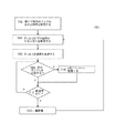
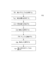
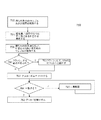
本発明の別の実施形態に従って、自動化臨床分析器で利用するためのオートメーションシステムで利用するための方法は、(少なくとも一つのプロセッサを利用して)双方向トラック上の待ち行列における複数のサンプルに対するサンプル吸引順序を決定することと、順序が乱れた待ち行列における少なくとも一つの第一のサンプルを識別することと、(少なくとも一つの電気信号を介して)第一の格納位置にアクセス可能な双方向トラック上の物理的位置へと双方向トラックに沿って第一のサンプルを動かすことと、を含む。第一のサンプルは、第一の格納位置へと動かされ、複数のサンプル内の間隙が、第一の格納位置にアクセス可能な位置に一致する待ち行列内の第一の予め決められた順序位置に存在するように、複数のサンプルのうちの少なくともサブセットは、少なくとも一つの電気信号を介して動かされる。第一のサンプルは、その後、予め決められた順序位置へと第一の格納位置から動かされる。 In accordance with another embodiment of the present invention, a method for use in an automation system for use in an automated clinical analyzer is for a plurality of samples in a queue on a bi-directional track (using at least one processor). Bi-directionally determining the sample aspiration order, identifying at least one first sample in the out-of-order queue, and accessing the first storage location (via at least one electrical signal) Moving the first sample along the bi-directional track to a physical location on the track. The first sample is moved to a first storage location and a first predetermined sequence position in the queue where the gaps in the plurality of samples coincide with a location accessible to the first storage location. At least a subset of the plurality of samples is moved via at least one electrical signal. The first sample is then moved from the first storage position to a predetermined sequence position.
本発明の一態様に従い、第一のサンプルの体積は、第一の格納位置にある間に、吸引される。本発明の別の態様に従い、第一のサンプルの体積は、双方向トラック上にある間に吸引される。別の態様においては、第一のサンプルを識別するステップは、例えば、挿入ソートアルゴリズムもしくはヒープソートアルゴリズムを実行する少なくとも一つのプロセッサによって実施される。 In accordance with one aspect of the invention, the volume of the first sample is aspirated while in the first storage position. In accordance with another aspect of the invention, the volume of the first sample is aspirated while on the bi-directional track. In another aspect, identifying the first sample is performed by at least one processor executing, for example, an insertion sort algorithm or a heap sort algorithm.
さらに別の態様においては、方法は、順序が乱れた待ち行列内の第二のサンプルを識別することと、少なくとも一つの電気信号を介して、第二の格納位置にアクセス可能な双方向トラック上の物理的位置へと双方向トラックに沿って第二のサンプルを動かすことと、第二のサンプルを第二の格納位置へと動かすことと、を含む。方法は、さらに、複数のサンプル内の間隙が第二の格納位置にアクセス可能な位置と一致する待ち行列内の第二の予め決められた順序位置に存在し、第二の予め決められた順序位置へと第二の格納位置から第二のサンプルを動かすように、複数のサンプルの少なくともサブセットを(少なくとも一つの電気信号を介して)動かす。 In yet another aspect, a method identifies a second sample in an out-of-order queue and on a bi-directional track accessible to a second storage location via at least one electrical signal. Moving the second sample along the bi-directional track to the second physical position and moving the second sample to the second storage position. The method further includes a second predetermined order position in the second predetermined order position in the queue where the gaps in the plurality of samples coincide with a position accessible to the second storage position. At least a subset of the plurality of samples is moved (via at least one electrical signal) to move the second sample from the second storage position to the position.
本発明の一態様に従い、サンプル吸引の順序を決定するステップは、サンプルの複数の優先度を考慮することを含む。本発明の別の態様に従い、順序が乱れた待ち行列内の少なくとも一つの第一のサンプルを識別するステップは、待ち行列の先頭にはないSTATサンプルを識別することを含む。 In accordance with one aspect of the invention, determining the order of sample aspiration includes taking into account a plurality of sample priorities. In accordance with another aspect of the invention, identifying at least one first sample in an out-of-order queue includes identifying a STAT sample that is not at the head of the queue.
本発明のさらなる特徴および利点は、添付の図面を参照して行われる例示的な実施形態の以下の詳細な説明から明らかになるであろう。 Further features and advantages of the present invention will become apparent from the following detailed description of exemplary embodiments, which proceeds with reference to the accompanying drawings.
本発明の前述のおよび他の態様は、添付の図面に関連して読解されるとき、以下の詳細な説明から最良に理解される。本発明を例示する目的のために、現在望ましい実施形態が図面において示されているが、しかしながら、本発明は、開示された特定の手段に限定されることはないことを理解されたい。図面に含まれているのは以下の図である。
[幾つかの実施形態に関連する用語と概念]
分析器:自動臨床分析器(“分析器”)は、臨床化学分析器、自動免疫アッセイ分析器、もしくはその他のタイプのインビトロ診断(IVD)試験分析器を含む。概して、分析器は、複数の患者サンプルに対して自動化された一連のIVD試験を実施する。患者サンプルは、分析器に(手動もしくはオートメーションシステムを介して)装填され、分析器は、その後、各サンプルに対して、免疫アッセイ、化学試験もしくは他の観察可能な試験のうちの一つ以上を実施することができる。分析器という用語は、モジュール分析システムとして構成される分析器のことを称する可能性があるが、それに限定はされない。モジュール分析システムは、オートメーショントラックなどのオートメーション面によって、線形もしくは他の幾何学的形状に相互接続された複数のモジュール(同一タイプのモジュールもしくは異なるタイプのモジュールを含む可能性がある)の任意の組み合わせからなる、一体型の拡張可能システムを含む。幾つかの実施形態においては、オートメーショントラックは、モジュール間で患者サンプルおよび他のタイプの材料を移動させるために独立したキャリアが使用される、一体型輸送システムとして構成されてもよい。概して、モジュール分析システムにおける少なくとも一つのモジュールは、分析器モジュールである。モジュールは、患者サンプルに対して、分析タスクのスループットをより高めるために、特化されるか、冗長化されてもよい。
[Terminology and concepts related to some embodiments]
Analyzer: Automated clinical analyzers (“analyzers”) include clinical chemistry analyzers, automated immunoassay analyzers, or other types of in vitro diagnostic (IVD) test analyzers. In general, the analyzer performs a series of automated IVD tests on multiple patient samples. Patient samples are loaded into the analyzer (manually or via an automation system), and the analyzer then performs one or more of immunoassays, chemical tests, or other observable tests on each sample. Can be implemented. The term analyzer may refer to an analyzer configured as a modular analysis system, but is not limited thereto. A modular analysis system is any combination of multiple modules (which may include the same type of modules or different types of modules) interconnected in a linear or other geometric shape by an automation surface such as an automation track An integrated expandable system comprising: In some embodiments, the automation track may be configured as an integrated transport system where independent carriers are used to move patient samples and other types of material between modules. Generally, at least one module in a module analysis system is an analyzer module. Modules may be specialized or redundant for patient samples to further increase the throughput of analysis tasks.
分析器モジュール:分析器モジュールは、患者サンプルに対して免疫アッセイ、化学試験もしくは他の観察可能な試験などのIVD試験を実施するように構成されたモジュール分析器内のモジュールである。典型的には、分析器モジュールは、サンプル容器から液体サンプルを抽出して、(概して反応器と称される)反応キュベットもしくは反応管内で試薬とサンプルを合わせる。分析器モジュールにおいて可能な試験は、電解質の分画、腎もしくは肝機能、代謝、心臓、ミネラル、血液疾患、薬剤、免疫アッセイ、もしくは他の試験を含むが、そのいずれにも限定はされない。幾つかのシステムにおいては、分析器モジュールは、スループットをより高めるために、特化されてもよいし、または冗長化されてもよい。分析器モジュールの機能は、モジュールアプローチを利用しないスタンドアロン分析器によって実施されてもよい。 Analyzer module: An analyzer module is a module in a module analyzer that is configured to perform IVD tests, such as immunoassays, chemical tests or other observable tests, on patient samples. Typically, the analyzer module extracts a liquid sample from a sample container and combines the reagent and sample in a reaction cuvette or reaction tube (commonly referred to as a reactor). Possible tests in the analyzer module include, but are not limited to, electrolyte fractionation, kidney or liver function, metabolism, heart, minerals, blood disorders, drugs, immunoassays, or other tests. In some systems, the analyzer module may be specialized or redundant to further increase throughput. The functionality of the analyzer module may be performed by a stand-alone analyzer that does not utilize a modular approach.
キャリア:キャリアは、オートメーションシステムにおいてサンプル容器(および、拡大解釈した場合には流体サンプル)もしくは他の物品を移動するために使用することができる輸送ユニットである。幾つかの実施形態においては、キャリアは、従来のオートメーションパック(例えば、チューブもしくは物品をはめ込むためのホルダ、オートメーショントラックにおける外部コンベヤベルトが推進力を与えることを可能にするための摩擦表面、トラックがパックをその宛先へとルーティングすることを可能にするために、パックをオートメーショントラックにおける壁もしくはレールによって誘導することを可能にする複数側面を含む受動デバイス)の様に単純であってもよい。幾つかの実施形態においては、キャリアは、プロセッサ、モーションシステム、誘導システム、センサなどのアクティブコンポーネントを含んでもよい。幾つかの実施形態においては、キャリアは、オートメーションシステムにおける地点間で、キャリアを自己誘導することを可能にする内蔵(onboard)知能を含む可能性がある。他のキャリアでは推進力がトラックなどのオートメーション面によって提供されるのに対して、幾つかの実施形態においては、キャリアが推進力を提供する内蔵コンポーネントを含む可能性がある。幾つかの実施形態においては、キャリアは、決定点間で単一方向(例えば、前後)へと動きを制限するオートメーショントラックに沿って動く。キャリアは、サンプルチューブをはめ込んで運搬するためのチューブホルダを有するなどIVD環境における所定の積載量に特化されてもよいし、または、オートメーションシステム周囲の異なる物品を運搬するのに適した搭載表面を含んでもよい。キャリアは、一つ以上のスロットを含むように構成することができる(例えば、キャリアは、一つもしくは複数のサンプル容器を保持してもよい)。 Carrier: A carrier is a transport unit that can be used to move a sample container (and fluid sample if expanded) or other article in an automation system. In some embodiments, the carrier is a conventional automation pack (e.g., a holder for fitting a tube or article, a friction surface to allow an external conveyor belt in the automation track to provide driving force, a track) It may be as simple as a passive device including multiple sides that allow the pack to be guided by walls or rails in the automation track to allow the pack to be routed to its destination. In some embodiments, the carrier may include active components such as processors, motion systems, guidance systems, sensors, and the like. In some embodiments, the carrier may include onboard intelligence that allows the carrier to self-guide between points in the automation system. In other embodiments, the propulsion is provided by an automation surface such as a truck, whereas in some embodiments, the carrier may include a built-in component that provides the propulsion. In some embodiments, the carrier moves along an automation track that limits movement in a single direction (eg, back and forth) between decision points. The carrier may be specialized for a given load in an IVD environment, such as having a tube holder to fit and transport sample tubes, or a mounting surface suitable for transporting different items around an automation system May be included. The carrier can be configured to include one or more slots (eg, the carrier may hold one or more sample containers).
中央コントローラもしくはプロセッサ:中央コントローラ/プロセッサ(ときには中央スケジューラと称されることがある)は、オートメーションシステムの一部であって、プロセッサ内蔵キャリアのいずれとも別のプロセッサである。中央コントローラは、キャリア用のトラフィック方向、スケジューリングおよびタスク管理を容易にすることができる。幾つかの実施形態においては、中央コントローラは、オートメーションシステムにおけるサブシステムと通信し、キャリアと無線通信をすることができる。これは、キャリアに対して、軌道や操作に関する情報もしくは命令を送信することと、どのキャリアがいつ、どこへ移動するべきかを決定することをも含んでもよい。幾つかの実施形態においては、ローカルプロセッサにトラックの区間上にあるキャリアの局所的な管理を担当させて局所的な待ち行列を管理するなどさせてもよい。これらのローカルプロセッサは、局所的には中央コントローラと同等のものとして機能してもよい。 Central controller or processor: The central controller / processor (sometimes referred to as the central scheduler) is part of the automation system and is a separate processor from any of the processor-incorporated carriers. The central controller can facilitate traffic direction, scheduling and task management for the carrier. In some embodiments, the central controller can communicate with subsystems in the automation system and can communicate wirelessly with the carrier. This may include sending information or instructions regarding the trajectory and operation to the carrier and determining which carrier should move when and where. In some embodiments, a local processor may be responsible for local management of carriers on a track segment, such as managing local queues. These local processors may function locally as being equivalent to the central controller.
決定点(decision point):決定点は、異なるキャリアに対して異なる操作や軌道決定がなされることがある、オートメーショントラックの地点である。よくある例としてトラック内の分岐点(fork)がある。あるキャリアは、方向を変えることなく進むが、別のキャリアは、減速して方向を変える。決定点は、幾つかのキャリアは停止するが他のキャリアは進行することがある、器具における停止点を含んでもよい。幾つかの実施形態においては、方向を変える前の減速領域は決定点としての機能を果たし、方向を変えるキャリアは横力を制限するために減速させ、他のキャリアは、方向を変えない、もしくは当該キャリアのモーションプロファイルが減速することを必要としない場合には進行してもよい。決定点においてなされる決定は、実施形態に応じて、プロセッサ内蔵キャリア、トラック区間を担当するローカルプロセッサ、中央プロセッサもしくはその任意の組み合わせによって行われる可能性がある。 Decision point: A decision point is a point on an automation track where different operations or trajectory decisions may be made for different carriers. A common example is a fork in a track. Some carriers travel without changing direction, while other carriers decelerate and change direction. The decision point may include a stop point in the instrument where some carriers stop but others may progress. In some embodiments, the deceleration region before changing direction serves as a decision point, the changing carrier decelerates to limit lateral force, and the other carriers do not change direction, or If the motion profile of the carrier does not need to slow down, it may proceed. The decision made at the decision point may be made by a carrier with a built-in processor, a local processor responsible for the track section, a central processor, or any combination thereof, depending on the embodiment.
独立キャリア:幾つかの実施形態においては、キャリアは独立して制御されるキャリアとして特徴づけられてもよい。独立して制御されるキャリアは、独立して制御される軌道を有するキャリアである。幾つかの実施形態においては、キャリアが一つもしくはサイズ、重量、フォームファクタおよび/もしくは内容の異なる積載物を複数組み合わせたものを運搬している状況で、独立キャリアは同一トラック上で同時に動作してもよい。各独立して制御されるキャリアの軌道は、オートメーションシステム内で移動中の当該キャリアに対する最大加加速度(maximum jerk)、加速度、方向および/もしくは速度を含むモーションプロファイルによって制限され得る。モーションプロファイルは、各キャリアに対する軌道を独立して制限または規定することができる。幾つかの実施形態においては、モーションプロファイルは、オートメーションシステムの異なる区間(例えば、直線のトラック区間に対し、方向を変える際に付加される横力を生じさせるカーブ付近)、異なるキャリア状態(例えば、空のキャリアはサンプルを輸送するキャリアや試薬もしくは他の品を輸送するキャリアとは異なるモーションプロファイルを有することがある)、および/もしくは異なるキャリアによって異なる可能性がある。幾つかの実施形態においては、キャリアは、モーションプロファイルまたはそれぞれのキャリアに向けた軌道もしくは宛先命令に応じて、個々のキャリアに独立して動作させる内蔵推進コンポーネントを含むことができる。 Independent carrier: In some embodiments, the carrier may be characterized as an independently controlled carrier. An independently controlled carrier is a carrier having an independently controlled trajectory. In some embodiments, independent carriers operate simultaneously on the same track in situations where the carrier is carrying one or a combination of loads of different sizes, weights, form factors and / or contents. May be. The trajectory of each independently controlled carrier may be limited by a motion profile that includes maximum jerk, acceleration, direction and / or velocity for that moving carrier within the automation system. The motion profile can independently limit or define the trajectory for each carrier. In some embodiments, the motion profile is a different section of the automation system (e.g., near a curve that creates a lateral force applied when changing direction for a straight track section), a different carrier state (e.g., An empty carrier may have a different motion profile than a carrier that transports a sample or a carrier that transports reagents or other items), and / or may be different for different carriers. In some embodiments, the carriers can include built-in propulsion components that operate independently on individual carriers in response to motion profiles or trajectories or destination commands directed to each carrier.
知能キャリア/半自律キャリア:幾つかの実施形態においては、キャリアは、知能キャリアとして特徴づけられてもよい。知能キャリアは、動作、ルーティングもしくは軌道決定に寄与する内蔵回路を有するキャリアである。知能キャリアは、オートメーション表面に沿って進行するためのソフトウェア命令をその命令に応じて実行するデジタルプロセッサ、または動作入力に応答する内蔵アナログ回路(例えば、ラインフォロワ回路)を含むことができる。命令は、モーションプロファイル、トラフィック、もしくは軌道ルールを特徴づける命令を含んでもよい。幾つかの知能キャリアは、内蔵プロセッサがキャリアの環境に応じてキャリアをルーティングするか決定を行うことを支援するための内蔵センサも含んでもよい。幾つかの知能キャリアは、内蔵プロセッサの制御に応じてキャリアを動かすことを可能にする、モータもしくは磁石などの内蔵コンポーネントを含んでもよい。 Intelligent carrier / semi-autonomous carrier: In some embodiments, a carrier may be characterized as an intelligent carrier. An intelligent carrier is a carrier with a built-in circuit that contributes to operation, routing or trajectory determination. The intelligent carrier may include a digital processor that executes software instructions to proceed along the automation surface in response to the instructions, or a built-in analog circuit (eg, line follower circuit) that responds to operational inputs. The instructions may include instructions characterizing motion profiles, traffic, or trajectory rules. Some intelligent carriers may also include a built-in sensor to assist the built-in processor in determining whether to route the carrier depending on the carrier environment. Some intelligent carriers may include built-in components such as motors or magnets that allow the carrier to move in response to control of the built-in processor.
インビトロ診断(IVD):インビトロ診断(IVD)は、疾病、状態、感染、代謝マーカを検出でき、体内物質/体液の種々の成分を定量化することができる試験である。これらの試験は、患者の生体外で行われ、研究室、病院、診療所、もしくは他の医療関連施設において実施される。IVD試験は、概して、試験管もしくは他のサンプル容器、より一般的には生体外の制御された環境におけるアッセイからの診断を実施することを意図された医療デバイスを利用する。IVDは、患者の流体サンプルに実施されるアッセイに基づいて、試験および疾病の診断もしくは体内物質/体液の種々の成分を定量化することを含む。IVDは、患者の体液もしくは膿瘍から採取された液体サンプルの分析によって実施できる、患者の診断および治療に関連する種々のタイプの分析試験およびアッセイを含む。これらのアッセイは、典型的には、患者のサンプルを含むチューブもしくはバイアルが装填された分析器で実施される。IVDとは、本明細書に記載のIVDの機能性のいかなる一部をも示し得る。 In Vitro Diagnosis (IVD): In Vitro Diagnosis (IVD) is a test that can detect disease, condition, infection, metabolic markers and quantitate various components of bodily substances / fluids. These tests are performed in vitro by the patient and are performed in a laboratory, hospital, clinic, or other medical facility. IVD testing generally utilizes a medical device intended to perform a diagnosis from a test tube or other sample container, more generally an in vitro controlled environment. IVD involves testing and diagnosing disease or quantifying various components of bodily substances / fluids based on assays performed on patient fluid samples. IVD includes various types of analytical tests and assays related to patient diagnosis and treatment that can be performed by analysis of a fluid sample taken from a patient's bodily fluid or abscess. These assays are typically performed in an analyzer loaded with a tube or vial containing a patient sample. IVD may refer to any part of the functionality of the IVD described herein.
ランドマーク:キャリアが内蔵センサを含む実施形態においては、トラック表面から視認できる/検知できるトラック表面もしくは位置における光学式もしくは他のマークは、ランドマークとして機能する。ランドマークは、現在位置、近づいてくる停止位置、決定点、方向転換、加速/減速点など、キャリアに対する地理的情報を伝送することができる。 Landmark: In embodiments where the carrier includes a built-in sensor, an optical or other mark on the track surface or position visible / detectable from the track surface functions as a landmark. The landmark can transmit geographical information about the carrier such as current position, approaching stop position, decision point, direction change, acceleration / deceleration point.
ラボラトリーオートメーションシステム:研究室オートメーションシステムは、研究室環境内でサンプル容器もしくは他の物品を自動的に(例えば、オペレータもしくはソフトウェアの要求で)動かすことができる任意のシステムを含む。分析器に関連して、オートメーションシステムは、分析器内のステーションへ、ステーションから、ステーション同士で、もしくはステーション間で容器もしくは他の物品を自動的に動かしてもよい。これらのステーションは、モジュール試験ステーション(例えば、あるタイプのアッセイに特化されるか、さもなければ、より大きい分析器へと試験サービスを提供することができるユニット)、サンプル取扱ステーション、保存ステーションもしくは作業セルを含むが、そのいずれにも限定はされない。 Laboratory automation system: A laboratory automation system includes any system that can automatically move sample containers or other items within a laboratory environment (eg, at the request of an operator or software). In connection with the analyzer, the automation system may automatically move containers or other items from station to station, from station to station, or between stations. These stations may be modular test stations (eg, units that are specialized for certain types of assays or otherwise provide test services to larger analyzers), sample handling stations, storage stations or Including, but not limited to, work cells.
モジュール:モジュールは、モジュール分析システム内の特定の(複数の)タスクもしくは(複数の)機能を実施する。モジュールの例には、分析試験用にサンプルを準備する分析前モジュール(例えば、サンプル試験チューブの頭部上のキャップを除去するデキャッパモジュール)、サンプルの一部を抽出して、試験もしくはアッセイを実施する分析器モジュール、分析試験後の保存用にサンプルを準備する分析後モジュール(例えば、サンプル試験チューブを再封(reseal)するリキャッパモジュール)、またはサンプル取扱モジュールを含んでもよい。サンプル取扱モジュールの機能は、在庫管理の目的でサンプルコンテナ/容器を管理すること、分類すること(sorting)、サンプルコンテナ/容器をオートメーショントラック(一体型輸送システムを含んでもよい)内外へ動かすこと、サンプルコンテナ/容器を別のラボラトリーオートメーショントラック内外へ動かすこと、ならびにトレイ、ラック、キャリア、パックおよび/もしくは保存位置内外へサンプルコンテナ/容器を動かすことを含んでもよい。 Module: A module performs a specific task (s) or function (s) within a module analysis system. Examples of modules include a pre-analysis module that prepares a sample for analytical testing (eg, a decapper module that removes the cap on the head of a sample test tube), a portion of the sample that is extracted for testing or assay May include an analyzer module that performs a post-analysis module that prepares a sample for storage after an analytical test (eg, a recapper module that reseals a sample test tube), or a sample handling module. Sample handling module functions include managing sample containers / containers for inventory purposes, sorting, moving sample containers / containers into and out of automation trucks (which may include an integrated transport system), It may include moving the sample container / container into and out of another laboratory automation truck and moving the sample container / container into and out of trays, racks, carriers, packs and / or storage locations.
ペイロード:例示的なキャリアは患者サンプルを運搬することに関連して記述されるが、幾つかの実施形態においては、キャリアは、他の合理的な積載物(payload)をオートメーションシステムにわたって輸送するために利用することができる。これには、流体、流体容器、試薬、廃棄物、使い捨て製品、部品もしくは他の適切な積載物を含んでもよい。 Payload: Although an exemplary carrier is described in connection with carrying a patient sample, in some embodiments, the carrier is for transporting other reasonable payloads across an automation system. Can be used. This may include fluids, fluid containers, reagents, waste, disposable products, parts or other suitable loads.
プロセッサ:プロセッサは、一つ以上のプロセッサおよび/もしくは関連するソフトウェアおよび処理回路のことを称することがある。これは、各実施形態において前述された処理機能を実現するため適切なシングルもしくはマルチコアプロセッサ、単一もしくは複数のプロセッサ、埋め込み型システム、もしくは分散型処理アーキテクチャを含んでもよい。 Processor: A processor may refer to one or more processors and / or associated software and processing circuitry. This may include a single or multi-core processor, single or multiple processors, embedded system, or distributed processing architecture suitable to implement the processing functions described above in each embodiment.
プルアウト、サイドカー、分岐経路:これらの用語は、トラックシステムの主要部分以外のトラック区間のことを称するために使用されてもよい。プルアウトもしくはサイドカーは、弦(chord)、並行トラック、もしくは主要な経路パターンから幾つかのキャリアを分離するための他の適切な手段を含んでもよい。プルアウトもしくはサイドカーは、メインのトラック区間の流れを中断することなく、待ち行列をつくることを物理的に容易にするか、あるキャリアが停止するか減速することを可能にするように構成されてもよい。 Pull-out, sidecar, branch path: These terms may be used to refer to track sections other than the main part of the track system. The pullout or sidecar may include a chord, parallel track, or other suitable means for separating several carriers from the main path pattern. The pull-out or sidecar may be configured to physically facilitate queuing or allow a carrier to stop or slow down without interrupting the main track segment flow. Good.
サンプル:サンプルは、患者(人間もしくは動物)から採取された流体もしくは他のサンプルのことを称し、血液、尿、ヘマトクリット、羊水、またはアッセイもしくは試験を実施するのに適した他の流体を含んでもよい。サンプルは、ときには、校正流体(calibration fluid)もしくは他の患者サンプルを処理するうえで分析器を支援するために使用される他の流体のことを称することがある。 Sample: A sample refers to fluid or other sample taken from a patient (human or animal) and may include blood, urine, hematocrit, amniotic fluid, or other fluid suitable for performing an assay or test. Good. A sample may sometimes refer to a calibration fluid or other fluid used to assist the analyzer in processing other patient samples.
STAT(short turnaround time)サンプル:サンプルは、分析器内の非STATサンプルより先行させるべきサンプルをSTAT優先とするために、研究室情報システム(LIS)もしくはオペレータによって割り当てられた異なる優先度を有してもよい。賢明な方法で利用されると、これによって、あるサンプルの試験過程を他のサンプルよりも迅速に進めることが可能になり、医師もしくは他の医療関係者が試験結果を迅速に受け取ることができる。 STAT (short turnaround time) samples: Samples have different priorities assigned by a laboratory information system (LIS) or operator to prioritize samples that should precede non-STAT samples in the analyzer May be. When used in a sensible manner, this allows the testing process of one sample to proceed more quickly than other samples, and allows physicians or other medical personnel to receive test results quickly.
ステーション:ステーションは、モジュール内で特定のタスクを実施するモジュールの一部を含む。例えば、分析器モジュールと関連付けられたピペッティングステーションは、一体型輸送システムもしくは研究室オートメーションシステム上のキャリアが運搬するサンプルコンテナ/容器からサンプル流体をピペット操作(pipetting)して取り出すために使用される。各モジュールは、モジュールに対して機能性を追加する一つ以上のステーションを含むことができる。 Station: A station includes a portion of a module that performs a specific task within the module. For example, a pipetting station associated with an analyzer module is used to pipette sample fluid from a sample container / container carried by a carrier on an integrated transport system or laboratory automation system. . Each module can include one or more stations that add functionality to the module.
ステーション/モジュール:ステーションは、分析器内の特定のタスクを実施する分析器の一部を含む。例えば、キャッパ/デキャッパステーションは、サンプル容器からキャップを着脱したりする。試験ステーションは、サンプルの一部を抽出して、試験もしくはアッセイを実施することができる。サンプル取扱ステーションは、サンプル容器を管理し、サンプル容器をオートメーショントラック内外へと動かし、保存位置もしくはトレイ内外へとサンプル容器を動かすことができる。ステーションは、モジュールであってもよく、ステーションをより大きい分析器に加えることができる。各モジュールは、分析器に機能性を追加する一つ以上のステーションを含み、分析器は一つ以上のモジュールで構成されてもよい。幾つかの実施形態においては、モジュールは、複数のモジュールおよび/もしくはステーションをリンクしうるオートメーションシステムの一部を含むか、または、オートメーションシステムから分離されてもよい。ステーションは、特定のタスクを実施するための一つ以上の器具を含んでもよい(例えば、ピペットは、免疫アッセイステーションで使用されてオートメーショントラック上のサンプルと接触しうる器具である)。特に指定のない限り、モジュールとステーションの概念は、ほぼ同じ意味で用いられてもよい。 Station / module: A station contains a portion of an analyzer that performs a specific task within the analyzer. For example, a capper / decapper station removes or removes a cap from a sample container. The test station can extract a portion of the sample and perform a test or assay. The sample handling station can manage the sample containers, move the sample containers into and out of the automation track, and move the sample containers into and out of the storage location or tray. The station may be a module and the station can be added to a larger analyzer. Each module may include one or more stations that add functionality to the analyzer, and the analyzer may be composed of one or more modules. In some embodiments, the module may include a portion of an automation system that may link multiple modules and / or stations, or may be separate from the automation system. A station may include one or more instruments for performing a particular task (eg, a pipette is an instrument that can be used in an immunoassay station to contact a sample on an automation track). Unless otherwise specified, the concepts of module and station may be used interchangeably.
チューブ/サンプル容器/流体容器:キャリア表面を汚染することなくキャリアがサンプルを輸送できるように、サンプルは、試験管もしくは他の適切な容器などの容器で運搬されてもよい。 Tube / sample container / fluid container: The sample may be transported in a container such as a test tube or other suitable container so that the carrier can transport the sample without contaminating the carrier surface.
[例示的実施形態]
本明細書で開示される自動臨床化学分析器(分析器)内の待ち行列を処理するための改良された例示的装置および方法のうちのいくつかを利用することにより、従来技術における幾つかの問題点の解決または解消が可能になる。つまり、サンプルキャリアを含むトラックに隣接する格納位置を提供すれば、FIFO方式の待ち行列を使用してもサンプルにランダムアクセスすることが可能となる。サンプルの移動に使用されるトラックは待ち行列内に含まれるサンプルを保持していることにもなるため、サンプルを処理するために必要とされる空間を特定の従来技術の機構よりも減らすことが可能となる。つまり、待ち行列用に必要とされるトラック空間の大きさは、待ち行列内のサンプル数に対して正比例する。カルーセルタイプの装置を用いたランダムアクセス待ち行列を実装する従来技術の機構は、より大きな空間を必要とする。なぜなら、必要とされる空間の大きさは待ち行列に含まれるサンプル数の二乗に比例して増加するからである。さらには、トラックは、サンプルを輸送するために既に使用されているため、待ち行列を処理するために必要となり追加される空間は僅かですむ。待ち行列を保持するトラックは、メイントラックもしくはサイドカー/プルアウトなどのサイドトラックとして機能するトラック区間を含む任意の適切なトラック区間である可能性がある。
Exemplary Embodiment
By utilizing some of the improved exemplary apparatus and methods for processing queues in automated clinical chemistry analyzers (analyzers) disclosed herein, several in the prior art The problem can be solved or solved. That is, if a storage position adjacent to a track including a sample carrier is provided, it is possible to randomly access a sample even using a FIFO queue. The track used to move the sample will also hold the samples contained in the queue, thus reducing the space required to process the sample over certain prior art mechanisms. It becomes possible. That is, the amount of track space required for the queue is directly proportional to the number of samples in the queue. Prior art mechanisms that implement random access queues using carousel type devices require more space. This is because the required space size increases in proportion to the square of the number of samples included in the queue. In addition, since the truck is already used to transport samples, it requires little additional space to process the queue. The track holding the queue may be any suitable track segment including a track segment that functions as a main track or a side track such as a sidecar / pullout.
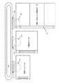
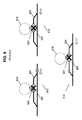
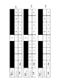
分析器内でサンプルの輸送に使用されるトラック構造の従来技術の構成において典型的な例を図1に示す。このトラックには、トラックシステムを設計するうえでの問題を起こしうる、従来技術の摩擦トラックが含まれる可能性がある。本発明のある実施形態に同様の構造を利用することもできるが、動作用に摩擦トラックを必ずしも使用することはない。トラック100は、ほぼ楕円形状のトラックであり、サンプル準備ステーションや分析/試験ステーション110、120および130などの種々のステーション間をパックもしくはトレイでサンプルを運ぶことができる。トラック100は、単一方向のトラックであるか、幾つかの例においては、線形の双方向トラックである。この例示的構成においては、各分析器110、120、130には、其々サイドカー112、122、132が使用される。トラック100と各サイドカーの分岐合流点には、サンプルをトラック100からサイドカーへと向かわせるゲートもしくはスイッチが配置される。トラック100の楕円の特性は、各分析器に対するアクセスを待つ間、サンプルを循環させるために用いることができる。例えば、分析器110においてサイドカー112が待ち行列で一杯になってしまい、分析器110がサイドカー112上で保留になっているサンプルを処理し終えてトラック100上の本流(main traffic flow)に戻すまでプルアウト112へ新たにサンプルを引き入れられないという場合がある。
A typical example of a prior art configuration of a track structure used for sample transport within an analyzer is shown in FIG. This track can include prior art friction tracks that can cause problems in designing the track system. A similar structure may be utilized for certain embodiments of the present invention, but a friction track is not necessarily used for operation. The
従来技術のシステムにおいては、各サイドカーに、サンプルプローブアーム114、124および134などの取り扱い機構が使用されることがある。これらのロボット的取扱アームは、プローブ針を介してサイドカー内のサンプルからサンプル物質を吸引したり、サイドカーからサンプルチューブを取り出して対応する試験ステーションへと輸送したりすることができる。この例示的システムにおいて、利用可能な試験ステーションには、免疫アッセイステーション110、小規模化学ステーション120および拡張可能な希釈/ISE電解質および大規模化学ステーション(もしくは複数のステーション)130がある。この方法の利点として、トラック100は自己完結型ステーションに加えられるような分離したラボラトリーオートメーションシステムの一部であって、トラック100およびステーション110、120、および130を単独でアップグレード、購入もしくは使用することができるという点などがある。大規模化学ステーション130などのステーションには、トラック100と独立して動作する専用の摩擦トラック136を含むものもある。摩擦トラック136は、大規模化学ステーション130のサブモジュール間でサンプルを移動させる双方向摩擦トラックを含み得る。このタイプのシステムの欠点は、別々の摩擦トラックは独立して動作し、オートメーション全体の制御がより複雑になる点である。さらには、摩擦トラック136と100の間の移行には、特に二つの摩擦トラック間を直結するルートが存在しない場合、時間がかかりかつ面倒になる可能性がある。幾つかのシステムにおいては、トラック間での移動に、ロボットアームを介してサンプルを持ち上げたり設置したりすることが必要となることがある。
In prior art systems, a handling mechanism such as
従来技術の分析器用研究室オートメーションシステムは、概して個々の分析器試験ステーションをトラック上のサンプル用の汎用の宛先として扱う。本発明の幾つかの実施形態においては、研究室オートメーションシステムは、個々の試験ステーション内に統合することができ、個々の試験ステーションの複雑性を実質的に軽減するか排除し、各ステーション内でサンプル取扱システムを分離する必要性を減少させる。幾つかの実施形態においては、研究室オートメーションシステムをステーションへと統合することによって、システムは、汎用宛先としてよりは、サンプルが移動することができるマルチルートトラックの一部として、個々のステーションの扱いを開始することができる。 Prior art analyzer laboratory automation systems generally treat individual analyzer test stations as general destinations for samples on the track. In some embodiments of the present invention, laboratory automation systems can be integrated into individual test stations, substantially reducing or eliminating the complexity of individual test stations, and within each station. Reduce the need to separate sample handling systems. In some embodiments, by integrating a laboratory automation system into a station, the system treats individual stations as part of a multi-root track through which samples can travel rather than as a universal destination. Can start.
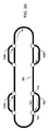
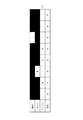
図2Aは、本発明での使用のために適応することができるトラックシステムの一実施形態を示す。トラック150は、時計回り(もしくは反時計回り)方向にサンプルキャリアが移動する長方形/楕円/円形トラックである。トラック150は、一方向であってもよいし、双方向であってもよい。キャリアは、流体サンプル、試薬もしくは廃棄物など、あらゆる適切なペイロードをIVD環境内で輸送することができる。患者サンプルなどの流体は、試験管、バイアル、キュベットなど、キャリアによって輸送できる容器もしくは器に配置することができる。キャリア(拡大解釈すると、サンプルなどのペイロード)は、メイントラック150上を移動することができるか、164もしくは166などの決定点を経て方向転換することができる。これらの決定点は、(従来技術と同様に)機械的ゲートであるか、メイントラック150から本明細書に記載されるような160、160A、160B、160Cなどのサイドカーへとサンプルを方向転換させるのに適切な他の機構とすることができる。例として、あるサンプルキャリアがメイン経路150を移動して、決定点166に到達する場合、サンプルキャリアは、セグメント162へとメイントラック上にあり続けてもよいし、またはサイドカー160へと方向転換させてもよい。決定点166においてサンプルキャリアを方向転換するための決定がなされるシステムおよび方法を記載する。
FIG. 2A illustrates one embodiment of a track system that can be adapted for use with the present invention. The
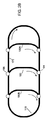
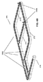
図2Bは、本発明のある実施形態用に適した別のトラックレイアウトを示す。トラック170もほぼ円形のトラックであり、サンプルキャリアは、時計周り(もしくは反時計回り)に移動する。本実施例においては、トラック外にサイドカーを有するのではなく、トラック内の弦となるプルアウト180、180Aおよび180Bがある。同様に、サンプルキャリアが決定点に到達すると、メイン経路から経路180などのサイド経路へと方向転換してもよい。決定点186において、メイントラック170上のサンプルは、メイントラック上にあり続けてもよいし、経路180へと方向転換されてもよい。いったん取扱経路180に沿った分析器ステーションがサンプルの処理を終えると、サンプルは、決定点184へと進み、メイン経路170へと戻される。
FIG. 2B shows another track layout suitable for an embodiment of the present invention. The
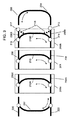
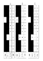
図3は、本発明のある実施形態で利用することができるオートメーションシステムトラックに対するモジュールアプローチを示す。本実施例においては、トラックを個々の分析器ステーションへ統合し、トラックが個々の研究室ステーションの内部作動もしくはサンプル取扱システムの一部として使用されるようにしてもよい。従来技術においては、異なる分析器/試験ステーション内に複数の異なるタイプの作動システムを有することがよくある。例えば、幾つかのステーションは、サンプルチューブのパックもしくはトレイを往復させるための摩擦トラックを含み、サンプルの一部を吸引して分注できるキュベットおよび反応容器などのより小さい器を含むカルーセルを含んでもよい。幾つかの実施形態においては、トラックシステムの一部を分析ステーション自体へと統合することによって、各ステーションが、独自の待ち行列論理を含み、不必要な内部作動システムを排除するために簡略化されてもよい。 FIG. 3 illustrates a modular approach to an automation system track that can be utilized with an embodiment of the present invention. In this embodiment, the trucks may be integrated into individual analyzer stations so that the trucks are used as part of the internal operation or sample handling system of individual laboratory stations. The prior art often has multiple different types of actuation systems in different analyzers / test stations. For example, some stations may include a friction track for reciprocating a pack or tray of sample tubes and a carousel containing smaller vessels such as cuvettes and reaction vessels that can aspirate and dispense a portion of the sample. Good. In some embodiments, by integrating a portion of the track system into the analysis station itself, each station includes its own queuing logic and is simplified to eliminate unnecessary internal operating systems. May be.
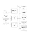
図3を参照すると、トラック200は、分析器モジュールに統合されるモジュールコンポーネントへと分解できる。本例示的トラックにおいては、モジュール205、205Aおよび205Bを互いに組み合わせ、任意で、他のモジュールトラックコンポーネント202および204とも組み合わせて図2Bに示されたトラックと類似のトラックを形成することができる。例えば、205Aは、免疫アッセイ110(図1)と同一の機能を果たすモジュールであって、205は、小型化学モジュール120(図1)と同一の機能を果たすモジュールであって、205Bは、モジュール130(図1)のようにISE電解質試験を実施するモジュールとすることができる。この例では、トラックセグメント202、204、206、206A、206B、208、208Aおよび208Bによって外部メイントラックを形成することができる。分析器モジュール205、205Aおよび205B内で、内部経路210、210Aおよび210Bは、メイントラックからのプルアウトを形成する。内部経路は、内部待ち行列用に用いられ、各モジュールが処理されるサンプルをよりうまく制御できるように、各分析器モジュール内で別々に管理され得る。
Referring to FIG. 3, the
トラック200ならびにサブ経路210、210Aおよび210Bを其々分析器モジュール205、205Aおよび205Bへと統合する利点の一つは、各分析器モジュール内の内部取り扱い機構をトラックサブ経路とより良好に連携するように特別に適応させることができることである。幾つかの実施形態においては、モジュール205、205Aおよび205Bは、分析器全体の動作サイクルよりも短い期間内に各サンプルを処理するように適応することができるため、サンプルを処理後にトラックシステムに沿って別のモジュールへとルーティングするのに十分な時間が残り、他のモジュールは次の動作サイクルでそのサンプルを即座に処理することができる。本明細書で用いられるように、動作サイクルは、サンプルアッセイ用にモジュールに処理時間を割り当てるスケジューリングアルゴリズムで用いられる単位時間である。これらは動的であってもよいし、固定されてもよく、分析器内のモジュールに同期動作をさせ、分析器内の複数モジュール間でサンプルをスケジューリングするための信頼できるタイミングモデルを提供することができる。動作サイクル時間は、最初のサンプルの処理開始時刻から想定内の定常状態条件下で別のサンプルを処理する準備ができた時刻までに、任意のモジュールが必要とする時間として選択してもよい。例えば、分析器が3秒毎に1試験を処理でき、サンプルあたりの予測される平均試験は7回である場合、動作サイクル時間は21秒とすることができる。サンプルあたりの試験回数が予測される回数から変化するとしても、個々のモジュールは、スループットを最大化するために、並列処理もしくは1サイクル内で複数のサンプルを処理するなどの効率化技術を実施することができることを理解されたい。さらには、幾つかの実施形態においては、個々のモジュールは異なる動作サイクル時間を有し、これらのモジュール同士は実質的に非同期的に動作することができることを理解されたい。サイクル時間や要求がモジュール間で異なる場合、仮想待ち行列もしくはバッファを、サンプルスケジューリングの管理を支援するために使用することができる。
One advantage of integrating the
安定したタイムフレーム、およそ1動作サイクル以下、で分析器内のモジュール間の通過を可能にすることで、従来技術のトラックシステムで不可能だった多くの性能的な優位性を達成することができる。あるサンプルが分析器の単一サイクル内に分析器モジュールによって確実に処理されて次の分析器モジュールへと輸送することが可能な場合、待ち行列ができた際の流れの処理は、より単純になり、スループットはより安定し、かつレイテンシーは制御されて減少する可能性がある。本質的に、当該分析器においては、サンプルはトラックシステムによって確実に処理され、1つのサンプルも無為にトラックシステム上で待ち行列で待機していないように一律に処理することができる。さらには、任意の分析器モジュール内の待ち行列など、システム内の待ち行列は、システム内のモジュールの数によって制限されて確実に短縮され得る。 By allowing passage between modules in the analyzer in a stable time frame, approximately 1 operating cycle or less, many performance advantages not possible with prior art truck systems can be achieved. . If a sample is reliably processed by the analyzer module within a single cycle of the analyzer and can be transported to the next analyzer module, the processing of the flow when queued is simpler The throughput is more stable and the latency can be controlled and reduced. In essence, in the analyzer, samples are reliably processed by the track system, and a single sample can be processed uniformly so that it is not inadvertently waiting in a queue on the track system. Furthermore, queues in the system, such as queues in any analyzer module, can be reliably shortened by being limited by the number of modules in the system.
本発明の幾つかの実施形態においては、トラックシステムの確実かつ迅速な特性は、待ち行列が物理的ではなく仮想的であることを可能とする。仮想待ち行列は、物理的制限によってではなく、ソフトウェアで扱うことができる。従来、待ち行列は物理的であった。最も単純な物理待ち行列は、サンプル処理動作のある部分における事実上の交通渋滞である。ボトルネックによってファストインファストアウト(FIFO)待ち行列が生成され、そこでサンプルキャリアを一列にして事実上停止させて、準備が整い次第分析器もしくは決定点が待ち行列内の次のサンプルを要求できるようにバッファを提供する。ほとんどの従来技術の研究室オートメーショントラックは、付属モジュール(分析器もしくは前/後分析デバイス)による処理待ちのサンプルをバッファするために、FIFO方式の処理待ち行列を保持する。モジュールもしくはオペレータの要求によって需要が急増したとしても、これらのバッファによってトラックは一定の速度でサンプルチューブを処理することが可能となる。例えば、現在のサンプルの処理中にキュベットを準備したり試薬を吸引したりする等、後のサンプルの前処理タスクを個々のモジュールに実施させることにより、FIFO待ち行列は、個々のモジュールのスループットを実質的に増加させることもできる。FIFO待ち行列によって確実に予測可能となることによって、幾つかの処理タスクを並列化することが可能となるが、リソースを最適化するために、サンプルに対する試験を再順序付けすることによって、モジュールが場当たり的なスケジューリングを用いることを防止でき、スループットを増加させることができる。例えば、ほとんどの免疫アッセイ分析器の内部リソース競合は非常に複雑であるため、分析器は、最大効率を達成するために、複数のサンプルから試験をインターリーブする必要がある。FIFO待ち行列によってこれらの分析器のスループットは20%程度減少する可能性がある。FIFO待ち行列の別の問題点として、優先度を有するサンプル(例えば、STATサンプル)を処理する能力がないことがある。STATサンプルを即座に処理する必要がある場合、FIFO待ち行列全体がフラッシュされメイントラック上へ戻されなければならず、トラック上の他のサンプル全てを遅延させ、元のモジュールにその待ち行列をゆっくりと再構築させることとなる。 In some embodiments of the invention, the reliable and rapid nature of the truck system allows the queue to be virtual rather than physical. Virtual queues can be handled by software, not by physical limitations. Traditionally, queues were physical. The simplest physical queue is a virtual traffic jam in some part of the sample processing operation. The bottleneck creates a fast-in-fast-out (FIFO) queue where the sample carriers are effectively queued so that the analyzer or decision point can request the next sample in the queue when ready. Provide a buffer for. Most prior art laboratory automation trucks maintain a FIFO-style processing queue to buffer samples awaiting processing by an attached module (analyzer or pre / post analysis device). These buffers allow the truck to process the sample tube at a constant rate, even if demand increases rapidly due to module or operator demand. By allowing individual modules to perform subsequent sample pre-processing tasks, such as preparing cuvettes and aspirating reagents during the processing of the current sample, the FIFO queue can increase the throughput of individual modules. It can also be increased substantially. Certainly predictable by the FIFO queue allows several processing tasks to be parallelized, but by optimizing the resources, reordering the tests on the samples Can be prevented and throughput can be increased. For example, the internal resource competition of most immunoassay analyzers is so complex that the analyzer needs to interleave the test from multiple samples in order to achieve maximum efficiency. FIFO queuing can reduce the throughput of these analyzers by as much as 20%. Another problem with the FIFO queue is that it does not have the ability to process samples with priority (eg, STAT samples). If a STAT sample needs to be processed immediately, the entire FIFO queue must be flushed and moved back onto the main track, delaying all other samples on the track, and slowing down the queue to the original module Will be rebuilt.
もう一つのタイプの待ち行列は、ランダムアクセス(RA)待ち行列である。カルーセルは、分析器モジュールにある物理的ランダムアクセス(RA)待ち行列の一例である。サンプルを一部ずつカルーセルリング内の一つ以上の容器内に分けることによって、分析器モジュールは、分析器内で処理する複数のサンプルのうちいずれかをいつでも選択することができる。しかしながら、カルーセルは、複雑性、サイズおよびコストを増大させるなどの多くの欠点を有する。カルーセルは、定常状態処理時間も増加させる。なぜなら、サンプルをランダムアクセス待ち行列の内外へと移動させなければならないからである。処理遅延は、カルーセル内の配置数などの実装に依存する。一方で、サンプルに対してランダムアクセスを有することによって、モジュール内のローカルスケジューリング機構は、所望の任意の順序でサブステップを実施してサンプルを並行処理することができる。 Another type of queue is a random access (RA) queue. A carousel is an example of a physical random access (RA) queue in the analyzer module. By dividing the sample partly into one or more containers in the carousel ring, the analyzer module can select any of the multiple samples to be processed in the analyzer at any time. However, carousels have many disadvantages such as increased complexity, size and cost. The carousel also increases steady state processing time. This is because samples must be moved in and out of the random access queue. The processing delay depends on the implementation such as the number of arrangements in the carousel. On the other hand, by having random access to the samples, the local scheduling mechanism within the module can perform the sub-steps in any desired order to process the samples in parallel.
幾つかの実施形態においては、モジュールからカルーセルもしくは他のRA待ち行列を除いて、オートメーションシステムのサブ経路(例えば210)をRAもしくはFIFO待ち行列の一部として使用することができる。即ち、任意の二点間のサンプルの移動時間がカルーセルの移動時間に類似する(動作サイクルの一部よりも短いと予想される)既知の時間に限定することができる場合、トラック200を、任意のモジュールにおいて待ち行列の一部とすることができる。例えば、カルーセルを利用するのではなく、モジュール205は、サブ経路210上のキャリアのサンプルを利用することができる。試薬準備などの前処理ステップは、試験対象サンプルの到着前に実施できる。いったん試験対象サンプルが到着すると、サンプルの一以上の部分は吸引され、アッセイ用にキュベットもしくは他の反応容器内に入れられる。幾つかの実施形態においては、これらの反応容器は、モジュール205内でトラックの外に格納され、他の実施形態においては、これらの反応容器は、動作を容易にするために、サブ経路210上のキャリア内に配置することができる。試験対象サンプルが、動作サイクルよりも長い間モジュールに留まる必要がある場合、もしくは1動作サイクル中に複数サンプルがモジュールによって処理される場合、サブ経路210は、そのモジュールの待ち行列として機能することができる。
In some embodiments, excluding a carousel or other RA queue from the module, the automation system sub-path (eg, 210) can be used as part of an RA or FIFO queue. That is, if the sample travel time between any two points can be limited to a known time that is similar to the carousel travel time (expected to be shorter than part of the operating cycle), the
さらには、他のモジュールにありまだ試験対象となっていないサンプルを、次の動作サイクルのスケジュールに入れることができる。これらの次のサイクルのサンプルは、モジュール205用の仮想待ち行列内に存在するものとして考えることができる。モジュールは、トラック200上の任意のサンプルについて、ある動作サイクル中にサンプルが到着するようにスケジュールを組むことができる。中央コントローラもしくはモジュール自身に関連付けられた複数のコントローラは、あるサイクル中に、1つのサンプルに対して任意の競合が起こることを解決することができる。サンプルの到着時間の情報を予めモジュールに与えることによって、各モジュールはリソースを準備して、内部リソースをより効率的に割り当てるために試験もしくは試験の一部をインターリーブすることができる。この方法においては、モジュールは、大きな物理的バッファを利用することによってではなく、ジャストインタイム方式でサンプルに対して動作することができる。効果として、所定のモジュールに対する仮想待ち行列は、当該モジュール用のサブ経路の物理容量よりも非常に大きくなる可能性があり、既存のスケジューリングアルゴリズムを使用できることがある。事実上、各モジュールは、従来技術のモジュールにおいてサンプルカルーセルを扱うようにトラック200を扱うことができる。
In addition, samples in other modules that have not yet been tested can be scheduled for the next operating cycle. These next cycle samples can be considered as being in the virtual queue for
仮想待ち行列を使用することによって、幾つかの実施形態においては、複数モジュールは複数の待ち行列を有することもできるし、一つの待ち行列を共有したり、一つの待ち行列内のサンプルを共有したりすることができることを理解されたい。例えば、二つのモジュールがある一つのアッセイを実施するようになっている場合、アッセイを必要とするサンプルは、当該アッセイの仮想待ち行列に割り当てられ、アッセイを処理可能な二つのモジュール間で共有される。これによって、モジュール間の負荷のバランスがとれ、並列処理を容易にすることができる。反応容器がトラック200上のキャリア内に配置される実施形態においては、アッセイは、あるモジュール(例えば、試薬が準備されたおよび/もしくはサンプルが混ぜられた)で開始され、当該アッセイは別のモジュールで完了することができる(例えば、反応が別のモジュールで観察される)。幾つかの実施形態においては、複数のモジュールは、事実上、サンプルを扱うためのマルチコアプロセッサとして考えることができる。これらの実施形態において、複数のモジュール用のスケジューリングアルゴリズムは、ある動作サイクル中にサンプルが競合することを回避するように調整されるべきである。
By using virtual queues, in some embodiments, multiple modules can have multiple queues, share a single queue, or share samples in a single queue. Please understand that you can. For example, if two modules are to perform an assay, the samples that require the assay are assigned to the assay's virtual queue and are shared between the two modules capable of processing the assay. The As a result, the load between the modules can be balanced and parallel processing can be facilitated. In embodiments in which the reaction vessel is placed in a carrier on the
仮想待ち行列を使用することによって、サンプルが他のモジュールの仮想待ち行列内にある間に、モジュールはそのサンプルに対して動作できる。これによって、サンプルのレイテンシーを低くおさえられる。なぜなら、トラック200上に配置される各サンプルを、物理待ち行列で待機させることなく、モジュールが試験を完了するのと同じくらい迅速に処理できるからである。これによって、任意の時間におけるトラック200上でサンプルキャリアの数を大きく減少させ、安定したスループットを可能とする。待ち行列もしくはサンプルをモジュール間で共有させることによって、負荷バランスを用いて、システムのスループットを最大化することもできる。
By using a virtual queue, a module can operate on a sample while the sample is in another module's virtual queue. This keeps the sample latency low. This is because each sample placed on the
仮想待ち行列を利用する別の利点は、STATサンプルに対して動的な優先度の割り当てが可能になることである。例えば、大部分が静的な物理待ち行列の先頭へと、STATサンプルを飛び越えるために物理的バイパスを使用しなければならないのではなく、STATサンプルは、ソフトウェア内の次の動作サイクルの待ち行列の先頭に移動させることができる。例えば、次の動作サイクル中にトラック200によって3つのサンプルがアッセイ用に送達されることをモジュールが予測している場合、そのモジュールへとサンプルを割り当てる担当のスケジューラは、一つ以上のサンプルとSTATサンプルを単に置きかえればよく、次の動作サイクル中に処理するためのSTATサンプルをトラック200に送達させることができる。
Another advantage of using a virtual queue is that it enables dynamic priority assignment for STAT samples. For example, rather than having to use physical bypass to jump over STAT samples to the top of a mostly static physical queue, STAT samples are queued for the next operating cycle in software. It can be moved to the top. For example, if a module predicts that three samples will be delivered for assay by
幾つかの実施形態では仮想待ち行列が使用できるが、幾つかの実施形態においては、分析器の少なくとも一部に対して物理待ち行列を用いる。例えば、分析器用のピペットを提供するサブ経路は、サンプルがピペットとの接触を待つため当該サブ経路上に物理待ち行列ができることがある。この待ち行列の管理には、仮想化することが含まれ、物理バッファとしてサブ経路のトラックを利用することも含まれ得る。この物理バッファは、本明細書で説明されたように、FIFO待ち行列を含み得るし、待ち行列を保持するトラックにアクセス可能な格納位置を利用することによって、ランダムアクセス方式で動作することもできる。この待ち行列の仮想化は、モジュール間のサンプルの相互関係を管理するために役立たせることができる。しかしながら、分析器内のサンプルの物理的管理を可能とするために、特定のトラック区間上では物理バッファを使用することも可能である。物理待ち行列としてトラック区間を利用することによって、これらの物理待ち行列は、サンプルの保存空間を追加する必要なくより大きい仮想待ち行列の一部として管理することができる。物理待ち行列を利用することによって、トラックは、サンプル用の輸送機構として機能することができるとともに、ピペットでサンプルが吸引されないときには、サンプルの物理的な保存場所としても機能することができる。 In some embodiments, a virtual queue can be used, but in some embodiments, a physical queue is used for at least a portion of the analyzer. For example, a sub-path that provides a pipette for an analyzer may have a physical queue on the sub-path for the sample to wait for contact with the pipette. This queue management includes virtualization, and may also include using sub-path tracks as physical buffers. This physical buffer can include a FIFO queue, as described herein, or can operate in a random access manner by utilizing a storage location accessible to the track holding the queue. . This queue virtualization can help to manage the interrelationship of samples between modules. However, it is also possible to use physical buffers on specific track sections in order to allow physical management of the samples in the analyzer. By utilizing track segments as physical queues, these physical queues can be managed as part of a larger virtual queue without the need to add sample storage space. By utilizing a physical queue, the truck can serve as a transport mechanism for the sample and can also serve as a physical storage location for the sample when the sample is not aspirated with a pipette.
214および216などの決定点を能率化して各決定点において待ち行列を不要とできる場合、物理待ち行列はサブ経路210、210Aおよび210B内にのみ形成され得る。上述されたように、これらは、RA待ち行列もしくはFIFO待ち行列として扱われる。STATサンプルがトラック200上に置かれた場合、このSTATサンプルは即座に処理できるため、サブ経路210、210Aおよび210B内のRA待ち行列は、フラッシュされる必要がない。FIFO待ち行列はいずれも個々にフラッシュされることとなる。例えば、STATサンプルが区間222においてトラック200上に置かれる場合、サンプルは、外側トラックおよび決定点216を介して、該当する分析器205Bへとルーティングされることとなる。経路210Bにおける待ち行列で待機している他のサンプル(および、拡大解釈すると、それらのサンプルを輸送するサンプルキャリア)がある場合、STATサンプルを優先させるために、待ち行列内のサンプルのみ、フラッシュする必要がある。外側トラック200が動作サイクル以下の時間で周回すると仮定される場合、210Bにおける待ち行列からフラッシュされたサンプルはいずれも、トラック周囲を単に循環してすぐに経路210Bにおける待ち行列へと戻りSTATサンプルのすぐ後ろに置かれることとなり、STATサンプルが原因で発生するダウンタイムをなくすことができる。
Physical queues can only be formed in
進入経路220および222は、トラック200にサンプルを投入するために使用することができる。例えば、通常の優先度を有するサンプルは、入力220においてトラック200上に置かれ、STAT優先度を有するサンプルは、入力222においておくことができる。これらの投入物は、完了するとサンプルの産出物として使用されるか、または、使用したサンプルの排出経路として(図示されていない)他のポートを使用することができる。入力220は、トラック200に対するアクセスを求める入力サンプルのFIFO待ち行列の役割を果たす入力バッファとして実現することができる。サンプルが入力220の待ち行列の先頭に到達すると、(キャリア内に配置されるか、またはキャリアが入力220内に配置されたときそのキャリア内に配置されることによって)サンプルをトラックへ移動させることができる。STATサンプルは、入力222に配置された直後にトラック200に進入でき、トラック200が混雑している場合には、STATサンプルは、次の利用可能で空いている動作サイクルでトラックに進入することができる。幾つかの実施形態は、1動作サイクル中のトラック上のキャリア数を監視して、総数を管理可能な量に制限し、残りは投入待ち行列に残しておく。投入時にサンプルを制限することによって、トラック200の混雑をなくし、常に可能な限り最も効率的な方法で動作することが可能となる。これらの実施形態においては、あるサンプルが二つのモジュール間を通過する時間は、限られた値(例えば、動作サイクルの幾らかの部分よりも短い)となり、たスケジューリングが簡略化される。
The
幾つかの実施形態においては、トラックシステム200は、双方向であるように設計することができる。これは、サンプルキャリアが外側経路および/もしくはいずれのサブ経路をどちらの方向にも移動することができることを意味する。幾つかの実施形態においては、さらなる決定点215および217を介してアクセスされる211Bなどのさらなるサブ経路によって、双方向アクセスの提供を支援することができる。双方向経路は、固有の利点を有し得る。例えば、通常の優先度のサンプルが常に同一方向に処理される場合、STATサンプルは、サブ経路に沿って反対方向に処理することができる。これは、STATサンプルが実質的にサブ経路の出口に進入し、待ち行列をフラッシュする必要なく即座に待ち行列の先頭に置かれることを意味する。例えば、STATサンプルがセグメント204においてトラック200上に置かれる場合、決定点214を介して経路210Bに進入し、どの待ち行列の先頭にも即座に置かれるように経路210Bへと進むことができる。一方、これらの例の全てにおいて、待ち行列は通常サブ経路にあると限定されると仮定されるため、他のモジュールにおいては、STATサンプルがそれらのモジュールに対して即座にアクセスする必要がなければ、待ち行列をフラッシュする必要がない。その後のサイクルでSTATサンプルを処理する必要があるモジュールがさらにあれば、その時点でそれらのモジュールの待ち行列をフラッシュしてもよく、各分析器モジュールの動作を中断させることなく、STATサンプルへジャストインタイム方式のアクセスをする。
In some embodiments, the
モジュール設計には、他にも特定の利点がある。分析器モジュール内のオートメーションシステムがモジュールに含まれるトラックシステムを利用するように適応される場合、通常のトラックを利用する新規の特徴を加えることができる。例えば、モジュールは、サンプル用に指定されるアッセイを実施するために必要な試薬全てを含むそのモジュール専用の内部試薬カルーセルを用いてもよい。分析器モジュール内にストックされた試薬が少なくなってきたとき、幾つかの実施形態においては、オペレータがトラック200上のキャリアに追加の試薬を装填するだけで、試薬を補充することができる。トラック200上の試薬が該当するモジュールに到達すると、モジュールは、トラックから試薬を取り出して、モジュールの試薬貯蔵場所に試薬を置くアームもしくはフィーダシステムなどの機械システムを利用することができる。
There are other specific advantages to modular design. If the automation system in the analyzer module is adapted to utilize the track system included in the module, new features that utilize regular tracks can be added. For example, a module may use an internal reagent carousel dedicated to that module that contains all the reagents necessary to perform the assay specified for the sample. When less reagent is stocked in the analyzer module, in some embodiments, the operator can replenish the reagent by simply loading the carrier on the
幾つかの実施形態においては、図3および図2Aおよび図2Bに示された個々のトラック部分は、互いに独立して動作することができるか、または、受動的となり得る。独立したキャリア移動は、サンプルキャリアを移動させるために摩擦トラック全体が移動しなければならないような非局在化コンベヤベルトなどの摩擦ベースのトラックシステムに勝る利点を提供する。これは、当該トラック上の他のサンプルも同一速度で移動しなければならないことを意味する。これはまた、特定の区間が異なる速度で動作する場合、サンプルを運搬する受動的キャリア間で衝突が起こる可能性があることも意味する。 In some embodiments, the individual track portions shown in FIGS. 3 and 2A and 2B can operate independently of each other or can be passive. Independent carrier movement provides an advantage over friction-based track systems such as delocalized conveyor belts where the entire friction track must be moved to move the sample carrier. This means that other samples on the track must also move at the same speed. This also means that collisions can occur between passive carriers carrying samples if certain sections operate at different speeds.
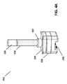
図4Aは、本発明で利用するための例示的なキャリア250を示す。キャリア250は、異なる実施形態においては、異なるペイロードを保持することができる。あるペイロードは、血液もしくは尿などの流体サンプル256を含むサンプルチューブ255とすることができる。他のペイロードには、チューブのラック、試薬カートリッジもしくは他の適切なカートリッジを含んでもよい。サンプルキャリア250は、本明細書で記述された内部電子コンポーネントを収容できるメイン筐体ボディ260を含む。メイン筐体260は、ペイロードを収受できるブラケット262を支持する。幾つかの実施形態においては、これは、サンプルチューブなどの流体容器255を収受し、かつ、それを摩擦嵌め込みで保持するように設計された浅穴である。幾つかの実施形態においては、摩擦嵌め込みは、保持力を生成するために固定できるか、ばねでエネルギーを与えることのできる弾性穴もしくはクランプを利用して、生成することができる。幾つかの実施形態においては、サンプルラックおよび試薬カートリッジは、ブラケット262へと取り付けるようにも設計でき、ブラケット262が複数のペイロードタイプ用の汎用ベースとして機能することを可能とする。
FIG. 4A shows an
ボディ260は、ガイド部分266を含むかガイド部分266に結合することができ、にキャリア250が決定点間のトラックを辿れるようにする。ガイド部分266は、例えば、トラック内の一つ以上のレールを受けるためのスロットを含み、横方向および/もしくは垂直方向の支持を提供する。幾つかの実施形態においては、ガイド部分266は、トラフ形状のトラックの壁などトラック内の壁にキャリア250を誘導させることができる。ガイド部分266は、キャリアボディ260内のモータにキャリアもしくはパック250をトラック上で前後に駆動させる摩擦ホイールなどの駆動機構も含むことができる。ガイド部分266は、磁石もしくは誘導コイルなどの本明細書に記載の実施形態で使用するのに適した他の駆動コンポーネントを含んでもよい。幾つかの実施形態においては、移動範囲が実質的にトラック内で双方向であり、トラックの基準座標系においては一次元であることから(即ち、トラック自体は二次元もしくは三次元であるが、その動きは横方向に制限され、キャリア250はトラックに沿って前または後にしか動くことができない)、ガイド部分266は、トラックによって物理的に制約を受けることとなる。幾つかの実施形態においては、キャリア250が操縦(ステアリング)機構などを介して自身の側方位置を制御できるようにし、ガイド部分266は(例えば、トラック上の列車よりも道路上の自動車が制約を受けないように)側方向にあまり制約を受けない。これらの実施形態においては、キャリア250は、トラックに対して二次元でその位置を変えることができる。二次元位置マークの実施形態は、一次元もしくは二次元におけるキャリア250の位置決めを容易にするために有用である可能性がある。
The
書き換え可能ディスプレイ268は、キャリア250の上部に備えてもよい。このディスプレイは、LCD配向パネルを含み、サンプル256についての状態情報を表示するために、キャリア250によってリアルタイムで更新され得る。キャリア250の上部の電子的に書き換え可能なディスプレイを提供することによって、状態情報はオペレータによって一目で視認される。これによってオペレータは、ある一群の中に複数のキャリア250があるときも探しているサンプルを迅速に見つけ出すことができる。キャリア250の上部に書き換え可能なディスプレイを配置することによって、複数のキャリア250が引出しもしくはラック内にあるときでも、オペレータは状態情報を判定することができる。
A
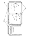
図4Bは、キャリア250によって使用するための例示的なトラック構造270を示す。この例では、キャリア250Aは、サンプルチューブを輸送し、キャリア250Bは、メイントラック272および/もしくはサブ経路274および274Aに沿ってチューブのラックを輸送する。経路276は、サンプルをキャリアに配置するか、またはこれらのキャリアからサンプルを取り出すために、オペレータによって使用され得る。
FIG. 4B shows an
図4Cは、例示的なトラック構造270のさらなる図を示す。この例では、サブ経路274は、免疫アッセイステーションとして機能し、サブ経路274Aは、臨床化学ステーションとして機能する。入力/出力レーン276には、サンプルの挿入もしくはメイントラック272からのサンプルを取り出すのにサンプルをバッファするために、サブ経路277および278を利用するサンプル取扱ステーション280がある。
FIG. 4C shows a further view of an
幾つかの実施形態においては、サンプルハンドラー280は、キャリア250Aおよび250Bへのサンプルもしくは他のペイロードを装填し、キャリア250Aおよび250Bからのサンプルもしくは他のペイロードを取り出すこともできる。これによって、分析器の需要がピークの間、大多数のキャリアをトラック277および278上で何も動かさずにいるのではなく、トラックシステム270におけるステーションによって現在使用されるペイロードを支持するために必要な量へと、キャリア数を減少させることを可能とする。その代わりに、オペレータは(本明細書で開示されたキャリアのない)サンプルトレイを入力/出力レーン276置く/取り出すことができる。これによって、システム全体のコストを減少させ、スループットを超える分析器の需要のピークの予測に基づくのではなく、分析器のスループットによって必要とされるキャリア数を決定することができる。
In some embodiments,
[知能キャリア]
幾つかの実施形態は、コストおよび複雑性を軽減するために、受動的パックもしくはトレイ(例えば、パックは、アクティブもしくは自律システム、電源、内蔵処理や制御がない単純なプラスチックもしくはゴムのブリックである)を利用することがあるが、幾つかの実施形態においては、(幾つかの実施形態においては、知能パックもしくはトレイを含むことができる)個々のキャリアに知能および自律性を組み込むために必要なさらなる複雑性およびコストが、ある利益をもたらす可能性がある。したがって、本発明の幾つかの実施形態は、摩擦ベーストラック上の受動的パックに勝る特定の改善を可能とするために、独立した知能キャリアを用いてもよい。例えば、従来技術のトラックシステムの欠点の一つとして、が、各決定点において、パックを回転させ、バーコードを光学的に読み取ることによって、トラックがパックを方向づけるための決定を行うということがある。回転および光学的な読み取りは比較的時間のかかるプロセスである。さらに、サンプルチューブがオペレータによってパックへと配置されるとき、システムはすでにサンプルチューブの識別に関する情報を有しているので、このプロセスは、余分なものである可能性がある。本発明の幾つかの実施形態は、キャリアを停止させたり回転させたり光学的に読み取るたりする必要なしにサンプルチューブの内容物を識別する(ならびに、任意でオートメーションシステムへとこの情報を通信する)ための手段を有するキャリアを含むことができる。
[Intelligent career]
Some embodiments provide passive packs or trays (eg, packs are simple plastic or rubber bricks without active or autonomous systems, power supplies, built-in processing or control to reduce cost and complexity. In some embodiments, it may be necessary to incorporate intelligence and autonomy into individual carriers (in some embodiments, it may include an intelligence pack or tray). Additional complexity and cost can provide certain benefits. Thus, some embodiments of the present invention may use independent intelligent carriers to allow certain improvements over passive packs on friction-based tracks. For example, one of the disadvantages of prior art track systems is that at each decision point, the truck makes a decision to orient the pack by rotating the pack and optically reading the barcode. . Rotation and optical reading are relatively time consuming processes. Furthermore, this process may be redundant because the system already has information regarding the identification of the sample tube when the sample tube is placed into the pack by the operator. Some embodiments of the present invention identify the contents of the sample tube (and optionally communicate this information to an automation system) without having to stop, rotate or optically read the carrier. A carrier having means for providing can be included.
例えば、キャリアは、ペイロードのバーコードを自動的に読み取るための内蔵光学リーダを含むことができる。キャリアが内蔵の処理機能を有する場合には、スキャン結果は、その後、キャリアのメモリに格納することができる。あるいは、キャリアへサンプルを配置するときにオペレータによって操作されるハンドバーコードリーダなどの外部ソースが、RF信号または一時的な電気接触もしくは光学通信を利用した通信プロトコルなどの他の既知の手段を介して、ペイロードのバーコード情報をキャリアへと通信することができる。幾つかの実施形態においては、ペイロードとキャリアの関連付けは、キャリアの外部に格納することができ、キャリアの情報は、RF、光学、もしくは近距離通信で、キャリアによってシステムへと伝送することができ、システムがキャリアおよびペイロードをルーティングするか追跡することに役立つようにする。その後、ペイロード固有のバーコードを読み取るのではなく、キャリアによって、もしくはキャリアを識別することによってルーティングの決定が行われる。 For example, the carrier can include a built-in optical reader for automatically reading the barcode of the payload. If the carrier has a built-in processing function, the scan results can then be stored in the memory of the carrier. Alternatively, an external source, such as a hand bar code reader operated by the operator when placing the sample on the carrier, via an RF signal or other known means such as a communication protocol utilizing temporary electrical contact or optical communication Thus, the barcode information of the payload can be communicated to the carrier. In some embodiments, the payload-carrier association can be stored outside the carrier, and the carrier information can be transmitted to the system by the carrier over RF, optical, or near field communication. To help the system route or track the carrier and payload. A routing decision is then made by carrier or by identifying the carrier, rather than reading the payload specific barcode.
処理機能および/もしくはセンサ機能を個々のキャリアに移すことによって、キャリアは、トラックシステムを通して、それ自身のルーティングにアクティブかつ知能的に関与することができる。例えば、個々のキャリアが、自律作動性能もしくはトラックとの通信のいずれかによって互いに独立して動くことができる場合、ある性能の利点を実現することができる。 By transferring processing functions and / or sensor functions to individual carriers, the carriers can actively and intelligently participate in their own routing through the track system. For example, certain performance advantages can be realized if individual carriers can move independently of each other either by autonomous performance or by communication with a truck.
キャリアが独立して移動させることによって、キャリアは、トラック周囲をより迅速に動くことができる。キャリアの動きに対する一つの制限として、キャリアが蓋のないチューブのサンプルをこぼさないようにすべきことがある。制限要因となるのは、通常、直線におけるキャリアの速度ではなく、サンプルをはね散らす可能性のある、(加速、減速もしく方向転換中の)キャリアにかかる加速度および加加速度(jerk)である。従来技術の摩擦ベースのトラックシステムでは、トラック全体が動くことでパックにかかる加速度および加加速度が閾値量を超えることを防止するためにトラックの速度は、一般的に、制限される。しかしながら、個々のキャリアに応じて独立して動作する区間、もしくは独立した作動性能を有する個々のキャリアを有するトラックシステムを利用することによって、平均速度が従来のトラックの速度よりも速くなることを可能にする一方で、任意のキャリアの加速度を、加速/減速および加加速度を制限するために調整することができる。キャリアの最高速度を制限しないことによって、キャリアは、必要に応じて各トラック区間上で加速し続けることができ、結果としてトラック周囲の平均速度が実質的により速くなる。これによって、キャリアが分析器の1機械サイクルよりも短期間でトラックシステム全体を移動することを補助することができる。これらの機械サイクルは、例えば、20もしくは40秒とすることができる。 By moving the carrier independently, the carrier can move around the track more quickly. One limitation to carrier movement is that the carrier should not spill sample in a tube without a lid. The limiting factor is usually not the velocity of the carrier in a straight line, but the acceleration and jerk on the carrier (acceleration, deceleration or turning) that can splash the sample. . In prior art friction-based track systems, the speed of the track is generally limited to prevent the acceleration and jerk applied to the pack from exceeding the threshold amount due to movement of the entire track. However, the average speed can be higher than the speed of conventional trucks by utilizing a track system with sections that operate independently according to individual carriers, or individual carriers with independent operating performance On the other hand, the acceleration of any carrier can be adjusted to limit acceleration / deceleration and jerk. By not limiting the maximum speed of the carrier, the carrier can continue to accelerate on each track segment as needed, resulting in a substantially higher average speed around the track. This can help the carrier move through the entire track system in less than one machine cycle of the analyzer. These machine cycles can be, for example, 20 or 40 seconds.
同様に、知能キャリアは、それ自身のアイデンティティおよびそのペイロードのアイデンティティを知ることができる。これによって、個々の決定点において、キャリアがルーティング決定プロセスにアクティブに関与するかまたは支援することを可能にする。例えば、決定点(例えば、スイッチ、交差点、分岐合流点、分岐点(fork)など)に到達すると、キャリアは、RFもしくは近距離通信を介して、トラックもしくは任意のスイッチング機構(もしくは、ペイロードアイデンティティに基づいてキャリアが決定した目的ルート)へと、自身のアイデンティティおよび/もしくはそのペイロードのアイデンティティを通信することができる。この場合、キャリアはバーコードスキャンのために決定点で停止する必要がない。その代わりに、キャリアは、減速さえすることなく進行し続けることができ、キャリアは、リアルタイムでルーティングされることができる。さらには、キャリアが決定点に物理的に到着する前に、キャリアがどこに進んでいるかを認識しているか、または、(キャリアがどこに進もうとしているかをトラックが認識するように)トラックへとそのアイデンティティを通信していれば、キャリアが方向転換する場合でもキャリアを決定点の前で減速させることができる。一方、キャリアが決定点において方向転換する必要がない場合、キャリアがトラックの決定点もしくは曲線区間で方向を変えなければ、キャリアによって運搬されるサンプルにはコーナリング力が発生しないのでキャリアはより速い速度で進み続けることができる。 Similarly, an intelligent carrier can know its own identity and its payload identity. This allows the carrier to actively participate or assist in the routing decision process at individual decision points. For example, upon reaching a decision point (eg, switch, intersection, branch junction, fork, etc.), the carrier can either track or any switching mechanism (or payload identity) via RF or near field communication. The identity of the payload and / or its payload can be communicated to the destination route determined by the carrier. In this case, the carrier need not stop at the decision point for barcode scanning. Instead, the carrier can continue to progress without even slowing down, and the carrier can be routed in real time. Furthermore, before the carrier physically arrives at the decision point, it knows where the carrier is going, or to the track (so that the truck knows where the carrier is going) If the identity is communicated, the carrier can be decelerated before the decision point even if the carrier changes direction. On the other hand, if the carrier does not need to change direction at the decision point, the carrier will move at a faster speed because no cornering force is generated in the sample carried by the carrier unless the carrier changes direction at the decision point or curve section of the track You can continue on.
知能キャリアは、内蔵処理およびセンサ性能も含むことができる。これによって、トラックによって方向づけられるのではなく(幾つかの実施形態においては、中央コントローラが実行されるべきルーティング命令をキャリアへと送信するが)、トラック上のどこにあるか、ならびにどこに行く必要があるかをキャリアが決定することを可能とする。例えば、キャリアの位置を決定するために、トラック内の位置の符号化もしくはマーカをキャリアによって読み出すことができる。キャリアがトラックを移動するとき、キャリアに対して参照点を提供するために、絶対位置情報がトラック表面上に符号化される。この位置符号化は、多くの形式をとり得る。トラックは、トラックの現在の区間を示す光学マーカで符号化されてもよいし(例えば、仮想のハイウェイ表示など)、トラックの区間内の特定の絶対位置の光学符号化をさらに含んでもよい(例えば、仮想のマイルマーカなど)。位置情報は、絶対位置マーク間のマーキングで符号化することもできる。これらは、キャリアがその現在の軌道を計算する支援のための同期情報を提供することができる。光学符号化方式は、当業者に既知の任意の適切な形式をとることができる。符号化スキームによって使用されるこれらのマークは、ロータリエンコーダにあるようなバイナリ位置符号、ある位置においてトラックに配置されたLEDなどの光学ランドマーク、バーコード、QRコード(登録商標)、データマトリクス、反射的ランドマークなどを含んでもよい。一般的位置情報は、RF/無線手段を介してキャリアへと伝送することもできる。例えば、トラック内のRFIDマーカは、トラックの所定の部分に入ったことをキャリアに警告するために、キャリアに近距離通信を提供することができる。幾つかの実施形態においては、トラック周囲もしくはトラック近傍のローカル送信機は、キャリアがその位置を決定することを可能にするために、GPS様位置情報を提供することができる。あるいは、ホール効果センサもしくはカメラなどのトラック内のセンサは、個々のキャリアの位置を決定し、キャリアにこの情報を中継することができる。 Intelligent carriers can also include built-in processing and sensor performance. This is not directed by the track (in some embodiments the central controller sends a routing instruction to be executed to the carrier), but where on the track as well as where it needs to go Allows the carrier to decide. For example, in order to determine the position of the carrier, the encoding or marker of the position in the track can be read by the carrier. As the carrier moves across the track, absolute position information is encoded on the track surface to provide a reference point for the carrier. This position encoding can take many forms. The track may be encoded with an optical marker that indicates the current section of the track (eg, a virtual highway display) or may further include an optical encoding of a particular absolute position within the section of the track (eg, Virtual mile marker). The position information can also be encoded by marking between absolute position marks. These can provide synchronization information to assist the carrier in calculating its current trajectory. The optical encoding scheme can take any suitable form known to those skilled in the art. These marks used by the encoding scheme are binary position codes, as in a rotary encoder, optical landmarks such as LEDs placed in a track at certain positions, bar codes, QR codes, data matrices, It may include reflective landmarks and the like. The general location information can also be transmitted to the carrier via RF / wireless means. For example, an RFID marker in a track can provide near field communication to the carrier to alert the carrier that a predetermined portion of the track has been entered. In some embodiments, a local transmitter around or near the track can provide GPS-like location information to allow the carrier to determine its location. Alternatively, sensors in the track, such as Hall effect sensors or cameras, can determine the position of individual carriers and relay this information to the carriers.
同様に、キャリアは、位置決定するために蓄積されるデータを提供する、相対的な動きを示すセンサを有し得る。例えば、キャリアは、相対的位置を推定するために使用することができるジャイロスコープ、加速度計、または速度もしくは加速度を決定するためにキャリアが移動するにつれてスペックルパターンを観察する光学センサを有してもよい。 Similarly, the carrier may have a relative movement sensor that provides data that is accumulated for positioning. For example, the carrier has a gyroscope that can be used to estimate the relative position, an accelerometer, or an optical sensor that observes a speckle pattern as the carrier moves to determine velocity or acceleration Also good.
キャリアは、どこにそのキャリアがあるか、およびトラックに対するその動きを認識することができるため、その行き先がわかる限り、キャリアは実質的に自身を駆動することができる。キャリアのルーティングは、種々の実施形態によって多くの異なる方法で提供され得る。幾つかの実施形態においては、キャリアがサンプルを装填されると、システムはキャリアに行先の分析器ステーションを伝えることができる。キャリアが自律ルーティング機能を有する実施形態においては、この情報は行先ステーションの識別と同じくらい単純であってよい。また、この情報は、個々のトラック区間の特定の経路およびキャリアが移動するはずの決定点を識別するルーティングリストなどの詳細情報であってもよい。ルーティング情報は、RF通信、近距離/誘導通信、電子的接触通信、もしくは光通信などの、本明細書に記載の任意の通信方法を介してキャリアに伝送することができる。 Since the carrier can recognize where the carrier is and its movement relative to the track, as long as the destination is known, the carrier can substantially drive itself. Carrier routing may be provided in many different ways according to various embodiments. In some embodiments, once the carrier is loaded with a sample, the system can communicate the destination analyzer station to the carrier. In embodiments where the carrier has autonomous routing capabilities, this information may be as simple as identifying the destination station. Further, this information may be detailed information such as a routing list for identifying a specific route in each track section and a decision point where the carrier should move. The routing information can be transmitted to the carrier via any communication method described herein, such as RF communication, near field / induction communication, electronic contact communication, or optical communication.
例示的な一実施形態においては、オペレータがサンプルチューブのバーコードをスキャンして、キャリア内へ配置するとき、システムは、キャリアのアイデンティティを判定して、サンプルのアイデンティティとキャリアのアイデンティティを整合する。システムはその後、サンプルが分析器内でどの試験を受ければならないかを決定するために、サンプルの記録を探す。スケジューラは、その後、個々の試験ステーションによってどの試験が行われるか、ならびにサンプルがいつ分析用の各試験ステーションに到達するべきかの選択を含むサンプルに対する試験リソースの割り当てを行う。システムはその後、キャリアがどこに行く必要があるのか、ならびに、任意で、キャリアがいつ行く必要があるのかおよび/もしくはキャリアがいつ到着する必要があるのかをそのキャリアに知らせるために、キャリアに対してこのスケジュール(もしくはスケジュールの一部)を通信することができる。 In one exemplary embodiment, when an operator scans a barcode on a sample tube and places it in the carrier, the system determines the carrier identity and matches the sample identity with the carrier identity. The system then looks for a record of the sample to determine which tests the sample must undergo in the analyzer. The scheduler then assigns test resources to the samples, including selection of which tests are performed by the individual test stations and when the samples should reach each test station for analysis. The system then asks the carrier to know where the carrier needs to go and, optionally, when the carrier needs to go and / or when the carrier needs to arrive. This schedule (or part of the schedule) can be communicated.
一旦キャリアがトラックシステム上に配置されると、キャリアのルーティング機能および位置獲得システムは、キャリアがトラック上のどこにあるか、ならびにトラック上のどこに行く必要があるかをキャリアに決定させることを可能にする。キャリアがトラックを移動していくと、キャリアは個々の決定点に到達し、必要に応じ、メイントラックに沿って、またはサブ経路に沿った方向づけがなされる。各キャリアは互いに独立して動作するため、キャリアは、各決定点において必ずしも停止することなく、また待ち行列で他のキャリアを待つことなく、非常に迅速にこれを行うことができる。これらのキャリアは迅速に移動するため、トラックのメイン区間上の混雑は少なく、トラック内の決定点もしくはコーナー(例えば、キャリアがサンプルに過度の力がかかることを回避するために減速する区間)における衝突もしくは渋滞のリスクは減少する。 Once the carrier is placed on the track system, the carrier routing and location acquisition system allows the carrier to determine where the carrier is on the track and where it needs to go on the track. To do. As the carrier moves through the track, the carrier reaches individual decision points and is directed along the main track or along the sub-path as required. Since each carrier operates independently of each other, the carrier can do this very quickly without necessarily stopping at each decision point and waiting for other carriers in the queue. Because these carriers move quickly, there is less congestion on the main section of the track, and at decision points or corners in the track (eg, sections where the carrier decelerates to avoid applying excessive force to the sample) The risk of collision or congestion is reduced.
推進力は、多くの方法でキャリアに対して提供することができる。幾つかの実施形態においては、トラックは、各キャリアに対して個別化された推進力を提供することにアクティブに関与する。幾つかの実施形態においては、推進力は、キャリア内の一つ以上の磁石を推しだすトラックにおける電磁コイルによって提供される。この推進力を提供するための例示的システムは、MagneMotion,Inc.によって提供されるトラックシステムであって、それは、MagneMotion,Inc.に譲渡された米国特許出願整理番号2010/0236445にある線形同期モータ(LSM)の記載によって概ね理解できる。この磁気的作動システムを利用するこれらの従来のシステムは、本明細書に記載のキャリアに組み込まれた知能を欠く受動的キャリアを含み、全てのルーティングおよび決定は中央コントローラによって行われ、ルーティングおよび識別プロセスに関与するアクティブキャリアを必要としない。 Propulsion can be provided to the carrier in a number of ways. In some embodiments, the truck is actively involved in providing personalized propulsion for each carrier. In some embodiments, the propulsive force is provided by an electromagnetic coil in a track that thrusts one or more magnets in the carrier. An exemplary system for providing this propulsion is available from MagneMotion, Inc. The track system provided by MagneMotion, Inc. Can be generally understood by the description of a linear synchronous motor (LSM) in US Patent Application Serial No. 2010/0236445 assigned to. These conventional systems that utilize this magnetic actuation system include passive carriers that lack the intelligence built into the carriers described herein, and all routing and decisions are made by the central controller, routing and identification Does not require an active carrier involved in the process.
磁気的作動を利用する実施形態においては、電磁的コイルおよび磁石は、速度、加速度および加加速度の精密な制御で選ばれた方向へと個々のキャリアの一つ一つを推しだすためのLSMとして動作する。トラック上の各コイル(もしくは特定の場所のコイルのセット)が独立して動作できる場合、個々のキャリアに対して高度に局所化された推進力を与え、個々のキャリアがそれ自身個々に調整された加速度および速度で移動することが可能となる。コイル付近を通過する個々のキャリアの方向、速度、加速度および加加速度の精密な制御のため、キャリアに対して局在するコイルはいかなる瞬間にも作動させられる。 In embodiments utilizing magnetic actuation, the electromagnetic coils and magnets serve as LSMs to push out each individual carrier in a selected direction with precise control of velocity, acceleration and jerk. Operate. If each coil on a track (or a set of coils at a specific location) can operate independently, it will provide a highly localized propulsion for each carrier, and each carrier will be adjusted individually. It is possible to move at a high acceleration and speed. For precise control of the direction, velocity, acceleration and jerk of individual carriers passing near the coil, the coil localized to the carrier is activated at any moment.
幾つかの実施形態においては、トラックは局所的にカスタマイズ可能な摩擦トラックとして機能する多くの個々の統合可能なローラで構成されてもよい。トラックのうちの個々の短区間は独立して管理できるため、キャリア周囲のローラは、個別化された速度、加速度、および加加速度を提供するよう制御されてもよい。幾つかの実施形態においては、各キャリアに局所化された推進力をそれぞれ提供する他のアクティブトラック構造を使用することができる。 In some embodiments, the track may be composed of many individual integratable rollers that function as locally customizable friction tracks. Because individual short sections of the track can be managed independently, the rollers around the carrier may be controlled to provide individualized speed, acceleration, and jerk. In some embodiments, other active track structures can be used that each provide localized propulsion for each carrier.
幾つかの実施形態においては、トラックは、ほぼ受動的であって、一次元でキャリアを誘導するためにフロア、壁、レールもしくは他に該当するキャリアの作動に対する制限をする。これらの実施形態においては、推進力はキャリア自身によって提供される。幾つかの実施形態においては、各個々のキャリアは、トラックとキャリアの間の自己推進摩擦ベースの推進力を提供するためのホイールを駆動する、一つ以上の内蔵モータを有する。従来の摩擦トラックとは異なり、トラックがコンベヤである場合、駆動されたホイールを有するキャリアは、独立してトラックを移動し、個々に加速/減速することができる。これによって、各キャリアは個々に調整されたルートに沿ってトラックを移動するとともに、そのペイロードに及ぼされる力を制御するために、自身の速度、加速度および加加速度をいかなる瞬間にも制御することができる。幾つかの実施形態においては、永久磁石がトラック内に備えられ、キャリア内の電磁石はキャリアを前方に推しだすように動作し、それによってLSMとしての役割を果たし、キャリアは駆動磁気力を提供する。他の受動的トラック構成、例えば、キャリアがウォータージェットなどを介して自律的に浮遊して動くことを可能にする流体トラック、トラックに備えられた(例えば、局所化されたエアホッケーテーブルのような役割を果たす)空気ポケット上にキャリアを浮遊させる低摩擦トラック、もしくは個々のキャリアがトラックを移動するときに個別化された推進力を与える他の構成なども考えられる。 In some embodiments, the track is generally passive and limits the operation of the carrier on the floor, walls, rails or others to guide the carrier in one dimension. In these embodiments, the propulsion is provided by the carrier itself. In some embodiments, each individual carrier has one or more built-in motors that drive wheels to provide self-propelled friction-based propulsion between the track and the carrier. Unlike conventional friction tracks, if the track is a conveyor, the carrier with driven wheels can move the track independently and accelerate / decelerate individually. This allows each carrier to move along the individually tuned route and to control its speed, acceleration and jerk at any moment to control the forces exerted on its payload. it can. In some embodiments, a permanent magnet is provided in the track, and the electromagnet in the carrier operates to push the carrier forward, thereby serving as an LSM, where the carrier provides the driving magnetic force. . Other passive track configurations, such as fluid tracks that allow carriers to float and move autonomously via water jets, etc., are provided in tracks (such as localized air hockey tables) Other configurations are possible, such as a low friction track that floats a carrier over the air pocket (which plays a role), or other configurations that provide individualized propulsion as individual carriers move across the track.
図5は、例示的な知能自律キャリア300の制御システムおよびセンサの最上位システム図を示す。キャリア300は、キャリアを操作するために必要とされる操作案内、保守、作動およびセンサ動作を扱うための十分な処理力を含むマイクロコントローラ301によって制御される。従来技術の受動的キャリアとは異なり、キャリアはアクティブであって内蔵の電子機器を含むため、内蔵の電力ステーションも含む。このステーションの詳細は、本発明の異なる実施形態によって変わる。幾つかの実施形態においては、電力システム303は、キャリアが動作すると充電されるようなバッテリを含む一方で、他の実施形態においては、バッテリは交換式であるか、またはキャリアが動作していないときに手動で充電することができる。電力システム303は、バッテリを維持するために必要な充電電子機器を含むことができる。他の実施形態においては、電力システム303は、地下鉄車両もしくは模型電車が電力を受信するのとほぼ同じ方法で、トラック自体から電位を獲得するための誘導もしくは電子接触機構によって充電されうるキャパシタを含む。
FIG. 5 shows a top level system diagram of an exemplary intelligent
マイクロコントローラ301はシステムメモリ304と通信する。システムメモリ304は、データおよび命令メモリを含んでもよい。メモリ304内の命令メモリは、キャリアを操作するために十分なプログラム、アプリケーションもしくは命令を含む。これは、センサ取扱アプリケーションと同様に操作案内手順を含んでもよい。メモリ304内のデータメモリは、現在位置、速度、加速度、ペイロードの内容、操作案内計画、キャリアもしくはペイロードのアイデンティティ、もしくは他の状態情報についてのデータを含むことができる。キャリア300内に内蔵メモリを含むことによって、キャリアは、現在の状態を記録したり、トラック周囲を知的にルーティングしたりトラックもしくは他のキャリアに状態情報を伝えるために情報を利用したりすることができる。
Microcontroller 301 communicates with
マイクロコントローラ301は、モーションシステム305、センサ312、313および314、通信システム315、状態ディスプレイ316ならびにサンプルセンサ317の操作を担当している。これらの周辺機器は、バス310を介してマイクロコントローラ301によって操作される。バス310は、複数の周辺機器と通信することが可能なCANバスなどの任意の標準バスであるか、または、個々の周辺機器への個々の単一経路を含み得る。周辺機器は、それ自身の電源もしくは共通の電力システム303を使用することができる。
The microcontroller 301 is responsible for operating the
モーションシステム305は、本明細書に記載のモーションシステムのうちのいずれかを操作するために必要な制御論理を含むことができる。例えば、駆動されたホイールを利用する実施形態においては、モーションシステム305はモータコントローラを含み得る。他の実施形態においては、モーションシステム305は、キャリア300に推進力を与えるために必要な任意のアクティブトラックシステムと通信するために必要な論理を含むことができる。これらの実施形態においては、モーションシステム305は、マイクロコントローラ301によって実行され、トラックと通信するために通信システム315を利用するソフトウェアコンポーネントであってもよい。モーションシステム305によって制御されるモータ、アクチュエータ、電磁石などのデバイスは、これらのデバイスがキャリアに内蔵される実施形態においては、電力システム303によって作動する。LSMがトラック内のコイルにエネルギーを供給することによって推進力を提供する実施形態などの幾つかの実施形態においては、外部電源もまた、電力を供給することができる。幾つかの実施形態においては、モーションシステム305は、推進力を提供するためにキャリア内外のデバイスを制御する。幾つかの実施形態においては、モーションシステム305は、推進力を調整するために、トラック内の近傍のコイルにエネルギー供給を要求したり、もしくはローカルローラの移動を要求したりすることによって、トラック内のコントローラなどの他のコントローラとともに動作する。これらの実施形態においては、モーションシステム315は、キャリアを動かすために通信システム305と連携することができる。
The
キャリア300は、一つ以上のセンサを含むことができる。幾つかの実施形態においては、キャリア300は、衝突検出システム312を含む。衝突検出システム312は、キャリアの前または後ろにキャリアが別のキャリアに近づいているかどうかを判定するためのセンサを含むことができる。例示的な衝突検出センサとして、IR測距装置、磁気センサ、マイクロ波センサもしくは光検出器があり得る。多くの従来技術のパックは円形であるが、キャリア300には前方部分および後方部分を有する方向性があってもよい。方向性のある形状を有することによって、キャリア300は、前方衝突検出器および後方衝突検出器を含むことができる。
The
幾つかの実施形態においては、衝突検出情報は、通信システム315を介して受信される情報を含むことができる。例えば、幾つかの実施形態においては、トラックの中央コントローラは衝突を防止するために、トラック上のキャリアの位置および速度を観察して、衝突条件を判断し、キャリアに対して更新した指示を送信することができる。幾つかの実施形態においては、近接するキャリアは、互いの位置をピアツーピア方式で通信することができる。これによって、他のキャリアから受信されたリアルタイム位置情報に基づいて、キャリアが個々に衝突のリスクを査定することが可能となる。キャリアが他のキャリアについての軌道情報を受信したり、近接するキャリアの軌道情報にアクセスできる集中管理コントローラを用いたりして決定が行われるような実施形態においては、キャリアに方向性がある必要がなく、また、キャリアの任意の方向付けに依存しないセンサもしくは受信機を含むことができることを理解されたい。
In some embodiments, the collision detection information can include information received via the
キャリア300は位置デコーダ313も含むことができる。このセンサは、本明細書に記載されるようにキャリアの位置を推定することができる。例えば、位置デコーダ313は、トラック内のランドマークを識別したりトラック内の光符号化を観察したりするためのカメラもしくは他の光学手段を含むことができる。幾つかの実施形態においては、位置デコーダ313は、慣性センサ、磁気センサ、もしくはキャリアの現在位置、方向、速度、加速度および/もしくは加加速度を決定するために十分な他のセンサも含むことができる。幾つかの実施形態においては、位置デコーダ313のコンポーネントは、通信システムの一部として動作することができる。例えば、幾つかの実施形態においては、トラック内の光マーキングは、LCDもしくは電子インクディスプレイなどを介して電気的に書き換え可能であって、位置情報とともにルーティング命令を伝送するために中央コントローラによって使用できる。これらの実施形態においては、位置を決定するために使用されるイメージセンサは、ルーティング命令もしくはキャリアに通信される他のデータを受信するために使用することもできる。
The
キャリア300は、任意でバーコードリーダ314を含むことができる。バーコードリーダ314を備えている場合、キャリア300は、サンプルがキャリア上に装填されたとき、またはそれ以降の任意の時間に、そのペイロードのバーコードを観察することができる。これによって、サンプルチューブのバーコードをシステムに読みとらせるためにキャリアを個々の決定点で停止させる必要がなくなる。サンプルチューブのアイデンティティを読み取って格納することによって、もしくはこの情報をシステム全体へと伝送することによって、ルーティングの決定は決定点に到達する前に行うことができるためキャリアはより効率的にトラックシステムを移動することとなる。或いは、サンプルがキャリア上に置かれるときにサンプルのアイデンティティをシステムが認識している場合には、システムは、外部バーコードリーダを含み、通信システム315を介して記憶装置およびメモリ304用に、キャリアに対してペイロードのアイデンティティを伝送することができる。
The
通信システム315は、キャリアにオートメーションシステム全体と通信させるのに十分な任意の機構を含むことができる。例えば、これには、802.15.4、802.11の該当するバージョン、もしくは任意の標準もしくは専用ワイヤレスプロトコルなど既製の通信プロトコルを利用するワイヤレス通信用のXBee通信システムが含まれる。通信システム315は、RF通信プロトコルを操作するための送受信機およびアンテナおよび論理を含むことができる。幾つかの実施形態においては、通信システム315は、近距離通信、光通信、もしくは電気接触コンポーネントも含むことができる。キャリア300へと/キャリア300から通信システムを介して伝送される情報は、本出願を通して記載される。
The
幾つかの実施形態においては、キャリアは、状態ディスプレイモジュール316も含むことができる。状態ディスプレイモジュール316は、コントローラと、LCDパネルもしくは電子インクディスプレイなどの書き換え可能な電子ディスプレイを含むことができる。幾つかの実施形態においては、コントローラは、メモリのアドレス可能部分として扱われ、マイクロコントローラ301が状態ディスプレイ316を容易に更新することができる。
In some embodiments, the carrier can also include a
幾つかの実施形態においては、キャリアはサンプルセンサ317も含む。このセンサは、キャリアのチューブブラケット(チューブホルダとも称されうる)内の流体容器の有無を示すのに用いられる。幾つかの実施形態においては、これは、チューブによって押され、チューブがないときには押されない機械的モーメンタリスイッチである。この情報は、チューブの状態を決定するために使用することができ、状態ディスプレイモジュール316による状態情報の表示に役立たせることができる。
In some embodiments, the carrier also includes a
[ルーティングおよび配置]
分析器システム内の通過時間を迅速にするという要望によりルーティングは困難なものとなり得る。従来技術のシステムにおいては、サンプルは通常、各決定点で停止し、個別化され、スキャンされるので迅速なルーティングはそれほど重要ではない。これらシステムにおいては、ある決定点でのルーティング決定は、サンプルが停止している間に行われる。迅速なルーティング決定は概して望ましく、サンプルキャリアが決定点に到達する前にスイッチング決定をすることが求められることもある。さらには、キャリアが従来技術と比較して速い速度で移動するため、サンプルキャリアの即時の軌道の制御は、IVDサンプルがこぼれたり損傷したりすることを防ぐために、リアルタイム処理によって補助され得る。幾つかの実施形態においては、実質的に即時の軌道観察および制御は、リアルタイム制御を容易にするために各キャリア上で実施されるが、全体のルーティング決定は、一群のキャリアを管理する中央コントローラによって行われる。したがって、本発明の幾つかの実施形態においては、キャリアは、中央コントローラから全体的なルーティング命令を受信する半自律ロボットのように動作するが、実質的には自律して局所的に動作判断を行う。
Routing and placement
Routing can be difficult due to the desire to speed transit time in the analyzer system. In prior art systems, samples are typically stopped at each decision point, individualized, and scanned, so rapid routing is less important. In these systems, routing decisions at certain decision points are made while the samples are stopped. A quick routing decision is generally desirable and may require a switching decision before the sample carrier reaches the decision point. Furthermore, as the carrier moves at a faster speed compared to the prior art, immediate trajectory control of the sample carrier can be assisted by real-time processing to prevent the IVD sample from spilling or being damaged. In some embodiments, substantially immediate trajectory observation and control is performed on each carrier to facilitate real-time control, but the overall routing decision is a central controller that manages a group of carriers. Is done by. Thus, in some embodiments of the invention, the carrier behaves like a semi-autonomous robot that receives global routing instructions from a central controller, but is substantially autonomous and makes local motion decisions. Do.
図6に示された例示的なトラック400は、直線セグメントBおよびプルアウトセグメントG(例えば、試験ステーションを提供するセグメント)に決定点402を介して接続する第一のカーブセグメントAを含み、プルアウトセグメントGは分析器試験ステーション205Aおよびピペット420を提供する。セグメントBは、決定点404を介して直線セグメントCおよび分析器/試験ステーション205およびピペット422を提供するプルアウトセグメントHに接続する。セグメントCは、サンプル取扱ステーション205Cを提供する曲線セグメントDおよび分析器/試験ステーション205Bおよびピペット424を提供するプルアウトセグメントIに決定点406を介して接続する。セグメントDは直線セグメントEおよびプルアウトセグメントIの他端に決定点408を介して接続する。即ち、決定点406と408の間には、異なる経路であるセグメントDおよびIが存在する(ここでセグメントIは、ピペット424と接触するサンプルを送達するのに使用されるプルアウトである)。セグメントEは、決定点410を介して、直線セグメントFおよびプルアウトセグメントHの他端に接続する。セグメントFは、決定点412を介して、カーブセグメントAおよびプルアウトセグメントGの他端に接続する。幾つかの実施形態においては、トラック400は、決定点402および412においてキャリアを追加もしくは除去するために用いられる入力および出力レーンJおよびKを含む。中央管理プロセッサ440は、キャリアによって運搬されるサンプルもしくは他のペイロードおよびシステムによってこれらのサンプルに実施される必要のあるアッセイのアイデンティティとともに、キャリアおよびトラックの状態情報を利用する。
The
幾つかの実施形態においては、決定点402−412は、適切な行先セグメントを選択するためにキャリア430が進むトラック内の受動的分岐点である。他の実施形態においては、決定点402−412は、キャリア430もしくは中央管理プロセッサ440によって制御されるアクティブ分岐点である。幾つかの実施形態においては、決定点402−412は、RFもしくは近距離通信などを介して、キャリア430による要求に応答する電磁的に制御されたスイッチである。幾つかの実施形態においては、これらの電磁的に制御されたスイッチは、キャリアが一度ルーティングされたらスイッチが戻るデフォルト位置(直線部分など)を有する。決定点用のデフォルト位置を利用することによって、キャリアは、その決定点において切り替えられる必要がない限り、各決定点において位置を要求する必要がない。
In some embodiments, decision points 402-412 are passive branch points in the track that
例示的なスケジュールにおいて、中央管理プロセッサ440は、ピペット420の到達範囲内にキャリア430およびそのペイロードを配置するために、第一のルートをキャリア430に割り当てる。キャリア430は、セグメントJに沿って決定点402へと移動し、かつ、ピペット420にアクセス可能な位置で停止するようにセグメントG上を移動するように命令される。幾つかの実施形態においては、キャリア430は、命令を受信して、決定点402に到達するために使用する方向および軌道を決定するために、キャリアの現在位置および軌道を決定する。キャリア430は、セグメントG上へと決定点402において右へ急旋回をするであろうことを考慮に入れることもできる。幾つかの実施形態においては、決定点402は、キャリア430の制御下で動作することができるスイッチング機構をトラック内に含む。これらの実施形態においては、キャリア430は、セグメントG上への切り替えを要求するために、決定点402へ近付くときにトラックと通信する。他の実施形態においては、キャリア430は、トラック内へと一体化された外部ゲートの補助なしで、決定点402においてキャリア430を右折させセグメントG上へ行かせる操縦機構(移動可能なガイドホイール、指向性磁石、非対称ブレーキなど)を有してもよい。これらの実施形態においては、キャリア430は、セグメントG上へ方向を変えるために、決定点402において操縦機構を使用する。
In the exemplary schedule,
キャリア430は、光符号化などトラック内の符号化もしくはRFIDタグを読みとることによって、キャリアのおおよその位置、つまり区間Jなどのキャリアの現在のトラック区間を決定することができる。幾つかの実施形態においては、キャリア430は、トラックシステム400内のキャリアの位置を決定するために複数の手段を使用する。例えば、RFIDタグはどのトラックセグメントにキャリア430が位置するのかを概して判定するために使用することができるのに対し、光符号化もしくは他の精密な符号化は、当該トラックセグメント内の位置を判定するために用いられる。符号化の変化(例えば、位置情報からの派生物)を観察することで、この符号化を速度、加速度もしくは加加速度を決定するためにも使用することができる。
The
図5における内蔵制御システムに示されるように、キャリア430は、中央管理プロセッサ440によって受信された明示的な命令、もしくはメモリ304内の内蔵データベース内の該当ルートを探すことのいずれかによって、行先区間へと適切なルートを決定するために、現在のトラック区間の識別を利用することができる。幾つかの実施形態においては、キャリア430は、メモリ304内のキャリア430のメモリに格納されたマップに基づいて、区間Jから区間Gへと如何にして到達するかを理解する。このマップは、単純なルックアップテーブルもしくは、各ノードが対応する決定点で関連付けられている、もしくはその逆のトラック区間のツリーを含むことができる。例えば、キャリアが現在トラック区間Jにあることを識別すると、内蔵データベースは、決定点402へと進み区間G上へと右に切り替えられるようにキャリア430へと知らせることができる。
As shown in the embedded control system in FIG. 5, the
[線形ランダムアクセス待ち行列]
分析器内のルーティングおよびサンプル処理は、オートメーションシステム内のある位置に配置された線形待ち行列から恩恵を得ることができる。これらの線形待ち行列は、必要とされる空間の大きさを大きく増やすことなく、FIFOおよびランダムアクセス機能の双方を提供することができる。
[Linear random access queue]
Routing and sample processing within the analyzer can benefit from linear queues located at certain locations within the automation system. These linear queues can provide both FIFO and random access functions without greatly increasing the amount of space required.
図7は、トラック区間284および284A上で線形ランダムアクセスを利用する例示的なオートメーションシステム290を示す。オートメーションシステム270と同様に、オートメーションシステム290はトラック区間284および284Aなどのサブ経路を有するメイントラックとして機能するトラック区間を利用する。トラック区間284および204Aは、分析器内でモジュールへの局所的なアクセスができるように、サイドカーとして機能する。これらのトラック区間は、システム内のモジュールに到達するためにキャリア250Aの輸送手段を提供する。モジュールへのアクセスができるようにするため、これらのトラック区間は予め決められた長さを有する。トラック区間に対応するモジュールがバッファもしくは待ち行列を必要とする場合、この長さがあることによってこれらのトラック区間は複数のキャリアを物理的にバッファするのに適切なものとなる。通常、トラック区間上でのバッファリングは、FIFO待ち行列の固有の制限の全てを伴うFIFO待ち行列となる。しかしながら、本発明の実施形態は、トラック区間内でキャリアを再順序付けすることができるようにトラック区間を利用するのに便利な格納位置を用いることができる。これによって、トラック区間自体を待ち行列が占める空間に利用しながら、ランダムアクセス待ち行列の利点が得られる。
FIG. 7 shows an
オートメーションシステム290は、二つの例示的な格納位置を含む。トラック区間284は、位置292を介したローカルモジュールへのアクセスを提供する。位置292は、モジュール上のピペットからアクセス可能である。位置292にサンプルキャリアを置くことで、運搬される所定量のサンプルが吸引できる。ローカルトラック区間284は、位置292に到達するためにサンプルキャリアの物理待ち行列を提供することができる。格納位置294は、トラック区間284のメイン部分からサンプルキャリアを一時的に抜き取るために用いられる。一つまたは複数のサンプルを格納位置294内に格納するために、待ち行列の一部を移動することによって、任意のサンプルを線形待ち行列内から選択することができる。これによって、少なくともサンプルの一部に対してランダムアクセスを提供することができる。あるサンプルが格納位置294に格納されると、待ち行列内の一つ以上のキャリアが格納位置294に対して動かされ、位置294内に格納されたサンプルを、サンプルを抜き取った元の位置とは異なる待ち行列内の位置においてトラック区間284上の待ち行列に再導入することができるようになる。このように、格納位置294はトラック区間284上の線形待ち行列内のサンプルを再順序付けするために使用できる。FIFO方式待ち行列を選択的に再順序付けすることによって、サンプルに対するランダムアクセスを提供することができる。
The
トラック区間284Aは、物理待ち行列内のサンプルに対してランダムアクセスを提供するための格納位置を用いた別の手法を説明するよい例となる。この実施例においては、位置298は、ローカルモジュールのピペットからアクセス可能である。サンプルを位置298に動かすことによって、所定量のサンプルが吸引できる。位置298は、トラック区間284Aのメイン部分上にない。むしろ、位置298は、格納位置296内にある。待ち行列内のサンプルに対するランダムアクセスを格納位置296へとシフトするためにトラック区間284A上の待ち行列内のサンプルは前後に動き、格納回転内の位置298におけるサンプルに対するアクセスを提供する。
トラック区間284および284A上の格納位置の例示的な実装は、ローカルモジュールによって使用される、サンプルに対するFIFOおよびランダムアクセスの双方を提供することができる。さらに、格納位置を用いる手法では、ローカルモジュールにローカル待ち行列内のサンプルを制御させて再順序付けさせるため、多くの異なるタイプのトラックでもこの手法を用いることができる。例えば、トラック区間284は、摩擦トラック、磁気トラック、受動的トラック、もしくはキャリア上のサンプルを待ち行列内で前後に動かすのに適した他のトラックであってもよい。本発明の幾つかの実施形態は、サンプルをトラック区間内で前または後に動かすための双方向の機能性を提供する待ち行列用トラック区間を利用する。さらには、キャリアおよびペイロードのタイプは、本明細書に記載の任意の適切なキャリアおよびペイロードであってよい。適切なキャリアには、例えば、個々のサンプルを運搬するキャリア250Aがある。適切なキャリアには、ペイロードとして試薬を運搬することができるキャリア250Bもある。ローカルトラック区間内の待ち行列は、サンプルおよび試薬の双方もしくは他のペイロードを含むことができる。例えば、待ち行列がサンプルキャリアと試薬キャリアの混合であることもある。この場合、単一のアッセイが実施されるときには、一つのピペットが試薬およびそれに対応するサンプルにアクセスすることを可能とすることができる。待ち行列内のランダムアクセスを提供することによって、サンプルもしくは試薬がローカルトラック区間に到達する順序をこれらのサンプルもしくは試薬が使用される順序に一致させる必要がない。
Exemplary implementations of storage locations on
図8は、従来技術のサイドカーにおける例示的なFIFO待ち行列を示す。サンプルは、メイントラック502を移動するか、または、ローカル試験モジュールとの接触するのためにサイドカー504へと方向づけることができる。ピペット510は、サイドカー上のサンプルに対するアクセスを可能とするために提供される。第一の状態500においては、ローカル待ち行列520は、サンプルA、BおよびCを含む。待ち行列520は、FIFO待ち行列である。サンプルAが吸引され、続いてサンプルBが吸引され、続いてサンプルCが吸引される。この状態は、全サンプルが同一優先度であって、ローカルモジュールが各サンプルに対して連続して準備される限り、適切である可能性がある。
FIG. 8 shows an exemplary FIFO queue in a prior art sidecar. The sample can be directed to the
しかしながら、この手法は、STATサンプルが到達すると問題が生じる可能性がある。状態501に示されるように、STATサンプルがサイドカー504上に方向づけられると、それが優先される。ランダムアクセスが提供されないため、待ち行列520は、メイントラック上にフラッシュされなければならない。本実施例においては、待ち行列520がメイントラック502上に放出されたときに、サンプルDは、既にメイントラック上にあった。示されるように、グループ522はいまやサンプルBおよびCの間にサンプルDを有する。したがって、いったんサンプルA、BおよびCがトラック周囲を回って戻りサイドサイドカー504上に再度現れ、サンプルDがサイドカー504上に方向づけられると、それらは元の順序のとおりではなくなっている可能性がある。さらには、サンプルA、BおよびCがサイドカー504へと戻るにはローカル分析器モジュールのサンプルサイクル数回分かかる可能性がある。結果として、ローカル分析器モジュールに無駄なダウンタイムを生じる可能性がある。さらには、特定の試薬がサンプルAに準備された場合、サンプルAがサイドカー504に戻る前にその試薬を準備するリソースが他のサンプルによって使用されると、それらの試薬は、無駄になる可能性がある。
However, this approach can cause problems when STAT samples arrive. As shown in
図9は、カルーセル524によって提供されるランダムアクセス待ち行列の従来技術の手法を示す。この例においては、カルーセルは小さいが、カルーセルは、カルーセル内の位置数が増加すると急速に面積を拡大する。これは、カルーセル内の利用可能な位置の量を制限し、サイドカー504上の待ち行列のサイズを制限する可能性がある。状態512においては、サンプルA、BおよびCは、メイントラック502外のサイドカー504上へ方向づけられ、カルーセル524へと配置された。サンプルAは、ピペット510に接触する。状態513においては、STATサンプルがサイドカー504上に到達するとき、サンプルAがピペット510との接触を完了する間に、STATサンプルはカルーセル524内の位置へと配置することができる。いったんピペット510がサンプルAからの吸引を完了すると、状態514において、サンプルAはサイドカー504を介してカルーセルからメイントラック502へと放出される。カルーセル524はカルーセル内に保持されたサンプルに対するランダムアクセスを提供するので、STATサンプルをピペット510と接触させるためにカルーセルが回転する間に、サンプルA、BおよびCは、カルーセル内に残存することができる。カルーセル524は、複雑性およびコストを追加し、分析器内では貴重である空間を占めてしまうことになる。
FIG. 9 shows a prior art approach for a random access queue provided by
図10Aは、FIFO待ち行列540内でサンプルに対するランダムアクセスを提供するために、トラック530に対してアクセス可能な格納位置534を利用する本発明の一実施形態の動作例を示す。ここで、ピペット510は、位置532においてトラック530にアクセスできる。状態544においては、待ち行列540は、A,B,C,Dの到着順序である。サンプルは右側から到着して、左側へ行く。状態545においては、サンプルAは、ピペット510に所定量のサンプルAを吸引させるために位置532へと動かされる。一方、待ち行列を処理するコントローラは、サンプルBにアクセスする前に、サンプルCにアクセスすることが望ましいことを決定する。したがって、サンプルBは、位置534へと方向づけられて格納される。これによって、サンプルCおよびDで構成されるグループ541が残る。状態546においては、ピペット510がサンプルAを終了した後サンプルCにアクセスできるように、サンプルCは格納位置534を通り越すよう方向づけられる。一方、サンプルBは格納位置534を出てトラック530上に戻りサンプルCおよびDの間へと方向づけられる。これによって、格納位置534の右側にある唯一のサンプルとしてサンプルDが残る。
FIG. 10A illustrates an example operation of one embodiment of the present invention that utilizes a
図10Bは、格納位置を利用する線形ランダムアクセス待ち行列の別の実施形態の類似の動作例を示す。この例においては、トラック530上のある位置においてピペットに対するアクセスを提供するのではなく、ピペット550が格納位置534においてサンプルにアクセスできる。状態547においては、サンプルA、B、CおよびDで構成される待ち行列540は、トラック530に到達する。この例においては、ローカルモジュールは他の全てのサンプルの前にサンプルCにアクセスすることを要求する。状態548においては、サンプルAおよびBは、トラック530上の格納位置534を通り過ぎて進み、サンプルCをピペット550によるアクセスのために、格納位置534に方向づける。状態549においていったんピペット550がサンプルCからの吸引を完了すると、サンプルAおよびBは、格納位置534の右側へ動かされ、サンプルCを左側へ放出することを可能とする。状態548および549の双方において、ローカル待ち行列543はサンプルA、BおよびDで構成され、サンプルCは待ち行列の先頭にあると考えられるか、または、既に選択されて待ち行列から論理的に除外されているかのいずれかの可能性がある。
FIG. 10B illustrates a similar example operation of another embodiment of a linear random access queue that utilizes storage locations. In this example, rather than providing access to the pipette at a location on
STATサンプルは、サンプルCのように扱うことができる。即ち、ローカル分析器モジュールは、サンプルCがより高い優先度のサンプルであって、サンプルのSTAT優先度に従うために順序を乱してサンプルCにアクセスすることを決定することができる。同様に、サンプルCは、単に、ローカル分析器モジュールが効率化のためもしくは明らかな他の理由で第一にアクセスすべきことを決定するサンプルであってもよい。 The STAT sample can be treated like Sample C. That is, the local analyzer module can determine that sample C is a higher priority sample and access sample C out of order to comply with the STAT priority of the sample. Similarly, sample C may simply be a sample that determines that the local analyzer module should be accessed first for efficiency or for obvious other reasons.
図11A、図11Bおよび図11Cは、より複雑な動作状態を示す。これらの図面の右側において、チャートは各サンプル用に残存する試験回数およびサンプルの現在の状態を示す。左側において、各サンプルの位置が示される。サンプルは右側へ入って左側へ出ていく。状態551においては、サンプルAは二つの試験を必要とする。ここで、各試験は、ピペット550を介した個別の吸引を必要とし、トラック530外の格納位置534を介してサンプルにアクセスする。通常動作中、複数の試験が1つのサンプルに対し連続して実施されてもよいし、他のサンプルに対する試験を間にはさんでもよい。サンプルAが吸引されている間、サンプルBおよびCは、トラック530上で待ち行列544を形成する。サンプルBは、残り一つの試験を有し、サンプルCは残り二つの試験を有する。STATサンプルが到着し始める。この時点で、ローカル分析器モジュールは、STATサンプル近々到着することを認識していないか、または、まだ論理的に待ち行列544に対してSTATサンプルを追加していない。
11A, 11B and 11C show more complex operating conditions. On the right side of these drawings, the chart shows the number of tests remaining for each sample and the current state of the sample. On the left side, the position of each sample is shown. Samples enter on the right and exit on the left. In
状態552においては、ローカル試験モジュールは、STATサンプルに気が付き、即座に試験を開始するために、STATサンプルを格納位置534へと動かす。一方で、サンプルAはサンプルBおよびCの前にトラック530上で動かされる。サンプルA、BおよびCは待ち行列545を形成する。状態553においてSTATサンプルの試験が終了すると、STATサンプルをローカル分析器モジュールから出すために、STATサンプルはトラック530の左側へと移動することができる。一方、STATサンプルを放出するために、待ち行列545は格納位置534の右側に動かされる。状態554においては、ローカル分析器モジュールの待ち行列を管理するコントローラは、次の試験がサンプルBに対して実施すべきことを決定する。サンプルAは格納位置534の左側に動かされるが、サンプルBは、吸引のために格納位置534へと動かされる。これによって、トラック530上の格納位置534の右側にある唯一のサンプルとしてサンプルCが残る。状態555において、サンプルBは、格納位置の外へと動かされ、格納位置の左側へ出ていく。サンプルAはサンプルBを出すために、格納位置534の右側に動かされる。一方、新規のサンプルであるサンプルDが到着する。これによって、サンプルA、CおよびDを含む新規待ち行列546を形成する。
In state 552, the local test module notices the STAT sample and moves the STAT sample to
状態556において示されるように、コントローラは、サンプルCが吸引されるべき次のサンプルであることを決定する。サンプルAは再度、格納位置534の左側に動かされて、吸引のためにサンプルCを格納位置534へと移動させる。これによって、格納位置534の右側にサンプルDが残る。状態557において示されるように、コントローラは、待ち行列用の適切な順序はA、D、Cであることを決定する。サンプルDは格納位置534の左側に動かされ、サンプルCを格納位置534から出してサンプルDの右側へと動かされる。格納位置534にサンプルを格納し、サンプルがそこに格納されている間に格納位置534に対してサンプルをシフトすることによって実施される再順序付けによって、待ち行列548の順序は、待ち行列546とは異なることに留意されたい。
As shown in
状態558において示されるように、FIFO方式でサンプルにアクセスするために、ローカル試験モジュールはサンプルの新規順序を利用する。サンプルAは、ピペット550と接触するために格納位置534へと動かされる。次に、状態559において、サンプルAは全ての試験を完了してトラック530上のサンプルDの左側へと配置され、サンプルAがトラックを出ていくことを可能とする。いったんサンプルAがトラック上にのると、サンプルDは、吸引のために格納位置534へと動かされる。サンプルCは待ち行列内に残る。いったんピペット550がサンプルBからの吸引を完了すると、サンプルCにその後アクセスできる。
As shown in
図12は、格納位置用に使用できる例示的な構造を示す。トラック580は、メイントラック方向に対して90°に配置された格納位置561を有する。位置571は、ピペット550からアクセス可能である。同様の構成においては、トラック583は、メイントラック方向に対して90°の角度でアクセス可能である格納位置566を有する。位置576は、トラック583のメイントラック部分上で、ピペット550に対してアクセス可能である。格納位置566は、サンプルを有する一つ以上のキャリアを保持するために十分に大きい可能性がある。格納位置566は、複数のキャリアを格納することを可能にするための大きさである場合、最後に入るキャリアが最初に出ていく(LIFO)保管場所として機能する。複数の格納構成は、待ち行列を再順序付けするためのステップ数を減少するために、より複雑な再順序付けシナリオに対して適している。
FIG. 12 shows an exemplary structure that can be used for the storage location. The
トラック581は、曲線を介してアクセス可能な格納位置562を有する。これによって、サンプルが格納位置562へと再方向づけされる前にメイントラック部分上で減速したり完全に停止したりすることを必要とせずに格納位置とトラックとの間でのより迅速な交換を可能とすることができる。格納位置562内で、位置572はピペット550によってアクセス可能である。同様に、トラック584は、曲線を介してアクセス可能な格納位置567を有する。また、格納位置567は、一つ以上のサンプルキャリアを保持することができる。位置577は、メイントラック部分上で、ピペット550によってアクセス可能である。
The
格納位置563は、格納位置561を用いたもので可能な速度より速い速度でどちらの方向にもサンプルをメイン部分582へと出入りさせる曲線構造を介してトラック582にアクセス可能である。例えば、サンプルは、右側から速めの速度で格納位置563に入って、その後、左側へ高速で格納位置563を出て行ってもよい。格納位置563における位置573は、ピペット550によってアクセス可能である。同様に、格納位置568は、トラック585のうちのメイン区間のいずれかの方向からの迅速な進入もしくは放出を可能とする曲線構造を介して、トラック585によってアクセス可能である。メイントラック区間上の位置578は、ピペット550によってアクセス可能である。
The
これまでに挙げた例は、トラック区間上のサンプルの物理的位置に関して説明されてきたが、サンプル同士の関係も理解できる。待ち行列内で、各サンプルは、一つの論理的位置を占める。サンプル同士の隙間も論理的位置を占めることができる。より大きい隙間は、論理的位置一つ分を占めるものとして考えることができる。このように、サンプルは、トラック内で互いに前後に隣接物を有する連結リストとして考えることができる。同様に、位置は、格納位置の位置など、物理的位置に関連付けられてもよい。幾つかの実施形態においては、複数の格納位置が使用できる。物理的位置は、格納位置の任意の組み合わせの前、後もしくはその間にあるものとしてみなすことができる。 Although the examples given so far have been described with respect to the physical location of samples on a track section, the relationship between samples can also be understood. Within the queue, each sample occupies one logical position. The gap between samples can also occupy a logical position. Larger gaps can be thought of as occupying one logical position. In this way, samples can be thought of as a linked list with neighbors before and after each other in the track. Similarly, the location may be associated with a physical location, such as the location of the storage location. In some embodiments, multiple storage locations can be used. The physical location can be considered as being before, after, or between any combination of storage locations.
図13は、考察され得る待ち行列内の状態の例を与える。各状態図において、3つの行が存在する。先頭行は、格納位置のアイデンティティである。格納位置に含まれる可能性がある属性には、格納位置に現在配置された待ち行列内の位置があるとともに格納位置内に保持されたサンプルがある。 FIG. 13 gives an example of the states in the queue that can be considered. In each state diagram, there are three rows. The first line is the storage location identity. Attributes that may be included in the storage location include a position in the queue currently located at the storage location and a sample held in the storage location.
状態601においては、サンプルA、B、C、DおよびEは、メイントラック上の論理的位置0から4にある。格納位置は、サンプルCを含む論理的位置2と並んでいる。状態602においては、サンプルCはメイン待ち行列から格納位置へと動かされる。これによって、位置2には隙間ができる。状態603においては、サンプルAおよびBがサンプルDの隣に移動するように、待ち行列はトラック上で物理的に動く。格納位置が論理的位置0と並ぶように待ち行列がシフトする。状態604において、サンプルCは格納位置から位置0へと動かされる。これによって、サンプルCはサンプルBおよびDの間の位置から今や待ち行列の先頭へと再順序付けされている。この方法において、サンプルを到着順序と関係なく処理するために、格納位置は線形待ち行列内でのランダムアクセスを可能とする。
In
図14は、通常の優先度のサンプルおよびSTATサンプルを処理するトラックに関連付けられることがある位置状態を示す。この例においては、待ち行列の論理的位置は待ち行列の先頭とともに移動しない。むしろ、この待ち行列モデルは、位置をトラック上の物理的位置と関連付ける。待ち行列の先頭である位置0は、ピペットもしくはプローブと関連付けることができる。中間位置である位置4は、格納位置と関連付けることができる。待ち行列の中間位置で格納位置を配置することによって、待ち行列は、待ち行列の9つの位置のうちの5つのサンプルまで、ランダムアクセス方式で処理することができる。したがって、nが待ち行列内のサンプル数であるとき、待ち行列によって使用される物理的トラックは、2n−1位置の寸法と等しく、サンプルキャリアを含むのに適した寸法である可能性がある。
FIG. 14 illustrates a position condition that may be associated with a track that processes normal priority samples and STAT samples. In this example, the logical position of the queue does not move with the head of the queue. Rather, this queuing model associates a position with a physical position on the track.
状態611において、サンプルAは、待ち行列の先頭にあり、プローブ/ピペットを介して吸引される。サンプルB、CおよびDは、位置1、2および3を占める。サンプルAがプローブによって処理される間、STATサンプルは位置4に到達する。状態612においては、STATサンプルは、位置4から格納位置へと動かすことができる。プローブはサンプルAの吸引を完了する。いったん完了すると、サンプルAは待ち行列を残して、オートメーションシステム内の別の分析器モジュールへと移動することができる。状態613において、残りの通常優先度のサンプルB、CおよびDは、位置5から7へとシフトする。STATサンプルは、いまや格納位置から位置4へと移動して自由であって、物理的待ち行列の論理的先頭にある。状態614において、待ち行列は、STATサンプルをプローブによって処理することを可能にするためにシフトする。サンプルB、CおよびDは、再度位置1、2および3を占める。状態612と614を比較することによって、既存の線形待ち行列の物理的順序を変化させることなく、STATサンプルが到着したときに存在していた線形待ち行列をSTATサンプルがうまくバイパスすることを可能にするために格納位置が使用されたことがわかる。
In
図15は、類似の論理的概要を示す。図14とは対照的に、図15に表された概要は格納位置として、ならびにプローブもしくはピペット用のアクセス点の双方として機能するトラックに対してアクセス可能な格納位置を利用するときの論理的フローを示す。状態621において、サンプルA、B、CおよびDを含む物理的待ち行列は、論理的位置4、5、6および7を占める。格納位置は位置4と関連付けられる。STATサンプルが到達すると、サンプルAは既に格納位置を占め、試験が行われている。
FIG. 15 shows a similar logical overview. In contrast to FIG. 14, the overview depicted in FIG. 15 is a logical flow when utilizing a storage location accessible to a track that functions as both a storage location and as an access point for a probe or pipette. Indicates. In
状態622において、サンプルAは試験を完了して、出ていけるように待ち行列の先頭へと移動する。ローカルトラックの出口は、0番目の論理的位置に関連付けることができる。いったんサンプルAが格納位置から除かれると、サンプルB、CおよびDは位置1、2および3へとシフトすることができる。これによって、STATサンプルが位置8から位置4へ、中間試験用の格納位置へと移動することができるように経路を空ける。状態623において、STATサンプルは試験を完了する。サンプルB、CおよびDの残りの待ち行列は、格納位置の右側へと物理的位置へとシフトされる。これによってSTATサンプルを放出するための空の経路を提供する。STATサンプルは格納位置から放出位置へと動かされる。
In
図14における待ち行列と同様に、図15における待ち行列はランダムアクセス性能を線形待ち行列に提供するために、ローカルトラックの効率的利用を可能とする。つまり、長さnの待ち行列をサポートするために必要とされるトラックの寸法は、2n−1である。 Similar to the queue in FIG. 14, the queue in FIG. 15 enables efficient use of local tracks to provide random access performance to a linear queue. That is, the size of the track required to support a queue of length n is 2n-1.
図16Aおよび図16Bは、二つの格納位置を使用することができる一例を示す。つまり、第一の格納位置は、位置5において右手側に提供される。第二の格納位置は、左手側の位置2において提供され、サンプルを試験するためのプローブに対するアクセスをサポートする。状態631において、5サンプルの待ち行列は位置3から7を占める。本例においては、待ち行列を処理するコントローラは、サンプルEを幾つかのサンプルに対して優先するべきであることを決定する。しかしながら、位置0と位置2の間には、線形待ち行列全体をサンプルEの経路外へとシフトすることを可能にするための十分な位置が存在しないため、コントローラは二つのステップで待ち行列を再順序付けすることができる。状態632において、待ち行列は、サンプルEを位置5における格納位置へ動かすことを可能にするためにシフトする。一方、サンプルEは位置2においてプローブに到達することができないため、待ち行列を処理するコントローラは、スケジュールを効率的に利用して、試験用のプローブ格納位置へとサンプルAを配置することができる。幾つかの実施形態においては、待ち行列を再順序付けするために使用されるシフトは、サンプルを試験するために必要とされる時間よりも速いことに留意されたい。これらの実施形態においては、待ち行列コントローラは、暫くサンプルAなどの他のサンプルを試験することなく、サンプルEを待ち行列の先頭に到達することを可能にするために、格納位置への内外へと複数のシフトを実施してもよい。しかしながら、幾つかの実施形態においては、試験は、待ち行列を再順序付けするために必要とされる時間量と比較して比較的短い可能性がある。これらの実施形態においては、サンプルAなどの間に存在するサンプルは、サンプルEが待ち行列の先頭に移動する間に試験することができる。
16A and 16B show an example where two storage locations can be used. That is, the first storage position is provided on the right hand side at
状態633において、残りの待ち行列は右側へシフトする。残りの待ち行列は、位置5の右側へと利用可能な二つの位置よりも長いため、サンプルEは、サンプルBおよびCの間の位置5へと動かすことができる。一方、サンプルAは位置2におけるプローブ格納位置において試験を完了することができる。状態634において、線形待ち行列は、サンプルEを位置2に配置して、プローブによって使用される格納位置へと動かすことを可能にするために、左側にシフトする。シフト前に、サンプルAは格納位置の外へと動かされて待ち行列を左側へ出ていくことを可能とする。
In
図17は、待ち行列を再順序付けするための例示的な一方法を示す。方法700は線形待ち行列を利用する分析器モジュールと関連付けられる一つ以上のローカルプロセッサによって実施されてもよい。この方法は、オートメーションシステム内の複数の待ち行列を処理する中央プロセッサによって実施されてもよい。ステップ702において、プロセッサは、待ち行列内の既知のサンプルを識別する。この識別は、任意の適切な手段によるものであってもよい。例えば、キャリアは近距離識別もしくはRFIDを介してそのアイデンティティを一斉通信してもよい。同様に、受動的キャリアは、ローカル待ち行列へとサンプルが動かされるときに、サンプル上のバーコードを読み取ることによって識別することができる。したがって、ステップ702は、使用可能な任意の適切な光学的、機械的もしくは電気的手段によって実施することができる。サンプルの識別は、サンプルチューブもしくはサンプルチューブを輸送するキャリアを識別することを含む可能性がある。サンプルおよびサンプルを保持するキャリアは、幾つかの実施形態で論理的に交換可能であると考えることができる。
FIG. 17 illustrates an exemplary method for reordering queues.
いったん待ち行列内のサンプルが識別されてそれらの順序が考慮されると、プロセッサは待ち行列をモデル化するために任意の適切なデータ構造を作成することができる。例えば、アレイ、ベクトル、連結リスト、データベース入力などは、待ち行列および/もしくはサンプルをモデル化するために使用することができる。連結リストの例においては、各サンプルは左右に隣接する対象を識別する属性を有する対象である可能性がある。ベクトルもしくはアレイにおいては、待ち行列の各位置は、エントリー内の属性がサンプルのアイデンティティである場合に関連付けられたエントリーを有することができる。 Once the samples in the queue are identified and their order is taken into account, the processor can create any suitable data structure to model the queue. For example, arrays, vectors, linked lists, database entries, etc. can be used to model queues and / or samples. In the linked list example, each sample may be an object having an attribute that identifies objects adjacent to the left and right. In a vector or array, each position in the queue can have an entry associated when the attribute in the entry is the identity of the sample.
ステップ704において、プロセッサは、現在の順序がスケジュールされた試験を実行するために適切であるか否かを判定する。サンプルのアイデンティティを知ることによって、データベースは、各サンプル用に必要とされる試験を識別するために調べることができる。スケジューリングプロセッサもしくはルーティンは待ち行列内のサンプルを試験する一つ以上の適切な順序を決定することができる。どの試験を実施すべきかを判定して、分析器内のローカルリソースの状態を考慮することによって、コントローラは現在の順序がリソースを効率的に利用するか否かを判定することができる。例えば、サンプルのうちの一つが試薬のさらなる準備を必要とするアッセイを必要とする場合、当該サンプルは待ち行列内の各位置に対して適切ではないことがある。同様にサンプルの優先度を考えることができる。STATサンプルがステップ702において識別される場合、ステップ704において、STATサンプルが待ち行列の先頭もしくはその近傍にある必要があることを決定することができる。適切な順序を決定することは、従来の分析器内で通常使用されるスケジューリングアルゴリズムを含むがそれに限定はされない任意の既知のスケジューリングアルゴリズムを利用して、任意の従来の方法で行うことができる。 In step 704, the processor determines whether the current order is appropriate for performing the scheduled test. By knowing the sample identity, the database can be consulted to identify the tests required for each sample. The scheduling processor or routine can determine one or more suitable orders for testing the samples in the queue. By determining which tests to perform and considering the state of local resources in the analyzer, the controller can determine whether the current order efficiently uses the resources. For example, if one of the samples requires an assay that requires further preparation of reagents, the sample may not be appropriate for each location in the queue. Similarly, sample priorities can be considered. If a STAT sample is identified in step 702, it can be determined in step 704 that the STAT sample needs to be at or near the head of the queue. Determining the appropriate order can be done in any conventional manner, utilizing any known scheduling algorithm, including but not limited to the scheduling algorithms normally used in conventional analyzers.
待ち行列内のサンプルの物理的順序が満足なものである場合、再順序付けを行う必要がない。しかしながら、スケジュールングアルゴリズムおよび物理的待ち行列に対する比較がサンプルを再順序付けする必要があることを決定する場合、新規順序はステップ706において決定することができる。ステップ706におけるサンプルの適切な順序は、スケジューリングアルゴリズムによって決定することができる。幾つかの実施形態においては、スケジューリングアルゴリズムは、一つ以上の適切な候補順序を決定し、別のルーティンは、該当する対象順序を選択するために互いを作成するのに必要なリソースコストを考慮する。幾つかの実施形態においては、新規順序を作成するために必要なリソースおよび時間は、適切な対象順序を選択するために、スケジューリングアルゴリズムにおける発見的なものとして考えることができる。 If the physical order of the samples in the queue is satisfactory, there is no need to reorder. However, if the scheduling algorithm and comparison to the physical queue determine that the samples need to be reordered, the new order can be determined in step 706. The appropriate order of samples in step 706 can be determined by a scheduling algorithm. In some embodiments, the scheduling algorithm determines one or more suitable candidate orders, and other routines consider the resource costs required to create each other to select the appropriate target order. To do. In some embodiments, the resources and time required to create a new order can be considered heuristics in the scheduling algorithm to select an appropriate target order.
例えば、図16A−Bに示されるように、待ち行列内の一つのサンプルを再順序付けするために複数のステップを行うことがある。複数サンプルを再順序付けする必要がある場合、望ましい一つの順序は、当該順序を作成するために必要な時間/リソース制約を考えると適切ではないことがある。プロセッサが対象順序を決定すると、プロセッサは、サンプルの再順序付けの方向づけを開始することができる。サンプルの再順序付けは、ループを介して、もしくはサンプルの現在の位置を連続的に考えて、所望の順序が得られるまで各サンプルを再方向づけするために十分な他のコンピューテーショナル構造を介して行うことができる。幾つかの実施形態においては、サンプルは、サンプルが物理的に再順序付けされる前に、サンプルを再順序付けする計画の有効性を検証するためにメモリ内に仮想的に再順序付けすることができる。 For example, as shown in FIGS. 16A-B, multiple steps may be taken to reorder one sample in the queue. If multiple samples need to be reordered, the desired one order may not be appropriate given the time / resource constraints needed to create the order. Once the processor determines the target order, the processor can begin reordering the samples. Sample reordering can be through a loop or other computational structure sufficient to re-direct each sample until the desired order is obtained, considering the current position of the sample continuously. It can be carried out. In some embodiments, the samples can be virtually reordered in memory to verify the effectiveness of the plan to reorder the samples before the samples are physically reordered.
プロセッサが如何にしてサンプルを適切に再順序付けするかを決定できる一方法は、各サンプルを連続的に考慮し、その順序が適切か否かを判定することによる。これは、任意の物理的変更が起こる前に仮想ステップにおいて行うことができる。同様に、これは物理的に行うこともでき、各サンプルは、同時に再配置される時間において考えられる。ステップ708において、第一のサンプルが考慮される。この待ち行列において、第一のサンプルは待ち行列の先頭にあって、吸引用のサンプル位置へと自由に移動することができる。ステップ708において、プロセッサは、第一のサンプルが直後の試験用に適切であるか否かを判定する。もしそうである場合、ステップ710において、第一のサンプル(例えば、サンプルA)は、ピペットでの吸引用の位置へと動かされる。いったんサンプルがピペットと接触する(もしくはサンプルをピペットへと動かすべきではないと判定される)と、ステップ712において、プロセッサは、当該サンプルを再順序付けすべきか否かを考慮する。例えば、複数の試験を必要とするサンプルは、複数試験用の待ち行列の先頭に残ってもよい。しかしながら、試薬の準備を可能とするためにその後の試験が次の試験の前に一つ以上のサイクルの間サンプルが待機することを必要とする場合、待ち行列の先頭におけるサンプルは、待ち行列へと再順序付けされる必要があることがある。同様に、待ち行列内の第一のサンプルが次の試験に対して適切でない場合、再順序付けされる必要がある可能性がある。同様に、第一の試験の後、サンプルAが待ち行列を出ていくべきである場合、必要な動作は、サンプルAが他のモジュールに対して開放されるために待ち行列を出ていくことを可能にするために、ステップ712において考慮することができる。 One way that the processor can determine how to properly reorder the samples is by considering each sample sequentially and determining whether the order is appropriate. This can be done in a virtual step before any physical change occurs. Similarly, this can be done physically, with each sample being considered at the time it is repositioned at the same time. In step 708, the first sample is considered. In this queue, the first sample is at the head of the queue and can be moved freely to the sample position for aspiration. In step 708, the processor determines whether the first sample is appropriate for the immediate test. If so, in step 710, the first sample (eg, sample A) is moved to a position for pipetting. Once the sample comes into contact with the pipette (or it is determined that the sample should not be moved into the pipette), at step 712, the processor considers whether the sample should be reordered. For example, samples that require multiple tests may remain at the top of a multiple test queue. However, if a subsequent test requires the sample to wait for one or more cycles before the next test to allow reagent preparation, the sample at the head of the queue will be queued. And may need to be reordered. Similarly, if the first sample in the queue is not appropriate for the next test, it may need to be reordered. Similarly, if sample A should leave the queue after the first test, the required action is to leave the queue for sample A to be released to other modules. Can be taken into account in step 712.
再順序付けが必要ではない場合、ステップ708は繰り返される。再順序付けが必要である場合には、待ち行列は本明細書に記載の任意の再順序付けシナリオを利用して、ステップ720においてサンプルを再配置することによって再順序付けすることができる。いったんサンプルが待ち行列内の異なる位置へと再配置されると、待ち行列の新規順序はステップ704において考慮することができる。このループは、待ち行列内にサンプルが存在しなくなるまで繰り返すことができる。アルゴリズム700は、サンプルが待ち行列に到着するとき繰り返すことができる。通常動作中、待ち行列は継続して考慮されて処理される。
If reordering is not required, step 708 is repeated. If reordering is required, the queue can be reordered by rearranging the samples at
図18は、ステップ720で再順序付けを実施するために適切な方法の例示的一実施形態を示す。ステップ721において、プロセッサは、格納位置を利用してどのサンプルを動かすべきかを考慮する。これは適切でありうる任意の既知のソーティングアルゴリズムを利用して決定することができる。適切なソーティングアルゴリズムは、タスク用に適切な本技術分野におけるソーティングアルゴリズムを含むことができる。例えば、幾つかの実施形態は、ヒープソートアルゴリズムを利用する。幾つかの実施形態においては、挿入ソートアルゴリズムが使用される。必要に応じて、適切なアルゴリズムは、バブルソート、選択ソート、挿入ソート、シェルソート、コームソート、マージソート、ヒープソート、クイックソート、カウンティングソート、バケットソート、ラディックスソート、分配ソート、ティムソート、もしくはその任意の組み合わせのうちの一つ以上を含んでもよい。格納位置の利用は、多くのソーティングアルゴリズムとともに使用するために適応することができ、一つ以上のサンプルを除去して、待ち行列内の別の位置へと再挿入することを可能とすることを理解されたい。
FIG. 18 shows an exemplary embodiment of a method suitable for performing reordering at
ステップ722において、任意のサンプルの待ち行列内の現在位置Xが考慮される。ステップ723において、待ち行列内の対象位置Yが決定される。この決定は、任意の既知のソーティングアルゴリズムを通して行うことができる。例えば、対象位置Yは当該サンプル用の待ち行列内の最終的な所望の位置である可能性がある。幾つかの実施例においては、対象位置Yは、(図16A、状態633において示されるような)中間位置である可能性がある。 In step 722, the current position X in the queue for any sample is considered. In step 723, the target position Y in the queue is determined. This determination can be made through any known sorting algorithm. For example, the target location Y may be the final desired location in the sample queue. In some embodiments, the target position Y may be an intermediate position (as shown in FIG. 16A, state 633).
ステップ724において、サンプルおよび拡張すると待ち行列内のサンプル位置は格納位置と整列される。ステップ725において、サンプルは、その現在位置Xの外に動かされて、格納位置に格納される。ステップ726において、サンプル用の対象位置Yは格納位置と整列される。ステップ727において、サンプルは、待ち行列内の位置Yへと格納位置から動かされる。これによって、再配置するステップ720は、待ち行列の順序を変更するために、位置Xからより適切な位置Yへと任意のサンプルを動かすために格納位置を利用することができる。これは、任意の所望の順序が達成されるまで繰り返すことができる。
In step 724, the sample and the sample location in the queue upon expansion are aligned with the storage location. In step 725, the sample is moved out of its current position X and stored in the storage position. In step 726, the target location Y for the sample is aligned with the storage location. In
図19は、図17の方法700に対する置換もしくは追加として、STATサンプルを処理するために本発明の線形ランダムアクセス待ち行列アプローチを利用するための例示的な一方法を示す。ステップ752において、待ち行列内のサンプルが識別され、待ち行列を処理するプロセッサは、サンプルの現在の順序を考慮する。ステップ754において、現在の順序は、当該順序がサンプルをピペット/プローブに対して供給するためのFIFO待ち行列として利用するために適切か否かを判定するために考慮される。順序が適切ではない場合には、順序は、図17における方法700において説明されたように変更することができる。
FIG. 19 illustrates one exemplary method for utilizing the linear random access queuing approach of the present invention to process STAT samples as a replacement or addition to the
ステップ756において、待ち行列を処理するプロセッサ(もしくは複数のプロセッサ)は、待ち行列における現在の順序の品質を評価するために複数のサンプルを考慮する。例えば、待ち行列は任意の数の優先度のサンプルを有し、順序は、より高い優先度のサンプルのレイテンシーを低減するために調節することができる。STATサンプルの場合には、STAT優先度は、STATサンプルの略即時のサービスを必要とする最高の優先度として扱うことができる。待ち行列が適切な順序にあって、STATサンプルが到達する場合、優先度はステップ756において考慮することができる。既に待ち行列にあるSTATサンプルがステップ754において考慮された優先度を有し、方法700などの方法を利用して順序が調節されるか否かを考慮することができることに留意されたい。
In step 756, the processor (or processors) processing the queue considers the plurality of samples to evaluate the quality of the current order in the queue. For example, the queue may have any number of priority samples, and the order can be adjusted to reduce the latency of higher priority samples. In the case of a STAT sample, the STAT priority can be treated as the highest priority that requires an almost immediate service of the STAT sample. If the queue is in the proper order and STAT samples arrive, priority can be considered in step 756. Note that STAT samples that are already in the queue have the priority considered in step 754 and can consider whether the order is adjusted using a method such as
待ち行列の先頭にない任意のより高い優先度のサンプルを識別した後、ステップ758において、プロセッサは、識別される優先サンプルを処理するために、待ち行列を再順序付けすることが可能であるか否かを考慮することができる。幾つかの実施例においては、待ち行列はあまりにも長いため、システムの優先度ルール内で、前方へ優先サンプルを迅速に再順序付けすることができない。したがって、幾つかの実施形態における幾つかの実施例においては、STATサンプルを処理するための性能要件を満たすために、待ち行列を再順序付けするよりも待ち行列をフラッシュすることが望ましいことがある。そうである場合、ステップ760において、STATサンプル用の経路を確保するために待ち行列はフラッシュすることができる。フラッシュすることは任意の適切な手段で達成することができ、任意の手段は、サイドカーもしくはプルアウト上のサンプルが、その後で待ち行列に対して戻ることができる場合、オートメーションシステムのメイントラック区間から押し出されるように、吸引することなく待ち行列を物理的に通って全てのサンプルを動かすことを含む。幾つかの実施形態においては、フラッシュすることは、待ち行列をフラッシュするためにかかる時間を実質的に追加しない場合、もしくは幾つかのサンプルを吸引するために十分な時間を性能要件が可能とする場合、待ち行列内の幾つかのサンプルを吸引することを含んでもよい。
After identifying any higher priority samples that are not at the head of the queue, in
フラッシュする必要がない場合、ステップ762において、待ち行列は、待ち行列の先頭により高い優先度のサンプルを動かすためにソートすることができる。ソートすることは、図17および図18において示された方法と同様に本明細書の実施例を通して記述された方法を含む、任意の適切な方法によって達成することができる。ステップ764において、順序が考慮され、プロセッサは、当該順序が優先性能要件と一致するか否かを判定する。もしそうでない場合、優先要件と一致する位置にない各サンプルは、方法720を利用して再配置することができる。全サンプルが性能要件に対して適切な位置にある場合(例えば、STATサンプルが待ち行列の先頭もしくはその近傍にある一方で、より低い優先度のサンプルはリソースが許容する場合、任意の順序にあってもよい)、プロセッサは、アッセイを実行するためにサンプルピペットに対するサンプルの方向づけを開始することができる。
If there is no need to flush, in step 762, the queue can be sorted to move higher priority samples to the head of the queue. Sorting can be accomplished by any suitable method, including the methods described throughout the examples herein as well as the methods shown in FIGS. In step 764, the order is considered and the processor determines whether the order matches the priority performance requirement. If not, each sample that is not in a position that matches the priority requirement can be relocated using the
本明細書で議論される待ち行列は、任意の適切な手段によって管理することができ、任意の適切な手段は、ローカル、モジュール専用、ならびにモジュール、より大きい中央プロセッサの一部、もしくはネットワークを介して利用可能なリモートプロセッサによって共有されうる一つ以上のプロセッサ(例えば、適切なメモリおよびハードウェアとともに、CPU、DSP、APU、GPU、シングルもしくはマルチコアプロセッサなど)を含む。当該手段は、専用回路(例えば、ASIC、FPGAなど)もしくはセンサ入力から電気出力を生成するために適切な他のハードウェアをさらに、もしくはその代わりに含む可能性がある。プロセッサもしくは回路は、待ち行列についての任意の状態情報を決定するために、メモリおよび/もしくはセンサから待ち行列におけるサンプルおよび/もしくはサンプルキャリアについての入力を受信することができる。これらのプロセッサもしくは回路は、サンプルおよび任意の適切な手段を介してサンプルを保持するキャリアを方向づけることができ、任意の適切な手段は、オートメーションシステムの電気的/機械的機構または、プロセッサもしくは回路に応じて、もしくは制御下で動作するローカルモジュールを含む。幾つかの実施形態においては、電気的/機械的機構は、待ち行列を処理するプロセッサもしくは回路から独立して動作するが、プロセッサもしくは回路は、XBeeなどのワイヤレスプロトコル、CANなどの有線プロトコルもしくは他の適切な手段などの任意の適切なプロトコルを介して作動用に要求を送信することができる。サンプルおよびそのキャリアを動かすために使用される機構は、磁気力、線形モータ、ギア、摩擦表面、空気、もしくは空気圧式、液圧式もしくは電磁的機構を含む、任意の適切な形式におけるものである可能性がある。幾つかの実施形態においては、推進力は、オートメーションシステム、ローカル分析器モジュール、サンプルキャリアもしくはその任意の組み合わせによって生成される。 The queues discussed herein can be managed by any suitable means, such as local, module-only, and modules, part of a larger central processor, or via a network. One or more processors (e.g., CPU, DSP, APU, GPU, single or multi-core processor, with appropriate memory and hardware, etc.) that can be shared by available remote processors. The means may further include or instead of dedicated circuitry (eg, ASIC, FPGA, etc.) or other hardware suitable for generating electrical output from sensor inputs. A processor or circuit may receive input for samples and / or sample carriers in the queue from memory and / or sensors to determine any state information about the queue. These processors or circuits can direct the sample and the carrier holding the sample via any suitable means, and any suitable means can be connected to the electrical / mechanical mechanism of the automation system or to the processor or circuit. Includes local modules that operate in response or under control. In some embodiments, the electrical / mechanical mechanism operates independently of the processor or circuit that processes the queue, but the processor or circuit may be a wireless protocol such as XBee, a wired protocol such as CAN, or others. The request can be sent for operation via any suitable protocol, such as any suitable means. The mechanism used to move the sample and its carrier can be in any suitable form, including magnetic force, linear motor, gear, friction surface, air, or pneumatic, hydraulic or electromagnetic mechanism There is sex. In some embodiments, the propulsion is generated by an automation system, a local analyzer module, a sample carrier, or any combination thereof.
本発明の実施形態は、既存の分析器およびオートメーションシステムと統合されてもよい。キャリアは、任意の考えられる分析器および器具で利用するために適切なレイアウトおよび物理的構成を含む、多くの形状および寸法で構成されてもよいことを理解されたい。例えば、幾つかの実施形態においては、キャリアは、オートメーショントラック周囲の複数のサンプルを運搬するために複数のスロットを含んでもよい。一実施形態は、例えば、一つ以上の輸送ラックにおける複数スロットを有するキャリアのチューブ保持部分の物理的レイアウトを含んでもよい。各ラックは、複数のスロット(例えば、5以上のスロット)を含み、各スロットは、チューブ(例えば、サンプルチューブ)を保持するように構成される。 Embodiments of the present invention may be integrated with existing analyzers and automation systems. It should be understood that the carrier may be configured in many shapes and dimensions, including a layout and physical configuration suitable for use with any conceivable analyzer and instrument. For example, in some embodiments, the carrier may include a plurality of slots to carry a plurality of samples around the automation track. One embodiment may include, for example, a physical layout of a tube holding portion of a carrier having multiple slots in one or more transport racks. Each rack includes a plurality of slots (eg, five or more slots), and each slot is configured to hold a tube (eg, a sample tube).
本発明は、例示的な実施形態を参照して記述されてきたが、本発明はそれに限定されることはない。多数の変更および改変が本発明の望ましい実施形態に対してなされてもよく、当該変更および改変は、本発明の真の趣旨から逸脱することなく行われてもよいことを当業者は理解するであろう。したがって、添付の請求項は、本発明の真の趣旨および範囲内にあるような、全ての当該均等な変形を包含するものとして解釈されることを意図される。 Although the present invention has been described with reference to exemplary embodiments, the invention is not limited thereto. Those skilled in the art will appreciate that numerous changes and modifications may be made to the preferred embodiment of the invention, and that such changes and modifications may be made without departing from the true spirit of the invention. I will. Accordingly, the appended claims are intended to be construed to include all such equivalent variations as are within the true spirit and scope of the invention.
Claims (22)
双方向トラックと、
前記双方向トラックに沿って移動するように構成された複数のサンプルキャリアと、
前記双方向トラックにアクセス可能な少なくとも一つの格納位置と、
前記双方向トラックに沿って前記複数のキャリアを方向づけること、ならびに前記双方向トラックに対して前記複数のキャリアの順序を変更するために、前記格納位置の内外へ少なくとも一つのサンプルキャリアを方向づけることによって、前記複数のサンプルキャリアをソートするように構成されたプロセッサと、
を含む、
ことを特徴とするオートメーションシステム。 An automation system for use with an automated clinical analyzer,
A two-way track,
A plurality of sample carriers configured to move along the bi-directional track;
At least one storage location accessible to the bidirectional track;
Directing the plurality of carriers along the bi-directional track, and directing at least one sample carrier in and out of the storage location to change the order of the plurality of carriers relative to the bi-directional track A processor configured to sort the plurality of sample carriers;
including,
An automation system characterized by that.
ことを特徴とする請求項1に記載のオートメーションシステム。 At least one position of the bi-directional track is accessible to a pipette;
The automation system according to claim 1.
ことを特徴とする請求項1に記載のオートメーションシステム。 The storage position is configured to allow a pipette to contact a sample carried by the at least one sample carrier;
The automation system according to claim 1.
ことを特徴とする請求項1に記載のオートメーションシステム。 The processor is configured to use an insertion sort algorithm for sorting the plurality of sample carriers;
The automation system according to claim 1.
ことを特徴とする請求項1に記載のオートメーションシステム。 The processor is configured to use a heap sort algorithm for sorting the plurality of sample carriers;
The automation system according to claim 1.
ことを特徴とする請求項1に記載のオートメーションシステム。 The at least one storage location includes a plurality of storage locations spaced along the bi-directional track;
The automation system according to claim 1.
ことを特徴とする請求項6に記載のオートメーションシステム。 The processor is configured to use the plurality of storage locations to sort a queue of sample carriers that is longer than a distance between two adjacent storage locations.
The automation system according to claim 6.
ことを特徴とする請求項6に記載のオートメーションシステム。 The processor is configured to use the plurality of storage locations to sort a queue of sample carriers that is longer than a distance between at least one storage location and an end of the bidirectional track.
The automation system according to claim 6 .
ことを特徴とする請求項1に記載のオートメーションシステム。 The at least one storage location is configured to simultaneously store two or more of the plurality of sample carriers;
The automation system according to claim 1.
ことを特徴とする請求項1に記載のオートメーションシステム。 The at least one storage position includes a track section perpendicular to the bi-directional track;
The automation system according to claim 1.
ことを特徴とする請求項1に記載のオートメーションシステム。 The at least one storage location includes a storage area accessible to the bi-directional track via at least one curved section of the track;
The automation system according to claim 1.
ことを特徴とする請求項1に記載のオートメーションシステム。 The bidirectional track comprises a friction track;
The automation system according to claim 1.
ことを特徴とする請求項1に記載のオートメーションシステム。 The bidirectional track includes a track section having a plurality of electromagnetic coils to move each sample carrier.
The automation system according to claim 1.
ことを特徴とする請求項1に記載のオートメーションシステム。 The plurality of sample carriers are configured to be independently movable;
The automation system according to claim 1.
少なくとも一つのプロセッサを利用して、双方向トラック上の待ち行列における複数のサンプルに対してサンプル吸引の順序を決定することと、
順序が乱れた前記待ち行列における少なくとも一つの第一のサンプルを識別することと、
第一の格納位置にアクセス可能な前記双方向トラック上の物理的位置に対して、前記双方向トラックに沿って、少なくとも一つの電気信号を介して、前記第一のサンプルを移動させることと、
前記第一の格納位置へ前記第一のサンプルを動かすことと、
少なくとも一つの電気信号を介して、前記第一の格納位置にアクセス可能な位置と一致する、前記待ち行列における第一の予め決められた順序位置に前記複数のサンプルにおける間隙が存在するように、前記複数のサンプルの少なくともサブセットを動かすことと、
前記予め決められた順序位置へと、前記第一の格納位置から前記第一のサンプルを動かすことと、
を含む、
ことを特徴とする方法。 A method for use in an automation system for use in an automated clinical analyzer,
Utilizing at least one processor to determine the order of sample aspiration for a plurality of samples in a queue on a bi-directional track;
Identifying at least one first sample in the queue out of order;
Moving the first sample via at least one electrical signal along the bi-directional track relative to a physical location on the bi-directional track accessible to a first storage location;
Moving the first sample to the first storage position;
Such that there is a gap in the plurality of samples at a first predetermined sequence position in the queue that coincides with a position accessible to the first storage location via at least one electrical signal; Moving at least a subset of the plurality of samples;
Moving the first sample from the first storage position to the predetermined sequence position;
including,
A method characterized by that.
ことを特徴とする請求項15に記載の方法。 Aspirating a predetermined amount of the first sample while in the first storage position;
The method according to claim 15.
ことを特徴とする請求項15に記載の方法。 Aspirating a predetermined amount of the first sample while on the bi-directional track;
The method according to claim 15.
ことを特徴とする請求項15に記載の方法。 It identifies the first sample is carried out by at least one processor to perform the insertion sort algorithm,
The method according to claim 15.
ことを特徴とする請求項15に記載の方法。 It identifies the first sample is carried out by at least one processor to perform the heap sort algorithm,
The method according to claim 15.
少なくとも一つの電気信号を介して、第二の格納位置にアクセス可能な前記双方向トラック上の物理的位置へと、前記双方向トラックに沿って前記第二のサンプルを動かすことと、
前記第二の格納位置へと前記第二のサンプルを動かすことと、
少なくとも一つの電気信号を介して、前記第二の格納位置にアクセス可能な位置に一致する、前記待ち行列内の第二の予め決められた順序位置に前記複数のサンプル内の間隙が存在するように、前記複数のサンプルのうちの少なくともサブセットを動かすことと、
前記第二の予め決められた順序位置へと、前記第二の格納位置から前記第二のサンプルを動かすことと、
をさらに含む、
ことを特徴とする請求項15に記載の方法。 Identifying a second sample in the queue out of order;
Moving the second sample along the bi-directional track to a physical location on the bi-directional track accessible to a second storage location via at least one electrical signal;
Moving the second sample to the second storage position;
There is a gap in the plurality of samples at a second predetermined sequence position in the queue that coincides with a location accessible to the second storage location via at least one electrical signal. Moving at least a subset of the plurality of samples;
Moving the second sample from the second storage position to the second predetermined sequence position;
Further including
The method according to claim 15.
ことを特徴とする請求項15に記載の方法。 Determining the order of the sample aspiration involves considering a plurality of priorities of said plurality of samples,
The method according to claim 15.
ことを特徴とする請求項15に記載の方法。 It identifies at least one first sample in the queue the sequence is disturbed includes identifying a STAT sample is not the head of the queue,
The method according to claim 15.
Applications Claiming Priority (3)
| Application Number | Priority Date | Filing Date | Title |
|---|---|---|---|
| US201261650015P | 2012-05-22 | 2012-05-22 | |
| US61/650,015 | 2012-05-22 | ||
| PCT/US2013/041910 WO2013177087A2 (en) | 2012-05-22 | 2013-05-20 | Linear random access queue |
Publications (2)
| Publication Number | Publication Date |
|---|---|
| JP2015520376A JP2015520376A (en) | 2015-07-16 |
| JP6199378B2 true JP6199378B2 (en) | 2017-09-20 |
Family
ID=49624490
Family Applications (1)
| Application Number | Title | Priority Date | Filing Date |
|---|---|---|---|
| JP2015514096A Active JP6199378B2 (en) | 2012-05-22 | 2013-05-20 | Linear random access queue |
Country Status (4)
| Country | Link |
|---|---|
| US (1) | US9511947B2 (en) |
| EP (1) | EP2852823A4 (en) |
| JP (1) | JP6199378B2 (en) |
| WO (1) | WO2013177087A2 (en) |
Families Citing this family (48)
| Publication number | Priority date | Publication date | Assignee | Title |
|---|---|---|---|---|
| EP2589967A1 (en) | 2011-11-04 | 2013-05-08 | Roche Diagnostics GmbH | Laboratory sample distribution system and corresponding method of operation |
| EP2589968A1 (en) | 2011-11-04 | 2013-05-08 | Roche Diagnostics GmbH | Laboratory sample distribution system, laboratory system and method of operating |
| JP6104559B2 (en) * | 2012-10-22 | 2017-03-29 | 日本電子株式会社 | Automatic analyzer |
| EP2995580A1 (en) | 2014-09-09 | 2016-03-16 | Roche Diagniostics GmbH | Laboratory sample distribution system and laboratory automation system |
| EP2995958A1 (en) | 2014-09-15 | 2016-03-16 | Roche Diagniostics GmbH | Method of operating a laboratory sample distribution system, laboratory sample distribution system and laboratory automation system |
| US9611107B2 (en) | 2014-12-08 | 2017-04-04 | Rockwell Automation Technologies, Inc. | Linear drive transport system and method |
| EP3070479B1 (en) | 2015-03-16 | 2019-07-03 | Roche Diagniostics GmbH | Transport carrier, laboratory cargo distribution system and laboratory automation system |
| EP3096146A1 (en) | 2015-05-22 | 2016-11-23 | Roche Diagniostics GmbH | Method of operating a laboratory sample distribution system, laboratory sample distribution system and laboratory automation system |
| EP3095739A1 (en) | 2015-05-22 | 2016-11-23 | Roche Diagniostics GmbH | Method of operating a laboratory sample distribution system, laboratory sample distribution system and laboratory automation system |
| CN108027379B (en) | 2015-06-26 | 2021-07-23 | 雅培实验室 | Reaction vessel exchange device for diagnostic analysis apparatus |
| EP3112874A1 (en) | 2015-07-02 | 2017-01-04 | Roche Diagnostics GmbH | Storage module, method of operating a laboratory automation system and laboratory automation system |
| EP3121603A1 (en) | 2015-07-22 | 2017-01-25 | Roche Diagnostics GmbH | Sample container carrier, laboratory sample distribution system and laboratory automation system |
| EP3139175B1 (en) | 2015-09-01 | 2021-12-15 | Roche Diagnostics GmbH | Laboratory cargo distribution system, laboratory automation system and method of operating a laboratory cargo distribution system |
| EP3153866A1 (en) | 2015-10-06 | 2017-04-12 | Roche Diagnostics GmbH | Method of determining a handover position and laboratory automation system |
| EP3156352B1 (en) | 2015-10-13 | 2019-02-27 | Roche Diagniostics GmbH | Laboratory sample distribution system and laboratory automation system |
| EP3211429A1 (en) | 2016-02-26 | 2017-08-30 | Roche Diagnostics GmbH | Transport device having a tiled driving surface |
| EP3211428A1 (en) | 2016-02-26 | 2017-08-30 | Roche Diagnostics GmbH | Transport device unit for a laboratory sample distribution system |
| EP3211430A1 (en) | 2016-02-26 | 2017-08-30 | Roche Diagnostics GmbH | Transport device with base plate modules |
| CN109196363A (en) | 2016-06-03 | 2019-01-11 | 豪夫迈·罗氏有限公司 | Laboratory sample distribution system and laboratory automation system |
| EP3255519B1 (en) | 2016-06-09 | 2019-02-20 | Roche Diagniostics GmbH | Laboratory sample distribution system and method of operating a laboratory sample distribution system |
| EP3260867A1 (en) | 2016-06-21 | 2017-12-27 | Roche Diagnostics GmbH | Method of setting a handover position and laboratory automation system |
| JP6764277B2 (en) * | 2016-07-28 | 2020-09-30 | 株式会社日立ハイテク | Specimen test automation system |
| EP3494398B1 (en) | 2016-08-04 | 2022-04-06 | Roche Diagnostics GmbH | Laboratory sample distribution system and laboratory automation system |
| CN109661352B (en) | 2016-09-09 | 2021-12-03 | 宝洁公司 | System and method for simultaneously filling containers with different fluid compositions |
| US10996232B2 (en) | 2016-09-09 | 2021-05-04 | The Procter & Gamble Company | System and method for independently routing container-loaded vehicles to create different finished products |
| EP3510457A1 (en) | 2016-09-09 | 2019-07-17 | The Procter and Gamble Company | Methods for simultaneously producing different products on a single production line |
| CN109661366B (en) | 2016-09-09 | 2022-01-14 | 宝洁公司 | System and method for independently guiding a carrier and delivering containers and closures to a unit operation station |
| WO2018049106A1 (en) | 2016-09-09 | 2018-03-15 | The Procter & Gamble Company | Track system for creating finished products |
| CA3035963C (en) | 2016-09-09 | 2023-10-24 | The Procter & Gamble Company | System and method for producing products based upon demand |
| CA3036087C (en) | 2016-09-09 | 2021-03-23 | The Procter & Gamble Company | Vacuum holder with extensible skirt gasket |
| MX2019002780A (en) | 2016-09-09 | 2019-09-04 | Procter & Gamble | System and method for simultaneously filling containers of different shapes and/or sizes. |
| US11360110B2 (en) * | 2016-09-23 | 2022-06-14 | Hitachi High-Tech Corporation | Sample test automation system |
| EP3330717B1 (en) | 2016-12-01 | 2022-04-06 | Roche Diagnostics GmbH | Laboratory sample distribution system and laboratory automation system |
| EP3343232B1 (en) | 2016-12-29 | 2021-09-15 | Roche Diagnostics GmbH | Laboratory sample distribution system and laboratory automation system |
| EP3355065B1 (en) | 2017-01-31 | 2021-08-18 | Roche Diagnostics GmbH | Laboratory sample distribution system and laboratory automation system |
| EP3357842B1 (en) | 2017-02-03 | 2022-03-23 | Roche Diagnostics GmbH | Laboratory automation system |
| EP3410123B1 (en) | 2017-06-02 | 2023-09-20 | Roche Diagnostics GmbH | Method of operating a laboratory sample distribution system, laboratory sample distribution system and laboratory automation system |
| EP3428653B1 (en) | 2017-07-13 | 2021-09-15 | Roche Diagnostics GmbH | Method of operating a laboratory sample distribution system, laboratory sample distribution system and laboratory automation system |
| EP3457144B1 (en) | 2017-09-13 | 2021-10-20 | Roche Diagnostics GmbH | Sample container carrier, laboratory sample distribution system and laboratory automation system |
| EP3456415B1 (en) | 2017-09-13 | 2021-10-20 | Roche Diagnostics GmbH | Sample container carrier, laboratory sample distribution system and laboratory automation system |
| EP3474018B1 (en) * | 2017-10-18 | 2020-07-22 | Roche Diagnostics GmbH | A method to store sample tubes in a laboratory storage and retrieval system |
| EP3540443B1 (en) | 2018-03-16 | 2023-08-30 | Roche Diagnostics GmbH | Laboratory system, laboratory sample distribution system and laboratory automation system |
| CN110967502A (en) * | 2018-09-30 | 2020-04-07 | 深圳迈瑞生物医疗电子股份有限公司 | Sample injection scheduling method and device, analysis and detection system and storage medium |
| CN109900696B (en) * | 2019-01-25 | 2021-06-01 | 浙江理工大学 | Packaging bag detection method based on dynamic FIFO data processing |
| US20200342419A1 (en) * | 2019-04-29 | 2020-10-29 | Lyft, Inc. | Intelligent management of one or more machines of a vehicle service center |
| EP4089420A4 (en) * | 2020-01-10 | 2022-12-28 | Shenzhen Mindray Bio-Medical Electronics Co., Ltd. | Sample analysis system and sample scheduling method therefor |
| AU2021259489A1 (en) * | 2020-04-23 | 2022-11-10 | Gen-Probe Incorporated | Automated processing of samples carried in sample containers and grouping sample containers according to assays to be performed on samples contained therein |
| US11747356B2 (en) | 2020-12-21 | 2023-09-05 | Roche Diagnostics Operations, Inc. | Support element for a modular transport plane, modular transport plane, and laboratory distribution system |
Family Cites Families (17)
| Publication number | Priority date | Publication date | Assignee | Title |
|---|---|---|---|---|
| JPH04329359A (en) * | 1991-04-30 | 1992-11-18 | Shimadzu Corp | Automatic analyzer |
| US5350564A (en) * | 1993-06-28 | 1994-09-27 | Baxter Diagnostics Inc. | Automated chemical analyzer with apparatus and method for conveying and temporary storage of sample tubes |
| US5735387A (en) * | 1995-07-14 | 1998-04-07 | Chiron Diagnostics Corporation | Specimen rack handling system |
| JP3740317B2 (en) * | 1999-03-17 | 2006-02-01 | 株式会社日立製作所 | Automatic analyzer |
| US6429016B1 (en) * | 1999-10-01 | 2002-08-06 | Isis Pharmaceuticals, Inc. | System and method for sample positioning in a robotic system |
| JP3739029B2 (en) | 1999-12-16 | 2006-01-25 | 住友ゴム工業株式会社 | Friction test equipment |
| US7186378B2 (en) * | 2003-07-18 | 2007-03-06 | Dade Behring Inc. | Liquid sampling probe and cleaning fluidics system |
| US20080040151A1 (en) * | 2005-02-01 | 2008-02-14 | Moore James F | Uses of managed health care data |
| JP4546863B2 (en) * | 2005-03-28 | 2010-09-22 | シスメックス株式会社 | Transport device |
| JP2008003010A (en) * | 2006-06-23 | 2008-01-10 | Olympus Corp | Autoanalyzer |
| US20080020469A1 (en) | 2006-07-20 | 2008-01-24 | Lawrence Barnes | Method for scheduling samples in a combinational clinical analyzer |
| US7681466B2 (en) * | 2007-05-01 | 2010-03-23 | Siemens Healthcare Diagnostics Inc. | Programmable random access sample handler for use within and automated laboratory system |
| JP4945342B2 (en) | 2007-06-28 | 2012-06-06 | 株式会社日立ハイテクノロジーズ | Automatic analyzer and dispensing method of automatic analyzer |
| JP5198094B2 (en) * | 2008-03-07 | 2013-05-15 | シスメックス株式会社 | Analysis equipment |
| EP2271945B1 (en) | 2008-03-11 | 2019-07-03 | Tripath Imaging, Inc. | Integrated sequential sample preparation system |
| EP2148204B1 (en) | 2008-07-25 | 2013-01-02 | F. Hoffmann-La Roche AG | A laboratory storage and retrieval system and a method to handle laboratory sample tubes |
| JP5315044B2 (en) * | 2008-12-26 | 2013-10-16 | シスメックス株式会社 | Sample testing equipment |
-
2013
- 2013-05-20 WO PCT/US2013/041910 patent/WO2013177087A2/en active Application Filing
- 2013-05-20 JP JP2015514096A patent/JP6199378B2/en active Active
- 2013-05-20 US US14/402,942 patent/US9511947B2/en active Active
- 2013-05-20 EP EP13793701.7A patent/EP2852823A4/en not_active Withdrawn
Also Published As
| Publication number | Publication date |
|---|---|
| WO2013177087A3 (en) | 2014-01-23 |
| EP2852823A2 (en) | 2015-04-01 |
| US20150166265A1 (en) | 2015-06-18 |
| WO2013177087A2 (en) | 2013-11-28 |
| US9511947B2 (en) | 2016-12-06 |
| JP2015520376A (en) | 2015-07-16 |
| EP2852823A4 (en) | 2016-02-24 |
Similar Documents
| Publication | Publication Date | Title |
|---|---|---|
| JP6199378B2 (en) | Linear random access queue | |
| US10101351B2 (en) | Method for processing priority samples that preserves a FIFO processing queue | |
| JP6190390B2 (en) | Intelligent intelligent multi-functional carrier and integrated automation system for material distribution and transport | |
| US9927451B2 (en) | Module transport system that can be combined into an automation system | |
| US10126318B2 (en) | Mother daughter tube carrier for aliquoters | |
| US9494609B2 (en) | Status displaying sample carriers | |
| US9671418B2 (en) | Multiple payload type carrier | |
| US10254299B2 (en) | Multiple slot place and pick carrier | |
| US9835637B2 (en) | Virtual sample queues | |
| US20150301072A1 (en) | Multiple carrier and sleeve tray | |
| WO2018017759A1 (en) | Temperature controlled transport puck |
Legal Events
| Date | Code | Title | Description |
|---|---|---|---|
| A521 | Request for written amendment filed |
Free format text: JAPANESE INTERMEDIATE CODE: A821 Effective date: 20160108 |
|
| RD04 | Notification of resignation of power of attorney |
Free format text: JAPANESE INTERMEDIATE CODE: A7424 Effective date: 20160108 |
|
| A621 | Written request for application examination |
Free format text: JAPANESE INTERMEDIATE CODE: A621 Effective date: 20160329 |
|
| A977 | Report on retrieval |
Free format text: JAPANESE INTERMEDIATE CODE: A971007 Effective date: 20170224 |
|
| A131 | Notification of reasons for refusal |
Free format text: JAPANESE INTERMEDIATE CODE: A131 Effective date: 20170314 |
|
| A521 | Request for written amendment filed |
Free format text: JAPANESE INTERMEDIATE CODE: A523 Effective date: 20170519 |
|
| TRDD | Decision of grant or rejection written | ||
| A01 | Written decision to grant a patent or to grant a registration (utility model) |
Free format text: JAPANESE INTERMEDIATE CODE: A01 Effective date: 20170725 |
|
| A61 | First payment of annual fees (during grant procedure) |
Free format text: JAPANESE INTERMEDIATE CODE: A61 Effective date: 20170823 |
|
| R150 | Certificate of patent or registration of utility model |
Ref document number: 6199378 Country of ref document: JP Free format text: JAPANESE INTERMEDIATE CODE: R150 |
|
| R250 | Receipt of annual fees |
Free format text: JAPANESE INTERMEDIATE CODE: R250 |
|
| R250 | Receipt of annual fees |
Free format text: JAPANESE INTERMEDIATE CODE: R250 |
|
| R250 | Receipt of annual fees |
Free format text: JAPANESE INTERMEDIATE CODE: R250 |
|
| R250 | Receipt of annual fees |
Free format text: JAPANESE INTERMEDIATE CODE: R250 |