JP4671374B2 - Object transfer device - Google Patents
Object transfer device Download PDFInfo
- Publication number
- JP4671374B2 JP4671374B2 JP09829599A JP9829599A JP4671374B2 JP 4671374 B2 JP4671374 B2 JP 4671374B2 JP 09829599 A JP09829599 A JP 09829599A JP 9829599 A JP9829599 A JP 9829599A JP 4671374 B2 JP4671374 B2 JP 4671374B2
- Authority
- JP
- Japan
- Prior art keywords
- coil
- temperature superconducting
- magnet
- bulk body
- superconducting bulk
- Prior art date
- Legal status (The legal status is an assumption and is not a legal conclusion. Google has not performed a legal analysis and makes no representation as to the accuracy of the status listed.)
- Expired - Fee Related
Links
Images


Description
【0001】
【発明の属する技術分野】
本発明は、非接触で物体を搬送する物体搬送装置に関するものである。
【0002】
【従来の技術】
従来、高温超電導バルク体を使用する非接触搬送装置としては、永久磁石を並べた軌道上をバルク体の移動体が動くようにしたものが提案されている。
【0003】
【発明が解決しようとする課題】
しかしながら、上記した従来の非接触搬送装置では、高価な永久磁石が軌道の距離に相当する分だけ必要となり、経済的でない。
また、搬送体の運動をスムーズにするためには、軌道の長手方向に磁場の均一性を確保する必要があった。
【0004】
本発明は、上記問題点を除去し、永久磁石の数は搬送体の個数の分だけで足り、軌道の距離には関係がなく、かつ、長尺化も極めて容易に低コストで構築することができる物体搬送装置を提供することを目的とする。
【0005】
【課題を解決するための手段】
本発明は、上記目的を達成するために、
〔1〕物体搬送装置において、非磁性体からなる管状のパイプ(1)と、この管状のパイプ(1)内に配置され、駆動プーリー(4)により動作可能なワイヤ(3)に固定される1次側永久磁石(2)と、液体窒素容器(6)内の液体窒素により臨界温度以下に冷却して超電導状態にされ、ピン止め効果によって、前記1次側永久磁石(2)と一定の距離を保って前記管状のパイプ(1)の外部に吊り下げられる2次側高温超電導バルク体(5)と、この2次側高温超電導バルク体(5)を有する液体窒素容器(6)に掛けられた紐(9)により吊り下げられ搬送物体(10)が載置される容器(8)とを具備する。
【0006】
【発明の実施の形態】
以下、本発明の実施の形態について図面を参照しながら詳細に説明する。
図1は本発明の第1実施例を示す物体搬送装置の模式図である。
この図において、1は非磁性体によって作られた管状のパイプ、2は1次側磁石としての永久磁石、3はその永久磁石2を移動させるワイヤ、4はそのワイヤ3を駆動する駆動プーリーである。
【0007】
また、5は後述する液体窒素容器内の液体窒素により臨界温度以下に冷却して超電導状態にされる高温超電導バルク体、6は液体窒素容器、7はその液体窒素容器6内に封入される液体窒素、8は搬送すべき物体(例えば、半導体ウエハ)10を載置する容器、9はその容器8を吊るす紐である。
このように、1次側磁石である永久磁石2と共に2次側磁石としての高温超電導バルク体5が構成され、1セットの搬送単位Aが構成される。
【0008】
そこで、非磁性体によって作られた管状のパイプ1内には1次側磁石としての永久磁石2が配置され、この永久磁石2は駆動プーリー4の駆動によりワイヤ3を介して、移動可能である。
一方、管状のパイプ1の外部に、1次側磁石としての永久磁石2と対向するように、2次側磁石としての高温超電導バルク体5を組み合わせるようにして、管状のパイプ1内の1次側磁石としての永久磁石2を移動させることによって、2次側磁石としての高温超電導バルク体5及びこの2次側磁石を含む移動物体を管状のパイプ1に沿って追随的に移動させることができる。
【0009】
また、ワイヤ3を介して駆動機構によって永久磁石2を駆動する代わりに、管状のパイプ1内に流体を流して、永久磁石2を移動させるようにしてもよい。
なお、移動物体としての液体窒素容器6には容器8を吊るし、そこに搬送すべき物体(例えば、半導体ウエハ)10を搭載することにより、物体10を搬送することができる。
【0010】
このように、1次側磁石としての永久磁石2と対向するように、2次側磁石としての高温超電導バルク体5を組み合わせることにより、磁束のピン止め効果によって、1次側磁石と2次側磁石の間に一定の距離(ギャップ)を確保することができ、2次側磁石と管状のパイプ1の接触を一切無くして、物体10の搬送を行うことができる。
【0011】
なお、ピン止め効果を有する磁気浮上装置自体としては、例えば、特開平7−213082号公報に開示されているものがある。
次に、本発明の第2実施例について説明する。
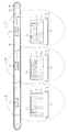
図2は本発明の第2実施例を示す物体搬送装置の模式図である。
この実施例では、第1実施例で示した1セットの搬送単位Aを複数個配置する。つまり、複数個の搬送単位A1 ,A2 ,A3 …を配置するようにしたものである。すなわち、ここでは、長尺の管状のパイプ21内に複数個(例えば、3個)の1次側磁石としての永久磁石21 ,22 ,23 …を配置し、これに対応した2次側磁石としての高温超電導バルク体51 ,52 ,53 …をセットし、複数の物体101 ,102 ,103 …の搬送を可能にしたものである。
【0012】
なお、図2において、61 ,62 ,63 …は液体窒素容器、71 ,72 ,73 …は液体窒素容器内に封入される液体窒素、81 ,82 ,83 …は搬送物体(例えば、半導体ウエハ)101 ,102 ,103 …を載置する容器、91 ,92 ,93 …は容器を吊るす紐である。22は駆動プーリー、23はワイヤである。
このように、第2実施例によれば、所望の個数の搬送装置を容易に構築することができる。
【0013】
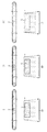
次に、本発明の第3実施例について説明する。
図3は本発明の第3実施例を示す物体搬送装置の模式図であり、第1実施例と同じ部分には同じ番号を付してその説明は省略する。
この実施例では、第1実施例で示した管状のパイプを含む搬送装置を複数個接続して配置する。つまり、搬送装置I、搬送装置II、搬送装置III を直列に配置して、搬送物体10の複数の処理工程に対応した搬送装置群を構築するようにしたものである。
【0014】
このように、第3実施例によれば、複数の処理工程に対応した搬送物体の搬送システムを容易に構築することができる。
次に、本発明の第1参考例について説明する。
図4は本発明の第1参考例を示す物体搬送装置の模式図である。
この図において、31は非磁性体によって作られた管状のパイプ、32はその管状のパイプ内に配置される1次側磁石としての高温超電導バルク体、33は液体窒素容器、34はその液体窒素容器内に封入される液体窒素である。
【0015】
また、35は2次側磁石としての永久磁石、36はその永久磁石に吊るされる容器、37はその容器を吊るすための紐、38はその容器に載置される搬送物体(例えば、半導体ウエハ)であり、これらは、クリーンルーム30内に設けられる。
本参考例では、非磁性体によって作られた管状のパイプ31内には1次側磁石としての高温超電導バルク体32が配置され、この高温超電導バルク体32を含む液体窒素容器33を管状のパイプ31内に流体を流すことによって、液体窒素容器33を移動させるように構成することができる。
【0016】
なお、流体によらず、第1実施例のように、ワイヤを介して、駆動機構によって駆動するようにしてもよい。
一方、管状のパイプ31の外部に、1次側磁石としての高温超電導バルク体32と対向するように、2次側磁石としての永久磁石35を組み合わせるようにして、管状のパイプ31内の1次側磁石としての高温超電導バルク体32を移動させることによって、2次側磁石としての永久磁石35を含む移動物体を管状のパイプ31に沿って追随的に移動させることができる。
【0017】
また、永久磁石35には紐37がかけられ、容器36が釣られており、その容器36内に搬送すべき物体(例えば、半導体ウエハ)38が搭載されて搬送されるようになっている。
このように、1次側磁石としての高温超電導バルク体32と対向するように、2次側磁石としての永久磁石35を組み合わせることにより、磁束のピン止め効果によって、1次側磁石と2次側磁石の間に一定の距離(ギャップ)を確保することができ、2次側磁石と管状のパイプの接触を一切無くして、物体の搬送を行うことができる。
【0018】
このように、第1参考例によれば、特に、物体を搬送する2次側磁石としては永久磁石だけでよく構造が簡単であり、その搬送装置の組立が容易である。
この参考例においても、第2実施例及び第3実施例を容易に適用することができる。
さらに、管状のパイプを気密構造とすれば、ガイドパイプ内の駆動装置、及び1次側磁石とパイプ内壁の間等で発生する塵埃がパイプ外部の空間に混入することもなくなる。つまり、クリーンルーム30内での搬送装置として好適である。
【0019】
次に、本発明の第2参考例について説明する。
図5は本発明の第2参考例を示す物体搬送装置の模式図である。
この参考例においては、可撓性のある材料によるループ状のガイドパイプ41を配置して、そのガイドパイプ41内に1次側磁石42を配置し、その1次側磁石42に対応した2次側磁石43に搬送物体44をセットして、ガス封入口45からガスを封入して、1次側磁石42を駆動するようにしたり、或いは、巻き込みリール47と繰り出しリール48を配置して、複数の1次側磁石42を駆動するようにしてもよい。なお、46はガス排出口である。
【0020】
このように、第2参考例によれば、搬送ルートを自在に構築する事が可能である。
また、このような方式を採用すれば、搬送装置の長尺化、搬送体の数の増大にも容易に対応できる。
次に、本発明の第3参考例について説明する。
【0021】
図6は本発明の第3参考例を示す物体搬送装置の模式図、図7はその物体搬送装置の平面図である。
これらの図において、51は駆動可能な1次側磁石、53は長レーストラックコイル(あるいは2本の導体)であり、1次側磁石51の下方に配置され、直流電流が異なった方向に流れる往復導電路を有する。55はその長レーストラックコイル53に給電するためのDC電源、57は1次側磁石51によって駆動される高温超電導バルク体(2次側磁石)である。なお、Gはギャップである。
【0022】
このように、1次側磁石51の移動に追従して高温超電導バルク体57が電磁力による非接触支持状態で駆動される点は、前記参考例と同様であるが、この参考例によれば、長レーストラックコイル53が磁気レール(詳細は後述)の働きをして、高温超電導バルク体57を支持案内することができる。なお、高温超電導バルク体57には物体搭載装置が設けられるが、ここでは図示していない。
【0023】
次に、本発明の第4参考例について説明する。
図8は本発明の第4参考例を示す物体搬送装置の模式斜視図、図9はその物体搬送装置の模式図、図10はその物体搬送体の浮上原理の説明図、図11はその物体搬送装置の部分平面図である。
これらの図において、61は長レーストラックコイルであり、直流電流が異なった方向に流れる往復導電路を有する。63はその長レーストラックコイル61に直流を給電するためのDC電源、65は着磁した高温超電導バルク体である。
【0024】
また、長レーストラックコイル61の端部にはそのコイル61を上下駆動する装置66(吊り上げ、吊り下げ機構)を配置して、そのコイル61を傾斜させることによって、高温超電導バルク体65を駆動させることができる。なお、この駆動機構としては、前記参考例で示した1次側磁石を設けてこれを移動させるようにしてもよい。又は高温超電導バルク体65に小型プロペラ等の推進駆動機構を備えるようにしてもよい。
【0025】
この参考例においては、図10及び図11に示すように、長レーストラックコイル61の通電電流により、捕捉磁界Hcを有する高温超電導バルク体65に電磁力が働く。この電磁力は高温超電導バルク体65を吊り下げる力、及び軌道に対する案内力として作用する。
高温超電導バルク体65の駆動は、上記した駆動機構により駆動させることができる。
【0026】
例えば、図9に示すように、レーストラックコイル61を高温超電導ビスマス線材で構成し、間隔L1 を150mmとし起磁力を60000ATとした場合、その下にL2 (約100mm)の空隙を開けて高温超電導バルク体(直径46mm、厚み15mmの円板型)65を吊り下げられることが分かった。このときの浮上体の重量は液体窒素容器も含めて約300gとした。うち、バルク体の正味重量が150gである。
【0027】
このように、第4参考例によれば、バルク体の浮上は垂直方向、水平方向、ピッチング方向に対しても安定で、かつ、コイルの長手方向には自由に(摩擦無しで)移動することができる。
また、高温超電導バルク体65には物体搭載装置が設けられるが、ここでは図示していない。
【0028】
次に、本発明の第5参考例について説明する。
図12は本発明の第5参考例を示す物体搬送装置の構成図であり、図12(a)はその物体搬送装置の平面図、図12(b)はその物体搬送装置の全体模式図である。
この参考例では、第4参考例のレーストラックコイルを用いた物体搬送装置を縦続接続して、軌道を延長するようにしたものである。
【0029】
図12において、71は第1のレーストラックコイル、72は第2のレーストラックコイル、73は第3のレーストラックコイル、74は第4のレーストラックコイル、75は第5のレーストラックコイルであり、第1のレーストラックコイル71の終端部71Bと第2のレーストラックコイル72の始端部72A、第2のレーストラックコイル72の終端部72Bと第3のレーストラックコイル73の始端部73A、第3のレーストラックコイル73の終端部73Bと第4のレーストラックコイル74の始端部74A、第4のレーストラックコイル74の終端部74Bと第5のレーストラックコイル75の始端部75A、はそれぞれ軌道をオーバーラップさせた、オーバーラップ区間を配置する。なお、70は着磁した高温超電導バルク体である。
【0030】
また、高温超電導バルク体の駆動機構としては、第4参考例に示したと同様の駆動機構を用いることができる。
そして、各レーストラックコイル71〜75にはそれぞれ各直流電源81〜85が接続される。また、各直流電源81〜85には各スイッチ76〜80が設けられ、各スイッチ76〜80は、制御装置86からの制御信号により、高温超電導バルク体70の移動に対応して開閉される。例えば、直流電源81のスイッチ76がオンとなり、レーストラックコイル71によって搬送されてきた高温超電導バルク体70が第1のレーストラックコイル71の終端部71Bと第2のレーストラックコイル72の始端部72Aとのオーバーラップ区間に至ると、スイッチ76がオフとなり、スイッチ77がオンに切り換わり、第2のレーストラックコイル72により高温超電導バルク体70の支持案内が引きつがれていく。
【0031】
このように、第8実施例によれば、レーストラックコイルを複数個縦続接続して、オーバーラップ区間でレーストラックコイルの電源の切り換えを行うようにしたので、軌道の長尺化を図ることができる。
次に、本発明の第6参考例について説明する。
図13は本発明の第6参考例を示す物体搬送装置の構成図である。
【0032】
この図において、91は支持柱、93は支持柱91を中心としてこの支持柱91の頂部から吊り下げられるとともに、DC電流が異なった方向に流れる往復導電路を有する2重円形コイル、95は支持柱91の頂部から2重円形コイル93を吊るす吊り下げ部材であり、DC電流の給電路も添設される。97はDC電源であり、導電路96と給電路が添設される吊り下げ部材95とを介してDC電流を2重円形コイル93へ直流電流が異なった方向に流れる往復導電路を形成するようにする。また、支持柱91は2重円形コイル93の軸が傾むくように傾斜させることができる。99は2次側磁石(高温超電導バルク体)であり、2重円形コイル93の下部に設けられるとともに、2重円形コイル93の軸の傾きに対応してこの2重円形コイル93に案内されながら駆動される。なお、2次側磁石99には物体搭載装置が設けられるが、ここでは図示していない。
【0033】
このように、第6参考例によれば、2重円形コイル93の軸を傾けることにより、2重円形コイル93の間に吊り下げられた2次側磁石(高温超電導バルク体)99を公転運動させることができる。
なお、本発明は上記実施例に限定されるものではなく、本発明の趣旨に基づいて種々の変形が可能であり、これらを本発明の範囲から排除するものではない。
【0034】
【発明の効果】
以上、詳細に説明したように、本発明によれば、以下のような効果を奏することができる。
(A)永久磁石は搬送体の個数の分だけ必要なだけであり、軌道の距離には関係がなく、かつ、長尺化も極めて容易な物体搬送装置を低コストで構築することができる。
【0035】
(B)所望の個数の搬送装置を容易に構築することができる。
(C)複数の処理工程に対応した搬送物体の搬送システムを構築することができる。
(D)物体を搬送する2次側磁石としては永久磁石だけで構造が簡単であり、その搬送装置の組立が容易である。
【0036】
(E)搬送ルートを自在に構築することができ、搬送装置の長尺化、搬送体の増大にも容易に対応することができる。
(F)長レーストラックコイルによる2次側磁石の案内及び支持(吊り下げ)機能を持たせることができる。
(G)上記(F)の長レーストラックコイルに駆動用の1次側磁石を組み合わせれば弱い力でもバルク体を駆動させることができる。
【0037】
(H)レーストラックコイルを複数個縦続接続して、オーバーラップ区間でレーストラックコイルの電源の切り換えを行うようにしたので、軌道の延長化を図ることができる。
(I)2重円形コイルの軸の傾斜による公転運動を可能にした搬送物体の搬送を行うことができる。
【図面の簡単な説明】
【図1】 本発明の第1実施例を示す物体搬送装置の模式図である。
【図2】 本発明の第2実施例を示す物体搬送装置の模式図である。
【図3】 本発明の第3実施例を示す物体搬送装置の模式図である。
【図4】 本発明の第1参考例を示す物体搬送装置の模式図である。
【図5】 本発明の第2参考例を示す物体搬送装置の模式図である。
【図6】 本発明の第3参考例を示す物体搬送装置の模式図である。
【図7】 本発明の第3参考例を示す物体搬送装置の平面図である。
【図8】 本発明の第4参考例を示す物体搬送装置の模式斜視図である。
【図9】 本発明の第4参考例を示す物体搬送装置の模式図である。
【図10】 本発明の第4参考例を示す物体搬送体の浮上原理の説明図である。
【図11】 本発明の第4参考例を示す物体搬送装置の部分平面図である。
【図12】 本発明の第5参考例を示す物体搬送装置の部分平面図である。
【図13】 本発明の第6参考例を示す物体搬送装置の構成図である。
【符号の説明】
1,31 管状のパイプ(非磁性体)
2,21 ,22 ,23 ,35 永久磁石
3,23 ワイヤ
4,22 駆動プーリー
5,51 ,52 ,53 ,32 高温超電導バルク体
6,61 ,62 ,63 ,33 液体窒素容器
7,71 ,72 ,73 ,34 液体窒素
8,81 ,82 ,83 ,36 容器
9,91 ,92 ,93 ,37 容器を吊るす紐
10,101 ,102 ,103 ,38,44 搬送物体(半導体ウエハ)
21 長尺の管状のパイプ
30 クリーンルーム
41 ループ状のガイドパイプ
42,51 1次側磁石
43,99 2次側磁石
45 ガス封入口
46 ガス排出口
47 巻き込みリール
48 繰り出しリール
53,61 長レーストラックコイル
55,63,97 DC電源
57,65 高温超電導バルク体(2次側磁石)
66 上下駆動する装置
70 着磁した高温超電導バルク体
71 第1のレーストラックコイル
71B 第1のレーストラックコイルの終端部(オーバーラップ区間)
72 第2のレーストラックコイル
72A 第2のレーストラックコイルの始端部(オーバーラップ区間)
72B 第2のレーストラックコイルの終端部(オーバーラップ区間)
73 第3のレーストラックコイル
73A 第3のレーストラックコイルの始端部(オーバーラップ区間)
73B 第3のレーストラックコイルの終端部(オーバーラップ区間)
74 第4のレーストラックコイル
74A 第4のレーストラックコイルの始端部(オーバーラップ区間)
74B 第4のレーストラックコイルの終端部(オーバーラップ区間)
75 第5のレーストラックコイル
75A 第5のレーストラックコイルの始端部(オーバーラップ区間)
76〜80 スイッチ
81〜85 直流電源
86 制御装置
91 支持柱
93 2重円形コイル
95 吊り下げ部材
96 導電路[0001]
BACKGROUND OF THE INVENTION
The present invention relates to an object conveying apparatus that conveys an object without contact.
[0002]
[Prior art]
Conventionally, as a non-contact conveyance device using a high-temperature superconducting bulk body, a device in which a bulk body moving body moves on a track on which permanent magnets are arranged has been proposed.
[0003]
[Problems to be solved by the invention]
However, in the above-described conventional non-contact conveyance device, an expensive permanent magnet is required corresponding to the distance of the track, which is not economical.
Further, in order to make the movement of the carrier smooth, it is necessary to ensure the uniformity of the magnetic field in the longitudinal direction of the track.
[0004]
The present invention eliminates the above-mentioned problems, and the number of permanent magnets is sufficient for the number of transport members, which is not related to the distance of the track, and can be constructed very easily at low cost. An object of the present invention is to provide an object transporting device capable of
[0005]
[Means for Solving the Problems]
In order to achieve the above object, the present invention provides
[1] In the object conveying apparatus, a tubular pipe (1) made of a non-magnetic material, and the wire (3) which is disposed in the tubular pipe (1) and is operable by a driving pulley (4). the primary permanent magnet (2), in the liquid nitrogen container (6) is cooled to below the critical temperature is in the superconducting state with liquid nitrogen, the pinning effect, a constant and the primary permanent magnet (2) distance secondary HTS bulk body that suspended outside the pipe (1) of the tubular What coercive (5) and, the secondary-side high-temperature superconducting bulk body (5) liquid nitrogen container having (6) And a container (8) on which a transport object (10) is placed .
[0006]
DETAILED DESCRIPTION OF THE INVENTION
Hereinafter, embodiments of the present invention will be described in detail with reference to the drawings.
FIG. 1 is a schematic view of an object conveying apparatus showing a first embodiment of the present invention.
In this figure, 1 is a tubular pipe made of a non-magnetic material, 2 is a permanent magnet as a primary magnet, 3 is a wire for moving the
[0007]
Thus, the high-temperature
[0008]
Therefore, a
On the other hand, a primary high-temperature
[0009]
Further, instead of driving the
The
[0010]
Thus, by combining the high-temperature
[0011]
An example of a magnetic levitation device itself having a pinning effect is disclosed in Japanese Patent Application Laid-Open No. 7-213082.
Next, a second embodiment of the present invention will be described.
FIG. 2 is a schematic view of an object conveying apparatus showing a second embodiment of the present invention.
In this embodiment, a plurality of one set of transport units A shown in the first embodiment are arranged. That is, a plurality of transport units A 1 , A 2 , A 3 ... Are arranged. That is, here, a plurality of (for example, three)
[0012]
In FIG. 2, 6 1 , 6 2 , 6 3 ... Are liquid nitrogen containers, 7 1 , 7 2 , 7 3 ... Are liquid nitrogen sealed in the liquid nitrogen containers, 8 1 , 8 2 , 8 3 . Is a container on which transported objects (for example, semiconductor wafers) 10 1 , 10 2 , 10 3 ... Are placed, and 9 1 , 9 2 , 9 3 . 22 is a drive pulley, and 23 is a wire.
As described above, according to the second embodiment, a desired number of transfer devices can be easily constructed.
[0013]
Next, a third embodiment of the present invention will be described.
FIG. 3 is a schematic diagram of an object conveying apparatus according to a third embodiment of the present invention. The same parts as those in the first embodiment are denoted by the same reference numerals, and description thereof is omitted.
In this embodiment, arranging the transport equipment comprising a tubular pipe shown in the first embodiment by connecting a plurality. That is, the transport device I, the transport device II, and the transport device III are arranged in series to construct a transport device group corresponding to a plurality of processing steps of the
[0014]
As described above, according to the third embodiment, it is possible to easily construct a transport system for transported objects corresponding to a plurality of processing steps.
Next, a first reference example of the present invention will be described.
FIG. 4 is a schematic view of an object conveying apparatus showing a first reference example of the present invention.
In this figure, 31 is a tubular pipe made of non-magnetic material, 32 is a high-temperature superconducting bulk body as a primary magnet disposed in the tubular pipe, 33 is a liquid nitrogen container, and 34 is its liquid nitrogen. Liquid nitrogen enclosed in a container.
[0015]
Also, 35 is a permanent magnet as a secondary magnet, 36 is a container suspended by the permanent magnet, 37 is a string for hanging the container, and 38 is a transport object (for example, a semiconductor wafer) placed on the container. These are provided in the
In this reference example, a high-temperature
[0016]
In addition, you may make it drive with a drive mechanism via a wire like 1st Example irrespective of a fluid.
On the other hand, the
[0017]
A
Thus, by combining the
[0018]
Thus, according to the first reference example, in particular, a permanent magnet is sufficient as a secondary side magnet for transporting an object, and the structure is simple, and the assembly of the transport device is easy.
Also in this reference example, the second embodiment and the third embodiment can be easily applied.
Furthermore, if the tubular pipe and airtight structure, drive of the guide pipe, and also eliminates the dust generated by such between the primary-side magnet and the pipe inner wall is mixed in the pipe outside of the space. That is, it is suitable as a transfer device in the
[0019]
Next, a second reference example of the present invention will be described.
FIG. 5 is a schematic view of an object conveying apparatus showing a second reference example of the present invention.
In this reference example, a loop-shaped
[0020]
As described above, according to the second reference example, it is possible to freely construct a transport route.
Further, if such a method is adopted, it is possible to easily cope with an increase in the length of the transport device and an increase in the number of transport bodies.
Next, a third reference example of the present invention will be described.
[0021]
FIG. 6 is a schematic diagram of an object conveying apparatus showing a third reference example of the present invention, and FIG. 7 is a plan view of the object conveying apparatus.
In these figures, 51 is a driveable primary side magnet, 53 is a long race track coil (or two conductors), which is disposed below the
[0022]
Thus, the point that high-temperature
[0023]
Next, a fourth reference example of the present invention will be described.
FIG. 8 is a schematic perspective view of an object conveying apparatus showing a fourth reference example of the present invention, FIG. 9 is a schematic diagram of the object conveying apparatus, FIG. 10 is an explanatory diagram of the principle of levitation of the object conveying body, and FIG. It is a partial top view of a conveying apparatus.
In these drawings,
[0024]
Further, a device 66 (lifting and hanging mechanism) for driving the
[0025]
In this reference example, as shown in FIGS. 10 and 11, an electromagnetic force acts on the high-temperature
The high temperature
[0026]
For example, as shown in FIG. 9, the
[0027]
As described above, according to the fourth reference example, the floating of the bulk body is stable in the vertical direction, the horizontal direction, and the pitching direction, and freely moves (without friction) in the longitudinal direction of the coil. Can do.
The high-temperature
[0028]
Next, a fifth reference example of the present invention will be described.
FIG. 12 is a configuration diagram of an object conveying apparatus showing a fifth reference example of the present invention, FIG. 12 (a) is a plan view of the object conveying apparatus, and FIG. 12 (b) is an overall schematic diagram of the object conveying apparatus. is there.
In this reference example, the object transport device using the racetrack coil of the fourth reference example is connected in cascade to extend the track.
[0029]
In FIG. 12, 71 is a first race track coil, 72 is a second race track coil, 73 is a third race track coil, 74 is a fourth race track coil, and 75 is a fifth race track coil. , beginning 73 of the
[0030]
Further, as the drive mechanism for the high-temperature superconducting bulk body, the same drive mechanism as shown in the fourth reference example can be used.
The
[0031]
Thus, according to the eighth embodiment, a plurality of race track coils are connected in cascade, and the power of the race track coils is switched in the overlap section, so that the track can be lengthened. it can.
Next, a sixth reference example of the present invention will be described.
FIG. 13 is a configuration diagram of an object conveying apparatus showing a sixth reference example of the present invention.
[0032]
In this figure, 91 is a support column, 93 is a double circular coil having a reciprocal conductive path which is suspended from the top of the
[0033]
Thus, according to the sixth reference example, by tilting the axis of the double
In addition, this invention is not limited to the said Example, A various deformation | transformation is possible based on the meaning of this invention, and these are not excluded from the scope of the present invention.
[0034]
【The invention's effect】
As described above in detail, according to the present invention, the following effects can be obtained.
(A) The number of permanent magnets is only as many as the number of transport bodies, and the object transport apparatus which is not related to the distance of the track and which is extremely easy to lengthen can be constructed at low cost.
[0035]
(B) A desired number of transfer devices can be easily constructed.
(C) A conveyance system for a conveyance object corresponding to a plurality of processing steps can be constructed.
(D) The structure of the secondary side magnet for transporting the object is simple with only a permanent magnet, and the assembly of the transport device is easy.
[0036]
(E) A conveyance route can be freely constructed, and it is possible to easily cope with an increase in the length of the conveyance device and an increase in the number of conveyance bodies.
(F) The secondary side magnet can be guided and supported (suspended) by the long racetrack coil.
(G) If a primary magnet for driving is combined with the long racetrack coil of (F) above, the bulk body can be driven even with a weak force.
[0037]
(H) Since a plurality of racetrack coils are connected in cascade and the power supply of the racetrack coils is switched in the overlap section, the track can be extended.
(I) It is possible to transport a transported object that enables a revolving motion by tilting the axis of the double circular coil.
[Brief description of the drawings]
FIG. 1 is a schematic diagram of an object conveying apparatus showing a first embodiment of the present invention.
FIG. 2 is a schematic view of an object conveying apparatus showing a second embodiment of the present invention.
FIG. 3 is a schematic view of an object conveying apparatus showing a third embodiment of the present invention.
FIG. 4 is a schematic diagram of an object conveying apparatus showing a first reference example of the present invention.
FIG. 5 is a schematic diagram of an object conveying apparatus showing a second reference example of the present invention.
FIG. 6 is a schematic diagram of an object conveying apparatus showing a third reference example of the present invention.
FIG. 7 is a plan view of an object conveying apparatus showing a third reference example of the present invention.
FIG. 8 is a schematic perspective view of an object conveying apparatus showing a fourth reference example of the present invention.
FIG. 9 is a schematic diagram of an object conveying apparatus showing a fourth reference example of the present invention.
FIG. 10 is an explanatory diagram of a levitation principle of an object carrier according to a fourth reference example of the present invention.
FIG. 11 is a partial plan view of an object conveying apparatus showing a fourth reference example of the present invention.
FIG. 12 is a partial plan view of an object conveying apparatus showing a fifth reference example of the invention.
FIG. 13 is a configuration diagram of an object conveying apparatus showing a sixth reference example of the present invention.
[Explanation of symbols]
1,31 tubular pipe (non-magnetic material)
2, 2 1 , 2 2 , 2 3 , 35 Permanent magnet 3 , 23
21 Long tubular pipe
30
66
72 Second
72B End of second race track coil (overlap section)
73 Third
73B End of third race track coil (overlap section)
74 Fourth
74B Terminal portion of the fourth race track coil (overlap section)
75 Fifth
76 to 80
Claims (1)
(b)該管状のパイプ内に配置され、駆動プーリーにより動作可能なワイヤに固定される1次側永久磁石と、
(c)液体窒素容器内の液体窒素により臨界温度以下に冷却して超電導状態にされ、ピン止め効果によって、前記1次側永久磁石と一定の距離を保って前記管状のパイプの外部に吊り下げられる2次側高温超電導バルク体と、
(d)該2次側高温超電導バルク体を有する液体窒素容器に掛けられた紐により吊り下げられ搬送物体が載置される容器とを具備することを特徴とする物体搬送装置。 (A) a tubular pipe made of a non-magnetic material;
(B) disposed within the tubular pipe, a primary permanent magnet is fixed to the operable wire by a drive pulley,
The liquid nitrogen in (c) a liquid nitrogen container is in the superconducting state by cooling below the critical temperature, the pinning effect, hanging a certain distance between the primary-side permanent magnet to the outside of the tubular pipe I coercive and the secondary side high-temperature superconducting bulk that lowered,
(D) An object conveying apparatus comprising: a container that is suspended by a string hung on a liquid nitrogen container having the secondary high-temperature superconducting bulk body and on which a conveyed object is placed .
Priority Applications (1)
| Application Number | Priority Date | Filing Date | Title |
|---|---|---|---|
| JP09829599A JP4671374B2 (en) | 1999-04-06 | 1999-04-06 | Object transfer device |
Applications Claiming Priority (1)
| Application Number | Priority Date | Filing Date | Title |
|---|---|---|---|
| JP09829599A JP4671374B2 (en) | 1999-04-06 | 1999-04-06 | Object transfer device |
Publications (2)
| Publication Number | Publication Date |
|---|---|
| JP2000289834A JP2000289834A (en) | 2000-10-17 |
| JP4671374B2 true JP4671374B2 (en) | 2011-04-13 |
Family
ID=14215940
Family Applications (1)
| Application Number | Title | Priority Date | Filing Date |
|---|---|---|---|
| JP09829599A Expired - Fee Related JP4671374B2 (en) | 1999-04-06 | 1999-04-06 | Object transfer device |
Country Status (1)
| Country | Link |
|---|---|
| JP (1) | JP4671374B2 (en) |
Families Citing this family (7)
| Publication number | Priority date | Publication date | Assignee | Title |
|---|---|---|---|---|
| WO2018049104A1 (en) | 2016-09-09 | 2018-03-15 | The Procter & Gamble Company | System and method for simultaneously filling containers of different shapes and/or sizes |
| EP3509979B1 (en) | 2016-09-09 | 2023-06-14 | The Procter & Gamble Company | System and method for independently routing vehicles and delivering containers and closures to unit operation stations |
| WO2018049122A1 (en) | 2016-09-09 | 2018-03-15 | The Procter & Gamble Company | Systems and methods for producing customized products intermixed with mass produced products |
| EP3510457A1 (en) | 2016-09-09 | 2019-07-17 | The Procter and Gamble Company | Methods for simultaneously producing different products on a single production line |
| CA3035963C (en) | 2016-09-09 | 2023-10-24 | The Procter & Gamble Company | System and method for producing products based upon demand |
| EP3509954B1 (en) | 2016-09-09 | 2021-10-20 | The Procter & Gamble Company | System and method for simultaneously filling containers with different fluent compositions |
| EP3510459A2 (en) | 2016-09-09 | 2019-07-17 | The Procter and Gamble Company | System and method for independently routing container-loaded vehicles to create different finished products |
-
1999
- 1999-04-06 JP JP09829599A patent/JP4671374B2/en not_active Expired - Fee Related
Also Published As
| Publication number | Publication date |
|---|---|
| JP2000289834A (en) | 2000-10-17 |
Similar Documents
| Publication | Publication Date | Title |
|---|---|---|
| TWI272665B (en) | Universal modular wafer transport system | |
| JP2656659B2 (en) | Article transfer equipment using high-temperature superconductor | |
| US4766993A (en) | Conveying apparatus | |
| US5631617A (en) | System for levitating and guiding object by electromagnetic attractive force | |
| JP4671374B2 (en) | Object transfer device | |
| JPS62225109A (en) | Conveyor of levitation type | |
| JP3215608B2 (en) | Linear motor type capsule transfer device | |
| JP2547403B2 (en) | Magnetic levitation transport device for vacuum equipment | |
| JP3084132B2 (en) | Magnetic levitation device | |
| JPH0564314A (en) | Drive control method for linear capsule in linear capsule traveling unit | |
| JPH05122807A (en) | Conveyor | |
| JP3799193B2 (en) | Wafer transfer device | |
| JP3185270B2 (en) | Magnetic levitation device | |
| JP3259284B2 (en) | Magnetic levitation transfer device and its branching mechanism | |
| JPH06156729A (en) | Magnetic levitation conveying device | |
| JPH03112301A (en) | Conduit branching system for linear traveling capsule | |
| JP2973380B2 (en) | Magnetic levitation transfer device | |
| JP2711359B2 (en) | Magnetic levitation device | |
| JPS619104A (en) | Magnetic levitating conveyor | |
| JPH04117111A (en) | Magnetic levitation conveyor | |
| JPH11122717A (en) | Linear-mode capsule running equipment | |
| JPS63174895A (en) | Magnetic levitation type carrying manipulator | |
| JPH05336614A (en) | Superconducting magnetic bearing carrier | |
| JP3220287B2 (en) | Magnetic levitation transfer device | |
| JPH04308124A (en) | Substrate conveying device and orthogonal conveyance chamber module using it |
Legal Events
| Date | Code | Title | Description |
|---|---|---|---|
| A621 | Written request for application examination |
Free format text: JAPANESE INTERMEDIATE CODE: A621 Effective date: 20050627 |
|
| A977 | Report on retrieval |
Free format text: JAPANESE INTERMEDIATE CODE: A971007 Effective date: 20080814 |
|
| A131 | Notification of reasons for refusal |
Free format text: JAPANESE INTERMEDIATE CODE: A131 Effective date: 20080902 |
|
| A521 | Written amendment |
Free format text: JAPANESE INTERMEDIATE CODE: A523 Effective date: 20081014 |
|
| A02 | Decision of refusal |
Free format text: JAPANESE INTERMEDIATE CODE: A02 Effective date: 20090127 |
|
| A521 | Written amendment |
Free format text: JAPANESE INTERMEDIATE CODE: A523 Effective date: 20090210 |
|
| A911 | Transfer of reconsideration by examiner before appeal (zenchi) |
Free format text: JAPANESE INTERMEDIATE CODE: A911 Effective date: 20090318 |
|
| A912 | Removal of reconsideration by examiner before appeal (zenchi) |
Free format text: JAPANESE INTERMEDIATE CODE: A912 Effective date: 20090522 |
|
| A521 | Written amendment |
Free format text: JAPANESE INTERMEDIATE CODE: A523 Effective date: 20101018 |
|
| A01 | Written decision to grant a patent or to grant a registration (utility model) |
Free format text: JAPANESE INTERMEDIATE CODE: A01 |
|
| A61 | First payment of annual fees (during grant procedure) |
Free format text: JAPANESE INTERMEDIATE CODE: A61 Effective date: 20110117 |
|
| R150 | Certificate of patent or registration of utility model |
Free format text: JAPANESE INTERMEDIATE CODE: R150 |
|
| FPAY | Renewal fee payment (event date is renewal date of database) |
Free format text: PAYMENT UNTIL: 20140128 Year of fee payment: 3 |
|
| FPAY | Renewal fee payment (event date is renewal date of database) |
Free format text: PAYMENT UNTIL: 20140128 Year of fee payment: 3 |
|
| S533 | Written request for registration of change of name |
Free format text: JAPANESE INTERMEDIATE CODE: R313533 |
|
| FPAY | Renewal fee payment (event date is renewal date of database) |
Free format text: PAYMENT UNTIL: 20140128 Year of fee payment: 3 |
|
| R350 | Written notification of registration of transfer |
Free format text: JAPANESE INTERMEDIATE CODE: R350 |
|
| LAPS | Cancellation because of no payment of annual fees |