DE102012210329A1 - feeding apparatus - Google Patents
feeding apparatus Download PDFInfo
- Publication number
- DE102012210329A1 DE102012210329A1 DE102012210329A DE102012210329A DE102012210329A1 DE 102012210329 A1 DE102012210329 A1 DE 102012210329A1 DE 102012210329 A DE102012210329 A DE 102012210329A DE 102012210329 A DE102012210329 A DE 102012210329A DE 102012210329 A1 DE102012210329 A1 DE 102012210329A1
- Authority
- DE
- Germany
- Prior art keywords
- product
- holder
- conveying
- products
- stacks
- Prior art date
- Legal status (The legal status is an assumption and is not a legal conclusion. Google has not performed a legal analysis and makes no representation as to the accuracy of the status listed.)
- Withdrawn
Links
Images
Classifications
-
- B—PERFORMING OPERATIONS; TRANSPORTING
- B65—CONVEYING; PACKING; STORING; HANDLING THIN OR FILAMENTARY MATERIAL
- B65B—MACHINES, APPARATUS OR DEVICES FOR, OR METHODS OF, PACKAGING ARTICLES OR MATERIALS; UNPACKING
- B65B35/00—Supplying, feeding, arranging or orientating articles to be packaged
- B65B35/30—Arranging and feeding articles in groups
- B65B35/44—Arranging and feeding articles in groups by endless belts or chains
-
- B—PERFORMING OPERATIONS; TRANSPORTING
- B65—CONVEYING; PACKING; STORING; HANDLING THIN OR FILAMENTARY MATERIAL
- B65B—MACHINES, APPARATUS OR DEVICES FOR, OR METHODS OF, PACKAGING ARTICLES OR MATERIALS; UNPACKING
- B65B35/00—Supplying, feeding, arranging or orientating articles to be packaged
- B65B35/10—Feeding, e.g. conveying, single articles
- B65B35/24—Feeding, e.g. conveying, single articles by endless belts or chains
-
- B—PERFORMING OPERATIONS; TRANSPORTING
- B65—CONVEYING; PACKING; STORING; HANDLING THIN OR FILAMENTARY MATERIAL
- B65B—MACHINES, APPARATUS OR DEVICES FOR, OR METHODS OF, PACKAGING ARTICLES OR MATERIALS; UNPACKING
- B65B35/00—Supplying, feeding, arranging or orientating articles to be packaged
- B65B35/30—Arranging and feeding articles in groups
- B65B35/50—Stacking one article, or group of articles, upon another before packaging
-
- B—PERFORMING OPERATIONS; TRANSPORTING
- B65—CONVEYING; PACKING; STORING; HANDLING THIN OR FILAMENTARY MATERIAL
- B65B—MACHINES, APPARATUS OR DEVICES FOR, OR METHODS OF, PACKAGING ARTICLES OR MATERIALS; UNPACKING
- B65B57/00—Automatic control, checking, warning, or safety devices
- B65B57/10—Automatic control, checking, warning, or safety devices responsive to absence, presence, abnormal feed, or misplacement of articles or materials to be packaged
- B65B57/16—Automatic control, checking, warning, or safety devices responsive to absence, presence, abnormal feed, or misplacement of articles or materials to be packaged and operating to stop, or to control the speed of, the machine as a whole
-
- B—PERFORMING OPERATIONS; TRANSPORTING
- B65—CONVEYING; PACKING; STORING; HANDLING THIN OR FILAMENTARY MATERIAL
- B65G—TRANSPORT OR STORAGE DEVICES, e.g. CONVEYORS FOR LOADING OR TIPPING, SHOP CONVEYOR SYSTEMS OR PNEUMATIC TUBE CONVEYORS
- B65G47/00—Article or material-handling devices associated with conveyors; Methods employing such devices
- B65G47/02—Devices for feeding articles or materials to conveyors
- B65G47/04—Devices for feeding articles or materials to conveyors for feeding articles
- B65G47/06—Devices for feeding articles or materials to conveyors for feeding articles from a single group of articles arranged in orderly pattern, e.g. workpieces in magazines
- B65G47/08—Devices for feeding articles or materials to conveyors for feeding articles from a single group of articles arranged in orderly pattern, e.g. workpieces in magazines spacing or grouping the articles during feeding
- B65G47/082—Devices for feeding articles or materials to conveyors for feeding articles from a single group of articles arranged in orderly pattern, e.g. workpieces in magazines spacing or grouping the articles during feeding grouping articles in rows
-
- B—PERFORMING OPERATIONS; TRANSPORTING
- B65—CONVEYING; PACKING; STORING; HANDLING THIN OR FILAMENTARY MATERIAL
- B65G—TRANSPORT OR STORAGE DEVICES, e.g. CONVEYORS FOR LOADING OR TIPPING, SHOP CONVEYOR SYSTEMS OR PNEUMATIC TUBE CONVEYORS
- B65G47/00—Article or material-handling devices associated with conveyors; Methods employing such devices
- B65G47/22—Devices influencing the relative position or the attitude of articles during transit by conveyors
- B65G47/26—Devices influencing the relative position or the attitude of articles during transit by conveyors arranging the articles, e.g. varying spacing between individual articles
- B65G47/28—Devices influencing the relative position or the attitude of articles during transit by conveyors arranging the articles, e.g. varying spacing between individual articles during transit by a single conveyor
-
- B—PERFORMING OPERATIONS; TRANSPORTING
- B65—CONVEYING; PACKING; STORING; HANDLING THIN OR FILAMENTARY MATERIAL
- B65G—TRANSPORT OR STORAGE DEVICES, e.g. CONVEYORS FOR LOADING OR TIPPING, SHOP CONVEYOR SYSTEMS OR PNEUMATIC TUBE CONVEYORS
- B65G47/00—Article or material-handling devices associated with conveyors; Methods employing such devices
- B65G47/22—Devices influencing the relative position or the attitude of articles during transit by conveyors
- B65G47/26—Devices influencing the relative position or the attitude of articles during transit by conveyors arranging the articles, e.g. varying spacing between individual articles
- B65G47/30—Devices influencing the relative position or the attitude of articles during transit by conveyors arranging the articles, e.g. varying spacing between individual articles during transit by a series of conveyors
-
- B—PERFORMING OPERATIONS; TRANSPORTING
- B65—CONVEYING; PACKING; STORING; HANDLING THIN OR FILAMENTARY MATERIAL
- B65G—TRANSPORT OR STORAGE DEVICES, e.g. CONVEYORS FOR LOADING OR TIPPING, SHOP CONVEYOR SYSTEMS OR PNEUMATIC TUBE CONVEYORS
- B65G54/00—Non-mechanical conveyors not otherwise provided for
- B65G54/02—Non-mechanical conveyors not otherwise provided for electrostatic, electric, or magnetic
-
- B—PERFORMING OPERATIONS; TRANSPORTING
- B65—CONVEYING; PACKING; STORING; HANDLING THIN OR FILAMENTARY MATERIAL
- B65B—MACHINES, APPARATUS OR DEVICES FOR, OR METHODS OF, PACKAGING ARTICLES OR MATERIALS; UNPACKING
- B65B9/00—Enclosing successive articles, or quantities of material, e.g. liquids or semiliquids, in flat, folded, or tubular webs of flexible sheet material; Subdividing filled flexible tubes to form packages
- B65B9/06—Enclosing successive articles, or quantities of material, in a longitudinally-folded web, or in a web folded into a tube about the articles or quantities of material placed upon it
Abstract
Die Erfindung geht aus von einer Zufuhrvorrichtung zum Zuführen von Produkten (12a–k) und/oder Produktstapeln (14a–k) zu einem Verpackungsprozess einer Verpackungsmaschine (16a, 16d–k), insbesondere einer horizontalen Schlauchpackmaschine, mit zumindest einer als geschlossene Schleife (18a, 18c–k) ausgebildeten Führungseinheit (20a–k), auf welcher eine Vielzahl angeordneter Förderelemente (22a–k) zumindest entlang zumindest eines Arbeitsabschnitts (24a, 24c–d, 24f–k) der Führungseinheit (20a–d, 20f–k) voneinander unabhängig geschwindigkeits- und/oder positionsgeregelt antreibbar angeordnet sind. Es wird vorgeschlagen, dass zumindest ein Förderelement (22a–k) einen Halter (26a–k) und zumindest ein entgegen einer Förderrichtung (28a, 28c–k) folgendes Förderelement (22a–k) einen Gegenhalter (30a–k) aufweistThe invention is based on a supply device for feeding products (12a-k) and / or product stacks (14a-k) to a packaging process of a packaging machine (16a, 16d-k), in particular a horizontal tubular packaging machine, with at least one closed loop (FIG. 18a, 18c-k), on which a plurality of arranged conveying elements (22a-k) at least along at least one working portion (24a, 24c-d, 24f-k) of the guide unit (20a-d, 20f-c). k) are arranged independently of each other in terms of speed and / or position-controlled drivable. It is proposed that at least one conveying element (22a-k) has a holder (26a-k) and at least one conveying element (22a-k) following a conveying direction (28a, 28c-k) has a counter-holder (30a-k)
Description
Stand der TechnikState of the art
Es sind aus der
Offenbarung der ErfindungDisclosure of the invention
Die Erfindung geht aus von einer Zufuhrvorrichtung zum Zuführen von Produkten und/oder Produktstapeln zu einem Verpackungsprozess einer Verpackungsmaschine, insbesondere einer horizontalen Schlauchpackmaschine, mit zumindest einer als geschlossene Schleife ausgebildeten Führungseinheit, auf welcher eine Vielzahl angeordneter Förderelemente zumindest entlang zumindest eines Arbeitsabschnitts der Führungseinheit voneinander unabhängig geschwindigkeits- und/oder positionsgeregelt antreibbar angeordnet sind.The invention relates to a feeding device for feeding products and / or product stacks to a packaging process of a packaging machine, in particular a horizontal tubular packaging machine, with at least one closed loop guide unit on which a plurality of arranged conveying elements independent of each other at least along at least one working portion of the guide unit are arranged drivable driven speed and / or position.
Es wird vorgeschlagen, dass zumindest ein Förderelement einen Halter und zumindest ein entgegen einer Förderrichtung folgendes Förderelement einen Gegenhalter aufweist. Ein Gegenhalter kann an einem einen Halter aufweisenden Förderelement in Förderrichtung folgenden Förderelement angeordnet sein, bevorzugt am nächsten in Förderrichtung folgenden Förderelement. Unter einer „Förderrichtung“ soll in diesem Zusammenhang insbesondere diejenige Richtung entlang der Führungseinheit verstanden werden, in der sich die Förderelemente beim Zuführen von Produkten im Umlauf befinden. Die Zufuhrvorrichtung kann insbesondere dazu vorgesehen sein, Produkte und/oder Produktstapel in einem vordefinierten Abstand und mit einer an den Verpackungsprozess angepassten Geschwindigkeit synchronisiert in den Verpackungsprozess einzubringen. Unter einem „Produkt“ soll in diesem Zusammenhang ein zu verpackender Gegenstand oder eine Packung, die zumindest einen Gegenstand enthält, verstanden werden. Eine Packung kann in diesem Zusammenhang insbesondere eine Folienverpackung, wie ein Schlauchbeutel, oder ein Tray sein. Ein Gegenstand kann insbesondere ein stückiges Nahrungsmittel, bevorzugt ein Biskuit, insbesondere scheibenförmiges Biskuit, sein. Die Zufuhrvorrichtung kann bevorzugt dazu vorgesehen sein, Gegenstände und/oder Trays und/oder Folienpackungen, die Gegenstände enthalten, und/oder Stapel von Gegenständen und/oder Trays und/oder Folienpackungen in den Verpackungsprozess einzubringen. Unter einem „Produktstapel“ soll in diesem Zusammenhang insbesondere ein vertikaler oder bevorzugt horizontaler Stapel, der von mehreren Produkten, wie Gegenständen und/oder Packungen, gebildet wird, verstanden werden. Es ist weiter möglich, dass ein Produktstapel mehrere Stapel von Produkten enthält, insbesondere kann ein horizontaler Produktstapel von mehreren vertikalen Stapeln von Produkten gebildet sein. Unter einer „horizontalen Schlauchbeutelmaschine“ soll in diesem Zusammenhang insbesondere eine, dem Fachmann als HFFS „Horizontal Form Fill Seal“-Verpackungsmaschine bekannte Verpackungsmaschine verstanden werden, die dazu vorgesehen ist, aus einer Materialbahn zumindest einen Folienschlauch um einen oder mehrere zu verpackende Produkte zu einem Schlauchbeutel zu formen und diesen an beiden Enden zu verschließen. Bevorzugt kann die horizontale Schlauchbeutelmaschine dazu vorgesehen sein, zumindest 100 Schlauchbeutel/Minute zu erstellen, besonders bevorzugt mehr als 250 Schlauchbeutel/Minute. Bevorzugt kann die Schlauchbeutelmaschine dazu vorgesehen sein, bis zu 1000, besonders bevorzugt bis zu 1500 Schlauchbeutel/Minute zu erstellen. Zu verpackende Produkte und der um die Produkte geformte Folienschlauch werden während des Formens des Schlauchs, dem Einbringen der zu verpackenden Produkte in den Folienschlauch und dem Verschließen des Schlauchs bevorzugt zumindest im Wesentlichen in einer horizontalen Verpackungsrichtung bewegt. Unter „zumindest im Wesentlichen horizontal“ soll in diesem Zusammenhang insbesondere eine Richtung verstanden werden, die weniger als 60°, bevorzugt weniger als 45°, besonders bevorzugt um weniger als 20° von einer senkrecht zu einer Gewichtskraft angeordneten Horizontalen abweicht. Unter einem „Förderelement“ soll in diesem Zusammenhang insbesondere ein von Lagermitteln der Führungseinheit beweglich gelagertes Element verstanden werden, das dazu vorgesehen ist, in zumindest einem Betriebszustand ein durch die Zufuhrvorrichtung zugeführtes Produkt und/oder einen Produktstapel in zumindest einer Richtung abzustützen, insbesondere durch einen Halter und/oder Gegenhalter. Unter einer „geschlossenen Schleife“ soll in diesem Zusammenhang insbesondere eine Bahn verstanden werden, in der sich die Förderelemente in einem Umlauf befinden. Die Bahn kann eine beliebige Form aufweisen. Bevorzugt ist die Bahn zumindest im Bereich einer Zufuhrstrecke und/oder einer Rückfuhrstrecke zumindest im Wesentlichen als Gerade ausgebildet. Unter „zumindest im Wesentlichen“ soll in diesem Zusammenhang eine seitliche Bahnabweichung von weniger als 5%, besonders bevorzugt weniger als 1% bezogen auf eine Bahnlänge in Bahnrichtung verstanden werden. Bevorzugt weist die Bahn zwischen Zufuhrstrecke und Rückfuhrstrecke bevorzugt kreisförmige Umlenkbereiche auf. Die Führungseinheit kann besonders kompakt und kostengünstig sein. Insbesondere kann die Zufuhrstrecke zumindest im Wesentlichen parallel zur Verpackungsrichtung des Verpackungsprozesses der Verpackungsmaschine angeordnet sein. Die Führungseinheit kann besonders gut geeignet sein, der Verpackungsmaschine Produkte in Verpackungsrichtung zuzuführen. In einer weiteren Ausbildung kann die Zufuhrstrecke in einem rechten Winkel zur Verpackungsrichtung angeordnet sein. Produkte und/oder Produktstapel können quer besonders platzsparend in den Verpackungsprozess eingebracht werden. Der Fachmann wird weitere, sinnvolle Anordnungen der Zufuhrstrecke festlegen. Die Bahn kann Mittel enthalten, um weitere Förderelemente in den Umlauf zu bringen oder diese aus dem Umlauf zu entfernen, wie insbesondere Weichen. Eine Gesamtzahl von Förderelementen kann vorteilhaft angepasst werden. It is proposed that at least one conveying element has a holder and at least one conveying element following a conveying direction has a counter holder. A counter-holder may be arranged on a conveyor element having a holder in the conveying direction following a conveying element, preferably on the next conveying element following in the conveying direction. In this context, a "conveying direction" should be understood as meaning, in particular, that direction along the guide unit in which the conveying elements are in circulation when feeding products. The supply device can be provided, in particular, for introducing products and / or product stacks synchronized into the packaging process at a predefined distance and at a speed adapted to the packaging process. In this context, a "product" is to be understood as meaning an article to be packaged or a pack containing at least one article. In this context, a pack may in particular be a foil packaging, such as a tubular bag, or a tray. An article may in particular be a lumpy foodstuff, preferably a biscuit, in particular disc-shaped biscuit. The feeding device can preferably be provided for introducing objects and / or trays and / or foil packs containing articles and / or stacks of articles and / or trays and / or foil packs into the packaging process. In this context, a "product stack" is to be understood as meaning, in particular, a vertical or preferably horizontal stack formed by a plurality of products, such as articles and / or packs. It is also possible that a product stack contains several stacks of products, in particular a horizontal product stack can be formed by a plurality of vertical stacks of products. In this context, a "horizontal tubular bag machine" is to be understood as meaning, in particular, a packaging machine known to the person skilled in the art as a HFFS "Horizontal Form Fill Seal" packaging machine, which is intended to make at least one film tube from one material web around one or more products to be packed Form tubular bag and close it at both ends. Preferably, the horizontal tubular bag machine can be provided to create at least 100 tubular bags / minute, more preferably more than 250 tubular bags / minute. Preferably, the tubular bag machine can be provided to create up to 1000, more preferably up to 1500 tubular bags / minute. Products to be packaged and the film tube formed around the products are preferably moved at least substantially in a horizontal direction of packaging during molding of the tube, placing the products to be packaged in the foil tube, and sealing the tube. By "at least substantially horizontal" is meant in this context in particular a direction which deviates less than 60 °, preferably less than 45 °, more preferably by less than 20 ° from a horizontal arranged perpendicular to a weight force. In this context, a "conveying element" should be understood as meaning, in particular, an element movably supported by bearing means of the guide unit, which is intended to support, in at least one operating state, a product supplied by the feeding device and / or a product stack in at least one direction, in particular by one Holder and / or counterholder. A "closed loop" is to be understood in this context in particular a web in which the conveying elements are in one circulation. The web can have any shape. Preferably, the web is at least substantially in the form of a straight line, at least in the region of a feed path and / or a return path. By "at least substantially" should in this context a lateral path deviation of less than 5%, especially preferably be understood less than 1% based on a web length in the web direction. The web preferably has circular deflection regions between the feed path and the return path. The guide unit can be particularly compact and inexpensive. In particular, the feed path can be arranged at least substantially parallel to the packaging direction of the packaging process of the packaging machine. The guide unit may be particularly well suited to supply products to the packaging machine in the packaging direction. In a further embodiment, the supply path can be arranged at a right angle to the packaging direction. Products and / or product stacks can be incorporated into the packaging process in a particularly space-saving manner. The person skilled in the art will specify further, sensible arrangements of the supply route. The web may include means for circulating or removing further conveying elements, such as, in particular, turnouts. A total number of conveying elements can be advantageously adapted.
Bevorzugt kann die Zufuhrvorrichtung an der Verpackungsmaschine höhenverstellbar angeordnet sein. Unterschiedliche Produkthöhen können ausgeglichen werden. Unter einer „Höhe“ soll in diesem Zusammenhang insbesondere eine Richtung zumindest im Wesentlichen parallel zur Gewichtskraft verstanden werden. Unter einer „Zufuhrstrecke“ soll in diesem Zusammenhang insbesondere der Teil der Führungseinheit verstanden werden, der sich von einem Produktübernahmebereich bis zu einem Produktabgabebereich erstreckt. Unter einem „Produktübernahmebereich“ soll in diesem Zusammenhang insbesondere ein Bereich der Führungseinheit verstanden werden, in dem die Zufuhrvorrichtung mit Produkten und/oder Produktstapeln beladen wird. Unter einem Produktabgabebereich soll in diesem Zusammenhang insbesondere ein Bereich der Führungseinheit verstanden werden, in dem die Zufuhrvorrichtung die Produkte an den Verpackungsprozess abgibt. Unter einem „Arbeitsabschnitt“ soll in diesem Zusammenhang insbesondere ein Abschnitt der Zufuhrstrecke verstanden werden, in dem die Förderelemente unabhängig geschwindigkeits- und/oder positionsgeregelt antreibbar sind. Unter „unabhängig“ antreibbar soll in diesem Zusammenhang insbesondere verstanden werden, dass Geschwindigkeits- und/oder Positionssollwerte der Förderelemente innerhalb von Grenzen unabhängig eingestellt werden können, in denen die Förderelemente kollisionsfrei sind. Insbesondere kann der Produktübernahmebereich und/oder der Produktabgabereich ein Arbeitsabschnitt oder Teil eines Arbeitsabschnitts sein. Förderelemente können außerhalb der Arbeitsabschnitte bevorzugt passiv oder geschwindigkeits- und/oder positionsgesteuert antreibbar sein. Unter einem „Halter“ soll in diesem Zusammenhang insbesondere ein Element verstanden werden, das dazu vorgesehen ist, in zumindest einem Betriebszustand ein Produkt oder einen Produktstapel in der Förderrichtung abzustützen. Unter einem „Gegenhalter“ soll in diesem Zusammenhang insbesondere ein Element verstanden werden, das dazu vorgesehen ist, in zumindest einem Betriebszustand ein Produkt oder einen Produktstapel entgegen der Förderrichtung abzustützen. Der Gegenhalter kann insbesondere dazu vorgesehen sein, zu verhindern, dass die Produkte und/oder die Produktstapel in Förderrichtung kippen. Die Förderelemente können zusätzlich Produktauflagen aufweisen, um Produkte oder Produktstapel gegen die Gewichtskraft abzustützen. Bevorzugt kann die Zufuhrvorrichtung eine Auflagefläche aufweisen, die die Produkte abstützt. Die Führungseinheit und die Förderelemente sind bevorzugt auf einer produktabgewandten Seite der Auflagefläche angeordnet. Die Auflagefläche weist bevorzugt zumindest eine sich in Förderrichtung erstreckende Ausnehmung auf, durch die die Halter und Gegenhalter auf die produktzugewandte Seite der Auflagefläche ragen. Halter und Gegenhalter eines Produkts oder einer Produktgruppe können in und entgegen der Förderrichtung unabhängig bewegt werden. Bei einer Produktübernahme kann der Halter und Gegenhalter angepasst an einen Produktübernahmeprozess bewegt werden. Insbesondere kann bei einer Übernahme mehrerer Produkte ein Abstand zwischen Halter und Gegenhalter an eine wachsende Produktzahl angepasst vergrößert werden. Abstand von Halter und Gegenhalter kann einer Produkt- oder Produktstapellänge angepasst werden. Produkte oder Produktstapel können in den Produktübernahmebereichen und/oder den Produktabgabebereichen unabhängig synchronisiert übernommen und/oder abgegeben werden. Eine Geschwindigkeit bei der Produktüberahme und/oder Produktabgabe kann besonders hoch sein. Die Geschwindigkeit kann besonders gut auf den vorhergehenden oder den nachfolgenden Prozess abgestimmt sein, insbesondere auf die Verpackungsgeschwindigkeit und/oder eine Foliengeschwindigkeit der Verpackungsmaschine. Unter „Teilung“ soll ein Abstand zwischen aufeinander folgenden Haltern verstanden werden. Die Teilung aufeinander folgender Halter kann unabhängig eingestellt werden. Eine Vorlaufstrecke, in der Packungsabstände zwischen Produkten oder Produktstapeln vor der Produktübernahme eingestellt werden, kann entfallen. Die Zufuhrvorrichtung kann Produkte mit unterschiedlichen Produktlängen und/oder Produktstapellängen und/oder Packungsabständen formatwechselfrei zuführen. Unter einem „Formatwechsel“ soll in diesem Zusammenhang insbesondere eine Umstellung verstanden werden, bei der Teile ausgetauscht und/oder durch einen insbesondere manuellen Eingriff angepasst werden, wie insbesondere eingestellt und/oder justiert. Die Zufuhrvorrichtung kann besonders effizient und flexibel sein. Eine Baulänge der Zufuhrvorrichtung kann besonders kurz sein. Eine Leistungsfähigkeit der Zufuhrvorrichtung kann besonders hoch sein. Preferably, the supply device can be arranged to be height-adjustable on the packaging machine. Different product heights can be compensated. In this context, a "height" is to be understood as meaning, in particular, a direction at least substantially parallel to the weight force. In this context, a "supply line" is to be understood as meaning, in particular, the part of the guide unit which extends from a product transfer area to a product delivery area. In this context, a "product transfer area" is to be understood as meaning, in particular, a region of the guide unit in which the delivery device is loaded with products and / or product stacks. In this context, a product dispensing area should be understood as meaning, in particular, a region of the guidance unit in which the dispensing device delivers the products to the packaging process. In this context, a "working section" is to be understood as meaning, in particular, a section of the supply route in which the conveying elements can be driven independently of speed and / or position-controlled. In this context, the term "independently drivable" should be understood in particular to mean that speed and / or position setpoint values of the conveyor elements can be set independently within limits in which the conveyor elements are free of collision. In particular, the product transfer area and / or the product delivery area may be a work section or part of a work section. Conveying elements can be driven outside of the working sections preferably passive or speed and / or position controlled. In this context, a "holder" is to be understood as meaning, in particular, an element which is intended to support a product or a product stack in the conveying direction in at least one operating state. In this context, a "counterholder" is to be understood as meaning, in particular, an element which is intended to support a product or a product stack in at least one operating state counter to the conveying direction. The counter holder can be provided, in particular, to prevent the products and / or the product stacks from tilting in the conveying direction. The conveying elements may additionally have product pads to support products or product stacks against the weight. Preferably, the supply device may have a bearing surface which supports the products. The guide unit and the conveying elements are preferably arranged on a product side facing away from the support surface. The bearing surface preferably has at least one recess extending in the conveying direction, through which the holder and counter-holder protrude onto the product-facing side of the bearing surface. Holder and counterholder of a product or a product group can be moved independently in and against the conveying direction. During a product takeover, the holder and counterholder can be moved in accordance with a product takeover process. In particular, in the case of a takeover of several products, a distance between holder and counterholder can be increased to a growing number of products. Distance between holder and counterholder can be adjusted to a product or product stack length. Products or product stacks can be independently synchronized and / or delivered in the product transfer areas and / or the product delivery areas. A speed of product takeover and / or product delivery can be particularly high. The speed can be particularly well matched to the preceding or the subsequent process, in particular to the packaging speed and / or a film speed of the packaging machine. By "division" is meant a distance between successive holders. The pitch of successive holders can be adjusted independently. A delay line, in which packing intervals between products or product stacks are set before the product is taken over, can be dispensed with. The delivery device may deliver products with different product lengths and / or product stack lengths and / or packing distances format change free. A "format change" is to be understood in this context, in particular, a change in the parts replaced and / or adapted by a particular manual intervention, such as in particular adjusted and / or adjusted. The delivery device can be particularly efficient and flexible. An overall length of the feed device can be particularly short. A performance of the delivery device can be particularly high.
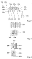
Weiter wird vorgeschlagen, dass zumindest ein Förderelement zumindest einen Halter und zumindest einen Gegenhalter aufweist. Ein Förderelement kann gleichzeitig einen Halter für ein Produkt oder einen Produktstapel und einen Gegenhalter für ein entgegen der Förderrichtung folgendes Produkt oder einen Produktstapel tragen. Bevorzugt können Halter und Gegenhalter einstückig ausgebildet sein. Es können Förderelemente eingespart werden. Die Zufuhrvorrichtung kann besonders kostengünstig sein. Zwischen zwei aufeinander folgenden Produkten oder Produktstapeln kann nur ein Förderelement angeordnet sein. Es können besonders geringe Produktabstände möglich sein.It is further proposed that at least one conveying element has at least one holder and at least one counterholder. A conveying element can simultaneously carry a holder for a product or a product stack and a counter holder for a product or a product stack following the conveying direction. Preferably, holder and counter-holder can be integrally formed. It can be saved conveyor elements. The delivery device can be particularly inexpensive. Between two consecutive products or product stacks only one conveying element can be arranged. It may be possible particularly small product distances.
Weiter wird zumindest ein Stützelement vorgeschlagen, das auf der Führungseinheit zwischen zwei Förderelementen angeordnet ist. Unter einem „Stützelement“ soll insbesondere ein Element verstanden werden, das dazu vorgesehen ist, ein Produkt oder einen Produktstapel insbesondere gegen die Gewichtskraft zu unterstützen. Das Stützelement kann bevorzugt von der Führungseinheit in Förderrichtung beweglich gelagert werden. Das Stützelement kann entlang der Förderrichtung passiv bewegt werden, insbesondere durch angrenzende Förderelemente. Die Förderelemente können Mittel enthalten, um das Stützelement zu ziehen und/oder zu stoßen. Bevorzugt ist das Stützelement geschwindigkeitsund/oder positionsgeregelt antreibbar. Bevorzugt ist zwischen jedem einen Halter tragenden Förderelement und dem in Förderrichtung nachfolgenden, einen Gegenhalter tragenden Förderelement zumindest ein Stützelement angeordnet, besonders bevorzugt ein einzelnes Stützelement. Bevorzugt kann das Stützelement und/oder können die Förderelemente Stützflächen mit einer kammartigen Abschlusskante aufweisen. Die kammartigen Abschlusskanten von benachbarten Förderelementen und/oder Stützelementen können sich bevorzugt während dem Fördern von Produkten oder Produktstapeln überlappen. Es kann vorteilhaft erreicht werden, dass Produkte oder Produktstapel zwischen Halter und Gegenhalter unterbrechungsfrei gestützt werden. Die Zufuhrvorrichtung kann Produkte oder Produktstapel besonders schonend transportieren. Insbesondere kann vermieden werden, dass Produkte oder Produktstapel über eine Auflagefläche geschoben werden. Reibung und/oder Beschädigungen und/oder Abrieb von Produkten oder Produktstapeln kann vermieden werden. Insbesondere können klebrige und/oder weiche Produkte oder Produktstapel zugeführt werden, die nicht über eine stehende Fläche geschoben werden können. Ein Gleiten von Produkten und/oder Produktstapeln über die unbewegte Auflagefläche und/oder ein Produktabrieb kann vermieden werden. Eine Verschmutzung der Zufuhrvorrichtung durch Produktabrieb kann reduziert werden. Reinigungs- und/oder Stillstandzeiten können reduziert werden. Further, at least one support element is proposed, which is arranged on the guide unit between two conveying elements. A "support element" is to be understood in particular an element which is intended to support a product or a product stack, in particular against the weight. The support member may preferably be movably supported by the guide unit in the conveying direction. The support element can be moved passively along the conveying direction, in particular by adjacent conveying elements. The conveying elements may include means for pulling and / or pushing the support element. The support element can preferably be driven speed-controlled and / or position-controlled. At least one supporting element is preferably arranged between each conveying element carrying a holder and the conveying element following a conveying element, at least one supporting element, particularly preferably a single supporting element. Preferably, the support element and / or the conveyor elements may have support surfaces with a comb-like end edge. The comb-like end edges of adjacent conveyor elements and / or support elements may preferably overlap during conveyance of products or product stacks. It can be advantageously achieved that products or product stacks are supported without interruption between holder and counter-holder. The feeding device can transport products or product stacks particularly gently. In particular, it can be avoided that products or product stacks are pushed over a support surface. Friction and / or damage and / or abrasion of products or product stacks can be avoided. In particular, sticky and / or soft products or product stacks can be supplied which can not be pushed over a standing surface. Slippage of products and / or product stacks over the stationary support surface and / or product abrasion can be avoided. Contamination of the feeder by product abrasion can be reduced. Cleaning and / or downtime can be reduced.
Weiter wird eine Steuereinheit vorgeschlagen, die dazu vorgesehen ist, eine Produkt- oder Produktstapellänge und/oder die Teilung zwischen in Förderrichtung aufeinander folgenden Produkten oder Produktstapeln zu steuern und/oder zu regeln. Unter einer „Steuereinheit“ soll in diesem Zusammenhang insbesondere eine elektrische und/oder elektronische Vorrichtung der Zufuhrvorrichtung verstanden werden, die zu einer Steuerung und/oder Regelung von Antrieben der Zufuhrvorrichtung vorgesehen ist. Die Steuereinheit der Zufuhrvorrichtung kann bevorzugt Teil einer Steuereinheit der Verpackungsmaschine sein, zu der die Zufuhrvorrichtung Produkte oder Produktstapel zuführt. Insbesondere kann die Steuereinheit zu einer Geschwindigkeits- und Positionsregelung der Förderelemente vorgesehen sein. Produkt- oder Produktstapellänge und Teilung kann vorteilhaft durch die Steuereinheit eingestellt werden. Formatwechsel können vermieden werden. Die Zufuhrvorrichtung kann besonders flexibel sein. Furthermore, a control unit is proposed which is intended to control and / or regulate a product or product stack length and / or the division between successive products or product stacks in the conveying direction. In this context, a "control unit" is to be understood as meaning in particular an electrical and / or electronic device of the supply device, which is provided for controlling and / or regulating drives of the supply device. The control unit of the feed device may preferably be part of a control unit of the packaging machine, to which the feed device feeds products or product stacks. In particular, the control unit may be provided for a speed and position control of the conveying elements. Product or product stack length and pitch can be advantageously set by the control unit. Format changes can be avoided. The delivery device can be particularly flexible.
Weiter wird vorgeschlagen, dass die Steuereinheit dazu vorgesehen ist, Produktoder Produktstapellängen und/oder die Teilung von in Förderrichtung aufeinander folgenden Produkten oder Produktstapeln variabel einzustellen. Unter „variabel“ soll in diesem Zusammenhang insbesondere verstanden werden, dass Teilung und/oder Produkt- oder Produktstapellängen aufeinander folgender Produkte unterschiedlich sein können. Es können aufeinander folgend unterschiedlich lange Produkte verpackt werden. Es können aufeinander folgende unterschiedlich lange Produktstapel einer abweichenden Produktzahl verpackt werden. Insbesondere können fehlende Produkte und/oder Produktstapel kompensiert werden.It is further proposed that the control unit be provided for variably setting product or product stack lengths and / or the pitch of products or product stacks following one another in the conveying direction. In this context, the term "variable" should be understood in particular to mean that division and / or product or product stack lengths of successive products can be different. Different products of different lengths can be packed consecutively. Successive different lengths of product can be packaged a different number of products. In particular, missing products and / or product stacks can be compensated.
Weiter wird vorgeschlagen, dass die Steuereinheit dazu vorgesehen ist, Produktoder Produktstapellängen zu ermitteln. Die Steuereinheit kann die Produkt- oder Produktstapellängen insbesondere ermitteln, indem sie einen Abstand zwischen Halter und Gegenhalter verringert, bis die Produktlänge des zwischen Halter und Gegenhalter befindlichen Produkts oder Produktstapels erreicht ist. Ein Widerstand des Produkts oder Produktstapels bei einem Kontakt mit dem Halter und Gegenhalter kann eine Andruckkraft zwischen Halter und Gegenhalter übertragen. Die Steuereinheit kann dazu vorgesehen sein, die Andruckkraft zu ermitteln und/oder zu bewerten. Die Steuereinheit kann die Kraft mit Hilfe von Regelgrößen, insbesondere Antriebsströmen der Förderelemente, ermitteln. Die Förderelemente und/oder Halter und/oder Gegenhalter können über Kraftmesseinrichtungen verfügen. Es können weitere Vorrichtungen vorhanden sein, um einen Kontakt eines Produkts und/oder Produktstapels mit dem Halter und dem Gegenhalter zu ermitteln, insbesondere Lichtschranken und/oder Näherungssensoren. Die Steuereinheit kann die Zufuhrvorrichtung selbstständig auf Produktlängen oder Produktstapellängen zugeführter Produkte einstellen. Eine Formatumstellung kann entfallen. Produktlängen oder Produktstapellängen können variabel sein. Eine Einstellung der Zufuhrvorrichtung und/oder eine Übermittlung der Produktlängen oder Produktstapellängen an die Zufuhrvorrichtung vor der Produktübernahme kann entfallen. It is further proposed that the control unit is intended to determine product or product stack lengths. Specifically, the controller may determine the product or product stack lengths by reducing a distance between the holder and the counterholder until the product length of the product or product stack between the holder and the counterholder is reached. A resistance of the product or product stack in contact with the holder and the counterholder can transmit a pressing force between the holder and the counter holder. The control unit may be provided to determine and / or evaluate the pressure force. The control unit can determine the force with the aid of controlled variables, in particular drive currents of the conveying elements. The conveying elements and / or holders and / or counter-holders may have force measuring devices. There may be other devices to make contact Product and / or product stack to determine with the holder and the anvil, in particular light barriers and / or proximity sensors. The control unit may independently adjust the feeder to product lengths or product stack lengths of supplied products. A format change can be omitted. Product lengths or product stack lengths can be variable. An adjustment of the feed device and / or a transmission of the product lengths or product stack lengths to the feed device prior to product transfer may be omitted.
Weiter wird vorgeschlagen, dass die Steuereinheit dazu vorgesehen ist, in zumindest einem Betriebszustand zumindest ein Förderelement entgegen der Förderrichtung zu bewegen. Insbesondere kann die Steuereinheit dazu vorgesehen sein, dass bei der Abgabe des Produkts oder des Produktstapels an den Verpackungsprozess im Produktabgabebereich der Stapel durch kurzzeitiges Zurückfahren des Halters entgegen der Förderrichtung frei gegeben wird. Ein Abtauchen des Halters kann entfallen. Unter einem „Abtauchen“ des Halters soll in diesem Zusammenhang insbesondere verstanden werden, dass der Halter auf die den Produkten abgewandte Seite der Auflagefläche zurückgezogen wird, um das Produkt oder den Produktstapel freizugeben. Die Zufuhrvorrichtung kann besonders einfach aufgebaut sein. Eine Einrichtung, die ein Abtauchen der Halter bewirkt, kann entfallen. Weiter kann ein Förderelement entgegen der Förderrichtung bewegt werden, um im Bereich der Produktübernahme die Förderelemente mit durch eine Vor- und Rückbewegung einer Produktübergabevorrichtung zu synchronisieren. Ein Abstand zwischen Halter und Gegenhalter kann während der Produktübernahme vergrößert werden. Die Produktübernahme kann besonders zuverlässig sein. Bevorzugt kann ein Förderelement unter einer Produktübergabevorrichtung, insbesondere einem Schacht, mehrfach Vor- und Zurückbewegt werden, um von der Produktübergabevorrichtung nacheinander mehrere Produkte zu übernehmen. Insbesondere kann durch mehrfaches vor- und zurückbewegen unter einer Produktübergabevorrichtung ein Produktstapel gebildet werden. Produkte können besonders flexibel übergeben werden. Unterschiedliche Produktkonfigurationen können ohne Umstellungen der Produktübergabevorrichtung gebildet werden. It is further proposed that the control unit is provided to move at least one conveying element counter to the conveying direction in at least one operating state. In particular, the control unit can be provided so that the stack is released by briefly retracting the holder against the conveying direction during the delivery of the product or the product stack to the packaging process in the product delivery area. A descent of the holder can be omitted. By "dipping" the holder should be understood in this context, in particular, that the holder is retracted to the products facing away from the side of the support surface to release the product or the product stack. The supply device can be constructed particularly simply. A device that causes a descent of the holder may be omitted. Furthermore, a conveying element can be moved counter to the conveying direction in order to synchronize the conveying elements in the region of the product take-up by a forward and backward movement of a product transfer device. A distance between the holder and the counterholder can be increased during product takeover. The product takeover can be particularly reliable. Preferably, a conveying element under a product transfer device, in particular a shaft, several times back and forth to be moved to take over from the product transfer device sequentially several products. In particular, by repeatedly moving back and forth under a product transfer device, a product stack can be formed. Products can be handed over particularly flexibly. Different product configurations can be made without changing the product transfer device.
Weiter wird vorgeschlagen, dass zumindest ein Abschnitt der Führungseinheit als Pufferabschnitt ausgebildet ist. Unter einem „Pufferabschnitt“ soll in diesem Zusammenhang insbesondere ein Bereich der Zufuhrstrecke zwischen Produktübernahmebereich und Produktabgabebereich verstanden werden, der dazu vorgesehen ist, eine Anzahl Produkte und/oder Produktstapel zwischenzuspeichern. Insbesondere können Produkte und/oder Produktstapel im Pufferabschnitt gegenüber einer Geschwindigkeit des Verpackungsprozesses und/oder Zufuhrprozesses beschleunigt oder abgebremst werden, um die Anzahl Produkte und/oder Produktstapel im Puffer zu variieren. Schwankungen zwischen Produktzufuhr und Produktabgabe können vorteilhaft ausgeglichen werden. Zusätzlich kann zumindest ein Bereich einer Rückfuhrstrecke der Förderelemente als Pufferabschnitt ausgebildet sein. Unter einer „Rückfuhrstrecke“ der Förderelemente soll in diesem Zusammenhang insbesondere der Teil der Führungseinheit zwischen Produktabgabebereich und Produktübernahmebereich verstanden werden, der dazu dient, die Förderelemente vom Produktabgabebereich wieder zum Produktübernahmebereich zu transportieren. Es kann sichergestellt werden, dass vor dem Produktübernahmebereich eine ausreichende Zahl Förderelemente zur Verfügung stehen. It is further proposed that at least a portion of the guide unit is formed as a buffer section. In this context, a "buffer section" is to be understood as meaning, in particular, a region of the supply path between the product transfer area and the product delivery area, which is intended to temporarily store a number of products and / or product stacks. In particular, products and / or product stacks in the buffer section may be accelerated or decelerated against a speed of the packaging process and / or feed process to vary the number of products and / or product stacks in the buffer. Variations between product supply and product delivery can be compensated advantageous. In addition, at least one region of a return path of the conveying elements may be formed as a buffer section. In this context, a "return path" of the conveying elements is to be understood as meaning, in particular, the part of the guide unit between the product dispensing area and the product receiving area, which serves to transport the conveying elements from the product dispensing area back to the product transfer area. It can be ensured that a sufficient number of conveying elements are available before the product acceptance area.
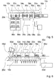
Weiter wird vorgeschlagen, dass die Führungseinheit zumindest einen Primärteil und die Förderelemente jeweils zumindest einen Sekundärteil eines Linearmotorsystems enthalten. Unter einem „Primärteil“ eines Linearmotorsystems soll in diesem Zusammenhang insbesondere ein fest stehender, Elektromagnete aufweisender Stator eines Linearmotors verstanden werden. Unter einem „Sekundärteil“ eines Linearmotorsystems soll in diesem Zusammenhang insbesondere ein bevorzugt durch Permanentmagnete gebildeter, einem Rotor eines rotierenden Motors entsprechender, beweglicher Teil eines Linearmotors verstanden werden. Unter einem „Linearmotorsystem“ soll in diesem Zusammenhang insbesondere ein System verstanden werden, welches aus zumindest einem Primärteil und einer Vielzahl von zumindest einem Primärteil bewegbaren Sekundärteilen besteht. Das Linearmotorsystem verfügt bevorzugt über Wegmess- und Positionsmesseinrichtungen, um den Ort und/oder die Geschwindigkeit der Sekundärteile zu ermitteln. Solche Linearmotorsysteme sind dem Fachmann bekannt. Die Förderelemente können besonders einfach und/oder dynamisch unabhängig geschwindigkeits- und/oder positionsgeregelt antreibbar sein. Die Zufuhrvorrichtung kann besonders leistungsfähig sein. Besonders bevorzugt enthalten Stützelemente ebenfalls zumindest einen Sekundärteil des Linearmotorsystems. Die Führungseinheit kann ein Primärteil enthalten, das sich entlang des gesamten Umlaufs der Förderelemente erstreckt. Bevorzugt enthält die Führungseinheit in Arbeitsabschnitten zumindest ein Primärteil, das zum geschwindigkeits- und/oder positionsgeregelten Antrieb der Förderelemente vorgesehen sind. Abschnitte des Umlaufs außerhalb von Arbeitsabschnitten können bevorzugt alternative Antriebsvorrichtungen für Förderelemente enthalten, insbesondere können die Förderelemente in zumindest in Teilen solcher Abschnitte durch Stau und/oder umlaufende Fördermittel, wie zum Beispiel Ketten und/oder Räder, durch Reib- und/oder Kraftschluss angetrieben werden. Abschnitte der Führungseinheit außerhalb von Arbeitsabschnitten können besonders kostengünstig sein. Weiter wird vorgeschlagen, dass die Steuereinheit dazu vorgesehen ist, Regelgrößen, insbesondere Antriebsströme der Förderelemente und/oder eine Regelabweichung der Förderelemente, insbesondere von Soll-/Istwerten von Positionen und/oder Geschwindigkeiten, zur Ermittlung eines Wartungszustands der Zufuhrvorrichtung zu nutzen. Insbesondere können im Mittel steigende Antriebsströme und/oder Regelabweichungen Hinweise auf eine Verschmutzung und/oder Abnutzung der Zufuhrvorrichtung und/oder auf Änderungen eines Magnetspalts zwischen Primär- und Sekundärteil und/oder den Verlust und/oder eine Beschädigung und/oder eine Abschwächung von Magneten des Sekundärteils sein. Die Steuereinheit kann bevorzugt eine beginnende Verschlechterung des Wartungszustands rechtzeitig vor einem Ausfall der Zufuhrvorrichtung erkennen. Der Wartungszustand kann einem Bediener signalisiert werden, so dass rechtzeitig Wartungsmaßnahmen eingeleitet werden können. Ungeplante Stillstände der Zufuhrvorrichtung durch mangelnde Wartung und/oder Defekte können reduziert werden. It is further proposed that the guide unit contain at least one primary part and the conveying elements each contain at least one secondary part of a linear motor system. In this context, a "primary part" of a linear motor system is to be understood as meaning, in particular, a stationary stator of a linear motor which has electromagnets. In this context, a "secondary part" of a linear motor system is to be understood as meaning, in particular, a movable part of a linear motor formed by permanent magnets and corresponding to a rotor of a rotating motor. A "linear motor system" is to be understood in this context in particular as a system which consists of at least one primary part and a plurality of at least one primary part movable secondary parts. The linear motor system preferably has displacement measuring and position measuring devices in order to determine the location and / or the speed of the secondary parts. Such linear motor systems are known to the person skilled in the art. The conveying elements can be particularly easily and / or dynamically independently driven in terms of speed and / or position. The feeder can be particularly powerful. Particularly preferably support elements also contain at least one secondary part of the linear motor system. The guide unit may include a primary part which extends along the entire circulation of the conveying elements. Preferably, the guide unit contains in working sections at least one primary part, which are provided for speed and / or position-controlled drive of the conveying elements. Portions of the circulation outside of working sections may preferably contain alternative drive devices for conveying elements, in particular the conveying elements may be at least in parts of such sections by jamming and / or revolving funding, such as chains and / or wheels, by friction and / or adhesion are driven. Sections of the guide unit outside work sections can be particularly inexpensive. It is further proposed that the control unit be provided to use controlled variables, in particular drive currents of the conveying elements and / or a control deviation of the conveying elements, in particular setpoint / actual values of positions and / or speeds, for determining a maintenance state of the feed device. In particular, increasing drive currents and / or system deviations can indicate signs of contamination and / or wear of the supply device and / or changes in a magnetic gap between the primary and secondary parts and / or the loss and / or damage and / or weakening of the magnet Abutment be. The control unit may preferably detect an incipient deterioration of the maintenance condition in good time prior to a failure of the delivery device. The maintenance status can be signaled to an operator, so that timely maintenance measures can be initiated. Unplanned shutdowns of the feeder due to lack of maintenance and / or defects can be reduced.
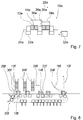
Weiter wird vorgeschlagen, dass die Halter und/oder Gegenhalter dazu vorgesehen sind, Produkte und/oder Produktstapel aus einer zugeführten Produktkolonne zu separieren. Unter einer „Produktkolonne“ soll in diesem Zusammenhang insbesondere ein endloser, bevorzugt horizontaler Stapel von Produkten verstanden werden. Die Produktkolonne kann zum Beispiel aus scheibenförmigen, horizontal gestapelten oder geschindelten Produkten, wie zum Beispiel Biskuits, bestehen. Die Produktkolonne wird bevorzugt entlang einer Zufuhrbahn zugeführt. Bevorzugt können der Halter und der Gegenhalter Produkte und/oder Produktstapel von der Produktkolonne separieren, indem der Halter und ein entgegen der Förderrichtung folgender Gegenhalter zwischen zwei Produkte der Produktkolonne geschoben werden. Der Halter kann aus der Produktkolonne ein Produkt und/oder einen Produktstapel abtrennen, indem er gegenüber dem Gegenhalter beschleunigt und einen Abstand herstellt. Der Gegenhalter sichert das Ende der Produktkolonne. Entgegen der Förderrichtung nachfolgende Halter/Gegenhalter können den nächsten Produktstapel abtrennen. Bevorzugt sind die Gegenhalter der Förderelemente mit Gegenhalter in einem Endbereich in Förderrichtung an den Förderelemente angeordnet. Bevorzugt sind die Halter der Förderelemente mit Halter in einem Endbereich entgegen der Förderrichtung an den Förderelemente angeordnet. Unter einem "Endbereich" des Förderelements soll in diesem Zusammenhang insbesondere ein Bereich verstanden werden, der sich ausgehend von einem Ende des Förderelements um weniger als 10%, bevorzugt weniger als 5% einer Länge des Förderelements in Richtung eines Zentrums des Förderelements erstreckt. Besonders bevorzugt begrenzen die Gegenhalter die Förderelemente mit Gegenhalter in Förderrichtung. Besonders bevorzugt begrenzen die Halter die Förderelemente mit Halter entgegen der Förderrichtung. Halter und Gegenhalter können so zu einem besonders geringen Abstand zusammengefahren werden. Ein Separieren der Produktkolonne durch Einschieben eines Halters und eines Gegenhalters kann erleichtert sein. Der Halter und/oder Gegenhalter kann am Förderelement bevorzugt in einer Richtung senkrecht zur Förderrichtung verschiebbar gelagert sein. Eine Kulissensteuerung und/oder ein Aktor kann dazu vorgesehen sein, den Halter im Produktübernahmebereich zwischen zwei Produkte der Produktkolonne zu bewegen. Halter und Gegenhalter können vorteilhaft zwischen zwei Produkte der Produktkolonne geschoben werden. In einer bevorzugten Ausgestaltung der Erfindung kann die Führungseinheit die Förderelemente zumindest in einem Teil des Produktübernahmebereichs entlang einer Bahn führen, die sich entlang einer Förderrichtung der Zufuhrbahn der Produktkolonne bevorzugt bezogen auf die Gewichtskraft von unten annähert. Die Förderelemente und Halter und Gegenhalter können sich bezogen auf die Gewichtskraft von unten den Produkten der Produktkolonne annähern und zwischen zwei Produkte der Produktkolonne gefahren werden, um diese zu separieren. Auf Aktoren zum Bewegen der Halter und/oder Gegenhalter zum Anheben und/oder Absenken der Halter und/oder Gegenhalter an den Förderelementen oder eine Kulissensteuerung kann verzichtet werden. Besonders bevorzugt kann ein Aktor und/oder eine Kulissensteuerung dazu vorgesehen sein, Gegenhalter und/oder Halter zumindest während des Eintauchens gegenüber den Förderelementen um einen Winkel zu schwenken. Es kann ein optimaler Winkel zwischen Halter und/oder Gegenhalter und Produkten der Produktkolonne während dem Einführen des Halters- und/oder Gegenhalters sichergestellt werden. Insbesondere kann der Halter und/oder Gegenhalter während des Einführens einen rechten Winkel zu einem Ende der Produktkolonne einnehmen. Die Produktkolonne kann besonders schonend separiert werden.It is further proposed that the holders and / or counter-holders are intended to separate products and / or product stacks from a supplied product column. In this context, a "product column" is to be understood as meaning, in particular, an endless, preferably horizontal stack of products. The product column may consist, for example, of disc-shaped, horizontally stacked or shingled products, such as biscuits. The product column is preferably fed along a feed path. Preferably, the holder and the counter-holder can separate products and / or product stacks from the product column by pushing the holder and a counter-holder following the conveying direction between two products of the product column. The holder can separate a product and / or a product stack from the product column by accelerating with respect to the anvil and making a distance. The counterpart ensures the end of the product column. Contrary to the conveying direction following holder / counter holder can separate the next product stack. Preferably, the counter-holders of the conveying elements with counter-holders are arranged in an end region in the conveying direction on the conveying elements. Preferably, the holders of the conveying elements with holders are arranged in an end region opposite to the conveying direction on the conveying elements. In this context, an "end region" of the conveying element should be understood to mean, in particular, a region which extends from one end of the conveying element by less than 10%, preferably less than 5%, of a length of the conveying element in the direction of a center of the conveying element. Particularly preferably, the counter holders limit the conveying elements with counter-holders in the conveying direction. Particularly preferably, the holders limit the conveying elements with holders counter to the conveying direction. Holder and counter holder can be moved together to a very small distance. Separating the product column by inserting a holder and a counter-holder can be facilitated. The holder and / or counter-holder may preferably be displaceably mounted on the conveying element in a direction perpendicular to the conveying direction. A slide control and / or an actuator can be provided to move the holder in the product transfer area between two products of the product column. Holder and counter-holder can be advantageously pushed between two products of the product column. In a preferred embodiment of the invention, the guide unit may guide the conveying elements at least in a part of the product transfer area along a path which approaches the feed line of the product column preferably along a conveying direction of the bottom from below. The conveying elements and holders and counter-holders can approach the products of the product column from below based on the weight force and can be moved between two products of the product column in order to separate them. On actuators for moving the holder and / or counter-holder for raising and / or lowering the holder and / or counter-holder on the conveyor elements or a link control can be dispensed with. Particularly preferably, an actuator and / or a link control can be provided to pivot the counter-holder and / or holder at least during the dipping with respect to the conveying elements by an angle. An optimum angle between holder and / or counter-holder and products of the product column during insertion of the holder and / or counter-holder can be ensured. In particular, the holder and / or counter-holder during insertion can take a right angle to one end of the product column. The product column can be separated very gently.
Weiter wird eine Verpackungsmaschine mit einer Zufuhrvorrichtung vorgeschlagen. Die Verpackungsmaschine kann besonders leistungsfähig sein. Furthermore, a packaging machine with a feed device is proposed. The packaging machine can be particularly powerful.
Weiter wird ein Verfahren zum Zuführen von Produkten oder Produktstapeln zu einer Verpackungsmaschine mit der Zufuhrvorrichtung mit den beschriebenen Verfahrensmerkmalen vorgeschlagen. Produkte oder Produktstapel können mit den beschriebenen Vorteilen zugeführt werden. Furthermore, a method is proposed for feeding products or product stacks to a packaging machine having the feeding device with the described method features. Products or product stacks can be supplied with the described advantages.
Zeichnung drawing
Weitere Vorteile ergeben sich aus der folgenden Zeichnungsbeschreibung. In den Zeichnungen sind Ausführungsbeispiele der Erfindung dargestellt. Die Zeichnungen, die Beschreibung und die Ansprüche enthalten zahlreiche Merkmale in Kombination. Der Fachmann wird die Merkmale zweckmäßigerweise auch einzeln betrachten und zu sinnvollen weiteren Kombinationen zusammenfassen.Further advantages emerge from the following description of the drawing. In the drawings, embodiments of the invention are shown. The drawings, the description and the claims contain numerous features in combination. The person skilled in the art will expediently also consider the features individually and combine them into meaningful further combinations.
Es zeigt:It shows:
Beschreibung der AusführungsbeispieleDescription of the embodiments
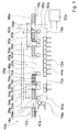
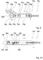
Die Zufuhrvorrichtung
Eine Länge des Pufferabschnitts
Die Verpackungsmaschine
Zum Antrieb der Förderelemente
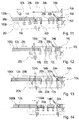
Die nachfolgende Beschreibung und die Zeichnungen weiterer Ausführungsbeispiele beschränkt sich im Wesentlichen auf die Unterschiede zwischen den Ausführungsbeispielen, wobei bezüglich gleich bezeichneter Bauteile, insbesondere in Bezug auf Bauteile mit gleichen Bezugszeichen, grundsätzlich auch auf die Zeichnungen und/oder die Beschreibung der anderen Ausführungsbeispiele verwiesen werden kann. Zur Unterscheidung der Ausführungsbeispiele sind anstelle des Buchstabens a des ersten Ausführungsbeispiels die Buchstaben b bis k den weiteren Ausführungsbeispielen nachgestellt.The following description and the drawings of further exemplary embodiments are essentially limited to the differences between the exemplary embodiments, reference being made in principle also to the drawings and / or the description of the other exemplary embodiments with respect to identically named components, in particular with regard to components having the same reference numbers , To distinguish the embodiments, instead of the letter a of the first embodiment, the letters b to k are adapted to the other embodiments.
ZITATE ENTHALTEN IN DER BESCHREIBUNG QUOTES INCLUDE IN THE DESCRIPTION
Diese Liste der vom Anmelder aufgeführten Dokumente wurde automatisiert erzeugt und ist ausschließlich zur besseren Information des Lesers aufgenommen. Die Liste ist nicht Bestandteil der deutschen Patent- bzw. Gebrauchsmusteranmeldung. Das DPMA übernimmt keinerlei Haftung für etwaige Fehler oder Auslassungen.This list of the documents listed by the applicant has been generated automatically and is included solely for the better information of the reader. The list is not part of the German patent or utility model application. The DPMA assumes no liability for any errors or omissions.
Zitierte PatentliteraturCited patent literature
- WO 03/105324 [0001] WO 03/105324 [0001]
Claims (12)
Priority Applications (9)
| Application Number | Priority Date | Filing Date | Title |
|---|---|---|---|
| DE102012210329A DE102012210329A1 (en) | 2012-06-19 | 2012-06-19 | feeding apparatus |
| US14/408,150 US9327855B2 (en) | 2012-06-19 | 2013-05-03 | Feeding device for packaging machine |
| PCT/EP2013/059225 WO2013189656A1 (en) | 2012-06-19 | 2013-05-03 | Feeding device for packaging machine |
| CN201380032805.8A CN104603012B (en) | 2012-06-19 | 2013-05-03 | Infeed equipment for packer |
| IN10180DEN2014 IN2014DN10180A (en) | 2012-06-19 | 2013-05-03 | |
| EP13724186.5A EP2861496B1 (en) | 2012-06-19 | 2013-05-03 | Feeding device for packaging machine |
| BR112014031240-0A BR112014031240B1 (en) | 2012-06-19 | 2013-05-03 | feeding device for feeding products and / or product stacks in a packaging process, packaging machine and process for feeding products or product stacks |
| JP2015516524A JP2015525176A (en) | 2012-06-19 | 2013-05-03 | Feeding equipment for packaging machines |
| JP2017102461A JP6453383B2 (en) | 2012-06-19 | 2017-05-24 | Feeding equipment for packaging machines |
Applications Claiming Priority (1)
| Application Number | Priority Date | Filing Date | Title |
|---|---|---|---|
| DE102012210329A DE102012210329A1 (en) | 2012-06-19 | 2012-06-19 | feeding apparatus |
Publications (1)
| Publication Number | Publication Date |
|---|---|
| DE102012210329A1 true DE102012210329A1 (en) | 2013-12-19 |
Family
ID=48470915
Family Applications (1)
| Application Number | Title | Priority Date | Filing Date |
|---|---|---|---|
| DE102012210329A Withdrawn DE102012210329A1 (en) | 2012-06-19 | 2012-06-19 | feeding apparatus |
Country Status (8)
| Country | Link |
|---|---|
| US (1) | US9327855B2 (en) |
| EP (1) | EP2861496B1 (en) |
| JP (2) | JP2015525176A (en) |
| CN (1) | CN104603012B (en) |
| BR (1) | BR112014031240B1 (en) |
| DE (1) | DE102012210329A1 (en) |
| IN (1) | IN2014DN10180A (en) |
| WO (1) | WO2013189656A1 (en) |
Cited By (15)
| Publication number | Priority date | Publication date | Assignee | Title |
|---|---|---|---|---|
| WO2016003945A1 (en) * | 2014-06-30 | 2016-01-07 | The Procter & Gamble Company | Packaging equipment for rolled paper products |
| DE102014225529A1 (en) * | 2014-12-11 | 2016-06-16 | Robert Bosch Gmbh | Transport device for a packaging machine |
| EP3034441A1 (en) | 2014-12-17 | 2016-06-22 | UHLMANN PAC-SYSTEME GmbH & Co. KG | Transport device for transporting products |
| EP3050811A1 (en) * | 2015-01-28 | 2016-08-03 | Vancebuild Limited | Apparatus and method for feeding products to a flow wrapping machine |
| US20160280410A1 (en) * | 2013-11-22 | 2016-09-29 | A M Packaging Limited | Product packaging system |
| WO2017125219A1 (en) * | 2016-01-18 | 2017-07-27 | Krones Aktiengesellschaft | Device and method for grouping and combining articles into multiple packages with different package sizes |
| WO2017186619A1 (en) * | 2016-04-29 | 2017-11-02 | Weber Maschinenbau Gmbh Breidenbach | Method for moving portions |
| EP3266721A1 (en) * | 2016-07-04 | 2018-01-10 | MULTIVAC Marking & Inspection GmbH & Co. KG | Labelling machine and method for producing multipacks |
| EP3339221A3 (en) * | 2016-12-21 | 2018-10-10 | Weber Maschinenbau GmbH Breidenbach | Method and device for handling products |
| FR3073832A1 (en) * | 2017-11-22 | 2019-05-24 | C.E.R.M.E.X. Constructions Etudes Et Recherches De Materiels Pour L'emballage D'expedition | POSITIONING PRODUCTS DURING THE CONVEYANCE |
| EP3521219A1 (en) * | 2018-02-06 | 2019-08-07 | Krones Aktiengesellschaft | Transport device and method for adapting a transport device |
| WO2019179685A1 (en) * | 2018-03-21 | 2019-09-26 | Mulet Valles Tomas | Machine and method for positioning objects |
| WO2021178694A1 (en) * | 2020-03-04 | 2021-09-10 | Westrock Packaging Systems, Llc | Systems and methods for orienting packages |
| DE102015100444B4 (en) | 2015-01-13 | 2023-02-16 | Pester Pac Automation Gmbh | transport device |
| EP4253289A3 (en) * | 2022-03-31 | 2024-01-17 | CT PACK S.r.l. | Apparatus and method for conveying articles and plant and method for packaging said articles |
Families Citing this family (54)
| Publication number | Priority date | Publication date | Assignee | Title |
|---|---|---|---|---|
| DE102012212825A1 (en) * | 2012-07-20 | 2014-01-23 | Robert Bosch Gmbh | Product stacking device |
| EP2743192B1 (en) * | 2012-12-12 | 2016-09-14 | Tetra Laval Holdings & Finance S.A. | A unit for sequencing and guiding items |
| DE102013105919A1 (en) * | 2013-06-07 | 2014-12-11 | Khs Gmbh | Packing machine with speed compensation in front of the shrink tunnel |
| DE102013210633A1 (en) * | 2013-06-07 | 2014-12-11 | Hastamat Verpackungstechnik Gmbh | Method and device for producing packaging units in a tubular bag machine |
| EP3116790B1 (en) * | 2014-03-14 | 2019-06-19 | Gima S.p.A. | Packaging process and related working station |
| ES2608688T3 (en) | 2014-03-21 | 2017-04-12 | Cavanna S.P.A. | Conveyor for a packing line |
| FR3018789B1 (en) | 2014-03-24 | 2019-10-04 | Cermex Constructions Etudes Et Recherches De Materiels Pour L'emballage D'expedition | DEVICE AND METHOD FOR POSITIONING PRODUCTS |
| EP2962964A1 (en) * | 2014-07-03 | 2016-01-06 | Marel A/S | A tray feeding system and a method of operating such a tray feeding system |
| EP3109189B1 (en) | 2015-06-25 | 2018-10-31 | Sidel Participations | A transfer device for conveying packaging units |
| CN106467181B (en) * | 2015-08-14 | 2019-09-03 | 上海昱庄机械科技有限公司 | A kind of capture apparatus |
| NL2015466B1 (en) * | 2015-09-18 | 2017-04-19 | B V Machf Houdijk | System for introducing into a pack chain a packaging machine of groups of products for manufacturing rolls or packs of cookies, each of the group consisting of a predetermined number of individual products such as biscuits or cookies, as well as a synchronizing device and a transport device for such system. |
| JP6800573B2 (en) * | 2015-10-26 | 2020-12-16 | 大森機械工業株式会社 | Pillow wrapping machine |
| JP6615715B2 (en) * | 2016-08-08 | 2019-12-04 | 株式会社フジキカイ | Article supply equipment |
| JP6642907B2 (en) * | 2016-08-19 | 2020-02-12 | 大森機械工業株式会社 | Packaging system |
| JP6655502B2 (en) * | 2016-08-19 | 2020-02-26 | 大森機械工業株式会社 | Packaging system |
| WO2018049122A1 (en) | 2016-09-09 | 2018-03-15 | The Procter & Gamble Company | Systems and methods for producing customized products intermixed with mass produced products |
| EP3510459A2 (en) | 2016-09-09 | 2019-07-17 | The Procter and Gamble Company | System and method for independently routing container-loaded vehicles to create different finished products |
| EP3509979B1 (en) | 2016-09-09 | 2023-06-14 | The Procter & Gamble Company | System and method for independently routing vehicles and delivering containers and closures to unit operation stations |
| CA3035963C (en) | 2016-09-09 | 2023-10-24 | The Procter & Gamble Company | System and method for producing products based upon demand |
| EP3510457A1 (en) | 2016-09-09 | 2019-07-17 | The Procter and Gamble Company | Methods for simultaneously producing different products on a single production line |
| EP3509954B1 (en) | 2016-09-09 | 2021-10-20 | The Procter & Gamble Company | System and method for simultaneously filling containers with different fluent compositions |
| WO2018049104A1 (en) | 2016-09-09 | 2018-03-15 | The Procter & Gamble Company | System and method for simultaneously filling containers of different shapes and/or sizes |
| FI3513935T3 (en) * | 2016-09-14 | 2023-08-15 | Yoshino Gypsum Co | Cutting device and manufacturing apparatus comprising such a cutting device |
| DE102017205773A1 (en) * | 2017-04-05 | 2018-10-11 | Robert Bosch Gmbh | Device for aligning products, in particular for forming rows and / or groups from the products |
| CN107444841B (en) * | 2017-06-21 | 2023-04-11 | 安徽御流包装机械有限公司 | Double-chain transmission device and application thereof |
| JP6532511B2 (en) * | 2017-09-01 | 2019-06-19 | 株式会社藤村工業 | Intermittent pillow packing machine |
| JP6786114B2 (en) | 2017-09-29 | 2020-11-18 | 株式会社フジキカイ | Transport device |
| US10272585B1 (en) * | 2017-10-11 | 2019-04-30 | Paper Converting Machine Company | Tissue log saw conveyor with independent lane control cutting and variable conveyor flight length |
| US11225384B2 (en) | 2018-04-05 | 2022-01-18 | Graphic Packaging International, Llc | Packaging machine |
| CN109205244A (en) * | 2018-10-09 | 2019-01-15 | 凯尔信汽车零部件(京山)有限公司 | A kind of pre-inserted shear of material of band assembly |
| JP6896290B2 (en) * | 2018-10-24 | 2021-06-30 | 株式会社フジキカイ | Transport device |
| EP3670404B1 (en) * | 2018-12-20 | 2023-07-12 | Sidel Participations | Sterilization apparatus having a conveying apparatus |
| DE102018222786A1 (en) | 2018-12-21 | 2020-06-25 | Krones Ag | Process for the format adaptation of carriages on a linear motor system and linear motor system |
| IT201900002563A1 (en) * | 2019-02-22 | 2020-08-22 | A C M I Spa | METHOD AND PLANT FOR PACKAGING PACKAGES |
| JP2022530862A (en) * | 2019-04-19 | 2022-07-04 | テトラ ラバル ホールディングス アンド ファイナンス エス エイ | Packaging machine and methods for producing sealed packages |
| EP4003845B1 (en) | 2019-07-30 | 2024-04-17 | Anheuser-Busch InBev S.A. | An article picking and treating apparatus |
| JP7352074B2 (en) * | 2019-08-30 | 2023-09-28 | 澁谷工業株式会社 | Article group separation and accumulation device |
| EP4031472A1 (en) * | 2019-09-17 | 2022-07-27 | Fameccanica.Data S.p.A. | Packaging plant for groups of hygienic absorbent articles, transport apparatus and related methods |
| ES1244195Y1 (en) | 2019-11-28 | 2021-04-20 | Posimat Sa | MACHINE FOR AUTOMATIC OBJECTS POSITIONING |
| IT201900023463A1 (en) * | 2019-12-10 | 2021-06-10 | Sps Italiana Pack Systems S P A | Packaging line |
| JP7390907B2 (en) * | 2020-01-29 | 2023-12-04 | 株式会社京都製作所 | Conveyance device |
| IT202000008479A1 (en) | 2020-04-21 | 2021-10-21 | Kosme Srl Unipersonale | TRANSPORT DEVICE FOR TRANSPORTING CONTAINERS |
| CN111572906B (en) * | 2020-05-22 | 2021-09-14 | 振德医疗用品股份有限公司 | Online bag pressing and forming equipment |
| JP7453860B2 (en) * | 2020-06-22 | 2024-03-21 | 株式会社京都製作所 | transfer device |
| JP7429166B2 (en) * | 2020-07-08 | 2024-02-07 | 株式会社京都製作所 | Transport device for transported objects |
| IT202000030641A1 (en) * | 2020-12-14 | 2022-06-14 | Sps Italiana Pack Systems S P A | EQUIPMENT FOR THE HANDLING AND GROUPING OF FLAT PRODUCTS |
| EP4089040A1 (en) * | 2021-05-11 | 2022-11-16 | Fameccanica.Data S.p.A. | Adaptive carrier unit and transfer system |
| CN114030683B (en) * | 2021-11-29 | 2023-02-28 | 北京航星机器制造有限公司 | Automatic ceramic tile arranging device and automatic ceramic tile arranging method |
| DE102021133524A1 (en) * | 2021-12-16 | 2023-06-22 | Khs Gmbh | Method for pushing goods to be transported, pushing device and palletizing machine |
| CN114435895B (en) * | 2022-01-20 | 2023-07-21 | 江苏经贸职业技术学院 | Commodity warehouse-out counting statistics device |
| CN114537761A (en) * | 2022-03-11 | 2022-05-27 | 杭州中亚机械股份有限公司 | Grouping device and method |
| DE102022106160A1 (en) | 2022-03-16 | 2023-09-21 | Krones Aktiengesellschaft | Identification of movement devices of a linear electric drive conveyor |
| DE102022123046A1 (en) * | 2022-09-09 | 2024-03-14 | Krones Aktiengesellschaft | Device and method for forming container pulks |
| CN116040032B (en) * | 2023-04-01 | 2023-06-23 | 佛山市南海加藤利食品有限公司 | Quick-frozen food baling press |
Citations (3)
| Publication number | Priority date | Publication date | Assignee | Title |
|---|---|---|---|---|
| WO2003105324A1 (en) | 2002-06-05 | 2003-12-18 | Jacobs Automation Llc | Controlled motion system |
| DE60306680T2 (en) * | 2002-12-13 | 2006-11-16 | Tetra Laval Holdings & Finance S.A. | FEED DEVICE |
| DE102010018153A1 (en) * | 2010-04-22 | 2011-10-27 | Krones Ag | Transport device and transport method for container treatment plant and container treatment plant with such transport device |
Family Cites Families (19)
| Publication number | Priority date | Publication date | Assignee | Title |
|---|---|---|---|---|
| US4552261A (en) * | 1983-12-27 | 1985-11-12 | Standard-Knapp, Inc. | Article grouper for case packer |
| JPH0444501Y2 (en) * | 1985-11-07 | 1992-10-20 | ||
| GB9421177D0 (en) * | 1994-10-20 | 1994-12-07 | Riverwood Int Ltd | Spacing conveyor mechanism |
| US5893701A (en) * | 1996-06-13 | 1999-04-13 | Food Machinery Sales, Inc. | Method and apparatus for forming groups of work products |
| US6191507B1 (en) | 1997-05-02 | 2001-02-20 | Ats Automation Tooling Systems Inc. | Modular conveyor system having multiple moving elements under independent control |
| US7134258B2 (en) * | 2001-12-05 | 2006-11-14 | R.A. Jones & Co. Inc. | Packaging apparatus and methods |
| ITBO20020460A1 (en) * | 2002-07-18 | 2004-01-19 | Aetna Group Spa | DEVICE FOR THE SEPARATION OF GROUPS OF CONTINUOUSLY SUPPLIED PRODUCTS |
| DE10258447A1 (en) | 2002-12-13 | 2004-06-24 | Rovema Verpackungsmaschinen Gmbh | Device for transporting lumpy product comprises a chamber with an internal width provided between two walls arranged behind each other and having one wall which can be displaced along a guide in or against the transport direction |
| DE10341992A1 (en) | 2003-09-08 | 2005-03-31 | Optima Filling And Packaging Machines Gmbh | Stacking device |
| DE102004042474A1 (en) * | 2004-09-02 | 2006-03-23 | Krones Ag | Device for grouping general cargo |
| US7900766B2 (en) | 2006-07-14 | 2011-03-08 | Ishida Co., Ltd. | Conveyance device and packing device provided therewith |
| GB0616458D0 (en) | 2006-08-18 | 2006-09-27 | Meadwestvaco Packaging Systems | Metering apparatus with independent tool drive means |
| US7475768B2 (en) * | 2006-09-15 | 2009-01-13 | Ishida Co., Ltd. | Accumulation device and box packing system having same |
| DE102007014876B4 (en) * | 2007-03-26 | 2010-04-08 | Kba-Metronic Aktiengesellschaft | transport system |
| FR2919593B1 (en) * | 2007-07-30 | 2009-11-20 | Sidel Participations | DEVICE FOR FORMING LOTS OF SUBSTANTIALLY PARALLELEPIPEDIC OBJECTS CIRCULATING ON A CONVEYOR BELT |
| DE102007049424A1 (en) * | 2007-10-12 | 2009-04-23 | Bhs Corrugated Maschinen- Und Anlagenbau Gmbh | Corrugated strip transport device |
| DE102008040204A1 (en) * | 2008-07-07 | 2010-01-14 | Robert Bosch Gmbh | Transport device for use in horizontal tubular bag packaging machine for transporting e.g. pouch, has linear drive with linear route sections arranged parallel to conveying regions, and curved conveying regions formed in non-driven manner |
| DE102009029314A1 (en) | 2009-01-29 | 2010-08-05 | Robert Bosch Gmbh | transport device |
| IT1398557B1 (en) * | 2010-03-09 | 2013-03-01 | Eurosicma S P A | PLANT FOR TRAINING AND CONTINUOUS SYNCHRONIZED TRANSFER OF COMPACT GROUPS OF PRODUCTS COMBINED AMONG THEM AROUND THE TRANSFER PATH. |
-
2012
- 2012-06-19 DE DE102012210329A patent/DE102012210329A1/en not_active Withdrawn
-
2013
- 2013-05-03 JP JP2015516524A patent/JP2015525176A/en active Pending
- 2013-05-03 IN IN10180DEN2014 patent/IN2014DN10180A/en unknown
- 2013-05-03 CN CN201380032805.8A patent/CN104603012B/en active Active
- 2013-05-03 WO PCT/EP2013/059225 patent/WO2013189656A1/en active Application Filing
- 2013-05-03 BR BR112014031240-0A patent/BR112014031240B1/en not_active IP Right Cessation
- 2013-05-03 US US14/408,150 patent/US9327855B2/en active Active
- 2013-05-03 EP EP13724186.5A patent/EP2861496B1/en active Active
-
2017
- 2017-05-24 JP JP2017102461A patent/JP6453383B2/en active Active
Patent Citations (3)
| Publication number | Priority date | Publication date | Assignee | Title |
|---|---|---|---|---|
| WO2003105324A1 (en) | 2002-06-05 | 2003-12-18 | Jacobs Automation Llc | Controlled motion system |
| DE60306680T2 (en) * | 2002-12-13 | 2006-11-16 | Tetra Laval Holdings & Finance S.A. | FEED DEVICE |
| DE102010018153A1 (en) * | 2010-04-22 | 2011-10-27 | Krones Ag | Transport device and transport method for container treatment plant and container treatment plant with such transport device |
Cited By (26)
| Publication number | Priority date | Publication date | Assignee | Title |
|---|---|---|---|---|
| US20160280410A1 (en) * | 2013-11-22 | 2016-09-29 | A M Packaging Limited | Product packaging system |
| US9731854B2 (en) * | 2013-11-22 | 2017-08-15 | A M Packaging Limited | Product packaging system |
| WO2016003945A1 (en) * | 2014-06-30 | 2016-01-07 | The Procter & Gamble Company | Packaging equipment for rolled paper products |
| DE102014225529A1 (en) * | 2014-12-11 | 2016-06-16 | Robert Bosch Gmbh | Transport device for a packaging machine |
| US10087018B2 (en) | 2014-12-11 | 2018-10-02 | Robert Bosch Gmbh | Transporting apparatus for a packaging machine |
| US9604795B2 (en) | 2014-12-17 | 2017-03-28 | Uhlmann Pac-Systeme Gmbh & Co. Kg | Transport device for conveying products |
| CN105712047A (en) * | 2014-12-17 | 2016-06-29 | 乌尔曼包装系统有限责任及合伙两合公司 | Transport device for transporting products |
| EP3034441A1 (en) | 2014-12-17 | 2016-06-22 | UHLMANN PAC-SYSTEME GmbH & Co. KG | Transport device for transporting products |
| CN105712047B (en) * | 2014-12-17 | 2018-01-19 | 乌尔曼包装系统有限责任及合伙两合公司 | Conveying equipment for conveying products |
| DE102015100444B4 (en) | 2015-01-13 | 2023-02-16 | Pester Pac Automation Gmbh | transport device |
| EP3050811A1 (en) * | 2015-01-28 | 2016-08-03 | Vancebuild Limited | Apparatus and method for feeding products to a flow wrapping machine |
| US9751650B2 (en) | 2015-01-28 | 2017-09-05 | Vancebuild Limited | Apparatus and method relating to flow wrapping |
| WO2017125219A1 (en) * | 2016-01-18 | 2017-07-27 | Krones Aktiengesellschaft | Device and method for grouping and combining articles into multiple packages with different package sizes |
| WO2017186619A1 (en) * | 2016-04-29 | 2017-11-02 | Weber Maschinenbau Gmbh Breidenbach | Method for moving portions |
| CN107572027A (en) * | 2016-07-04 | 2018-01-12 | 玛蒂威克标记及检验有限公司 | The method of labelling machine and production multi-pack |
| US10773842B2 (en) | 2016-07-04 | 2020-09-15 | Multivac Marking & Inspection Gmbh & Co. Kg | Labeling machine and method of producing multipacks |
| EP3266721A1 (en) * | 2016-07-04 | 2018-01-10 | MULTIVAC Marking & Inspection GmbH & Co. KG | Labelling machine and method for producing multipacks |
| EP3339221A3 (en) * | 2016-12-21 | 2018-10-10 | Weber Maschinenbau GmbH Breidenbach | Method and device for handling products |
| FR3073832A1 (en) * | 2017-11-22 | 2019-05-24 | C.E.R.M.E.X. Constructions Etudes Et Recherches De Materiels Pour L'emballage D'expedition | POSITIONING PRODUCTS DURING THE CONVEYANCE |
| WO2019102134A1 (en) * | 2017-11-22 | 2019-05-31 | C.E.R.M.E.X. Constructions Etudes Et Recherches De Materiels Pour L'emballage D'expedition | Device for positioning products whilst said products are being conveyed |
| EP3521219A1 (en) * | 2018-02-06 | 2019-08-07 | Krones Aktiengesellschaft | Transport device and method for adapting a transport device |
| WO2019179685A1 (en) * | 2018-03-21 | 2019-09-26 | Mulet Valles Tomas | Machine and method for positioning objects |
| US11273993B2 (en) | 2018-03-21 | 2022-03-15 | Tomas Mulet Valles | Machine and method for positioning objects |
| WO2021178694A1 (en) * | 2020-03-04 | 2021-09-10 | Westrock Packaging Systems, Llc | Systems and methods for orienting packages |
| US20230097636A1 (en) * | 2020-03-04 | 2023-03-30 | Westrock Packaging Systems, Llc | Systems and methods for orienting packages |
| EP4253289A3 (en) * | 2022-03-31 | 2024-01-17 | CT PACK S.r.l. | Apparatus and method for conveying articles and plant and method for packaging said articles |
Also Published As
| Publication number | Publication date |
|---|---|
| JP6453383B2 (en) | 2019-01-16 |
| US20150136564A1 (en) | 2015-05-21 |
| JP2015525176A (en) | 2015-09-03 |
| BR112014031240A2 (en) | 2017-06-27 |
| CN104603012A (en) | 2015-05-06 |
| WO2013189656A1 (en) | 2013-12-27 |
| EP2861496B1 (en) | 2017-09-27 |
| BR112014031240B1 (en) | 2021-01-12 |
| JP2017165490A (en) | 2017-09-21 |
| CN104603012B (en) | 2016-10-12 |
| US9327855B2 (en) | 2016-05-03 |
| EP2861496A1 (en) | 2015-04-22 |
| IN2014DN10180A (en) | 2015-08-21 |
Similar Documents
| Publication | Publication Date | Title |
|---|---|---|
| EP2861496B1 (en) | Feeding device for packaging machine | |
| EP2874888B1 (en) | Product stacking device | |
| EP2767494B1 (en) | Device for laying out printed products fed in a single product flow into two separate stacks | |
| EP2212225B1 (en) | Multiplex grouping device | |
| DE102014106400A1 (en) | INDIVIDUAL TRANSPORT OF FOOD PORTIONS | |
| EP3288731B1 (en) | Cutting device | |
| EP3059190A1 (en) | Device and method for distributing and grouping containers | |
| WO2016071062A1 (en) | Individual transport of portions of food | |
| DE102015209613A1 (en) | transport device | |
| DE102007021146A1 (en) | Apparatus and method for handling flat objects, in particular diapers | |
| DE102009019462A1 (en) | Method and device for generating formatted complete packages | |
| DE10005752A1 (en) | Assembly for stacking large sheet plate components from a press station has direction change points to divert the pressed workpieces into two or more stacking belts in a start/stop feed to gripping transfer units or for manual removal | |
| EP2921436A1 (en) | Tube body transfer system, tube body production device and tube body transfer method | |
| DE102017206970A1 (en) | Device and method for transporting products, in particular for packaging machines | |
| WO2020094318A1 (en) | Device for grouping containers | |
| DE102014005942A1 (en) | Method for grouping articles into article poles and grouping device and packaging machine with such | |
| EP2343521B1 (en) | Method and device for detection of goods on a conveyor line | |
| DE1936371C3 (en) | Device for conveying away finished stacks of printed matter | |
| EP0529204A1 (en) | Apparatus for conveying plates towards a deep drawing machine | |
| DE102008048831A1 (en) | Conveying device for packaging machine, has buffer conveyor, on which containers are conveyed, and collecting conveyor, through which containers are brought in predetermined distance to each other | |
| EP1155992B1 (en) | Method and device for dividing a transport stream of articles | |
| DE102020125269A1 (en) | Device for moving objects | |
| CH702211A1 (en) | The method and corresponding device for the intermediate storage of products. | |
| WO2017186620A1 (en) | Device for moving products | |
| DE10311053A1 (en) | A method for packing a selected number of mixed products into containers has an endless conveyor with one side co-operating with a linear conveyor carrying the containers |
Legal Events
| Date | Code | Title | Description |
|---|---|---|---|
| R163 | Identified publications notified | ||
| R005 | Application deemed withdrawn due to failure to request examination |