JP6883459B2 - Organic wastewater treatment method and organic wastewater treatment equipment - Google Patents
Organic wastewater treatment method and organic wastewater treatment equipment Download PDFInfo
- Publication number
- JP6883459B2 JP6883459B2 JP2017074763A JP2017074763A JP6883459B2 JP 6883459 B2 JP6883459 B2 JP 6883459B2 JP 2017074763 A JP2017074763 A JP 2017074763A JP 2017074763 A JP2017074763 A JP 2017074763A JP 6883459 B2 JP6883459 B2 JP 6883459B2
- Authority
- JP
- Japan
- Prior art keywords
- membrane separation
- organic wastewater
- separation device
- tank
- membrane
- Prior art date
- Legal status (The legal status is an assumption and is not a legal conclusion. Google has not performed a legal analysis and makes no representation as to the accuracy of the status listed.)
- Active
Links
Images


Classifications
-
- C—CHEMISTRY; METALLURGY
- C02—TREATMENT OF WATER, WASTE WATER, SEWAGE, OR SLUDGE
- C02F—TREATMENT OF WATER, WASTE WATER, SEWAGE, OR SLUDGE
- C02F3/00—Biological treatment of water, waste water, or sewage
- C02F3/30—Aerobic and anaerobic processes
- C02F3/302—Nitrification and denitrification treatment
- C02F3/303—Nitrification and denitrification treatment characterised by the nitrification
-
- C—CHEMISTRY; METALLURGY
- C02—TREATMENT OF WATER, WASTE WATER, SEWAGE, OR SLUDGE
- C02F—TREATMENT OF WATER, WASTE WATER, SEWAGE, OR SLUDGE
- C02F3/00—Biological treatment of water, waste water, or sewage
- C02F3/30—Aerobic and anaerobic processes
- C02F3/302—Nitrification and denitrification treatment
-
- C—CHEMISTRY; METALLURGY
- C02—TREATMENT OF WATER, WASTE WATER, SEWAGE, OR SLUDGE
- C02F—TREATMENT OF WATER, WASTE WATER, SEWAGE, OR SLUDGE
- C02F3/00—Biological treatment of water, waste water, or sewage
- C02F3/006—Regulation methods for biological treatment
-
- C—CHEMISTRY; METALLURGY
- C02—TREATMENT OF WATER, WASTE WATER, SEWAGE, OR SLUDGE
- C02F—TREATMENT OF WATER, WASTE WATER, SEWAGE, OR SLUDGE
- C02F3/00—Biological treatment of water, waste water, or sewage
- C02F3/02—Aerobic processes
- C02F3/12—Activated sludge processes
- C02F3/1205—Particular type of activated sludge processes
- C02F3/1215—Combinations of activated sludge treatment with precipitation, flocculation, coagulation and separation of phosphates
-
- C—CHEMISTRY; METALLURGY
- C02—TREATMENT OF WATER, WASTE WATER, SEWAGE, OR SLUDGE
- C02F—TREATMENT OF WATER, WASTE WATER, SEWAGE, OR SLUDGE
- C02F3/00—Biological treatment of water, waste water, or sewage
- C02F3/02—Aerobic processes
- C02F3/12—Activated sludge processes
- C02F3/1236—Particular type of activated sludge installations
- C02F3/1268—Membrane bioreactor systems
- C02F3/1273—Submerged membrane bioreactors
-
- C—CHEMISTRY; METALLURGY
- C02—TREATMENT OF WATER, WASTE WATER, SEWAGE, OR SLUDGE
- C02F—TREATMENT OF WATER, WASTE WATER, SEWAGE, OR SLUDGE
- C02F3/00—Biological treatment of water, waste water, or sewage
- C02F3/02—Aerobic processes
- C02F3/12—Activated sludge processes
- C02F3/20—Activated sludge processes using diffusers
-
- C—CHEMISTRY; METALLURGY
- C02—TREATMENT OF WATER, WASTE WATER, SEWAGE, OR SLUDGE
- C02F—TREATMENT OF WATER, WASTE WATER, SEWAGE, OR SLUDGE
- C02F3/00—Biological treatment of water, waste water, or sewage
- C02F3/02—Aerobic processes
- C02F3/12—Activated sludge processes
- C02F3/22—Activated sludge processes using circulation pipes
- C02F3/223—Activated sludge processes using circulation pipes using "air-lift"
-
- C—CHEMISTRY; METALLURGY
- C02—TREATMENT OF WATER, WASTE WATER, SEWAGE, OR SLUDGE
- C02F—TREATMENT OF WATER, WASTE WATER, SEWAGE, OR SLUDGE
- C02F3/00—Biological treatment of water, waste water, or sewage
- C02F3/30—Aerobic and anaerobic processes
- C02F3/302—Nitrification and denitrification treatment
- C02F3/305—Nitrification and denitrification treatment characterised by the denitrification
-
- C—CHEMISTRY; METALLURGY
- C02—TREATMENT OF WATER, WASTE WATER, SEWAGE, OR SLUDGE
- C02F—TREATMENT OF WATER, WASTE WATER, SEWAGE, OR SLUDGE
- C02F2209/00—Controlling or monitoring parameters in water treatment
- C02F2209/005—Processes using a programmable logic controller [PLC]
-
- C—CHEMISTRY; METALLURGY
- C02—TREATMENT OF WATER, WASTE WATER, SEWAGE, OR SLUDGE
- C02F—TREATMENT OF WATER, WASTE WATER, SEWAGE, OR SLUDGE
- C02F2209/00—Controlling or monitoring parameters in water treatment
- C02F2209/03—Pressure
-
- C—CHEMISTRY; METALLURGY
- C02—TREATMENT OF WATER, WASTE WATER, SEWAGE, OR SLUDGE
- C02F—TREATMENT OF WATER, WASTE WATER, SEWAGE, OR SLUDGE
- C02F2209/00—Controlling or monitoring parameters in water treatment
- C02F2209/14—NH3-N
-
- C—CHEMISTRY; METALLURGY
- C02—TREATMENT OF WATER, WASTE WATER, SEWAGE, OR SLUDGE
- C02F—TREATMENT OF WATER, WASTE WATER, SEWAGE, OR SLUDGE
- C02F2209/00—Controlling or monitoring parameters in water treatment
- C02F2209/16—Total nitrogen (tkN-N)
-
- C—CHEMISTRY; METALLURGY
- C02—TREATMENT OF WATER, WASTE WATER, SEWAGE, OR SLUDGE
- C02F—TREATMENT OF WATER, WASTE WATER, SEWAGE, OR SLUDGE
- C02F2209/00—Controlling or monitoring parameters in water treatment
- C02F2209/40—Liquid flow rate
-
- C—CHEMISTRY; METALLURGY
- C02—TREATMENT OF WATER, WASTE WATER, SEWAGE, OR SLUDGE
- C02F—TREATMENT OF WATER, WASTE WATER, SEWAGE, OR SLUDGE
- C02F2209/00—Controlling or monitoring parameters in water treatment
- C02F2209/42—Liquid level
-
- C—CHEMISTRY; METALLURGY
- C02—TREATMENT OF WATER, WASTE WATER, SEWAGE, OR SLUDGE
- C02F—TREATMENT OF WATER, WASTE WATER, SEWAGE, OR SLUDGE
- C02F2301/00—General aspects of water treatment
- C02F2301/04—Flow arrangements
- C02F2301/043—Treatment of partial or bypass streams
-
- C—CHEMISTRY; METALLURGY
- C02—TREATMENT OF WATER, WASTE WATER, SEWAGE, OR SLUDGE
- C02F—TREATMENT OF WATER, WASTE WATER, SEWAGE, OR SLUDGE
- C02F2301/00—General aspects of water treatment
- C02F2301/08—Multistage treatments, e.g. repetition of the same process step under different conditions
-
- C—CHEMISTRY; METALLURGY
- C02—TREATMENT OF WATER, WASTE WATER, SEWAGE, OR SLUDGE
- C02F—TREATMENT OF WATER, WASTE WATER, SEWAGE, OR SLUDGE
- C02F2303/00—Specific treatment goals
- C02F2303/16—Regeneration of sorbents, filters
-
- C—CHEMISTRY; METALLURGY
- C02—TREATMENT OF WATER, WASTE WATER, SEWAGE, OR SLUDGE
- C02F—TREATMENT OF WATER, WASTE WATER, SEWAGE, OR SLUDGE
- C02F3/00—Biological treatment of water, waste water, or sewage
- C02F3/02—Aerobic processes
- C02F3/12—Activated sludge processes
- C02F3/1205—Particular type of activated sludge processes
- C02F3/121—Multistep treatment
-
- C—CHEMISTRY; METALLURGY
- C02—TREATMENT OF WATER, WASTE WATER, SEWAGE, OR SLUDGE
- C02F—TREATMENT OF WATER, WASTE WATER, SEWAGE, OR SLUDGE
- C02F3/00—Biological treatment of water, waste water, or sewage
- C02F3/02—Aerobic processes
- C02F3/12—Activated sludge processes
- C02F3/1205—Particular type of activated sludge processes
- C02F3/1221—Particular type of activated sludge processes comprising treatment of the recirculated sludge
-
- C—CHEMISTRY; METALLURGY
- C02—TREATMENT OF WATER, WASTE WATER, SEWAGE, OR SLUDGE
- C02F—TREATMENT OF WATER, WASTE WATER, SEWAGE, OR SLUDGE
- C02F3/00—Biological treatment of water, waste water, or sewage
- C02F3/02—Aerobic processes
- C02F3/12—Activated sludge processes
- C02F3/1236—Particular type of activated sludge installations
- C02F3/1257—Oxidation ditches
-
- Y—GENERAL TAGGING OF NEW TECHNOLOGICAL DEVELOPMENTS; GENERAL TAGGING OF CROSS-SECTIONAL TECHNOLOGIES SPANNING OVER SEVERAL SECTIONS OF THE IPC; TECHNICAL SUBJECTS COVERED BY FORMER USPC CROSS-REFERENCE ART COLLECTIONS [XRACs] AND DIGESTS
- Y02—TECHNOLOGIES OR APPLICATIONS FOR MITIGATION OR ADAPTATION AGAINST CLIMATE CHANGE
- Y02W—CLIMATE CHANGE MITIGATION TECHNOLOGIES RELATED TO WASTEWATER TREATMENT OR WASTE MANAGEMENT
- Y02W10/00—Technologies for wastewater treatment
- Y02W10/10—Biological treatment of water, waste water, or sewage
Description
本発明は、有機性排水処理方法及び有機性排水処理装置に関する。 The present invention relates to an organic wastewater treatment method and an organic wastewater treatment apparatus.
特許文献1には、窒素除去率90%以上で、コンパクトな、窒素含有排液の処理設備を提供することを目的として、嫌気槽、好気槽の順に複数個の嫌気槽と好気槽が交互に直列に結合され、最前段の嫌気槽と2段目以降の少なくともひとつの嫌気槽に窒素含有排液を供給する供給経路を備え、最後段の好気槽には活性汚泥を分離して処理液を得るための浸漬型分離装置を備え、最後段の好気槽から最前段の嫌気槽へ活性汚泥液を返送する経路を備えた処理設備が開示されている。 Patent Document 1 describes a plurality of anaerobic tanks and aerobic tanks in the order of an anaerobic tank and an aerobic tank for the purpose of providing a compact nitrogen-containing wastewater treatment facility having a nitrogen removal rate of 90% or more. It is connected in series alternately and has a supply path for supplying nitrogen-containing wastewater to the anaerobic tank in the first stage and at least one anaerobic tank in the second and subsequent stages, and the activated sludge is separated in the aerobic tank in the last stage. A treatment facility including a dipping type separation device for obtaining a treatment liquid and a route for returning the activated sludge liquid from the aerobic tank at the last stage to the anaerobic tank at the front stage is disclosed.
特許文献2には、1槽の処理槽のみで高度処理を行う膜分離装置であって、被処理水が生物学的に処理されるとともに、前記被処理水の旋回流が形成される無端状の処理槽と、前記旋回流の流れ方向に間隔をあけて設置され、前記被処理水を膜分離処理する複数の膜ユニットと、前記処理槽に供給される被処理水が貯留される原水槽を備えた膜分離装置において、前記原水槽を前記旋回流の内側に設け、該原水槽から前記処理槽に前記被処理水を供給する供給手段が、前記旋回流の流れ方向において多段階的に供給を行うことを特徴とする膜分離装置が提案されている。
上述した何れの排水処理設備であっても、各分離膜が浸漬配置された好気性処理領域に隣接して形成される嫌気性処理領域に有機性排水が供給されるため、嫌気性処理領域において高BOD濃度下で高い脱窒処理性能が実現できる。 In any of the above-mentioned wastewater treatment facilities, since organic wastewater is supplied to the anaerobic treatment region formed adjacent to the aerobic treatment region in which each separation membrane is immersed and arranged, in the anaerobic treatment region. High denitrification treatment performance can be realized under high BOD concentration.
しかし、上述した排水処理設備に流入する有機性排水量や窒素含有量が変動する場合の対処方法や、分離膜にファウリング物質が堆積して膜間差圧が大きくなった場合に必要となる効果的な膜洗浄方法については開示されておらず、このような観点でさらに改良すべき点があった。 However, the effects required when the amount of organic wastewater flowing into the wastewater treatment equipment and the nitrogen content fluctuate as described above, and when the fouling substance is deposited on the separation membrane and the differential pressure between the membranes increases. No specific membrane cleaning method has been disclosed, and there are points to be further improved from this point of view.
本発明の目的は、窒素を含有する有機性排水の性状に応じて効率的に生物処理を行なうことができる有機性排水処理方法及び有機性排水処理装置を提供する点にある。 An object of the present invention is to provide an organic wastewater treatment method and an organic wastewater treatment apparatus capable of efficiently performing biological treatment according to the properties of nitrogen-containing organic wastewater.
上述の目的を達成するため、本発明による有機性排水処理方法の第一特徴構成は、特許請求の範囲の書類の請求項1に記載した通り、窒素を含む有機性排水を活性汚泥中で生物処理する有機性排水処理方法であって、有機性排水の流れに沿う上流側に配設された無酸素槽と下流側に配設され膜分離装置が活性汚泥中に浸漬配置された好気槽とを一対の生物処理単位とし、複数の生物処理単位が直列に接続された生物処理槽と、最下流に配設された好気槽から最上流に配設された無酸素槽へ活性汚泥を返送する汚泥返送経路と、を備えた有機性排水処理装置に対して、有機性排水を各生物処理単位の無酸素槽に分割して供給し、前記無酸素槽での脱窒処理と前記好気槽での硝化処理を繰り返しながら有機性排水を生物処理し、各生物処理単位の膜分離装置から膜透過液を処理水として送出し、有機性排水の流入量、水槽液位、各膜分離装置の膜間差圧、処理水のT-N、処理水のNH3-N濃度の少なくとも一つを指標として、前記生物処理単位毎に稼働中の膜分離装置の停止または停止中の膜分離装置の起動の可否を決定する点にある。 In order to achieve the above object, the first characteristic configuration of the organic wastewater treatment method according to the present invention is as described in claim 1 of the document in the scope of the patent claim, that the organic wastewater containing nitrogen is living in activated sludge. An aerobic tank arranged on the upstream side along the flow of organic wastewater and an aerobic tank arranged on the downstream side in which a membrane separator is immersed in activated sludge. Is a pair of biological treatment units, and activated sludge is transferred from the biological treatment tank in which multiple biological treatment units are connected in series and the aerobic tank arranged in the most downstream to the oxygen-free tank arranged in the most upstream. Organic wastewater is divided and supplied to an oxygen-free tank of each biological treatment unit to an organic wastewater treatment device equipped with a sludge return route to be returned, and denitrification treatment in the oxygen-free tank and the above-mentioned favorable conditions are performed. Organic wastewater is biologically treated while repeating the nitrification treatment in the air tank, and the membrane permeate is sent out as treated water from the membrane separator of each biological treatment unit, and the inflow amount of organic wastewater, water tank liquid level, and each membrane separation Using at least one of the intermembrane differential pressure of the device, the TN of the treated water, and the NH 3- N concentration of the treated water as indicators, the membrane separation device in operation is stopped or the film separation is stopped for each biological treatment unit. The point is to decide whether or not to start the device.
窒素を含有する有機性排水に対する硝化処理及び脱窒処理の負荷の程度に基づいて生物処理単位毎に稼働中の膜分離装置の停止または停止中の膜分離装置の起動の可否を決定することにより、膜分離装置に備えた曝気装置に要する動力の適正化を図ることができ、運転コストを低減することができるようになる。負荷の程度を計る指標として、有機性排水の流入量、水槽液位、各膜分離装置の膜間差圧、処理水のT-N、処理水のNH3-N濃度の少なくとも一つを用いることができる。 By deciding whether to stop the operating membrane separation device or start the stopped membrane separation device for each biological treatment unit based on the degree of load of nitrification treatment and denitrification treatment on nitrogen-containing organic wastewater. , The power required for the aeration device provided in the membrane separation device can be optimized, and the operating cost can be reduced. At least one of the inflow amount of organic wastewater, the water tank liquid level, the intermembrane differential pressure of each membrane separation device, the TN of the treated water, and the NH 3- N concentration of the treated water is used as an index for measuring the degree of load. be able to.
同第二の特徴構成は、同請求項2に記載した通り、上述の第一の特徴構成に加えて、前記膜分離装置の稼働状況に応じて、前記生物処理槽内の活性汚泥に注入する凝集剤の注入量を調整する点にある。
As described in
生物処理単位で膜分離装置を停止すると、該当する好気槽では曝気装置が停止するため、嫌気状態が強くなる。この状態の活性汚泥がさらに下流側に隣接する無酸素槽に流入すると、当該無酸素槽に供給される有機性排水の影響により活性汚泥からのリンの吐出しが顕著になる。そして、膜分離装置が稼働する好気槽における活性汚泥によるリンの過剰摂取が促進され、凝集剤の注入量を減量しても効率的にリンが除去されるようになり、脱窒処理に加えてリンの効率除去という高度処理が可能になる。 When the membrane separation device is stopped in the biological treatment unit, the aeration device is stopped in the corresponding aerobic tank, so that the anaerobic state becomes stronger. When the activated sludge in this state flows into the oxygen-free tank adjacent to the downstream side, the discharge of phosphorus from the activated sludge becomes remarkable due to the influence of the organic wastewater supplied to the oxygen-free tank. Then, the excessive intake of phosphorus by activated sludge in the aerobic tank in which the membrane separation device operates is promoted, and phosphorus can be efficiently removed even if the injection amount of the flocculant is reduced, and in addition to the denitrification treatment. It enables advanced processing called efficient removal of phosphorus.
同第三の特徴構成は、同請求項3に記載した通り、上述の第一または第二の特徴構成に加えて、前記膜分離装置を停止すると決定する場合に、停止対象となる膜分離装置を所定時間毎に切り替える点にある。 As described in claim 3, the third feature configuration is, in addition to the first or second feature configuration described above, a membrane separation device to be stopped when it is determined to stop the membrane separation device. Is at the point of switching at predetermined time intervals.
上述した指標により膜分離装置を停止する場合に、特定の膜分離装置を長時間にわたって停止すると、対応する好気槽の汚泥が腐敗する虞がある。そのような場合でも、停止対象となる膜分離装置を所定時間毎に切り替えることにより、特定の好気槽で汚泥が腐敗するようなこと無く、装置全体として適切に生物処理を行なうことができるようになる。 When the membrane separation device is stopped according to the above-mentioned index, if the specific membrane separation device is stopped for a long period of time, the sludge in the corresponding aerobic tank may be putrefactive. Even in such a case, by switching the membrane separation device to be stopped at predetermined time intervals, the sludge does not rot in a specific aerobic tank, and the device as a whole can appropriately perform biological treatment. become.
同第四の特徴構成は、同請求項4に記載した通り、上述の第三の特徴構成に加えて、停止中の膜分離装置に対して二次側から洗浄液を注入して膜洗浄する処理を全ての膜分離装置に対して順次実行し、全ての膜分離装置の洗浄が完了するまでの間は、洗浄済みの膜分離装置の膜ろ過流量を未洗浄の膜分離装置の膜ろ過流量以下に設定して運転する点にある。 As described in claim 4, the fourth feature configuration is a process of injecting a cleaning liquid from the secondary side into a stopped membrane separation device to perform membrane cleaning, in addition to the third feature configuration described above. Is sequentially executed for all the membrane separation devices, and the membrane filtration flow rate of the washed membrane separation device is equal to or less than the membrane filtration flow rate of the unwashed membrane separation device until the cleaning of all the membrane separation devices is completed. The point is to set it to and drive.
膜分離装置に備えた分離膜にファウリング物質が堆積して目詰まりするような事態に到ると、洗浄液を用いた膜洗浄処理が必要になる。膜洗浄処理された後の膜分離装置の膜間差圧は他の膜分離装置よりも小さくなるため、結果的に他の膜分離装置よりも膜ろ過量が増えて、早期に目詰まりを起こす虞がある。そのような場合でも、他の膜分離装置に対して順番に洗浄液を用いた膜洗浄処理を行ない、全ての膜分離装置に対する膜洗浄処理が終了するまでの間は、洗浄済みの膜分離装置の膜ろ過流量を未洗浄の膜分離装置の膜ろ過流量以下となるように設定して運転することにより、全体として安定した膜ろ過処理が行なえるようになる。 When a fouling substance is deposited on the separation membrane provided in the membrane separation device and becomes clogged, a membrane cleaning treatment using a cleaning liquid is required. Since the intermembrane differential pressure of the membrane separation device after the membrane cleaning treatment is smaller than that of other membrane separation devices, as a result, the amount of membrane filtration is larger than that of other membrane separation devices, causing early clogging. There is a risk. Even in such a case, the other membrane separation devices are sequentially subjected to the membrane cleaning treatment using the cleaning liquid, and until the membrane cleaning treatment for all the membrane separation devices is completed, the washed membrane separation device is used. By setting and operating the membrane filtration flow rate so as to be equal to or less than the membrane filtration flow rate of the unwashed membrane separation device, stable membrane filtration processing can be performed as a whole.
同第五の特徴構成は、同請求項5に記載した通り、上述の第一から第四の何れかの特徴構成に加えて、好気槽から無酸素槽へ活性汚泥が流出する流出部の開口上端は水没しており、活性汚泥の流入流速が0.5m/sec.以下である点にある。 As described in claim 5, the fifth characteristic configuration is, in addition to any of the first to fourth characteristic configurations described above, the outflow portion where activated sludge flows out from the aerobic tank to the oxygen-free tank. The upper end of the opening is submerged, and the inflow velocity of activated sludge is 0.5 m / sec. The points are as follows.
膜分離装置が浸漬配置された好気槽では、曝気装置から掃き出された気泡による上向流が発生し、水面近傍で溶存酸素濃度が高い状態になり、水面より底部に向けて次第に溶存酸素濃度が低下する。水面近傍の溶存酸素濃度が高い状態の活性汚泥が無酸素槽に流入すると脱窒効率が低下する虞があるが、流入部の開口の上端が水没するような位置に配置されていることにより、無酸素槽での脱窒効率の低下を抑制できるようになる。しかも、活性汚泥の流入部の開口の流速が0.5m/sec.以下に設定されていれば、活性汚泥が開口部を通過する際の圧力損失による好気槽と無酸素槽の水位差の発生を抑制することができ、各好気槽における活性汚泥に対する曝気の均一化を図ることができる。 In the aerobic tank in which the membrane separation device is immersed, an upward flow is generated by the bubbles swept out from the aeration device, and the dissolved oxygen concentration becomes high near the water surface, and the dissolved oxygen gradually reaches the bottom from the water surface. The concentration decreases. If activated sludge with a high dissolved oxygen concentration near the water surface flows into the oxygen-free tank, the denitrification efficiency may decrease. It becomes possible to suppress a decrease in denitrification efficiency in an oxygen-free tank. Moreover, the flow velocity of the opening of the inflow portion of the activated sludge is 0.5 m / sec. If it is set as follows, it is possible to suppress the occurrence of the water level difference between the aerobic tank and the anoxic tank due to the pressure loss when the activated sludge passes through the opening, and the aeration of the activated sludge in each aerobic tank. Uniformity can be achieved.
本発明による排水処理装置の第一特徴構成は、同請求項6に記載した通り、窒素を含む有機性排水を活性汚泥中で生物処理する有機性排水処理装置であって、有機性排水の流れに沿う上流側に配設された無酸素槽と下流側に配設され膜分離装置が活性汚泥中に浸漬配置された好気槽とを一対の生物処理単位とし、複数の生物処理単位を直列に接続する生物処理槽と、最下流に配設された好気槽から最上流に配設された無酸素槽へ活性汚泥を返送する汚泥返送経路と、有機性排水を各生物処理単位の無酸素槽に分割して供給する原水供給経路と、各生物処理単位の膜分離装置から膜透過液を処理水として送出する処理水送出経路と、有機性排水の流入量、水槽液位、各膜分離装置の膜間差圧、処理水のT-N、処理水のNH3-N濃度の少なくとも一つを測定する測定装置と、前記測定装置で得られた測定値を指標として、前記生物処理単位毎に稼働中の膜分離装置の停止または停止中の膜分離装置の起動の可否を判断する制御装置と、を備える点にある。 As described in claim 6, the first characteristic configuration of the wastewater treatment apparatus according to the present invention is an organic wastewater treatment apparatus for biologically treating organic wastewater containing nitrogen in active sludge, and the flow of organic wastewater. An oxygen-free tank arranged on the upstream side and an aerobic tank arranged on the downstream side and having a membrane separation device immersed in active sludge are used as a pair of biological treatment units, and a plurality of biological treatment units are connected in series. A biological treatment tank connected to, a sludge return route for returning active sludge from an aerobic tank arranged at the most downstream to an oxygen-free tank arranged at the most upstream, and no organic wastewater for each biological treatment unit. Raw water supply route divided into oxygen tanks, treated water delivery route to send membrane permeate as treated water from the membrane separation device of each biological treatment unit, inflow amount of organic wastewater, water tank liquid level, each membrane The biological treatment is carried out using a measuring device that measures at least one of the intermembrane differential pressure of the separation device, the TN of the treated water, and the NH 3-N concentration of the treated water, and the measured value obtained by the measuring device as an index. The point is that each unit is provided with a control device for determining whether or not to stop the operating membrane separation device or start the stopped membrane separation device.
同第二の特徴構成は、同請求項7に記載した通り、上述の第一の特徴構成に加えて、前記制御装置は、前記膜分離装置の稼働状況に応じて、前記生物処理槽内の活性汚泥に注入する凝集剤の注入量を調整する点にある。 As described in claim 7, the second feature configuration is, in addition to the first feature configuration described above, the control device in the biological treatment tank according to the operating status of the membrane separation device. The point is to adjust the injection amount of the flocculant to be injected into the activated sludge.
同第三の特徴構成は、同請求項8に記載した通り、上述の第一または第二の特徴構成に加えて、前記制御装置は、前記膜分離装置を停止すると決定した場合に、停止対象となる膜分離装置を所定時間毎に切り替える点にある。 As described in claim 8, the third feature configuration is, in addition to the first or second feature configuration described above, a stop target when the control device determines to stop the membrane separation device. The point is that the membrane separation device is switched at predetermined time intervals.
同第四の特徴構成は、同請求項9に記載した通り、上述の第一から第三の何れかの特徴構成に加えて、前記好気槽から有機性排水の流れに沿う下流側に隣接する前記無酸素槽へ向けて活性汚泥を送出する流出部の開口部の上端が、前記好気槽の水面から30cm以下の部位に位置している点にある。
As described in
好気槽に浸漬配置された膜分離装置を停止すると、槽内で活性汚泥が沈降するようになる。しかし、無酸素槽へ向けて活性汚泥を送出する流出部の開口部の上端が、前記好気槽の水面から30cm以下の部位に位置していると、上澄みだけが無酸素槽に流入するような不都合な状態を回避し、膜分離装置を停止した状態でも活性汚泥を無酸素槽へ向けて送出することができる。
When the membrane separation device immersed in the aerobic tank is stopped, activated sludge will settle in the tank. However, if the upper end of the opening of the outflow portion that sends the activated sludge toward the oxygen-free tank is located at a
以上説明した通り、本発明によれば、窒素を含有する有機性排水の性状に応じて効率的に生物処理を行なうことができる有機性排水処理方法及び有機性排水処理装置を提供することができるようになった。 As described above, according to the present invention, it is possible to provide an organic wastewater treatment method and an organic wastewater treatment apparatus capable of efficiently performing biological treatment according to the properties of nitrogen-containing organic wastewater. It became so.
以下、本発明による排水処理方法及び排水処理装置の実施形態を説明する。
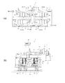
図1(a),(b)に示すように、排水処理装置1は、原水である窒素を含む有機性排水を活性汚泥中で生物処理して処理水を得る有機性排水処理装置であり、一対の無酸素槽10と好気槽20を生物処理単位として、複数の生物処理単位(本実施形態では4対の生物処理単位)を有機性排水の流れに沿って直列に且つ無終端状に配置した生物処理槽2を備えている。
Hereinafter, the wastewater treatment method and the embodiment of the wastewater treatment apparatus according to the present invention will be described.
As shown in FIGS. 1A and 1B, the wastewater treatment device 1 is an organic wastewater treatment device that obtains treated water by biologically treating organic wastewater containing nitrogen, which is raw water, in activated sludge. A pair of
なお、単一の生物処理槽2を複数領域に仕切ることにより複数の生物処理単位を構成してもよいし、有機性排水の流れに沿って個別の無酸素槽10と好気槽20を複数対配列することにより生物処理槽2を構成してもよい。
A plurality of biological treatment units may be formed by partitioning a single
また、生物処理槽2を直線状に構成し、最下流の好気槽20から最上流の無酸素槽10へ活性汚泥を返送するための汚泥返送経路としての水路または管路を別途設けてもよい。
Further, even if the
原水である有機性排水が原水供給経路3を介して各無酸素槽10に略等量に分割して供給され、各無酸素槽10で嫌気性処理である脱窒処理が行なわれた後に下流側の好気槽20に流入して好気処理される。各好気槽20に膜分離装置30が浸漬設置され、その近傍に好気処理のための補助散気装置40が設置されている。
Organic wastewater, which is raw water, is supplied to each oxygen-
最上流側の無酸素槽10(10a)にはエアリフトポンプAPが設置され、ブロワーBからバルブV10を介して供給される気泡により発生するエアリフト管内の上昇流によって活性汚泥とともに有機性排水が下流側の好気槽20(20a)に送液され、以後、無酸素槽10(10b)、好気槽20(20b)、無酸素槽10(10c)、好気槽20(20c)、無酸素槽10(10d)、好気槽20(20d)の順に自然流下する。無酸素槽10にエアリフトポンプAPを設けているため、好気槽20にエアリフトポンプAPを設けて無酸素槽10に液送する場合と比較して、無酸素槽10での溶存酸素量DOの増加を招くことがない。
An air lift pump AP is installed in the oxygen-free tank 10 (10a) on the most upstream side, and organic wastewater is discharged along with activated sludge by an ascending flow in the air lift pipe generated by air bubbles supplied from the blower B via the valve V10. The liquid was sent to the aerobic tank 20 (20a), and thereafter, the oxygen-free tank 10 (10b), the aerobic tank 20 (20b), the oxygen-free tank 10 (10c), the aerobic tank 20 (20c), and the oxygen-free tank. It naturally flows down in the order of 10 (10d) and the aerobic tank 20 (20d). Since the air lift pump AP is provided in the oxygen-
本実施形態では、有機性排水の流れに沿って4対の生物処理単位が無終端状に配置され、最下流に配設された好気槽20(20d)と最上流に配設された無酸素槽10(10a)とが隔壁を隔てて隣接配置され、最下流の好気槽20(20d)の活性汚泥を最上流の無酸素槽10(10a)に返送する汚泥返送経路が当該隔壁の一部に形成されている。 In this embodiment, four pairs of biological treatment units are arranged in a non-terminal form along the flow of organic wastewater, and the aerobic tank 20 (20d) arranged at the most downstream and the aerobic tank 20 (20d) arranged at the most downstream. The oxygen tank 10 (10a) is adjacent to the partition wall, and the sludge return route for returning the activated sludge from the most downstream aerobic tank 20 (20d) to the most upstream oxygen-free tank 10 (10a) is the partition wall. It is partly formed.
無酸素槽10と好気槽20との間に隔壁W1が形成され、無酸素槽10の活性汚泥を含む有機性排水が好気槽20にオーバーフローするように、隔壁W1の上端側一部に切欠き部11(図1(b)参照。)が設けられている。
A partition wall W1 is formed between the oxygen-
好気槽20と無酸素槽10との間に隔壁W2が形成され、上下方向で膜分離装置30の底部近傍に対応する位置に活性汚泥を含む有機性排水の流出部21が設けられている。流出部21となる開口の上端は水没しており、好気槽20の水面から30cm以下の部位に設けられている。当該流出部21から活性汚泥の流出流速は0.5m/sec.以下に設定されている。最下流の好気槽20(20d)に形成された流出部21が上述した汚泥返送経路となる。図1(a)で二点鎖線で示される矢印は、活性汚泥が生物処理ユニット単位に流れて循環流が形成されていることを示している。
A partition wall W2 is formed between the
膜分離装置30は、複数の膜エレメント31と、膜エレメント31の下方に設置された曝気装置32を備えている(図1(b)参照。)。複数の膜エレメント31は各膜面が縦姿勢となるように、ケーシングに一定間隔を隔てて上下二段に配列収容されている。
The
図2に示すように、膜エレメント31は上部に集水管31cを備えた樹脂製の膜支持体31aの表裏両面に分離膜31bが配置されて構成されている。本実施形態では、分離膜31bは、不織布の表面に多孔性を有する有機高分子膜を備えた公称孔径が0.4μm程度の精密ろ過膜で構成されている。
As shown in FIG. 2, the
分離膜31bの種類及び膜エレメント31は、上述した態様に限定されるものではなく、任意の種類の分離膜及び任意の形態の膜エレメント(中空糸膜エレメント、管状膜エレメント、モノリス膜エレメント等)を用いることが可能である。
The type of
分離膜31bを透過した処理水は、膜支持体31aに形成された溝部に沿って集水管31cに流れ、図1(a),(b)に示すように、集水管31cからヘッダー管34を経由して空気分離タンク35に流入し、空気分離タンク35に接続された送液管36を介して処理水槽37に集水される。
The treated water that has permeated the
各ヘッダー管34には、それぞれ流量調整用のバルブV5,V6,V7,V8が設けられ、送液管36には吸引ポンプPが配されている。吸引ポンプPによる圧力調整及びバルブV5,V6,V7,V8の開度調節によって各膜分離装置30からの膜透過水量が調整される。
Valves V5, V6, V7, and V8 for adjusting the flow rate are provided in each
膜分離装置30の膜間差圧を検出するために、各ヘッダー管34のうちバルブV5,V6,V7,V8の上流に圧力センサPmが設けられている。なお、図中、符号Mはバルブの開度を調整するためのモータを示す。集水管31cからヘッダー管34を経由して空気分離タンク35に流入し、空気分離タンク35に接続された送液管36を介して処理水槽37に集水される経路が処理水送出経路となる。
In order to detect the pressure difference between the membranes of the
ブロワーBに接続された主送風管Tmに4本の副送風管Tsが分岐接続され、各副送風管Tsに各曝気装置32が接続されている。各好気槽20に設置された膜分離槽30に対応して副送風管Tsにはそれぞれ流量制限用のバルブV1,V2・・・が設けられ、曝気量や曝気の停止及び開始が制御可能に構成されている。
Four sub-blower pipes Ts are branched and connected to the main blower pipe Tm connected to the blower B, and each
補助散気装置40によって好気槽20内の活性汚泥とともに有機性排水が曝気されて、有機物が分解されるとともにアンモニア性窒素が硝酸性窒素に硝化され、膜分離装置30によって一部が処理水として固液分離される。好気槽20で硝化処理された有機性排水は活性汚泥とともに下流側に隣接する無酸素槽10に流入し、硝酸性窒素が窒素ガスに還元除去される脱窒処理が進む。
Organic wastewater is aerated together with activated sludge in the
単位時間あたりの原水の流入量をQ、各無酸素槽10への原水の流入量をQ/4とし、各膜分離装置30から総量でQの透過液量の処理水が引抜かれ、最下流の好気槽20(20d)の活性汚泥が汚泥返送経路を介して最上流の無酸素槽10(10a)に3Qの汚泥が返送される場合には、汚泥の実質的な循環比が3×4となり12Qという高い循環比が実現でき、各槽の実質的な汚泥滞留時間SRTを十分な値に維持しながらも槽の容量を小さくすることができる。
The inflow amount of raw water per unit time is Q, the inflow amount of raw water into each
有機性排水処理装置1には、有機性排水の流入量を測定する流量計、水槽液位を計測する液位計、各膜分離装置の膜間差圧を計測する圧力センサ、処理水槽37に設けられ処理水のT-N、処理水のNH3-N濃度を測定する測定器Sなどの複数の測定装置が設けられている。そして、それら測定装置により測定された値に基づいて有機性排水処理装置1を運転制御する制御装置となる制御部60が設けられている。制御部60は演算回路、入力回路、出力回路等を備えたコンピュータを備えた制御盤で構成されている。
The organic wastewater treatment device 1 includes a flow meter for measuring the inflow of organic wastewater, a liquid level meter for measuring the water tank liquid level, a pressure sensor for measuring the intermembrane differential pressure of each membrane separation device, and a
制御部60は、それら測定装置によって測定された原水の流入量の程度、生物処理槽2の水位、各圧力センサPmの値、処理水槽37に備えたトータル窒素(T−N)濃度の測定器Sの値などをモニタしながら、各膜分離装置30をろ過運転状態とリラグゼーション運転状態の二態様で繰返し運転する。
The
ろ過運転状態とは曝気装置32による曝気を行ないつつ集水管31cから膜透過水を処理水として引抜く状態をいい、リラグゼーション運転状態とはヘッダー管34に備えたバルブを閉塞し、または吸引ポンプPを停止した状態で、曝気装置32による曝気を行なうことにより、気泡により生じる上向流で分離膜31bの表面をクリーニングする状態をいう。制御部60によって、第1の所定時間(例えば9分)のろ過運転と、第2の所定時間(例えば1分)のリラグゼーション運転が繰り返される。
The filtration operation state is a state in which the membrane permeated water is extracted as treated water from the
さらに、制御部60は、測定装置で測定された有機性排水の流入量、水槽液位、各膜分離装置の膜間差圧、処理水のT-N、処理水のNH3-N濃度の少なくとも一つを指標として、生物処理単位毎に稼働中の膜分離装置30の停止または停止中の膜分離装置30の起動の可否を判断し、制御する。
Further, the
例えば、制御部60は、処理水のトータル窒素濃度に基づいて原水の窒素濃度の高低を判断し、原水の窒素濃度が高いつまり処理負荷が高いと判断すると、各好気槽20に備えた膜分離装置30を稼働状態に維持して、所定量の透過水が得られるように制御する。
For example, the
そして、制御部60は、原水の窒素濃度が低い、つまり処理負荷が低いと判断すると生物処理単位で何れかの膜分離装置30を停止制御する。例えば、好気槽20a,20b,20c,20dの何れかの好気槽に設置された膜分離装置30を停止する。停止する膜分離装置30の数は処理負荷によって設定される。従って、同時に2台以上の膜分離装置30が停止されることもある。
Then, when the
膜分離装置30の停止とは、曝気装置32及び補助曝気装置40を停止するとともに、膜透過を停止した状態をいう。バルブV1〜V4の何れかを遮断することにより曝気が停止され、バルブV5〜V8の何れかを遮断することにより膜透過が停止される。
The stop of the
図3(a)に表されたハッチングは、好気槽20cの膜分離装置30が停止されたことを示し、図3(b)に示されたハッチングは、好気槽20aの膜分離装置30が停止されたことを示す。
The hatching shown in FIG. 3A indicates that the
制御部60は、何れかの膜分離装置30を停止すると決定した場合に、停止対象となる膜分離装置を所定時間毎に切り替えるように制御するように構成されている。例えば、一つの好気槽20の膜分離装置30を停止する場合には、上述したろ過運転とリラグゼーション運転の1サイクル毎、或いは数サイクル毎に、停止する膜分離装置30を切り替えるのである。なお、ろ過運転とリラグゼーション運転のサイクル時間に同期して切り替えるのが好ましいが、ろ過運転とリラグゼーション運転のサイクル時間に非同期で切り替えてもよい。
The
例えば、図3(a)の状態から図3(b)の状態に切り替えるような態様となる。停止させる膜分離装置30の数は1台に限らず、2台以上の複数台であってもよいが、少なくとも1台は運転されている必要がある。例えば、本実施形態で2台の膜分離装置30を停止させる場合には、ろ過運転とリラグゼーション運転のサイクル時間に同期して2台の膜分離装置30を単位にして交互に切り替えればよい。図4(a)の状態と図4(b)の状態を切り替えるような態様となる。
For example, the mode is such that the state shown in FIG. 3A is switched to the state shown in FIG. 3B. The number of the
上述した指標により処理負荷が軽くなると判断して膜分離装置30を停止する場合に、特定の膜分離装置30を長時間にわたって停止すると、対応する好気槽20の汚泥が腐敗する虞がある。そのような場合でも、停止対象となる膜分離装置30を所定時間毎に切り替えることにより、特定の好気槽で汚泥が腐敗するようなこと無く、装置全体として適切に生物処理を行なうことができるようになる。
When the
指標として有機性排水の流入量を採用すると、流入量の多少により処理負荷の程度が判断でき、水槽液位を指標に採用すると、水槽液位が低くなれば処理負荷が低くなっていることが判断できる。各膜分離装置の膜間差圧を指標に採用すると、膜間差圧が低い場合には処理負荷が低くろ過効率がよいので、全ての膜分離装置30を稼働させる必要が無いと判断でき、膜間差圧が高くなると停止中の膜分離装置30を稼働させる必要があると判断できる。処理水のT-N、処理水のNH3-N濃度を指標に採用すると、脱窒処理の負荷の程度が判断でき、濃度が低くなると全ての膜分離装置30を稼働させる必要が無いと判断でき、濃度が高くなると停止中の膜分離装置30を稼働させる必要があると判断できる。
If the inflow amount of organic wastewater is used as an index, the degree of treatment load can be judged by the amount of inflow, and if the water tank liquid level is used as an index, the treatment load is low if the water tank liquid level is low. I can judge. When the intermembrane differential pressure of each membrane separation device is adopted as an index, it can be determined that it is not necessary to operate all the
また、制御部60は、膜分離装置30の稼働状況に応じて、生物処理槽2内の活性汚泥に注入する凝集剤の注入量を調整するように構成されている。
Further, the
生物処理単位で膜分離装置30を停止すると、該当する好気槽20では曝気装置32が停止するため、嫌気状態が強くなる。この状態の活性汚泥がさらに下流側に隣接する無酸素槽10に流入すると、当該無酸素槽10に供給される有機性排水の影響により活性汚泥からのリンの吐出しが顕著になる。そして、膜分離装置30が稼働する好気槽20における活性汚泥によるリンの過剰摂取が促進され、凝集剤の注入量を減量しても効率的にリンが除去されるようになり、脱窒処理に加えてリンの効率除去という高度処理が可能になる。
When the
好気槽30に備えた流出部の開口部21の上端が水没し、好気槽20の水面から30cm以下の部位に設けられているので、仮に当該好気槽20の膜分離装置30が停止されて、活性汚泥が撹拌されない状態になっても、確実に活性汚泥が下流側の無酸素槽に送られるようになる。
Since the upper end of the
しかも、膜分離装置30が稼働状態であっても、膜分離装置30の底部近傍では液面近傍に比較して溶存酸素濃度DOが低いため、下流側の無酸素槽10の溶存酸素濃度の上昇を抑制することができる。
Moreover, even when the
さらに、活性汚泥の流入流速が0.5m/sec.以下に設定されていれば、活性汚泥の流入による好気槽と無酸素槽の水位差の発生を抑制することができ、好気槽で活性汚泥に対する曝気の均一化を図ることができる。なお、活性汚泥の流入流速が0.5m/sec.以下となるように切欠き部11が設定され、またエアリフトポンプAPに供給される空気量が調整される。 Furthermore, the inflow velocity of activated sludge is 0.5 m / sec. If it is set as follows, it is possible to suppress the occurrence of a water level difference between the aerobic tank and the anoxic tank due to the inflow of activated sludge, and it is possible to make the aeration of the activated sludge uniform in the aerobic tank. The inflow velocity of activated sludge was 0.5 m / sec. The notch portion 11 is set so as to be as follows, and the amount of air supplied to the air lift pump AP is adjusted.
上述した制御部60によって、有機性排水を各生物処理単位の無酸素槽に分割して供給し、無酸素槽での脱窒処理と前記好気槽での硝化処理を繰り返しながら有機性排水を生物処理し、各生物処理単位の膜分離装置から膜透過液を処理水として送出し、有機性排水の流入量、水槽液位、各膜分離装置の膜間差圧、処理水のT-N、処理水のNH3-N濃度の少なくとも一つを指標として、前記生物処理単位毎に稼働中の膜分離装置の停止または停止中の膜分離装置の起動の可否を決定する有機性排水処理方法が実行される。
The
また、膜分離装置の稼働状況に応じて、生物処理槽内の活性汚泥に注入する凝集剤の注入量が調整される。 In addition, the injection amount of the flocculant to be injected into the activated sludge in the biological treatment tank is adjusted according to the operating status of the membrane separation device.
そして、膜分離装置を停止すると決定する場合に、停止対象となる膜分離装置を所定時間毎に切り替えられる。 Then, when it is decided to stop the membrane separation device, the membrane separation device to be stopped can be switched at predetermined time intervals.
さらに、停止中の膜分離装置に対して二次側から洗浄液を注入して膜洗浄する処理を全ての膜分離装置に対して順次実行し、全ての膜分離装置の洗浄が完了するまでの間は、洗浄済みの膜分離装置の膜ろ過流量を未洗浄の膜分離装置の膜ろ過流量以下に設定して運転する有機性排水処理方法が実行される。 Further, the process of injecting a cleaning liquid from the secondary side into the stopped membrane separation device and cleaning the membrane is sequentially executed for all the membrane separation devices until the cleaning of all the membrane separation devices is completed. Is an organic wastewater treatment method in which the membrane filtration flow rate of the washed membrane separation device is set to be equal to or lower than the membrane filtration flow rate of the unwashed membrane separation device.
上述した実施形態は、何れも本発明の一例であり、該記載により本発明が限定されるものではなく、各部の具体的構成は本発明の作用効果が奏される範囲で適宜変更設計可能であることはいうまでもない。また、上述した複数の実施形態の何れかまたは複数を適宜組み合わせてもよい。 The above-described embodiments are all examples of the present invention, and the description does not limit the present invention, and the specific configuration of each part can be appropriately modified and designed within the range in which the effects of the present invention are exhibited. Needless to say, there is. In addition, any or a plurality of the above-mentioned plurality of embodiments may be appropriately combined.
1:排水処理装置
2:生物処理槽
10:無酸素槽
11:切欠き部
20:好気槽
21:流出部
30:膜分離装置
32:曝気装置
40:補助散気装置
60:制御部(制御装置)
1: Wastewater treatment device 2: Biological treatment tank 10: Anoxic tank 11: Notch 20: Aerobic tank 21: Outflow section 30: Membrane separation device 32: Aeration device 40: Auxiliary air diffuser 60: Control unit (control) apparatus)
Claims (9)
有機性排水の流れに沿う上流側に配設された無酸素槽と下流側に配設され膜分離装置が活性汚泥中に浸漬配置された好気槽とを一対の生物処理単位とし、複数の生物処理単位が直列に接続された生物処理槽と、最下流に配設された好気槽から最上流に配設された無酸素槽へ活性汚泥を返送する汚泥返送経路と、を備えた有機性排水処理装置に対して、
有機性排水を各生物処理単位の無酸素槽に分割して供給し、
前記無酸素槽での脱窒処理と前記好気槽での硝化処理を繰り返しながら有機性排水を生物処理し、
各生物処理単位の膜分離装置から膜透過液を処理水として送出し、
有機性排水の流入量、水槽液位、各膜分離装置の膜間差圧、処理水のT-N、処理水のNH3-N濃度の少なくとも一つを指標として、前記生物処理単位毎に稼働中の膜分離装置の停止または停止中の膜分離装置の起動の可否を決定する、ことを特徴とする有機性排水処理方法。 It is an organic wastewater treatment method that biologically treats organic wastewater containing nitrogen in activated sludge.
A pair of biological treatment units are an oxygen-free tank arranged on the upstream side along the flow of organic wastewater and an aerobic tank arranged on the downstream side in which a membrane separation device is immersed in activated sludge. Organic with a biological treatment tank in which biological treatment units are connected in series and a sludge return route for returning activated sludge from an aerobic tank arranged at the most downstream to an oxygen-free tank arranged at the most upstream. For activated sludge treatment equipment
Organic wastewater is divided and supplied to the oxygen-free tank of each biological treatment unit.
The organic wastewater is biologically treated while repeating the denitrification treatment in the oxygen-free tank and the nitrification treatment in the aerobic tank.
The membrane permeate is sent out as treated water from the membrane separation device of each biological treatment unit.
For each biological treatment unit, at least one of the inflow amount of organic wastewater, the water tank liquid level, the differential pressure between membranes of each membrane separation device, the TN of treated water, and the NH 3-N concentration of treated water is used as an index. An organic wastewater treatment method comprising stopping an operating membrane separation device or deciding whether or not to start a stopped membrane separation device.
有機性排水の流れに沿う上流側に配設された無酸素槽と下流側に配設され膜分離装置が活性汚泥中に浸漬配置された好気槽とを一対の生物処理単位とし、複数の生物処理単位を直列に接続する生物処理槽と、
最下流に配設された好気槽から最上流に配設された無酸素槽へ活性汚泥を返送する汚泥返送経路と、
有機性排水を各生物処理単位の無酸素槽に分割して供給する原水供給経路と、
各生物処理単位の膜分離装置から膜透過液を処理水として送出する処理水送出経路と、
有機性排水の流入量、水槽液位、各膜分離装置の膜間差圧、処理水のT-N、処理水のNH3-N濃度の少なくとも一つを測定する測定装置と、
前記測定装置で得られた測定値を指標として、前記生物処理単位毎に稼働中の膜分離装置の停止または停止中の膜分離装置の起動の可否を判断する制御装置と、を備える、ことを特徴とする有機性排水処理装置。 An organic wastewater treatment device that biologically treats organic wastewater containing nitrogen in activated sludge.
A pair of biological treatment units are an oxygen-free tank arranged on the upstream side along the flow of organic wastewater and an aerobic tank arranged on the downstream side in which a membrane separation device is immersed in activated sludge. A biological treatment tank that connects biological treatment units in series,
A sludge return route for returning activated sludge from an aerobic tank arranged at the most downstream to an oxygen-free tank arranged at the most upstream.
A raw water supply route that divides organic wastewater into oxygen-free tanks for each biological treatment unit and supplies it.
The treated water delivery route that sends the membrane permeate as treated water from the membrane separation device of each biological treatment unit,
A measuring device that measures at least one of the inflow amount of organic wastewater, the water tank liquid level, the differential pressure between membranes of each membrane separation device, the TN of the treated water, and the NH 3-N concentration of the treated water.
Using the measured value obtained by the measuring device as an index, each biological processing unit is provided with a control device for determining whether or not the operating membrane separation device is stopped or the stopped membrane separation device is started. Characterized organic wastewater treatment equipment.
Priority Applications (5)
| Application Number | Priority Date | Filing Date | Title |
|---|---|---|---|
| JP2017074763A JP6883459B2 (en) | 2017-04-04 | 2017-04-04 | Organic wastewater treatment method and organic wastewater treatment equipment |
| EP18780388.7A EP3608295A4 (en) | 2017-04-04 | 2018-03-30 | Organic wastewater treatment method and organic wastewater treatment device |
| CN201880023055.0A CN110461777A (en) | 2017-04-04 | 2018-03-30 | Method for processing organic wastewater and organic waste-water treating apparatus |
| PCT/JP2018/013695 WO2018186299A1 (en) | 2017-04-04 | 2018-03-30 | Organic wastewater treatment method and organic wastewater treatment device |
| US16/593,637 US10822260B2 (en) | 2017-04-04 | 2019-10-04 | Organic wastewater treatment method and organic wastewater treatment device |
Applications Claiming Priority (1)
| Application Number | Priority Date | Filing Date | Title |
|---|---|---|---|
| JP2017074763A JP6883459B2 (en) | 2017-04-04 | 2017-04-04 | Organic wastewater treatment method and organic wastewater treatment equipment |
Publications (2)
| Publication Number | Publication Date |
|---|---|
| JP2018176016A JP2018176016A (en) | 2018-11-15 |
| JP6883459B2 true JP6883459B2 (en) | 2021-06-09 |
Family
ID=63713038
Family Applications (1)
| Application Number | Title | Priority Date | Filing Date |
|---|---|---|---|
| JP2017074763A Active JP6883459B2 (en) | 2017-04-04 | 2017-04-04 | Organic wastewater treatment method and organic wastewater treatment equipment |
Country Status (5)
| Country | Link |
|---|---|
| US (1) | US10822260B2 (en) |
| EP (1) | EP3608295A4 (en) |
| JP (1) | JP6883459B2 (en) |
| CN (1) | CN110461777A (en) |
| WO (1) | WO2018186299A1 (en) |
Families Citing this family (3)
| Publication number | Priority date | Publication date | Assignee | Title |
|---|---|---|---|---|
| JP7208949B2 (en) * | 2020-05-22 | 2023-01-19 | 水ing株式会社 | Dilution treatment method and dilution treatment apparatus for substance to be diluted containing ammonium nitrogen |
| JP2023084369A (en) * | 2021-12-07 | 2023-06-19 | 株式会社クボタ | Organic wastewater treatment apparatus and method of operating organic wastewater treatment apparatus |
| CN116903139A (en) * | 2023-08-24 | 2023-10-20 | 宇星环保工程有限公司 | Multistage water inlet multistage AO system suitable for sewage treatment plant reconstruction and control method |
Family Cites Families (16)
| Publication number | Priority date | Publication date | Assignee | Title |
|---|---|---|---|---|
| JP2000140886A (en) * | 1998-11-11 | 2000-05-23 | Kawasaki Steel Corp | Equipment for treatment of nitrogen-containing drainage |
| JP2003024973A (en) * | 2001-07-16 | 2003-01-28 | Kubota Corp | Membrane separation type oxidation ditch |
| JP3958990B2 (en) * | 2002-03-29 | 2007-08-15 | 住友重機械工業株式会社 | Processed liquid supply amount adjustment method and coagulation sedimentation equipment |
| JP2004148146A (en) * | 2002-10-29 | 2004-05-27 | Suiwa Kogiken:Kk | Wastewater treatment method |
| JP4374885B2 (en) * | 2003-04-07 | 2009-12-02 | 株式会社日立プラントテクノロジー | Membrane separator |
| US7147777B1 (en) * | 2005-05-09 | 2006-12-12 | Eimco Water Technologies Llc | Wastewater treatment system with membrane separators and provision for storm flow conditions |
| WO2007044345A2 (en) * | 2005-10-05 | 2007-04-19 | Siemens Water Technologies Corp. | Method and apparatus for treating wastewater |
| JP4584849B2 (en) * | 2006-02-24 | 2010-11-24 | 株式会社日立製作所 | Flocculant injection amount control method and control controller |
| US7909995B2 (en) * | 2008-02-20 | 2011-03-22 | Washington State University Research Foundation | Combined nutrient recovery and biogas scrubbing system integrated in series with animal manure anaerobic digester |
| JP2010089079A (en) * | 2008-09-11 | 2010-04-22 | Toray Ind Inc | Method for operating immersed membrane separator and immersed membrane separator |
| JP4966953B2 (en) * | 2008-12-12 | 2012-07-04 | 水道機工株式会社 | Operation method of multistage membrane filtration system |
| JP5665307B2 (en) * | 2009-11-30 | 2015-02-04 | 株式会社クボタ | Organic waste water treatment apparatus and organic waste water treatment method |
| CN102145969B (en) * | 2011-05-20 | 2012-05-23 | 中国矿业大学 | Multi-stage anaerobic and aerobic cocurrent flow tail section oxygen-deficient activated sludge process |
| JP6027474B2 (en) * | 2013-03-27 | 2016-11-16 | 株式会社クボタ | Operation method of organic waste water treatment device and organic waste water treatment device |
| JP6158691B2 (en) * | 2013-11-18 | 2017-07-05 | 株式会社東芝 | Organic wastewater treatment apparatus, organic wastewater treatment method, and organic wastewater treatment apparatus control program |
| JP6532723B2 (en) * | 2015-03-26 | 2019-06-19 | 株式会社クボタ | Method and system for treating organic wastewater |
-
2017
- 2017-04-04 JP JP2017074763A patent/JP6883459B2/en active Active
-
2018
- 2018-03-30 CN CN201880023055.0A patent/CN110461777A/en active Pending
- 2018-03-30 EP EP18780388.7A patent/EP3608295A4/en active Pending
- 2018-03-30 WO PCT/JP2018/013695 patent/WO2018186299A1/en unknown
-
2019
- 2019-10-04 US US16/593,637 patent/US10822260B2/en active Active
Also Published As
| Publication number | Publication date |
|---|---|
| US10822260B2 (en) | 2020-11-03 |
| EP3608295A1 (en) | 2020-02-12 |
| JP2018176016A (en) | 2018-11-15 |
| US20200031697A1 (en) | 2020-01-30 |
| CN110461777A (en) | 2019-11-15 |
| WO2018186299A1 (en) | 2018-10-11 |
| EP3608295A4 (en) | 2020-03-04 |
Similar Documents
| Publication | Publication Date | Title |
|---|---|---|
| JP7073236B2 (en) | Organic wastewater treatment method and organic wastewater treatment equipment | |
| US10822260B2 (en) | Organic wastewater treatment method and organic wastewater treatment device | |
| JP6027474B2 (en) | Operation method of organic waste water treatment device and organic waste water treatment device | |
| JPH0665371B2 (en) | Organic wastewater biological treatment equipment | |
| KR20130137004A (en) | Chemical cleaning method for immersed membrane element | |
| KR101005422B1 (en) | Apparatus and method for high flux membrane wastewater treatment using early stage control of membrane fouling | |
| JP2020054980A (en) | Organic wastewater treatment apparatus | |
| JP2003053363A (en) | Treatment method and treatment equipment for organic matter-containing water | |
| JP6522966B2 (en) | Method and apparatus for treating organic wastewater | |
| JP2010012434A (en) | Structure of mbr+ro system and operation method for the system | |
| JP6181003B2 (en) | Membrane separation activated sludge treatment apparatus and operation method thereof | |
| KR20200042273A (en) | Membrane combined Advanced wastewater treatment system which applies Trisectional aeration and Changed inflow course and it's operation methods | |
| JP2014008439A (en) | Membrane separation type water treatment apparatus and method for cleaning water treatment separation membrane | |
| JP5366364B2 (en) | Membrane separation activated sludge treatment equipment | |
| JP7015117B2 (en) | Organic wastewater treatment method and organic wastewater treatment system | |
| WO2023106000A1 (en) | Organic waste water treatment device and operation method for organic waste water treatment device | |
| JP3933320B2 (en) | Operation method of water treatment apparatus equipped with membrane separator | |
| JP6431820B2 (en) | Activated sludge treatment apparatus and activated sludge treatment method | |
| JP6941439B2 (en) | Membrane separation activated sludge treatment equipment, membrane separation activated sludge treatment method and raw water supply equipment | |
| JP5016827B2 (en) | Membrane separation activated sludge treatment method | |
| JP6475580B2 (en) | Activated sludge treatment equipment | |
| JP7121823B2 (en) | Membrane separation activated sludge treatment device, membrane separation activated sludge treatment method and raw water supply device | |
| KR102596610B1 (en) | Equipment for treating wastewater using mbr method and method for operating the same | |
| JP2003305313A (en) | Solid-liquid separation method and apparatus therefor | |
| JP6775364B2 (en) | Sewage treatment equipment and sewage treatment method |
Legal Events
| Date | Code | Title | Description |
|---|---|---|---|
| A621 | Written request for application examination |
Free format text: JAPANESE INTERMEDIATE CODE: A621 Effective date: 20191218 |
|
| A131 | Notification of reasons for refusal |
Free format text: JAPANESE INTERMEDIATE CODE: A131 Effective date: 20201020 |
|
| TRDD | Decision of grant or rejection written | ||
| A01 | Written decision to grant a patent or to grant a registration (utility model) |
Free format text: JAPANESE INTERMEDIATE CODE: A01 Effective date: 20210420 |
|
| A61 | First payment of annual fees (during grant procedure) |
Free format text: JAPANESE INTERMEDIATE CODE: A61 Effective date: 20210510 |
|
| R150 | Certificate of patent or registration of utility model |
Ref document number: 6883459 Country of ref document: JP Free format text: JAPANESE INTERMEDIATE CODE: R150 |