JP6840747B2 - Sensor devices and methods for inspecting the surface of cylindrical hollow enclosures - Google Patents
Sensor devices and methods for inspecting the surface of cylindrical hollow enclosures Download PDFInfo
- Publication number
- JP6840747B2 JP6840747B2 JP2018519331A JP2018519331A JP6840747B2 JP 6840747 B2 JP6840747 B2 JP 6840747B2 JP 2018519331 A JP2018519331 A JP 2018519331A JP 2018519331 A JP2018519331 A JP 2018519331A JP 6840747 B2 JP6840747 B2 JP 6840747B2
- Authority
- JP
- Japan
- Prior art keywords
- sensor unit
- measurement
- sensor
- respect
- angle
- Prior art date
- Legal status (The legal status is an assumption and is not a legal conclusion. Google has not performed a legal analysis and makes no representation as to the accuracy of the status listed.)
- Active
Links
Images


Classifications
-
- G—PHYSICS
- G01—MEASURING; TESTING
- G01B—MEASURING LENGTH, THICKNESS OR SIMILAR LINEAR DIMENSIONS; MEASURING ANGLES; MEASURING AREAS; MEASURING IRREGULARITIES OF SURFACES OR CONTOURS
- G01B11/00—Measuring arrangements characterised by the use of optical techniques
- G01B11/24—Measuring arrangements characterised by the use of optical techniques for measuring contours or curvatures
- G01B11/245—Measuring arrangements characterised by the use of optical techniques for measuring contours or curvatures using a plurality of fixed, simultaneously operating transducers
-
- G—PHYSICS
- G01—MEASURING; TESTING
- G01B—MEASURING LENGTH, THICKNESS OR SIMILAR LINEAR DIMENSIONS; MEASURING ANGLES; MEASURING AREAS; MEASURING IRREGULARITIES OF SURFACES OR CONTOURS
- G01B11/00—Measuring arrangements characterised by the use of optical techniques
- G01B11/002—Measuring arrangements characterised by the use of optical techniques for measuring two or more coordinates
- G01B11/005—Measuring arrangements characterised by the use of optical techniques for measuring two or more coordinates coordinate measuring machines
- G01B11/007—Measuring arrangements characterised by the use of optical techniques for measuring two or more coordinates coordinate measuring machines feeler heads therefor
-
- G—PHYSICS
- G01—MEASURING; TESTING
- G01B—MEASURING LENGTH, THICKNESS OR SIMILAR LINEAR DIMENSIONS; MEASURING ANGLES; MEASURING AREAS; MEASURING IRREGULARITIES OF SURFACES OR CONTOURS
- G01B11/00—Measuring arrangements characterised by the use of optical techniques
- G01B11/02—Measuring arrangements characterised by the use of optical techniques for measuring length, width or thickness
- G01B11/026—Measuring arrangements characterised by the use of optical techniques for measuring length, width or thickness by measuring distance between sensor and object
-
- G—PHYSICS
- G01—MEASURING; TESTING
- G01B—MEASURING LENGTH, THICKNESS OR SIMILAR LINEAR DIMENSIONS; MEASURING ANGLES; MEASURING AREAS; MEASURING IRREGULARITIES OF SURFACES OR CONTOURS
- G01B11/00—Measuring arrangements characterised by the use of optical techniques
- G01B11/08—Measuring arrangements characterised by the use of optical techniques for measuring diameters
- G01B11/12—Measuring arrangements characterised by the use of optical techniques for measuring diameters internal diameters
-
- G—PHYSICS
- G01—MEASURING; TESTING
- G01B—MEASURING LENGTH, THICKNESS OR SIMILAR LINEAR DIMENSIONS; MEASURING ANGLES; MEASURING AREAS; MEASURING IRREGULARITIES OF SURFACES OR CONTOURS
- G01B11/00—Measuring arrangements characterised by the use of optical techniques
- G01B11/24—Measuring arrangements characterised by the use of optical techniques for measuring contours or curvatures
-
- G—PHYSICS
- G01—MEASURING; TESTING
- G01N—INVESTIGATING OR ANALYSING MATERIALS BY DETERMINING THEIR CHEMICAL OR PHYSICAL PROPERTIES
- G01N21/00—Investigating or analysing materials by the use of optical means, i.e. using sub-millimetre waves, infrared, visible or ultraviolet light
- G01N21/84—Systems specially adapted for particular applications
- G01N21/88—Investigating the presence of flaws or contamination
- G01N21/95—Investigating the presence of flaws or contamination characterised by the material or shape of the object to be examined
- G01N21/954—Inspecting the inner surface of hollow bodies, e.g. bores
- G01N2021/9542—Inspecting the inner surface of hollow bodies, e.g. bores using a probe
- G01N2021/9544—Inspecting the inner surface of hollow bodies, e.g. bores using a probe with emitter and receiver on the probe
-
- G—PHYSICS
- G01—MEASURING; TESTING
- G01N—INVESTIGATING OR ANALYSING MATERIALS BY DETERMINING THEIR CHEMICAL OR PHYSICAL PROPERTIES
- G01N21/00—Investigating or analysing materials by the use of optical means, i.e. using sub-millimetre waves, infrared, visible or ultraviolet light
- G01N21/84—Systems specially adapted for particular applications
- G01N21/88—Investigating the presence of flaws or contamination
- G01N21/95—Investigating the presence of flaws or contamination characterised by the material or shape of the object to be examined
- G01N21/954—Inspecting the inner surface of hollow bodies, e.g. bores
- G01N2021/9548—Scanning the interior of a cylinder
-
- G—PHYSICS
- G01—MEASURING; TESTING
- G01N—INVESTIGATING OR ANALYSING MATERIALS BY DETERMINING THEIR CHEMICAL OR PHYSICAL PROPERTIES
- G01N21/00—Investigating or analysing materials by the use of optical means, i.e. using sub-millimetre waves, infrared, visible or ultraviolet light
- G01N21/84—Systems specially adapted for particular applications
- G01N21/88—Investigating the presence of flaws or contamination
- G01N21/95—Investigating the presence of flaws or contamination characterised by the material or shape of the object to be examined
- G01N21/954—Inspecting the inner surface of hollow bodies, e.g. bores
Description
本開示は、第1の態様において、請求項1の前提部分に記載された円筒状中空エンクロージャの表面を検査するためのセンサデバイスに関する。さらなる態様において、本開示は、請求項10の前提部分に記載された円筒状中空エンクロージャの表面を検査する方法に関する。
The present disclosure relates to a sensor device for inspecting the surface of a cylindrical hollow enclosure according to claim 1, in a first aspect. In a further aspect, the present disclosure relates to a method of inspecting the surface of a cylindrical hollow enclosure according to the premise of
前記円筒状中空エンクロージャは理論的には丸い横断面を有する任意の中空エンクロージャであってよく、この丸い横断面は必ずしも正確な円形度のものでなくてもよい。円筒状中空エンクロージャは、円筒状中空エンクロージャの1つの高さにおいて厳密に同じ横断面を持たなくてもよい。特に、円筒状中空エンクロージャは、先細の形状および/または一様でない表面を持ち得る。 The cylindrical hollow enclosure may theoretically be any hollow enclosure having a round cross section, and the round cross section does not necessarily have to be of exact circularity. Cylindrical hollow enclosures do not have to have exactly the same cross section at one height of the cylindrical hollow enclosure. In particular, cylindrical hollow enclosures can have tapered shapes and / or non-uniform surfaces.
検査されるべき円筒状中空エンクロージャは、特に作業シリンダ、例えば内燃機関のエンジンブロックの円筒状ボアまたはサーボモータの作業シリンダであり得る。 The cylindrical hollow enclosure to be inspected can be a working cylinder, such as a cylindrical bore of an engine block of an internal combustion engine or a working cylinder of a servomotor.
特に、そのような円筒状中空エンクロージャの場合、幾何学的特性は非常に正確に仕様と一致するべきである。これをチェックするために、特に円筒状中空エンクロージャの直径を測定して円筒状中空エンクロージャの表面のムラを測定するために、円筒状中空エンクロージャに対して表面検査を実行することができる。 Especially for such cylindrical hollow enclosures, the geometric properties should match the specifications very accurately. To check this, a surface inspection can be performed on the cylindrical hollow enclosure, especially to measure the diameter of the cylindrical hollow enclosure and measure the surface unevenness of the cylindrical hollow enclosure.
そのような円筒状中空エンクロージャの表面を検査するための包括的センサデバイスは、光学的共焦点距離測定向けに設計された少なくとも1つのセンサユニットを含む。その少なくとも1つのセンサユニットは、細長い形状を有するとともに外部光学系を有し、その外部光学系を通って、光を送り受け取ることのできる測定方向は前記センサユニットの縦軸に対して横向きに位置する。さらに、センサデバイスは、少なくとも1つのセンサユニットを、検査されるべき円筒状中空エンクロージャの中に出入りする方向に移動させるようになっている運動メカニズムを含む。 Comprehensive sensor devices for inspecting the surface of such cylindrical hollow enclosures include at least one sensor unit designed for optical cofocal length measurement. The at least one sensor unit has an elongated shape and an external optical system, and the measurement direction in which light can be sent and received through the external optical system is located laterally with respect to the vertical axis of the sensor unit. To do. Further, the sensor device includes a motion mechanism that is designed to move at least one sensor unit in and out of a cylindrical hollow enclosure to be inspected.
同様に、円筒状中空エンクロージャの表面を検査する包括的方法は、少なくとも1つのセンサユニットを検査されるべき円筒状中空エンクロージャの中へ運動方向に沿って移動させるステップと、前記少なくとも1つのセンサユニットによって光学的共焦点距離測定を実行するステップであって、前記光学的共焦点距離測定は外部光学系を介して光を測定方向に放射するとともにその測定方向から光を受け取り、その少なくとも1つのセンサユニットは細長い形状を有し、測定方向は前記センサユニットの縦軸に対して横向きに位置する、前記光学的共焦点距離測定を実行する前記ステップと、少なくとも1つのセンサユニットを前記運動方向に沿って検査されるべき円筒状中空エンクロージャの外へ移動させるステップと、を少なくとも含む。 Similarly, a comprehensive method of inspecting the surface of a cylindrical hollow enclosure is to move at least one sensor unit along the direction of motion into the cylindrical hollow enclosure to be inspected and said at least one sensor unit. The optical cofocal distance measurement is a step of performing an optical cofocal distance measurement by means of emitting light in a measurement direction through an external optical system and receiving light from the measurement direction, and at least one sensor thereof. The unit has an elongated shape, the measurement direction is located laterally with respect to the vertical axis of the sensor unit, the step of performing the optical cofocal distance measurement, and at least one sensor unit along the movement direction. Includes at least a step of moving it out of the cylindrical hollow enclosure to be inspected.
上記のタイプのセンサデバイスは、例えば、本出願人により特許文献1に記載されている。さらに、そのようなセンサデバイスは以下で図1Aおよび図1Bを参照して説明される。公知のセンサデバイスは、実際、一定の幾何学的特性、例えば円筒状中空エンクロージャの直径、を正確に測定することができる。しかし、滑らかでない表面の特性の判定は、可能な限られた範囲でのみ可能である。特許文献2は、2つの共焦点測定距離センサを有する光学距離測定手段を記載している。その2つの距離センサの測定方向は、距離測定手段の縦軸に垂直であり、従って検査されるべき中空エンクロージャの中へ距離測定手段を移動させるために距離測定手段の運動方向にも垂直である。特許文献3は、様々な測定方向の調整を可能にする種々の上部構造を有するセンサデバイスを開示している。特許文献4は、単一の測定方向を有する光学センサを記載しており、それはセンサの縦軸および運動方向に対して横向きに位置する。特許文献5は、2つの測定方向が生じる距離センサを開示している。1つの測定方向はセンサの縦軸に垂直であり、他方の測定方向はそれに対して横向きに位置する。特許文献6は、距離センサの縦軸に対して横向きに位置する2つの測定方向が生じる光学距離測定センサを記載している。
The above types of sensor devices are described, for example, in Patent Document 1 by the applicant. In addition, such sensor devices will be described below with reference to FIGS. 1A and 1B. Known sensor devices can, in fact, accurately measure certain geometric properties, such as the diameter of a cylindrical hollow enclosure. However, the determination of non-smooth surface properties is possible only to the extent possible.
円筒状中空エンクロージャの一様でない表面をなるべく正確に測定することのできる、円筒状中空エンクロージャの表面を検査する方法およびセンサデバイスを示すことが本発明の1つの目的であると考えられ得る。 It can be considered that one object of the present invention is to show a method and a sensor device for inspecting the surface of a cylindrical hollow enclosure, which can measure the uneven surface of the cylindrical hollow enclosure as accurately as possible.
この目的は、請求項1の特徴を有するセンサデバイス、さらに請求項10の特徴を有する方法により、成し遂げられる。
This object is achieved by a sensor device having the characteristics of claim 1 and a method having the characteristics of
本発明により、前述の包括的センサデバイスに対して、円筒状中空エンクロージャの表面の突起または隆起を測定するために、制御手段が設けられて、その制御手段は、第1距離測定を実行するために少なくとも1つのセンサユニットを制御するように構成され、この第1距離測定においては測定方向は運動方向に対して20°から85°、特に30°から60°の角度を成し、かつその制御手段は第2距離測定を実行するためにその少なくとも1つのセンサユニットを制御するように構成され、この第2距離測定においては測定方向は運動方向に対して95°から160°、特に120°から150°、の角度を成すことが規定される。このことのために、一方において、少なくとも1つのセンサユニットの測定方向は、このセンサユニットの縦軸に関して95°と175°の間の、特に105°と150°の間の角度を成し(従って、少なくとも1つのセンサユニットの外部光学系は、このセンサユニットの測定方向が前述の角度を形成するように、設計され)、このセンサユニットは同センサユニットが第1距離測定および第2距離測定のために異なる回転位置へ動けるように回転可能なベアリング上に取り付けられる、ということが規定され得る。例えば、センサユニットは、その測定方向が縦軸に対して130°の角度を成すように設計され得る。縦軸が前述の運動方向に平行に向いているならば、測定方向は運動方向に対しても130°の角度を成す。今、センサユニットが、検査されるべき中空エンクロージャの隣接表面から離れて例えば80°傾けられれば(すなわち、外部光学系から離れている方のセンサユニットの端部がその隣接表面から離れて傾けられれば)、測定方向と運動方向の間に130°−80°=50°の角度がもたらされる。 INDUSTRIAL APPLICABILITY According to the present invention, a control means is provided for measuring a protrusion or a ridge on the surface of a cylindrical hollow enclosure with respect to the above-mentioned comprehensive sensor device, and the control means performs a first distance measurement. It is configured to control at least one sensor unit, and in this first distance measurement, the measurement direction forms an angle of 20 ° to 85 °, particularly 30 ° to 60 ° with respect to the motion direction, and the control thereof. The means is configured to control at least one of its sensor units to perform a second distance measurement, in which the measurement direction is from 95 ° to 160 ° with respect to the motion direction, especially from 120 °. It is specified to make an angle of 150 °. For this reason, on the one hand, the measurement direction of at least one sensor unit forms an angle between 95 ° and 175 °, especially between 105 ° and 150 °, with respect to the vertical axis of this sensor unit (hence). The external optical system of at least one sensor unit is designed so that the measurement direction of this sensor unit forms the above-mentioned angle), and this sensor unit is used for the first distance measurement and the second distance measurement. It can be specified that it is mounted on a rotatable bearing so that it can move to a different rotation position. For example, the sensor unit may be designed so that its measurement direction is at an angle of 130 ° with respect to the vertical axis. If the vertical axis is oriented parallel to the above-mentioned movement direction, the measurement direction also forms an angle of 130 ° with respect to the movement direction. Now, if the sensor unit is tilted, for example, 80 ° away from the adjacent surface of the hollow enclosure to be inspected (ie, the end of the sensor unit away from the external optics is tilted away from that adjacent surface. For example, an angle of 130 ° -80 ° = 50 ° is provided between the measurement direction and the motion direction.
代わりにまたは加えて、本発明によれば少なくとも1つのセンサユニットは少なくとも1つの第1センサユニットおよび1つの第2センサユニットを含むことができ、(第1距離測定を実行するための)第1センサユニットはその測定方向が運動方向に対して20°から85°、特に30°から60°の角度を成すように設計されて運動メカニズムと連結される。同時に、(第2距離測定を実行するための)第2センサユニットは、その測定方向が運動方向に対して95°から170°、特に105°と150°の間の角度を成すように設計されて運動メカニズムと連結される。 Alternatively or additionally, according to the invention, at least one sensor unit can include at least one first sensor unit and one second sensor unit, the first (for performing a first distance measurement). The sensor unit is designed so that its measurement direction makes an angle of 20 ° to 85 °, particularly 30 ° to 60 ° with respect to the movement direction, and is connected to the movement mechanism. At the same time, the second sensor unit (for performing the second distance measurement) is designed so that its measurement direction makes an angle between 95 ° and 170 °, especially between 105 ° and 150 °, with respect to the direction of motion. Is connected to the movement mechanism.
前記のタイプの方法の場合、本発明によれば、実行されるべき光学的共焦点距離測定は、少なくとも、
− 円筒状中空エンクロージャの表面の突起を測定するために少なくとも1つのセンサユニットにより第1距離測定を実行するステップであって、前記第1距離測定の測定方向は運動方向に対して20°から85°、特に30°から60°の角度を成す、前記第1距離測定を実行する前記ステップと、
− 円筒状中空エンクロージャの表面の突起を測定するために前記少なくとも1つのセンサユニットにより第2距離測定を実行するステップであって、前記第2距離測定の測定方向は運動方向に対して95°から160°、特に120°から150°の角度を成す、前記第2距離測定を実行する前記ステップと、を含むと規定され、
前記第1距離測定および前記第2距離測定のために利用可能にされる前記角度は、
− 少なくとも1つのセンサユニットの測定方向はこのセンサユニットの縦軸に対して95°から175°、特に105°から150°の角度を成し、このセンサユニットは回転可能なベアリングに取り付けられ、このベアリングによって同センサユニットは第1距離測定および第2距離測定のためにそれぞれ異なる回転位置へ移動させられるということ、
および/または
− 少なくとも1つのセンサユニットは少なくとも1つの第1センサユニットおよび1つの第2センサユニットを含むということにおいて規定され、
− 第1センサユニットはその測定方向が運動方向に対して20°から85°、特に30°から60°の角度を成すように設計されて運動メカニズムと連結され、
− 第2センサユニットはその測定方向が運動方向に対して95°から170°、特に105°から150°の角度を成すように設計されて運動メカニズムと連結される。
In the case of the above type of method, according to the present invention, the optical cofocal length measurement to be performed is at least
-A step of performing a first distance measurement by at least one sensor unit to measure a protrusion on the surface of a cylindrical hollow enclosure, wherein the measurement direction of the first distance measurement is 20 ° to 85 with respect to the motion direction. With the step of performing the first distance measurement, which forms an angle of °, particularly 30 ° to 60 °.
− A step of performing a second distance measurement by the at least one sensor unit to measure a protrusion on the surface of a cylindrical hollow enclosure, wherein the measurement direction of the second distance measurement is from 95 ° with respect to the motion direction. It is defined to include the step of performing the second distance measurement, forming an angle of 160 °, particularly 120 ° to 150 °.
The angles made available for the first distance measurement and the second distance measurement are:
-The measurement direction of at least one sensor unit forms an angle of 95 ° to 175 °, particularly 105 ° to 150 ° with respect to the vertical axis of this sensor unit, and this sensor unit is mounted on a rotatable bearing. The bearings move the sensor unit to different rotational positions for the first and second distance measurements.
And / or-At least one sensor unit is defined in that it includes at least one first sensor unit and one second sensor unit.
− The first sensor unit is designed so that its measurement direction makes an angle of 20 ° to 85 °, especially 30 ° to 60 ° with respect to the direction of motion, and is connected to the motion mechanism.
-The second sensor unit is designed so that its measuring direction makes an angle of 95 ° to 170 °, particularly 105 ° to 150 ° with respect to the direction of motion, and is connected to the motion mechanism.
本発明により、滑らかでない表面、すなわち円筒状中空エンクロージャの表面の突起または隆起/窪みを効果的に測定することができる。特に、突起は、円筒状中空エンクロージャの中に半径方向に突出し得るだけでなくて、さらに円筒状中空エンクロージャの縦方向に傾き、より具体的にはフック形状またはばち形を持つことができる。そのような表面形状は例えば、エンジンブロック内の円筒状中空エンクロージャの場合に生じる。そのような形状の利点は、付けられるべきコーティングがより大きな接着引っ張り強さを得るという事実にある。この滑らかな表面の創出は、本明細書においては「活性化」とも称される。本記載の範囲内では、滑らかでない表面が表面上の隆起した領域により記載されるか、その代わりに表面の窪みにより記載されるかは重要ではない。両方の用語が同じ表面形状に関連し得る。 The present invention makes it possible to effectively measure protrusions or ridges / depressions on non-smooth surfaces, i.e., surfaces of cylindrical hollow enclosures. In particular, the protrusions can not only project radially into the cylindrical hollow enclosure, but can also tilt in the longitudinal direction of the cylindrical hollow enclosure, more specifically in the shape of a hook or drumstick. Such a surface shape occurs, for example, in the case of a cylindrical hollow enclosure within an engine block. The advantage of such a shape lies in the fact that the coating to be applied gains greater adhesive tensile strength. This smooth surface creation is also referred to herein as "activation". Within the scope of this description, it does not matter whether the non-smooth surface is described by raised areas on the surface or instead by surface depressions. Both terms can relate to the same surface shape.
本発明の本質的思想は、使用されるセンサユニットの測定方向が検査されるべき円筒状中空エンクロージャの表面に対して垂直に位置していなければ突起または隆起した領域をより効果的に調べることが可能であるということにあると見なされ得る。表面への垂線に対して例えば15°の角度を成す傾いた突起は、センサユニットの測定方向も前記表面への垂線に対して10°と20°の間の角度を成して向いていれば特に良く測定され得る。特に、コーティングされるべき作業シリンダの場合、中空エンクロージャ内へ内方に突出する突起が中空エンクロージャの軸方向にも延びてその端部で軸方向にオーバーハングを形成する表面形状が形成される。そのような形状寸法を正確に測定するためには表面に対して単一の測定方向では不十分であることが分かっている。むしろ、検査されるべき表面の垂線に対して例えば+15°および−15°の角度を成す少なくとも2つの測定方向が得策である。 The essential idea of the present invention is to more effectively examine protruding or raised areas if the measurement direction of the sensor unit used is not positioned perpendicular to the surface of the cylindrical hollow enclosure to be inspected. It can be considered to be possible. An inclined protrusion that forms an angle of, for example, 15 ° with respect to the perpendicular to the surface is oriented so that the measurement direction of the sensor unit also forms an angle between 10 ° and 20 ° with respect to the perpendicular to the surface. It can be measured particularly well. In particular, in the case of a working cylinder to be coated, a surface shape is formed in which a protrusion protruding inward into the hollow enclosure extends in the axial direction of the hollow enclosure and forms an axial overhang at the end thereof. It has been found that a single measurement direction with respect to the surface is not sufficient to accurately measure such shape dimensions. Rather, it is advisable to have at least two measurement directions at angles of, for example, + 15 ° and -15 ° to the perpendicular to the surface to be inspected.
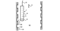
このような問題について図1Aおよび図1Bを参照してより詳しく記載される。図1Aは、円筒状中空エンクロージャ90の、本発明によらない検査を図式的に示す。これは、付けられるべきコーティングのグリップを改善する目的で機械的に処理された(活性化された)表面91を有する。このように、表面91はばち形横断面を有する隆起領域または突起92を有する。これらの隆起領域92は、表面91の底面に対してほぼ直角にではなくて、図示されているように角度を成して突出する。これらの突出する隆起領域92の寸法をなるべく正確に測定することが望ましい。図1Aは、センサユニット10を有する従来技術のセンサデバイス1を示す。これは、共焦点原理に従って作動し、従って測定方向11において正確に距離を測定することができる。測定方向11はセンサユニット10の外部光学系13により定められ、光はこの光学系13により測定方向11に放射され、測定方向11から来た光はさらにセンサデバイス1の光検出器の方へ案内される。この目的のために光は光ファイバ19を通してセンサユニット10の方へおよび/またはセンサユニット10から離れる方へ案内される。示されている従来技術センサデバイス1の場合、測定方向11はセンサユニット10の縦軸15に対して垂直である。さらに、測定方向11は運動方向31に対して垂直であり、この運動方向に沿ってセンサユニット10は中空エンクロージャ90の中へ移動させられる。図1Aから分かるであろうように、検査されるべき表面91に対して垂直な単一の測定方向11を用いるときには、突起92の突出領域の傾きおよび形状に関する情報を得ることはほとんど不可能である。
Such issues will be described in more detail with reference to FIGS. 1A and 1B. FIG. 1A schematically shows an inspection of the cylindrical
測定方向11が表面91に対して最早垂直でなく、従って隆起した突起91の陰を見ることもできるようにセンサユニット10を傾けることが考えられる。そのような状況が図1Bに図式的に示されている。しかし、センサユニット10をそのように傾けたときには、外部光学系13の反対側端部を形成する細長いセンサユニット10の1つの端部(図1Bにおいてはセンサユニット10の上端)が表面91にぶつかってしまうであろうから、外部光学系13の検査されるべき表面91からの距離が大きくなる。共焦点距離センサは、実際、非常に高い測定分解能を有するけれども、その代わりに割合に小さい測定範囲しか有しない。図1Bの傾きの故に、外部光学系13の表面91からの距離はセンサユニット10の測定範囲を超える。この理由の故に、センサユニット10は、図示の位置では意味のある測定を実行できない。
It is conceivable to tilt the
この問題は、本発明のセンサデバイスにより克服される。本発明によれば、単一のセンサユニットで既に十分であり得る。しかし、この場合、測定方向はセンサユニットの縦軸に垂直でなくてもよい。実際には、測定方向はセンサユニットの縦軸に対して100°と250°の間の角度を形成する。この場合、この角度は、外部光学系からセンサユニットの中心領域の方へ延びる縦軸に対して外部光学系において測られる。従って、180°の角度は、測定方向が外部光学系からセンサの中心からまっすぐ離れる方へ延びることを意味する。一方、0°の角度は、測定方向が外部光学系からセンサユニット内へ、センサユニットの中心領域の方へ、延びるということを意味する。測定方向とセンサユニットの縦軸との間の前述の傾きの故に、センサユニットは、表面との衝突が起きたり共焦点センサユニットの測定範囲の外へ出たりすることなく、円筒状中空エンクロージャの表面上の突起を2つの異なる回転位置で調べることができるということが達成される。 This problem is overcome by the sensor device of the present invention. According to the present invention, a single sensor unit may already be sufficient. However, in this case, the measurement direction does not have to be perpendicular to the vertical axis of the sensor unit. In practice, the measurement direction forms an angle between 100 ° and 250 ° with respect to the vertical axis of the sensor unit. In this case, this angle is measured in the external optical system with respect to the vertical axis extending from the external optical system toward the central region of the sensor unit. Therefore, an angle of 180 ° means that the measurement direction extends straight away from the center of the sensor from the external optics. On the other hand, an angle of 0 ° means that the measurement direction extends from the external optical system into the sensor unit and toward the central region of the sensor unit. Due to the aforementioned tilt between the measurement direction and the vertical axis of the sensor unit, the sensor unit is a cylindrical hollow enclosure without collision with the surface or out of the measurement range of the confocal sensor unit. It is achieved that the protrusions on the surface can be examined at two different rotational positions.
本発明によれば、測定方向の異なる少なくとも2つのセンサユニットが存在することも規定され得る。特に、円筒状中空エンクロージャの表面の突出する隆起領域を効果的に測定するためにセンサユニットの傾斜または回転を必要としないように、2つの測定方向を選択することが可能である。この場合、運動方向に対する測定方向のためのデフォルト角度を、2つのセンサユニットが検査されるべき中空エンクロージャに出入りできるように、定めることができる。作動時に検査されるべき円筒状中空エンクロージャはその縦軸が運動方向とちょうど一致するように有利に配置されるので、運動方向は重要な基準値である。このことは、1つまたは複数のセンサユニットが円筒状中空エンクロージャの全ての高さにおいて同等の結果を提供することができるとともに共焦点距離測定の限られた測定範囲が常に順守されるということを保証する。 According to the present invention, it may be specified that there are at least two sensor units having different measurement directions. In particular, it is possible to choose between two measurement directions so that tilting or rotation of the sensor unit is not required to effectively measure the protruding raised areas on the surface of the cylindrical hollow enclosure. In this case, a default angle for the measurement direction with respect to the direction of motion can be defined so that the two sensor units can enter and exit the hollow enclosure to be inspected. The direction of motion is an important reference because the cylindrical hollow enclosure to be inspected during operation is advantageously positioned so that its vertical axis exactly coincides with the direction of motion. This means that one or more sensor units can provide equivalent results at all heights of the cylindrical hollow enclosure and that the limited measurement range of confocal length measurements is always adhered to. Guarantee.
共焦点距離測定は、一般に、センサユニットが光学系、例えば凸レンズ、全体として正の屈折力を有するレンズ群または光収束効果を有するミラーなどの反射手段を有し、この光学系により、検査されるべき表面の方へ放射されるべき光が放出されかつ検査されるべき表面から戻ってきた光が光検出器の方へ通されるという風に定義され得る。有利なことに、このことにより照明焦点は検出焦点とちょうど一致する。共焦点光学系とも称され得る前述の光学系と光検出器との間において、中間平面にピンホールを配置することもできる。このピンホールは、光検出器が実質的に照明焦点の領域からくる光だけを受け取れるように、焦点外れ光を遮断する。ピンホールの代わりに光ファイバを中間平面に配置することも可能であり、この光ファイバは光の伝導に関してピンホールと同様の効果を有する。光源と共焦点光学系との間において、ピンホールを中間平面に配置することも可能である。ピンホールの代わりにまたはピンホールに加えて、光源の光を伝導する光導波管を使用することが可能である。この場合、この光導波管の、外部光学系の方に向いている端部は中間平面に配置される。この共焦点動作モードにより、特別に高い測定分解能が達成される。この分解能は、例えば三角測量測定方法に従って動作する他の光学式距離測定デバイスの分解能より良好である。 Cofocal length measurement is generally inspected by a sensor unit having an optical system, such as a convex lens, a lens group having positive refractive power as a whole, or a mirror having a light converging effect. It can be defined as the light emitted towards the surface to be emitted and the light returning from the surface to be inspected being passed towards the light detector. Advantageously, this causes the illumination focus to exactly coincide with the detection focus. Pinholes can also be placed in an intermediate plane between the photodetector and the aforementioned optical system, which can also be referred to as a confocal optical system. This pinhole blocks out-of-focus light so that the photodetector can receive virtually only light coming from the area of illumination focus. It is also possible to arrange the optical fiber in the intermediate plane instead of the pinhole, and this optical fiber has the same effect as the pinhole in terms of light conduction. It is also possible to arrange pinholes in an intermediate plane between the light source and the confocal optical system. It is possible to use an optical waveguide that conducts the light of the light source instead of or in addition to the pinhole. In this case, the end of the optical waveguide facing the external optical system is arranged in an intermediate plane. This confocal mode of operation achieves exceptionally high measurement resolution. This resolution is better than, for example, the resolution of other optical distance measuring devices operating according to the triangulation measuring method.
検査されるべき光が共焦点光学系から光源の方へではなくて光検出器の方へ進むようにするために、ビームスプリッタを利用できると有利である。このビームスプリッタは、検査されるべき光を少なくとも部分的に共焦点光学系から光検出器へ進ませ、照明光を少なくとも部分的に光源から共焦点システムへ進ませる。ビームスプリッタとして、例えば部分的透過ミラー、偏光ビームスプリッタ、または波長に応じて光を伝導するかまたは反射するカラースプリッタを使用することが可能である。 It would be advantageous to have a beam splitter to allow the light to be inspected to travel from the confocal optics towards the photodetector rather than towards the light source. The beam splitter directs the light to be inspected at least partially from the confocal optical system to the photodetector and at least partially from the light source to the confocal system. As the beam splitter, for example, a partially transmissive mirror, a polarizing beam splitter, or a color splitter that conducts or reflects light depending on the wavelength can be used.
共焦点光学系は、基本的に外部光学系と同一であってもよいけれども、好ましくは外部光学系とは異なる。このように、外部光学系を所望のタスクにより簡単な方法で適合またはそのタスクのために交換することが可能である。このように、外部光学系が測定方向を決定し、この測定方向において光が放射されかつ受け取られる。外部光学系は理論上任意の光学素子、例えば屈折素子、光回折素子または光反射素子など、であってよく、または前述の素子のうちの1つまたは複数を含むことができる。 The confocal optical system may be basically the same as the external optical system, but is preferably different from the external optical system. In this way, the external optics can be adapted to the desired task in a simple way or replaced for that task. In this way, the external optical system determines the measurement direction, and light is emitted and received in this measurement direction. The external optical system may be theoretically any optical element, such as a refracting element, a light diffracting element or a light reflecting element, or may include one or more of the above-mentioned elements.
測定方向は、外部光学系から光が放射されるビーム経路の軸を指示することができる。普通、光は円錐の形状を成して放射され、その円錐形状は測定方向の開口角を形成し、測定方向はその円錐の中心を通る。従って測定方向の光の放射は、測定方向を囲む円錐の形で光が放射されることを意味すると理解されてもよい。測定方向に沿って外部光学系から一定の距離のところに、光ビームの最小横断面の焦点が生じ、この焦点は、特に、焦点光学系により定められ得る。 The measurement direction can indicate the axis of the beam path in which light is emitted from the external optical system. Normally, light is emitted in the shape of a cone, which forms an aperture angle in the direction of measurement, and the direction of measurement passes through the center of the cone. Therefore, the emission of light in the measurement direction may be understood to mean that the light is emitted in the form of a cone surrounding the measurement direction. At a certain distance from the external optics along the measurement direction, the focal point of the smallest cross section of the light beam occurs, which can be determined in particular by the focal optics.
各センサユニットのために光源と少なくとも1つの光検出器とがそれぞれに設けられ得る。光源と光検出器とはセンサユニットの細長い本体の中に収容され得る。代わりに、光源と光検出器とはセンサユニットの前記の細長い本体の外に配置される。さらに、光導波管により、光源からの光を細長い本体の方へ伝導し、そこから共焦点光学系を介して外部光学系へ伝導することが可能である。逆方向に、検査されるべき光は、外部光学系を介して共焦点光学系へ、さらに1つまたは複数の光導波管を介して光検出器へ伝導され得る。 A light source and at least one photodetector may be provided for each sensor unit. The light source and photodetector may be housed in an elongated body of the sensor unit. Instead, the light source and photodetector are located outside the elongated body of the sensor unit. Further, the optical waveguide makes it possible to conduct the light from the light source toward the elongated main body and from there to the external optical system via the confocal optical system. In the opposite direction, the light to be inspected can be conducted to the confocal optics via the external optics and further to the photodetector via one or more optical waveguides.
共焦点測定の場合、放射された光は円筒状中空エンクロージャの表面の1つの領域を照らす。照らされた領域から後方散乱された光、特に拡散されおよび/または反射された光、が光検出器により測定される。この光検出器は空間的分解を持っていなくてもよい。従って、光検出器は、カメラでなくてもよくて、特に、単一の感光素子から成っていてもよい。従って、1つの照らされる領域についてその受光素子の数に応じて無数の測定値を生成する空間分解光検出器を有する広範囲照明とは違って、照らされる領域について正確に1つの測定値が生成される。そのような広範囲照明と比べて、本発明により使用される共焦点測定は特に距離情報に関して、明らかにより高い精度を提供する。 For confocal measurements, the emitted light illuminates an area of the surface of the cylindrical hollow enclosure. Light backscattered from the illuminated area, especially diffused and / or reflected light, is measured by a photodetector. This photodetector does not have to have spatial decomposition. Therefore, the photodetector does not have to be a camera, and may in particular consist of a single photosensitive element. Therefore, unlike wide-area illumination with a spatially resolved photodetector that produces innumerable measurements for an illuminated area depending on the number of light receiving elements, exactly one measurement is generated for the illuminated area. To. Compared to such wide range illumination, the confocal measurements used by the present invention provide significantly higher accuracy, especially with respect to distance information.
このように、センサユニットの細長い形状は、前記センサユニットのハウジングまたは外部寸法がそれに直角な方向における寸法の少なくとも2倍または3倍であることを意味すると理解されてよい。縦軸は、その細長い形状に沿って延びる軸と、すなわち、特に、センサユニットが自身の最大寸法を有する方向に延びる軸と、定義される。細長い形状の端面は特に一方の側では外部光学系により、反対側では1つまたは複数の光ファイバのための接続手段により、確定され得る。 Thus, the elongated shape of the sensor unit may be understood to mean that the housing or external dimensions of the sensor unit are at least two or three times the dimensions in the direction perpendicular to it. The vertical axis is defined as an axis that extends along its elongated shape, that is, in particular, an axis that extends in the direction in which the sensor unit has its own maximum dimensions. The elongated shaped end face can be determined, especially by external optics on one side and by connecting means for one or more optical fibers on the other side.
少なくとも1つのセンサユニットを測定位置へ移動させるために、運動メカニズムが使用される。この運動メカニズムは、少なくとも1つのセンサユニットが一定の、特に直線的な、運動方向において動くことができる限り、任意の所望の仕方で設計されてよい。この運動方向は、検査されるべき円筒状中空エンクロージャの縦軸と一致してもよい。運動メカニズムは、適宜に、少なくとも1つのセンサユニットをさらに前記運動方向に対して横向きまたは垂直な方向にも移動させるように設計されてもよい。このことは、最初に、少なくとも1つのセンサユニットを検査されるべき円筒状中空エンクロージャの上に位置させ、その後、少なくとも1つのセンサユニットを前記円筒状中空エンクロージャの中に入る運動方向に移動させるために、望ましいであろう。好都合なことには、この目的のために運動メカニズムは、少なくとも1つの駆動装置、例えばモータ、磁気リニア駆動装置または他の設定装置を含む。 A motion mechanism is used to move at least one sensor unit to the measurement position. This motion mechanism may be designed in any desired manner as long as at least one sensor unit can move in a constant, particularly linear, motion direction. This direction of motion may coincide with the vertical axis of the cylindrical hollow enclosure to be inspected. The motion mechanism may be appropriately designed to move at least one sensor unit in a lateral or perpendicular direction to the motion direction. This is because at least one sensor unit is first positioned above the cylindrical hollow enclosure to be inspected and then at least one sensor unit is moved in the direction of motion into the cylindrical hollow enclosure. Would be desirable. Conveniently, for this purpose the motion mechanism includes at least one drive device, such as a motor, a magnetic linear drive device or another set device.
本発明によるセンサデバイスの好ましい実施形態の場合、第1センサユニット、特にその外部光学系、はその測定方向がその縦軸に対して20°と85°、特に30°と80°、の角度を成すように設計される。さらに、第2センサユニット、特にその外部光学系、はその測定方向がその縦軸に対して95°と160°、特に100°と150°の間の角度を成すように設計され得る。 In the preferred embodiment of the sensor device according to the present invention, the first sensor unit, particularly its external optical system, has its measurement direction at an angle of 20 ° and 85 °, particularly 30 ° and 80 ° with respect to its vertical axis. Designed to do. Further, the second sensor unit, particularly its external optics, may be designed so that its measurement direction makes an angle between 95 ° and 160 °, particularly 100 ° and 150 ° with respect to its vertical axis.
センサユニットの外部光学系は、縦方向において、属するセンサユニットの端部領域に有利に配置され得る。本明細書全体を通じ、角度仕様は、縦方向に対して0°の角度では測定方向がセンサユニットの中の方をまっすぐ指し、180°の角度では縦方向においてセンサユニットから出る方をまっすぐ指すことを意味すると理解され得る。自身の縦軸に対する測定方向が別様に形成される2つのセンサユニットにより、シリンダの、特に内燃機関向けに製造されるシリンダの表面壁上の隆起領域を特別に良く調べることが可能である。さらに、前述の角度範囲により、検査されるべき中空エンクロージャ内へのセンサユニットの挿入時にセンサユニットの縦寸法は邪魔にならないかまたはほとんど邪魔にならないということが達成される。 The external optics of the sensor unit may be advantageously located in the end region of the sensor unit to which it belongs in the vertical direction. Throughout this specification, the angle specification refers to the measurement direction pointing straight toward the inside of the sensor unit at an angle of 0 ° with respect to the vertical direction, and pointing straight out of the sensor unit at an angle of 180 ° in the vertical direction. Can be understood to mean. The two sensor units, which have different measurement directions with respect to their own vertical axis, allow a particularly good examination of the raised area on the surface wall of the cylinder, especially those manufactured for internal combustion engines. Further, the above-mentioned angular range achieves that the vertical dimension of the sensor unit is unobtrusive or almost unobtrusive when the sensor unit is inserted into the hollow enclosure to be inspected.
さらに、第1センサユニットおよび第2センサユニットの縦軸を互いに実質的に平行に配置するとともにそれらの縦軸を運動方向に実質的に平行に向けると規定することも可能である。「実質的に平行」という表現は最大15°までまたは好ましくは最大5°までの角度であり得る。センサユニットを互いに平行にかつ運動方向に平行に向ければ、検査されるべき中空エンクロージャの横断面に関して必要とされるスペースは特に小さい。このことは、センサデバイスが、同様に円筒状中空エンクロージャの中へ移動させられるべき別のセンサを利用可能としなければならない場合、有利である。 Further, it is also possible to specify that the vertical axes of the first sensor unit and the second sensor unit are arranged substantially parallel to each other and their vertical axes are oriented substantially parallel to the direction of motion. The expression "substantially parallel" can be at angles up to 15 ° or preferably up to 5 °. If the sensor units are oriented parallel to each other and parallel to the direction of motion, the space required for the cross section of the hollow enclosure to be inspected is particularly small. This is advantageous if the sensor device must also have available another sensor that should be moved into the cylindrical hollow enclosure.
1つの好ましい実施形態の場合、第1センサユニットおよび第2センサユニットは同一の形状を持っていて、一方が他方に関して回転しているように配置される。この場合、特に、2つのセンサユニットは、自身の回転角度を除いて同一であり得る。このことは、製造を簡略化する。センサユニット間のそのような回転は、前述の運動方向に対して横向きにまたは垂直に(従って検査されるべき中空シリンダの縦軸に対して横向きにまたは垂直に)位置する軸に関しての角度であり得る。 In one preferred embodiment, the first sensor unit and the second sensor unit have the same shape and are arranged such that one is rotating with respect to the other. In this case, in particular, the two sensor units can be the same except for their own rotation angle. This simplifies manufacturing. Such rotation between sensor units is an angle with respect to an axis located laterally or perpendicular to the aforementioned direction of motion (and thus laterally or perpendicular to the vertical axis of the hollow cylinder to be inspected). obtain.
他の1つの好ましい実施形態においては、各センサユニットは、そのセンサユニットのベースフレームに自身を取り付けるための機械的連結手段を有する上部構造を含み、その上部構造はそのセンサユニットの外部光学系を収容する。従って、異なる測定方向を実現する目的のために、その他の点では同一のセンサユニット上に異なる上部構造を用いれば十分である。さらに、使用法に応じて異なる上部構造を有する同一のセンサユニットを設けることも可能である。上部構造は、機械的係留手段として例えばネジを有することができ、または、プレス嵌めによってベースフレームに保持されるように形成されてもよい。ベースフレームは、特に、センサユニットの、共焦点イメージのために必要な光学素子が収容される部分と見なされてよく、上部構造の中の外部光学系は単にビーム転向を生じさせるに過ぎない。 In another preferred embodiment, each sensor unit comprises a superstructure having mechanical coupling means for attaching itself to the base frame of the sensor unit, the superstructure comprising the external optics of the sensor unit. Accommodate. Therefore, it is sufficient to use different superstructures on the same sensor unit otherwise for the purpose of achieving different measurement directions. Further, it is possible to provide the same sensor unit having a different superstructure depending on the usage. The superstructure can have screws, for example, as mechanical mooring means, or may be formed to be held to the base frame by press fitting. The base frame may be considered, in particular, the part of the sensor unit that houses the optics needed for the confocal image, and the external optics in the superstructure merely give rise to beam diversion.
好ましくは、第1センサユニットの上部構造と第2センサユニットの上部構造とは測定方向において異なり、測定方向は、それぞれの外部光学系によってそれぞれのセンサユニットのベースフレームの中の光路に対して定められる。例えば、2つの上部構造の外部光学系を、別様に傾いたミラー面により形成することが可能である。それらの異なる上部構造は、自身の外部光学系を別として、同一であってよいであろう。 Preferably, the superstructure of the first sensor unit and the superstructure of the second sensor unit are different in the measurement direction, and the measurement direction is determined by each external optical system with respect to the optical path in the base frame of each sensor unit. Be done. For example, two superstructure external optics can be formed by differently tilted mirror surfaces. Their different superstructures may be identical, apart from their own external optics.
第1センサユニットの測定方向と第2センサユニットの測定方向とは、好ましくは、互いに対して15°から60°の角度、特に18°と45°の間の角度を形成する。この場合、その角度を1つの平面において定義することが可能であり、その角度は運動方向と第1センサユニットの測定方向とにより決定される。もし第2センサユニットの測定方向がこの平面内に存在しなければ、角度仕様を決定するためにこの測定方向の前記平面への射影が使用される。このようにして、センサユニット同士の間の測定方向の周りの回転角度は無視されたままである。 The measurement direction of the first sensor unit and the measurement direction of the second sensor unit preferably form an angle of 15 ° to 60 ° with respect to each other, particularly an angle between 18 ° and 45 °. In this case, the angle can be defined in one plane, which is determined by the direction of motion and the measurement direction of the first sensor unit. If the measurement direction of the second sensor unit is not in this plane, the projection of this measurement direction onto the plane is used to determine the angle specification. In this way, the rotation angle between the sensor units in the measurement direction remains neglected.
他の1つの好ましい実施形態においては、モータ付きデバイスが設けられ、ピボット軸受により取り付けられているセンサユニットを第1距離測定および第2距離測定のために異なる回転位置へ回転させるように調整される。便利なことに、この場合には、センサユニットが回転可能に取り付けられているホルダを設けることが可能であり、運動メカニズムを介して特に直線的に、検査されるべき中空シリンダの中へ移動させることができ、その後でモータ付きデバイスは検査されるべき中空エンクロージャの中でセンサユニットを回転させることができる。従って、第1距離測定および第2距離測定を正確に実行するために、簡潔な仕方で単一のセンサユニットで十分であり得る。 In another preferred embodiment, a motorized device is provided and the sensor unit mounted by the pivot bearing is tuned to rotate to different rotational positions for the first and second distance measurements. .. Conveniently, in this case it is possible to provide a holder in which the sensor unit is rotatably mounted and moved through a motion mechanism, especially linearly, into the hollow cylinder to be inspected. The motorized device can then rotate the sensor unit in a hollow enclosure to be inspected. Therefore, a single sensor unit may be sufficient in a concise manner to accurately perform the first and second distance measurements.
第1距離測定および第2距離測定は、本明細書において測定方向が互いに異なる。円筒状中空エンクロージャをその高さにわたって調べるために、異なる高さで複数の第1距離測定を実行するべく運動方向における1つまたは複数のセンサユニットの運動を提供することが可能である。複数の第2距離測定を実行することも同様に可能である。特に、第1距離測定および第2距離測定は、その目的のために異なるセンサユニットが使用されるとき、同時に行われ得る。この場合、第1距離測定の高さ位置は、同時に行われる第2距離測定の高さ位置と異なり得る。 The first distance measurement and the second distance measurement have different measurement directions in the present specification. It is possible to provide the motion of one or more sensor units in the direction of motion to perform multiple first distance measurements at different heights to examine the cylindrical hollow enclosure over its height. It is also possible to perform a plurality of second distance measurements. In particular, the first distance measurement and the second distance measurement can be performed simultaneously when different sensor units are used for that purpose. In this case, the height position of the first distance measurement may be different from the height position of the second distance measurement performed at the same time.
従って、
− 少なくとも1つのセンサユニットを運動メカニズムによって円筒状中空エンクロージャ内で様々な高さ位置へ移動させ、
− 様々な高さ位置で複数の第1距離測定を実行するとともに様々な高さ位置で複数の第2距離測定を実行し(その場合、第1距離測定の高さ位置は第2距離測定の高さ位置と同一であってもよく、異なってもよい)、
− 複数の第1距離測定の測定結果を用い、関連する高さ位置を考慮して、円筒状中空エンクロージャの表面の隆起領域の幾何学的寸法を計算し、
− 複数の第2距離測定の測定結果を用い、関連する高さ位置を考慮して、円筒状中空エンクロージャの表面の隆起領域の幾何学的寸法を計算する、
ように制御手段を構成することが可能である。
Therefore,
-At least one sensor unit is moved to various height positions in a cylindrical hollow enclosure by a motion mechanism.
-Perform multiple first distance measurements at various height positions and perform multiple second distance measurements at various height positions (in which case the height position of the first distance measurement is that of the second distance measurement. It may be the same as or different from the height position),
-Using the measurement results of multiple first distance measurements, and taking into account the relevant height positions, calculate the geometric dimensions of the raised area on the surface of the cylindrical hollow enclosure.
-Calculate the geometric dimensions of the raised area on the surface of the cylindrical hollow enclosure, taking into account the relevant height positions, using the results of multiple second distance measurements.
It is possible to configure the control means as such.
計算される幾何学的寸法は、特に、隆起領域の運動方向におけるオーバーハングおよび/または隆起領域が突出する角度に関連し得る。第1距離測定により、特に、センサユニットの円筒状中空エンクロージャの中への挿入の方向における隆起領域のオーバーハングを調べることが可能である。一方、第2距離測定により、特に、センサユニットの引き出しの方向における隆起領域のオーバーハングを調べることが可能である。 The calculated geometric dimensions may be particularly related to the overhang and / or the angle at which the ridge region protrudes in the direction of motion of the ridge region. The first distance measurement makes it possible to examine the overhang of the raised region, especially in the direction of insertion of the sensor unit into the cylindrical hollow enclosure. On the other hand, the second distance measurement makes it possible to investigate the overhang of the raised region, in particular, in the direction of pulling out the sensor unit.
一般に、運動メカニズムに対して横向きのまたは垂直な方向において2つのセンサユニットの動揺または振動が生じることがある。そのような振動により、センサユニットの中空エンクロージャからの距離が変化するであろう。従って距離測定はそのような振動から悪い影響を被る。この理由から、そのような振動は少なくとも1つの第3センサユニットにより検出される。そのとき、第1センサユニットおよび第2センサユニットの距離測定データを、確認された振動に応じて訂正することができる。従って、「少なくとも1つの第3センサユニット」という表現は、第1センサユニットおよび第2センサユニットに加えて1つまたは複数のさらなるセンサユニットが設けられることを意味すると理解されるべきである。この1つまたはこれらのさらなるものは光学共焦点距離測定のためにセットされる。少なくとも1つの第3センサユニットの測定方向は、第1距離測定および第2距離測定の測定方向に対して運動方向に垂直の平面の中で45°と315°の間の角度を成して配置され得る。制御手段は、今、運動方向に垂直の平面内で動作する少なくとも1つの第3センサユニットの距離測定データの助けにより第1センサユニットおよび任意に第2センサユニットの位置の変動を分類するように構成される。好ましくは、任意のさらなる第3センサユニットは、第1距離測定および第2距離測定のために使用される測定方向に対して90°と270°の間の角度を成し、その角度は運動方向に垂直な平面において定義される。さらに、この平面から外への傾きの角度が存在してもよい。1つの第3センサおよび1つの第4センサユニットを使用することが特に好ましい。この場合、これらの2つのセンサユニットの測定方向は前記平面内で好ましくは同様に互いに対して90°から180°の角度を成す。より好ましくは、この角度は120°であり、さらに、これらの2つのセンサユニットの2つの測定方向はそれぞれ第1距離測定および第2距離測定の測定方向に対して120°の角度を形成する。第1距離測定および第2距離測定の測定方向は運動方向に垂直の平面内で互いに整列する、すなわち、それらは0°の角度を形成することができる。この整列は、本明細書に記載された残りの全ての実施形態の場合にも設けられ得る。 In general, the two sensor units may sway or vibrate in a lateral or perpendicular direction to the motion mechanism. Such vibrations will change the distance of the sensor unit from the hollow enclosure. Therefore distance measurements are adversely affected by such vibrations. For this reason, such vibrations are detected by at least one third sensor unit. At that time, the distance measurement data of the first sensor unit and the second sensor unit can be corrected according to the confirmed vibration. Thus, the expression "at least one third sensor unit" should be understood to mean that in addition to the first sensor body Contact good beauty second sensor unit is one or more additional sensor units are provided .. This one or an additional one of these is set for optical cofocal length measurement. The measurement direction of at least one third sensor unit is arranged at an angle between 45 ° and 315 ° in a plane perpendicular to the movement direction with respect to the measurement directions of the first distance measurement and the second distance measurement. Can be done. The control means now classifies the position variation of the first sensor unit and optionally the second sensor unit with the help of distance measurement data of at least one third sensor unit operating in a plane perpendicular to the direction of motion. It is composed. Preferably, any additional third sensor unit forms an angle between 90 ° and 270 ° with respect to the measurement directions used for the first and second distance measurements, which angle is the direction of motion. Defined in a plane perpendicular to. Further, there may be an angle of inclination from this plane to the outside. It is particularly preferred to use one third sensor and one fourth sensor unit. In this case, the measurement directions of these two sensor units preferably form an angle of 90 ° to 180 ° with respect to each other in the plane. More preferably, this angle is 120 °, and the two measurement directions of these two sensor units form an angle of 120 ° with respect to the measurement directions of the first distance measurement and the second distance measurement, respectively. The measurement directions of the first and second distance measurements are aligned with each other in a plane perpendicular to the direction of motion, i.e. they can form an angle of 0 °. This alignment can also be provided for all remaining embodiments described herein.
第3センサユニットと、場合によっては利用可能な他のセンサユニットとは、第1センサユニットおよび第2センサユニットと機械的に連結され、前記センサユニットと一緒に運動メカニズムにより移動させられる。従って、前記センサユニット間の距離は既知であり、特に固定され得る、すなわち不変であってよい。このことは、全センサユニットの1つの位置に対して少なくとも1つの第3センサユニットの距離測定データから推定し得るために重要である。従って、少なくとも1つの第3センサユニットは次々に円筒状中空エンクロージャまでの距離測定を実行し、そのときセンサユニットと円筒状中空エンクロージャとの間の振動に対して、このようにして得られた距離測定データにおける変動から推定することができる。これらの位置データの助けにより、第1センサユニットおよび/または第2センサユニットを通して得られた幾何学的情報を訂正することが可能である。少なくとも1つの第3センサユニットの測定方向は、正確に、運動方向に垂直な平面の中にあり得る。しかし、代わりに、少なくとも1つの第3センサユニットの1つまたは複数の測定方向は、第1センサユニットおよび/または第2センサユニットについて記載されたように、運動方向に垂直な平面から突出してもよい。その他の点では、少なくとも1つの第3センサユニットは、特に、第1センサユニットおよび/または第2センサユニットと全く同じに設計されてよい。 The third sensor unit and, in some cases, other available sensor units are mechanically coupled to the first sensor unit and the second sensor unit and moved together with the sensor unit by a motion mechanism. Therefore, the distance between the sensor units is known and may be particularly fixed, i.e. immutable. This is important because it can be estimated from the distance measurement data of at least one third sensor unit with respect to one position of all sensor units. Therefore, at least one third sensor unit performs distance measurements to the cylindrical hollow enclosure one after the other, and the distance thus obtained with respect to the vibration between the sensor unit and the cylindrical hollow enclosure at that time. It can be estimated from the fluctuation in the measurement data. With the help of these position data, it is possible to correct the geometric information obtained through the first sensor unit and / or the second sensor unit. The measurement direction of at least one third sensor unit can be exactly in a plane perpendicular to the direction of motion. However, instead, one or more measurement directions of at least one third sensor unit may project from a plane perpendicular to the direction of motion, as described for the first sensor unit and / or the second sensor unit. Good. In other respects, at least one third sensor unit may be specifically designed to be exactly the same as the first sensor unit and / or the second sensor unit.
本発明のセンサデバイスの様々な実施形態は、本発明による方法の有利な別形とも見なされ得る。 Various embodiments of the sensor device of the present invention can also be considered as advantageous variants of the method according to the invention.
特に、方法別形は、センサデバイスの意図された用途から生じる。 In particular, the method variants arise from the intended use of the sensor device.
本発明のさらなる利点および特徴は、以下で、添付の概略図を参照して記載される。 Further advantages and features of the present invention are described below with reference to the accompanying schematic.
同等のコンポーネントおよび同様に作用するコンポーネントは、普通、図面において同じ参照数字により示される。 Equivalent and similarly acting components are usually indicated by the same reference numerals in the drawings.
図1Aの従来技術のセンサデバイス1は上に記載されている。そこでセンサデバイス1のコンポーネントに関してなされた記載は、本発明によるセンサデバイスの実施形態の、同じ参照数字を伴うコンポーネントにも当てはまる。 The prior art sensor device 1 of FIG. 1A is described above. Therefore, the description made regarding the component of the sensor device 1 also applies to the component with the same reference number in the embodiment of the sensor device according to the present invention.
本発明のセンサデバイス100の第1の例示的実施形態を図2Aおよび図2Bを参照して記載する。図2Aは、検査されるべき中空エンクロージャ90の中へ移動させられたセンサデバイス100のコンポーネントを概略的に示す。図2Bは、図2Aのセンサデバイス100に対する一定の角度を示すのに役立つ。
A first exemplary embodiment of the
センサデバイス100は、共焦点距離測定を実行するようにそれぞれセットされている2つのセンサユニット10、20を含む。
The
この目的のために、センサデバイス100は、利用できる1つまたは複数の光源(図示されていない)を有し、その光は光導波管または光ファイバ19、29を介して2つのセンサユニット10、20へ伝導される。センサユニット10、20の各々は、放射された光の焦点を生じさせる共焦点光学系(例えば、1つのレンズまたはレンズ群)を含む。センサユニット10、20は、それぞれ、利用できる外部光学系13、23をさらに有し、これらの外部光学系は測定方向11、21を、すなわち共焦点光学系から来る光の放射方向を、定める。放射された光は、検査されるべき中空エンクロージャ90の表面91を照らす。これにより光は後方散乱および/または反射される。この反射された光は再び外部光学系13、23ならびにそれぞれの共焦点光学系を介してさらに光検出器(図示されていない)の方へ伝導される。例えば、後方散乱された光を光ファイバ19、29を介して光検出器へ伝導することが可能であり、それらの検出器は、検査されるべき中空エンクロージャ90の中へ移動させられない。
For this purpose, the
センサユニット10、20の各々が利用できる光検出器を有し、その光検出器がセンサユニット10または20の細長い本体に収容され、光源がセンサユニット10、20の外側に配置されて光ファイバ19、29を介してセンサユニット10、20と連結されると有利であろう。
Each of the
本記載の範囲内において、光ファイバ19、29は、特に、光源からの照明光と後方散乱された検査されるべき光とを互いに無関係に伝導することのできる複数のファイバを含む束を意味するとも理解され得る。
Within the scope of this description, the
図2Aにおいて、2つのセンサユニット10、20は1つの共通キャリアに取り付けられている。このキャリアは運動方向31に移動させられ得る。このようにして、センサユニット10、20を検査されるべき中空エンクロージャ90の中へ運動方向31に沿って移動させ、検査が行われた後に元通りにそこから引き出すことが可能である。これは、測定動作中、検査されるべき中空エンクロージャ90の外側に配置されている運動メカニズム(ここでは図示されていない)により行われる。有利なことに、運動方向31は、円筒状中空エンクロージャ90の縦軸または円筒軸とちょうど一致する。
In FIG. 2A, the two
本発明の本質的着想は、2つのセンサユニット10、20の測定方向11、21が測定動作時に中空エンクロージャ90の表面91に対して垂直ではなくて傾いているように向けられることにある。表面91の微細構造、すなわち表面91の窪みおよび/または隆起、は図において説明を目的として拡大された規模で示されている。「垂直」という句は、そのような微細構造と関連してではなくて、表面91のより大きな領域と関連して理解されるべきである。
The essential idea of the present invention is that the
2つの測定方向11、21は互いに15°と40°の間の、好ましくは18°と30°の間の角度を成す。この場合、その角度は、運動方向31を含み、その結果として円筒軸を含む平面において定義される。従って、測定方向11、21の円筒軸の周りの回転角度は重要でない。基本的に、記載されるすべての実施形態の場合において、そのような回転角度が形成されてもよい。
The two
図2Bを参照して、図2Aの測定方向11、21の向きをより詳しく説明する。センサユニット10は縦軸15を有し、これに対して測定方向11は角度12を成す。センサユニット20は縦軸25を有し、これに対して測定方向21は角度22を成す。示されている例では、角度12、22が一致するように2つのセンサユニット10、20を同一に設計することが可能である。しかし、2つのセンサユニット10、20は、互いに対して回転させられている。その結果として、それらの縦軸15、25は互いに平行ではなくて、運動方向31に対して異なる角度を形成する。この理由から、測定方向11は測定方向31に対して角度32を成し、この角度32は、測定方向21が運動方向31に対して成す角度33とは異なる。角度32は70°と85°の間にあってよく、角度33は95°と110°の間にあってよい。
The orientations of the
測定方向が角度32について述べられた角度範囲の中にあるならば、関連する距離測定も第1距離測定と称されるであろう。一方、もし測定方向が角度33について述べられた角度範囲の中にあれば、関連する距離測定は第2距離測定と称されるであろう。
If the measurement direction is within the angle range mentioned for
図2Aに示されているように、この整列により、表面91の突き出している突起92の後へ光を放射し、そこから後方散乱された光を受け取ることが可能である。これに反して、このことは、図1Aのように中空エンクロージャ90の表面に対して垂直な測定方向の場合には、不可能である。
As shown in FIG. 2A, this alignment allows light to be emitted behind the protruding
本発明によるセンサデバイス100のさらなる例示的実施形態が図3に概略的に示されている。このセンサデバイスは、図2Aに示されているセンサデバイスと殆ど完全に一致し、2つのセンサユニット10、20のそれぞれの外部光学系13、23において図2Aのセンサデバイスと異なる。図3において2つのセンサユニットは、異なる光偏向方向を生じさせる異なる外部光学系13、23を示す。そのため、図3においては、図2Bに関して説明したように測定方向11と縦軸15との間に形成される角度12は、測定方向21と縦軸25との間に形成される角度22とは異なる。一方、測定方向11、21と運動方向31との間に定義される角度32、33は、図2Bに関して記載された通りであり得る。従って、図3においては、測定方向11、12は検査されるべき表面91および運動方向31に対して異なる角度を成す。一方、2つの縦軸15、25は、特に、互いに平行におよび/または運動方向31に平行に配置されてよい。その結果として、運動方向31に垂直な平面における空間的要求は少ない。平行配置の代わりに、例えば最大20°の片寄りも可能であるが、その場合にも依然として前記平面における空間的要求は割合に少ない。
A further exemplary embodiment of the
示されている2つに加えてさらなるセンサユニットが存在してもよい。しかし、代わりに、単一のセンサユニット10により2つの前記測定方向11、21が順々に調整されることも可能である。このことは、その実施形態が図4Aおよび図4Bに2つの異なる調整で示されているセンサデバイス100のさらなる実施形態において当てはまる。
In addition to the two shown, there may be additional sensor units. However, instead, the two
センサデバイス100もセンサユニット10を含み、その外部光学系13は、このセンサユニット10の縦軸15に対して測定方向11を確定する。測定方向11と縦軸15との間の角度12は、この場合、90°より大きく、好ましくは100°と250°の間にある。
The
これに関して、このセンサユニット10は、測定方向が縦軸に対して垂直な図1Aの公知のセンサユニットと異なる。98°と110°の間の角度により、図4Aに示されているように、図1Bにおいてそうであるように外部光学系13と対向する細長いセンサユニット10の端部を検査されるべき表面90の方へ傾けることを必要とせずに、突き出している突起92の後ろを測定することが可能である。
In this regard, the
図4Aのセンサユニット10はここでは回転可能に取り付けられていて、回転軸は運動方向31に横向きにまたは垂直に配置される。このようにして、センサユニットを例えば図4Bに示されているように回転位置へ至らせることが可能である。この回転位置では第1距離測定が可能であり、これに対して図4Aの回転位置は第2距離測定を可能にする。従って、有利なことに、上で詳しく記載した2つの距離測定をたった1つのセンサユニット10により実行することが可能である。
The
ここに図示されたセンサユニット10、20の他に、センサデバイス100は、その測定方向が運動方向31に対して垂直な平面内で測定方向11、21と異なるさらなるセンサユニットを含むことが可能である。それらのさらなるセンサユニットは、センサユニット10、20の位置を制御するのに役立つ。従ってそれらのさらなるセンサユニットはそれぞれ円筒状中空エンクロージャまでの距離を測定し、これらの測定された距離の変動から全センサユニットの円筒状中空エンクロージャに対する振動に対して結論を下すことができる。センサユニット10、20の第1距離測定および第2距離測定の測定データを、前記振動についての知識を用いて修正することができる。
In addition to the
本発明によるセンサデバイス100により、中空エンクロージャの、特に円筒状中空エンクロージャの、一様でない表面に関する貴重な幾何学的情報を収集し得るということが有利に達成される。
The
Claims (10)
− 前記センサデバイスは、それぞれ光学的共焦点距離測定のために構成されている少なくとも2つのセンサユニット(10、20)を有し、
− 前記少なくとも2つのセンサユニット(10、20)は少なくとも1つの第1センサユニット(10)および少なくとも1つの第2センサユニット(20)を含み、
− 前記少なくとも2つのセンサユニット(10、20)はそれぞれ光源および光検出器、または光導波管を有し、
− 前記少なくとも2つのセンサユニット(10、20)はそれぞれ細長い形状を有しかつ外部光学系(13、23)を含み、それらを通してそれぞれ、光が照射されるとともに受け取られ得る測定方向(11、21)はそれぞれのセンサユニット(10、20)の縦軸に対して横向きであり、
− 前記センサデバイスは運動メカニズムを有し、前記運動メカニズムは、前記少なくとも2つのセンサユニット(10、20)を1つの運動方向(31)において、検査されるべき円筒状中空エンクロージャ(90)の中へおよび前記円筒状中空エンクロージャの外へ、移動させるように構成される、
前記センサデバイスであって、
− 前記円筒状中空エンクロージャ(90)の表面の隆起を測定するための制御手段が設けられ、前記制御手段は、第1距離測定を実行するために前記第1センサユニット(10)を制御するように構成され、その第1距離測定の間、前記測定方向(11)は前記運動方向(31)に対して20°から85°の角度(32)を成し、前記制御手段は第2距離測定を実行するために前記第2センサユニット(20)を制御するように構成され、その第2距離測定の間、前記測定方向(21)は前記運動方向(31)に対して95°から160°の角度(33)を成し、
− 前記第1センサユニット(10)は、自身の測定方向(11)が前記運動方向(31)に対して20°から85°の角度(32)を成すように形成されかつ前記運動メカニズムと連結され、
− 前記第2センサユニット(20)は、自身の測定方向(21)が前記運動方向(31)に対して95°から160°の角度(33)を成すように形成されかつ前記運動メカニズムと連結され、
光学的共焦点距離測定のために構成されている少なくとも1つの第3センサユニットが設けられ、
前記少なくとも1つの第3センサユニットの測定方向は、前記第1距離測定および前記第2距離測定の前記測定方向(11、21)に対して、前記運動方向(31)に垂直な平面内で45°と315°の間の角度を形成し、
前記制御手段は、前記少なくとも1つの第3センサユニットの距離測定データの助けにより、前記運動方向(31)に垂直な平面内での前記第1センサユニットおよび第2センサユニット(10、20)の位置の変動を判定するように構成されている、
ことを特徴とする、センサデバイス。 A sensor device that inspects the surface of a cylindrical hollow enclosure (90).
-The sensor device has at least two sensor units (10, 20), each configured for optical cofocal length measurement.
-The at least two sensor units (10, 20) include at least one first sensor unit (10) and at least one second sensor unit (20).
-The at least two sensor units (10, 20) each have a light source and a photodetector, or an optical waveguide.
-The at least two sensor units (10, 20) each have an elongated shape and include external optics (13, 23), through which measurement directions (11, 21) that can be received and irradiated with light, respectively. ) Is horizontal with respect to the vertical axis of each sensor unit (10, 20).
-The sensor device has a motion mechanism, the motion mechanism in which the at least two sensor units (10, 20) are inspected in a cylindrical hollow enclosure (90) in one direction of motion (31). Configured to move to and out of the cylindrical hollow enclosure,
The sensor device
-A control means for measuring the surface ridge of the cylindrical hollow enclosure (90) is provided so that the control means controls the first sensor unit (10) to perform a first distance measurement. During the first distance measurement, the measurement direction (11) forms an angle (32) of 20 ° to 85 ° with respect to the movement direction (31), and the control means measures the second distance. The second sensor unit (20) is configured to control the second sensor unit (20), and during the second distance measurement, the measurement direction (21) is 95 ° to 160 ° with respect to the motion direction (31). Make an angle (33) of
− The first sensor unit (10) is formed so that its own measurement direction (11) forms an angle (32) of 20 ° to 85 ° with respect to the movement direction (31) and is connected to the movement mechanism. Being done
-The second sensor unit (20) is formed so that its own measurement direction (21) forms an angle (33) of 95 ° to 160 ° with respect to the movement direction (31) and is connected to the movement mechanism. Being done
At least one third sensor unit configured for optical cofocal length measurement is provided.
The measurement direction of the at least one third sensor unit is 45 in a plane perpendicular to the movement direction (31) with respect to the measurement directions (11, 21) of the first distance measurement and the second distance measurement. Form an angle between ° and 315 °,
Said control means, said at least one with the aid of the distance measurement data of the third sensor unit, wherein in a plane perpendicular to the direction of motion (31) the first sensor unit and second sensor unit (10, 20 ) Is configured to determine the change in position,
A sensor device characterized by that.
前記第2センサユニット(20)は自身の測定方向(11、21)が自身の縦軸に対して95°から160°の角度を成すように形成される、
ことを特徴とする、請求項1に記載のセンサデバイス。 The first sensor unit (10) is formed so that its own measurement direction (11, 21) forms an angle of 20 ° to 85 ° with respect to its own vertical axis.
The second sensor unit (20) is formed so that its own measurement direction (11, 21) forms an angle of 95 ° to 160 ° with respect to its vertical axis.
The sensor device according to claim 1.
前記上部構造は前記センサユニット(10、20)の前記外部光学系(13、23)を含む、
ことを特徴とする、請求項1〜4のいずれか一項に記載のセンサデバイス。 Each sensor unit (10, 20) has a superstructure as well as mechanical connecting means for attaching the superstructure to the base element of the sensor unit (10, 20).
The superstructure includes the external optics (13, 23) of the sensor unit (10, 20).
The sensor device according to any one of claims 1 to 4, wherein the sensor device is characterized in that.
− 前記運動メカニズムにより、前記少なくとも2つのセンサユニット(10、20)を前記円筒状中空エンクロージャ(90)内の様々な高さ位置へ移動させ、
− 様々な高さ位置での複数の第1距離測定と様々な高さ位置での複数の第2距離測定とを実行し、
− 複数の第1距離測定の測定結果を用いるとともに、関連する高さ位置を考慮して、前記円筒状中空エンクロージャ(90)の前記表面の隆起の幾何学的寸法を計算し、
− 複数の第2距離測定の測定結果を用いるとともに、関連する高さ位置を考慮して、前記円筒状中空エンクロージャ(90)の前記表面の隆起の幾何学的寸法を計算する、
ように構成されていることを特徴とする、請求項1〜8のいずれか一項に記載のセンサデバイス。 The control means further
-The motion mechanism moves the at least two sensor units (10, 20) to various height positions within the cylindrical hollow enclosure (90).
-Perform multiple first distance measurements at various height positions and multiple second distance measurements at various height positions,
-Using the measurement results of multiple first distance measurements and taking into account the relevant height positions, the geometric dimensions of the surface ridges of the cylindrical hollow enclosure (90) were calculated.
-Calculate the geometric dimensions of the surface ridges of the cylindrical hollow enclosure (90) using the results of multiple second distance measurements and taking into account the relevant height positions.
The sensor device according to any one of claims 1 to 8, wherein the sensor device is configured as described above.
− 前記方法は、検査されるべき円筒状中空エンクロージャ(90)の中へ少なくとも2つのセンサユニット(10、20)を運動方向(31)に沿って移動させるステップを含み、
− 前記方法は、前記少なくとも2つのセンサユニット(10、20)の各々によって光学的共焦点距離測定を実行するステップであって、前記少なくとも2つのセンサユニットは、それぞれ、前記光学的共焦点距離測定のために、外部光学系(13、23)を介して測定方向(11、21)に光を放射するとともに前記測定方向(11、21)から光を受け取る、前記光学的共焦点距離測定を実行する前記ステップを含み、
− 前記少なくとも2つのセンサユニット(10、20)は少なくとも1つの第1センサユニット(10)および1つの第2センサユニット(20)を含み、それぞれ光源および光検出器、または光導波管を示し、
− 前記少なくとも2つのセンサユニット(10、20)は細長い形状を有し、前記それぞれの測定方向(11、21)はそれぞれの前記センサユニット(10、20)の縦軸に対して横向きに位置し、
− 前記方法は、前記少なくとも2つのセンサユニット(10、20)を前記運動方向(31)に沿って、前記検査されるべき円筒状中空エンクロージャ(90)の外へ移動させるステップを含む、
方法であって、それぞれの前記光学的共焦点距離測定の実行は、
− 前記円筒状中空エンクロージャ(90)の表面の隆起を測定するために前記第1センサユニット(10)によって第1距離測定を実行するステップであって、前記測定方向(11)は前記第1距離測定の間は前記運動方向(31)に対して20°から85°の角度(32)を成している、前記第1距離測定を実行する前記ステップと、
− 前記円筒状中空エンクロージャ(90)の表面の前記隆起を測定するために前記第2センサユニット(20)によって第2距離測定を実行するステップであって、前記測定方向(21)は前記第2距離測定の間は前記運動方向(31)に対して95°から160°の角度(33)を成している、前記第2距離測定を実行する前記ステップと、
を含み、前記第1距離測定および前記第2距離測定に関して言及された前記角度は、
− 前記第1センサユニット(10)は、自身の測定方向(11)が前記運動方向(31)に対して20°から85°の角度(32)を成すように形成されて前記運動メカニズムと連結されるという事実と、
− 前記第2センサユニット(20)は、自身の測定方向(21)が前記運動方向(31)に対して95°から160°の角度(33)を成すように形成されて前記運動メカニズムと連結されるという事実と、
によって利用可能にされ、
− 光学的共焦点距離測定のために構成されている少なくとも1つの第3センサユニットが設けられ、
前記少なくとも1つの第3センサユニットの測定方向は、前記第1距離測定および前記第2距離測定の前記測定方向(11、21)に対して、前記運動方向(31)に垂直な平面内で45°と315°の間の角度を形成し、
前記制御手段は、前記少なくとも1つの第3センサユニットの距離測定データの助けにより、前記運動方向(31)に垂直な平面内での前記第1センサユニットおよび第2センサユニット(10、20)の位置の変動を判定するように構成されている、
ことを特徴とする、方法。 A method of inspecting the surface of a cylindrical hollow enclosure (90), at least
-The method comprises moving at least two sensor units (10, 20) along the direction of motion (31) into the cylindrical hollow enclosure (90) to be inspected.
-The method is a step of performing an optical cofocal length measurement by each of the at least two sensor units (10, 20), wherein the at least two sensor units each perform the optical cofocal length measurement. To perform the optical cofocal length measurement, which emits light in the measurement direction (11, 21) via an external optical system (13, 23) and receives light from the measurement direction (11, 21). Including the above steps
-The at least two sensor units (10, 20) include at least one first sensor unit (10) and one second sensor unit (20), indicating a light source and a photodetector, or an optical waveguide, respectively.
-The at least two sensor units (10, 20) have an elongated shape, and the respective measurement directions (11, 21) are located laterally with respect to the vertical axis of the respective sensor units (10, 20). ,
-The method comprises moving the at least two sensor units (10, 20) out of the cylindrical hollow enclosure (90) to be inspected along the direction of motion (31).
The method of performing each of the above optical cofocal length measurements is
-A step of performing a first distance measurement by the first sensor unit (10) to measure the surface ridge of the cylindrical hollow enclosure (90), wherein the measurement direction (11) is the first distance. The step of performing the first distance measurement, which forms an angle (32) of 20 ° to 85 ° with respect to the movement direction (31) during the measurement, and the step.
-A step of performing a second distance measurement by the second sensor unit (20) to measure the ridge on the surface of the cylindrical hollow enclosure (90), wherein the measurement direction (21) is the second. The step of performing the second distance measurement, which forms an angle (33) of 95 ° to 160 ° with respect to the movement direction (31) during the distance measurement, and the step.
The angles mentioned with respect to the first distance measurement and the second distance measurement include:
− The first sensor unit (10) is formed so that its own measurement direction (11) forms an angle (32) of 20 ° to 85 ° with respect to the movement direction (31) and is connected to the movement mechanism. The fact that it will be done
-The second sensor unit (20) is formed so that its own measurement direction (21) forms an angle (33) of 95 ° to 160 ° with respect to the movement direction (31) and is connected to the movement mechanism. The fact that it will be done
Made available by
− At least one third sensor unit configured for optical cofocal length measurement is provided.
The measurement direction of the at least one third sensor unit is 45 in a plane perpendicular to the movement direction (31) with respect to the measurement directions (11, 21) of the first distance measurement and the second distance measurement. Form an angle between ° and 315 °,
Said control means, said at least one with the aid of the distance measurement data of the third sensor unit, wherein in a plane perpendicular to the direction of motion (31) the first sensor unit and second sensor unit (10, 20 ) Is configured to determine the change in position,
A method characterized by that.
Applications Claiming Priority (3)
| Application Number | Priority Date | Filing Date | Title |
|---|---|---|---|
| EP15189812.9A EP3156760B1 (en) | 2015-10-14 | 2015-10-14 | Sensor device and method for surface inspection of a cylindrical cavity |
| EP15189812.9 | 2015-10-14 | ||
| PCT/EP2016/073844 WO2017063935A1 (en) | 2015-10-14 | 2016-10-06 | Sensor device and method for examining the surface of a cylindrical cavity |
Publications (2)
| Publication Number | Publication Date |
|---|---|
| JP2018535407A JP2018535407A (en) | 2018-11-29 |
| JP6840747B2 true JP6840747B2 (en) | 2021-03-10 |
Family
ID=54330626
Family Applications (1)
| Application Number | Title | Priority Date | Filing Date |
|---|---|---|---|
| JP2018519331A Active JP6840747B2 (en) | 2015-10-14 | 2016-10-06 | Sensor devices and methods for inspecting the surface of cylindrical hollow enclosures |
Country Status (11)
| Country | Link |
|---|---|
| US (1) | US10551176B2 (en) |
| EP (1) | EP3156760B1 (en) |
| JP (1) | JP6840747B2 (en) |
| KR (1) | KR102087758B1 (en) |
| CN (1) | CN108351198B (en) |
| ES (1) | ES2747305T3 (en) |
| HU (1) | HUE045623T2 (en) |
| PL (1) | PL3156760T3 (en) |
| PT (1) | PT3156760T (en) |
| SI (1) | SI3156760T1 (en) |
| WO (1) | WO2017063935A1 (en) |
Families Citing this family (5)
| Publication number | Priority date | Publication date | Assignee | Title |
|---|---|---|---|---|
| ES2663503T3 (en) * | 2015-01-20 | 2018-04-13 | Sturm Maschinen- & Anlagenbau Gmbh | Test installation and procedure for the analysis of a hollow body |
| CN111936822B (en) * | 2018-02-28 | 2022-08-23 | 德弗里茨自动化股份有限公司 | Trigger management device for a measurement apparatus |
| CN109631710A (en) * | 2019-01-08 | 2019-04-16 | 京东方科技集团股份有限公司 | Vernier caliper, distance measurement method and storage medium |
| CN110779449B (en) * | 2019-11-04 | 2021-03-19 | 辽宁工程技术大学 | Radial offset monitoring and alarming device for cylindrical equipment |
| CN111366102B (en) * | 2020-04-22 | 2022-07-26 | 山东省科学院激光研究所 | Refraction type color confocal measuring head structure for measuring surface appearance of inner hole |
Family Cites Families (12)
| Publication number | Priority date | Publication date | Assignee | Title |
|---|---|---|---|---|
| DE19714202A1 (en) * | 1997-04-07 | 1998-10-15 | Bosch Gmbh Robert | Device for the optical inspection of surfaces |
| DE19930688A1 (en) * | 1999-07-02 | 2001-01-04 | Byk Gardner Gmbh | Surface quality determination device for car bodywork, comprises illuminating device containing light emitting diode and device capturing light reflected from surface which contains photosensor, filter between them modifying light |
| EP1754018B1 (en) * | 2004-06-08 | 2018-07-11 | Micro-Epsilon Messtechnik GmbH & Co. KG | Device and method for inspecting the internal surfaces of holes |
| DE102005059550A1 (en) * | 2005-12-13 | 2007-06-14 | Siemens Ag | Optical measuring device for measuring inner wall of e.g. ear channel, in animal, has rotatable reflector rotatable around rotary axis so that inner wall of cavity is scanned along line circulating rotary axis |
| DE102005062130A1 (en) * | 2005-12-23 | 2007-06-28 | Isis Sentronics Gmbh | Scanning system includes sensor with transport module and bearing section as well as device for mounting the module |
| DE202008017935U1 (en) * | 2008-10-07 | 2010-12-30 | Fionec Gmbh | Optical probe (II) |
| CN101382422A (en) * | 2008-10-16 | 2009-03-11 | 上海交通大学 | Internal contour outline automatic detection system for pipe-shaped parts |
| DE102012204498A1 (en) * | 2012-03-21 | 2013-09-26 | Ibak Helmut Hunger Gmbh & Co. Kg | Sewer pipe inspection device has measuring and control circuit to automatically determine light radiated from point light source, and reflected light spot in detected image of camera to evaluate analog video signal of camera |
| JP6274732B2 (en) * | 2013-02-12 | 2018-02-07 | 三菱電機株式会社 | Surface shape measuring apparatus and surface shape measuring method |
| DE102013003640B4 (en) * | 2013-03-05 | 2016-08-18 | Fraunhofer-Gesellschaft zur Förderung der angewandten Forschung e.V. | Non-contact detection of at least the internal geometry of an object by means of electromagnetic radiation |
| DE102014201531A1 (en) * | 2014-01-28 | 2015-07-30 | Bayerische Motoren Werke Aktiengesellschaft | Device and method for optically measuring a cylinder surface |
| US11493454B2 (en) * | 2015-11-13 | 2022-11-08 | Cognex Corporation | System and method for detecting defects on a specular surface with a vision system |
-
2015
- 2015-10-14 PL PL15189812T patent/PL3156760T3/en unknown
- 2015-10-14 SI SI201530833T patent/SI3156760T1/en unknown
- 2015-10-14 PT PT151898129T patent/PT3156760T/en unknown
- 2015-10-14 EP EP15189812.9A patent/EP3156760B1/en active Active
- 2015-10-14 ES ES15189812T patent/ES2747305T3/en active Active
- 2015-10-14 HU HUE15189812A patent/HUE045623T2/en unknown
-
2016
- 2016-10-06 US US15/766,564 patent/US10551176B2/en not_active Expired - Fee Related
- 2016-10-06 KR KR1020187013294A patent/KR102087758B1/en active IP Right Grant
- 2016-10-06 JP JP2018519331A patent/JP6840747B2/en active Active
- 2016-10-06 WO PCT/EP2016/073844 patent/WO2017063935A1/en active Application Filing
- 2016-10-06 CN CN201680060020.5A patent/CN108351198B/en active Active
Also Published As
| Publication number | Publication date |
|---|---|
| US20180299261A1 (en) | 2018-10-18 |
| EP3156760A1 (en) | 2017-04-19 |
| WO2017063935A1 (en) | 2017-04-20 |
| KR102087758B1 (en) | 2020-03-11 |
| PT3156760T (en) | 2019-10-11 |
| KR20180093891A (en) | 2018-08-22 |
| EP3156760B1 (en) | 2019-07-10 |
| SI3156760T1 (en) | 2019-10-30 |
| US10551176B2 (en) | 2020-02-04 |
| CN108351198B (en) | 2020-04-14 |
| HUE045623T2 (en) | 2020-01-28 |
| CN108351198A (en) | 2018-07-31 |
| ES2747305T3 (en) | 2020-03-10 |
| JP2018535407A (en) | 2018-11-29 |
| PL3156760T3 (en) | 2020-03-31 |
Similar Documents
| Publication | Publication Date | Title |
|---|---|---|
| JP6840747B2 (en) | Sensor devices and methods for inspecting the surface of cylindrical hollow enclosures | |
| JP6480720B2 (en) | Hole measuring apparatus and hole measuring method using non-rotating CPS pen | |
| JP6632993B2 (en) | Apparatus and method for optical beam scanning microscopy | |
| JP2008541101A (en) | Object surface measuring apparatus and surface measuring method | |
| JP2011002439A (en) | Inspection apparatus | |
| JP2002071513A (en) | Interferometer for immersion microscope objective and evaluation method of the immersion microscope objective | |
| KR20140048824A (en) | Calibration apparatus, calibration method, and measurement apparatus | |
| JP2007278705A (en) | Inner surface inspection device using slit light | |
| JP5592108B2 (en) | Interference confocal microscope and light source imaging method | |
| JP5517097B2 (en) | Refractive index measuring device and refractive index measuring method | |
| US7382467B2 (en) | Interferometric measuring device | |
| JP2013538375A (en) | Optical probe having a transparent monolithic structure with refractive and reflective surface portions | |
| WO2019176749A1 (en) | Scanning device and measuring device | |
| WO2015064098A1 (en) | Total reflection microscope | |
| JP2005201703A (en) | Interference measuring method and system | |
| JP5358898B2 (en) | Optical surface shape measuring method and apparatus, and recording medium | |
| JP6689083B2 (en) | Inner surface inspection system and light guide parts | |
| JP2010528273A (en) | Apparatus and method for measuring the shape of a freeform surface | |
| KR101258601B1 (en) | focus indicator | |
| JP5709524B2 (en) | Apparatus for optically inspecting probe and measurement object | |
| JP4027605B2 (en) | Optical surface shape measuring method and apparatus, and recording medium | |
| KR100790706B1 (en) | Device for detecting focal lenghth of lenses | |
| JP4135133B2 (en) | Optical axis correction apparatus and optical instrument system | |
| JP2014002026A (en) | Lens shape measuring device, and lens shape measuring method | |
| JP4900702B2 (en) | Inner diameter measuring method and apparatus |
Legal Events
| Date | Code | Title | Description |
|---|---|---|---|
| A521 | Request for written amendment filed |
Free format text: JAPANESE INTERMEDIATE CODE: A821 Effective date: 20180612 |
|
| A529 | Written submission of copy of amendment under article 34 pct |
Free format text: JAPANESE INTERMEDIATE CODE: A529 Effective date: 20180611 |
|
| RD01 | Notification of change of attorney |
Free format text: JAPANESE INTERMEDIATE CODE: A7426 Effective date: 20180611 |
|
| A621 | Written request for application examination |
Free format text: JAPANESE INTERMEDIATE CODE: A621 Effective date: 20190813 |
|
| A977 | Report on retrieval |
Free format text: JAPANESE INTERMEDIATE CODE: A971007 Effective date: 20200630 |
|
| A131 | Notification of reasons for refusal |
Free format text: JAPANESE INTERMEDIATE CODE: A131 Effective date: 20200814 |
|
| A521 | Request for written amendment filed |
Free format text: JAPANESE INTERMEDIATE CODE: A523 Effective date: 20201112 |
|
| TRDD | Decision of grant or rejection written | ||
| A01 | Written decision to grant a patent or to grant a registration (utility model) |
Free format text: JAPANESE INTERMEDIATE CODE: A01 Effective date: 20210201 |
|
| A61 | First payment of annual fees (during grant procedure) |
Free format text: JAPANESE INTERMEDIATE CODE: A61 Effective date: 20210217 |
|
| R150 | Certificate of patent or registration of utility model |
Ref document number: 6840747 Country of ref document: JP Free format text: JAPANESE INTERMEDIATE CODE: R150 |