JP6778648B2 - Elevator device and control method of elevator device - Google Patents
Elevator device and control method of elevator device Download PDFInfo
- Publication number
- JP6778648B2 JP6778648B2 JP2017080285A JP2017080285A JP6778648B2 JP 6778648 B2 JP6778648 B2 JP 6778648B2 JP 2017080285 A JP2017080285 A JP 2017080285A JP 2017080285 A JP2017080285 A JP 2017080285A JP 6778648 B2 JP6778648 B2 JP 6778648B2
- Authority
- JP
- Japan
- Prior art keywords
- hoistway
- elevator
- unit
- car
- abnormality
- Prior art date
- Legal status (The legal status is an assumption and is not a legal conclusion. Google has not performed a legal analysis and makes no representation as to the accuracy of the status listed.)
- Active
Links
Images


Landscapes
- Indicating And Signalling Devices For Elevators (AREA)
- Maintenance And Inspection Apparatuses For Elevators (AREA)
Description
本発明は、エレベーター装置及びエレベーター装置の制御方法に関する。 The present invention relates to an elevator device and a control method for the elevator device.
従来のエレベーター装置においては、地震感知器により一定レベル以上の揺れを感知した場合には、管制運転により、かごを最寄り階に停止させた後エレベーターを停止するなどの安全対策が採られている。 In the conventional elevator device, when the seismic detector detects shaking above a certain level, safety measures such as stopping the car on the nearest floor and then stopping the elevator by control operation are taken.
特許文献1には、エレベーターを管制運転するための管制装置において、地震発生後にエレベーターを最寄り階に停止させて一旦運転休止とし、その後自動点検運転により安全を確認した後、自動復旧させるための技術が開示されている。特許文献1では、地震発生時に、その地震の震度や揺れの状態に応じてかごを最寄り階等に停止させて運転休止とした後、自動点検運転によりエレベーターを走行させる。そして、速度制御装置から発せられる指令速度と、自動点検運転におけるエレベーターの実速度とを比較し、その差が所定値以下であるか否かで、異常の有無が判断される。すなわち、特許文献1では、自動点検運転時におけるエレベーターの走行速度を検出して、異常の有無が判断されている。 Patent Document 1 describes a technique for controlling and operating an elevator by stopping the elevator on the nearest floor after an earthquake to temporarily suspend the operation, and then confirming safety by automatic inspection operation and then automatically restoring the elevator. Is disclosed. In Patent Document 1, when an earthquake occurs, the car is stopped at the nearest floor or the like according to the seismic intensity and the shaking state of the earthquake to suspend the operation, and then the elevator is operated by automatic inspection operation. Then, the command speed issued from the speed control device is compared with the actual speed of the elevator in the automatic inspection operation, and the presence or absence of an abnormality is determined by whether or not the difference is equal to or less than a predetermined value. That is, in Patent Document 1, the presence or absence of an abnormality is determined by detecting the traveling speed of the elevator during the automatic inspection operation.
ところで、巨大地震によってエレベーター装置が運転停止した場合は、エレベーター装置の走行に対しては問題が無くても、昇降路内の機器に変形や破断が生じていると、その後地震等により通常であれば問題とならない程度に建物が揺れた際に、変形・破断部分にロープやワイヤーなどの長尺物が引っ掛かる、というリスクが発生している可能性がある。 By the way, when the elevator device is stopped due to a huge earthquake, even if there is no problem with the running of the elevator device, if the equipment in the hoistway is deformed or broken, it is normal due to an earthquake or the like thereafter. If the building shakes to the extent that it does not matter, there is a possibility that a long object such as a rope or wire may get caught in the deformed or broken part.
そこで、本発明の目的は、エレベーター装置が管制運転後、運転休止した場合において、長尺物の引っ掛かりによる閉じ込め事故が発生しない条件下において仮復旧運転させることができるエレベーター装置、及び、エレベーター装置の制御方法を提供することにある。 Therefore, an object of the present invention is to provide an elevator device and an elevator device that can be temporarily restored under the condition that a confinement accident due to catching of a long object does not occur when the elevator device is stopped after the control operation. The purpose is to provide a control method.
上記課題を解決し、本発明の目的を達成するため、本発明のエレベーター装置は、昇降路と、昇降路内を昇降自在に走行するかごと、かごの昇降を制御するエレベーター制御装置と、振動感知部と、昇降路検査装置と、異常診断部とを備える。振動感知部は、昇降路の振動を検知し、この検知した結果に基づいて、昇降路内に配置された長尺物の振れ幅を算出し、予め設定されている振れ幅の基準値と、算出された長尺物の振れ幅とを比較し、この比較結果に基づいてエレベーター制御装置に管制運転指令又は平常運転指令を与える。昇降路検査装置は、
振動感知部がエレベーター制御装置に、かごを管制運転させてから運転停止状態とする管制運転指令を与えた場合において、昇降路内の検査を行う。異常診断部は、昇降路検査装置から送られてきたデータから、かごの走行に影響する重大な異常は発生していないが、長尺物が引っ掛かるリスクが増加する異常が発生していると診断した場合には、振動感知部に設定されている振れ幅の基準値を変更すると共に、エレベーター制御装置に仮復旧運転指令を与える。
In order to solve the above problems and achieve the object of the present invention, the elevator device of the present invention includes a hoistway, a car that freely moves up and down in the hoistway, an elevator control device that controls raising and lowering of a car, and vibration. It is provided with a sensing unit, a hoistway inspection device, and an abnormality diagnosis unit. Vibration detecting section detects vibrations of the hoistway, on the basis of the detection result, to calculate the amplitude of the long member disposed in ascending descending path, and the reference value of the amplitude which is set in advance , The calculated swing width of the long object is compared, and a control operation command or a normal operation command is given to the elevator control device based on the comparison result. The hoistway inspection device is
When the vibration sensing unit gives the elevator control device a control operation command to control the car and then stop the operation, the inside of the hoistway is inspected. From the data sent from the hoistway inspection device, the abnormality diagnosis department diagnoses that no serious abnormality affecting the running of the car has occurred, but an abnormality that increases the risk of catching a long object has occurred. If this happens, the reference value of the swing width set in the vibration sensing unit is changed, and a temporary restoration operation command is given to the elevator control device.
また、本発明のエレベーター装置の制御方法は、昇降路と、昇降路内を昇降自在に走行するかごと、かごの昇降を制御するエレベーター制御装置と、昇降路の振動を感知する振動感知部と、昇降路内を検査する昇降路検査装置と、昇降路検査装置で得られたデータから異常を診断する異常診断部とを備えるエレベーター装置の制御方法であって、振動感知部で、昇降路の振動を検知し、この検知した結果に基づいて、昇降路内に配置された長尺物の振れ幅を算出し、予め設定されている振れ幅の基準値と、算出された長尺物の振れ幅とを比較し、この比較結果に基づいてエレベーター制御装置に管制運転指令又は平常運転指令を与え、振動感知部がかごを管制運転させてから運転停止状態とする管制運転指令をエレベーター制御装置に与えた場合には、昇降路検査装置は、昇降路内の検査を行い、異常診断部は、昇降路検査装置から送られてきたデータから、昇降路内に発生した異常を診断し、異常診断部が、かごの走行に影響する重大な異常は発生していないが、長尺物が引っ掛かるリスクが増加する異常が発生していると診断した場合には、振動感知部に設定されている振れ幅の基準値を変更すると共に、エレベーター制御装置に仮復旧運転指令を与える。 Further, the control method of the elevator device of the present invention includes a hoistway, an elevator control device for controlling the ascent and descent of a car and a car traveling freely in the hoistway, and a vibration sensing unit for detecting vibration of the hoistway. , A control method of an elevator device including a hoistway inspection device for inspecting the inside of the hoistway and an abnormality diagnosis unit for diagnosing an abnormality from data obtained by the hoistway inspection device. Vibration is detected , and based on the detected result, the runout width of the long object placed in the hoistway is calculated, and the preset reference value of the runout width and the calculated runout of the long object are calculated. The width is compared, and based on this comparison result, a control operation command or a normal operation command is given to the elevator control device, and a control operation command is given to the elevator control device to stop the operation after the vibration sensing unit controls the car. If given, the hoistway inspection device inspects the inside of the hoistway, and the abnormality diagnosis unit diagnoses the abnormality that has occurred in the hoistway from the data sent from the hoistway inspection device, and diagnoses the abnormality. If the unit diagnoses that there is no serious abnormality that affects the running of the car, but an abnormality that increases the risk of catching a long object has occurred, the runout set in the vibration sensing unit Along with changing the standard value of the width, a temporary restoration operation command is given to the elevator control device.
本発明によれば、長尺物の引っ掛かりによる閉じ込め事故が発生しない条件下において、仮復旧運転させることができる。 According to the present invention, the temporary restoration operation can be performed under the condition that the confinement accident due to the catching of a long object does not occur.
以下、本発明の一実施形態(以下、本実施形態)に係るエレベーター装置及びエレベーター装置の制御方法の一例を、図面を参照しながら説明する。なお、本発明は以下の例に限定されるものではない。なお、各図において、共通の部材には同一の符号を付している。また、本実施形態は、以下の順で説明する。
1.エレベーター装置の全体構成
2.エレベーター装置の制御系の構成
3.エレベーター装置の制御方法
Hereinafter, an example of the elevator device and the control method of the elevator device according to the embodiment of the present invention (hereinafter, the present embodiment) will be described with reference to the drawings. The present invention is not limited to the following examples. In each figure, the common members are designated by the same reference numerals. Moreover, this embodiment will be described in the following order.
1. 1. Overall configuration of
1.エレベーター装置の全体構成
図1は、本実施形態のエレベーター装置1の全体構成を説明するための概略構成図である。図1に示すエレベーター装置1は、昇降路18及び昇降路18の上部に設けられた機械室5を備えている。また、エレベーター装置1は、昇降路18内に収容されたかご2及び釣合おもり3を備え、機械室5内に収容された巻上機6、調速機10、振動感知部8、及び制御部50を備える。さらに、エレベーター装置1の昇降路18内には、かご2を昇降させるための主索4及び釣合ロープ12、調速機10に巻掛けられた調速機ロープ9、及び、かご2への電力を供給するためのトラベリングケーブル17等の長尺物が配置されている。
1. 1. Overall Configuration of Elevator Device FIG. 1 is a schematic configuration diagram for explaining the overall configuration of the elevator device 1 of the present embodiment. The elevator device 1 shown in FIG. 1 includes a
[昇降路]
昇降路18は、かご2が昇降するための通路となる空間であり、建物内部の各階を上下方向に貫いて設けられている。昇降路18の内壁面には、かご2や釣合おもり3の昇降を案内するガイドレール(図示を省略する)が取り付けられている。また、昇降路18の壁面における各階に相当する高さ位置には、各階に通じる乗り場ドア(図示を省略する)が設けられている。
[Hoistway]
The
[機械室]
機械室5は、昇降路18の上部に設けられた空間であり、主としてかご2を昇降動作させるための巻上機6、調速機10、振動感知部8及び制御部50等の駆動制御機器が収容されている。
[machine room]
The
[かご]
かご2は、人や荷物を載せるためのものであり、昇降路18内においては、かご枠14に支持されると共に、主索4の一端に吊り下げられた状態で収容されている。このかご2は、昇降路18の内壁面に設けられたガイドレールに案内された状態で、昇降路18内の上下方向に昇降する。かご2の側面には、乗り場ドアに対応する位置に、かごドア(図示を省略する)が設けられており、各階に停止した際に、かごドア及び乗り場ドアが開くことで、かご2への人や荷物の乗り降りが行われる。
[Basket]
The
[釣合おもり]
釣合おもり3は、かご2との釣り合いを取るために設けられたものであり、昇降路18内において、かご2と逆側の主索4の他端に吊り下げられた状態で収容されている。
[Balanced weight]
The
[巻上機]
巻上機6は、機械室5に収容されており、主索4が巻掛けられている。巻上機6は制御部50による制御の下、主索4を介してかご2及び釣合おもり3をつるべ式に昇降させる。
[Hoisting machine]
The hoisting
[調速機、調速機ロープ]
調速機10は、機械室5に収容されており、調速機ロープ9が巻掛けられている。一方、調速機ロープ9は、その一端がかご2の上部に固定され、他端がかご2の底部に固定されている。また、調速機ロープ9は、機械室5に収容された調速機10に巻掛けられると共に、昇降路18の底部に配置された調速機プーリ11に巻掛けられる。これにより、調速機ロープ9は、かご2が昇降する動作に連動して調速機10と調速機プーリ11との間を循環移動する。
[Governor, governor rope]
The
そのため、調速機ロープ9の循環速度と、かご2の昇降速度は互いに連動している。調速機10は、調速機ロープ9の循環速度からかご2の昇降速度を検出する。また、調速機10は、調速機ロープ9の循環速度、すなわち、かご2の昇降速度が所定の速度以上に達した際には、制御部50の制御の下、調速機ロープ9を把持し、調速機ロープ9の循環移動を停止させる。
Therefore, the circulation speed of the
[制御部]
制御部50は、エレベーター装置1を構成するシステム全体を制御するものであり、振動感知部8の他、後述するエレベーター制御装置40、昇降路検査装置20、及び、異常診断部30に接続されており、各部を制御する。また、制御部50は、実行するプログラムや、各部で得られたデータを記憶するための記憶部(図示を省略する)を有している。
[Control unit]
The
[振動感知部]
振動感知部8は、機械室5に収容されており、機械室5の揺れを検知すると共に、長尺物の振れ幅(振れ量)を算出する。そして、振動感知部8は、その振れ幅が一定値(以下、感知レベル)以上であった場合には、エレベーター装置1が管制運転されるように、制御部50の制御の下、エレベーター制御装置40(図2参照)に信号を送る。一方、振れ幅が感知レベル未満であると判断された場合には、振動感知部8は、エレベーター装置1が平常運転するようにエレベーター制御装置40に信号を送る。振動感知部8の構成については後で詳述する。
[Vibration detector]
The
[主索]
主索4は、かご2を吊り下げるためのものであり、その一端がかご2の上部に固定され、他端が釣合おもり3に固定されている。この主索4は、中間部分が機械室5内に設けられた巻上機6及び主索プーリ7に巻掛けられることにより、昇降路18内においてかご2を昇降可能に支持する。
[Main search]
The
[釣合ロープ]
釣合ロープ12は、巻上機6を介してかご2側と釣合おもり3側とにおける主索4の重量差を補償するものであり、その一端がかご2の底部に固定され、他端が釣合おもり3に固定されている。釣合ロープ12は、中間部分が昇降路18の下方に配置されたコンペンプーリ13に巻掛けられたことにより、かご2が昇降する動作に連動して動作する。
[Balanced rope]
The balancing
[トラベリングケーブル]
トラベリングケーブル17は、かご2への給電を行うためのものであり、一端をかご2に接続させ、他端は昇降路18の内壁に設けた固定部19に支持させて取付けられている。固定部19は、例えば昇降路18の高さの約半分の高さに設けられている。
[Traveling cable]
The traveling
[第1撮像装置、第2撮像装置]
第1撮像装置15及び第2撮像装置16は、それぞれ静止画像又は/及び動画を撮影可能なカメラで構成されており、昇降路18内の画像を撮影する。第1撮像装置15及び第2撮像装置16は、それぞれ、昇降路18内の異なる範囲を撮影可能なように配置されている。例えば、第1撮像装置15はかご2の昇降方向における上部側に配置され、第2撮像装置16はかご2の昇降方向のおける下部側に配置されている。第1撮像装置15及び第2撮像装置16は、例えば360度回転可能な部材に支持されており、昇降路18内全体を撮影できるように構成されている。
[First imaging device, second imaging device]
The
第1撮像装置15及び第2撮像装置16は、後述する昇降路検査装置20を構成するものであり、第1撮像装置15及び第2撮像装置16で取得した画像は、昇降路検査装置20において画像解析される。本実施形態では、第1撮像装置15及び第2撮像装置16で取得したデータを用いて、昇降路18内に異常があるかどうかの判断がなされ、異常の有無に応じて、それぞれの措置が採られる。昇降路検査装置20を含む制御系の説明は後で詳述する。
The first
2.エレベーター装置の制御系
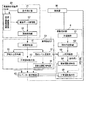
次に、本実施形態のエレベーター装置1の制御系の構成について説明する。図2は、本実施形態のエレベーター装置1の制御系の構成を示すブロック図である。図2に示すように、本実施形態のエレベーター装置1は、上述した制御部50と、エレベーター制御装置40と、振動感知部8と、昇降路検査装置20と、異常診断部30とを備える。
2. Control system of the elevator device Next, the configuration of the control system of the elevator device 1 of the present embodiment will be described. FIG. 2 is a block diagram showing a configuration of a control system of the elevator device 1 of the present embodiment. As shown in FIG. 2, the elevator device 1 of the present embodiment includes the above-mentioned
[エレベーター制御装置]
エレベーター制御装置40は、制御部50の制御の下、かご2を昇降させるための巻上機6の駆動、かご2におけるかごドアの開閉など、エレベーター装置1の運転に関わる制御をする。エレベーター制御装置40は、平常時におけるエレベーター装置1の通常運転の他に、振動感知部8において地震などにより一定レベル以上の揺れを検知した場合には、後述する振動感知部8及び異常診断部30からの指令に基づいて巻上機6の駆動を制御する。
[Elevator control device]
Under the control of the
[振動感知部]
振動感知部8は、加速度計81と、振れ幅演算部82と、比較判断部83と、管制運転指令部84と、平常運転指令部85とで構成されている。加速度計81は、機械室5の揺れを検知するものであり、互いに直交する水平方向(x,y方向)の加速度検出機能を有する。この加速度計81で得られた信号は、振れ幅演算部82に送信される。振れ幅演算部82は、加速度計81から送られてきた信号から、エレベーター装置1のデータに基づいて長尺物の振れ幅(振れ量)を算出する。
[Vibration detector]
The
ところで、巨大地震が発生した場合、遠く離れた場所では、比較的周期の長い長周期地震動が発生する。長周期地震動の揺れの周期と建物自身の固有周期とが近い場合には、建物が共振し、大きな揺れが発生する。そして、建物に大きな揺れが発生すると、昇降路18内の主索4や釣合ロープ12、トラベリングケーブル17などの長尺物が大きく揺れる。例えば、主索4の振れ量に着目した場合、かご2が、主索4が建物の揺れに共振する位置にあった場合において最も主索4が大きく揺れ、特に、機械室5とかご2のほぼ中心位置、或いは機械室5と釣合おもり3のほぼ中心位置において、その振れ幅が最も大きくなる。したがって、本実施形態では、振れ幅演算部82は、長尺物が建物の揺れに共振する条件下において、その長尺物が一番大きく振れる幅をその長尺物の振れ幅として算出するものとする。
By the way, when a huge earthquake occurs, a long-period ground motion with a relatively long period occurs in a distant place. When the period of shaking of long-period ground motion is close to the natural period of the building itself, the building resonates and large shaking occurs. Then, when a large shaking occurs in the building, long objects such as the
比較判断部83は、振れ幅演算部82で算出された長尺物の振れ幅と、予め設定されている感知レベルとを比較して、その差を検出し、算出された振れ幅が感知レベル以上であるか、感知レベル未満であるかを判断する。ここで、「感知レベル」とは、長尺物の振れ幅が、管制運転が必要な振れ幅であるか否かを感知するために設定された振れ幅の基準値であり、長尺物が昇降路18の内部機器に衝突、或いは引っ掛からない振れ幅であるか否かを感知するための基準値である。
The
図3は、建物の振動時に主索4が振れた場合を模式的に示した図である。図3の一点鎖線a1で示す仮想線は、主索4が比較判断部83で予め設定されている感知レベルW0で振動した場合の主索4の軌跡を示したものである。
FIG. 3 is a diagram schematically showing a case where the
主索4の振動に着目した場合、主索4が建物の揺れに共振する位置にかごが配置された時において、機械室5とかご2のほぼ中心位置Oにおける許容可能な最大の振れ幅W0が、比較判断部83における「感知レベル」として設定されている。ここで、許容可能な最大の振れ幅とは、昇降路18の内部機器に主索4が接触しない範囲で許容される最大の振れ幅であり、本実施形態では、この許容される最大の振れ幅W0が感知レベルW0として予め設定されているものとする。
Focusing on the vibration of the
比較判断部83において主索4の振れ幅が感知レベルW0未満であると判断された場合には、比較判断部83は、主索4を「振れ無し」と判断する。一方、比較判断部83において、主索4の振れ幅が感知レベルW0以上であると判断された場合には、比較判断部83は、主索4を「振れ有り」と判断する。
When the
ここでは、主索4に着目して説明したが、釣合ロープ12や調速機ロープ9などそれぞれの長尺物についても同様に「振れ有り」か「振れ無し」かが判断される。
Here, although the explanation has been focused on the
比較判断部83が、振れ幅演算部82で算出された長尺物の振れ幅と感知レベルとを比較して「振れ無し」と判断した場合には、その信号を平常運転指令部85に送信する。平常運転指令部85は、比較判断部83から信号に基づいて、エレベーター制御装置40に平常運転の指令を与える。
When the
一方、比較判断部83は、振れ幅演算部82で算出された長尺物の振れ幅と感知レベルとを比較して「振れ有り」と判断した場合には、その信号を管制運転指令部84に送信する。管制運転指令部84は、比較判断部83から受け取った信号に応じて、エレベーター制御装置40に、管制運転させる指令を与える。ここで、「振れ有り」と判断された場合、その振れが、「振れ高」であるか、「振れ低」であるかに応じて管制運転の方法が異なる。この「振れ高」及び「振れ低」とは、昇降機耐震設計・施工指針に示された感知レベルである。
On the other hand, when the
「振れ高」は、長尺物が昇降路18の内部機器と接触する可能性のある振れ状態に設定されており、「振れ高」と判断された場合には、管制運転指令部84は、かご2を最寄り階へ停止後、運転休止状態とする指令をエレベーター制御装置40に与える。その後、本実施形態では、後述する昇降路検査装置20により昇降路18内の異常を検査すると共に、異常診断部30において、発生した異常を診断して、その診断結果に応じた指令をエレベーター制御装置40に与える。昇降路検査装置20及び異常診断部30については後で詳述する。
The "runout height" is set to a runout state in which a long object may come into contact with the internal equipment of the
一方、「振れ低」は、長尺物の振れが「振れ高」の50〜70%程度の振れ状態に設定されており、「振れ低」と判断された場合には、管制運転指令部84は、かご2を最寄り階へ停止後、一定時間が経過した後に平常運転に移行する指令を与える。
On the other hand, "low runout" is set so that the runout of a long object is about 50 to 70% of the "high runout", and when it is determined that the runout is "low runout", the control
ところで、長周期地震動は加速度が小さく、一般的な加速度式地震感知器では長周期地震動は感知できない。これに対し、本実施形態では、揺れ幅演算部82において、長周期地震動の揺れとエレベーター装置1のデータから長尺物の振れ幅を算出することができる。これにより、長周期地震動により、長尺物が振れて昇降路18の内部機器に接触、或いは引っ掛かりが発生する前に適切な管制運転を実施することができる。
By the way, long-period ground motion has a small acceleration, and a general acceleration-type seismic detector cannot detect long-period ground motion. On the other hand, in the present embodiment, the shaking
また、本実施形態では、所定の条件下において、比較判断部83で設定されている「感知レベル」が後述の感知レベル変更部34によって変更されるところに特徴を有する。
Further, the present embodiment is characterized in that the "sensing level" set in the
[昇降路検査装置]
昇降路検査装置20は、振動感知部8が、エレベーター制御装置40にかご2を管制運転させてから運転停止状態とする管制運転指令を与えた場合において、昇降路18の内部機器に変形・破断などの異常があるかどうかを検査する装置である。昇降路検査装置20は、第1撮像装置15と、第2撮像装置16と、条件設定部21と、画像データ取得部22と、画像解析部23とを備える。
[Hoistway inspection device]
The
条件設定部21は、制御部50の制御の下、第1撮像装置15及び第2撮像装置16における撮影条件を設定して第1撮像装置15及び第2撮像装置16に入力すると共に、撮影時におけるかご2の昇降速度を設定してエレベーター制御装置40に入力する。条件設定部21では、例えば、撮影時間、撮影のタイミング、撮影する方向、撮影する範囲、動画又は静止画像の切り換え、フラッシュなどの、昇降路18内の検査に必要な撮影条件を設定する。
Under the control of the
第1撮像装置15及び第2撮像装置16は、制御部50の制御の下、条件設定部21によって設定された条件で、昇降路18内を撮影する。なお、第1撮像装置15及び第2撮像装置16において昇降路18内を撮影する際には、エレベーター制御装置40により、かご2は条件設定部21で設定された速度で昇降路18内を昇降する。昇降路18内の撮影時では、例えば通常のかご2の昇降速度よりも低速となるようにかご2の昇降速度が制御される。
The
画像データ取得部22は、制御部50の制御の下、第1撮像装置15及び第2撮像装置16から、撮影された画像のデータを取得する。画像データ取得部22は、第1撮像装置15及び第2撮像装置16から取得した画像のデータを画像解析部23に送信する。
The image
画像解析部23は、制御部50の制御の下、画像データ取得部22から送信されてきた画像データに必要な画像処理を行う。画像解析部23では、予め格納された解析診断プログラムに従って昇降路18内のどの位置に、変形や破断などどのような異常が発生しているかが解析され、その解析データを、異常診断部30を構成する画像診断部31に送信する。
Under the control of the
[異常診断部]
異常診断部30は、昇降路18内の機器に変形・破断などの異常が、かご2の昇降に影響するかどうかを診断する装置であり、画像診断部31と、運転休止指令部32と、平常運転指令部33と、感知レベル変更部34と、仮復旧運転指令部35とを備える。
[Abnormality Diagnosis Department]
The
画像診断部31は、制御部50の制御の下、画像解析部23から送られてきた解析データと、平常運転時に予め取得しておいた画像データに基づく解析データとを用い、昇降路18の内部機器における変形・破断などの異常の有無を診断する。まず、画像診断部31は、昇降路18内の状態を下記の2種類の場合に分ける診断を行う。
(A)かご2の走行に影響する重大な異常が昇降路18内に発生している場合
(B)かご2の走行に影響する重大な異常が昇降路18内に発生していない場合
Under the control of the
(A) When a serious abnormality affecting the running of the
ここで、「かご2の走行に影響する重大な異常」は、昇降路18の内部機器とかご2とが緩衝する可能性が有るなど、かご2の走行に影響する異常を意味する。
Here, the "serious abnormality affecting the running of the
画像診断部31が、上記の(A)と診断した場合、すなわち、かご2の走行に影響する重大な異常が昇降路18内に発生している場合は、運転休止に係る信号を運転休止指令部32に送る。
When the
一方、画像診断部31において、(B)と診断された場合、すなわち、かご2の走行に影響する重大な異常が昇降路18内に発生していないと診断された場合には、画像診断部31は、さらに、下記の2種類の場合に分ける診断を行う。
(C)長尺物が引っ掛かりリスクが増加する異常が発生している場合
(D)長尺物が引っ掛かるリスクが増加する異常が発生していない場合
On the other hand, when the
(C) When there is an abnormality that increases the risk of being caught by a long object (D) When there is no abnormality that increases the risk of being caught by a long object
画像診断部31が、上記の(C)と診断した場合、すなわち、長尺物が引っ掛かるリスクが増加する異常が発生していると診断した場合は、画像診断部31は、感知レベル変更部34に診断結果を送る。図3に示す異常Eは、上記の(C)と診断される異常の一例である。「長尺物が引っ掛かるリスクが増加する異常」は、振動感知部8で設定されている「感知レベル」に基づいて診断される。図3を用いて異常Eが発生した場合の引っ掛かりリスクの診断方法について説明する。
When the
長尺物の振れ幅は、中心位置から離れる程小さくなる。このため、主索4の中心部Oにおける振れ幅から、主索4の各位置における振れ幅を算出できるよう、主索の中心部Oからの距離に応じた振れ幅の変化に関する倍率N(0<N≦1)を事前に算出しておき、制御部50の記憶部(図示を省略する)に記憶させておく。そして、異常Eが検出された場合、画像診断部31は、現在の感知レベルW0と、中心部Oからの距離Hにおいて定められている倍率N1とから、異常Eが発生した高さにおける主索4の振れ幅を算出する。主索4の中心部Oから距離Hだけ離れた位置での感知レベルW0に対応する振れ幅W1は、W1=N1W0となる。
The swing width of a long object becomes smaller as the distance from the center position increases. Therefore, a magnification N (0) regarding the change in the swing width according to the distance from the center portion O of the main rope so that the swing width at each position of the
次に、画像診断部31は、主索4から異常Eまでの距離xが、その位置における感知レベルW0の振れ幅W1よりも大きいか小さいかを診断する。図3に示すように、x<W1であった場合には、画像診断部31は、「長尺物が引っ掛かるリスクが増加する異常が発生している」と診断し、その診断結果を感知レベル変更部34に送る。
Next, the
一方、画像診断部31が、上記の(D)と診断した場合、すなわち、長尺物が引っ掛かるリスクが増加する異常が発生していない場合は、画像診断部31は、平常運転に係る信号を平常運転指令部33に送る。例えば、異常が発生している場合においても、その異常が図3に示す主索4の感知レベルW0の内側に無い場合、すなわち、一点鎖線a1で示す仮想線内に異常が無い場合には、画像診断部31は、上記の(D)と診断する。
On the other hand, when the
感知レベル変更部34は、制御部50の制御の下、画像診断部31から送られた診断結果に基づき、新たな感知レベルを設定する。図3の二点鎖線a2で示す仮想線は、異常Eが主索4付近に発生した場合に設定される新たな感知レベルWrで振動した場合の主索4の軌跡を示したものである。新たな感知レベルWrは、図3に示すように、異常Eに主索4が触れない範囲内に設定される。この設定方法について説明する。
Under the control of the
感知レベル変更部34は、異常Eが発生した位置(高さ)において、主索4が異常Eに当たらない振れ幅Waを算出する。そして、この振れ幅Waを用いると、主索4の中心部Oにおける振れ幅Wrは、Wr=Wa/N1で算出することができる。感知レベル変更部34は、制御部50の制御の下、この振れ幅Wrを新たな感知レベルWrとし、振動感知部8の比較判断部83における感知レベルW0を感知レベルWrに変更する。
The sensing
そして、感知レベル変更部34は、新たな感知レベルWrを設定した後、仮復旧運転に係る信号を仮復旧運転指令部35に送信する。なお、画像解析部23、画像診断部31及び感知レベル変更部34で用いた各データや解析結果等は、その都度、制御部50に設けられた記憶部(図示を省略する)に記憶される。
Then, the sensing
平常運転指令部33は、制御部50の制御の下、エレベーター制御装置40に平常運転の指令を与える。また、運転休止指令部32は、制御部50の制御の下、エレベーター制御装置40に、運転を休止する指令を与える。また、仮復旧運転指令部35は、制御部50の制御の下、エレベーター制御装置40に、仮復旧運転の指令を与える。そして、エレベーター制御装置40は、制御部50の制御の下、与えられた指令に基づいて、かご2の運転、休止を制御する。
The normal operation command unit 33 gives a command for normal operation to the elevator control device 40 under the control of the
以上のようにして、本実施形態では、昇降路検査装置20で検査した結果に基づき、異常診断部30において昇降路18内で発生した異常がどの程度であるかを判断する。そして、その異常がどの程度かによって、平常運転するか、仮復旧運転するか、運転休止とするかを決定する。
As described above, in the present embodiment, based on the result of the inspection by the
なお、上述した、(A)〜(D)に係る判断基準は、エレベーター装置1の仕様によって適宜設定することができる。例えば、主索振動に着目した場合、主索4から発生した異常部分までの距離で、「かご2の走行に影響する重大な異常が昇降路内に発生している」か否か、「長尺物が引っ掛かるリスクが増加する異常」か否かを判断することができる。
The above-mentioned determination criteria according to (A) to (D) can be appropriately set according to the specifications of the elevator device 1. For example, when focusing on the vibration of the main rope, whether or not "a serious abnormality affecting the running of the
また、本実施形態では、画像診断部31において、昇降路検査装置20で取得した画像と、平常時に撮影した昇降路18内の画像とを比較して昇降路18内に発生した異常を検出する方法を示した。しかし、異常診断の手法はこれに限られるものではなく、例えば、昇降路検査装置20で検査する昇降路18の検査箇所に事前にマーキングを施しておき、その箇所の変形量を画像データから検出する方法などを用いてもよい。
Further, in the present embodiment, the
また、上述の説明では、主索振動に着目し、画像診断部31の診断方法や、感知レベル変更部34の変更方法について説明したが、本実施形態では、画像診断部31ではそれぞれの長尺物毎に画像診断を行い、感知レベル変更部34では長尺物毎に感知レベルの変更を行ってもよい。これにより、より安全なエレベーター走行を行うことが可能となる。
Further, in the above description, focusing on the vibration of the main cord, the diagnostic method of the
3.エレベーター装置の制御方法
次に、本実施形態のエレベーター装置1の制御方法の1例について説明する。図4は、本実施形態のエレベーター装置1の制御方法を示すフローチャートである。ここでは、地震又は強風が発生し、建物が揺れることにより、振動感知部8における比較判断部83において「振れ有」と判断された後の段階から説明する。すなわち、加速度計81における振動の検知結果に基づいて、振れ幅演算部82で算出された長尺物の振れ幅が感知レベルに達していると判断された後の処理から説明する。
3. 3. Elevator device control method Next, an example of a control method for the elevator device 1 of the present embodiment will be described. FIG. 4 is a flowchart showing a control method of the elevator device 1 of the present embodiment. Here, the description will be made from the stage after the
地震又は強風によって比較判断部83が「振れ有」と判断した場合には、制御部50の制御の下、管制運転指令部84はエレベーター制御装置40に管制運転を行う指令を与え、これにより、管制運転が開始される。管制運転の内容については、前述したように、「振れ高」か「振れ低」かによって変わってくるが、ここでは、「振れ高」と判断された場合として説明を続ける。
When the
管制運転が開始されると、かご2は最寄り階に停止した後、運転を停止し(ステップS2)、かご2内に乗客が居た場合には最寄り階に降車させる。その後、振動感知部8において、長尺物の振れが集束したことを確認する(ステップS3)。
When the control operation is started, the
その後、図示を省略するかご内荷重検出器からの信号によって、かご2内に乗客が居ないことを確認する(ステップS4)。次に、昇降路検査装置20を用いて、昇降路18内の検査を開始する(ステップS5)。ここでは、制御部50の制御の下、予め設定された範囲でかご2を低速運転しながら、第1撮像装置15及び第2撮像装置16で対象の昇降路18内の撮影を行う。第1撮像装置15及び第2撮像装置16は、条件設定部21によって設定されている範囲及び条件の下、昇降路18内の撮影を行う。
After that, it is confirmed that there are no passengers in the
第1撮像装置15及び第2撮像装置16で撮影された画像は、画像データ取得部22を介して画像解析部23に送られ、画像解析部23において、予め設定されている解析診断プログラムに従って解析される。そして、画像解析部23において得られた解析データが、異常診断部30における画像診断部31に送られる。
The images taken by the first
次に、画像診断部31において、画像解析部23から送られてきた解析データと、平常運転時に取得した解析データとを比較して、かご2の走行に影響する重大な異常が有るか否かを判断する(ステップS6)。
Next, the
ステップS6において「YES」の場合、すなわち、かご2の走行に影響する重大な異常があると判断された場合には、運転休止に係る信号を運転休止指令部32に送ると共に、運転休止指令部32は、エレベーター制御装置40に運転休止の指令を与える(ステップS7)。これにより、エレベーター装置1の運転が休止される。この場合は、現場に出動した保守員の修理点検を経てエレベーター装置1の運行を復旧させることができる。
If "YES" in step S6, that is, if it is determined that there is a serious abnormality affecting the running of the
一方、ステップS6において「NO」の場合、すなわち、かご2の走行に影響する重大な異常が無いと判断された場合、画像診断部31は、さらに、長尺物の引っ掛かりリスクが増加する異常があるか否かを判断する(ステップS8)。ここでの診断方法は、図3を用いて説明した通りである。
On the other hand, if "NO" is set in step S6, that is, if it is determined that there is no serious abnormality affecting the running of the
ステップS8において「NO」の場合、すなわち、長尺物の引っ掛かりリスクが増加する異常が無いと判断された場合、平常運転に係る信号を平常運転指令部33に送ると共に、平常運転指令部33は、エレベーター装置1に平常運転の指令を与える(ステップS9)。これにより、エレベーター装置1は、平常運転を開始する。 If "NO" is set in step S8, that is, if it is determined that there is no abnormality that increases the risk of catching a long object, a signal related to normal operation is sent to the normal operation command unit 33, and the normal operation command unit 33 , Gives a command for normal operation to the elevator device 1 (step S9). As a result, the elevator device 1 starts normal operation.
ステップS8において「YES」の場合、すなわち、長尺物の引っ掛かりリスクが増加する異常が有ると判断された場合、比較判断部83の感知レベルを変更する(ステップS10)。ここでは、図3を用いて説明したように、感知レベル変更部34は、画像診断部31から送られてくる診断結果に基づいて、新たな感知レベルを算出する。そして、新たな感知レベルを比較判断部に送信し、比較判断部に保持されている感知レベルを変更する。
If "YES" in step S8, that is, if it is determined that there is an abnormality that increases the risk of catching a long object, the sensing level of the
その後、感知レベル変更部34は、仮復旧運転に係る信号を仮復旧運転指令部35に送ると共に、仮復旧運転指令部35は、エレベーター制御装置40に仮復旧運転の指令を与える(ステップS11)。
After that, the detection
なお、ステップS5における昇降路内検査を行うに当たって、かご2を低速で昇降させるが、昇降路18内の検査時に長尺物の引っ掛かりが発生していることを検知した場合には、すぐに運転を停止することが好ましい。かご2の昇降時における長尺物の引っ掛かりは、第1撮像装置15及び第2撮像装置16の画像データによる診断のほか、巻上機6のトルクや、長尺物の張力を測定することで検知することができる。
In the hoistway inspection in step S5, the
本実施形態のエレベーター装置1によれば、昇降路18の内部機器の変形や破断などの異常が発生したとしても、感知レベル変更部34によって新たな感知レベルを設定することでエレベーター装置1を仮復旧運転させることができる。そして、仮復旧運転させた場合において、再度、地震動などが起こり長尺物の揺れが発生した場合には、新たな感知レベルが設定されているため、昇降路18内の異常部分に長尺物が振れる前にエレベーター装置1の運行を停止することができる。
According to the elevator device 1 of the present embodiment, even if an abnormality such as deformation or breakage of the internal device of the
従来は、振動感知部において「振れ高」と判断された場合には、現場に出動した保守員による昇降路内の機器の点検を経てから運行開始が行われていた。しかしながら、本実施形態では、昇降路検査装置20及び異常診断部30において、エレベーター装置1の運行に問題はないが、再度揺れた場合には長尺物が引っ掛かるリスクが増加する異常があると判断した場合において、感知レベルを変更した上で、仮復旧運転を行う。これにより、再度起こりうる地震動において長尺物の引っ掛かりが発生し、乗客の閉じ込められる事故が発生するリスクを回避した上で、仮復旧運転を開始することができるので、仮復旧運転時の安全を確保することができる。
Conventionally, when the vibration sensing unit determines that the vibration height is high, the maintenance staff dispatched to the site inspects the equipment in the hoistway before starting the operation. However, in the present embodiment, it is determined that there is no problem in the operation of the elevator device 1 in the
また、従来は、振動感知部8において「振れ高」と判断され、エレベーター装置1の運行が停止した場合には、運行の復旧には保守員が現場へ出動し、点検修理を行う必要があった。このため、大規模な地震では、保守員が各建物を順番に回る必要があり、全ての建物でエレベーター装置1を復旧させるまで長い時間を要するという問題があった。これに対し、本実施形態では、「振れ高」であった場合にも、長尺物の引っ掛かりリスクを回避する条件下で仮復旧運転を開始することができる。
In addition, conventionally, when the
そして、従来は、保守員が現場に到着後、昇降路18内の異常発生箇所を保守員が検査していた。これに対し、本実施形態では、異常発生箇所は予め昇降路検査装置20によって検出されるため、保守員の作業時間を短縮することができ、保守員の負担を軽減することができる。
Conventionally, after the maintenance staff arrives at the site, the maintenance staff inspects the location where the abnormality occurs in the
本実施形態では、昇降路検査装置20において、撮像装置を用いたが、かご2の昇降時に発生する騒音や異常音などの音データを利用して異常診断する構成としてもよい。また、音データと画像データとの組み合わせによって異常診断する構成としてもよい。
In the present embodiment, the
以上、本発明について、実施形態に基づいて説明したが、本発明は上述の実施形態に記載した構成に限定されるものではなく、その趣旨を逸脱しない範囲において適宜その構成を変更することができるものである。また、上述した実施形態例は、本発明を分かりやすく説明するために詳細に説明したものであり、必ずしも説明した全ての構成を備えるものに限定されるものではない。例えば、実施形態の構成の一部について、他の構成の追加・削除・置換をすることが可能である。 Although the present invention has been described above based on the embodiment, the present invention is not limited to the configuration described in the above-described embodiment, and the configuration can be appropriately changed without departing from the spirit thereof. It is a thing. In addition, the above-described embodiment has been described in detail in order to explain the present invention in an easy-to-understand manner, and is not necessarily limited to the one including all the described configurations. For example, it is possible to add / delete / replace a part of the configuration of the embodiment with another configuration.
1…エレベーター装置、2…かご、3…釣合おもり、4…主索、5…機械室、6…巻上機、7…主索プーリ、8…振動感知部、9…調速機ロープ、10…調速機、11…調速機プーリ、12…釣合ロープ、13…コンペンプーリ、14…かご枠、15…第1撮像装置、16…第2撮像装置、17…トラベリングケーブル、18…昇降路、19…固定部、20…昇降路検査装置、30…異常診断部、34…感知レベル変更部、40…エレベーター制御装置、50…制御部 1 ... Elevator device, 2 ... Basket, 3 ... Balance weight, 4 ... Main rope, 5 ... Machine room, 6 ... Hoisting machine, 7 ... Main rope pulley, 8 ... Vibration detector, 9 ... Governor rope, 10 ... Governor, 11 ... Governor pulley, 12 ... Balance rope, 13 ... Compen pulley, 14 ... Cage frame, 15 ... 1st imaging device, 16 ... 2nd imaging device, 17 ... Traveling cable, 18 ... Hoistway, 19 ... Fixed unit, 20 ... Hoistway inspection device, 30 ... Abnormality diagnosis unit, 34 ... Sensing level change unit, 40 ... Elevator control device, 50 ... Control unit
Claims (6)
前記昇降路内を昇降自在に走行するかごと、
前記かごの昇降を制御するエレベーター制御装置とを備えるエレベーター装置において、
前記昇降路の振動を検知し、前記検知した結果に基づいて、前記昇降路内に配置された長尺物の振れ幅を算出し、予め設定されている振れ幅の基準値と、前記算出された長尺物の振れ幅とを比較し、この比較結果に基づいて前記エレベーター制御装置に管制運転指令又は平常運転指令を与える振動感知部と、
前記振動感知部が、前記かごを管制運転させてから運転停止状態とする管制運転指令を前記エレベーター制御装置に与えた場合において、前記昇降路内の検査を行う昇降路検査装置と、
前記昇降路検査装置から送られてきたデータから、前記かごの走行に影響する重大な異常は発生していないが、長尺物が引っ掛かるリスクが増加する異常が発生していると診断した場合には、前記振動感知部に設定されている振れ幅の基準値を変更すると共に、前記エレベーター制御装置に仮復旧運転指令を与える異常診断部と
を備えるエレベーター装置。 Hoistway and
A car that can move up and down in the hoistway,
In an elevator device including an elevator control device that controls the raising and lowering of the car,
The vibration of the hoistway is detected , and based on the detected result, the runout width of the long object arranged in the hoistway is calculated, and the reference value of the preset runout width and the calculation are calculated. A vibration sensing unit that compares the swing width of a long object and gives a control operation command or a normal operation command to the elevator control device based on the comparison result.
When the vibration sensing unit gives a control operation command to the elevator control device to stop the operation after controlling the car, the hoistway inspection device that inspects the inside of the hoistway and the hoistway inspection device.
When it is diagnosed from the data sent from the hoistway inspection device that no serious abnormality affecting the running of the car has occurred, but an abnormality that increases the risk of catching a long object has occurred. Is an elevator device including an abnormality diagnosis unit that changes a reference value of a swing width set in the vibration sensing unit and gives a temporary restoration operation command to the elevator control device.
請求項1に記載のエレベーター装置。 When the abnormality diagnosis unit diagnoses that a serious abnormality affecting the running of the car has occurred from the data sent from the hoistway inspection device, the abnormality diagnosis unit issues an operation suspension command to the elevator control device. The elevator device according to claim 1.
請求項1に記載のエレベーター装置。 From the data sent from the hoistway inspection device, the abnormality diagnosis unit has not caused a serious abnormality affecting the running of the car, and an abnormality has occurred that increases the risk of a long object being caught. The elevator device according to claim 1, which gives a normal operation command to the elevator control device when it is diagnosed that the elevator is not.
請求項1〜3のいずれか一項に記載のエレベーター装置。 3. The elevator device according to any one item.
請求項4に記載のエレベーター装置。 The elevator device according to claim 4, wherein the abnormality diagnosis unit performs an abnormality diagnosis using the analysis data of the image sent from the image analysis unit and the data acquired during normal operation.
前記昇降路内を昇降自在に走行するかごと、
前記かごの昇降を制御するエレベーター制御装置と、
前記昇降路の振動を感知する振動感知部と、
昇降路内を検査する昇降路検査装置と、前記昇降路検査装置で得られたデータから異常を診断する異常診断部とを備えるエレベーター装置の制御方法であって、
前記振動感知部で、昇降路の振動を検知し、前記検知した結果に基づいて、昇降路内に配置された長尺物の振れ幅を算出し、予め設定されている振れ幅の基準値と、前記算出された長尺物の振れ幅とを比較し、この比較結果に基づいて前記エレベーター制御装置に管制運転指令又は平常運転指令を与え、
前記振動感知部が前記かごを管制運転させてから運転停止状態とする管制運転指令を前記エレベーター制御装置に与えた場合には、前記昇降路検査装置は、前記昇降路内の検査を行い、
前記異常診断部は、前記昇降路検査装置から送られてきたデータから、前記昇降路内に発生した異常を診断し、前記異常診断部が、前記かごの走行に影響する重大な異常は発生していないが、長尺物が引っ掛かるリスクが増加する異常が発生していると診断した場合には、前記振動感知部に設定されている振れ幅の基準値を変更すると共に、前記エレベーター制御装置に仮復旧運転指令を与える
エレベーター装置の制御方法。 Hoistway and
A car that can move up and down in the hoistway,
An elevator control device that controls the raising and lowering of the car,
A vibration sensing unit that detects the vibration of the hoistway and
It is a control method of an elevator device including a hoistway inspection device for inspecting the inside of the hoistway and an abnormality diagnosis unit for diagnosing an abnormality from the data obtained by the hoistway inspection device.
The vibration sensing unit detects the vibration of the hoistway, calculates the runout width of a long object placed in the hoistway based on the detected result, and sets it as a preset reference value for the hoistway. , The calculated swing width of the long object is compared, and a control operation command or a normal operation command is given to the elevator control device based on the comparison result.
When the vibration sensing unit gives a control operation command to the elevator control device to put the car into a control operation and then stop the operation, the hoistway inspection device inspects the inside of the hoistway.
The abnormality diagnosis unit diagnoses an abnormality that has occurred in the hoistway from the data sent from the hoistway inspection device, and the abnormality diagnosis unit causes a serious abnormality that affects the running of the car. However, if it is diagnosed that an abnormality that increases the risk of catching a long object has occurred, the reference value of the swing width set in the vibration sensing unit is changed, and the elevator control device is used. A control method for an elevator device that gives a temporary restoration operation command.
Priority Applications (1)
| Application Number | Priority Date | Filing Date | Title |
|---|---|---|---|
| JP2017080285A JP6778648B2 (en) | 2017-04-14 | 2017-04-14 | Elevator device and control method of elevator device |
Applications Claiming Priority (1)
| Application Number | Priority Date | Filing Date | Title |
|---|---|---|---|
| JP2017080285A JP6778648B2 (en) | 2017-04-14 | 2017-04-14 | Elevator device and control method of elevator device |
Publications (3)
| Publication Number | Publication Date |
|---|---|
| JP2018177473A JP2018177473A (en) | 2018-11-15 |
| JP2018177473A5 JP2018177473A5 (en) | 2019-10-17 |
| JP6778648B2 true JP6778648B2 (en) | 2020-11-04 |
Family
ID=64282201
Family Applications (1)
| Application Number | Title | Priority Date | Filing Date |
|---|---|---|---|
| JP2017080285A Active JP6778648B2 (en) | 2017-04-14 | 2017-04-14 | Elevator device and control method of elevator device |
Country Status (1)
| Country | Link |
|---|---|
| JP (1) | JP6778648B2 (en) |
Families Citing this family (5)
| Publication number | Priority date | Publication date | Assignee | Title |
|---|---|---|---|---|
| CN110980467B (en) * | 2019-12-24 | 2021-04-27 | 福建快科城建增设电梯股份有限公司 | Car running quality detection method |
| US11390488B2 (en) * | 2020-06-26 | 2022-07-19 | Otis Elevator Company | Visual inspection diagnostics |
| JP7226657B2 (en) * | 2020-08-04 | 2023-02-21 | 三菱電機ビルソリューションズ株式会社 | judgment system |
| CN114261862B (en) * | 2021-11-08 | 2024-03-19 | 闽江学院 | Elevator running condition monitoring method and system |
| WO2024057445A1 (en) * | 2022-09-14 | 2024-03-21 | 三菱電機ビルソリューションズ株式会社 | Elevator |
Family Cites Families (9)
| Publication number | Priority date | Publication date | Assignee | Title |
|---|---|---|---|---|
| JPH09286576A (en) * | 1996-04-24 | 1997-11-04 | Hitachi Building Syst Co Ltd | Image monitoring device for elevator |
| JP5168831B2 (en) * | 2006-07-03 | 2013-03-27 | フジテック株式会社 | Elevator seismic control device |
| JP5045080B2 (en) * | 2006-11-29 | 2012-10-10 | フジテック株式会社 | Elevator seismic control device |
| JP5035012B2 (en) * | 2008-02-22 | 2012-09-26 | 三菱電機ビルテクノサービス株式会社 | Elevator control device and control method |
| JP2011116519A (en) * | 2009-12-04 | 2011-06-16 | Toshiba Elevator Co Ltd | Long-size object vibration sensor control device and elevator system |
| JP5240253B2 (en) * | 2010-08-19 | 2013-07-17 | 三菱電機株式会社 | Elevator control operation device |
| WO2014141366A1 (en) * | 2013-03-11 | 2014-09-18 | 三菱電機株式会社 | Elevator device |
| JP6132690B2 (en) * | 2013-07-19 | 2017-05-24 | 三菱電機ビルテクノサービス株式会社 | Elevator long object inspection device and elevator long object inspection method |
| JP2016141519A (en) * | 2015-02-02 | 2016-08-08 | 株式会社日立製作所 | Elevator device and operation control method for elevator device |
-
2017
- 2017-04-14 JP JP2017080285A patent/JP6778648B2/en active Active
Also Published As
| Publication number | Publication date |
|---|---|
| JP2018177473A (en) | 2018-11-15 |
Similar Documents
| Publication | Publication Date | Title |
|---|---|---|
| JP6778648B2 (en) | Elevator device and control method of elevator device | |
| CN108569603B (en) | Elevator inspection device, elevator inspection system, manufacturing method thereof, and terminal device | |
| JP5224933B2 (en) | Elevator restoration operation method and apparatus | |
| JP6769929B2 (en) | Elevator inspection system and elevator | |
| JP2009274805A (en) | Elevator malfunction detecting device | |
| JP2007091460A (en) | Elevator device and its control method | |
| JP5704700B2 (en) | Elevator control device and sensor | |
| JP2008063112A (en) | Rope swing monitoring control device for elevator | |
| JP6997680B2 (en) | Elevator abnormality monitoring system and elevator abnormality monitoring method | |
| JP2015020863A (en) | Elevator long object inspection device and elevator long object inspection method | |
| JP2014009098A (en) | Device and method for controlled operation of elevator | |
| JP5401281B2 (en) | Elevator rope swing detection device and automatic earthquake recovery operation control method using the same | |
| JP5287316B2 (en) | Elevator equipment | |
| JP6404406B1 (en) | Elevator control device and elevator control method | |
| JP6163095B2 (en) | Monitoring system in elevator hoistway | |
| JP6480840B2 (en) | Elevator and control method of elevator | |
| JP2007176624A (en) | Elevator | |
| JP2009091100A (en) | Earthquake emergency operation control system of elevator | |
| JP4844410B2 (en) | Hook detection device for elevator ropes | |
| JP5535441B2 (en) | Elevator control operation device | |
| JP6776955B2 (en) | Abnormal sound detection method | |
| JP6494793B2 (en) | Elevator and elevator operation method | |
| JP6801052B2 (en) | Elevator load detector | |
| JP4867813B2 (en) | Elevator seismic control operation system | |
| JP6483223B1 (en) | Elevator remote diagnosis operation method, elevator control device, and elevator remote diagnosis operation program |
Legal Events
| Date | Code | Title | Description |
|---|---|---|---|
| A521 | Written amendment |
Free format text: JAPANESE INTERMEDIATE CODE: A523 Effective date: 20190905 |
|
| A621 | Written request for application examination |
Free format text: JAPANESE INTERMEDIATE CODE: A621 Effective date: 20190905 |
|
| A977 | Report on retrieval |
Free format text: JAPANESE INTERMEDIATE CODE: A971007 Effective date: 20200727 |
|
| A131 | Notification of reasons for refusal |
Free format text: JAPANESE INTERMEDIATE CODE: A131 Effective date: 20200804 |
|
| A521 | Written amendment |
Free format text: JAPANESE INTERMEDIATE CODE: A523 Effective date: 20200901 |
|
| TRDD | Decision of grant or rejection written | ||
| A01 | Written decision to grant a patent or to grant a registration (utility model) |
Free format text: JAPANESE INTERMEDIATE CODE: A01 Effective date: 20200929 |
|
| A61 | First payment of annual fees (during grant procedure) |
Free format text: JAPANESE INTERMEDIATE CODE: A61 Effective date: 20201012 |
|
| R150 | Certificate of patent or registration of utility model |
Ref document number: 6778648 Country of ref document: JP Free format text: JAPANESE INTERMEDIATE CODE: R150 |