JP6769934B2 - Game machine - Google Patents
Game machine Download PDFInfo
- Publication number
- JP6769934B2 JP6769934B2 JP2017161902A JP2017161902A JP6769934B2 JP 6769934 B2 JP6769934 B2 JP 6769934B2 JP 2017161902 A JP2017161902 A JP 2017161902A JP 2017161902 A JP2017161902 A JP 2017161902A JP 6769934 B2 JP6769934 B2 JP 6769934B2
- Authority
- JP
- Japan
- Prior art keywords
- display
- hold
- special symbol
- jackpot
- command
- Prior art date
- Legal status (The legal status is an assumption and is not a legal conclusion. Google has not performed a legal analysis and makes no representation as to the accuracy of the status listed.)
- Active
Links
Images


Landscapes
- Display Devices Of Pinball Game Machines (AREA)
Description
本発明は、パチンコ遊技機等の遊技機に関する。 The present invention relates to a gaming machine such as a pachinko gaming machine.
遊技機として、遊技媒体である遊技球を発射装置によって遊技領域に発射し、遊技領域
に設けられている入賞口などの入賞領域に遊技球が入賞すると、所定の入賞価値を遊技者
に与えるパチンコ遊技機がある。また、遊技機として、所定の賭数を設定し、スタート操
作が行われたことに基づいて、複数種類の識別情報の可変表示が行われるスロットマシン
がある。
As a game machine, a pachinko machine that launches a game ball, which is a game medium, into a game area by a launching device, and when the game ball wins a prize in a prize area such as a prize opening provided in the game area, a pachinko machine that gives a predetermined prize value to the player. There is a game machine. Further, as a game machine, there is a slot machine in which a predetermined number of bets is set and a plurality of types of identification information are variably displayed based on a start operation.
そのような遊技機における演出としてバトル演出がある。バトル演出では、敵の体力が
体力バーなどの形式で表示されることが多い。例えば、特許文献1には、敵のHP表示を
行うものが開示されている。
There is a battle production as a production in such a game machine. In battle production, the physical strength of the enemy is often displayed in the form of a physical strength bar or the like. For example,
しかしながら、特許文献1に記載された遊技機では、バトル演出表示などの所定表示と
、HP表示などの特定表示とが連携した表示を行うことができていないため、興趣を十分
に向上させることができなかった。
However, in the gaming machine described in
そこで、本発明は、所定表示と特定表示とを用いて興趣を向上させることが可能な遊技
機を提供することを目的とする。
Therefore, an object of the present invention is to provide a game machine capable of improving the interest by using a predetermined display and a specific display.
(1)遊技を行うことが可能な遊技機(例えば、パチンコ遊技機1、スロットマシン等)であって、
有利状態(例えば、大当り、突確、ART(AT)、ボーナス等)へ制御されるかを、特別態様を含む複数種類の表示態様のうちいずれかの所定表示(例えば、バトル等)を行うことによって示唆する示唆演出(例えば、バトル演出等)を実行する示唆演出実行手段(例えば、演出制御基板等)と、
前記示唆演出における演出状態(例えば、味方が優勢か否か等)を、特定表示(例えば、ゲージG等)の表示態様を変化(例えば、体力バーを減少等)させることによって報知する報知手段(例えば、演出制御基板等)と、
を備え、
前記報知手段は、
特定表示が特定態様となった場合に、前記示唆演出の演出状態が遊技者にとって有利な演出状態であることを報知し、
所定表示の表示態様(例えば、弱攻撃、中攻撃発生時のバトル等)に対応することなく特定表示の表示態様を変化させる第1変化パターンと、所定表示の表示態様(例えば、強攻撃発生時のバトル等)に対応して、該所定表示を特定表示に作用させ、特定表示の表示態様を変化させる第2変化パターンと、の少なくとも一方で、特定表示の表示態様を変化させることによって前記示唆演出における演出状態を報知し、
前記第2変化パターンにおいて、前記特別態様の所定表示が特定表示に作用した場合に、該特定表示を動作させてから表示態様を前記特定態様へ変化させる遊技機。
(1) A gaming machine capable of playing a game (for example, a
Whether to be controlled to an advantageous state (for example, big hit, sudden probability, ART (AT), bonus, etc.) is determined by performing a predetermined display (for example, battle, etc.) of a plurality of types of display modes including a special mode . A suggestion effect execution means (for example, an effect control board) for executing a suggestion effect (for example, a battle effect) and
A notification means (for example, reducing the physical strength bar, etc.) for notifying the effect state (for example, whether or not an ally is superior) in the suggestion effect by changing the display mode of the specific display (for example, gauge G, etc.). For example, production control board, etc.)
With
The notification means is
When the specific display becomes a specific mode, the effect state of the suggestion effect is notified that the effect state is advantageous to the player.
The first change pattern that changes the display mode of the specific display without corresponding to the display mode of the predetermined display (for example, a battle when a weak attack or a medium attack occurs) and the display mode of the predetermined display (for example, when a strong attack occurs). The above suggestion by changing the display mode of the specific display, at least one of the second change pattern in which the predetermined display acts on the specific display and changes the display mode of the specific display in response to the battle, etc. Notify the production status in the production,
In the second change pattern, when the predetermined display of the special mode acts on the specific display, the gaming machine that changes the display mode to the specific mode after operating the specific display .
このような構成によれば、所定表示と特定表示とを用いて興趣を向上させることが可能
となり、遊技者の興趣を向上できる。
According to such a configuration, it is possible to improve the interest of the player by using the predetermined display and the specific display, and it is possible to improve the interest of the player.
本実施形態では、所定表示として、味方Mと相手Aの1対1のバトルを例に説明したが
、これに限るものではない。例えば、味方1人で相手が2人以上など、味方と相手の人数
は何人であってもよい。さらに、ロボット対ロボットや、人間対構造物などでもよく、人
間に限るものではない。なお、人間対構造物として、例えば武将が城門を突破する武将対
城門などが挙げられる。この場合の所定表示は、バトルに代えて城門攻撃となり、特定表
示は、体力に代えて城門の強度などとなる。なお、所定表示は、演出の要素のうちの一部
の要素であってもよい。例えば、1対1のバトルにおける一方であってもよい。すなわち
、所定表示は、演出全体でなくてもよい。
In the present embodiment, a one-to-one battle between an ally M and an opponent A has been described as an example as a predetermined display, but the present invention is not limited to this. For example, the number of allies and opponents may be any number, such as one ally and two or more opponents. Furthermore, it may be robot-to-robot or human-to-structure, and is not limited to humans. In addition, as a human vs. structure, for example, a military commander vs. a castle gate in which a military commander breaks through the castle gate can be mentioned. In this case, the predetermined display is a castle gate attack instead of the battle, and the specific display is the strength of the castle gate instead of the physical strength. In addition, the predetermined display may be a part of the elements of the effect. For example, it may be one in a one-on-one battle. That is, the predetermined display does not have to be the entire effect.
本実施形態では、特定表示としてゲージGを例に説明したが、これに限るものではない
。例えば、数字そのものを用いるようにしてもよい。具体的には、バトルを、味方1人に
相手が100人で、1ターンごとに相手を攻撃し、人数を減らしていくバトルとしたとき
、バトルごとに、残りの人数を特定表示として表示する。そして、敵が吹き飛ばされたと
きには、残り人数を示す数字も吹き飛ばされ、その後、残り人数を表示するようにする。
In the present embodiment, the gauge G has been described as an example as a specific display, but the present invention is not limited to this. For example, the numbers themselves may be used. Specifically, when the battle is a battle in which one ally has 100 opponents, attacks the opponent every turn, and reduces the number of people, the remaining number of people is displayed as a specific display for each battle. .. Then, when the enemy is blown away, the number indicating the remaining number of people is also blown away, and then the remaining number of people is displayed.
特定表示として、ゲージや数字の他に、針メーターやエッジワイズタイプのメーターで
あってもよい。また、特定表示がいずれの態様であっても、演出表示装置9に表示しても
よいし、演出表示装置9とは異なる表示部に特定表示を表示してもよい。また、例えば針
メーターは、機械式メーターであってもよい。演出表示装置9とは異なる表示部に特定表
示を表示する場合、相手が錐揉みした場合には、表示部も錐揉みを行うことで、所定表示
の表示態様に対応して表示態様を変化させることができる。
As a specific display, in addition to gauges and numbers, a needle meter or an edgewise type meter may be used. Further, regardless of the mode of the specific display, the specific display may be displayed on the
第1変化パターンは、特定表示のうち、演出状態を示す内容だけを変化させるパターン
としてもよい。一方、第2変化パターンは、演出状態を示す内容を変化させるだけではな
く、特定表示自体を変化させるパターンとしてもよい。例えば、本実施形態のように、第
1変化パターンは、図67(b)に示されるように、演出状態を示す体力バーのみを変化
させるパターンである。一方、第2変化パターンは、図67(c)に示されるように、演
出状態を示す内容を変化させるだけではなく、特定表示自体を変化させるパターンである
。なお、第1変化パターン及び第2変化パターンはそれぞれ1つに限らず、複数存在して
もよい。すなわち、何種類かの第1変化パターンや何種類かの第2変化パターンが存在し
てもよい。
The first change pattern may be a pattern that changes only the content indicating the effect state in the specific display. On the other hand, the second change pattern may be a pattern that not only changes the content indicating the effect state but also changes the specific display itself. For example, as in the present embodiment, the first change pattern is a pattern in which only the physical strength bar indicating the effect state is changed, as shown in FIG. 67 (b). On the other hand, the second change pattern is a pattern that not only changes the content indicating the effect state but also changes the specific display itself, as shown in FIG. 67 (c). The first change pattern and the second change pattern are not limited to one, and may exist in plurality. That is, there may be some kinds of first change patterns and some kinds of second change patterns.
有利度とは、遊技者にとって有利な特典が付与される確率、特典の有利量が決定される
確率、有利な状態の継続率などであれば良い。ここで、遊技者にとって有利な特典とは、
遊技者にとって有利な有利状態へ移行させることが可能となる権利(有利状態を発生する
か否かを決定する抽選に当選すること、有利状態へ移行する入賞が許容されることなど)
、遊技者にとって有利な表示結果を導出させるための操作態様が報知される権利、遊技用
価値が付与される期待値が高い遊技状態に制御される権利、現在の遊技状態が遊技者にと
って有利な遊技状態か否かが報知される権利、有利状態に制御される期間(固定ゲーム数
、終了条件によって変動する変動数やゲーム数の平均値等)など、遊技者にとって直接的
な有利な特典であっても良いし、遊技者にとって直接的に有利ではないが、例えば、イン
ターネット上で特典を得るための条件となる等、遊技者にとって間接的に有利な特典であ
っても良い。
The advantage may be the probability that an advantageous privilege is given to the player, the probability that the advantageous amount of the privilege is determined, the continuation rate of the advantageous state, or the like. Here, the benefits that are advantageous for the player are
Right to be able to shift to an advantageous state for the player (winning a lottery to decide whether or not to generate an advantageous state, allowing a prize to shift to an advantageous state, etc.)
, The right to be notified of the operation mode for deriving the display result advantageous to the player, the right to be controlled to the game state where the expected value to which the game value is given is high, and the current game state is advantageous to the player. With the right to be notified of whether or not the game is in the game state, the period controlled to the advantageous state (fixed number of games, the number of fluctuations fluctuating depending on the end condition, the average value of the number of games, etc.) It may be present, and it may not be directly advantageous to the player, but it may be an indirectly advantageous privilege to the player, for example, as a condition for obtaining the privilege on the Internet.
(2)前記第2変化パターンにおける所定表示の表示態様(例えば、図70(b)の衝
撃波攻撃発生時のバトル等)は、所定表示(例えば、バトルによる衝撃波等)が特定表示
(例えば、ゲージG等)に作用する(例えば、ゲージGを吹き飛ばす等)表示態様である
(1)に記載の遊技機。
(2) In the display mode of the predetermined display in the second change pattern (for example, a battle when a shock wave attack occurs in FIG. 70 (b)), the predetermined display (for example, a shock wave due to a battle) is a specific display (for example, a gauge). The gaming machine according to (1), which is a display mode that acts on (G, etc.) (for example, blows off the gauge G, etc.).
このような構成によれば、所定表示と特定表示との関連性を高めることが可能となり興
趣を向上することができる。
According to such a configuration, it is possible to enhance the relevance between the predetermined display and the specific display, and it is possible to improve the interest.
上記「作用」は、例えば味方がゲージGにパンチをすることでゲージGに作用したり、
味方の攻撃によって吹き飛んだ相手がゲージGに衝突することでゲージGに作用したりす
るような直接的な作用であってもよいが、必ずしもゲージGと物理的に接触するような作
用でなくてもよい。例えば、味方がゲージGに向かって指を指すような物理的に接触しな
い作用であってもよい。
The above "action" can be expressed by, for example, when an ally punches the gauge G to act on the gauge G.
It may be a direct action such that the opponent blown away by the attack of the ally acts on the gauge G by colliding with the gauge G, but it is not necessarily an action that physically contacts the gauge G. May be good. For example, it may be an action that does not physically contact such that an ally points a finger toward the gauge G.
(3)前記第2変化パターンにおける特定表示の表示態様(例えば、図67(c)のゲ
ージGが錐揉みする態様等)は、所定表示の表示態様において行われる動作(例えば、強
攻撃による相手Aの錐揉み等)に対応した表示態様である(1)に記載の遊技機。
(3) The display mode of the specific display in the second change pattern (for example, the mode in which the gauge G in FIG. 67 (c) is rubbed) is an operation performed in the display mode of the predetermined display (for example, an opponent due to a strong attack). The gaming machine according to (1), which is a display mode corresponding to (massage of a cone, etc.).
このような構成によれば、所定表示と特定表示との関連性を高めることが可能となり興
趣を向上することができる。
According to such a configuration, it is possible to enhance the relevance between the predetermined display and the specific display, and it is possible to improve the interest.
本実施形態では、相手Aの錐揉みという動作に対応した態様となっているが、所定表示
における動作であれば、どのような動作に対応してもよい。例えば味方Mの動作に対応し
てもよいし、人間以外の動作に対応してもよい。人間以外の動作として、例えば動物の動
作や、生物以外にも例えば所定表示が綱引きを用いたものであった場合、綱が双方から引
っ張られるという動作に対応して、ゲージも両端から引っ張られるような態様で表示する
ようにしてもよい。また、鼓動などのような動作に対応して動く態様であってもよい。
In the present embodiment, the mode corresponds to the operation of kneading the partner A, but any operation may be supported as long as it is the operation in the predetermined display. For example, it may correspond to the movement of the ally M, or may correspond to the movement of a non-human. As non-human movements, for example, when a movement of an animal or a movement other than a living thing uses a tug of war, the gauge is also pulled from both ends in response to the movement of the rope being pulled from both sides. It may be displayed in various modes. In addition, it may be in a mode of moving in response to a movement such as a heartbeat.
(4)前記第2変化パターンにおける特定表示の表示態様は、特定表示の大きさを大き
くする表示態様(例えば、図67(c)のゲージG等)である(1)に記載の遊技機。
(4) The gaming machine according to (1), wherein the display mode of the specific display in the second change pattern is a display mode in which the size of the specific display is increased (for example, gauge G in FIG. 67 (c)).
このような構成によれば、興趣を向上することができる。 With such a configuration, it is possible to improve the interest.
「大きさを大きくする」には、単純に大きくするだけではなく、遊技者側に特定表示が
近づくことように大きくすることも含んでもよい。
“Increasing the size” may include not only simply increasing the size but also increasing the size so that the specific display approaches the player side.
(5)前記第2変化パターンで特定表示の表示態様を変化させることによって演出状態
を報知された場合の期待度(例えば、大当り確定等)は、前記第1変化パターンで特定表
示の表示態様を変化させることによって演出状態を報知された場合の期待度より高い(第
1変化パターンは、ハズレ時にも発生する)(1)から(4)のいずれかに記載の遊技機
。
(5) The degree of expectation (for example, jackpot confirmation, etc.) when the effect state is notified by changing the display mode of the specific display in the second change pattern is the display mode of the specific display in the first change pattern. The gaming machine according to any one of (1) to (4), which is higher than the expected degree when the effect state is notified by changing (the first change pattern also occurs at the time of loss).
このような構成によれば、第2変化パターンが発生した場合の昂揚感を高めることがで
きる。
According to such a configuration, it is possible to enhance the feeling of excitement when the second change pattern occurs.
本実施形態において、第2変化パターンによる報知は、大当り確定としていたが、これ
に限るものではない。上記(5)に示されるように、第2変化パターンによって報知され
た場合の期待度は、第1変化パターンによって報知された場合の期待度より高ければよい
。また、第2変化パターンが複数存在する場合には、第1変化パターンによって報知され
た場合の期待度より高ければ、それぞれの期待度が異なっていてもよいし、同じであって
もよい。
In the present embodiment, the notification by the second change pattern is determined to be a big hit, but the notification is not limited to this. As shown in (5) above, the degree of expectation when notified by the second change pattern may be higher than the degree of expectation when notified by the first change pattern. Further, when a plurality of second change patterns exist, the expectations may be different or the same as long as they are higher than the expectations when notified by the first change pattern.
(6)前記第2変化パターンにおける特定表示の表示態様の変化量と、前記第1変化パ
ターンにおける特定表示の表示態様の変化量とが異なる(例えば、図69(c)の減少テ
ーブルに示される変化量等)(1)から(5)のいずれかに記載の遊技機。
(6) The amount of change in the display mode of the specific display in the second change pattern and the amount of change in the display mode of the specific display in the first change pattern are different (for example, shown in the reduction table of FIG. 69 (c)). The amount of change, etc.) The gaming machine according to any one of (1) to (5).
このような構成によれば、第1変化パターン及び第2変化パターンの各々に異なる変化
量が対応付けられているので、効果的に演出を行うことができる。
According to such a configuration, since different amounts of change are associated with each of the first change pattern and the second change pattern, it is possible to effectively produce the effect.
(7)前記第2変化パターンで特定表示の表示態様を変化させることによって演出状態
を報知される割合は、前記第1変化パターンで特定表示の表示態様を変化させることによ
って演出状態を報知される割合よりも小さい(第2変化パターンによる報知は大当り時の
みで第1変化パターンはハズレ時と大当り時のいずれでも報知される)(5)に記載の遊
技機。
(7) The rate at which the effect state is notified by changing the display mode of the specific display in the second change pattern is notified of the effect state by changing the display mode of the specific display in the first change pattern. The gaming machine according to (5), which is smaller than the ratio (notification by the second change pattern is notified only at the time of big hit, and the first change pattern is notified at both the time of loss and the time of big hit).
このような構成によれば、遊技者は第2変化パターンの発生を待ち望むようになるため
興趣を高めることができる。
According to such a configuration, the player becomes waiting for the occurrence of the second change pattern, so that the interest can be enhanced.
実施の形態1.
以下、本発明の第1の実施の形態を、図面を参照して説明する。まず、遊技機の一例で
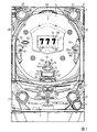
あるパチンコ遊技機1の全体の構成について説明する。図1はパチンコ遊技機1を正面か
らみた正面図である。
Hereinafter, the first embodiment of the present invention will be described with reference to the drawings. First, the overall configuration of the
パチンコ遊技機1は、縦長の方形状に形成された外枠(図示せず)と、外枠の内側に開
閉可能に取り付けられた遊技枠とで構成される。また、パチンコ遊技機1は、遊技枠に開
閉可能に設けられている額縁状に形成されたガラス扉枠2を有する。遊技枠は、外枠に対
して開閉自在に設置される前面枠(図示せず)と、機構部品等が取り付けられる機構板(
図示せず)と、それらに取り付けられる種々の部品(後述する遊技盤6を除く)とを含む
構造体である。
The
It is a structure including (not shown) and various parts (excluding the
ガラス扉枠2の下部表面には打球供給皿(上皿)3がある。打球供給皿3の下部には、
打球供給皿3に収容しきれない遊技球を貯留する余剰球受皿4や、打球を発射する打球操
作ハンドル(操作ノブ)5が設けられている。また、ガラス扉枠2の背面には、遊技盤6
が着脱可能に取り付けられている。なお、遊技盤6は、それを構成する板状体と、その板
状体に取り付けられた種々の部品とを含む構造体である。また、遊技盤6の前面には、打
ち込まれた遊技球が流下可能な遊技領域7が形成されている。
On the lower surface of the
A
Is detachably attached. The
余剰球受皿(下皿)4を形成する部材には、例えば下皿本体の上面における手前側の所
定位置(例えば下皿の中央部分)などに、スティック形状(棒形状)に構成され、遊技者
が把持して複数方向(前後左右)に傾倒操作が可能なスティックコントローラ122が取
り付けられている。なお、スティックコントローラ122には、遊技者がスティックコン
トローラ122の操作桿を操作手(例えば左手など)で把持した状態において、所定の操
作指(例えば人差し指など)で押引操作することなどにより所定の指示操作が可能なトリ
ガボタン121(図3を参照)が設けられ、スティックコントローラ122の操作桿の内
部には、トリガボタン121に対する押引操作などによる所定の指示操作を検知するトリ
ガセンサ125(図3を参照)が内蔵されている。また、スティックコントローラ122
の下部における下皿の本体内部などには、操作桿に対する傾倒操作を検知する傾倒方向セ
ンサユニット123(図3を参照)が設けられている。また、スティックコントローラ1
22には、スティックコントローラ122を振動動作させるためのバイブレータ用モータ
126(図3を参照)が内蔵されている。
The member forming the surplus ball saucer (lower plate) 4 is formed in a stick shape (bar shape) at a predetermined position on the front side (for example, the central portion of the lower plate) on the upper surface of the lower plate body, and the player
A tilting direction sensor unit 123 (see FIG. 3) for detecting a tilting operation on the operation stick is provided inside the main body of the lower plate at the lower part of the plate. Also,
The vibrator motor 126 (see FIG. 3) for vibrating the
打球供給皿(上皿)3を形成する部材には、例えば上皿本体の上面における手前側の所
定位置(例えばスティックコントローラ122の上方)などに、遊技者が押下操作などに
より所定の指示操作を可能なプッシュボタン120が設けられている。プッシュボタン1
20は、遊技者からの押下操作などによる所定の指示操作を、機械的、電気的、あるいは
、電磁的に、検出できるように構成されていればよい。プッシュボタン120の設置位置
における上皿の本体内部などには、プッシュボタン120に対してなされた遊技者の操作
行為を検知するプッシュセンサ124(図3を参照)が設けられていればよい。図1に示
す構成例では、プッシュボタン120とスティックコントローラ122の取付位置が、上
皿及び下皿の中央部分において上下の位置関係にある。これに対して、上下の位置関係を
保ったまま、プッシュボタン120及びスティックコントローラ122の取付位置を、上
皿及び下皿において左右のいずれかに寄せた位置としてもよい。あるいは、プッシュボタ
ン120とスティックコントローラ122の取付位置が上下の位置関係にはなく、例えば
左右の位置関係にあるものとしてもよい。
The member forming the hitting ball supply plate (upper plate) 3 is subjected to a predetermined instruction operation by a player, for example, at a predetermined position on the front side (for example, above the stick controller 122) on the upper surface of the upper plate main body. A
遊技領域7の中央付近には、液晶表示装置(LCD)で構成された演出表示装置9が設
けられている。演出表示装置9の表示画面には、第1特別図柄または第2特別図柄の可変
表示に同期した演出図柄の可変表示を行う演出図柄表示領域がある。よって、演出表示装
置9は、演出図柄の可変表示を行う可変表示装置に相当する。演出図柄表示領域には、例
えば「左」、「中」、「右」の3つの装飾用(演出用)の演出図柄を可変表示する図柄表
示エリアがある。図柄表示エリアには「左」、「中」、「右」の各図柄表示エリアがある
が、図柄表示エリアの位置は、演出表示装置9の表示画面において固定的でなくてもよい
し、図柄表示エリアの3つ領域が離れてもよい。演出表示装置9は、演出制御基板に搭載
されている演出制御用マイクロコンピュータによって制御される。演出制御用マイクロコ
ンピュータが、第1特別図柄表示器8aで第1特別図柄の可変表示が実行されているとき
に、その可変表示に伴って演出表示装置9で演出表示を実行させ、第2特別図柄表示器8
bで第2特別図柄の可変表示が実行されているときに、その可変表示に伴って演出表示装
置9で演出表示を実行させるので、遊技の進行状況を把握しやすくすることができる。
An
When the variable display of the second special symbol is being executed in b, the effect display is executed by the
また、演出表示装置9において、最終停止図柄(例えば左右中図柄のうち中図柄)とな
る図柄以外の図柄が、所定時間継続して、大当り図柄(例えば左中右の図柄が同じ図柄で
揃った図柄の組み合わせ)と一致している状態で停止、揺動、拡大縮小もしくは変形して
いる状態、または、複数の図柄が同一図柄で同期して変動したり、表示図柄の位置が入れ
替わっていたりして、最終結果が表示される前で大当り発生の可能性が継続している状態
(以下、これらの状態をリーチ状態という。)において行われる演出をリーチ演出という
。また、リーチ状態やその様子をリーチ態様という。さらに、リーチ演出を含む可変表示
をリーチ可変表示という。そして、演出表示装置9に変動表示される図柄の表示結果が大
当り図柄でない場合には「はずれ」となり、変動表示状態は終了する。遊技者は、大当り
をいかにして発生させるかを楽しみつつ遊技を行う。
Further, in the
演出表示装置9の表示画面の右上方部には、演出図柄と後述する特別図柄および普通図
柄とに次ぐ第4図柄を表示する第4図柄表示領域9c,9dが設けられている。この実施
の形態では、後述する第1特別図柄の変動表示に同期して第1特別図柄用の第4図柄の変
動表示が行われる第1特別図柄用の第4図柄表示領域9cと、第2特別図柄の変動表示に
同期して第2特別図柄用の第4図柄の変動表示が行われる第2特別図柄用の第4図柄表示
領域9dとが設けられている。
In the upper right portion of the display screen of the
なお、第1特別図柄用の第4図柄と第2特別図柄用の第4図柄とを、第4図柄と総称す
ることがあり、第1特別図柄用の第4図柄表示領域9cと第2特別図柄用の第4図柄表示
領域9dを、第4図柄表示領域と総称することがある。
The 4th symbol for the 1st special symbol and the 4th symbol for the 2nd special symbol may be collectively referred to as the 4th symbol, and the 4th
第4図柄の変動(可変表示)は、第4図柄表示領域9c,9dを所定の表示色(例えば
、青色)で一定の時間間隔で点灯と消灯とを繰り返す状態を継続することによって実現さ
れる。第1特別図柄表示器8aにおける第1特別図柄の可変表示と、第1特別図柄用の第
4図柄表示領域9cにおける第1特別図柄用の第4図柄の可変表示とは同期している。第
2特別図柄表示器8bにおける第2特別図柄の可変表示と、第2特別図柄用の第4図柄表
示領域9dにおける第2特別図柄用の第4図柄の可変表示とは同期している。同期とは、
可変表示の開始時点および終了時点が同じであって、可変表示の期間が同じであることを
いう。
The variation (variable display) of the fourth symbol is realized by continuing the state in which the fourth
It means that the start time and end time of the variable display are the same, and the period of the variable display is the same.
演出表示装置9の右方には、識別情報としての第1特別図柄を可変表示する第1特別図
柄表示器(第1可変表示部)8aが設けられている。この実施の形態では、第1特別図柄
表示器8aは、0〜9の数字を可変表示可能な簡易で小型の表示器(例えば7セグメント
LED)で実現されている。すなわち、第1特別図柄表示器8aは、0〜9の数字(また
は、記号)を可変表示するように構成されている。また、演出表示装置9の右方(第1特
別図柄表示器8aの右隣)には、識別情報としての第2特別図柄を可変表示する第2特別
図柄表示器(第2可変表示部)8bも設けられている。第2特別図柄表示器8bは、0〜
9の数字を可変表示可能な簡易で小型の表示器(例えば7セグメントLED)で実現され
ている。すなわち、第2特別図柄表示器8bは、0〜9の数字(または、記号)を可変表
示するように構成されている。
On the right side of the
It is realized by a simple and small display (for example, a 7-segment LED) capable of variably displaying the
小型の表示器は、例えば方形状に形成されている。また、この実施の形態では、第1特
別図柄の種類と第2特別図柄の種類とは同じ(例えば、ともに0〜9の数字)であるが、
種類が異なっていてもよい。また、第1特別図柄表示器8aおよび第2特別図柄表示器8
bは、それぞれ、例えば、00〜99の数字(または、2桁の記号)を可変表示するよう
に構成されていてもよい。
The small display is formed in a square shape, for example. Further, in this embodiment, the type of the first special symbol and the type of the second special symbol are the same (for example, both
The type may be different. In addition, the first
Each b may be configured to variably display, for example, a number (or a two-digit symbol) from 00 to 99.
以下、第1特別図柄と第2特別図柄とを特別図柄と総称することがあり、第1特別図柄
表示器8aと第2特別図柄表示器8bとを特別図柄表示器(可変表示部)と総称すること
がある。
Hereinafter, the first special symbol and the second special symbol may be collectively referred to as a special symbol, and the first
なお、この実施の形態では、2つの特別図柄表示器8a,8bを備える場合を示してい
るが、遊技機は、特別図柄表示器を1つのみ備えるものであってもよい。
Although this embodiment shows a case where two
第1特別図柄または第2特別図柄の可変表示は、可変表示の実行条件である第1始動条
件または第2始動条件が成立(例えば、遊技球が第1始動入賞口13または第2始動入賞
口14を通過(入賞を含む)したこと)した後、可変表示の開始条件(例えば、保留記憶
数が0でない場合であって、第1特別図柄および第2特別図柄の可変表示が実行されてい
ない状態であり、かつ、大当り遊技が実行されていない状態)が成立したことにもとづい
て開始され、可変表示時間(変動時間)が経過すると表示結果(停止図柄)を導出表示す
る。なお、遊技球が通過するとは、入賞口やゲートなどのあらかじめ入賞領域として定め
られている領域を遊技球が通過したことであり、入賞口に遊技球が入った(入賞した)こ
とを含む概念である。また、表示結果を導出表示するとは、図柄(識別情報の例)を最終
的に停止表示させることである。
In the variable display of the first special symbol or the second special symbol, the first start condition or the second start condition, which is the execution condition of the variable display, is satisfied (for example, the game ball has the first
演出表示装置9の下方には、第1始動入賞口13を有する入賞装置が設けられている。
第1始動入賞口13に入賞した遊技球は、遊技盤6の背面に導かれ、第1始動口スイッチ
13aによって検出される。
Below the
The game ball that has won the first
また、第1始動入賞口(第1始動口)13を有する入賞装置の下方には、遊技球が入賞
可能な第2始動入賞口14を有する可変入賞球装置15が設けられている。第2始動入賞
口(第2始動口)14に入賞した遊技球は、遊技盤6の背面に導かれ、第2始動口スイッ
チ14aによって検出される。可変入賞球装置15は、ソレノイド16によって開状態と
される。可変入賞球装置15が開状態になることによって、遊技球が第2始動入賞口14
に入賞可能になり(始動入賞し易くなり)、遊技者にとって有利な状態になる。可変入賞
球装置15が開状態になっている状態では、第1始動入賞口13よりも、第2始動入賞口
14に遊技球が入賞しやすい。また、可変入賞球装置15が閉状態になっている状態では
、遊技球は第2始動入賞口14に入賞しない。従って、可変入賞球装置15が閉状態にな
っている状態では、第2始動入賞口14よりも、第1始動入賞口13に遊技球が入賞しや
すい。なお、可変入賞球装置15が閉状態になっている状態において、入賞はしづらいも
のの、入賞することは可能である(すなわち、遊技球が入賞しにくい)ように構成されて
いてもよい。
Further, below the winning device having the first starting winning opening (first starting opening) 13, a variable winning
It becomes possible to win a prize (it becomes easier to win a starting prize), which is advantageous for the player. In the state where the variable winning
以下、第1始動入賞口13と第2始動入賞口14とを総称して始動入賞口または始動口
ということがある。
Hereinafter, the first
可変入賞球装置15が開放状態に制御されているときには可変入賞球装置15に向かう
遊技球は第2始動入賞口14に極めて入賞しやすい。そして、第1始動入賞口13は演出
表示装置9の直下に設けられているが、演出表示装置9の下端と第1始動入賞口13との
間の間隔をさらに狭めたり、第1始動入賞口13の周辺で釘を密に配置したり、第1始動
入賞口13の周辺での釘配列を遊技球を第1始動入賞口13に導きづらくして、第2始動
入賞口14の入賞率の方を第1始動入賞口13の入賞率よりもより高くするようにしても
よい。
When the variable winning
第2特別図柄表示器8bの上方には、第2始動入賞口14に入った有効入賞球数すなわ
ち第2保留記憶数を表示する4つの表示器からなる第2特別図柄保留記憶表示器18bが
設けられている。第2特別図柄保留記憶表示器18bは、有効始動入賞がある毎に、点灯
する表示器の数を1増やす。そして、第2特別図柄表示器8bでの可変表示が開始される
毎に、点灯する表示器の数を1減らす。
Above the second
また、第2特別図柄保留記憶表示器18bのさらに上方には、第1始動入賞口13に入
った有効入賞球数すなわち第1保留記憶数(保留記憶を、始動記憶または始動入賞記憶と
もいう。)を表示する4つの表示器からなる第1特別図柄保留記憶表示器18aが設けら
れている。第1特別図柄保留記憶表示器18aは、有効始動入賞がある毎に、点灯する表
示器の数を1増やす。そして、第1特別図柄表示器8aでの可変表示が開始される毎に、
点灯する表示器の数を1減らす。
Further, above the second special symbol hold storage display 18b, the number of effective winning balls that have entered the first
Reduce the number of lit indicators by 1.
また、演出表示装置9の表示画面には、第1保留記憶数を表示する第1保留記憶表示部
9aと、第2保留記憶数を表示する第2保留記憶表示部9bとが設けられている。なお、
この実施の形態で示した態様にかぎらず、例えば、第1保留記憶表示部9aと第2保留記
憶表示部9bとに代えて、第1保留記憶数と第2保留記憶数との合計である合計数(合算
保留記憶数)を表示する領域(合算保留記憶表示部)が設けられるように構成してもよい
。
Further, the display screen of the
Not limited to the embodiment shown in this embodiment, for example, instead of the first reserved
演出表示装置9は、第1特別図柄表示器8aによる第1特別図柄の可変表示時間中、お
よび第2特別図柄表示器8bによる第2特別図柄の可変表示時間中に、装飾用(演出用)
の図柄としての演出図柄の可変表示を行う。第1特別図柄表示器8aにおける第1特別図
柄の可変表示と、演出表示装置9における演出図柄の可変表示とは同期している。また、
第2特別図柄表示器8bにおける第2特別図柄の可変表示と、演出表示装置9における演
出図柄の可変表示とは同期している。また、第1特別図柄表示器8aにおいて大当り図柄
が停止表示されるときと、第2特別図柄表示器8bにおいて大当り図柄が停止表示される
ときには、演出表示装置9において大当りを想起させるような演出図柄の組み合わせが停
止表示される。
The
Variable display of the production symbol as the symbol of. The variable display of the first special symbol on the first
The variable display of the second special symbol on the second
また、図1に示すように、可変入賞球装置15の下方には、大入賞口を形成する特別可
変入賞球装置20が設けられている。特別可変入賞球装置20は開閉板を備え、第1特別
図柄表示器8aに特定表示結果(大当り図柄)が導出表示されたときと、第2特別図柄表
示器8bに特定表示結果(大当り図柄)が導出表示されたときに生起する特定遊技状態(
大当り遊技状態)においてソレノイド21によって開閉板が開放状態に制御されることに
よって、入賞領域となる大入賞口が開放状態になる。大入賞口に入賞した遊技球はカウン
トスイッチ23で検出される。
Further, as shown in FIG. 1, a special variable winning
In the big hit game state), the opening / closing plate is controlled to the open state by the
演出表示装置9の左方には、普通図柄を可変表示する普通図柄表示器10が設けられて
いる。この実施の形態では、普通図柄表示器10は、0〜9の数字を可変表示可能な簡易
で小型の表示器(例えば7セグメントLED)で実現されている。すなわち、普通図柄表
示器10は、0〜9の数字(または、記号)を可変表示するように構成されている。また
、小型の表示器は、例えば方形状に形成されている。なお、普通図柄表示器10は、例え
ば、00〜99の数字(または、2桁の記号)を可変表示するように構成されていてもよ
い。また、普通図柄表示器10は、7セグメントLEDなどにかぎらず、例えば、所定の
記号表示を点灯表示可能な表示器(例えば、「○」や「×」を交互に点灯表示可能な装飾
ランプ)で構成されていてもよい。
On the left side of the
遊技球がゲート32を通過しゲートスイッチ32aで検出されると、普通図柄表示器1
0の表示の可変表示が開始される。そして、普通図柄表示器10における停止図柄が所定
の図柄(当り図柄。例えば、図柄「7」。)である場合に、可変入賞球装置15が所定回
数、所定時間だけ開状態になる。すなわち、可変入賞球装置15の状態は、普通図柄の停
止図柄が当り図柄である場合に、遊技者にとって不利な状態から有利な状態(第2始動入
賞口14に遊技球が入賞可能な状態)に変化する。普通図柄表示器10の近傍には、ゲー
ト32を通過した入賞球数を表示する4つのLEDによる表示部を有する普通図柄保留記
憶表示器41が設けられている。ゲート32への遊技球の通過がある毎に、すなわちゲー
トスイッチ32aによって遊技球が検出される毎に、普通図柄保留記憶表示器41は点灯
するLEDを1増やす。そして、普通図柄表示器10の可変表示が開始される毎に、点灯
するLEDを1減らす。さらに、通常状態に比べて大当りとすることに決定される確率が
高い状態である確変状態(通常状態と比較して、特別図柄の変動表示結果として大当りと
判定される確率が高められた状態)では、普通図柄表示器10における停止図柄が当り図
柄になる確率が高められるとともに、可変入賞球装置15の開放時間と開放回数が高めら
れる。また、確変状態ではないが図柄の変動時間が短縮されている時短状態(特別図柄の
可変表示時間が短縮される遊技状態)でも、可変入賞球装置15の開放時間と開放回数が
高められる。
When the game ball passes through the
The variable display of the display of 0 is started. Then, when the stop symbol on the
遊技盤6の下部には、入賞しなかった打球が取り込まれるアウト口26がある。また、
遊技領域7の外側の左右上部および左右下部には、所定の音声出力として効果音や音声を
発声する4つのスピーカ27が設けられている。遊技領域7の外周には、前面枠に設けら
れた枠LED28が設けられている。
At the lower part of the
Four
遊技機には、遊技者が打球操作ハンドル5を操作することに応じて駆動モータを駆動し
、駆動モータの回転力を利用して遊技球を遊技領域7に発射する打球発射装置(図示せず
)が設けられている。打球発射装置から発射された遊技球は、遊技領域7を囲むように円
形状に形成された打球レールを通って遊技領域7に入り、その後、遊技領域7を下りてく
る。遊技球が第1始動入賞口13に入り第1始動口スイッチ13aで検出されると、第1
特別図柄の可変表示を開始できる状態であれば(例えば、特別図柄の可変表示が終了し、
第1の開始条件が成立したこと)、第1特別図柄表示器8aにおいて第1特別図柄の可変
表示(変動)が開始されるとともに、演出表示装置9において演出図柄の可変表示が開始
される。すなわち、第1特別図柄および演出図柄の可変表示は、第1始動入賞口13への
入賞に対応する。第1特別図柄の可変表示を開始できる状態でなければ、第1保留記憶数
が上限値に達していないことを条件として、第1保留記憶数を1増やす。
The game machine is a ball launching device (not shown) that drives a drive motor in response to the player operating the
If the variable display of the special symbol can be started (for example, the variable display of the special symbol ends,
(The first start condition is satisfied), the variable display (variation) of the first special symbol is started on the first
遊技球が第2始動入賞口14に入り第2始動口スイッチ14aで検出されると、第2特
別図柄の可変表示を開始できる状態であれば(例えば、特別図柄の可変表示が終了し、第
2の開始条件が成立したこと)、第2特別図柄表示器8bにおいて第2特別図柄の可変表
示(変動)が開始されるとともに、演出表示装置9において演出図柄の可変表示が開始さ
れる。すなわち、第2特別図柄および演出図柄の可変表示は、第2始動入賞口14への入
賞に対応する。第2特別図柄の可変表示を開始できる状態でなければ、第2保留記憶数が
上限値に達していないことを条件として、第2保留記憶数を1増やす。
When the game ball enters the second
この実施の形態では、確変大当りとなった場合には、遊技状態を高確率状態(確変状態
)に移行するとともに、遊技球が始動入賞しやすくなる(すなわち、特別図柄表示器8a
,8bや演出表示装置9における可変表示の実行条件が成立しやすくなる)ように制御さ
れた遊技状態である高ベース状態に移行(この実施の形態では、時短状態に移行)する。
また、遊技状態が時短状態に移行されたときも、高ベース状態に移行する。高ベース状態
である場合には、例えば、高ベース状態でない場合と比較して、可変入賞球装置15が開
状態となる頻度が高められたり、可変入賞球装置15が開状態となる時間が延長されたり
して、始動入賞しやすくなる。
In this embodiment, in the case of a probability variation jackpot, the game state is shifted to the high probability state (probability variation state), and the game ball is easily started and won a prize (that is, the
, 8b and the
Also, when the gaming state is changed to the time saving state, it is also changed to the high base state. In the high base state, for example, the frequency with which the variable winning
なお、可変入賞球装置15が開状態となる時間を延長する(開放延長状態ともいう)の
でなく、普通図柄表示器10における停止図柄が当り図柄になる確率が高められる普通図
柄確変状態に移行することによって、高ベース状態に移行してもよい。普通図柄表示器1
0における停止図柄が所定の図柄(当り図柄)となると、可変入賞球装置15が所定回数
、所定時間だけ開状態になる。この場合、普通図柄確変状態に移行制御することによって
、普通図柄表示器10における停止図柄が当り図柄になる確率が高められ、可変入賞球装
置15が開状態となる頻度が高まる。従って、普通図柄確変状態に移行すれば、可変入賞
球装置15の開放時間と開放回数が高められ、始動入賞しやすい状態(高ベース状態)と
なる。すなわち、可変入賞球装置15の開放時間と開放回数は、普通図柄の停止図柄が当
り図柄であったり、特別図柄の停止図柄が確変図柄である場合等に高められ、遊技者にと
って不利な状態から有利な状態(始動入賞しやすい状態)に変化する。なお、開放回数が
高められることは、閉状態から開状態になることも含む概念である。
In addition, instead of extending the time during which the variable winning
When the stop symbol at 0 becomes a predetermined symbol (hit symbol), the variable winning
また、普通図柄表示器10における普通図柄の変動時間(可変表示期間)が短縮される
普通図柄時短状態に移行することによって、高ベース状態に移行してもよい。普通図柄時
短状態では、普通図柄の変動時間が短縮されるので、普通図柄の変動が開始される頻度が
高くなり、結果として普通図柄が当りとなる頻度が高くなる。従って、普通図柄が当たり
となる頻度が高くなることによって、可変入賞球装置15が開状態となる頻度が高くなり
、始動入賞しやすい状態(高ベース状態)となる。
Further, the
また、特別図柄や演出図柄の変動時間(可変表示期間)が短縮される時短状態に移行す
ることによって、特別図柄や演出図柄の変動時間が短縮されるので、特別図柄や演出図柄
の変動が開始される頻度が高くなり(換言すれば、保留記憶の消化が速くなる。)、無効
な始動入賞が生じてしまう事態を低減することができる。従って、有効な始動入賞が発生
しやすくなり、結果として、大当り遊技が行われる可能性が高まる。
In addition, by shifting to a time-saving state in which the fluctuation time (variable display period) of the special symbol or the effect symbol is shortened, the fluctuation time of the special symbol or the effect symbol is shortened, so that the fluctuation of the special symbol or the effect symbol starts. The frequency of this is increased (in other words, the pending memory is digested faster), and it is possible to reduce the situation where an invalid start prize is generated. Therefore, a valid start prize is likely to occur, and as a result, the possibility of a big hit game is increased.
さらに、上記に示した全ての状態(開放延長状態、普通図柄確変状態、普通図柄時短状
態および特別図柄時短状態)に移行させることによって、始動入賞しやすくなる(高ベー
ス状態に移行する)ようにしてもよい。また、上記に示した各状態(開放延長状態、普通
図柄確変状態、普通図柄時短状態および特別図柄時短状態)のうちのいずれか複数の状態
に移行させることによって、始動入賞しやすくなる(高ベース状態に移行する)ようにし
てもよい。また、上記に示した各状態(開放延長状態、普通図柄確変状態、普通図柄時短
状態および特別図柄時短状態)のうちのいずれか1つの状態にのみ移行させることによっ
て、始動入賞しやすくなる(高ベース状態に移行する)ようにしてもよい。
Furthermore, by shifting to all the states shown above (open extension state, normal symbol probability change state, normal symbol time reduction state and special symbol time reduction state), it becomes easier to win a starting prize (shift to a high base state). You may. In addition, by shifting to any one or more of the above-mentioned states (open extension state, normal symbol probability change state, normal symbol time reduction state, and special symbol time reduction state), it becomes easier to win a start prize (high base). It may be changed to the state). In addition, by shifting to only one of the above-mentioned states (open extension state, normal symbol probability change state, normal symbol time reduction state, and special symbol time reduction state), it becomes easier to win a start prize (high). It may move to the base state).
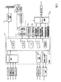
図2は、主基板(遊技制御基板)31における回路構成の一例を示すブロック図である
。なお、図2は、払出制御基板37および演出制御基板80等も示されている。主基板3
1には、プログラムに従ってパチンコ遊技機1を制御する遊技制御用マイクロコンピュー
タ(遊技制御手段に相当)560が搭載されている。遊技制御用マイクロコンピュータ5
60は、ゲーム制御(遊技進行制御)用のプログラム等を記憶するROM54、ワークメ
モリとして使用される記憶手段としてのRAM55、プログラムに従って制御動作を行う
CPU56およびI/Oポート部57を含む。この実施の形態では、ROM54およびR
AM55は遊技制御用マイクロコンピュータ560に内蔵されている。すなわち、遊技制
御用マイクロコンピュータ560は、1チップマイクロコンピュータである。1チップマ
イクロコンピュータには、少なくともCPU56のほかRAM55が内蔵されていればよ
く、ROM54は外付けであっても内蔵されていてもよい。また、I/Oポート部57は
、外付けであってもよい。遊技制御用マイクロコンピュータ560には、さらに、ハード
ウェア乱数(ハードウェア回路が発生する乱数)を発生する乱数回路503が内蔵されて
いる。
FIG. 2 is a block diagram showing an example of a circuit configuration on the main board (game control board) 31. Note that FIG. 2 also shows a
1 is equipped with a game control microcomputer (corresponding to a game control means) 560 that controls the
The
また、RAM55は、その一部または全部が電源基板において作成されるバックアップ
電源によってバックアップされている不揮発性記憶手段としてのバックアップRAMであ
る。すなわち、遊技機に対する電力供給が停止しても、所定のバックアップ期間(バック
アップ電源としてのコンデンサが放電してバックアップ電源が電力供給不能になるまで)
は、RAM55の一部または全部の内容は保存される。特に、少なくとも、遊技状態すな
わち遊技制御手段の制御状態に応じたデータ(特別図柄プロセスフラグや、確変フラグな
ど)と未払出賞球数を示すデータは、バックアップRAMに保存される。遊技制御手段の
制御状態に応じたデータとは、停電等が生じた後に復旧した場合に、そのデータにもとづ
いて、制御状態を停電等の発生前に復旧させるために必要なデータである。また、制御状
態に応じたデータと未払出賞球数を示すデータとを遊技の進行状態を示すデータと定義す
る。なお、この実施の形態では、RAM55の全部が、電源バックアップされているとす
る。
Further, the
Is stored in part or all of the contents of the
なお、遊技制御用マイクロコンピュータ560においてCPU56がROM54に格納
されているプログラムに従って制御を実行するので、以下、遊技制御用マイクロコンピュ
ータ560(またはCPU56)が実行する(または、処理を行う)ということは、具体
的には、CPU56がプログラムに従って制御を実行することである。このことは、主基
板31以外の他の基板に搭載されているマイクロコンピュータについても同様である。
Since the
乱数回路503は、特別図柄の可変表示の表示結果により大当りとするか否か判定する
ための判定用の乱数を発生するために用いられるハードウェア回路である。乱数回路50
3は、初期値(例えば、0)と上限値(例えば、65535)とが設定された数値範囲内
で、数値データを、設定された更新規則に従って更新し、ランダムなタイミングで発生す
る始動入賞時が数値データの読出(抽出)時であることにもとづいて、読出される数値デ
ータが乱数値となる乱数発生機能を有する。
The random number circuit 503 is a hardware circuit used to generate a random number for determination for determining whether or not to make a big hit based on the display result of the variable display of the special symbol.
In 3, the numerical data is updated according to the set update rule within the numerical range in which the initial value (for example, 0) and the upper limit value (for example, 65535) are set, and the starting prize is generated at a random timing. Has a random number generation function in which the read numerical data becomes a random number value based on the time when the numerical data is read (extracted).
また、ゲートスイッチ32a、第1始動口スイッチ13a、第2始動口スイッチ14a
、カウントスイッチ23からの検出信号を遊技制御用マイクロコンピュータ560に与え
る入力ドライバ回路58も主基板31に搭載されている。また、可変入賞球装置15を開
閉するソレノイド16、および大入賞口を形成する特別可変入賞球装置20を開閉するソ
レノイド21を遊技制御用マイクロコンピュータ560からの指令に従って駆動する出力
回路59も主基板31に搭載されている。
Further, the
The
また、遊技制御用マイクロコンピュータ560は、特別図柄を可変表示する第1特別図
柄表示器8a、第2特別図柄表示器8b、普通図柄を可変表示する普通図柄表示器10、
第1特別図柄保留記憶表示器18a、第2特別図柄保留記憶表示器18bおよび普通図柄
保留記憶表示器41の表示制御を行う。
Further, the
The display control of the first special symbol holding
なお、大当り遊技状態の発生を示す大当り情報等の情報出力信号を、ターミナル基板1
60を介して、ホールコンピュータ等の外部装置に対して出力する情報出力回路64も主
基板31に搭載されている。
It should be noted that the
The information output circuit 64 that outputs to an external device such as a hall computer via the 60 is also mounted on the main board 31.
この実施の形態では、演出制御基板80に搭載されている演出制御手段(演出制御用マ
イクロコンピュータで構成される。)が、中継基板77を介して遊技制御用マイクロコン
ピュータ560から演出内容を指示する演出制御コマンドを受信し、演出図柄を可変表示
する演出表示装置9の表示制御を行う。
In this embodiment, the effect control means (consisting of the effect control microcomputer) mounted on the
また、演出制御基板80に搭載されている演出制御手段が、ランプドライバ基板35を
介して、枠側に設けられている枠LED28の表示制御を行うとともに、音声出力基板7
0を介してスピーカ27からの音出力の制御を行う。
Further, the effect control means mounted on the
The sound output from the
なお、演出制御手段には、後述するように、スティックコントローラ122が備えるト
リガセンサ125や傾倒方向センサユニット123、バイブレータ用モータ126、およ
びプッシュボタン120が備えるプッシュセンサ124にも接続されているのであるが(
図3参照)、図2では図示を省略している。
As will be described later, the effect control means is also connected to the
(See FIG. 3), not shown in FIG.
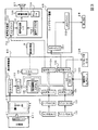
図3は、中継基板77、演出制御基板80、ランプドライバ基板35および音声出力基
板70の回路構成例を示すブロック図である。なお、図3に示す例では、ランプドライバ
基板35および音声出力基板70には、マイクロコンピュータは搭載されていないが、マ
イクロコンピュータを搭載してもよい。また、ランプドライバ基板35および音声出力基
板70を設けずに、演出制御に関して演出制御基板80のみを設けてもよい。
FIG. 3 is a block diagram showing a circuit configuration example of the relay board 77, the
演出制御基板80は、演出制御用CPU101、および演出図柄プロセスフラグ等の演
出に関する情報を記憶するRAMを含む演出制御用マイクロコンピュータ100を搭載し
ている。なお、RAMは外付けであってもよい。この実施の形態では、演出制御用マイク
ロコンピュータ100におけるRAMは電源バックアップされていない。演出制御基板8
0において、演出制御用CPU101は、内蔵または外付けのROM(図示せず)に格納
されたプログラムに従って動作し、中継基板77を介して入力される主基板31からの取
込信号(演出制御INT信号)に応じて、入力ドライバ102および入力ポート103を
介して演出制御コマンドを受信する。また、演出制御用CPU101は、演出制御コマン
ドにもとづいて、VDP(ビデオディスプレイプロセッサ)109に演出表示装置9の表
示制御を行わせる。
The
At 0, the
この実施の形態では、演出制御用マイクロコンピュータ100と共動して演出表示装置
9の表示制御を行うVDP109が演出制御基板80に搭載されている。VDP109は
、演出制御用マイクロコンピュータ100とは独立したアドレス空間を有し、そこにVR
AMをマッピングする。VRAMは、画像データを展開するためのバッファメモリである
。そして、VDP109は、VRAM内の画像データをフレームメモリを介して演出表示
装置9に出力する。
In this embodiment, a
Map AM. VRAM is a buffer memory for expanding image data. Then, the
演出制御用CPU101は、受信した演出制御コマンドに従ってCGROM(図示せず
)から必要なデータを読み出すための指令をVDP109に出力する。CGROMは、演
出表示装置9に表示されるキャラクタ画像データや動画像データ、具体的には、人物、文
字、図形や記号等(演出図柄を含む)、および背景画像のデータをあらかじめ格納してお
くためのROMである。VDP109は、演出制御用CPU101の指令に応じて、CG
ROMから画像データを読み出す。そして、VDP109は、読み出した画像データにも
とづいて表示制御を実行する。
The
Read image data from ROM. Then, the
演出制御コマンドおよび演出制御INT信号は、演出制御基板80において、まず、入
力ドライバ102に入力する。入力ドライバ102は、中継基板77から入力された信号
を演出制御基板80の内部に向かう方向にしか通過させない(演出制御基板80の内部か
ら中継基板77への方向には信号を通過させない)信号方向規制手段としての単方向性回
路でもある。
The effect control command and the effect control INT signal are first input to the
中継基板77には、主基板31から入力された信号を演出制御基板80に向かう方向に
しか通過させない(演出制御基板80から中継基板77への方向には信号を通過させない
)信号方向規制手段としての単方向性回路74が搭載されている。単方向性回路として、
例えばダイオードやトランジスタが使用される。図3には、ダイオードが例示されている
。また、単方向性回路は、各信号毎に設けられる。さらに、単方向性回路である出力ポー
ト571を介して主基板31から演出制御コマンドおよび演出制御INT信号が出力され
るので、中継基板77から主基板31の内部に向かう信号が規制される。すなわち、中継
基板77からの信号は主基板31の内部(遊技制御用マイクロコンピュータ560側)に
入り込まない。なお、出力ポート571は、図2に示されたI/Oポート部57の一部で
ある。また、出力ポート571の外側(中継基板77側)に、さらに、単方向性回路であ
る信号ドライバ回路が設けられていてもよい。
As a signal direction regulating means, the relay board 77 allows the signal input from the main board 31 to pass only in the direction toward the effect control board 80 (the signal does not pass in the direction from the
For example, diodes and transistors are used. FIG. 3 illustrates a diode. Further, a unidirectional circuit is provided for each signal. Further, since the effect control command and the effect control INT signal are output from the main board 31 via the
また、演出制御用CPU101は、スティックコントローラ122のトリガボタン12
1に対する遊技者の操作行為を検出したことを示す情報信号としての操作検出信号を、ト
リガセンサ125から、入力ポート106を介して入力する。また、演出制御用CPU1
01は、プッシュボタン120に対する遊技者の操作行為を検出したことを示す情報信号
としての操作検出信号を、プッシュセンサ124から、入力ポート106を介して入力す
る。また、演出制御用CPU101は、スティックコントローラ122の操作桿に対する
遊技者の操作行為を検出したことを示す情報信号としての操作検出信号を、傾倒方向セン
サユニット123から、入力ポート106を介して入力する。また、演出制御用CPU1
01は、出力ポート105を介してバイブレータ用モータ126に駆動信号を出力するこ
とにより、スティックコントローラ122を振動動作させる。
Further, the
An operation detection signal as an information signal indicating that the player's operation action with respect to 1 has been detected is input from the
01 inputs an operation detection signal as an information signal indicating that the player's operation action on the
01 vibrates the
さらに、演出制御用CPU101は、出力ポート105を介してランプドライバ基板3
5に対してLEDを駆動する信号を出力する。また、演出制御用CPU101は、出力ポ
ート104を介して音声出力基板70に対して音番号データを出力する。
Further, the
A signal for driving the LED is output for 5. Further, the
ランプドライバ基板35において、LEDを駆動する信号は、入力ドライバ351を介
してLEDドライバ352に入力される。LEDドライバ352は、LEDを駆動する信
号にもとづいて枠LED28などの発光体に電流を供給する。
In the
音声出力基板70において、音番号データは、入力ドライバ702を介して音声合成用
IC703に入力される。音声合成用IC703は、音番号データに応じた音声や効果音
を発生し増幅回路705に出力する。増幅回路705は、音声合成用IC703の出力レ
ベルを、ボリューム706で設定されている音量に応じたレベルに増幅した音声信号をス
ピーカ27に出力する。音声データROM704には、音番号データに応じた制御データ
が格納されている。音番号データに応じた制御データは、所定の演出期間(例えば演出図
柄の変動期間)における効果音または音声の出力態様を時系列的に示すデータの集まりで
ある。
In the
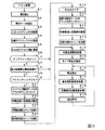
次に、遊技機の動作について説明する。図4は、主基板31における遊技制御用マイク
ロコンピュータ560が実行するメイン処理を示すフローチャートである。遊技機に対し
て電源が投入され電力供給が開始されると、リセット信号が入力されるリセット端子の入
力レベルがハイレベルになり、遊技制御用マイクロコンピュータ560(具体的には、C
PU56)は、プログラムの内容が正当か否か確認するための処理であるセキュリティチ
ェック処理を実行した後、ステップS1以降のメイン処理を開始する。メイン処理におい
て、CPU56は、まず、必要な初期設定を行う。
Next, the operation of the game machine will be described. FIG. 4 is a flowchart showing a main process executed by the
The PU56) starts the main process after step S1 after executing the security check process which is a process for confirming whether the content of the program is valid or not. In the main process, the
初期設定処理において、CPU56は、まず、割込禁止に設定する(ステップS1)。
次に、割込モードを割込モード2に設定し(ステップS2)、スタックポインタにスタッ
クポインタ指定アドレスを設定する(ステップS3)。そして、内蔵デバイスの初期化(
内蔵デバイス(内蔵周辺回路)であるCTC(カウンタ/タイマ)およびPIO(パラレ
ル入出力ポート)の初期化など)を行った後(ステップS4)、RAMをアクセス可能状
態に設定する(ステップS5)。なお、割込モード2は、CPU56が内蔵する特定レジ
スタ(Iレジスタ)の値(1バイト)と内蔵デバイスが出力する割込ベクタ(1バイト:
最下位ビット0)とから合成されるアドレスが、割込番地を示すモードである。
In the initial setting process, the
Next, the interrupt mode is set to the interrupt mode 2 (step S2), and the stack pointer designated address is set in the stack pointer (step S3). And initialization of the built-in device (
After performing CTC (counter / timer) and PIO (parallel input / output port) initialization, which are built-in devices (built-in peripheral circuits) (step S4), the RAM is set to an accessible state (step S5). In the interrupt
The address synthesized from the least significant bit 0) is the mode indicating the interrupt address.
次いで、CPU56は、入力ポートを介して入力されるクリアスイッチ(例えば、電源
基板に搭載されている。)の出力信号(クリア信号)の状態を確認する(ステップS6)
。その確認においてオンを検出した場合には、CPU56は、通常の初期化処理(ステッ
プS10〜S15)を実行する。
Next, the
.. When the ON is detected in the confirmation, the
クリアスイッチがオンの状態でない場合には、遊技機への電力供給が停止したときにバ
ックアップRAM領域のデータ保護処理(例えばパリティデータの付加等の電力供給停止
時処理)が行われたか否か確認する(ステップS7)。そのような保護処理が行われてい
ないことを確認したら、CPU56は初期化処理を実行する。バックアップRAM領域に
バックアップデータがあるか否かは、例えば、電力供給停止時処理においてバックアップ
RAM領域に設定されるバックアップフラグの状態によって確認される。
If the clear switch is not on, check whether data protection processing in the backup RAM area (for example, processing when power supply is stopped, such as addition of parity data) was performed when power supply to the game machine was stopped. (Step S7). After confirming that such protection processing has not been performed, the
電力供給停止時処理が行われたことを確認したら、CPU56は、バックアップRAM
領域のデータチェックを行う(ステップS8)。この実施の形態では、データチェックと
してパリティチェックを行う。よって、ステップS8では、算出したチェックサムと、電
力供給停止時処理で同一の処理によって算出され保存されているチェックサムとを比較す
る。不測の停電等の電力供給停止が生じた後に復旧した場合には、バックアップRAM領
域のデータは保存されているはずであるから、チェック結果(比較結果)は正常(一致)
になる。チェック結果が正常でないということは、バックアップRAM領域のデータが、
電力供給停止時のデータとは異なっていることを意味する。そのような場合には、内部状
態を電力供給停止時の状態に戻すことができないので、電力供給の停止からの復旧時でな
い電源投入時に実行される初期化処理を実行する。
After confirming that the power supply stop processing has been performed, the
The data of the area is checked (step S8). In this embodiment, a parity check is performed as a data check. Therefore, in step S8, the calculated checksum is compared with the checksum calculated and saved by the same processing in the power supply stop processing. If the data is restored after a power supply stop such as an unexpected power failure, the data in the backup RAM area should have been saved, so the check result (comparison result) is normal (match).
become. If the check result is not normal, the data in the backup RAM area is
It means that it is different from the data when the power supply is stopped. In such a case, since the internal state cannot be returned to the state when the power supply is stopped, the initialization process executed when the power is turned on, which is not the time when the power supply is stopped, is executed.
チェック結果が正常であれば、CPU56は、遊技制御手段の内部状態と演出制御手段
等の電気部品制御手段の制御状態を電力供給停止時の状態に戻すための遊技状態復旧処理
(ステップS41〜S43の処理)を行う。具体的には、ROM54に格納されているバ
ックアップ時設定テーブルの先頭アドレスをポインタに設定し(ステップS41)、バッ
クアップ時設定テーブルの内容を順次作業領域(RAM55内の領域)に設定する(ステ
ップS42)。作業領域はバックアップ電源によって電源バックアップされている。バッ
クアップ時設定テーブルには、作業領域のうち初期化してもよい領域についての初期化デ
ータが設定されている。ステップS41およびS42の処理によって、作業領域のうち初
期化してはならない部分については、保存されていた内容がそのまま残る。初期化しては
ならない部分とは、例えば、電力供給停止前の遊技状態を示すデータ(特別図柄プロセス
フラグ、確変フラグ、時短フラグなど)、出力ポートの出力状態が保存されている領域(
出力ポートバッファ)、未払出賞球数を示すデータが設定されている部分などである。
If the check result is normal, the
Output port buffer), the part where the data indicating the number of unpaid prize balls is set, etc.
また、CPU56は、電力供給復旧時の初期化コマンドとしての停電復旧指定コマンド
を送信する(ステップS43)。また、CPU56は、バックアップRAMに保存されて
いる表示結果(通常大当り、確変大当り、突然確変大当り、小当り、またははずれ)を指
定した表示結果指定コマンドを演出制御基板80に対して送信する(ステップS44)。
そして、ステップS14に移行する。なお、ステップS44において、CPU56は、例
えば、後述する特別図柄ポインタの値もバックアップRAMに保存している場合には、第
1図柄変動指定コマンドや第2図柄変動指定コマンド(図13参照)も送信するようにし
てもよい。この場合、演出制御用マイクロコンピュータ100は、第1図柄変動指定コマ
ンドや第2図柄変動指定コマンドを受信したことにもとづいて、第4図柄の変動表示を再
開するようにしてもよい。
Further, the
Then, the process proceeds to step S14. In step S44, for example, when the value of the special symbol pointer described later is also stored in the backup RAM, the
なお、この実施の形態では、バックアップRAM領域には、後述する変動時間タイマの
値も保存される。従って、停電復旧した場合には、ステップS44で表示結果指定コマン
ドが送信された後、保存していた変動時間タイマの値の計測を再開して特別図柄の変動表
示が再開されるとともに、保存していた変動時間タイマの値がタイムアウトしたときに、
さらに後述する図柄確定指定コマンドが送信される。また、この実施の形態では、バック
アップRAM領域には、後述する特別図柄プロセスフラグの値も保存される。従って、停
電復旧した場合には、保存されている特別図柄プロセスフラグの値に応じたプロセスから
特別図柄プロセス処理が再開される。
In this embodiment, the value of the variable time timer, which will be described later, is also stored in the backup RAM area. Therefore, when the power failure is restored, after the display result designation command is transmitted in step S44, the measurement of the value of the saved fluctuation time timer is restarted, the fluctuation display of the special symbol is restarted, and the data is saved. When the value of the variable time timer that was being timed out timed out
Furthermore, the symbol confirmation specification command described later is transmitted. Further, in this embodiment, the value of the special symbol process flag described later is also stored in the backup RAM area. Therefore, when the power failure is restored, the special symbol process processing is restarted from the process corresponding to the value of the saved special symbol process flag.
なお、停電復旧時に必ず表示結果指定コマンドを送信するのではなく、CPU56は、
まず、バックアップRAM領域に保存している変動時間タイマの値が0であるか否かを確
認するようにしてもよい。そして、変動時間タイマの値が0でなければ、変動中に停電し
た場合であると判断して、表示結果指定コマンドを送信するようにし、変動時間タイマが
0であれば、停電時に変動中の状態ではなかったと判断して、表示結果指定コマンドを送
信しないようにしてもよい。
It should be noted that the
First, it may be confirmed whether or not the value of the fluctuation time timer stored in the backup RAM area is 0. Then, if the value of the fluctuation time timer is not 0, it is determined that a power failure occurs during the fluctuation, and a display result specification command is transmitted. If the fluctuation time timer is 0, the fluctuation time occurs during the power failure. It may be determined that the state is not present and the display result specification command may not be sent.
また、CPU56は、まず、バックアップRAM領域に保存している特別図柄プロセス
フラグの値が3であるか否かを確認するようにしてもよい。そして、特別図柄プロセスフ
ラグの値が3であれば、変動中に停電した場合であると判断して、表示結果指定コマンド
を送信するようにし、特別図柄プロセスフラグが3でなければ、停電時に変動中ではなか
ったと判断して、表示結果指定コマンドを送信しないようにしてもよい。
Further, the
なお、この実施の形態では、バックアップフラグとチェックデータとの双方を用いてバ
ックアップRAM領域のデータが保存されているか否か確認しているが、いずれか一方の
みを用いてもよい。すなわち、バックアップフラグとチェックデータとのいずれかを、遊
技状態復旧処理を実行するための契機としてもよい。
In this embodiment, it is confirmed whether or not the data in the backup RAM area is stored by using both the backup flag and the check data, but only one of them may be used. That is, either the backup flag or the check data may be used as an opportunity to execute the game state recovery process.
初期化処理では、CPU56は、まず、RAMクリア処理を行う(ステップS10)。
なお、RAMクリア処理によって、所定のデータ(例えば、普通図柄当り判定用乱数を生
成するためのカウンタのカウント値のデータ)は0に初期化されるが、任意の値またはあ
らかじめ決められている値に初期化するようにしてもよい。また、RAM55の全領域を
初期化せず、所定のデータ(例えば、普通図柄当り判定用乱数を生成するためのカウンタ
のカウント値のデータ)をそのままにしてもよい。また、ROM54に格納されている初
期化時設定テーブルの先頭アドレスをポインタに設定し(ステップS11)、初期化時設
定テーブルの内容を順次作業領域に設定する(ステップS12)。
In the initialization process, the
By the RAM clear processing, predetermined data (for example, data of the count value of the counter for generating a random number for determining a normal symbol hit) is initialized to 0, but is an arbitrary value or a predetermined value. It may be initialized to. Further, the entire area of the
ステップS11およびS12の処理によって、例えば、普通図柄当り判定用乱数カウン
タ、特別図柄バッファ、総賞球数格納バッファ、特別図柄プロセスフラグなど制御状態に
応じて選択的に処理を行うためのフラグに初期値が設定される。
By the processing of steps S11 and S12, for example, a random number counter for determining a normal symbol hit, a special symbol buffer, a total prize ball number storage buffer, a special symbol process flag, and other flags for selectively processing according to the control state are initially set. The value is set.
また、CPU56は、サブ基板(主基板31以外のマイクロコンピュータが搭載された
基板。)を初期化するための初期化指定コマンド(遊技制御用マイクロコンピュータ56
0が初期化処理を実行したことを示すコマンドでもある。)をサブ基板に送信する(ステ
ップS13)。例えば、演出制御用マイクロコンピュータ100は、初期化指定コマンド
を受信すると、演出表示装置9において、遊技機の制御の初期化がなされたことを報知す
るための画面表示、すなわち初期化報知を行う。
Further, the
It is also a command indicating that 0 has executed the initialization process. ) Is transmitted to the sub-board (step S13). For example, when the
また、CPU56は、乱数回路503を初期設定する乱数回路設定処理を実行する(ス
テップS14)。CPU56は、例えば、乱数回路設定プログラムに従って処理を実行す
ることによって、乱数回路503にランダムRの値を更新させるための設定を行う。
Further, the
そして、ステップS15において、CPU56は、所定時間(例えば4ms)毎に定期
的にタイマ割込がかかるように遊技制御用マイクロコンピュータ560に内蔵されている
CTCのレジスタの設定を行なう。すなわち、初期値として例えば4msに相当する値が
所定のレジスタ(時間定数レジスタ)に設定される。この実施の形態では、4ms毎に定
期的にタイマ割込がかかるとする。
Then, in step S15, the
初期化処理の実行(ステップS10〜S15)が完了すると、CPU56は、メイン処
理で、表示用乱数更新処理(ステップS17)および初期値用乱数更新処理(ステップS
18)を繰り返し実行する。表示用乱数更新処理および初期値用乱数更新処理を実行する
ときには割込禁止状態に設定し(ステップS16)、表示用乱数更新処理および初期値用
乱数更新処理の実行が終了すると割込許可状態に設定する(ステップS19)。この実施
の形態では、表示用乱数とは、大当りとしない場合の特別図柄の停止図柄を決定するため
の乱数や大当りとしない場合にリーチとするか否かを決定するための乱数であり、表示用
乱数更新処理とは、表示用乱数を発生するためのカウンタのカウント値を更新する処理で
ある。また、初期値用乱数更新処理とは、初期値用乱数を発生するためのカウンタのカウ
ント値を更新する処理である。この実施の形態では、初期値用乱数とは、普通図柄に関し
て当りとするか否か決定するための乱数を発生するためのカウンタ(普通図柄当り判定用
乱数発生カウンタ)のカウント値の初期値を決定するための乱数である。後述する遊技の
進行を制御する遊技制御処理(遊技制御用マイクロコンピュータ560が、遊技機に設け
られている演出表示装置、可変入賞球装置、球払出装置等の遊技用の装置を、自身で制御
する処理、または他のマイクロコンピュータに制御させるために指令信号を送信する処理
、遊技装置制御処理ともいう)において、普通図柄当り判定用乱数のカウント値が1周(
普通図柄当り判定用乱数の取りうる値の最小値から最大値までの間の数値の個数分歩進し
たこと)すると、そのカウンタに初期値が設定される。
When the execution of the initialization process (steps S10 to S15) is completed, the
18) is repeatedly executed. When executing the display random number update process and the initial value random number update process, the interrupt prohibition state is set (step S16), and when the execution of the display random number update process and the initial value random number update process is completed, the interrupt enable state is set. Set (step S19). In this embodiment, the display random number is a random number for determining the stop symbol of the special symbol when it is not a big hit, or a random number for determining whether or not to reach when it is not a big hit, and it is displayed. The random number update process is a process of updating the count value of the counter for generating a random number for display. The initial value random number update process is a process of updating the count value of the counter for generating the initial value random number. In this embodiment, the initial value random number is the initial value of the count value of the counter for generating a random number for determining whether or not to hit the normal symbol (normal symbol hit determination random number generation counter). It is a random number to determine. Game control processing that controls the progress of the game, which will be described later (the
The initial value is set in the counter when the step is taken by the number of numerical values between the minimum value and the maximum value of the random number for normal symbol hit determination.
タイマ割込が発生すると、CPU56は、図5に示すステップS20〜S34のタイマ
割込処理を実行する。タイマ割込処理において、まず、電源断信号が出力されたか否か(
オン状態になったか否か)を検出する電源断検出処理を実行する(ステップS20)。電
源断信号は、例えば電源基板に搭載されている電源監視回路が、遊技機に供給される電源
の電圧の低下を検出した場合に出力する。そして、電源断検出処理において、CPU56
は、電源断信号が出力されたことを検出したら、必要なデータをバックアップRAM領域
に保存するための電力供給停止時処理を実行する。次いで、入力ドライバ回路58を介し
て、ゲートスイッチ32a、第1始動口スイッチ13a、第2始動口スイッチ14aおよ
びカウントスイッチ23の検出信号を入力し、それらの状態判定を行う(スイッチ処理:
ステップS21)。
When the timer interrupt occurs, the
A power failure detection process for detecting (whether or not it has been turned on) is executed (step S20). The power off signal is output when, for example, the power supply monitoring circuit mounted on the power supply board detects a decrease in the voltage of the power supply supplied to the game machine. Then, in the power failure detection process, the
When it detects that a power failure signal has been output, it executes a power supply stop processing for saving necessary data in the backup RAM area. Next, the detection signals of the
Step S21).
次に、CPU56は、第1特別図柄表示器8a、第2特別図柄表示器8b、普通図柄表
示器10、第1特別図柄保留記憶表示器18a、第2特別図柄保留記憶表示器18b、普
通図柄保留記憶表示器41の表示制御を行う表示制御処理を実行する(ステップS22)
。第1特別図柄表示器8a、第2特別図柄表示器8bおよび普通図柄表示器10について
は、ステップS32,S33で設定される出力バッファの内容に応じて各表示器に対して
駆動信号を出力する制御を実行する。
Next, the
.. For the first
また、遊技制御に用いられる普通図柄当り判定用乱数等の各判定用乱数を生成するため
の各カウンタのカウント値を更新する処理を行う(判定用乱数更新処理:ステップS23
)。CPU56は、さらに、初期値用乱数および表示用乱数を生成するためのカウンタの
カウント値を更新する処理を行う(初期値用乱数更新処理,表示用乱数更新処理:ステッ
プS24,S25)。
In addition, a process of updating the count value of each counter for generating each determination random number such as a normal symbol hit determination random number used for game control is performed (determination random number update process: step S23).
). The
さらに、CPU56は、特別図柄プロセス処理を行う(ステップS26)。特別図柄プ
ロセス処理では、第1特別図柄表示器8a、第2特別図柄表示器8bおよび大入賞口を所
定の順序で制御するための特別図柄プロセスフラグに従って該当する処理を実行する。C
PU56は、特別図柄プロセスフラグの値を、遊技状態に応じて更新する。
Further, the
The
次いで、普通図柄プロセス処理を行う(ステップS27)。普通図柄プロセス処理では
、CPU56は、普通図柄表示器10の表示状態を所定の順序で制御するための普通図柄
プロセスフラグに従って該当する処理を実行する。CPU56は、普通図柄プロセスフラ
グの値を、遊技状態に応じて更新する。
Next, the normal symbol process process is performed (step S27). In the normal symbol process process, the
また、CPU56は、演出制御用マイクロコンピュータ100に演出制御コマンドを送
出する処理を行う(演出制御コマンド制御処理:ステップS28)。
Further, the
さらに、CPU56は、例えばホール管理用コンピュータに供給される大当り情報、始
動情報、確率変動情報などのデータを出力する情報出力処理を行う(ステップS29)。
Further, the
また、CPU56は、第1始動口スイッチ13a、第2始動口スイッチ14aおよびカ
ウントスイッチ23の検出信号にもとづく賞球個数の設定などを行う賞球処理を実行する
(ステップS30)。具体的には、第1始動口スイッチ13a、第2始動口スイッチ14
aおよびカウントスイッチ23のいずれかがオンしたことにもとづく入賞検出に応じて、
払出制御基板37に搭載されている払出制御用マイクロコンピュータに賞球個数を示す払
出制御コマンド(賞球個数信号)を出力する。払出制御用マイクロコンピュータは、賞球
個数を示す払出制御コマンドに応じて球払出装置97を駆動する。
Further, the
Depending on the winning detection based on either a or the
A payout control command (prize ball number signal) indicating the number of prize balls is output to the payout control microcomputer mounted on the
この実施の形態では、出力ポートの出力状態に対応したRAM領域(出力ポートバッフ
ァ)が設けられているのであるが、CPU56は、出力ポートの出力状態に対応したRA
M領域におけるソレノイドのオン/オフに関する内容を出力ポートに出力する(ステップ
S31:出力処理)。
In this embodiment, a RAM area (output port buffer) corresponding to the output state of the output port is provided, but the
The contents related to the on / off of the solenoid in the M region are output to the output port (step S31: output processing).
また、CPU56は、特別図柄プロセスフラグの値に応じて特別図柄の演出表示を行う
ための特別図柄表示制御データを特別図柄表示制御データ設定用の出力バッファに設定す
る特別図柄表示制御処理を行う(ステップS32)。
Further, the
さらに、CPU56は、普通図柄プロセスフラグの値に応じて普通図柄の演出表示を行
うための普通図柄表示制御データを普通図柄表示制御データ設定用の出力バッファに設定
する普通図柄表示制御処理を行う(ステップS33)。CPU56は、例えば、普通図柄
の変動に関する開始フラグがセットされると終了フラグがセットされるまで、普通図柄の
変動速度が0.2秒ごとに表示状態(「○」および「×」)を切り替えるような速度であ
れば、0.2秒が経過する毎に、出力バッファに設定される表示制御データの値(例えば
、「○」を示す1と「×」を示す0)を切り替える。また、CPU56は、出力バッファ
に設定された表示制御データに応じて、ステップS22において駆動信号を出力すること
によって、普通図柄表示器10における普通図柄の演出表示を実行する。
Further, the
その後、割込許可状態に設定し(ステップS34)、処理を終了する。 After that, the interrupt permission state is set (step S34), and the process ends.
以上の制御によって、この実施の形態では、遊技制御処理は4ms毎に起動されること
になる。なお、遊技制御処理は、タイマ割込処理におけるステップS21〜S33(ステ
ップS29を除く。)の処理に相当する。また、この実施の形態では、タイマ割込処理で
遊技制御処理が実行されているが、タイマ割込処理では例えば割込が発生したことを示す
フラグのセットのみがなされ、遊技制御処理はメイン処理において実行されるようにして
もよい。
With the above control, in this embodiment, the game control process is started every 4 ms. The game control process corresponds to the process of steps S21 to S33 (excluding step S29) in the timer interrupt process. Further, in this embodiment, the game control process is executed by the timer interrupt process, but in the timer interrupt process, for example, only a flag indicating that an interrupt has occurred is set, and the game control process is the main process. It may be executed in.
図6は、あらかじめ用意された演出図柄の変動パターンを示す説明図である。図6に示
すように、この実施の形態では、可変表示結果が「はずれ」であり演出図柄の可変表示態
様が「非リーチ」である場合に対応した変動パターンとして、非リーチPA1−1〜非リ
ーチPA1−2の変動パターンが用意されている。このうち、非リーチPA1−1は、リ
ーチを伴わず且つ擬似連や滑り演出も伴わない変動パターンであって、短縮変動でない通
常変動用の変動パターン(本例では、変動時間12.50秒)である。また、非リーチP
A1−2は、リーチを伴わず且つ擬似連や滑り演出も伴わない変動パターンであって、通
常変動よりも変動時間が短い短縮変動用の変動パターン(本例では、変動時間2.00秒
)である。
FIG. 6 is an explanatory diagram showing a variation pattern of the effect symbol prepared in advance. As shown in FIG. 6, in this embodiment, non-reach PA1-1 to non-reach PA1-1 to non-reach PA1-1 to non-reach as a variation pattern corresponding to the case where the variable display result is "off" and the variable display mode of the effect symbol is "non-reach". A variation pattern of reach PA1-2 is prepared. Of these, the non-reach PA1-1 is a fluctuation pattern that does not involve reach and does not involve pseudo-ream or sliding effect, and is a fluctuation pattern for normal fluctuation that is not shortened fluctuation (in this example, the fluctuation time is 12.50 seconds). Is. Also, non-reach P
A1-2 is a fluctuation pattern that does not involve reach and does not involve pseudo-ream or sliding effect, and the fluctuation time is shorter than the normal fluctuation. The fluctuation pattern for shortened fluctuation (in this example, the fluctuation time is 2.00 seconds). Is.
なお、この実施の形態では、図6に示すように、非リーチはずれとなる場合には擬似連
や滑り演出を伴う変動パターンが含まれない場合を示しているが、非リーチはずれとなる
場合にも擬似連や滑り演出を伴う変動パターンを設けるように構成してもよい。
In this embodiment, as shown in FIG. 6, when the non-reach is out of reach, the case where the fluctuation pattern accompanied by the pseudo-ream or the slip effect is not included is shown, but in the case of the non-reach out of reach. May be configured to provide a variation pattern accompanied by a pseudo-ream or a sliding effect.
また、可変表示結果が「はずれ」であり演出図柄の可変表示態様が「リーチ」である場
合に対応した変動パターンとして、ノーマルPA2−1〜ノーマルPA2−2、ノーマル
PB2−1〜ノーマルPB2−2、スーパーPA3−1〜スーパーPA3−2、スーパー
PB3−1〜スーパーPB3−2の変動パターンが用意されている。なお、図6に示すよ
うに、リーチする場合に使用され擬似連の演出を伴う変動パターンのうち、ノーマルPB
2−1を用いる場合には、再変動が1回行われる。また、リーチする場合に使用され擬似
連の演出を伴う変動パターンのうち、ノーマルPB2−2を用いる場合には、再変動が2
回行われる。さらに、リーチする場合に使用され擬似連の演出を伴う変動パターンのうち
、スーパーPA3−1〜スーパーPA3−2を用いる場合には、再変動が3回行われる。
なお、再変動とは、演出図柄の可変表示が開始されてから表示結果が導出表示されるまで
に一旦はずれとなる演出図柄を仮停止させた後に演出図柄の可変表示を再度実行すること
である。
Further, as fluctuation patterns corresponding to the case where the variable display result is "off" and the variable display mode of the effect symbol is "reach", normal PA2-1 to normal PA2-2 and normal PB2-1 to normal PB2-2 , Super PA3-1 to Super PA3-2, and Super PB3-1 to Super PB3-2. In addition, as shown in FIG. 6, among the fluctuation patterns used in the case of reaching and accompanied by the effect of pseudo-ream, the normal PB
When 2-1 is used, the revariation is performed once. In addition, among the fluctuation patterns used in the case of reaching and accompanied by the effect of pseudo-ream, when the normal PB2-2 is used, the re-variation is 2
It is done once. Further, among the fluctuation patterns used in the case of reaching and accompanied by the effect of the pseudo-ream, when Super PA3-1 to Super PA3-2 are used, the re-variation is performed three times.
Note that the re-variation is to temporarily stop the effect symbol that is temporarily out of alignment from the start of the variable display of the effect symbol until the display result is derived and displayed, and then re-execute the variable display of the effect symbol. ..
また、図6に示すように、この実施の形態では、特別図柄の可変表示結果が大当り図柄
または小当り図柄になる場合に対応した変動パターンとして、ノーマルPA2−3〜ノー
マルPA2−4、ノーマルPB2−3〜ノーマルPB2−4、スーパーPA3−3〜スー
パーPA3−4、スーパーPB3−3〜スーパーPB3−4、特殊PG1−1〜特殊PG
1−3、特殊PG2−1〜特殊PG2−2の変動パターンが用意されている。なお、図6
において、特殊PG1−1〜特殊PG1−3、特殊PG2−1〜特殊PG2−2の変動パ
ターンは、突然確変大当りまたは小当りとなる場合に使用される変動パターンである。ま
た、図6に示すように、突然確変大当りまたは小当りでない場合に使用され擬似連の演出
を伴う変動パターンのうち、ノーマルPB2−3を用いる場合には、再変動が1回行われ
る。また、リーチする場合に使用され擬似連の演出を伴う変動パターンのうち、ノーマル
PB2−4を用いる場合には、再変動が2回行われる。さらに、リーチする場合に使用さ
れ擬似連の演出を伴う変動パターンのうち、スーパーPA3−3〜スーパーPA3−4を
用いる場合には、再変動が3回行われる。また、突然確変大当りまたは小当りの場合に使
用され擬似連の演出を伴う特殊PG1−3の変動パターンについては、再変動が1回行わ
れる。
Further, as shown in FIG. 6, in this embodiment, the variable patterns corresponding to the case where the variable display result of the special symbol becomes the big hit symbol or the small hit symbol are normal PA2-3 to normal PA2-4, normal PB2. -3 to normal PB2-4, super PA3-3 to super PA3-4, super PB3-3 to super PB3-4, special PG1-1 to special PG
Fluctuation patterns of 1-3 and special PG2-1 to special PG2-2 are prepared. In addition, FIG.
In the above, the fluctuation patterns of the special PG1-1 to special PG1-3 and the special PG2-1 to special PG2-2 are fluctuation patterns used when a sudden probability change big hit or small hit occurs. Further, as shown in FIG. 6, among the fluctuation patterns used when the sudden change is not a big hit or a small hit and accompanied by the effect of a pseudo-ream, when the normal PB2-3 is used, the re-variation is performed once. Further, among the fluctuation patterns used in the case of reaching and accompanied by the effect of the pseudo-ream, when the normal PB2-4 is used, the re-variation is performed twice. Further, among the fluctuation patterns used in the case of reaching and accompanied by the effect of pseudo-ream, when Super PA3-3 to Super PA3-4 are used, the re-variation is performed three times. Further, the fluctuation pattern of the special PG1-3, which is used in the case of a sudden probability change big hit or a small hit and is accompanied by a pseudo-ream effect, is re-variated once.
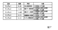
図7は、各乱数を示す説明図である。各乱数は、以下のように使用される。(1)ラン
ダム1(MR1):大当りの種類(後述する通常大当り、確変大当り、突然確変大当り)
を決定する(大当り種別判定用)(2)ランダム2(MR2):変動パターンの種類(種
別)を決定する(変動パターン種別判定用)(3)ランダム3(MR3):変動パターン
(変動時間)を決定する(変動パターン判定用)(4)ランダム4(MR4):普通図柄
にもとづく当りを発生させるか否か決定する(普通図柄当り判定用)(5)ランダム5(
MR5):ランダム4の初期値を決定する(ランダム4初期値決定用)
FIG. 7 is an explanatory diagram showing each random number. Each random number is used as follows. (1) Random 1 (MR1): Type of jackpot (normal jackpot, probability variation jackpot, sudden probability variation jackpot, which will be described later)
(For jackpot type judgment) (2) Random 2 (MR2): Determine the type (type) of the fluctuation pattern (for judgment of the fluctuation pattern type) (3) Random 3 (MR3): Fluctuation pattern (variation time) (For judgment of fluctuation pattern) (4) Random 4 (MR4): Determine whether or not to generate a hit based on a normal symbol (for judgment of hit of a normal symbol) (5) Random 5 (for judgment)
MR5): Determine the initial value of random 4 (for determining the initial value of random 4)
図5に示された遊技制御処理におけるステップS23では、遊技制御用マイクロコンピ
ュータ560は、(1)の大当り種別判定用乱数、および(4)の普通図柄当り判定用乱
数を生成するためのカウンタのカウントアップ(1加算)を行う。すなわち、それらが判
定用乱数であり、それら以外の乱数が表示用乱数(ランダム2、ランダム3)または初期
値用乱数(ランダム5)である。なお、遊技効果を高めるために、上記の乱数以外の乱数
も用いてもよい。また、この実施の形態では、大当り判定用乱数として、遊技制御用マイ
クロコンピュータ560に内蔵されたハードウェア(遊技制御用マイクロコンピュータ5
60の外部のハードウェアでもよい。)が生成する乱数を用いる。なお、大当り判定用乱
数として、ハードウェア乱数ではなく、ソフトウェア乱数を用いてもよい。
In step S23 in the game control process shown in FIG. 5, the
It may be 60 external hardware. ) Generates a random number. As the big hit determination random number, a software random number may be used instead of the hardware random number.
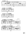
図8(A)は、大当り判定テーブルを示す説明図である。大当り判定テーブルとは、R
OM54に記憶されているデータの集まりであって、ランダムRと比較される大当り判定
値が設定されているテーブルである。大当り判定テーブルには、通常状態や時短状態(す
なわち、確変状態でない遊技状態)において用いられる通常時大当り判定テーブルと、確
変状態において用いられる確変時大当り判定テーブルとがある。通常時大当り判定テーブ
ルには、図8(A)の左欄に記載されている各数値が設定され、確変時大当り判定テーブ
ルには、図8(A)の右欄に記載されている各数値が設定されている。図8(A)に記載
されている数値が大当り判定値である。
FIG. 8A is an explanatory diagram showing a jackpot determination table. The jackpot judgment table is R
It is a collection of data stored in the
図8(B),(C)は、小当り判定テーブルを示す説明図である。小当り判定テーブル
とは、ROM54に記憶されているデータの集まりであって、ランダムRと比較される小
当り判定値が設定されているテーブルである。小当り判定テーブルには、第1特別図柄の
変動表示を行うときに用いられる小当り判定テーブル(第1特別図柄用)と、第2特別図
柄の変動表示を行うときに用いられる小当り判定テーブル(第2特別図柄用)とがある。
小当り判定テーブル(第1特別図柄用)には、図8(B)に記載されている各数値が設定
され、小当り判定テーブル(第2特別図柄用)には、図8(C)に記載されている各数値
が設定されている。また、図8(B),(C)に記載されている数値が小当り判定値であ
る。
8 (B) and 8 (C) are explanatory views showing a small hit determination table. The small hit determination table is a collection of data stored in the
Each numerical value shown in FIG. 8 (B) is set in the small hit determination table (for the first special symbol), and in FIG. 8 (C) in the small hit determination table (for the second special symbol). Each of the listed values is set. Further, the numerical values shown in FIGS. 8 (B) and 8 (C) are small hit determination values.
CPU56は、所定の時期に、乱数回路503のカウント値を抽出して抽出値を大当り
判定用乱数(ランダムR)の値とするのであるが、大当り判定用乱数値が図8(A)に示
すいずれかの大当り判定値に一致すると、特別図柄に関して大当り(後述する通常大当り
、確変大当り、突然確変大当り)にすることに決定する。また、大当り判定用乱数値が図
8(B),(C)に示すいずれかの小当り判定値に一致すると、特別図柄に関して小当り
にすることに決定する。なお、図8(A)に示す「確率」は、大当りになる確率(割合)
を示す。また、図8(B),(C)に示す「確率」は、小当りになる確率(割合)を示す
。また、大当りにするか否か決定するということは、大当り遊技状態に移行させるか否か
決定するということであるが、第1特別図柄表示器8aまたは第2特別図柄表示器8bに
おける停止図柄を大当り図柄にするか否か決定するということでもある。また、小当りに
するか否か決定するということは、小当り遊技状態に移行させるか否か決定するというこ
とであるが、第1特別図柄表示器8aまたは第2特別図柄表示器8bにおける停止図柄を
小当り図柄にするか否か決定するということでもある。
The
Is shown. Further, the "probability" shown in FIGS. 8 (B) and 8 (C) indicates the probability (ratio) of a small hit. Further, deciding whether or not to make a big hit means deciding whether or not to shift to the big hit game state, but the stop symbol in the first
なお、この実施の形態では、図8(B),(C)に示すように、小当り判定テーブル(
第1特別図柄用)を用いる場合には300分の1の割合で小当りと決定されるのに対して
、小当り判定テーブル(第2特別図柄)を用いる場合には3000分の1の割合で小当り
と決定される場合を説明する。従って、この実施の形態では、第1始動入賞口13に始動
入賞して第1特別図柄の変動表示が実行される場合には、第2始動入賞口14に始動入賞
して第2特別図柄の変動表示が実行される場合と比較して、「小当り」と決定される割合
が高い。
In this embodiment, as shown in FIGS. 8B and 8C, the small hit determination table (
When using the first special symbol), the small hit is determined at a rate of 1/300, while when using the small hit determination table (for the second special symbol), the rate is 1/3000. The case where it is determined to be a small hit will be described. Therefore, in this embodiment, when the first
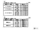
図8(D),(E)は、ROM54に記憶されている大当り種別判定テーブル131a
,131bを示す説明図である。このうち、図8(D)は、遊技球が第1始動入賞口13
に入賞したことにもとづく保留記憶を用いて(すなわち、第1特別図柄の変動表示が行わ
れるとき)大当り種別を決定する場合の大当り種別判定テーブル(第1特別図柄用)13
1aである。また、図8(E)は、遊技球が第2始動入賞口14に入賞したことにもとづ
く保留記憶を用いて(すなわち、第2特別図柄の変動表示が行われるとき)大当り種別を
決定する場合の大当り種別判定テーブル(第2特別図柄用)131bである。
8 (D) and 8 (E) show the jackpot type determination table 131a stored in the
, 131b. Of these, in FIG. 8D, the game ball is the first
The jackpot type determination table (for the first special symbol) when determining the jackpot type using the hold memory based on winning the prize (that is, when the variable display of the first special symbol is performed) 13
1a. Further, FIG. 8 (E) shows a case where the jackpot type is determined by using the hold memory based on the game ball winning the second start winning opening 14 (that is, when the variation display of the second special symbol is performed). It is a jackpot type determination table (for the second special symbol) 131b.
大当り種別判定テーブル131a,131bは、可変表示結果を大当り図柄にする旨の
判定がなされたときに、大当り種別判定用の乱数(ランダム1)にもとづいて、大当りの
種別を「通常大当り」、「確変大当り」、「突然確変大当り」のうちのいずれかに決定す
るために参照されるテーブルである。なお、この実施の形態では、図8(D),(E)に
示すように、大当り種別判定テーブル131aには「突然確変大当り」に対して5個の判
定値が割り当てられている(40分の5の割合で突然確変大当りと決定される)のに対し
て、大当り種別判定テーブル131bには「突然確変大当り」に対して1個の判定値が割
り当てられている(40分の1の割合で突然確変大当りと決定される)場合を説明する。
従って、この実施の形態では、第1始動入賞口13に始動入賞して第1特別図柄の変動表
示が実行される場合には、第2始動入賞口14に始動入賞して第2特別図柄の変動表示が
実行される場合と比較して、「突然確変大当り」と決定される割合が高い。なお、第1特
別図柄用の大当り種別判定テーブル131aにのみ「突然確変大当り」を振り分けるよう
にし、第2特別図柄用の大当り種別判定テーブル131bには「突然確変大当り」の振り
分けを行わない(すなわち、第1特別図柄の変動表示を行う場合にのみ、「突然確変大当
り」と決定される場合がある)ようにしてもよい。
The jackpot type determination tables 131a and 131b set the jackpot type to "normal jackpot" or "normal jackpot" based on a random number (random 1) for determining the jackpot type when it is determined that the variable display result is a jackpot symbol. It is a table referred to for determining either "probability change jackpot" or "sudden change jackpot". In this embodiment, as shown in FIGS. 8D and 8E, the jackpot type determination table 131a is assigned five determination values for the “sudden probability variation jackpot” (40 minutes). In contrast to the jackpot type judgment table 131b, one judgment value is assigned to the "sudden probability change jackpot" (1/40 percentage). (Suddenly determined to be a probabilistic jackpot).
Therefore, in this embodiment, when the first
この実施の形態では、図8(D),(E)に示すように、大当り種別として、「通常大
当り」、「確変大当り」および「突然確変大当り」がある。なお、この実施の形態では、
大当り遊技において実行されるラウンド数が15ラウンドおよび2ラウンドの2種類であ
る場合を示しているが、大当り遊技において実行されるラウンド数は、この実施の形態で
示したものに限られない。例えば、10ラウンドの大当り遊技に制御する10R確変大当
りや、7ラウンドの大当り遊技に制御する7R確変大当り、5ラウンドの大当り遊技に制
御する5R確変大当りが設けられていてもよい。また、この実施の形態では、大当り種別
が「通常大当り」、「確変大当り」および「突然確変大当り」の3種類である場合を示し
ているが、3種類にかぎらず、例えば、4種類以上の大当り種別を設けるようにしてもよ
い。また、逆に、大当り種別が3種類よりも少なくてもよく、例えば、大当り種別として
2種類のみ設けられていてもよい。
In this embodiment, as shown in FIGS. 8 (D) and 8 (E), the jackpot types include "normal jackpot", "probability jackpot", and "sudden probability variable jackpot". In addition, in this embodiment,
Although the case where the number of rounds executed in the jackpot game is two types of 15 rounds and 2 rounds is shown, the number of rounds executed in the jackpot game is not limited to that shown in this embodiment. For example, a 10R probability variable jackpot controlled for a 10-round jackpot game, a 7R probability variable jackpot controlled for a 7-round jackpot game, and a 5R probability variable jackpot controlled for a 5-round jackpot game may be provided. Further, in this embodiment, the case where the big hit types are three types of "normal big hit", "probability change big hit" and "sudden change big hit" is shown, but the case is not limited to three types, for example, four or more types. A jackpot type may be provided. On the contrary, the number of jackpot types may be less than three, and for example, only two types may be provided as jackpot types.
「通常大当り」とは、15ラウンドの大当り遊技状態に制御し、その大当り遊技状態の
終了後に時短状態のみに移行させる大当りである(後述するステップS167参照)。そ
して、時短状態に移行した後、変動表示を所定回数(この実施の形態では100回)終了
すると時短状態が終了する(ステップS168,S137〜S140参照)。なお、変動
表示を所定回数終了する前であっても、次の大当りが発生した場合にも、時短状態を終了
する(ステップS132参照)。
The "normal jackpot" is a jackpot that is controlled to a jackpot gaming state of 15 rounds and shifts to only a time saving state after the end of the jackpot gaming state (see step S167 described later). Then, after shifting to the time saving state, when the variation display is completed a predetermined number of times (100 times in this embodiment), the time saving state ends (see steps S168 and S137 to S140). Even before the end of the fluctuation display a predetermined number of times, the time saving state is ended even when the next big hit occurs (see step S132).
「確変大当り」とは、15ラウンドの大当り遊技状態に制御し、その大当り遊技状態の
終了後に確変状態に移行させる大当りである(この実施の形態では、確変状態に移行され
るとともに時短状態にも移行される。後述するステップS169,S170参照)。そし
て、次の大当りが発生するまで、確変状態および時短状態が継続する(ステップS132
参照)。
The "probability change jackpot" is a jackpot that controls the jackpot game state of 15 rounds and shifts to the probability change state after the end of the jackpot game state (in this embodiment, it shifts to the probability change state and also in the time saving state. Migrate. See steps S169 and S170 described later). Then, the probabilistic state and the time saving state continue until the next big hit occurs (step S132).
reference).
また、「突然確変大当り」とは、「通常大当り」や「確変大当り」と比較して大入賞口
の開放回数が少ない回数(この実施の形態では0.1秒間の開放を2回)まで許容される
大当りである。すなわち、「突然確変大当り」となった場合には、2ラウンドの大当り遊
技状態に制御される。また、「通常大当り」や「確変大当り」では、1ラウンドあたりの
大入賞口の開放時間が29秒と長いのに対して、「突然確変大当り」では1ラウンドあた
りの大入賞口の開放時間が0.1秒と極めて短く、大当り遊技中に大入賞口に遊技球が入
賞することは殆ど期待できない。そして、この実施の形態では、その突然確変大当り遊技
状態の終了後に確変状態に移行される(この実施の形態では、確変状態に移行されるとと
もに時短状態にも移行される。後述するステップS169,S170参照)。そして、次
の大当りが発生するまで、確変状態および時短状態が継続する(ステップS132参照)
。
Further, the "sudden change jackpot" is allowed up to the number of times that the big winning opening is opened less than the "normal jackpot" and the "probability change jackpot" (in this embodiment, the opening for 0.1 second is twice). It is a big hit to be done. That is, in the case of "sudden probability change big hit", it is controlled to the big hit game state of two rounds. In addition, in "normal jackpot" and "probability jackpot", the opening time of the jackpot per round is as long as 29 seconds, while in "sudden jackpot", the opening time of the jackpot per round is long. It is extremely short at 0.1 seconds, and it can hardly be expected that a game ball will win a prize at the big prize opening during a big hit game. Then, in this embodiment, after the sudden end of the probabilistic jackpot gaming state, the probabilistic state is shifted (in this embodiment, the probabilistic state is shifted and the time is shortened as well. Step S169, which will be described later, See S170). Then, the probabilistic state and the time saving state continue until the next big hit occurs (see step S132).
..
なお、突然確変大当りの態様は、この実施の形態で示したものにかぎられない。例えば
、大入賞口の開放回数は通常大当りや突然確変大当りと同じ15回(15ラウンド)とし
、大入賞口の開放時間のみ0.1秒と極めて短くするようにしてもよい。
The mode of the sudden change jackpot is not limited to that shown in this embodiment. For example, the number of times the big winning opening is opened may be 15 times (15 rounds), which is the same as a normal big hit or a sudden change big hit, and only the opening time of the big winning opening may be extremely short, 0.1 seconds.
なお、この実施の形態では、「小当り」となった場合にも、大入賞口の開放が0.1秒
間ずつ2回行われ、「突然確変大当り」による大当り遊技状態と同様の制御が行われる。
そして、「小当り」となった場合には、大入賞口の2回の開放が終了した後、遊技状態は
変化せず、「小当り」となる前の遊技状態が維持される。そのようにすることによって、
「突然確変大当り」であるか「小当り」であるかを認識できないようにし、遊技の興趣を
向上させている。なお、大当り種別が全て確変大当りであるように構成する場合、小当り
を設けなくてもよい。また、大当り種別が全て確変大当りである場合に小当りを設けるよ
うに構成する場合には、確変状態(高確率状態)に移行されるのみで時短状態(高ベース
状態)を伴わない突然確変大当りを設けるようにすること(大入賞口の開放パターンも突
然確変大当りと小当りの場合とで同じにすること)が好ましい。
In this embodiment, even when a "small hit" occurs, the big winning opening is opened twice for 0.1 seconds each, and the same control as in the big hit game state by the "sudden probability change big hit" is performed. Will be.
Then, in the case of a "small hit", the gaming state does not change after the two opening of the large winning opening is completed, and the gaming state before the "small hit" is maintained. By doing so
It makes it impossible to recognize whether it is a "sudden change big hit" or a "small hit", and improves the interest of the game. If all the big hit types are configured to be probabilistic big hits, it is not necessary to provide small hits. In addition, when a small hit is provided when all the jackpot types are probability variable jackpots, the sudden probability variable jackpot is only shifted to the probability variation state (high probability state) and is not accompanied by the time saving state (high base state). It is preferable to provide the above (the opening pattern of the big winning opening is also the same for the sudden change big hit and the small hit).
大当り種別判定テーブル131a,131bには、ランダム1の値と比較される数値で
あって、「通常大当り」、「確変大当り」、「突然確変大当り」のそれぞれに対応した判
定値(大当り種別判定値)が設定されている。CPU56は、ランダム1の値が大当り種
別判定値のいずれかに一致した場合に、大当りの種別を、一致した大当り種別判定値に対
応する種別に決定する。
The jackpot type judgment tables 131a and 131b are numerical values to be compared with the value of random 1, and are judgment values corresponding to each of "normal jackpot", "probability variation jackpot", and "sudden probability variation jackpot" (big hit type judgment value). ) Is set. When the value of random 1 matches any of the jackpot type determination values, the
図9(A)〜(C)は、大当り用変動パターン種別判定テーブル132A〜132Cを
示す説明図である。大当り用変動パターン種別判定テーブル132A〜132Cは、可変
表示結果を大当り図柄にする旨の判定がなされたときに、大当り種別の判定結果に応じて
、変動パターン種別を、変動パターン種別判定用の乱数(ランダム2)にもとづいて複数
種類のうちのいずれかに決定するために参照されるテーブルである。
9 (A) to 9 (C) are explanatory views showing fluctuation pattern type determination tables 132A to 132C for big hits. In the jackpot variation pattern type determination tables 132A to 132C, when it is determined that the variable display result is a jackpot symbol, the variation pattern type is set to a random number for the variation pattern type determination according to the determination result of the jackpot type. It is a table referred to for determining one of a plurality of types based on (random number 2).
各大当り用変動パターン種別判定テーブル132A〜132Cには、変動パターン種別
判定用の乱数(ランダム2)の値と比較される数値(判定値)であって、ノーマルCA3
−1〜ノーマルCA3−2、スーパーCA3−3、特殊CA4−1、特殊CA4−2の変
動パターン種別のいずれかに対応する判定値が設定されている。
The fluctuation pattern type determination tables 132A to 132C for each jackpot are numerical values (judgment values) to be compared with the values of the random numbers (random 2) for the fluctuation pattern type determination, and are normal CA3.
Judgment values corresponding to any of the fluctuation pattern types of -1 to normal CA3-2, super CA3-3, special CA4-1, and special CA4-2 are set.
例えば、大当り種別が「通常大当り」である場合に用いられる図9(A)に示す大当り
用変動パターン種別判定テーブル132Aと、大当り種別が「確変大当り」である場合に
用いられる図9(B)に示す大当り用変動パターン種別判定テーブル132Bとで、ノー
マルCA3−1〜ノーマルCA3−2、スーパーCA3−3の変動パターン種別に対する
判定値の割り当てが異なっている。
For example, the variation pattern type determination table 132A for jackpot shown in FIG. 9 (A) used when the jackpot type is "normal jackpot" and FIG. 9 (B) used when the jackpot type is "probability variation jackpot". The allocation of judgment values for the fluctuation pattern types of normal CA3-1 to normal CA3-2 and super CA3-3 is different from that of the jackpot fluctuation pattern type determination table 132B shown in.
このように、大当り種別に応じて選択される大当り用変動パターン種別判定テーブル1
32A〜132Cを比較すると、大当り種別に応じて各変動パターン種別に対する判定値
の割り当てが異なっている。また、大当り種別に応じて異なる変動パターン種別に対して
判定値が割り当てられている。よって、大当り種別を複数種類のうちのいずれにするかの
決定結果に応じて、異なる変動パターン種別に決定することができ、同一の変動パターン
種別に決定される割合を異ならせることができる。
In this way, the jackpot variation pattern type determination table 1 selected according to the jackpot type.
Comparing 32A to 132C, the assignment of the determination value for each variation pattern type is different depending on the jackpot type. In addition, judgment values are assigned to different fluctuation pattern types according to the jackpot type. Therefore, different variation pattern types can be determined according to the determination result of which of the plurality of types the jackpot type is to be used, and the ratios determined for the same variation pattern type can be different.
なお、図9(A),(B)に示すように、この実施の形態では、「通常大当り」または
「確変大当り」である場合には、変動パターン種別判定用の乱数(ランダム2)の値が1
50〜251であれば、少なくともスーパーリーチ(スーパーリーチA、スーパーリーチ
B)を伴う変動表示が実行されることがわかる。
As shown in FIGS. 9A and 9B, in this embodiment, in the case of "normal jackpot" or "probability variation jackpot", the value of a random number (random 2) for determining the variation pattern type. Is 1
If it is 50 to 251 it can be seen that the variable display with at least super reach (super reach A, super reach B) is executed.
また、スーパーリーチ大当りについて、擬似連を伴う変動パターン種別(スーパーPA
3−3、スーパーPA3−4の変動パターンを含む変動パターン種別)と、擬似連を伴わ
ない変動パターン種別(スーパーPB3−3、スーパーPB3−4の変動パターンを含む
変動パターン種別)とに分けてもよい。この場合、通常大当り用の大当り用変動パターン
種別判定テーブル132Aおよび確変大当り用の大当り用変動パターン種別判定テーブル
132Bの両方において、スーパーリーチかつ擬似連を伴う変動パターン種別と、スーパ
ーリーチかつ擬似連を伴わない変動パターン種別とが割り当てられることになる。
Also, regarding the super reach jackpot, the fluctuation pattern type with pseudo-ream (super PA)
It is divided into 3-3, fluctuation pattern types including fluctuation patterns of Super PA3-4) and fluctuation pattern types without pseudo-ream (variation pattern types including fluctuation patterns of Super PB3-3 and Super PB3-4). May be good. In this case, in both the jackpot variation pattern type determination table 132A for normal jackpot and the jackpot variation pattern type determination table 132B for probability variation jackpot, the variation pattern type with super reach and pseudo-ream and the super-reach and pseudo-ream are displayed. The fluctuation pattern type that does not accompany it will be assigned.
また、大当り種別が「突然確変大当り」である場合に用いられる大当り用変動パターン
種別判定テーブル132Cでは、例えば、特殊CA4−1、特殊CA4−2といった大当
り種別が「突然確変大当り」以外である場合には判定値が割り当てられない変動パターン
種別に対して、判定値が割り当てられている。よって、可変表示結果が「大当り」となり
大当り種別が「突然確変大当り」となることに応じて突然確変大当り状態に制御する場合
には、通常大当りや確変大当りによる大当り状態に制御する場合とは異なる変動パターン
種別に決定することができる。
Further, in the jackpot variation pattern type determination table 132C used when the jackpot type is "sudden probability variation jackpot", for example, when the jackpot type such as special CA4-1 and special CA4-2 is other than "sudden probability variation jackpot". A judgment value is assigned to a fluctuation pattern type to which a judgment value is not assigned. Therefore, when the variable display result becomes "big hit" and the big hit type becomes "sudden probability change big hit" and the sudden probability change big hit state is controlled, it is different from the case of controlling to the normal big hit or the big hit state by the probability change big hit. It can be determined according to the fluctuation pattern type.
また、図9(D)は、小当り用変動パターン種別判定テーブル132Dを示す説明図で
ある。小当り用変動パターン種別判定テーブル132Dは、可変表示結果を小当り図柄に
する旨の判定がなされたときに、変動パターン種別を、変動パターン種別判定用の乱数(
ランダム2)にもとづいて複数種類のうちのいずれかに決定するために参照されるテーブ
ルである。なお、この実施の形態では、図9(D)に示すように、小当りとすることに決
定されている場合には、変動パターン種別として特殊CA4−1が決定される場合が示さ
れている。
Further, FIG. 9D is an explanatory diagram showing the variation pattern type determination table 132D for small hits. The variation pattern type determination table 132D for small hits sets the variation pattern type to a random number for determining the variation pattern type (when it is determined that the variable display result is a small hit symbol.
It is a table referred to for determining one of a plurality of types based on random 2). In this embodiment, as shown in FIG. 9D, when it is decided to make a small hit, a case where special CA4-1 is determined as a fluctuation pattern type is shown. ..
図10(A)〜(C)は、はずれ用変動パターン種別判定テーブル135A〜135C
を示す説明図である。このうち、図10(A)は、遊技状態が通常状態であるとともに合
算保留記憶数が3未満である場合に用いられるはずれ用変動パターン種別判定テーブル1
35Aを示している。また、図10(B)は、遊技状態が通常状態であるとともに合算保
留記憶数が3以上である場合に用いられるはずれ用変動パターン種別判定テーブル135
Bを示している。また、図10(C)は、遊技状態が確変状態や時短状態である場合に用
いられるはずれ用変動パターン種別判定テーブル135Cを示している。はずれ用変動パ
ターン種別判定テーブル135A〜135Cは、可変表示結果をはずれ図柄にする旨の判
定がなされたときに、変動パターン種別を、変動パターン種別判定用の乱数(ランダム2
)にもとづいて複数種類のうちのいずれかに決定するために参照されるテーブルである。
10 (A) to 10 (C) show the deviation pattern type determination tables 135A to 135C.
It is explanatory drawing which shows. Of these, FIG. 10 (A) shows the deviation pattern type determination table 1 used when the gaming state is the normal state and the total number of pending storages is less than 3.
It shows 35A. Further, FIG. 10B shows a variation pattern type determination table 135 for deviation, which is used when the game state is the normal state and the total number of reserved storages is 3 or more.
B is shown. Further, FIG. 10C shows a variation pattern type determination table 135C for deviation, which is used when the gaming state is a probability change state or a time saving state. The deviation pattern type determination tables 135A to 135C set the variation pattern type to a random number (random 2) for determining the variation pattern type when it is determined that the variable display result is an outlier.
) Is a table referenced to determine one of a plurality of types.
各はずれ用変動パターン種別判定テーブル135A〜135Bには、変動パターン種別
判定用の乱数(ランダム2)の値と比較される数値(判定値)であって、非リーチCA2
−1〜非リーチCA2−2、ノーマルCA2−3〜ノーマルCA2−4、スーパーCA2
−5の変動パターン種別のいずれかに対応する判定値が設定されている。
In each of the deviation pattern type determination tables 135A to 135B, numerical values (judgment values) to be compared with the values of random numbers (random 2) for determination of the variation pattern type are shown in the non-reach CA2.
-1 to non-reach CA2-2, normal CA2-3 to normal CA2-4, super CA2
A judgment value corresponding to any of the fluctuation pattern types of -5 is set.
なお、図10(A),(B)に示すように、この実施の形態では、はずれであるととも
に遊技状態が通常状態である場合には、変動パターン種別判定用の乱数(ランダム2)の
値が230〜251であれば、合算保留記憶数にかかわらず、少なくともスーパーリーチ
(スーパーリーチA、スーパーリーチB)を伴う変動表示が実行されることがわかる。
As shown in FIGS. 10A and 10B, in this embodiment, when the game is out of alignment and the game state is the normal state, the value of the random number (random 2) for determining the variation pattern type When is 230 to 251 it can be seen that the variable display with at least super reach (super reach A, super reach B) is executed regardless of the total number of reserved storages.
また、図10(A)、(B)に示すように、この実施の形態では、はずれであるととも
に遊技状態が通常状態である場合には、変動パターン種別判定用の乱数(ランダム2)の
値が1〜89であれば、合算保留記憶数にかかわらず、少なくともリーチを伴わない(擬
似連や滑り演出などの演出も伴わない)通常変動の変動表示が実行されること(非リーチ
CA2−1の変動パターン種別となることから、後述する図12に示すように非リーチ通
常変動の非リーチPA1−1の変動パターンとなること)がわかる。そのようなテーブル
構成により、この実施の形態では、判定テーブル(はずれ用変動パターン種別判定テーブ
ル135A,135B)は、リーチ用可変表示パターン(リーチを伴う変動パターン)以
外の可変表示パターンのうちの少なくとも一部に対して、保留記憶手段(第1保留記憶バ
ッファや第2保留記憶バッファ)が記憶する権利の数(第1保留記憶数や第2保留記憶数
、合算保留記憶数)にかかわらず、共通の判定値(図10(A),(B)に示す例では1
〜89)が割り当てられるように構成されている。なお、「リーチ用可変表示パターン以
外の可変表示パターン」とは、この実施の形態で示したように、例えば、リーチを伴わず
、擬似連や滑り演出などの演出も伴わず、可変表示結果が大当りとならない場合に用いら
れる可変表示パターン(変動パターン)のことである。
Further, as shown in FIGS. 10A and 10B, in this embodiment, when the game is out of alignment and the game state is the normal state, the value of the random number (random 2) for determining the variation pattern type If is 1 to 89, the fluctuation display of normal fluctuation is executed at least without reach (without effects such as pseudo-ream or slip effect) regardless of the total number of reserved memories (non-reach CA2-1). As shown in FIG. 12, which will be described later, it is a non-reach normal variation non-reach PA1-1 variation pattern). Due to such a table configuration, in this embodiment, the determination table (variable pattern type determination table 135A, 135B for loss) is at least one of the variable display patterns other than the variable display pattern for reach (variable pattern with reach). Regardless of the number of rights to be stored by the hold storage means (first hold storage buffer or second hold storage buffer) (first hold storage number, second hold storage number, total hold storage number). Common judgment value (1 in the example shown in FIGS. 10A and 10B)
~ 89) is configured to be assigned. As shown in this embodiment, the "variable display pattern other than the variable display pattern for reach" means that, for example, the variable display result is not accompanied by a reach, and is not accompanied by an effect such as a pseudo-ream or a sliding effect. It is a variable display pattern (variable pattern) used when it does not become a big hit.
図11(A),(B)は、ROM54に記憶されている当り変動パターン判定テーブル
137A〜137Bを示す説明図である。当り変動パターン判定テーブル137A〜13
7Bは、可変表示結果を「大当り」や「小当り」にする旨の判定がなされたときに、大当
り種別や変動パターン種別の決定結果などに応じて、変動パターン判定用の乱数(ランダ
ム3)にもとづいて、変動パターンを複数種類のうちのいずれかに決定するために参照さ
れるテーブルである。各当り変動パターン判定テーブル137A〜137Bは、変動パタ
ーン種別の決定結果に応じて、使用テーブルとして選択される。すなわち、変動パターン
種別をノーマルCA3−1〜ノーマルCA3−2、スーパーCA3−3のいずれかにする
旨の決定結果に応じて当り変動パターン判定テーブル137Aが使用テーブルとして選択
され、変動パターン種別を特殊CA4−1、特殊CA4−2のいずれかにする旨の決定結
果に応じて当り変動パターン判定テーブル137Bが使用テーブルとして選択される。各
当り変動パターン判定テーブル137A〜137Bは、変動パターン種別に応じて、変動
パターン判定用の乱数(ランダム3)の値と比較される数値(判定値)であって、演出図
柄の可変表示結果が「大当り」である場合に対応した複数種類の変動パターンのいずれか
に対応するデータ(判定値)を含む。
11 (A) and 11 (B) are explanatory views showing the hit variation pattern determination tables 137A to 137B stored in the
In 7B, when it is determined that the variable display result is "big hit" or "small hit", a random number (random 3) for determining the fluctuation pattern is determined according to the determination result of the big hit type or the fluctuation pattern type. Based on this, it is a table referenced to determine the variation pattern to one of a plurality of types. The fluctuation pattern determination tables 137A to 137B for each are selected as the tables to be used according to the determination result of the fluctuation pattern type. That is, the hit variation pattern determination table 137A is selected as the table to be used according to the determination result that the variation pattern type is set to either normal CA3-1 to normal CA3-2 or super CA3-3, and the variation pattern type is special. The hit variation pattern determination table 137B is selected as the table to be used according to the determination result of either CA4-1 or special CA4-2. Each of the fluctuation pattern determination tables 137A to 137B is a numerical value (judgment value) to be compared with the value of the random number (random 3) for the fluctuation pattern determination according to the variation pattern type, and the variable display result of the effect symbol is Includes data (judgment value) corresponding to any of a plurality of types of fluctuation patterns corresponding to the case of "big hit".
図12は、ROM54に記憶されているはずれ変動パターン判定テーブル138Aを示
す説明図である。はずれ変動パターン判定テーブル138Aは、可変表示結果を「はずれ
」にする旨の判定がなされたときに、変動パターン種別の決定結果に応じて、変動パター
ン判定用の乱数(ランダム3)にもとづいて、変動パターンを複数種類のうちのいずれか
に決定するために参照されるテーブルである。はずれ変動パターン判定テーブル138A
は、変動パターン種別の決定結果に応じて、使用テーブルとして選択される。
FIG. 12 is an explanatory diagram showing the deviation variation pattern determination table 138A stored in the
Is selected as the table to be used according to the determination result of the fluctuation pattern type.
図13および図14は、遊技制御用マイクロコンピュータ560が送信する演出制御コ
マンドの内容の一例を示す説明図である。図13および図14に示す例において、コマン
ド80XX(H)は、特別図柄の可変表示に対応して演出表示装置9において可変表示さ
れる演出図柄の変動パターンを指定する演出制御コマンド(変動パターンコマンド)であ
る(それぞれ変動パターンXXに対応)。つまり、図6に示された使用されうる変動パタ
ーンのそれぞれに対して一意な番号を付した場合に、その番号で特定される変動パターン
のそれぞれに対応する変動パターンコマンドがある。なお、「(H)」は16進数である
ことを示す。また、変動パターンを指定する演出制御コマンドは、変動開始を指定するた
めのコマンドでもある。従って、演出制御用マイクロコンピュータ100は、コマンド8
0XX(H)を受信すると、演出表示装置9において演出図柄の可変表示を開始するよう
に制御する。
13 and 14 are explanatory views showing an example of the contents of the effect control command transmitted by the
When 0XX (H) is received, the
コマンド8C01(H)〜8C05(H)は、大当りとするか否か、小当りとするか否
か、および大当り種別を示す演出制御コマンドである。演出制御用マイクロコンピュータ
100は、コマンド8C01(H)〜8C05(H)の受信に応じて演出図柄の表示結果
を決定するので、コマンド8C01(H)〜8C05(H)を表示結果指定コマンドとい
う。
The commands 8C01 (H) to 8C05 (H) are effect control commands indicating whether or not to make a big hit, whether or not to make a small hit, and the type of big hit. Since the
コマンド8D01(H)は、第1特別図柄の可変表示(変動)を開始することを示す演
出制御コマンド(第1図柄変動指定コマンド)である。コマンド8D02(H)は、第2
特別図柄の可変表示(変動)を開始することを示す演出制御コマンド(第2図柄変動指定
コマンド)である。第1図柄変動指定コマンドと第2図柄変動指定コマンドとを特別図柄
特定コマンド(または図柄変動指定コマンド)と総称することがある。なお、第1特別図
柄の可変表示を開始するのか第2特別図柄の可変表示を開始するのかを示す情報を、変動
パターンコマンドに含めるようにしてもよい。
The command 8D01 (H) is an effect control command (first symbol variation designation command) indicating that the variable display (variation) of the first special symbol is started. Command 8D02 (H) is the second
This is an effect control command (second symbol variation designation command) indicating that the variable display (variation) of the special symbol is started. The first symbol variation designation command and the second symbol variation designation command may be collectively referred to as a special symbol specification command (or symbol variation designation command). The variation pattern command may include information indicating whether to start the variable display of the first special symbol or the variable display of the second special symbol.
コマンド8F00(H)は、第4図柄の可変表示(変動)を終了して表示結果(停止図
柄)を導出表示することを示す演出制御コマンド(図柄確定指定コマンド)である。演出
制御用マイクロコンピュータ100は、図柄確定指定コマンドを受信すると、第4図柄の
可変表示(変動)を終了して表示結果を導出表示する。
The command 8F00 (H) is an effect control command (symbol confirmation designation command) indicating that the variable display (variation) of the fourth symbol is terminated and the display result (stop symbol) is derived and displayed. Upon receiving the symbol confirmation designation command, the
コマンド9000(H)は、遊技機に対する電力供給が開始されたときに送信される演
出制御コマンド(初期化指定コマンド:電源投入指定コマンド)である。コマンド920
0(H)は、遊技機に対する電力供給が再開されたときに送信される演出制御コマンド(
停電復旧指定コマンド)である。遊技制御用マイクロコンピュータ560は、遊技機に対
する電力供給が開始されたときに、バックアップRAMにデータが保存されている場合に
は、停電復旧指定コマンドを送信し、そうでない場合には、初期化指定コマンドを送信す
る。
The command 9000 (H) is an effect control command (initialization designation command: power-on designation command) transmitted when the power supply to the game machine is started. Command 920
0 (H) is an effect control command (H) that is transmitted when the power supply to the game machine is restarted.
Power failure recovery designation command). When the power supply to the game machine is started, the
コマンド9F00(H)は、客待ちデモンストレーションを指定する演出制御コマンド
(客待ちデモ指定コマンド)である。
The command 9F00 (H) is a production control command (customer waiting demo designation command) for designating a customer waiting demonstration.
コマンドA001,A002(H)は、ファンファーレ画面を表示すること、すなわち
大当り遊技の開始を指定する演出制御コマンド(大当り開始指定コマンド:ファンファー
レ指定コマンド)である。この実施の形態では、大当りの種類に応じて、大当り開始指定
コマンドまたは小当り/突然確変大当り開始指定コマンドが用いられる。具体的には、「
通常大当り」や「確変大当り」である場合には大当り開始指定コマンド(A001(H)
)が用いられ、「突然確変大当り」や「小当り」である場合には小当り/突然確変大当り
開始指定コマンド(A002(H))が用いられる。なお、遊技制御用マイクロコンピュ
ータ560は、突然大当りである場合に突然確変大当り開始指定用のファンファーレ指定
コマンドを送信するものの、小当りである場合にはファンファーレ指定コマンドを送信し
ないように構成してもよい。
The commands A001 and A002 (H) are effect control commands (big hit start designation command: fanfare designation command) for displaying the fanfare screen, that is, designating the start of the jackpot game. In this embodiment, a jackpot start designation command or a small hit / sudden probability change jackpot start designation command is used depending on the type of jackpot. In particular,"
In the case of "normal jackpot" or "probability variable jackpot", the jackpot start designation command (A001 (H))
) Is used, and in the case of "sudden probability change big hit" or "small hit", the small hit / sudden probability change big hit start designation command (A002 (H)) is used. Although the
コマンドA1XX(H)は、XXで示す回数目(ラウンド)の大入賞口開放中の表示を
示す演出制御コマンド(大入賞口開放中指定コマンド)である。また、A2XX(H)は
、XXで示す回数目(ラウンド)の大入賞口閉鎖を示す演出制御コマンド(大入賞口開放
後指定コマンド)である。
The command A1XX (H) is an effect control command (command for designating the opening of the winning opening) indicating the display during the opening of the winning opening for the number of times (round) indicated by XX. Further, A2XX (H) is an effect control command (designated command after opening the large winning opening) indicating the closing of the large winning opening for the number of times (round) indicated by XX.
コマンドA301(H)は、大当り終了画面を表示すること、すなわち大当り遊技の終
了を指定する演出制御コマンド(大当り終了指定コマンド:エンディング1指定コマンド
)である。なお、大当り終了指定コマンド(A301(H))は、「通常大当り」や「確
変大当り」による大当り遊技を終了する場合に用いられる。コマンドA302(H)は、
小当りの遊技の終了または突然確変大当りの遊技の終了を指定する演出制御コマンド(小
当り/突然確変大当り終了指定コマンド:エンディング2指定コマンド)である。なお、
遊技制御用マイクロコンピュータ560は、突然確変大当りである場合に突然確変大当り
終了指定用のエンディング指定コマンドを送信するものの、小当りである場合にはエンデ
ィング指定コマンドを送信しないように構成してもよい。
The command A301 (H) is an effect control command (big hit end designation command: ending 1 designation command) for displaying the jackpot end screen, that is, designating the end of the jackpot game. The jackpot end designation command (A301 (H)) is used when ending the jackpot game by "normal jackpot" or "probability variation jackpot". Command A302 (H) is
This is an effect control command (small hit / sudden probability change big hit end designation command: ending 2 designation command) that specifies the end of the small hit game or the end of the sudden probability change big hit game. In addition, it should be noted
The
コマンドB000(H)は、遊技状態が通常状態であるときの背景表示を指定する演出
制御コマンド(通常状態背景指定コマンド)である。コマンドB001(H)は、遊技状
態が確変状態であるときの背景表示を指定する演出制御コマンド(確変状態背景指定コマ
ンド)である。コマンドB002(H)は、遊技状態が時短状態であるときの背景表示を
指定する演出制御コマンド(時短状態背景指定コマンド)である。
The command B000 (H) is an effect control command (normal state background designation command) for designating the background display when the game state is the normal state. The command B001 (H) is an effect control command (probability change state background designation command) for designating the background display when the game state is the probability change state. The command B002 (H) is an effect control command (time saving state background designation command) for designating the background display when the gaming state is the time saving state.
コマンドC000(H)は、第1保留記憶数が1増加したことを指定する演出制御コマ
ンド(第1保留記憶数加算指定コマンド)である。コマンドC100(H)は、第2保留
記憶数が1増加したことを指定する演出制御コマンド(第2保留記憶数加算指定コマンド
)である。コマンドC200(H)は、第1保留記憶数が1減少したことを指定する演出
制御コマンド(第1保留記憶数減算指定コマンド)である。コマンドC300(H)は、
第2保留記憶数が1減少したことを指定する演出制御コマンド(第2保留記憶数減算指定
コマンド)である。
The command C000 (H) is an effect control command (first hold storage number addition designation command) that specifies that the first hold storage number has increased by 1. The command C100 (H) is an effect control command (second hold storage number addition designation command) for designating that the second hold storage number has been increased by 1. The command C200 (H) is an effect control command (first hold storage number subtraction designation command) for designating that the first hold storage number has decreased by 1. Command C300 (H) is
This is an effect control command (second hold storage number subtraction designation command) that specifies that the second hold storage number has decreased by 1.
なお、この実施の形態では、保留記憶情報として、第1保留記憶数と第2保留記憶数と
について、それぞれ保留記憶数が増加または減少したことを示す演出制御コマンド(第1
保留記憶数加算指定コマンド、第2保留記憶数加算指定コマンド、第1保留記憶数減算指
定コマンド、第2保留記憶数減算指定コマンド)を送信する場合を示しているが、保留記
憶情報の形態は、この実施の形態で示したものにかぎらず、例えば、以下のような態様の
保留記憶情報を送信するようにしてもよい。
In this embodiment, as the reserved storage information, the effect control command (first) indicating that the reserved storage number has increased or decreased for the first reserved storage number and the second reserved storage number, respectively.
The case of transmitting the hold storage number addition specification command, the second hold storage number addition specification command, the first hold storage number subtraction specification command, and the second hold storage number subtraction specification command) is shown, but the form of the hold storage information , Not limited to those shown in this embodiment, for example, the reserved storage information in the following aspects may be transmitted.
(1)保留記憶情報として、1つのコマンドのみを送信し、その1つのコマンドにおいて
、第1保留記憶と第2保留記憶とのいずれが増加したかを指定するとともに、増加した方
の保留記憶数(第1保留記憶数または第2保留記憶数)をEXTデータとして設定して送
信するようにしてもよい。
(1) As the hold storage information, only one command is transmitted, and in that one command, which of the first hold memory and the second hold memory is increased is specified, and the number of hold memories of the increased one is specified. (The first reserved storage number or the second reserved storage number) may be set as EXT data and transmitted.
(2)保留記憶情報として、1つのコマンドのみを送信し、その1つのコマンドにおいて
、第1保留記憶と第2保留記憶とのいずれが増加したかを指定するとともに、合算保留記
憶数をEXTデータとして設定して送信するようにしてもよい。
(2) As the hold storage information, only one command is transmitted, and in that one command, which of the first hold memory and the second hold memory is increased is specified, and the total number of hold memories is EXT data. It may be set as and sent.
(3)保留記憶情報として、第1始動入賞口13と第2始動入賞口14とのいずれに始動
入賞したか(第1保留記憶と第2保留記憶とのいずれが増加したか)を指定する演出制御
コマンド(第1始動入賞指定コマンド、第2始動入賞指定コマンド)を送信するとともに
、それとは別に保留記憶数を指定する保留記憶数指定コマンドを送信するようにし、その
保留記憶数指定コマンドにおいて合算保留記憶数をEXTデータとして設定して送信する
ようにしてもよい。
(3) As the reserved memory information, it is specified which of the first
(4)保留記憶情報として、第1始動入賞口13と第2始動入賞口14とのいずれに始動
入賞したか(第1保留記憶と第2保留記憶とのいずれが増加したか)を指定する演出制御
コマンド(第1始動入賞指定コマンド、第2始動入賞指定コマンド)を送信するとともに
、それとは別に保留記憶数を指定する保留記憶数指定コマンドを送信するようにし、その
保留記憶数指定コマンドにおいて増加した方の保留記憶数(第1保留記憶数または第2保
留記憶数)をEXTデータとして設定して送信するようにしてもよい。
(4) As the reserved memory information, it is specified which of the first
コマンドC4XX(H)およびコマンドC6XX(H)は、入賞時判定結果の内容を示
す演出制御コマンド(入賞時判定結果指定コマンド)である。このうち、コマンドC4X
X(H)は、入賞時判定結果のうち、大当りとなるか否かや、小当りとなるか否か、大当
りの種別の判定結果を示す演出制御コマンド(図柄指定コマンド)である。また、コマン
ドC6XX(H)は、入賞時判定結果のうち、変動パターン種別判定用乱数の値がいずれ
の判定値の範囲となるかの判定結果(変動パターン種別の判定結果)を示す演出制御コマ
ンド(変動カテゴリコマンド)である。
The command C4XX (H) and the command C6XX (H) are effect control commands (winning determination result designation commands) indicating the contents of the winning determination result. Of these, command C4X
X (H) is an effect control command (symbol designation command) indicating whether or not a big hit is obtained, whether or not a small hit is obtained, and a judgment result of the type of the big hit among the judgment results at the time of winning. Further, the command C6XX (H) is an effect control command indicating a judgment result (judgment result of the fluctuation pattern type) of which judgment value range the value of the random number for the fluctuation pattern type judgment falls within the judgment result at the time of winning. (Variable category command).
この実施の形態では、後述する入賞時演出処理(図22参照)において、遊技制御用マ
イクロコンピュータ560は、始動入賞時に、大当りとなるか否かや、小当りとなるか否
か、大当りの種別、変動パターン種別判定用乱数の値がいずれの判定値の範囲にとなるか
を判定する。そして、図柄指定コマンドのEXTデータに、大当りや小当りとなることを
指定する値や、大当りの種別を指定する値を設定し、演出制御用マイクロコンピュータ1
00に対して送信する制御を行う。また、変動カテゴリコマンドのEXTデータに判定結
果としての判定値の範囲を指定する値を設定し、演出制御用マイクロコンピュータ100
に対して送信する制御を行う。なお、この実施の形態では、演出制御用マイクロコンピュ
ータ100は、図柄指定コマンドに設定されている値にもとづいて、表示結果が大当りや
小当りとなるか否か、大当りの種別を認識できるとともに、変動カテゴリコマンドにもと
づいて、変動パターン種別判定用乱数の値が所定の判定値となる場合には変動パターン種
別を認識できる。
In this embodiment, in the winning effect processing (see FIG. 22) described later, the
Controls transmission for 00. In addition, a value that specifies a range of judgment values as a judgment result is set in the EXT data of the variable category command, and the
Controls transmission to. In this embodiment, the
図15は、図柄指定コマンドの内容の一例を示す説明図である。図15に示すように、
この実施の形態では、大当りや小当りとなるか否かと、大当りの種別とに応じて、EXT
データが設定され、図柄指定コマンドが送信される。
FIG. 15 is an explanatory diagram showing an example of the contents of the symbol designation command. As shown in FIG.
In this embodiment, EXT depends on whether or not it is a big hit or a small hit, and the type of the big hit.
The data is set and the symbol specification command is sent.
例えば、後述する入賞時演出処理において、「はずれ」となると判定された場合には、
CPU56は、EXTデータに「00(H)」を設定した図柄指定コマンド(図柄1指定
コマンド)を送信する。また、例えば、「通常大当り」となると判定された場合には、C
PU56は、EXTデータに「01(H)」を設定した図柄指定コマンド(図柄2指定コ
マンド)を送信する。また、例えば、「確変大当り」となると判定された場合には、CP
U56は、EXTデータに「02(H)」を設定した図柄指定コマンド(図柄3指定コマ
ンド)を送信する。また、例えば、「突然確変大当り」となると判定された場合には、C
PU56は、EXTデータに「03(H)」を設定した図柄指定コマンド(図柄4指定コ
マンド)を送信する。また、例えば、「小当り」となると判定された場合には、CPU5
6は、EXTデータに「04(H)」を設定した図柄指定コマンド(図柄5指定コマンド
)を送信する。なお、図柄指定コマンドに設定されるEXTデータと、表示結果指定コマ
ンドに設定されるEXTデータとを共通化してもよい。そのように構成すれば、図柄指定
コマンドを設定する際と表示結果指定コマンドを設定する際とで、読み出すデータを共通
化することができる。
For example, in the prize-winning effect processing described later, if it is determined to be "out of place",
The
The
The U56 transmits a symbol designation command (
The
6 transmits a symbol designation command (
図16および図17は、変動カテゴリコマンドの内容の一例を示す説明図である。図1
6および図17に示すように、この実施の形態では、いずれの遊技状態であるかと、特別
図柄や演出図柄の表示結果がいずれの表示結果となるかと、始動入賞時に変動パターン種
別判定用乱数の値がいずれの判定値の範囲になると判定したとかとに応じて、EXTデー
タに値が設定され、変動カテゴリコマンドが送信される。
16 and 17 are explanatory views showing an example of the contents of the variable category command. Figure 1
As shown in 6 and 17, in this embodiment, which game state is used, which display result is the display result of the special symbol or the effect symbol, and the random number for determining the variable pattern type at the time of starting winning. A value is set in the EXT data and a variable category command is transmitted according to the determination that the value is in the range of which determination value.
例えば、始動入賞時に、遊技状態が通常状態且つはずれとなると判定した場合、後述す
る入賞時演出処理のステップS232において、CPU56は、まず、変動パターン種別
判定用乱数の値が1〜89となるか否かを判定する。変動パターン種別判定用乱数の値が
1〜89となる場合には、CPU56は、EXTデータに「00(H)」を設定した変動
カテゴリ1コマンドを送信する。なお、この実施の形態では、遊技状態が通常状態である
場合には、合算保留記憶数にかかわらず、判定値1〜89の範囲には非リーチCA2−1
の変動パターン種別が共通に割り当てられているのであるから、演出制御用マイクロコン
ピュータ100は、変動カテゴリ1コマンドを受信したことにもとづいて、少なくとも変
動パターン種別が非リーチCA2−1となることを認識することができる。次いで、CP
U56は、変動パターン種別判定用乱数の値が90〜99となる場合には、EXTデータ
に「01(H)」を設定した変動カテゴリ2コマンドを送信する。次いで、CPU56は
、変動パターン種別判定用乱数の値が100〜169となる場合には、EXTデータに「
02(H)」を設定した変動カテゴリ3コマンドを送信する。次いで、CPU56は、変
動パターン種別判定用乱数の値が170〜199となる場合には、EXTデータに「03
(H)」を設定した変動カテゴリ4コマンドを送信する。次いで、CPU56は、変動パ
ターン種別判定用乱数の値が200〜214となる場合には、EXTデータに「04(H
)」を設定した変動カテゴリ5コマンドを送信する。次いで、CPU56は、変動パター
ン種別判定用乱数の値が215〜229となる場合には、EXTデータに「05(H)」
を設定した変動カテゴリ6コマンドを送信する。次いで、CPU56は、変動パターン種
別判定用乱数の値が230〜251となる場合には、EXTデータに「06(H)」を設
定した変動カテゴリ7コマンドを送信する。なお、この実施の形態では、遊技状態が通常
状態である場合には、合算保留記憶数にかかわらず、判定値230〜251の範囲にはス
ーパーCA2−5の変動パターン種別が共通に割り当てられているのであるから、演出制
御用マイクロコンピュータ100は、変動カテゴリ7コマンドを受信したことにもとづい
て、少なくとも変動パターン種別がスーパーCA2−5となることを認識することができ
る。
For example, when it is determined that the game state is normal and out of order at the time of starting winning, in step S232 of the winning effect processing described later, the
Since the variation pattern types of are commonly assigned, the
When the value of the random number for determining the variation pattern type is 90 to 99, the U56 transmits a
A
(H) ”is set to send the
) ”Is set, and a
The
なお、上記のいずれの変動カテゴリに属するかを判定するために用いられる閾値89、
99、169、199、214および229は、具体的には、図10(A),(B)に示
すはずれ用変動パターン種別判定テーブルにおける各変動パターン種別に割り当てられた
判定値の範囲の境界となりうる値をピックアップして導き出されたものである。このこと
は、以降の変動カテゴリ8〜9,21〜29についても同様であり、図9(A)〜(D)
や図10(C)に示す変動パターン種別判定テーブルにおける各変動パターン種別に割り
当てられた判定値の範囲の境界となりうる値をピックアップしてカテゴリ判定のために用
いられる閾値が導き出される。
The
Specifically, 99, 169, 199, 214 and 229 are boundaries of the range of determination values assigned to each variation pattern type in the deviation pattern variation pattern type determination table shown in FIGS. 10A and 10B. It was derived by picking up the possible values. This also applies to the subsequent
And, the threshold value used for the category determination is derived by picking up the values that can be the boundaries of the range of the determination values assigned to each variation pattern type in the variation pattern type determination table shown in FIG. 10 (C).
また、例えば、始動入賞時に、遊技状態が確変状態または時短状態且つはずれとなると
判定した場合、後述する入賞時演出処理のステップS232において、CPU56は、ま
ず、変動パターン種別判定用乱数の値が1〜219となるか否かを判定する。変動パター
ン種別判定用乱数の値が1〜219となる場合(すなわち、非リーチCA2−2の変動パ
ターン種別となる場合)には、CPU56は、EXTデータに「07(H)」を設定した
変動カテゴリ8コマンドを送信する。次いで、CPU56は、変動パターン種別判定用乱
数の値が220〜251となる場合(すなわち、スーパーCA2−5の変動パターン種別
となる場合)には、EXTデータに「08(H)」を設定した変動カテゴリ9コマンドを
送信する。
Further, for example, when it is determined that the game state is in a probabilistic state or a time saving state and is out of order at the time of starting winning, in step S232 of the winning effect processing described later, the
なお、遊技状態が確変状態や時短状態である場合にも、判定値230〜251の範囲に
スーパーCA2−5の変動パターン種別を割り当てるようにしてもよい。そのようにすれ
ば、遊技状態にかかわらず、スーパーCA2−5の変動パターン種別に対して共通の判定
値が割り当てられるようにすることができる。そのため、後述する入賞時演出の処理のス
テップS232の処理を実行する際に、はずれであれば、遊技状態にかかわらず共通の判
定処理を行えばよくなり、プログラム容量をより低減することができる。また、この場合
、ステップS226の遊技状態の判定処理も不要とすることができる。
Even when the gaming state is a probability change state or a time saving state, the fluctuation pattern type of Super CA2-5 may be assigned to the range of the determination values 230 to 251. By doing so, it is possible to assign a common determination value to the fluctuation pattern type of the super CA2-5 regardless of the gaming state. Therefore, when the process of step S232 of the process of the winning effect, which will be described later, is executed, if it is out of order, a common determination process may be performed regardless of the game state, and the program capacity can be further reduced. Further, in this case, the game state determination process in step S226 can also be omitted.
また、例えば、始動入賞時に、「通常大当り」となると判定した場合、後述する入賞時
演出処理のステップS232において、CPU56は、まず、変動パターン種別判定用乱
数の値が1〜74となるか否かを判定する。変動パターン種別判定用乱数の値が1〜74
となる場合(すなわち、ノーマルCA3−1の変動パターン種別となる場合)には、CP
U56は、EXTデータに「10(H)」を設定した変動カテゴリ21コマンドを送信す
る。次いで、CPU56は、変動パターン種別判定用乱数の値が75〜149となる場合
(すなわち、ノーマルCA3−2の変動パターン種別となる場合)には、EXTデータに
「11(H)」を設定した変動カテゴリ22コマンドを送信する。次いで、CPU56は
、変動パターン種別判定用乱数の値が150〜251となる場合(すなわち、スーパーC
A3−3の変動パターン種別となる場合)には、EXTデータに「12(H)」を設定し
た変動カテゴリ23コマンドを送信する。
Further, for example, when it is determined that a "normal big hit" is obtained at the time of starting winning, in step S232 of the winning effect processing described later, the
In the case of (that is, when it becomes the fluctuation pattern type of normal CA3-1), CP
The U56 transmits a
In the case of the fluctuation pattern type of A3-3), the
また、例えば、始動入賞時に、「確変大当り」となると判定した場合、後述する入賞時
演出処理のステップS232において、CPU56は、まず、変動パターン種別判定用乱
数の値が1〜38となるか否かを判定する。変動パターン種別判定用乱数の値が1〜38
となる場合(すなわち、ノーマルCA3−1の変動パターン種別となる場合)には、CP
U56は、EXTデータに「13(H)」を設定した変動カテゴリ24コマンドを送信す
る。次いで、CPU56は、変動パターン種別判定用乱数の値が39〜79となる場合(
すなわち、ノーマルCA3−2の変動パターン種別となる場合)には、EXTデータに「
14(H)」を設定した変動カテゴリ25コマンドを送信する。次いで、CPU56は、
変動パターン種別判定用乱数の値が80〜251となる場合(すなわち、スーパーCA3
−3の変動パターン種別となる場合)には、EXTデータに「15(H)」を設定した変
動カテゴリ26コマンドを送信する。
Further, for example, when it is determined that a "probability variation jackpot" is obtained at the time of starting winning, in step S232 of the winning effect processing described later, the
In the case of (that is, when it becomes the fluctuation pattern type of normal CA3-1), CP
The U56 transmits a variable category 24 command in which "13 (H)" is set in the EXT data. Next, the
That is, in the case of the fluctuation pattern type of normal CA3-2), "
The
When the value of the random number for determining the variation pattern type is 80 to 251 (that is, Super CA3)
(When the fluctuation pattern type is -3), a
また、例えば、始動入賞時に、突然確変大当りとなると判定した場合、後述する入賞時
演出処理のステップS232において、CPU56は、まず、変動パターン種別判定用乱
数の値が1〜100となるか否かを判定する。変動パターン種別判定用乱数の値が1〜1
00となる場合(すなわち、特殊CA4−1の変動パターン種別となる場合)には、CP
U56は、EXTデータに「16(H)」を設定した変動カテゴリ27コマンドを送信す
る。次いで、CPU56は、変動パターン種別判定用乱数の値が101〜251場合(す
なわち、特殊CA4−2の変動パターン種別となる場合)には、EXTデータに「17(
H)」を設定した変動カテゴリ28コマンドを送信する。
Further, for example, when it is determined that a sudden change in jackpot occurs at the time of starting winning, in step S232 of the winning effect processing described later, the
When it becomes 00 (that is, when it becomes the fluctuation pattern type of special CA4-1), CP
The U56 transmits a
The
また、例えば、始動入賞時に、小当りとなると判定した場合、CPU56は、EXTデ
ータに「18(H)」を設定した変動カテゴリ29コマンドを送信する。
Further, for example, when it is determined that a small hit is obtained at the time of starting winning, the
なお、始動入賞時に入賞時判定を行ったときと実際に変動表示を開始するときとでは必
ずしも合算保留記憶数が同じであるとは限らないのであるから、入賞時判定結果指定コマ
ンドで示される変動パターン種別が実際に変動表示で用いられる変動パターン種別と一致
しない場合も生じうる。しかし、この実施の形態では、少なくとも非リーチCA2−1、
スーパーCA2−5およびスーパーCA3−3の変動パターン種別については、合算保留
記憶数にかかわらず共通の判定値が割り当てられているのであるから(図9、図10参照
)、入賞時判定結果と実際に実行される変動表示の変動パターン種別とで不整合が生じな
い。そのため、この実施の形態では、非リーチCA2−1、スーパーCA2−5またはス
ーパーCA3−3の変動パターン種別になるとの入賞時判定結果にもとづいて先読み予告
演出の一種である保留予告演出が実行される。なお、非リーチCA2−1、スーパーCA
2−5およびスーパーCA3−3の変動パターン種別となると判定した場合にのみ、図1
6および図17に示す変動カテゴリコマンド(具体的には、変動カテゴリ1コマンド、変
動カテゴリ7コマンド、変動カテゴリ23コマンド、変動カテゴリ26コマンドのみ)を
送信し、それ以外の変動パターン種別の入賞時判定結果の場合には変動カテゴリコマンド
を送信しないようにしてもよい。また、非リーチCA2−1、スーパーCA2−5および
スーパーCA3−3以外となると入賞時判定された場合には、変動パターン種別を特定不
能であることを示す変動カテゴリコマンドを送信するようにしてもよい。
It should be noted that the total number of pending memories is not always the same when the winning judgment is made at the start winning and when the variable display is actually started. Therefore, the fluctuation indicated by the winning judgment result specification command. It is possible that the pattern type does not match the variation pattern type actually used in the variation display. However, in this embodiment, at least non-reach CA2-1,
As for the fluctuation pattern types of Super CA2-5 and Super CA3-3, common judgment values are assigned regardless of the total number of pending storages (see FIGS. 9 and 10). There is no inconsistency with the fluctuation pattern type of the fluctuation display executed in. Therefore, in this embodiment, a hold notice effect, which is a kind of look-ahead notice effect, is executed based on the winning determination result that the variation pattern type is non-reach CA2-1, super CA2-5, or super CA3-3. To. In addition, non-reach CA2-1, super CA
FIG. 1 only when it is determined that the fluctuation pattern type is 2-5 and Super CA3-3.
6 and the variation category commands shown in FIG. 17 (specifically, only the
なお、「先読み予告演出」とは、予告演出の対象となる変動表示が開始されるよりも前
に実行される予告演出のことである。この実施の形態では、後述するように、始動入賞が
発生したときに先読み予告演出の一種である保留予告演出の実行を決定すると、保留表示
を通常態様(本例では、白色の丸形表示)とは異なる特別表示態様(本例では、青色や赤
色の丸形表示)に最終的に変化させる保留予告演出を実行する。なお、この実施の形態で
は、保留予告演出を実行する場合、保留表示が通常態様から特別表示態様に直接変化する
のではなく、保留表示が特殊表示態様(本例では、三角形表示や矩形表示)に一旦変化し
、その後の保留シフトのタイミングで作用演出が実行されて予告対象の保留表示がいずれ
かの特別表示態様に変化する演出が実行される場合がある。以下、通常態様により表示さ
れた保留表示を「通常保留」ともいい、特殊表示態様により表示された保留表示を「特殊
保留」ともいう。また、特別表示態様のうちの青色の表示色により表示された保留表示を
「青色保留」ともいい、赤色の表示色により表示された保留表示を「赤色保留」ともいう
。
The "look-ahead notice effect" is a notice effect that is executed before the start of the variable display that is the target of the notice effect. In this embodiment, as will be described later, when the execution of the hold notice effect, which is a kind of look-ahead notice effect, is determined when the start prize is generated, the hold display is displayed in the normal mode (in this example, the white circle display). A hold notice effect that is finally changed to a special display mode (in this example, a blue or red round display) different from the above is executed. In this embodiment, when the hold notice effect is executed, the hold display does not directly change from the normal mode to the special display mode, but the hold display is a special display mode (in this example, a triangle display or a rectangular display). There is a case where the action effect is executed at the timing of the subsequent hold shift and the hold display of the advance notice is changed to one of the special display modes. Hereinafter, the hold display displayed in the normal mode is also referred to as "normal hold", and the hold display displayed in the special display mode is also referred to as "special hold". Further, the hold display displayed by the blue display color in the special display mode is also referred to as "blue hold", and the hold display displayed by the red display color is also referred to as "red hold".
なお、先読み予告演出の演出態様は、この実施の形態で示したものにかぎらず、保留予
告演出に加えて、例えば、先読み予告演出として、複数変動にわたって連続してチャンス
目図柄などの特殊表示結果を停止表示させる演出を実行したり、複数変動にわたってカウ
ントダウンするような態様の演出を実行したり、背景画面が変化するような態様で演出モ
ードを変更する演出を実行したりするなど、様々な態様が考えられる。
The mode of the look-ahead notice effect is not limited to that shown in this embodiment, and in addition to the hold notice effect, for example, as a look-ahead notice effect, a special display result such as a chance pattern symbol is continuously displayed over a plurality of fluctuations. Various modes such as executing an effect of stopping and displaying, performing an effect of counting down over a plurality of fluctuations, executing an effect of changing the effect mode in a manner of changing the background screen, and the like. Can be considered.
また、この実施の形態では、保留表示の表示態様のみを変化可能に保留予告演出を実行
する場合を示しているが、例えば、保留表示の表示態様を引き継いだ表示態様により現在
実行中の変動表示に対応したアクティブ表示を表示可能に構成されている遊技機において
、保留表示が消化されて予告対象の変動表示が実行中となった場合であっても、そのアク
ティブ表示の表示態様も変更可能に構成してもよい。
Further, in this embodiment, the case where the hold notice effect is executed so that only the display mode of the hold display can be changed is shown. For example, the variable display currently being executed depends on the display mode that inherits the display mode of the hold display. In a gaming machine that is configured to be able to display the active display corresponding to, even if the hold display is digested and the variable display of the notice target is being executed, the display mode of the active display can also be changed. It may be configured.
演出制御基板80に搭載されている演出制御用マイクロコンピュータ100(具体的に
は、演出制御用CPU101)は、主基板31に搭載されている遊技制御用マイクロコン
ピータ560から上述した演出制御コマンドを受信すると、図13および図14に示され
た内容に応じて演出表示装置9の表示状態を変更したり、ランプの表示状態を変更したり
、音声出力基板70に対して音番号データを出力したりする。
The effect control microcomputer 100 (specifically, the effect control CPU 101) mounted on the
図18および図19は、主基板31に搭載される遊技制御用マイクロコンピュータ56
0(具体的には、CPU56)が実行する特別図柄プロセス処理(ステップS26)のプ
ログラムの一例を示すフローチャートである。上述したように、特別図柄プロセス処理で
は第1特別図柄表示器8aまたは第2特別図柄表示器8bおよび大入賞口を制御するため
の処理が実行される。特別図柄プロセス処理において、CPU56は、第1始動入賞口1
3に遊技球が入賞したことを検出するための第1始動口スイッチ13aがオンしていたら
、すなわち、第1始動入賞口13への始動入賞が発生していたら、第1始動口スイッチ通
過処理を実行する(ステップS311,S312)。また、CPU56は、第2始動入賞
口14に遊技球が入賞したことを検出するための第2始動口スイッチ14aがオンしてい
たら、すなわち第2始動入賞口14への始動入賞が発生していたら、第2始動口スイッチ
通過処理を実行する(ステップS313,S314)。そして、ステップS300〜S3
10のうちのいずれかの処理を行う。第1始動入賞口スイッチ13aまたは第2始動口ス
イッチ14aがオンしていなければ、内部状態に応じて、ステップS300〜S310の
うちのいずれかの処理を行う。
18 and 19 show the
It is a flowchart which shows an example of the program of the special symbol process process (step S26) executed by 0 (specifically, CPU 56). As described above, in the special symbol process process, a process for controlling the first
If the first
Perform any of the ten processes. If the first start winning
ステップS300〜S310の処理は、以下のような処理である。 The processes of steps S300 to S310 are as follows.
特別図柄通常処理(ステップS300):特別図柄プロセスフラグの値が0であるとき
に実行される。遊技制御用マイクロコンピュータ560は、特別図柄の可変表示が開始で
きる状態になると、保留記憶バッファに記憶される数値データの記憶数(合算保留記憶数
)を確認する。保留記憶バッファに記憶される数値データの記憶数は合算保留記憶数カウ
ンタのカウント値により確認できる。また、合算保留記憶数カウンタのカウント値が0で
なければ、第1特別図柄または第2特別図柄の可変表示の表示結果を大当りとするか否か
を決定する。大当りとする場合には大当りフラグをセットする。そして、内部状態(特別
図柄プロセスフラグ)をステップS301に応じた値(この例では1)に更新する。なお
、大当りフラグは、大当り遊技が終了するときにリセットされる。
Special symbol normal processing (step S300): Executed when the value of the special symbol process flag is 0. When the
変動パターン設定処理(ステップS301):特別図柄プロセスフラグの値が1である
ときに実行される。また、変動パターンを決定し、その変動パターンにおける変動時間(
可変表示時間:可変表示を開始してから表示結果を導出表示(停止表示)するまでの時間
)を特別図柄の可変表示の変動時間とすることに決定する。また、決定した変動パターン
に応じた変動パターンコマンドを演出制御用マイクロコンピュータ100に送信する制御
を行い、特別図柄の変動時間を計測する変動時間タイマをスタートさせる。そして、内部
状態(特別図柄プロセスフラグ)をステップS302に対応した値(この例では2)に更
新する。
Fluctuation pattern setting process (step S301): Executed when the value of the special symbol process flag is 1. In addition, the fluctuation pattern is determined, and the fluctuation time in the fluctuation pattern (
Variable display time: It is determined that the time from the start of the variable display to the derivation display (stop display) of the display result) is set as the variable display of the special symbol. In addition, control is performed to transmit a fluctuation pattern command according to the determined fluctuation pattern to the
表示結果指定コマンド送信処理(ステップS302):特別図柄プロセスフラグの値が
2であるときに実行される。演出制御用マイクロコンピュータ100に、表示結果指定コ
マンドを送信する制御を行う。そして、内部状態(特別図柄プロセスフラグ)をステップ
S303に対応した値(この例では3)に更新する。
Display result specification command transmission process (step S302): Executed when the value of the special symbol process flag is 2. Control is performed to send a display result designation command to the
特別図柄変動中処理(ステップS303):特別図柄プロセスフラグの値が3であると
きに実行される。変動パターン設定処理で選択された変動パターンの変動時間が経過(ス
テップS301でセットされる変動時間タイマがタイムアウトすなわち変動時間タイマの
値が0になる)すると、演出制御用マイクロコンピュータ100に、図柄確定指定コマン
ドを送信する制御を行い、内部状態(特別図柄プロセスフラグ)をステップS304に対
応した値(この例では4)に更新する。なお、演出制御用マイクロコンピュータ100は
、遊技制御用マイクロコンピュータ560が送信する図柄確定指定コマンドを受信すると
演出表示装置9において第4図柄が停止されるように制御する。
Special symbol changing process (step S303): Executed when the value of the special symbol process flag is 3. When the fluctuation time of the fluctuation pattern selected in the fluctuation pattern setting process elapses (the fluctuation time timer set in step S301 times out, that is, the value of the fluctuation time timer becomes 0), the symbol is confirmed on the
特別図柄停止処理(ステップS304):特別図柄プロセスフラグの値が4であるとき
に実行される。大当りフラグがセットされている場合に、内部状態(特別図柄プロセスフ
ラグ)をステップS305に対応した値(この例では5)に更新する。また、小当りフラ
グがセットされている場合には、内部状態(特別図柄プロセスフラグ)をステップS30
8に対応した値(この例では8)に更新する。大当りフラグおよび小当りフラグのいずれ
もセットされていない場合には、内部状態(特別図柄プロセスフラグ)をステップS30
0に対応した値(この例では0)に更新する。なお、この実施の形態では、特別図柄プロ
セスフラグの値が4となったことにもとづいて、後述するように、特別図柄表示制御処理
において特別図柄の停止図柄を停止表示するための特別図柄表示制御データが特別図柄表
示制御データ設定用の出力バッファに設定され(図30参照)、ステップS22の表示制
御処理において出力バッファの設定内容に応じて実際に特別図柄の停止図柄が停止表示さ
れる。
Special symbol stop processing (step S304): Executed when the value of the special symbol process flag is 4. When the jackpot flag is set, the internal state (special symbol process flag) is updated to the value corresponding to step S305 (5 in this example). If the small hit flag is set, the internal state (special symbol process flag) is set in step S30.
Update to the value corresponding to 8 (8 in this example). If neither the big hit flag nor the small hit flag is set, the internal state (special symbol process flag) is set to step S30.
Update to the value corresponding to 0 (0 in this example). In this embodiment, based on the fact that the value of the special symbol process flag is 4, as will be described later, special symbol display control for stopping and displaying the stop symbol of the special symbol in the special symbol display control process. The data is set in the output buffer for setting the special symbol display control data (see FIG. 30), and the stop symbol of the special symbol is actually stopped and displayed according to the setting content of the output buffer in the display control process in step S22.
大入賞口開放前処理(ステップS305):特別図柄プロセスフラグの値が5であると
きに実行される。大入賞口開放前処理では、大入賞口を開放する制御を行う。具体的には
、カウンタ(例えば、大入賞口に入った遊技球数をカウントするカウンタ)などを初期化
するとともに、ソレノイド21を駆動して大入賞口を開放状態にする。また、大入賞口開
放中指定コマンドを演出制御用マイクロコンピュータ100に送信する制御を行うととも
に、タイマによって大入賞口開放中処理の実行時間を設定し、内部状態(特別図柄プロセ
スフラグ)をステップS306に対応した値(この例では6)に更新する。なお、大入賞
口開放前処理は各ラウンド毎に実行されるが、第1ラウンドを開始する場合には、大入賞
口開放前処理は大当り遊技を開始する処理でもある。また、大入賞口開放中指定コマンド
はラウンドごとにそのラウンドを指定する値がEXTデータに設定されて送信されるので
、ラウンドごとに異なる大入賞口開放中指定コマンドが送信される。例えば、大当り遊技
中の第1ラウンドを実行する際には、ラウンド1を指定する大入賞口開放中指定コマンド
(A101(H))が送信され、大当り遊技中の第10ラウンドを実行する際には、ラウ
ンド10を指定する大入賞口開放中指定コマンド(A10A(H))が送信される。
Pre-processing for opening the large winning opening (step S305): Executed when the value of the special symbol process flag is 5. In the pre-processing for opening the large winning opening, control is performed to open the large winning opening. Specifically, a counter (for example, a counter that counts the number of game balls that have entered the large winning opening) is initialized, and the
大入賞口開放中処理(ステップS306):特別図柄プロセスフラグの値が6であると
きに実行される。大入賞口開放中処理では、大入賞口の閉成条件の成立を確認する処理等
を行う。大入賞口の閉成条件が成立し、かつ、まだ残りラウンドがある場合には、内部状
態(特別図柄プロセスフラグ)をステップS305に対応した値(この例では5)に更新
する。また、大当り中開放後指定コマンドを演出制御用マイクロコンピュータ100に送
信する制御を行うとともに、全てのラウンドを終えた場合には、内部状態(特別図柄プロ
セスフラグ)をステップS307に対応した値(この例では7)に更新する。
Processing during opening of the large winning opening (step S306): Executed when the value of the special symbol process flag is 6. In the process of opening the large winning opening, processing for confirming the establishment of the closing condition of the large winning opening is performed. If the closing condition of the big winning opening is satisfied and there are still remaining rounds, the internal state (special symbol process flag) is updated to the value corresponding to step S305 (5 in this example). In addition, control is performed to send a designated command to the
大当り終了処理(ステップS307):特別図柄プロセスフラグの値が7であるときに
実行される。大当り遊技状態が終了したことを遊技者に報知する表示制御を演出制御用マ
イクロコンピュータ100に行わせるための制御を行う。また、遊技状態を示すフラグ(
例えば、確変フラグや時短フラグ)をセットする処理を行う。そして、内部状態(特別図
柄プロセスフラグ)をステップS300に対応した値(この例では0)に更新する。
Jackpot end processing (step S307): Executed when the value of the special symbol process flag is 7. Control is performed so that the
For example, a process of setting a probability change flag or a time saving flag) is performed. Then, the internal state (special symbol process flag) is updated to the value corresponding to step S300 (0 in this example).
小当り開放前処理(ステップS308):特別図柄プロセスフラグの値が8であるとき
に実行される。小当り開放前処理では、大入賞口を開放する制御を行う。具体的には、カ
ウンタ(例えば、大入賞口に入った遊技球数をカウントするカウンタ)などを初期化する
とともに、ソレノイド21を駆動して大入賞口を開放状態にする。また、タイマによって
大入賞口開放中処理の実行時間を設定し、内部状態(特別図柄プロセスフラグ)をステッ
プS309に対応した値(この例では9)に更新する。なお、小当り開放前処理は小当り
遊技中の大入賞口の開放毎に実行されるが、小当り遊技中の最初の開放を開始する場合に
は、小当り開放前処理は小当り遊技を開始する処理でもある。
Small hit release preprocessing (step S308): Executed when the value of the special symbol process flag is 8. In the small hit opening pre-processing, control is performed to open the large winning opening. Specifically, a counter (for example, a counter that counts the number of game balls that have entered the large winning opening) is initialized, and the
小当り開放中処理(ステップS309):特別図柄プロセスフラグの値が9であるとき
に実行される。大入賞口の閉成条件の成立を確認する処理等を行う。大入賞口の閉成条件
が成立し、かつ、まだ大入賞口の開放回数が残っている場合には、内部状態(特別図柄プ
ロセスフラグ)をステップS308に対応した値(この例では8)に更新する。また、全
ての開放を終えた場合には、内部状態(特別図柄プロセスフラグ)をステップS310に
対応した値(この例では10)に更新する。
Small hit opening process (step S309): Executed when the value of the special symbol process flag is 9. Performs processing to confirm the establishment of the closing conditions for the grand prize opening. If the closing condition of the big winning opening is satisfied and the number of times the big winning opening is opened still remains, the internal state (special symbol process flag) is set to the value corresponding to step S308 (8 in this example). Update. When all the releases are completed, the internal state (special symbol process flag) is updated to the value corresponding to step S310 (10 in this example).
小当り終了処理(ステップS310):特別図柄プロセスフラグの値が10であるとき
に実行される。小当り遊技状態が終了したことを遊技者に報知する表示制御を演出制御用
マイクロコンピュータ100に行わせるための制御を行う。そして、内部状態(特別図柄
プロセスフラグ)をステップS300に対応した値(この例では0)に更新する。
Small hit end process (step S310): Executed when the value of the special symbol process flag is 10. Control is performed so that the
図20は、ステップS312,S314の始動口スイッチ通過処理を示すフローチャー
トである。このうち、図20(A)は、ステップS312の第1始動口スイッチ通過処理
を示すフローチャートである。また、図20(B)は、ステップS314の第2始動口ス
イッチ通過処理を示すフローチャートである。
FIG. 20 is a flowchart showing the start port switch passing process in steps S312 and S314. Of these, FIG. 20A is a flowchart showing the process of passing the first start port switch in step S312. Further, FIG. 20B is a flowchart showing the process of passing the second start port switch in step S314.
まず、図20(A)を参照して第1始動口スイッチ通過処理について説明する。第1始
動口スイッチ13aがオン状態の場合に実行される第1始動口スイッチ通過処理において
、CPU56は、まず、第1保留記憶数が上限値に達しているか否か(具体的には、第1
保留記憶数をカウントするための第1保留記憶数カウンタの値が4であるか否か)を確認
する(ステップS1211A)。第1保留記憶数が上限値に達していれば、そのまま処理
を終了する。
First, the process of passing the first start port switch will be described with reference to FIG. 20 (A). In the first start port switch passing process executed when the first
It is confirmed (whether or not the value of the first hold storage number counter for counting the hold storage number is 4) (step S1211A). If the number of first reserved storage reaches the upper limit, the process ends as it is.
第1保留記憶数が上限値に達していなければ、CPU56は、第1保留記憶数カウンタ
の値を1増やす(ステップS1212A)とともに、合算保留記憶数をカウントするため
の合算保留記憶数カウンタの値を1増やす(ステップS1213A)。次いで、CPU5
6は、乱数回路503やソフトウェア乱数を生成するためのカウンタから値を抽出し、そ
れらを、第1保留記憶バッファ(図21参照)における保存領域に格納する処理を実行す
る(ステップS1214A)。なお、ステップS1214Aの処理では、ハードウェア乱
数であるランダムR(大当り判定用乱数)や、ソフトウェア乱数である大当り種別判定用
乱数(ランダム1)、変動パターン種別判定用乱数(ランダム2)および変動パターン判
定用乱数(ランダム3)が抽出され、保存領域に格納される。なお、変動パターン判定用
乱数(ランダム3)を第1始動口スイッチ通過処理(始動入賞時)において抽出して保存
領域にあらかじめ格納しておくのではなく、第1特別図柄の変動開始時に抽出するように
してもよい。例えば、遊技制御用マイクロコンピュータ560は、後述する変動パターン
設定処理において、変動パターン判定用乱数(ランダム3)を生成するための変動パター
ン判定用乱数カウンタから値を直接抽出するようにしてもよい。
If the first hold storage number has not reached the upper limit value, the
In
図21は、保留記憶に対応する乱数等を保存する領域(保留記憶バッファ)の構成例を
示す説明図である。図21に示すように、第1保留記憶バッファには、第1保留記憶数の
上限値(この例では4)に対応した保存領域が確保されている。また、第2保留記憶バッ
ファには、第2保留記憶数の上限値(この例では4)に対応した保存領域が確保されてい
る。この実施の形態では、第1保留記憶バッファおよび第2保留記憶バッファには、ハー
ドウェア乱数であるランダムR(大当り判定用乱数)や、ソフトウェア乱数である大当り
種別判定用乱数(ランダム1)、変動パターン種別判定用乱数(ランダム2)および変動
パターン判定用乱数(ランダム3)が記憶される。なお、第1保留記憶バッファおよび第
2保留記憶バッファは、RAM55に形成されている。
FIG. 21 is an explanatory diagram showing a configuration example of an area (holding storage buffer) for storing random numbers and the like corresponding to the holding storage. As shown in FIG. 21, a storage area corresponding to the upper limit of the number of first reserved storages (4 in this example) is secured in the first reserved storage buffer. Further, in the second hold storage buffer, a storage area corresponding to the upper limit value (4 in this example) of the second hold storage number is secured. In this embodiment, the first hold storage buffer and the second hold storage buffer include a random R (random number for jackpot determination) which is a hardware random number, a random number for jackpot type determination (random 1) which is a software random number, and a variation. The pattern type determination random number (random 2) and the variation pattern determination random number (random 3) are stored. The first hold storage buffer and the second hold storage buffer are formed in the
次いで、CPU56は、遊技状態が時短状態であることを示す時短フラグがセットされ
ているか否かを確認する(ステップS1215A)。セットされていれば、そのままステ
ップS1220Aに移行する。時短フラグがセットされていなければ、CPU56は、特
別図柄プロセスフラグの値が5以上であるか否かを確認する(ステップS1216A)。
特別図柄プロセスフラグの値が5以上であれば(すなわち、大当り遊技状態または小当り
遊技状態であれば)、CPU56は、そのままステップS1220Aに移行する。
Next, the
If the value of the special symbol process flag is 5 or more (that is, if it is in the big hit game state or the small hit game state), the
特別図柄プロセスフラグの値が5未満であれば、検出した始動入賞にもとづく変動がそ
の後実行されたときの変動表示結果や変動パターン種別を始動入賞時にあらかじめ判定す
る入賞時演出処理を実行する(ステップS1217A)。そして、CPU56は、入賞時
演出処理の判定結果にもとづいて図柄指定コマンドを演出制御用マイクロコンピュータ1
00に送信する制御を行う(ステップS1218A)とともに、変動カテゴリコマンドを
演出制御用マイクロコンピュータ100に送信する制御を行う(ステップS1219A)
。また、CPU56は、第1保留記憶数加算指定コマンドを演出制御用マイクロコンピュ
ータ100に送信する制御を行う(ステップS1220A)。
If the value of the special symbol process flag is less than 5, the prize-winning effect process is executed in which the fluctuation display result and the fluctuation pattern type when the fluctuation based on the detected start prize is subsequently executed are determined in advance at the start prize (step). S1217A). Then, the
Along with controlling transmission to 00 (step S1218A), control is performed to transmit a variable category command to the effect control microcomputer 100 (step S1219A).
.. Further, the
なお、ステップS1218A,S1219Aの処理を実行することによって、この実施
の形態では、CPU56は、第1始動入賞口13に始動入賞してステップS1217Aの
入賞時演出処理を実行するごとに、必ず図柄指定コマンドおよび変動カテゴリコマンドの
両方を演出制御用マイクロコンピュータ100に対して送信する。
By executing the processes of steps S1218A and S1219A, in this embodiment, the
また、この実施の形態では、ステップS1218A〜S1220Aの処理が実行される
ことによって、第1始動入賞口13への始動入賞が発生してステップS1217Aの入賞
時演出処理を実行したときに、図柄指定コマンド、変動カテゴリコマンド、および第1保
留記憶数加算指定コマンドの3つのコマンドのセットが1タイマ割込内に一括して送信さ
れる。
Further, in this embodiment, when the processes of steps S1218A to S1220A are executed, the start winning to the first
ただし、ステップS1215AまたはステップS1216AでYと判定したことにより
ステップS1217Aの入賞時演出処理を実行しなかった場合には、CPU56は、ステ
ップS1220Aにおいて、第1保留記憶数加算指定コマンドのみを送信する制御を行い
、入賞時判定結果指定コマンド(図柄指定コマンド、変動カテゴリコマンド)を送信する
制御は行わない。なお、ステップS1217Aの入賞時演出処理を実行しなかった場合に
、入賞判定結果を特定不能であることを示す値(例えば、「FF(H)」)をEXTデー
タとして設定した入賞時判定結果指定コマンド(図柄指定コマンド、変動カテゴリコマン
ド)を送信するようにしてもよい。
However, if the winning effect processing of step S1217A is not executed because it is determined to be Y in step S1215A or step S1216A, the
また、この実施の形態では、ステップS1215Aの処理が実行されることによって、
第1始動入賞口13への始動入賞があった場合には、遊技状態が通常状態である場合にの
みステップS1217Aの入賞時演出処理が実行される。また、この実施の形態では、ス
テップS1216Aの処理が実行されることによって、第1始動入賞口13への始動入賞
があった場合には、大当り遊技状態や小当り遊技状態でない場合にのみステップS121
7Aの入賞時演出処理が実行される。なお、大当り遊技状態である場合にのみステップS
1217Aに移行しないようにし、小当り遊技状態である場合にはステップS1217A
に移行して入賞時演出処理が実行されるようにしてもよい。
Further, in this embodiment, by executing the process of step S1215A,
When there is a start winning to the first
The 7A winning effect processing is executed. In addition, step S only in the case of the big hit game state
Do not shift to 1217A, and if it is in a small hit game state, step S1217A
It may be possible to shift to and execute the effect processing at the time of winning.
また、この実施の形態において、大当り遊技状態(特定遊技状態)とは、大当りを開始
することが報知されてから、所定数のラウンド(例えば、15ラウンド)にわたって大入
賞口が開放する制御が行われ、最終ラウンドの大入賞口の開放を終了して大当りを終了す
ることが報知されるまでの状態である。具体的には、特別図柄プロセス処理における大入
賞口開放前処理(ステップS305参照)から大当り終了処理(ステップS307参照)
までの処理が実行されている状態である。
Further, in this embodiment, the jackpot gaming state (specific gaming state) is controlled to open the jackpot for a predetermined number of rounds (for example, 15 rounds) after being notified that the jackpot will start. We are in a state until it is notified that the opening of the big winning opening in the final round is finished and the big hit is finished. Specifically, from the large winning opening pre-opening process (see step S305) to the big hit end process (see step S307) in the special symbol process process.
The process up to is being executed.
次に、図20(B)を参照して第2始動口スイッチ通過処理について説明する。第2始
動口スイッチ14aがオン状態の場合に実行される第2始動口スイッチ通過処理において
、CPU56は、第2保留記憶数が上限値に達しているか否か(具体的には、第2保留記
憶数をカウントするための第2保留記憶数カウンタの値が4でるか否か)を確認する(ス
テップS1211B)。第2保留記憶数が上限値に達していれば、そのまま処理を終了す
る。
Next, the second start port switch passing process will be described with reference to FIG. 20 (B). In the second start port switch passing process executed when the second start port switch 14a is in the ON state, the
第2保留記憶数が上限値に達していなければ、CPU56は、第2保留記憶数カウンタ
の値を1増やす(ステップS1212B)とともに、合算保留記憶数をカウントするため
の合算保留記憶数カウンタの値を1増やす(ステップS1213B)。次いで、CPU5
6は、乱数回路503やソフトウェア乱数を生成するためのカウンタから値を抽出し、そ
れらを、第2保留記憶バッファ(図21参照)における保存領域に格納する処理を実行す
る(ステップS1214B)。なお、ステップS1214Bの処理では、ハードウェア乱
数であるランダムR(大当り判定用乱数)や、ソフトウェア乱数である大当り種別判定用
乱数(ランダム1)、変動パターン種別判定用乱数(ランダム2)および変動パターン判
定用乱数(ランダム3)が抽出され、保存領域に格納される。なお、変動パターン判定用
乱数(ランダム3)を第2始動口スイッチ通過処理(始動入賞時)において抽出して保存
領域にあらかじめ格納しておくのではなく、第2特別図柄の変動開始時に抽出するように
してもよい。例えば、遊技制御用マイクロコンピュータ560は、後述する変動パターン
設定処理において、変動パターン判定用乱数(ランダム3)を生成するための変動パター
ン判定用乱数カウンタから値を直接抽出するようにしてもよい。
If the second hold storage number has not reached the upper limit value, the
In
次いで、CPU56は、入賞時演出処理を実行する(ステップS1217B)。そして
、CPU56は、入賞時演出処理の判定結果にもとづいて図柄指定コマンドを演出制御用
マイクロコンピュータ100に送信する制御を行う(ステップS1218B)とともに、
変動カテゴリコマンドを演出制御用マイクロコンピュータ100に送信する制御を行う(
ステップS1219B)。また、CPU56は、第2保留記憶数加算指定コマンドを演出
制御用マイクロコンピュータ100に送信する制御を行う(ステップS1220B)。
Next, the
Controls to send variable category commands to the effect control microcomputer 100 (
Step S1219B). Further, the
なお、ステップS1218B,S1219Bの処理を実行することによって、この実施
の形態では、CPU56は、第2始動入賞口14に始動入賞してステップS1217Bの
入賞時演出処理を実行するごとに、必ず図柄指定コマンドおよび変動カテゴリコマンドの
両方を演出制御用マイクロコンピュータ100に対して送信する。
By executing the processes of steps S1218B and S1219B, in this embodiment, the
また、この実施の形態では、ステップS1218B〜S1220Bの処理が実行される
ことによって、第2始動入賞口14への始動入賞が発生してステップS1217Bの入賞
時演出処理を実行したときに、図柄指定コマンド、変動カテゴリコマンド、および第2保
留記憶数加算指定コマンドの3つのコマンドのセットが1タイマ割込内に一括して送信さ
れる。
Further, in this embodiment, when the processes of steps S1218B to S1220B are executed, the start winning to the second
なお、第2始動口スイッチ通過処理においても、ステップS1215Aと同様の処理を
行い、時短状態(確変状態とともに時短状態に制御されている場合も含む)であればステ
ップS1217Bの入賞時演出処理を実行しないようにしてもよい。すなわち、通常状態
である場合にのみステップS1217Bの入賞時演出処理を実行して、図柄指定コマンド
および変動カテゴリコマンドを送信するようにしてもよい。なお、この実施の形態では、
後述するように、時短状態であるときには第2保留記憶に対してのみ先読み予告演出を実
行するのであるから、逆に時短状態である場合にのみステップS1217Bの入賞時演出
処理を実行して図柄指定コマンドおよび変動カテゴリコマンドを送信するようにし、通常
状態である場合にはステップS1217Bの入賞時演出処理を実行せず図柄指定コマンド
および変動カテゴリコマンドを送信しないようにしてもよい。
In the second start port switch passing process, the same process as in step S1215A is performed, and if the time is shortened (including the case where the time is controlled together with the probability change state), the winning effect process in step S1217B is executed. You may not do it. That is, the winning effect processing in step S1217B may be executed only in the normal state, and the symbol designation command and the variable category command may be transmitted. In addition, in this embodiment,
As will be described later, since the pre-reading advance notice effect is executed only for the second hold memory when the time is shortened, conversely, the winning effect process of step S1217B is executed only when the time is shortened to specify the symbol. The command and the variable category command may be transmitted, and in the normal state, the symbol designation command and the variable category command may not be transmitted without executing the winning effect processing in step S1217B.
また、第2始動口スイッチ通過処理においても、ステップS1216Aと同様の処理を
行い、大当り遊技中であればステップS1217Bの入賞時演出処理を実行しないように
してもよい。また、第2始動口スイッチ通過処理において、ステップS1217Bの入賞
時演出処理を実行しないようにしてもよい(すなわち、第2特別図柄に対しては入賞時判
定処理を実行しないようにしてもよい)。そのように構成すれば、先読み予告演出がある
程度の期間実行される場合に、変動時間が短くて先読み予告演出が途中で途切れてしまう
ことを確実に防止することができる。
Further, in the second start port switch passing process, the same process as in step S1216A may be performed, and the winning effect process in step S1217B may not be executed during the big hit game. Further, in the second start port switch passing process, the winning effect processing in step S1217B may not be executed (that is, the winning determination process may not be executed for the second special symbol). .. With such a configuration, when the look-ahead notice effect is executed for a certain period of time, it is possible to reliably prevent the look-ahead notice effect from being interrupted in the middle due to a short fluctuation time.
図22は、ステップS1217A,S1217Bの入賞時演出処理を示すフローチャー
トである。入賞時演出処理では、CPU56は、まず、ステップS1214A,S121
4Bで抽出した大当り判定用乱数(ランダムR)と図8(A)の左欄に示す通常時の大当
り判定値とを比較し、それらが一致するか否かを確認する(ステップS220)。この実
施の形態では、特別図柄および演出図柄の変動を開始するタイミングで、後述する特別図
柄通常処理において大当りや小当りとするか否か、大当り種別を決定したり、変動パター
ン設定処理において変動パターンを決定したりするのであるが、それとは別に、遊技球が
第1始動入賞口13や第2始動入賞口14に始動入賞したタイミングで、その始動入賞に
もとづく変動表示が開始される前に、入賞時演出処理を実行することによって、あらかじ
め大当りや小当りとなるか否かや、大当りの種別、変動パターン種別判定用乱数の値がい
ずれの判定値の範囲にとなるかを確認する。そのようにすることによって、演出図柄の変
動表示が実行されるより前にあらかじめ変動表示結果や変動パターン種別を予測し、後述
するように、入賞時の判定結果にもとづいて、演出制御用マイクロコンピュータ100に
よって演出図柄の変動表示中に大当りやスーパーリーチとなることを予告する保留予告演
出を実行する。
FIG. 22 is a flowchart showing the winning effect processing in steps S1217A and S1217B. In the winning production process, the
The big hit determination random number (random R) extracted in 4B is compared with the normal big hit determination value shown in the left column of FIG. 8 (A), and it is confirmed whether or not they match (step S220). In this embodiment, at the timing when the variation of the special symbol and the effect symbol is started, whether or not to make a big hit or a small hit in the special symbol normal processing described later, the big hit type is determined, and the variation pattern is determined in the variation pattern setting process. However, apart from that, at the timing when the game ball starts and wins in the first
大当り判定用乱数(ランダムR)が通常時の大当り判定値と一致しなければ(ステップ
S220のN)、CPU56は、遊技状態が高確率状態(確変状態)であることを示す確
変フラグがセットされているか否かを確認する(ステップS221)。確変フラグがセッ
トされていれば、CPU56は、ステップS1214A,S1214Bで抽出した大当り
判定用乱数(ランダムR)と図8(A)の右欄に示す確変時の大当り判定値とを比較し、
それらが一致するか否かを確認する(ステップS222)。なお、始動入賞時にステップ
S221で確変状態であるか否かを確認してから、実際にその始動入賞にもとづく変動表
示が開始されるまでの間には、複数の変動表示が実行される可能性がある。そのため、始
動入賞時にステップS221で確変状態であるか否かを確認してから、実際にその始動入
賞にもとづく変動表示が開始されるまでの間に遊技状態が変化している(例えば、変動開
始前に確変大当りや突然確変大当りが発生した場合には通常状態から確変状態に変化して
いる。)場合がある。そのため、始動入賞時にステップS221で判定する遊技状態と変
動開始時に判定する遊技状態(後述するステップS61参照)とは、必ずしも一致すると
は限らない。なお、そのような不一致を防止するため、現在記憶している保留記憶内の遊
技状態の変更を伴うものを特定して、変更後の遊技状態にもとづいて始動入賞時の判定を
行うようにしてもよい。
If the big hit determination random number (random R) does not match the normal jackpot determination value (N in step S220), the
It is confirmed whether or not they match (step S222). It should be noted that there is a possibility that a plurality of variable displays will be executed between the time when the start winning is confirmed in step S221 and whether or not the variable display is actually started until the variable display based on the start winning is actually started. There is. Therefore, the gaming state changes between the time when the start winning is confirmed in step S221 or not and the time when the variation display based on the start winning is actually started (for example, the variation start). If a probabilistic jackpot or a sudden probabilistic jackpot occurs before, the normal state may change to the probabilistic state.) Therefore, the gaming state determined in step S221 at the start winning and the gaming state determined at the start of fluctuation (see step S61 described later) do not always match. In addition, in order to prevent such a discrepancy, the one with a change in the game state in the currently stored hold memory is specified, and the judgment at the time of starting winning is made based on the changed game state. May be good.
大当り判定用乱数(ランダムR)が確変時の大当り判定値とも一致しなければ(ステッ
プS222のN)、CPU56は、ステップS1214A,S1214Bで抽出した大当
り判定用乱数(ランダムR)と図8(B),(C)に示す小当り判定値とを比較し、それ
らが一致するか否かを確認する(ステップS223)。この場合、CPU56は、第1始
動入賞口13への始動入賞があった場合(ステップS1217Aの入賞時演出処理を実行
する場合)には、図8(B)に示す小当り判定テーブル(第1特別図柄用)に設定されて
いる小当り判定値と一致するか否かを判定する。また、第2始動入賞口14への始動入賞
があった場合(ステップS1217Bの入賞時演出処理を実行する場合)には、図8(C
)に示す小当り判定テーブル(第2特別図柄用)に設定されている小当り判定値と一致す
るか否かを判定する。
If the jackpot determination random number (random R) does not match the jackpot determination value at the time of probability change (N in step S222), the
) Is set in the small hit determination table (for the second special symbol) to determine whether or not it matches the small hit determination value.
大当り判定用乱数(ランダムR)が小当り判定値とも一致しなければ(ステップS22
3のN)、CPU56は、「はずれ」となることを示すEXTデータ「00(H)」を図
柄指定コマンドに設定する処理を行う(ステップS224)。
If the big hit determination random number (random R) does not match the small hit determination value (step S22)
In N) of 3, the
次いで、CPU56は、現在の遊技状態を判定する処理を行う(ステップS225)。
この実施の形態では、CPU56は、ステップS225において、遊技状態が確変状態で
あるか否かおよび時短状態であるか否か(具体的には、確変フラグおよび時短フラグがセ
ットされているか否か)を判定する。なお、始動入賞時にステップS225で確変状態で
あるか否かおよび時短状態であるか否かを確認してから、実際にその始動入賞にもとづく
変動表示が開始されるまでの間には、複数の変動表示が実行される可能性がある。そのた
め、始動入賞時にステップS225で確変状態であるか否かおよび時短状態であるか否か
を確認してから、実際にその始動入賞にもとづく変動表示が開始されるまでの間に遊技状
態が変化している(例えば、変動開始前に確変大当りや突然確変大当りが発生した場合に
は通常状態から確変状態に変化している。)場合がある。そのため、始動入賞時にステッ
プS225で判定する遊技状態と変動開始時に判定する遊技状態(後述するステップS6
1参照)とは、必ずしも一致するとは限らない。なお、そのような不一致を防止するため
、現在記憶している保留記憶内の遊技状態の変更を伴うものを特定して、変更後の遊技状
態にもとづいて始動入賞時の判定を行うようにしてもよい。
Next, the
In this embodiment, in step S225, the
1) does not always match. In addition, in order to prevent such a discrepancy, the one with a change in the game state in the currently stored hold memory is specified, and the judgment at the time of starting winning is made based on the changed game state. May be good.
そして、CPU56は、ステップS225の判定結果に応じて、はずれ用の各閾値を設
定する(ステップS226)。この実施の形態では、あらかじめ閾値判定を行う閾値判定
プログラムが組み込まれており、閾値より大きいか否かを判定することにより、変動パタ
ーン種別判定用乱数の値がいずれの判定値の範囲にとなるかが判定され、図16および図
17に示す変動カテゴリコマンドに設定するEXTデータの値が決定される。
Then, the
例えば、CPU56は、遊技状態が確変状態または時短状態であると判定した場合には
閾値219を設定する。この場合、CPU56は、後述するステップS232において、
変動パターン種別判定用乱数の値が閾値219以下であるか否かを判定し、閾値219以
下である場合(すなわち、1〜219である場合)には変動カテゴリコマンドのEXTデ
ータとして「07(H)」を設定すると判定する(図16参照)。また、閾値219以下
でない場合(すなわち、220〜251である場合)には変動カテゴリコマンドのEXT
データとして「08(H)」を設定すると判定する(図16参照)。
For example, the
It is determined whether or not the value of the random number for determining the variation pattern type is the
It is determined that "08 (H)" is set as the data (see FIG. 16).
また、例えば、CPU56は、遊技状態が通常状態であると判定した場合には、合算保
留記憶数にかかわらず、閾値89、99、169、199、214および229を設定す
る。この場合、CPU56は、後述するステップS232において、変動パターン種別判
定用乱数の値が閾値89以下であるか否かを判定し、閾値89以下である場合(すなわち
、1〜89である場合)には変動カテゴリコマンドのEXTデータとして「00(H)」
を設定すると判定する(図16参照)。また、閾値99以下である場合(すなわち、90
〜99である場合)には変動カテゴリコマンドのEXTデータとして「01(H)」を設
定すると判定する(図16参照)。また、閾値169以下である場合(すなわち、100
〜169である場合)には変動カテゴリコマンドのEXTデータとして「02(H)」を
設定すると判定する(図16参照)。また、閾値199以下である場合(すなわち、17
0〜199である場合)には変動カテゴリコマンドのEXTデータとして「03(H)」
を設定すると判定する(図16参照)。また、閾値214以下である場合(すなわち、2
00〜214である場合)には変動カテゴリコマンドのEXTデータとして「04(H)
」を設定すると判定する(図16参照)。また、閾値229以下である場合(すなわち、
215〜229である場合)には変動カテゴリコマンドのEXTデータとして「05(H
)」を設定すると判定する(図16参照)。また、閾値229以下でない場合(すなわち
、230〜251である場合)には変動カテゴリコマンドのEXTデータとして「06(
H)」を設定すると判定する(図16参照)。
Further, for example, when the
Is determined (see FIG. 16). Also, when the threshold value is 99 or less (that is, 90).
If it is ~ 99), it is determined that “01 (H)” is set as the EXT data of the variable category command (see FIG. 16). Also, when the threshold value is 169 or less (that is, 100).
(When it is ~ 169), it is determined that "02 (H)" is set as the EXT data of the variable category command (see FIG. 16). Also, when the threshold value is 199 or less (that is, 17).
In the case of 0 to 199), "03 (H)" is used as the EXT data of the variable category command.
Is determined (see FIG. 16). Further, when the threshold value is 214 or less (that is, 2).
(When it is 00 to 214), "04 (H)" is used as the EXT data of the variable category command.
Is set (see FIG. 16). Also, when the threshold value is 229 or less (that is,).
In the case of 215 to 229), "05 (H)" is used as the EXT data of the variable category command.
) ”Is determined to be set (see FIG. 16). If the threshold value is not 229 or less (that is, 230 to 251), the EXT data of the variable category command is "06 (that is, 230 to 251)".
It is determined that "H)" is set (see FIG. 16).
なお、上記に示す閾値判定の例では、閾値の値が小さい方から順に89、99、169
、199、214および229と判定していくので、後の順番の閾値で判定されたものが
前の順番の閾値以下の範囲内となることはない。すなわち、閾値89以下であるか否かを
判定した後に、閾値99以下であるか否かを判定するときには、前の順番の閾値以下の1
〜89の範囲内となることはなく、90〜99の範囲であるか否かを判定することになる
。また、この実施の形態では、閾値の値が小さい方から順に89、99、169、199
、214および229と判定していく場合を示したが、逆に大きい方から順に229、2
14、199、169、99および89と判定していってもよい。このことは、以下に示
す他の閾値を用いた判定を行う場合も同様である。
In the threshold value determination example shown above, 89, 99, and 169 are arranged in ascending order of the threshold value.
Since the determinations are 199, 214, and 229, what is determined by the threshold value of the later order does not fall within the range below the threshold value of the previous order. That is, when determining whether or not the threshold value is 99 or less after determining whether or not the threshold value is 89 or less, 1 is equal to or less than the threshold value in the previous order.
It does not fall within the range of ~ 89, and it is determined whether or not it is within the range of 90 to 99. Further, in this embodiment, 89, 99, 169, 199 in ascending order of the threshold value.
, 214 and 229 are shown, but conversely, 229, 2 in descending order.
It may be determined as 14, 199, 169, 99 and 89. This also applies to the case where the determination using the other threshold values shown below is performed.
なお、ステップS225の遊技状態の判定を行うことなく、常に通常状態における閾値
を設定するようにしてもよい。そのように構成しても、少なくとも「非リーチはずれ」と
なる変動パターン種別と「スーパーリーチはずれ」となる変動パターン種別とに関しては
判定値の範囲が共通化されているのであるから、「非リーチはずれ」や「スーパーリーチ
はずれ」となるか否かについては判定することができる。
It should be noted that the threshold value in the normal state may always be set without determining the gaming state in step S225. Even with such a configuration, the range of judgment values is common for at least the fluctuation pattern type that is "non-reach out" and the fluctuation pattern type that is "super reach out", so that "non-reach" is used. It is possible to determine whether or not the result is "off" or "out of super reach".
大当り判定用乱数(ランダムR)が小当り判定値と一致した場合には(ステップS22
3のY)、CPU56は、「小当り」となることを示すEXTデータ「04(H)」を図
柄指定コマンドに設定する処理を行う(ステップS227)。
When the big hit determination random number (random R) matches the small hit determination value (step S22)
3 Y), the
次いで、CPU56は、小当り用の閾値を設定する(ステップS228)。なお、この
実施の形態では、CPU56は、閾値251を設定するものとし、後述するステップS2
32において、変動パターン種別判定用乱数の値が閾値251以下である(1〜251で
ある)と判定して、変動カテゴリコマンドのEXTデータとして「18(H)」を設定す
ると判定するものとする(図17参照)。なお、小当りである場合には、閾値判定を行う
ことなく、そのままEXTデータ「18(H)」を設定すると判定するようにしてもよい
。
Next, the
In 32, it is determined that the value of the random number for determining the variation pattern type is equal to or less than the threshold value 251 (1 to 251), and it is determined that "18 (H)" is set as the EXT data of the variation category command. (See FIG. 17). In the case of a small hit, it may be determined that the EXT data "18 (H)" is set as it is without performing the threshold value determination.
ステップS220またはステップS222で大当り判定用乱数(ランダムR)が大当り
判定値と一致した場合には、CPU56は、ステップS1214A,S1214Bで抽出
した大当り種別判定用乱数(ランダム1)にもとづいて大当りの種別を判定する(ステッ
プS229)。この場合、CPU56は、第1始動入賞口13への始動入賞があった場合
(ステップS1217Aの入賞時演出処理を実行する場合)には、図8(D)に示す大当
り種別判定テーブル(第1特別図柄用)131aを用いて大当り種別が「通常大当り」、
「確変大当り」または「突然確変大当り」のいずれとなるかを判定する。また、第2始動
入賞口14への始動入賞があった場合(ステップS1217Bの入賞時演出処理を実行す
る場合)には、図8(E)に示す大当り種別判定テーブル(第2特別図柄用)131bを
用いて大当り種別が「通常大当り」、「確変大当り」または「突然確変大当り」のいずれ
となるかを判定する。
When the jackpot determination random number (random R) matches the jackpot determination value in step S220 or step S222, the
Determine whether it is a "probability change jackpot" or a "sudden change jackpot". In addition, when there is a start winning to the second starting winning opening 14 (when executing the winning effect processing in step S1217B), the jackpot type determination table (for the second special symbol) shown in FIG. 8 (E). Using 131b, it is determined whether the jackpot type is "normal jackpot", "probability variation jackpot", or "sudden probability variation jackpot".
次いで、CPU56は、大当り種別の判定結果に応じたEXTデータを図柄指定コマン
ドに設定する処理を行う(ステップS230)。この場合、「通常大当り」となると判定
した場合には、CPU56は、「通常大当り」となることを示すEXTデータ「01(H
)」を図柄指定コマンドに設定する処理を行う。また、「確変大当り」となると判定した
場合には、CPU56は、「確変大当り」となることを示すEXTデータ「02(H)」
を図柄指定コマンドに設定する処理を行う。また、「突然確変大当り」となると判定した
場合には、CPU56は、「突然確変大当り」となることを示すEXTデータ「03(H
)」を図柄指定コマンドに設定する処理を行う。
Next, the
) ”Is performed in the symbol specification command. Further, when it is determined that the "probability variation jackpot" is obtained, the
Is set in the symbol specification command. Further, when it is determined that the "sudden probability change big hit" is obtained, the
) ”Is performed in the symbol specification command.
そして、CPU56は、ステップS229で判定した大当り種別に応じて、大当り用の
各閾値を設定する(ステップS231)。
Then, the
例えば、CPU56は、「通常大当り」と判定した場合には、閾値74および149を
設定する。この場合、CPU56は、後述するステップS232において、変動パターン
種別判定用乱数の値が閾値74以下であるか否かを判定し、閾値74以下である場合(す
なわち、1〜74である場合)には変動カテゴリコマンドのEXTデータとして「10(
H)」を設定すると判定する(図17参照)。また、閾値149以下である場合(すなわ
ち、75〜149である場合)には変動カテゴリコマンドのEXTデータとして「11(
H)」を設定すると判定する(図17参照)。また、閾値149以下でない場合(すなわ
ち、150〜251である場合)には変動カテゴリコマンドのEXTデータとして「12
(H)」を設定すると判定する(図17参照)。
For example, the
It is determined that "H)" is set (see FIG. 17). If the threshold value is 149 or less (that is, 75 to 149), the EXT data of the variable category command is "11 (that is, 75 to 149).
It is determined that "H)" is set (see FIG. 17). If the threshold value is not 149 or less (that is, 150 to 251), the EXT data of the variable category command is "12."
(H) ”is determined to be set (see FIG. 17).
また、例えば、CPU56は、「確変大当り」と判定した場合には、閾値38および7
9を設定する。この場合、CPU56は、後述するステップS232において、変動パタ
ーン種別判定用乱数の値が閾値38以下であるか否かを判定し、閾値38以下である場合
(すなわち、1〜38である場合)には変動カテゴリコマンドのEXTデータとして「1
3(H)」を設定すると判定する(図17参照)。また、閾値79以下である場合(すな
わち、39〜79である場合)には変動カテゴリコマンドのEXTデータとして「14(
H)」を設定すると判定する(図17参照)。また、閾値79以下でない場合(すなわち
、80〜251である場合)には変動カテゴリコマンドのEXTデータとして「15(H
)」を設定すると判定する(図17参照)。
Further, for example, when the
It is determined that "3 (H)" is set (see FIG. 17). If the threshold value is 79 or less (that is, 39 to 79), the EXT data of the variable category command is "14 (that is, 39 to 79).
It is determined that "H)" is set (see FIG. 17). If the threshold value is not 79 or less (that is, 80 to 251), the EXT data of the variable category command is "15 (H).
) ”Is determined to be set (see FIG. 17).
また、例えば、CPU56は、「突然確変大当り」と判定した場合には、閾値100を
設定する。この場合、CPU56は、後述するステップS232において、変動パターン
種別判定用乱数の値が閾値100以下であるか否かを判定し、閾値100以下である場合
(すなわち、1〜100である場合)には変動カテゴリコマンドのEXTデータとして「
16(H)」を設定すると判定する(図17参照)。また、閾値100以下でない場合(
すなわち、101〜251である場合)には変動カテゴリコマンドのEXTデータとして
「17(H)」を設定すると判定する(図17参照)。
Further, for example, when the
It is determined that "16 (H)" is set (see FIG. 17). If the threshold is not 100 or less (
That is, in the case of 101 to 251), it is determined that "17 (H)" is set as the EXT data of the variable category command (see FIG. 17).
次いで、CPU56は、ステップS226,S228,S231で設定した閾値と、ス
テップS1214A,S1214Bで抽出した変動パターン種別判定用乱数(ランダム2
)とを用いて、変動パターン種別判定用乱数の値がいずれの判定値の範囲となるかを判定
する(ステップS232)。
Next, the
) To determine which determination value range the value of the random number for determining the variation pattern type falls within (step S232).
なお、ステップS226,S228,S231において、あらかじめ定められた閾値を
設定するのではなく、変動パターン種別判定テーブル(図9、図10参照)を設定するよ
うにし、ステップS232において、設定した変動パターン種別判定テーブルを用いて、
変動パターン種別判定用乱数の値の範囲やいずれの変動パターン種別となるかを判定する
ようにしてもよい。
In steps S226, S228, and S231, instead of setting a predetermined threshold value, a variation pattern type determination table (see FIGS. 9 and 10) is set, and the variation pattern type set in step S232 is set. Using the judgment table,
The range of random numbers for determining the variation pattern type and which variation pattern type may be used may be determined.
そして、CPU56は、判定結果に応じたEXTデータを変動カテゴリコマンドに設定
する処理を行う(ステップS233)。具体的には、CPU56は、ステップS232で
いずれの変動パターン種別になると判定したかに応じて、図16および図17に示すよう
な「00(H)」〜「08(H)」、「10(H)」〜「18(H)」のいずれかの値を
変動カテゴリコマンドのEXTデータに設定する処理を行う。
Then, the
なお、この実施の形態では、入賞時判定において大当りや小当りとなると判定した場合
であっても一律に変動パターン種別判定用乱数の値がいずれの範囲となるかを判定する場
合を示したが、大当りや小当りとなると判定した場合には、変動パターン種別判定用乱数
の値の範囲の判定を行わないようにしてもよい。そして、大当りまたは小当りとなると入
賞時判定したことを示す図柄指定コマンドを送信するとともに、大当りまたは小当りの変
動パターン種別となることを包括的に示す変動カテゴリコマンドを送信するようにしても
よい。そして、例えば、演出制御用マイクロコンピュータ100は、具体的にいずれの変
動パターン種別となるかまでは示されていないものの、包括的にいずれかの大当りの変動
パターン種別となることが示された変動カテゴリコマンドを受信したことにもとづいて、
後述する保留予告演出を実行するようにしてもよい。
In this embodiment, even if it is determined that a big hit or a small hit is obtained in the winning determination, the case where the value of the random number for determining the variation pattern type is uniformly determined is shown. If it is determined that the hit is a big hit or a small hit, the range of the value of the random number for determining the variation pattern type may not be determined. Then, a symbol designation command indicating that the winning is determined to be a big hit or a small hit may be transmitted, and a variable category command comprehensively indicating that the variable pattern type is a big hit or a small hit may be transmitted. .. Then, for example, the
The hold notice effect described later may be executed.
図23および図24は、特別図柄プロセス処理における特別図柄通常処理(ステップS
300)を示すフローチャートである。特別図柄通常処理において、CPU56は、合算
保留記憶数の値を確認する(ステップS51)。具体的には、合算保留記憶数カウンタの
カウント値を確認する。合算保留記憶数が0であれば、まだ客待ちデモ指定コマンドを送
信していなければ、演出制御用マイクロコンピュータ100に対して客待ちデモ指定コマ
ンドを送信する制御を行い(ステップS51A)、処理を終了する。なお、例えば、CP
U56は、ステップS51Aで客待ちデモ指定コマンドを送信すると、客待ちデモ指定コ
マンドを送信したことを示す客待ちデモ指定コマンド送信済フラグをセットする。そして
、客待ちデモ指定コマンドを送信した後に次回のタイマ割込以降の特別図柄通常処理を実
行する場合には、客待ちデモ指定コマンド送信済フラグがセットされていることにもとづ
いて重ねて客待ちデモ指定コマンドを送信しないように制御すればよい。また、この場合
、客待ちデモ指定コマンド送信済フラグは、次回の特別図柄の変動表示が開始されるとき
にリセットされるようにすればよい。
23 and 24 show a special symbol normal process (step S) in the special symbol process process.
It is a flowchart which shows 300). In the special symbol normal processing, the
When the customer waiting demo designation command is transmitted in step S51A, the U56 sets the customer waiting demo designation command transmission flag indicating that the customer waiting demo designation command has been transmitted. Then, when the special symbol normal processing after the next timer interrupt is executed after the customer waiting demo specification command is transmitted, the customer waits again based on the fact that the customer wait demo specification command sent flag is set. You can control not to send the demo specification command. Further, in this case, the customer waiting demo designation command sent flag may be reset when the next variation display of the special symbol is started.
合算保留記憶数が0でなければ、CPU56は、第2保留記憶数が0であるか否かを確
認する(ステップS52)。具体的には、第2保留記憶数カウンタの値が0であるか否か
を確認する。第2保留記憶数が0でなければ、CPU56は、特別図柄ポインタ(第1特
別図柄について特別図柄プロセス処理を行っているのか第2特別図柄について特別図柄プ
ロセス処理を行っているのかを示すフラグ)に「第2」を示すデータを設定する(ステッ
プS53)。第2保留記憶数が0であれば(すなわち、第1保留記憶数のみが溜まってい
る場合)には、CPU66は、特別図柄ポインタに「第1」を示すデータを設定する(ス
テップS54)。
If the total reserved storage number is not 0, the
この実施の形態では、ステップS52〜S54の処理が実行されることによって、第1
特別図柄の変動表示に対して、第2特別図柄の変動表示が優先して実行される。言い換え
れば、第2特別図柄の変動表示を開始させるための第2の開始条件が第1特別図柄の変動
表示を開始させるための第1の開始条件に優先して成立するように制御される。なお、こ
の実施の形態で示した態様にかぎらず、例えば、第1始動入賞口13と第2始動入賞口1
4への入賞順に第1特別図柄および第2特別図柄の変動表示を実行するように構成しても
よい。
In this embodiment, the first step is performed by executing the processes of steps S52 to S54.
The variable display of the second special symbol is preferentially executed over the variable display of the special symbol. In other words, the second start condition for starting the variable display of the second special symbol is controlled to be satisfied in preference to the first start condition for starting the variable display of the first special symbol. Not limited to the embodiment shown in this embodiment, for example, the first
It may be configured to execute the variable display of the first special symbol and the second special symbol in the order of winning a prize in 4.
なお、この実施の形態で示したように第2特別図柄の変動表示を優先して実行するよう
に構成する場合、図22に示した入賞時演出処理において、大当り判定用乱数(ランダム
R)の値を、低確率状態における大当り判定値と比較する処理のみを実行するようにし、
確変状態における大当り判定値とは比較しないようにしてもよい(具体的には、ステップ
S220の処理のみを実行し、ステップS221,S222の処理は行わないようにして
もよい)。そのように構成すれば、第2特別図柄の変動表示を優先して実行するように構
成する場合に、入賞時判定における大当りの判定結果と実際の変動開始時における大当り
の決定結果との間にズレが生じることを防止することができる。
When the variation display of the second special symbol is preferentially executed as shown in this embodiment, in the winning effect processing shown in FIG. 22, a random number for determining a big hit (random R) is used. Only the process of comparing the value with the jackpot judgment value in the low probability state is executed.
It may not be compared with the jackpot determination value in the probabilistic state (specifically, only the process of step S220 may be executed and the processes of steps S221 and S222 may not be performed). With such a configuration, when the variation display of the second special symbol is preferentially executed, between the jackpot determination result in the winning determination and the jackpot determination result at the actual start of variation. It is possible to prevent the deviation from occurring.
次いで、CPU56は、RAM55において、特別図柄ポインタが示す方の保留記憶数
=1に対応する保存領域に格納されている各乱数値を読み出してRAM55の乱数バッフ
ァ領域に格納する(ステップS55)。具体的には、CPU56は、特別図柄ポインタが
「第1」を示している場合には、第1保留記憶バッファにおける第1保留記憶数=1に対
応する保存領域に格納されている各乱数値を読み出してRAM55の乱数バッファ領域に
格納する。また、CPU56は、特別図柄ポインタが「第2」を示している場合には、第
2保留記憶バッファにおける第2保留記憶数=1に対応する保存領域に格納されている各
乱数値を読み出してRAM55の乱数バッファ領域に格納する。
Next, the
そして、CPU56は、特別図柄ポインタが示す方の保留記憶数カウンタのカウント値
を1減算し、かつ、各保存領域の内容をシフトする(ステップS56)。具体的には、C
PU56は、特別図柄ポインタが「第1」を示している場合には、第1保留記憶数カウン
タのカウント値を1減算し、かつ、第1保留記憶バッファにおける各保存領域の内容をシ
フトする。また、特別図柄ポインタが「第2」を示している場合に、第2保留記憶数カウ
ンタのカウント値を1減算し、かつ、第2保留記憶バッファにおける各保存領域の内容を
シフトする。
Then, the
When the special symbol pointer indicates "first", the
すなわち、CPU56は、特別図柄ポインタが「第1」を示している場合に、RAM5
5の第1保留記憶バッファにおいて第1保留記憶数=n(n=2,3,4)に対応する保
存領域に格納されている各乱数値を、第1保留記憶数=n−1に対応する保存領域に格納
する。また、特別図柄ポインタが「第2」を示す場合に、RAM55の第2保留記憶バッ
ファにおいて第2保留記憶数=n(n=2,3,4)に対応する保存領域に格納されてい
る各乱数値を、第2保留記憶数=n−1に対応する保存領域に格納する。よって、各第1
保留記憶数(または、各第2保留記憶数)に対応するそれぞれの保存領域に格納されてい
る各乱数値が抽出された順番は、常に、第1保留記憶数(または、第2保留記憶数)=1
,2,3,4の順番と一致するようになっている。
That is, the
Each random number value stored in the storage area corresponding to the first reserved storage number = n (n = 2, 3, 4) in the first reserved storage buffer of 5 corresponds to the first reserved storage number = n-1. Store in the storage area. Further, when the special symbol pointer indicates "second", each stored in the storage area corresponding to the second reserved storage number = n (n = 2, 3, 4) in the second reserved storage buffer of the
The order in which each random value stored in each storage area corresponding to the number of reserved storages (or each second reserved storage number) is extracted is always the first reserved storage number (or the second reserved storage number). ) = 1
, 2, 3, 4 are in order.
そして、CPU56は、合算保留記憶数の値を1減らす。すなわち、合算保留記憶数カ
ウンタのカウント値を1減算する(ステップS58)。なお、CPU56は、カウント値
が1減算される前の合算保留記憶数カウンタの値をRAM55の所定の領域に保存する。
Then, the
また、CPU56は、現在の遊技状態に応じて背景指定コマンドを演出制御用マイクロ
コンピュータ100に送信する制御を行う(ステップS60)。この場合、CPU56は
、確変状態であることを示す確変フラグがセットされている場合には、確変状態背景指定
コマンドを送信する制御を行う。また、CPU56は、時短状態であることを示す時短フ
ラグのみがセットされ、確変フラグがセットされていない場合には、時短状態背景指定コ
マンドを送信する制御を行う。また、CPU56は、確変フラグも時短フラグもセットさ
れていなければ、通常状態背景指定コマンドを送信する制御を行う。
Further, the
なお、具体的には、CPU56は、演出制御用マイクロコンピュータ100に演出制御
コマンドを送信する際に、演出制御コマンドに応じたコマンド送信テーブル(あらかじめ
ROMにコマンド毎に設定されている)のアドレスをポインタにセットする。そして、演
出制御コマンドに応じたコマンド送信テーブルのアドレスをポインタにセットして、演出
制御コマンド制御処理(ステップS28)において演出制御コマンドを送信する。なお、
この実施の形態では、特別図柄の変動を開始するときに、タイマ割込ごとに、背景指定コ
マンド、変動パターンコマンド、表示結果指定コマンド、保留記憶数減算指定コマンド(
第1保留記憶数減算指定コマンドまたは第2保留記憶数減算指定コマンド)の順に演出制
御用マイクロコンピュータ100に送信されることになる。具体的には、特別図柄の変動
を開始するときに、まず、背景指定コマンドが送信され、4ms経過後に変動パターンコ
マンドが送信され、さらに4ms経過後に表示結果指定コマンドが送信され、さらに4m
s経過後に保留記憶数減算指定コマンド(第1保留記憶数減算指定コマンドまたは第2保
留記憶数減算指定コマンド)が送信される。なお、特別図柄の変動を開始するときにはさ
らに図柄変動指定コマンド(第1図柄変動指定コマンド、第2図柄変動指定コマンド)も
送信されるが、図柄変動指定コマンドは、変動パターンコマンドと同じタイマ割込におい
て演出制御用マイクロコンピュータ100に対して送信される。
Specifically, when the
In this embodiment, when starting the fluctuation of the special symbol, the background specification command, the fluctuation pattern command, the display result specification command, and the hold storage number subtraction specification command (for each timer interrupt)
The command is transmitted to the
After s has elapsed, the hold storage number subtraction designation command (first hold storage number subtraction designation command or second hold storage number subtraction designation command) is transmitted. When the special symbol variation is started, the symbol variation specification command (first symbol variation specification command, second symbol variation specification command) is also transmitted, but the symbol variation specification command is the same timer interrupt as the variation pattern command. Is transmitted to the
特別図柄通常処理では、最初に、第1始動入賞口13を対象として処理を実行すること
を示す「第1」を示すデータすなわち第1特別図柄を対象として処理を実行することを示
す「第1」を示すデータ、または第2始動入賞口14を対象として処理を実行することを
示す「第2」を示すデータすなわち第2特別図柄を対象として処理を実行することを示す
「第2」を示すデータが、特別図柄ポインタに設定される。そして、特別図柄プロセス処
理における以降の処理では、特別図柄ポインタに設定されているデータに応じた処理が実
行される。よって、ステップS300〜S310の処理を、第1特別図柄を対象とする場
合と第2特別図柄を対象とする場合とで共通化することができる。
In the special symbol normal processing, first, the data indicating "first" indicating that the processing is executed for the first
次いで、CPU56は、乱数バッファ領域からランダムR(大当り判定用乱数)を読み
出し、大当り判定モジュールを実行する。なお、この場合、CPU56は、第1始動口ス
イッチ通過処理のステップS1214Aや第2始動口スイッチ通過処理のステップS12
14Bで抽出し第1保留記憶バッファや第2保留記憶バッファにあらかじめ格納した大当
り判定用乱数を読み出し、大当り判定を行う。大当り判定モジュールは、あらかじめ決め
られている大当り判定値や小当り判定値(図8参照)と大当り判定用乱数とを比較し、そ
れらが一致したら大当りや小当りとすることに決定する処理を実行するプログラムである
。すなわち、大当り判定や小当り判定の処理を実行するプログラムである。
Next, the
The jackpot determination random number extracted in 14B and stored in advance in the first hold storage buffer and the second hold storage buffer is read and the jackpot determination is performed. The big hit judgment module compares a predetermined big hit judgment value or small hit judgment value (see FIG. 8) with a random number for big hit judgment, and if they match, executes a process of deciding to make a big hit or a small hit. It is a program to do. That is, it is a program that executes processing of big hit determination and small hit determination.
大当り判定の処理では、遊技状態が確変状態の場合には、遊技状態が非確変状態(通常
状態や時短状態)の場合よりも、大当りとなる確率が高くなるように構成されている。具
体的には、あらかじめ大当り判定値の数が多く設定されている確変時大当り判定テーブル
(ROM54における図8(A)の右側の数値が設定されているテーブル)と、大当り判
定値の数が確変時大当り判定テーブルよりも少なく設定されている通常時大当り判定テー
ブル(ROM54における図8(A)の左側の数値が設定されているテーブル)とが設け
られている。そして、CPU56は、遊技状態が確変状態であるか否かを確認し、遊技状
態が確変状態であるときは、確変時大当り判定テーブルを使用して大当りの判定の処理を
行い、遊技状態が通常状態であるときは、通常時大当り判定テーブルを使用して大当りの
判定の処理を行う。すなわち、CPU56は、大当り判定用乱数(ランダムR)の値が図
8(A)に示すいずれかの大当り判定値に一致すると、特別図柄に関して大当りとするこ
とに決定する。大当りとすることに決定した場合には(ステップS61)、ステップS7
1に移行する。なお、大当りとするか否か決定するということは、大当り遊技状態に移行
させるか否か決定するということであるが、特別図柄表示器における停止図柄を大当り図
柄とするか否か決定するということでもある。
In the big hit determination process, when the game state is in the probabilistic state, the probability of becoming a big hit is higher than when the game state is in the non-probability state (normal state or time saving state). Specifically, the number of jackpot determination values is probabilistically changed between the probability variation jackpot determination table (the table in which the numerical value on the right side of FIG. 8A in
Move to 1. It should be noted that deciding whether or not to make a big hit means deciding whether or not to shift to the big hit game state, but deciding whether or not to make the stop symbol on the special symbol display a big hit symbol. But also.
なお、現在の遊技状態が確変状態であるか否かの確認は、確変フラグがセットされてい
るか否かにより行われる。確変フラグは、遊技状態を確変状態に移行するときにセットさ
れ、確変状態を終了するときにリセットされる。具体的には、「確変大当り」または「突
然確変大当り」とすることに決定され、大当り遊技を終了する処理においてセットされる
。そして、大当り遊技終了後、次の大当りが発生したときにリセットされる。
It should be noted that confirmation of whether or not the current gaming state is the probabilistic state is performed depending on whether or not the probabilistic flag is set. The probability change flag is set when the game state is changed to the probability change state, and is reset when the probability change state is finished. Specifically, it is determined to be a "probability change jackpot" or a "sudden change jackpot", and is set in the process of ending the jackpot game. Then, after the big hit game is completed, it is reset when the next big hit occurs.
大当り判定用乱数(ランダムR)の値がいずれの大当り判定値にも一致しなければ(ス
テップS61のN)、CPU56は、小当り判定テーブル(図8(B),(C)参照)を
使用して小当りの判定の処理を行う。すなわち、CPU56は、大当り判定用乱数(ラン
ダムR)の値が図8(B),(C)に示すいずれかの小当り判定値に一致すると、特別図
柄に関して小当りとすることに決定する。この場合、CPU56は、特別図柄ポインタが
示すデータを確認し、特別図柄ポインタが示すデータが「第1」である場合には、図8(
B)に示す小当り判定テーブル(第1特別図柄用)を用いて小当りとするか否かを決定す
る。また、特別図柄ポインタが示すデータが「第2」である場合には、図8(C)に示す
小当り判定テーブル(第2特別図柄用)を用いて小当りとするか否かを決定する。そして
、小当りとすることに決定した場合には(ステップS62)、CPU56は、小当りであ
ることを示す小当りフラグをセットし(ステップS63)、ステップS75に移行する。
If the value of the big hit determination random number (random R) does not match any of the big hit determination values (N in step S61), the
The small hit determination table (for the first special symbol) shown in B) is used to determine whether or not to make a small hit. When the data indicated by the special symbol pointer is "second", the small hit determination table (for the second special symbol) shown in FIG. 8C is used to determine whether or not to make a small hit. .. Then, when it is decided to make a small hit (step S62), the
なお、ランダムRの値が大当り判定値および小当り判定値のいずれにも一致しない場合
には(ステップS62のN)、すなわち、はずれである場合には、そのままステップS7
5に移行する。
If the value of the random R does not match either the big hit determination value or the small hit determination value (N in step S62), that is, if it is out of the range, step S7 as it is.
Move to 5.
ステップS71では、CPU56は、大当りであることを示す大当りフラグをセットす
る。そして、大当り種別を複数種類のうちのいずれかに決定するために使用するテーブル
として、特別図柄ポインタが示す方の大当り種別判定テーブルを選択する(ステップS7
2)。具体的には、CPU56は、特別図柄ポインタが「第1」を示している場合には、
図8(D)に示す第1特別図柄用の大当り種別判定用テーブル131aを選択する。また
、CPU56は、特別図柄ポインタが「第2」を示している場合には、図8(E)に示す
第2特別図柄用の大当り種別判定用テーブル131bを選択する。
In step S71, the
2). Specifically, the
The jackpot type determination table 131a for the first special symbol shown in FIG. 8D is selected. Further, when the special symbol pointer indicates "second", the
次いで、CPU56は、選択した大当り種別判定テーブルを用いて、乱数バッファ領域
に格納された大当り種別判定用の乱数(ランダム1)の値と一致する値に対応した種別(
「通常大当り」、「確変大当り」または「突然確変大当り」)を大当りの種別に決定する
(ステップS73)。なお、この場合、CPU56は、第1始動口スイッチ通過処理のス
テップS1214Aや第2始動口スイッチ通過処理のステップS1214Bで抽出し第1
保留記憶バッファや第2保留記憶バッファにあらかじめ格納した大当り種別判定用乱数を
読み出し、大当り種別の決定を行う。また、この場合に、図8(D),(E)に示すよう
に、第1特別図柄の変動表示が実行される場合には、第2特別図柄の変動表示が実行され
る場合と比較して、突然確変大当りが選択される割合が高い。
Next, the
“Normal jackpot”, “probability change jackpot” or “sudden probability variation jackpot”) is determined as the type of jackpot (step S73). In this case, the
The jackpot type determination random number stored in advance in the hold storage buffer or the second hold storage buffer is read out to determine the jackpot type. Further, in this case, as shown in FIGS. 8 (D) and 8 (E), when the variable display of the first special symbol is executed, it is compared with the case where the variable display of the second special symbol is executed. Therefore, the ratio of sudden change jackpots is high.
また、CPU56は、決定した大当りの種別を示すデータをRAM55における大当り
種別バッファに設定する(ステップS74)。例えば、大当り種別が「通常大当り」の場
合には大当り種別を示すデータとして「01」が設定され、大当り種別が「確変大当り」
の場合には大当り種別を示すデータとして「02」が設定され、大当り種別が「突然確変
大当り」の場合には大当り種別を示すデータとして「03」が設定される。
Further, the
In the case of, "02" is set as the data indicating the jackpot type, and when the jackpot type is "sudden probability change jackpot", "03" is set as the data indicating the jackpot type.
次いで、CPU56は、特別図柄の停止図柄を決定する(ステップS75)。具体的に
は、大当りフラグおよび小当りフラグのいずれもセットされていない場合には、はずれ図
柄となる「−」を特別図柄の停止図柄に決定する。大当りフラグがセットされている場合
には、大当り種別の決定結果に応じて、大当り図柄となる「1」、「3」、「7」のいず
れかを特別図柄の停止図柄に決定する。すなわち、大当り種別を「突然確変大当り」に決
定した場合には「1」を特別図柄の停止図柄に決定し、「通常大当り」に決定した場合に
は「3」を特別図柄の停止図柄に決定し、「確変大当り」に決定した場合には「7」を特
別図柄の停止図柄に決定する。また、小当りフラグがセットされている場合には、小当り
図柄となる「5」を特別図柄の停止図柄に決定する。
Next, the
なお、この実施の形態では、まず大当り種別を決定し、決定した大当り種別に対応する
特別図柄の停止図柄を決定する場合を示したが、大当り種別および特別図柄の停止図柄の
決定方法は、この実施の形態で示したものにかぎられない。例えば、あらかじめ特別図柄
の停止図柄と大当り種別とを対応付けたテーブルを用意しておき、大当り種別決定用乱数
にもとづいてまず特別図柄の停止図柄を決定すると、その決定結果にもとづいて対応する
大当り種別も決定されるように構成してもよい。
In this embodiment, the case where the jackpot type is first determined and the stop symbol of the special symbol corresponding to the determined jackpot type is determined is shown. However, the method of determining the jackpot type and the stop symbol of the special symbol is this. It is not limited to the one shown in the embodiment. For example, if a table in which the stop symbol of the special symbol is associated with the jackpot type is prepared in advance and the stop symbol of the special symbol is first determined based on the random number for determining the jackpot type, the corresponding jackpot is determined based on the determination result. The type may also be determined.
そして、特別図柄プロセスフラグの値を変動パターン設定処理(ステップS301)に
対応した値に更新する(ステップS76)。
Then, the value of the special symbol process flag is updated to a value corresponding to the fluctuation pattern setting process (step S301) (step S76).
図25は、特別図柄プロセス処理における変動パターン設定処理(ステップS301)
を示すフローチャートである。変動パターン設定処理において、CPU56は、大当りフ
ラグがセットされているか否か確認する(ステップS91)。大当りフラグがセットされ
ている場合には、CPU56は、変動パターン種別を複数種類のうちのいずれかに決定す
るために使用するテーブルとして、大当り用変動パターン種別判定テーブル132A〜1
32C(図9(A)〜(C)参照)のいずれかを選択する(ステップS92)。そして、
ステップS100に移行する。
FIG. 25 shows a variation pattern setting process (step S301) in the special symbol process process.
It is a flowchart which shows. In the fluctuation pattern setting process, the
Select any of 32C (see FIGS. 9A to 9C) (step S92). And
The process proceeds to step S100.
大当りフラグがセットされていない場合には、CPU56は、小当りフラグがセットさ
れているか否かを確認する(ステップS93)。小当りフラグがセットされている場合に
は、CPU56は、変動パターン種別を複数種類のうちのいずれかに決定するために使用
するテーブルとして、小当り用変動パターン種別判定テーブル132D(図9(D)参照
)を選択する(ステップS94)。そして、ステップS100に移行する。
If the big hit flag is not set, the
小当りフラグもセットされていない場合には、CPU56は、時短状態であることを示
す時短フラグがセットされているか否かを確認する(ステップS95)。なお、時短フラ
グは、遊技状態を確変状態や時短状態に移行するときにセットされ、時短状態を終了する
ときにリセットされる。具体的には、「通常大当り」とすることに決定された場合には、
大当り遊技を終了する処理において時短フラグがセットされる。また、大当り遊技終了後
、所定回数(この実施の形態では100回)の変動表示を終了したときにリセットされる
。なお、所定回数の変動表示を終了する前であっても、次の大当りが発生した場合にも、
時短フラグがリセットされる。また、「確変大当り」または「突然確変大当り」とするこ
とに決定された場合には、大当り遊技を終了する処理において確変フラグがセットされる
とともに時短フラグがセットされる。そして、次の大当りが発生した場合に、確変フラグ
とともに時短フラグがリセットされる。
If the small hit flag is not set, the
The time saving flag is set in the process of ending the jackpot game. Further, after the jackpot game is completed, it is reset when the variable display of a predetermined number of times (100 times in this embodiment) is completed. Even before the end of the predetermined number of fluctuation displays, even if the next big hit occurs,
The time saving flag is reset. Further, when it is determined to be "probability change big hit" or "sudden change big hit", the probability change flag is set and the time saving flag is set in the process of ending the big hit game. Then, when the next big hit occurs, the time saving flag is reset together with the probability change flag.
時短フラグがセットされていなければ(ステップS95のN)、CPU56は、合算保
留記憶数が3以上であるか否かを確認する(ステップS96)。合算保留記憶数が3未満
であれば(ステップS96のN)、CPU56は、変動パターン種別を複数種類のうちの
いずれかに決定するために使用するテーブルとして、はずれ用変動パターン種別判定テー
ブル135A(図10(A)参照)を選択する(ステップS97)。そして、ステップS
100に移行する。
If the time saving flag is not set (N in step S95), the
Move to 100.
合算保留記憶数が3以上である場合(ステップS96のY)には、CPU56は、変動
パターン種別を複数種類のうちのいずれかに決定するために使用するテーブルとして、は
ずれ用変動パターン種別判定テーブル135B(図10(B)参照)を選択する(ステッ
プS98)。そして、ステップS100に移行する。
When the total number of pending storages is 3 or more (Y in step S96), the
時短フラグがセットされている場合(ステップS95のY)には、すなわち、遊技状態
が確変状態または時短状態であれば(この実施の形態では、確変状態に移行される場合に
は必ず時短状態にも移行されるので(ステップS169,S170参照)、ステップS9
5でYと判定された場合には、確変状態の場合と時短状態のみに制御されている場合とが
ある)、CPU56は、変動パターン種別を複数種類のうちのいずれかに決定するために
使用するテーブルとして、はずれ用変動パターン種別判定テーブル135C(図10(C
)参照)を選択する(ステップS99)。そして、ステップS100に移行する。
When the time saving flag is set (Y in step S95), that is, when the gaming state is the probabilistic state or the time saving state (in this embodiment, when shifting to the probabilistic state, the time saving state is always set. Is also migrated (see steps S169 and S170), so step S9
If it is determined to be Y in 5, it may be in a probabilistic state or controlled only in a time saving state), and the
) Is selected (step S99). Then, the process proceeds to step S100.
この実施の形態では、ステップS95〜S99の処理が実行されることによって、遊技
状態が通常状態であって合算保留記憶数が3以上である場合には、図10(B)に示すは
ずれ用変動パターン種別判定テーブル135Bが選択される。また、遊技状態が確変状態
または時短状態である場合には、図10(C)に示すはずれ用変動パターン種別判定テー
ブル135Cが選択される。この場合、後述するステップS100の処理で変動パターン
種別として非リーチCA2−2が決定される場合があり、非リーチCA2−2の変動パタ
ーン種別が決定された場合には、ステップS102の処理で変動パターンとして短縮変動
の非リーチPA1−2が決定される(図12参照)。従って、この実施の形態では、遊技
状態が確変状態や時短状態である場合または合算保留記憶数が3以上である場合には、短
縮変動の変動表示が行われる場合がある。なお、この実施の形態では、確変状態や時短状
態で用いる短縮変動用の変動パターン種別判定テーブル(図10(C)参照)と、保留記
憶数にもとづく短縮変動用の変動パターン種別判定テーブル(図10(B)参照)とが異
なるテーブルである場合を示したが、短縮変動用の変動パターン種別判定テーブルとして
共通のテーブルを用いるようにしてもよい。
In this embodiment, when the processing of steps S95 to S99 is executed and the gaming state is the normal state and the total number of pending storages is 3 or more, the deviation variation shown in FIG. 10B is shown. The pattern type determination table 135B is selected. Further, when the gaming state is the probability change state or the time saving state, the deviation pattern type determination table 135C shown in FIG. 10C is selected. In this case, non-reach CA2-2 may be determined as the variation pattern type in the process of step S100 described later, and when the variation pattern type of non-reach CA2-2 is determined, the variation is performed in the process of step S102. Non-reach PA1-2 of shortened variation is determined as a pattern (see FIG. 12). Therefore, in this embodiment, when the gaming state is a probabilistic change state or a time saving state, or when the total number of reserved storages is 3 or more, the variation display of the shortened variation may be performed. In this embodiment, a variation pattern type determination table for shortening variation used in a probability variation state or a time saving state (see FIG. 10C) and a variation pattern type determination table for shortening variation based on the number of reserved storages (FIG. 10 (C)). Although the case where the table is different from 10 (B)) is shown, a common table may be used as the fluctuation pattern type determination table for shortening fluctuation.
次いで、CPU56は、乱数バッファ領域(第1保留記憶バッファまたは第2保留記憶
バッファ)からランダム2(変動パターン種別判定用乱数)を読み出し、ステップS92
、S94、S97、S98またはS99の処理で選択したテーブルを参照することによっ
て、変動パターン種別を複数種類のうちのいずれかに決定する(ステップS100)。
Next, the
, S94, S97, S98 or S99, the variation pattern type is determined to be one of a plurality of types by referring to the table selected in the process (step S100).
次いで、CPU56は、ステップS100の変動パターン種別の決定結果にもとづいて
、変動パターンを複数種類のうちのいずれかに決定するために使用するテーブルとして、
当り変動パターン判定テーブル137A、137B(図11参照)、はずれ変動パターン
判定テーブル138A(図12参照)のうちのいずれかを選択する(ステップS101)
。また、乱数バッファ領域(第1保留記憶バッファまたは第2保留記憶バッファ)からラ
ンダム3(変動パターン判定用乱数)を読み出し、ステップS101の処理で選択した変
動パターン判定テーブルを参照することによって、変動パターンを複数種類のうちのいず
れかに決定する(ステップS102)。なお、始動入賞のタイミングでランダム3(変動
パターン判定用乱数)を抽出しないように構成する場合には、CPU56は、変動パター
ン判定用乱数(ランダム3)を生成するための変動パターン判定用乱数カウンタから値を
直接抽出し、抽出した乱数値にもとづいて変動パターンを決定するようにしてもよい。
Next, the
One of the hit variation pattern determination table 137A and 137B (see FIG. 11) and the loss variation pattern determination table 138A (see FIG. 12) is selected (step S101).
.. Further, by reading random number 3 (random number for determining variation pattern) from the random number buffer area (first hold storage buffer or second hold storage buffer) and referring to the variation pattern determination table selected in the process of step S101, the variation pattern Is determined to be one of a plurality of types (step S102). When the random number 3 (random number for determining the fluctuation pattern) is not extracted at the timing of the start winning, the
次いで、CPU56は、特別図柄ポインタが示す方の図柄変動指定コマンドを、演出制
御用マイクロコンピュータ100に送信する制御を行う(ステップS103)。具体的に
は、CPU56は、特別図柄ポインタが「第1」を示している場合には、第1図柄変動指
定コマンドを送信する制御を行う。また、CPU56は、特別図柄ポインタが「第2」を
示している場合には、第2図柄変動指定コマンドを送信する制御を行う。また、CPU5
6は、決定した変動パターンに対応する演出制御コマンド(変動パターンコマンド)を、
演出制御用マイクロコンピュータ100に送信する制御を行う(ステップS104)。
Next, the
Control to transmit to the effect control microcomputer 100 (step S104).
次に、CPU56は、RAM55に形成されている変動時間タイマに、選択された変動
パターンに対応した変動時間に応じた値を設定する(ステップS105)。そして、特別
図柄プロセスフラグの値を表示結果指定コマンド送信処理(ステップS302)に対応し
た値に更新する(ステップS106)。
Next, the
図26は、表示結果指定コマンド送信処理(ステップS302)を示すフローチャート
である。表示結果指定コマンド送信処理において、CPU56は、決定されている大当り
の種類、小当り、はずれに応じて、表示結果1指定〜表示結果5指定のいずれかの演出制
御コマンド(図13参照)を送信する制御を行う。具体的には、CPU56は、まず、大
当りフラグがセットされているか否か確認する(ステップS110)。セットされていな
い場合には、ステップS116に移行する。大当りフラグがセットされている場合、大当
りの種別が「通常大当り」であるときには、表示結果2指定コマンドを送信する制御を行
う(ステップS111,S112)。なお、「通常大当り」であるか否かは、具体的には
、特別図柄通常処理のステップS74で大当り種別バッファに設定されたデータが「01
」であるか否かを確認することによって判定できる。また、CPU56は、大当りの種別
が「確変大当り」であるときには、表示結果3指定コマンドを送信する制御を行う(ステ
ップS113,S114)。なお、「確変大当り」であるか否かは、具体的には、特別図
柄通常処理のステップS74で大当り種別バッファに設定されたデータが「02」である
か否かを確認することによって判定できる。そして、「通常大当り」および「確変大当り
」のいずれでもないときには(すなわち、「突然確変大当り」であるときには)、CPU
56は、表示結果4指定コマンドを送信する制御を行う(ステップS115)。
FIG. 26 is a flowchart showing the display result designation command transmission process (step S302). In the display result designation command transmission process, the
It can be determined by confirming whether or not it is. Further, the
56 controls the transmission of the
一方、CPU56は、大当りフラグがセットされていないときには(ステップS110
のN)、小当りフラグがセットされているか否かを確認する(ステップS116)。小当
りフラグがセットされていれば、CPU56は、表示結果5指定コマンドを送信する制御
を行う(ステップS117)。小当りフラグもセットされていないときは(ステップS1
16のN)、すなわち、はずれである場合には、CPU56は、表示結果1指定コマンド
を送信する制御を行う(ステップS118)。
On the other hand, when the jackpot flag is not set, the CPU 56 (step S110)
N), it is confirmed whether or not the small hit flag is set (step S116). If the small hit flag is set, the
In the case of N) of 16), that is, if it is out of alignment, the
そして、CPU56は、特別図柄プロセスフラグの値を特別図柄変動中処理(ステップ
S303)に対応した値に更新する(ステップS119)。
Then, the
図27は、特別図柄プロセス処理における特別図柄変動中処理(ステップS303)を
示すフローチャートである。特別図柄変動中処理において、CPU56は、まず、保留記
憶数減算指定コマンド(第1保留記憶数減算指定コマンドまたは第2保留記憶数減算指定
コマンド)を既に送信済みであるか否かを確認する(ステップS1121)。なお、保留
記憶数減算指定コマンドを既に送信済みであるか否かは、例えば、後述するステップS1
122で保留記憶数減算指定コマンドを送信する際に保留記憶数減算指定コマンドを送信
したことを示す保留記憶数減算指定コマンド送信済フラグをセットするようにし、ステッ
プS1121では、その保留記憶数減算指定コマンド送信済フラグがセットされているか
否かを確認するようにすればよい。また、この場合、セットした保留記憶数減算指定コマ
ンド送信済フラグは、特別図柄の変動表示を終了する際や大当りを終了する際に後述する
特別図柄停止処理や大当り終了処理でリセットするようにすればよい。
FIG. 27 is a flowchart showing a special symbol changing process (step S303) in the special symbol process process. In the special symbol change processing, the
When the hold storage number subtraction specification command is transmitted in 122, the hold storage number subtraction specification command indicating that the hold storage number subtraction specification command has been transmitted is set, and in step S1121, the hold storage number subtraction designation is set. You should check whether the command sent flag is set. Further, in this case, the set hold storage number subtraction specification command transmission flag should be reset by the special symbol stop processing or the jackpot end processing described later when the variable display of the special symbol is terminated or the jackpot is terminated. Just do it.
次いで、保留記憶数減算指定コマンドを送信済みでなければ、CPU56は、保留記憶
数減算指定コマンドを演出制御用マイクロコンピュータ100に送信する制御を行う(ス
テップS1122)。この場合、特別図柄ポインタに「第1」を示す値が設定されている
場合には、CPU56は、第1保留記憶数減算指定コマンドを送信する制御を行う。また
、特別図柄ポインタに「第2」を示す値が設定されている場合には、CPU56は、第2
保留記憶数減算指定コマンドを送信する制御を行う。
Next, if the hold storage number subtraction designation command has not been transmitted, the
Controls the transmission of the hold storage subtraction specification command.
次いで、CPU56は、変動時間タイマを1減算し(ステップS1125)、変動時間
タイマがタイムアウトしたら(ステップS1126)、演出制御用マイクロコンピュータ
100に図柄確定指定コマンドを送信する制御を行う(ステップS1127)。そして、
CPU56は、特別図柄プロセスフラグの値を特別図柄停止処理(ステップS304)に
対応した値に更新する(ステップS1128)。変動時間タイマがタイムアウトしていな
い場合には、そのまま処理を終了する。
Next, the
The
図28は、特別図柄プロセス処理における特別図柄停止処理(ステップS304)を示
すフローチャートである。特別図柄停止処理において、CPU56は、大当りフラグがセ
ットされているか否かを確認する(ステップS131)。大当りフラグがセットされてい
る場合には、CPU56は、セットされていれば、確変状態であることを示す確変フラグ
、時短状態であることを示す時短フラグ、および時短状態における特別図柄の変動可能回
数を示す時短回数カウンタをリセットし(ステップS132)、演出制御用マイクロコン
ピュータ100に大当り開始指定コマンドを送信する制御を行う(ステップS133)。
具体的には、大当りの種別が「通常大当り」または「確変大当り」である場合には大当り
開始指定コマンド(コマンドA001(H))を送信する。また、大当りの種別が突然確
変大当りである場合には小当り/突然確変大当り開始指定コマンド(コマンドA002(
H))を送信する。なお、大当りの種別が「通常大当り」、「確変大当り」または「突然
確変大当り」のいずれであるかは、RAM55に記憶されている大当り種別を示すデータ
(大当り種別バッファに記憶されているデータ)にもとづいて判定される。
FIG. 28 is a flowchart showing a special symbol stop process (step S304) in the special symbol process process. In the special symbol stop process, the
Specifically, when the type of jackpot is "normal jackpot" or "probability variation jackpot", the jackpot start designation command (command A001 (H)) is transmitted. If the type of big hit is sudden change big hit, small hit / sudden change big hit start specification command (command A002 (command A002)
H)) is transmitted. Whether the jackpot type is "normal jackpot", "probability variation jackpot", or "sudden probability variation jackpot" is data indicating the jackpot type stored in the RAM 55 (data stored in the jackpot type buffer). Judgment is based on.
また、大当り表示時間タイマに大当り表示時間(大当りが発生したことを、例えば、演
出表示装置9において報知する時間)に相当する値を設定する(ステップS134)。ま
た、大入賞口開放回数カウンタに開放回数(例えば、「通常大当り」や「確変大当り」の
場合には15回。「突然確変大当り」の場合には2回。)をセットする(ステップS13
5)。また、大当り遊技における1ラウンドあたりのラウンド時間もセットされる。具体
的には、突然確変大当りの場合には、ラウンド時間として0.1秒がセットされ、通常大
当りや確変大当りの場合には、ラウンド時間として29秒がセットされる。そして、特別
図柄プロセスフラグの値を大入賞口開放前処理(ステップS305)に対応した値に更新
する(ステップS136)。
Further, a value corresponding to the jackpot display time (time for notifying the occurrence of the jackpot, for example, in the effect display device 9) is set in the jackpot display time timer (step S134). In addition, the number of times of opening (for example, 15 times in the case of "normal big hit" or "probability change big hit" and 2 times in the case of "sudden change big hit") is set in the large winning opening opening number counter (step S13).
5). In addition, the round time per round in the jackpot game is also set. Specifically, in the case of a sudden big hit, 0.1 seconds is set as the round time, and in the case of a normal big hit or a probable big hit, 29 seconds is set as the round time. Then, the value of the special symbol process flag is updated to a value corresponding to the large winning opening pre-opening process (step S305) (step S136).
また、ステップS131で大当りフラグがセットされていなければ、CPU56は、時
短状態における特別図柄の変動可能回数を示す時短回数カウンタの値が0となっているか
否かを確認する(ステップS137)。時短回数カウンタの値が0でなければ、CPU5
6は、時短回数カウンタの値を−1する(ステップS138)。そして、CPU56は、
減算後の時短回数カウンタの値が0になった場合には(ステップS139)、時短フラグ
をリセットする(ステップS140)。
If the jackpot flag is not set in step S131, the
In
When the value of the time reduction counter after subtraction becomes 0 (step S139), the time reduction flag is reset (step S140).
次いで、CPU56は、小当りフラグがセットされているか否かを確認する(ステップ
S141)。小当りフラグがセットされていれば、CPU56は、演出制御用マイクロコ
ンピュータ100に小当り/突然確変大当り開始指定コマンド(コマンドA002(H)
)を送信する(ステップS142)。また、小当り表示時間タイマに小当り表示時間(小
当りが発生したことを、例えば、演出表示装置9において報知する時間)に相当する値を
設定する(ステップS143)。また、大入賞口開放回数カウンタに開放回数(例えば2
回)をセットする(ステップS144)。また、小当り遊技における大入賞口の1回あた
りの開放時間もセットされる。具体的には、突然確変大当りのラウンド時間と同じ0.1
秒が、小当り遊技における大入賞口の1回あたりの開放時間としてセットされる。そして
、特別図柄プロセスフラグの値を小当り開始前処理(ステップS308)に対応した値に
更新する(ステップS145)。
Next, the
) Is transmitted (step S142). Further, a value corresponding to the small hit display time (time for notifying the occurrence of the small hit by, for example, the effect display device 9) is set in the small hit display time timer (step S143). In addition, the number of times the large winning opening is opened (for example, 2) is displayed on the counter.
(Times) is set (step S144). In addition, the opening time for each large winning opening in the small hit game is also set. Specifically, the same 0.1 as the round time of the sudden change jackpot
Seconds are set as the opening time per big winning opening in the small hit game. Then, the value of the special symbol process flag is updated to a value corresponding to the small hit start pre-processing (step S308) (step S145).
小当りフラグもセットされていなければ(ステップS141のN)、CPU56は、特
別図柄プロセスフラグの値を特別図柄通常処理(ステップS300)に対応した値に更新
する(ステップS146)。
If the small hit flag is not set (N in step S141), the
図29は、特別図柄プロセス処理における大当り終了処理(ステップS307)を示す
フローチャートである。大当り終了処理において、CPU56は、大当り終了表示タイマ
が設定されているか否か確認し(ステップS160)、大当り終了表示タイマが設定され
ている場合には、ステップS164に移行する。大当り終了表示タイマが設定されていな
い場合には、大当りフラグをリセットし(ステップS161)、大当り終了指定コマンド
を送信する制御を行う(ステップS162)。ここで、「通常大当り」または「確変大当
り」であった場合には大当り終了指定コマンド(コマンドA301(H))を送信し、「
突然確変大当り」であった場合には小当り/突然確変大当り終了指定コマンド(コマンド
A302(H))を送信する。そして、大当り終了表示タイマに、演出表示装置9におい
て大当り終了表示が行われている時間(大当り終了表示時間)に対応する表示時間に相当
する値を設定し(ステップS163)、処理を終了する。
FIG. 29 is a flowchart showing a jackpot end process (step S307) in the special symbol process process. In the jackpot end processing, the
If it is a sudden probability change big hit, a small hit / sudden probability change big hit end specification command (command A302 (H)) is transmitted. Then, a value corresponding to the display time corresponding to the time (big hit end display time) in which the big hit end display is being performed in the
ステップS164では、大当り終了表示タイマの値を1減算する(ステップS164)
。そして、CPU56は、大当り終了表示タイマの値が0になっているか否か、すなわち
大当り終了表示時間が経過したか否か確認する(ステップS165)。経過していなけれ
ば処理を終了する。
In step S164, the value of the jackpot end display timer is subtracted by 1 (step S164).
.. Then, the
大当り終了表示時間を経過していれば(ステップS165のY)、CPU56は、今回
終了する大当りが通常大当りであるか否かを確認する(ステップS166)。なお、「通
常大当り」であるか否かは、具体的には、特別図柄通常処理のステップS74で大当り種
別バッファに設定されたデータが「01」であるか否かを確認することによって判定でき
る。通常大当りであれば、CPU56は、時短フラグをセットして時短状態に移行させる
(ステップS167)。また、CPU56は、時短回数カウンタに所定回数(例えば10
0回)をセットする(ステップS168)。
If the jackpot end display time has elapsed (Y in step S165), the
0 times) is set (step S168).
通常大当りでなければ(すなわち、確変大当りまたは突然確変大当りであれば)、CP
U56は、確変フラグをセットして確変状態に移行させる(ステップS169)とともに
、時短フラグをセットして時短状態に移行させる(ステップS170)。
If it is not a normal jackpot (ie, a probabilistic jackpot or a sudden probabilistic jackpot), CP
The U56 sets the probability change flag to shift to the probability change state (step S169), and sets the time reduction flag to shift to the time reduction state (step S170).
そして、CPU56は、特別図柄プロセスフラグの値を特別図柄通常処理(ステップS
300)に対応した値に更新する(ステップS171)。
Then, the
It is updated to the value corresponding to 300) (step S171).
図30は、主基板31に搭載される遊技制御用マイクロコンピュータ560(具体的に
は、CPU56)が実行する特別図柄表示制御処理(ステップS32)のプログラムの一
例を示すフローチャートである。特別図柄表示制御処理では、CPU56は、特別図柄プ
ロセスフラグの値が3であるか否かを確認する(ステップS3201)。特別図柄プロセ
スフラグの値が3であれば(すなわち、特別図柄変動中処理の実行中であれば)、CPU
56は、特別図柄変動表示用の特別図柄表示制御データを特別図柄表示制御データ設定用
の出力バッファに設定または更新する処理を行う(ステップS3202)。この場合、C
PU56は、特別図柄ポインタが示す方の特別図柄(第1特別図柄または第2特別図柄)
の変動表示を行うための特別図柄表示制御データを設定または更新する。例えば、変動速
度が1コマ/0.2秒であれば、0.2秒が経過する毎に、出力バッファに設定される特
別図柄表示制御データの値を+1する。そして、その後、表示制御処理(ステップS22
参照)が実行され、特別図柄表示制御データ設定用の出力バッファの内容に応じて特別図
柄表示器8a,8bに対して駆動信号が出力されることによって、特別図柄表示器8a,
8bにおける特別図柄の変動表示が実行される。
FIG. 30 is a flowchart showing an example of a program of the special symbol display control process (step S32) executed by the game control microcomputer 560 (specifically, the CPU 56) mounted on the main board 31. In the special symbol display control process, the
56 performs a process of setting or updating the special symbol display control data for the special symbol variation display in the output buffer for setting the special symbol display control data (step S3202). In this case, C
The
Set or update the special symbol display control data for performing the variable display of. For example, if the fluctuation speed is 1 frame / 0.2 seconds, the value of the special symbol display control data set in the output buffer is incremented by 1 every 0.2 seconds. After that, the display control process (step S22)
(See) is executed, and a drive signal is output to the
The variable display of the special symbol in 8b is executed.
特別図柄プロセスフラグの値が3でなければ、CPU56は、特別図柄プロセスフラグ
の値が4であるか否かを確認する(ステップS3203)。特別図柄プロセスフラグの値
が4であれば(すなわち、特別図柄停止処理に移行した場合には)、CPU56は、特別
図柄通常処理で設定された特別図柄の停止図柄を停止表示するための特別図柄表示制御デ
ータを特別図柄表示制御データ設定用の出力バッファに設定する処理を行う(ステップS
3204)。この場合、CPU56は、特別図柄ポインタが示す方の特別図柄(第1特別
図柄または第2特別図柄)の停止図柄を停止表示するための特別図柄表示制御データを設
定する。そして、その後、表示制御処理(ステップS22参照)が実行され、特別図柄表
示制御データ設定用の出力バッファの内容に応じて特別図柄表示器8a,8bに対して駆
動信号が出力されることによって、特別図柄表示器8a,8bにおいて特別図柄の停止図
柄が停止表示される。
If the value of the special symbol process flag is not 3, the
3204). In this case, the
次に、演出制御手段の動作を説明する。図31は、演出制御基板80に搭載されている
演出制御手段としての演出制御用マイクロコンピュータ100(具体的には、演出制御用
CPU101)が実行するメイン処理を示すフローチャートである。演出制御用CPU1
01は、電源が投入されると、メイン処理の実行を開始する。メイン処理では、まず、R
AM領域のクリアや各種初期値の設定、また演出制御の起動間隔(例えば、4ms)を決
めるためのタイマの初期設定等を行うための初期化処理を行う(ステップS701)。そ
の後、演出制御用CPU101は、タイマ割込フラグの監視(ステップS702)を行う
ループ処理に移行する。タイマ割込が発生すると、演出制御用CPU101は、タイマ割
込処理においてタイマ割込フラグをセットする。メイン処理において、タイマ割込フラグ
がセットされていたら、演出制御用CPU101は、そのフラグをクリアし(ステップS
703)、以下の演出制御処理を実行する。
Next, the operation of the effect control means will be described. FIG. 31 is a flowchart showing a main process executed by the effect control microcomputer 100 (specifically, the effect control CPU 101) as the effect control means mounted on the
01 starts executing the main process when the power is turned on. In the main processing, first, R
Initialization processing is performed for clearing the AM area, setting various initial values, and initializing the timer for determining the activation interval (for example, 4 ms) of the effect control (step S701). After that, the
703), the following effect control process is executed.
演出制御処理において、演出制御用CPU101は、まず、受信した演出制御コマンド
を解析し、受信した演出制御コマンドに応じたフラグをセットする処理等を行う(コマン
ド解析処理:ステップS704)。
In the effect control process, the
次いで、演出制御用CPU101は、演出制御プロセス処理を行う(ステップS705
)。演出制御プロセス処理では、制御状態に応じた各プロセスのうち、現在の制御状態(
演出制御プロセスフラグ)に対応した処理を選択して演出表示装置9の表示制御を実行す
る。
Next, the
). In the effect control process processing, the current control state (of each process according to the control state)
The display control of the
次いで、演出制御用CPU101は、第4図柄プロセス処理を行う(ステップS706
)。第4図柄プロセス処理では、制御状態に応じた各プロセスのうち、現在の制御状態(
第4図柄プロセスフラグ)に対応した処理を選択して演出表示装置9の第4図柄表示領域
9c,9dにおいて第4図柄の表示制御を実行する。
Next, the
). In the fourth symbol process process, the current control state (of each process according to the control state)
The process corresponding to the 4th symbol process flag) is selected, and the display control of the 4th symbol is executed in the 4th
次いで、大当り図柄決定用乱数などの乱数を生成するためのカウンタのカウント値を更
新する乱数更新処理を実行する(ステップS707)。その後、ステップS702に移行
する。
Next, a random number update process for updating the count value of the counter for generating a random number such as a random number for determining a jackpot symbol is executed (step S707). After that, the process proceeds to step S702.
図32は、主基板31の遊技制御用マイクロコンピュータ560から受信した演出制御
コマンドを格納するためのコマンド受信バッファの一構成例を示す説明図である。この例
では、2バイト構成の演出制御コマンドを6個格納可能なリングバッファ形式のコマンド
受信バッファが用いられる。従って、コマンド受信バッファは、受信コマンドバッファ1
〜12の12バイトの領域で構成される。そして、受信したコマンドをどの領域に格納す
るのかを示すコマンド受信個数カウンタが用いられる。コマンド受信個数カウンタは、0
〜11の値をとる。なお、必ずしもリングバッファ形式でなくてもよい。
FIG. 32 is an explanatory diagram showing a configuration example of a command reception buffer for storing an effect control command received from the
It consists of a 12-byte area of ~ 12. Then, a command reception number counter is used to indicate in which area the received command is stored. The command reception count counter is 0
It takes a value of ~ 11. It does not necessarily have to be in the ring buffer format.
図33〜図35は、コマンド解析処理(ステップS704)の具体例を示すフローチャ
ートである。主基板31から受信された演出制御コマンドは受信コマンドバッファに格納
されるが、コマンド解析処理では、演出制御用CPU101は、コマンド受信バッファに
格納されているコマンドの内容を確認する。
33 to 35 are flowcharts showing a specific example of the command analysis process (step S704). The effect control command received from the main board 31 is stored in the received command buffer, but in the command analysis process, the
コマンド解析処理において、演出制御用CPU101は、まず、コマンド受信バッファ
に受信コマンドが格納されているか否か確認する(ステップS611)。格納されている
か否かは、コマンド受信個数カウンタの値と読出ポインタとを比較することによって判定
される。両者が一致している場合が、受信コマンドが格納されていない場合である。コマ
ンド受信バッファに受信コマンドが格納されている場合には、演出制御用CPU101は
、コマンド受信バッファから受信コマンドを読み出す(ステップS612)。なお、読み
出したら読出ポインタの値を+2しておく(ステップS613)。+2するのは2バイト
(1コマンド)ずつ読み出すからである。
In the command analysis process, the
受信した演出制御コマンドが変動パターンコマンドであれば(ステップS614)、演
出制御用CPU101は、受信した変動パターンコマンドを、RAMに形成されている変
動パターンコマンド格納領域に格納する(ステップS615)。そして、変動パターンコ
マンド受信フラグをセットする(ステップS616)。
If the received effect control command is a variation pattern command (step S614), the
受信した演出制御コマンドが表示結果指定コマンドであれば(ステップS617)、演
出制御用CPU101は、受信した表示結果指定コマンド(表示結果1指定コマンド〜表
示結果5指定コマンド)を、RAMに形成されている表示結果指定コマンド格納領域に格
納する(ステップS618)。
If the received effect control command is a display result specification command (step S617), the
受信した演出制御コマンドが図柄確定指定コマンドであれば(ステップS619)、演
出制御用CPU101は、確定コマンド受信フラグをセットする(ステップS620)。
If the received effect control command is a symbol confirmation designation command (step S619), the
受信した演出制御コマンドがいずれかの図柄指定コマンドであれば(ステップS621
)、演出制御用CPU101は、受信した図柄指定コマンドを、RAMに形成されている
始動入賞時コマンド格納領域の空いている最初の格納領域に格納する(ステップS622
)。
If the received effect control command is one of the symbol specification commands (step S621)
), The
).
受信した演出制御コマンドがいずれかの変動カテゴリコマンドであれば(ステップS6
23)、演出制御用CPU101は、受信した変動カテゴリコマンドを、RAMに形成さ
れている始動入賞時コマンド格納領域の各格納領域のうち最新の図柄指定コマンドが格納
されている格納領域に格納する(ステップS624)。
If the received effect control command is one of the variable category commands (step S6)
23) The
受信した演出制御コマンドが第1保留記憶数加算指定コマンドであれば(ステップS6
25)、演出制御用CPU101は、受信した第1保留記憶数加算指定コマンドを、RA
Mに形成されている始動入賞時コマンド格納領域の各格納領域のうち最新の図柄指定コマ
ンドおよび変動カテゴリコマンドが格納されている格納領域に格納する(ステップS62
6)。ただし、遊技状態が確変状態や時短状態、大当り遊技状態、小当り遊技状態中であ
る場合には、図柄指定コマンドおよび変動カテゴリコマンドが送信されず、第1保留記憶
数加算指定コマンドのみが送信される場合もある(ステップS1215A〜S1219A
参照)ので、その場合には、演出制御用CPU101は、受信した第1保留記憶数加算指
定コマンドを、RAMに形成されている始動入賞時コマンド格納領域の空いている最初の
格納領域に格納する。
If the received effect control command is the first hold storage number addition designation command (step S6)
25), the
It is stored in the storage area in which the latest symbol specification command and the variable category command are stored in each storage area of the start winning command storage area formed in M (step S62).
6). However, when the game state is in the probability change state, the time saving state, the big hit game state, or the small hit game state, the symbol designation command and the variable category command are not transmitted, and only the first hold storage number addition designation command is transmitted. In some cases (steps S1215A to S1219A)
(Refer to), in that case, the
また、演出制御用CPU101は、第1保留記憶表示部9aにおいて通常態様(本例で
は、白色の丸形表示)により保留表示を1つ増加させて、第1保留記憶表示部9aにおけ
る第1保留記憶数表示を更新する(ステップS627)。また、演出制御用CPU101
は、RAMに形成されている第1保留記憶数保存領域に格納する第1保留記憶数の値を1
加算する(ステップS628)。
Further, the
Set the value of the first reserved storage number stored in the first reserved storage number storage area formed in the RAM to 1.
Add (step S628).
受信した演出制御コマンドが第2保留記憶数加算指定コマンドであれば(ステップS6
29)、演出制御用CPU101は、受信した第2保留記憶数加算指定コマンドを、RA
Mに形成されている始動入賞時コマンド格納領域の各格納領域のうち最新の図柄指定コマ
ンドおよび変動カテゴリコマンドが格納されている格納領域に格納する(ステップS63
0)。
If the received effect control command is the second hold storage number addition designation command (step S6)
29) The
Among the storage areas of the start winning command storage area formed in M, the latest symbol specification command and the variable category command are stored in the storage area (step S63).
0).
また、演出制御用CPU101は、第2保留記憶表示部9bにおいて通常態様(本例で
は、白色の丸形表示)により保留表示を1つ増加させて、第2保留記憶表示部9bにおけ
る第2保留記憶数表示を更新する(ステップS631)。また、演出制御用CPU101
は、RAMに形成されている第2保留記憶数保存領域に格納する第2保留記憶数の値を1
加算する(ステップS632)。
Further, the
Set the value of the second reserved storage number stored in the second reserved storage number storage area formed in the RAM to 1.
Add (step S632).
受信した演出制御コマンドが第1保留記憶数減算指定コマンドであれば(ステップS6
33)、演出制御用CPU101は、第1保留記憶表示部9aにおける保留表示を1つ消
去し、残りの保留表示を1つずつシフトして、第1保留記憶表示部9aにおける第1保留
記憶数表示を更新する(ステップS634)。また、演出制御用CPU101は、RAM
に形成されている第1保留記憶数保存領域に格納する第1保留記憶数の値を1減算する(
ステップS635)。
If the received effect control command is the first hold storage number subtraction specification command (step S6)
33) The
The value of the first reserved storage number stored in the first reserved storage number storage area formed in is subtracted by 1.
Step S635).
受信した演出制御コマンドが第2保留記憶数減算指定コマンドであれば(ステップS6
36)、演出制御用CPU101は、第2保留記憶表示部9bにおける保留表示を1つ消
去し、残りの保留表示を1つずつシフトして、第2保留記憶表示部9bにおける第2保留
記憶数表示を更新する(ステップS637)。また、演出制御用CPU101は、RAM
に形成されている第2保留記憶数保存領域に格納する第2保留記憶数の値を1減算する(
ステップS638)。
If the received effect control command is the second hold storage number subtraction specification command (step S6)
36) The
The value of the second reserved storage number stored in the second reserved storage number storage area formed in is subtracted by 1.
Step S638).
受信した演出制御コマンドが通常状態背景指定コマンドであれば(ステップS639)
、演出制御用CPU101は、演出表示装置9に表示する背景画面を通常状態に応じた背
景画面(例えば、青色の表示色の背景画面)に変更する(ステップS640)。また、演
出制御用CPU101は、セットされていれば、遊技状態が時短状態であることを示す時
短状態フラグをリセットする(ステップS641)。
If the received effect control command is a normal state background specification command (step S639)
The
受信した演出制御コマンドが時短状態背景指定コマンドであれば(ステップS642)
、演出制御用CPU101は、演出表示装置9に表示する背景画面を時短状態に応じた背
景画面(例えば、緑色の表示色の背景画面)に変更する(ステップS643)。また、演
出制御用CPU101は、時短状態フラグをセットする(ステップS644)。また、演
出制御用CPU101は、セットされていれば、遊技状態が確変状態であることを示す確
変状態フラグをリセットする(ステップS645)。
If the received effect control command is a time saving state background specification command (step S642)
The
受信した演出制御コマンドが確変状態背景指定コマンドであれば(ステップS646)
、演出制御用CPU101は、演出表示装置9に表示する背景画面を確変状態に応じた背
景画面(例えば、赤色の表示色の背景画面)に変更する(ステップS647)。また、演
出制御用CPU101は、確変状態フラグをセットする(ステップS648)。
If the received effect control command is a probability change state background specification command (step S646)
The
受信した演出制御コマンドが第1図柄変動指定コマンドであれば(ステップS649)
、演出制御用CPU101は、第1図柄変動指定コマンド受信フラグをセットする(ステ
ップS650)。受信した演出制御コマンドが第2図柄変動指定コマンドであれば(ステ
ップS651)、演出制御用CPU101は、第2図柄変動指定コマンド受信フラグをセ
ットする(ステップS652)。
If the received effect control command is the first symbol variation designation command (step S649)
, The
受信した演出制御コマンドがその他のコマンドであれば、演出制御用CPU101は、
受信した演出制御コマンドに応じたフラグをセットする(ステップS653)。例えば、
受信した演出制御コマンドが大当り開始指定コマンドであれば大当り開始指定コマンド受
信フラグをセットし、受信した演出制御コマンドが大当り終了指定コマンドであれば大当
り終了指定コマンド受信フラグをセットする。そして、ステップS611に移行する。
If the received effect control command is another command, the
A flag corresponding to the received effect control command is set (step S653). For example
If the received effect control command is a jackpot start specification command, the jackpot start specification command reception flag is set, and if the received effect control command is a jackpot end specification command, the jackpot end specification command reception flag is set. Then, the process proceeds to step S611.
図36は、図31に示されたメイン処理における演出制御プロセス処理(ステップS7
05)を示すフローチャートである。演出制御プロセス処理では、演出制御用CPU10
1は、まず、保留予告演出の有無や変化パターンを設定する保留予告演出設定処理を実行
する(ステップS800A)。
FIG. 36 shows the effect control process process (step S7) in the main process shown in FIG. 31.
05) It is a flowchart which shows. In the effect control process processing, the
First, first, the hold notice effect setting process for setting the presence / absence of the hold notice effect and the change pattern is executed (step S800A).
次いで、演出制御用CPU101は、演出制御プロセスフラグの値に応じてステップS
800〜S807のうちのいずれかの処理を行う。各処理において、以下のような処理を
実行する。なお、演出制御プロセス処理では、演出表示装置9の表示状態が制御され、演
出図柄の可変表示が実現されるが、第1特別図柄の変動に同期した演出図柄の可変表示に
関する制御も、第2特別図柄の変動に同期した演出図柄の可変表示に関する制御も、一つ
の演出制御プロセス処理において実行される。
Next, the
Any one of 800 to S807 is performed. In each process, the following processes are executed. In the effect control process process, the display state of the
変動パターンコマンド受信待ち処理(ステップS800):遊技制御用マイクロコンピ
ュータ560から変動パターンコマンドを受信しているか否か確認する。具体的には、コ
マンド解析処理でセットされる変動パターンコマンド受信フラグがセットされているか否
か確認する。変動パターンコマンドを受信していれば、演出制御プロセスフラグの値を演
出図柄変動開始処理(ステップS801)に対応した値に変更する。
Fluctuation pattern command reception waiting process (step S800): It is confirmed whether or not the variation pattern command is received from the
演出図柄変動開始処理(ステップS801):演出図柄の変動が開始されるように制御
する。そして、演出制御プロセスフラグの値を演出図柄変動中処理(ステップS802)
に対応した値に更新する。
Effect symbol variation start process (step S801): Control is performed so that the effect symbol variation is started. Then, the value of the effect control process flag is processed during the effect symbol change (step S802).
Update to the value corresponding to.
演出図柄変動中処理(ステップS802):変動パターンを構成する各変動状態(変動
速度)の切替タイミング等を制御するとともに、変動時間の終了を監視する。そして、変
動時間が終了したら、演出制御プロセスフラグの値を演出図柄変動停止処理(ステップS
803)に対応した値に更新する。
Processing during effect symbol change (step S802): Controls the switching timing of each change state (fluctuation speed) constituting the change pattern, and monitors the end of the change time. Then, when the fluctuation time ends, the value of the effect control process flag is set to the effect symbol variation stop process (step S).
Update to the value corresponding to 803).
演出図柄変動停止処理(ステップS803):演出図柄の変動を停止し表示結果(停止
図柄)を導出表示する制御を行う。そして、演出制御プロセスフラグの値を大当り表示処
理(ステップS804)または変動パターンコマンド受信待ち処理(ステップS800)
に対応した値に更新する。
Effect symbol fluctuation stop processing (step S803): Control is performed to stop the variation of the effect symbol and derive and display the display result (stop symbol). Then, the value of the effect control process flag is displayed in the jackpot display process (step S804) or the variation pattern command reception waiting process (step S800).
Update to the value corresponding to.
大当り表示処理(ステップS804):変動時間の終了後、演出表示装置9に大当りの
発生を報知するための画面を表示する制御を行う。そして、演出制御プロセスフラグの値
をラウンド中処理(ステップS805)に対応した値に更新する。
Big hit display process (step S804): After the end of the fluctuation time, the
ラウンド中処理(ステップS805):ラウンド中の表示制御を行う。そして、ラウン
ド終了条件が成立したら、最終ラウンドが終了していなければ、演出制御プロセスフラグ
の値をラウンド後処理(ステップS806)に対応した値に更新する。最終ラウンドが終
了していれば、演出制御プロセスフラグの値を大当り終了処理(ステップS807)に対
応した値に更新する。
Processing during the round (step S805): Display control during the round is performed. Then, when the round end condition is satisfied, if the final round is not completed, the value of the effect control process flag is updated to the value corresponding to the round post-processing (step S806). If the final round is completed, the value of the effect control process flag is updated to a value corresponding to the jackpot end process (step S807).
ラウンド後処理(ステップS806):ラウンド間の表示制御を行う。そして、ラウン
ド開始条件が成立したら、演出制御プロセスフラグの値をラウンド中処理(ステップS8
05)に対応した値に更新する。
Round post-processing (step S806): Display control between rounds is performed. Then, when the round start condition is satisfied, the value of the effect control process flag is processed during the round (step S8).
Update to the value corresponding to 05).
大当り終了演出処理(ステップS807):演出表示装置9において、大当り遊技状態
が終了したことを遊技者に報知する表示制御を行う。そして、演出制御プロセスフラグの
値を変動パターンコマンド受信待ち処理(ステップS800)に対応した値に更新する。
Jackpot end effect processing (step S807): The
図37は、保留予告演出設定処理(ステップS800A)を示すフローチャートである
。保留予告演出設定処理において、演出制御用CPU101は、まず、1セットの始動入
賞時のコマンド(すなわち、図柄指定コマンド、変動カテゴリコマンド、および保留記憶
数加算指定コマンド(第1保留記憶数加算指定コマンドまたは第2保留記憶数加算指定コ
マンド)のセット)を新たに受信したか否かを確認する(ステップS6001)。具体的
には、始動入賞時コマンド格納領域に1セットの図柄指定コマンド、変動カテゴリコマン
ド、および保留記憶数加算指定コマンド(第1保留記憶数加算指定コマンドまたは第2保
留記憶数加算指定コマンド)が新たに格納されているか否かを判定することによって確認
できる。1セットの始動入賞時のコマンドを新たに受信していなければ、そのまま処理を
終了する。
FIG. 37 is a flowchart showing the hold notice effect setting process (step S800A). In the hold notice effect setting process, the
1セットの始動入賞時のコマンドを新たに受信していれば、演出制御用CPU101は
、確変状態フラグまたは時短状態フラグがセットされているか否かを確認する(ステップ
S6002)。確変状態フラグまたは時短状態フラグがセットされていれば(すなわち、
確変状態または時短状態であれば)、そのまま処理を終了する。
If a new command for starting a set of winning prizes is received, the
If it is in a probabilistic state or a time saving state), the process ends as it is.
確変状態フラグおよび時短状態フラグのいずれもセットされていなければ(すなわち、
通常状態であれば)、演出制御用CPU101は、新たに受信した保留記憶数加算指定コ
マンド(始動入賞時コマンド格納領域に新たに格納された保留記憶数加算指定コマンド)
が第1保留記憶数加算指定コマンドであるか否かを確認する(ステップS6003)。第
1保留記憶数加算指定コマンドを新たに受信した場合でなければ(すなわち、第2保留記
憶数加算指定コマンドを新たに受信した場合であれば)、そのまま処理を終了する。
If neither the probabilistic state flag nor the time saving state flag is set (ie,
(In the normal state), the
It is confirmed whether or not is the first hold storage number addition designation command (step S6003). Unless the first hold storage number addition designation command is newly received (that is, the second hold storage number addition designation command is newly received), the process ends as it is.
ステップS6002,S6003の処理が実行されることによって、この実施の形態で
は、遊技状態が通常状態に制御されているときに第1始動入賞口13への始動入賞が新た
に発生した場合にのみ、ステップS6004以降の処理が実行され、保留予告演出を実行
することが可能に構成されている。
By executing the processes of steps S6002 and S6003, in this embodiment, only when a new start winning to the first
なお、この実施の形態で示した態様にかぎらず、例えば、確変状態や時短状態に制御さ
れているときに第2始動入賞口14への始動入賞が発生した場合にも保留予告演出を実行
可能に構成してもよい。
Not limited to the embodiment shown in this embodiment, for example, when a start winning prize is generated in the second
また、例えば、第1始動入賞口13と第2始動入賞口14への入賞順に第1特別図柄お
よび第2特別図柄の変動表示を実行するように構成する場合には、遊技状態が通常状態、
確変状態または時短状態であるか否かに関係なく、また第1始動入賞口13と第2始動入
賞口14とのいずれに対しての始動入賞であるかに関係なく、保留予告演出を実行可能に
構成してもよい。
Further, for example, in the case of configuring to execute the variable display of the first special symbol and the second special symbol in the order of winning the first
It is possible to execute the hold notice effect regardless of whether it is in the probabilistic state or the time saving state, and regardless of whether the starting prize is for the first
次いで、演出制御用CPU101は、第1保留記憶数が2以上であるか否かを確認する
(ステップS6004)。なお、第1保留記憶数が2以上であるか否かは、例えば、第1
保留記憶数保存領域(ステップS628,S635参照)に格納されている第1保留記憶
数を確認することにより判定できる。第1保留記憶数が2以上でなければ(すなわち、第
1保留記憶数が1であれば)、そのまま処理を終了する。
Next, the
It can be determined by checking the first reserved storage number stored in the reserved storage number storage area (see steps S628 and S635). If the number of first reserved storage is not 2 or more (that is, if the number of first reserved storage is 1), the process ends as it is.
この実施の形態では、保留予告演出を実行する場合、始動入賞時には通常態様により保
留表示の表示を開始し、その後、保留シフトのタイミングで保留表示を特殊保留や青色保
留、赤色保留に変化させるのであるが、始動入賞のタイミングで第1保留記憶数が1しか
ないということは、その後、第1保留記憶の保留シフトが行われた場合に直ちにその保留
を消化して変動表示が行われるのであるから、保留予告演出を実行する余地がない。そこ
で、この実施の形態では、ステップS6004で第1保留記憶数が2以上でなければ、保
留予告演出を実行できないと判断して、そのまま処理を終了するように構成している。
In this embodiment, when the hold notice effect is executed, the hold display is started to be displayed in the normal manner at the time of starting winning, and then the hold display is changed to special hold, blue hold, or red hold at the timing of the hold shift. However, the fact that the first hold storage number is only 1 at the timing of the start winning means that when the hold shift of the first hold memory is performed after that, the hold is immediately exhausted and the variable display is performed. Therefore, there is no room to execute the hold notice effect. Therefore, in this embodiment, it is determined that the hold notice effect cannot be executed unless the first hold storage number is 2 or more in step S6004, and the process is terminated as it is.
なお、この実施の形態で示した態様にかぎらず、例えば、始動入賞のタイミングで直ち
に青色保留や赤色保留を表示して保留予告演出の実行を開始可能に構成する場合には、第
1保留記憶数が1であってもステップS6005以降の処理に移行して保留予告演出を実
行可能に構成してもよい。
Not limited to the embodiment shown in this embodiment, for example, when the blue hold or the red hold is immediately displayed at the timing of the start winning and the hold notice effect can be started to be executed, the first hold memory is stored. Even if the number is 1, the process may shift to the processing after step S6005 so that the hold notice effect can be executed.
また、例えば、保留表示の表示態様を引き継いだ表示態様により現在実行中の変動表示
に対応したアクティブ表示を表示可能に構成した遊技機である場合には、保留予告演出を
実行した後にアクティブ表示の表示態様を変化させることも可能であるので、第1保留記
憶数が1であってもステップS6005以降の処理に移行して保留予告演出を実行可能に
構成してもよい。
Further, for example, in the case of a gaming machine configured to be able to display an active display corresponding to a variable display currently being executed by a display mode that inherits the display mode of the hold display, the active display is displayed after the hold notice effect is executed. Since it is also possible to change the display mode, even if the number of first reserved storages is 1, the process may be shifted to the processing of step S6005 or later so that the holding notice effect can be executed.
第1保留記憶数が2以上であれば、演出制御用CPU101は、受信した最新の変動カ
テゴリコマンドおよび第1保留記憶数にもとづいて、最新の保留表示の最終表示態様を決
定する(ステップS6005)。ステップS6005では、演出制御用CPU101は、
最新の変動カテゴリコマンドおよび第1保留記憶数にもとづいて、最新の保留表示の最終
表示態様を決定するための最終表示態様決定テーブルを選択する。そして、演出制御用C
PU101は、選択した最終表示態様決定テーブルを用いて、乱数にもとづく抽選処理を
行い、最新の保留表示の最終表示態様を決定する。
If the first hold storage number is 2 or more, the
The final display mode determination table for determining the final display mode of the latest hold display is selected based on the latest variable category command and the first hold storage number. And C for production control
The
図38および図39は、最終表示態様決定テーブルの具体例を示す説明図である。図3
8および図39に示すように、この実施の形態では、最終表示態様決定テーブルにおいて
、保留表示の最終表示態様として、通常保留(特殊保留経由なし)、通常保留(特殊保留
経由あり)、青色保留、および赤色保留に対して、それぞれ判定値が割り振られている。
なお、このうち、「通常保留(特殊保留経由あり)」とは、始動入賞の後の保留シフトの
タイミングにおいて特殊保留に一旦変化した後、さらにその後の保留シフトのタイミング
で最終的に通常保留に戻るものであり、最終表示態様自体は通常保留であるが保留予告演
出は実行されるものである。一方、「通常保留(特殊保留経由なし)」とは、全く特殊保
留にも変化することなく、その保留が消化されて保留表示が消去されるまで通常保留のま
ま変化しないものであり、保留予告演出自体を実行しないものに相当する。
38 and 39 are explanatory views showing a specific example of the final display mode determination table. Figure 3
As shown in 8 and FIG. 39, in this embodiment, in the final display mode determination table, as the final display mode of the hold display, normal hold (without special hold), normal hold (with special hold), and blue hold , And red hold are assigned judgment values, respectively.
Of these, "normal hold (via special hold)" means that after changing to special hold at the timing of the hold shift after the start winning, it is finally changed to normal hold at the timing of the subsequent hold shift. It is a return, and the final display mode itself is usually on hold, but the hold notice effect is executed. On the other hand, "normal hold (without going through special hold)" does not change to special hold at all, and does not change as normal hold until the hold is digested and the hold display is erased. It corresponds to the one that does not execute the production itself.
なお、第1保留記憶数が2である場合には、始動入賞の後の保留シフトのタイミングで
保留表示を変化させる機会は1回しかないのであるから、保留表示を特殊保留に一旦変化
させる余地がない。そのため、図38(A)〜(C)に示す第1保留記憶数「2」用の最
終表示態様決定テーブルには、通常保留(特殊保留経由なし)、青色保留、および赤色保
留に対してのみ、それぞれ判定値が割り振られ、通常保留(特殊保留経由あり)に対する
判定値の割り振りはない。
When the first hold storage number is 2, there is only one opportunity to change the hold display at the timing of the hold shift after the start winning, so there is room to change the hold display to special hold once. Absent. Therefore, in the final display mode determination table for the first hold storage number "2" shown in FIGS. 38 (A) to 38 (C), only for normal hold (without passing through special hold), blue hold, and red hold. , Judgment values are assigned to each, and there is no allocation of judgment values for normal hold (via special hold).
なお、1回の変動表示中に保留表示を複数回変化可能に構成したり、アクティブ表示を
表示可能に構成したりする場合には、第1保留記憶数が2である場合であっても、特殊保
留を表示可能に構成してもよい。
In addition, when the hold display can be changed a plurality of times or the active display can be displayed during one variable display, even if the first hold storage number is 2. The special hold may be configured to be visible.
また、図38および図39に示すように、この実施の形態では、変動カテゴリコマンド
で示される変動カテゴリが非リーチはずれ、スーパーリーチはずれまたはスーパーリーチ
大当りである場合に、保留予告演出を実行可能に構成されており、変動カテゴリコマンド
で示される変動カテゴリがそれ以外の変動カテゴリである場合には、演出制御用CPU1
01は、そのまま保留表示の最終表示態様を「通常保留(特殊保留経由なし)」に決定し
、保留予告演出を実行しないことに決定する。
Further, as shown in FIGS. 38 and 39, in this embodiment, when the variable category indicated by the variable category command is out of reach, out of super reach, or a super reach jackpot, the hold notice effect can be executed. If it is configured and the variation category indicated by the variation category command is another variation category, the
01 decides that the final display mode of the hold display is "normal hold (without passing through special hold)" as it is, and decides not to execute the hold notice effect.
演出制御用CPU101は、第1保留記憶数保存領域(ステップS628,S635参
照)に格納されている第1保留記憶数が「2」である場合には、変動カテゴリコマンドで
示される変動カテゴリが非リーチはずれを示すもの(図16に示す変動カテゴリ1)であ
れば、図38(A)に示す保留2個且つ非リーチはずれ用の最終表示態様決定テーブルを
選択し、変動カテゴリコマンドで示される変動カテゴリがスーパーリーチはずれを示すも
の(図16に示す変動カテゴリ7)であれば、図38(B)に示す保留2個且つスーパー
リーチはずれ用の最終表示態様決定テーブルを選択し、変動カテゴリコマンドで示される
変動カテゴリがスーパーリーチ大当りを示すもの(図17に示す変動カテゴリ23,26
)であれば、図38(C)に示す保留2個且つスーパーリーチ大当り用の最終表示態様決
定テーブルを選択する。また、演出制御用CPU101は、第1保留記憶数保存領域(ス
テップS628,S635参照)に格納されている第1保留記憶数が「3」または「4」
である場合には、変動カテゴリコマンドで示される変動カテゴリが非リーチはずれを示す
もの(図16に示す変動カテゴリ1)であれば、図39(D)に示す保留3〜4個且つ非
リーチはずれ用の最終表示態様決定テーブルを選択し、変動カテゴリコマンドで示される
変動カテゴリがスーパーリーチはずれを示すもの(図16に示す変動カテゴリ7)であれ
ば、図39(E)に示す保留3〜4個且つスーパーリーチはずれ用の最終表示態様決定テ
ーブルを選択し、変動カテゴリコマンドで示される変動カテゴリがスーパーリーチ大当り
を示すもの(図17に示す変動カテゴリ23,26)であれば、図39(F)に示す保留
3〜4個且つスーパーリーチ大当り用の最終表示態様決定テーブルを選択する。そして、
演出制御用CPU101は、選択した最終表示態様決定テーブルを用いて、乱数にもとづ
く抽選処理を行い、最新の保留表示の最終表示態様を決定する。
When the first reserved storage number stored in the first reserved storage number storage area (see steps S628 and S635) of the
), The final display mode determination table for two hold and super reach jackpot shown in FIG. 38 (C) is selected. Further, in the
In the case of, if the variation category indicated by the variation category command indicates non-reach loss (
The
図38および図39に示すように、この実施の形態では、スーパーリーチはずれやスー
パーリーチ大当りとなる場合には、非リーチはずれとなる場合と比較して、最終的に通常
保留よりも青色保留や赤色保留に変化する割合が高くなっている。従って、この実施の形
態では、保留表示が最終的に青色保留や赤色保留に変化する場合には、最終的に通常保留
となる場合と比較して、スーパーリーチに対する期待度(リーチ信頼度)が高くなってい
る。
As shown in FIGS. 38 and 39, in this embodiment, in the case of a super reach loss or a super reach jackpot, a blue hold is finally made rather than a normal hold, as compared with a case of a non-reach loss. The rate of change to red hold is high. Therefore, in this embodiment, when the hold display finally changes to blue hold or red hold, the degree of expectation for super reach (reach reliability) is higher than the case where the hold display is finally changed to normal hold. It's getting higher.
また、図38および図39に示すように、この実施の形態では、スーパーリーチ大当り
となる場合には、非リーチはずれやスーパーリーチはずれとなる場合と比較して、最終的
に通常保留よりも青色保留や赤色保留に変化する割合が高くなっている。また、図38お
よび図39に示すように、この実施の形態では、スーパーリーチ大当りとなる場合には、
非リーチはずれやスーパーリーチはずれとなる場合と比較して、最終的に青色保留よりも
赤色保留に変化する割合がさらに高くなっている。従って、この実施の形態では、予告対
象の保留表示が最終的に赤色保留に変化した場合が最も大当りに対する期待度(大当り信
頼度)が高く、最終的に青色保留に変化した場合が次に大当りに対する期待度(大当り信
頼度)が高く、最終的に通常保留であった場合が最も大当りに対する期待度(大当り信頼
度)が低くなっている。
Further, as shown in FIGS. 38 and 39, in this embodiment, in the case of a super reach jackpot, the final result is bluer than the normal hold as compared with the case of non-reach loss or super reach loss. The rate of change to hold or red hold is high. Further, as shown in FIGS. 38 and 39, in the case of a super reach jackpot in this embodiment,
Compared to the case of non-reach off or super reach off, the rate of change to red hold is higher than that of blue hold. Therefore, in this embodiment, when the hold display of the notice target finally changes to red hold, the expectation for the big hit (big hit reliability) is the highest, and when it finally changes to blue hold, the next big hit. The expectation for the jackpot (big hit reliability) is high, and the expectation for the jackpot (big hit reliability) is the lowest when the game is finally put on hold.
なお、この実施の形態では、図38および図39に示すように、入賞時判定結果が非リ
ーチはずれ、スーパーリーチはずれ、およびスーパーリーチ大当りとなる場合に保留予告
演出を実行可能に構成する場合を示しているが、そのような態様にかぎられない。例えば
、ノーマルリーチとなることが特定可能な変動カテゴリがある場合に、入賞時判定結果が
ノーマルリーチはずれやノーマルリーチ大当りとなることにもとづいて保留予告演出を実
行可能に構成してもよい。
In this embodiment, as shown in FIGS. 38 and 39, when the winning determination result is out of reach, out of super reach, and a big hit of super reach, the hold notice effect can be executed. Although shown, it is not limited to such an aspect. For example, when there is a variable category that can be specified to be normal reach, the hold notice effect may be configured to be executable based on the judgment result at the time of winning being out of normal reach or a normal reach jackpot.
保留予告演出を実行しないことに決定した場合(ステップS6006のN)、すなわち
、最終表示態様として通常保留(特殊保留経由なし)に決定した場合や、変動カテゴリが
スーパーリーチはずれやスーパーリーチ大当りを示すものでなかった場合には、そのまま
処理を終了する。保留予告演出を実行することに決定した場合(ステップS6006のY
)、演出制御用CPU101は、受信した最新の変動カテゴリコマンド、第1保留記憶数
および最終表示態様にもとづいて、予告対象の保留表示の変化パターンを決定する(ステ
ップS6007)。ステップS6007では、演出制御用CPU101は、最新の変動カ
テゴリコマンド、第1保留記憶数および最終表示態様にもとづいて、予告対象の保留表示
の変化パターンを決定するための変化パターン決定テーブルを選択する。そして、演出制
御用CPU101は、選択した変化パターン決定テーブルを用いて、乱数にもとづく抽選
処理を行い、予告対象の保留表示の変化パターンを決定する。
When it is decided not to execute the hold notice effect (N in step S6006), that is, when it is decided to hold normally (without passing through special hold) as the final display mode, or when the variable category indicates a super reach loss or a super reach jackpot. If it is not the one, the process is terminated as it is. When it is decided to execute the hold notice effect (Y in step S6006)
), The
図40および図41は、変化パターン決定テーブルの具体例を示す説明図である。なお
、図40および図41において、特殊△とは三角形表示の特殊保留を示しており、特殊□
とは矩形表示の特殊保留を示している。
40 and 41 are explanatory views showing a specific example of the change pattern determination table. In addition, in FIGS. 40 and 41, the special Δ indicates the special hold of the triangular display, and the special □
Indicates a special hold of rectangular display.
演出制御用CPU101は、第1保留記憶数保存領域(ステップS628,S635参
照)に格納されている第1保留記憶数が「2」である場合には、ステップS6005で決
定した最終表示態様が青色保留であれば、図40(A)に示す保留2個且つ青色保留用の
変化パターン決定テーブルを選択し、ステップS6005で決定した最終表示態様が赤色
保留であれば、図40(B)に示す保留2個且つ赤色保留用の変化パターン決定テーブル
を選択する。
When the first reserved storage number stored in the first reserved storage number storage area (see steps S628 and S635) of the
図40(A)に示すように、保留2個且つ青色保留用の変化パターン決定テーブルには
、変化パターン21が100%の確率で決定されるように判定値が割り振られている。ま
た、図40(B)に示すように、保留2個且つ赤色保留用の変化パターン決定テーブルに
は、変化パターン22が100%の確率で決定されるように判定値が割り振られている。
変化パターン21は、始動入賞時に予告対象の保留表示を通常保留で表示した後、保留シ
フトのタイミングで予告対象の保留表示を青色保留に変化させる変化パターンである。ま
た、変化パターン22は、始動入賞時に予告対象の保留表示を通常保留で表示した後、保
留シフトのタイミングで予告対象の保留表示を赤色保留に変化させる変化パターンである
。すなわち、第1保留記憶数が「2」であるということは、保留シフトのタイミングが1
回しかないので、特殊保留を経由することなく、保留シフトのタイミングでそのまま最終
表示態様の青色保留や赤色保留に変化させる。
As shown in FIG. 40 (A), determination values are assigned to the change pattern determination table for two hold and blue hold so that the
The
Since there is only turning, the final display mode is changed to blue hold or red hold as it is at the timing of the hold shift without going through the special hold.
また、演出制御用CPU101は、第1保留記憶数保存領域(ステップS628,S6
35参照)に格納されている第1保留記憶数が「3」である場合には、ステップS600
5で決定した最終表示態様が通常保留(特殊保留経由あり)であれば、図40(C)に示
す保留3個且つ通常保留用の変化パターン決定テーブルを選択し、ステップS6005で
決定した最終表示態様が青色保留であれば、図40(D)に示す保留3個且つ青色保留用
の変化パターン決定テーブルを選択し、ステップS6005で決定した最終表示態様が赤
色保留であれば、図40(E)に示す保留3個且つ赤色保留用の変化パターン決定テーブ
ルを選択する。
Further, the
When the first reserved storage number stored in (see 35) is "3", step S600
If the final display mode determined in 5 is normal hold (via special hold), the three hold and change pattern determination table for normal hold shown in FIG. 40 (C) are selected, and the final display determined in step S6005 is selected. If the mode is blue hold, the three hold shown in FIG. 40 (D) and the change pattern determination table for blue hold are selected, and if the final display mode determined in step S6005 is red hold, FIG. 40 (E). ) Is selected for the three hold and the red hold change pattern determination table.
図40(C)に示すように、保留3個且つ通常保留用の変化パターン決定テーブルには
、変化パターン31および変化パターン32に対して、それぞれ判定値が割り振られてい
る。変化パターン31は、始動入賞時に予告対象の保留表示を通常保留で表示した後、1
回目の保留シフトのタイミングで予告対象の保留表示を三角形表示の特殊保留に変化させ
、2回目の保留シフトのタイミングで予告対象の保留表示を再び通常保留に変化させる変
化パターンである。また、変化パターン32は、始動入賞時に予告対象の保留表示を通常
保留で表示した後、1回目の保留シフトのタイミングで予告対象の保留表示を矩形表示の
特殊保留に変化させ、2回目の保留シフトのタイミングで予告対象の保留表示を再び通常
保留に変化させる変化パターンである。
As shown in FIG. 40 (C), determination values are assigned to the change pattern 31 and the
This is a change pattern in which the hold display of the notice target is changed to the special hold of the triangle display at the timing of the second hold shift, and the hold display of the notice target is changed to the normal hold again at the timing of the second hold shift. Further, in the
また、図40(D)に示すように、保留3個且つ青色保留用の変化パターン決定テーブ
ルには、変化パターン33および変化パターン34に対して、それぞれ判定値が割り振ら
れている。変化パターン33は、始動入賞時に予告対象の保留表示を通常保留で表示した
後、1回目の保留シフトのタイミングで予告対象の保留表示を三角形表示の特殊保留に変
化させ、2回目の保留シフトのタイミングで予告対象の保留表示を青色保留に変化させる
変化パターンである。また、変化パターン34は、始動入賞時に予告対象の保留表示を通
常保留で表示した後、1回目の保留シフトのタイミングで予告対象の保留表示を矩形表示
の特殊保留に変化させ、2回目の保留シフトのタイミングで予告対象の保留表示を青色保
留に変化させる変化パターンである。
Further, as shown in FIG. 40 (D), determination values are assigned to the
また、図40(E)に示すように、保留3個且つ赤色保留用の変化パターン決定テーブ
ルには、変化パターン35および変化パターン36に対して、それぞれ判定値が割り振ら
れている。変化パターン35は、始動入賞時に予告対象の保留表示を通常保留で表示した
後、1回目の保留シフトのタイミングで予告対象の保留表示を三角形表示の特殊保留に変
化させ、2回目の保留シフトのタイミングで予告対象の保留表示を赤色保留に変化させる
変化パターンである。また、変化パターン36は、始動入賞時に予告対象の保留表示を通
常保留で表示した後、1回目の保留シフトのタイミングで予告対象の保留表示を矩形表示
の特殊保留に変化させ、2回目の保留シフトのタイミングで予告対象の保留表示を赤色保
留に変化させる変化パターンである。
Further, as shown in FIG. 40 (E), determination values are assigned to the
また、演出制御用CPU101は、第1保留記憶数保存領域(ステップS628,S6
35参照)に格納されている第1保留記憶数が「4」である場合には、ステップS600
5で決定した最終表示態様が通常保留(特殊保留経由あり)であれば、図41(F)に示
す保留4個且つ通常保留用の変化パターン決定テーブルを選択し、ステップS6005で
決定した最終表示態様が青色保留であれば、図41(G)に示す保留4個且つ青色保留用
の変化パターン決定テーブルを選択する。また、ステップS6005で決定した最終表示
態様が赤色保留であれば、さらに、変動カテゴリコマンドで示される変動カテゴリが非リ
ーチはずれまたはスーパーリーチはずれを示すもの(図16に示す変動カテゴリ1または
変動カテゴリ7)であれば、図41(H)に示す保留4個且つ非リーチはずれ/スーパー
リーチはずれ且つ赤色保留用の変化パターン決定テーブルを選択し、変動カテゴリコマン
ドで示される変動カテゴリがスーパーリーチ大当りを示すもの(図17に示す変動カテゴ
リ23,26)であれば、図41(I)に示す保留4個且つスーパーリーチ大当り且つ赤
色保留用の変化パターン決定テーブルを選択する。
Further, the
When the first reserved storage number stored in (see 35) is "4", step S600
If the final display mode determined in 5 is normal hold (via special hold), the four hold and change pattern determination table for normal hold shown in FIG. 41 (F) are selected, and the final display determined in step S6005 is selected. If the mode is blue hold, the four hold and change pattern determination table for blue hold shown in FIG. 41 (G) are selected. Further, if the final display mode determined in step S6005 is held in red, the variable category indicated by the variable category command indicates non-reach out-of-reach or super-reach out-of-reach (
図41(F)に示すように、保留4個且つ通常保留用の変化パターン決定テーブルには
、変化パターン401、変化パターン402、変化パターン403および変化パターン4
04に対して、それぞれ判定値が割り振られている。変化パターン401は、始動入賞時
に予告対象の保留表示を通常保留で表示した後、1回目の保留シフトのタイミングで予告
対象の保留表示を三角形表示の特殊保留に変化させ、2回目の保留シフトのタイミングで
予告対象の保留表示を再び通常保留に変化させ、3回目の保留シフトのタイミングで予告
対象の保留表示をそのまま通常保留で表示させる変化パターンである。また、変化パター
ン402は、始動入賞時に予告対象の保留表示を通常保留で表示した後、1回目の保留シ
フトのタイミングで予告対象の保留表示を三角形表示の特殊保留に変化させ、2回目の保
留シフトのタイミングで予告対象の保留表示をそのまま三角形表示の特殊保留で表示させ
、3回目の保留シフトのタイミングで予告対象の保留表示を再び通常保留に変化させる変
化パターンである。また、変化パターン403は、始動入賞時に予告対象の保留表示を通
常保留で表示した後、1回目の保留シフトのタイミングで予告対象の保留表示を矩形表示
の特殊保留に変化させ、2回目の保留シフトのタイミングで予告対象の保留表示を再び通
常保留に変化させ、3回目の保留シフトのタイミングで予告対象の保留表示をそのまま通
常保留で表示させる変化パターンである。また、変化パターン404は、始動入賞時に予
告対象の保留表示を通常保留で表示した後、1回目の保留シフトのタイミングで予告対象
の保留表示を矩形表示の特殊保留に変化させ、2回目の保留シフトのタイミングで予告対
象の保留表示をそのまま矩形表示の特殊保留で表示させ、3回目の保留シフトのタイミン
グで予告対象の保留表示を再び通常保留に変化させる変化パターンである。
As shown in FIG. 41 (F), the change pattern 401, the change pattern 402, the change pattern 403, and the
A determination value is assigned to each of 04. The change pattern 401 changes the hold display of the notice target to the special hold of the triangle display at the timing of the first hold shift after displaying the hold display of the notice target as the normal hold at the start winning, and changes the hold display of the second hold shift. This is a change pattern in which the hold display of the notice target is changed to the normal hold again at the timing, and the hold display of the notice target is displayed as the normal hold at the timing of the third hold shift. Further, the change pattern 402 changes the hold display of the notice target to the special hold of the triangle display at the timing of the first hold shift after displaying the hold display of the notice target as the normal hold at the start winning, and holds the second hold. This is a change pattern in which the hold display of the notice target is displayed as it is in the special hold of the triangle display at the timing of the shift, and the hold display of the notice target is changed to the normal hold again at the timing of the third hold shift. Further, the change pattern 403 changes the hold display of the notice target to the special hold of the rectangular display at the timing of the first hold shift after displaying the hold display of the notice target as the normal hold at the time of the start winning, and holds the second hold. This is a change pattern in which the hold display of the notice target is changed to the normal hold again at the timing of the shift, and the hold display of the notice target is displayed as it is in the normal hold at the timing of the third hold shift. Further, the change pattern 404 changes the hold display of the notice target to the special hold of the rectangular display at the timing of the first hold shift after displaying the hold display of the notice target as the normal hold at the time of the start winning, and holds the second hold. This is a change pattern in which the hold display of the notice target is displayed as it is in the special hold of the rectangular display at the timing of the shift, and the hold display of the notice target is changed to the normal hold again at the timing of the third hold shift.
また、図41(G)に示すように、保留4個且つ青色保留用の変化パターン決定テーブ
ルには、変化パターン405、変化パターン406、変化パターン407および変化パタ
ーン408に対して、それぞれ判定値が割り振られている。変化パターン405は、始動
入賞時に予告対象の保留表示を通常保留で表示した後、1回目の保留シフトのタイミング
で予告対象の保留表示を三角形表示の特殊保留に変化させ、2回目の保留シフトのタイミ
ングで予告対象の保留表示を青色保留に変化させ、3回目の保留シフトのタイミングで予
告対象の保留表示をそのまま青色保留で表示させる変化パターンである。また、変化パタ
ーン406は、始動入賞時に予告対象の保留表示を通常保留で表示した後、1回目の保留
シフトのタイミングで予告対象の保留表示を三角形表示の特殊保留に変化させ、2回目の
保留シフトのタイミングで予告対象の保留表示をそのまま三角形表示の特殊保留で表示さ
せ、3回目の保留シフトのタイミングで予告対象の保留表示を青色保留に変化させる変化
パターンである。また、変化パターン407は、始動入賞時に予告対象の保留表示を通常
保留で表示した後、1回目の保留シフトのタイミングで予告対象の保留表示を矩形表示の
特殊保留に変化させ、2回目の保留シフトのタイミングで予告対象の保留表示を青色保留
に変化させ、3回目の保留シフトのタイミングで予告対象の保留表示をそのまま青色保留
で表示させる変化パターンである。また、変化パターン408は、始動入賞時に予告対象
の保留表示を通常保留で表示した後、1回目の保留シフトのタイミングで予告対象の保留
表示を矩形表示の特殊保留に変化させ、2回目の保留シフトのタイミングで予告対象の保
留表示をそのまま矩形表示の特殊保留で表示させ、3回目の保留シフトのタイミングで予
告対象の保留表示を青色保留に変化させる変化パターンである。
Further, as shown in FIG. 41 (G), the change pattern determination table for the four hold and the blue hold has determination values for the change pattern 405, the change pattern 406, the change pattern 407, and the change pattern 408, respectively. Allocated. The change pattern 405 changes the hold display of the notice target to the special hold of the triangle display at the timing of the first hold shift after displaying the hold display of the notice target as the normal hold at the start winning, and changes the hold display of the second hold shift. This is a change pattern in which the hold display of the notice target is changed to blue hold at the timing, and the hold display of the notice target is displayed as it is in blue hold at the timing of the third hold shift. In addition, the change pattern 406 changes the hold display of the notice target to the special hold of the triangle display at the timing of the first hold shift after displaying the hold display of the notice target as the normal hold at the start winning, and the second hold. This is a change pattern in which the hold display of the notice target is displayed as it is in the special hold of the triangle display at the timing of the shift, and the hold display of the notice target is changed to the blue hold at the timing of the third hold shift. Further, the change pattern 407 changes the hold display of the notice target to the special hold of the rectangular display at the timing of the first hold shift after displaying the hold display of the notice target as the normal hold at the start winning, and holds the second hold. This is a change pattern in which the hold display of the notice target is changed to blue hold at the timing of the shift, and the hold display of the notice target is displayed as it is in blue hold at the timing of the third hold shift. In addition, the change pattern 408 changes the hold display of the notice target to the special hold of the rectangular display at the timing of the first hold shift after displaying the hold display of the notice target as the normal hold at the start winning, and holds the second hold. This is a change pattern in which the hold display of the notice target is displayed as it is in the special hold of the rectangular display at the timing of the shift, and the hold display of the notice target is changed to blue hold at the timing of the third hold shift.
また、図41(H),(I)に示すように、保留4個且つ非リーチはずれ/スーパーリ
ーチはずれ且つ赤色保留用の変化パターン決定テーブル、および保留4個且つスーパーリ
ーチ大当り且つ赤色保留用の変化パターン決定テーブルには、変化パターン409、変化
パターン410、変化パターン411、変化パターン412、変化パターン413および
変化パターン414に対して、それぞれ判定値が割り振られている。
Further, as shown in FIGS. 41 (H) and 41 (I), a change pattern determination table for 4 hold and non-reach off / super reach off and red hold, and 4 hold and super reach jackpot and red hold In the change pattern determination table, determination values are assigned to the change pattern 409, the change pattern 410, the change pattern 411, the change pattern 412, the change pattern 413, and the change pattern 414, respectively.
変化パターン409は、始動入賞時に予告対象の保留表示を通常保留で表示した後、1
回目の保留シフトのタイミングで予告対象の保留表示を三角形表示の特殊保留に変化させ
、2回目の保留シフトのタイミングで予告対象の保留表示を赤色保留に変化させ、3回目
の保留シフトのタイミングで予告対象の保留表示をそのまま赤色保留で表示させる変化パ
ターンである。また、変化パターン410は、始動入賞時に予告対象の保留表示を通常保
留で表示した後、1回目の保留シフトのタイミングで予告対象の保留表示を三角形表示の
特殊保留に変化させ、2回目の保留シフトのタイミングで予告対象の保留表示をそのまま
三角形表示の特殊保留で表示させ、3回目の保留シフトのタイミングで予告対象の保留表
示を赤色保留に変化させる変化パターンである。また、変化パターン411は、始動入賞
時に予告対象の保留表示を通常保留で表示した後、1回目の保留シフトのタイミングで予
告対象の保留表示を三角形表示の特殊保留に変化させ、2回目の保留シフトのタイミング
で予告対象の保留表示を再び通常保留で表示させ、3回目の保留シフトのタイミングで予
告対象の保留表示を赤色保留に変化させる変化パターンである。また、変化パターン41
2は、始動入賞時に予告対象の保留表示を通常保留で表示した後、1回目の保留シフトの
タイミングで予告対象の保留表示を矩形表示の特殊保留に変化させ、2回目の保留シフト
のタイミングで予告対象の保留表示を赤色保留に変化させ、3回目の保留シフトのタイミ
ングで予告対象の保留表示をそのまま赤色保留で表示させる変化パターンである。また、
変化パターン413は、始動入賞時に予告対象の保留表示を通常保留で表示した後、1回
目の保留シフトのタイミングで予告対象の保留表示を矩形表示の特殊保留に変化させ、2
回目の保留シフトのタイミングで予告対象の保留表示をそのまま矩形表示の特殊保留で表
示させ、3回目の保留シフトのタイミングで予告対象の保留表示を赤色保留に変化させる
変化パターンである。また、変化パターン414は、始動入賞時に予告対象の保留表示を
通常保留で表示した後、1回目の保留シフトのタイミングで予告対象の保留表示を矩形表
示の特殊保留に変化させ、2回目の保留シフトのタイミングで予告対象の保留表示を再び
通常保留で表示させ、3回目の保留シフトのタイミングで予告対象の保留表示を赤色保留
に変化させる変化パターンである。
The change pattern 409 is 1 after displaying the hold display to be notified as normal hold at the time of starting prize.
At the timing of the third hold shift, the hold display of the notice target is changed to a special hold of triangle display, at the timing of the second hold shift, the hold display of the notice target is changed to red hold, and at the timing of the third hold shift. This is a change pattern in which the hold display of the notice target is displayed as it is in red hold. In addition, the change pattern 410 changes the hold display of the notice target to the special hold of the triangle display at the timing of the first hold shift after displaying the hold display of the notice target as the normal hold at the start winning, and holds the second hold. This is a change pattern in which the hold display of the notice target is displayed as it is in the special hold of the triangle display at the timing of the shift, and the hold display of the notice target is changed to red hold at the timing of the third hold shift. In addition, the change pattern 411 changes the hold display of the notice target to the special hold of the triangle display at the timing of the first hold shift after displaying the hold display of the notice target as the normal hold at the start winning, and the second hold. This is a change pattern in which the hold display of the notice target is displayed again as normal hold at the timing of the shift, and the hold display of the notice target is changed to red hold at the timing of the third hold shift. Also, the change pattern 41
In 2, after displaying the hold display of the notice target in the normal hold at the start winning, the hold display of the notice target is changed to the special hold of the rectangular display at the timing of the first hold shift, and at the timing of the second hold shift. This is a change pattern in which the hold display of the notice target is changed to red hold, and the hold display of the notice target is displayed as it is in red hold at the timing of the third hold shift. Also,
The change pattern 413 changes the hold display of the notice target to the special hold of the rectangular display at the timing of the first hold shift after displaying the hold display of the notice target as the normal hold at the start winning, 2
This is a change pattern in which the hold display of the notice target is displayed as it is in the special hold of the rectangular display at the timing of the third hold shift, and the hold display of the notice target is changed to red hold at the timing of the third hold shift. Further, the change pattern 414 changes the hold display of the notice target to the special hold of the rectangular display at the timing of the first hold shift after displaying the hold display of the notice target as the normal hold at the start winning, and holds the second hold. This is a change pattern in which the hold display of the notice target is displayed again in the normal hold at the timing of the shift, and the hold display of the notice target is changed to red hold at the timing of the third hold shift.
図41に示すように、この実施の形態では、第1保留記憶数が「4」である場合には、
始動入賞時には予告対象の保留表示を通常保留で表示し、1回目の保留シフトのタイミン
グで特殊保留に変化させ、3回目以降の保留シフトのタイミングで通常保留や青色保留、
赤色保留に変化可能に構成されている。従って、この実施の形態では、第1保留記憶表示
部9aにおいて予告対象の保留表示が4つ目の位置に表示されているとき(始動入賞後の
状態)と3つ目の位置に表示されているとき(1回目の保留シフト後の状態)には、予告
対象の保留表示が特殊保留から通常保留や青色保留、赤色保留に変化することはない。ま
た、図40(C)〜(E)に示すように、この実施の形態では、第1保留記憶数が「3」
である場合にも、始動入賞時には予告対象の保留表示を通常保留で表示するので、第1保
留記憶表示部9aにおいて予告対象の保留表示が3つ目の位置に表示されているとき(始
動入賞後の状態)には、予告対象の保留表示が特殊保留から通常保留や青色保留、赤色保
留に変化することはない。従って、この実施の形態では、予告対象の保留表示が4つ目お
よび3つ目の位置に表示されている期間においては、予告対象の保留表示が特殊保留から
通常保留に変化しにくくなっている。そのため、予告対象の保留表示が早い段階で特殊保
留から通常保留に変化して遊技者が落胆することを防止し、保留予告演出を実行する場合
の演出効果の低下を防止できるものとなっている。
As shown in FIG. 41, in this embodiment, when the first reserved storage number is “4”,
At the time of starting prize, the hold display of the notice target is displayed as normal hold, changed to special hold at the timing of the first hold shift, and normal hold or blue hold at the timing of the third and subsequent hold shifts,
It is configured to be changeable to red hold. Therefore, in this embodiment, when the hold display to be announced is displayed at the fourth position (state after the start winning) and at the third position on the first hold
Even in the case of, since the hold display of the notice target is displayed as normal hold at the time of the start winning, when the hold display of the notice target is displayed at the third position on the first hold
なお、この実施の形態で示した態様にかぎらず、例えば、始動入賞時に直ちに特殊保留
や青色保留、赤色保留を表示可能に構成したり、特殊保留を表示した後に次の保留シフト
まで待つことなく直ちに後述する作用演出を実行して特殊保留から通常保留や青色保留、
赤色保留に変化可能に構成したりすることにより、予告対象の保留表示が4つ目や3つ目
の位置に表示されている期間であっても、予告対象の保留表示が特殊保留から通常保留や
青色保留、赤色保留に変化可能となるように構成してもよい。ただし、このように構成す
る場合であっても、予告対象の保留表示が4つ目や3つ目の位置に表示されている期間に
おいては、少なくとも予告対象の保留表示が特殊保留から通常保留に変化する割合が低く
なるように構成することが好ましい。
Not limited to the embodiment shown in this embodiment, for example, the special hold, the blue hold, and the red hold can be displayed immediately at the start winning, or the special hold is displayed without waiting for the next hold shift. Immediately execute the action effect described later, from special hold to normal hold or blue hold,
By configuring it so that it can be changed to red hold, even during the period when the hold display for notice is displayed at the 4th or 3rd position, the hold display for notice is changed from special hold to normal hold. It may be configured so that it can be changed to blue hold, blue hold, or red hold. However, even in this configuration, at least the hold display for notice is changed from special hold to normal hold during the period when the hold display for notice is displayed at the 4th or 3rd position. It is preferable to configure it so that the rate of change is low.
また、この実施の形態では、特殊保留が表示された後の保留シフトのタイミングで後述
する作用演出が実行可能となり、作用演出が実行されても予告対象の保留表示が特殊保留
のまま変化しなかったり、通常保留や青色保留、赤色保留に変化したりする場合がある。
例えば、図41(F)に示す変化パターン401,403では、1つ目の保留シフトのタ
イミングで特殊保留が表示された後、2回目の保留シフトのタイミングで作用演出が実行
されて特殊保留から通常保留に変化可能である。また、例えば、図41(F)に示す変化
パターン402,404では、1つ目の保留シフトのタイミングで特殊保留が表示された
後、2回目の保留シフトのタイミングでは作用演出が実行されるものの特殊保留のまま変
化せず、3回目の保留シフトのタイミングで作用演出が実行されて特殊保留から通常保留
に変化可能である。そのように、この実施の形態では、1回の作用演出で特殊保留から通
常保留に戻ってしまう場合だけでなく、複数の作用演出が実行されて特殊保留から通常保
留に戻る場合もあるので、保留予告演出を実行する場合の演出効果を向上できるものとな
っている。
Further, in this embodiment, the action effect described later can be executed at the timing of the hold shift after the special hold is displayed, and even if the action effect is executed, the hold display to be announced does not change as the special hold. Or it may change to normal hold, blue hold, or red hold.
For example, in the change patterns 401 and 403 shown in FIG. 41 (F), after the special hold is displayed at the timing of the first hold shift, the action effect is executed at the timing of the second hold shift from the special hold. Can be changed to normal hold. Further, for example, in the change patterns 402 and 404 shown in FIG. 41 (F), after the special hold is displayed at the timing of the first hold shift, the action effect is executed at the timing of the second hold shift. The special hold does not change, and the action effect is executed at the timing of the third hold shift, and the special hold can be changed to the normal hold. As described above, in this embodiment, not only the case where one action effect returns from the special hold to the normal hold but also the case where a plurality of action effects are executed and the special hold returns to the normal hold. It is possible to improve the effect of the effect when the hold notice effect is executed.
また、図40(C)〜(E)および図41(F)〜(I)に示すように、この実施の形
態では、特殊保留として三角形表示の特殊保留と矩形表示の特殊保留との2種類があるの
であるが、矩形表示の特殊保留が表示された場合には、三角形表示の特殊保留が表示され
た場合と比較して、最終表示態様として赤色保留が表示される割合が高くなっている。ま
た、逆に、三角形表示の特殊保留が表示された場合には、矩形表示の特殊保留が表示され
た場合と比較して、最終表示態様として通常保留に戻る割合が高くなっている。
Further, as shown in FIGS. 40 (C) to 40 (E) and FIGS. 41 (F) to 41 (I), in this embodiment, there are two types of special hold, a special hold of triangle display and a special hold of rectangular display. However, when the special hold of the rectangular display is displayed, the ratio of the red hold being displayed as the final display mode is higher than that of the case where the special hold of the triangle display is displayed. .. On the contrary, when the special hold of the triangle display is displayed, the ratio of returning to the normal hold as the final display mode is higher than that of the case where the special hold of the rectangular display is displayed.
また、図41(H),(I)に示すように、この実施の形態では、特殊保留から通常保
留に戻っても最終的に赤色保留が表示される(すなわち、一旦通常保留に戻ったと落胆さ
せてから赤色保留が復活して表示されたように見せる)変化パターン(変化パターン41
1,414)が設けられており、スーパーリーチ大当りとなる場合にのみ、この復活パタ
ーンの変化パターン411,414を決定可能に判定値が割り振られている。従って、こ
の実施の形態では、特殊保留から一旦通常保留に戻った後に最終的に赤色保留となった場
合には、大当りが確定することになり、単に特殊保留から赤色保留となった場合よりも、
大当りに対する期待度(信頼度)が高くなっている。
Further, as shown in FIGS. 41 (H) and 41 (I), in this embodiment, even if the special hold is returned to the normal hold, the red hold is finally displayed (that is, once the return to the normal hold is disappointed). Change pattern (change pattern 41)
1,414) is provided, and a determination value is assigned so that the change pattern 411,414 of this revival pattern can be determined only when the super reach jackpot is achieved. Therefore, in this embodiment, if the red hold is finally made after returning from the special hold to the normal hold, the jackpot will be confirmed, as compared with the case where the special hold is simply changed to the red hold. ,
Expectations (reliability) for big hits are high.
なお、復活パターンの変化パターン411,414となる場合に大当りが確定するもの
にかぎらず、スーパーリーチはずれとなる場合であっても低い確率で復活パターンの変化
パターン411,414を決定可能に構成してもよい。少なくとも、そのように構成する
場合であっても、特殊保留から一旦通常保留に戻った後に最終的に赤色保留となった場合
には、単に特殊保留から赤色保留となった場合よりも、大当りに対する期待度(信頼度)
が高くなっているものであればよい。
It should be noted that the change pattern 411,414 of the revival pattern can be determined with a low probability even if the change pattern of the revival pattern is 411,414, and even if the super reach is lost. May be. At the very least, even with such a configuration, if the special hold returns to the normal hold and then finally becomes the red hold, the jackpot will be more than the case where the special hold is simply changed to the red hold. Expectation (reliability)
Anything that is high is sufficient.
また、この実施の形態では、最終表示態様が赤色保留となる場合にのみ復活パターンの
変化パターン411,414を設ける場合を示したが、最終表示態様が青色保留となる場
合にも、同様の復活パターンの変化パターンを設けるように構成してもよい。
Further, in this embodiment, the case where the change patterns 411 and 414 of the revival pattern are provided only when the final display mode is the red hold is shown, but the same revival is also shown when the final display mode is the blue hold. It may be configured to provide a pattern change pattern.
また、この実施の形態では、図41(H),(I)に示すように、保留4個且つ赤色保
留に変化する場合のみ、入賞時判定結果が非リーチはずれ/スーパーリーチはずれまたは
スーパーリーチ大当りであるかに応じて異なる変化パターン決定テーブルを用いる場合を
示したが、そのような態様にかぎられない。例えば、図40(A)〜(E)に示す保留2
個や保留3個用の変化パターン決定テーブルや、図41(F),(G)に示す保留4個且
つ通常保留または青色保留用の変化パターン決定テーブルも、入賞時判定結果に応じて異
なる変化パターン決定テーブルを用いるように構成してもよい。この場合、例えば、上記
のように最終表示態様が青色保留となる場合にも復活パターンの変化パターンを設ける場
合には、図41(H),(I)と類似の態様により非リーチはずれ/スーパーリーチはず
れ用の変化パターン決定テーブルとスーパーリーチ大当り用の変化パターン決定テーブル
とを設けるように構成し、特殊保留から一旦通常保留に戻った後に最終的に青色保留とな
った場合には、大当りとなることが確定するか、大当りに対する期待度(信頼度)が高く
なるように構成してもよい。
Further, in this embodiment, as shown in FIGS. 41 (H) and 41 (I), the winning determination result is non-reach off / super reach out or super reach jackpot only when the number of holds is 4 and the red hold is changed. Although a case where a different change pattern determination table is used depending on whether or not the above is used is shown, the present invention is not limited to such a mode. For example, hold 2 shown in FIGS. 40 (A) to 40 (E).
The change pattern determination table for 3 pieces or 3 holds, and the change pattern determination table for 4 holds and normal hold or blue hold shown in FIGS. 41 (F) and 41 (G) also change differently depending on the judgment result at the time of winning. It may be configured to use a pattern determination table. In this case, for example, when the change pattern of the revival pattern is provided even when the final display mode is held in blue as described above, the non-reach is lost / super according to the mode similar to FIGS. 41 (H) and 41 (I). It is configured to provide a change pattern determination table for reach loss and a change pattern determination table for super reach jackpot, and if the special hold returns to normal hold and then finally becomes blue hold, it will be called a jackpot. It may be configured so that it is confirmed that it will be, or the degree of expectation (reliability) for the big hit is high.
また、さらに細分化して、非リーチはずれ用の変化パターン決定テーブルとスーパーリ
ーチはずれ用の変化パターン決定テーブルとを別々に設けるように構成してもよい。
Further, it may be further subdivided so that a change pattern determination table for non-reach loss and a change pattern determination table for super reach loss are separately provided.
また、この実施の形態では、図41(H)に示すように、保留4個且つ赤色保留用の変
化パターン決定テーブルとして、非リーチはずれとなる場合とスーパーリーチはずれとな
る場合とで共通のテーブルを用いる場合を示したが、非リーチはずれとなる場合とスーパ
ーリーチはずれとなる場合とで異なる変化パターン決定テーブルを用いるように構成して
もよい。
Further, in this embodiment, as shown in FIG. 41 (H), as a change pattern determination table for four hold and red hold, a table common to the case where the non-reach is lost and the case where the super reach is lost. Although the case of using is shown, it may be configured to use different change pattern determination tables depending on the case of non-reach loss and the case of super reach loss.
また、図40および図41に示した変化パターンの例を一例であり、様々な変化パター
ンを設けるように構成してもよい。例えば、図40および図41に示す例では、1回目の
保留シフトのタイミングで通常保留から特殊保留に変化させる場合を示したが、始動入賞
のタイミングから特殊保留を表示したり、2回目以降の保留シフトのタイミングで通常保
留から特殊保留に変化させる変化パターンも設けるように構成してもよい。また、例えば
、青色保留に変化した後さらに赤色保留に変化する変化パターンを設けるように構成して
もよい。
Further, the example of the change pattern shown in FIGS. 40 and 41 is an example, and various change patterns may be provided. For example, in the examples shown in FIGS. 40 and 41, the case where the normal hold is changed to the special hold at the timing of the first hold shift is shown, but the special hold is displayed from the timing of the start winning, and the second and subsequent hold shifts are displayed. A change pattern for changing from a normal hold to a special hold at the timing of the hold shift may also be provided. Further, for example, a change pattern may be provided so as to change to blue hold and then to red hold.
また、図40および図41では、三角形表示または矩形表示のいずれかの特殊保留が表
示される変化パターンのみを設ける場合を示したが、例えば、三角形表示の特殊保留から
矩形表示の特殊保留に変化したり、矩形表示の特殊保留から三角形表示の特殊保留に変化
したりする変化パターンも設けるように構成してもよい。
Further, in FIGS. 40 and 41, the case where only the change pattern in which the special hold of either the triangle display or the rectangle display is displayed is provided, but for example, the special hold of the triangle display is changed to the special hold of the rectangle display. Alternatively, a change pattern may be provided such that the special hold of the rectangular display is changed to the special hold of the triangular display.
そして、演出制御用CPU101は、ステップS6005,S6007で決定した最終
表示態様および変化パターンを、予告対象の保留記憶に対応付けて、RAMに設けられた
保留予告演出設定情報格納領域に記憶させる(ステップS6008)。なお、この実施の
形態では、第1保留記憶表示部9aに表示されている複数の保留表示に対して並行して保
留予告演出を実行可能であり、第1保留記憶表示部9aには最大で4つの保留表示を表示
可能であることから、保留予告演出設定情報格納領域には4つの格納領域が設けられてお
り、それぞれの保留記憶に対応付けて、最終表示態様および変化パターンが格納される。
Then, the
図42は、図36に示された演出制御プロセス処理における変動パターンコマンド受信
待ち処理(ステップS800)を示すフローチャートである。変動パターンコマンド受信
待ち処理において、演出制御用CPU101は、変動パターンコマンド受信フラグがセッ
トされているか否か確認する(ステップS811)。変動パターンコマンド受信フラグが
セットされていれば、変動パターンコマンド受信フラグをリセットする(ステップS81
2)。そして、演出制御プロセスフラグの値を演出図柄変動開始処理(ステップS801
)に対応した値に更新する(ステップS813)。
FIG. 42 is a flowchart showing a variation pattern command reception waiting process (step S800) in the effect control process process shown in FIG. 36. In the variation pattern command reception waiting process, the
2). Then, the value of the effect control process flag is set to the effect symbol variation start process (step S801).
) Is updated (step S813).
図43は、図36に示された演出制御プロセス処理における演出図柄変動開始処理(ス
テップS801)を示すフローチャートである。演出図柄変動開始処理において、演出制
御用CPU101は、まず、変動パターンコマンド格納領域から変動パターンコマンドを
読み出す(ステップS8000)。次いで、演出制御用CPU101は、ステップS80
00で読み出した変動パターンコマンド、および表示結果指定コマンド格納領域に格納さ
れているデータ(すなわち、受信した表示結果指定コマンド)に応じて演出図柄の表示結
果(停止図柄)を決定する(ステップS8001)。なお、変動パターンコマンドで擬似
連が指定されている場合には、演出制御用CPU101は、ステップS8001において
、擬似連中の仮停止図柄としてチャンス目図柄(例えば、「223」や「445」のよう
に、リーチとならないものの大当り図柄と1つ図柄がずれている図柄の組み合わせ)も決
定する。なお、演出制御用CPU101は、決定した演出図柄の停止図柄を示すデータを
演出図柄表示結果格納領域に格納する。
FIG. 43 is a flowchart showing the effect symbol variation start process (step S801) in the effect control process process shown in FIG. 36. In the effect symbol variation start process, the
The display result (stop symbol) of the effect symbol is determined according to the variation pattern command read in 00 and the data stored in the display result specification command storage area (that is, the received display result specification command) (step S8001). .. When the pseudo-ream is specified by the variation pattern command, in step S8001, the
図44は、演出表示装置9における演出図柄の停止図柄の一例を示す説明図である。図
44に示す例では、受信した表示結果指定コマンドが「通常大当り」を示している場合に
は(受信した表示結果指定コマンドが表示結果2指定コマンドである場合)、演出制御用
CPU101は、停止図柄として3図柄が同じ偶数図柄で揃った演出図柄の組合せを決定
する。また、受信した表示結果指定コマンドが「確変大当り」を示している場合には(受
信した表示結果指定コマンドが表示結果3指定コマンドである場合)、演出制御用CPU
101は、停止図柄として3図柄が同じ奇数図柄で揃った演出図柄の組合せを決定する。
FIG. 44 is an explanatory diagram showing an example of a stop symbol of the effect symbol in the
101 determines the combination of the production symbols in which the three symbols are the same odd-numbered symbols as the stop symbols.
また、受信した表示結果指定コマンドが「突然確変大当り」や「小当り」を示している
場合には(受信した表示結果指定コマンドが表示結果4指定コマンドまたは表示結果5指
定コマンドである場合)、演出制御用CPU101は、停止図柄として「135」などの
演出図柄の組合せを決定する。そして、「はずれ」の場合には(受信した表示結果指定コ
マンドが表示結果1指定コマンドである場合)、上記以外の演出図柄の組み合わせを決定
する。ただし、リーチ演出を伴う場合には、左右の2図柄が揃った演出図柄の組み合わせ
を決定する。また、演出表示装置9に導出表示される3図柄の組合せが演出図柄の「停止
図柄」である。
If the received display result specification command indicates "sudden probability change big hit" or "small hit" (when the received display result specification command is a
演出制御用CPU101は、例えば、停止図柄を決定するための乱数を抽出し、演出図
柄の組合せを示すデータと数値とが対応付けられている停止図柄決定テーブルを用いて、
演出図柄の停止図柄を決定する。すなわち、抽出した乱数に一致する数値に対応する演出
図柄の組合せを示すデータを選択することによって停止図柄を決定する。
For example, the
Determine the stop symbol of the production symbol. That is, the stop symbol is determined by selecting the data indicating the combination of the effect symbols corresponding to the numerical value corresponding to the extracted random number.
なお、演出図柄についても、大当りを想起させるような停止図柄(左中右が全て同じ図
柄で揃った図柄の組み合わせ)を大当り図柄という。また、はずれを想起させるような停
止図柄をはずれ図柄という。また、確変状態となることを想起させる図柄(この実施の形
態では、奇数図柄)を確変図柄ともいい、確変状態とならないことを想起させる図柄(こ
の実施の形態では、偶数図柄)を非確変図柄ともいう。
As for the production symbols, the stop symbol (a combination of symbols in which the left, middle, and right are all the same symbol) reminiscent of a jackpot is called a jackpot symbol. In addition, a stop symbol that reminds us of an outlier is called an outlier symbol. Further, a symbol that reminds us of being in a probabilistic state (odd number symbol in this embodiment) is also called a probabilistic symbol, and a symbol that reminds us that it will not be in a probabilistic state (even symbol in this embodiment) is a non-probability variation symbol. Also called.
次いで、演出制御用CPU101は、確変状態フラグまたは時短状態フラグがセットさ
れているか否かを確認する(ステップS8002)。確変状態フラグおよび時短状態フラ
グのいずれもセットされていなければ(すなわち、通常状態であれば)、演出制御用CP
U101は、第1図柄変動指定コマンド受信フラグがセットされているか否かを確認する
(ステップS8003)。第1図柄変動指定コマンド受信フラグがセットされていれば(
すなわち、第1特別図柄の変動表示を開始する場合であれば)、ステップS8004に移
行する。すなわち、この実施の形態では、既に説明したように、遊技状態が通常状態であ
る場合に第1保留記憶を対象として保留予告演出が実行されるのであるから、ステップS
8002,S8003の処理を実行することによって、遊技状態が通常状態である場合に
第1特別図柄の変動表示を実行する場合にのみ、ステップS8004〜S8010の処理
を実行して、予告対象の保留表示と特殊保留に変化させたり、作用演出を実行可能に構成
したりしている。
Next, the
U101 confirms whether or not the first symbol variation designation command reception flag is set (step S8003). If the 1st symbol variation specification command reception flag is set (
That is, if the variation display of the first special symbol is started), the process proceeds to step S8004. That is, in this embodiment, as described above, when the gaming state is the normal state, the hold notice effect is executed for the first hold memory, so step S
By executing the processes of 8002 and S8003, only when the variable display of the first special symbol is executed when the game state is the normal state, the processes of steps S8004 to S8010 are executed, and the pending display of the notice target is executed. It is changed to a special hold, and the action effect is configured to be feasible.
次いで、演出制御用CPU101は、第1保留記憶の中に特殊保留の表示タイミングと
なっているものがあるか否かを確認する(ステップS8004)。なお、特殊保留の表示
タイミングとなっているものがあるか否かは、例えば、保留予告演出設定情報格納領域(
ステップS6008参照)に格納されている変化パターンを確認し、今回の変動開始(保
留シフト)のタイミングで通常保留→特殊△または特殊□となっているものがあるか否か
を確認することにより判定できる。特殊保留の表示タイミングとなっているものがあれば
、演出制御用CPU101は、第1保留記憶表示部9aにおいて、特殊保留の表示タイミ
ングとなっている保留表示を特殊保留に変更する(ステップS8005)。この場合、変
化パターンにおいて通常保留→特殊△となっている場合には三角形表示の特殊保留に変更
し、通常保留→特殊□となっている場合には矩形表示の特殊保留に変更する。
Next, the
The change pattern stored in step S6008) is confirmed, and it is determined by confirming whether or not there is a normal hold → special △ or special □ at the timing of the start of this fluctuation (hold shift). it can. If there is a special hold display timing, the
次いで、演出制御用CPU101は、第1保留記憶の中に作用演出(保留表示に作用す
るような態様により実行され、保留表示の表示態様が変化することを示唆する演出)の実
行可能タイミングとなっているものがあるか否かを確認する(ステップS8006)。な
お、作用演出の実行可能タイミングとなっているか否かは、例えば、保留予告演出設定情
報格納領域(ステップS6008参照)に格納されている変化パターンを確認し、今回の
変動開始(保留シフト)のタイミングで特殊△→特殊△や、特殊△→通常保留、特殊△→
青色保留、特殊△→赤色保留、特殊□→特殊□、特殊□→通常保留、特殊□→青色保留、
特殊□→赤色保留となっているものがあるか否かを確認することにより判定できる。
Next, the
Blue hold, special △ → red hold, special □ → special □, special □ → normal hold, special □ → blue hold,
Special □ → Red It can be judged by checking if there is something on hold.
なお、作用演出の実行可能タイミングは、この実施の形態で示したものにかぎらず、他
のタイミングでも作用演出を実行可能に構成してもよい。例えば、通常保留から特殊保留
に変化する場合にも作用演出を実行可能なタイミングと判断してステップS8007以降
の処理を実行して作用演出を実行可能に構成してもよい。また、例えば、通常保留から特
殊保留に変化する場合の専用の作用演出を設けるように構成してもよく、この専用の作用
演出が実行されても特殊保留に変化しない場合(ガセの作用演出)があるように構成して
もよい。
The executable timing of the action effect is not limited to that shown in this embodiment, and the action effect may be configured to be executable at other timings. For example, even when the normal hold is changed to the special hold, it may be determined that the action effect can be executed, and the processes after step S8007 may be executed so that the action effect can be executed. Further, for example, it may be configured to provide a dedicated action effect when changing from a normal hold to a special hold, and when this dedicated action effect is executed but does not change to a special hold (gase action effect). It may be configured to have.
第1保留記憶の中に作用演出を実行可能なタイミングとなっているものがあれば、演出
制御用CPU101は、作用演出の有無および種類を決定するための作用演出決定テーブ
ルとして、保留表示の変化態様に応じたテーブルを選択する(ステップS8007)。そ
して、演出制御用CPU101は、選択した作用演出決定テーブルを用いて、乱数にもと
づく抽選処理を行い、作用演出の有無および種類を決定する(ステップS8008)。
If there is a timing in which the action effect can be executed in the first hold memory, the
なお、この実施の形態では、第1保留記憶表示部9aに表示される複数の保留表示につ
いて並行して保留予告演出を実行可能に構成されているので、第1保留記憶の中に作用演
出を実行可能となっているものが同時に複数存在する場合も生じる。この場合には、演出
制御用CPU101は、作用演出を実行可能なタイミングとなっている第1保留記憶のう
ち、先に変動表示が開始されるものから優先して作用演出の有無および種類を決定するよ
うにし、1回の変動表示中に作用演出を1回のみ実行するように制御する。例えば、第1
保留記憶表示部9aに表示されている1つ目と3つ目の保留表示が作用演出の実行可能タ
イミングとなっている場合には、まず1つ目の保留表示に対して作用演出の有無および種
類を決定し、作用演出を実行することに決定した場合には、その1つ目の保留表示に対し
てのみ作用演出を実行する。
In this embodiment, since the hold notice effect can be executed in parallel for the plurality of hold displays displayed on the first hold
When the first and third hold displays displayed on the hold
なお、この実施の形態で示した態様にかぎらず、例えば、時間をずらして作用演出を実
行することにより1回の変動表示中に複数回の作用演出を実行可能に構成してもよい。ま
た、1回の変動表示中に作用演出を1回のみ実行するものの、その1回の作用演出が同時
に複数の保留表示に対して作用するような態様で作用演出を実行するように構成してもよ
い。
In addition, not limited to the embodiment shown in this embodiment, for example, by executing the action effect at different times, it may be configured so that the action effect can be executed a plurality of times during one variation display. Further, although the action effect is executed only once during one variable display, the action effect is executed in such a manner that the one action effect acts on a plurality of hold displays at the same time. May be good.
図45および図46は、作用演出決定テーブルの具体例を示す説明図である。演出制御
用CPU101は、変化パターンにもとづいて三角形表示の特殊保留から通常保留に変化
するタイミングであれば、図45(A)に示す特殊△→通常保留用の作用演出決定テーブ
ルを選択する。また、矩形表示の特殊保留から通常保留に変化するタイミングであれば、
図45(B)に示す特殊□→通常保留用の作用演出決定テーブルを選択する。また、三角
形表示の特殊保留からそのまま三角形表示の特殊保留のまま変化しないタイミングであれ
ば、図45(C)に示す特殊△→特殊△用の作用演出決定テーブルを選択する。また、矩
形表示の特殊保留からそのまま矩形表示の特殊保留のまま変化しないタイミングであれば
、図45(D)に示す特殊□→特殊□用の作用演出決定テーブルを選択する。また、三角
形表示の特殊保留から青色保留に変化するタイミングであれば、図46(E)に示す特殊
△→青色保留用の作用演出決定テーブルを選択する。また、矩形表示の特殊保留から青色
保留に変化するタイミングであれば、図46(F)に示す特殊□→青色保留用の作用演出
決定テーブルを選択する。また、三角形表示の特殊保留から赤色保留に変化するタイミン
グであれば、図46(G)に示す特殊△→赤色保留用の作用演出決定テーブルを選択する
。また、矩形表示の特殊保留から赤色保留に変化するタイミングであれば、図46(H)
に示す特殊□→赤色保留用の作用演出決定テーブルを選択する。
45 and 46 are explanatory views showing a specific example of the action effect determination table. The
Special □ shown in FIG. 45 (B) → Select the action effect determination table for normal hold. Further, if the timing does not change from the special hold of the triangle display to the special hold of the triangle display as it is, the action effect determination table for the special Δ → special Δ shown in FIG. 45 (C) is selected. Further, if the timing does not change from the special hold of the rectangular display to the special hold of the rectangular display as it is, the action effect determination table for the special □ → special □ shown in FIG. 45 (D) is selected. Further, when the timing changes from the special hold of the triangle display to the blue hold, the action effect determination table for the special Δ → blue hold shown in FIG. 46 (E) is selected. Further, when the timing changes from the special hold of the rectangular display to the blue hold, the action effect determination table for the special □ → blue hold shown in FIG. 46 (F) is selected. Further, when the timing changes from the special hold of the triangle display to the red hold, the action effect determination table for the special Δ → red hold shown in FIG. 46 (G) is selected. Further, if the timing changes from the special hold of the rectangular display to the red hold, FIG. 46 (H)
Special □ shown in □ → Select the action effect determination table for red hold.
図45および図46に示すように、作用演出決定テーブルには、作用演出なし、作用演
出A、作用演出Bおよび作用演出Cに対して、それぞれ判定値が割り振られている。なお
、この実施の形態では、作用演出の種類として作用演出A〜Cの3種類がある場合を示し
ているが、そのような態様にかぎらず、例えば、2種類のみの作用演出を用いるように構
成したり、4種類以上の作用演出を用いるように構成したりしてもよい。
As shown in FIGS. 45 and 46, determination values are assigned to each of the action effect non-action effect, action effect A, action effect B, and action effect C in the action effect determination table. In this embodiment, there are three types of action effects A to C as the types of action effects, but the present invention is not limited to such a mode, and for example, only two types of action effects are used. It may be configured or may be configured to use four or more types of action effects.
図45および図46に示すように、この実施の形態では、作用演出Aが実行された場合
には、特殊保留から通常保留に変化する割合が高くなるように判定値が割り振られている
。また、作用演出Bが実行された場合には、特殊保留のまま変化しない割合が高くなるよ
うに判定値が割り振られている。また、作用演出Cが実行された場合には、特殊保留から
青色保留や赤色保留に変化する割合が高くなるように判定値が割り振られている。
As shown in FIGS. 45 and 46, in this embodiment, when the action effect A is executed, the determination value is assigned so that the rate of change from the special hold to the normal hold is high. Further, when the action effect B is executed, the determination value is assigned so that the ratio of not changing with the special hold is high. Further, when the action effect C is executed, the determination value is assigned so that the rate of change from the special hold to the blue hold or the red hold increases.
なお、図45(A),(B)に示す作用演出決定テーブルは、特殊保留から通常保留に
変化する場合に用いられるテーブルであり、保留表示の表示態様を期待度が低いものに成
り下げるパターンを選択するためのテーブルであるといえ、特に作用演出Aの選択割合が
高くなっていることから作用演出Aは保留表示の表示態様を期待度が低いものに成り下げ
るパターンの作用演出であるといえる(パターン1)。また、図45(C),(D)に示
す作用演出決定テーブルは、特殊保留のまま変化しない場合に用いられるテーブルであり
、保留表示の表示態様を現状維持するパターンを選択するためのテーブルであるといえ、
特に作用演出Bの選択割合が高くなっていることから作用演出Bは保留表示の表示態様を
現状維持するパターンの作用演出であるといえる(パターン2)。また、図46(E)〜
(H)に示す作用演出決定テーブルは、特殊保留から青色保留や赤色保留に変化する場合
に用いられるテーブルであり、保留表示の表示態様を期待度が高いものに成り上げるパタ
ーンを選択するためのテーブルであるといえ、特に作用演出Cの選択割合が高くなってい
ることから作用演出Cは保留表示の表示態様を期待度が高いものに成り上げるパターンの
作用演出であるといえる(パターン3)。
The action effect determination table shown in FIGS. 45 (A) and 45 (B) is a table used when the special hold is changed to the normal hold, and is a pattern that lowers the display mode of the hold display to one with a low degree of expectation. Although it is a table for selecting the above, since the selection ratio of the action effect A is particularly high, the action effect A is an action effect of a pattern that lowers the display mode of the hold display to one with a low degree of expectation. It can be said (Pattern 1). Further, the action effect determination table shown in FIGS. 45 (C) and 45 (D) is a table used when the special hold remains unchanged, and is a table for selecting a pattern for maintaining the current display mode of the hold display. Yes,
In particular, since the selection ratio of the action effect B is high, it can be said that the action effect B is an action effect of a pattern that maintains the display mode of the hold display as it is (Pattern 2). In addition, FIGS. 46 (E) to
The action effect determination table shown in (H) is a table used when the special hold is changed to the blue hold or the red hold, and is used for selecting a pattern that raises the display mode of the hold display to a highly expected one. Even though it is a table, since the selection ratio of the action effect C is particularly high, it can be said that the action effect C is an action effect of a pattern that raises the display mode of the hold display to a high degree of expectation (Pattern 3). ..
そして、上記のパターン1およびパターン2は保留表示の表示態様を成り下げるか現状
維持するものであるので、作用演出としては変化失敗に見せるためのパターンであり、上
記のパターン3は保留表示の表示態様を成り上げるものであるので、作用演出としては変
化成功に見せるためのパターンである。なお、同じ変化失敗に見せるためのパターンであ
っても、上記のパターン1とパターン2とで作用演出の見せ方を異ならせてもよい。例え
ば、上記のパターン1に応じた作用演出を実行する場合には「大失敗」などの文字表示を
行うとともに、上記のパターン2に応じた作用演出を実行する場合には「失敗」などの文
字表示を行って異ならせてもよい。
Since the above-mentioned
また、この実施の形態では、図45および図46に示すように、今回の変動表示におい
て保留表示がいずれの表示態様に変化するかに応じて作用演出の有無や種類の決定割合を
異ならせる場合を示しているが、そのような態様にかぎられない。例えば、今回の変動表
示の変化態様に関係なく、保留表示がいずれの最終表示態様に変化するかに応じて作用演
出の有無や種類の決定割合を異ならせるように構成してもよい。
Further, in this embodiment, as shown in FIGS. 45 and 46, when the presence / absence of the action effect and the determination ratio of the type are different depending on which display mode the hold display changes in the current variable display. However, it is not limited to such an aspect. For example, regardless of the change mode of the variable display this time, the presence / absence of the action effect and the determination ratio of the type may be different depending on which final display mode the hold display is changed to.
また、例えば、予告対象の変動表示の表示結果(例えば、大当りとなるか否か)や変動
カテゴリ(例えば、リーチの有無や種類)に応じて作用演出の有無や種類の決定割合を異
ならせるように構成してもよい。
In addition, for example, the presence / absence of the action effect and the determination ratio of the type are different depending on the display result of the fluctuation display of the notice target (for example, whether or not it is a big hit) and the fluctuation category (for example, the presence / absence and type of reach). It may be configured as.
また、例えば、保留表示の表示態様が青色保留からさらに赤色保留に変化する場合があ
るように構成する場合に、今回の変動表示で青色保留のまま変化しない場合にも作用演出
を実行可能に構成してもよい。
Further, for example, when the display mode of the hold display is configured to change from the blue hold to the red hold, the action effect can be executed even if the change display does not change in the blue hold. You may.
また、上記のように保留表示の表示態様が青色保留からさらに赤色保留に変化する場合
があるように構成する場合に、今回の変動表示で同じ特殊保留から青色保留に変化する場
合であっても、最終表示態様が青色保留であるか赤色保留であるかに応じて作用演出の実
行割合や種類を異ならせてもよい。例えば、最終表示態様が赤色保留である方が高い割合
で作用演出を実行したり、期待度が高い作用演出(例えば、作用演出C)を実行したりす
るように構成してもよい。または、逆に、最終表示態様が青色保留である方が高い割合で
作用演出を実行したり、期待度が高い作用演出(例えば、作用演出C)を実行したりする
ように構成してもよい。そのように構成すれば、今回実行される変動表示で保留表示の表
示態様が変化するか否かに期待感をもたせるだけでなく、その後も保留表示の表示態様が
変化する可能性があるかに対して期待感をもたせることができる。
In addition, when the display mode of the hold display is configured to change from blue hold to red hold as described above, even if the same special hold changes to blue hold in this variable display. , The execution rate and type of the action effect may be different depending on whether the final display mode is blue hold or red hold. For example, the action effect may be executed at a higher rate when the final display mode is red hold, or the action effect (for example, the action effect C) having a high degree of expectation may be executed. Alternatively, conversely, the action effect may be executed at a higher rate when the final display mode is blue hold, or the action effect with a high degree of expectation (for example, the action effect C) may be executed. .. With such a configuration, not only can the display mode of the hold display change with the variable display executed this time, but also the display mode of the hold display may change thereafter. On the other hand, you can have a sense of expectation.
作用演出を実行することに決定した場合には(ステップS8009のY)、演出制御用
CPU101は、変動パターン、およびステップS8008で決定した作用演出の種類に
応じたプロセステーブルを選択する(ステップS8010)。そして、ステップS801
2に移行する。
When it is decided to execute the action effect (Y in step S8009), the
Move to 2.
一方、確変状態フラグまたは時短状態フラグがセットされていた場合(ステップS80
02のY)、第1図柄変動指定コマンド受信フラグがセットされていなかった場合(ステ
ップS8003のN)、第1保留記憶の中に作用演出の実行可能タイミングとなっている
ものがなかった場合(ステップS8006のN)、または作用演出を実行しないことに決
定した場合には(ステップS8009のN)、演出制御用CPU101は、変動パターン
に応じた通常のプロセステーブル(作用演出を伴わないプロセステーブル)を選択する(
ステップS8011)。そして、ステップS8012に移行する。
On the other hand, when the probability change state flag or the time saving state flag is set (step S80).
02 (Y), when the first symbol variation designation command reception flag is not set (N in step S8003), when there is no action effect executable timing in the first hold memory (N). When it is determined not to execute the action effect (N in step S8006) or (N in step S8009), the
Step S8011). Then, the process proceeds to step S8012.
そして、演出制御用CPU101は、ステップS8010,S8011で選択したプロ
セステーブルのプロセスデータ1におけるプロセスタイマをスタートさせる(ステップS
8012)。
Then, the
8012).
図47は、プロセステーブルの構成例を示す説明図である。プロセステーブルとは、演
出制御用CPU101が演出装置の制御を実行する際に参照するプロセスデータが設定さ
れたテーブルである。すなわち、演出制御用CPU101は、プロセステーブルに設定さ
れているプロセスデータに従って演出表示装置9等の演出装置(演出用部品)の制御を行
う。プロセステーブルは、プロセスタイマ設定値と表示制御実行データ、ランプ制御実行
データおよび音番号データの組み合わせが複数集まったデータで構成されている。表示制
御実行データには、演出図柄の可変表示の可変表示時間(変動時間)中の変動態様を構成
する各変動の態様を示すデータ等が記載されている。具体的には、演出表示装置9の表示
画面の変更に関わるデータが記載されている。また、プロセスタイマ設定値には、その変
動の態様での変動時間が設定されている。演出制御用CPU101は、プロセステーブル
を参照し、プロセスタイマ設定値に設定されている時間だけ表示制御実行データに設定さ
れている変動の態様で演出図柄を表示させる制御を行う。
FIG. 47 is an explanatory diagram showing a configuration example of the process table. The process table is a table in which process data to be referred to when the
図47に示すプロセステーブルは、演出制御基板80におけるROMに格納されている
。また、プロセステーブルは、各変動パターンに応じて用意されている。
The process table shown in FIG. 47 is stored in the ROM of the
なお、リーチ演出を伴う変動パターンについて演出制御を実行する場合に用いられるプ
ロセステーブルには、変動開始から所定時間が経過したときに左図柄を停止表示させ、さ
らに所定時間が経過すると右図柄を停止表示させることを示すプロセスデータが設定され
ている。なお、停止表示させる図柄をプロセステーブルに設定するのではなく、決定され
た停止図柄、擬似連や滑り演出における仮停止図柄に応じて、図柄を表示するための画像
を合成して生成するようにしてもよい。
In the process table used when executing the effect control for the fluctuation pattern accompanied by the reach effect, the left symbol is stopped and displayed when a predetermined time elapses from the start of the fluctuation, and the right symbol is stopped when the predetermined time elapses. Process data indicating that it is to be displayed is set. In addition, instead of setting the symbol to be stopped and displayed in the process table, the image for displaying the symbol is synthesized and generated according to the determined stop symbol, the pseudo-ream, and the temporary stop symbol in the sliding effect. You may.
また、演出図柄の変動表示中に先読み予告演出(本例では、保留予告演出)以外の予告
演出(いわゆる当該変動に対する予告演出)を実行可能に構成してもよく、その場合、変
動開始時に予告演出を実行することに決定した場合には、演出制御用CPU101は、ス
テップS8010,S8011において、決定した予告演出に対応したプロセステーブル
を選択する。
Further, a advance notice effect (so-called advance notice effect for the change) other than the pre-reading advance notice effect (in this example, the hold advance notice effect) may be configured to be executable during the change display of the effect symbol. When it is decided to execute the effect, the
また、演出制御用CPU101は、プロセスデータ1の内容(表示制御実行データ1、
ランプ制御実行データ1、音番号データ1)に従って演出装置(演出用部品としての演出
表示装置9、演出用部品としての各種ランプおよび演出用部品としてのスピーカ27)の
制御を実行する(ステップS8013)。例えば、演出表示装置9において変動パターン
に応じた画像を表示させるために、VDP109に指令を出力する。また、各種ランプを
点灯/消灯制御を行わせるために、ランプドライバ基板35に対して制御信号(ランプ制
御実行データ)を出力する。また、スピーカ27からの音声出力を行わせるために、音声
出力基板70に対して制御信号(音番号データ)を出力する。
Further, the
Control of the effect device (
なお、この実施の形態では、演出制御用CPU101は、変動パターンコマンドに1対
1に対応する変動パターンによる演出図柄の可変表示が行われるように制御するが、演出
制御用CPU101は、変動パターンコマンドに対応する複数種類の変動パターンから、
使用する変動パターンを選択するようにしてもよい。
In this embodiment, the
The variation pattern to be used may be selected.
次いで、演出制御用CPU101は、変動時間タイマに、変動パターンコマンドで特定
される変動時間に相当する値を設定する(ステップS8014)。
Next, the
次いで、演出制御用CPU101は、始動入賞時コマンド格納領域の格納領域に格納さ
れている始動入賞時のコマンド(図柄指定コマンド、変動カテゴリコマンド、および保留
記憶数加算指定コマンド(第1保留記憶数加算指定コマンドまたは第2保留記憶数加算指
定コマンド))のうち、1つ目の格納領域に格納されている始動入賞時のコマンドを1つ
削除し、始動入賞時コマンド格納領域の内容をシフトする(ステップS8015)。
Next, the
そして、演出制御用CPU101は、演出制御プロセスフラグの値を演出図柄変動中処
理(ステップS802)に対応した値にする(ステップS8016)。
Then, the
図48は、演出制御プロセス処理における演出図柄変動中処理(ステップS802)を
示すフローチャートである。演出図柄変動中処理において、演出制御用CPU101は、
まず、プロセスタイマの値を1減算するとともに(ステップS8101)、変動時間タイ
マの値を1減算する(ステップS8102)。プロセスタイマがタイムアウトしたら(ス
テップS8103)、プロセスデータの切替を行う。すなわち、プロセステーブルにおけ
る次に設定されているプロセスタイマ設定値をプロセスタイマに設定する(ステップS8
104)。また、その次に設定されている表示制御実行データ、ランプ制御実行データお
よび音番号データにもとづいて演出装置に対する制御状態を変更する(ステップS810
5)。
FIG. 48 is a flowchart showing the effect symbol changing process (step S802) in the effect control process process. In the process of changing the effect symbol, the
First, the value of the process timer is subtracted by 1 (step S8101), and the value of the fluctuation time timer is subtracted by 1 (step S8102). When the process timer times out (step S8103), the process data is switched. That is, the next set process timer setting value in the process table is set in the process timer (step S8).
104). Further, the control state for the effect device is changed based on the display control execution data, the lamp control execution data, and the sound number data set next (step S810).
5).
次いで、演出制御用CPU101は、作用演出の実行中であって作用演出の終了タイミ
ングとなっているか否かを確認する(ステップS8106)。なお、作用演出の終了タイ
ミングとなっているか否かは、具体的には、ステップS8014でセットされた変動時間
タイマの値を確認することにより判定できる。作用演出の終了タイミングとなっていれば
、演出制御用CPU101は、保留予告演出設定情報格納領域(ステップS6008参照
)に記憶されている変化パターンにもとづいて、その予告対象の保留表示が青色保留また
は赤色保留への変更タイミングとなっているか否かを確認する(ステップS8107)。
青色保留または赤色保留への変更タイミングとなっていれば、演出制御用CPU101は
、第1保留記憶表示部9aにおいて、その予告対象の保留表示の表示態様を青色保留また
は赤色保留に変更する制御を行う(ステップS8108)。
Next, the
If it is time to change to blue hold or red hold, the
青色保留または赤色保留への変更タイミングとなっていなければ、演出制御用CPU1
01は、保留予告演出設定情報格納領域(ステップS6008参照)に記憶されている変
化パターンにもとづいて、その予告対象の保留表示が通常保留への変更タイミングとなっ
ているか否かを確認する(ステップS8109)。通常保留への変更タイミングとなって
いれば、演出制御用CPU101は、第1保留記憶表示部9aにおいて、その予告対象の
保留表示の表示態様を通常保留に変更する制御を行う(ステップS8110)。
If it is not the timing to change to blue hold or red hold, the effect control CPU1
01 confirms whether or not the hold display of the notice target is the change timing to the normal hold based on the change pattern stored in the hold notice effect setting information storage area (see step S6008) (step). S8109). When the change timing to the normal hold is reached, the
次いで、演出制御用CPU101は、作用演出の終了タイミングとなっていなくても、
保留予告演出設定情報格納領域(ステップS6008参照)に記憶されている変化パター
ンにもとづいて、その他の保留記憶の中に青色保留または赤色保留への変更タイミングと
なっているものがあるか否かを確認する(ステップS8111)。そして、青色保留また
は赤色保留への変更タイミングとなっているものがあれば(ステップS8111のY)、
演出制御用CPU101は、第1保留記憶表示部9aにおいて、その予告対象の保留表示
の表示態様を青色保留または赤色保留に変更する制御を行う(ステップS8112)。す
なわち、この実施の形態では、特殊保留から青色保留や赤色保留への変更タイミングとな
っている変動表示であっても作用演出を実行しないと決定される場合があることから(ス
テップS8008,S8009参照)、作用演出を実行しない場合であっても、特殊保留
から青色保留や赤色保留への変更タイミングとなっている保留表示について青色保留また
は赤色保留に変更する制御を行う。
Next, the
Based on the change pattern stored in the hold notice effect setting information storage area (see step S6008), whether or not there is a change timing to blue hold or red hold among other hold storages. Confirm (step S8111). Then, if there is a change timing to blue hold or red hold (Y in step S8111),
The
次いで、演出制御用CPU101は、作用演出の終了タイミングとなっていなくても、
保留予告演出設定情報格納領域(ステップS6008参照)に記憶されている変化パター
ンにもとづいて、その他の保留記憶の中に通常保留への変更タイミングとなっているもの
があるか否かを確認する(ステップS8113)。そして、通常保留への変更タイミング
となっているものがあれば(ステップS8113のY)、演出制御用CPU101は、第
1保留記憶表示部9aにおいて、その予告対象の保留表示の表示態様を通常保留に変更す
る制御を行う(ステップS8114)。すなわち、この実施の形態では、特殊保留から通
常保留への変更タイミングとなっている変動表示であっても作用演出を実行しないと決定
される場合があることから(ステップS8008,S8009参照)、作用演出を実行し
ない場合であっても、特殊保留から通常保留への変更タイミングとなっている保留表示に
ついて通常保留に変更する制御を行う。
Next, the
Based on the change pattern stored in the hold notice effect setting information storage area (see step S6008), it is confirmed whether or not there is a change timing to normal hold among other hold storages (see step S6008). Step S8113). Then, if there is a change timing to the normal hold (Y in step S8113), the
そして、演出制御用CPU101は、変動時間タイマがタイムアウトしていれば(ステ
ップS8115)、演出制御プロセスフラグの値を演出図柄変動停止処理(ステップS8
03)に応じた値に更新する(ステップS8116)。
Then, if the fluctuation time timer has timed out (step S8115), the
It is updated to the value according to 03) (step S8116).
図49は、演出制御プロセス処理における演出図柄変動停止処理(ステップS803)
を示すフローチャートである。演出図柄変動停止処理において、演出制御用CPU101
は、まず、演出図柄の停止図柄を表示していることを示す停止図柄表示フラグがセットさ
れているか否かを確認する(ステップS8301)。停止図柄表示フラグがセットされて
いれば、ステップS8305に移行する。この実施の形態では、演出図柄の停止図柄とし
て大当り図柄を表示した場合には、ステップS8304で停止図柄表示フラグがセットさ
れる。そして、ファンファーレ演出を実行するときに停止図柄表示フラグがリセットされ
る。従って、停止図柄表示フラグがセットされているということは、大当り図柄を停止表
示したがファンファーレ演出をまだ実行していない段階であるので、ステップS8302
の演出図柄の停止図柄を表示する処理を実行することなく、ステップS8305に移行す
る。
FIG. 49 shows the effect symbol fluctuation stop process (step S803) in the effect control process process.
It is a flowchart which shows. In the effect symbol fluctuation stop processing, the
First, it is confirmed whether or not the stop symbol display flag indicating that the stop symbol of the effect symbol is displayed is set (step S8301). If the stop symbol display flag is set, the process proceeds to step S8305. In this embodiment, when the jackpot symbol is displayed as the stop symbol of the effect symbol, the stop symbol display flag is set in step S8304. Then, the stop symbol display flag is reset when the fanfare effect is executed. Therefore, the fact that the stop symbol display flag is set means that the jackpot symbol has been stopped and displayed, but the fanfare effect has not yet been executed. Therefore, step S8302
Step S8305 is performed without executing the process of displaying the stop symbol of the effect symbol of.
停止図柄表示フラグがセットされていない場合には、演出制御用CPU101は、決定
されている停止図柄(はずれ図柄、大当り図柄)を停止表示させる制御を行う(ステップ
S8302)。
When the stop symbol display flag is not set, the
次いで、ステップS8302の処理で大当り図柄および小当り図柄のいずれも表示しな
かった場合(すなわち、はずれ図柄を表示した場合)には(ステップS8303のN)、
演出制御用CPU101は、ステップS8311に移行する。
Next, when neither the big hit symbol nor the small hit symbol is displayed in the process of step S8302 (that is, when the missed symbol is displayed) (N in step S8303),
The
ステップS8302の処理で大当り図柄または小当り図柄を停止表示した場合には(ス
テップS8303のY)、演出制御用CPU101は、停止図柄表示フラグをセットする
(ステップS8304)。
When the big hit symbol or the small hit symbol is stopped and displayed in the process of step S8302 (Y in step S8303), the
次いで、演出制御用CPU101は、いずれかの大当り開始指定コマンドを受信したか
否かを確認する(ステップS8305)。なお、いずれかの大当り開始指定コマンドを受
信したか否かは、具体的には、コマンド解析処理においてセットされる大当り開始指定コ
マンドを受信したことを示すフラグ(大当り開始指定コマンド受信フラグ)や、小当り/
突然確変大当り開始指定コマンドを受信したことを示すフラグ(小当り/突然確変大当り
開始指定コマンド受信フラグ)がセットされているか否か確認することにより判定できる
。いずれかの大当り開始指定コマンドを受信していれば、演出制御用CPU101は、停
止図柄表示フラグをリセットし(ステップS8306)、ファンファーレ演出に応じたプ
ロセステーブルを選択する(ステップS8307)。なお、演出制御用CPU101は、
大当り開始指定コマンド受信フラグまたは小当り/突然確変大当り開始指定コマンド受信
フラグがセットされていた場合には、セットされていたフラグをリセットする。
Next, the
It can be determined by checking whether or not the flag (small hit / sudden probability change big hit start designation command reception flag) indicating that the sudden probability change big hit start designation command has been received is set. If any of the jackpot start designation commands is received, the
If the jackpot start designation command reception flag or the small hit / sudden probability change jackpot start designation command reception flag is set, the set flag is reset.
そして、演出制御用CPU101は、プロセスタイマ設定値をプロセスタイマに設定す
ることによってプロセスタイマをスタートさせ(ステップS8308)、プロセスデータ
1の内容(表示制御実行データ1、ランプ制御実行データ1、音番号データ1、可動部材
制御データ1)に従って演出装置(演出用部品としての演出表示装置9、演出用部品とし
ての各種ランプ、および演出用部品としてのスピーカ27)の制御を実行する(ステップ
S8309)。その後、演出制御プロセスフラグの値を大当り表示処理(ステップS80
4)に応じた値に更新する(ステップS8310)。
Then, the
The value is updated according to 4) (step S8310).
大当りおよび小当りのいずれともしないことに決定されている場合には(ステップS8
303のN)、演出制御用CPU101は、演出制御プロセスフラグの値を変動パターン
コマンド受信待ち処理(ステップS800)に応じた値に更新する(ステップS8311
)。
If it is decided not to make a big hit or a small hit (step S8)
N) of 303, the
).
次に、保留予告演出の演出態様の具体例について説明する。図50および図51は、保
留予告演出の演出態様の一例を示す説明図である。このうち、図50は、予告対象の保留
表示が最終的に赤色保留に変化する場合の保留予告演出の演出態様を示している。また、
図51は、予告対象の保留表示が最終的に通常保留に戻る場合の保留予告演出の演出態様
を示している。なお、図50および図51において、(1)(2)(3)の順に演出画面
の態様が遷移する。
Next, a specific example of the production mode of the hold notice effect will be described. 50 and 51 are explanatory views showing an example of an effect mode of the hold notice effect. Of these, FIG. 50 shows an effect mode of the hold notice effect when the hold display of the notice target finally changes to red hold. Also,
FIG. 51 shows an effect mode of the hold notice effect when the hold display of the notice target finally returns to the normal hold. In addition, in FIGS. 50 and 51, the mode of the effect screen changes in the order of (1), (2), and (3).
まず、図50を用いて、予告対象の保留表示が最終的に赤色保留に変化する場合の保留
予告演出の演出態様について説明する。図50(1)に示すように、演出表示装置9にお
いて左中右の演出図柄の変動表示を実行しているときに新たに第1始動入賞口13への始
動入賞が発生したものとする。本例では、第1保留記憶数が3である状態で新たに始動入
賞が発生して第1保留記憶数が4に増加したものとし、第1保留記憶表示部9aにおいて
通常保留を1つ増加させたものとする。また、本例では、新たな保留表示の最終表示態様
を赤色保留に決定したものとし、変化パターンとして変化パターン410を決定したもの
とする。そして、変動表示時間が終了したことにもとづいて、図50(2)に示すように
、演出表示装置9において演出図柄の変動表示を終了する。
First, with reference to FIG. 50, an effect mode of the hold notice effect when the hold display of the notice target finally changes to red hold will be described. As shown in FIG. 50 (1), it is assumed that a new start winning is generated in the first
次いで、保留記憶を1つ消化し保留表示を1つずつシフト表示して、図50(3)に示
すように、演出表示装置9において次の変動表示を開始する。図50(3)に示す例では
、変動表示を開始するときに、変化パターン410にもとづいて、その予告対象の保留表
示を通常保留から三角形表示の特殊保留に変化させる(ステップS8005参照)。そし
て、変動表示時間が終了したことにもとづいて、図50(4)に示すように、演出表示装
置9において演出図柄の変動表示を終了する。
Next, the hold memory is digested one by one, the hold display is shifted and displayed one by one, and the next variable display is started in the
次いで、保留記憶を1つ消化し保留表示を1つずつシフト表示して、図50(5)に示
すように、演出表示装置9において次の変動表示を開始する。図50(5)に示す例では
、変動表示を開始するときに、変化パターン410にもとづいて作用演出の実行可能タイ
ミングであると判断し、作用演出を実行することに決定するとともに、作用演出の種類を
作用演出Bに決定したものとする(ステップS8008参照)。また、その決定結果にも
とづいて、図50(5)に示すように、その演出図柄の変動表示において作用演出Bを実
行する(ステップS8010,S8013,S8105参照)。図50(5)に示す例で
は、作用演出Bとして、キャラクタBが登場し、そのキャラクタBが特殊保留に向かって
ボールを投げるような態様の演出が実行される場合を示している。また、図50(5)に
示す例では、作用演出の実行中は演出図柄の変動表示が演出表示装置9の表示画面の端部
に縮小表示される場合が示されている。次いで、本例では、図50(6)に示すように、
作用演出Bの終了タイミングとなっても、変化パターン410にもとづいて予告対象の保
留表示が特殊保留のまま変化しない。そして、変動表示時間が終了したことにもとづいて
、図50(7)に示すように、演出表示装置9において演出図柄の変動表示を終了する。
Next, the hold memory is digested one by one, the hold display is shifted and displayed one by one, and the next variable display is started in the
Even when the end timing of the action effect B is reached, the hold display of the notice target does not change as a special hold based on the change pattern 410. Then, based on the end of the variable display time, as shown in FIG. 50 (7), the
次いで、保留記憶を1つ消化し保留表示を1つずつシフト表示して、図50(8)に示
すように、演出表示装置9において次の変動表示を開始する。図50(8)に示す例では
、変動表示を開始するときに、変化パターン410にもとづいて作用演出の実行可能タイ
ミングであると判断し、作用演出を実行することに決定するとともに、作用演出の種類を
作用演出Cに決定したものとする(ステップS8008参照)。また、その決定結果にも
とづいて、図50(8)に示すように、その演出図柄の変動表示において作用演出Cを実
行する(ステップS8010,S8013,S8105参照)。図50(8)に示す例で
は、作用演出Cとして、キャラクタCが登場し、そのキャラクタCが特殊保留に向かって
ボールを投げるような態様の演出が実行される場合を示している。また、図50(8)に
示す例では、作用演出の実行中は演出図柄の変動表示が演出表示装置9の表示画面の端部
に縮小表示される場合が示されている。次いで、本例では、図50(9)に示すように、
作用演出Cの終了タイミングとなると、変化パターン410にもとづいて予告対象の保留
表示が特殊保留から赤色保留に変化する(ステップS8107,S8108参照)。
Next, the hold memory is digested one by one, the hold display is shifted and displayed one by one, and the next variable display is started in the
When the end timing of the action effect C is reached, the hold display of the notice target changes from the special hold to the red hold based on the change pattern 410 (see steps S8107 and S8108).
なお、図50に示す例では、特殊保留として三角形表示の特殊保留を表示する場合が示
されているが、矩形表示の特殊保留を表示する変化パターンに決定されている場合には、
図50(3)〜(8)において矩形表示の特殊保留が表示される。また、図50に示す例
では、最終表示態様として赤色保留が表示される場合が示されているが、最終表示態様と
して青色保留を表示する変化パターンに決定されている場合には、図50(9)において
特殊保留から青色保留に変化する。
In the example shown in FIG. 50, the case where the special hold of the triangle display is displayed as the special hold is shown, but when the change pattern for displaying the special hold of the rectangular display is determined, the case is determined.
In FIGS. 50 (3) to 50 (8), a special hold of rectangular display is displayed. Further, in the example shown in FIG. 50, the case where the red hold is displayed as the final display mode is shown, but when the change pattern for displaying the blue hold is determined as the final display mode, FIG. 50 ( In 9), the special hold changes to the blue hold.
次に、図51を用いて、予告対象の保留表示が最終的に通常保留に戻る場合の保留予告
演出の演出態様について説明する。図51(1)に示すように、演出表示装置9において
左中右の演出図柄の変動表示を実行しているときに新たに第1始動入賞口13への始動入
賞が発生したものとする。本例では、第1保留記憶数が3である状態で新たに始動入賞が
発生して第1保留記憶数が4に増加したものとし、第1保留記憶表示部9aにおいて通常
保留を1つ増加させたものとする。また、本例では、新たな保留表示の最終表示態様を通
常保留(特殊保留経由あり)に決定したものとし、変化パターンとして変化パターン40
2を決定したものとする。そして、変動表示時間が終了したことにもとづいて、図51(
2)に示すように、演出表示装置9において演出図柄の変動表示を終了する。
Next, with reference to FIG. 51, an effect mode of the hold notice effect when the hold display of the notice target finally returns to the normal hold will be described. As shown in FIG. 51 (1), it is assumed that a new start winning is generated in the first
It is assumed that 2 has been decided. Then, based on the end of the variable display time, FIG. 51 (
As shown in 2), the
次いで、保留記憶を1つ消化し保留表示を1つずつシフト表示して、図51(3)に示
すように、演出表示装置9において次の変動表示を開始する。図51(3)に示す例では
、変動表示を開始するときに、変化パターン402にもとづいて、その予告対象の保留表
示を通常保留から三角形表示の特殊保留に変化させる(ステップS8005参照)。そし
て、変動表示時間が終了したことにもとづいて、図51(4)に示すように、演出表示装
置9において演出図柄の変動表示を終了する。
Next, the hold memory is digested one by one, the hold display is shifted and displayed one by one, and as shown in FIG. 51 (3), the next variable display is started in the
次いで、保留記憶を1つ消化し保留表示を1つずつシフト表示して、図51(5)に示
すように、演出表示装置9において次の変動表示を開始する。図51(5)に示す例では
、変動表示を開始するときに、変化パターン402にもとづいて作用演出の実行可能タイ
ミングであると判断し、作用演出を実行することに決定するとともに、作用演出の種類を
作用演出Bに決定したものとする(ステップS8008参照)。また、その決定結果にも
とづいて、図51(5)に示すように、その演出図柄の変動表示において作用演出Bを実
行する(ステップS8010,S8013,S8105参照)。図51(5)に示す例で
は、作用演出Bとして、キャラクタBが登場し、そのキャラクタBが特殊保留に向かって
ボールを投げるような態様の演出が実行される場合を示している。また、図51(5)に
示す例では、作用演出の実行中は演出図柄の変動表示が演出表示装置9の表示画面の端部
に縮小表示される場合が示されている。次いで、本例では、図51(6)に示すように、
作用演出Bの終了タイミングとなっても、変化パターン402にもとづいて予告対象の保
留表示が特殊保留のまま変化しない。そして、変動表示時間が終了したことにもとづいて
、図51(7)に示すように、演出表示装置9において演出図柄の変動表示を終了する。
Next, the hold memory is digested one by one, the hold display is shifted and displayed one by one, and the next variable display is started in the
Even when the end timing of the action effect B is reached, the hold display of the notice target does not change as a special hold based on the change pattern 402. Then, based on the end of the variable display time, as shown in FIG. 51 (7), the
次いで、保留記憶を1つ消化し保留表示を1つずつシフト表示して、図51(8)に示
すように、演出表示装置9において次の変動表示を開始する。図51(8)に示す例では
、変動表示を開始するときに、変化パターン402にもとづいて作用演出の実行可能タイ
ミングであると判断し、作用演出を実行することに決定するとともに、作用演出の種類を
作用演出Aに決定したものとする(ステップS8008参照)。また、その決定結果にも
とづいて、図51(8)に示すように、その演出図柄の変動表示において作用演出Aを実
行する(ステップS8010,S8013,S8105参照)。図51(8)に示す例で
は、作用演出Aとして、キャラクタAが登場し、そのキャラクタAが特殊保留に向かって
ボールを投げるような態様の演出が実行される場合を示している。また、図51(8)に
示す例では、作用演出の実行中は演出図柄の変動表示が演出表示装置9の表示画面の端部
に縮小表示される場合が示されている。次いで、本例では、図51(9)に示すように、
作用演出Aの終了タイミングとなると、変化パターン402にもとづいて予告対象の保留
表示が特殊保留から通常保留に変化する(ステップS8109,S8110参照)。
Next, the hold memory is digested one by one, the hold display is shifted and displayed one by one, and the next variable display is started in the
At the end timing of the action effect A, the hold display of the advance notice changes from the special hold to the normal hold based on the change pattern 402 (see steps S8109 and S8110).
なお、図51に示す例では、特殊保留として三角形表示の特殊保留を表示する場合が示
されているが、矩形表示の特殊保留を表示する変化パターンに決定されている場合には、
図51(3)〜(8)において矩形表示の特殊保留が表示される。
In the example shown in FIG. 51, the case where the special hold of the triangle display is displayed as the special hold is shown, but when the change pattern for displaying the special hold of the rectangular display is determined, the case is determined.
In FIGS. 51 (3) to 51 (8), a special hold of rectangular display is displayed.
なお、図50および図51に示した保留予告演出において、保留表示がいずれの表示態
様に変化するのか(または変化しないのか)に応じて作用演出の見せ方を異ならせてもよ
い。例えば、保留表示が特殊保留のまま変化しない場合には「失敗」などの文字表示を行
ったり、保留表示が特殊保留から通常保留に成り下がる場合には「大失敗」などの文字表
示を行ったり、保留表示が特殊保留から青色保留や赤色保留に成り上がる場合には「成功
」などの文字表示を行ったりしてもよい。
In the hold notice effect shown in FIGS. 50 and 51, the way of showing the action effect may be different depending on which display mode the hold display changes (or does not change). For example, if the hold display remains special hold and does not change, characters such as "failure" are displayed, and if the hold display changes from special hold to normal hold, characters such as "major failure" are displayed. When the hold display changes from special hold to blue hold or red hold, characters such as "success" may be displayed.
また、例えば、保留表示の表示態様が青色保留からさらに赤色保留に変化する場合があ
るように構成する場合に、保留表示が青色保留から赤色保留に成り上がる場合には「成功
」などの文字表示を行い、保留表示が特殊保留から一気に赤色保留に成り上がる場合には
「大成功」などの文字表示を行ったりしてもよい。
Further, for example, when the display mode of the hold display is configured to change from the blue hold to the red hold, and the hold display changes from the blue hold to the red hold, a character display such as "success" is displayed. If the hold display changes from special hold to red hold at once, characters such as "great success" may be displayed.
以上に説明したように、この実施の形態によれば、可変表示に対応する特定表示(本例
では、保留表示)を表示可能であり、第1態様(本例では、特殊保留)により特定表示を
表示した後に、該特定表示の表示態様を変化させる変化演出(本例では、作用演出を伴う
保留予告演出)を実行可能である。また、変化演出として、第1態様により特定表示を表
示した後に、該特定表示の表示態様を有利度が高い第2態様(本例では、青色保留や赤色
保留)に変化させる演出を実行可能であるとともに、変化演出として、第1態様により特
定表示を表示した後に、該特定表示の表示態様を第2態様に変化させない場合に、該特定
表示の表示態様を第3態様(本例では、通常保留)に変化させる演出を実行可能である。
そして、第3態様により表示される特定表示は、第1態様により表示される特定表示より
も第2態様に変化する割合が低い(本例では、図40および図41に示すように、特殊保
留から通常保留に変化した後にさらに赤色保留に変化する変化パターンは、始動入賞時に
第1保留記憶数が4個でスーパーリーチ大当りの場合にのみ選択可能な変化パターン41
1,414しかなく、判定値の割り振りが極めて少なく、通常保留のまま変化しない変化
パターン31,32,401〜404の方が判定値の割り振りが多い。なお、特殊保留か
ら通常保留に変化した後は赤色保留に変化する場合がないものであってもよい。)。その
ため、変化演出を実行する場合の演出効果の低下を防止することができる。
As described above, according to this embodiment, it is possible to display a specific display (hold display in this example) corresponding to the variable display, and the specific display according to the first aspect (special hold in this example). After displaying, it is possible to execute a change effect (in this example, a hold notice effect accompanied by an action effect) that changes the display mode of the specific display. Further, as a change effect, after displaying the specific display by the first aspect, it is possible to execute an effect of changing the display mode of the specific display to the second aspect (blue hold or red hold in this example) having a high advantage. At the same time, as a change effect, when the display mode of the specific display is not changed to the second mode after the specific display is displayed by the first mode, the display mode of the specific display is changed to the third mode (usually in this example). It is possible to execute an effect that changes to (hold).
Then, the specific display displayed by the third aspect has a lower rate of changing to the second aspect than the specific display displayed by the first aspect (in this example, as shown in FIGS. 40 and 41, special reservation is performed. The change pattern that changes from to normal hold to red hold is a change pattern 41 that can be selected only when the first hold memory number is 4 at the start winning and the super reach jackpot.
There are only 1,414, and the allocation of judgment values is extremely small, and the
また、この実施の形態によれば、第3態様により表示される特定表示は、第1態様によ
り表示される特定表示よりも有利度が低い(本例では、図39に示すように、特殊保留か
ら通常保留に変化する場合(通常保留(特殊保留経由あり)の場合)には、青色保留や赤
色保留の場合と比較して、スーパーリーチ大当りやスーパーリーチはずれとなる割合が低
く、非リーチはずれとなる割合が高い)。そのため、変化演出を実行する場合の演出効果
の低下を防止することができる。
Further, according to this embodiment, the specific display displayed by the third aspect has a lower advantage than the specific display displayed by the first aspect (in this example, as shown in FIG. 39, special hold When changing from to normal hold (in the case of normal hold (via special hold)), the rate of super reach jackpot and super reach loss is lower than in the case of blue hold and red hold, and non-reach is lost. The ratio is high). Therefore, it is possible to prevent a decrease in the effect of the effect when the change effect is executed.
具体的には、保留予告演出において失敗態様の作用演出が実行されても第1態様(本例
では、特殊保留)が継続して表示されてしまったのでは、第1態様(本例では、特殊保留
)に対する期待感が低下するおそれがあるが、この実施の形態では、第1態様(本例では
、特殊保留)から第3態様(本例では、通常保留)に変化するので、第1態様に対する期
待感を高めることができ、変化演出を実行する場合の演出効果の低下を防止することがで
きる。
Specifically, if the first mode (special hold in this example) is continuously displayed even if the action effect of the failure mode is executed in the hold notice effect, the first mode (in this example, in this example). Expectations for (special hold) may decrease, but in this embodiment, the first mode (special hold in this example) changes to the third mode (normal hold in this example). It is possible to increase the expectation for the aspect and prevent a decrease in the effect of the effect when the change effect is executed.
また、この実施の形態では、「第3態様により表示される特定表示」として特殊保留か
ら通常保留に変化した保留表示を示しているが、そのような態様にかぎられない。例えば
、「第3態様により表示される特定表示」として特殊保留を経由することなく最初から通
常保留で表示されるものも含むように構成し、そのような通常保留であっても、特殊保留
と比較して青色保留や赤色保留に変化する割合が低くなるように構成したり、有利度が低
くなるように構成したりしてもよい。
Further, in this embodiment, the hold display changed from the special hold to the normal hold is shown as the "specific display displayed by the third aspect", but the present invention is not limited to such a mode. For example, the "specific display displayed by the third aspect" is configured to include a display that is displayed as a normal hold from the beginning without going through a special hold, and even such a normal hold is called a special hold. It may be configured so that the rate of change to blue hold or red hold is low, or the advantage may be low.
以上のように、この実施の形態では、同じ通常保留であっても、特殊保留から通常保留
に変化した場合には、最初から通常保留が表示されている場合よりも期待度が低く有利度
が低くなっている。
As described above, in this embodiment, even if the same normal hold is used, when the special hold is changed to the normal hold, the expectation is lower and the advantage is lower than when the normal hold is displayed from the beginning. It's getting low.
なお、この実施の形態では、「有利度」として大当り期待度やリーチ(スーパーリーチ
)期待度が異なる場合を示したが、そのような態様にかぎらず、確変期待度が異なるよう
に構成してもよい。
In this embodiment, the case where the jackpot expectation and the reach (super reach) expectation are different as the "advantage" is shown, but it is not limited to such a mode, and the probability variation expectation is configured to be different. May be good.
また、この実施の形態によれば、特定表示の表示態様には、少なくとも、第1態様(本
例では、特殊保留。通常保留でもよい。)と、有利度が高い第2態様(本例では、青色保
留、赤色保留)とが含まれる。変化演出として、第1態様により特定表示を表示した後に
、該特定表示の表示態様を第2態様に変化させる演出を実行可能であり、実行された変化
演出の実行態様に応じて、該変化演出の後に異なる割合により変化演出を実行可能である
(本例では、保留予告演出において作用演出が実行されても特殊保留のまま変化しなかっ
た場合には、その後再び作用演出が実行されて特殊保留から青色保留や赤色保留に変化可
能であるが、保留予告演出において作用演出が実行されて特殊保留から青色保留や赤色保
留に変化した場合には、その後は作用演出は実行されない)。そのため、先に実行される
変化演出に注目させることができ、変化演出が実行される場合の興趣を向上させることが
できる。
Further, according to this embodiment, at least the first aspect (in this example, special hold; normal hold may be used) and the second aspect (in this example, which may be a normal hold) are the display modes of the specific display. , Blue hold, red hold) and included. As the change effect, it is possible to execute an effect of changing the display mode of the specific display to the second aspect after displaying the specific display by the first aspect, and the change effect is changed according to the execution mode of the executed change effect. After that, the change effect can be executed by a different ratio (in this example, if the action effect is executed in the hold notice effect but does not change as a special hold, then the action effect is executed again and the special hold is performed. It is possible to change from to blue hold or red hold, but if the action effect is executed in the hold notice effect and the special hold changes to blue hold or red hold, the action effect is not executed after that). Therefore, it is possible to pay attention to the change effect that is executed first, and it is possible to improve the interest when the change effect is executed.
なお、この実施の形態では、保留予告演出において作用演出が実行されて特殊保留から
青色保留や赤色保留に変化した場合には、その後は作用演出は実行されないように構成さ
れている場合を示しているが、低い割合で作用演出を実行可能に構成してもよい。そのよ
うに、「実行された変化演出の実行態様に応じて、該変化演出の後に異なる割合により変
化演出を実行」には、特殊保留から青色保留や赤色保留に変化した場合に、その後の作用
演出の実行割合が低いものも含まれる。
In this embodiment, when the action effect is executed in the hold notice effect and the special hold changes to the blue hold or the red hold, the action effect is not executed thereafter. However, the action effect may be configured to be feasible at a low rate. As described above, in "execution of change effect at a different ratio after the change effect according to the execution mode of the executed change effect", the subsequent action when the special hold is changed to blue hold or red hold. It also includes those with a low production rate.
また、この実施の形態によれば、変化演出として、第1態様により特定表示を表示した
後に、該特定表示の表示態様を第2態様に変化させる演出を実行可能であり、実行された
変化演出の実行態様に応じて、該変化演出の後に異なる演出態様により変化演出を実行可
能である(本例では、保留予告演出において作用演出が実行されても特殊保留のまま変化
しなかった場合には、その後再び作用演出が実行されて特殊保留から青色保留や赤色保留
に変化可能であるが、保留予告演出において作用演出が実行されて特殊保留から青色保留
や赤色保留に変化した場合には、その後は作用演出は実行されない。保留予告演出におい
て作用演出が実行されて特殊保留のまま変化しなかった場合には、その後再び作用演出が
実行されて特殊保留から青色保留に変化する場合と赤色保留に変化する場合とがあり、演
出態様のバリエーションが多い。)。そのため、先に実行される変化演出に注目させるこ
とができ、変化演出が実行される場合の興趣を向上させることができる。
Further, according to this embodiment, as the change effect, it is possible to execute an effect of changing the display mode of the specific display to the second aspect after displaying the specific display by the first aspect, and the executed change effect. Depending on the execution mode of, the change effect can be executed by a different effect mode after the change effect (in this example, even if the action effect is executed in the hold notice effect, the special hold does not change. After that, the action effect is executed again and it is possible to change from special hold to blue hold or red hold, but if the action effect is executed in the hold notice effect and it changes from special hold to blue hold or red hold, then The action effect is not executed. If the action effect is executed in the hold notice effect and does not change as a special hold, then the action effect is executed again and the special hold changes to the blue hold or the red hold. It may change, and there are many variations in the production mode.) Therefore, it is possible to pay attention to the change effect that is executed first, and it is possible to improve the interest when the change effect is executed.
また、この実施の形態によれば、変化演出として、第1態様により特定表示を表示した
後に、該特定表示の表示態様を第2態様に変化させる演出を実行可能であり、実行した変
化演出の実行態様に応じて、該変化演出の後にいずれの特定表示を対象として変化演出を
実行するかの割合が異なる(本例では、複数の特殊保留が表示されているときに、保留予
告演出において作用演出が実行されて1つ目の特殊保留が青色保留や赤色保留に変化した
場合には、その後は2つ目以降の特殊保留に対してしか作用演出が実行されて保留表示が
変化する場合はないが、1つ目の特殊保留が変化しなかった場合には、その後も1つ目の
特殊保留に対しても作用演出が実行されて保留表示が変化可能である)。そのため、先に
実行される変化演出に注目させることができ、変化演出が実行される場合の興趣を向上さ
せることができる。
Further, according to this embodiment, as the change effect, it is possible to execute an effect of changing the display mode of the specific display to the second aspect after displaying the specific display by the first aspect, and the executed change effect. Depending on the execution mode, the ratio of which specific display is to be executed after the change effect is different (in this example, when a plurality of special holds are displayed, it acts in the hold notice effect. If the effect is executed and the first special hold changes to blue hold or red hold, then the action effect is executed only for the second and subsequent special holds and the hold display changes. However, if the first special hold does not change, the action effect is executed for the first special hold after that, and the hold display can be changed). Therefore, it is possible to pay attention to the change effect that is executed first, and it is possible to improve the interest when the change effect is executed.
また、この実施の形態によれば、変化演出として、第1態様により特定表示を表示した
後に、該特定表示の表示態様を第2態様に変化させる演出を実行可能であるとともに、複
数種類の変化演出を実行可能であり(本例では、保留予告演出において作用演出A〜Cを
実行可能である)、実行された変化演出の実行態様に応じて、該変化演出の後にいずれの
種類の変化演出を実行するかの割合が異なる(本例では、作用演出Bが実行された場合に
は特殊保留のまま変化しない割合が高く、特殊保留のまま変化しなかった後に作用演出が
実行される場合には、通常保留や青色保留、赤色保留に変化する場合が多いことから作用
演出Aや作用演出Cの割合が高くなる)。そのため、先に実行される変化演出に注目させ
ることができ、変化演出が実行される場合の興趣を向上させることができる。
Further, according to this embodiment, as a change effect, it is possible to execute an effect of changing the display mode of the specific display to the second mode after displaying the specific display by the first aspect, and a plurality of types of changes. The effect can be executed (in this example, the action effects A to C can be executed in the hold notice effect), and depending on the execution mode of the executed change effect, any kind of change effect is performed after the change effect. The ratio of whether to execute is different (in this example, when the action effect B is executed, the ratio of not changing with the special hold is high, and when the action effect is executed after the special hold does not change. Since it often changes to normal hold, blue hold, and red hold, the ratio of action effect A and action effect C increases). Therefore, it is possible to pay attention to the change effect that is executed first, and it is possible to improve the interest when the change effect is executed.
なお、特殊保留から通常保留に変化した後も作用演出を実行可能に構成する場合には、
「実行された変化演出の実行態様に応じて、該変化演出の後にいずれの種類の変化演出を
実行するかの割合が異なる」には、例えば、後に実行される作用演出では保留表示の表示
態様が変化しない作用演出(ガセの作用演出)が実行されやすいものが含まれるものであ
ってもよい。
If the action effect is configured to be executable even after the change from special hold to normal hold,
"The ratio of which type of change effect is executed after the change effect differs depending on the execution mode of the executed change effect", for example, in the action effect executed later, the display mode of the hold display. It may include those in which the action effect that does not change (the action effect of Gase) is easily executed.
また、この実施の形態によれば、変化演出として、第1態様(本例では、特殊保留)に
より特定表示を表示した後に、該特定表示の表示態様を有利度が高い第2態様(本例では
、青色保留や赤色保留)に変化させる演出を実行可能であるとともに、変化演出として、
第1態様により特定表示を表示した後に、該特定表示の表示態様を第2態様に変化させな
い場合に、該特定表示の表示態様を第3態様(本例では、通常保留)に変化させる演出を
実行可能である。そして、変化演出の実行態様に応じて、異なる割合により特定表示の表
示態様を第3態様に変化させる(本例では、図45(A)に示すように、保留予告演出に
おいて作用演出Aが実行される場合に特殊保留から通常保留に変化する割合が高い)。そ
のため、変化演出を実行する場合の演出効果の低下を防止することができる。
Further, according to this embodiment, as a change effect, after displaying the specific display by the first mode (special hold in this example), the display mode of the specific display has a high advantage in the second mode (this example). Then, it is possible to execute the effect of changing to blue hold or red hold), and as a change effect,
After displaying the specific display according to the first aspect, when the display mode of the specific display is not changed to the second aspect, the effect of changing the display mode of the specific display to the third aspect (normally held in this example) is produced. It is feasible. Then, the display mode of the specific display is changed to the third mode by a different ratio according to the execution mode of the change effect (in this example, as shown in FIG. 45 (A), the action effect A is executed in the hold notice effect. There is a high rate of change from special hold to normal hold when it is done). Therefore, it is possible to prevent a decrease in the effect of the effect when the change effect is executed.
また、この実施の形態によれば、第1態様は複数種類あり(本例では、三角形表示の特
殊保留と矩形表示の特殊保留)、変化演出として、第1態様(本例では、特殊保留)によ
り特定表示を表示した後に、該特定表示の表示態様を有利度が高い第2態様(本例では、
青色保留や赤色保留)に変化させる演出を実行可能であるとともに、変化演出として、第
1態様により特定表示を表示した後に、該特定表示の表示態様を第2態様に変化させない
場合に、該特定表示の表示態様を第3態様(本例では、通常保留)に変化させる演出を実
行可能である。そして、特定表示がいずれの種類の第1態様によって表示されているかに
応じて、異なる割合により特定表示の表示態様を第3態様に変化させる(本例では、図3
9(c)に示すように、三角形表示の特殊保留が表示される場合の方が、矩形表示の特殊
保留が表示される場合と比較して、特殊保留から通常保留に変化する割合が高い)。その
ため、変化演出を実行する場合の演出効果の低下を防止することができる。
Further, according to this embodiment, there are a plurality of types of the first aspect (in this example, a special hold for triangle display and a special hold for rectangular display), and as a change effect, the first aspect (special hold in this example). After displaying the specific display by, the display mode of the specific display is changed to the second mode having a high advantage (in this example, in this example).
It is possible to execute an effect of changing to blue hold or red hold), and as a change effect, when the specific display is displayed by the first aspect and then the display mode of the specific display is not changed to the second aspect, the specific display is specified. It is possible to execute an effect of changing the display mode of the display to the third mode (normally held in this example). Then, the display mode of the specific display is changed to the third mode by a different ratio depending on which type of the first mode the specific display is displayed (in this example, FIG. 3).
As shown in 9 (c), the rate of change from special hold to normal hold is higher when the special hold in triangle display is displayed than when the special hold in rectangular display is displayed). .. Therefore, it is possible to prevent a decrease in the effect of the effect when the change effect is executed.
なお、この実施の形態では、複数種類の第1態様として形状が異なる2種類の特殊保留
(三角形表示と矩形表示)がある場合を示したが、そのような態様にかぎらず、例えば、
表示色が異なる複数種類の保留表示(例えば、青色や緑色の保留表示)があるように構成
してもよい。また、例えば、2種類の第1態様(通常保留や特殊保留)にかぎらず、3種
類以上の第1態様(通常保留や特殊保留)があるように構成してもよい。
In this embodiment, a case where there are two types of special hold (triangle display and rectangular display) having different shapes as the first mode of a plurality of types is shown, but the present invention is not limited to such a mode, and for example,
It may be configured to have a plurality of types of hold displays (for example, blue or green hold displays) having different display colors. Further, for example, not only the two types of the first aspect (normal hold and special hold) but also three or more types of the first aspect (normal hold and special hold) may be configured.
また、この実施の形態によれば、変化演出として、第1態様(本例では、特殊保留)に
より特定表示を表示した後に、該特定表示の表示態様を有利度が高い第2態様(本例では
、青色保留や赤色保留)に変化させる演出を実行可能であるとともに、変化演出として、
第1態様により特定表示を表示した後に、該特定表示の表示態様を第2態様に変化させな
い場合に、該特定表示の表示態様を第3態様(本例では、通常保留)に変化させる演出を
実行可能である。そして、所定期間において、特定表示の表示態様を第3態様に変化させ
る割合が低い(本例では、予告対象の保留表示が4つ目および3つ目の位置に表示されて
いる期間においては、予告対象の保留表示が特殊保留から通常保留に変化しにくくなって
いる。予告対象の保留表示が特殊保留から通常保留に変化する場合が全くないものでもよ
い。)。そのため、変化演出を実行する場合の演出効果の低下を防止することができる。
Further, according to this embodiment, as a change effect, after displaying the specific display by the first mode (special hold in this example), the display mode of the specific display has a high advantage in the second mode (this example). Then, it is possible to execute the effect of changing to blue hold or red hold), and as a change effect,
After displaying the specific display according to the first aspect, when the display mode of the specific display is not changed to the second aspect, the effect of changing the display mode of the specific display to the third aspect (normally held in this example) is produced. It is feasible. Then, in a predetermined period, the rate of changing the display mode of the specific display to the third mode is low (in this example, in the period in which the hold display to be notified is displayed at the fourth and third positions, It is difficult for the hold display of the notice target to change from the special hold to the normal hold. The hold display of the notice target may not change from the special hold to the normal hold at all.) Therefore, it is possible to prevent a decrease in the effect of the effect when the change effect is executed.
また、この実施の形態によれば、第1態様として通常態様とは異なる特殊態様(本例で
は、特殊保留)により特定表示を表示させる。そのため、変化演出を実行する場合の演出
効果の低下を防止することができる。
Further, according to this embodiment, as the first aspect, the specific display is displayed in a special aspect (in this example, a special hold) different from the normal aspect. Therefore, it is possible to prevent a decrease in the effect of the effect when the change effect is executed.
なお、この実施の形態では、赤色保留となる場合が最も大当りに対する期待度(信頼度
)が高く、青色保留となる場合が次に大当りに対する期待度(信頼度)が高いのであるが
、通常保留と特殊保留とでは大当りに対する期待度(信頼度)は同じでもよいし、特殊保
留の方が通常保留よりも大当りに対する期待度(信頼度)が高くなるように構成してもよ
い。
In this embodiment, the red hold has the highest expectation (reliability) for the big hit, and the blue hold has the next highest expectation (reliability) for the big hit. The expectation (reliability) for the big hit may be the same between the special hold and the special hold, or the special hold may be configured to have a higher expectation (reliability) for the big hit than the normal hold.
なお、この実施の形態では、第1態様として特殊保留を表示するとともに、第3態様と
して通常保留を表示し、特殊保留から通常保留に変化させる場合を示したが、そのような
態様にかぎられない。例えば、通常保留を第1態様の位置づけで表示するようにし、第3
態様として保留表示の表示態様の変化済みであることを示す済保留(例えば、「済」の文
字表示を含む丸形表示)を表示するように構成してもよい。以下、済保留を表示可能に構
成した変形例1について説明する。
In this embodiment, the case where the special hold is displayed as the first aspect and the normal hold is displayed as the third aspect to change from the special hold to the normal hold is shown, but it is limited to such a mode. Absent. For example, the normal hold is displayed in the position of the first aspect, and the third
As an aspect, it may be configured to display a completed hold (for example, a round display including the character display of “done”) indicating that the display mode of the hold display has been changed. Hereinafter, a
図52は、変形例1における保留予告演出の演出態様の例を示す説明図である。なお、
変形例1において、演出制御用マイクロコンピュータ100(具体的には、演出制御用C
PU101)が実行する処理は、図37〜図41、図43、図45〜図46、および図4
8の各処理および各決定テーブルにおいて、特殊保留を通常保留に読み替え、特殊保留か
ら変更した後の通常保留を済保留に読み替えたものと等価である。
FIG. 52 is an explanatory diagram showing an example of an effect mode of the hold notice effect in the first modification. In addition, it should be noted
In the first modification, the effect control microcomputer 100 (specifically, the effect control C).
The processes executed by PU101) are FIGS. 37 to 41, 43, 45 to 46, and 4
In each process and each determination table of 8, the special hold is read as the normal hold, and the normal hold after the change from the special hold is read as the completed hold.
なお、図52に示す変形例1においても、図41に示す変化パターン411,414を
読み替えた特殊保留から済保留に変化した後に赤色保留に変化する変化パターンに対する
割り振りは極めて少なく、済保留から赤色保留に変化する割合は、通常保留から赤色保留
に変化する割合よりも低くなっており、済保留は通常保留よりも有利度が低くなっている
。
Also in the modified example 1 shown in FIG. 52, the allocation to the change pattern that changes from the special hold to the red hold after changing the change patterns 411 and 414 shown in FIG. The rate of change to hold is lower than the rate of change from normal hold to red hold, and completed hold has a lower advantage than normal hold.
変形例1では、図52(1)に示すように、演出表示装置9において左中右の演出図柄
の変動表示を実行しているときに新たに第1始動入賞口13への始動入賞が発生したもの
とする。図52に示す例では、第1保留記憶数が3である状態で新たに始動入賞が発生し
て第1保留記憶数が4に増加したものとし、第1保留記憶表示部9aにおいて通常保留を
1つ増加させたものとする。また、本例では、新たな保留表示の最終表示態様を済保留に
決定したものとし、変化パターンとして変化パターン402(ただし、済保留などに読み
替えた変化パターン)を決定したものとする。そして、変動表示時間が終了したことにも
とづいて、図52(2)に示すように、演出表示装置9において演出図柄の変動表示を終
了する。
In the first modification, as shown in FIG. 52 (1), when the
次いで、保留記憶を1つ消化し保留表示を1つずつシフト表示して、図52(3)に示
すように、演出表示装置9において次の変動表示を開始する。ただし、図52(3)に示
す例では、変動表示を開始するときに、変化パターン402にもとづいて、その予告対象
の保留表示は通常保留のまま変化しない。そして、変動表示時間が終了したことにもとづ
いて、図52(4)に示すように、演出表示装置9において演出図柄の変動表示を終了す
る。
Next, the hold memory is digested one by one, the hold display is shifted and displayed one by one, and the next variable display is started in the
次いで、保留記憶を1つ消化し保留表示を1つずつシフト表示して、図52(5)に示
すように、演出表示装置9において次の変動表示を開始する。図52(5)に示す例では
、変動表示を開始するときに、変化パターン402にもとづいて作用演出の実行可能タイ
ミングであると判断し、作用演出を実行することに決定するとともに、作用演出の種類を
作用演出Bに決定したものとする(ステップS8008参照)。また、その決定結果にも
とづいて、図52(5)に示すように、その演出図柄の変動表示において作用演出Bを実
行する(ステップS8010,S8013,S8105参照)。図52(5)に示す例で
は、作用演出Bとして、キャラクタBが登場し、そのキャラクタBが予告対象の保留表示
(通常保留)に向かってボールを投げるような態様の演出が実行される場合を示している
。また、図52(5)に示す例では、作用演出の実行中は演出図柄の変動表示が演出表示
装置9の表示画面の端部に縮小表示される場合が示されている。次いで、本例では、図5
2(6)に示すように、作用演出Bの終了タイミングとなっても、変化パターン402に
もとづいて予告対象の保留表示が通常保留のまま変化しない。そして、変動表示時間が終
了したことにもとづいて、図52(7)に示すように、演出表示装置9において演出図柄
の変動表示を終了する。
Next, the hold memory is digested one by one, the hold display is shifted and displayed one by one, and as shown in FIG. 52 (5), the next variable display is started in the
As shown in 2 (6), even when the end timing of the action effect B is reached, the hold display of the notice target remains normal hold and does not change based on the change pattern 402. Then, based on the end of the variable display time, as shown in FIG. 52 (7), the
次いで、保留記憶を1つ消化し保留表示を1つずつシフト表示して、図52(8)に示
すように、演出表示装置9において次の変動表示を開始する。図52(8)に示す例では
、変動表示を開始するときに、変化パターン402にもとづいて作用演出の実行可能タイ
ミングであると判断し、作用演出を実行することに決定するとともに、作用演出の種類を
作用演出Aに決定したものとする(ステップS8008参照)。また、その決定結果にも
とづいて、図52(8)に示すように、その演出図柄の変動表示において作用演出Aを実
行する(ステップS8010,S8013,S8105参照)。図52(8)に示す例で
は、作用演出Aとして、キャラクタAが登場し、そのキャラクタAが予告対象の保留表示
(通常保留)に向かってボールを投げるような態様の演出が実行される場合を示している
。また、図52(8)に示す例では、作用演出の実行中は演出図柄の変動表示が演出表示
装置9の表示画面の端部に縮小表示される場合が示されている。次いで、本例では、図5
2(9)に示すように、作用演出Aの終了タイミングとなると、変化パターン402にも
とづいて予告対象の保留表示が通常保留から済保留に変化する(ステップS8109,S
8110参照)。
Next, the hold memory is digested one by one, the hold display is shifted and displayed one by one, and the next variable display is started in the
As shown in 2 (9), at the end timing of the action effect A, the hold display of the notice target changes from the normal hold to the finished hold based on the change pattern 402 (steps S8109, S).
8110).
図52に示す変形例1によれば、第1態様として通常態様(通常保留)により特定表示を
表示させる。そのため、変化演出を実行する場合の演出効果の低下を防止することができ
る。
According to the first modification shown in FIG. 52, the specific display is displayed in the normal mode (normal hold) as the first mode. Therefore, it is possible to prevent a decrease in the effect of the effect when the change effect is executed.
なお、この実施の形態では、通常態様(通常保留)という表現を用いているが、通常態
様(通常保留)とは、例えば、保留予告演出が実行される場合に表示される保留表示の表
示態様のうち最も表示される頻度が高い表示態様であり、大当りやリーチの可能性示唆し
ないまたは可能性が比較的低いことを示唆する表示態様である。
In this embodiment, the expression "normal mode (normal hold)" is used, but the normal mode (normal hold) is, for example, a display mode of the hold display displayed when the hold notice effect is executed. Of these, it is the most frequently displayed display mode, and is a display mode that does not suggest the possibility of a big hit or reach or suggests that the possibility is relatively low.
また、この実施の形態では、保留表示のみを変化可能に保留予告演出を実行する場合を
示したが、そのような態様にかぎられない。例えば、保留表示の表示態様を引き継いだ表
示態様により現在実行中の変動表示に対応したアクティブ表示を表示可能に構成されてい
る遊技機において、保留表示が消化されて予告対象の変動表示が実行中となった場合であ
っても、そのアクティブ表示の表示態様も変更可能に構成してもよい。すなわち、特定表
示として保留表示を変化可能に構成する場合にかぎらず、特定表示としてアクティブ表示
も変化可能に構成してもよい。以下、アクティブ表示の表示態様も変化可能に構成した変
形例2について説明する。
Further, in this embodiment, the case where the hold notice effect is executed so that only the hold display can be changed is shown, but the present invention is not limited to such a mode. For example, in a gaming machine that is configured to be able to display an active display corresponding to the currently executing variable display by a display mode that inherits the display mode of the hold display, the hold display is digested and the variable display to be announced is being executed. Even in the case of, the display mode of the active display may be configured to be changeable. That is, not only when the hold display is configured to be changeable as the specific display, the active display may be configured to be changeable as the specific display. Hereinafter, a
図53は、変形例2における保留予告演出の演出態様の例を示す説明図である。なお、
変形例2において、演出制御用マイクロコンピュータ100(具体的には、演出制御用C
PU101)が実行する処理は、図37〜図41、図43、図45〜図46、および図4
8の各処理および各決定テーブルにおいて、アクティブ表示を表示する処理を追加し、ア
クティブ表示においても通常保留や特殊保留、青色保留、赤色保留と同様の表示を表示可
能に構成し、アクティブ表示の表示態様を変化可能に変化パターンを構成したりすればよ
い。
FIG. 53 is an explanatory diagram showing an example of an effect mode of the hold notice effect in the second modification. In addition, it should be noted
In the second modification, the effect control microcomputer 100 (specifically, the effect control C).
The processes executed by PU101) are FIGS. 37 to 41, 43, 45 to 46, and 4
In each process of 8 and each decision table, a process to display the active display is added so that the same display as normal hold, special hold, blue hold, and red hold can be displayed in the active display, and the display of the active display is displayed. The change pattern may be configured so that the mode can be changed.
変形例2では、図53(1)に示すように、演出表示装置9において左中右の演出図柄
の変動表示を実行しているときに新たに第1始動入賞口13への始動入賞が発生したもの
とする。本例では、第1保留記憶数が2である状態で新たに始動入賞が発生して第1保留
記憶数が3に増加したものとし、第1保留記憶表示部9aにおいて通常保留を1つ増加さ
せたものとする。また、演出表示装置9の表示画面にはアクティブ表示部9Fが設けられ
ており、現在実行中の変動表示に対応するアクティブ表示がアクティブ表示部9Fに表示
されているものとする。また、本例では、新たな保留表示の最終表示態様を通常保留(特
殊保留経由あり)に決定したものとし、変化パターンとして変化パターン402(ただし
、アクティブ表示も変化可能に読み替えた変化パターン)を決定したものとする。そして
、変動表示時間が終了したことにもとづいて、図53(2)に示すように、演出表示装置
9において演出図柄の変動表示を終了する。
In the second modification, as shown in FIG. 53 (1), when the
次いで、保留記憶を1つ消化し保留表示を1つずつシフト表示して、図53(3)に示
すように、演出表示装置9において次の変動表示を開始する。図53(3)に示す例では
、変動表示を開始するときに、変化パターン402にもとづいて、その予告対象の保留表
示を通常保留から三角形表示の特殊保留に変化させる(ステップS8005参照)。そし
て、変動表示時間が終了したことにもとづいて、図53(4)に示すように、演出表示装
置9において演出図柄の変動表示を終了する。
Next, the hold memory is digested one by one, the hold display is shifted and displayed one by one, and the next variable display is started in the
次いで、保留記憶を1つ消化し保留表示を1つずつシフト表示して、図53(5)に示
すように、演出表示装置9において次の変動表示を開始する。図53(5)に示す例では
、変動表示を開始するときに、変化パターン402にもとづいて作用演出の実行可能タイ
ミングであると判断し、作用演出を実行することに決定するとともに、作用演出の種類を
作用演出Bに決定したものとする(ステップS8008参照)。また、その決定結果にも
とづいて、図53(5)に示すように、その演出図柄の変動表示において作用演出Bを実
行する(ステップS8010,S8013,S8105参照)。図53(5)に示す例で
は、作用演出Bとして、キャラクタBが登場し、そのキャラクタBが特殊保留に向かって
ボールを投げるような態様の演出が実行される場合を示している。また、図53(5)に
示す例では、作用演出の実行中は演出図柄の変動表示が演出表示装置9の表示画面の端部
に縮小表示される場合が示されている。次いで、本例では、図53(6)に示すように、
作用演出Bの終了タイミングとなっても、変化パターン402にもとづいて予告対象の保
留表示が特殊保留のまま変化しない。そして、変動表示時間が終了したことにもとづいて
、図53(7)に示すように、演出表示装置9において演出図柄の変動表示を終了する。
Next, the hold memory is digested one by one, the hold display is shifted and displayed one by one, and the next variable display is started in the
Even when the end timing of the action effect B is reached, the hold display of the notice target does not change as a special hold based on the change pattern 402. Then, based on the end of the variable display time, as shown in FIG. 53 (7), the
次いで、保留記憶を1つ消化して、図53(8)に示すように、演出表示装置9におい
て次の変動表示を開始する。また、予告対象の変動表示が開始されたことにもとづいて、
図53(8)に示すように、現在実行中の予告対象の変動表示に対応して特殊保留と同様
の表示態様のアクティブ表示がアクティブ表示部9Fに表示される。また、図53(8)
に示す例では、変動表示を開始するときに、変化パターン402にもとづいて作用演出の
実行可能タイミングであると判断し、作用演出を実行することに決定するとともに、作用
演出の種類を作用演出Aに決定したものとする(ステップS8008参照)。また、その
決定結果にもとづいて、図53(8)に示すように、その演出図柄の変動表示において作
用演出Aを実行する(ステップS8010,S8013,S8105参照)。図53(8
)に示す例では、作用演出Aとして、キャラクタAが登場し、そのキャラクタAが特殊保
留と同様の表示態様のアクティブ表示に向かってボールを投げるような態様の演出が実行
される場合を示している。また、図53(8)に示す例では、作用演出の実行中は演出図
柄の変動表示が演出表示装置9の表示画面の端部に縮小表示される場合が示されている。
次いで、本例では、図53(9)に示すように、作用演出Aの終了タイミングとなると、
変化パターン402にもとづいて特殊保留と同様の表示態様のアクティブ表示が通常保留
と同様の表示態様のアクティブ表示に変化する(ステップS8109,S8110参照)
。
Next, one of the reserved memories is digested, and as shown in FIG. 53 (8), the next variable display is started in the
As shown in FIG. 53 (8), an active display having a display mode similar to that of the special hold is displayed on the active display unit 9F in response to the variable display of the notice target currently being executed. In addition, FIG. 53 (8)
In the example shown in (1), when the variation display is started, it is determined that the action effect is feasible timing based on the change pattern 402, and it is decided to execute the action effect, and the type of the action effect is set to the action effect A. (See step S8008). Further, based on the determination result, as shown in FIG. 53 (8), the action effect A is executed in the variable display of the effect symbol (see steps S8010, S8013, S8105). FIG. 53 (8)
In the example shown in), a character A appears as the action effect A, and an effect in which the character A throws a ball toward an active display in a display mode similar to the special hold is executed. There is. Further, in the example shown in FIG. 53 (8), there is a case where the variation display of the effect symbol is reduced and displayed at the end of the display screen of the
Next, in this example, as shown in FIG. 53 (9), when the end timing of the action effect A is reached,
Based on the change pattern 402, the active display having the same display mode as the special hold changes to the active display having the same display mode as the normal hold (see steps S8109 and S8110).
..
なお、最終表示態様として青色や青色の表示を決定した場合には、図53(9)におい
て、アクティブ表示が青色保留や赤色保留と同様の表示態様のアクティブ表示に変化する
場合もある。
When blue or blue display is determined as the final display mode, the active display may change to the active display in the same display mode as blue hold or red hold in FIG. 53 (9).
また、この実施の形態によれば、第1態様により表示される特定表示に作用する態様に
より実行される作用演出(本例では、図50(5)や図50(8)、図51(5)、図5
1(8)に示す態様の作用演出)を含む変化演出を実行可能である。また、1の第1態様
により表示される特定表示に対して作用演出を複数回実行可能である(本例では、図41
(F)に示す変化パターン402,404では、1つ目の保留シフトのタイミングで特殊
保留が表示された後、2回目の保留シフトのタイミングでは作用演出が実行されるものの
特殊保留のまま変化せず、3回目の保留シフトのタイミングで作用演出が実行されて特殊
保留から通常保留に変化可能である)。そのため、変化演出を実行する場合の演出効果を
向上させることができる。
Further, according to this embodiment, the action effect executed by the mode acting on the specific display displayed by the first aspect (in this example, FIGS. 50 (5), 50 (8), and 51 (5). ), Fig. 5
It is possible to carry out a change effect including the action effect of the aspect shown in 1 (8). In addition, the action effect can be executed a plurality of times for the specific display displayed by the first aspect of 1 (in this example, FIG. 41).
In the change patterns 402 and 404 shown in (F), after the special hold is displayed at the timing of the first hold shift, the action effect is executed at the timing of the second hold shift, but the change remains as the special hold. Instead, the action effect is executed at the timing of the third hold shift, and it is possible to change from special hold to normal hold). Therefore, it is possible to improve the effect of the change effect.
なお、この実施の形態では、作用演出を最大で2回実行可能な変化パターンが設けられ
ている場合を示しているが、作用演出を3回以上実行可能な変化パターンを設けるように
構成してもよい。
In this embodiment, the case where the change pattern that can execute the action effect up to twice is provided, but the change pattern that can execute the action effect three times or more is provided. May be good.
また、この実施の形態によれば、第3態様により表示される特定表示の表示態様が第2
態様に変化する場合には、第1態様により表示される特定表示の表示態様が第2態様に変
化する場合よりも有利度が高い(本例では、図41に示すように、特殊保留から通常保留
に戻っても最終的に赤色保留が表示される変化パターン(変化パターン411,414)
が設けられており、スーパーリーチ大当りとなる場合にのみ、変化パターン411,41
4を決定可能である)。そのため、第3態様により表示される特定表示に対する期待感を
高めることができる。
Further, according to this embodiment, the display mode of the specific display displayed by the third mode is the second mode.
When the mode is changed, the display mode of the specific display displayed by the first mode is higher than that when the mode is changed to the second mode (in this example, as shown in FIG. 41, the special hold is changed to the normal mode. Change pattern (change pattern 411,414) in which red hold is finally displayed even after returning to hold
Is provided, and the change pattern 411, 41 only when it becomes a super reach jackpot
4 can be determined). Therefore, it is possible to increase the expectation for the specific display displayed by the third aspect.
なお、この実施の形態では、「第3態様により表示される特定表示の表示態様が第2態
様に変化する場合」として特殊保留から通常保留に変化した保留表示がさらに赤色保留に
変化する場合を示したが、そのような内容にかぎらず、例えば、最初から通常保留で表示
されている保留表示が赤色保留に変化する場合も有利度が高くなるように構成してもよい
。
In this embodiment, the case where the hold display changed from the special hold to the normal hold is further changed to the red hold as "the case where the display mode of the specific display displayed by the third mode changes to the second mode". As shown, not limited to such contents, for example, the hold display that is displayed as a normal hold from the beginning may be configured to have a high advantage even when the hold display changes to a red hold.
また、この実施の形態では、始動入賞時に保留表示の最終表示態様および変化パターン
を決定し、その後、変動表示ごとに作用演出の有無や種類を決定する場合を示したが、そ
のような処理態様にかぎられない。例えば、変化パターンを用いずに、変動表示ごとに、
毎回作用演出の有無や種類を決定するとともに、特殊保留から通常保留や青色保留、赤色
保留に変化させるか否かを決定するように構成してもよい。
Further, in this embodiment, a case is shown in which the final display mode and change pattern of the hold display are determined at the time of starting winning, and then the presence / absence and type of the action effect are determined for each variable display. I can't be limited. For example, without using a change pattern, for each variation display,
In addition to determining the presence / absence and type of action effect each time, it may be configured to determine whether or not to change from special hold to normal hold, blue hold, or red hold.
実施の形態2.
第1の実施の形態で示した遊技機において、特殊保留から通常保留に変化した場合、こ
の通常保留に変化した保留表示が消化されるまで、他の保留表示が特殊保留から通常保留
に変化することを制限するように構成してもよい。以下、特殊保留から通常保留に変化す
ることを制限する第2の実施の形態について説明する。
In the gaming machine shown in the first embodiment, when the special hold is changed to the normal hold, the other hold display is changed from the special hold to the normal hold until the hold display changed to the normal hold is exhausted. It may be configured to limit this. Hereinafter, a second embodiment for limiting the change from the special hold to the normal hold will be described.
なお、この実施の形態において、第1の実施の形態と同様の構成および処理をなす部分
についてはその詳細な説明を省略し、主として第1の実施の形態と異なる部分について説
明する。
In this embodiment, detailed description of the portion having the same configuration and processing as that of the first embodiment will be omitted, and a portion different from that of the first embodiment will be mainly described.
図54は、第2の実施の形態における保留予告演出設定処理(ステップS800A)を
示すフローチャートである。この実施の形態では、保留予告演出設定処理において、第1
の実施の形態で示した処理に加えて、ステップS6009,S6010の処理を実行する
。ステップS6009では、演出制御用CPU101は、ステップS6007Xで決定し
た保留表示の変化パターンが変化パターン401〜404,412,414(特殊保留か
ら通常保留への変化を含む変化パターン)のいずれかであるか否かを確認する(ステップ
S6009)。変化パターン401〜404,412,414のいずれかであれば、演出
制御用CPU101は、特殊保留から通常保留に変化することを制限することを示す制限
フラグをセットする(ステップS6010)。
FIG. 54 is a flowchart showing the hold notice effect setting process (step S800A) in the second embodiment. In this embodiment, in the hold notice effect setting process, the first
In addition to the processing shown in the embodiment of the above, the processing of steps S6009 and S6010 is executed. In step S6009, the
なお、ステップS6010でセットされた制限フラグは、特殊保留から通常保留に変化
した保留表示が消化されたときに、その保留表示に対応する変動表示を開始するときや終
了するときに演出図柄変動開始処理や演出図柄変動停止処理においてリセットされる。
The restriction flag set in step S6010 starts changing the effect symbol when the hold display changed from the special hold to the normal hold is exhausted, and when the change display corresponding to the hold display is started or ended. It is reset in the processing and the effect symbol fluctuation stop processing.
この実施の形態では、ステップS6005Xの処理において、第1の実施の形態で示し
たステップS6005の処理とは異なる最終表示態様決定テーブルを用いて、保留表示の
最終表示態様を決定する(ステップS6005X)。
In this embodiment, in the process of step S6005X, the final display mode of the hold display is determined using a final display mode determination table different from the process of step S6005 shown in the first embodiment (step S6005X). ..
図55および図56は、第2の実施の形態における最終表示態様決定テーブルの具体例
を示す説明図である。ただし、第1保留記憶数が2である場合には、演出制御用CPU1
01は、図38(A)〜(C)と同様の最終表示態様決定テーブルを用いて、保留表示の
最終表示態様を決定する。
55 and 56 are explanatory views showing a specific example of the final display mode determination table in the second embodiment. However, when the first reserved storage number is 2, the
01 determines the final display mode of the hold display using the same final display mode determination table as in FIGS. 38 (A) to 38 (C).
この実施の形態では、演出制御用CPU101は、第1保留記憶数保存領域(ステップ
S628,S635参照)に格納されている第1保留記憶数が「3」または「4」である
場合には、変動カテゴリコマンドで示される変動カテゴリが非リーチはずれを示すもの(
図16に示す変動カテゴリ1)であれば、制限フラグがセットされていない場合には、図
55(D−1)に示す保留3〜4個且つ非リーチはずれ且つ制限フラグオフ用の最終表示
態様決定テーブルを選択し、制限フラグがセットされている場合には、図55(D−2)
に示す保留3〜4個且つ非リーチはずれ且つ制限フラグオン用の最終表示態様決定テーブ
ルを選択する。また、変動カテゴリコマンドで示される変動カテゴリがスーパーリーチは
ずれを示すもの(図16に示す変動カテゴリ7)であれば、制限フラグがセットされてい
ない場合には、図55(E−1)に示す保留3〜4個且つスーパーリーチはずれ且つ制限
フラグオフ用の最終表示態様決定テーブルを選択し、制限フラグがセットされている場合
には、図55(E−2)に示す保留3〜4個且つスーパーリーチはずれ且つ制限フラグオ
ン用の最終表示態様決定テーブルを選択する。また、変動カテゴリコマンドで示される変
動カテゴリがスーパーリーチ大当りを示すもの(図17に示す変動カテゴリ23,26)
であれば、制限フラグがセットされていない場合には、図56(F−1)に示す保留3〜
4個且つスーパーリーチ大当り且つ制限フラグオフ用の最終表示態様決定テーブルを選択
し、制限フラグがセットされている場合には、図56(F−2)に示す保留3〜4個且つ
スーパーリーチ大当り且つ制限フラグオン用の最終表示態様決定テーブルを選択する。そ
して、演出制御用CPU101は、選択した最終表示態様決定テーブルを用いて、乱数に
もとづく抽選処理を行い、最新の保留表示の最終表示態様を決定する。
In this embodiment, the
In the case of the variation category 1) shown in FIG. 16, when the restriction flag is not set, the final display mode determination for holding 3 to 4 pieces and non-reach off and the restriction flag off shown in FIG. 55 (D-1) is determined. If a table is selected and the limit flag is set, FIG. 55 (D-2).
Select the final display mode determination table for 3 to 4 pending, non-reachable and restricted flag-on shown in. Further, if the fluctuation category indicated by the fluctuation category command indicates that the super reach is out (
If so, if the restriction flag is not set, hold 3 to shown in FIG. 56 (F-1).
When the final display mode determination table for 4 pieces and super reach jackpot and limit flag off is selected and the limit flag is set, 3 to 4 hold and super reach jackpot and super reach jackpot shown in FIG. 56 (F-2) are set. Select the final display mode determination table for limiting flag on. Then, the
また、この実施の形態では、ステップS6007Xの処理において、第1の実施の形態
で示したステップS6007の処理とは異なる変化パターン決定テーブルを用いて、保留
表示の変化パターンを決定する(ステップS6007X)。
Further, in this embodiment, in the process of step S6007X, the change pattern of the hold display is determined by using a change pattern determination table different from the process of step S6007 shown in the first embodiment (step S6007X). ..
図57は、第2の実施の形態における変化パターン決定テーブルの具体例を示す説明図
である。ただし、演出制御用CPU101は、図40(A)〜(E)および図41(F)
〜(H)に示した変化パターン決定テーブルについては、第1の実施の形態で示したそれ
らの変化パターン決定テーブルと同様のテーブルを用いて、保留表示の変化パターンを決
定する。
FIG. 57 is an explanatory diagram showing a specific example of the change pattern determination table according to the second embodiment. However, the
With respect to the change pattern determination table shown in (H) to (H), the change pattern of the hold display is determined by using the same table as those change pattern determination tables shown in the first embodiment.
この実施の形態では、演出制御用CPU101は、第1保留記憶数保存領域(ステップ
S628,S635参照)に格納されている第1保留記憶数が「4」であり、変動カテゴ
リコマンドで示される変動カテゴリがスーパーリーチ大当りを示すもの(図17に示す変
動カテゴリ23,26)であり、最終表示態様として赤色保留が決定されている場合には
、制限フラグがセットされていない場合には、保留4個且つスーパーリーチ大当り且つ赤
色保留且つ制限フラグオフ用の変化パターン決定テーブルを選択し、制限フラグがセット
されている場合には、保留4個且つスーパーリーチ大当り且つ赤色保留且つ制限フラグオ
ン用の変化パターン決定テーブルを選択する。
In this embodiment, in the
図55および図56に示すように、この実施の形態では、制限フラグがセットされてい
る場合(すなわち、特殊保留から通常保留に変化した保留表示が表示されている場合)に
は、通常保留(特殊保留経由あり)を決定しないように構成している。また、図57に示
すように、この実施の形態では、制限フラグがセットされている場合には、特殊保留から
通常保留への変化を含む変化パターン411,414を決定しないように構成している。
そのような構成により、この実施の形態では、特殊保留から通常保留に変化した場合、こ
の通常保留に変化した保留表示が消化されるまで、他の保留表示が特殊保留から通常保留
に変化する場合がないように制限している。
As shown in FIGS. 55 and 56, in this embodiment, when the restriction flag is set (that is, when the hold display changed from the special hold to the normal hold is displayed), the normal hold (that is, when the hold display changed from the special hold to the normal hold is displayed). It is configured so that it does not determine (with special hold). Further, as shown in FIG. 57, in this embodiment, when the restriction flag is set, the change patterns 411 and 414 including the change from the special hold to the normal hold are not determined. ..
With such a configuration, in this embodiment, when the special hold is changed to the normal hold, the other hold display is changed from the special hold to the normal hold until the hold display changed to the normal hold is exhausted. It is restricted so that there is no.
なお、この実施の形態では、制限フラグがセットされている場合(特殊保留から通常保
留に変化した保留表示が表示されている場合)、他の保留表示が特殊保留から通常保留に
変化する場合がないように制限する場合を示しているが、そのような態様にかぎらず、他
の保留表示が特殊保留から通常保留に変化する割合を低くすることによって制限するよう
に構成してもよい。
In this embodiment, when the restriction flag is set (when the hold display changed from the special hold to the normal hold is displayed), the other hold display may change from the special hold to the normal hold. Although the case of limiting so as not to be shown is shown, not limited to such a mode, it may be configured to limit by reducing the rate at which the other hold display changes from the special hold to the normal hold.
以上に説明したように、この実施の形態によれば、第3態様により表示される特定表示
の数を制限する(本例では、制限フラグがセットされている場合(すなわち、特殊保留か
ら通常保留に変化した保留表示が表示されている場合)には、通常保留(特殊保留経由あ
り)や特殊保留から通常保留への変化を含む変化パターン411,414を決定しない)
。そのため、変化演出を実行する場合の遊技に対する興趣の低下を防止することができる
。
As described above, according to this embodiment, the number of specific displays displayed according to the third aspect is limited (in this example, when the limit flag is set (that is, from special hold to normal hold). (When the hold display changed to) is displayed, the change pattern 411,414 including the change from normal hold (via special hold) or change from special hold to normal hold is not determined.)
.. Therefore, it is possible to prevent a decrease in the interest in the game when the change effect is executed.
実施の形態3.
第1の実施の形態では、通常態様よりも期待度が高い表示態様(青色保留や赤色保留)
に保留表示を変化させる場合を示したが、演出内容を示唆する表示態様に保留表示を変化
可能に構成してもよい。以下、演出内容を示唆する表示態様に保留表示を変化可能に構成
する第3の実施の形態について説明する。
In the first embodiment, the display mode (blue hold or red hold) has a higher degree of expectation than the normal mode.
Although the case where the hold display is changed is shown in the above, the hold display may be configured to be changeable in a display mode suggesting the content of the effect. Hereinafter, a third embodiment in which the hold display can be changed to a display mode suggesting the content of the effect will be described.
なお、この実施の形態において、第1の実施の形態と同様の構成および処理をなす部分
についてはその詳細な説明を省略し、主として第1の実施の形態と異なる部分について説
明する。
In this embodiment, detailed description of the portion having the same configuration and processing as that of the first embodiment will be omitted, and a portion different from that of the first embodiment will be mainly described.
また、第1の実施の形態では、第1保留記憶表示部9aおよび第2保留記憶表示部9b
を設ける場合を示したが、この実施の形態では、これらに代えて、合算保留記憶数を表示
する合算保留記憶表示部が設けられているものとする。なお、この実施の形態で示した態
様にかぎらず、第1保留記憶表示部9aおよび第2保留記憶表示部9bを備えた遊技機に
、この実施の形態で示した構成を適用するようにしてもよい。
Further, in the first embodiment, the first reserved
However, in this embodiment, it is assumed that a total hold storage display unit for displaying the total number of hold storages is provided instead of these cases. Not limited to the embodiment shown in this embodiment, the configuration shown in this embodiment is applied to the gaming machine provided with the first reserved
また、第1の実施の形態では、大当り種別として通常大当り、確変大当り、および突然
確変大当りが設けられている場合を示したが、この実施の形態では、これらに代えて、1
5R確変大当り、8R確変大当り、および突然確変大当りが設けられているものとする。
Further, in the first embodiment, a case is shown in which a normal jackpot, a probability variation jackpot, and a sudden probability variation jackpot are provided as jackpot types, but in this embodiment, instead of these, 1
It is assumed that a 5R probability variation jackpot, an 8R probability variation jackpot, and a sudden probability variation jackpot are provided.
本実施の形態において、合算保留記憶表示部において表示される保留表示の表示態様と
して、15R/8R確変大当りとなることに対する信頼度を示す通常表示態様と、所定の
演出の実行を示唆する演出示唆表示態様とが設けられている。
In the present embodiment, as the display mode of the hold display displayed in the total hold storage display unit, a normal display mode indicating the reliability of the 15R / 8R probability variation jackpot and an effect suggestion suggesting the execution of a predetermined effect. A display mode is provided.
通常表示態様には、白色で表示される「白」、赤色で表示される「赤」、および金色で
表示される「金」が含まれており、15R/8R確変大当りとなることに対する信頼度は
、金>赤>白となっている。
The normal display mode includes "white" displayed in white, "red" displayed in red, and "gold" displayed in gold, and the reliability of the 15R / 8R probability variation jackpot. Is gold>red> white.
演出示唆表示態様には、「特殊」という文字を表示することにより特殊ゾーン演出の予
告対象であることを示唆する第1特殊示唆態様と、「特殊?」という文字を表示すること
により特殊ゾーン演出の予告対象であることを示唆する第2特殊示唆態様と、「NEXT
」という文字を表示することにより擬似連を実行することを示唆する擬似連示唆態様と、
「SP」という文字を表示することによりスーパーリーチに発展することを示唆するSP
示唆態様とが含まれる。第1特殊示唆態様は、特殊ゾーン演出の予告対象である場合にの
み選択され得る表示態様である一方、第2特殊示唆態様は、特殊ゾーン演出の予告対象で
あるか否かにかかわらず選択され得る表示態様である。また、擬似連示唆態様は、擬似連
を実行する場合にのみ選択され得る表示態様であり、SP示唆態様は、スーパーリーチに
発展する場合にのみ選択され得る表示態様である。
In the effect suggestion display mode, the first special suggestion mode that suggests that the special zone effect is to be announced by displaying the characters "special" and the special zone effect by displaying the characters "special?" The second special suggestion mode that suggests that it is the subject of the advance notice, and "NEXT
By displaying the characters "", a pseudo-ream suggestion mode that suggests that the pseudo-ream is executed, and
SP that suggests that it will develop into super reach by displaying the letters "SP"
Suggested modes are included. The first special suggestion mode is a display mode that can be selected only when it is the target of the special zone effect, while the second special suggestion mode is selected regardless of whether or not it is the target of the special zone effect. It is a display mode to obtain. Further, the pseudo-ream suggestion mode is a display mode that can be selected only when the pseudo-ream is executed, and the SP suggestion mode is a display mode that can be selected only when developing into super reach.
なお、特殊ゾーン演出とは、1回の変動または複数回の連続した変動にて、通常の背景
とは異なる特殊背景を表示する演出である。また、特殊ゾーン演出は、実行回数が多いほ
ど15R/8R確変大当りに対する信頼度が高い構成となっている。以下、特殊ゾーン演
出の実行を開始することを「特殊ゾーンに突入する」ということがある。特殊ゾーンに突
入する直前には、突入成功演出が実行される。突入成功演出は、特殊ゾーンに突入するこ
とを示唆した後に、特殊ゾーンに突入することが確定した旨を示す演出(例えば、後述す
る図64(4)、(5)に示すように、「特殊ゾーンチャンス!」と表示した後に「成功
!」と表示する演出)である。また、特殊ゾーンに突入しないときには、特殊ゾーンに突
入することを示唆することにより遊技者に期待感を与える突入失敗演出が実行されること
がある。例えば、突入成功演出と同様に特殊ゾーンに突入することを示唆した後に、特殊
ゾーンに突入しない旨を示す演出(例えば、「特殊ゾーンチャンス!」と表示した後に「
失敗・・・」と表示する演出)を突入失敗演出として実行可能である。以下、突入成功演
出と突入失敗演出とを「突入予告演出」と総称することがある。突入予告演出は、変動開
始時から3秒間に亘って行われる演出である。そして、特殊ゾーンに突入する場合には、
変動開始から3秒後(突入成功演出の終了時)に特殊ゾーン演出が開始されるものである
。なお、突入予告演出を実行する変動の変動時間が3秒より短い場合には、変動停止の1
秒前に突入予告演出を強制的に終了するものとする。その際、特殊ゾーンに突入する場合
には、突入成功演出を強制的に終了するとともに特殊ゾーン演出を開始するものとする。
The special zone effect is an effect of displaying a special background different from the normal background by one fluctuation or a plurality of continuous fluctuations. In addition, the special zone effect has a configuration in which the higher the number of executions, the higher the reliability of the 15R / 8R probability variation jackpot. Hereinafter, starting the execution of the special zone effect may be referred to as "entering the special zone". Immediately before entering the special zone, a successful entry effect is executed. The rush success effect is an effect indicating that it is confirmed to enter the special zone after suggesting that it will enter the special zone (for example, as shown in FIGS. 64 (4) and (5) described later, “special”. It is a production that displays "Success!" After displaying "Zone chance!"). In addition, when the player does not enter the special zone, a rush failure effect that gives the player a sense of expectation may be executed by suggesting that the player will enter the special zone. For example, after suggesting that you will enter a special zone as in the case of a successful entry effect, an effect that indicates that you will not enter the special zone (for example, after displaying "Special zone chance!"
The effect of displaying "Failure ...") can be executed as a rush failure effect. Hereinafter, the rush success effect and the rush failure effect may be collectively referred to as "rush notice effect". The rush notice effect is an effect that is performed for 3 seconds from the start of the fluctuation. And when entering a special zone,
The special zone effect is started 3 seconds after the start of the fluctuation (at the end of the successful rush effect). In addition, when the fluctuation time of the fluctuation for executing the rush notice effect is shorter than 3 seconds, the fluctuation is stopped 1
The rush notice production shall be forcibly ended seconds before. At that time, when entering the special zone, the successful entry effect is forcibly terminated and the special zone effect is started.
また、本実施の形態では、合算保留記憶表示部において、未だ変動が行われていない保
留記憶に対する保留表示が行われるとともに、該保留記憶に対する変動表示を開始してか
ら終了するまでの間、該保留記憶に対する保留表示を、合算保留記憶表示部とは異なるア
クティブ表示部において継続して表示し続ける。すなわち、該アクティブ表示部において
、実行中の変動表示に対応したアクティブ表示(変動表示対応画像)が表示されることと
なる。アクティブ表示は、実行中の変動にもとづいて大当りが発生することに対する信頼
度を示す画像である。アクティブ表示の表示態様としては、上述した保留表示と同一の表
示態様(通常表示態様である「白」、「赤」、「金」、演出示唆表示態様である第1特殊
示唆態様および第2特殊示唆態様、擬似連示唆態様、SP示唆態様)が設けられている。
Further, in the present embodiment, the total hold storage display unit performs the hold display for the hold memory that has not yet been changed, and from the start to the end of the change display for the hold memory. The hold display for the hold storage is continuously displayed on the active display unit different from the total hold storage display unit. That is, the active display (image corresponding to the variable display) corresponding to the variable display being executed is displayed in the active display unit. The active display is an image showing the reliability of the occurrence of a jackpot based on the fluctuation during execution. The display mode of the active display is the same as the above-mentioned hold display mode (normal display mode "white", "red", "gold", and the first special suggestion mode and the second special suggestion mode, which are the effect suggestion display modes. Suggestion mode, pseudo-ream suggestion mode, SP suggestion mode) are provided.
本実施の形態では、保留表示およびアクティブ表示を表示の表示態様ついては、対応す
る保留記憶が発生したとき(始動入賞時)に決定されるようになっている。具体的に、始
動入賞が発生したときに、まず、通常表示態様の変化態様(後述する保留変化パターンお
よび変化タイミング)を決定し、次に、演出示唆表示態様にて表示するか否かを決定する
。演出示唆表示態様にて表示しないことが決定された場合には、始動入賞時のタイミング
から通常表示態様にて保留表示が開始される。また、演出示唆表示態様にて表示すること
が決定された場合には、始動入賞時のタイミングから演出示唆表示態様にて保留表示の表
示を開始し、示唆内容の演出を実行したとき(例えば、特殊ゾーン演出を開始してから5
秒後、擬似連における再変動を行ってから5秒後、スーパーリーチを開始してから5秒後
)、または実行しないことが確定したとき(例えば、突入失敗演出を実行したとき)に通
常示唆表示態様に変化するようになっている。
In the present embodiment, the display mode of displaying the hold display and the active display is determined when the corresponding hold memory occurs (at the time of starting winning). Specifically, when a start-up prize occurs, first, a change mode of the normal display mode (holding change pattern and change timing described later) is determined, and then whether or not to display in the effect suggestion display mode is determined. To do. If it is decided not to display in the effect suggestion display mode, the hold display is started in the normal display mode from the timing at the time of starting winning. In addition, when it is decided to display in the effect suggestion display mode, the display of the hold display is started in the effect suggestion display mode from the timing at the time of the start winning, and the effect of the suggestion content is executed (for example,). 5 after starting the special zone production
Usually suggested after seconds, 5 seconds after re-variation in the pseudo-ream, 5 seconds after starting superreach), or when it is decided not to execute (for example, when a rush failure effect is executed). It is designed to change to the display mode.
また、この実施の形態では、演出制御プロセス処理(ステップS705)において、保
留表示に関する制御を行う保留表示制御処理を実行する。図58および図59は、第3の
実施の形態における保留表示制御処理を示すフローチャートである。保留表示制御処理に
おいて、演出制御用CPU101は、まず、新たに発生した保留記憶に対する保留表示の
保留変化パターンを決定するための保留変化パターン決定抽選を実行する(ステップS3
701)。具体的には、図60(A)に示す保留変化パターン決定テーブルを用いて保留
変化パターンを決定する。
Further, in this embodiment, in the effect control process process (step S705), the hold display control process for controlling the hold display is executed. 58 and 59 are flowcharts showing the hold display control process according to the third embodiment. In the hold display control process, the
701). Specifically, the pending change pattern is determined using the pending change pattern determination table shown in FIG. 60 (A).
図60(A)は、保留変化パターン決定テーブルを示す説明図である。図60(A)に
示す各保留変化パターン決定テーブルには入賞時判定結果(15R確変大当りまたは8R
確変大当り、スーパーリーチはずれ、その他)に応じて保留変化パターンに対応する判定
値が割り当てられているが、図60(A)に示す例では、説明を簡略化するために、割り
当てられた判定値の割合が示されている。演出制御用CPU101は、例えば、保留変化
パターン決定抽選用の乱数を抽出し、抽出した乱数に一致する判定値が割り当てられてい
る決定事項に決定する。
FIG. 60A is an explanatory diagram showing a pending change pattern determination table. In each pending change pattern determination table shown in FIG. 60 (A), the judgment result at the time of winning (15R probability variation jackpot or 8R)
Judgment values corresponding to the pending change patterns are assigned according to the probability change jackpot, the super reach loss, etc.), but in the example shown in FIG. 60 (A), the assigned judgment values are assigned to simplify the explanation. The percentage of is shown. The
例えば、入賞時判定結果が15R確変大当りまたは8R確変大当りである場合、10%
の割合でP01が、15%の割合でP02が、20%の割合でP03が、25%の割合で
P04が、30%の割合でP05が、保留変化パターンとして決定される。
For example, if the judgment result at the time of winning is a 15R probability variation jackpot or an 8R probability variation jackpot, 10%
P01 is determined as a pending change pattern, P02 is determined at a rate of 15%, P03 is determined at a rate of 20%, P04 is determined at a rate of 25%, and P05 is determined at a rate of 30%.
例えば、入賞時判定結果がスーパーリーチはずれである場合、70%の割合でP01が
、15%の割合でP02が、7%の割合でP03が、5%の割合でP04が、3%の割合
でP05が、保留変化パターンとして決定される。
For example, when the judgment result at the time of winning is out of super reach, P01 is 70%, P02 is 15%, P03 is 7%, P04 is 5%, and 3%. P05 is determined as a pending change pattern.
例えば、入賞時判定結果がその他である場合、100%の割合でP01が保留変化パタ
ーンとして決定される。
For example, if the winning determination result is other, P01 is determined as the pending change pattern at a rate of 100%.
このような割合にて保留変化パターンを決定することにより、15R確変大当りまたは
8R確変大当りとなることに対する保留表示またはアクティブ表示の表示態様が有する信
頼度は、白<赤<金となっている。
By determining the hold change pattern at such a ratio, the reliability of the hold display or active display display mode for becoming a 15R probability variation jackpot or an 8R probability variation jackpot is white <red <gold.
また、本実施の形態における保留変化パターンは、「赤」にならない保留変化パターン
(以下、「赤なし」ということがある。例えば、P01。)と、「赤」になる保留変化パ
ターン(以下、「赤あり」ということがある。例えば、P01以外。)とに大別できる。
そこで、赤ありおよび赤なしの選択割合を、図60(B)に示している。
Further, the pending change patterns in the present embodiment are a pending change pattern that does not become "red" (hereinafter, may be referred to as "no red"; for example, P01) and a pending change pattern that becomes "red" (hereinafter, It may be said that there is red. For example, it can be roughly divided into (other than P01).
Therefore, the selection ratios with and without red are shown in FIG. 60 (B).
図示するように、入賞時判定結果が15R確変大当りまたは8R確変大当りである場合
、90%の割合で赤ありを選択し、10%の割合で赤なしを選択する。入賞時判定結果が
スーパーリーチはずれである場合、30%の割合で赤ありを選択し、70%の割合で赤な
しを選択する。入賞時判定結果がその他である場合、100%の割合で赤なしを選択する
。
As shown in the figure, when the judgment result at the time of winning is a 15R probability variation jackpot or an 8R probability variation jackpot, 90% of the cases are selected with red, and 10% of the cases are selected without red. If the judgment result at the time of winning is out of super reach, 30% select with red and 70% select without red. If the judgment result at the time of winning is other, select no red at a rate of 100%.
この実施の形態では、特殊ゾーン演出の実行の選択割合と、図60(B)に示した赤あ
りの選択割合とを比較すると、入賞時判定結果が15R確変大当りまたは8R確変大当り
である場合、赤ありの選択割合の方が特殊ゾーン演出を実行する割合よりも高い一方、入
賞時判定結果がスーパーリーチはずれである場合、赤ありの選択割合の方が特殊ゾーン演
出を実行する割合よりも低くなっている。従って、赤ありが選択された場合の方が、特殊
ゾーン演出を実行することが選択された場合よりも、15R確変大当りまたは8R確変大
当りとなることに対する信頼度が高くなっている。すなわち、本実施の形態においては、
表示態様が「赤」の保留表示またはアクティブ表示が表示されることは、特殊ゾーン演出
よりも信頼度が高いよう構成されている。
In this embodiment, when the selection ratio of the execution of the special zone effect and the selection ratio with red shown in FIG. 60 (B) are compared, when the judgment result at the time of winning is a 15R probability variation jackpot or an 8R probability variation jackpot, The selection rate with red is higher than the rate of performing special zone effect, while the selection rate with red is lower than the rate of executing special zone effect when the judgment result at the time of winning is out of super reach. It has become. Therefore, when red is selected, the reliability of the 15R probability variation jackpot or the 8R probability variation jackpot is higher than when the special zone effect is selected. That is, in the present embodiment,
The display of the hold display or the active display whose display mode is "red" is configured to be more reliable than the special zone effect.
なお、本実施の形態では、入賞時判定結果が15R確変大当り、8R確変大当りまたは
スーパーリーチはずれである場合にのみP02〜P05を選択可能であることとしたが、
これに限るものではない。例えば、入賞時判定結果が突然確変大当り、小当り、ノーマル
リーチはずれまたは非リーチはずれであっても、P02〜P05を選択可能であることと
してもよい。
In the present embodiment, P02 to P05 can be selected only when the judgment result at the time of winning is a 15R probability variation jackpot, an 8R probability variation jackpot, or a super reach deviation.
It is not limited to this. For example, P02 to P05 may be selectable even if the judgment result at the time of winning is suddenly changed big hit, small hit, normal reach loss or non-reach loss.
次に、演出制御用CPU101は、始動入賞時コマンド格納領域における格納領域(合
算保留記憶数に応じた格納領域)に、ステップS3701にて決定した保留変化パターン
を示すデータを格納することにより保留変化パターンを記憶する(ステップS3702)
。記憶した保留変化パターンが変化なしの保留変化パターン(P01またはP03)であ
る場合、ステップS3710へ移行する。記憶した保留変化パターンが変化ありの保留変
化パターン(P02,P04,P05のいずれか)である場合、変化タイミングを決定す
るための変化タイミング決定抽選を行う(ステップS3704)。具体的には、図61(
A)に示す第1変化タイミング決定抽選テーブルまたは図61(B)に示す第2変化タイ
ミング決定抽選テーブルを用いて変化タイミングを決定する。
Next, the
.. If the stored pending change pattern is a pending change pattern (P01 or P03) with no change, the process proceeds to step S3710. When the stored pending change pattern is a pending change pattern with a change (any of P02, P04, P05), a change timing determination lottery for determining the change timing is performed (step S3704). Specifically, FIG. 61 (
The change timing is determined using the first change timing determination lottery table shown in A) or the second change timing determination lottery table shown in FIG. 61 (B).
図61(A)は、第1変化タイミング決定抽選テーブルを示す説明図である。図61(
B)は、第2変化タイミング決定抽選テーブルを示す説明図である。図61(A),(B
)に示す各変化タイミング決定抽選テーブルには合算保留記憶数毎に変化タイミングに対
応する判定値が割り当てられているが、図61(A),(B)に示す例では、説明を簡略
化するために、割り当てられた判定値の割合が示されている。演出制御用CPU101は
、例えば、変化タイミング決定抽選用の乱数を抽出し、抽出した乱数に一致する判定値が
割り当てられている決定事項に決定する。
FIG. 61 (A) is an explanatory diagram showing a first change timing determination lottery table. FIG. 61 (
B) is an explanatory diagram showing a second change timing determination lottery table. FIGS. 61 (A), (B)
The lottery table for determining the change timing shown in () is assigned a judgment value corresponding to the change timing for each total number of reserved memories. However, in the examples shown in FIGS. 61 (A) and 61 (B), the description is simplified. Therefore, the ratio of the assigned judgment values is shown. The
まず、図61(A)に示す第1変化タイミング決定抽選テーブルを用いて変化タイミン
グ決定抽選を行った場合について説明する。第1変化タイミング決定抽選テーブルは、入
賞時判定結果が大当りである場合に用いられる変化タイミング決定抽選テーブルである。
First, a case where a change timing determination lottery is performed using the first change timing determination lottery table shown in FIG. 61A will be described. The first change timing determination lottery table is a change timing determination lottery table used when the winning determination result is a big hit.
例えば、合算保留記憶数が「1」である場合、60%の割合でアクティブ中を、40%
の割合でアクティブ開始時を、変化タイミングとして決定する。
For example, when the total number of pending storage is "1", 60% is active and 40%.
The active start time is determined as the change timing at the ratio of.
例えば、合算保留記憶数が「2」である場合、50%の割合でアクティブ中を、30%
の割合でアクティブ開始時を、20%の割合で1個目を、変化タイミングとして決定する
。
For example, when the total number of reserved memories is "2", 50% is active and 30%.
The active start time is determined at the rate of, and the first one is determined as the change timing at the rate of 20%.
例えば、合算保留記憶数が「3」である場合、40%の割合でアクティブ中を、30%
の割合でアクティブ開始時を、20%の割合で1個目を、10%の割合で2個目を、変化
タイミングとして決定する。
For example, when the total number of pending memories is "3", 40% is active and 30%.
The active start time is determined at the rate of, the first item is determined at the rate of 20%, and the second item is determined at the rate of 10% as the change timing.
例えば、合算保留記憶数が「4」である場合、30%の割合でアクティブ中を、25%
の割合でアクティブ開始時を、20%の割合で1個目を、15%の割合で2個目を、10
%の割合で3個目を、変化タイミングとして決定する。
For example, when the total number of pending memories is "4", 30% is active and 25%.
At the start of active at the rate of, 20% for the first, 15% for the second, 10
The third change timing is determined at a rate of%.
例えば、合算保留記憶数が「5」である場合、22%の割合でアクティブ中を、20%
の割合でアクティブ開始時を、18%の割合で1個目を、16%の割合で2個目を、14
%の割合で3個目を、10%の割合で4個目を、変化タイミングとして決定する。
For example, when the total number of pending memories is "5", 22% is active and 20%.
At the start of active at the rate of, 18% for the first, 16% for the second, 14
The third change timing is determined at a rate of%, and the fourth change timing is determined at a rate of 10%.
例えば、合算保留記憶数が「6」である場合、22%の割合でアクティブ中を、18%
の割合でアクティブ開始時を、16%の割合で1個目を、14%の割合で2個目を、12
%の割合で3個目を、10%の割合で4個目を、8%の割合で5個目を、変化タイミング
として決定する。
For example, when the total number of pending memories is "6", 22% is active and 18%.
At the start of active at the rate of, 16% for the first, 14% for the second, 12
The 3rd piece at a rate of%, the 4th piece at a rate of 10%, and the 5th piece at a rate of 8% are determined as change timings.
例えば、合算保留記憶数が「7」である場合、20%の割合でアクティブ中を、18%
の割合でアクティブ開始時を、16%の割合で1個目を、14%の割合で2個目を、12
%の割合で3個目を、10%の割合で4個目を、6%の割合で5個目を、4%の割合で6
個目を、変化タイミングとして決定する。
For example, when the total number of pending memories is "7", 20% is active and 18%.
At the start of active at the rate of, 16% for the first, 14% for the second, 12
3rd at a rate of%, 4th at a rate of 10%, 5th at a rate of 6%, 6 at a rate of 4%
The item is determined as the change timing.
例えば、合算保留記憶数が「8」である場合、20%の割合でアクティブ中を、18%
の割合でアクティブ開始時を、16%の割合で1個目を、14%の割合で2個目を、12
%の割合で3個目を、8%の割合で4個目を、6%の割合で5個目を、4%の割合で6個
目を、2%の割合で7個目を、変化タイミングとして決定する。
For example, when the total number of pending memories is "8", 20% is active and 18%.
At the start of active at the rate of, 16% for the first, 14% for the second, 12
3rd at a rate of%, 4th at a rate of 8%, 5th at a rate of 6%, 6th at a rate of 4%, 7th at a rate of 2%, change Determined as the timing.
次に、図61(B)に示す第2変化タイミング決定抽選テーブルを用いて変化タイミン
グ決定抽選を行った場合について説明する。第2変化タイミング決定抽選テーブルは、入
賞時判定結果がスーパーリーチはずれである場合に用いられる変化タイミング決定抽選テ
ーブルである。
Next, a case where the change timing determination lottery is performed using the second change timing determination lottery table shown in FIG. 61B will be described. The second change timing determination lottery table is a change timing determination lottery table used when the winning determination result is out of the super reach.
例えば、合算保留記憶数が「1」である場合、40%の割合でアクティブ中を、60%
の割合でアクティブ開始時を、変化タイミングとして決定する。
For example, when the total number of pending storage is "1", 40% is active and 60%.
The active start time is determined as the change timing at the ratio of.
例えば、合算保留記憶数が「2」である場合、20%の割合でアクティブ中を、30%
の割合でアクティブ開始時を、50%の割合で1個目を、変化タイミングとして決定する
。
For example, when the total number of pending memories is "2", 20% is active and 30%.
The active start time is determined at the rate of, and the first one is determined as the change timing at the rate of 50%.
例えば、合算保留記憶数が「3」である場合、10%の割合でアクティブ中を、20%
の割合でアクティブ開始時を、30%の割合で1個目を、40%の割合で2個目を、変化
タイミングとして決定する。
For example, when the total number of pending memories is "3", 20% is active at a rate of 10%.
The active start time is determined as the change timing, the first one is determined as the change timing at the ratio of 30%, and the second one is determined as the change timing at the ratio of 40%.
例えば、合算保留記憶数が「4」である場合、10%の割合でアクティブ中を、15%
の割合でアクティブ開始時を、20%の割合で1個目を、25%の割合で2個目を、30
%の割合で3個目を、変化タイミングとして決定する。
For example, when the total number of reserved memories is "4", 10% is active and 15%.
At the start of active at the rate of, 20% for the first, 25% for the second, 30
The third change timing is determined at a rate of%.
例えば、合算保留記憶数が「5」である場合、10%の割合でアクティブ中を、14%
の割合でアクティブ開始時を、16%の割合で1個目を、18%の割合で2個目を、20
%の割合で3個目を、22%の割合で4個目を、変化タイミングとして決定する。
For example, when the total number of pending memories is "5", 14% is active at a rate of 10%.
At the start of active at the rate of, 16% for the first, 18% for the second, 20
The third change timing is determined at a rate of%, and the fourth change timing is determined at a rate of 22%.
例えば、合算保留記憶数が「6」である場合、8%の割合でアクティブ中を、10%の
割合でアクティブ開始時を、12%の割合で1個目を、14%の割合で2個目を、16%
の割合で3個目を、18%の割合で4個目を、22%の割合で5個目を、変化タイミング
として決定する。
For example, when the total number of pending memories is "6", 8% is active, 10% is active, 12% is the first, and 14% is two. Eyes, 16%
The third is determined as the change timing, the fourth is determined at the ratio of 18%, and the fifth is determined at the ratio of 22%.
例えば、合算保留記憶数が「7」である場合、4%の割合でアクティブ中を、6%の割
合でアクティブ開始時を、10%の割合で1個目を、12%の割合で2個目を、14%の
割合で3個目を、16%の割合で4個目を、18%の割合で5個目を、20%の割合で6
個目を、変化タイミングとして決定する。
For example, when the total number of pending storage is "7", 4% is active, 6% is active, 10% is the first, and 12% is two. 14% for the 3rd eye, 16% for the 4th eye, 18% for the 5th eye, 20% for the 6th eye
The item is determined as the change timing.
例えば、合算保留記憶数が「8」である場合、2%の割合でアクティブ中を、4%の割
合でアクティブ開始時を、6%の割合で1個目を、8%の割合で2個目を、12%の割合
で3個目を、14%の割合で4個目を、16%の割合で5個目を、18%の割合で6個目
を、20%の割合で7個目を、変化タイミングとして決定する。
For example, when the total number of pending storage is "8", 2% is active, 4% is active, 6% is the first, and 8% is two. 12% for the 3rd eye, 14% for the 4th eye, 16% for the 5th eye, 18% for the 6th eye, 20% for the 7th eye The eye is determined as the change timing.
このように、本実施の形態では、大当りである場合よりも、はずれである場合の方が保
留表示を開始してから早い時期を変化タイミングとして決定しやすい構成になっている。
従って、保留表示またはアクティブ表示の表示態様が変化するタイミングとしては、保留
表示を開始してから遅い時期であるほど大当りに対する信頼度が高い構成となっている。
逆に、保留表示を開始してから早い時期であるほど大当りに対する信頼度が高い構成であ
ってもよいし、変化タイミングは大当りに対する信頼度を示さないものであってもよい。
As described above, in the present embodiment, it is easier to determine the change timing at an earlier time after the start of the hold display in the case of the missed case than in the case of the big hit.
Therefore, as for the timing at which the display mode of the hold display or the active display changes, the later the time after the start of the hold display, the higher the reliability of the jackpot.
On the contrary, the earlier the hold display is started, the higher the reliability for the big hit may be, or the change timing may not show the reliability for the big hit.
なお、本実施の形態では、入賞時判定結果が大当りでもスーパーリーチはずれでもない
場合(その他である場合)には、保留変化パターンとしてP01のみが選択され得る構成
としてあるため、その他用の変化タイミング決定抽選テーブルは設けられていないが、そ
の他であっても表示態様が変化する保留変化パターンを選択可能な構成とするものであれ
ば、その他用の変化タイミング決定抽選テーブルが設けられていることとしてもよい。
In the present embodiment, when the winning judgment result is neither a big hit nor a super reach loss (otherwise), only P01 can be selected as the pending change pattern. Therefore, the change timing for other purposes is provided. A decision lottery table is not provided, but if the configuration is such that a pending change pattern whose display mode changes can be selected, it is assumed that a change timing determination lottery table for other purposes is provided. May be good.
その後、演出制御用CPU101は、決定した変化タイミングを始動入賞時コマンド格
納領域に記憶する(ステップS3705)。そして、ステップS3702にて記憶した保
留変化パターンが、変化回数が2回の保留変化パターン(すなわち、P04)である場合
(ステップS3706のY)、変化タイミング決定抽選を再度行い(ステップS3707
)、決定された変化タイミングがステップS3705において記憶した変化タイミングと
異なる場合には(ステップS3708のN)、ステップS3707にて決定した変化タイ
ミングを始動入賞時コマンド格納領域に記憶する(ステップS3709)。ステップS3
707において決定した変化タイミングが、ステップS3705において記憶した変化タ
イミングと同一であった場合(ステップS3708のY)、ステップS3705において
記憶した変化タイミングと異なる変化タイミングが決定されるまで変化タイミング決定抽
選(ステップS3707)を繰り返し実行する。これにより、2回の異なる変化タイミン
グを決定することとしている。なお、2つの変化タイミングの組み合わせパターンが複数
設けられており、そのうちのいずれかを選択することにより、2回の変化タイミングを一
括して決定することとしてもよい。
After that, the
), If the determined change timing is different from the change timing stored in step S3705 (N in step S3708), the change timing determined in step S3707 is stored in the start winning command storage area (step S3709). Step S3
When the change timing determined in 707 is the same as the change timing stored in step S3705 (Y in step S3708), the change timing determination lottery (step) until a change timing different from the change timing stored in step S3705 is determined. S3707) is repeatedly executed. As a result, two different change timings are determined. It should be noted that a plurality of combination patterns of the two change timings are provided, and the two change timings may be collectively determined by selecting one of them.
その後、演出制御用CPU101は、演出示唆表示態様にて保留表示を表示することに
関する処理(ステップS3710〜S3725)を実行する。該処理には、具体的に、第
1特殊示唆態様にて保留表示を表示することに関する第1処理(ステップS3710〜S
3713)と、第2特殊示唆態様にて保留表示を表示することに関する第2処理(ステッ
プS3714〜S3717)と、擬似連示唆態様にて保留表示を表示することに関する第
3処理(ステップS3718〜S3721)と、SP示唆態様にて保留表示を表示するこ
とに関する第4処理(ステップS3722〜S3725)とが含まれる。
After that, the
3713), the second process (steps S3714 to S3717) relating to displaying the hold display in the second special suggestion mode, and the third process (steps S3718 to S3721) relating to displaying the hold display in the pseudo-continuous suggestion mode. ), And a fourth process (steps S3722 to S3725) relating to displaying the hold display in the SP suggestion mode.
以下、第1特殊示唆態様における保留表示を「第1特殊示唆保留」、第2特殊示唆態様
における保留表示を「第2特殊示唆保留」、擬似連示唆態様における保留表示を「擬似連
示唆保留」、SP示唆態様における保留表示を「SP示唆保留」ということがある。
Hereinafter, the hold display in the first special suggestion mode is "first special suggestion hold", the hold display in the second special suggestion mode is "second special suggestion hold", and the hold display in the pseudo-ream suggestion mode is "pseudo-ream suggestion hold". , The hold display in the SP suggestion mode may be referred to as "SP suggestion hold".
まず、演出制御用CPU101は、新たな保留記憶が予告対象の特殊ゾーンに突入予定
であるか否かを判定する(ステップS3710)。例えば、特殊ゾーンに突入することを
決定したときにフラグをセットしておき、該フラグがセットされていれば、新たな保留記
憶が予告対象の特殊ゾーンに突入予定であると判定するものである。
First, the
新たな保留記憶が予告対象の特殊ゾーンに突入予定である場合、第1特殊示唆保留の表
示を実行するか否かを決定するための第1特殊示唆実行抽選を行う(ステップS3711
)。具体的には、図62(A)に示す第1特殊示唆実行抽選テーブルを用いて第1特殊示
唆保留を実行するか否かを決定する。
When a new hold memory is scheduled to enter the special zone to be notified, a first special suggestion execution lottery is performed to determine whether or not to execute the display of the first special suggestion hold (step S3711).
). Specifically, it is determined whether or not to execute the first special suggestion hold by using the first special suggestion execution lottery table shown in FIG. 62 (A).
図62(A)は、第1特殊示唆実行抽選テーブルを示す説明図である。図62(A)に
示す第1特殊示唆実行抽選テーブルには、入賞時判定結果および保留変化パターン毎に第
1特殊示唆保留の表示の実行の有無に対応する判定値が割り当てられているが、図62(
A)に示す例では、説明を簡略化するために、割り当てられた判定値の割合が示されてい
る。演出制御用CPU101は、例えば、第1特殊示唆実行抽選用の乱数を抽出し、抽出
した乱数に一致する判定値が割り当てられている決定事項に決定する。
FIG. 62 (A) is an explanatory diagram showing a first special suggestion execution lottery table. In the first special suggestion execution lottery table shown in FIG. 62 (A), judgment values corresponding to whether or not the display of the first special suggestion hold is executed are assigned to each of the winning judgment result and the hold change pattern. FIG. 62 (
In the example shown in A), the ratio of the assigned determination values is shown for the sake of simplicity. The
例えば、入賞時判定結果が15R確変大当りまたは8R確変大当りである場合、保留変
化パターンがP01であれば、40%の割合で第1特殊示唆保留の表示を実行することが
、60%の割合で第1特殊示唆保留の表示を実行しないことが、決定される。また、保留
変化パターンがP01以外であれば、80%の割合で第1特殊示唆保留の表示を実行する
ことが、20%の割合で第1特殊示唆保留の表示を実行しないことが、決定される。
For example, when the judgment result at the time of winning is a 15R probability variation jackpot or an 8R probability variation jackpot, if the hold change pattern is P01, the display of the first special suggestion hold can be executed at a rate of 40% at a rate of 60%. It is decided not to execute the display of the first special suggestion hold. Further, if the hold change pattern is other than P01, it is determined that the display of the first special suggestion hold is executed at a rate of 80% and the display of the first special suggestion hold is not executed at a rate of 20%. To.
例えば、入賞時判定結果がスーパーリーチはずれである場合、保留変化パターンがP0
1であれば、30%の割合で第1特殊示唆保留の表示を実行することが、70%の割合で
第1特殊示唆保留の表示を実行しないことが、決定される。また、保留変化パターンがP
01以外であれば、60%の割合で第1特殊示唆保留の表示を実行することが、40%の
割合で第1特殊示唆保留の表示を実行しないことが、決定される。
For example, if the judgment result at the time of winning is out of super reach, the pending change pattern is P0.
If it is 1, it is determined that the display of the first special suggestion hold is executed at a rate of 30% and the display of the first special suggestion hold is not executed at a rate of 70%. In addition, the pending change pattern is P
If it is other than 01, it is determined that the display of the first special suggestion hold is executed at a rate of 60% and the display of the first special suggestion hold is not executed at a rate of 40%.
第1特殊示唆保留の表示を実行することが決定された場合、新たな保留記憶に対する保
留表示として、第1特殊示唆保留の表示を開始する(ステップS3713)。
When it is decided to execute the display of the first special suggestion hold, the display of the first special suggestion hold is started as the hold display for the new hold storage (step S3713).
ステップS3710において新たな保留記憶が予告対象の特殊ゾーンに突入予定でない
場合、またはステップS3712において第1特殊示唆保留の表示を実行ない場合、演出
制御用CPU101は、新たな保留記憶が予告対象の突入予告演出を実行する(特殊ゾー
ンに移行する予定である場合(突入成功演出を実行する予定である場合)と、特殊ゾーン
に移行しない予定であるものの、突入失敗演出を実行する予定である場合とを含む)か否
かを判定する(ステップS3714)。例えば、特殊ゾーンに突入することを決定したと
きにフラグをセットしておき、該フラグがセットされていれば、新たな保留記憶が予告対
象の突入成功演出を実行する予定であると判定するものである。また、例えば、突入失敗
演出を実行することを決定したときにフラグをセットしておき、該フラグがセットされて
いれば、新たな保留記憶が予告対象の突入失敗演出を実行する予定であると判定するもの
である。
If the new hold memory is not scheduled to enter the special zone to be announced in step S3710, or if the display of the first special suggestion hold is not executed in step S3712, the
突入予告演出を実行する予定である場合、第2特殊示唆保留の表示を実行するか否かを
決定するための第2特殊示唆実行抽選を行う(ステップS3715)。具体的には、図6
2(B)に示す第2特殊示唆実行抽選テーブルを用いて第2特殊示唆保留の表示を実行す
るか否かを決定する。
When the rush notice effect is scheduled to be executed, a second special suggestion execution lottery is performed to determine whether or not to execute the display of the second special suggestion hold (step S3715). Specifically, FIG.
It is determined whether or not to execute the display of the second special suggestion hold by using the second special suggestion execution lottery table shown in 2 (B).
図62(B)は、第2特殊示唆実行抽選テーブルを示す説明図である。図61(B)に
示す第2特殊示唆実行抽選テーブルには、入賞時判定結果および保留変化パターン毎に第
2特殊示唆保留の表示の実行の有無に対応する判定値として、突入成功演出を実行する場
合と突入失敗演出を実行する場合とで異なる値が割り当てられているが、図62(B)に
示す例では、説明を簡略化するために、割り当てられた判定値の割合が示されている。演
出制御用CPU101は、例えば、第2特殊示唆実行抽選用の乱数を抽出し、抽出した乱
数に一致する判定値が割り当てられている決定事項に決定する。
FIG. 62B is an explanatory diagram showing a second special suggestion execution lottery table. In the second special suggestion execution lottery table shown in FIG. 61 (B), a rush success effect is executed as a judgment value corresponding to whether or not the display of the second special suggestion hold is executed for each winning judgment result and the hold change pattern. Different values are assigned depending on whether the table is used or the rush failure effect is executed. However, in the example shown in FIG. 62 (B), the ratio of the assigned judgment values is shown for the sake of simplicity. There is. The
まず、入賞時判定結果が15R確変大当りまたは8R確変大当りである場合について説
明する。
First, a case where the winning determination result is a 15R probability variation jackpot or an 8R probability variation jackpot will be described.
例えば、突入成功演出を実行する予定である場合(特殊ゾーンに移行する予定である場
合)、保留変化パターンがP01であれば、40%の割合で第2特殊示唆保留の表示を実
行することが、60%の割合で第2特殊示唆保留の表示を実行しないことが、決定される
。また、保留変化パターンがP01以外であれば、80%の割合で第2特殊示唆保留の表
示を実行することが、20%の割合で第2特殊示唆保留の表示を実行しないことが、決定
される。
For example, when the rush success effect is planned to be executed (when the transition to the special zone is planned), if the hold change pattern is P01, the display of the second special suggestion hold can be executed at a rate of 40%. , It is determined that the display of the second special suggestion hold is not executed at a rate of 60%. Further, if the hold change pattern is other than P01, it is determined that the display of the second special suggestion hold is executed at a rate of 80% and the display of the second special suggestion hold is not executed at a rate of 20%. To.
例えば、突入失敗演出を実行する予定である場合(特殊ゾーンに移行しない予定である
場合)、保留変化パターンがP01であれば、80%の割合で第2特殊示唆保留の表示を
実行することが、20%の割合で第2特殊示唆保留の表示を実行しないことが、決定され
る。また、保留変化パターンがP01以外であれば、40%の割合で第2特殊示唆保留の
表示を実行することが、60%の割合で第2特殊示唆保留の表示を実行しないことが、決
定される。
For example, when the rush failure effect is planned to be executed (when the transition to the special zone is not planned), if the hold change pattern is P01, the display of the second special suggestion hold can be executed at a rate of 80%. , It is decided not to execute the display of the second special suggestion hold at a rate of 20%. Further, if the hold change pattern is other than P01, it is determined that the display of the second special suggestion hold is executed at a rate of 40% and the display of the second special suggestion hold is not executed at a rate of 60%. To.
次に、入賞時判定結果がスーパーリーチはずれである場合について説明する。 Next, a case where the judgment result at the time of winning is out of super reach will be described.
例えば、突入成功演出を実行する予定である場合(特殊ゾーンに移行する予定である場
合)、保留変化パターンがP01であれば、30%の割合で第2特殊示唆保留の表示を実
行することが、70%の割合で第2特殊示唆保留の表示を実行しないことが、決定される
。また、保留変化パターンがP01以外であれば、60%の割合で第2特殊示唆保留の表
示を実行することが、40%の割合で第2特殊示唆保留の表示を実行しないことが、決定
される。
For example, when the rush success effect is planned to be executed (when the transition to the special zone is planned), if the hold change pattern is P01, the display of the second special suggestion hold can be executed at a rate of 30%. , It is determined that the display of the second special suggestion hold is not executed at a rate of 70%. Further, if the hold change pattern is other than P01, it is determined that the display of the second special suggestion hold is executed at a rate of 60% and the display of the second special suggestion hold is not executed at a rate of 40%. To.
例えば、突入失敗演出を実行する予定である場合(特殊ゾーンに移行しない予定である
場合)、保留変化パターンがP01であれば、60%の割合で第2特殊示唆保留の表示を
実行することが、40%の割合で第2特殊示唆保留の表示を実行しないことが、決定され
る。また、保留変化パターンがP01以外であれば、30%の割合で第2特殊示唆保留の
表示を実行することが、70%の割合で第2特殊示唆保留の表示を実行しないことが、決
定される。
For example, when the rush failure effect is planned to be executed (when the transition to the special zone is not planned), if the hold change pattern is P01, the display of the second special suggestion hold can be executed at a rate of 60%. , It is determined that the display of the second special suggestion hold is not executed at a rate of 40%. Further, if the hold change pattern is other than P01, it is determined that the display of the second special suggestion hold is executed at a rate of 30% and the display of the second special suggestion hold is not executed at a rate of 70%. To.
最後に、入賞時判定結果がその他である場合について説明する。 Finally, a case where the judgment result at the time of winning is other than that will be described.
例えば、突入失敗演出を実行する予定である場合(特殊ゾーンに移行しない予定である
場合)、いずれの保留変化パターンであっても、100%の割合で第2特殊示唆保留の表
示を実行しないことが決定される。なお、本実施の形態では、入賞時判定結果がその他で
ある場合には、特殊ゾーンに突入しない構成であるため、突入成功演出を実行する場合に
おける第2特殊示唆保留の表示の実行の有無を決定するための判定値は割り振られていな
い。
For example, if you plan to execute the rush failure effect (if you do not plan to move to the special zone), do not execute the display of the second special suggestion hold at a rate of 100% regardless of the hold change pattern. Is determined. In the present embodiment, if the winning determination result is other than the above, the special zone is not entered. Therefore, whether or not the display of the second special suggestion hold is executed when the entry success effect is executed is determined. Judgment values for determination are not assigned.
このように、本実施の形態では、入賞時判定結果が15R確変大当り、8R確変大当り
、またはスーパーリーチはずれである場合に限り、第2特殊示唆態様にて保留表示を表示
可能であることとしたが、これに限るものではなく、入賞時判定結果が突然確変大当り、
小当り、ノーマルリーチはずれ、または非リーチはずれである場合にも第2特殊示唆態様
にて保留表示を表示可能であることとしてもよい。
As described above, in the present embodiment, the hold display can be displayed in the second special suggestion mode only when the judgment result at the time of winning is a 15R probability variation jackpot, an 8R probability variation jackpot, or a super reach outlier. However, it is not limited to this, and the judgment result at the time of winning suddenly changes.
It may be possible to display the hold display in the second special suggestion mode even when the small hit, the normal reach is off, or the non-reach is off.
また、このように、保留変化パターンがP01以外であるとき、突入成功演出を実行す
る場合の方が、突入失敗演出を実行する場合よりも高い割合で第2特殊示唆保留の表示を
実行するよう構成されている。すなわち、第2特殊示唆保留の表示が実行されるとき、特
殊ゾーンに突入した場合の方が、特殊ゾーンに突入しない場合よりも表示態様が「赤」に
変化しやすい構成となっている。なお、特殊ゾーンに突入しない場合には表示態様が「赤
」に変化しない構成であってもよい。
Further, in this way, when the hold change pattern is other than P01, the display of the second special suggestion hold is executed at a higher rate when the rush success effect is executed than when the rush failure effect is executed. It is configured. That is, when the display of the second special suggestion hold is executed, the display mode is more likely to change to "red" in the case of entering the special zone than in the case of not entering the special zone. It should be noted that the display mode may not change to "red" when the special zone is not entered.
ここで、図62(B)に示した第2特殊示唆実行抽選テーブルと、図60(B)に示し
た赤保留の選択割合とを比較する。例えば、入賞時判定結果が15R確変大当りまたは8
R確変大当りである場合には、赤ありの選択割合は90%である一方(図60(B)参照
)、第2特殊示唆保留の実行割合は90%未満である(図62(B)参照)。また、例え
ば、入賞時判定結果がスーパーリーチはずれである場合には、赤ありの選択割合は30%
である一方(図60(B)参照)、第2特殊示唆保留の実行割合は30%以上である(図
62(B)参照)。従って、15R確変大当りまたは8R確変大当りとなることに対する
信頼度は、赤保留>第2特殊示唆保留となっている。
Here, the second special suggestion execution lottery table shown in FIG. 62 (B) is compared with the selection ratio of the red hold shown in FIG. 60 (B). For example, the judgment result at the time of winning is 15R probability variation jackpot or 8
In the case of the R probability variation jackpot, the selection rate with red is 90% (see FIG. 60 (B)), while the execution rate of the second special suggestion hold is less than 90% (see FIG. 62 (B)). ). Also, for example, if the judgment result at the time of winning is out of super reach, the selection ratio with red is 30%.
On the other hand (see FIG. 60 (B)), the execution rate of the second special suggestion hold is 30% or more (see FIG. 62 (B)). Therefore, the reliability for becoming a 15R probability variation jackpot or an 8R probability variation jackpot is red hold> second special suggestion hold.
第2特殊示唆保留の表示を実行することが決定された場合、新たな保留記憶に対する保
留表示として、第2特殊示唆保留の表示を開始する(ステップS3717)。
When it is decided to execute the display of the second special suggestion hold, the display of the second special suggestion hold is started as the hold display for the new hold storage (step S3717).
ステップS3714において新たな保留記憶が予告対象の突入予告演出を実行しない場
合、またはステップS3716において第2特殊示唆保留の表示を実行しない場合、演出
制御用CPU101は、新たな保留記憶が擬似連を伴う擬似連保留であるか否かを判定す
る(ステップS3718)。擬似連保留である場合、擬似連示唆保留の表示を実行するか
否かを決定するための擬似連示唆実行抽選を行う(ステップS3719)。具体的には、
図62(C)に示す擬似連示唆実行抽選テーブルを用いて擬似連示唆保留の表示を実行す
るか否かを決定する。
When the new hold memory does not execute the rush notice effect of the notice target in step S3714, or when the display of the second special suggestion hold is not executed in step S3716, the
It is determined whether or not to execute the display of the pseudo-continuous suggestion hold by using the pseudo-continuous suggestion execution lottery table shown in FIG. 62 (C).
図62(C)は、擬似連示唆実行抽選テーブルを示す説明図である。図62(C)に示
す擬似連示唆実行抽選テーブルには、入賞時判定結果および保留変化パターン毎に擬似連
示唆保留の表示の実行の有無に対応する判定値が割り当てられているが、図62(C)に
示す例では、説明を簡略化するために、割り当てられた判定値の割合が示されている。演
出制御用CPU101は、例えば、擬似連示唆実行抽選用の乱数を抽出し、抽出した乱数
に一致する判定値が割り当てられている決定事項に決定する。
FIG. 62C is an explanatory diagram showing a pseudo-continuous suggestion execution lottery table. In the pseudo-continuous suggestion execution lottery table shown in FIG. 62 (C), determination values corresponding to whether or not the display of pseudo-continuous suggestion hold is executed are assigned to each of the winning judgment result and the hold change pattern. In the example shown in (C), the ratio of the assigned determination values is shown for the sake of simplicity. The
例えば、入賞時判定結果が大当りである場合、保留変化パターンがP01であれば、2
0%の割合で擬似連示唆保留の表示を実行することが、80%の割合で擬似連示唆保留の
表示を実行しないことが、決定される。また、保留変化パターンがP01以外であれば、
30%の割合で擬似連示唆保留の表示を実行することが、70%の割合で擬似連示唆保留
の表示を実行しないことが、決定される。
For example, if the winning judgment result is a big hit and the pending change pattern is P01, 2
It is determined that executing the display of the pseudo-ream suggestion hold at a rate of 0% does not execute the display of the pseudo-ream suggestion hold at a rate of 80%. If the pending change pattern is other than P01,
It is determined that executing the display of the pseudo-ream suggestion hold at a rate of 30% does not execute the display of the pseudo-ream suggestion hold at a rate of 70%.
例えば、入賞時判定結果がはずれである場合、保留変化パターンがP01であれば、1
0%の割合で擬似連示唆保留の表示を実行することが、90%の割合で擬似連示唆保留の
表示を実行しないことが、決定される。また、保留変化パターンがP01以外であれば、
20%の割合で擬似連示唆保留の表示を実行することが、80%の割合で擬似連示唆保留
の表示を実行しないことが、決定される。
For example, if the judgment result at the time of winning is out of order and the pending change pattern is P01, 1
It is determined that executing the display of the pseudo-ream suggestion hold at a rate of 0% does not execute the display of the pseudo-ream suggestion hold at a rate of 90%. If the pending change pattern is other than P01,
It is determined that executing the display of the pseudo-ream suggestion hold at a rate of 20% does not execute the display of the pseudo-ream suggestion hold at a rate of 80%.
擬似連示唆保留の表示を実行することが決定された場合、新たな保留記憶に対する保留
表示として、擬似連示唆保留の表示を開始する(ステップS3721)。
When it is decided to execute the display of the pseudo-continuous suggestion hold, the display of the pseudo-continuous suggestion hold is started as the hold display for the new hold storage (step S3721).
ステップS3718において新たな保留記憶が擬似連保留でない場合、またはステップ
S3720において擬似連示唆保留の表示を実行しない場合、演出制御用CPU101は
、新たな保留記憶がスーパーリーチに発展するSPリーチ保留であるか否かを判定する(
ステップS3722)。SPリーチ保留である場合、SP示唆保留の表示を実行するか否
かを決定するためのSP示唆実行抽選を行う(ステップS3723)。具体的には、図6
2(D)に示すSP示唆実行抽選テーブルを用いてSP示唆保留の表示を実行するか否か
を決定する。
If the new hold memory is not a pseudo-reach hold in step S3718, or if the display of the pseudo-ream suggestion hold is not executed in step S3720, the
Step S3722). In the case of SP reach hold, an SP suggestion execution lottery for determining whether or not to execute the display of SP suggestion hold is performed (step S3723). Specifically, FIG.
2 (D) It is determined whether or not to execute the display of SP suggestion hold using the SP suggestion execution lottery table.
図62(D)は、SP示唆実行抽選テーブルを示す説明図である。図62(D)に示す
SP示唆実行抽選テーブルには、入賞時判定結果および保留変化パターン毎にSP示唆保
留の表示を実行の有無に対応する判定値が割り当てられているが、図62(D)に示す例
では、説明を簡略化するために、割り当てられた判定値の割合が示されている。演出制御
用CPU101は、例えば、SP示唆実行抽選用の乱数を抽出し、抽出した乱数に一致す
る判定値が割り当てられている決定事項に決定する。
FIG. 62 (D) is an explanatory diagram showing an SP suggestion execution lottery table. In the SP suggestion execution lottery table shown in FIG. 62 (D), a judgment value corresponding to whether or not the SP suggestion hold is displayed is assigned to each of the winning judgment result and the hold change pattern. In the example shown in), the ratio of the assigned determination values is shown for the sake of simplicity. The
例えば、入賞時判定結果が大当りである場合、保留変化パターンがP01であれば、3
0%の割合でSP示唆保留の表示を実行することが、70%の割合でSP示唆保留の表示
を実行しないことが、決定される。また、保留変化パターンがP01以外であれば、40
%の割合でSP示唆保留の表示を実行することが、60%の割合でSP示唆保留の表示を
実行しないことが、決定される。
For example, if the judgment result at the time of winning is a big hit and the pending change pattern is P01, 3
It is determined that executing the display of SP suggestion hold at a rate of 0% does not execute the display of SP suggestion hold at a rate of 70%. If the pending change pattern is other than P01, 40
It is determined that performing the display of SP suggestion hold at a rate of% does not perform the display of SP suggestion hold at a rate of 60%.
例えば、入賞時判定結果がはずれである場合、保留変化パターンがP01であれば、2
0%の割合でSP示唆保留の表示を実行することが、80%の割合でSP示唆保留の表示
を実行しないことが、決定される。また、保留変化パターンがP01以外であれば、30
%の割合でSP示唆保留の表示を実行することが、70%の割合でSP示唆保留の表示を
実行しないことが、決定される。
For example, if the judgment result at the time of winning is out of order and the pending change pattern is P01, 2
It is determined that executing the display of SP suggestion hold at a rate of 0% does not execute the display of SP suggestion hold at a rate of 80%. If the pending change pattern is other than P01, 30
It is determined that performing the display of SP suggestion hold at a rate of% does not perform the display of SP suggestion hold at a rate of 70%.
SP示唆態様における保留表示を実行することが決定された場合、新たな保留記憶に対
する保留表示として、SP示唆保留の表示を開始する(ステップS3725)。
When it is decided to execute the hold display in the SP suggestion mode, the display of the SP suggestion hold is started as the hold display for the new hold storage (step S3725).
ここで、図62(C)に示した擬似連示唆実行抽選テーブルと、図62(D)に示した
SP示唆実行抽選テーブルとを比較すると、保留変化パターンがP01以外である場合に
おいて、擬似連示唆保留の表示の実行割合とSP示唆保留の表示の実行割合とが異なる。
すなわち、演出示唆表示態様の種類にもとづいて異なる割合にて、演出示唆表示態様から
「赤」に変化させる構成になっている。これにより、演出示唆表示態様の種類に注目させ
ることができる。
Here, comparing the pseudo-ream suggestion execution lottery table shown in FIG. 62 (C) with the SP suggestion execution lottery table shown in FIG. 62 (D), when the pending change pattern is other than P01, the pseudo-ream suggestion execution lottery table is compared. The execution rate of the suggestion hold display and the execution rate of the SP suggestion hold display are different.
That is, it is configured to change from the effect suggestion display mode to "red" at a different ratio depending on the type of the effect suggestion display mode. As a result, it is possible to pay attention to the type of effect suggestion display mode.
ステップS3722において新たな保留記憶がSPリーチ保留でない場合、またはステ
ップS3724においてSP示唆保留の表示を実行しない場合、演出制御用CPU101
は、ステップS3702において記憶した保留変化パターンに応じた表示態様にて、新た
な保留記憶に対する保留表示の表示を開始する(ステップS3726)。具体的に、P0
1,P02,P04のいずれかであれば「白」にて保留表示を開始し、P03またはP0
5であれば「赤」にて保留表示を開始する。
When the new hold storage is not SP reach hold in step S3722, or when the display of SP suggestion hold is not executed in step S3724, the
Starts the display of the hold display for the new hold storage in the display mode corresponding to the hold change pattern stored in step S3702 (step S3726). Specifically, P0
If it is any of 1, P02, P04, the hold display is started with "white", and P03 or P0
If it is 5, the hold display is started with "red".
なお、本実施の形態では、ステップS3710〜S3725に示したように、演出示唆
態様の保留表示の表示タイミングを始動入賞時としたが、これに限るものではない。例え
ば、保留表示のシフト時、変動表示中、またはアクティブ表示中など、いずれのタイミン
グに演出示唆態様の保留表示またはアクティブ表示を表示可能であることとしてもよい。
In the present embodiment, as shown in steps S371 to S3725, the display timing of the hold display of the effect suggestion mode is set to the start winning prize, but the present invention is not limited to this. For example, it may be possible to display the hold display or the active display of the effect suggestion mode at any timing such as when the hold display is shifted, during the variable display, or during the active display.
また、本実施の形態では、第1処理、第2処理、第3処理、第4処理の順に処理を実行
することにより、実行優先度(すなわち、実行頻度)が第1特殊示唆態様>第2特殊示唆
態様>擬似連示唆態様>SP示唆態様となってしまうことが考えられる。そこで、例えば
、第1特殊示唆態様、第2特殊示唆態様、擬似連示唆態様およびSP示唆態様のうちのい
ずれの演出示唆表示態様にて保留表示またはアクティブ表示を表示するかを一括して決定
可能なテーブルを設けることにより、実行優先度(実行頻度)に偏りが生じるのを防ぐこ
とができる。または、本実施の形態のように各演出示唆表示態様にて保留表示またはアク
ティブ表示を実行するか否かを順に抽選するものであっても、先に実行される抽選である
ほど実行割合を低くする(後に実行される抽選であるほど実行割合を高くする)ことによ
り、実行優先度(実行頻度)に偏りが生じるのを防ぐことができる。
Further, in the present embodiment, by executing the processes in the order of the first process, the second process, the third process, and the fourth process, the execution priority (that is, the execution frequency) is set to the first special suggestion mode> the second. It is conceivable that the special suggestion mode> the pseudo-ream suggestion mode> the SP suggestion mode. Therefore, for example, it is possible to collectively determine which of the first special suggestion mode, the second special suggestion mode, the pseudo-continuous suggestion mode, and the SP suggestion mode is used to display the hold display or the active display. By providing a table, it is possible to prevent the execution priority (execution frequency) from being biased. Alternatively, even if a lottery is performed in order as to whether or not to execute the hold display or the active display in each effect suggestion display mode as in the present embodiment, the execution rate is lower as the lottery is executed first. By doing so (the more the lottery is executed later, the higher the execution rate), it is possible to prevent the execution priority (execution frequency) from being biased.
また、本実施の形態では、複数の演出示唆表示態様のうち単一の演出示唆表示態様での
み保留表示を表示可能であることとしたが、これに限るものではない。例えば、複数の演
出示唆表示態様にて保留表示を表示可能であることとしてもよい。例えば、第1特殊示唆
表示態様およびSP示唆表示態様にて保留表示を実行することが決定された場合には、「
特殊」という文字と「SP」という文字とを含む保留表示を表示することとしてもよい。
具体的には、上述した第1処理〜第4処理をそれぞれ独立して実行することにより、複数
の演出示唆表示態様にて保留表示を表示可能であることとしてもよい。なお、第1特殊示
唆表示態様および第2特殊示唆表示態様が示唆する予告演出はいずれも特殊ゾーン演出で
あるため、第1特殊示唆表示態様および第2特殊示唆表示態様の両方にて保留表示を実行
することはないよう構成してもよい。例えば、第1特殊示唆表示態様の保留表示の方が第
2特殊示唆表示態様の保留表示よりも優先的に表示されることとすればよい。
Further, in the present embodiment, it is determined that the hold display can be displayed only in a single effect suggestion display mode among the plurality of effect suggestion display modes, but the present invention is not limited to this. For example, it may be possible to display the hold display in a plurality of effect suggestion display modes. For example, when it is decided to execute the hold display in the first special suggestion display mode and the SP suggestion display mode, "
It is also possible to display a hold display including the characters "special" and the characters "SP".
Specifically, the hold display may be displayed in a plurality of effect suggestion display modes by independently executing the first process to the fourth process described above. Since the notice effects suggested by the first special suggestion display mode and the second special suggestion display mode are both special zone effects, the hold display is performed in both the first special suggestion display mode and the second special suggestion display mode. It may be configured not to be executed. For example, the hold display of the first special suggestion display mode may be displayed with priority over the hold display of the second special suggestion display mode.
図63は、第3の実施の形態における演出図柄変動中処理(ステップS802)を示す
フローチャートである。演出図柄変動中処理において、アクティブ表示の変化タイミング
であるか否かを判定する(ステップS4701)。具体的に、上述したアクティブ情報格
納領域において、変化タイミングとしてアクティブ中が格納されており、変動開始から所
定時間(例えば、13秒)が経過したときに、アクティブ表示の変化タイミングであると
判定する。なお、上述したように、変化タイミングとしてアクティブ中が格納されている
ものの、対応する変動の変動時間が13秒より短い場合には、変動が停止する1秒前をア
クティブ表示の変化タイミングとして判定するものとする。アクティブ表示の変化タイミ
ングである場合には、アクティブ情報格納領域における保留変化パターンを参照して、ア
クティブ表示の表示態様を変化させる(ステップS4702)。例えば、保留変化パター
ンがP02であれば「赤」に変化させ、P04またはP05であれば「金」に変化させる
。
FIG. 63 is a flowchart showing the effect symbol changing process (step S802) according to the third embodiment. In the process during the change of the effect symbol, it is determined whether or not it is the change timing of the active display (step S4701). Specifically, in the above-mentioned active information storage area, the active state is stored as the change timing, and when a predetermined time (for example, 13 seconds) elapses from the start of the fluctuation, it is determined that the active display change timing. .. As described above, although the active state is stored as the change timing, when the fluctuation time of the corresponding fluctuation is shorter than 13 seconds, 1 second before the fluctuation stops is determined as the change timing of the active display. It shall be. When it is the change timing of the active display, the display mode of the active display is changed with reference to the pending change pattern in the active information storage area (step S4702). For example, if the pending change pattern is P02, it is changed to "red", and if it is P04 or P05, it is changed to "gold".
また、第1特殊示唆態様にて保留表示またはアクティブ表示を表示している場合には、
(ステップS4703のY)、突入成功演出の終了タイミングであるか否かを判定する(
ステップS4704)。具体的に、3秒以上の変動時間を有する変動において突入成功演
出を開始した場合には、突入成功演出を開始してから3秒が経過したタイミングを突入成
功演出の終了タイミングであると判定し、3秒未満の変動時間を有する変動中に突入成功
演出を開始した場合には、変動停止の1秒前のタイミングを突入成功演出の終了タイミン
グであると判定する。突入成功演出の終了タイミングである場合、第1特殊示唆態様にて
表示している保留表示またはアクティブ表示の表示態様を、5秒後に保留表示パターンに
応じた表示態様に変化させる(ステップS4705)。具体的には、保留変化パターンが
P01であれば「白」に、P02である場合には変化タイミング以前であれば「白」に、
変化タイミング以降であれば「赤」に、保留変化パターンがP03であれば「赤」に、P
04である場合には両方の変化タイミング以前であれば「白」に、一方の変化タイミング
以降であるが他方の変化タイミング以前である場合には「赤」に、両方の変化タイミング
以降であれば「金」に、P05である場合には変化タイミング以前であれば「赤」に、変
化タイミング以降であれば「金」に、変化させる。
In addition, when the hold display or the active display is displayed in the first special suggestion mode,
(Y in step S4703), it is determined whether or not it is the end timing of the successful rush effect (Y).
Step S4704). Specifically, when the rush success effect is started in a fluctuation having a fluctuation time of 3 seconds or more, it is determined that the timing when 3 seconds have passed since the start of the rush success effect is the end timing of the rush success effect. When the rush success effect is started during the fluctuation having a fluctuation time of less than 3 seconds, the
If it is after the change timing, it will be "red". If the pending change pattern is P03, it will be "red".
If it is 04, it is "white" if it is before both change timings, it is "red" if it is after one change timing but before the other change timing, and it is after both change timings. If it is P05, it is changed to "gold", if it is before the change timing, it is changed to "red", and if it is after the change timing, it is changed to "gold".
なお、突入成功演出を実行した変動の変動時間が8秒未満である場合(突入成功演出を
実行するための期間(3秒間)と、突入成功演出を終了してから保留表示またはアクティ
ブ表示の表示態様を変化させるまでの待機期間(5秒間)との合計期間よりも変動時間が
短い場合)、変動停止の1秒前に保留表示またはアクティブ表示の表示態様を変化させる
こととする。
If the fluctuation time of the fluctuation in which the rush success effect is executed is less than 8 seconds (the period for executing the rush success effect (3 seconds) and the display of the hold display or the active display after the rush success effect is completed). (When the fluctuation time is shorter than the total period with the waiting period (5 seconds) until the mode is changed), the display mode of the hold display or the active display is changed 1 second before the fluctuation stop.
また、第2特殊示唆態様にて保留表示またはアクティブ表示を表示している場合には、
(ステップS4706のY)、突入予告演出(突入成功演出または突入失敗演出)の終了
タイミングであるか否かを判定する(ステップS4707)。具体的に、3秒以上の変動
時間を有する変動において突入予告演出を開始した場合には、突入予告演出を開始してか
ら3秒が経過したタイミングを突入予告演出の終了タイミングであると判定し、3秒未満
の変動時間を有する変動中に突入予告演出を開始した場合には、変動停止の1秒前のタイ
ミングを突入予告演出の終了タイミングであると判定する。突入予告演出の終了タイミン
グである場合、第2特殊示唆態様にて表示している保留表示またはアクティブ表示の表示
態様を、5秒後に保留表示パターンに応じた表示態様に変化させる(ステップS4708
)。具体的には、保留変化パターンがP01であれば「白」に、P02である場合には変
化タイミング以前であれば「白」に、変化タイミング以降であれば「赤」に、保留変化パ
ターンがP03であれば「赤」に、P04である場合には両方の変化タイミング以前であ
れば「白」に、一方の変化タイミング以降であるが他方の変化タイミング以前である場合
には「赤」に、両方の変化タイミング以降であれば「金」に、P05である場合には変化
タイミング以前であれば「赤」に、変化タイミング以降であれば「金」に、変化させる。
In addition, when the hold display or the active display is displayed in the second special suggestion mode,
(Y in step S4706), it is determined whether or not it is the end timing of the rush notice effect (rush success effect or rush failure effect) (step S4707). Specifically, when the rush notice effect is started in a fluctuation having a fluctuation time of 3 seconds or more, it is determined that the timing when 3 seconds have passed since the start of the rush notice effect is the end timing of the rush notice effect. When the rush notice effect is started during the fluctuation having a fluctuation time of less than 3 seconds, the
). Specifically, if the pending change pattern is P01, it is set to "white", if it is P02, it is set to "white" if it is before the change timing, and if it is after the change timing, it is set to "red". If it is P03, it is set to "red", if it is P04, it is set to "white" if it is before both change timings, and if it is after one change timing but before the other change timing, it is set to "red". , If it is after both change timings, it is changed to "gold", if it is P05, it is changed to "red" if it is before the change timing, and if it is after the change timing, it is changed to "gold".
なお、突入予告演出を実行した変動の変動時間が8秒未満である場合(突入予告演出を
実行するための期間(3秒間)と、突入予告演出を終了してから保留表示またはアクティ
ブ表示の表示態様を変化させるまでの待機期間(5秒間)との合計期間よりも変動時間が
短い場合)、変動停止の1秒前に保留表示またはアクティブ表示の表示態様を変化させる
こととする。
If the fluctuation time of the fluctuation in which the rush notice effect is executed is less than 8 seconds (the period for executing the rush notice effect (3 seconds) and the display of the hold display or the active display after the rush notice effect is completed). (When the fluctuation time is shorter than the total period of the waiting period (5 seconds) until the mode is changed), the display mode of the hold display or the active display is changed 1 second before the fluctuation stop.
また、擬似連示唆態様にてアクティブ表示を表示している場合には、(ステップS47
09のY)、擬似連の開始タイミングであるか否かを判定する(ステップS4710)。
具体的に、擬似連ではチャンス目図柄が停止表示された後に再変動が開始されるものが一
般的であるが、ステップS4710においては、1回目の再変動タイミングを擬似連の開
始タイミングとして判定する。なお、1回目のチャンス目図柄の停止タイミングを擬似連
の開始タイミングとして判定するものであってもよい。
Further, when the active display is displayed in the pseudo-ream suggestion mode, (step S47).
Y) of 09, it is determined whether or not it is the start timing of the pseudo-ream (step S4710).
Specifically, in the pseudo-ream, the re-variation is generally started after the chance symbol is stopped and displayed, but in step S4710, the first re-variation timing is determined as the start timing of the pseudo-ream. .. Note that the stop timing of the first chance symbol may be determined as the start timing of the pseudo-ream.
擬似連の開始タイミングである場合、擬似連示唆態様にて表示しているアクティブ表示
の表示態様を、5秒後に保留表示パターンに応じた表示態様に変化させる(ステップS4
711)。具体的には、保留変化パターンがP01であれば「白」に、P02である場合
には変化タイミング以前であれば「白」に、変化タイミング以降であれば「赤」に、保留
変化パターンがP03であれば「赤」に、P04である場合には一方の変化タイミング以
降であるが他方の変化タイミング以前である場合には「赤」に、両方の変化タイミング以
降であれば「金」に、P05である場合には変化タイミング以前であれば「赤」に、変化
タイミング以降であれば「金」に、変化させる。
When it is the start timing of the pseudo-ream, the display mode of the active display displayed in the pseudo-ream suggestion mode is changed to the display mode according to the hold display pattern after 5 seconds (step S4).
711). Specifically, if the pending change pattern is P01, it is set to "white", if it is P02, it is set to "white" if it is before the change timing, and if it is after the change timing, it is set to "red". If it is P03, it is "red", if it is P04, it is after one change timing, but if it is before the other change timing, it is "red", and if it is after both change timings, it is "gold". In the case of P05, the color is changed to "red" before the change timing and to "gold" after the change timing.
なお、擬似連の開始タイミングから5秒が経過する前に変動が終了する変動パターンが
設けられており、該変動パターンの変動中にアクティブ表示の表示態様を変化させる場合
には、変動停止の所定時間前(例えば、1秒前)にアクティブ表示の表示態様を変化させ
ることとしてもよい。
In addition, a fluctuation pattern is provided in which the fluctuation ends before 5 seconds have elapsed from the start timing of the pseudo-ream, and when the display mode of the active display is changed during the fluctuation of the fluctuation pattern, it is determined to stop the fluctuation. The display mode of the active display may be changed before the time (for example, 1 second before).
また、SP示唆態様にてアクティブ表示を表示している場合には、(ステップS471
2のY)、スーパーリーチ演出の開始タイミングであるか否かを判定する(ステップS4
713)。具体的に、変動パターン毎に予め定められたタイミングをスーパーリーチ演出
の開始タイミングとして判定する。スーパーリーチ演出の開始タイミングである場合、S
P示唆態様にて表示しているアクティブ表示の表示態様を、5秒後に保留表示パターンに
応じた表示態様に変化させる(ステップS4714)。具体的には、保留変化パターンが
P01であれば「白」に、P02である場合には変化タイミング以前であれば「白」に、
変化タイミング以降であれば「赤」に、保留変化パターンがP03であれば「赤」に、P
04である場合には一方の変化タイミング以降であるが他方の変化タイミング以前である
場合には「赤」に、両方の変化タイミング以降であれば「金」に、P05である場合には
変化タイミング以前であれば「赤」に、変化タイミング以降であれば「金」に、変化させ
る。
In addition, when the active display is displayed in the SP suggestion mode, (step S471).
2 Y), determine whether or not it is the start timing of the super reach effect (step S4)
713). Specifically, a predetermined timing for each fluctuation pattern is determined as the start timing of the super reach effect. If it is the start timing of the super reach production, S
After 5 seconds, the display mode of the active display displayed in the P suggestion mode is changed to the display mode according to the hold display pattern (step S4714). Specifically, if the pending change pattern is P01, it is set to "white", and if it is P02, it is set to "white" if it is before the change timing.
If it is after the change timing, it will be "red". If the pending change pattern is P03, it will be "red".
If it is 04, it is after one change timing, but if it is before the other change timing, it is "red", if it is after both change timings, it is "gold", and if it is P05, it is change timing. If it was before, change it to "red", and if it is after the change timing, change it to "gold".
なお、スーパーリーチ演出の開始タイミングから5秒が経過する前に変動が終了する変
動パターンが設けられており、該変動パターンの変動中にアクティブ表示の表示態様を変
化させる場合には、変動停止の所定時間前(例えば、1秒前)にアクティブ表示の表示態
様を変化させることとしてもよい。
A fluctuation pattern is provided in which the fluctuation ends before 5 seconds have elapsed from the start timing of the super reach effect, and when the display mode of the active display is changed during the fluctuation of the fluctuation pattern, the fluctuation is stopped. The display mode of the active display may be changed before a predetermined time (for example, 1 second before).
その後、演出制御用CPU101は、プロセスタイマの値を1減算するとともに(ステ
ップS8101)、変動時間タイマの値を1減算する(ステップS8102)。プロセス
タイマがタイムアウトしたら(ステップS8103)、プロセスデータの切替を行う。す
なわち、プロセステーブルにおける次に設定されているプロセスタイマ設定値をプロセス
タイマに設定する(ステップS8104)。また、その次に設定されている表示制御実行
データ、ランプ制御実行データおよび音番号データにもとづいて演出装置に対する制御状
態を変更する(ステップS8105)。
After that, the
そして、演出制御用CPU101は、変動時間タイマがタイムアウトしていれば(ステ
ップS8115)、演出制御プロセスフラグの値を演出図柄変動停止処理(ステップS8
03)に応じた値に更新する(ステップS8116)。
Then, if the fluctuation time timer has timed out (step S8115), the
It is updated to the value according to 03) (step S8116).
図64および図65は、第3の実施の形態における第2特殊示唆態様にて保留表示を表
示する場合における表示例を示す説明図である。まず、(1)アクティブ表示と2個の保
留表示とが表示されている変動中に、(2)新たな保留記憶が発生して該保留記憶に対応
する保留表示が第2特殊示唆態様(「特殊?」)にて表示される。このとき、該保留記憶
を予告対象とする特殊ゾーン演出を実行することが決定されるとともに、実行回数Kとし
て「3」が、残余回数Rとして「3」がセットされたこととする。また、保留変化パター
ンとしてP04が決定され、変化タイミングとして1個目および2個目が決定されたこと
とする。
64 and 65 are explanatory views showing a display example in the case where the hold display is displayed in the second special suggestion mode in the third embodiment. First, while (1) the active display and the two hold displays are displayed, (2) a new hold memory is generated and the hold display corresponding to the hold memory is the second special suggestion mode (“). Is it special? ”) Is displayed. At this time, it is determined that the special zone effect for which the reserved memory is the target of advance notice is executed, and "3" is set as the execution number K and "3" is set as the remaining number R. Further, it is assumed that P04 is determined as the pending change pattern, and the first and second change timings are determined.
そして、(3)はずれ目で変動が終了し、(4)次の変動が開始される。このとき、新
たな変動に対応するアクティブ表示が表示されるとともに、保留表示がシフトする。そし
て、残余回数Rが「2」となり、残余回数Rに「1」加算した値と実行回数Kが同値とな
ることから、突入予告演出が実行される。それから3秒が経過すると、(5)突入成功演
出であったことが報知され、特殊ゾーンに突入する。それから5秒後のタイミングで、(
6)第2特殊示唆態様にて表示していた保留表示の表示態様が「赤」に変化する(ステッ
プS4708参照)。
Then, (3) the fluctuation ends at the deviation, and (4) the next fluctuation starts. At this time, the active display corresponding to the new fluctuation is displayed, and the hold display is shifted. Then, the remaining number R becomes "2", and the value obtained by adding "1" to the remaining number R and the execution number K become the same value, so that the rush notice effect is executed. When 3 seconds have passed since then, it is notified that (5) the rush was successful, and the rush into the special zone. Then, 5 seconds later, (
6) The display mode of the hold display displayed in the second special suggestion mode changes to "red" (see step S4708).
その後、(7)はずれ目で変動が終了し、(8)次の変動が開始される。このとき、新
たな変動に対応するアクティブ表示が表示されるとともに、保留表示がシフトする。そし
て、「赤」にて表示していた保留表示の保留変化パターンはP04であるとともに、変化
タイミングに1個目が含まれることから、表示態様が「金」に変化する。
After that, (7) the fluctuation ends at the deviation, and (8) the next fluctuation starts. At this time, the active display corresponding to the new fluctuation is displayed, and the hold display is shifted. Then, the hold change pattern of the hold display displayed in "red" is P04, and since the first change timing is included in the change timing, the display mode changes to "gold".
次に、変動パターンがスーパーPB3−1及びスーパーPB3−3のときに行われるリ
ーチ演出であるスーパーAの演出態様について説明する。本実施形態におけるスーパーA
は、バトル演出である。なお、作用演出の実行が決定されている場合には、作用演出実行
後に、上記バトル演出が行われる。
Next, an effect mode of Super A, which is a reach effect performed when the fluctuation pattern is Super PB3-1 and Super PB3-3, will be described. Super A in this embodiment
Is a battle production. If it is decided to execute the action effect, the battle effect is performed after the action effect is executed.
図66は、バトル演出の概要を示す図である。図66に示されるように、バトル演出で
は、味方と相手(敵)のバトルが最長で5ターンに渡って行われる。味方が相手の体力を
0にすると大当りとなる。1つのターンでは、5ターン目を除き、味方または相手が他方
に攻撃を行う。5ターン目は、必ず味方の攻撃が行われる。味方の攻撃には、強攻撃、中
攻撃、及び弱攻撃の3種類ある。このうち、強攻撃は、大当り確定演出である。中攻撃は
、弱攻撃より相手に与えるダメージが大きい。このように、スーパーAのリーチ演出は、
有利状態(大当り)へ制御されるか否かを所定表示(バトル)を行うことによって示唆す
る示唆演出である。
FIG. 66 is a diagram showing an outline of the battle effect. As shown in FIG. 66, in the battle production, the battle between the ally and the opponent (enemy) is performed for a maximum of 5 turns. When an ally reduces the opponent's physical strength to 0, it becomes a big hit. In one turn, except for the fifth turn, an ally or opponent attacks the other. On the 5th turn, allies are always attacked. There are three types of ally attacks: strong attack, medium attack, and weak attack. Of these, the strong attack is a big hit confirmation production. Medium attacks do more damage to the opponent than light attacks. In this way, the reach production of Super A is
It is a suggestion effect that suggests whether or not it is controlled to an advantageous state (big hit) by performing a predetermined display (battle).
図67は、演出表示装置9に表示される各種バトル画面を示す図である。図67(a)
は、バトル開始画面を示す図である。図67(a)には、ゲージG、味方M、相手A、及
び小図柄Fが示されている。このように、バトル演出において、相手の体力はゲージGで
表現される。従って、体力が減少するたびに、ゲージ内の体力バーも減少する。よって、
示唆演出における演出状態は、特定表示(ゲージ)の表示態様を変化させることによって
報知される。なお、小図柄とは、演出図柄に代えて小さく表示される図柄であり、演出図
柄の表示内容を示す図柄である。図67の場合、演出図柄「7」でリーチが発生している
ことを示す小図柄Fが表示されている。
FIG. 67 is a diagram showing various battle screens displayed on the
Is a diagram showing a battle start screen. FIG. 67A shows a gauge G, an ally M, an opponent A, and a small symbol F. In this way, in the battle production, the physical strength of the opponent is expressed by the gauge G. Therefore, each time the physical strength decreases, the physical strength bar in the gauge also decreases. Therefore,
The effect state in the suggestion effect is notified by changing the display mode of the specific display (gauge). The small symbol is a symbol that is displayed small in place of the effect symbol, and is a symbol that indicates the display content of the effect symbol. In the case of FIG. 67, a small symbol F indicating that reach has occurred in the effect symbol “7” is displayed.
ゲージの表示態様の変化には、中攻撃及び弱攻撃発生時に行われる第1変化パターンと
、強攻撃発生時に行われる第2変化パターンの2つのパターンが存在する。演出制御基板
80は、第1変化パターンと、第2変化パターンとの少なくとも一方で、特定表示の表示
態様を変化させることによって示唆演出における演出状態を報知する。第1変化パターン
では、バトルに対応することなくゲージの表示態様を変化させる。具体的に、本実施形態
における第1変化パターンは、体力バーのみが変化するパターンである。図67(b)は
、第1変化パターンの一例を示す図である。図67(b)では、味方Mが相手Aに弱攻撃
を行い、ゲージGに示されるように、弱攻撃に対応する体力だけ、体力バーのみが変化す
る。
There are two patterns of change in the display mode of the gauge: a first change pattern performed when a medium attack and a weak attack occur, and a second change pattern performed when a strong attack occurs. The
第2変化パターンでは、所定表示の表示態様に対応して表示態様を変化させる。本実施
形態における第2変化パターンの表示態様は、バトルの表示態様において行われる動作に
対応した表示態様である。具体的に、本実施形態における第2変化パターンでは、味方に
よって攻撃された相手の態様と同じ態様でゲージGが変化する。図67(c)は、第2変
化パターンの一例を示す図である。図67(c)では、味方Mが相手Aに強攻撃を行うこ
とで、相手Aは錐揉みした態様となる。この相手Aの錐揉みした態様と同じく、ゲージG
も錐揉みした態様となる。このようにすることで、バトル演出とゲージGとの関連性を高
めることが可能となり興趣を向上することができる。
In the second change pattern, the display mode is changed according to the display mode of the predetermined display. The display mode of the second change pattern in the present embodiment is a display mode corresponding to the operation performed in the battle display mode. Specifically, in the second change pattern in the present embodiment, the gauge G changes in the same manner as that of the opponent attacked by the ally. FIG. 67 (c) is a diagram showing an example of the second change pattern. In FIG. 67 (c), the ally M makes a strong attack on the opponent A, so that the opponent A is in a state of being rubbed. Gauge G, as in the case of the opponent A's drilling
It is also a form of massaging. By doing so, it is possible to enhance the relationship between the battle production and the gauge G, and it is possible to improve the interest.
図67(c)に示されるように、本実施形態における第2変化パターンにおけるゲージ
Gの表示態様は、ゲージGの大きさを大きくする表示態様にもなっている。ゲージGを大
きくすることで、遊技者はゲージGが近づいてくるように感じるので、興趣を向上するこ
とができる。
As shown in FIG. 67 (c), the display mode of the gauge G in the second change pattern in the present embodiment is also a display mode in which the size of the gauge G is increased. By increasing the gauge G, the player feels that the gauge G is approaching, so that the interest can be improved.
なお、図67(c)においても小図柄Fは表示されるが、表示態様が図67(a)(b
)とは異なる。具体的には、図67(a)(b)において、小図柄Fは、他の図と重なら
ないため、背景に演出図柄がそのまま表示される。一方、図67(c)における小図柄F
は、他の図と重なるため、枠で囲まれて、他の図と重なることなく演出図柄が表示される
。このように、本実施形態では、演出図柄が他の図と重なる場合には、演出図柄は枠で囲
まれて、他の図と重なることなく表示される。遊技者は、いずれの図柄でリーチとなった
のかを演出中に確認したいことがあり、このように見やすく表示することで、遊技者の要
望に沿った表示を行うことができる。また、小図柄Fを他の図と重ならない領域に移動さ
せて、背景に演出図柄をそのまま表示するようにしてもよい。その他、図67には、第1
保留記憶表示部9a、及び第2保留記憶表示部9bは表示されていないが、第1保留記憶
表示部9a、及び第2保留記憶表示部9bを表示し、かつ他の図と重なる場合には、演出
図柄と同様に、白枠で囲んだり、白抜きで表示したり、他の図と重ならない領域に移動さ
せるようにしてもよい。
Although the small symbol F is displayed in FIG. 67 (c), the display mode is shown in FIGS. 67 (a) and 67 (b).
) Is different. Specifically, in FIGS. 67 (a) and 67 (b), since the small symbol F does not overlap with other diagrams, the effect symbol is displayed as it is in the background. On the other hand, the small symbol F in FIG. 67 (c)
Since it overlaps with other figures, it is surrounded by a frame and the effect pattern is displayed without overlapping with other figures. As described above, in the present embodiment, when the effect symbol overlaps with another figure, the effect symbol is surrounded by a frame and displayed without overlapping with the other figure. The player may want to confirm which symbol has reached the reach during the production, and by displaying the display in an easy-to-see manner in this way, it is possible to display according to the player's request. Further, the small symbol F may be moved to an area that does not overlap with other symbols so that the effect symbol is displayed as it is on the background. In addition, FIG. 67 shows the first
When the hold
第2変化パターンにより大当りが確定するため、第2変化パターンでゲージGの表示態
様を変化させることによって演出状態を報知された場合の期待度は、第1変化パターンで
ゲージGの表示態様を変化させることによって演出状態を報知された場合の期待度より高
い。このようにすることで、第2変化パターンが発生した場合の昂揚感を高めることがで
きる。また、第2変化パターンにより大当りが確定することは、大当り時にのみしか第2
変化パターンが発生しないことを意味する。一方、第1変化パターンは、ハズレ時にも大
当り時にも発生する。従って、第2変化パターンでゲージGの表示態様を変化させること
によって演出状態を報知される割合は、第1変化パターンでゲージGの表示態様を変化さ
せることによって演出状態を報知される割合よりも小さい。これにより、遊技者は第2変
化パターンの発生を待ち望むようになるため興趣を高めることができる。
Since the jackpot is determined by the second change pattern, the degree of expectation when the effect state is notified by changing the display mode of the gauge G in the second change pattern changes the display mode of the gauge G in the first change pattern. It is higher than the expectation when the production state is notified by letting it. By doing so, it is possible to enhance the feeling of excitement when the second change pattern occurs. In addition, the big hit is confirmed by the second change pattern only at the time of the big hit.
It means that no change pattern occurs. On the other hand, the first change pattern occurs both at the time of loss and at the time of big hit. Therefore, the ratio of notifying the effect state by changing the display mode of the gauge G in the second change pattern is higher than the ratio of notifying the effect state by changing the display mode of the gauge G in the first change pattern. small. As a result, the player becomes waiting for the occurrence of the second change pattern, which can enhance the interest.
このように、演出制御基板80は、バトル演出の表示態様に対応することなくゲージG
の表示態様を変化させる第1変化パターンと、バトル演出の表示態様に対応して表示態様
を変化させる第2変化パターンとの少なくとも一方で、ゲージGの表示態様を変化させる
ことによって示唆演出における演出状態を報知するので、バトル演出とゲージGとを用い
て興趣を向上させることが可能となる。なお、ゲージGは、錐揉みしている状態はムービ
ー表示され、それ以外はスプライト表示される。すなわち、第2変化パターン発生時には
、予め用意されている動画データを利用して、ムービー表示される。このように、本実施
形態におけるバトル演出は、スプライト表示とムービー表示を組み合わせて表現される。
In this way, the
At least one of the first change pattern for changing the display mode of the gauge G and the second change pattern for changing the display mode according to the display mode of the battle effect, the effect in the suggestion effect by changing the display mode of the gauge G. Since the state is notified, it is possible to improve the interest by using the battle effect and the gauge G. The gauge G is displayed as a movie when it is being rubbed, and is displayed as a sprite in other cases. That is, when the second change pattern occurs, the movie is displayed using the moving image data prepared in advance. As described above, the battle effect in the present embodiment is expressed by combining the sprite display and the movie display.
なお、スプライト表示とムービー表示とを切り替える際に、単純に切り替えてしまうと
、遊技者に切れ目が認識されてしまう可能性が高く、その場合、興趣が低下する可能性が
ある。そこで、例えば味方が相手を攻撃する際の動作(例えば、殴るために振りかぶるよ
うな動作)を大々的にムービーとして表示したり、攻撃名を演出表示装置9の画面全体に
表示したり、カットインを挿入するなどして、切れ目を認識しづらくさせるようにしても
よい。上述した味方が相手を攻撃する際の動作は、第2変化パターンで味方(所定表示)
が行う動作に関連づけた態様であることが好ましい。関連づけた態様として、例えば、第
2変化パターンで味方が行う動作を行うために、気力をためるような態様などが挙げられ
る。このような切れ目を認識しづらくする演出とは逆に、切れ目を利用した演出を行って
もよい。こうした演出として、例えば、切り替える際に、ブラックアウトさせて、フリー
ズしたような演出が挙げられる。このようにすることで、遊技者の興趣を向上することが
できる。
If the sprite display and the movie display are simply switched, there is a high possibility that the player will recognize the break, and in that case, the interest may be reduced. Therefore, for example, the action when an ally attacks the opponent (for example, the action of swinging to hit) is displayed as a movie in a large scale, the attack name is displayed on the entire screen of the
It is preferable that the mode is related to the operation performed by. Examples of the related mode include a mode in which energy is accumulated in order to perform an action performed by an ally in the second change pattern. Contrary to the effect of making it difficult to recognize such a break, the effect using the cut may be performed. As such an effect, for example, there is an effect of blacking out and freezing when switching. By doing so, it is possible to improve the interest of the player.
また、バトル演出において、発生する攻撃や有利度を示唆する演出を行うようにしても
よい。例えば、弱攻撃、中攻撃、強攻撃、相手攻撃の各々を示唆する演出を行う。演出例
として、背景の色を異ならせたり(味方の攻撃は赤エフェクト、敵攻撃は青エフェクトな
ど)、相手や味方のオーラの色を異ならせたり、オーラの大きさを異ならせたり、カット
イン(文字や図柄)を発生させたりする演出が挙げられる。また、他のキャラクタが参戦
するかもしれないような演出を行ってもよい。また、武器を使用する場合には、武器の強
さ等で発生する攻撃を示唆する演出を行うようにしてもよい。なお、色によって示唆する
演出は、演出表示装置9以外で行ってもよい。例えば、枠LED28で異なる色を表示す
ることで、色によって示唆する演出を行うことができる。なお、いずれかのターンまたは
全てのターンにおいて、強攻撃が発生するかもしれないことを示唆する演出を行ってもよ
い。このように、発生する攻撃を示唆する演出を行うことで、バトル演出全体において遊
技者の昂揚感を高めることができるので、遊技者の興趣を向上することができる。
In addition, in the battle effect, an effect that suggests an attack or an advantage that occurs may be performed. For example, a production that suggests each of a weak attack, a medium attack, a strong attack, and an opponent's attack is performed. As an example of production, you can make the background color different (red effect for ally attacks, blue effect for enemy attacks, etc.), make the color of the aura of the opponent or ally different, make the size of the aura different, cut in. There is an effect of generating (characters and patterns). In addition, you may perform an effect that other characters may participate in the war. In addition, when using a weapon, an effect suggesting an attack generated by the strength of the weapon or the like may be performed. It should be noted that the effect suggested by the color may be performed by a device other than the
さらに、バトル演出において、発生する攻撃の効果音を攻撃ごとに異なるようにしても
よい。例えば、弱攻撃、中攻撃、強攻撃の効果音は同じだが、強攻撃の効果音のボリュー
ムが大きい、強攻撃は他の攻撃と異なる効果音とする、弱攻撃、中攻撃は効果音が発生す
るが、強攻撃を無音とすることなどが挙げられる。このように、効果音を異なるようにす
ることで、演出表示装置9による演出との相乗効果が得られるとともに、攻撃時に遊技者
にインパクトを与えることができるので、遊技者の興趣を向上することができる。
Further, in the battle effect, the sound effect of the attack to be generated may be different for each attack. For example, the sound effects of light attack, medium attack, and strong attack are the same, but the volume of the sound effect of strong attack is large, the sound effect of strong attack is different from other attacks, and the sound effect of light attack and medium attack is generated. However, it is possible to mute the strong attack. By making the sound effects different in this way, a synergistic effect with the effect produced by the
本実施形態におけるバトル演出は、予め定められたシナリオによって実行される。図6
8は、シナリオテーブルを示す図である。図68(a)は、ハズレ時(変動パターンがス
ーパーPB3−1)に用いられるシナリオテーブルを示す図である。図68(b)は、大
当り時(変動パターンがスーパーPB3−3)に用いられるシナリオテーブルを示す図で
ある。
The battle effect in this embodiment is executed according to a predetermined scenario. Figure 6
8 is a diagram showing a scenario table. FIG. 68 (a) is a diagram showing a scenario table used at the time of loss (variation pattern is super PB3-1). FIG. 68 (b) is a diagram showing a scenario table used at the time of a big hit (variation pattern is super PB3-3).
各シナリオテーブルにおける数字1〜5は、ターンを示す。また、二重丸は強攻撃、丸
は中攻撃、三角は弱攻撃、バツは相手攻撃を示す。よって、ハズレ時のシナリオテーブル
におけるシナリオ1において、ターン1は相手攻撃、ターン2は相手攻撃、ターン3は弱
攻撃、ターン4は相手攻撃、ターン5は弱攻撃である。シナリオ2において、ターン1は
弱攻撃、ターン2は弱攻撃、ターン3は相手攻撃、ターン4は弱攻撃、ターン5は弱攻撃
である。シナリオ3において、ターン1は中攻撃、ターン2は相手攻撃、ターン3は中攻
撃、ターン4は相手攻撃、ターン5は弱攻撃である。シナリオ4において、ターン1は弱
攻撃、ターン2は弱攻撃、ターン3は中攻撃、ターン4は相手攻撃、ターン5は中攻撃で
ある。上述したように、強攻撃は大当り確定演出のため、図68(a)のシナリオテーブ
ルには存在しない。
The
大当り時のシナリオテーブルにおけるシナリオ6〜シナリオ10は、ハズレ時のシナリ
オテーブルにおけるシナリオ1〜シナリオ5のターン5を強攻撃にしたものである。例え
ば、シナリオ1において、ターン1は相手攻撃、ターン2は相手攻撃、ターン3は弱攻撃
、ターン4は相手攻撃であり、シナリオ5においても、ターン1は相手攻撃、ターン2は
相手攻撃、ターン3は弱攻撃、ターン4は相手攻撃であり、ターン1〜ターン4までは全
く同じである。従って、遊技者は最後まで期待を持ち続けることができる。
大当り時のシナリオテーブルには、シナリオ6〜シナリオ10に加え、シナリオ11が
設けられている。シナリオ11は、1ターン目で強攻撃となり、大当りとなるシナリオで
ある。なお、図6に示したように、変動パターンがスーパーPB3−3での特図変動時間
は22.75秒であり、これはいずれのシナリオでも同じである。従って、シナリオ11
を他のシナリオと同様に行うと、シナリオ11は、他のシナリオと比較して時間が余るこ
ととなる。よって、シナリオ11の場合は、例えば演出図柄の変動を開始してから、バト
ル演出に移行するまでの時間を他のシナリオよりも長くしたり、他のシナリオでは見られ
ない時間の要する派手な強攻撃を行うなどして、時間調整を行う。あるいは、シナリオ1
1用の特図変動時間を持つ変動パターンを設け、主基板31がシナリオを選択し、演出制
御基板80に通知するようにしてもよい。
In addition to
If the above is performed in the same manner as in other scenarios,
A fluctuation pattern having a special figure fluctuation time for 1 may be provided, and the main board 31 may select a scenario and notify the
以上説明したシナリオテーブルでは、ハズレ時も大当り時もシナリオの番号が大きいほ
ど、味方が優勢に見えるシナリオとなっている。また、シナリオテーブルでは、シナリオ
11を除いて、全て5ターンまで実行されるシナリオとなっているが、例えば、3ターン
目に強攻撃が出てバトルが終了するような、2ターン目から4ターン目のいずれかまでに
強攻撃が実行されるシナリオであってもよい。この場合も演出時間の長さに応じて時間調
整を行ったり、各シナリオ用の特図変動時間を持つ変動パターンを設けるようにしてもよ
い。
In the scenario table explained above, the larger the number of the scenario, the more dominant the ally appears in both the loss and the big hit. Also, in the scenario table, except for
図69は、バトル演出で用いられる各種テーブルを示す図である。図69(a)は、ハ
ズレ時のシナリオ選択テーブルを示す図である。ハズレ時のシナリオ選択テーブルは、各
シナリオの決定割合を示すテーブルである。変動パターンがスーパーPB3−1のとき、
演出制御用CPU101は、ハズレ時のシナリオ選択テーブルを用いて、乱数にもとづく
選択処理を行う。選択処理によってシナリオ1が選択される割合は35%であり、シナリ
オ2が選択される割合は30%であり、シナリオ3が選択される割合は20%であり、シ
ナリオ4が選択される割合は10%であり、シナリオ5が選択される割合は5%である。
上述したように、シナリオの番号が大きいほど、味方が優勢に見えるシナリオであるため
、ハズレ時は、シナリオの番号が小さいほど選択されやすい。
FIG. 69 is a diagram showing various tables used in the battle effect. FIG. 69A is a diagram showing a scenario selection table at the time of loss. The scenario selection table at the time of loss is a table showing the determination ratio of each scenario. When the fluctuation pattern is Super PB3-1
The
As described above, the larger the scenario number, the more dominant the ally appears. Therefore, when losing, the smaller the scenario number, the easier it is to select.
図69(b)は、大当り時のシナリオ選択テーブルを示す図である。大当り時のシナリ
オ選択テーブルは、各シナリオの決定割合を示すテーブルである。変動パターンがスーパ
ーPB3−3のとき、演出制御用CPU101は、大当り時のシナリオ選択テーブルを用
いて、乱数にもとづく選択処理を行う。選択処理によってシナリオ6が選択される割合は
8%であり、シナリオ7が選択される割合は15%であり、シナリオ8が選択される割合
は25%であり、シナリオ9が選択される割合は25%であり、シナリオ10が選択され
る割合は30%であり、シナリオ11が選択される割合は2%である。上述したように、
シナリオの番号が大きいほど、味方が優勢に見えるシナリオであるため、大当り時は、シ
ナリオ11を除き、シナリオの番号が大きいほど選択されやすい。なお、シナリオ11は
レア演出として扱うため、選択割合は小さい。
FIG. 69B is a diagram showing a scenario selection table at the time of a big hit. The scenario selection table at the time of big hit is a table showing the determination ratio of each scenario. When the fluctuation pattern is Super PB3-3, the
The higher the number of the scenario, the more the ally seems to be dominant. Therefore, at the time of big hit, the larger the number of the scenario, the easier it is to be selected except for
図69(c)は、減少テーブルを示す図である。減少テーブルは、各攻撃で減少させる
体力を示すテーブルである。相手Aの初期体力は100である。弱攻撃で減少させる体力
は10である。中攻撃で減少させる体力は20である。強攻撃で減少させる体力は、残り
全ての体力である。従って、強攻撃時の残りの体力が例えば50の場合は、体力を50減
少させる。このように、第2変化パターンにおけるゲージGの表示態様の変化量と、第1
変化パターンにおけるゲージGの表示態様の変化量とが異なる。よって、第1変化パター
ン及び第2変化パターンの各々に異なる変化量が対応付けられているので、効果的に演出
を行うことができる。なお、中攻撃または弱攻撃で減少させる体力は、相手Aの体力を0
にしない範囲で、複数のパターンを設けたり、ランダムに定めるようにしてもよい。
FIG. 69 (c) is a diagram showing a reduction table. The reduction table is a table showing the physical strength to be reduced by each attack. The initial physical strength of opponent A is 100. The health reduced by a light attack is 10. The health reduced by a medium attack is 20. The physical strength that is reduced by a heavy attack is all the remaining physical strength. Therefore, if the remaining physical strength at the time of a strong attack is, for example, 50, the physical strength is reduced by 50. In this way, the amount of change in the display mode of the gauge G in the second change pattern and the first
The amount of change in the display mode of the gauge G in the change pattern is different. Therefore, since different amounts of change are associated with each of the first change pattern and the second change pattern, it is possible to effectively produce the effect. In addition, the physical strength reduced by medium attack or weak attack reduces the physical strength of opponent A to 0.
A plurality of patterns may be provided or randomly determined within the range not set to.
次に、第2変化パターンの他の例について説明する。図70は、第2変化パターンの他
の例を示す図である。図70(a)は、バトル演出の強攻撃に対応してゲージGを震える
ように変化させる第2変化パターンを示す。弱攻撃や中攻撃はさほど体力が減らないため
、ゲージGの体力バーの変化量も少ないが、強攻撃の場合は、体力バーが0となるため変
化量が大きい。その変化量が大きいため、ゲージGを震わすことで、ゲージG自体にも影
響が出たように遊技者に感じさせることができるので、興趣を向上することができる。
Next, another example of the second change pattern will be described. FIG. 70 is a diagram showing another example of the second change pattern. FIG. 70A shows a second change pattern in which the gauge G is changed to tremble in response to a strong attack of a battle effect. Since the physical strength of a light attack or a medium attack does not decrease so much, the amount of change in the physical strength bar of the gauge G is small, but in the case of a strong attack, the amount of change is large because the physical strength bar becomes 0. Since the amount of change is large, it is possible to make the player feel that the gauge G itself is also affected by shaking the gauge G, so that the interest can be improved.
図70(b)は、バトル演出がゲージGに作用する表示態様とした第2変化パターンを
示す。味方Mが相手Aに対し、強攻撃である強烈な衝撃波攻撃を行う。この衝撃波攻撃が
ゲージGまで作用し、ゲージGが吹き飛ばされる。上述した図70(a)や、図67(c
)では、バトル演出がゲージGに作用していない。一般的に、バトルとゲージは互いに物
理的な影響を与えることがない分離されているものと考えられているところ、バトルをゲ
ージに作用させることで、分離されているにもかかわらずゲージに作用するほどの強烈な
攻撃であるという印象を遊技者に与え、また遊技者は爽快感も味わえるため、遊技者の興
趣を向上することができる。また、バトル演出とゲージGとの関連性を高めることが可能
となり興趣を向上することができる。
FIG. 70B shows a second change pattern as a display mode in which the battle effect acts on the gauge G. The ally M makes a strong shock wave attack against the opponent A, which is a strong attack. This shock wave attack acts on the gauge G, and the gauge G is blown away. FIG. 70 (a) and FIG. 67 (c) described above.
), The battle effect does not affect the gauge G. It is generally thought that the battle and the gauge are separated so that they do not physically affect each other, but by letting the battle act on the gauge, it acts on the gauge even though it is separated. It gives the player the impression that it is a powerful attack, and the player can also enjoy the exhilaration, which can improve the player's interest. In addition, it is possible to enhance the relationship between the battle production and the gauge G, and it is possible to improve the interest.
次に、上記バトル演出のスロットマシンへの適用例について説明する。パチンコ遊技機
とスロットマシンとの演出で異なる点は、パチンコ遊技機では1変動で収まる演出が多く
(保留演出を除く)、スロットマシンでは、複数ゲームに渡って行われる連続演出が多い
点である。パチンコ遊技機では、大まかにいうと1/100〜1/400で大当りすると
ころ、スロットマシンには小役が存在するため、1ゲームごとに何らかの役が当選する可
能性がある。そして、スロットマシンでは、この小役とARTやボーナスが重複抽選され
ることもあり、複数ゲームに渡る連続演出がよく用いられる。そこで、スロットマシンの
連続演出への適用例について説明する。スロットマシンの連続演出には、種々の演出があ
るが、ここではCZ(チャンスゾーン)を例にする。一般的なCZは、予めゲーム数が定
められており、その定められたゲーム数において、特定の条件を満たすとART(または
AT)に当選するというものが多い。上記特定の条件として、例えば、小役ごとにART
の当選確率が定められており、小役当選時にARTの抽選が行われ、その抽選で当選する
ことが挙げられる。
Next, an example of applying the above battle effect to a slot machine will be described. The difference between the pachinko game machine and the slot machine is that in the pachinko game machine, there are many productions that fit in one fluctuation (excluding the hold production), and in the slot machine, there are many continuous productions that are performed over multiple games. .. In pachinko game machines, roughly speaking, a big hit is 1/100 to 1/400, but since there are small wins in slot machines, there is a possibility that some kind of win will be won for each game. Then, in the slot machine, this small role and ART or bonus may be drawn in duplicate, and continuous production over a plurality of games is often used. Therefore, an example of application of the slot machine to continuous production will be described. There are various effects in the continuous production of slot machines, but here, CZ (chance zone) is taken as an example. In general CZ, the number of games is predetermined, and in many cases, the ART (or AT) is won when a specific condition is satisfied in the predetermined number of games. As the above specific condition, for example, ART for each small role
The winning probability is set, and when a small winning combination is won, an ART lottery is held, and the lottery is used to win.
まず、パチンコ遊技機で説明した実施形態と大きく異なる点は、スロットマシンでは、
小役を利用して、ターン(1ゲーム)ごとに強攻撃、中攻撃、弱攻撃、相手攻撃などの抽
選を行うことができる点である。この場合、図68で説明したようなシナリオテーブルは
不要となる。一方、上述したように、小役ごとにARTの当選を判定するためのART抽
選テーブルが必要となる。例えば、ベルは2%、弱スイカは4%、強スイカは6%、弱チ
ェリーは10%、強チェリーは20%、強チャンス目は30%など、小役当選時にART
を抽選するためのテーブルである。
First, the slot machine has a major difference from the embodiment described in the pachinko gaming machine.
The point is that you can use the small role to draw lots for strong attacks, medium attacks, weak attacks, opponent attacks, etc. for each turn (1 game). In this case, the scenario table as described in FIG. 68 becomes unnecessary. On the other hand, as described above, an ART lottery table for determining the winning of ART for each small winning combination is required. For example, bell is 2%, weak watermelon is 4%, strong watermelon is 6%, weak cherry is 10%, strong cherry is 20%, strong chance is 30%, etc. ART at the time of winning a small role
It is a table for drawing lots.
また、各小役ごとに、図69(c)に示したような減少テーブルを用意しておくことが
考えられる。しかし、例えば、残り体力20で、減少数を20とするチェリーが当選(A
RTには非当選)したとき、体力が0となってしまい、不都合が生じる。そのような場合
には、減少数を10とするなど、減少数を補正する。減少数を突如補正すると不自然なた
め、各小役ごとに減少させる体力を一定値で定めておくのではなく、範囲で定めておき、
小役が当選するたびに、その範囲内で減少させることにより、不自然さを解消することが
できる。
Further, it is conceivable to prepare a reduction table as shown in FIG. 69 (c) for each small winning combination. However, for example, a cherry with 20 remaining physical strength and a decrease of 20 is won (A).
When (not won in RT), the physical strength becomes 0, which causes inconvenience. In such a case, the decrease number is corrected, such as setting the decrease number to 10. Since it is unnatural to suddenly correct the number of reductions, the physical strength to be reduced for each small role is not set to a fixed value, but to a range.
Each time a small winning combination is won, the unnaturalness can be eliminated by reducing the number within that range.
このように、ART抽選テーブルや減少テーブルを定めておき、ART当選時に強攻撃
を行い、図67(c)に示した強攻撃時画面や、図70に示した画面を表示することで、
バトル演出とゲージとの関連性を高めることが可能となり、興趣を向上することができる
。なお、上述したように、各小役ごとにART抽選が行われることから、小役ごとに強攻
撃を定めておくようにしておくことで、スロットマシンならではの演出を行うようにして
もよい。
In this way, by defining the ART lottery table and the reduction table, performing a strong attack when the ART is won, and displaying the screen at the time of the strong attack shown in FIG. 67 (c) and the screen shown in FIG. 70, the screen is displayed.
It is possible to enhance the relationship between the battle production and the gauge, and it is possible to improve the interest. As described above, since the ART lottery is performed for each small role, a strong attack may be set for each small role to produce an effect unique to the slot machine.
上記スロットマシンの適用例では、CZを例にしたが、例えば擬似ボーナスをCZ扱い
するスロットマシンもあるなど、CZの態様はさまざまである。CZがいずれの態様であ
っても、またCZに限らず、複数ゲームに渡り継続する連続演出であれば、本実施形態を
適用することができる。
In the above application example of the slot machine, CZ is taken as an example, but there are various modes of CZ, for example, there is a slot machine that treats a pseudo bonus as CZ. This embodiment can be applied regardless of the mode of CZ, and is not limited to CZ, as long as it is a continuous production that continues over a plurality of games.
以上説明したように、スロットマシンでは1ゲームごとに抽選して、シナリオを使用す
ることなく演出を実行可能であるが、パチンコ遊技機で説明したような、シナリオを使用
した演出もスロットマシンで実行可能である。具体的に、スロットマシンの演出では、フ
ェイク演出(例えばフェイク前兆)などがある。フェイク前兆は、例えばチェリーなどA
RTと重複抽選される小役が当選したとき、ARTの前兆と同じような演出を行い、結果
としてハズレとなる演出である。
As explained above, in the slot machine, it is possible to draw lots for each game and execute the production without using the scenario, but the production using the scenario as explained in the pachinko game machine is also executed in the slot machine. It is possible. Specifically, in the production of the slot machine, there is a fake production (for example, a fake precursor). Fake precursors are, for example, cherries A
When a small role that is drawn in duplicate with RT is won, it is a production that is similar to the precursor of ART, resulting in a loss.
こうしたフェイク演出の場合、結果が定まっているため、図68(a)のシナリオテー
ブルと、図69(c)に示した減少テーブルをそのまま用いて、1ターンを1ゲームに対
応させることで、シナリオを使用した演出をスロットマシンが実行可能となる。
In the case of such a fake effect, since the result is fixed, the scenario table shown in FIG. 68 (a) and the reduction table shown in FIG. 69 (c) are used as they are, and one turn corresponds to one game. The slot machine can execute the effect using.
以上に説明したように、この実施の形態によれば、可変表示を実行可能な遊技機であっ
て、可変表示に対応する特定表示(本例では、保留表示、アクティブ表示)を、少なくと
も、通常態様(本例では、「白」)と、通常態様よりも期待度の高い第1特定態様(本例
では、「赤」)と、演出内容を示唆する第2特定態様(本例では、演出示唆表示態様(第
1特殊示唆態様、第2特殊示唆態様、擬似連示唆態様、SP示唆態様))とを含むいずれ
かの表示態様にて表示可能な特定表示手段(本例では、演出制御用マイクロコンピュータ
100における、ステップS3713,S3717,S3721,S3725,S372
6,S4702,S4705,S4708,S4711,S4714を実行する部分)と
、第2特定態様の特定表示により示唆された内容の演出を実行可能な演出実行手段(本例
では、演出制御用マイクロコンピュータ100における、ステップS8010,S801
1と同様の処理において選択したプロセステーブルに応じてステップS8013,S81
05と同様の処理を実行することにより、特殊ゾーン演出、擬似連、およびスーパーリー
チ演出を実行可能な部分)とを備え、特定表示手段は、第2特定態様にて特定表示を表示
した後、第2特定態様の特定表示により示唆された内容の演出が実行されたとき(本例で
は、示唆された内容の演出が実行された5秒後)に該特定表示の表示態様を第2特定態様
から第1特定態様に変化可能である(本例では、演出制御用マイクロコンピュータ100
は、ステップS4702,S4705,S4708,S4711,S4714を実行する
ことにより、保留変化パターンとしてP02〜P05のいずれかが選択されていた場合に
は、第2表示態様である演出示唆表示態様にて表示していた保留表示またはアクティブ表
示を、第1特定態様である「赤」に変化可能である)こととした。これにより、特定態様
に対する期待感を高めることができる。
As described above, according to this embodiment, the gaming machine capable of executing the variable display, and the specific display (in this example, the hold display and the active display) corresponding to the variable display is at least usually displayed. An aspect (“white” in this example), a first specific aspect (“red” in this example), which is more expected than a normal aspect, and a second specific aspect (in this example, “effect”) that suggests the content of the effect. A specific display means that can be displayed in any display mode including a suggestion display mode (first special suggestion mode, second special suggestion mode, pseudo-continuous suggestion mode, SP suggestion mode) (in this example, for effect control). Steps S3713, S3717, S3721, S3725, S372 in the
6, S4702, S4705, S4708, S4711, S4714) and the effect execution means (in this example, the effect control microcomputer 100) capable of executing the effect of the content suggested by the specific display of the second specific aspect. In steps S8010, S801
Steps S8013 and S81 according to the process table selected in the same process as 1.
By executing the same processing as 05, a special zone effect, a pseudo-ream, and a super reach effect) are provided, and the specific display means displays the specific display in the second specific mode, and then the specific display means is displayed. When the effect of the content suggested by the specific display of the second specific mode is executed (in this example, 5 seconds after the effect of the suggested content is executed), the display mode of the specific display is changed to the second specific mode. Can be changed from to the first specific mode (in this example, the effect control microcomputer 100).
Is displayed in the effect suggestion display mode, which is the second display mode, when any one of P02 to P05 is selected as the pending change pattern by executing steps S4702, S4705, S4708, S4711, and S4714. The hold display or active display that has been displayed can be changed to "red", which is the first specific mode). Thereby, the expectation for a specific aspect can be increased.
なお、この実施の形態で示した構成を第1の実施の形態で示した遊技機に適用した場合
、例えば、この実施の形態で示した第1特定態様または第2特定態様が第1の実施の形態
で示した第2態様に相当し、第1態様(特殊保留)により特定表示を表示した後に、その
第1態様(特殊保留)から第1特定態様や第2特定態様に変化するように構成することが
可能である。
When the configuration shown in this embodiment is applied to the gaming machine shown in the first embodiment, for example, the first specific aspect or the second specific aspect shown in this embodiment is the first embodiment. Corresponds to the second aspect shown in the above embodiment, and after displaying the specific display by the first aspect (special hold), the first aspect (special hold) is changed to the first specific aspect or the second specific aspect. It is possible to configure.
また、上記に示した第1の実施の形態〜第3の実施の形態で示した構成を適宜組み合わ
せて遊技機を構成することも可能である。すなわち、上記に示した第1の実施の形態〜第
3の実施の形態のうちのいずれか複数の実施の形態で示した構成を適宜組み合わせたり、
全ての実施の形態で示した構成を組み合わせて遊技機を構成するようにしてもよい。
Further, it is also possible to configure the game machine by appropriately combining the configurations shown in the first to third embodiments shown above. That is, the configurations shown in any one of the plurality of embodiments of the first embodiment to the third embodiment shown above may be appropriately combined.
The game machine may be configured by combining the configurations shown in all the embodiments.
なお、上記の各実施の形態では、変動時間およびリーチ演出の種類や擬似連(1回の可
変表示中に1回以上の図柄の仮停止と再変動とが実行される演出)の有無等の変動態様を
示す変動パターンを演出制御用マイクロコンピュータ100に通知するために、変動を開
始するときに1つの変動パターンコマンドを送信する例が示されたが、2つ以上のコマン
ドで変動パターンを演出制御用マイクロコンピュータ100に通知するようにしてもよい
。具体的には、2つのコマンドで通知する場合、遊技制御用マイクロコンピュータ560
は、1つ目のコマンドとして擬似連の有無、滑り演出の有無等、リーチになる前(リーチ
にならない場合にはいわゆる第2停止の前)の変動時間や変動態様を示すコマンドを送信
し、2つ目のコマンドとしてリーチの種類や再抽選演出の有無等、リーチになったとき以
降(リーチにならない場合にはいわゆる第2停止以後)の変動時間や変動態様を示すコマ
ンドを送信するようにしてもよい。その場合、演出制御用マイクロコンピュータ100は
、2つのコマンドの組合せから導かれる変動時間にもとづいて変動表示(可変表示)にお
ける演出制御を行うようにすればよい。なお、遊技制御用マイクロコンピュータ560は
、2つのコマンドのそれぞれで変動時間を通知し、それぞれのタイミングで実行される具
体的な変動態様については演出制御用マイクロコンピュータ100で選択するようにして
もよい。2つのコマンドを送信する場合、同一のタイマ割込内で2つのコマンドを送信す
るようにしてもよく、1つ目のコマンドを送信した後、所定の期間が経過してから(例え
ば、次のタイマ割込において)2つ目のコマンドを送信するようにしてもよい。なお、そ
れぞれのコマンドで示される変動態様はそのような例に限定されず、送信する順序につい
ても適宜変更可能である。このように2つ以上のコマンドで変動パターンを通知するよう
にすることによって、変動パターンコマンドとして記憶しておかなければならないデータ
量を削減することができる。
In each of the above embodiments, the variation time, the type of reach effect, the presence or absence of pseudo-ream (an effect in which one or more temporary stops and re-variations of symbols are executed during one variable display), etc. An example was shown in which one variation pattern command was transmitted when the variation was started in order to notify the
As the first command, sends a command indicating the fluctuation time and the fluctuation mode before reaching the reach (or before the so-called second stop if the reach is not reached), such as the presence / absence of the pseudo-ream and the presence / absence of the sliding effect. As the second command, send a command indicating the fluctuation time and fluctuation mode after reaching the reach (or after the so-called second stop if the reach is not reached), such as the type of reach and the presence or absence of the re-lottery effect. You may. In that case, the
また、上記の各実施の形態において、「割合が異なる」とは、A:B=70%:30%
やA:B=30%:70%のような関係で割合が異なるものだけにかぎらず、A:B=1
00%:0%のような関係で割合が異なるもの(すなわち、一方が100%の割り振りで
他方が0%の割り振りとなるようなもの)も含む概念である。
Further, in each of the above embodiments, "the ratio is different" means A: B = 70%: 30%.
And A: B = 30%: 70%, not limited to those with different ratios, A: B = 1
It is a concept that includes things with different ratios such as 00%: 0% (that is, one is 100% allocated and the other is 0%).
また、上記の各実施の形態では、例えば「1」〜「9」の複数種類の特別図柄や演出図
柄、普通図柄を可変表示し表示結果を導出表示する場合を示したが、可変表示は、そのよ
うな態様にかぎられない。例えば、可変表示される図柄と導出表示される図柄とが必ずし
も同じである必要ななく、可変表示された図柄とは異なる図柄が導出表示されるものであ
ってもよい。また、必ずしも複数種類の図柄を可変表示する必要はなく、1種類の図柄の
みを用いて可変表示を実行するものであってもよい。この場合、例えば、その1種類の図
柄表示を交互に点灯および点滅を繰り返すことによって、可変表示を実行するものであっ
てもよい。そして、この場合であっても、その可変表示に用いられる1種類の図柄が最後
に導出表示されるものであってもよいし、その1種類の図柄とは異なる図柄が最後に導出
表示されるものであってもよい。
Further, in each of the above embodiments, for example, a case is shown in which a plurality of types of special symbols, effect symbols, and ordinary symbols of "1" to "9" are variably displayed and the display result is derived and displayed. It is not limited to such an aspect. For example, the variably displayed symbol and the derived symbol do not necessarily have to be the same, and a symbol different from the variably displayed symbol may be derived and displayed. Further, it is not always necessary to variably display a plurality of types of symbols, and the variable display may be executed using only one type of symbol. In this case, for example, the variable display may be executed by alternately lighting and blinking the one type of symbol display. Even in this case, one type of symbol used for the variable display may be derived and displayed at the end, or a symbol different from the one type of symbol is derived and displayed at the end. It may be a thing.
以上に説明したように、この実施の形態によれば、(1)遊技を行うことが可能な遊技
機(例えば、パチンコ遊技機1、スロットマシン等)であって、
有利状態(例えば、大当り、ART、ボーナス等)へ制御されるか否かを所定表示(例
えば、バトル等)を行うことによって示唆する示唆演出(例えば、バトル演出等)を実行
する示唆演出実行手段(例えば、演出制御基板等)と、
前記示唆演出における演出状態(例えば、味方が優勢か否か等)を、特定表示(例えば
、ゲージG)の表示態様を変化(例えば、体力バーを減少等)させることによって報知す
る報知手段(例えば、演出制御基板等)と、
を備え、
前記報知手段は、所定表示の表示態様(例えば、弱攻撃、中攻撃発生時のバトル等)に
対応することなく特定表示の表示態様を変化させる第1変化パターンと、所定表示の表示
態様(例えば、強攻撃発生時のバトル等)に対応して表示態様を変化させる第2変化パタ
ーンとの少なくとも一方で、特定表示の表示態様を変化させることによって前記示唆演出
における演出状態を報知する遊技機。
As described above, according to this embodiment, (1) a gaming machine capable of playing a game (for example, a
Suggestion effect execution means for executing a suggestion effect (for example, battle effect) that suggests whether or not it is controlled to an advantageous state (for example, jackpot, ART, bonus, etc.) by performing a predetermined display (for example, battle, etc.). (For example, production control board, etc.)
A notification means (for example, for example, reducing the physical strength bar) for notifying the effect state (for example, whether or not an ally is superior) in the suggestion effect by changing the display mode of the specific display (for example, gauge G). , Production control board, etc.)
With
The notification means has a first change pattern that changes the display mode of the specific display without corresponding to the display mode of the predetermined display (for example, a battle when a weak attack or a medium attack occurs), and a display mode of the predetermined display (for example,). , A game machine that notifies the effect state in the suggestion effect by changing the display mode of the specific display, at least with the second change pattern that changes the display mode in response to (such as a battle when a strong attack occurs).
このような構成によれば、所定表示と特定表示とを用いて興趣を向上させることが可能
となり、遊技者の興趣を向上できる。
According to such a configuration, it is possible to improve the interest of the player by using the predetermined display and the specific display, and it is possible to improve the interest of the player.
(2)前記第2変化パターンにおける所定表示の表示態様(例えば、図70(b)の衝
撃波攻撃発生時のバトル等)は、所定表示(例えば、バトルによる衝撃波等)が特定表示
(例えば、ゲージG等)に作用する(例えば、ゲージGを吹き飛ばす等)表示態様である
(1)に記載の遊技機。
(2) In the display mode of the predetermined display in the second change pattern (for example, a battle when a shock wave attack occurs in FIG. 70 (b)), the predetermined display (for example, a shock wave due to a battle) is a specific display (for example, a gauge). The gaming machine according to (1), which is a display mode that acts on (G, etc.) (for example, blows off the gauge G, etc.).
このような構成によれば、所定表示と特定表示との関連性を高めることが可能となり興
趣を向上することができる。
According to such a configuration, it is possible to enhance the relevance between the predetermined display and the specific display, and it is possible to improve the interest.
(3)前記第2変化パターンにおける特定表示の表示態様(例えば、図67(c)のゲ
ージGが錐揉みする態様等)は、所定表示の表示態様において行われる動作(例えば、強
攻撃による相手Aの錐揉み等)に対応した表示態様である(1)に記載の遊技機。
(3) The display mode of the specific display in the second change pattern (for example, the mode in which the gauge G in FIG. 67 (c) is rubbed) is an operation performed in the display mode of the predetermined display (for example, an opponent due to a strong attack). The gaming machine according to (1), which is a display mode corresponding to (massage of a cone, etc.).
このような構成によれば、所定表示と特定表示との関連性を高めることが可能となり興
趣を向上することができる。
According to such a configuration, it is possible to enhance the relevance between the predetermined display and the specific display, and it is possible to improve the interest.
(4)前記第2変化パターンにおける特定表示の表示態様は、特定表示の大きさを大き
くする表示態様(例えば、図67(c)のゲージG等)である(1)に記載の遊技機。
(4) The gaming machine according to (1), wherein the display mode of the specific display in the second change pattern is a display mode in which the size of the specific display is increased (for example, gauge G in FIG. 67 (c)).
このような構成によれば、興趣を向上することができる。 With such a configuration, it is possible to improve the interest.
(5)前記第2変化パターンで特定表示の表示態様を変化させることによって演出状態
を報知された場合の期待度(例えば、大当り確定等)は、前記第1変化パターンで特定表
示の表示態様を変化させることによって演出状態を報知された場合の期待度より高い(第
1変化パターンは、ハズレ時にも発生する)(1)から(4)のいずれかに記載の遊技機
。
(5) The degree of expectation (for example, jackpot confirmation, etc.) when the effect state is notified by changing the display mode of the specific display in the second change pattern is the display mode of the specific display in the first change pattern. The gaming machine according to any one of (1) to (4), which is higher than the expected degree when the effect state is notified by changing (the first change pattern also occurs at the time of loss).
このような構成によれば、第2変化パターンが発生した場合の昂揚感を高めることがで
きる。
According to such a configuration, it is possible to enhance the feeling of excitement when the second change pattern occurs.
(6)前記第2変化パターンにおける特定表示の表示態様の変化量と、前記第1変化パ
ターンにおける特定表示の表示態様の変化量とが異なる(例えば、図69(c)の減少テ
ーブルに示される変化量等)(1)から(5)のいずれかに記載の遊技機。
(6) The amount of change in the display mode of the specific display in the second change pattern and the amount of change in the display mode of the specific display in the first change pattern are different (for example, shown in the reduction table of FIG. 69 (c)). The amount of change, etc.) The gaming machine according to any one of (1) to (5).
このような構成によれば、第1変化パターン及び第2変化パターンの各々に異なる変化
量が対応付けられているので、効果的に演出を行うことができる。
According to such a configuration, since different amounts of change are associated with each of the first change pattern and the second change pattern, it is possible to effectively produce the effect.
(7)前記第2変化パターンで特定表示の表示態様を変化させることによって演出状態
を報知される割合は、前記第1変化パターンで特定表示の表示態様を変化させることによ
って演出状態を報知される割合よりも小さい(第2変化パターンによる報知は大当り時の
みで第1変化パターンはハズレ時と大当り時のいずれでも報知される)(5)に記載の遊
技機。
(7) The rate at which the effect state is notified by changing the display mode of the specific display in the second change pattern is notified of the effect state by changing the display mode of the specific display in the first change pattern. The gaming machine according to (5), which is smaller than the ratio (notification by the second change pattern is notified only at the time of big hit, and the first change pattern is notified at both the time of loss and the time of big hit).
このような構成によれば、遊技者は第2変化パターンの発生を待ち望むようになるため
興趣を高めることができる。
According to such a configuration, the player becomes waiting for the occurrence of the second change pattern, so that the interest can be enhanced.
また、上記の各実施の形態では、遊技機としてパチンコ機を例にしたが、本発明を、メ
ダルが投入されて所定の賭け数が設定され、遊技者による操作レバーの操作に応じて複数
種類の図柄を回転させ、遊技者によるストップボタンの操作に応じて図柄を停止させたと
きに停止図柄の組合せが特定の図柄の組み合わせになると、所定数のメダルが遊技者に払
い出されるスロット機に適用することも可能である。
Further, in each of the above embodiments, a pachinko machine is taken as an example of the game machine, but in the present invention, a predetermined number of bets are set by inserting medals, and a plurality of types are used according to the operation of the operation lever by the player. When the symbol is rotated and the symbol is stopped in response to the operation of the stop button by the player, if the combination of the stop symbols becomes a specific combination of symbols, a predetermined number of medals are paid out to the player. It is also possible to do.
また、本発明による遊技機は、所定数の景品としての遊技媒体を払い出す遊技機に限定
されず、遊技球等の遊技媒体を封入し景品の付与条件が成立した場合に得点を付与する封
入式の遊技機に適用することもできる。
Further, the game machine according to the present invention is not limited to a game machine that pays out a predetermined number of game media as a prize, and a game medium such as a game ball is enclosed and a score is given when the conditions for giving the prize are satisfied. It can also be applied to a type of gaming machine.
また、上記の各実施の形態では、大当り種別として確変大当りや通常大当りがあり、大
当り種別として確変大当りと決定されたことにもとづいて、大当り遊技終了後に確変状態
に制御される遊技機を示したが、そのような遊技機に限定されない。例えば、内部に所定
の確変領域が設けられた特別可変入賞球装置(1つだけ設けられた特別可変入賞球装置内
に確変領域が設けられていてもよいし、複数設けられた特別可変入賞球装置のうちの一部
に確変領域が設けられていてもよい)を備え、大当り遊技中に特別可変入賞球装置内にお
ける確変領域を遊技球が通過したことにもとづいて確変が確定し、大当り遊技終了後に確
変状態に制御される遊技機に上記の各実施の形態で示した構成を適用することもできる。
Further, in each of the above embodiments, there are probabilistic jackpots and normal jackpots as jackpot types, and based on the determination that the jackpot types are probabilistic jackpots, a gaming machine that is controlled to a probabilistic state after the jackpot game is completed is shown. However, it is not limited to such a game machine. For example, a special variable winning ball device provided with a predetermined probability variation region inside (a probability variation region may be provided in a special variable winning ball device provided with only one, or a plurality of special variable winning balls provided. A probability variation area may be provided in a part of the device), and the probability variation is determined based on the game ball passing through the probability variation area in the special variable winning ball device during the jackpot game, and the jackpot game It is also possible to apply the configuration shown in each of the above embodiments to the gaming machine controlled to the probabilistic state after the end.
また、上記の各実施の形態では、遊技制御用マイクロコンピュータ560側で大当りと
なるか否かや変動パターン種別の入賞時判定(先読み判定)を行い、その入賞時判定結果
を示すコマンド(図柄指定コマンド、変動カテゴリコマンド)を送信し、演出制御用マイ
クロコンピュータ100側で、その入賞時判定結果を示すコマンドにもとづいて保留予告
演出を実行する場合を示したが、そのような態様にかぎらず、例えば、演出制御用マイク
ロコンピュータ100側で入賞時判定(先読み判定)を行うように構成してもよい。この
場合、例えば、遊技制御用マイクロコンピュータ560は、始動入賞の発生時に抽出した
大当り判定用乱数(ランダムR)や変動パターン種別判定用乱数(ランダム2)の値のみ
を指定するコマンドを送信するようにし、演出制御用マイクロコンピュータ100側で、
それらのコマンドで指定される乱数の値にもとづいて入賞時判定(先読み判定)を行うよ
うに構成してもよい。
Further, in each of the above embodiments, a command (designation of a symbol) that determines whether or not a big hit is achieved on the
It may be configured to perform a winning determination (look-ahead determination) based on the value of a random number specified by those commands.
本発明は、遊技者が所定の遊技を行うことが可能なパチンコ遊技機等の遊技機に好適に
適用される。
The present invention is suitably applied to a gaming machine such as a pachinko gaming machine in which a player can play a predetermined game.
1 パチンコ遊技機
8a 第1特別図柄表示器
8b 第2特別図柄表示器
9 演出表示装置(メイン表示装置)
9a 第1保留記憶表示部
9b 第2保留記憶表示部
13 第1始動入賞口
14 第2始動入賞口
20 特別可変入賞球装置
31 遊技制御基板(主基板)
56 CPU
560 遊技制御用マイクロコンピュータ
80 演出制御基板
100 演出制御用マイクロコンピュータ
101 演出制御用CPU
109 VDP
1
9a 1st hold
56 CPU
560
109 VDP
Claims (1)
有利状態へ制御されるかを、特別態様を含む複数種類の表示態様のうちいずれかの所定表示を行うことによって示唆する示唆演出を実行する示唆演出実行手段と、
前記示唆演出における演出状態を、特定表示の表示態様を変化させることによって報知する報知手段と、
を備え、
前記報知手段は、
特定表示が特定態様となった場合に、前記示唆演出の演出状態が遊技者にとって有利な演出状態であることを報知し、
所定表示の表示態様に対応することなく特定表示の表示態様を変化させる第1変化パターンと、所定表示の表示態様に対応して、該所定表示を特定表示に作用させ、特定表示の表示態様を変化させる第2変化パターンと、の少なくとも一方で、特定表示の表示態様を変化させることによって前記示唆演出における演出状態を報知し、
前記第2変化パターンにおいて、前記特別態様の所定表示が特定表示に作用した場合に、該特定表示を動作させてから表示態様を前記特定態様へ変化させる、
遊技機。 It is a game machine that can play games
A suggestion effect execution means for executing a suggestion effect that suggests whether the control to an advantageous state is performed by performing a predetermined display of any of a plurality of types of display modes including a special mode, and
A notification means for notifying the effect state in the suggestion effect by changing the display mode of the specific display.
With
The notification means is
When the specific display becomes a specific mode, the effect state of the suggestion effect is notified that the effect state is advantageous to the player.
The first change pattern that changes the display mode of the specific display without corresponding to the display mode of the predetermined display, and the display mode of the specific display are made to act on the specific display corresponding to the display mode of the predetermined display. By changing the display mode of the specific display on at least one of the second change pattern to be changed, the effect state in the suggestion effect is notified.
In the second change pattern, when the predetermined display of the special aspect acts on the specific display, the display mode is changed to the specific mode after the specific display is operated.
Game machine.
Priority Applications (1)
| Application Number | Priority Date | Filing Date | Title |
|---|---|---|---|
| JP2017161902A JP6769934B2 (en) | 2017-08-25 | 2017-08-25 | Game machine |
Applications Claiming Priority (1)
| Application Number | Priority Date | Filing Date | Title |
|---|---|---|---|
| JP2017161902A JP6769934B2 (en) | 2017-08-25 | 2017-08-25 | Game machine |
Publications (3)
| Publication Number | Publication Date |
|---|---|
| JP2019037516A JP2019037516A (en) | 2019-03-14 |
| JP2019037516A5 JP2019037516A5 (en) | 2019-10-03 |
| JP6769934B2 true JP6769934B2 (en) | 2020-10-14 |
Family
ID=65724934
Family Applications (1)
| Application Number | Title | Priority Date | Filing Date |
|---|---|---|---|
| JP2017161902A Active JP6769934B2 (en) | 2017-08-25 | 2017-08-25 | Game machine |
Country Status (1)
| Country | Link |
|---|---|
| JP (1) | JP6769934B2 (en) |
Families Citing this family (1)
| Publication number | Priority date | Publication date | Assignee | Title |
|---|---|---|---|---|
| JP2023017549A (en) * | 2021-07-26 | 2023-02-07 | 株式会社サンセイアールアンドディ | game machine |
Family Cites Families (14)
| Publication number | Priority date | Publication date | Assignee | Title |
|---|---|---|---|---|
| JP5374280B2 (en) * | 2009-09-07 | 2013-12-25 | 株式会社ソフイア | Game machine |
| JP5834279B2 (en) * | 2010-03-31 | 2015-12-16 | 株式会社大一商会 | Game machine |
| JP5676200B2 (en) * | 2010-10-04 | 2015-02-25 | 株式会社三共 | Game machine |
| JP5305055B1 (en) * | 2012-03-30 | 2013-10-02 | 株式会社大都技研 | Amusement stand |
| JP2015008765A (en) * | 2013-06-27 | 2015-01-19 | 株式会社三共 | Game machine |
| JP6126925B2 (en) * | 2013-07-05 | 2017-05-10 | 株式会社三共 | Game machine |
| JP5964892B2 (en) * | 2013-08-21 | 2016-08-03 | 株式会社三共 | Game machine |
| JP6543018B2 (en) * | 2014-01-16 | 2019-07-10 | 株式会社三共 | Gaming machine |
| JP6045530B2 (en) * | 2014-05-02 | 2016-12-14 | 株式会社三共 | Game machine |
| JP6034330B2 (en) * | 2014-05-23 | 2016-11-30 | 株式会社三共 | Game machine |
| JP2016144583A (en) * | 2015-02-09 | 2016-08-12 | 株式会社三共 | Game machine |
| JP6688084B2 (en) * | 2016-01-12 | 2020-04-28 | 株式会社三共 | Amusement machine |
| JP6670115B2 (en) * | 2016-01-25 | 2020-03-18 | 株式会社三共 | Gaming machine |
| JP6324581B2 (en) * | 2017-04-19 | 2018-05-16 | 株式会社三共 | Game machine |
-
2017
- 2017-08-25 JP JP2017161902A patent/JP6769934B2/en active Active
Also Published As
| Publication number | Publication date |
|---|---|
| JP2019037516A (en) | 2019-03-14 |
Similar Documents
| Publication | Publication Date | Title |
|---|---|---|
| JP6898896B2 (en) | Pachinko machine | |
| JP6810069B2 (en) | Game machine | |
| JP6513375B2 (en) | Gaming machine | |
| JP6886348B2 (en) | Pachinko machine | |
| JP6674412B2 (en) | Gaming machine | |
| JP6306473B2 (en) | Game machine | |
| JP6769934B2 (en) | Game machine | |
| JP6507184B2 (en) | Gaming machine | |
| JP5859995B2 (en) | Game machine | |
| JP6564359B2 (en) | Game machine | |
| JP6719426B2 (en) | Amusement machine | |
| JP2021010836A (en) | Game machine | |
| JP6793537B2 (en) | Game machine | |
| JP6679544B2 (en) | Amusement machine | |
| JP7027582B2 (en) | Pachinko machine | |
| JP6306471B2 (en) | Game machine | |
| JP2019072156A (en) | Game machine | |
| JP5859994B2 (en) | Game machine | |
| JP6754292B2 (en) | Amusement machine | |
| JP6793540B2 (en) | Game machine | |
| JP6793538B2 (en) | Game machine | |
| JP6793539B2 (en) | Game machine | |
| JP6754293B2 (en) | Game machine | |
| JP6679556B2 (en) | Amusement machine | |
| JP6695307B2 (en) | Amusement machine |
Legal Events
| Date | Code | Title | Description |
|---|---|---|---|
| A621 | Written request for application examination |
Free format text: JAPANESE INTERMEDIATE CODE: A621 Effective date: 20190320 |
|
| A521 | Request for written amendment filed |
Free format text: JAPANESE INTERMEDIATE CODE: A523 Effective date: 20190820 |
|
| A131 | Notification of reasons for refusal |
Free format text: JAPANESE INTERMEDIATE CODE: A131 Effective date: 20200303 |
|
| A521 | Request for written amendment filed |
Free format text: JAPANESE INTERMEDIATE CODE: A523 Effective date: 20200428 |
|
| TRDD | Decision of grant or rejection written | ||
| A01 | Written decision to grant a patent or to grant a registration (utility model) |
Free format text: JAPANESE INTERMEDIATE CODE: A01 Effective date: 20200923 |
|
| A61 | First payment of annual fees (during grant procedure) |
Free format text: JAPANESE INTERMEDIATE CODE: A61 Effective date: 20200924 |
|
| R150 | Certificate of patent or registration of utility model |
Ref document number: 6769934 Country of ref document: JP Free format text: JAPANESE INTERMEDIATE CODE: R150 |
|
| R250 | Receipt of annual fees |
Free format text: JAPANESE INTERMEDIATE CODE: R250 |