JP6749427B2 - High performance, flexible and compact low density parity check (LDPC) code - Google Patents
High performance, flexible and compact low density parity check (LDPC) code Download PDFInfo
- Publication number
- JP6749427B2 JP6749427B2 JP2018565065A JP2018565065A JP6749427B2 JP 6749427 B2 JP6749427 B2 JP 6749427B2 JP 2018565065 A JP2018565065 A JP 2018565065A JP 2018565065 A JP2018565065 A JP 2018565065A JP 6749427 B2 JP6749427 B2 JP 6749427B2
- Authority
- JP
- Japan
- Prior art keywords
- code
- graph
- family
- lifted
- range
- Prior art date
- Legal status (The legal status is an assumption and is not a legal conclusion. Google has not performed a legal analysis and makes no representation as to the accuracy of the status listed.)
- Active
Links
- 230000005540 biological transmission Effects 0.000 claims description 101
- 238000004891 communication Methods 0.000 claims description 80
- 238000000034 method Methods 0.000 claims description 72
- 239000011159 matrix material Substances 0.000 claims description 68
- 238000003860 storage Methods 0.000 claims description 19
- 108091064702 1 family Proteins 0.000 claims description 2
- 238000013461 design Methods 0.000 description 30
- 238000010586 diagram Methods 0.000 description 23
- 238000005516 engineering process Methods 0.000 description 22
- 238000012545 processing Methods 0.000 description 21
- 125000004122 cyclic group Chemical group 0.000 description 18
- 238000005457 optimization Methods 0.000 description 17
- 238000004904 shortening Methods 0.000 description 16
- 230000006870 function Effects 0.000 description 14
- 235000019580 granularity Nutrition 0.000 description 14
- 230000008569 process Effects 0.000 description 11
- 238000012937 correction Methods 0.000 description 10
- 230000008901 benefit Effects 0.000 description 7
- 230000002829 reductive effect Effects 0.000 description 7
- 230000009471 action Effects 0.000 description 6
- 230000009897 systematic effect Effects 0.000 description 6
- 238000004590 computer program Methods 0.000 description 5
- 230000001186 cumulative effect Effects 0.000 description 5
- 238000009825 accumulation Methods 0.000 description 4
- 238000010276 construction Methods 0.000 description 4
- 230000000694 effects Effects 0.000 description 4
- 230000006872 improvement Effects 0.000 description 4
- 238000000926 separation method Methods 0.000 description 4
- 238000001228 spectrum Methods 0.000 description 4
- 230000001360 synchronised effect Effects 0.000 description 4
- 230000002776 aggregation Effects 0.000 description 3
- 238000004220 aggregation Methods 0.000 description 3
- 230000001413 cellular effect Effects 0.000 description 3
- 230000001419 dependent effect Effects 0.000 description 3
- 239000000835 fiber Substances 0.000 description 3
- 230000002441 reversible effect Effects 0.000 description 3
- 238000012546 transfer Methods 0.000 description 3
- 238000013459 approach Methods 0.000 description 2
- 230000008859 change Effects 0.000 description 2
- 238000013500 data storage Methods 0.000 description 2
- 230000007423 decrease Effects 0.000 description 2
- 238000009826 distribution Methods 0.000 description 2
- 230000009977 dual effect Effects 0.000 description 2
- 230000000670 limiting effect Effects 0.000 description 2
- 230000007774 longterm Effects 0.000 description 2
- 238000005259 measurement Methods 0.000 description 2
- 230000004048 modification Effects 0.000 description 2
- 238000012986 modification Methods 0.000 description 2
- 230000003287 optical effect Effects 0.000 description 2
- 230000008520 organization Effects 0.000 description 2
- 241000700159 Rattus Species 0.000 description 1
- 230000002411 adverse Effects 0.000 description 1
- 238000004458 analytical method Methods 0.000 description 1
- 238000003491 array Methods 0.000 description 1
- 230000006399 behavior Effects 0.000 description 1
- 230000009286 beneficial effect Effects 0.000 description 1
- 239000000969 carrier Substances 0.000 description 1
- 230000000295 complement effect Effects 0.000 description 1
- 238000012790 confirmation Methods 0.000 description 1
- 230000008878 coupling Effects 0.000 description 1
- 238000010168 coupling process Methods 0.000 description 1
- 238000005859 coupling reaction Methods 0.000 description 1
- 230000003247 decreasing effect Effects 0.000 description 1
- 238000001514 detection method Methods 0.000 description 1
- 238000011161 development Methods 0.000 description 1
- 230000002349 favourable effect Effects 0.000 description 1
- 230000002452 interceptive effect Effects 0.000 description 1
- 238000012804 iterative process Methods 0.000 description 1
- 238000007726 management method Methods 0.000 description 1
- 238000004519 manufacturing process Methods 0.000 description 1
- 230000007246 mechanism Effects 0.000 description 1
- 230000003278 mimic effect Effects 0.000 description 1
- 238000010295 mobile communication Methods 0.000 description 1
- 238000005192 partition Methods 0.000 description 1
- 230000002093 peripheral effect Effects 0.000 description 1
- 239000012782 phase change material Substances 0.000 description 1
- 238000002135 phase contrast microscopy Methods 0.000 description 1
- 230000009467 reduction Effects 0.000 description 1
- 238000013468 resource allocation Methods 0.000 description 1
- 238000005549 size reduction Methods 0.000 description 1
- 239000004984 smart glass Substances 0.000 description 1
- 238000006467 substitution reaction Methods 0.000 description 1
- 208000011580 syndromic disease Diseases 0.000 description 1
- 238000011144 upstream manufacturing Methods 0.000 description 1
Images


Classifications
-
- H—ELECTRICITY
- H03—ELECTRONIC CIRCUITRY
- H03M—CODING; DECODING; CODE CONVERSION IN GENERAL
- H03M13/00—Coding, decoding or code conversion, for error detection or error correction; Coding theory basic assumptions; Coding bounds; Error probability evaluation methods; Channel models; Simulation or testing of codes
- H03M13/03—Error detection or forward error correction by redundancy in data representation, i.e. code words containing more digits than the source words
- H03M13/033—Theoretical methods to calculate these checking codes
- H03M13/036—Heuristic code construction methods, i.e. code construction or code search based on using trial-and-error
-
- H—ELECTRICITY
- H03—ELECTRONIC CIRCUITRY
- H03M—CODING; DECODING; CODE CONVERSION IN GENERAL
- H03M13/00—Coding, decoding or code conversion, for error detection or error correction; Coding theory basic assumptions; Coding bounds; Error probability evaluation methods; Channel models; Simulation or testing of codes
- H03M13/03—Error detection or forward error correction by redundancy in data representation, i.e. code words containing more digits than the source words
- H03M13/05—Error detection or forward error correction by redundancy in data representation, i.e. code words containing more digits than the source words using block codes, i.e. a predetermined number of check bits joined to a predetermined number of information bits
- H03M13/11—Error detection or forward error correction by redundancy in data representation, i.e. code words containing more digits than the source words using block codes, i.e. a predetermined number of check bits joined to a predetermined number of information bits using multiple parity bits
- H03M13/1102—Codes on graphs and decoding on graphs, e.g. low-density parity check [LDPC] codes
- H03M13/1148—Structural properties of the code parity-check or generator matrix
- H03M13/116—Quasi-cyclic LDPC [QC-LDPC] codes, i.e. the parity-check matrix being composed of permutation or circulant sub-matrices
-
- H—ELECTRICITY
- H03—ELECTRONIC CIRCUITRY
- H03M—CODING; DECODING; CODE CONVERSION IN GENERAL
- H03M13/00—Coding, decoding or code conversion, for error detection or error correction; Coding theory basic assumptions; Coding bounds; Error probability evaluation methods; Channel models; Simulation or testing of codes
- H03M13/61—Aspects and characteristics of methods and arrangements for error correction or error detection, not provided for otherwise
- H03M13/615—Use of computational or mathematical techniques
- H03M13/616—Matrix operations, especially for generator matrices or check matrices, e.g. column or row permutations
-
- H—ELECTRICITY
- H03—ELECTRONIC CIRCUITRY
- H03M—CODING; DECODING; CODE CONVERSION IN GENERAL
- H03M13/00—Coding, decoding or code conversion, for error detection or error correction; Coding theory basic assumptions; Coding bounds; Error probability evaluation methods; Channel models; Simulation or testing of codes
- H03M13/63—Joint error correction and other techniques
- H03M13/6306—Error control coding in combination with Automatic Repeat reQuest [ARQ] and diversity transmission, e.g. coding schemes for the multiple transmission of the same information or the transmission of incremental redundancy
-
- H—ELECTRICITY
- H03—ELECTRONIC CIRCUITRY
- H03M—CODING; DECODING; CODE CONVERSION IN GENERAL
- H03M13/00—Coding, decoding or code conversion, for error detection or error correction; Coding theory basic assumptions; Coding bounds; Error probability evaluation methods; Channel models; Simulation or testing of codes
- H03M13/63—Joint error correction and other techniques
- H03M13/635—Error control coding in combination with rate matching
- H03M13/6362—Error control coding in combination with rate matching by puncturing
- H03M13/6368—Error control coding in combination with rate matching by puncturing using rate compatible puncturing or complementary puncturing
- H03M13/6393—Rate compatible low-density parity check [LDPC] codes
-
- H—ELECTRICITY
- H03—ELECTRONIC CIRCUITRY
- H03M—CODING; DECODING; CODE CONVERSION IN GENERAL
- H03M13/00—Coding, decoding or code conversion, for error detection or error correction; Coding theory basic assumptions; Coding bounds; Error probability evaluation methods; Channel models; Simulation or testing of codes
- H03M13/65—Purpose and implementation aspects
- H03M13/6502—Reduction of hardware complexity or efficient processing
- H03M13/6505—Memory efficient implementations
-
- H—ELECTRICITY
- H03—ELECTRONIC CIRCUITRY
- H03M—CODING; DECODING; CODE CONVERSION IN GENERAL
- H03M13/00—Coding, decoding or code conversion, for error detection or error correction; Coding theory basic assumptions; Coding bounds; Error probability evaluation methods; Channel models; Simulation or testing of codes
- H03M13/65—Purpose and implementation aspects
- H03M13/6508—Flexibility, adaptability, parametrability and configurability of the implementation
- H03M13/6516—Support of multiple code parameters, e.g. generalized Reed-Solomon decoder for a variety of generator polynomials or Galois fields
-
- H—ELECTRICITY
- H04—ELECTRIC COMMUNICATION TECHNIQUE
- H04L—TRANSMISSION OF DIGITAL INFORMATION, e.g. TELEGRAPHIC COMMUNICATION
- H04L1/00—Arrangements for detecting or preventing errors in the information received
- H04L1/0001—Systems modifying transmission characteristics according to link quality, e.g. power backoff
- H04L1/0009—Systems modifying transmission characteristics according to link quality, e.g. power backoff by adapting the channel coding
-
- H—ELECTRICITY
- H04—ELECTRIC COMMUNICATION TECHNIQUE
- H04L—TRANSMISSION OF DIGITAL INFORMATION, e.g. TELEGRAPHIC COMMUNICATION
- H04L1/00—Arrangements for detecting or preventing errors in the information received
- H04L1/004—Arrangements for detecting or preventing errors in the information received by using forward error control
- H04L1/0041—Arrangements at the transmitter end
-
- H—ELECTRICITY
- H04—ELECTRIC COMMUNICATION TECHNIQUE
- H04L—TRANSMISSION OF DIGITAL INFORMATION, e.g. TELEGRAPHIC COMMUNICATION
- H04L1/00—Arrangements for detecting or preventing errors in the information received
- H04L1/004—Arrangements for detecting or preventing errors in the information received by using forward error control
- H04L1/0056—Systems characterized by the type of code used
- H04L1/0057—Block codes
- H04L1/0058—Block-coded modulation
-
- H—ELECTRICITY
- H04—ELECTRIC COMMUNICATION TECHNIQUE
- H04L—TRANSMISSION OF DIGITAL INFORMATION, e.g. TELEGRAPHIC COMMUNICATION
- H04L1/00—Arrangements for detecting or preventing errors in the information received
- H04L1/004—Arrangements for detecting or preventing errors in the information received by using forward error control
- H04L1/0056—Systems characterized by the type of code used
- H04L1/0061—Error detection codes
-
- H—ELECTRICITY
- H04—ELECTRIC COMMUNICATION TECHNIQUE
- H04L—TRANSMISSION OF DIGITAL INFORMATION, e.g. TELEGRAPHIC COMMUNICATION
- H04L1/00—Arrangements for detecting or preventing errors in the information received
- H04L1/004—Arrangements for detecting or preventing errors in the information received by using forward error control
- H04L1/0056—Systems characterized by the type of code used
- H04L1/0067—Rate matching
- H04L1/0068—Rate matching by puncturing
-
- H—ELECTRICITY
- H04—ELECTRIC COMMUNICATION TECHNIQUE
- H04L—TRANSMISSION OF DIGITAL INFORMATION, e.g. TELEGRAPHIC COMMUNICATION
- H04L1/00—Arrangements for detecting or preventing errors in the information received
- H04L1/12—Arrangements for detecting or preventing errors in the information received by using return channel
- H04L1/16—Arrangements for detecting or preventing errors in the information received by using return channel in which the return channel carries supervisory signals, e.g. repetition request signals
- H04L1/18—Automatic repetition systems, e.g. Van Duuren systems
- H04L1/1812—Hybrid protocols; Hybrid automatic repeat request [HARQ]
- H04L1/1819—Hybrid protocols; Hybrid automatic repeat request [HARQ] with retransmission of additional or different redundancy
Description
関連出願の相互参照および優先権主張
本出願は、2016年6月14日に出願した、米国仮特許出願第62/349,784号(163764P1)、2016年8月12日に出願した、米国仮特許出願第62/374,514号(164403P1)、および2017年6月13日に出願した、米国特許出願第15/622,008号(164403)の利益および優先権を主張するものであり、それら3つの出願は全体が、すべての適用可能な目的のために参照により本明細書に組み込まれている。
Related application cross-reference and priority claim This application is filed on June 14, 2016, U.S. provisional patent application No. 62/349,784 (163764P1), filed on August 12, 2016, U.S. provisional patent application No. 62/374,514 (164403P1) and U.S. Patent Application No. 15/622,008 (164403), filed June 13, 2017, claiming the benefits and priorities of all three applications. , Incorporated herein by reference for all applicable purposes.
以下で論じる技法のいくつかの態様は、一般に、高性能、フレキシブル、かつコンパクトな低密度パリティ検査(LDPC)コードのための方法および装置に関する。より詳細には、いくつかの態様は、ファインインクリメンタル(fine incremental)冗長ハイブリッド自動再送要求(IR-HARQ)拡張が可能であり、良好なエラーフロア(error floor)性能、高いスループット性能のためのハイレベルの並列性、および低い記述複雑性を維持しながら、広範囲のコードレート、ブロック長、および粒度のためのLDPCコード設計に関する技法を提供する。 Certain aspects of the techniques discussed below generally relate to methods and apparatus for high performance, flexible, and compact low density parity check (LDPC) codes. More specifically, some aspects are capable of fine incremental redundant hybrid automatic repeat request (IR-HARQ) expansion, high error floor performance, high throughput for high throughput performance. It provides techniques for LDPC code design for a wide range of code rates, block lengths, and granularities, while maintaining a level of parallelism and low description complexity.
ワイヤレス通信システムは、音声、ビデオ、データ、メッセージング、放送などの様々なタイプの通信コンテンツを提供するために広く展開されている。これらのシステムは、利用可能なシステムリソース(たとえば、帯域幅および送信電力)を共有することによって、複数のユーザとの通信をサポートすることができる多元接続技術を採用することができる。そのような多元接続システムの例は、符号分割多元接続(CDMA)システム、時分割同期CDMA(TD-SCDMA)、時分割多元接続(TDMA)システム、周波数分割多元接続(FDMA)システム、シングルキャリアFDMA(SC-FDMA)システム、直交周波数分割多元接続(OFDMA)システム、ロングタームエボリューション(LTE)システム、第3世代パートナーシッププロジェクト(3GPP)LTEシステム、およびLTEアドバンスト(LTE-A)システムを含む。これらの多元接続技術は、異なるワイヤレスデバイスが都市、国家、地域、さらには地球レベルで通信することを可能にする共通プロトコルを提供するために、様々な電気通信規格において採用されている。新しい電気通信規格の一例は、ニューラジオ(NR)、たとえば5G無線アクセスである。NRは、3GPPによって公表されたLTEモバイル規格の拡張のセットである。5G無線アクセスは、スペクトル効率を改善し、コストを削減し、サービスを改善し、新しいスペクトルを使用し、またダウンリンク(DL)およびアップリンク(UL)上でOFDMAをサイクリックプレフィックス(CP)とともに使用する他のオープン規格とよりうまく統合することによって、モバイルブロードバンドインターネットアクセスをよりうまくサポートし、ならびにビームフォーミング、多入力多出力(MIMO)アンテナ技術、およびキャリアアグリゲーションをサポートするように設計されている。 Wireless communication systems are widely deployed to provide various types of communication content such as voice, video, data, messaging, broadcast and the like. These systems can employ multiple access technologies that can support communication with multiple users by sharing the available system resources (eg, bandwidth and transmit power). Examples of such multiple access systems are code division multiple access (CDMA) systems, time division synchronous CDMA (TD-SCDMA), time division multiple access (TDMA) systems, frequency division multiple access (FDMA) systems, single carrier FDMA. (SC-FDMA) system, Orthogonal Frequency Division Multiple Access (OFDMA) system, Long Term Evolution (LTE) system, Third Generation Partnership Project (3GPP) LTE system, and LTE Advanced (LTE-A) system. These multiple access technologies have been adopted in various telecommunications standards to provide a common protocol that allows different wireless devices to communicate at the city, state, regional, and even global level. One example of a new telecommunication standard is New Radio (NR), eg 5G radio access. NR is a set of extensions of the LTE mobile standard published by 3GPP. 5G radio access improves spectrum efficiency, reduces costs, improves services, uses new spectrum, and uses OFDMA on the downlink (DL) and uplink (UL) with cyclic prefix (CP) Designed to better support mobile broadband Internet access, as well as support beamforming, multiple input multiple output (MIMO) antenna technology, and carrier aggregation by better integrating with other open standards used ..
一般に、ワイヤレス多元接続通信システムは、複数のワイヤレスノードのための通信を同時にサポートすることができる。各ノードは、順方向リンクおよび逆方向リンク上の送信を介して1つまたは複数の基地局(BS)と通信する。順方向リンク(または、ダウンリンク)は、BSからノードへの通信リンクを指し、逆方向リンク(または、アップリンク)は、ノードから基地局への通信リンクを指す。通信リンクは、単入力単出力、多入力単出力またはMIMOシステムを介して確立され得る。 Generally, wireless multiple-access communication systems can simultaneously support communication for multiple wireless nodes. Each node communicates with one or more base stations (BS) via transmissions on the forward and reverse links. The forward link (or downlink) refers to the communication link from the BSs to the nodes, and the reverse link (or uplink) refers to the communication link from the nodes to the base stations. The communication link may be established via a single input, single output, multiple input, single output or MIMO system.
いくつかの例では、ワイヤレス多元接続通信システムは、ユーザ機器(UE)としても知られている複数の通信デバイスのための通信を各々が同時にサポートする、いくつかのBSを含み得る。LTEネットワークまたはLTE-Aネットワークでは、1つまたは複数のBSのセットがeNodeB(eNB)として定義されてもよい。他の例(たとえば、次の世代、NR、または5Gネットワーク)では、ワイヤレス多元接続通信システムは、いくつかの中央ユニット(CU)(たとえば、中央ノード(CN)、アクセスノードコントローラ(ANC)など)と通信する、いくつかの分散ユニット(DU)(たとえば、エッジユニット(EU)、エッジノード(EN)、ラジオヘッド(RH)、スマートラジオヘッド(SRH)、送信受信点(TRP)など)を含んでもよく、CUと通信する1つまたは複数のDUのセットがアクセスノード(たとえば、BS、NR BS、5G BS、NB、eNB、NR NB、5G NB、アクセスポイント(AP)、ネットワークノード、gNB、TRPなど)を定義してもよい。BS、AN、またはDUは、(たとえば、BSからUEへの送信のための)ダウンリンクチャネル上で、および(たとえば、UEからBS、AN、またはDUへの送信のための)アップリンクチャネル上で、UEまたはUEのセットと通信し得る。 In some examples, a wireless multiple-access communication system may include several BSs, each simultaneously supporting communication for multiple communication devices, also known as user equipments (UEs). In LTE networks or LTE-A networks, a set of one or more BSs may be defined as an eNodeB (eNB). In other examples (e.g. next generation, NR, or 5G networks), wireless multiple-access communication systems have several central units (CU) (e.g. central node (CN), access node controller (ANC), etc.) Includes several distributed units (DUs) that communicate with (e.g. Edge Units (EU), Edge Nodes (EN), Radio Heads (RH), Smart Radio Heads (SRH), Transmit Reception Points (TRP), etc.) However, the set of one or more DUs that communicate with the CU is an access node (e.g., BS, NR BS, 5G BS, NB, eNB, NR NB, 5G NB, access point (AP), network node, gNB, TRP etc.) may be defined. BS, AN, or DU on the downlink channel (eg, for transmission from BS to UE) and on the uplink channel (eg, for transmission from UE to BS, AN, or DU) , And may communicate with a UE or set of UEs.
2進値(たとえば、1および0)は、ビデオ、オーディオ、統計情報など、様々なタイプの情報を表し、それらを通信するために使用される。残念ながら、2進データを記憶、送信、および/または処理する間、非意図的に誤りが生じる場合があり、たとえば、「1」が「0」に変更される場合、またはその逆が生じる場合がある。 Binary values (eg, 1 and 0) represent various types of information such as video, audio, statistics, etc. and are used to communicate them. Unfortunately, during storage, transmission, and/or processing of binary data, unintentional errors may occur, for example, if "1" is changed to "0" or vice versa. There is.
概して、データ送信の場合、受信機は、雑音またはひずみが存在する場合に受信された各ビットを観測し、そのビットの値の指示のみが取得される。これらの状況下で、観測された値は「ソフト」ビットのソースと解釈される。ソフトビットは、そのビットの値(たとえば、1または0)の好適な推定値を、その推定値の信頼度の何らかの指示とともに示す。誤りの数は比較的少ない可能性があるが、少数の誤りまたはひずみレベルですら、データを未使用にする場合があり、送信誤りの場合、データの再送信を必要にし得る。 Generally, for data transmission, the receiver observes each bit received in the presence of noise or distortion, and only an indication of the value of that bit is obtained. Under these circumstances, the observed value is interpreted as the source of "soft" bits. A soft bit indicates a preferred estimate of the value of that bit (eg, 1 or 0), along with some indication of the confidence of that estimate. The number of errors may be relatively small, but even a small number of errors or distortion levels may leave the data unused and in the case of transmission errors may require retransmission of the data.
誤りを検査し、場合によっては、誤りを訂正するための機構を提供するために、2進データをコーディングして、慎重に設計された冗長性を取り入れることができる。データの単位のコーディングは、通常、コードワードと呼ばれるものを生成する。その冗長性により、コードワードは、しばしば、そこからコードワードが生成されたデータの入力単位よりも多くのビットを含むことになる。冗長ビットは、エンコーダによって送信ビットストリームに追加されて、コードワードを生成する。送信コードワードから生じる信号が受信または処理されるとき、その信号内で観測されるそのコードワード内に含まれる冗長情報を使用して、元のデータユニットを復元するために、受信信号内の誤りを識別および/もしくは訂正すること、またはそこからのひずみを除去することができる。そのような誤りの検査および/または訂正は、復号プロセスの一環として実装され得る。誤りがない場合、または訂正可能な誤りまたはひずみの場合、復号を使用して、処理されているソースデータから、符号化された元のデータユニットを復元することができる。復元不可能な誤りの場合、復号プロセスは、元のデータが完全に復元され得ないという何らかの指示を生成することができる。復号失敗のそのような指示は、データの再送信を開始することができる。 Binary data can be coded to incorporate carefully designed redundancy to provide a mechanism for checking for errors and, in some cases, for correcting errors. The coding of units of data usually produces what is called a codeword. Because of their redundancy, codewords often contain more bits than the input unit of data from which the codeword was generated. Redundant bits are added to the transmitted bitstream by the encoder to generate a codeword. When a signal resulting from a transmitted codeword is received or processed, the error in the received signal is used to recover the original data unit using the redundant information contained in that codeword as observed in that signal. Can be identified and/or corrected, or distortions from it can be removed. Such error checking and/or correction may be implemented as part of the decoding process. In the absence of errors, or in the case of correctable errors or distortions, decoding can be used to recover the original encoded data unit from the source data being processed. In the case of an irrecoverable error, the decoding process can generate some indication that the original data cannot be completely recovered. Such an indication of decoding failure can initiate the retransmission of data.
データ通信のための光ファイバーラインの使用が増大し、データがデータ記憶デバイス(たとえば、ディスクドライブ、テープなど)から読み取られ、それらに記憶され得るレートが増大するにつれて、データ記憶および送信容量の効率的な使用だけでなく、高速度でデータを符号化および復号する能力を増加する必要性が存在する。 As the use of fiber optic lines for data communication increases and the rate at which data can be read from and stored on data storage devices (eg, disk drives, tapes, etc.) increases, the efficiency of data storage and transmission capacity increases. There is a need to increase the ability to encode and decode data at high speed, as well as its use.
以下では、論じる技術の基本的理解を与えるために本開示のいくつかの態様を要約する。この要約は、本開示のすべての企図された特徴の広範な概観ではなく、本開示のすべての態様の主要または重要な要素を識別するものでもなく、本開示のいずれかまたはすべての態様の範囲を定めるものでもない。その唯一の目的は、後で提示するより詳細な説明の前置きとして、本開示の1つまたは複数の態様のいくつかの概念を概要の形で提示することである。この議論を考察した後、詳細には「発明を実施するための形態」と題するセクションを読んだ後、本開示の特徴が、ワイヤレスネットワーク内のアクセスポイントと局との間の通信の改善を含む利点をどのようにもたらすかが理解されよう。 The following summarizes some aspects of the present disclosure in order to provide a basic understanding of the technology discussed. This summary is not an extensive overview of all contemplated features of the disclosure, does not identify key or critical elements of all aspects of the disclosure, or scope of any or all aspects of the disclosure. It does not determine Its sole purpose is to present some concepts of one or more aspects of the disclosure in a summary form as a prelude to the more detailed description that is presented later. After considering this discussion, and after reading the section entitled "Modes for Carrying Out the Invention" in detail, features of this disclosure include improving communication between access points and stations in a wireless network. It will be understood how to bring benefits.
符号化効率および高データレートは重要であるが、符号化および/または復号システムが幅広いデバイス(たとえば、消費者デバイス)における使用のために実際的になるには、エンコーダおよび/またはデコーダが合理的なコストで実装され得ることが重要である。 Coding efficiency and high data rates are important, but encoders and/or decoders are reasonably costly for a coding and/or decoding system to be practical for use in a wide range of devices (for example, consumer devices). It is important that it can be implemented in.
通信システムは、しばしば、いくつかの異なるレートで動作する必要がある。調整可能な低密度パリティ検査(LDPC)コードは、異なるレートでコーディングおよび復号を提供する単純な実装のために使用され得る。たとえば、より低いレートのLDPCコードをパンクチャすることによって、より高いレートのLDPCコードが生成され得る。 Communication systems often need to operate at several different rates. Adjustable Low Density Parity Check (LDPC) codes may be used for simple implementations that provide coding and decoding at different rates. For example, puncturing a lower rate LDPC code may generate a higher rate LDPC code.
モバイルブロードバンドアクセスに対する需要が増大し続けるにつれて、NR技術におけるさらなる改善が必要である。好ましくは、これらの改善は、他の多元接続技術、およびこれらの技術を採用する電気通信規格に適用可能であるべきである。改善のための1つの領域は、NRに適用可能な、符号化/復号の領域である。たとえば、NRのための高性能LDPCコードに関する技法が望ましい。 As the demand for mobile broadband access continues to grow, further improvements in NR technology are needed. Preferably, these improvements should be applicable to other multiple access technologies and telecommunications standards that employ these technologies. One area for improvement is the coding/decoding area applicable to NR. For example, techniques for high performance LDPC codes for NR are desirable.
本開示のいくつかの態様は、一般に、高性能、フレキシブル、かつコンパクトな低密度パリティ検査(LDPC)コード設計のための方法および装置に関する。LDPCコード設計は、ファインインクリメンタル冗長ハイブリッド自動再送要求(IR-HARQ)拡張が可能であり、良好なエラーフロア性能、高いスループット性能を与えるためのハイレベルの並列性、および低い記述複雑性を維持しながら、広範囲のコードレート、ブロック長、および粒度をサポートし得る。 Some aspects of the disclosure relate generally to methods and apparatus for high performance, flexible, and compact low density parity check (LDPC) code design. The LDPC code design allows for fine incremental redundant hybrid automatic repeat request (IR-HARQ) extension, maintaining good error floor performance, high level of parallelism to give high throughput performance, and low description complexity. However, it can support a wide range of code rates, block lengths, and granularities.
一態様では、送信デバイスによるワイヤレス通信のための方法が提供される。この方法は、一般に、情報ビットを送信するために使用されるべき送信レートに関連付けられた複数の送信レート領域を判定するステップを含む。送信デバイスは、送信レート領域の各々に関する情報ビットを符号化するためにリフトされたLDPCコードのファミリーのセットのリフトされたLDPCコードのファミリーを選択し、1つまたは複数のコードワードを生成するために、各それぞれの送信レート領域内の送信のためのリフトされたLDPCコードの選択されたファミリーからの少なくとも1つのリフトされたLDPCコードを使用して情報ビットを符号化し、媒体を介して1つまたは複数のコードワードを送信する。 In one aspect, a method for wireless communication by a transmitting device is provided. The method generally includes determining a plurality of transmission rate regions associated with a transmission rate to be used to transmit the information bits. The transmitting device selects the lifted LDPC code family of the set of lifted LDPC code families to encode the information bits for each of the transmission rate regions and to generate one or more codewords. To encode information bits using at least one lifted LDPC code from a selected family of lifted LDPC codes for transmission within each respective transmission rate region, one over the medium. Or send multiple codewords.
一態様では、ワイヤレス通信のための送信デバイスなどの装置が提供される。この装置は、一般に、情報ビットを送信するために使用されるべき送信レートに関連付けられた複数の送信レート領域を判定するための手段を含む。送信デバイスは、送信レート領域の各々に関する情報ビットを符号化するためにリフトされたLDPCコードのファミリーのセットのリフトされたLDPCコードのファミリーを選択するための手段と、1つまたは複数のコードワードを生成するために、各それぞれの送信レート領域内の送信のためのリフトされたLDPCコードの選択されたファミリーからの少なくとも1つのリフトされたLDPCコードを使用して情報ビットを符号化するための手段と、媒体を介して1つまたは複数のコードワードを送信ための手段とを含む。 In one aspect, an apparatus such as a transmitting device for wireless communication is provided. The apparatus generally includes means for determining a plurality of transmission rate regions associated with a transmission rate to be used for transmitting information bits. The transmitting device has a means for selecting a family of lifted LDPC codes for encoding a family of lifted LDPC codes to encode information bits for each of the transmission rate regions, and one or more codewords. To encode the information bits using at least one lifted LDPC code from the selected family of lifted LDPC codes for transmission within each respective transmission rate region to generate Means and means for transmitting one or more codewords over the medium.
一態様では、ワイヤレス通信のための送信デバイスなどの装置が提供される。この装置は、一般に、メモリに結合された少なくとも1つのプロセッサを含む。少なくとも1つのプロセッサは、情報ビットを送信するために使用されるべき送信レートに関連付けられた複数の送信レート領域を判定する。少なくとも1つのプロセッサはまた、送信レート領域の各々に関する情報ビットを符号化するためにリフトされたLDPCコードのファミリーのセットのリフトされたLDPCコードのファミリーを選択し、1つまたは複数のコードワードを生成するために、各それぞれの送信レート領域内の送信のためのリフトされたLDPCコードの選択されたファミリーからの少なくとも1つのリフトされたLDPCコードを使用して情報ビットを符号化する。送信デバイスはまた、媒体を介して1つまたは複数のコードワードを送信するように構成された送信機を含む。 In one aspect, an apparatus such as a transmitting device for wireless communication is provided. The device generally includes at least one processor coupled to the memory. At least one processor determines a plurality of transmission rate regions associated with a transmission rate to be used for transmitting information bits. At least one processor also selects a family of lifted LDPC codes of the set of lifted LDPC codes family to encode information bits for each of the transmission rate regions, and selects one or more codewords. Encoding information bits using at least one lifted LDPC code from a selected family of lifted LDPC codes for transmission within each respective transmission rate region to generate. The transmitting device also includes a transmitter configured to transmit one or more codewords over the medium.
一態様では、コンピュータ可読媒体が提供される。コンピュータ可読媒体は、送信デバイスによるワイヤレス通信のためにコンピュータ実行可能コードを記憶している。このコードは、一般に、情報ビットを送信するために使用されるべき送信レートに関連付けられた複数の送信レート領域を判定するためのコードを含む。このコードはまた、送信レート領域の各々に関する情報ビットを符号化するためにリフトされたLDPCコードのファミリーのセットのリフトされたLDPCコードのファミリーを選択するためのコードと、1つまたは複数のコードワードを生成するために、各それぞれの送信レート領域内の送信のためのリフトされたLDPCコードの選択されたファミリーからの少なくとも1つのリフトされたLDPCコードを使用して情報ビットを符号化するためのコードと、媒体を介して1つまたは複数のコードワードを送信ためのコードとを含む。 In one aspect, a computer-readable medium is provided. The computer-readable medium stores computer-executable code for wireless communication by a transmitting device. The code generally includes code for determining a plurality of transmission rate regions associated with a transmission rate to be used to transmit the information bits. This code also includes a code for selecting a family of lifted LDPC codes in the set of lifted LDPC codes family to encode information bits for each of the transmission rate regions, and one or more codes. To encode information bits using at least one lifted LDPC code from a selected family of lifted LDPC codes for transmission within each respective transmission rate region to generate a word Code and a code for transmitting one or more codewords over the medium.
上記の目的および関係する目的を達成するために、1つまたは複数の態様は、以下で十分に説明され、特に特許請求の範囲で指摘する特徴を含む。以下の説明および添付の図面は、1つまたは複数の態様のいくつかの例示的な特徴を詳細に記載している。しかしながら、これらの特徴は、様々な態様の原理が採用され得る様々な方法のほんのいくつかを示すものであり、この説明は、すべてのそのような態様およびそれらの均等物を含むものとする。 To the accomplishment of the foregoing and related ends, one or more aspects include the features hereinafter fully described and particularly pointed out in the claims. The following description and the annexed drawings set forth in detail certain illustrative features of one or more embodiments. However, these features represent but a few of the various ways in which the principles of the various aspects may be employed, and this description is meant to include all such aspects and their equivalents.
本開示の上記の特徴が詳細に理解できるように、添付の図面にその一部が示される態様を参照することによって、上記で概略的に説明した内容についてより具体的な説明を行う場合がある。添付の図面は、本開示のいくつかの典型的な態様のみを示すが、この説明は他の同様に有効な態様にも当てはまる場合があるので、したがって、本開示の範囲を限定するものと見なされるべきではない。 For a better understanding of the above features of the present disclosure, a more specific description of what has been generally described above may be made by reference to aspects, some of which are illustrated in the accompanying drawings. .. Although the accompanying drawings show only some exemplary aspects of the present disclosure, this description may also apply to other, similarly effective aspects thereof, and is therefore considered to limit the scope of the present disclosure. Should not be done.
理解を促すために、可能な場合、図面に共通する同一要素を指すために、同一の参照番号が使用されている。特定の具陳なしに、一実施形態で開示する要素が他の実施形態に関して有利に利用される場合があると考えられる。 To facilitate understanding, identical reference numerals have been used, where possible, to refer to identical elements that are common to the figures. It is contemplated that elements disclosed in one embodiment may be used to advantage with respect to another embodiment without specific recitation.
本開示の態様は、ニューラジオ(NR)アクセス技術(たとえば、5G無線アクセス)に関する符号化(および/または復号)のための装置、方法、処理システム、およびコンピュータプログラム製品を提供する。NRは、新しいエアインターフェースまたは固定トランスポートレイヤに従って動作するように構成された無線を指す場合がある。NRは、広帯域幅(たとえば、80MHz以上)をターゲットにする拡張型モバイルブロードバンド(eMBB)サービス、高いキャリア周波数(たとえば、60GHz)をターゲットにするミリメートル波(mmW)サービス、非後方互換性MTC技法をターゲットにするマッシブマシンタイプ通信(mMTC:massive machine type communication)サービス、および/または超信頼型低レイテンシ通信(URLLC:ultra-reliable low-latency communications)サービスをターゲットにするミッションクリティカル(MiCr)サービスに対するサポートを含み得る。これらのサービスは、レイテンシ要件および信頼性要件を含み得る。NRは、低密度パリティ検査(LDPC)符号化および/またはポーラ符号(polar code)を使用することができる。 Aspects of the disclosure provide apparatus, methods, processing systems, and computer program products for encoding (and/or decoding) for New Radio (NR) access technologies (eg, 5G radio access). NR may refer to a radio configured to operate according to a new air interface or fixed transport layer. NR refers to enhanced mobile broadband (eMBB) services that target high bandwidth (e.g., 80MHz and above), millimeter wave (mmW) services that target high carrier frequencies (e.g., 60GHz), and non-backward compatible MTC techniques. Support for mass machine type communication (mMTC) services targeted and/or mission-critical (MiCr) services targeted for ultra-reliable low-latency communications (URLLC) services. Can be included. These services may include latency and reliability requirements. NR may use Low Density Parity Check (LDPC) coding and/or polar code.
本開示のいくつかの態様は、一般に、高性能、フレキシブル、かつコンパクトであり得るLDPCコード設計を使用した符号化および/または復号のための方法および装置に関する。LDPCコード設計は、広範囲のコードレート、ブロック長、および粒度をサポートし得る。LDPCコード設計は、ファインインクリメンタル冗長ハイブリッド自動再送要求(IR-HARQ)拡張をサポートし得る。LDPCコード設計は、良好なフロア性能、高いスループット性能を与えるためのハイレベルの並列性、および低い記述複雑性を有し得る。 Certain aspects of the present disclosure generally relate to methods and apparatus for encoding and/or decoding using an LDPC code design, which may be high performance, flexible, and compact. LDPC code design may support a wide range of code rates, block lengths, and granularities. The LDPC code design may support fine incremental redundant hybrid automatic repeat request (IR-HARQ) extension. LDPC code designs may have good floor performance, high levels of parallelism to give high throughput performance, and low description complexity.
本開示の様々な態様について、添付の図面を参照しながら、以下でより十分に説明する。しかしながら、本開示は、多くの異なる形態で具現化されてもよく、本開示全体にわたって提示される任意の特定の構造または機能に限定されるものと解釈されるべきではない。むしろ、これらの態様は、本開示が周到で完全になり、本開示の範囲を当業者に十分に伝えるように与えられる。本開示の教示に基づいて、本開示の範囲は、本開示の任意の他の態様とは無関係に実装されるにせよ、本開示の任意の他の態様と組み合わせて実装されるにせよ、本明細書で開示する本開示の任意の態様を包含するものであることを、当業者は諒解されたい。たとえば、本明細書に記載の任意の数の態様を使用して、装置が実装されてもよく、または方法が実践されてもよい。加えて、本開示の範囲は、本明細書に記載した本開示の様々な態様に加えて、またはそれらの態様以外に、他の構造、機能、または構造および機能を使用して実践されるそのような装置または方法を包含するものとする。本明細書で開示する本開示のいずれの態様も、請求項の1つまたは複数の要素によって具現化され得ることを理解されたい。「例示的」という語は、本明細書では「一例、事例、または例示としての働きをすること」を意味するために使用される。本明細書で「例示的」と説明される任意の態様は、必ずしも他の態様よりも好ましいまたは有利であると解釈されるべきではない。 Various aspects of the disclosure are described more fully below with reference to the accompanying drawings. However, this disclosure may be embodied in many different forms and should not be construed as limited to any particular structure or function presented throughout this disclosure. Rather, these aspects are provided so that this disclosure will be thorough and complete, and will fully convey the scope of the disclosure to those skilled in the art. Based on the teachings of the disclosure, the scope of the disclosure, whether implemented in any other aspect of the disclosure or in combination with any other aspect of the disclosure, Persons of ordinary skill in the art should understand that the present disclosure includes any aspects of the present disclosure. For example, an apparatus may be implemented or a method may be practiced using any number of the aspects set forth herein. In addition, the scope of the disclosure is practiced using other structures, features, or structures and features in addition to or in addition to the various aspects of the disclosure described herein. Such devices or methods are intended to be included. It should be understood that any aspect of the disclosure disclosed herein can be embodied by one or more elements of the claims. The word "exemplary" is used herein to mean "serving as an example, instance, or illustration." Any aspect described herein as "exemplary" is not necessarily to be construed as preferred or advantageous over other aspects.
特定の態様について本明細書で説明するが、これらの態様の多くの変形および置換が、本開示の範囲内に入る。好ましい態様のいくつかの利益および利点について言及するが、本開示の範囲は特定の利益、使用、または目的に限定されるものではない。むしろ、本開示の態様は、異なるワイヤレス技術、システム構成、ネットワーク、および伝送プロトコルに広く適用可能であるものとし、そのうちのいくつかが例として図面および好ましい態様の以下の説明において示される。発明を実施するための形態および図面は、限定的でなく、本開示の例示に過ぎず、本開示の範囲は、添付の特許請求の範囲およびその同等物によって定義される。 Although particular aspects are described herein, many variations and permutations of these aspects fall within the scope of the disclosure. Although some benefits and advantages of the preferred aspects are mentioned, the scope of the disclosure is not intended to be limited to particular benefits, uses, or objectives. Rather, aspects of this disclosure are intended to be broadly applicable to different wireless technologies, system configurations, networks, and transmission protocols, some of which are illustrated by way of example in the drawings and the following description of the preferred aspects. The detailed description and drawings are merely illustrative of the disclosure rather than limiting, the scope of the disclosure being defined by the appended claims and equivalents thereof.
本明細書で説明する技法は、ロングタームエボリューション(LTE)、符号分割多元接続(CDMA)ネットワーク、時分割多元接続(TDMA)ネットワーク、周波数分割多元接続(FDMA)ネットワーク、直交FDMA(OFDMA)ネットワーク、シングルキャリアFDMA(SC-FDMA)ネットワークなどの様々なワイヤレス通信ネットワークに使用することができる。「ネットワーク」および「システム」という用語は、しばしば互換的に使用される。CDMAネットワークは、ユニバーサル地上無線アクセス(UTRA)、CDMA2000などの無線技術を実装することがある。UTRAは、広帯域CDMA(W-CDMA)および低チップレート(LCR)を含む。CDMA2000は、IS-2000規格、IS-95規格、およびIS-856規格を対象とする。TDMAネットワークはモバイル通信用グローバルシステム(GSM(登録商標))などの無線技術を実装し得る。OFDMAネットワークは、NR(たとえば、5G RA)、発展型UTRA(E-UTRA)、IEEE802.11、IEEE802.16、IEEE802.20、Flash-OFDM(登録商標)などの無線技術を実装してもよい。UTRA、E-UTRA、およびGSM(登録商標)は、ユニバーサルモバイルテレコミュニケーションシステム(UMTS)の一部である。3GPP LTEおよびLTEアドバンスト(LTE-A)は、E-UTRAを使用するUMTSのリリースである。UTRA、E-UTRA、UMTS、LTE、LTE-A、およびGSM(登録商標)は、「第3世代パートナーシッププロジェクト」(3GPP)と称する組織からの文書に記載されている。CDMA2000は、「第3世代パートナーシッププロジェクト2」(3GPP2)と称する組織からの文書に記載されている。NRは、5G技術フォーラム(5GTF)とともに開発中の新しく出現したワイヤレス通信技術である。これらの通信ネットワークは、本開示で説明する技法が適用され得るネットワークの例として列挙されているに過ぎず、本開示は、上記で説明した通信ネットワークに限定されない。明快のために、本明細書では3Gおよび/または4Gワイヤレス技術に一般的に関連する用語を使用して態様を説明する場合があるが、本開示の態様は、5G以降を含めて、ニューラジオ(NR)技術
など、他の世代ベースの通信システムにおいて適用できることに留意されたい。
The techniques described herein are Long Term Evolution (LTE), Code Division Multiple Access (CDMA) networks, Time Division Multiple Access (TDMA) networks, Frequency Division Multiple Access (FDMA) networks, Orthogonal FDMA (OFDMA) networks, It can be used for various wireless communication networks such as single carrier FDMA (SC-FDMA) networks. The terms "network" and "system" are often used interchangeably. CDMA networks may implement wireless technologies such as Universal Terrestrial Radio Access (UTRA), CDMA2000. UTRA includes Wideband CDMA (W-CDMA) and Low Chip Rate (LCR). CDMA2000 covers the IS-2000, IS-95, and IS-856 standards. The TDMA network may implement a wireless technology such as Global System for Mobile Communications (GSM®). The OFDMA network may implement wireless technologies such as NR (eg, 5G RA), Evolved UTRA (E-UTRA), IEEE802.11, IEEE802.16, IEEE802.20, Flash-OFDM®, etc. .. UTRA, E-UTRA, and GSM® are part of the Universal Mobile Telecommunications System (UMTS). 3GPP LTE and LTE Advanced (LTE-A) are releases of UMTS that use E-UTRA. UTRA, E-UTRA, UMTS, LTE, LTE-A, and GSM® are described in documents from an organization named “3rd Generation Partnership Project” (3GPP). CDMA2000 is described in documents from an organization named "3rd
明確にするために、本明細書では一般に3Gおよび/または4Gワイヤレス技術に関連する用語を使用して態様が説明されることがあるが、本開示の態様は、NR技術を含めて、5G以降のものなどの他の世代ベースの通信システムにおいて適用され得ることに留意されたい。 For clarity, aspects may be described herein using terms generally associated with 3G and/or 4G wireless technologies, although aspects of the disclosure include NR technologies, including 5G and beyond. Note that it may be applied in other generation-based communication systems such as
例示的なワイヤレス通信システム
図1は、本開示の態様が実行される場合がある例示的なワイヤレス通信ネットワーク100を示す。ワイヤレス通信ネットワーク100は、ニューラジオ(NR)または5Gネットワークであり得る。ワイヤレス通信ネットワーク100は、ユーザ機器(UE)120または基地局(BS)110などの送信デバイスを含み得る。送信デバイスは、コードワードを生成するために低密度パリティ検査(LDPC)コードに基づいて情報ビットのセットを符号化することができ、LDPCコードは、第1の数の変数ノードおよび第2の数のチェックノードを有する行列によって定義される。送信デバイスによって使用されるLDPCコードは、高性能、フレキシブル、かつコンパクトなLDPCコードのための本明細書で説明するLDCコード設計に従って設計され得る。LDPCコード設計は、広範囲のコードレート、ブロック長、および粒度をサポートするために、情報ビットのセットを符号化するために送信デバイスによって使用され得る。
Exemplary Wireless Communication System FIG. 1 illustrates an exemplary
図1に示すように、ワイヤレス通信ネットワーク100は、いくつかのBS110と他のネットワークエンティティとを含み得る。BSは、UEと通信する局であり得る。各BS110は、特定の地理的領域に通信有効範囲を提供し得る。3GPPでは、「セル」という用語は、この用語が使用される状況に応じて、このカバレージエリアにサービスしているノードBおよび/またはノードBサブシステムのカバレージエリアを指すことがある。NRシステムでは、「セル」およびgNB、ノードB、5G NB、AP、NR BS、TRPなどの用語は交換可能であり得る。いくつかの例では、セルは、必ずしも静止しているとは限らないことがあり、セルの地理的エリアは、モバイルBSのロケーションに従って移動し得る。いくつかの例では、BSは、任意の好適なトランスポートネットワークを使用して、直接物理接続、仮想ネットワークなど、様々なタイプのバックホールインターフェースを通して、ワイヤレス通信ネットワーク100内で互いに、および/または1つまたは複数の他のBSもしくはネットワークノード(図示せず)に相互接続され得る。
As shown in FIG. 1, the
一般に、任意の数のワイヤレスネットワークが、所与の地理的エリアにおいて展開される場合がある。各ワイヤレスネットワークは、特定の無線アクセス技術(RAT)をサポートしてもよく、1つまたは複数の周波数で動作してもよい。RATは、無線技術、エアインターフェースなどと呼ばれることもある。周波数は、キャリア、周波数チャネルなどと呼ばれることもある。各周波数は、異なるRATのワイヤレスネットワーク間の干渉を回避するために、所与の地理的領域において単一のRATをサポートしてもよい。場合によっては、NRまたは5G RATネットワークが展開され得る。 In general, any number of wireless networks may be deployed in a given geographical area. Each wireless network may support a particular Radio Access Technology (RAT) and may operate on one or more frequencies. RAT is also called wireless technology, air interface, etc. Frequencies are sometimes referred to as carriers, frequency channels, and so on. Each frequency may support a single RAT in a given geographical area to avoid interference between wireless networks of different RATs. In some cases, NR or 5G RAT networks may be deployed.
BSは、マクロセル、ピコセル、フェムトセル、および/または他のタイプのセルのための通信カバレージを提供し得る。マクロセルは、比較的大きい地理的エリア(たとえば、半径数キロメートル)をカバーすることができ、サービスに加入しているUEによる無制限アクセスを可能にしてもよい。ピコセルは、比較的小さい地理的エリアをカバーすることができ、サービスに加入しているUEによる無制限アクセスを可能にしてもよい。フェムトセルは、比較的小さい地理的エリア(たとえば、自宅)をカバーすることができ、フェムトセルとの関連を有するUE(たとえば、限定加入者グループ(CSG)内のUE、自宅内のユーザのためのUEなど)による制限付きアクセスを可能にしてもよい。マクロセルのためのBSは、マクロBSと呼ばれることがある。ピコセルのためのBSは、ピコBSと呼ばれることがある。また、フェムトセルのためのBSは、フェムトBSまたはホームBSと呼ばれることがある。図1に示す例では、BS110a、BS110b、およびBS110cは、それぞれ、マクロセル102a、マクロセル102b、およびマクロセル102cに関するマクロBSであってもよい。BS110xは、ピコセル102xのためのピコBSであり得る。BS110yおよびBS110zは、それぞれ、フェムトセル102yおよびフェムトセル102zのためのフェムトBSであり得る。BSは1つまたは複数(たとえば、3つ)のセルをサポートしてもよい。
The BS may provide communication coverage for macro cells, pico cells, femto cells, and/or other types of cells. A macro cell may cover a relatively large geographical area (eg, a few kilometers in radius) and may allow unlimited access by UEs that have subscribed to the service. A pico cell may cover a relatively small geographical area and may allow unlimited access by UEs subscribing to the service. Femtocells can cover a relatively small geographical area (e.g., home) and UEs that have an association with a femtocell (e.g., UEs in a limited subscriber group (CSG), for users in home). Restricted access may be enabled by the UE, etc.). The BS for a macro cell is sometimes called a macro BS. The BS for a pico cell is sometimes called a pico BS. Also, the BS for the femto cell may be referred to as a femto BS or a home BS. In the example illustrated in FIG. 1,
ワイヤレス通信ネットワーク100はまた、中継局を含み得る。中継局は、アップストリーム局(たとえば、BS110またはUE120)からデータおよび/または他の情報の送信を受信し、ダウンストリーム局(たとえば、UE120またBS110)にデータおよび/または他の情報の送信を送る局である。また、中継局は、他のUEのための送信を中継するUEであってもよい。図1に示す例では、中継局110rは、BS110aとUE120rとの間の通信を容易にするために、BS110aおよびUE120rと通信してもよい。中継局はまた、リレー、リレーeNBなどとも呼ばれることもある。
ワイヤレス通信ネットワーク100は、異なるタイプのBS、たとえば、マクロBS、ピコBS、フェムトBS、リレーなどを含む異種ネットワークとすることができる。これらの異なるタイプのBSは、異なる送信電力レベル、異なるカバレージエリア、およびワイヤレス通信ネットワーク100中の干渉に対する異なる影響を有してもよい。たとえば、マクロBSは高い送信電力レベル(たとえば、20ワット)を有することがあり、一方で、ピコBS、フェムトBS、およびリレーはより低い送信電力レベル(たとえば、1ワット)を有することがある。
The
ワイヤレス通信ネットワーク100は、同期動作または非同期動作をサポートすることができる。同期動作の場合、BSは、同様のフレームタイミングを有することができ、異なるBSからの送信は、時間的にほぼ整合させることができる。非同期動作の場合、BSは、異なるフレームタイミングを有する場合があり、異なるBSからの送信は、時間的に整合していない場合がある。本明細書で説明する技法は、同期動作と非同期動作の両方に使用されてもよい。
The
ネットワークコントローラ130は、BSのセットに結合し、これらのBSのための調整および制御を実現してもよい。ネットワークコントローラ130は、バックホールを介してBS110と通信し得る。BS110はまた、たとえば、直接的または間接的にワイヤレスバックホールまたはワイヤラインバックホールを介して互いに通信し得る。
The
UE120(たとえば、UE120x、UE120yなど)は、ワイヤレス通信ネットワーク100の全体にわたって分散されてよく、各UEは静止であってよく、またはモバイルであってもよい。UEは、移動局、端末、アクセス端末、加入者ユニット、局、カスタマ構内設備(CPE:Customer Premises Equipment)、セルラーフォン、スマートフォン、携帯情報端末(PDA)、ワイヤレスモデム、ワイヤレス通信デバイス、ハンドヘルドデバイス、ラップトップコンピュータ、コードレスフォン、ワイヤレスローカルループ(WLL)局、タブレット、カメラ、ゲームデバイス、ネットブック、スマートブック、ウルトラブック、医療デバイスまたは医療機器、生体センサー/デバイス、スマートウォッチ、スマート衣料、スマートグラス、スマートリストバンド、スマートジュエリー(たとえば、スマートリング、スマートブレスレットなど)などのウェアラブルデバイス、娯楽デバイス(たとえば、音楽デバイス、ビデオデバイス、衛星無線など)、車両コンポーネントもしくは車両センサー、スマートメータ/センサー、工業生産機器、全地球測位システムデバイス、またはワイヤレス媒体またはワイヤード媒体を介して通信するように構成された任意の他の好適なデバイスと呼ばれる場合もある。一部のUEは、発展型デバイスもしくはマシンタイプ通信(MTC)デバイスまたは発展型MTC(eMTC)デバイスと見なされる場合がある。MTC UEおよびeMTC UEは、BS、別のデバイス(たとえば、遠隔デバイス)、または何らかの他のエンティティと通信することができる、たとえば、ロボット、ドローン、遠隔デバイス、センサー、メータ、モニタ、ロケーションタグなどを含む。ワイヤレスノードは、たとえば、ワイヤード通信リンクまたはワイヤレス通信リンクを介して、ネットワーク(たとえば、インターネットまたはセルラーネットワークなどのワイドエリアネットワーク)のための、またはネットワークへの接続性を提供し得る。一部のUEは、モノのインターネット(IoT)デバイスと見なされ得る。
UEs 120 (eg, UE 120x, UE 120y, etc.) may be dispersed throughout
図1では、両側に矢印がある実線は、UEとサービングBSとの間の所望の送信を示し、BSは、ダウンリンクおよび/またはアップリンク上でUEにサービスするように指定されたeNBである。両側に矢印がある細い破線は、UEとBSとの間の干渉送信を示す。 In FIG. 1, the solid line with arrows on both sides indicates the desired transmission between the UE and the serving BS, where the BS is an eNB designated to serve the UE on the downlink and/or uplink. .. Thin dashed lines with arrows on both sides indicate interfering transmissions between UE and BS.
特定のワイヤレスネットワーク(たとえば、LTE)は、ダウンリンク上で直交周波数分割多重化(OFDM)を利用し、かつアップリンク上でシングルキャリア周波数分割多重化(SC-FDM)を利用する。OFDMおよびSC-FDMは、システム帯域幅を、一般に、トーン、ビンなどとも呼ばれる、複数の(K個の)直交サブキャリアに区分する。各サブキャリアは、データによって変調されてもよい。一般に、変調シンボルは、OFDMでは周波数ドメインにおいて、SC-FDMでは時間ドメインにおいて送られる。隣接するサブキャリア同士の間の間隔は固定される場合があり、サブキャリアの総数(K)は、システム帯域幅に依存する場合がある。たとえば、サブキャリアの間隔は15kHzであってもよく、最小のリソース割振り(「リソースブロック」(RB)と呼ばれる)は12個のサブキャリア(すなわち、180kHz)であってもよい。結果的に、公称の高速フーリエ変換(FFT)サイズは、1.25MHz、2.5MHz、5MHz、10MHz、または20MHzのシステム帯域幅に対して、128、256、512、1024、または2048にそれぞれ等しい場合がある。システム帯域幅はまた、サブバンドに区分されてもよい。たとえば、サブバンドは、1.08MHz(すなわち、6個のRB)をカバーすることができ、1.25MHz、2.5MHz、5MHz、10MHz、または20MHzのシステム帯域幅に対して、それぞれ、1、2、4、8、または16個のサブバンドが存在し得る。 Certain wireless networks (eg, LTE) utilize orthogonal frequency division multiplexing (OFDM) on the downlink and single carrier frequency division multiplexing (SC-FDM) on the uplink. OFDM and SC-FDM partition the system bandwidth into multiple (K) orthogonal subcarriers, also commonly referred to as tones, bins, and so on. Each subcarrier may be modulated with data. In general, modulation symbols are sent in the frequency domain with OFDM and in the time domain with SC-FDM. The interval between adjacent subcarriers may be fixed, and the total number of subcarriers (K) may depend on the system bandwidth. For example, the subcarrier spacing may be 15 kHz and the minimum resource allocation (referred to as a “resource block” (RB)) may be 12 subcarriers (ie 180 kHz). As a result, the nominal Fast Fourier Transform (FFT) size can be equal to 128, 256, 512, 1024, or 2048, respectively, for a system bandwidth of 1.25MHz, 2.5MHz, 5MHz, 10MHz, or 20MHz. is there. The system bandwidth may also be divided into subbands. For example, a subband may cover 1.08MHz (i.e. 6 RBs), for system bandwidths of 1.25MHz, 2.5MHz, 5MHz, 10MHz or 20MHz, 1, 2, 4 respectively. There may be, 8 or 16 subbands.
NRは、アップリンクおよびダウンリンク上でCPを用いてOFDMを利用することができ、TDDを使用して半二重動作に対するサポートを含み得る。100MHzの単一のコンポーネントキャリア帯域幅がサポートされ得る。NR RBは、0.1msの持続時間にわたり75kHzのサブキャリア帯域幅を有する12個のサブキャリアに及ぶ場合がある。各無線フレームは、10msの長さを有する50個のサブフレームで構成され得る。結果として、各サブフレームは0.2msの長さを有することができる。各サブフレームは、データ送信のためのリンク方向(すなわち、ダウンリンクまたはアップリンク)を示し得、各サブフレームに関するリンク方向を動的に切り替えることができる。各サブフレームは、DL/ULデータならびにDL/UL制御データを含み得る。NRに関するULサブフレームおよびDLサブフレームについては、図6および図7を参照して以下でより詳細に説明され得る。ビームフォーミングがサポートされ得、ビーム方向が動的に構成され得る。プリコーディングを用いたMIMO送信もサポートされ得る。DLにおけるMIMO構成は、最高で8個のストリームおよびUEごとに最高で2個のストリームを用いたマルチレイヤDL送信で最高で8個の送信アンテナをサポートし得る。UEごとに最高で2個のストリームを用いたマルチレイヤ送信がサポートされ得る。最高で8個のサービングセルを用いて複数のセルのアグリゲーションがサポートされ得る。代替として、NRは、OFDMベース以外の異なるエアインターフェースをサポートし得る。 NR may utilize OFDM with CP on the uplink and downlink and may include support for half-duplex operation using TDD. A single component carrier bandwidth of 100MHz may be supported. The NR RB may span 12 subcarriers with a 75 kHz subcarrier bandwidth for a duration of 0.1 ms. Each radio frame may be composed of 50 subframes having a length of 10 ms. As a result, each subframe can have a length of 0.2 ms. Each subframe may indicate a link direction for data transmission (ie, downlink or uplink), and the link direction for each subframe may be dynamically switched. Each subframe may include DL/UL data as well as DL/UL control data. UL subframes and DL subframes for NR may be described in more detail below with reference to FIGS. 6 and 7. Beamforming may be supported and the beam direction may be dynamically configured. MIMO transmission with precoding may also be supported. A MIMO configuration in DL may support up to 8 transmit antennas in a multi-layer DL transmission with up to 8 streams and up to 2 streams per UE. Multilayer transmission with up to two streams per UE may be supported. Multiple cell aggregation may be supported with up to 8 serving cells. Alternatively, the NR may support different non-OFDM based air interfaces.
いくつかの例では、エアインターフェースに対するアクセスがスケジュールされ得る。たとえば、スケジューリングエンティティ(たとえば、BS110またはUE120)は、いくつかのまたはすべてのデバイスおよびそのサービスエリアまたはセル内の機器の間の通信のためにリソースを割り振る。本開示内で、以下でさらに論じるように、スケジューリングエンティティは、1つまたは複数の従属エンティティのためのリソースのスケジューリング、割当て、再構成、および解放を担い得る。すなわち、スケジュールされた通信のために、従属エンティティは、スケジューリングエンティティによって割り振られるリソースを利用する。BSは、スケジューリングエンティティとして機能し得る唯一のエンティティではない。すなわち、いくつかの例では、UEが、1つまたは複数の従属エンティティ(たとえば、1つまたは複数の他のUE)のためのリソースをスケジュールする、スケジューリングエンティティとして機能し得る。この例では、UEは、スケジューリングエンティティとして機能しており、他のUEは、ワイヤレス通信のためにUEによってスケジュールされたリソースを利用する。UEは、ピアツーピア(P2P)ネットワーク内、および/またはメッシュネットワーク内で、スケジューリングエンティティとして機能し得る。メッシュネットワーク例では、UEは、スケジューリングエンティティと通信することに加えて、場合によっては互いに直接通信し得る。
In some examples, access to the air interface may be scheduled. For example, a scheduling entity (eg,
したがって、時間-周波数リソースへのスケジュールされたアクセスを伴い、セルラー構成、P2P構成、およびメッシュ構成を有するワイヤレス通信ネットワークでは、スケジューリングエンティティおよび1つまたは複数の従属エンティティは、スケジュールされたリソースを利用して通信し得る。 Therefore, in a wireless communication network with scheduled access to time-frequency resources and having cellular, P2P, and mesh configurations, the scheduling entity and one or more subordinate entities utilize the scheduled resources. Can communicate.
NR無線アクセスネットワーク(RAN)は、1つまたは複数の中央装置(CU)および分散ユニット(DU)を含み得る。NR BS(たとえば、gNB、5G NB、NB、TRP、AP)は1つまたは複数のBSに対応し得る。NRセルは、アクセスセル(ACell)またはデータオンリーセル(DCell)として構成され得る。DCellは、キャリアアグリゲーションまたは二重接続性のために使用されるが、初期アクセス、セル選択/再選択、またはハンドオーバのために使用されないセルであり得る。 An NR radio access network (RAN) may include one or more central units (CU) and distributed units (DU). An NR BS (eg, gNB, 5G NB, NB, TRP, AP) may correspond to one or more BSs. The NR cell may be configured as an access cell (ACell) or a data only cell (DCell). DCell may be a cell used for carrier aggregation or dual connectivity but not used for initial access, cell selection/reselection, or handover.
図2は、図1に示したワイヤレス通信システム100内で実装され得る分散RAN200の例示的な論理アーキテクチャを示す。5Gアクセスノード(AN)206は、アクセスノードコントローラ(ANC)202を含み得る。ANC202は分散RAN200のCUであってよい。次世代コアネットワーク(NG-CN)204に対するバックホールインターフェースはANC202において終結し得る。隣接の次世代アクセスノード(NG-AN)に対するバックホールインターフェースはANC202において終結し得る。ANC202は、1つまたは複数のTRP208を含むことができる。
FIG. 2 shows an exemplary logical architecture of a distributed
TRP208はDUを備える。TRP208は、1つのANC(ANC202)に接続されてよく、または2つ以上のANC(図示せず)に接続されてもよい。たとえば、RAN共有、ラジオアズアサービス(RaaS:radio as a service)などの無線、およびサービス固有のAND展開の場合、TRPは2つ以上のANC202に接続され得る。TRP208は、1つまたは複数のアンテナポートを含んでもよい。TRP208は、個々に(たとえば、動的選択)または一緒に(たとえば、ジョイント送信)UE(たとえば、UE120)に対するトラフィックをサービスするように構成され得る。
The TRP208 has a DU. The
分散RAN200の例示的な論理アーキテクチャは、フロントホール定義を示すために使用され得る。論理アーキテクチャは、異なる展開タイプにわたるフロントホールソリューションをサポートし得る。たとえば、論理アーキテクチャは、送信ネットワーク容量(たとえば、帯域幅、レイテンシ、および/またはジッタ)に基づき得る。論理アーキテクチャは、特徴および/または構成要素をLTEと共有し得る。NG-AN210はNRとの二重接続性をサポートし得る。NG-AN210はLTEおよびNRに対する共通フロントホールを共有し得る。論理アーキテクチャは、TRP208同士の間のおよびその中の協働を可能にし得る。たとえば、協働はANC202を介してTRP208内でかつ/またはTRP208にわたって事前構成され得る。TRP間インターフェースは存在し得ない。
The exemplary logical architecture of distributed
分散RAN200に関する論理アーキテクチャは、スプリット論理関数の動的構成を含み得る。図5を参照してより詳細に説明するように、無線リソース制御(RRC)レイヤ、パケットデータコンバージェンスプロトコル(PDCP)レイヤ、無線リンク制御(RLC)レイヤ、媒体アクセス制御(MAC)レイヤ、および物理(PHY)レイヤは、DU(たとえば、TRP208)またはCU(たとえば、ANC202)に位置し得る。
The logical architecture for distributed
図3は、本開示のいくつかの態様による、分散RAN300の1つの例示的な物理アーキテクチャを示す。図3に示すように、分散RAN300は、集中型コアネットワークユニット(C-CU)302、集中型RANユニット(C-RU)304、およびDU306を含む。
FIG. 3 illustrates one exemplary physical architecture of a distributed
C-CU302は、コアネットワーク機能をホストし得る。C-CU302は、中央に展開され得る。C-CU302機能は、ピーク容量を処理するために、(たとえば、アドバンストワイヤレスサービス(AWS)に)オフロードされ得る。C-RU304は、1つまたは複数のANC機能をホストし得る。オプションで、C-RU304は、コアネットワーク機能をローカルにホストし得る。C-RU304は、分散型展開を有し得る。C-RU304は、ネットワークのエッジ付近に位置し得る。DU306は、1つまたは複数のTRP(エッジノード(EN)、エッジユニット(EU)、無線ヘッド(RH)、スマート無線ヘッド(SRH)など)をホストし得る。DU306は、無線周波数(RF)機能を備えたネットワークのエッジに位置し得る。
The C-
図4は、高性能、フレキシブル、かつコンパクトなLDPCコーディングのための本開示の態様を実装するために使用され得る、図1に示すBS110およびUE120の例示的な構成要素を示す。図4に示す、BS110およびUE120の1つまたは複数の構成要素は、本開示の態様を実践するために使用され得る。たとえば、UE120のアンテナ452a〜452r、復調器/変調器454a〜454r、TX MIMOプロセッサ466、受信プロセッサ458、送信プロセッサ464、および/もしくはコントローラ/プロセッサ480、ならびに/またはBS110のアンテナ434a〜434t、復調器/変調器432a〜434t、TX MIMOプロセッサ430、送信プロセッサ420、受信プロセッサ438、および/もしくはコントローラ/プロセッサ440は、それぞれ、本明細書で説明し、図13〜図15、図24、および図25を参照して示す動作1300〜1500、2400、および2500を実行するために使用され得る。
FIG. 4 illustrates example components of
制限された関連付けシナリオの場合、BS110は図1のマクロBS110cであり得、UE120はUE120yであり得る。BS110はまた、何らかの他のタイプのBSであってもよい。BS110は、アンテナ434a〜434tを備えてもよく、UE120は、アンテナ452a〜452rを備えてもよい。
For the restricted association scenario,
BS110において、送信プロセッサ420は、データソース412からデータを受信し、コントローラ/プロセッサ440から制御情報を受信することができる。制御情報は、物理ブロードキャストチャネル(PBCH)、物理制御フォーマットインジケータチャネル(PCFICH)、物理ハイブリッドARQインジケータチャネル(PHICH)、物理ダウンリンク制御チャネル(PDCCH)、または他の制御チャネルもしくは制御信号に関する場合がある。データは、物理ダウンリンク共有チャネル(PDSCH)または他のデータチャネルもしくはデータ信号に関する場合がある。送信プロセッサ420は、データおよび制御情報を処理(たとえば、符号化およびシンボルマッピング)して、それぞれ、データシンボルおよび制御シンボルを取得することができる。たとえば、送信プロセッサ420は、以下でより詳細に論じるLPDCコード設計を使用して情報ビットを符号化することができる。送信プロセッサ420は、たとえば、プライマリ同期信号(PSS)、セカンダリ同期信号(SSS)、およびセル固有基準信号(CRS)に関する基準シンボルを生成してもよい。送信(TX)多入力多出力(MIMO)プロセッサ430は、適用可能な場合、データシンボル、制御シンボル、および/または基準シンボルに対する空間処理(たとえば、プリコーディング)を実行することができ、変調器(MOD)432a〜432tに出力シンボルストリームを提供することができる。各変調器432は、(たとえば、OFDMなどのための)それぞれの出力シンボルストリームを処理して、出力サンプルストリームを取得することができる。各変調器432は、出力サンプルストリームをさらに処理(たとえば、アナログに変換、増幅、フィルタ処理、およびアップコンバート)し、ダウンリンク信号を取得してもよい。変調器432a〜432tからのダウンリンク信号は、それぞれ、アンテナ434a〜434tを介して送信されてもよい。
At
UE120において、アンテナ452a〜452rは、BS110からダウンリンク信号を受信してもよく、受信信号を、それぞれ復調器(DEMOD)454a〜454rに提供してもよい。各復調器454は、それぞれの受信信号を調整(たとえば、フィルタ処理、増幅、ダウンコンバート、およびデジタル化)し、入力サンプルを取得することができる。各復調器454は、(たとえば、OFDMなどのための)入力サンプルをさらに処理して、受信シンボルを取得することができる。MIMO検出器456は、すべての復調器454a〜454rから受信シンボルを取得し、適用可能な場合、受信シンボルに対してMIMO検出を実行し、検出されたシンボルを提供することができる。受信プロセッサ458は、検出されたシンボルを処理(たとえば、復調、デインターリーブ、および復号)し、UE120のための復号されたデータをデータシンク460に提供し、復号制御情報をコントローラ/プロセッサ480に提供することができる。
At
アップリンク上では、UE120において、送信プロセッサ464が、データソース462からの(たとえば、物理アップリンク共用チャネル(PUSCH)または他のデータチャネルもしくはデータ信号のための)データと、コントローラ/プロセッサ480からの(たとえば、物理アップリンク制御チャネル(PUCCH)または他の制御チャネルもしくは制御信号のための)制御情報とを受信し、処理することができる。送信プロセッサ464はまた、基準信号のための基準シンボルを生成することができる。送信プロセッサ464からのシンボルは、適用可能な場合、TX MIMOプロセッサ466によってプリコーディングされ、(たとえば、SC-FDM用などに)復調器454a〜454rによってさらに処理され、BS110に送信され得る。BS110において、UE120からのアップリンク信号は、アンテナ434によって受信され、変調器432によって処理され、適用可能な場合、MIMO検出器436によって検出され、受信プロセッサ438によってさらに処理されて、UE120によって送られた復号されたデータおよび制御情報を取得することができる。受信プロセッサ438は、復号データをデータシンク439に供給し、復号制御情報をコントローラ/プロセッサ440に供給することができる。
On the uplink, at
メモリ442は、BS110に関するデータおよびプログラムコードを記憶することができ、メモリ482は、UE120に関するデータおよびプログラムコードを記憶することができる。スケジューラ444は、ダウンリンクおよび/またはアップリンク上でのデータ送信のためにUEをスケジュールし得る。
The
図5は、本開示の態様による、通信プロトコルスタックを実装するための例を示す図500を示す。示された通信プロトコルスタックは、5Gシステム(たとえば、アップリンクベースのモビリティをサポートするシステム)内で動作するデバイスによって実装され得る。図500は、RRCレイヤ510、PDCPレイヤ515、RLCレイヤ520、MACレイヤ525、およびPHYレイヤ530を含む、通信プロトコルスタックを示す。一例では、プロトコルスタックのレイヤは、ソフトウェアの個別のモジュール、プロセッサもしくはASICの部分、通信リンクによって接続された非コロケートデバイスの部分、またはそれらの様々な組合せとして実装され得る。コロケート実装形態および非コロケート実装形態は、たとえば、ネットワークアクセスデバイス(たとえば、AN、CU、および/またはDU)またはUEのためのプロトコルスタックの中で使用されてよい。
FIG. 5 shows a diagram 500 illustrating an example for implementing a communication protocol stack, according to aspects of the disclosure. The depicted communication protocol stacks may be implemented by devices operating in 5G systems (eg, systems that support uplink-based mobility). FIG. 500 shows a communication protocol stack including
第1のオプション505-aは、プロトコルスタックの実装が集中ネットワークアクセスデバイス(たとえば、ANC202)と分散ネットワークアクセスデバイス(たとえば、DU208)との間で分割される、プロトコルスタックの分割実装形態を示す。第1のオプション505-aでは、RRCレイヤ510およびPDCPレイヤ515は、CUによって実装されてよく、RLCレイヤ520、MACレイヤ525、およびPHYレイヤ530は、DUによって実装されてよい。様々な例では、CUおよびDUは、コロケートされてよく、またはコロケートされなくてもよい。第1のオプション505-aは、マクロセル配置、マイクロセル配置、またはピコセル配置において有用であり得る。
The first option 505-a shows a split implementation of the protocol stack in which the implementation of the protocol stack is split between the centralized network access device (eg ANC 202) and the distributed network access device (eg DU 208). In the first option 505-a, the
第2のオプション505-bは、プロトコルスタックが単一のネットワークアクセスデバイス(たとえば、アクセスノード(AN)、NB BS、NR NB、ネットワークノード(NN)、TRP、gNBなど)の中で実装される、プロトコルスタックの統合実装形態を示す。第2のオプションでは、RRCレイヤ510、PDCPレイヤ515、RLCレイヤ520、MACレイヤ525、およびPHYレイヤ530は各々、ANによって実装され得る。第2のオプション505-bは、フェムトセル配置において有用であり得る。
The second option 505-b is that the protocol stack is implemented within a single network access device (e.g. access node (AN), NB BS, NR NB, network node (NN), TRP, gNB, etc.). , Shows an integrated implementation of the protocol stack. In the second option, the
ネットワークアクセスデバイスがプロトコルスタックの一部を実装するのかまたはプロトコルスタックの全部を実装するのかにかかわらず、UEは、全プロトコルスタック(たとえば、RRCレイヤ510、PDCPレイヤ515、RLCレイヤ520、MACレイヤ525、およびPHYレイヤ530)を実装してよい。
Whether the network access device implements part of the protocol stack or all of the protocol stack, the UE may use the entire protocol stack (e.g.,
図6は、DLセントリックサブフレーム600の一例を示す図である。DLセントリックサブフレーム600は、制御部分602を含み得る。制御部分602は、DLセントリックサブフレーム600の初期部分または開始部分中に存在し得る。制御部分602は、DLセントリックサブフレーム600の様々な部分に対応する、様々なスケジューリング情報および/または制御情報を含み得る。いくつかの構成では、制御部分602は、図6に示すように、物理DL制御チャネル(PDCCH)であり得る。DLセントリックサブフレーム600はまた、DLデータ部分604を含み得る。DLデータ部分604は、DLセントリックサブフレーム600のペイロードと呼ばれることがある。DLデータ部分604は、スケジューリングエンティティ(たとえば、UEまたはBS)から下位エンティティ(たとえば、UE)にDLデータを通信するために利用される通信リソースを含み得る。いくつかの構成では、DLデータ部分604は、物理DL共有チャネル(PDSCH)であり得る。
FIG. 6 is a diagram showing an example of a DL
DLセントリックサブフレーム600はまた、通常のUL部分606を含み得る。通常のUL部分606は、ULバースト、通常のULバースト、および/または様々な他の好適な用語で呼ばれることがある。通常のUL部分606は、DLセントリックサブフレーム600の様々な他の部分に対応するフィードバック情報を含み得る。たとえば、通常のUL部分606は、制御部分602に対応するフィードバック情報を含み得る。フィードバック情報の非限定的な例は、肯定応答(ACK)信号、否定応答(NACK)信号、HARQインジケータ、および/または様々な他の好適なタイプの情報を含み得る。通常のUL部分606は、追加または代替として、ランダムアクセスチャネル(RACH)手順、スケジューリング要求(SR)に関する情報、および様々な他の好適なタイプの情報などの情報を含み得る。図6に示すように、DLデータ部分604の終端は通常のUL部分606の始端から時間の点で分離され得る。この時間分離は、ギャップ、ガード期間、ガード間隔、および/または様々な他の好適な用語で呼ばれることがある。この分離は、DL通信(たとえば、下位エンティティ(たとえば、UE)による受信動作)からUL通信(たとえば、下位エンティティ(たとえば、UE)による送信)への切替えのために時間を提供する。上記は、DLセントリックサブフレームの単なる一例であり、本明細書で説明する態様から必ずしも逸脱せずに、同様の特徴を有する代替構造が存在し得る。
DL
図7は、ULセントリックサブフレーム700の一例を示す図である。ULセントリックサブフレーム700は、制御部分702を含み得る。制御部分702は、ULセントリックサブフレーム700の初期部分または開始部分中に存在し得る。図7の制御部分702は、図6を参照して上記で説明した制御部分602と同様であり得る。ULセントリックサブフレーム700はまた、ULデータ部分704を含み得る。ULデータ部分704は、ULセントリックサブフレーム700のペイロードと呼ばれることがある。ULデータ部分704は、下位エンティティ(たとえば、UE)からスケジューリングエンティティ(たとえば、UEまたはBS)にULデータを通信するために利用される通信リソースを指す場合がある。いくつかの構成では、制御部分702はPDCCHであり得る。
FIG. 7 is a diagram showing an example of the UL
図7に示すように、制御部分702の終端はULデータ部分704の始端から時間の点で分離され得る。この時間分離は、ギャップ、ガード期間、ガード間隔、および/または様々な他の好適な用語で呼ばれることがある。この分離は、DL通信(たとえば、スケジューリングエンティティによるによる受信動作)からUL通信(たとえば、スケジューリングエンティティによる送信)への切替えのために時間を提供する。ULセントリックサブフレーム700はまた、通常のUL部分706を含み得る。図7の通常のUL部分706は、図6を参照して上記で説明した通常のUL部分606と同様であり得る。通常のUL部分706は、追加または代替として、チャネル品質インジケータ(CQI)、サウンディング基準信号(SRS)、および様々な他の好適なタイプの情報に関する情報を含み得る。上記は、ULセントリックサブフレームの単なる一例であり、本明細書で説明する態様から必ずしも逸脱せずに、同様の特徴を有する代替構造が存在し得る。
As shown in FIG. 7, the end of
いくつかの状況では、2つ以上の下位エンティティ(たとえば、UE)はサイドリンク信号を使用して互いと通信することができる。そのようサイドリンク通信の現実世界の適用例は、公共安全、近接サービス、UE-ネットワーク中継、車両間(V2V)通信、あらゆるモノのインターネット(IoE)通信、IoT通信、ミッションクリティカルなメッシュ、および/または様々な他の好適な適用例を含み得る。一般に、サイドリンク信号は、スケジューリングおよび/または制御のためにスケジューリングエンティティが利用され得るにもかかわらず、スケジューリングエンティティ(たとえば、UEまたはBS)を通じてその通信を中継せずに、ある下位エンティティ(たとえば、UE1)から別の下位エンティティ(たとえば、UE2)に通信される信号を指す場合がある。いくつかの例では、サイドリンク信号は、(一般に、無認可スペクトルを使用するワイヤレスローカルエリアネットワーク(WLAN)とは異なり)認可スペクトルを使用して通信され得る。 In some situations, two or more subordinate entities (eg, UEs) may use sidelink signals to communicate with each other. Such real-world applications of side-link communications include public safety, proximity services, UE-network relay, vehicle-to-vehicle (V2V) communications, Internet of Things (IoE) communications, IoT communications, mission-critical meshes, and/or Or it may include a variety of other suitable applications. In general, the sidelink signal is a sub-entity (e.g., It may refer to a signal communicated from UE1) to another sub-entity (eg, UE2). In some examples, the sidelink signals may be communicated using the licensed spectrum (unlike wireless local area networks (WLANs), which generally use unlicensed spectrum).
UEは、リソースの専用セットを使用してパイロットを送信することに関連する構成(たとえば、無線リソース制御(RRC)専用状態など)、またはリソースの共通セットを使用してパイロットを送信することに関連する構成(たとえば、RRC共通状態など)を含む、様々な無線リソース構成において動作することが可能である。RRC専用状態において動作するとき、UEは、パイロット信号をネットワークに送信するために、リソースの専用セットを選択し得る。RRC共通状態において動作するとき、UEは、パイロット信号をネットワークに送信するために、リソースの共通セットを選択し得る。いずれの場合も、UEによって送信されるパイロット信号は、ANもしくはDU、またはそれらの部分などの、1つまたは複数のネットワークアクセスデバイスによって受信され得る。各受信ネットワークアクセスデバイスは、リソースの共通セット上で送信されるパイロット信号を受信および測定するとともに、ネットワークアクセスデバイスがUEのためのネットワークアクセスデバイスの監視セットのメンバーであるUEに割り振られたリソースの専用セット上で送信されるパイロット信号も受信および測定するように構成され得る。受信ネットワークアクセスデバイスのうちの1つもしくは複数、または受信ネットワークアクセスデバイスがパイロット信号の測定値を送信する先のCUは、UE用のサービングセルを識別するために、またはUEのうちの1つもしくは複数のためのサービングセルの変更を開始するために、測定値を使用し得る。 UE is a configuration related to sending pilots using a dedicated set of resources (eg, Radio Resource Control (RRC) dedicated state, etc.) or related to sending pilots using a common set of resources. It is possible to operate in various radio resource configurations, including configurations (for example, RRC common state). When operating in the RRC dedicated state, the UE may select a dedicated set of resources to send pilot signals to the network. When operating in the RRC common state, the UE may select a common set of resources to send pilot signals to the network. In any case, the pilot signals transmitted by the UE may be received by one or more network access devices, such as AN or DU, or portions thereof. Each receiving network access device receives and measures pilot signals transmitted on a common set of resources, and of the resources allocated to the UE for which the network access device is a member of the network access device's monitored set for the UE. Pilot signals transmitted on the dedicated set may also be configured to receive and measure. One or more of the receiving network access devices, or the CU to which the receiving network access device transmits the pilot signal measurements, is used to identify the serving cell for the UE, or one or more of the UEs. The measurements may be used to initiate a serving cell change for
例示的な誤り訂正コーディング
多くの通信システムは誤り訂正コードを使用する。具体的には、誤り訂正コードは、データストリーム内に冗長性を取り入れることによってこれらのシステム内の情報転送の固有の不信頼性を補償する。低密度パリティ検査(LDPC)コードは、反復コーディングシステムを使用する特定のタイプの誤り訂正コードである。具体的には、Gallagerコードは、「正規」LDPCコードの初期の例である。正規LDPCコードは、そのパリティチェック行列の要素Hの大部分が「0」である線形ブロックコードである。
Exemplary Error Correction Coding Many communication systems use error correction codes. Specifically, error correction codes compensate for the inherent unreliability of information transfer in these systems by incorporating redundancy in the data stream. Low Density Parity Check (LDPC) codes are a particular type of error correction code that use an iterative coding system. Specifically, the Gallager code is an early example of a "regular" LDPC code. The regular LDPC code is a linear block code in which most of the elements H of the parity check matrix are “0”.
LDPCコードは、2部グラフ(「Tannerグラフ」と呼ばれることが多い)によって表すことができる。2部グラフでは、変数ノードのセットは、コードワードのビット(たとえば、情報ビットまたはシステマティックビット(systematic bit))に対応し、チェックノードのセットは、そのコードを定義するパリティチェック制約のセットに対応する。グラフ内のエッジは、変数ノードをチェックノードに接続する。したがって、グラフのノードは、2つの特徴的なセットに分離され、そのエッジは2個の異なるタイプのノード、すなわち、可変およびチェックを接続する。 The LDPC code can be represented by a bipartite graph (often called a "Tanner graph"). In a bipartite graph, the set of variable nodes corresponds to the bits of the codeword (for example, information bits or systematic bits) and the set of check nodes corresponds to the set of parity check constraints that define the code. To do. Edges in the graph connect variable nodes to check nodes. Thus, the nodes of the graph are separated into two characteristic sets, the edges of which connect two different types of nodes: mutable and check.
リフトされたグラフは、プロトグラフとして知られている場合もある、2部基本グラフ(G)をある回数、すなわち、Z回(本明細書では、リフティング、リフティングサイズ、またはリフティングサイズ値と呼ばれることがある)コピーすることによって生成される。グラフ内で変数ノードおよびチェックノードが「エッジ」(すなわち、変数ノードとチェックノードを接続するライン)によって接続される場合、変数ノードおよびチェックノードは「隣接」と見なされる。加えて、2部基本グラフ(G)の各エッジ(e)に関して、GのZ個のコピーを相互接続するために、置換(一般に、エッジ置換に関連する整数値は、kによって表され、リフティング値と呼ばれる)がエッジ(e)のZ個のコピーに適用される。各チェックノードに関して、すべての隣接変数ノードに関連するビットの合計が0モジュロ2である(すなわち、それらが偶数個の1を含む)場合のみ、変数ノードシーケンスとの1対1の関連性を有するビットシーケンスは、有効なコードワードである。使用される置換(リフティング値)が巡回である場合、結果として生じるLDPCコードは準巡回(QC)であり得る。 The lifted graph may be known as a protograph, a bipartite basic graph (G) a certain number of times, i.e., Z times (referred to herein as lifting, lifting size, or lifting size values. It is generated by copying. A variable node and a check node are considered "adjacent" when they are connected by "edges" (ie, lines connecting the variable node and the check node) in the graph. In addition, for each edge (e) of the bipartite basic graph (G), in order to interconnect the Z copies of G, a permutation (generally, the integer value associated with the edge permutation is represented by k A value) is applied to the Z copies of edge (e). For each check node, it has a one-to-one association with the variable node sequence only if the sum of the bits associated with all adjacent variable nodes is 0 modulo 2 (i.e. they contain an even number of 1s) A bit sequence is a valid codeword. If the permutation (lifting value) used is cyclic, then the resulting LDPC code can be quasi-cyclic (QC).
図8〜図8Aは、本開示のいくつかの実施形態による、例示的なLDPCコードのグラフィカル表現および行列表現をそれぞれ示す。たとえば、図8は、LDPCコードを表す2部グラフ800を示す。2部グラフ800は、4個のチェックノード820(正方形によって表される)に接続された5個の変数ノード810(円によって表される)のセットを含む。2部グラフ800内のエッジは、変数ノード810をチェックノード820に接続する(エッジは、変数ノード810をチェックノード820に接続するラインによって表される)。2部グラフ800は、|E|=12個のエッジによって接続された、|V|=5変数ノードおよび|C|=4チェックノードからなる。
8-8A show graphical and matrix representations of exemplary LDPC code, respectively, according to some embodiments of the present disclosure. For example, FIG. 8 shows a
2部グラフ800は、パリティチェック行列(PCM)としても知られている場合がある、簡素化された隣接行列によって表され得る。図8Aは、2部グラフ800の行列表現800Aを示す。行列表現800Aは、パリティチェック行列Hとコードワードベクトルxとを含み、この場合、x1-x5はコードワードxのビットを表す。受信信号が普通に復号されたかどうかを判定するために、Hが使用される。Hはj個のチェックノードに対応するC個の行と、i個の変数ノードに対応するV個の列とを有し(すなわち、復調シンボル)、この場合、行は方程式を表し、列はコードワードのビットを表す。図8Aでは、行列Hは、それぞれ、4個のチェックノードおよび5個の変数ノードに対応する、4個の行と5個の列を有する。第j番目のチェックノードがエッジによって第i番目の変数ノードに接続されている(すなわち、2個のノードが隣接している)場合、パリティチェック行列Hの第i番目の列内および第j番目の行内に「1」が存在する。すなわち、第i番目の行および第j番目の列の交差部は「1」を含み、この場合、エッジは対応する頂点を結合し、「0」の場合、エッジは存在しない。Hx=0である場合のみ、たとえば、各制約ノードに関して、(変数ノードとのそれらの関連性により)その制約ノードに隣接するビットの合計が0モジュロ2(0mod2)である、すなわち、それらが偶数の「1」を含む場合のみ、コードワードベクトルxは有効なコードワードを表す。したがって、コードワードが正確に受信された場合、Hx=0(mod 2)である。コーディングされた受信信号とPCM Hの積が「0」になるとき、これは何の誤りも生じなかったことを示す。
復調シンボルまたは変数ノードの数はLDPCコード長である。行(列)内の非ゼロ要素の数は行(列)重みd(c)d(v)として定義される。 The number of demodulated symbols or variable nodes is the LDPC code length. The number of non-zero elements in a row (column) is defined as the row (column) weight d(c)d(v).
ノードの次数は、そのノードに接続されたエッジの数を指す。この特徴は、変数ノード810に伴うエッジの数が対応する列内の「1」の数に等しく、変数ノード次数d(v)と呼ばれる、図8Aに示した行列H内に示されている。同様に、チェックノード820に接続されたエッジの数は、対応する行内のチェックノードの数に等しく、チェックノード次数d(c)と呼ばれる。 The degree of a node refers to the number of edges connected to that node. This feature is illustrated in the matrix H shown in FIG. 8A, where the number of edges associated with the variable node 810 is equal to the number of “1”s in the corresponding column and is called the variable node order d(v). Similarly, the number of edges connected to check node 820 is equal to the number of check nodes in the corresponding row and is called the check node order d(c).
正規のグラフまたはコードは、すべての変数ノードが同じ次数jを有し、すべての制約ノードが同じ次数kを有するものである。他方で、非正規コードは、異なる次数の制約ノードおよび/または変数ノードを有する。たとえば、いくつかの変数ノードは、次数4のもの、他の変数ノードは次数3のもの、さらに他の変数ノードは次数2のものであってよい。
A regular graph or code is one in which all variable nodes have the same degree j and all constraint nodes have the same degree k. On the other hand, non-canonical code has constraint nodes and/or variable nodes of different orders. For example, some variable nodes may be of
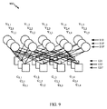
「リフティング」は、LDPCコードが、一般に、大きいLDPCコードに関連する複雑性をやはり低減させながら、並列符号化および/または復号実装形態を使用して実装されることを可能にする。リフティングは、比較的コンパクトな記述を依然として有しながら、LDPCデコーダの効率的な並列化を可能にするのに役立つ。より具体的には、リフティングは、より小さいベースコードの複数のコピーから比較的大きいLDPCコードを生成するための技法である。たとえば、リフトされたLDPCコードは、基本グラフ(たとえば、プロトグラフ)のZ個の並列コピーを生成し、次いで、基本グラフの各コピーのエッジバンドルの置換により並列コピーを相互接続することによって生成され得る。基本グラフは、コードの(マクロ)構造を定義し、ある数(K)の情報ビット列およびある数(N)のコードビット列からなる。基本グラフをリフティングの数Zだけリフトすることは、結果として、KZの最終ブロック長をもたらす。したがって、より大きなグラフは、基本グラフの複数のコピーが作られて接続されて、単一のリフトされたグラフを形成する「コピーおよび置換」動作によって取得され得る。複数のコピーの場合、単一の基本エッジのコピーのセットである同様のエッジが置換されて接続されて、基本グラフよりもZ倍大きな接続されたグラフZを形成する。 "Lifting" allows LDPC codes to be implemented using parallel encoding and/or decoding implementations, while also typically reducing the complexity associated with large LDPC codes. Lifting helps enable efficient parallelization of LDPC decoders while still having a relatively compact description. More specifically, lifting is a technique for generating a relatively large LDPC code from multiple copies of a smaller base code. For example, the lifted LDPC code is generated by generating Z parallel copies of a base graph (e.g., protograph) and then interconnecting the parallel copies by permuting the edge bundles of each copy of the base graph. obtain. The basic graph defines the (macro) structure of the code and consists of a certain number (K) of information bit strings and a certain number (N) of code bit strings. Lifting the basic graph by a number Z of liftings results in a final block length of KZ. Thus, a larger graph can be obtained by a "copy and replace" operation in which multiple copies of the base graph are made and connected to form a single lifted graph. In the case of multiple copies, similar edges, which are a set of copies of a single base edge, are permuted and connected to form a connected graph Z that is Z times larger than the base graph.
図9は、図8の2部グラフ800の3個のコピーのリフティングを示す2部グラフ900である。3個のコピーはコピー同士の間で同様のエッジを置換することによって相互接続され得る。置換が巡回置換に制限される場合、結果として生じる2部グラフ900はリフティングZ=3である準巡回LDPCに対応する。3個のコピーが作成された元のグラフは、本明細書では基本グラフと呼ばれる。異なるサイズのグラフを取得するために、「コピーおよび置換」動作を基本グラフに適用することができる。
FIG. 9 is a
ベースパリティチェック行列内の各エントリをZxZ行列と置換することによって、リフトされたグラフの対応するパリティチェック行列を基本グラフのパリティチェック行列から構築することができる。「0」エントリ(基本エッジを有さないエントリ)は0行列と置換され、1エントリ(基本エッジを示す)はZxZ置換行列と置換される。巡回リフティングの場合、置換は巡回置換である。 The corresponding parity check matrix of the lifted graph can be constructed from the parity check matrix of the base graph by replacing each entry in the base parity check matrix with a ZxZ matrix. The "0" entry (entry without a basic edge) is replaced with the 0 matrix, and the 1 entry (indicating the basic edge) is replaced with the ZxZ permutation matrix. In the case of cyclic lifting, the permutation is a cyclic permutation.
巡回リフトされたLDPCコードは、バイナリ多項式モジュロxz+1のリング上のコードと解釈することもできる。この解釈では、バイナリ多項式(x)=b0+b1x+b2x2+…+bz-1xz-1は、基本グラフ内の各変数ノードに関連付けられ得る。バイナリベクトル(b0,b1,b2,…,bz-1)は、リフトされたグラフ内のZ個の対応する変数ノード、すなわち、単一の基本変数ノードのZ個のコピーに関連するビットに対応する。バイナリベクトルのk(グラフ内のエッジに関連するリフティング値と呼ばれる)による巡回置換は、対応するバイナリ多項式をxkで乗算することによって達成され、この場合、乗算はモジュロxz+1をとる。基本グラフ内の次数dのパリティチェックは、隣接のバイナリ多項式B1(x),…,Bd(x)に対する線形制約と解釈することができ、

結果的に生じるこの式は、基本グラフ内の単一の関連するパリティチェックに対応する巡回リフトされたTannerグラフ内のZ個のパリティチェックに等しい。したがって、リフトされたグラフに関するパリティチェック行列は、1のエントリがxkの形の名目値と置換され、0のエントリが0としてリフトされる、基本グラフに関する行列を使用して表現可能であるが、ここで、0は、0バイナリ多項式モジュロxz+1と解釈される。そのような行列は、xkの代わりに値kを与えることによって書き込まれる。この場合、0の多項式は「-1」と表現されることがあり、それをx0と区別するために、別の記号として表現されることもある。 The resulting equation is equivalent to Z parity checks in the cyclic lifted Tanner graph corresponding to a single associated parity check in the base graph. Therefore, the parity-check matrix for the lifted graph can be expressed using the matrix for the basic graph, where 1 entries are replaced by nominal values of the form x k and 0 entries are lifted as 0. , Where 0 is interpreted as a 0 binary polynomial modulo x z +1. Such a matrix is written by giving the value k instead of x k . In this case, the polynomial of 0 may be expressed as “−1” and may be expressed as another symbol to distinguish it from x 0 .
一般に、パリティチェック行列の正方部分行列はコードのパリティビットを表す。相補列は、符号化の時点で、符号化されるべき情報ビットに等しく設定された情報ビットに対応する。符号化は、パリティチェック方程式を満たすために、前述の正方部分行列内の変数を求めることによって達成され得る。パリティチェック行列Hは、2つの部分MおよびNに区分することができ、この場合、Mは正方部分である。したがって、符号化はMc=s=Ndを求めることに帰着し、この場合、cおよびdはxを含む。準巡回コードまたは巡回リフトされたコードの場合、上記の代数はバイナリ多項式モジュロxz+1のリングに関する解釈され得る。準巡回である802.11LDPCコードの場合、符号化部分行列Mは、図10に示すように整数表現を有する。 In general, the square submatrix of the parity check matrix represents the parity bits of the code. The complementary columns correspond to the information bits set at the time of encoding equal to the information bits to be encoded. Encoding can be accomplished by finding the variables in the square submatrix described above to satisfy the parity check equation. The parity check matrix H can be partitioned into two parts M and N, where M is the square part. Therefore, the encoding results in finding M c =s=Nd, where c and d include x. For quasi-cyclic codes or cyclic lifted codes, the above algebra can be interpreted in terms of rings of the binary polynomial modulo x z +1. In the case of the quasi-cyclic 802.11 LDPC code, the coding submatrix M has an integer representation as shown in FIG.
受信LDPCコードワードを復号して、元のコードワードの再構築バージョンを生成することができる。誤りがない場合、または訂正可能な誤りの場合、復号を使用して、符号化された元のデータユニットを復元することができる。デコーダは、冗長ビットを使用して、ビット誤りを検出および訂正することができる。LDPCデコーダは、概して、局所計算を反復的に実行して、エッジとともに、2部グラフ800内のメッセージを交換して、着信メッセージに基づいてノードにおいて計算を実行することでこれらのメッセージを更新することによって、それらの結果を通すことによって動作する。これらのステップは、一般に、数回繰り返されてよく、メッセージパッシングステップと呼ばれることがある。たとえば、グラフ800内の各変数ノード810に、通信チャネルからの観測によって判定された関連ビットの値の推定を示す「ソフトビット」(たとえば、コードワードの受信ビットを表す)を最初に提供することができる。これらのソフトビットを使用して、LDPCデコーダは、それら、またはそれらのいくつかの部分をメモリから反復的に読み取り、更新メッセージ、またはそれらのいくつかの部分をメモリに再度書き込むことによって、メッセージを更新することができる。更新動作は、一般に、対応するLDPCコードのパリティチェック制約に基づく。リフトされたLDPCコードに対する実装形態では、同様のエッジ上のメッセージは並列で処理されることが多い。
The received LDPC codeword can be decoded to produce a reconstructed version of the original codeword. If there are no errors, or in the case of correctable errors, decoding can be used to recover the original encoded data unit. The redundant bits can be used by the decoder to detect and correct bit errors. The LDPC decoder generally performs local computations iteratively, exchanging messages in the
高速アプリケーション用に設計されたLDPCコードは、符号化動作および復号動作において高い並列性をサポートするために、大きいリフティング係数と比較的小さい基本グラフとを用いた準巡回構成を使用することが多い。より高いコードレート(たとえば、コードワード長に対するメッセージ長の比率)を有するLDPCコードは、比較的少ないパリティチェックを有する傾向がある。ベースパリティチェックの数が変数ノードの次数(たとえば、変数ノードに接続されたエッジの数)よりも小さい場合、基本グラフ内で、変数ノードは、2個以上のエッジによってベースパリティチェックのうちの少なくとも1つに接続される(たとえば、変数ノードは「ダブルエッジ」を有し得る)。ベースパリティチェックの数が変数ノードの次数(たとえば、変数ノードに接続されたエッジの数)よりも小さい場合、基本グラフ内で、変数ノードは、2個以上のエッジによってベースパリティチェックのうちの少なくとも1つに接続される。2個以上のエッジによって接続されたベース変数ノードおよびベースチェックノードを有することは、概して、並列ハードウェア実装のためには望ましくない。たとえば、そのようなダブルエッジは、同じメモリロケーションに対して複数の同時読取り動作および書込み動作を生じさせる可能性があり、これは、データコヒーレンシ問題を生み出す可能性がある。ベースLDPCコード内のダブルエッジは、単一の並列パリティチェック更新の間に、メモリロケーション内の同じソフトビット値の並列読取りを2度トリガし得る。したがって、両方の更新を適切に組み込むことができるように、メモリに再度書き込まれるソフトビット値を組み合わせるために、一般に、追加の回路が必要とされる。LDPCコード内のダブルエッジの除去することは、この過剰な複雑性の回避に役立つ。 LDPC codes designed for high speed applications often use a quasi-cyclic structure with large lifting coefficients and relatively small elementary graphs to support high parallelism in encoding and decoding operations. LDPC codes with higher code rates (eg, message length to codeword length ratio) tend to have relatively few parity checks. If the number of base parity checks is less than the degree of the variable node (for example, the number of edges connected to the variable node), then in the basic graph, the variable node is at least one of the base parity checks with two or more edges. Connected together (eg, variable nodes can have "double edges"). If the number of base parity checks is less than the degree of the variable node (for example, the number of edges connected to the variable node), then in the basic graph, the variable node is at least one of the base parity checks with two or more edges. Connected to one. Having a base variable node and a base check node connected by more than one edge is generally undesirable for parallel hardware implementations. For example, such double edges can cause multiple simultaneous read and write operations to the same memory location, which can create data coherency issues. A double edge in the base LDPC code may trigger a parallel read of the same softbit value in the memory location twice during a single parallel parity check update. Therefore, additional circuitry is generally required to combine the soft bit values that are rewritten to memory so that both updates can be properly incorporated. Eliminating double edges in the LDPC code helps avoid this excess complexity.
巡回リフティングに基づくLDPCコード設計は、多項式モジュロのリング上のコードがバイナリ多項式モジュロxZ+1であり得ると解釈することができ、式中、Zはリフティングサイズ(たとえば、準巡回コード内のサイクルのサイズ)である。したがって、そのようなコードの符号化は、しばしば、このリング内の代数的演算として解釈され得る。 LDPC code design based on cyclic lifting can be interpreted that the code on the ring of polynomial modulo can be the binary polynomial modulo x Z +1 where Z is the lifting size (e.g., the cycle in the quasi-cyclic code). Size). Therefore, the encoding of such codes can often be interpreted as algebraic operations within this ring.
標準的な非正規LDPCコードアンサンブル(次数分布)の定義では、Tannarグラフ表現内のすべてのエッジは統計的に相互交換可能であり得る。言い換えれば、単一の統計的同値類エッジが存在する。リフトされたLDPCコードのより詳細な議論は、たとえば、Tom RichardsonおよびRuediger Urbankeによる、2008年3月17日に出版された「Modern Coding Theory」という表題の書籍に見出すことができる。マルチエッジLDPCコードの場合、複数の同値類エッジが可能であり得る。標準的な非正規LDPCアンサンブル定義では、グラフ内のノード(可変と制約の両方)は、エッジ次数がベクトルであるマルチエッジタイプ設定では、それらの次数、すなわち、それらのノードが接続されるエッジの数によって指定されるが、その次数は、各エッジ同値類(タイプ)からのノードに独立して接続されたエッジの数を指定する。マルチエッジタイプアンサンブルは、有限数のエッジタイプからなる。制約ノードの次数タイプは、(非負)整数のベクトルであり、このベクトルの第i番目のエントリは、そのようなノードに接続された第i番目のタイプのソケットの数を記録する。このベクトルは、エッジ次数と呼ばれることがある。変数ノードの次数タイプは、(非負)整数のベクトルと見なされ得るが、この次数タイプは2つの部分を有する。第1の部分は、受信分布に関し、受信次数と呼ばれることになり、第2の部分はエッジ次数を指定する。エッジ次数は、制約ノードに関するのと同じ役割を果たす。エッジは、それらが同じタイプのソケットをペアリングするとして分類される。ソケットは同様のタイプのソケットとペアリングすべきであるという制約は、マルチエッジタイプ概念を特徴づける。マルチエッジタイプ記述では、異なるノードタイプは異なる受信分布を有し得る(たとえば、関連するビットは異なるチャネルを通過し得る)。 In the standard non-normal LDPC code ensemble definition, all edges in the Tannar graph representation may be statistically interchangeable. In other words, there is a single statistical equivalence class edge. A more detailed discussion of the lifted LDPC code can be found, for example, in the book entitled "Modern Coding Theory", published March 17, 2008, by Tom Richardson and Ruediger Urbanke. For a multi-edge LDPC code, multiple equivalence class edges may be possible. In the standard non-canonical LDPC ensemble definition, the nodes in the graph (both mutable and constraint) are vectored in edge order, so in a multi-edge type setting, their order, that is, the edges to which they are connected. Specified by a number, the degree specifies the number of edges independently connected to the node from each edge equivalence class (type). A multi-edge type ensemble consists of a finite number of edge types. The degree type of the constraint node is a vector of (non-negative) integers, the ith entry of this vector records the number of the ith type sockets connected to such node. This vector is sometimes called the edge order. The degree type of a variable node can be considered as a vector of (non-negative) integers, but this degree type has two parts. The first part will be called the reception order with respect to the reception distribution, and the second part specifies the edge order. Edge degree plays the same role as for constraint nodes. Edges are classified as they pair sockets of the same type. The constraint that sockets should be paired with sockets of a similar type characterizes the multi-edge type concept. In a multi-edge type description, different node types may have different reception distributions (eg, associated bits may pass through different channels).
パンクチャリングは、より短いコードワードを生み出すために、コードワードからビットを除去する行為である。したがって、パンクチャリングされた変数ノードは、実際に送信されていないコードワードビットに対応する。LDPCコード内の変数ノードのパンクチャリングは、チェックノードをやはり効果的に除去すると同時に、(たとえば、ビットの除去により)短縮コードを生成する。具体的には、パンクチャリングされるべき変数ノードが1の次数を有する、パンクチャリングされるべきビットを含む、LDPCコードの行列表現(そのような表現は、コードが適切であることを条件に行結合によって可能であり得る)の場合、変数ノードのパンクチャリングは、コードから関連ビットを除去し、グラフからその単一の隣接チェックノードを効果的に除去する。結果として、グラフ内のチェックノードの数は1だけ低減される。 Puncturing is the act of removing bits from a codeword to produce a shorter codeword. Therefore, the punctured variable nodes correspond to codeword bits that have not actually been transmitted. Puncturing the variable nodes in the LDPC code also effectively removes the check nodes while at the same time producing a shortened code (eg, by removing bits). Specifically, a matrix representation of an LDPC code, where the variable node to be punctured has a degree of one, and which contains the bits to be punctured (such representation is conditional on the code being suitable Puncturing, which may be possible by merging), removes the relevant bit from the code and effectively removes that single adjacent check node from the graph. As a result, the number of check nodes in the graph is reduced by 1.
図11は、本開示のいくつかの態様による、エンコーダを示す簡素化ブロック図である。図11は、ワイヤレス送信のための符号化メッセージを含む信号を提供するように構成され得る無線周波数(RF)モデム1150の一部分を示す簡素化ブロック図1100である。一例では、BS110(または、逆経路上のUE120)内の畳み込みエンコーダ1102は送信のためのメッセージ1120を受信する。メッセージ1120は、受信デバイス向けのデータおよび/もしくは符号化音声または他のコンテンツを含み得る。エンコーダ1102は、一般に、BS110または別のネットワークエンティティによって定義された構成に基づいて選択された好適な変調およびコーディング方式(MCS)を使用してメッセージを符号化する。エンコーダ1102によって生成される符号化ビットストリーム1122は、次いで、別個のデバイスもしくは構成要素であってよく、またはエンコーダ1102と一体型であってもよいパンクチャリングモジュール1104によって選択的にパンクチャされ得る。パンクチャリングモジュール1104は、ビットストリームが、送信に先立ってパンクチャされるべきか、またはパンクチャリングなしで送信されるべきかを判定することができる。ビットストリーム1122をパンクチャする判定は、ネットワーク条件、ネットワーク構成、RAN定義された選好に基づいて、かつ/または他の理由で行われ得る。ビットストリーム1122は、パンクチャリングパターン1112に従ってパンクチャされ、メッセージ1120を符号化するために使用され得る。パンクチャリングパターン1112は、以下でより詳細に説明するように。LDPCコード設計に基づき得る。パンクチャリングモジュール1104は、Txシンボル1126のシーケンスを生成するマッパ1106に出力1124を提供し、Txシンボル1126のシーケンスは、Txチェーン1108によって変調され、増幅され、さもなければ処理され、アンテナ1110を通して送信するためのRF信号1128が生成される。
FIG. 11 is a simplified block diagram illustrating an encoder according to some aspects of the disclosure. FIG. 11 is a simplified block diagram 1100 that illustrates a portion of a radio frequency (RF)
モデム部分1150がビットストリーム1122をパンクチャするように構成されるかどうかに応じて、パンクチャリングモジュール1104の出力1124は、非パンクチャリングされたビットストリーム1122、またはビットストリーム1122のパンクチャリングされたバージョンであってよい。一例では、パリティおよび/または他の誤り訂正ビットは、RFチャネルの限定された帯域幅内でメッセージ1120を送信するために、エンコーダ1102の出力1124内でパンクチャされ得る。別の例では、ビットストリーム1122は、干渉を回避するために、または他のネットワーク関連の理由で、メッセージ1120を送信するために必要とされる電力を低減するためにパンクチャされ得る。これらのパンクチャリングされたコードワードビットは送信されない。
Depending on whether the
デコーダおよびLDPCコードワードを復号するために使用される復号アルゴリズムは、エッジとともにグラフ内のメッセージを交換して、着信メッセージに基づいてノードにおいて計算を実行することでこれらのメッセージを更新することによって動作する。グラフ内の各変数ノードに、たとえば、通信チャネルからの観測によって判定された関連ビットの値の推定を示す、受信値と呼ばれるソフトビットを最初に提供することができる。理想的には、別個のビットに関する推定値は統計的に独立している。この理想は、実際にはそむかれる。受信ワードは、受信値の収集物からなる。 The decoder and the decoding algorithm used to decode LDPC codewords work by exchanging messages in the graph with edges and updating these messages by performing computations at the node based on the incoming message. To do. Each variable node in the graph may first be provided with a soft bit, called the received value, which indicates, for example, an estimate of the value of the associated bit as determined by observation from the communication channel. Ideally, the estimates for the separate bits are statistically independent. This ideal is actually defeated. The received word consists of a collection of received values.
図12は、本開示のいくつかの態様によるデコーダを示す簡素化ブロック図である。図12は、パンクチャリングされた符号化メッセージを含む、ワイヤレスに送信された信号を受信および復号するように構成され得るRFモデム1250の一部分を示す簡素化概略図1200である。パンクチャコードワードビットは消去されるとして扱われてよい。たとえば、パンクチャリングされたノードのLLRは初期化において「0」に設定され得る。デパンクチャリングはまた、短縮ビットの短縮解除を含み得る。これらの短縮ビットは、送信内に含まれず、受信機において、短縮ビットは、一般に「0」に設定される、知られているビットとして扱われ、LLRの大きさが最大可能値に設定されることを可能にする。様々な例では、信号を受信するモデム1250は、アクセス端末(たとえば、UE120)に、基地局(たとえば、BS110)に、または説明する機能を実行するための任意の他の適切な装置もしくは手段に存在し得る。アンテナ1202はRF信号1220を受信機に提供する。RFチェーン1204は、RF信号1220を処理および復調し、シンボル1222のシーケンスをデマッパ1206に提供することができ、デマッパ1206は符号化メッセージ(たとえば、メッセージ1120)を表すビットストリーム1224を生成する。
FIG. 12 is a simplified block diagram illustrating a decoder according to some aspects of the present disclosure. FIG. 12 is a simplified schematic diagram 1200 illustrating a portion of an RF modem 1250 that may be configured to receive and decode wirelessly transmitted signals that include punctured encoded messages. Puncture codeword bits may be treated as erased. For example, the LLR of a punctured node may be set to "0" at initialization. Depuncturing may also include de-shortening the shortened bits. These shortened bits are not included in the transmission and at the receiver the shortened bits are treated as known bits, generally set to "0", and the LLR magnitude is set to the maximum possible value. To enable that. In various examples, the modem 1250 receiving the signal may be an access terminal (e.g., UE 120), a base station (e.g., BS 110), or any other suitable device or means for performing the described functions. Can exist
デマッパ1206はデパンクチャリングされたビットストリーム1224を提供することができる。一例では、デマッパ1206は、パンクチャリングされたビットが送信機によって削除されたビットストリーム内のロケーションにヌル値を挿入するように構成され得るデパンクチャリングモジュールを含み得る。送信機においてパンクチャリングされたビットストリームを生成するために使用されるパンクチャパターン1210が知られているとき、デパンクチャリングモジュールを使用することができる。パンクチャパターン1210を使用して、畳み込みデコーダ1208によってビットストリーム1224の復号の間に無視され得るLLR1228を識別することができる。LLRはビットストリーム1224内のデパンクチャビットロケーションのセットに関連付けられ得る。したがって、デコーダ1208は、識別されたLLR828を無視することによって処理オーバーヘッドを低減させて復号メッセージ1226を生成することができる。LDPCデコーダは、パリティチェック動作または変数ノード動作を並列で実行するための複数の処理要素を含み得る。たとえば、リフティングサイズZでコードワードを処理するとき、LDPCデコーダは、いくつか(Z個)の処理要素を利用して、リフトされたグラフのすべてのエッジ上でパリティチェック動作を同時に実行することができる。
The
デコーダ1208の処理効率は、パンクチャリングされたビットストリーム1222内で送信されたメッセージ内のパンクチャリングされたビットに対応するLLR1228を無視するようにデコーダ1208を構成することによって改善され得る。パンクチャリングされたビットストリーム1222は、符号化メッセージから除去されるべきいくつかのビットを定義するパンクチャリング方式に従ってパンクチャされている場合がある。一例では、いくつかのパリティビットまたは他の誤り訂正ビットを除去することができる。パンクチャリングパターンは、各メッセージ内のパンクチャされるべきビットのロケーションを識別するパンクチャリング行列またはパンクチャリング表の形で表現され得る。通信チャネル上のデータレートおよび/またはネットワークによって設定された送信電力制限に準拠したままでありながら、メッセージ1226を復号するために使用される処理オーバーヘッドを低減させるためのパンクチャリング方式を選択することができる。結果として生じるパンクチャリングされたビットストリームは、一般に、高レートの誤り訂正コードの誤り訂正特性を示すが、冗長性はより小さい。したがって、チャネル条件が雑音比(SNR)に対して比較的高い信号を生成するとき、受信機内のデコーダ1208における処理オーバーヘッドを低減させるためにパンクチャリングを効果的に採用することができる。
The processing efficiency of the
いくつのビットがパンクチャされているかにかかわらず、受信機において、パンクチャリングされたビットストリームを復号するために、非パンクチャリングされたビットストリームを復号するために使用される同じデコーダを一般に使用することができる。従来の受信機では、一般に、パンクチャリングされた状態またはパンクチャリングされた位置に関するLLR(デパンクチャリングされたLLR)をゼロで充填することによって復号が試みられる前に、LLR情報がデパンクチャされる。デコーダは、何のビットがパンクチャリングされているかに部分的に基づいて、何の情報も効果的に搬送しないデパンクチャリングされたLLRを無視することができる。デコーダは、短縮ビットを(たとえば、「0」に設定された)知られているビットとして扱うことができる。 At the receiver, regardless of how many bits are punctured, generally use the same decoder that is used to decode the non-punctured bitstream to decode the punctured bitstream. You can In conventional receivers, LLR information is generally depunctured before decoding is attempted by zero filling the LLRs (depunctured LLRs) for the punctured state or punctured position. The decoder can ignore depunctured LLRs that do not effectively carry any information, based in part on which bits are punctured. The decoder can treat the shortened bits as known bits (eg, set to "0").
例示的な高性能、フレキシブル、かつコンパクトな低密度パリティ検査(LDPC)コード
本開示のいくつかの態様は、高性能を与え、フレキシブル、かつコンパクトな低密度パリティ検査(LDPC)コード設計を提供する。以下でより詳細に説明するように、LDPCコードは、ファインインクリメンタル冗長ハイブリッド自動再送要求(IR-HARQ)拡張が可能であり、良好なエラーフロア性能、高いスループット性能に対するハイレベルの並列性、および低い記述複雑性を維持しながら、広範囲のコードレート、ブロック長、および粒度のために使用され得る。
Exemplary High Performance, Flexible, and Compact Low Density Parity Check (LDPC) Codes Several aspects of the present disclosure provide high performance, flexible, and compact low density parity check (LDPC) code designs. .. As described in more detail below, the LDPC code is fine incremental redundant hybrid automatic repeat request (IR-HARQ) extendable, with good error floor performance, high level of parallelism for high throughput performance, and low It can be used for a wide range of code rates, block lengths, and granularities, while maintaining description complexity.
LDPCコードを効率的にリフトするための例示的な独立クラスタリング方式
ワイヤレス通信システム(たとえば、ワイヤレス通信システム100)では、たとえば、使用されるべき様々な範囲のブロック長および/またはコードレートに対して、エラー訂正コード(たとえば、LDPCコード)のセットが使用され得る。記述の実装およびコンパクト性の点で効率を高めるために、コードのセットが関係づけられることが望ましい。
Exemplary Independent Clustering Scheme for Efficiently Lifting LDPC CodesIn a wireless communication system (e.g., wireless communication system 100), for example, for various ranges of block lengths and/or code rates to be used, A set of error correction codes (eg LDPC codes) may be used. For efficiency in terms of implementation and compactness of the description, it is desirable for the sets of code to be related.
図9に関して上記で説明したように、リフトされたLDPCコードを提供するために、基本グラフまたはパリティチェック行列(PCM)(K個の情報ビット列およびN個の総送信ビット列を有する)をコピーすることができ、任意の置換を各エッジバンドルに適用して、それらのコピーを相互接続することができる。実際的なコードは、巡回置換または循環置換行列を使用して、リフトされた基本グラフのコピーを相互接続し、結果として、ハードウェアにおける実装がより容易であり得る、準巡回コードをもたらす。一例として、リフティング値Zの場合、ベースPCM内の各エッジは、範囲[0,Z-1]内の整数リフティング値kに関連し得る。関連する整数は、その整数による単位行列の巡回シフトを表す。ビット列およびチェックノードに対するエントリを示すベースPCMに関する表を使用することができる。各エントリは、変数ノードとチェックノードとの間のエッジに関連する整数値によって巡回シフトされた単位行列である循環行列に対応する。ベース変数ノードとベースチェックノードとの間にエッジが存在しないとき、エントリ「.」が使用され得る。 Copying a basic graph or parity check matrix (PCM) (with K information bit strings and N total transmitted bit strings) to provide a lifted LDPC code, as described above with respect to FIG. 9. And any permutations can be applied to each edge bundle to interconnect their copies. Practical code uses cyclic permutations or circular permutation matrices to interconnect copies of the lifted elementary graph, resulting in quasi-cyclic code that may be easier to implement in hardware. As an example, for a lifting value Z, each edge in the base PCM may be associated with an integer lifting value k in the range [0,Z-1]. The associated integer represents the cyclic shift of the identity matrix by that integer. A table can be used for the base PCM showing the entries for the bitstreams and check nodes. Each entry corresponds to a circular matrix that is an identity matrix that is cyclically shifted by the integer value associated with the edge between the variable node and the check node. The entry "." may be used when there is no edge between the base variable node and the base check node.
変更なしに基本グラフが再使用されるとき、(K/Nによって与えられる)コードレートは(リフティングの数または基本グラフのコピーの数に対応する)すべてのリフティングZに関して同じである。異なるリフティング値を使用することは、(KZによって与えられる)ある範囲のブロック長を達成するためにコードのセット(たとえば、コードファミリー)を提供し得る。したがって、変更されていない基本グラフに関して異なるリフティング値を使用することは、同様のコードレートを有するが、異なるブロック長に関する、コードのセットを達成し得る。異なるコードレートに関して、異なる基本グラフが使用され得る。 When the basic graph is reused without modification, the code rate (given by K/N) is the same for all lifting Z (corresponding to the number of liftings or the number of copies of the basic graph). Using different lifting values may provide a set of codes (eg, code families) to achieve a range of block lengths (given by KZ). Therefore, using different lifting values for the unchanged basic graph may achieve a set of codes with similar code rates but different block lengths. Different basic graphs may be used for different code rates.
コードレートの範囲および/またはブロック長に対するコードのセット(たとえば、コードファミリー)を生成/記述するためにコードファミリーを設計する1つの方法は、各コードレートおよび各リフト値に対して異なるベースPCMを設計することである。たとえば、802.11nでは、(27, 54, 81)のリフト値に対応する、4個のコードレート(1/2、2/3、3/4、5/6)および3個のブロック長(648、1296、1944)が存在する。各「タプル」(すなわち、コードレートとリフト値の各対)に関してサイズ24ビット列の一意のベースPCMが存在し、結果として、(たとえばコードレートおよびリフト値の組合せ(1/2, 27)、(1/2, 54)、(1/2, 81)、…(5/6, 81)に関して)12個のベースPCMをもたらす。したがって、大きなZの場合、リフティングZとリフティング値Kのセットは大きな記述複雑性をもたらし得る。
One way to design a code family to generate/describe a set of codes (e.g. code family) for a range of code rates and/or block lengths is to use different base PCM for each code rate and each lift value. It is to design. For example, in 802.11n, four code rates (1/2, 2/3, 3/4, 5/6) and three block lengths (648) correspond to lift values of (27, 54, 81). , 1296, 1944) exist. There is a unique base PCM of
リフティングのセットを効率的に記述/生成するための技法が望ましい。 Techniques for efficiently describing/generating a set of lifting are desirable.
単一のパリティ行列に関するリフティングのセットは、値の点で互いに間隔が密な増大された一連のリフティングとして効率的に記述され得る。これは、リフティングが、ビットの共通セットを有する狭い範囲内で指定されることを可能にし、コンパクトな記述および良好な性能を可能にする。 A set of liftings for a single parity matrix can be efficiently described as an increasing series of liftings that are closely spaced to each other in terms of value. This allows lifting to be specified within a narrow range with a common set of bits, allowing a compact description and good performance.
図13は、本開示のいくつかの態様による、基本グラフ構造を使用してコードワードを符号化および送信するための例示的な動作1300を示す流れ図である。動作1300は、たとえば、送信機/エンコーダデバイス(たとえば、BS110またはUE120)によって実行され得る。動作1300は、1302において、基底行列を判定することによって開始する。基底行列は、リフティングサイズ値のクラスタに関連する。1304において、送信機デバイスは、基底行列内のエッジの置換によってリフトされたLDPCコードを生成するために、リフティングサイズ値Zを選択する。リフティングサイズ値のクラスタ内のリフティングサイズ値は、互いの定義された範囲内である。1306において、送信機デバイスは、基底行列および選択されたリフティングサイズ値に少なくとも部分的に基づいて、リフトされた行列を生成する。1308において、送信機デバイスは、生成されたリフトされた行列を使用して、リフトされたLDPCコードを生成する。1310において、送信機デバイスは、コードワードを生成するために、リフトされたLDPCコードに基づいて情報ビットのセットを符号化する。1312において、送信機デバイスは、ワイヤレス媒体を介してコードワードを送信する。
FIG. 13 is a flow diagram illustrating an
本開示の態様によれば、LDPCコードのファミリーを取得するための、単一の基本グラフまたはPCMに関するリフティングZのセットは、コンパクトな記述のために値の点で互いに近いリフティング値を使用して記述され(たとえば、判定され/生成され)得る。 In accordance with aspects of the present disclosure, a set of lifting Zs for a single elementary graph or PCM to obtain a family of LDPC codes uses lifting values that are close in value to each other for compact description. It may be described (eg, determined/generated).
LDPCコードのファミリーは、本明細書でリフティングの「タワー」と呼ばれることがある、リフティング値Z1、Z2、…、Znを用いた増大された一連のリフティングとともに基本グラフを使用して取得され得る。クラスタは、互いの定義された範囲内であるメンバーを含む。たとえば、クラスタのメンバーは、互いの一定の比率内であり得る。場合によっては、クラスタのメンバーの値は、互いの2の比率内であり得る。 The family of LDPC codes is obtained using a basic graph with an increased series of liftings with lifting values Z 1 , Z 2 ,..., Z n , sometimes referred to herein as lifting “towers”. Can be done. A cluster includes members that are within a defined range of each other. For example, the members of the cluster may be within a certain ratio of each other. In some cases, the values of the members of the cluster may be within a 2 ratio of each other.
クラスタの一例は、7/4の最大比率を有するリフティング値のセット{4, 5, 6, 7}である。タワーは、2の冪など、指数冪(exponential power)を整数に施すことによって取得され得る。したがって、クラスタ化されたリフティングのタワーは、j=1,…,7の場合、整数2j{4,5,6,7}からなる。これは、Zに関する28個の値のほぼ指数関数的に離間したセットを与える。言い換えれば、これは、タワーZ1、Z2、…、Z28=8(21*4)、10、12、14、…、896(27*7)を与える。固定されたjの場合、4個のリフティング値は、互いの7/4の因数内であり、リフティング値のクラスタを形成し得る。j=1、...、7の場合、クラスタ化されたリフティングのタワーは、2j{4,5,6,7}として表すことができる。この例は、クラスタ化されたとして2の因数内のリフトのセットを含むが、他の因数(たとえば、3、4、…、など)が使用され得る。これらの因数は連続的でなくてよいが、数値的に互いの定義された範囲内にあるべきである。 An example of a cluster is the set of lifting values {4, 5, 6, 7} with a maximum ratio of 7/4. The tower can be obtained by subjecting an integer to an exponential power, such as a power of two. Thus, the clustered lifting tower consists of the integers 2 j {4,5,6,7} for j=1,...,7. This gives a nearly exponentially spaced set of 28 values for Z. In other words, this gives the towers Z 1 , Z 2 ,..., Z 28 =8(2 1 *4), 10, 12, 14,..., 896 (2 7 *7). For a fixed j, the four lifting values are within 7/4 of each other and may form a cluster of lifting values. For j=1,...,7, the tower of clustered lifting can be represented as 2 j {4,5,6,7}. This example includes a set of lifts within a factor of 2 as clustered, but other factors (eg, 3, 4,..., And so on) can be used. These factors need not be contiguous, but should be numerically within each other's defined range.
いくつかの態様によれば、クラスタ化されたリフティングのセット内の任意のリフティングサイズZの場合、クラスタ化されたリフティングのセット内の他のリフティングのいずれかに対するエッジ置換に対して関連する整数リフティング値kを使用することができる。たとえば、リフティング値は、2j{5,6,7}に対しても有効であるZ=2j4に対して設計され得る。したがって、LDPCコードのファミリーを記述すること(たとえば、判定すること/生成すること/示すこと/記憶すること)は、互いの因数(たとえば、因数2または3)内など、互いと近いクラスタ化された(基本グラフ内のエッジに関連する)リフト値のセットを識別することによって実施され得る。上記の例では、これは、リフティング値のセット{4,5,6,7}、および互いの2の因数内である、リフティングのタワーの他のセット{16,20,24,28}、{32,40,48,56}、…{512,640,768,896}を識別することに対応する。リフティングの各クラスタ化されたセットに関して、クラスタ内の最小リフト値(たとえば、Z=8)に関するベースPCMを最適化することができる。その最適化されたベースPCMをそのクラスタ内の他のリフト値(たとえば、Z=10、Z=12、Z=14)に対して使用することができる。同様に、クラスタ化されたリフティングの他のセットに関して最適化されたベースPCMを判定することができる。
According to some aspects, for any lifting size Z in the set of clustered lifting, the associated integer lifting for edge permutation to any of the other liftings in the set of clustered lifting. The value k can be used. For example, the lifting value can be designed for Z=2 j 4, which is also valid for 2 j {5,6,7}. Therefore, describing (e.g., determining/generating/indicating/memorizing) a family of LDPC codes is clustered close to each other, such as within each other's factors (e.g.,
これにより、互いの定義された範囲内のリフティングがビットの共通セットを有する他のリフティングに関して指定(たとえば、記憶され/示され)得る。たとえば、リフティング値ごとにj+2ビットを使用して、クラスタ内の4つの述べたリフティング2j{4,5,6,7}に対するすべてのリフトを指定することができる。 This allows lifting within a defined range of each other to be specified (eg, stored/indicated) with respect to other liftings that have a common set of bits. For example, j+2 bits for each lifting value can be used to specify all lifts for the four mentioned lifting 2 j {4,5,6,7} in the cluster.
これらのリフティングは、追加のビットを有することによってさらに改善され得る。たとえば、エッジ上のリフティング値kを表すためにj+3ビット使用し、2j{4,5,6,7}内のZに関してj+3ビット値モジュロZを利用することによってリフティングを定義することは、結果として、j+2より低次のビットおよびより高次のビットが他の3個のリフティングのみに影響を与えることによって、Z=2j*4に対するリフティングをもたらす。より高次のビットを同様に使用することができる。この例は、互いの因数内のリフティング範囲を表し、すべてj+2(または、より若干大きな)ビットを使用して指定される。しかしながら、因数が数値的に互いの定義された範囲内にある限り、他の因数を使用することができる。 These liftings can be further improved by having an additional bit. For example, use j+3 bits to represent the lifting value k on an edge, and define lifting by taking the j+3 bit value modulo Z with respect to Z in 2 j {4,5,6,7} This results in lifting for Z=2 j *4, with bits lower and higher than j+2 affecting only the other three liftings. Higher order bits can be used as well. This example represents lifting ranges within each other's factors, all specified using j+2 (or slightly larger) bits. However, other factors can be used as long as the factors are numerically within the defined range of each other.
概して、リフトおよびグラフの最適化は、LDPCコードのTannerグラフ内の小型ループの数を低減することを目標とする。リフトされたTannerグラフ内のループは、ループを基本グラフ上に投影することによる基本グラフ内のループに対応する。追加の最適化は、ループ内のノードの次数を考慮に入れることができる。整合されたリフトされたグラフ(たとえば、巡回リフトされたグラフ)の場合、基本グラフ内のループはまた、ループ内でトラバースするリフティング値が恒等置換に簡約化するときにまさにリフトされたTannerグラフのループである。 In general, lift and graph optimization aim to reduce the number of small loops in the Tanner graph of LDPC code. The loops in the lifted Tanner graph correspond to the loops in the basic graph by projecting the loop onto the basic graph. Additional optimizations can take into account the order of the nodes in the loop. In the case of a matched lifted graph (for example, a cyclic lifted graph), the loops in the base graph are also just lifted Tanner graphs when the lifting values traversing in the loop reduce to identity permutation. Is a loop.
いくつかの態様によれば、リフティングを表すためにj+3ビット使用し、2j{4,5,6,7}内のZに対してj+3ビット値モジュロZを利用することによってリフティングを定義することは、結果として、j+2より低次のビットおよびより高次のビットが他の3個のリフティングのみに影響を与えることによって、Z=2j4に対するリフティングをもたらす。 According to some aspects, using j+3 bits to represent lifting, and lifting by taking the j+3 bit value modulo Z for Z in 2 j {4,5,6,7} be defined as a result, by j + 2 lower order bits and higher bits only affect other three lifting leads to lifting for Z = 2 j 4.
クラスタ化されたリフティングのセットに対する基本グラフの最適化の場合、範囲[0,(2j*4)-1]内のリフティング値を選択することができる。言い換えれば、クラスタ化されたリフティングのセット内の最小リフティングサイズよりも小さい範囲からリフティング値を選択することができる。したがって、本明細書で説明する例では、j=1に対して、クラスタ化されたリフティングのタワーの場合、範囲[0:7]からリフティングサイズ値を選択することができる。 For the optimization of the basic graph for a set of clustered lifting, we can choose lifting values in the range [0,(2 j *4)-1]. In other words, the lifting value can be selected from a range smaller than the minimum lifting size within the set of clustered liftings. Therefore, in the example described herein, for j=1, in the case of a clustered lifting tower, lifting size values can be selected from the range [0:7].
巡回リフトされたグラフの場合、基本グラフ内の各エッジはリフティング値として関連する整数を有する。値は、エッジが変数対チェック方向にトラバースするとき正と見なされ、チェック対変数方向にトラバースするとき負と見なされる。基本グラフ内のループおよびリフティングサイズZを鑑みて、対応する整数のループ和(loop sum)が0であるかまたは因数としてZを有する場合、ベースループはまた、リフトされたループになる。したがって、リフティング値に対して範囲[0,2j4]内で整数値を選定するとき、Z=2j4に対する目標は、和が0になることまたはループ和において2j4の因数を有することを回避することである。小型ループの場合、和は、一般に、大きくならず、したがって、概して、大きさの和が2*2j4または3*2j4である場合よりも、大きさの和が2j4である場合にそのようなループがより多く存在する。同様に、平均して、大きさの和2j{5, 6, 7}およびその倍数の頻度はより低い。したがって、小型ループ回避設計問題は、範囲[0:2j 4]内のリフト値がZ=2j{5,6,7}の場合に利用可能な範囲の半分を超える範囲を使用する、これらの密に関係する値と同様である。はるかに大きなZの場合、使用される部分はより小さくなり、大きなZに関して利用可能な最高性能とリフティングをより小さなZに制限することによって達成可能な最高性能との間により大きなギャップが存在し得る。したがって、比較的小さな範囲の(たとえば、2の因数内の)Z値に対してこの手法を適用することが賢明である。したがって、4個の値に対して良好な性能を同時に与えるリフト値を見出すことは可能である。 For a cyclic lifted graph, each edge in the base graph has an associated integer as a lifting value. The value is considered positive when the edge traverses in the variable-to-check direction and negative when traversing in the check-to-variable direction. Given the loops and lifting size Z in the basic graph, the base loop will also be a lifted loop if the corresponding integer loop sum is 0 or has Z as a factor. Therefore, when choosing an integer value in the range [0,2 j 4] for the lifting value, the goal for Z=2 j 4 is that the sum is 0 or has a factor of 2 j 4 in the loop sum. It is to avoid that. For small loop, the sum will generally not increased, therefore, generally, than the sum of the sizes is 2 * 2 j 4 or 3 * 2 j 4, the sum of the sizes is a 2 j 4 There are more such loops in some cases. Similarly, on average, the sum of magnitudes 2 j {5, 6, 7} and its multiples are less frequent. Therefore, the small loop avoidance design problem is that these lifts in the range [0:2 j 4] use more than half the range available when Z=2 j {5,6,7}. Similar to the closely related value of. For much larger Z, the portion used will be smaller and there may be a larger gap between the best performance available for a larger Z and the best performance achievable by limiting lifting to a smaller Z. .. Therefore, it is prudent to apply this approach to Z values in a relatively small range (eg, within a factor of 2). Therefore, it is possible to find a lift value that gives good performance for four values at the same time.
j=1、…、7の場合、各jに関するビットの独立したセットとともに数値的に定義された範囲内にあるリフティングの範囲を利用することによって、リフティングのすべてを指定するために必要とされるビットの数は、エッジごとに3+4+5+6+7+8+9=42ビットである。jの異なる値同士の間に依存性を生み出すことによって、この要件はさらに低減され得る。加えて、多くの場合、構造化LDPCグラフはそのリフティング値が直接的に判定され得る特殊なエッジを有することになる。たとえば、次数1の変数ノードを接続するエッジは、常に、リフティング値0を有し得る。符号化構造で累積チェーン上のエッジはやはり、多くの場合、0に設定される。そのような固定されたリフティング構造は、リフティングが変化するにつれて変化しない場合があり、特殊な不変構造を有すると言われることがある。そのようなエッジに関するリフティング値は、よりコンパクトに表すことができる。しかしながら、そのような特殊な不変構造を有するエッジの数は、グラフ内のエッジの総数のごく一部であり、特殊な不変構造を有さないエッジに対して上記の方法の恩恵をあまり損ねない。
For j=1,...,7, it is required to specify all of the liftings by utilizing the range of liftings that is within a numerically defined range with an independent set of bits for each j The number of bits is 3+4+5+6+7+8+9=42 bits per edge. By creating a dependency between different values of j, this requirement can be further reduced. In addition, often structured LDPC graphs will have special edges whose lifting values can be directly determined. For example, edges connecting variable nodes of
LDPCコードを効率的にリフトするための例示的なネスト型方式
上記で説明したように、リフティングのクラスタ化されたセット(たとえば、リフティングの「タワー」)内のリフティングは、同じリフティング値(エッジ置換に関連する整数)を使用してよく、したがって、リフティングおよびリフティング値のすべてを指定するために使用されるビットの数を低減し得る。このサイズ低減は、LDPCコードのすべての記述を記憶するためのメモリの量を低減させることを可能にし得る。
Exemplary Nested Schemes for Efficient Lifting of LDPC CodesAs explained above, lifting within a clustered set of liftings (e.g., a lifting "tower") is done with the same lifting value (edge replacement). Associated integer) may be used, thus reducing the number of bits used to specify all lifting and lifting values. This size reduction may allow reducing the amount of memory for storing all descriptions of LDPC code.
本開示の態様によれば、ベースPCM内のエッジごとのビットの数をさらに低減する、LDPCコードを効率的にリフトするためのネスト方式を使用することができる。 According to aspects of the present disclosure, a nesting scheme for efficiently lifting LDPC codes that further reduces the number of bits per edge in the base PCM can be used.
異なるj値(たとえば、異なるクラスタ化されたセット内のリフティング)に関してすら、すべてのリフティングは同じ基本グラフに基づくため、小さなj値に関して(すなわち、クラスタ化されたリフティングの対応するセット内のリフティングに関して)機能することが見出された構造をスケーリングして、より大きなj値に関して(すなわち、別のセット内のより大きなリフティングに関して)再使用することができる。たとえば、より小さなjに関して見出された最適化されたビットを再使用するために、より小さなjに関して最適化された構造を保持して、より大きなjに関してスケーリングすることができる。 Even for different j-values (e.g. lifting in different clustered sets), all liftings are based on the same basic graph, so for small j-values (i.e. for liftings in the corresponding set of clustered liftings). The structures found to work can be scaled and reused for larger j-values (ie for larger liftings in another set). For example, in order to reuse the optimized bits found for smaller j, we can keep the optimized structure for smaller j and scale for larger j.
図14は、本開示のいくつかの態様による、基本グラフ構造を使用してコードワードを符号化および送信するための例示的な動作1400を示す流れ図である。動作1400は、たとえば、送信機/エンコーダデバイス(たとえば、BS110またはUE120など)によって実行され得る。動作1400は、1402において、基底行列を判定することによって開始する。基底行列は、リフティングサイズ値のクラスタに関連する。1404において、送信デバイスは、基底行列内のエッジの置換によってリフトされた低密度パリティ検査(LDPC)コードを生成するために、リフティングサイズのクラスタから第1のリフティングサイズ値Zを選択する。リフティングサイズ値のクラスタ内のリフティングサイズ値は、互いの定義された範囲内である。1406において、送信デバイスは、基底行列および選択された第1のリフティングサイズ値に少なくとも部分的に基づいて、第1のリフトされた行列を生成する。1408において、送信デバイスは、選択された第1のリフティングサイズ値に関連するビットのセットを選択する。1410において、送信デバイスは、リフティングサイズ値のクラスタから第2のリフティングサイズ値を選択する。1412において、送信デバイスは、基底行列、第2の選択されたリフティングサイズ値、およびビットのセットに少なくとも部分的に基づいて、第2のリフトされた行列を生成する。1414において、送信デバイスは、生成された第2のリフトされた行列を使用して、リフトされたLDPCコードを生成する。1416において、送信デバイスは、コードワードを生成するために、リフトされたLDPCコードに基づいて情報ビットのセットを符号化する。1418において、送信デバイスはコードワードを送信する。上記で説明した例では、j=1の場合、クラスタ化されたリフティングのセットZ={8,10,12,14}は、範囲[0,1,2,…7]内のリフティング値を使用して設計され得る。いくつかの態様によれば、j=1のグラフに関して選択されるリフティング値を、2で乗算し、j=2のグラフに関して使用することができ、ここで、クラスタ化されたリフティングのセットはZ={16,20,24,28}である。この場合、より大きなリフトされたグラフ(j=2の場合)が継承し、より小さなグラフのループ構造を改善するが、これは、リフティング2Zに関するより大きなブラフがリフティングZを有する元のより小さなグラフの2個の並列コピーからなるためである。より小さなグラフはループが加算されてZの因数になるのを回避するように設計されるため、より小さいグラフはループが加算されて2Zの因数になることも回避する。j=1およびj=2は、単なる例示である。態様では、より大きなクラスタ化されたリフティングの別のセットに関してクラスタ化されたリフティングの任意のセットに関するリフティング値を使用することができ、リフティング値に、リフティングの2つのセットのリフティングサイズの差分の係数を乗じることができる。
FIG. 14 is a flow diagram illustrating an
リフティング内の最低次ビットを変更することによって、より大きなグラフのさらなる最適化を達成することができる。たとえば、2による乗算の後で、すべてのリフティングは、それらの最低次ビットを0に設定させることになる。より一般的には、考えられる最高性能を達成するために、単なる最低次ビットを上回るビットを変更することができる。たとえば、2個または3個の最下位ビットを変更することができる。概して、3個の最下位ビットを最適化することは、結果として、ほぼ最適な性能をもたらす。これは、(2で乗算することによって)それに応じてスケールアップされた、リフティング(最上位)ビットの大規模な属性を保ち、次いで、細部(より低次のビット)を微細化して、クラスタ化されたリフティングの次のセットに対する基本グラフに対する最適なソリューションを見出す。 Further optimization of larger graphs can be achieved by changing the lowest order bit in the lifting. For example, after multiplication by 2, all liftings will have their lowest order bit set to 0. More generally, more than just the lowest order bit can be modified to achieve the highest possible performance. For example, two or three least significant bits can be modified. In general, optimizing the three least significant bits results in near-optimal performance. This keeps the large attributes of the lifting (most significant) bits scaled up accordingly (by multiplying by 2), then refines the details (lower order bits) into clustering. Find an optimal solution to the basic graph for the next set of lifted lifts.
一例では、3個の最低次ビットを再度最適化することができる。クラスタ化されたリフティングのセットj=1に関して、エッジごとに3ビットの最適化されたリフトを取得することができる。ベース2(base 2)内の基本グラフ内のエッジに関する(たとえば、セットj=1内の最小リフティングに関する)リフティング値が、a、y、およびz(すなわち、3ビット)である(すなわち、a、y、およびzの各々が0または1の整数値である)場合、クラスタ化されたリフティングのセットj=2に対する基本グラフに関して、同じエッジはa、b、w、x,のリフティング値(すなわち、1ビットがj=1ファミリーからコピーされた4ビット)を有し、クラスタ化されたリフティングのセットj=3に対する基本グラフにおいて、エッジは、リフティング値a、b、c、u、v(2ビットがj=2ファミリーからコピーされた5ビット)を有する、等々である。したがって、クラスタ化されたリフティングのセットj=7に対する基本グラフにおいて、エッジは、リフティング値a、b、c、d、e、f、g、r、s(すなわち、7ビットがj=6ファミリーからコピーされた9ビット)を有することになり、クラスタ化されたリフティングのより小さなセットjに関してビットa、b、c、d、e、f、gが再使用され、ビットrおよびsはj=7に対して一意である。クラスタ化されたリフティングのセットに対する基本グラフは、j個の共通ビットおよび2個の一意ビットを使用する。したがって、ファミリーj=1…7のすべてに対して、すべての7個のコードファミリーを記述するための合計21ビットに対して、合計で7個の共通ビットおよび14個の一意ビット(すなわち、各jに対して2個の一意ビット)が存在する。これは、LDPCコードのファミリーを記述するための「ネスト型」方式と呼ばれる。2個の最低次ビットのみが再度最適化される場合、合計で14ビットのみが必要とされることになる。いくつかの例では、LSBではなく、最上位ビット(MSB)または連続ビットのいずれかのサブセットを共通ビットとして使用することができる。両方の事例が42ビットの独立事例にかなりの改善を提供する。
In one example, the three lowest order bits can be reoptimized. For a clustered lifting set j=1, we can get an optimized lift of 3 bits per edge. The lifting values for edges in the base graph in base 2 (e.g., for minimum lifting in set j=1) are a, y, and z (i.e., 3 bits) (i.e., a, If each of y and z is an integer value of 0 or 1), then for the basic graph for the clustered lifting set j=2, the same edges have lifting values of a, b, w, x, (i.e., In the basic graph for a clustered lifting set j=3 with 1 bit having 4 bits copied from the j=1 family), the edges have lifting values a, b, c, u, v (2 bits Have 5 bits copied from the j=2 family), and so on. Therefore, in the basic graph for the clustered lifting set j=7, the edges are the lifting values a, b, c, d, e, f, g, r, s (i.e. 7 bits from the j=6 family (
上記で論じたように、いくつかの構造化LDPCグラフは、特殊な不変構造を有する場合があり、たとえば、いくつかの特殊エッジは不変であるリフティングを有し得る。たとえば、802.11符号化構造は、値0および1のリフティングを使用する。この構造が保持される場合、より低次のビットのうちの少なくとも2つが最適化されるときのみ、構造は、より低次のビットの上記の最適化に一致する。これは2x1=2であるためであり、したがって、最低次ビットのみが最適化される場合、値1に達することはできないが、これは2および3のみが可能な値であるためである。この場合、1のリフティング値を保持することが好ましい場合がある。異なるjを通して低次ビットが保持され、より高次のビットが再度最適化される、同様の技法を使用することができる。概して、良好な性能を達成するために、より小さなjからのいくつかのビットを再使用して、最適化のために十分なビットを残しながら、より大きなjに関する値を定義することができる。
As discussed above, some structured LDPC graphs may have special invariant structures, eg, some special edges may have lifting that is invariant. For example, the 802.11 coding structure uses lifting of
LDPCコードの例示的なコンパクトに記述されたファミリー
上記で説明したように、リフティング値およびクラスタ化されたLDPCコードのセットに関するリフティングの大きな収集をコンパクトに記述すること(たとえば、表すこと/生成すること/判定すること/記憶すること)ができる。所与の基本グラフに関して、これは、大きな範囲のブロック長を取得するコンパクトな方法を提供する。しかしながら、多くの異なるコードレートをやはりサポートすることが望ましい場合があり、これは、多くの異なる基本グラフを必要とし得る。加えて、ブロック長の粒度は指数関数的である。実際に、ブロック長内のより細かな粒度が望ましい場合がある。パンクチャリングおよび短縮によって、より細かな粒度を達成することができ、したがって、コーディングシステムの高性能を確実にするために、パンクチャリングおよび/または短縮を考慮した適切なコード設計が望ましい場合がある。HARQ拡張(たとえば、IR-HARQ拡張)を用いてLDPCコードを設計することができる。したがって、基本グラフ構造は、HARQシーケンス内の第1の送信のために使用され得る最高レートから一部の最低サポートレートまでのコードレートの範囲をサポートし得る。
Exemplary Compactly Described Family of LDPC Codes As described above, compactly describe (e.g., represent/generate) a large collection of lifting values and liftings for a set of clustered LDPC codes. /Judgment/memorize). For a given basic graph, this provides a compact way to get a large range of block lengths. However, it may be desirable to also support many different code rates, which may require many different elementary graphs. In addition, the block length granularity is exponential. In fact, finer granularity within the block length may be desirable. Puncturing and truncation can achieve finer granularity, and thus proper code design with puncturing and/or truncation in mind may be desirable to ensure high performance of the coding system. The LDPC code can be designed using the HARQ extension (for example, IR-HARQ extension). Thus, the basic graph structure may support a range of code rates from the highest rate that may be used for the first transmission in the HARQ sequence to some lowest supported rate.
本開示の態様は、幅広いブロックサイズにわたるブロック長のシングルビット粒度のために、リフティングZのセットと(たとえば、クラスタ化されたリフティング値のセットまたはリフティングのファミリーと)組み合わせるための基本グラフ構造を提供する。 Aspects of the disclosure provide a basic graph structure for combining with a set of lifting Z (eg, with a set of clustered lifting values or a family of liftings) for single-bit granularity of block lengths over a wide range of block sizes. To do.
図15は、本開示の態様による、基本グラフ構造を使用してコードワードを符号化および送信するための例示的な動作1500を示す流れ図である。動作は、ワイヤレスデバイス、たとえば、送信デバイス(たとえば、BS110またはUE120)によって実行され得る。動作1500は、1502において、K個の情報ビットおよび所望のクロックブロック長Nを取得することで開始する。1504において、ワイヤレスデバイスは、基本グラフのセットに関連するリフティングサイズのタワーからリフティングサイズZiを選択する。基本グラフのセットの少なくとも1つの基本グラフは、最小数kb,minの情報ビット列および最大数kb,maxの情報ビット列を有し、kb,minがK/Zi以下であり、K/Ziがkb,max以下であるように、Ziが選択される。1506において、ワイヤレスデバイスは、基本グラフのセットから基本グラフを選択し、選択された基本グラフは、kb個の情報ビット列を有する。kbは、K/Zi以上の最小整数に等しい。1508において、ワイヤレスデバイスは、K個の情報ビットに基づいてN-K個のパリティビットを生成し、コードワードを生成するために、選択された基本グラフを使用してK個の情報ビットおよびN-K個のパリティビットを符号化する。1510において、ワイヤレスデバイスは、ワイヤレス媒体を介してコードワードを送信する。
FIG. 15 is a flow diagram illustrating an
図16は、本開示のいくつかの態様による、例示的なベースPCM1600の構造を示す。図16に示すように、例示的なベースPCM1600は、ともに情報ビット列1602のセットを形成する、より高い次数のものであるいくつかの状態(パンクチャリングされた)ノード1604とともに、いくつかの次数3以上の変数ノードの「コア」構造1606を含む情報(システマティック)ビット列1602(すなわち、変数ノード)を有する。説明を簡単にするために、高次数のパンクチャリングされた状態ノード以外のシステマティックビット列は、すべて次数3であるが、開示する技法はそのように限定されない。
FIG. 16 illustrates an
図16に示すように、PCM1600構造はパリティ構造1610を含む。パリティ構造1610は、(たとえば、IEEE 802.11n規格LDPCコードと同様の)次数3のノードによって終了する累積チェーンを含む。たとえば、よりディープなエラーフロアをサポートするために、代替の符号化構造を使用することができ、開示する技法は、符号化構造に関するそのような変形に適用され得る。図16に示すように、ベースPCM1600構造は、1つまたは複数の次数1のパリティビット1608も含み得る。次数1のパリティビット1608は、チェックノードを介して状態ノードのみに接続される。
As shown in FIG. 16, the
ビット列1602およびパリティ構造1610は、「コアグラフ」または「コアPCM」と呼ばれることがある。図16に示すように、追加のパリティビットさらなるIR-HARQ送信(IR-HARQ拡張1612)を使用してコアグラフを拡張して、コアグラフに関連するレートよりも低いコードレートのコードを定義することができる。完全なグラフまたはコアグラフを超えた何らかの部分は「拡張されたグラフ」と呼ばれることがある。コアグラフは、そのパラメータ(たとえば、変数ノード、チェックノード、エッジ、パンクチャリングなど)によって判定される関連するコードレートを有する。コアグラフ内のいくつかのパリティビットをパンクチャリングして、コアグラフのコードレートを超えるコードレートをサポートすることができる。コアグラフをパリティビットで拡張することによって、より低いコーディングレートが取得され得る。
本開示の態様は、次数3のコア変数ノードに重点を置くが、関連する変数ノードのうちのいくつかが異なるコア次数を有する場合ですら、これらの態様が適用され得る。コア次数は、たとえば、3より高くてよい。基本グラフ設計をリフティング値の適切なセットと組み合わせて、ブロック長において細かな粒度(シングルビット粒度)を達成することができる。
Aspects of the disclosure focus on
いくつかの態様によれば、基本グラフおよびリフトされたグラフの短縮を使用して、ブロック長においてより細かな粒度を達成することができる。コアグラフは、kb,maxによって示される、最大数の情報列を有し得る。ベースコードが短縮されるとき、1つまたは複数の情報ビットは(たとえば、ビットを0に設定することによって)知られていると宣言され、これらのビットは送信コードにおいて使用されない。基本グラフ内のビットが知られているとき、リフトされたグラフ内のZビットの対応する列全体が知られていると宣言される。受信機は、0に固定されているビットを事前に知ることができ、復号プロセスでその知識を活用することができる。並列復号アーキテクチャでは、知られている列全体が復号プロセスにおいて省略されてよく、したがって、知られている列は受信機において何の動作も受けず、したがって、コーディングシステムは、基本グラフが実際により小さい場合と同様に動作し得る。これは、一般に、列全体に満たない短縮には適用されない。 According to some aspects, shortening of the base graph and the lifted graph can be used to achieve finer granularity in block length. The core graph may have a maximum number of information sequences, indicated by k b,max . When the base code is shortened, one or more information bits are declared known (eg by setting the bits to 0) and these bits are not used in the transmitted code. When a bit in the base graph is known, the entire corresponding sequence of Z bits in the lifted graph is declared known. The receiver can know in advance which bits are fixed at 0 and can leverage that knowledge in the decoding process. In a parallel decoding architecture, the entire known sequence may be omitted in the decoding process, and thus the known sequence undergoes no action at the receiver, so the coding system is such that the basic graph is actually smaller than It can work as well. This generally does not apply to less than full column shortening.
本開示の態様によれば、一部の範囲にわたる短縮に良好な性能を与える基本グラフ構造が提供される。基本グラフの短縮は、結果として、サポートされる情報列の範囲をkb,minの最小値からkb,maxの最大値にする。短縮の構造は、リフトされたグラフの情報ビットのせいぜい1個のリフトされた列が部分的に短縮されることを保証する。すべての他の情報ビット列は、完全に使用され得るかまたは完全に短縮され得る(たとえば、基本グラフレベルで短縮され得る)。 According to aspects of the present disclosure, a basic graph structure is provided that provides good performance for shortening over some range. The shortening of the basic graph results in a range of supported information strings from a minimum of k b,min to a maximum of k b,max . The structure of shortening ensures that at most one lifted column of information bits in the lifted graph is partially shortened. All other information bit strings may be fully used or fully shortened (eg, shortened at the base graph level).
本開示の態様によれば、慎重に選定されたリフト値と組み合わされたとき、コンパクトなコーディングソリューションを提供し、良好な性能で任意のレートおよびブロック長を使用した送信を可能にする基本グラフ構造が提供される。 In accordance with aspects of the present disclosure, a basic graph structure that, when combined with carefully selected lift values, provides a compact coding solution and enables transmission using arbitrary rates and block lengths with good performance. Will be provided.
リフティングのタワーは離散セット{Z1, Z2,…, Zm}であり、Z1は、最小リフティングサイズを示し、Zmは、最大リフティングサイズを示す。いくつかの態様によれば、kb,minおよびkb,maxは、比率kb,max/kb,minが、iのすべての値に対して
基本グラフ内の情報ビットに加えて、基本グラフ構造は、最小でcb,minから最大でcb,maxまでの範囲内のパリティビット数をサポートし得る。最小値は、より高い送信レートをサポートするためのコアグラフ内のパリティビット(たとえば、パンクチャリングされ得るいくつかのパリティビット)の数未満であってよい。パリティビットの最大数cb,maxは、拡張されたグラフ内の最大パリティビット数に対応し、コアグラフ内のパリティビット数よりもかなり大きい場合がある。 In addition to the information bits in the base graph, the base graph structure may support a number of parity bits in the range of minimum c b,min to maximum c b,max . The minimum value may be less than the number of parity bits (eg, some parity bits that may be punctured) in the core graph to support higher transmission rates. The maximum number of parity bits c b,max corresponds to the maximum number of parity bits in the expanded graph and may be significantly larger than the number of parity bits in the core graph.
本開示の態様によれば、基本グラフは、すべてのサポートされる短縮のために基本グラフが良好な性能を与えることを確実にするための連続的な最適化のプロセスによって設計され得る。最適化された基本グラフ1700を設計するための例示的な技法が図17に関して論じられる。最適化された基本グラフ1700を取得するために、状態ノード1702およびコア1704を含めて、(コアグラフと拡張された基本グラフの両方に関する)kb,min個の情報ビット列1706を有する基本グラフを最適化することができる。パリティビットの総数は、cb,max-cb,minに等しく、基本グラフが設計された考えられる所望の最高のコーディングレートを与えるように、コアグラフ内の次数2のパリティビット列をパンクチャリングすることによって取得され得る。kb,min個の情報ビット列を有する基本グラフが取得されると、kb,min+1個の情報ビット列に対する性能に対して基本グラフを最適化するための列1710。ビット列1710を基本グラフに追加することは、kb,max個の情報ビット列1708に関して最適化された基本グラフが取得されるまで、反復プロセスで繰り返される。
According to aspects of the present disclosure, the base graph may be designed by a process of continuous optimization to ensure that the base graph provides good performance for all supported shortenings. An exemplary technique for designing an optimized
ブロック長の範囲(kb,minからkb,max)内のすべてのブロック長をサポートし得る最大レートおよび最小レートは、rmax=kb,min/(kb,min-pb+cb,min)およびrmin=kb,max/(kb,max-pb+cb,max)によって与えられ、式中、pbは、パンクチャリングされた情報列の数を示す。概して、cb,minは、コア内のパリティビットの数に満たなくてよいが、これはこの設計がコアパリティビットのパンクチャリングをサポートし得るためである。cb,coreを使用して、コア内のパリティビットの数を示すことができる。コアのコアレートは、コアビットをパンクチャリングせずにすべてのkb,min≦kb≦kb,maxによってサポートされ得る最高レートとしてrcore=kb,min/(kb,min-pb+cb,core)によって与えられ得る。原則として、kb,minは非常に小さいと常に見なすことができるが、その場合、最高レートrmaxにおけるコードの性能は劣化し得る。kb,minは、最高レートにおいて望ましい性能を提供するのに十分大きいものであるべきである。 The maximum and minimum rates that can support all block lengths within the block length range (k b,min to k b,max ) are r max =k b,min /(k b,min -p b +c b, min) and r min = k b, max / (k b, max -p b + c b, given by max), where, p b indicates the number of punctured information string. In general, c b,min may be less than the number of parity bits in the core because this design may support puncturing of core parity bits. c b,core can be used to indicate the number of parity bits in the core. Core rate of the core of all the core bit without puncturing k b, min ≦ k b ≦ k b, r core = k b as the highest rate that can be supported by the max, min / (k b, min -p b + c b,core ). In principle, k b,min can always be regarded as very small, in which case the performance of the code at the highest rate r max can be degraded. k b,min should be large enough to provide the desired performance at the highest rate.
上記で説明したネスト型基本グラフ構築の技法は、rmin≦K/N≦rmax,であるように、任意のkb,minZ1≦K≦kb,maxZmおよび任意のNを確実にし、望ましい性能を有する基本グラフからのコードが取得され得る。リフトZiおよびZi+1の任意の対に関して、構築によりkb,minZi+1≦kb,maxZi。したがって、所望の情報ブロック長サイズKが範囲kb,minZ1≦K≦kb,maxZm内である限り、kbZj≦K≦(kb+1)Ziであるように、kb,min≦kb≦kb,max内にkbが存在し、Z1≦Zi≦Zm内にZiが存在する。したがって、基本グラフを使用した後に、kb個の情報ビット列の後に多くともZi個の情報ビットの短縮によって、所望の情報ブロック長Kを取得することができる。次いで、終端から多くともZi個のパリティビットをパンクチャリングすることによって、パリティビットを取得することができる。ベースパリティビットの数がベースコアパリティビットの数未満である場合、この例外が生じ得る。この場合、コードの記述においてすべてのコアパリティビットを維持し、必要に応じてパンクチャリングして所望のコードレートを達成することが望ましい場合がある。基本グラフは上記で説明したネスト型手順を使用して構築されたため、多くともZiだけ短縮およびパンクチャリングすることは、依然として望ましい性能を有し得る。 The technique of nested basic graph construction described above is such that r min ≤ K/N ≤ r max , such that any k b,min Z 1 ≤K ≤ k b,max Z m and any N Code from the basic graph that ensures and has the desired performance can be obtained. For any pair of lifts Z i and Z i+1 , k b,min Z i+1 ≦k b,max Z i by construction. Therefore, as long as the desired information block length size K is within the range k b,min Z 1 ≦K≦k b,max Z m , k b Z j ≦K≦(k b +1)Z i , K b,min ≦k b ≦k b,max exists k b , and Z 1 ≦Z i ≦Z m exists Z i . Therefore, after using the basic graph, a desired information block length K can be obtained by shortening at most Z i information bits after k b information bit strings. The parity bits can then be obtained by puncturing at most Z i parity bits from the end. This exception may occur if the number of base parity bits is less than the number of base core parity bits. In this case, it may be desirable to maintain all core parity bits in the code description and puncture as necessary to achieve the desired code rate. Since the basic graph was constructed using the nested procedure described above, shortening and puncturing by at most Z i may still have desirable performance.
範囲[rmin,rmax]内のレートおよび範囲kb,minZ1≦K≦kb,maxZm内のブロック長をサポートし得る、上記の最適化された基本グラフ構造は、ファミリーと呼ばれることがある。一般に、ファミリー内のリフトのセットは、前に説明したように、クラスタ化されたリフティングのタワーである。 The above optimized basic graph structure, which can support rates in the range [r min ,r max ] and block lengths in the range k b,min Z 1 ≦K≦k b,max Z m , Sometimes called. Generally, the set of lifts within a family are towers of clustered lifting, as previously described.
したがって、所望のブロック長N(K個の情報ビット)のコードを構成するために、kb,min≦K/Zi≦kb,max,を満たすZiを選択することができ、γ≧kb,max/kb,minであるため、これは常に可能である。基本グラフは、kb=K/Ziに設定され得る。概して、kbZ1≦K≦(kb+1)Ziであり、したがって、多くとも1個の列を短縮することができる。範囲[cb,minZi:cb,maxZi]内のパリティビットN-Kを基本グラフに追加することができる。 Therefore, in order to configure the code of the desired block length N (K information bits), k b, min ≦ K / Z i ≦ k b, max, can select the Z i satisfying, gamma ≧ This is always possible because k b,max /k b,min . The basic graph can be set to k b =K/Z i . In general, k b Z 1 ≦K≦(k b +1)Z i , so at most one column can be shortened. Parity bits NK in the range [c b,min Z i :c b,max Z i ] can be added to the basic graph.
一例では、基本グラフは、2個のパンクチャリングされたビットpb=2を有する[kb,min:kb,max]=[24:30]を有する情報ビット列と、[cb,min:cb,max]=[5:152]およびcb,core=7を備えた各kbに関するパリティビット列とを有し得る。この例示的な基本グラフに関するPCMのコア1800が、図18に示される。
In one example, the basic graph is an information bit string with [k b,min :k b,max ]=[24:30] with two punctured bits p b =2 and [c b,min : c b,max ]=[5:152] and a parity bit sequence for each k b with c b,core =7. The
図18は、本開示のいくつかの態様による、高レートコードに対する次数3のチェックおよびパンクチャリングを示す表である。図18Aは、本開示のいくつかの態様による、図18に示した表を得るために使用される、図17の最適化された基本グラフに関するPCMのコア部分を示す表である。
FIG. 18 is a
範囲内のすべてのブロック長がサポートされる最大レートおよび最小レートは、rmax=8/9=24/27(2個の追加のコアパリティビットがパンクチャリングされる場合)およびrmin=1/6である。2≦j≦7の場合、Z=2j{4,5,6,7}によって与えられるリフティングサイズ(たとえば、上記のセクションで説明したようなクラスタ化されたリフティングのセット)の場合、Z1、Z2、…、Zmax=8、10、12、14、16、20、24、28、32、…、512、640、768、896である。γ=maxi[Zi+1/Zi]=5/4と定義する場合、kb,max/kb,min≧γになる。したがって、基本グラフのこのファミリーは、すべての(K,N)をサポートするコードを生成することが可能であり、この場合、192≦K≦26,880および1/6≦K/N≦8/9である。このようにして、任意のレートとブロック長の対に対する望ましい性能を備えた、8/9から1/6までのすべてのレートおよび最小で192から最大で26,880までのすべてのブロック長をサポートするコードの1つのファミリーが実現される。 The maximum and minimum rates supported for all block lengths in the range are r max =8/9=24/27 (when 2 additional core parity bits are punctured) and r min =1/ Is 6. For 2 ≦ j ≦ 7, when lifting the size given by Z = 2 j {4,5,6,7} for (e.g., clustered set of lifting as described in the section above), Z 1 , Z 2 ,..., Z max =8, 10, 12, 14, 16, 20, 24, 28, 32,..., 512, 640, 768, 896. If γ=max i [Z i+1 /Z i ]=5/4 is defined, k b,max /k b,min ≧γ. Therefore, this family of basic graphs is capable of generating code that supports all (K,N), where 192 ≤ K ≤ 26,880 and 1/6 ≤ K/N ≤ 8/9. is there. In this way, code that supports all rates from 8/9 to 1/6 and all block lengths from a minimum of 192 to a maximum of 26,880 with the desired performance for any rate and block length pair. One family of is realized.
正規チェック次数を使用したLDPCコードの例示的なコンパクトに記述されたファミリー
ブロック長において細かな粒度を提供するために、リフトされたLDPCコード内のリフティングの大きな収集をコンパクトに表し、リフティング値のセットで基本グラフを短縮するための技法について上記で説明している。
Exemplary Compactly Described Family of LDPC Codes Using Regular Check Orders Compactly represents a large collection of liftings in a lifted LDPC code to provide fine granularity in block length, and a set of lifting values. Techniques for shortening the basic graph are described above in.
短縮されたシーケンスにわたる性能に対する基本グラフを設計するための技法が本明細書で提供される。本開示の態様は、短縮を使用する基本グラフ内の高性能を実現するファミリーの基本グラフのための属性および構造について説明する。たとえば、本開示の態様は、短縮された情報ノードが基本グラフ内でどのように接続され得るかの例を説明する。 Techniques for designing a basic graph for performance over a shortened sequence are provided herein. Aspects of this disclosure describe attributes and structures for a family of basic graphs that achieve high performance within a basic graph using shortening. For example, aspects of the disclosure describe examples of how shortened information nodes can be connected in a basic graph.
(LDPC構造の漸近的性能を明らかにする)密度展開(density evolution)分析は、コアの次数3の部分の部分行列が行正規(row regular)であるとき、望ましい性能が達成され得ることを示す。行正規は、各行内のエッジの数が同じであることを意味する。正確な行正規性(regularity)は常に達成可能ではないが、これはエッジの数が行の数の因数でない場合があるためである。しかしながら、行次数は多くとも1だけ異なることを確実にすることは常に可能である。これに鑑みて、コアの次数3の部分が短縮によって引き起こされるすべての部分行列に関しほぼ行正規になることが望ましい。kb,min個の情報列を有する部分行列は、コアの次数3の部分がほぼ行正規である属性を有し得る。より一般的には、i=0、1、…、kb,max-kb,minの場合、情報列kb,min+iを有する部分行列は行正規(または、ほぼ行正規)であり得る。これは、短縮された基本グラフの望ましい性能を提供し得る。
Density evolution analysis (which reveals the asymptotic performance of the LDPC structure) shows that the desired performance can be achieved when the submatrix of the third order part of the core is row regular. .. Row normal means that the number of edges in each row is the same. Exact row regularity is not always achievable because the number of edges may not be a factor of the number of rows. However, it is always possible to ensure that the row orders differ by at most one. In view of this, it is desirable that the
場合によっては、一般的な性能またはエラーフロア理由がコアの次数3の部分内に何らかのチェック非正規性を有することが望ましい場合がある。たとえば、単一のパンクチャリングされた変数ノードに接続されたチェックノードのうちの1つまたは複数に最大数の次数3のコアエッジを有させることが望ましい場合がある。非正規の事例では、ネスト型シーケンス内の追加のコア次数3のノードは、所望の非正規性を保つようにそれらのエッジを配置させることができる。これは、一般に、正規の事例のように、すなわち、ネスト型シーケンスの第1のメンバー内に存在する次数の差分がそのシーケンスにわたって保たれるように、追加の次数3ノードを接続させることによって達成され得る。これは、いくつかの開始値に関する正規事例に一致する方法で、追加の次数3のノードを接続することによって達成され得る。
In some cases, it may be desirable for a general performance or error floor reason to have some check non-normality within the
図19〜図21Aは、本開示のいくつかの態様による、例示的なコードファミリーを示す。例示的なコードファミリーは、Z=2j{4,5,6,7}によって与えられるクラスタ化されたリフティングの例示的なタワーに基づき、最大Zi+1/Ziは5/4=1.25である。図19、図20、および図21の例示的なコードファミリーは、(kb,min,kb,max)=(24,30)、(16,20)、および(8,10)をそれぞれ有するPCMを使用する。 19-21A illustrate exemplary code families, according to some aspects of the present disclosure. The exemplary code family is based on the exemplary tower of clustered lifting given by Z=2 j {4,5,6,7}, with a maximum Z i+1 /Z i of 5/4=1.25. Is. The exemplary code families of FIGS. 19, 20, and 21 have (k b,min ,k b,max )=(24,30), (16,20), and (8,10), respectively. Use PCM.
図19に示すこの例示的なコードファミリーは、(kb,min,kb,max)=(24,30)を有する。グラフ1900内の最下行は、パンクチャリングされたノードのパリティビットに関し、行正規になることが所望される次数3の部分行列の一部ではない。図19Aの表1900Aに示す、例示的なコードファミリーに関連する部分行列は、グラフ1900からの最初の6行および列3から30からなる。コードファミリーがkb=24に短縮される場合、列30から25は連続的に除去される。表1900Aに見られるように、部分行列内の各行は、多くとも1だけ異なるエントリを有し、したがって、すべての短縮された基本グラフに関してほぼ正規性が達成される。
This exemplary code family shown in FIG. 19 has (k b,min ,k b,max )=(24,30). The bottom row in
図20は、別の例示的なコードファミリーのコアを示すグラフ2000である。このコードファミリーは、(kb,min,kb,max)=(16,20)を有し、関連する行は最初の8行である。次数の対応する短縮された表が図20Aに示される。表2000Aに示すように、ほぼ行正規性が維持される。
FIG. 20 is a
図21は、さらに別の例示的なコードファミリーのコアを示す。このコードファミリーは、(kb,min, kb,max)=(8,10)を有する。この場合、コードファミリーは、3個のHARQ拡張ビットを含む。最初の10行は、次数部分(列3から10)のほぼ行正規性が望ましい行である。行次数の対応する表が図21Aに示される。Table表2100Aに示すように、ほぼ行正規性が維持される。
FIG. 21 shows the core of yet another exemplary code family. This code family has (k b,min ,k b,max )=(8,10). In this case, the code family contains 3 HARQ extension bits. The first 10 rows are rows where near row normality of the order part (
ベースPCM内に、2個のパンクチャリングされたノードが存在し得る。コア符号化パリティチェックノード、たとえば、2個のパンクチャリングされたノードおよび次数1の変数ノード(たとえば、パリティビットとも呼ばれる)に接続された1個のコアチェックノードを除いたすべてのコアチェックノードは、高次数のパンクチャリングされたノードに接続された1個のエッジ、または2個のそのようなエッジのいずれかを有する。高次数のパンクチャリングされた変数ノードに接続された単一のエッジを有するチェックノードからのコア次数3のエッジの数が、一般に、高次数のパンクチャリングされた変数ノードに接続された2個のエッジを有するチェックノードからのコア次数3のエッジの数を上回るとき、最高性能が達成され得る。これは、ネスト型基底行列のセット内のすべての基底行列に関する事例であり得る。
There may be two punctured nodes in the base PCM. A core-coded parity-check node, for example, all core-check nodes except two punctured nodes and one core-check node connected to a variable node of degree 1 (also known as the parity bit) , Has either one edge connected to a high-order punctured node, or two such edges. The number of core-
ネスト型基底行列のセットの接続性は、ネスト型シーケンス内の各基底行列に関して、任意のコアチェックノードからの次数3のコアエッジの最大数がパンクチャリングされた変数ノードに対して単一のエッジを有するコアチェックノード上に見出されるようなものであるべきである。チェックノードのセットに関する平均次数3のコアは、それらの次数3のコア次数の平均と定義される。密度展開によって示される好ましい非正規性を特徴づけるもう1つの方法は、高次数のパンクチャリングされたノードに対して単一のエッジを有するチェックノードの平均次数3のコア次数が高次数のパンクチャリングされたノードに対して2個のエッジを有するチェックノードの平均次数3のコア次数を上回るべきであることである。
The connectivity of a set of nested basis matrices is such that for each basis matrix in a nested sequence the maximum number of
図18、図22、および23に示された、表1800、2200、および2300は、高レート事例、中レート事例、および低レート事例に関する例をそれぞれ示す。図18A、図22A、および図23Aは、それぞれ、表1800、表2200、および表2300に対応する、8のリフティングサイズ値を有する、PCMのコア部分をそれぞれ示す、グラフ1800A、2200A、および2300Aである。
Tables 1800, 2200, and 2300, shown in FIGS. 18, 22, and 23, show examples for high-rate, medium-rate, and low-rate cases, respectively. FIGS. 18A, 22A, and 23A show
所望の送信レートに基づく符号化のための例示的なLDPCコードファミリー選択
上記のセクションで説明したように、ブロック長の細かな粒度は、リフトされたベースパリティチェック行列(PCM)(基本グラフまたは基底行列とも呼ばれる)の短縮によって達成され得る。ハイブリッド自動再送要求(HARQ)拡張ビット(たとえば、IR-HARQ拡張)を基本グラフに追加することによって、より高いレートの基本グラフをより低いレートに拡張することができる。性能は、HARQ拡張のすべてのレベルにおいて達成され得る。したがって、単一の高レート基底行列から始めて、大規模なHARQ拡張を追加することによって、多くのコードレートおよびブロック長をカバーするLDPCコードを設計することが可能である。範囲[rmin,rmax]内のコードレートおよび範囲kb,minZ1≦K≦kb,maxZm内のブロック長をサポートし得る、HARQ拡張を含む、基本グラフ構造から生成されるLDPCコードは、コードのファミリーと呼ばれることがある。コードファミリー内のリフティングのセットは、上記で説明したように、クラスタ化されたリフティングのタワーであり得る。
Exemplary LDPC Code Family Selection for Encoding Based on Desired Transmission Rate As described in the section above, the fine granularity of block length depends on the lifted base parity check matrix (PCM) (base graph or basis). (Also called a matrix). A higher rate base graph can be extended to a lower rate by adding a hybrid automatic repeat request (HARQ) extension bit (eg, IR-HARQ extension) to the base graph. Performance can be achieved at all levels of HARQ extensions. Therefore, it is possible to design an LDPC code that covers many code rates and block lengths, starting with a single high rate basis matrix and adding large HARQ extensions. Generated from a basic graph structure, including HARQ extensions, that can support code rates in the range [r min ,r max ] and block lengths in the range k b,min Z 1 ≤K≤k b,max Z m The LDPC code is sometimes called a family of codes. The set of liftings within a code family can be towers of clustered liftings, as explained above.
送信されるべき情報を符号化するためにLDPCコードの2つ以上のファミリーを使用することが望ましい場合がある。ベースPCMの最適化されたHARQ拡張は、コアPCMよりも高い次数のものであり得る。したがって、HARQ拡張を用いてより高いレートコードから形成された、より低いレートコードは、それらのより低いレートに対するコア設計よりも複雑であり得る。基本グラフ内のダブルエッジを回避するために、高レートコードに対する基本グラフが少数の変数ノードを有することが望ましい場合があるが、これは、チェックノードの数が少なくないためである。高レートにおける少数の変数ノードの場合、チェックノードの数は少数である。低コードレートを達成するために、比較的多数の拡張ビットが必要とされる場合があるが、これは、より高い並列性(すなわち、より大きなZ)およびより小さな基本グラフが好ましい場合がある実装観点から望ましくない場合がある。 It may be desirable to use more than one family of LDPC codes to encode the information to be transmitted. The optimized HARQ extension of base PCM may be of higher order than core PCM. Therefore, lower rate codes formed from higher rate codes with HARQ extension may be more complex than core designs for their lower rates. It may be desirable for the basic graph for high rate code to have a small number of variable nodes in order to avoid double edges in the basic graph, since the number of check nodes is not small. For a small number of variable nodes at high rates, the number of check nodes is small. To achieve a low code rate, a relatively large number of extension bits may be needed, which is why higher parallelism (ie larger Z) and smaller elementary graphs may be preferred implementations It may not be desirable from a viewpoint.
したがって、LDPCコードの2つ以上のファミリーを使用するための技法が望ましい。 Therefore, techniques for using more than one family of LDPC codes are desirable.
送信のために所望されるレートに基づいて、送信されるべき情報を符号化するために使用するためのLDPCコードのファミリーを選択するための技法が本明細書で提供される。 Provided herein are techniques for selecting a family of LDPC codes to use for encoding information to be transmitted based on a desired rate for transmission.
図24は、本開示のいくつかの態様による、情報を符号化するために使用するためのLDPCコードのファミリーを選択するための例示的な動作2400を示す流れ図である。動作2400は、送信デバイス(たとえば、BS110、またはUE120)によって実行され得る。送信は、送信のためのコードレートの範囲(たとえば、コードレート領域)のセットに分割され得る。2402において、送信デバイスは、基底行列のネスト型セットから基底行列を選択し、各基底行列は、低密度パリティ検査(LDPC)コードのファミリーを生成するためであり、選択は、LDPCコードのファミリーによってサポートされるコードレートの範囲と送信のためのコードレートの範囲の比較に基づく。基底行列は、異なる第1の送信レートに対応し得、完全なHARQ拡張においてほぼ等しい数のベース変数を有し得るか、またはほぼ等しい最低コードレートを達成し得る。送信のための異なる範囲のコードレートに対して異なる基底行列が選択され得る。基底行列は、コードレートのファミリー内の最高コードレートに対応するコア基底行列であり得る。LDPCコードの各ファミリーは、基底行列からファミリーのメンバーを生成するために使用されるリフティング値kのセットに関連し得る。送信のためのコードレートの範囲の最大コードレートを上回るコードレートの範囲内の最低最大コードレートを有するコードの範囲をサポートするLDPCコードのファミリーに関連付けられた基底行列が選択され得る。2404において、送信デバイスは、コードワードを生成するために、LDPCコードの選択されたファミリーに基づいて情報ビットのセットを符号化する。たとえば、選択された基底行列を使用して、コードレートの範囲に対応するコードレートを有するLDPCコードのファミリーのメンバーを生成することができる。2406において、送信デバイスは、ワイヤレス媒体を介してコードワードを送信する。
FIG. 24 is a flow diagram illustrating an
いくつかの態様によれば、ファミリーの収集が符号化のために使用され得る。上記のセクションで説明したように、各ファミリーは、クラスタ化されたリフティングのタワー、および短縮をサポートする基本グラフ設計を含み得る。 According to some aspects, a collection of families may be used for encoding. As described in the section above, each family may include a tower of clustered lifting and a basic graph design that supports shortening.
いくつかの態様によれば、基本グラフ(たとえば、ファミリーの収集に対応する)のセットを使用することができる。異なる基本グラフのコアは、異なる開始レートを有し得る。上記で説明したように、ファミリーは、最小でkb,min個の情報列および最大でkb,max個の情報列を有する基本グラフ、およびHARQのためのその拡張を含む。コアは、そのコードファミリー内の最高レートグラフを指す。 According to some aspects, a set of basic graphs (eg, corresponding to a collection of families) can be used. Cores of different elementary graphs may have different starting rates. As explained above, the family includes a basic graph with a minimum of k b,min information sequences and a maximum of k b,max information sequences, and its extensions for HARQ. Core refers to the highest rate graph within that code family.
前のセクションで説明した3つの例示的なコードファミリーに関する3つの例示的な基本グラフ1800、2200、および2300を再度参照すると、これらの3つの基本グラフは、情報ビット短縮を用いたチェックノード次数においてほぼ正規性を有する。これらの例示的なコードファミリーでは、コアは、7、9、および11にそれぞれの等しい数のパリティチェック、および、それぞれ24(30)、16(20)、および8(10)のkb,min(kb,max)値を有する。各基本グラフは、2個の高次数のパンクチャリングされたノードを有する。したがって、3つのコードファミリーに関する開始レートは、それぞれ、24/29((kb,min=24)/(24個の情報ビット+7個のパリティビット-2個のパンクチャリングされたビット=29)、16/23((kb,min=16)/(16個の情報ビット+9個のパリティビット-2個のパンクチャリングされたビット=23)、および8/19((kb,min=8)/(8個の情報ビット+11個のパリティビット-2個のパンクチャリングされたビット=19)である。より高いコードレートは、コア変数ビットをパンクチャリングすることによって達成され得る。たとえば、コードレート8/9は、24/29コードレートから24/27コードレート(すなわち、8/9コードレート)を達成するために、2個のベース次数2の変数ノードをパンクチャリングすることによって、第1の例示的なコードファミリーに関して達成され得る。
Referring again to the three
上記のセクションで説明したように、コアレートは、すべてのkb,min≦kb≦kb,maxによってサポートされ得、rmax=kb,min/(kb,min-pb+cb,min)によって与えられる、最高レートとして定義される。基本グラフの各々は、HARQ拡張パリティビットで拡張され得る。たとえば、上記の項で述べた、3つの例示的なグラフを122個の変数列に拡張することができる。この場合、図18に示した例示的なコードファミリーは、範囲[1/4,8/9]内の最高コードレートをサポートし得、図22に示した例示的なコードファミリーは、範囲[1/6,16/23]内の第2の最高コードレートをサポートし得、図23に示した例示的なコードファミリーは、範囲[1/12,8/19]内の最低コードレートをサポートし得る。これらのレート領域は重複し、その結果、いくつかのブロック長およびコードレートに関して、複数のソリューションが存在することになる。時として、単一のコードファミリーですら複数のソリューションを有し得る。 As explained in the section above, the core rate can be supported by all k b,min ≤ k b ≤ k b,max , where r max =k b,min /(k b,min -p b +c b , min ), defined as the highest rate. Each of the basic graphs may be extended with HARQ extended parity bits. For example, the three exemplary graphs mentioned in the section above can be extended to 122 variable sequences. In this case, the exemplary code family shown in FIG. 18 may support the highest code rates in the range [1/4,8/9] and the exemplary code family shown in FIG. /6,16/23], a second highest code rate can be supported, and the exemplary code family shown in Figure 23 supports the lowest code rate in the range [1/12,8/19]. obtain. These rate regions overlap, resulting in multiple solutions for some block lengths and code rates. At times, even a single code family can have multiple solutions.
より低いレートのコアは、より高いコアレートのコードファミリー内の対応するコードよりも良好な性能を有し得るため、そのコードファミリーのコアコードレート未満から開始して、コードレートに対して最低レートコードファミリーを使用することが望ましい場合がある。より低いレートのコアに対する性能が良好でない場合ですら、ベース変数ノードの数はより少ないため、リフティングサイズZは所与のブロックサイズに対してより多いことになる。したがって、より低いレートのコアに対して、より高い並列性が利用可能である。加えて、Tannerグラフ内のエッジ密度によって測定される複雑性は、より低いレートのコアに対してより低い場合がある。 Lower rate cores may have better performance than corresponding codes in higher core rate code families, so start with less than the core code rate of that code family and It may be desirable to use families. Since the number of base variable nodes is smaller, the lifting size Z will be higher for a given block size, even if the performance for lower rate cores is poor. Therefore, higher parallelism is available for lower rate cores. In addition, the complexity measured by the edge density in the Tanner graph may be lower for lower rate cores.
図25は、本開示のいくつかの態様による、ワイヤレス通信のための例示的な動作2500を示す流れ図である。動作2500は、送信デバイス(たとえば、BS110、またはUE120)によって実行され得る。2502において、送信デバイスは、情報ビットを送信するために使用されるべき送信レートに関連付けられた複数の送信レート領域を判定する。2504において、送信デバイスは、送信レート領域の各々内で送信のための情報ビットを符号化するためのLDPCコードのファミリーのセットのリフトされたLDPCコードのファミリーを選択する。2506において、送信デバイスは、1つまたは複数のコードワードを生成するために、各それぞれの送信レート領域内の送信のためのリフトされたLDPCコードの選択されたファミリーからの少なくとも1つのリフトされたLDPCコードを使用して情報ビットを符号化する。2508において、送信デバイスは、(たとえば、ワイヤレス)媒体を介して1つまたは複数のコードワードを送信する。
FIG. 25 is a flow chart illustrating
いくつかの態様によれば、(たとえば、第1の送信のための)所望の送信レート範囲を複数の部分またはレート範囲に分割することができる。たとえば、[1/12, 8/9]の所望のレート範囲を以下の4つの部分または範囲、すなわち、[1/12, 1/5]、[1/5, 2/5]、[2/5, 2/3]、[2/3, 8/9]に分割することができる。最大レートに対応する所望の送信レート範囲、この例では、[2/3, 8/9]の部分に関して、最高レートコードファミリー、この例では、範囲[1/4, 8/9]をサポートする第1のコードファミリーの拡張されたグラフを選択して、範囲[2/3, 8/9]内のすべての第1の送信レートに対するコードを取得することができる。例示的な所望の送信範囲[2/5, 2/3]に関して、コードを取得するために、第2の最大レート、この例では、[1/6, 16/23]に対応する第2の例示的なコードファミリーを選択することができる。第1の送信レートが2/5未満である場合、最低コアレートのコードファミリーが使用されることになる。したがって、例示的な所望の送信範囲[1/12, 1/5]および[1/5, 2/5]の場合、コードを取得するために、最低レート、この例では、[1/12, 8/19]に対応する第3の例示的なコードファミリーが選択され得る。 According to some aspects, the desired transmission rate range (eg, for the first transmission) can be divided into multiple portions or rate ranges. For example, the desired rate range of [1/12, 8/9] is the following four parts or ranges: [1/12, 1/5], [1/5, 2/5], [2/ It can be divided into 5, 2/3] and [2/3, 8/9]. Supports the highest rate code family, in this example, the range [1/4, 8/9], for the desired transmission rate range corresponding to the maximum rate, in this example [2/3, 8/9] An expanded graph of the first code family can be selected to obtain codes for all first transmission rates in the range [2/3, 8/9]. For the exemplary desired transmission range [2/5, 2/3], to obtain the code, the second maximum rate, in this example the second corresponding to [1/6, 16/23] An exemplary code family can be selected. If the first transmission rate is less than 2/5, the lowest core rate code family will be used. Thus, for the exemplary desired transmission range [1/12, 1/5] and [1/5, 2/5], the lowest rate, in this example [1/12, 1 A third exemplary code family corresponding to [8/19] may be selected.
所望の送信レートに対するLDPCコードのファミリーからのLDPCコードの例示的な選択
上記のセクションで説明したように、2つ以上のLDPCファミリー(すなわち、短縮およびパンクチャリングを用いた複数のリフトされた基本グラフ)を使用するコーディング方式を使用することができ、ここで、所望の(開始)送信レート(および、他の要因)に応じて、送信されるべき情報を符号化するために異なるLDPCファミリーが使用され得る。
Exemplary Selection of LDPC Codes from a Family of LDPC Codes for a Desired Transmission Rate As described in the section above, two or more LDPC families (i.e., multiple lifted basic graphs with shortening and puncturing). ) Can be used, where different LDPC families are used to encode the information to be transmitted, depending on the desired (starting) transmission rate (and other factors). Can be done.
所望のK(情報ビットの数)およびN(コードビット列の数)に対して、使用される基本グラフ列の数、リフティングの値、短縮された/パンクチャリングされたビットの数を変更することによる複数のソリューションが存在し得る。上記のセクションで説明したように、所与のK、Nに対して、kb,mimおよびkb,maxによって示された最小数および最大数の情報列を有するLDPCコードのファミリーを選択することができる。サポートされるリフトサイズは、{Z1, Z2,…, Zm}によって与えられるタワーを形成する。したがって、所望のK、Nに対して、kb,min≦K≦kb,maxを選定し、短縮を使用することによって、コードを構築する複数の方法が存在し得る。 By changing the number of basic graph columns used, the value of lifting, the number of shortened/punctured bits for the desired K (number of information bits) and N (number of code bit sequences) There can be multiple solutions. Selecting a family of LDPC codes having, for a given K, N, the minimum and maximum number of information sequences indicated by k b,mim and k b,max , as described in the section above. You can The lift sizes supported form the tower given by {Z 1 , Z 2 , ..., Z m }. Thus, for a desired K,N, there may be multiple ways of constructing the code by choosing k b,min ≤K ≤k b,max and using shortening.
したがって、所望の送信レートに関する情報を符号化するための特定のコードをコードのファミリー内から選択するための技法が望ましい。 Therefore, a technique for selecting a particular code from within a family of codes for encoding information about a desired transmission rate is desirable.
いくつかの態様によれば、考えられるソリューションのうち、最小基本情報列を使用するLDPCを選択することができる。言い換えれば、リフティングの選択されたファミリー内の最大リフトサイズを使用するLDPCコードを選択することができる。これは、所望のK、Nに対してより高い並列性を可能にし、結果として、より大きなスループットをもたらし得る。代替として、複数のコードの性能を事前判定すること(知ること)ができ、最高性能を有するコードを使用のために選択することができる。 According to some aspects, among the possible solutions, the LDPC that uses the minimum basic information sequence can be selected. In other words, the LDPC code that uses the largest lift size within the selected family of lifting can be selected. This may allow higher parallelism for the desired K,N, resulting in greater throughput. Alternatively, the performance of multiple codes can be pre-determined (known) and the code with the highest performance can be selected for use.
累積チェーン内の次数3のパリティビットに対して異なる巡回置換を使用した低エラーフロアのためのコンパクトに記述されたLDPCコードのための例示的な符号化構造
上記で説明したように、最終グラフまたは最終PCMを取得するために、コードのマクロ構造(すなわち、基本グラフ内の変数ノードおよびチェックノードの数ならびにそれらの接続)を記述する基本グラフをリフトすることによって、準巡回リフトされたLDPCコードを構築することができる。基本グラフは、基本グラフをZ回コピーして(すなわち、リフティングサイズ)、任意の置換によってそれらのコピーを相互接続することによってリフトされ得る。使用される置換は、リフト値をモジュロとする整数の巡回群からである。
Exemplary Coding Structure for Compactly Described LDPC Codes for Low Error Floors Using Different Cyclic Permutations for
LDPCコードワードは、多項式モジュロxz-1の代数のサブグループと見なされ得る。符号化の問題は、線形システムの解決に簡約化され得る:
D(x)=M(x)C(x)、
式中、M(x)は、mxnPCM(H)の平方mxm部分行列であり、C(x)は、パリティビットに対応するコードワードの部分であり、D(x)は、システマティックビットを使用して取得されるシンドロームである。たとえば、802.11nでは、次数3のパリティビットを使用して終了する次数2のパリティビットの累積チェーンが存在する。これは、以下に示す多項式行列によって表される。
LDPC codewords can be considered as algebraic subgroups of the polynomial modulo x z -1. The coding problem can be reduced to the solution of a linear system:
D(x)=M(x)C(x),
Where M(x) is the square mxm submatrix of mxnPCM(H), C(x) is the part of the codeword corresponding to the parity bit, and D(x) is the systematic bit It is a syndrome acquired by For example, in 802.11n, there is a cumulative chain of
M(x)内のエントリに関して、すべてのゼロ行列は0によって表され、単位行列は1によって表され、xは、xによって巡回シフトされる単位行列を表す。 For entries in M(x), all zero matrices are represented by 0s, identity matrices are represented by 1, and x represents an identity matrix that is cyclically shifted by x.
M(x)をベクトル[1 1 1 1 1 1]で乗算することによって符号化を実行して、C1(x)=[1 1 1 1 1 1]D(x)を取得することができる。次いで、第1のパリティを解き、続いて、後退代入(back substitution)を使用してパリティの残りを解くことができる。|a-b|=1である限り、第1の列内のx、1、xシーケンスを任意のシーケンスxa、xb、xaと置換することによって同等の構造を取得することができる。この同等性を活用して、この符号化方式から、クラスタ化されたリフティングのタワーの先に説明したネスト型表現に一致する、上記で要約した符号化方式への変換を得ることができる。 You can perform the encoding by multiplying M(x) by the vector [1 1 1 1 1 1] to get C 1 (x)=[1 1 1 1 1 1]D(x) .. The first parity can then be solved, followed by back substitution to solve the rest of the parity. As long as |ab|=1, the equivalent structure can be obtained by replacing the x,1,x sequence in the first column with any sequence xa,xb,xa. This equivalence can be exploited to obtain a transform from this encoding scheme to the encoding scheme summarized above, which is consistent with the previously described nested representation of the tower of clustered lifting.
上記の符号化構造は、次数2のループおよび1個の次数3のチェックノードを有するサイズmを作成する。場合によっては、この符号化構造は高いエラーフロアをもたらす。したがって、よりディープなエラーフロアが達成され得るように、この構造を修正することが望ましい。上記で説明したような、LDPCファミリーの場合、複数のリフティングの最適化をサポートするソリューションを提供することは簡単でない場合がある。したがって、本開示の態様は、複数のリフティングの最適化を同時に可能にする技法を提供する。これは、符号化行列における次数3のパリティビットのエッジに異なる置換を導入することを必要とし得る。
The above coding structure creates a size m with a loop of
次の形態の符号化部分行列を使用して、リフトされた符号化構造内の小さなループを回避することができる。 The following form of the coding submatrix can be used to avoid small loops in the lifted coding structure.
この構造は、サイズ6のZ個のループを有する代わりに、サイズ4*6=24のZ/4個のループを有する。
Instead of having Z loops of
M(x)がベクトル[1 1 1 1 1 1]で乗算される場合、符号化式Q(x)C1(x)=[1 1 1 1 1 1]D(x)が取得され、式中、Q(x)=1+x+xz/4である。わかるように、C1(x)を解くためにQ(x)を反転する必要がある。バイナリ多項式P(x)の一般的な属性は、(P(x))2=P(x2)であることである。したがって、Q(x4)=x4=Q(x2)Q(x)Q(x)であり、xZ-4Q(x2)Q(x)によって、Q(x)の反転が与えられる。残念ながら、この手法を複数のリフティングに直接的に使用することはできないが、これは、xZ/4の指数がZに依存するためである。複数のZに対して機能する同様の解を見出すことが課題である。 If M(x) is multiplied by the vector [1 1 1 1 1 1], the coding expression Q(x)C 1 (x)=[1 1 1 1 1 1]D(x) is obtained and the expression Medium, Q(x)=1+x+x z/4 . As you can see, we need to invert Q(x) to solve C 1 (x). A common attribute of the binary polynomial P(x) is that (P(x)) 2 =P(x 2 ). Therefore, Q(x 4 )=x 4 =Q(x 2 )Q(x)Q(x), and x Z-4 Q(x 2 )Q(x) gives the inverse of Q(x) To be Unfortunately, this approach cannot be used directly for multiple lifting, because the exponent of x Z/4 depends on Z. The challenge is to find similar solutions that work for multiple Zs.
上記の構築を模倣するために、解は多項式Q(x)=1+xa+xbの形態をとってよく、ここで、b>aであると仮定することができ、したがって、hによって与えられる、2のある冪に関して、Q(xh)がいくつかのZに対する単項式モジュロ(monomial modulo)xZ+1である。特定の事例では、本開示の態様は、クラスタ化された値の特定のタワーに重点を置く場合があり、2j{4,5,6,7}によって与えられる、その一例が上記で説明されている。 To mimic the above construction, the solution may take the form of the polynomial Q(x)=1+x a +x b , where it can be assumed that b>a, and thus by h For any given power of 2, Q(x h ) is the monomial modulo x Z +1 for some Z. In certain cases, aspects of the disclosure may focus on a particular tower of clustered values, an example of which is given above by 2 j {4,5,6,7}, described above. ing.
Q(xh)=1+xha+xhbを単項式モジュロxZ+1に簡約化するために、Zは「ha」、「hb」、または「hb-ha」のいずれかの因数でなければならない。これらの3つの項は、3の因数、5の因数、および7の因数を有さなければならない。「h」は2の冪であるため、これらの素数は「a」、「b」、または「b-a」の因数である。「a」および「b」は2j4未満であり得る。特定の方式では、2j4未満のリフティングを使用してグラフのすべてを最適化することができるため、符号化行列もこの条件を満たすと最適化に役立つ。場合によっては、jが少なくとも2であるとき、望ましい解を見出すことができる。たとえば、1つの解は、a=5、b=12であるが、これは、12は因数として3を有し、b-a=7であるためである。その場合、h=4に関して、Q(x4)=1+x20+x48であり、これは、{16,20,24,28}においてZに対する単項式モジュロxZ+1である。12は4の因数を有するため、h=4は事例Z=16を対象とする。本質的に等しい解は、a=7およびb=12である。h=4のもう1つの解は、(a,b)=(7,15)である。これらはh=4に対する唯一の解であると確認することができる。h=8であるとき、(a,b)=(9,14)および(a,b)=(7,10)ならびに(a,b)=(7,15)など、他の解が生じる。 To reduce Q(x h )=1+x ha +x hb to the monomial modulo x Z +1 Z must be a factor of either'ha','hb', or'hb-ha'. I have to. These three terms must have a factor of 3, a factor of 5, and a factor of 7. Since "h" is a power of 2, these prime numbers are factors of "a", "b", or "ba". “A” and “b” can be less than 2 j 4. The coding matrix also helps optimization if this condition is met, because in certain schemes it is possible to optimize all of the graph with lifting less than 2 j 4. In some cases, a desirable solution can be found when j is at least 2. For example, one solution is a=5, b=12, because 12 has a factor of 3 and ba=7. Then, for h=4, Q(x 4 )=1+x 20 +x 48 , which is the monomial modulo x Z +1 for Z at {16,20,24,28}. Since 12 has a factor of 4, h=4 covers case Z=16. Essentially equal solutions are a=7 and b=12. Another solution for h=4 is (a,b)=(7,15). We can confirm that these are the only solutions for h=4. When h=8, other solutions occur, such as (a,b)=(9,14) and (a,b)=(7,10) and (a,b)=(7,15).
いくつかの態様によれば、Zのいくつかの選定に対して、より小さな「h」は十分であり得る。たとえば、(a,b)=(7,15)であるとき、h=2は、Z=16であるときに容認可能であり得る。加えて、x0+xa+xbが解である場合、b+l<16であることを条件に、いずれのlに対してもxl+xa+l+xb+lであることに留意されたい。概して、「h」が2の何らかの冪である場合、ha、hb、またはhb-haのうちの少なくとも1つが{16,20,24,28}においてZに関する因数としてZを有し、「b」が16未満である場合、多項式xl(1+xa+xb)を使用すべきであるということである。 According to some embodiments, a smaller "h" may be sufficient for some choices of Z. For example, when (a,b)=(7,15), h=2 may be acceptable when Z=16. In addition, if x 0 +x a +x b is a solution, then x l +x a+l +x b+l for any l, provided that b+l<16 Please note that. Generally, if "h" is some power of 2, then at least one of ha, hb, or hb-ha has Z as a factor for Z in {16,20,24,28}, and "b" If is less than 16, then the polynomial x l (1+x a +x b ) should be used.
所与の「h」の場合、{16,20,24,28}においてZに対する解(a,b)を仮定すると、これは、2jhの場合、2j{16,20,24,28}におけるZに対する解でもある。より一般的には、kに対して、多くともjで、2j-khの場合、(2ka, 2kb)が解である。j>1の場合、ファミリーZ=2j{4,5,6,7}に対する好都合な解は(2j-2a, 2j-2b)であり、式中、(a,b)は、事例j=2に対する解である。たとえば、(a,b)=(5,12)を選定すると、タワー内のすべてのZに対してQ(x4)が単項式であるような解を得ることができる。 Given a solution (a,b) for Z at {16,20,24,28} for a given'h', this is 2 j {16,20,24,28 for 2 j h. Is also the solution for Z in. More generally, for k, at most j, and for 2 jk h, the solution is (2 k a, 2 k b). For j>1, the convenient solution for the family Z=2 j {4,5,6,7} is (2 j-2 a, 2 j-2 b), where (a,b) is , Is the solution for case j=2. For example, choosing (a,b)=(5,12) gives a solution such that Q(x 4 ) is a monomial for all Zs in the tower.
上記の選定によって、{16,20,24,28}によって与えられるZのセットに対する符号化行列は、
2で乗算することは、先に説明したクラスタ化されたリフティングのタワーのネスト型表現に一致する。したがって、上記で説明した符号化手順に従うことは、複数のリフティングの同時の最適化を可能にし得る。 Multiplying by 2 is consistent with the nested representation of the clustered lifting tower described above. Therefore, following the coding procedure described above may allow simultaneous optimization of multiple liftings.
概して、j>1およびh=2j-2の場合、第j番目のクラスタに対する対応する解のための第1の列における非ゼロ項は、1=x0,x5hおよびx12hである。この解は、前述のネスト型戦略に一致する。しかしながら、この解は、事例j=1には及ばず、したがって、クラスタ化されたリフティングサイズのタワーに関連するリフティング値の圧縮表現に一致するような形でこの解はクラスタの完全なタワーに及ばない。 In general, for j>1 and h=2 j−2 , the nonzero terms in the first column for the corresponding solution for the jth cluster are 1=x 0 , x 5h and x 12h . This solution is consistent with the nested strategy described above. However, this solution does not extend to case j=1, and thus it does not extend to a full tower of clusters in a way that is consistent with the compressed representation of lifting values associated with towers of clustered lifting size. Absent.
符号化構造における上記の変更は、エラーフロア効果を低減するためであり、クラスタ内のより大きなリフティングサイズに対して最も有益である。より小さなリフティング値の場合、802.11符号化構造が適切であることがわかっている。したがって、リフティングサイズのタワーのネスト型表現に一致するような形で、j>1の場合、上記の解に遷移する、j=1に対する802.11符号化構造を使用する解を有することが有利であろう。第1の列内の項の順序が適切に設定され、802.11符号化構造と同等であるが、それに等しくない符号化構造がj=1に対して使用される場合、そのような解が可能である。クラスタごとに2個の独立ビットを用いた圧縮リフティングの場合、解は次の通りである。まず、j=2の場合、x12が中央部分を占める形で項x0、x5、およびx12を異なる順序におく。4ビットのバイナリ表現において、シーケンス0、12、5は、0000、1100、0101であり、したがって、クラスタごとに2個の独立ビットを用いたネスト型リフティング戦略に一致するようなj=1解は、0xx、1xx、0xxの形態をとるべきであり、ここで、xは、任意のビットを示す。
The above changes in the coding structure are to reduce the error floor effect and are most beneficial for larger lifting sizes within the cluster. For smaller lifting values, the 802.11 coding structure has been found to be suitable. Therefore, it is advantageous to have a solution that uses the 802.11 coding structure for j=1, transitioning to the solution above for j>1 in a manner that matches the nested representation of lifting-sized towers. Let's do it. Such a solution is possible if the order of the terms in the first column is properly set and is equivalent to the 802.11 coding structure, but not equal to it, for j=1. is there. For compressed lifting with two independent bits per cluster, the solution is First, in the case of j = 2, Section x 0, x 5 in the form of x 12 occupies a central portion, and put x 12 in different order. In a 4-bit binary representation, the
802.11符号化方式と(リフトされたノードの再ラベリングまで)同等の解は、a、b、aの形態の任意のシーケンスであり、|b-a|=1である。整数シーケンス3、4、3である、3ビットのバイナリ表現で上記の制約下の1つの同等の解は、011、100、011である。したがって、j=1の場合の解は以下の形態をとる。
An equivalent solution to the 802.11 encoding (up to relabeling of lifted nodes) is any sequence of the form a, b, a, where |b-a|=1. One equivalent solution under the above constraints in a 3-bit binary representation, which is the
また、j>1の場合、解は次の通りである。 If j>1, the solution is as follows.
式中、h=2j-2である。この解は、クラスタ化されたリフティング値のタワーのネスト型表現に一致する。 In the formula, h=2 j-2 . This solution matches the nested representation of towers of clustered lifting values.
次数3のパリティビットを使用した低エラーフロアのためのコンパクトに記述されたLDPCコードのための例示的な符号化構造
前記のように、累積チェーン内の次数3のパリティビットに対する異なる巡回置換(すなわち、異なるリフティング値k)を使用して、ディープなエラーフロアを取得することができる。場合によっては、累積チェーンを用いて達成可能なエラーフロア挙動よりも一層ディープなエラーフロア挙動を達成することが望ましい場合がある。たとえば、累積チェーンは、追加のエッジを変数ノードに追加することによって、累積チェーン内の変数ノードのうちの1つまたは複数を次数3のノードにプロモートすることによって短縮され得る。追加のエッジは、単純な符号化を促す方法で追加され得る。
Exemplary Coding Structure for Compactly Described LDPC Codes for Low Error
上記で説明したように、復号性能に対するループの影響を低減する1つの方法は、次数2のパリティビットのうちの1つを次数3のパリティビットに変換することによって、符号化構造内に追加のエッジを追加することである。次数2のループは、正確な値により速く収束し得、したがって、エラーフロアを除去し得る。PCMのM(x)部分行列に対する符号化(たとえば、単純な、複雑性がより低い実装)の容易さを確実にすることが望ましい場合がある。
As explained above, one way to reduce the effect of the loop on decoding performance is to add an
本開示の態様は、符号化の容易さを実現するM(x)部分行列設計を提供する。M(x)部分行列は以下の形態を有し得る。 Aspects of the disclosure provide M(x) submatrix designs that provide ease of coding. The M(x) submatrix may have the form:
M(x)をベクトル[1, 1, 1, 1+xZ/4, 1+xZ/4, 1+xZ/4]で乗算して、Q(x)C(x)を取得することができ、式中、Q(x)=xa+(1+xZ/4)(1+xb)である。Q(x4)=x4aであり、したがって、Q(x)をQ(x2)Q(x)で乗算すること=Q(x2)(Q(x))2=Q(x4)=x4aである(たとえば、グランドフィールド(ground field)の記号2を活用することによって)。したがって、Q(x)は効率的に反転され得る。
Multiply M(x) by the vector [1, 1, 1, 1+x Z/4 ,1+x Z/4 ,1+x Z/4 ] to get Q(x)C(x) Where Q(x)=x a +(1+x Z/4 )(1+x b ). Q(x 4 )=x 4a , so multiplying Q(x) by Q(x 2 )Q(x) =Q(x 2 )(Q(x)) 2 =Q(x 4 ). =x 4a (for example by exploiting the
しかしながら、複数のクラスタ化されたリフティング(たとえば、タワー)が使用されるとき、これらの技法は単純でない場合がある。したがって、本開示の態様は、クラスタ化されたリフティングのタワーに適用するために構造を拡張する(すなわち、基本グラフ内に追加のエッジを追加する)ための技法を提供する。たとえば、(たとえば、リフティングサイズZに依存しない)クラスタ化されたリフティングのタワーに対する対応するソリューションが提供される。 However, when multiple clustered liftings (eg, towers) are used, these techniques may not be straightforward. Thus, aspects of the present disclosure provide techniques for extending the structure (ie, adding additional edges within the base graph) to apply to towers of clustered lifting. For example, a corresponding solution is provided for towers of clustered lifting (eg independent of lifting size Z).
上記で説明したような、クラスタ化されたリフティングの例示的なタワーは、2j{4,5,6,7}によって与えられる。例示的な部分行列M(x)は、次の形態を有し得る。 An exemplary tower of clustered lifting, as explained above, is given by 2 j {4,5,6,7}. An exemplary submatrix M(x) may have the form:
M(x)をベクトル[1, 1, 1, 1+xc, 1+xc, 1+xc]で左乗算して、Q(x)C(x)を取得することができ、式中、Q(x)=xa+(1+xc)(1+xb)である。2の冪の「h」に対して、Q(xh)は、クラスタ化されたリフティング2j{4,5,6,7}のタワー内のZをリフティングするための単項式モジュロxZ+1であるべきである。たとえば、j=2(すなわち、Z={16,20,24,28})の場合、(1+xhc)(1+xhb)が0モジュロxZ+1に簡約化される場合のみ、Q(xh)は単項式に簡約化される。したがって、「a」(すなわち、xaにおける)の選定は任意である。単項式への簡約化は、Zが、hcまたはhbの因数であり、Zがhb-hcの因数であり、hb+hcの因数でもある場合のみに生じる。 You can left multiply M(x) with the vector [1, 1, 1, 1+x c ,1+x c ,1+x c ] to get Q(x)C(x) And Q(x)=x a +(1+x c )(1+x b ). For the power “h” of 2, Q(x h ) is the monomial modulo x Z +1 for lifting Z in the tower of the clustered lifting 2 j {4,5,6,7}. Should be. For example, if j=2 (ie Z={16,20,24,28}), then only if (1+x hc )(1+x hb ) is reduced to 0 modulo x Z +1 Q(x h ) is reduced to a monomial. Therefore, selection of the "a" (i.e., in x a) is optional. A reduction to a monomial occurs only if Z is a factor of hc or hb, Z is a factor of hb-hc, and also a factor of hb+hc.
上記で説明した解のうちのいくつかは、複数のリフティングの事例に対して使用することができる。解が適切であるかどうかを判定するために、Zはhb-hcおよびhb+hcの因数であるという条件に照らして解を確認することができる。たとえば、12-5は、Z=28の事例をカバーするために使用された、7の因数であるが、12+5は7の因数ではないため、解(5,12)は引き継がれない。差分15-7=8はZ=16の事例をカバーするときのみ使用されるため、解(7,15)は引き継がれない。(c,b)=(7,15)の場合、Q(x)=x8a+(1+x56)(1+x120)であり、これは、j=2におけるすべてのZに対する単項式モジュロxz+1(すなわち、{Z=16,20,24,28})である。上記で説明したように、クラスタ化されたZのタワーに対して解を一般化することができる。たとえば、j=3クラスタ(すなわち、Z={32,40,48,56})の場合、不確定なxの次数で2の因数を導入することができる。したがって、結果として生じる部分行列符号化構造は次の通りである。 Some of the solutions described above can be used for multiple lifting cases. To determine if the solution is suitable, the solution can be confirmed in the context of Z being a factor of hb-hc and hb+hc. For example, 12-5 is a factor of 7 that was used to cover the Z=28 case, but 12+5 is not a factor of 7, so the solution (5,12) is not carried over. The solution (7,15) is not carried over because the difference 15-7=8 is used only when covering the case of Z=16. If (c,b)=(7,15), then Q(x)=x 8a +(1+x 56 )(1+x 120 ), which is the monomial modulo for all Z at j=2. x z +1 (that is, {Z=16,20,24,28}). As explained above, the solution can be generalized to a tower of Z clustered. For example, for j=3 clusters (ie, Z={32,40,48,56}), we can introduce a factor of 2 with an uncertain order of x. Therefore, the resulting submatrix coding structure is:
各連続的なj個のクラスタ化されたリフティングのタワーに対して、中間xの指数が2の因数だけ増分される。 The exponent in the middle x is incremented by a factor of 2 for each successive j towers of clustered lifting.
別の例では、j>1の場合、追加のエッジを有する符号化構造は次の通りであり得る。 In another example, for j>1, the coding structure with additional edges may be:
ネスト型リフティング値表現に一致する「a」に対する値を選定することができる。j=1のリフティングのクラスタの場合、部分行列は次の通りであり得る。 You can choose a value for "a" that matches the nested lifting value representation. For a lifting cluster with j=1, the submatrix can be
このM(x)は、上記で説明した符号化技法をサポートする。たとえば、M(x)はベクトル[1, 1, 1, 1+x3, 1+x3, 1+x3]で左乗算され得、これは、結果として、第1の列を除いて、すべての列に対して0をもたらす。これは、Q(x)=x3+(1+x3)(1+x7)=1+x7+x10を与える。Q(x4)は、j=1の場合、単項式モジュロxZ-1(すなわち、Z={8,10,12,14})である。j=2の事例に対してa<8が選定される限り、これは、クラスタごとに2個の独立ビットを用いたリフティングのネスト型表現に一致する。 This M(x) supports the coding techniques described above. For example, M(x) can be left-multiplied by the vector [1, 1, 1, 1+x 3 , ,1+x 3 , ,1+x 3 ], which results in, except for the first column, Yields 0 for all columns. This gives Q(x)=x 3 +(1+x 3 )(1+x 7 )=1+x 7 +x 10 . Q(x 4 ) is the monomial modulo x Z −1 (ie, Z={8,10,12,14}) when j=1. As long as a<8 is chosen for the j=2 case, this is consistent with a nested representation of lifting with two independent bits per cluster.
いくつかの態様によれば、追加のエッジを導入して、中間「x」指数冪を2だけ上げることによって、上記で説明した符号化技法に従うことは、符号化手順の容易さを維持しながら、より低いエラーフロアを実現し得る。 According to some aspects, following the coding technique described above by introducing an additional edge to raise the intermediate “x” exponent power by 2 while maintaining the ease of the coding procedure. , A lower error floor can be achieved.
例示的な高レートコード設計
基本グラフを比較的小さく維持しながら、非常に高いレートコードを達成し、HARQ拡張をサポートしてレートをより低くするために、符号化構造内の次数2のノードのうちのいくつかをパンクチャリングすることによって、最高送信レートを達成することができる。以下の行列が802.11nタイプの符号化部分行列を表す場合、第1の列以外のパリティビットはパンクチャリングのための良好な候補である。
Example High-Rate Code Design In order to achieve very high-rate codes and support HARQ extensions to lower rates while keeping the basic graph relatively small, the nodes of
図26および図27に示す、例示的な設計では、レート30/35のコアコードは、符号化構造内で2個の右端のパリティビットをパンクチャリングして、30/33のレートを達成することを可能にする。例示的な設計は、24から30の情報列の範囲を対象とする基本グラフのネスト型シーケンスでもある。これらの基本グラフの各々に対して、右端の符号化パリティビットのうちの1つまたは2つをパンクチャリングして、高レートコードを達成することができる。
In the exemplary designs shown in Figures 26 and 27, a
図26は本開示のいくつかの態様による、Z=8のリフティングサイズ値を有するリフトされたPCMの例示的なコア2600である。図26および図27では、第1の行は、列に関するインデックスを提供し、第2の行は、システマティックビット(1)またはパリティビット(0)を示し、第3の行は、送信ビット(1)またはパンクチャリングされたビット(0)を示す。図26に示すように、第1の2個の列は、(パリティビットエッジをカウントせずに)次数5および6のパンクチャリングされた変数ノードである。第1の6個のパリティビット(行)(パリティノード)は、符号化列である。第1のパリティチェックは、パンクチャリングされた変数ノードに対して単一のエッジを有し、すべての他のパリティチェックは、パンクチャリングされた変数ノードに対して2個のエッジを有する。図26に示す、リフトされたPCMに対応するコードは、レート30/35コードである。
FIG. 26 is an
図27は、本開示のいくつかの態様による、単一のエッジが除去された、図26に示したコア2600の一例である。図27に示すように、パンクチャリングされた次数がこのとき(たとえば、図26におけるように、5および6ではなく)5および5であるように、単一のエッジは除去されている。エッジ除去のために第5のチェックノードが選定されたが、これは、第5のチェックノードが、その3行上に示すように、より高い次数のコードを達成するために、右から左への順で、パンクチャリングされた最後の2個の次数2の変数ノード(すなわち、右端の2個の列)であるためである。図27に示すコア2700に対応するコードは、レート30/33コードである。次数2の変数ノードを効果的にパンクチャリングすることは、隣接するパリティチェックを効果的にマージする。したがって、次数2の変数ノードを効果的にパンクチャリングすることは、2個のパリティチェックを結合して、はるかにより高い次数の単一のパリティチェックを生成する。
27 is an example of the
(パンクチャリングされた情報変数ノードのパリティに関するチェックをカウントせずに)コア内の6個のチェックノードを有する最高レートの例示的な設計の場合、各ベースパリティチェックに接続する(2個のパンクチャリングされたノードのパリティを形成するために使用されるエッジをカウントせずに)次数6のパンクチャリングされたノード、および5個のコアパリティチェックに接続する次数5のうちの1つのパンクチャリングされたノードを用いて、最高の漸近的性能を達成することができる。次数6のパンクチャリングされたノードに接続された単一のエッジを有する1個のパリティチェックは、パンクチャリングされたノードの正確な復号の開始に依存するパリティチェックである。
For the highest rate exemplary design with 6 check nodes in the core (without counting the checks for parity of punctured information variable nodes), connect to each base parity check (2 punctures). A punctured node of degree 6 (without counting the edges used to form the parity of the charled node) and one of
HARQ拡張では、パンクチャリングされたノードに対して単一のエッジのみを有する2個のチェックノードを有することは、より小さなリフティンググラフ内の良好な性能にとって望ましい場合がある。したがって、次数6のパンクチャリングされたノードを次数5のパンクチャリングされたノードに簡約化して、図27に示すように、パンクチャリングされたノードに対して単一のエッジのみを有する1個の追加のチェックノードを作成することができる。非パンクチャリングされた事例に対する漸近的性能における影響は非常に小さいことが見出された。しかしながら、次数2のパリティビットがパンクチャリングされる場合、損失ははるかに深刻であり得る。損失の増大は、チェックノード次数における効果的な変更に起因し得る。1個のコアチェックノードのみがパンクチャリングされたノードに対して単一のエッジを有し、他の(5個)のコアチェックノードがパンクチャリングされたノードに対して2個のエッジを有する、次数5および6のパンクチャリングされたノードを仮定すると、パンクチャリングされた次数2の変数ノードは2個のチェックノードに効果的にマージし、マージされたチェックノードはパンクチャリングされたノードに対して4個のエッジを有する。
In the HARQ extension, having two check nodes with only a single edge for a punctured node may be desirable for good performance in a smaller lifting graph. Therefore, we reduce a punctured node of
パンクチャリングされたノードに対して単一のエッジを有するチェックノードをマージすることは、すべてのチェックノードをパンクチャリングされたノードに対して2個以上のエッジを有する状態に残し得る。その場合、復号は失敗し得る。パンクチャリングされたノードを次数6から次数5に低減することによって、低減されたエッジがマージされたチェックノードのうちの1個に接続するか、または他のチェックノードのうちの1個に接続するかの点でかなりの差分が存在し得る。それが他のチェックノードのうちの1個である場合、マージの後で、パンクチャリングされたノードに対する4個のエッジを有する1個のチェックノード、2個のエッジを有する1個のチェックノード、および1個のエッジを有する2個のチェックノードが存在する。他方で、それがそこからエッジが除去されたマージされたチェックノードのうちの1個である場合、マージの後で、パンクチャリングされたノードに対して3個のエッジを有する1個のチェックノード、2個のエッジを有する2個のチェックノード、および1個のエッジを有する1個のエッジノードが存在する。復号の観点から、後者の事例は、パンクチャリングされたノード次数を低減するためのエッジの除去に先立つ状況にはるかに類似し、結果として、はるかに良好な性能をもたらす。
Merging check nodes that have a single edge to a punctured node may leave all check nodes in a state that has more than one edge to a punctured node. In that case, the decryption may fail. Reduce the punctured node from
したがって、符号化構造に属する2個のチェックがパンクチャリングされたノードに対して単一のエッジを有する高レート事例の場合、それらのチェックのうちの1つをマージしてより高いレートを達成することによって、非常に良好なソリューションを達成することができる。言い換えれば、単一のエッジを有するチェックのうちの1つは、より高いレートを達成するために最初にパンクチャリングされることになる、次数2の変数ノードに接続される。例示的なコードでは、2個ほどの次数2の変数ノードがパンクチャリングされ得る。2個のパンクチャリングされた、次数2の変数ノードが符号化累積チェーンに隣接することが好ましい場合がある。2個の次数2の変数ノードをパンクチャリングした後で、3個の効果的にマージされたチェックノードが存在する。これらのうちの1つは、パンクチャリングされたノードに対して単一のエッジを有するチェックノードであるはずである。パンクチャリングされたノードに対して1個のエッジを有する他のチェックノードは、すべてのパンクチャリングのためにマージされない状態に残るはずである。
Thus, for the high rate case where two checks belonging to the coding structure have a single edge to the punctured node, one of those checks is merged to achieve a higher rate. By doing so, a very good solution can be achieved. In other words, one of the checks with a single edge is connected to a
したがって、本発明の一態様は、一方のチェックノードが、より高いコードレートを達成するために次数2の変数ノードをパンクチャリングするときにマージされるチェックノードのうちの1つであり、他方のチェックノードがマージされないように、パンクチャリングされたノードに対する単一のエッジを有するチェックノードを配置することである。
Therefore, one aspect of the invention is that one check node is one of the check nodes that are merged when puncturing a variable node of
エラーフロア性能のための例示的なHARQ拡張構成
パリティを形成するために使用されるビットの配置数を選定するために密度展開を使用して、コアグラフのHARQ拡張のために形成されたパリティビットを設計することができる。密度展開は、構造の漸近的性能が最適化されるように選定を行う。具体的には、密度展開は、ループを伴わない無限に大きなグラフに関して動作していたかのように機能し得る。有限LDPCグラフはループを有し得る。これらのループは、様々な方法で性能を低下し得る。トラッピングセットまたはニアコードワードと呼ばれる、LDPCグラフ内の小さな構造は、エラーフロア故障イベントをもたらし得る。密度展開によって実行される最適化はトラッピングセットを考慮しない場合があるが、これは、トラッピングセットは有限グラフ内のループから生じるためである。結果として、HARQパリティビットの密度展開最適化は、エラーフロアを受けやすい状態にソリューションを残す可能性がある。
Exemplary HARQ Extension Configurations for Error Floor Performance Using density expansion to select the number of bit constellations used to form the parity, the parity bits formed for the HARQ extension of the core graph are Can be designed. The density expansion is chosen so that the asymptotic performance of the structure is optimized. Specifically, the density expansion can function as if it were operating on an infinitely large graph without loops. Finite LDPC graphs can have loops. These loops can degrade performance in various ways. Small structures in the LDPC graph, called trapping sets or near codewords, can lead to error floor failure events. The optimization performed by density expansion may not consider trapping sets, because trapping sets result from loops in a finite graph. As a result, density expansion optimization of HARQ parity bits may leave the solution vulnerable to error floors.
HARQ拡張を有するPCMは、リフティングZ=8の場合、密度展開によって最適化されるような構造を有する。この例は、高レートファミリーからである。いくつかの次数3のコアは他のコアよりもはるかに多くのHARQ拡張パリティに関与し、HARQ拡張への一部の関与に関して、パリティは多くのパリティが追加されるまで生じないが、他のコアは最初の少数のHARQ拡張パリティに関与するという点で、密度展開最適化は非正規HARQ拡張をもたらし得る。たとえば、例示的なPCMのいくつかの列(たとえば、列17および18)内の次数3のコアノードは、多数の最初のHARQパリティに対してHARQパリティにまったく関与しない場合がある。同様に、例示的なPCM内のいくつかの他の列(たとえば、列26)はいくつかのHARQパリティに関与しない場合があるが、その列は早期のHARQパリティに関与した場合がある。例示的なPCM内のいくつかの次数2のパリティ列(たとえば、列35および36)は、早期のパリティの多くに対してHARQパリティ方程式に関与しない場合がある。
The PCM with HARQ extension has a structure that is optimized by density expansion when lifting Z=8. This example is from a high rate family. Some
変数ノードのこの組合せは、多数の最初の50個のパリティ拡張に対して不良エラーフロア性能をもたらし得る。たとえば、これらの変数ノードはすべて同じ3個のチェックノード(たとえば、例示的なPCMにおける行3、4、および5)に接続する。したがって、これらの変数ノードはチェックノードとともに、拡張における多くのビットに対するHARQ拡張ビットに接しない部分グラフを形成する。HARQ拡張ビットがコードに追加されるにつれて、コードレートは低減し、したがって、コードに対する動作信号対雑音比(SNR)は低減する。これにより、SNRの低減に伴ってトラッピングセットに関する失敗の確率が増大するにつれて、部分グラフ内の任意のトラッピングセットはさらに問題になり得る。
This combination of variable nodes can result in bad error floor performance for a large number of the first 50 parity extensions. For example, these variable nodes all connect to the same three check nodes (eg,
密度展開最適化は、結果として、いくつかの他のノードが多くのHARQ拡張ビットを有する一方で、少数のHARQ拡張ビットを有するいくつかのノードを選択させ得る。次数3のコアでは、チェックノードに対してまさに同じ接続性を有するノードが最小の早期のHARQ拡張ビットを有するノードとして選択され得る。しかしながら、エラーフロアの観点から、同じ接続性を有するノードの部分グラフは、比較的小さなトラッピングセットを有する場合があり、これは不十分なエラーフロア性能をもたらし得る。
Density expansion optimization may result in some nodes having few HARQ extension bits being selected, while some other nodes have many HARQ extension bits. In a
この問題を補正することが可能である。HARQの密度展開最適化はノード接続性の詳細な知識を必要とするが、HARQエッジをどこに配置するかの選定の多くはほぼ任意であり得る。最適化は特定のノードの選択をもたらすが、その位置に別のノードを選択することによってもたらされる差分はわずかであり得る。いくつかのHARQエッジが配置されると、以前のエッジによって生成された非正規性によって追加のエッジ決定が影響を受ける場合があり、そのエッジ決定は性能を保持するために変更されるべきではない。したがって、それらのHARQ拡張シーケンス全体の次数3のノード同士の間のスワップは、潜在的にエラーフロアをかなり改善すると同時に、密度展開予測された漸近的性能に及ぼす悪影響はごくわずかであることが予想され得る。同様に、次数2のパリティノードのHARQエッジシーケンスは、密度展開予測された漸近的性能にあまり影響を及ぼさずにスワップされ得る。
It is possible to correct this problem. Although HARQ density expansion optimization requires detailed knowledge of node connectivity, much of the choice of where to place HARQ edges can be almost arbitrary. The optimization results in the selection of a particular node, but the difference caused by selecting another node in that position can be small. When some HARQ edges are placed, additional edge decisions may be affected by the non-normality generated by previous edges, which should not be modified to preserve performance. .. Therefore, swapping between
上記で示唆したようにHARQシーケンスをスワップすることは、以下の要件によって導くことができる。比較的少数のHARQ拡張パリティに関与するための、いくつかのコア次数3の変数ノードを選択することができる。それらの変数ノードは、理想的には、チェックノード内に重複をほとんど有さず、その結果、それらを含むトラッピングセットは、いくつかの次数2の変数ノード、およびHARQ拡張ビットに多く関与する他の次数3のコア変数ノードを含めて、比較的大きくなる。上記で与えられた高レート例の特定の事例では、最後の2個の次数2のコアパリティビットをパンクチャリングして、高レートコードを達成することができる。したがって、それらの次数2の変数ノードに関連するコアトラッピングセットが比較的大きくなり得るように、コードを最適化することができる。したがって、それらの次数2のノードはHARQ拡張ビットに比較的少なく関与するノードであることが好ましい場合がある。
Swapping HARQ sequences as suggested above can be guided by the following requirements.
HARQシーケンスをスワップした後で、HARQリフティング値を再度最適化することができる。たとえば、いくつかのノード(たとえば、ノード15および17、ノード18および19、ならびにノード35および37)のHARQパリティシーケンスをスワップすることができる。この構成ははるかに良好なエラーフロア性能をもたらし得る。
After swapping the HARQ sequences, the HARQ lifting value can be optimized again. For example, the HARQ parity sequences of some nodes (eg,
したがって、いくつかの次数2のパリティ変数ノードがパンクチャリングされ得るグラフ内で、最初にパンクチャリングされるノードは、HARQパリティシーケンスに最後に関与するものであり得る。その間にそれらのノードがHARQパリティシーケンスに関与しない、より長い初期期間を有する、次数3のコードノードは、チェックノードの同じセットに接続すべきではない。各々は、他に接続されていないチェックノードに接続する、少なくとも1つのエッジを有すべきであり、それらは、HARQパリティシーケンスに早期にほとんど関与しない次数2のパリティノードに接続されたチェックノードのみに接続すべきではない。上記で説明したスワッピングは、これらの条件を達成し、結果として、以前の良好な性能をエラーフロア領域よりも高い状態に保持しながら、はるかに良好なエラーフロア性能をもたらし得る。
Therefore, in a graph in which some degree-2 parity variable nodes may be punctured, the node that is punctured first may be the one that participates last in the HARQ parity sequence. Code nodes of
結論
高性能、フレキシブル、かつコンパクトなLDPCコードのための本明細書で説明した符号化技法は、改善されたプロセッサ性能をもたらし得る。たとえば、これらの技法は、プロセッサが、(たとえば、少数のループを有する)良好なコードを使用して様々なブロック長およびコードレートの情報を効率的に符号化することを可能にし得る。たとえば、図1に示したBS110またはUE120内の処理システムなど、デバイスは、以前に知られていた態様に従ってコードワード符号化および/または復号するデバイスよりも、本開示の態様に従ってコードワードをより迅速にまたはより効率的に(たとえば、より少ない電力を消費して)符号化および/復号することができる。
Conclusion The coding techniques described herein for high performance, flexible, and compact LDPC code can result in improved processor performance. For example, these techniques may allow a processor to efficiently encode information for various block lengths and code rates using good code (eg, having a small number of loops). For example, a device, such as the processing system in
本明細書で開示した方法は、説明した方法を達成するための1つまたは複数のステップまたはアクションを備える。方法ステップおよび/またはアクションは、特許請求の範囲の範囲から逸脱することなく互いに入れ替えられてもよい。言い換えれば、ステップまたはアクションの特定の順序が指定されない限り、特定のステップおよび/またはアクションの順序および/または使用は、特許請求の範囲の範囲から逸脱することなく修正されてもよい。 The methods disclosed herein comprise one or more steps or actions for achieving the described method. Method steps and/or actions may be interchanged with one another without departing from the scope of the claims. In other words, unless a particular order of steps or actions is specified, the order and/or use of particular steps and/or actions may be modified without departing from the scope of the claims.
本明細書で使用する「判定すること」という用語は、幅広い様々なアクションを包含する。たとえば、「判定すること」は、算出すること、計算すること、処理すること、導出すること、調査すること、ルックアップすること(たとえば、テーブル、データベースまたは別のデータ構造においてルックアップすること)、確認することなどを含んでもよい。また、「判定する」は、受信する(たとえば、情報を受信する)、アクセスする(たとえば、メモリ内のデータにアクセスする)などを含み得る。また、「判定する」は、解決する、選択する、選出する、確立するなどを含み得る。 The term “determining” as used herein encompasses a wide variety of actions. For example, "determining" means calculating, calculating, processing, deriving, exploring, looking up (eg, looking up in a table, database, or another data structure). , Confirmation, etc. may be included. Also, “determining” can include receiving (eg, receiving information), accessing (eg, accessing data in memory), and the like. Also, "determining" can include resolving, selecting, choosing, establishing and the like.
いくつかの場合には、デバイスは、フレームを実際に送信するのではなく、フレームを送信するように出力するインターフェースを有してもよい。たとえば、プロセッサは、バスインターフェースを介して、送信用のRFフロントエンドにフレームを出力してもよい。同様に、デバイスは、フレームを実際に受信するのではなく、別のデバイスから受信したフレームを取得するためのインターフェースを有してもよい。たとえば、プロセッサは、バスインターフェースを介して、送信用のRFフロントエンドからフレームを取得(または、受信)してもよい。 In some cases, the device may have an interface that outputs to transmit the frame, rather than actually transmitting the frame. For example, the processor may output the frame via a bus interface to an RF front end for transmission. Similarly, a device may have an interface for retrieving frames received from another device rather than actually receiving the frame. For example, the processor may obtain (or receive) a frame from the RF front end for transmission via the bus interface.
上述の方法の様々な動作は、対応する機能を実行することができる任意の好適な手段によって実行されてもよい。この手段は、限定はしないが、回路、特定用途向け集積回路(ASIC)、またはプロセッサを含む、様々なハードウェアおよび/またはソフトウェア構成要素および/またはモジュールを含んでもよい。概して、図に示した動作がある場合、それらの動作は、同様の番号を付された対応する同等のミーンズプラスファンクション構成要素を有してもよい。 The various acts of the methods described above may be performed by any suitable means capable of performing the corresponding functions. The means may include various hardware and/or software components and/or modules including, but not limited to, circuits, application specific integrated circuits (ASICs), or processors. In general, where there are operations shown in the figures, those operations may have correspondingly numbered equivalent means-plus-function components.
たとえば、符号化するための手段は、図4に示したBS110のTX MIMOプロセッサ430、送信プロセッサ420、および/もしくはコントローラ/プロセッサ440、図4に示したUE120内のTX MIMOプロセッサ466、送信プロセッサ464、および/もしくはコントローラ/プロセッサ480、ならびに/または図11に示したエンコーダ1100のエンコーダ1102など、1つまたは複数のプロセッサを含み得る。パンクチャリングするための手段は、図4のプロセッサのうちの1つまたは複数、および/または図11に示したエンコーダ1100のパンクチャリングモジュール1104を含み得る、処理システムを備える。送信するための手段は、図4に示したBS110の送信プロセッサ420、TX MIMOプロセッサ430、変調器432a〜432t、および/もしくはアンテナ434a〜434t、図4に示したUE120の送信プロセッサ464、TX MIMOプロセッサ466、変調器454a〜454r、および/もしくはアンテナ452a〜452r、ならびに/または図11に示したエンコーダ1100のTXチェーン1108およびアンテナ1110を含み得る、送信機を備える。
For example, the means for encoding may be
本開示に関して説明した様々な例示的な論理ブロック、モジュール、および回路は、汎用プロセッサ、デジタル信号プロセッサ(DSP)、特定用途向け集積回路(ASIC)、フィールドプログラマブルゲートアレイ(FPGA)もしくは他のプログラマブル論理デバイス(PLD)、ディスクリートゲートもしくはトランジスタロジック、ディスクリートハードウェア構成要素、または、本明細書で説明した機能を実行するように設計されたそれらの任意の組合せを用いて実装または実行されてもよい。汎用プロセッサは、マイクロプロセッサであってよいが、代替として、プロセッサは、任意の市販のプロセッサ、コントローラ、マイクロコントローラ、または状態機械であってもよい。プロセッサは、コンピューティングデバイスの組合せ(たとえば、DSPおよびマイクロプロセッサの組合せ、複数のマイクロプロセッサ、DSPコアと連携する1つもしくは複数のマイクロプロセッサ、または任意の他のそのような構成)として実装することもできる。 Various exemplary logic blocks, modules, and circuits described in connection with this disclosure include general purpose processors, digital signal processors (DSPs), application specific integrated circuits (ASICs), field programmable gate arrays (FPGAs) or other programmable logic. It may be implemented or implemented with a device (PLD), discrete gate or transistor logic, discrete hardware components, or any combination thereof designed to perform the functions described herein. A general purpose processor may be a microprocessor, but in the alternative, the processor may be any commercially available processor, controller, microcontroller or state machine. A processor may be implemented as a combination of computing devices (eg, a combination of DSP and microprocessor, multiple microprocessors, one or more microprocessors associated with a DSP core, or any other such configuration). Can also
ハードウェアとして実装される場合、例示的なハードウェア構成は、ワイヤレスノード内の処理システムを備えてもよい。処理システムは、バスアーキテクチャを用いて実装されてもよい。バスは、処理システムの特定の適用例および全体的な設計制約に応じて、任意の数の相互接続バスおよびブリッジを含んでもよい。バスは、プロセッサ、機械可読媒体、およびバスインターフェースを含む、様々な回路を互いにリンクさせる場合がある。バスインターフェースは、バスを介して、とりわけ、処理システムにネットワークアダプタを接続するために使用されてもよい。ネットワークアダプタは、PHYレイヤの信号処理機能を実装するために使用されてもよい。ワイヤレスノード(図1参照)の場合、ユーザインターフェース(たとえば、キーパッド、ディスプレイ、マウス、ジョイスティックなど)もバスに接続され得る。バスは、タイミングソース、周辺装置、電圧調整器、電力管理回路などの様々な他の回路をリンクさせることもできるが、これらの回路は当技術分野でよく知られており、したがって、これ以上は説明しない。プロセッサは、1つまたは複数の汎用および/または専用プロセッサを用いて実装されてもよい。例としては、マイクロプロセッサ、マイクロコントローラ、DSPプロセッサ、およびソフトウェアを実行することができる他の回路がある。当業者は、特定の用途とシステム全体に課せられた全体的な設計制約とに応じて処理システムに関する上述の機能を最も適切に実装するにはどうすべきかを認識するであろう。 If implemented as hardware, the exemplary hardware configuration may comprise a processing system within a wireless node. The processing system may be implemented using a bus architecture. The bus may include any number of interconnected buses and bridges depending on the particular application of the processing system and the overall design constraints. A bus may link various circuits together, including a processor, a machine-readable medium, and a bus interface. The bus interface may be used to connect a network adapter to the processing system via the bus, among other things. The network adapter may be used to implement PHY layer signal processing functions. In the case of wireless nodes (see FIG. 1), user interfaces (eg keypad, display, mouse, joystick, etc.) may also be connected to the bus. The bus may also link various other circuits, such as timing sources, peripherals, voltage regulators, power management circuits, etc., but these circuits are well known in the art, and therefore no more I won't explain. The processor may be implemented using one or more general purpose and/or special purpose processors. Examples are microprocessors, microcontrollers, DSP processors, and other circuits capable of executing software. Those skilled in the art will recognize how to best implement the above functionality for a processing system depending on the particular application and the overall design constraints imposed on the overall system.
ソフトウェアにおいて実装される場合、機能は、1つまたは複数の命令またはコードとしてコンピュータ可読媒体上に記憶されるか、またはコンピュータ可読媒体を介して送信され得る。ソフトウェアは、ソフトウェア、ファームウェア、ミドルウェア、マイクロコード、ハードウェア記述言語、またはその他の名称で呼ばれるかどうかにかかわらず、命令、データ、またはそれらの任意の組合せを意味するように広く解釈されるものである。コンピュータ可読媒体は、コンピュータ記憶媒体と、ある場所から別の場所へのコンピュータプログラムの伝達を容易にする任意の媒体を含む通信媒体の両方を含む。プロセッサは、機械可読記憶媒体に記憶されたソフトウェアモジュールの実行を含む、バスおよび一般的な処理を管理することを担い得る。コンピュータ可読記憶媒体は、プロセッサがその記憶媒体から情報を読み取ることができ、かつその記憶媒体に情報を書き込むことができるようにプロセッサに結合されてもよい。代替として、記憶媒体は、プロセッサと一体であってもよい。例として、機械可読媒体は、送信線路、データによって変調された搬送波、および/またはワイヤレスノードとは別個の命令が記憶されたコンピュータ可読記憶媒体を含んでもよく、これらはすべて、バスインターフェースを介してプロセッサによってアクセスされる場合がある。代替としてまたは追加として、機械可読媒体またはその任意の部分は、キャッシュおよび/または汎用レジスタファイルと同様にプロセッサに統合されてよい。機械可読記憶媒体の例としては、RAM(ランダムアクセスメモリ)、フラッシュメモリ、ROM(読取り専用メモリ)、PROM(プログラマブル読取り専用メモリ)、EPROM(消去可能プログラマブル読取り専用メモリ)、EEPROM(電気的消去可能プログラマブル読取り専用メモリ)、レジスタ、磁気ディスク、光ディスク、ハードドライブ、もしくは他の任意の好適な記憶媒体、またはそれらの任意の組合せを含めてもよい。機械可読媒体はコンピュータプログラム製品内で具現化されてもよい。 If implemented in software, the functions may be stored on or transmitted over as one or more instructions or code on a computer-readable medium. Software is broadly construed to mean instructions, data, or any combination thereof, whether referred to by software, firmware, middleware, microcode, hardware description language, or any other name. is there. Computer-readable media includes both computer storage media and communication media including any medium that facilitates transfer of a computer program from one place to another. The processor may be responsible for managing the bus and general processing, including the execution of software modules stored on the machine-readable storage medium. The computer-readable storage medium may be coupled to the processor such that the processor can read information from, and write information to, the storage medium. In the alternative, the storage medium may be integral to the processor. By way of example, a machine-readable medium may include a transmission line, a carrier wave modulated by data, and/or a computer-readable storage medium on which instructions separate from a wireless node are stored, all via a bus interface. It may be accessed by the processor. Alternatively or additionally, the machine-readable medium or any portion thereof may be integrated into the processor as well as the cache and/or general purpose register file. Examples of machine-readable storage media are RAM (random access memory), flash memory, ROM (read-only memory), PROM (programmable read-only memory), EPROM (erasable programmable read-only memory), EEPROM (electrically erasable) Programmable read only memory), registers, magnetic disks, optical disks, hard drives, or any other suitable storage medium, or any combination thereof. The machine-readable medium may be embodied in a computer program product.
ソフトウェアモジュールは、単一の命令または多くの命令を備えてよく、いくつかの異なるコードセグメントにわたって、異なるプログラム間で、また複数の記憶媒体にわたって、分散されてもよい。コンピュータ可読媒体は、いくつかのソフトウェアモジュールを含んでもよい。ソフトウェアモジュールは、プロセッサなどの装置によって実行されると、処理システムに様々な機能を実行させる命令を含む。ソフトウェアモジュールは、送信モジュールと受信モジュールとを含んでもよい。各ソフトウェアモジュールは、単一の記憶デバイス内に存在しても、または複数の記憶デバイスにわたって分散されてもよい。例として、トリガイベントが発生したときに、ソフトウェアモジュールは、ハードドライブからRAMにロードされてもよい。ソフトウェアモジュールの実行中、プロセッサは、アクセス速度を高めるために、命令のうちのいくつかをキャッシュにロードしてもよい。1つまたは複数のキャッシュラインが、次いで、プロセッサによって実行されるように汎用レジスタファイルの中にロードされてよい。以下でソフトウェアモジュールの機能に言及する場合、そのような機能は、そのソフトウェアモジュールからの命令を実行するときにプロセッサによって実装されることが理解されよう。 A software module may comprise a single instruction or many instructions and may be distributed over several different code segments, among different programs, and across multiple storage media. The computer-readable medium may include a number of software modules. Software modules include instructions that, when executed by a device, such as a processor, cause a processing system to perform various functions. The software module may include a sending module and a receiving module. Each software module may reside within a single storage device or may be distributed across multiple storage devices. By way of example, the software module may be loaded into RAM from the hard drive when the trigger event occurs. During execution of the software module, the processor may load some of the instructions into cache to increase access speed. One or more cache lines may then be loaded into the general register file for execution by the processor. When referring to the functionality of a software module below, it will be understood that such functionality is implemented by the processor when executing instructions from that software module.
また、あらゆる接続が、コンピュータ可読媒体と適切に呼ばれる。たとえば、ソフトウェアが、同軸ケーブル、光ファイバケーブル、ツイストペア、デジタル加入者回線(DSL)、または赤外線(IR)、無線、およびマイクロ波などのワイヤレス技術を使用して、ウェブサイト、サーバ、または他のリモートソースから送信される場合、同軸ケーブル、光ファイバケーブル、ツイストペア、DSL、または赤外線、無線、およびマイクロ波などのワイヤレス技術は媒体の定義に含まれる。本明細書において使用されるディスク(disk)およびディスク(disc)は、コンパクトディスク(disc)(CD)、レーザディスク(disc)、光ディスク(disc)、デジタル多用途ディスク(disc)(DVD)、フロッピーディスク(disk)、およびBlu-ray(登録商標)ディスク(disc)を含み、ディスク(disk)は、通常はデータを磁気的に再生し、ディスク(disc)は、レーザを用いてデータを光学的に再生する。したがって、いくつかの態様では、コンピュータ可読媒体は、非一時的コンピュータ可読媒体(たとえば、有形媒体)を備えてもよい。加えて、他の態様の場合、コンピュータ可読媒体は、一時的コンピュータ可読媒体(たとえば、信号)を備えてもよい。上記の組合せもコンピュータ可読媒体の範囲に含まれるべきである。 Also, any connection is properly termed a computer-readable medium. For example, the software uses coaxial, fiber optic, twisted pair, digital subscriber line (DSL), or wireless technologies such as infrared (IR), radio, and microwave to create websites, servers, or other When transmitted from a remote source, coaxial cables, fiber optic cables, twisted pair, DSL, or wireless technologies such as infrared, radio, and microwave are included in the definition of medium. As used herein, disc and disc are compact disc (CD), laser disc (disc), optical disc (disc), digital versatile disc (disc) (DVD), and floppy disk. Includes disks and Blu-ray® discs, which typically magnetically reproduce data, and which use a laser to optically To play. Thus, in some aspects computer readable medium may comprise non-transitory computer readable medium (eg, tangible media). In addition, for other aspects computer-readable media may comprise transitory computer-readable media (eg, a signal). Combinations of the above should also be included within the scope of computer-readable media.
したがって、いくつかの態様は、本明細書で提示した動作を実行するためのコンピュータプログラム製品を含んでもよい。たとえば、そのようなコンピュータプログラム製品は、本明細書で説明した動作を実行するように1つまたは複数のプロセッサによって実行可能である命令が記憶された(および/または符号化された)コンピュータ可読媒体を含んでもよい。 Thus, some aspects may include a computer program product for performing the operations presented herein. For example, such a computer program product is a computer-readable medium having instructions stored thereon (and/or encoded) that are executable by one or more processors to perform the operations described herein. May be included.
さらに、本明細書で説明した方法および技法を実行するためのモジュールおよび/または他の適切な手段は、適用可能な場合にワイヤレスノードおよび/または基地局によってダウンロードおよび/または他の方法で取得され得ることを理解されたい。たとえば、そのようなデバイスは、本明細書で説明した方法を実行するための手段の転送を容易にするためにサーバに結合することができる。あるいは、本明細書で説明した様々な方法は、ワイヤレスノードおよび/または基地局が、記憶手段をデバイスに結合または提供する際に様々な方法を取得できるように、記憶手段(たとえば、RAM、ROM、コンパクトディスク(CD)またはフロッピーディスクなどの物理記憶媒体)を介して提供され得る。さらに、本明細書で説明した方法および技法をデバイスに提供するための任意の他の適切な技法が利用され得る。 Moreover, modules and/or other suitable means for carrying out the methods and techniques described herein may be downloaded and/or otherwise acquired by wireless nodes and/or base stations where applicable. Understand what you get. For example, such a device may be coupled to a server to facilitate transfer of means for performing the methods described herein. Alternatively, the various methods described herein provide storage means (e.g., RAM, ROM, etc.) such that the wireless node and/or base station can obtain the various methods in coupling or providing the storage means to the device. , A physical storage medium such as a compact disk (CD) or a floppy disk). Moreover, any other suitable technique for providing the methods and techniques described herein to a device can be utilized.
特許請求の範囲が上記で示した厳密な構成および構成要素に限定されないことを理解されたい。特許請求の範囲の範囲から逸脱することなく、上記で説明した方法および装置の構成、動作、および詳細において、様々な修正、変更、および変形が加えられてもよい。 It is to be understood that the claims are not limited to the precise constructions and components shown above. Various modifications, changes, and variations may be made in the structure, operation, and details of the methods and apparatus described above without departing from the scope of the claims.
100 ワイヤレス通信ネットワーク、ワイヤレス通信システム
102a マクロセル
102b マクロセル
102c マクロセル
102x ピコセル
102y フェムトセル
102z フェムトセル
110 BS、基地局(BS)
110a BS
110b BS
110c BS
110r 中継局
110x BS
110y BS
110z BS
120 UE、ユーザ機器(UE)
120r UE
120x UE
120y UE
130 ネットワークコントローラ
200 分散RAN
202 アクセスノードコントローラ(ANC)
204 次世代コアネットワーク(NG-CN)
206 5Gアクセスノード(AN)
208 TRP、DU
210 NG-AN
300 分散RAN
302 集中型コアネットワークユニット(C-CU)
304 集中型RANユニット(C-RU)
306 DU
412 データソース
420 送信プロセッサ
430 TX MIMOプロセッサ、送信(TX)多入力多出力(MIMO)プロセッサ
432 変調器
432a〜432t 復調器/変調器
434 アンテナ
434a〜434t アンテナ
436 MIMO検出器
438 受信プロセッサ
439 データシンク
440 コントローラ/プロセッサ
442 メモリ
444 スケジューラ
452a〜452r アンテナ
454 復調器
454a〜454r 復調器/変調器(DEMOD)
456 MIMO検出器
458 受信プロセッサ
460 データシンク
462 データソース
464 送信プロセッサ
466 TX MIMOプロセッサ
480 コントローラ/プロセッサ
482 メモリ
500 図
505-a 第1のオプション
505-b 第2のオプション
510 RRCレイヤ
515 PDCPレイヤ
520 RLCレイヤ
525 MACレイヤ
530 PHYレイヤ
600 DLセントリックサブフレーム
602 制御部分
604 DLデータ部分
606 通常のUL部分
700 ULセントリックサブフレーム
702 制御部分
704 ULデータ部分
706 通常のUL部分
800 2部グラフ
800A 行列表現
801 変数ノード
802 変数ノード
803 変数ノード
804 変数ノード
805 変数ノード
810 変数ノード
811 チェックノード
812 チェックノード
813 チェックノード
814 チェックノード
820 チェックノード
900 2部グラフ
1100 簡素化ブロック図、エンコーダ
1102 エンコーダ
1104 パンクチャリングモジュール
1106 マッパ
1108 Txチェーン
1110 アンテナ
1112 パンクチャリングパターン
1120 メッセージ
1122 符号化ビットストリーム、ビットストリーム、非パンクチャリングされたビットストリーム
1124 出力
1126 Txシンボル
1128 RF信号
1150 無線周波数(RF)モデム、モデム部分
1200 簡素化概略図
1202 アンテナ
1204 RFチェーン
1206 デマッパ
1208 畳み込みデコーダ、デコーダ
1210 パンクチャパターン
1220 RF信号
1222 シンボル、パンクチャリングされたビットストリーム
1224 ビットストリーム、デパンクチャリングされたビットストリーム
1226 復号メッセージ、メッセージ
1228 LLR
1250 RFモデム、モデム
1300 動作
1400 動作
1500 動作
1600 ベースPCM
1602 情報(システマティック)ビット列、情報ビット列
1604 状態(パンクチャリングされた)ノード
1606 コア構造、次数3以上のビット列のコア
1608 次数1のパリティビット
1610 パリティ構造
1612 IR-HARQ拡張
1700 基本グラフ
1702 状態ノード
1704 コア
1706 情報ビット列
1708 情報ビット列
1710 列、ビット列
1800 コア、表、基本グラフ
1800A グラフ
1900 グラフ
1900A 表
2000 グラフ
2000A 表
2200 表
2200A グラフ
2300 表
2300A グラフ
2400 動作
2500 動作
2600 コア
2700 コア
100 wireless communication network, wireless communication system
102a macrocell
102b macro cell
102c macro cell
102x pico cell
102y femtocell
102z femtocell
110 BS, base station (BS)
110a BS
110b BS
110c BS
110r relay station
110x BS
110y BS
110z BS
120 UE, user equipment (UE)
120r UE
120x UE
120y UE
130 network controller
200 distributed RAN
202 access node controller (ANC)
204 Next Generation Core Network (NG-CN)
206 5G Access Node (AN)
208 TRP, DU
210 NG-AN
300 distributed RAN
302 Centralized core network unit (C-CU)
304 Centralized RAN unit (C-RU)
306 DU
412 Data Source
420 transmit processor
430 TX MIMO Processor, Transmit (TX) Multiple Input Multiple Output (MIMO) Processor
432 modulator
432a to 432t Demodulator/Modulator
434 antenna
434a to 434t antenna
436 MIMO detector
438 Receive Processor
439 Data sink
440 controller/processor
442 memory
444 scheduler
452a ~ 452r antenna
454 demodulator
454a-454r Demodulator/Modulator (DEMOD)
456 MIMO detector
458 Receive Processor
460 data sink
462 Data Source
464 Transmit Processor
466 TX MIMO processor
480 controller/processor
482 memory
500 figures
505-a 1st option
505-b second option
510 RRC layer
515 PDCP layer
520 RLC layer
525 MAC layer
530 PHY layer
600 DL Centric Subframe
602 control part
604 DL data part
606 Normal UL part
700 UL Centric Subframe
702 Control part
704 UL data part
706 Normal UL part
800 Two-part graph
800A matrix representation
801 Variable node
802 Variable node
803 Variable node
804 Variable node
805 variable node
810 Variable node
811 Check node
812 Check node
813 Check node
814 Check node
820 Check node
900 2nd part graph
1100 Simplified block diagram, encoder
1102 encoder
1104 puncturing module
1106 Mapper
1108 Tx chain
1110 antenna
1112 puncturing pattern
1120 messages
1122 coded bitstream, bitstream, non-punctured bitstream
1124 output
1126 Tx symbol
1128 RF signal
1150 Radio Frequency (RF) Modem, Modem Part
1200 Simplified schematic
1202 antenna
1204 RF chain
1206 Demapper
1208 Convolutional Decoder, Decoder
1210 puncture pattern
1220 RF signal
1222 symbols, punctured bitstream
1224 bitstream, depunctured bitstream
1226 Decrypted message, message
1228 LLR
1250 RF modem, modem
1300 movement
1400 movement
1500 operation
1600 base PCM
1602 Information (systematic) bit string, information bit string
1604 state (punctured) node
1606 core structure, core of bit string of
1608
1610 parity structure
1612 IR-HARQ expansion
1700 basic graph
1702 State node
1704 core
1706 Information bit string
1708 Information bit string
1710 columns, bit columns
1800 cores, tables, basic graphs
1800A graph
1900 graph
1900A table
2000 graph
2000A table
2200 table
2200A graph
2300 table
2300A graph
2400 operation
2500 operations
2600 core
2700 core
Claims (26)
選択回路によって、基本グラフのセットから第1の基本グラフを選択するステップであって、前記第1の基本グラフが、情報ビットに対応する変数ノードの列とパリティチェックに対応するチェックノードの行とを有するパリティチェック行列を定義し、基本グラフの前記セットが、リフトされた低密度パリティ検査(LDPC)コードのファミリーのセットに関連付けられ、前記第1の基本グラフが、送信コードレートの範囲での送信のための情報ビットを符号化するために、リフトされたLDPCコードのファミリーの前記セットのうちのリフトされたLDPCコードの第1のファミリーに関連付けられ、前記第1の基本グラフが、リフトされたLDPCコードの前記第1のファミリーによってサポートされるコードレートの範囲と送信コードレートの前記範囲との比較に基づいて選択される、ステップと、
符号化回路によって、1つまたは複数のコードワードを生成するために、送信コードレートの前記範囲における少なくとも1つの送信コードレートでの送信のために前記選択された第1の基本グラフに関連付けられたリフトされたLDPCコードの前記第1のファミリーからの少なくとも1つのリフトされたLDPCコードを使用して情報ビットを符号化するステップと、
アンテナに結合された送信機によって、前記1つまたは複数のコードワードを復号するための受信機に前記少なくとも1つの送信コードレートで媒体を介して前記1つまたは複数のコードワードを送信するステップと
を含み、
前記第1の基本グラフを選択するステップが、同一の送信コードレートをサポートする複数の基本グラフに関して、前記送信のブロック長のための最大リフティングサイズ値に関連付けられた前記基本グラフを選択するステップを含む、方法。 A method for wireless communication,
A step of selecting a first basic graph from a set of basic graphs by a selection circuit, wherein the first basic graph has columns of variable nodes corresponding to information bits and rows of check nodes corresponding to parity check; Defining a parity-check matrix with a set of elementary graphs associated with a set of lifted Low Density Parity Check (LDPC) codes, the first elementary graph having a range of transmit code rates. Associated with the first family of lifted LDPC codes of the set of lifted LDPC codes, the first elementary graph is lifted to encode information bits for transmission. Selected based on a comparison of the range of code rates supported by the first family of LDPC codes with the range of transmit code rates, and
Encoding circuitry associated with the selected first elementary graph for transmission at at least one transmit code rate in the range of transmit code rates to generate one or more codewords. Encoding information bits using at least one lifted LDPC code from the first family of lifted LDPC codes;
Transmitting the one or more codewords over a medium at the at least one transmit code rate to a receiver for decoding the one or more codewords by a transmitter coupled to an antenna; only including,
Selecting the first basic graph, for multiple basic graphs supporting the same transmission code rate, selecting the basic graph associated with a maximum lifting size value for the block length of the transmission. Including a method.
サポートされるコードレートの前記範囲が、リフトされたLDPCコードの前記ファミリーに関連付けられた前記基本グラフをパンクチャリングすることによって取得されるコアグラフに対応するリフトされたLDPCコードの前記ファミリーの前記コードレートおよびハイブリッド自動再送要求(HARQ)拡張ビットを前記基本グラフに追加することによって取得される拡張されたグラフに対応する最低コードレートによって定義される、
請求項5に記載の方法。 The range of supported block lengths is defined by the set of clustered lifting size values associated with the family of lifted LDPC codes,
The code rate of the family of lifted LDPC codes corresponds to a core graph in which the range of supported code rates is obtained by puncturing the basic graph associated with the family of lifted LDPC codes. And defined by the minimum code rate corresponding to the extended graph obtained by adding a Hybrid Automatic Repeat Request (HARQ) extension bit to the basic graph,
The method according to claim 5.
送信コードレートの前記範囲の最高送信コードレートに最も近い前記コードレートをサポートする前記基本グラフを選択する、または、複数の基本グラフが前記コードレートをサポートしている場合には、より小さい基本グラフサイズを有する前記基本グラフを選択するステップ
を含む、請求項6に記載の方法。 The step of selecting the first basic graph,
Select the basic graph that supports the code rate closest to the highest transmitted code rate in the range of transmission code rates, or smaller basic graph if multiple basic graphs support the code rate. 7. The method of claim 6, comprising selecting the basic graph with a size.
送信コードレートの前記範囲における前記最高送信コードレートに関して、前記コードレートに対応する、リフトされたLDPCコードの前記第1のファミリーからの前記リフトされたLDPCコードを使用するステップと、
送信コードレートの前記範囲における他の送信コードレートに関して、前記選択された第1の基本グラフの前記拡張された基本グラフから取得されるより低いコードレートに対応する、リフトされたLDPCコードの前記第1のファミリーからのリフトされたLDPCコードを使用するステップと
を含む、請求項7に記載の方法。 Encoding the information bits using the at least one lifted LDPC code,
Using the lifted LDPC code from the first family of lifted LDPC codes corresponding to the code rate for the highest transmit code rate in the range of transmit code rates;
For other transmit code rates in the range of transmit code rates, the first of the lifted LDPC codes corresponding to the lower code rate obtained from the expanded base graph of the selected first base graph. Using lifted LDPC code from one family.
基本グラフのセットから第1の基本グラフを選択するための手段であって、前記第1の基本グラフが、情報ビットに対応する変数ノードの列とパリティチェックに対応するチェックノードの行とを有するパリティチェック行列を定義し、基本グラフの前記セットが、リフトされた低密度パリティ検査(LDPC)コードのファミリーのセットに関連付けられ、前記第1の基本グラフが、送信コードレートの範囲での送信のための情報ビットを符号化するために、リフトされたLDPCコードのファミリーの前記セットのうちのリフトされたLDPCコードの第1のファミリーに関連付けられ、前記第1の基本グラフが、リフトされたLDPCコードの前記第1のファミリーによってサポートされるコードレートの範囲と送信コードレートの前記範囲との比較に基づいて選択される、手段と、
1つまたは複数のコードワードを生成するために、送信コードレートの前記範囲における少なくとも1つの送信コードレートでの送信のために前記選択された第1の基本グラフに関連付けられたリフトされたLDPCコードの前記第1のファミリーからの少なくとも1つのリフトされたLDPCコードを使用して情報ビットを符号化するための手段と、
前記1つまたは複数のコードワードを復号するための受信機に前記少なくとも1つの送信コードレートで媒体を介して前記1つまたは複数のコードワードを送信するための手段と
を含み、
前記第1の基本グラフを選択するための手段が、同一の送信コードレートをサポートする複数の基本グラフに関して、前記送信のブロック長のための最大リフティングサイズ値に関連付けられた前記基本グラフを選択するための手段を含む、装置。 A device for wireless communication,
Means for selecting a first basic graph from a set of basic graphs, said first basic graph having columns of variable nodes corresponding to information bits and rows of check nodes corresponding to parity checks. Defining a parity-check matrix, said set of elementary graphs being associated with a set of families of lifted low density parity check (LDPC) codes, said first elementary graph being of transmission over a range of transmit code rates. Associated with a first family of lifted LDPC codes of the set of lifted LDPC codes, the first elementary graph being lifted LDPCs for encoding information bits for Means selected based on a comparison between a range of code rates supported by said first family of codes and said range of transmit code rates;
A lifted LDPC code associated with the selected first elementary graph for transmission at at least one transmit code rate in the range of transmit code rates to generate one or more codewords. Means for encoding information bits using at least one lifted LDPC code from said first family of
Look including a means for transmitting the one or more codewords via a medium in the at least one transmission code rate to a receiver for decoding the one or more code words,
The means for selecting the first basic graph selects, for a plurality of basic graphs supporting the same transmission code rate, the basic graph associated with a maximum lifting size value for the block length of the transmission. An apparatus , including means for .
サポートされるコードレートの前記範囲が、リフトされたLDPCコードの前記ファミリーに関連付けられた前記基本グラフをパンクチャリングすることによって取得されるコアグラフに対応するリフトされたLDPCコードの前記ファミリーの前記コードレートおよびハイブリッド自動再送要求(HARQ)拡張ビットを前記基本グラフに追加することによって取得される拡張されたグラフに対応する最低コードレートによって定義される、
請求項14に記載の装置。 The range of supported block lengths is defined by the set of clustered lifting size values associated with the family of lifted LDPC codes,
The code rate of the family of lifted LDPC codes corresponds to a core graph in which the range of supported code rates is obtained by puncturing the basic graph associated with the family of lifted LDPC codes. And defined by the minimum code rate corresponding to the extended graph obtained by adding a Hybrid Automatic Repeat Request (HARQ) extension bit to the basic graph,
15. The device according to claim 14 .
送信コードレートの前記範囲の最高送信コードレートに最も近い前記コードレートをサポートする前記基本グラフを選択する、または、複数の基本グラフが前記コードレートをサポートしている場合には、より小さい基本グラフサイズを有する前記基本グラフを選択するための手段
を含む、請求項15に記載の装置。 Means for selecting the first basic graph,
Select the basic graph that supports the code rate closest to the highest transmitted code rate in the range of transmission code rates, or smaller basic graph if multiple basic graphs support the code rate. 16. The apparatus of claim 15 , including means for selecting the basic graph having a size.
送信コードレートの前記範囲における前記最高送信コードレートに関して、前記コードレートに対応する、リフトされたLDPCコードの前記第1のファミリーからの前記リフトされたLDPCコードを使用するための手段と、
送信コードレートの前記範囲における他の送信コードレートに関して、前記選択された第1の基本グラフの前記拡張された基本グラフから取得されるより低いコードレートに対応する、リフトされたLDPCコードの前記第1のファミリーからのリフトされたLDPCコードを使用するための手段と
を含む、請求項16に記載の装置。 Means for encoding the information bits using the at least one lifted LDPC code,
Means for using the lifted LDPC code from the first family of lifted LDPC codes corresponding to the code rate with respect to the highest transmit code rate in the range of transmit code rates;
For other transmit code rates in the range of transmit code rates, the first of the lifted LDPC codes corresponding to the lower code rate obtained from the expanded base graph of the selected first base graph. and means for using the lifted LDPC code from 1 family, according to claim 16.
メモリに結合された少なくとも1つのプロセッサであって、
基本グラフのセットから第1の基本グラフを選択することであって、前記第1の基本グラフが、情報ビットに対応する変数ノードの列とパリティチェックに対応するチェックノードの行とを有するパリティチェック行列を定義し、基本グラフの前記セットが、リフトされた低密度パリティ検査(LDPC)コードのファミリーのセットに関連付けられ、前記第1の基本グラフが、送信コードレートの範囲での送信のための情報ビットを符号化するために、リフトされたLDPCコードのファミリーの前記セットのうちのリフトされたLDPCコードの第1のファミリーに関連付けられ、前記第1の基本グラフが、リフトされたLDPCコードの前記第1のファミリーによってサポートされるコードレートの範囲と送信コードレートの前記範囲との比較に基づいて選択される、ことと、
1つまたは複数のコードワードを生成するために、送信コードレートの前記範囲における少なくとも1つの送信コードレートでの送信のために前記選択された第1の基本グラフに関連付けられたリフトされたLDPCコードの前記第1のファミリーからの少なくとも1つのリフトされたLDPCコードを使用して情報ビットを符号化することと
をするように構成された、少なくとも1つのプロセッサと、
前記1つまたは複数のコードワードを復号するための受信機に前記少なくとも1つの送信コードレートで媒体を介して前記1つまたは複数のコードワードを送信するように構成された送信機と
を含み、
前記少なくとも1つのプロセッサが、同一の送信コードレートをサポートする複数の基本グラフに関して、前記送信のブロック長のための最大リフティングサイズ値に関連付けられた前記基本グラフを選択することによって、前記第1の基本グラフを選択するように構成される、装置。 A device for wireless communication,
At least one processor coupled to the memory,
Selecting a first basic graph from a set of basic graphs, said first basic graph having a column of variable nodes corresponding to information bits and a row of check nodes corresponding to a parity check. Defining a matrix, said set of elementary graphs being associated with a set of families of lifted Low Density Parity Check (LDPC) codes, said first elementary graph for transmission in a range of transmit code rates. Associated with a first family of lifted LDPC codes of said set of lifted LDPC codes to encode information bits, said first elementary graph of lifted LDPC codes Being selected based on a comparison of the range of code rates supported by the first family and the range of transmit code rates;
A lifted LDPC code associated with the selected first elementary graph for transmission at at least one transmit code rate in the range of transmit code rates to generate one or more codewords. At least one processor configured to encode information bits using at least one lifted LDPC code from the first family of
Look including the said one or said plurality of code words to a receiver for decoding at least one transmission code rate wherein one via medium or multiple codewords transmitter configured to transmit the ,
The at least one processor selects, for a plurality of basic graphs supporting the same transmission code rate, the basic graph associated with a maximum lifting size value for the block length of the transmission, A device configured to select a base graph .
送信コードレートの前記範囲における最高送信コードレートに関して、前記コードレートに対応する、リフトされたLDPCコードの前記第1のファミリーからの前記リフトされたLDPCコードを使用し、
送信コードレートの前記範囲における他の送信コードレートに関して、前記選択された第1の基本グラフの拡張された基本グラフから取得されるより低いコードレートに対応する、リフトされたLDPCコードの前記第1のファミリーからのリフトされたLDPCコードを使用する
ことによって、前記情報ビットを符号化するように構成される、請求項18に記載の装置。 The at least one processor is
Using the lifted LDPC code from the first family of lifted LDPC codes corresponding to the code rate for the highest transmit code rate in the range of transmit code rates,
The first of the lifted LDPC codes corresponding to a lower code rate obtained from the expanded base graph of the selected first base graph with respect to other transmit code rates in the range of the transmit code rate. 19. The apparatus of claim 18 , configured to encode the information bits by using a lifted LDPC code from the family of.
基本グラフのセットから第1の基本グラフを選択するためのコードであって、前記第1の基本グラフが、情報ビットに対応する変数ノードの列とパリティチェックに対応するチェックノードの行とを有するパリティチェック行列を定義し、基本グラフの前記セットが、リフトされた低密度パリティ検査(LDPC)コードのファミリーのセットに関連付けられ、前記第1の基本グラフが、送信コードレートの範囲での送信のための情報ビットを符号化するために、リフトされたLDPCコードのファミリーの前記セットのうちのリフトされたLDPCコードの第1のファミリーに関連付けられ、前記第1の基本グラフが、リフトされたLDPCコードの前記第1のファミリーによってサポートされるコードレートの範囲と送信コードレートの前記範囲との比較に基づいて選択される、コードと、
1つまたは複数のコードワードを生成するために、送信コードレートの前記範囲における少なくとも1つの送信コードレートでの送信のために前記選択された第1の基本グラフに関連付けられたリフトされたLDPCコードの前記第1のファミリーからの少なくとも1つのリフトされたLDPCコードを使用して情報ビットを符号化するためのコードと、
前記1つまたは複数のコードワードを復号するための受信機に前記少なくとも1つの送信コードレートで媒体を介して前記1つまたは複数のコードワードを送信するためのコードと
を含み、
前記第1の基本グラフを選択するためのコードが、同一の送信コードレートをサポートする複数の基本グラフに関して、前記送信のブロック長のための最大リフティングサイズ値に関連付けられた前記基本グラフを選択するためのコードを含む、コンピュータ可読記憶媒体。 A computer-readable storage medium storing computer-executable code for wireless communication, the code comprising:
Code for selecting a first basic graph from a set of basic graphs, said first basic graph having columns of variable nodes corresponding to information bits and rows of check nodes corresponding to parity checks. Defining a parity-check matrix, said set of elementary graphs being associated with a set of families of lifted low density parity check (LDPC) codes, said first elementary graph being of a range of transmit code rates. Associated with a first family of lifted LDPC codes of the set of families of lifted LDPC codes, the first elementary graph being lifted LDPCs for encoding information bits for A code selected based on a comparison of a range of code rates supported by said first family of codes with said range of transmit code rates;
A lifted LDPC code associated with the selected first elementary graph for transmission at at least one transmit code rate in the range of transmit code rates to generate one or more codewords. A code for encoding information bits using at least one lifted LDPC code from said first family of
Look contains a code for transmitting the one or more codewords via a medium in the at least one transmission code rate to a receiver for decoding the one or more code words,
The code for selecting the first basic graph selects the basic graph associated with a maximum lifting size value for the block length of the transmission for a plurality of basic graphs supporting the same transmission code rate. A computer-readable storage medium containing code for:
送信コードレートの前記範囲における他の送信コードレートに関して、前記選択された第1の基本グラフの拡張された基本グラフから取得されるより低いコードレートに対応する、リフトされたLDPCコードの前記第1のファミリーからのリフトされたLDPCコードを使用するためのコードと
をさらに含む、請求項24に記載のコンピュータ可読記憶媒体。 A code for using the lifted LDPC code from the first family of lifted LDPC codes, which corresponds to the code rate for the highest transmit code rate in the range of transmit code rates, and
The first of the lifted LDPC codes corresponding to a lower code rate obtained from the expanded base graph of the selected first base graph with respect to other transmit code rates in the range of the transmit code rate. 25. A computer readable storage medium according to claim 24 , further comprising code for using the lifted LDPC code from the family of.
Applications Claiming Priority (7)
| Application Number | Priority Date | Filing Date | Title |
|---|---|---|---|
| US201662349784P | 2016-06-14 | 2016-06-14 | |
| US62/349,784 | 2016-06-14 | ||
| US201662374514P | 2016-08-12 | 2016-08-12 | |
| US62/374,514 | 2016-08-12 | ||
| US15/622,008 | 2017-06-13 | ||
| US15/622,008 US10291354B2 (en) | 2016-06-14 | 2017-06-13 | High performance, flexible, and compact low-density parity-check (LDPC) code |
| PCT/US2017/037465 WO2017218665A1 (en) | 2016-06-14 | 2017-06-14 | Lifted low-density parity check (ldpc) codes in combination with harq |
Related Child Applications (1)
| Application Number | Title | Priority Date | Filing Date |
|---|---|---|---|
| JP2020092262A Division JP7050853B2 (en) | 2016-06-14 | 2020-05-27 | High-performance, flexible, and compact low-density parity check (LDPC) code |
Publications (3)
| Publication Number | Publication Date |
|---|---|
| JP2019518385A JP2019518385A (en) | 2019-06-27 |
| JP2019518385A5 JP2019518385A5 (en) | 2019-08-08 |
| JP6749427B2 true JP6749427B2 (en) | 2020-09-02 |
Family
ID=60573132
Family Applications (2)
| Application Number | Title | Priority Date | Filing Date |
|---|---|---|---|
| JP2018565065A Active JP6749427B2 (en) | 2016-06-14 | 2017-06-14 | High performance, flexible and compact low density parity check (LDPC) code |
| JP2020092262A Active JP7050853B2 (en) | 2016-06-14 | 2020-05-27 | High-performance, flexible, and compact low-density parity check (LDPC) code |
Family Applications After (1)
| Application Number | Title | Priority Date | Filing Date |
|---|---|---|---|
| JP2020092262A Active JP7050853B2 (en) | 2016-06-14 | 2020-05-27 | High-performance, flexible, and compact low-density parity check (LDPC) code |
Country Status (10)
| Country | Link |
|---|---|
| US (9) | US10469104B2 (en) |
| EP (5) | EP3667925A3 (en) |
| JP (2) | JP6749427B2 (en) |
| CN (5) | CN114928364A (en) |
| AU (2) | AU2017285198B2 (en) |
| BR (2) | BR112018075015A2 (en) |
| CA (4) | CA3022954C (en) |
| SG (1) | SG11201809479PA (en) |
| TW (3) | TWI688222B (en) |
| WO (2) | WO2017218665A1 (en) |
Cited By (1)
| Publication number | Priority date | Publication date | Assignee | Title |
|---|---|---|---|---|
| JP2020145739A (en) * | 2016-06-14 | 2020-09-10 | クアルコム,インコーポレイテッド | High-performance, flexible, and compact low-density parity-check (ldpc) code |
Families Citing this family (42)
| Publication number | Priority date | Publication date | Assignee | Title |
|---|---|---|---|---|
| US10784901B2 (en) | 2015-11-12 | 2020-09-22 | Qualcomm Incorporated | Puncturing for structured low density parity check (LDPC) codes |
| US10644839B2 (en) * | 2016-01-15 | 2020-05-05 | Avago Technologies International Sales Pte. Limited | Codeword puncturing for varying code rates |
| US10432232B2 (en) | 2016-03-04 | 2019-10-01 | Sandisk Technologies Llc | Multi-type parity bit generation for encoding and decoding |
| US10725860B2 (en) | 2016-03-04 | 2020-07-28 | Sandisk Technologies Llc | Storage system and method for handling a burst of errors |
| US11043966B2 (en) | 2016-05-11 | 2021-06-22 | Qualcomm Incorporated | Methods and apparatus for efficiently generating multiple lifted low-density parity-check (LDPC) codes |
| US10454499B2 (en) | 2016-05-12 | 2019-10-22 | Qualcomm Incorporated | Enhanced puncturing and low-density parity-check (LDPC) code structure |
| US9917675B2 (en) | 2016-06-01 | 2018-03-13 | Qualcomm Incorporated | Enhanced polar code constructions by strategic placement of CRC bits |
| US10313057B2 (en) | 2016-06-01 | 2019-06-04 | Qualcomm Incorporated | Error detection in wireless communications using sectional redundancy check information |
| KR20180007584A (en) * | 2016-07-13 | 2018-01-23 | 삼성전자주식회사 | Method and apparatus for coexisting different services in wirelss cellular communication system |
| CA3026317C (en) | 2016-07-27 | 2023-09-26 | Qualcomm Incorporated | Design of hybrid automatic repeat request (harq) feedback bits for polar codes |
| CN107734506B (en) | 2016-08-10 | 2023-12-08 | 华为技术有限公司 | Data channel transmitting and receiving method, network equipment and terminal |
| CN107733554B (en) * | 2016-08-11 | 2020-09-25 | 华为技术有限公司 | Rate matching method and device for polar code |
| WO2018029628A1 (en) | 2016-08-12 | 2018-02-15 | Telefonaktiebolaget Lm Ericsson (Publ) | Iterative decoding of harq-ir transmissions based on soft output polar code decoders |
| EP3477865B1 (en) * | 2016-08-19 | 2021-07-28 | Huawei Technologies Co., Ltd. | Basis matrix generating method, coding/decoding method and apparatus for ldpc codes |
| US11251908B2 (en) * | 2017-01-06 | 2022-02-15 | Idac Holdings, Inc. | Advanced coding on retransmission of data and control |
| US10581457B2 (en) * | 2017-01-09 | 2020-03-03 | Mediatek Inc. | Shift coefficient and lifting factor design for NR LDPC code |
| CN110535474B (en) | 2017-05-05 | 2023-06-06 | 华为技术有限公司 | Information processing method and communication device |
| US10312939B2 (en) | 2017-06-10 | 2019-06-04 | Qualcomm Incorporated | Communication techniques involving pairwise orthogonality of adjacent rows in LPDC code |
| KR102194029B1 (en) | 2017-06-15 | 2020-12-22 | 후아웨이 테크놀러지 컴퍼니 리미티드 | Information processing method and communication device |
| CN109327225B9 (en) * | 2017-06-27 | 2021-12-10 | 华为技术有限公司 | Information processing method and device and communication equipment |
| CN110677157B (en) | 2017-06-27 | 2023-02-07 | 华为技术有限公司 | Information processing method and device and communication equipment |
| KR102113450B1 (en) | 2017-07-07 | 2020-05-20 | 퀄컴 인코포레이티드 | Communication technology using low density parity check code base graph selection |
| JP2019057806A (en) * | 2017-09-20 | 2019-04-11 | 東芝メモリ株式会社 | Memory system |
| WO2019130521A1 (en) * | 2017-12-27 | 2019-07-04 | 株式会社Nttドコモ | User terminal and radio communication method |
| CN108173628B (en) * | 2018-01-09 | 2020-04-24 | 北京航空航天大学 | Polar code hybrid automatic repeat request method based on high-order modulation unequal error protection characteristic |
| US10536879B2 (en) | 2018-02-16 | 2020-01-14 | At&T Intellectual Property I, L.P. | Redundancy version indication in fifth generation (5G) or other next generation communication systems |
| US11032061B2 (en) * | 2018-04-27 | 2021-06-08 | Microsoft Technology Licensing, Llc | Enabling constant plaintext space in bootstrapping in fully homomorphic encryption |
| US10530638B2 (en) | 2018-05-08 | 2020-01-07 | Landis+ Gyr Innovations, Inc. | Managing connectivity for critical path nodes |
| US20190349277A1 (en) * | 2018-05-08 | 2019-11-14 | Landis+Gyr Innovations, Inc. | Information element to indicate loss of backhaul connection |
| US10609573B2 (en) | 2018-05-08 | 2020-03-31 | Landis+Gyr Innovations, Inc. | Switching PANs while maintaining parent/child relationships |
| US10582507B2 (en) | 2018-05-17 | 2020-03-03 | At&T Intellectual Property I, L.P. | Network coding for bandwidth efficient reliability improvement for URLLC service |
| WO2020042161A1 (en) * | 2018-08-31 | 2020-03-05 | Nokia Shanghai Bell Co., Ltd. | Incremental redundancy hybrid automatic repeat request transmissions for polar coded systems |
| CN109194338A (en) * | 2018-11-07 | 2019-01-11 | 桂林电子科技大学 | A kind of polarization code coding method of the more bit process of mixed node |
| US11777524B2 (en) * | 2019-04-22 | 2023-10-03 | Lg Electronics Inc. | Method for supporting rate-compatible non-binary LDPC code, and wireless terminal using same |
| US11438854B2 (en) * | 2019-06-20 | 2022-09-06 | Qualcomm Incorporated | Synchronization signal block configuration |
| US11784663B2 (en) | 2019-07-16 | 2023-10-10 | Lg Electronics Inc. | Method and apparatus for performing encoding on basis of parity check matrix of low density parity check code generated from protograph in wireless communication system |
| CN112311402B (en) | 2019-07-31 | 2023-04-18 | 华为技术有限公司 | Encoding method, apparatus, device and computer readable storage medium |
| US20210218498A1 (en) * | 2020-01-10 | 2021-07-15 | California Institute Of Technology | Systems and Methods for Communicating Using Nested Low Density Parity Check Codes |
| US11601946B2 (en) | 2020-02-05 | 2023-03-07 | Samsung Electronics Co., Ltd. | Multi-TRP and URLLC capability signaling |
| US11641253B2 (en) * | 2020-04-26 | 2023-05-02 | Nxp Usa, Inc. | Bandwidth indication, TXOP protection, and bandwidth negotiation |
| US11588704B2 (en) | 2021-03-08 | 2023-02-21 | International Business Machines Corporation | Broadband cellular network deployment fractal generation |
| US11637685B2 (en) | 2021-08-31 | 2023-04-25 | Samsung Display Co., Ltd. | System and method for transition encoding with flexible word-size |
Family Cites Families (255)
| Publication number | Priority date | Publication date | Assignee | Title |
|---|---|---|---|---|
| US1035582A (en) | 1912-03-14 | 1912-08-13 | George Halinka | Rail-fastener. |
| US5583500A (en) | 1993-02-10 | 1996-12-10 | Ricoh Corporation | Method and apparatus for parallel encoding and decoding of data |
| JPH07288479A (en) | 1994-04-18 | 1995-10-31 | Nec Corp | Error correction concatenate coding method/device |
| US5844918A (en) | 1995-11-28 | 1998-12-01 | Sanyo Electric Co., Ltd. | Digital transmission/receiving method, digital communications method, and data receiving apparatus |
| DE69841631D1 (en) | 1997-07-30 | 2010-06-02 | Samsung Electronics Co Ltd | Method and apparatus for adaptive channel coding |
| JP3152217B2 (en) | 1998-10-09 | 2001-04-03 | 日本電気株式会社 | Wire transmission device and wire transmission method |
| US6438724B1 (en) | 1999-03-16 | 2002-08-20 | International Business Machines Corporation | Method and apparatus for deterministically altering cyclic redundancy check information for data storage |
| TW427076B (en) | 1999-04-06 | 2001-03-21 | Inst Information Industry | CRC key checking device and the method thereof |
| EP1232596A2 (en) | 1999-11-25 | 2002-08-21 | Siemens Aktiengesellschaft | Method for adjusting the data rate in a communication device and the corresponding communication device |
| US6633865B1 (en) | 1999-12-23 | 2003-10-14 | Pmc-Sierra Limited | Multithreaded address resolution system |
| US6931581B1 (en) | 2000-10-25 | 2005-08-16 | Sun Microsystems, Inc. | Method for superimposing a sequence number in an error detection code in a data network |
| US6961388B2 (en) | 2001-02-01 | 2005-11-01 | Qualcomm, Incorporated | Coding scheme for a wireless communication system |
| US7093179B2 (en) | 2001-03-22 | 2006-08-15 | University Of Florida | Method and coding means for error-correction utilizing concatenated parity and turbo codes |
| US6987778B2 (en) | 2001-05-22 | 2006-01-17 | Qualcomm Incorporated | Enhanced channel interleaving for optimized data throughput |
| US6633856B2 (en) | 2001-06-15 | 2003-10-14 | Flarion Technologies, Inc. | Methods and apparatus for decoding LDPC codes |
| KR100762632B1 (en) | 2001-10-17 | 2007-10-01 | 삼성전자주식회사 | Apparatus for multiplexing/demultiplexing channel in code division multiple access communication system and method thereof |
| US6854082B1 (en) | 2001-11-27 | 2005-02-08 | Lsi Logic Corporation | Unequal error protection Reed-Muller code generator and decoder |
| US7295555B2 (en) | 2002-03-08 | 2007-11-13 | Broadcom Corporation | System and method for identifying upper layer protocol message boundaries |
| US20060013181A1 (en) | 2002-07-31 | 2006-01-19 | Victor Stolpman | Apparatus, and associated method, for allocating communications in a multi-channel communication system |
| US7178080B2 (en) | 2002-08-15 | 2007-02-13 | Texas Instruments Incorporated | Hardware-efficient low density parity check code for digital communications |
| US6961888B2 (en) | 2002-08-20 | 2005-11-01 | Flarion Technologies, Inc. | Methods and apparatus for encoding LDPC codes |
| US7702986B2 (en) | 2002-11-18 | 2010-04-20 | Qualcomm Incorporated | Rate-compatible LDPC codes |
| US6957375B2 (en) | 2003-02-26 | 2005-10-18 | Flarion Technologies, Inc. | Method and apparatus for performing low-density parity-check (LDPC) code operations using a multi-level permutation |
| US7231557B2 (en) | 2003-04-02 | 2007-06-12 | Qualcomm Incorporated | Methods and apparatus for interleaving in a block-coherent communication system |
| US7036720B2 (en) | 2003-06-25 | 2006-05-02 | Centre National De La Recherche Scientifique (Cnrs) | Method and apparatus for resolution of problems using constrained discrete variables |
| US7222284B2 (en) | 2003-06-26 | 2007-05-22 | Nokia Corporation | Low-density parity-check codes for multiple code rates |
| CN1902828B (en) | 2003-08-08 | 2012-02-29 | 英特尔公司 | Method and apparatus for varying lengths of low density parity check codewords |
| KR100809619B1 (en) | 2003-08-26 | 2008-03-05 | 삼성전자주식회사 | Apparatus and method for coding/decoding block low density parity check code in a mobile communication system |
| KR100955952B1 (en) * | 2003-10-13 | 2010-05-19 | 삼성전자주식회사 | Method and apparatus for space-time coding using lifting low density parity check codes in a wireless communication system |
| KR100918763B1 (en) | 2003-11-14 | 2009-09-24 | 삼성전자주식회사 | Interleaving apparatus and method in a channel coder using a parallel concatenated low density parity check code |
| US7237181B2 (en) | 2003-12-22 | 2007-06-26 | Qualcomm Incorporated | Methods and apparatus for reducing error floors in message passing decoders |
| JP4555334B2 (en) | 2004-04-28 | 2010-09-29 | サムスン エレクトロニクス カンパニー リミテッド | Apparatus and method for encoding / decoding block low density parity check code having variable block length |
| KR20050118056A (en) | 2004-05-12 | 2005-12-15 | 삼성전자주식회사 | Method and apparatus for channel encoding and decoding in mobile communication systems using multi-rate block ldpc codes |
| KR100739510B1 (en) | 2004-06-16 | 2007-07-13 | 포항공과대학교 산학협력단 | Apparatus and method for coding/decoding semi-systematic block low density parity check code |
| US20050283707A1 (en) * | 2004-06-22 | 2005-12-22 | Eran Sharon | LDPC decoder for decoding a low-density parity check (LDPC) codewords |
| CN102638275B (en) | 2004-06-24 | 2015-01-28 | Lg电子株式会社 | A method and apparatus for encoding and decoding data using low density parity check code in a wireless communication system |
| US7395490B2 (en) * | 2004-07-21 | 2008-07-01 | Qualcomm Incorporated | LDPC decoding methods and apparatus |
| US7346832B2 (en) * | 2004-07-21 | 2008-03-18 | Qualcomm Incorporated | LDPC encoding methods and apparatus |
| US7127659B2 (en) | 2004-08-02 | 2006-10-24 | Qualcomm Incorporated | Memory efficient LDPC decoding methods and apparatus |
| JP4519902B2 (en) | 2004-08-16 | 2010-08-04 | サムスン エレクトロニクス カンパニー リミテッド | Apparatus and method for encoding / decoding block low density parity check code having variable block length |
| EP1641128A1 (en) | 2004-09-22 | 2006-03-29 | STMicroelectronics N.V. | Method and device for delivering punctured code words encoded with a LDPC code. |
| US7996746B2 (en) | 2004-10-12 | 2011-08-09 | Nortel Networks Limited | Structured low-density parity-check (LDPC) code |
| CN1780199A (en) | 2004-11-17 | 2006-05-31 | 北京三星通信技术研究有限公司 | Method for discriminating data packet coding and decoding style |
| US7581159B2 (en) | 2004-11-23 | 2009-08-25 | Texas Instruments Incorporated | Simplified decoding using structured and punctured LDPC codes |
| US7543197B2 (en) | 2004-12-22 | 2009-06-02 | Qualcomm Incorporated | Pruned bit-reversal interleaver |
| US7571369B2 (en) | 2005-02-17 | 2009-08-04 | Samsung Electronics Co., Ltd. | Turbo decoder architecture for use in software-defined radio systems |
| EP1900104A4 (en) | 2005-05-12 | 2009-09-02 | Qualcomm Inc | Apparatus and method for channel interleaving in communications system |
| US7685495B2 (en) | 2005-05-12 | 2010-03-23 | Qualcomm Incorporated | Apparatus and method for channel interleaving in communications system |
| KR101157246B1 (en) | 2005-05-16 | 2012-06-15 | 삼성전자주식회사 | Padding and puncturing method for ldpc channel code |
| US7630350B2 (en) | 2005-06-06 | 2009-12-08 | Broadcom Corporation | Method and system for parsing bits in an interleaver for adaptive modulations in a multiple input multiple output (MIMO) wireless local area network (WLAN) system |
| US7571372B1 (en) | 2005-06-23 | 2009-08-04 | Marvell International Ltd. | Methods and algorithms for joint channel-code decoding of linear block codes |
| US7343539B2 (en) | 2005-06-24 | 2008-03-11 | The United States Of America As Represented By The United States National Aeronautics And Space Administration | ARA type protograph codes |
| US8213291B2 (en) | 2005-06-29 | 2012-07-03 | Intel Corporation | Wireless data transmission methods, devices, and systems |
| US7783961B2 (en) | 2005-07-01 | 2010-08-24 | Nec Laboratories America, Inc. | Rate-compatible low density parity check coding for hybrid ARQ |
| CN1893342B (en) | 2005-07-05 | 2010-06-09 | 上海原动力通信科技有限公司 | Multi-carrier-wave IISDPA business transmission channel coding method and coding apparatus |
| KR100856235B1 (en) | 2005-09-26 | 2008-09-03 | 삼성전자주식회사 | Apparatus and method for encoding and decoding block low density parity check codes with a variable coding rate |
| KR100943623B1 (en) | 2005-09-30 | 2010-02-24 | 삼성전자주식회사 | Puncturing technique of low density parity check code |
| CN100502245C (en) | 2005-10-21 | 2009-06-17 | 中兴通讯股份有限公司 | A coding device and method for low density parity check code of supporting any code rate/code length |
| KR100966043B1 (en) | 2005-10-31 | 2010-06-25 | 삼성전자주식회사 | Apparatus and method for transmitting/receiving signal in a communication system using low density parity check codes |
| KR100929079B1 (en) | 2005-10-31 | 2009-11-30 | 삼성전자주식회사 | Decoding Apparatus and Method of Communication System Using Low Density Parity Check Code |
| TWI303414B (en) | 2005-12-21 | 2008-11-21 | Ind Tech Res Inst | A data encoding method for error correcton |
| US8132072B2 (en) | 2006-01-06 | 2012-03-06 | Qualcomm Incorporated | System and method for providing H-ARQ rate compatible codes for high throughput applications |
| US7979784B2 (en) | 2006-03-29 | 2011-07-12 | Samsung Electronics Co., Ltd. | Method and system for enhancing transmission reliability of video information over wireless channels |
| CN100546205C (en) * | 2006-04-29 | 2009-09-30 | 北京泰美世纪科技有限公司 | The method of constructing low-density parity code, interpretation method and transmission system thereof |
| KR101119111B1 (en) | 2006-05-04 | 2012-03-16 | 엘지전자 주식회사 | Method of data reretransmission using Low Density Parity Check Code |
| KR101191196B1 (en) | 2006-06-07 | 2012-10-15 | 엘지전자 주식회사 | Method of encoding and decoding using a parity check matrix |
| KR100834650B1 (en) | 2006-09-04 | 2008-06-02 | 삼성전자주식회사 | Apparatus and method for transmitting/receiving signal in a communication system |
| US7797464B2 (en) | 2006-09-08 | 2010-09-14 | Ciena Corporation | Configuring data transmission over one or more line cards globally or individually |
| US7840880B1 (en) | 2006-09-25 | 2010-11-23 | Altera Corporation | Methods and apparatus for error checking code computation |
| US8464120B2 (en) | 2006-10-18 | 2013-06-11 | Panasonic Corporation | Method and system for data transmission in a multiple input multiple output (MIMO) system including unbalanced lifting of a parity check matrix prior to encoding input data streams |
| US7986622B2 (en) | 2006-10-24 | 2011-07-26 | Broadcom Corporation | Method and system for physical layer aggregation |
| US8892979B2 (en) | 2006-10-26 | 2014-11-18 | Qualcomm Incorporated | Coding schemes for wireless communication transmissions |
| US8453030B2 (en) | 2006-10-26 | 2013-05-28 | Qualcomm Incorporated | Coding schemes for wireless communication transmissions |
| KR100981501B1 (en) | 2006-11-06 | 2010-09-10 | 연세대학교 산학협력단 | Apparatus and method for transmitting/receiving signal in a communication system |
| US8086929B2 (en) | 2006-11-17 | 2011-12-27 | Lg Electronics Inc. | Method of executing LDPC coding using parity check matrix |
| KR100833515B1 (en) * | 2006-12-05 | 2008-05-29 | 한국전자통신연구원 | Parity check matrix generating method, encoding/decoding method for ldpc code with variable information length and apparatus using the same |
| CN101217337B (en) * | 2007-01-01 | 2013-01-23 | 中兴通讯股份有限公司 | A low density parity code encoding device and method supporting incremental redundancy hybrid automatic repeat |
| TW200838159A (en) * | 2007-01-24 | 2008-09-16 | Qualcomm Inc | LDPC encoding and decoding of packets of variable sizes |
| JPWO2008093717A1 (en) | 2007-01-31 | 2010-05-20 | パナソニック株式会社 | Wireless communication apparatus and puncturing method |
| US7861134B2 (en) | 2007-02-28 | 2010-12-28 | Cenk Kose | Methods and systems for LDPC coding |
| US8261155B2 (en) | 2007-03-09 | 2012-09-04 | Qualcomm Incorporated | Methods and apparatus for encoding and decoding low density parity check (LDPC) codes |
| CN101047387B (en) | 2007-03-23 | 2010-06-09 | 北京大学 | Construction method of multi-code rate compatible LDPC code and its decoder |
| US7912028B2 (en) | 2007-05-31 | 2011-03-22 | Agere Systems Inc. | Reducing false detection in an HSDPA 3G terminal |
| KR101524869B1 (en) | 2007-06-04 | 2015-06-02 | 삼성전자주식회사 | Encoding and decoding apparatus and method of low density parity check code |
| WO2008151516A1 (en) | 2007-06-08 | 2008-12-18 | Datang Mobile Communications Equipment Co., Ltd | Method, equipment and system for lpdc coding and decoding |
| CN101325474B (en) | 2007-06-12 | 2012-05-09 | 中兴通讯股份有限公司 | Method for encoding channel of mixed automatic request retransmission and modulation mapping of LDPC code |
| US8243673B2 (en) | 2007-06-15 | 2012-08-14 | Panasonic Corporation | Radio communication apparatus, radio communication system, and radio communication method |
| US7890834B2 (en) | 2007-06-20 | 2011-02-15 | Motorola Mobility, Inc. | Apparatus comprising a circular buffer and method for assigning redundancy versions to a circular buffer |
| KR101461958B1 (en) | 2007-06-29 | 2014-11-14 | 엘지전자 주식회사 | Digital broadcasting system and method of processing data in digital broadcasting system |
| JP5354979B2 (en) | 2007-07-12 | 2013-11-27 | パナソニック株式会社 | Low density parity check convolutional code (LDPC-CC) encoder and LDPC-CC decoder |
| WO2009011134A1 (en) | 2007-07-19 | 2009-01-22 | Panasonic Corporation | Wireless communication device, and method for allocating communication resources in ldpc coding |
| US20110096862A1 (en) | 2007-08-09 | 2011-04-28 | Panasonic Corporation | Radio communication apparatus, radio communication system, and radio communication method |
| EP3240217B1 (en) | 2007-08-14 | 2019-10-02 | LG Electronics Inc. -1- | Method of segmenting a transport block into multiple code blocks when one crc is added to each code block |
| EP2026470A1 (en) | 2007-08-17 | 2009-02-18 | Panasonic Corporation | Running cyclic redundancy check over coding segments |
| KR100928261B1 (en) | 2007-09-08 | 2009-11-24 | 엘지전자 주식회사 | Signal Division and RC Attachment Method for Non-Detection Error Reduction |
| US8555148B2 (en) | 2007-09-18 | 2013-10-08 | Samsung Electronics Co., Ltd. | Methods and apparatus to generate multiple CRCs |
| US20090077457A1 (en) | 2007-09-19 | 2009-03-19 | Rajaram Ramesh | Iterative decoding of blocks with cyclic redundancy checks |
| JP2009081577A (en) | 2007-09-25 | 2009-04-16 | Samsung Electronics Co Ltd | Receiver, communicating system, and method for processing signal |
| US20100211844A1 (en) | 2007-09-27 | 2010-08-19 | Panasonic Corporation | Wireless communication apparatus, wireless communication system, and wireless communication method |
| CN101141133B (en) | 2007-10-23 | 2011-09-14 | 北京邮电大学 | Method of encoding structured low density check code |
| US8219876B2 (en) | 2007-10-24 | 2012-07-10 | Core Wireless Licensing, S.a.r.l. | Method, apparatus, computer program product and device providing semi-parallel low density parity check decoding using a block structured parity check matrix |
| US20090113256A1 (en) | 2007-10-24 | 2009-04-30 | Nokia Corporation | Method, computer program product, apparatus and device providing scalable structured high throughput LDPC decoding |
| US8984304B2 (en) | 2007-11-12 | 2015-03-17 | Marvell International Ltd. | Active idle communication system |
| PL2239854T3 (en) | 2007-12-06 | 2013-03-29 | Samsung Electronics Co Ltd | Shortening and puncturing of low-density parity-check (LDPC) codes for channel decoding |
| CN101188428B (en) | 2007-12-10 | 2012-09-05 | 中兴通讯股份有限公司 | Speed matching method of limited length circular buffer of LDPC code |
| KR101502623B1 (en) * | 2008-02-11 | 2015-03-16 | 삼성전자주식회사 | Apparatus and method for channel encoding and decoding in communication system using low-density parity-check codes |
| KR101445080B1 (en) | 2008-02-12 | 2014-09-29 | 삼성전자 주식회사 | Method and apparatus for transmitting signal in a communication systemusing a hybrid automatic repeat request scheme |
| KR101503058B1 (en) | 2008-02-26 | 2015-03-18 | 삼성전자주식회사 | Apparatus and method for channel encoding and decoding in communication system using low-density parity-check codes |
| KR101503059B1 (en) | 2008-02-26 | 2015-03-19 | 삼성전자주식회사 | Apparatus and method for channel encoding and decoding in communication system using low-density parity-check codes |
| CN102651652B (en) | 2008-05-04 | 2015-07-29 | 华为技术有限公司 | The method of generating code-rate-compatible LDPC codes and HARQ scheme and device |
| US20090300461A1 (en) | 2008-05-29 | 2009-12-03 | Gadi Shor | Device, method and computer program product for communication |
| CN102084599A (en) | 2008-07-09 | 2011-06-01 | 夏普株式会社 | Communication device, communication system, reception method, and communication method |
| CN101645763B (en) | 2008-08-06 | 2013-05-08 | 中兴通讯股份有限公司 | Dispatching method and uplink dispatching system for uplink data transmission |
| EP2323303A1 (en) | 2008-09-02 | 2011-05-18 | Panasonic Corporation | Wireless communication device and wireless communication method |
| KR20100058260A (en) | 2008-11-24 | 2010-06-03 | 삼성전자주식회사 | Apparatus and method for channel encoding and decoding in communication system using low-density parity-check codes |
| US20100153819A1 (en) | 2008-12-12 | 2010-06-17 | Yeong-Luh Ueng | Decoding Method and System for Low-Density Parity Check Code |
| US8347199B2 (en) | 2009-01-21 | 2013-01-01 | Cisco Technology, Inc. | Enhanced error detection in multilink serdes channels |
| US8433972B2 (en) | 2009-04-06 | 2013-04-30 | Nec Laboratories America, Inc. | Systems and methods for constructing the base matrix of quasi-cyclic low-density parity-check codes |
| KR20100117051A (en) | 2009-04-23 | 2010-11-02 | 조지아 테크 리서치 코오포레이션 | Secure communication using error correction codes |
| US8245097B2 (en) | 2009-04-27 | 2012-08-14 | Kan Ling Capital, L.L.C. | Iterative decoding of punctured low-density parity check codes by selection of decoding matrices |
| US8352846B2 (en) | 2009-05-07 | 2013-01-08 | Adeptence, Llc | Method an apparatus for low density parity check codes encoding and decoding |
| US8392789B2 (en) | 2009-07-28 | 2013-03-05 | Texas Instruments Incorporated | Method and system for decoding low density parity check codes |
| JP5646624B2 (en) | 2009-07-29 | 2014-12-24 | マーベル ワールド トレード リミテッド | Method for generating a physical layer (PHY) data unit for transmission over a communication channel and physical layer apparatus |
| US8601352B1 (en) | 2009-07-30 | 2013-12-03 | Apple Inc. | Efficient LDPC codes |
| US8495450B2 (en) | 2009-08-24 | 2013-07-23 | Samsung Electronics Co., Ltd. | System and method for structured LDPC code family with fixed code length and no puncturing |
| US8560911B2 (en) * | 2009-09-14 | 2013-10-15 | Samsung Electronics Co., Ltd. | System and method for structured LDPC code family |
| US9667701B2 (en) | 2009-10-30 | 2017-05-30 | International Business Machines Corporation | Robust reception of data utilizing encoded data slices |
| US8402341B2 (en) * | 2010-02-18 | 2013-03-19 | Mustafa Eroz | Method and system for providing low density parity check (LDPC) encoding and decoding |
| JP5073770B2 (en) | 2010-02-19 | 2012-11-14 | 株式会社エヌ・ティ・ティ・ドコモ | Mobile terminal apparatus, radio base station apparatus, and radio communication method |
| US8687751B1 (en) | 2010-04-02 | 2014-04-01 | Marvell International Ltd. | Multiple-input multiple-output receivers using successive interference cancellation based on cyclic redundancy check |
| CN101826878A (en) * | 2010-04-26 | 2010-09-08 | 杨磊 | QC-LDPC (Quasi-Cyclic Low Density Parity Check) code constructing method |
| US8601345B1 (en) | 2010-05-12 | 2013-12-03 | Tellabs Operations, Inc. | Method and apparatus for searching frame alignment with false alignment protection |
| US9634693B2 (en) | 2010-08-12 | 2017-04-25 | Samsung Electronics Co., Ltd | Apparatus and method for decoding LDPC codes in a communications system |
| US8650457B1 (en) | 2010-09-03 | 2014-02-11 | Marvell International Ltd. | Methods and systems for reconfigurable LDPC decoders |
| US8473821B2 (en) | 2010-11-09 | 2013-06-25 | Qualcomm, Incorporated | Packet-level erasure protection coding in aggregated packet transmissions |
| EP2477335B1 (en) | 2011-01-18 | 2019-05-29 | Samsung Electronics Co., Ltd. | Apparatus and method for transmitting and reveiving data in communication/broadcasting system |
| US8627166B2 (en) | 2011-03-16 | 2014-01-07 | Samsung Electronics Co., Ltd. | LDPC code family for millimeter-wave band communications in a wireless network |
| EP2518923A1 (en) | 2011-04-26 | 2012-10-31 | Panasonic Corporation | Bit permutation patterns for BICM with LDPC codes of rate 2/5 and QAM constellations |
| EP2525495A1 (en) | 2011-05-18 | 2012-11-21 | Panasonic Corporation | Bit-interleaved coding and modulation (BICM) with quasi-cyclic LDPC codes |
| CN103188044A (en) | 2011-05-19 | 2013-07-03 | 北京新岸线移动多媒体技术有限公司 | Data transmission method and equipment |
| KR20120137198A (en) | 2011-06-11 | 2012-12-20 | 삼성전자주식회사 | Apparatus and method for transmitting and receiving packet in communication system |
| US8566667B2 (en) | 2011-07-29 | 2013-10-22 | Stec, Inc. | Low density parity check code decoding system and method |
| KR101942530B1 (en) | 2011-08-22 | 2019-01-25 | 삼성전자 주식회사 | Method and apparatus for enhancement of crypto system based on error corrction code |
| CN102437858B (en) | 2011-08-31 | 2013-11-06 | 北京理工大学 | Method for improving structure of convolution code encoder |
| US8595589B2 (en) | 2011-09-30 | 2013-11-26 | Mitsubishi Electric Research Laboratories, Inc. | Quasi-cyclic low-density parity-check codes |
| CN102340378A (en) | 2011-10-23 | 2012-02-01 | 许继集团有限公司 | Fiber channel cyclic redundancy check (CRC) method for longitudinal protection |
| US9176927B2 (en) | 2011-11-08 | 2015-11-03 | The Royal Institution For The Advancement Of Learning/Mcgill University | Methods and systems for decoding polar codes |
| CN103220001B (en) | 2012-01-20 | 2016-09-07 | 华为技术有限公司 | The interpretation method of polar code and code translator with cyclic redundancy check (CRC) cascade |
| CN102571105B (en) | 2012-02-24 | 2014-03-12 | 西安电子科技大学 | Coding method of code-rate-variable low-density parity-check codes (LDPCs) of which performance approximates to channel capacity |
| US9621921B2 (en) | 2012-04-16 | 2017-04-11 | Qualcomm Incorporated | Coefficient groups and coefficient coding for coefficient scans |
| US9088769B2 (en) | 2012-06-28 | 2015-07-21 | Blackberry Limited | Reduced worst-case context-coded bins in video compression with parity hiding |
| US9503126B2 (en) | 2012-07-11 | 2016-11-22 | The Regents Of The University Of California | ECC polar coding and list decoding methods and codecs |
| WO2014021837A1 (en) | 2012-07-31 | 2014-02-06 | Empire Technology Development Llc | Entropy coding and decoding using polar codes |
| US8972834B2 (en) | 2012-08-28 | 2015-03-03 | Hughes Network Systems, Llc | System and method for communicating with low density parity check codes |
| CN108809512B (en) | 2012-10-17 | 2019-05-07 | 华为技术有限公司 | A kind of method, apparatus and system of coding and decoding |
| CN103825669B (en) | 2012-11-16 | 2017-10-24 | 华为技术有限公司 | The method and apparatus of data processing |
| US9191256B2 (en) | 2012-12-03 | 2015-11-17 | Digital PowerRadio, LLC | Systems and methods for advanced iterative decoding and channel estimation of concatenated coding systems |
| KR101951663B1 (en) | 2012-12-14 | 2019-02-25 | 삼성전자주식회사 | Method and apparatus of encoding with CRC code and polar code |
| KR102007770B1 (en) | 2012-12-14 | 2019-08-06 | 삼성전자주식회사 | Packet coding method and for decoding apparatus and method therof |
| US9178653B2 (en) | 2013-01-16 | 2015-11-03 | Broadcom Corporation | Very short size LDPC coding for physical and/or control channel signaling |
| US9362956B2 (en) | 2013-01-23 | 2016-06-07 | Samsung Electronics Co., Ltd. | Method and system for encoding and decoding data using concatenated polar codes |
| KR101710025B1 (en) | 2013-01-24 | 2017-02-24 | 캘리포니아 인스티튜트 오브 테크놀로지 | Joint rewriting and error correction in write-once memories |
| CN103152056B (en) | 2013-01-30 | 2016-05-25 | 北京大学 | A kind of quasi-cyclic LDPC code constructing method and device based on protograph |
| WO2014117836A1 (en) | 2013-01-31 | 2014-08-07 | Intracom S.A. Telecom Solutions | Ldpc code design and encoding apparatus enabling the adjustment of code rate and codelength |
| US9100052B2 (en) | 2013-02-01 | 2015-08-04 | Samsung Electronics Co., Ltd. | QC-LDPC convolutional codes enabling low power trellis-based decoders |
| US9306601B2 (en) | 2013-02-13 | 2016-04-05 | Qualcomm Incorporated | LDPC design for high parallelism, low error floor, and simple encoding |
| CN104038234B (en) | 2013-03-07 | 2017-09-29 | 华为技术有限公司 | The interpretation method and decoder of polar code |
| US9197385B2 (en) | 2013-03-28 | 2015-11-24 | Sharp Laboratories Of America, Inc. | Systems and methods for demodulation reference signal selection |
| CN103281166B (en) | 2013-05-15 | 2016-05-25 | 北京邮电大学 | A kind of mixed automatic retransfer request transmission method based on polarization code |
| US9432143B2 (en) | 2013-06-06 | 2016-08-30 | Broadcom Corporation | Combining CRC and FEC on a variable number of NCPs |
| US9379848B2 (en) | 2013-06-10 | 2016-06-28 | Broadcom Corporation | Cyclic redundancy check (CRC) and forward error correction (FEC) for ranging within communication systems |
| KR102104937B1 (en) | 2013-06-14 | 2020-04-27 | 삼성전자주식회사 | Method and apparatus for encoding and decoding of low density parity check codes |
| WO2015006640A1 (en) | 2013-07-11 | 2015-01-15 | Interdigital Patent Holdings, Inc. | Systems and methods for smart harq for wifi |
| KR102019893B1 (en) | 2013-07-22 | 2019-09-09 | 삼성전자주식회사 | Apparatus and method for receiving signal in communication system supporting low density parity check code |
| WO2015016668A1 (en) | 2013-08-01 | 2015-02-05 | Lg Electronics Inc. | Apparatus for transmitting broadcast signals, apparatus for receiving broadcast signals, method for transmitting broadcast signals and method for receiving broadcast signals |
| US9774893B2 (en) | 2013-08-01 | 2017-09-26 | Lg Electronics Inc. | Apparatus for transmitting broadcast signals, apparatus for receiving broadcast signals, method for transmitting broadcast signals and method for receiving broadcast signals |
| KR102223056B1 (en) | 2013-09-26 | 2021-03-05 | 삼성전자주식회사 | Transmitting apparatus, receving apparatus and signal processing method thereof |
| US10075266B2 (en) | 2013-10-09 | 2018-09-11 | Qualcomm Incorporated | Data transmission scheme with unequal code block sizes |
| CN103746708A (en) | 2013-10-25 | 2014-04-23 | 中国农业大学 | Method for constructing Polar-LDPC concatenated codes |
| KR102218196B1 (en) | 2013-10-28 | 2021-02-23 | 삼성전자주식회사 | Encoder, method thereof, and apparatuses including the encoder |
| US9787470B2 (en) * | 2013-12-12 | 2017-10-10 | Samsung Electronics Co., Ltd. | Method and apparatus of joint security advanced LDPC cryptcoding |
| US9602241B2 (en) | 2013-12-17 | 2017-03-21 | Samsung Electronics Co., Ltd. | Computing system with polar processing mechanism and method of operation thereof |
| US9262268B2 (en) | 2013-12-20 | 2016-02-16 | Seagate Technology Llc | Method to distribute user data and error correction data over different page types by leveraging error rate variations |
| CN103716130A (en) | 2014-01-09 | 2014-04-09 | 苏州英菲泰尔电子科技有限公司 | Physical layer self-adaption processing method for improving network transmission reliability |
| US20160012465A1 (en) | 2014-02-08 | 2016-01-14 | Jeffrey A. Sharp | System and method for distributing, receiving, and using funds or credits and apparatus thereof |
| US9319073B2 (en) | 2014-02-11 | 2016-04-19 | Seagate Technology Llc | Mitigation of write errors in multi-level cell flash memory through adaptive error correction code decoding |
| US9325347B1 (en) | 2014-02-21 | 2016-04-26 | Microsemi Storage Solutions (U.S.), Inc. | Forward error correction decoder and method therefor |
| RU2679723C1 (en) | 2014-03-21 | 2019-02-12 | Хуавэй Текнолоджиз Ко., Лтд. | Polar code rate matching method and device |
| CN103905152B (en) * | 2014-03-21 | 2017-06-23 | 华南理工大学 | Using the effective throughput randomized optimization process of layer-span combined coding in erasure channel |
| US20150334700A1 (en) | 2014-05-19 | 2015-11-19 | Mediatek Inc. | Handheld device, base station and transmission control method thereof |
| CN105306165B (en) | 2014-06-23 | 2019-10-11 | 中兴通讯股份有限公司 | Data transmission method for uplink and device |
| US10193578B2 (en) | 2014-07-10 | 2019-01-29 | The Royal Institution For The Advancement Of Learning / Mcgill University | Flexible polar encoders and decoders |
| US20160020783A1 (en) | 2014-07-17 | 2016-01-21 | Lsi Corporation | Low Density Parity Check Decoder With Relative Indexing |
| US9432052B2 (en) | 2014-09-18 | 2016-08-30 | Broadcom Corporation | Puncture-aware low density parity check (LDPC) decoding |
| US9692451B2 (en) | 2014-09-30 | 2017-06-27 | Avago Technologies General Ip (Singapore) Pte. Ltd | Non-binary low density parity check (NB-LDPC) codes for communication systems |
| US9654144B2 (en) * | 2014-09-30 | 2017-05-16 | Micron Technology, Inc. | Progressive effort decoder architecture |
| US9954645B2 (en) | 2014-12-05 | 2018-04-24 | Lg Electronics Inc. | Method and device for providing secure transmission based on polar code |
| US20160164537A1 (en) | 2014-12-08 | 2016-06-09 | Samsung Electronics Co., Ltd. | Method and apparatus for parallel concatenated ldpc convolutional codes enabling power-efficient decoders |
| US20160173132A1 (en) | 2014-12-10 | 2016-06-16 | Alcatel-Lucent Usa Inc. | Construction of Structured LDPC Convolutional Codes |
| US20160183187A1 (en) | 2014-12-22 | 2016-06-23 | Intel Corporation | Adjacent channel interference mitigation for low-power wake-up radio |
| EP3592094A1 (en) | 2015-01-09 | 2020-01-08 | InterDigital Patent Holdings, Inc. | Methods, apparatuses and systems for supporting multi-user transmissions in a wireless local area network (wlan) system |
| EP3046259A1 (en) | 2015-01-16 | 2016-07-20 | Alcatel Lucent | Apparatuses and methods for ldpc convolutional encoding and decoding |
| US20160218750A1 (en) | 2015-01-23 | 2016-07-28 | Empire Technology Development Llc | Parity check code encoder |
| US9602133B1 (en) | 2015-01-27 | 2017-03-21 | Microsemi Storage Solutions (U.S.), Inc. | System and method for boost floor mitigation |
| KR101598754B1 (en) | 2015-03-16 | 2016-03-02 | 세종대학교산학협력단 | LDPC decoder and apparatus for de-puncturing of puncturing date thereof |
| US9479375B1 (en) | 2015-04-02 | 2016-10-25 | University Of South Florida | Joint physical layer security and PAPR mitigation in OFDM systems |
| US20160309482A1 (en) | 2015-04-15 | 2016-10-20 | Qualcomm Incorporated | Interference-aware group owner, bandwidth, and channel selection in peer-to-peer wireless communication systems |
| US9680605B2 (en) | 2015-05-15 | 2017-06-13 | Nxp Usa, Inc. | Method of offloading cyclic redundancy check on portions of a packet |
| US9742439B1 (en) | 2015-06-08 | 2017-08-22 | Microsemi Solutions (U.S.), Inc. | Method and device for forward error correction decoder system utilizing orthogonality of an H matrix |
| US10231121B2 (en) | 2015-06-24 | 2019-03-12 | Lg Electronics Inc. | Security communication using polar code scheme |
| US9703789B2 (en) | 2015-07-27 | 2017-07-11 | Sas Institute Inc. | Distributed data set storage and retrieval |
| US10461779B2 (en) | 2015-08-12 | 2019-10-29 | Telefonaktiebolaget Lm Ericsson (Publ) | Rate-compatible polar codes |
| US20170063493A1 (en) | 2015-08-25 | 2017-03-02 | Signalchip Innovations Private Limited | Methods and circuits for performing cyclic redundancy check (crc) of an input data stream |
| US9823960B2 (en) | 2015-09-10 | 2017-11-21 | Cavium, Inc. | Apparatus and method for parallel CRC units for variably-sized data frames |
| US10177787B1 (en) | 2015-09-17 | 2019-01-08 | Seagate Technology Llc | Mitigation of error correction failure due to trapping sets |
| CN108141316A (en) | 2015-09-24 | 2018-06-08 | Idac控股公司 | For the system of the enhancing multiplexing in wireless system |
| CN105227189B (en) | 2015-09-24 | 2019-01-01 | 电子科技大学 | It is segmented the polarization code coding/decoding method of CRC auxiliary |
| CN105337696B (en) | 2015-10-08 | 2018-03-30 | 东南大学 | Polarization coding/decoding method based on segmentation CRC check |
| US10523364B2 (en) | 2015-11-06 | 2019-12-31 | Samsung Electronics Co., Ltd. | Channel coding framework for 802.11AY and larger block-length LDPC codes for 11AY with 2-step lifting matrices and in-place property |
| US10784901B2 (en) | 2015-11-12 | 2020-09-22 | Qualcomm Incorporated | Puncturing for structured low density parity check (LDPC) codes |
| WO2017091244A1 (en) | 2015-11-23 | 2017-06-01 | Intel IP Corporation | Hybrid arq schemes based on low density parity check codes |
| US10581462B2 (en) | 2015-12-01 | 2020-03-03 | Huawei Technologies Co., Ltd. | Signature-enabled polar encoder and decoder |
| US10341050B2 (en) | 2015-12-23 | 2019-07-02 | Samsung Electronics Co., Ltd. | Apparatus and method for encoding and decoding channel in communication or broadcasting system |
| US11043966B2 (en) | 2016-05-11 | 2021-06-22 | Qualcomm Incorporated | Methods and apparatus for efficiently generating multiple lifted low-density parity-check (LDPC) codes |
| EP3264611A1 (en) | 2016-05-12 | 2018-01-03 | MediaTek Inc. | Qc-ldpc coding methods and apparatus |
| US10454499B2 (en) | 2016-05-12 | 2019-10-22 | Qualcomm Incorporated | Enhanced puncturing and low-density parity-check (LDPC) code structure |
| US9917675B2 (en) | 2016-06-01 | 2018-03-13 | Qualcomm Incorporated | Enhanced polar code constructions by strategic placement of CRC bits |
| US20170353267A1 (en) | 2016-06-01 | 2017-12-07 | Qualcomm Incorporated | Generalized polar code construction |
| US10313057B2 (en) | 2016-06-01 | 2019-06-04 | Qualcomm Incorporated | Error detection in wireless communications using sectional redundancy check information |
| US10469104B2 (en) | 2016-06-14 | 2019-11-05 | Qualcomm Incorporated | Methods and apparatus for compactly describing lifted low-density parity-check (LDPC) codes |
| CA3026317C (en) | 2016-07-27 | 2023-09-26 | Qualcomm Incorporated | Design of hybrid automatic repeat request (harq) feedback bits for polar codes |
| EP3497796B1 (en) | 2016-08-11 | 2022-10-26 | Telefonaktiebolaget LM Ericsson (publ) | Selection of an error correcting code based on a target information length and a target parity length |
| CN116827356A (en) | 2016-08-12 | 2023-09-29 | 瑞典爱立信有限公司 | Rate matching method for LDPC codes |
| CN106341138B (en) | 2016-09-05 | 2019-05-10 | 厦门大学 | Joint source-channel coding Matrix Construction Method based on protograph LDPC code |
| US10644829B2 (en) | 2016-09-15 | 2020-05-05 | Huawei Technologies Co., Ltd. | Method and apparatus for encoding data using a polar code |
| CN107888198B (en) | 2016-09-30 | 2023-05-26 | 中兴通讯股份有限公司 | Quasi-cyclic LDPC (low density parity check) coding and decoding method and device and LDPC coder and decoder |
| US10447312B2 (en) | 2016-11-25 | 2019-10-15 | Lg Electronics Inc. | Method of performing interleaving using LDPC and communication apparatus therefor |
| WO2018107430A1 (en) | 2016-12-15 | 2018-06-21 | Qualcomm Incorporated | Crc bits for joint decoding and verification of control information using polar codes |
| WO2018128559A1 (en) | 2017-01-09 | 2018-07-12 | Huawei Technologies Co., Ltd. | Efficiently decodable qc-ldpc code |
| BR112019016156A2 (en) | 2017-02-03 | 2020-03-24 | Idac Holdings, Inc. | WIRELESS TRANSMISSION / RECEPTION UNIT, AND, METHOD IMPLEMENTED IN A WIRELESS TRANSMISSION / RECEPTION UNIT |
| US10594339B2 (en) | 2017-02-03 | 2020-03-17 | Huawei Technologies Co., Ltd. | Method for generating parity check matrix for low density parity check coding |
| US10340949B2 (en) | 2017-02-06 | 2019-07-02 | Qualcomm Incorporated | Multiple low density parity check (LDPC) base graph design |
| US10348329B2 (en) | 2017-02-13 | 2019-07-09 | Qualcomm Incorporated | Low density parity check (LDPC) circular buffer rate matching |
| WO2018174473A1 (en) | 2017-03-19 | 2018-09-27 | 엘지전자 주식회사 | Method and apparatus for transmitting uplink transport block in wireless communication system |
| US10735138B2 (en) | 2017-05-02 | 2020-08-04 | Futurewei Technologies, Inc. | Multi-label offset lifting method |
| CN108809487B (en) | 2017-05-04 | 2022-07-22 | 华为技术有限公司 | Data transmission method, base station and terminal equipment |
| CN110535474B (en) | 2017-05-05 | 2023-06-06 | 华为技术有限公司 | Information processing method and communication device |
| CN108809509B (en) | 2017-05-05 | 2021-01-22 | 电信科学技术研究院 | Method and device for selecting basic diagram of low-density parity check code |
| CN113949389A (en) | 2017-05-05 | 2022-01-18 | 联发科技股份有限公司 | QC-LDPC encoding method, apparatus and non-transitory computer readable medium |
| US10312939B2 (en) | 2017-06-10 | 2019-06-04 | Qualcomm Incorporated | Communication techniques involving pairwise orthogonality of adjacent rows in LPDC code |
| US10454620B2 (en) | 2017-06-16 | 2019-10-22 | At&T Intellectual Property I, L.P. | Facilitating notifications to indicate failed code block groups in 5G or other next generation networks |
| US20180367245A1 (en) | 2017-06-19 | 2018-12-20 | Qualcomm Incorporated | COMMUNICATION TECHNIQUES WITH SELF-DECODABLE REDUNDANCY VERSIONS (RVs) USING SYSTEMATIC CODES |
| KR102113450B1 (en) | 2017-07-07 | 2020-05-20 | 퀄컴 인코포레이티드 | Communication technology using low density parity check code base graph selection |
| US10735134B2 (en) | 2017-08-11 | 2020-08-04 | Qualcomm Incorporated | Self-decodable redundancy versions for low-density parity-check codes |
| US11683393B2 (en) | 2019-09-11 | 2023-06-20 | Intel Corporation | Framework for computing in radio access network (RAN) |
-
2017
- 2017-06-13 US US15/622,019 patent/US10469104B2/en active Active
- 2017-06-13 US US15/622,008 patent/US10291354B2/en active Active
- 2017-06-14 CN CN202210674133.1A patent/CN114928364A/en active Pending
- 2017-06-14 WO PCT/US2017/037465 patent/WO2017218665A1/en unknown
- 2017-06-14 TW TW108126369A patent/TWI688222B/en active
- 2017-06-14 AU AU2017285198A patent/AU2017285198B2/en active Active
- 2017-06-14 CN CN201780036600.5A patent/CN109314526B/en active Active
- 2017-06-14 EP EP20155376.5A patent/EP3667925A3/en active Pending
- 2017-06-14 BR BR112018075015-8A patent/BR112018075015A2/en unknown
- 2017-06-14 CA CA3022954A patent/CA3022954C/en active Active
- 2017-06-14 SG SG11201809479PA patent/SG11201809479PA/en unknown
- 2017-06-14 EP EP17732702.0A patent/EP3469712A1/en active Pending
- 2017-06-14 CN CN201910584940.2A patent/CN110351013B/en active Active
- 2017-06-14 BR BR112018075014-0A patent/BR112018075014A2/en unknown
- 2017-06-14 TW TW106119824A patent/TWI699976B/en active
- 2017-06-14 CA CA3092783A patent/CA3092783C/en active Active
- 2017-06-14 CA CA3022825A patent/CA3022825C/en active Active
- 2017-06-14 AU AU2017285200A patent/AU2017285200B2/en active Active
- 2017-06-14 CN CN201780036443.8A patent/CN109314525B/en active Active
- 2017-06-14 EP EP21160644.7A patent/EP3852276A1/en active Pending
- 2017-06-14 EP EP20155417.7A patent/EP3667926A1/en active Pending
- 2017-06-14 EP EP17737664.7A patent/EP3469713A1/en active Pending
- 2017-06-14 CA CA3092706A patent/CA3092706C/en active Active
- 2017-06-14 JP JP2018565065A patent/JP6749427B2/en active Active
- 2017-06-14 CN CN201910584954.4A patent/CN110324046B/en active Active
- 2017-06-14 TW TW106119825A patent/TWI672910B/en active
- 2017-06-14 WO PCT/US2017/037468 patent/WO2017218667A1/en unknown
-
2019
- 2019-02-28 US US16/289,113 patent/US11032026B2/en active Active
- 2019-04-17 US US16/387,130 patent/US11031953B2/en active Active
- 2019-10-17 US US16/655,850 patent/US11239860B2/en active Active
-
2020
- 2020-05-27 JP JP2020092262A patent/JP7050853B2/en active Active
- 2020-11-05 US US17/090,498 patent/US11496154B2/en active Active
-
2022
- 2022-01-28 US US17/649,300 patent/US11942964B2/en active Active
- 2022-11-01 US US18/051,689 patent/US11831332B2/en active Active
-
2023
- 2023-06-01 US US18/327,765 patent/US20230327683A1/en active Pending
Cited By (2)
| Publication number | Priority date | Publication date | Assignee | Title |
|---|---|---|---|---|
| JP2020145739A (en) * | 2016-06-14 | 2020-09-10 | クアルコム,インコーポレイテッド | High-performance, flexible, and compact low-density parity-check (ldpc) code |
| JP7050853B2 (en) | 2016-06-14 | 2022-04-08 | クアルコム,インコーポレイテッド | High-performance, flexible, and compact low-density parity check (LDPC) code |
Also Published As
Similar Documents
| Publication | Publication Date | Title |
|---|---|---|
| JP6749427B2 (en) | High performance, flexible and compact low density parity check (LDPC) code | |
| KR20190006957A (en) | Enhanced puncturing and low-density parity-check (LDPC) code structures |
Legal Events
| Date | Code | Title | Description |
|---|---|---|---|
| A521 | Request for written amendment filed |
Free format text: JAPANESE INTERMEDIATE CODE: A523 Effective date: 20190612 |
|
| A621 | Written request for application examination |
Free format text: JAPANESE INTERMEDIATE CODE: A621 Effective date: 20190612 |
|
| A871 | Explanation of circumstances concerning accelerated examination |
Free format text: JAPANESE INTERMEDIATE CODE: A871 Effective date: 20190612 |
|
| A975 | Report on accelerated examination |
Free format text: JAPANESE INTERMEDIATE CODE: A971005 Effective date: 20190722 |
|
| A131 | Notification of reasons for refusal |
Free format text: JAPANESE INTERMEDIATE CODE: A131 Effective date: 20190805 |
|
| A521 | Request for written amendment filed |
Free format text: JAPANESE INTERMEDIATE CODE: A523 Effective date: 20191101 |
|
| A02 | Decision of refusal |
Free format text: JAPANESE INTERMEDIATE CODE: A02 Effective date: 20200127 |
|
| A521 | Request for written amendment filed |
Free format text: JAPANESE INTERMEDIATE CODE: A523 Effective date: 20200527 |
|
| C60 | Trial request (containing other claim documents, opposition documents) |
Free format text: JAPANESE INTERMEDIATE CODE: C60 Effective date: 20200527 |
|
| A911 | Transfer to examiner for re-examination before appeal (zenchi) |
Free format text: JAPANESE INTERMEDIATE CODE: A911 Effective date: 20200608 |
|
| C21 | Notice of transfer of a case for reconsideration by examiners before appeal proceedings |
Free format text: JAPANESE INTERMEDIATE CODE: C21 Effective date: 20200615 |
|
| TRDD | Decision of grant or rejection written | ||
| A01 | Written decision to grant a patent or to grant a registration (utility model) |
Free format text: JAPANESE INTERMEDIATE CODE: A01 Effective date: 20200713 |
|
| A61 | First payment of annual fees (during grant procedure) |
Free format text: JAPANESE INTERMEDIATE CODE: A61 Effective date: 20200811 |
|
| R150 | Certificate of patent or registration of utility model |
Ref document number: 6749427 Country of ref document: JP Free format text: JAPANESE INTERMEDIATE CODE: R150 |
|
| R250 | Receipt of annual fees |
Free format text: JAPANESE INTERMEDIATE CODE: R250 |