JP6733381B2 - 物理量検出回路、物理量検出装置、電子機器及び移動体 - Google Patents
物理量検出回路、物理量検出装置、電子機器及び移動体 Download PDFInfo
- Publication number
- JP6733381B2 JP6733381B2 JP2016140347A JP2016140347A JP6733381B2 JP 6733381 B2 JP6733381 B2 JP 6733381B2 JP 2016140347 A JP2016140347 A JP 2016140347A JP 2016140347 A JP2016140347 A JP 2016140347A JP 6733381 B2 JP6733381 B2 JP 6733381B2
- Authority
- JP
- Japan
- Prior art keywords
- circuit
- signal
- physical quantity
- quantity detection
- output
- Prior art date
- Legal status (The legal status is an assumption and is not a legal conclusion. Google has not performed a legal analysis and makes no representation as to the accuracy of the status listed.)
- Active
Links
- 238000001514 detection method Methods 0.000 title claims description 163
- 239000003990 capacitor Substances 0.000 claims description 89
- 238000006243 chemical reaction Methods 0.000 claims description 48
- 238000005070 sampling Methods 0.000 claims description 32
- 230000001133 acceleration Effects 0.000 description 19
- 238000012545 processing Methods 0.000 description 17
- 238000000034 method Methods 0.000 description 13
- 238000004891 communication Methods 0.000 description 11
- 230000006870 function Effects 0.000 description 11
- 238000010586 diagram Methods 0.000 description 9
- 230000008569 process Effects 0.000 description 9
- 238000001228 spectrum Methods 0.000 description 8
- 238000001914 filtration Methods 0.000 description 6
- XUIMIQQOPSSXEZ-UHFFFAOYSA-N Silicon Chemical compound [Si] XUIMIQQOPSSXEZ-UHFFFAOYSA-N 0.000 description 5
- 239000004065 semiconductor Substances 0.000 description 5
- 229910052710 silicon Inorganic materials 0.000 description 5
- 239000010703 silicon Substances 0.000 description 5
- 239000000463 material Substances 0.000 description 4
- 230000003287 optical effect Effects 0.000 description 4
- 230000000630 rising effect Effects 0.000 description 4
- 230000008859 change Effects 0.000 description 3
- 230000000694 effects Effects 0.000 description 3
- 238000012986 modification Methods 0.000 description 3
- 230000004048 modification Effects 0.000 description 3
- -1 Metal Oxide Nitride Chemical class 0.000 description 2
- 230000003321 amplification Effects 0.000 description 2
- 230000015572 biosynthetic process Effects 0.000 description 2
- 239000000470 constituent Substances 0.000 description 2
- 238000012937 correction Methods 0.000 description 2
- 229910052451 lead zirconate titanate Inorganic materials 0.000 description 2
- 238000005259 measurement Methods 0.000 description 2
- 238000003199 nucleic acid amplification method Methods 0.000 description 2
- 230000010355 oscillation Effects 0.000 description 2
- 230000002265 prevention Effects 0.000 description 2
- 230000009467 reduction Effects 0.000 description 2
- 239000000758 substrate Substances 0.000 description 2
- WSMQKESQZFQMFW-UHFFFAOYSA-N 5-methyl-pyrazole-3-carboxylic acid Chemical compound CC1=CC(C(O)=O)=NN1 WSMQKESQZFQMFW-UHFFFAOYSA-N 0.000 description 1
- 241000251468 Actinopterygii Species 0.000 description 1
- PIGFYZPCRLYGLF-UHFFFAOYSA-N Aluminum nitride Chemical compound [Al]#N PIGFYZPCRLYGLF-UHFFFAOYSA-N 0.000 description 1
- WQZGKKKJIJFFOK-GASJEMHNSA-N Glucose Natural products OC[C@H]1OC(O)[C@H](O)[C@@H](O)[C@@H]1O WQZGKKKJIJFFOK-GASJEMHNSA-N 0.000 description 1
- 235000015842 Hesperis Nutrition 0.000 description 1
- 235000012633 Iberis amara Nutrition 0.000 description 1
- 229910013641 LiNbO 3 Inorganic materials 0.000 description 1
- VYPSYNLAJGMNEJ-UHFFFAOYSA-N Silicium dioxide Chemical compound O=[Si]=O VYPSYNLAJGMNEJ-UHFFFAOYSA-N 0.000 description 1
- XLOMVQKBTHCTTD-UHFFFAOYSA-N Zinc monoxide Chemical compound [Zn]=O XLOMVQKBTHCTTD-UHFFFAOYSA-N 0.000 description 1
- 239000008280 blood Substances 0.000 description 1
- 210000004369 blood Anatomy 0.000 description 1
- 239000000919 ceramic Substances 0.000 description 1
- 239000013078 crystal Substances 0.000 description 1
- 230000007423 decrease Effects 0.000 description 1
- 230000005520 electrodynamics Effects 0.000 description 1
- 239000010408 film Substances 0.000 description 1
- 239000012530 fluid Substances 0.000 description 1
- 239000008103 glucose Substances 0.000 description 1
- 238000003384 imaging method Methods 0.000 description 1
- HFGPZNIAWCZYJU-UHFFFAOYSA-N lead zirconate titanate Chemical compound [O-2].[O-2].[O-2].[O-2].[O-2].[Ti+4].[Zr+4].[Pb+2] HFGPZNIAWCZYJU-UHFFFAOYSA-N 0.000 description 1
- 239000004973 liquid crystal related substance Substances 0.000 description 1
- GQYHUHYESMUTHG-UHFFFAOYSA-N lithium niobate Chemical compound [Li+].[O-][Nb](=O)=O GQYHUHYESMUTHG-UHFFFAOYSA-N 0.000 description 1
- 229910044991 metal oxide Inorganic materials 0.000 description 1
- 230000002093 peripheral effect Effects 0.000 description 1
- 229910052709 silver Inorganic materials 0.000 description 1
- 239000004332 silver Substances 0.000 description 1
- 239000010409 thin film Substances 0.000 description 1
Images
Classifications
-
- H—ELECTRICITY
- H03—ELECTRONIC CIRCUITRY
- H03F—AMPLIFIERS
- H03F3/00—Amplifiers with only discharge tubes or only semiconductor devices as amplifying elements
- H03F3/38—DC amplifiers with modulator at input and demodulator at output; Modulators or demodulators specially adapted for use in such amplifiers
- H03F3/387—DC amplifiers with modulator at input and demodulator at output; Modulators or demodulators specially adapted for use in such amplifiers with semiconductor devices only
-
- G—PHYSICS
- G01—MEASURING; TESTING
- G01D—MEASURING NOT SPECIALLY ADAPTED FOR A SPECIFIC VARIABLE; ARRANGEMENTS FOR MEASURING TWO OR MORE VARIABLES NOT COVERED IN A SINGLE OTHER SUBCLASS; TARIFF METERING APPARATUS; MEASURING OR TESTING NOT OTHERWISE PROVIDED FOR
- G01D21/00—Measuring or testing not otherwise provided for
-
- G—PHYSICS
- G01—MEASURING; TESTING
- G01D—MEASURING NOT SPECIALLY ADAPTED FOR A SPECIFIC VARIABLE; ARRANGEMENTS FOR MEASURING TWO OR MORE VARIABLES NOT COVERED IN A SINGLE OTHER SUBCLASS; TARIFF METERING APPARATUS; MEASURING OR TESTING NOT OTHERWISE PROVIDED FOR
- G01D5/00—Mechanical means for transferring the output of a sensing member; Means for converting the output of a sensing member to another variable where the form or nature of the sensing member does not constrain the means for converting; Transducers not specially adapted for a specific variable
- G01D5/12—Mechanical means for transferring the output of a sensing member; Means for converting the output of a sensing member to another variable where the form or nature of the sensing member does not constrain the means for converting; Transducers not specially adapted for a specific variable using electric or magnetic means
- G01D5/14—Mechanical means for transferring the output of a sensing member; Means for converting the output of a sensing member to another variable where the form or nature of the sensing member does not constrain the means for converting; Transducers not specially adapted for a specific variable using electric or magnetic means influencing the magnitude of a current or voltage
- G01D5/24—Mechanical means for transferring the output of a sensing member; Means for converting the output of a sensing member to another variable where the form or nature of the sensing member does not constrain the means for converting; Transducers not specially adapted for a specific variable using electric or magnetic means influencing the magnitude of a current or voltage by varying capacitance
- G01D5/241—Mechanical means for transferring the output of a sensing member; Means for converting the output of a sensing member to another variable where the form or nature of the sensing member does not constrain the means for converting; Transducers not specially adapted for a specific variable using electric or magnetic means influencing the magnitude of a current or voltage by varying capacitance by relative movement of capacitor electrodes
- G01D5/2417—Mechanical means for transferring the output of a sensing member; Means for converting the output of a sensing member to another variable where the form or nature of the sensing member does not constrain the means for converting; Transducers not specially adapted for a specific variable using electric or magnetic means influencing the magnitude of a current or voltage by varying capacitance by relative movement of capacitor electrodes by varying separation
-
- G—PHYSICS
- G11—INFORMATION STORAGE
- G11C—STATIC STORES
- G11C27/00—Electric analogue stores, e.g. for storing instantaneous values
- G11C27/02—Sample-and-hold arrangements
-
- G—PHYSICS
- G11—INFORMATION STORAGE
- G11C—STATIC STORES
- G11C27/00—Electric analogue stores, e.g. for storing instantaneous values
- G11C27/02—Sample-and-hold arrangements
- G11C27/024—Sample-and-hold arrangements using a capacitive memory element
- G11C27/026—Sample-and-hold arrangements using a capacitive memory element associated with an amplifier
-
- H—ELECTRICITY
- H03—ELECTRONIC CIRCUITRY
- H03F—AMPLIFIERS
- H03F3/00—Amplifiers with only discharge tubes or only semiconductor devices as amplifying elements
- H03F3/45—Differential amplifiers
- H03F3/45071—Differential amplifiers with semiconductor devices only
- H03F3/45076—Differential amplifiers with semiconductor devices only characterised by the way of implementation of the active amplifying circuit in the differential amplifier
- H03F3/45475—Differential amplifiers with semiconductor devices only characterised by the way of implementation of the active amplifying circuit in the differential amplifier using IC blocks as the active amplifying circuit
-
- H—ELECTRICITY
- H03—ELECTRONIC CIRCUITRY
- H03G—CONTROL OF AMPLIFICATION
- H03G1/00—Details of arrangements for controlling amplification
- H03G1/0005—Circuits characterised by the type of controlling devices operated by a controlling current or voltage signal
- H03G1/0088—Circuits characterised by the type of controlling devices operated by a controlling current or voltage signal using discontinuously variable devices, e.g. switch-operated
- H03G1/0094—Circuits characterised by the type of controlling devices operated by a controlling current or voltage signal using discontinuously variable devices, e.g. switch-operated using switched capacitors
-
- H—ELECTRICITY
- H03—ELECTRONIC CIRCUITRY
- H03G—CONTROL OF AMPLIFICATION
- H03G3/00—Gain control in amplifiers or frequency changers
- H03G3/001—Digital control of analog signals
-
- H—ELECTRICITY
- H03—ELECTRONIC CIRCUITRY
- H03G—CONTROL OF AMPLIFICATION
- H03G3/00—Gain control in amplifiers or frequency changers
- H03G3/20—Automatic control
-
- H—ELECTRICITY
- H03—ELECTRONIC CIRCUITRY
- H03H—IMPEDANCE NETWORKS, e.g. RESONANT CIRCUITS; RESONATORS
- H03H7/00—Multiple-port networks comprising only passive electrical elements as network components
- H03H7/01—Frequency selective two-port networks
- H03H7/0138—Electrical filters or coupling circuits
-
- H—ELECTRICITY
- H03—ELECTRONIC CIRCUITRY
- H03F—AMPLIFIERS
- H03F2203/00—Indexing scheme relating to amplifiers with only discharge tubes or only semiconductor devices as amplifying elements covered by H03F3/00
- H03F2203/45—Indexing scheme relating to differential amplifiers
- H03F2203/45514—Indexing scheme relating to differential amplifiers the FBC comprising one or more switched capacitors, and being coupled between the LC and the IC
-
- H—ELECTRICITY
- H03—ELECTRONIC CIRCUITRY
- H03H—IMPEDANCE NETWORKS, e.g. RESONANT CIRCUITS; RESONATORS
- H03H19/00—Networks using time-varying elements, e.g. N-path filters
- H03H19/004—Switched capacitor networks
Landscapes
- Engineering & Computer Science (AREA)
- Power Engineering (AREA)
- Physics & Mathematics (AREA)
- General Physics & Mathematics (AREA)
- Analogue/Digital Conversion (AREA)
- Gyroscopes (AREA)
- Amplifiers (AREA)
Description
本適用例に係る物理量検出回路は、物理量検出素子の出力信号に基づく第1の信号をサンプルホールドする第1のサンプルホールド回路と、前記第1のサンプルホールド回路の出力信号が入力される増幅回路と、前記増幅回路の第1の出力信号が入力される第1のスイッチトキャパシター回路と、を有し、前記第1のスイッチトキャパシター回路の出力信号が前記増幅回路に入力される、スイッチトキャパシターフィルター回路と、前記スイッチトキャパシターフィルター回路の出力信号をA/D変換するA/D変換回路と、を含む。
のスイッチトキャパシター回路によってA/D変換回路の前段のアンチエイリアスフィルターとして機能する。また、第1のサンプルホールド回路によってスイッチトキャパシターフィルター回路の出力信号はDCに近い信号となるため、A/D変換回路によるサンプリングタイミングの自由度が高い。従って、本適用例に係る物理量検出回路によれば、A/D変換回路がスイッチトキャパシターフィルター回路の出力信号をサンプリングする周波数を変えずに物理量検出素子を駆動する周波数を高めることが可能であり、低ノイズ化が可能である。
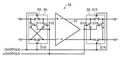
上記適用例に係る物理量検出回路において、前記増幅回路は、前記第1のサンプルホールド回路の出力信号が入力される第1のチョッピング回路と、前記第1のチョッピング回路の出力信号が入力される演算増幅器と、前記演算増幅器の出力信号が入力される第2のチョッピング回路と、を有してもよい。
上記本適用例に係る物理量検出回路において、前記第1のチョッピング回路及び前記第2のチョッピング回路におけるチョッピング周波数は、前記A/D変換回路が前記スイッチトキャパシターフィルター回路の出力信号をサンプリングするサンプリング周波数の1/2以下であってもよい。
上記適用例に係る物理量検出回路は、第1のクロック信号に基づいて、前記物理量検出素子を駆動する駆動信号を生成する駆動回路を含み、前記スイッチトキャパシターフィルター回路は、前記第1のクロック信号を分周して第2のクロック信号を生成する分周回路を有し、前記第1のチョッピング回路及び前記第2のチョッピング回路は、前記第2のクロック信号に基づいて動作してもよい。
上記適用例に係る物理量検出回路において、前記A/D変換回路は、前記スイッチトキャパシターフィルター回路の出力信号を含む複数の信号を時分割にA/D変換してもよい。
が高いので、A/D変換回路において、スイッチトキャパシターフィルター回路の出力信号を含む複数の信号のA/D変換処理を時分割に行うことが可能である。従って、本適用例によれば、回路面積の大幅な増加を抑制しながら、複数の信号を出力可能な物理量検出回路を実現することができる。
上記適用例に係る物理量検出回路において、前記スイッチトキャパシターフィルター回路は、前記物理量検出素子の出力信号に基づく第2の信号をサンプルホールドする第2のサンプルホールド回路と、前記増幅回路の第2の出力信号が入力される第2のスイッチトキャパシター回路と、を有し、前記増幅回路は、前記第1のサンプルホールド回路の出力信号と前記第2のサンプルホールド回路の出力信号とが入力され、前記第1の信号及び前記第2の信号に対して差動で動作してもよい。
本適用例に係る物理量検出装置は、上記のいずれかの物理量検出回路と、前記物理量検出素子と、を備えている。
本適用例に係る電子機器は、上記の物理量検出装置を備えている。
本適用例に係る移動体は、上記の物理量検出装置を備えている。
図1は、本実施形態の物理量検出装置の機能ブロック図である。本実施形態の物理量検出装置1は、3つの物理量検出素子(センサー素子)2(2X,2Y,2Z)と物理量検出回路3を含んで構成されている。
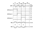
K_Zがいずれもローレベル(電源電圧VSS(例えば0V))のときは、ともに基準電圧VCOM(例えば、VDD/2)の差動信号対PIN,NINを出力する。
間T1〜T4がM/2回繰り返される期間)毎に、クロック信号CHOPCLKがハイレベルかつクロック信号nCHOPCLKがローレベルとなる状態と、クロック信号CHOPCLKがローレベルかつクロック信号nCHOPCLKがハイレベルとなる状態とが繰り返される。
パスフィルターとして機能する。
となる制御信号EN_OUT_X,EN_OUT_Y,EN_OUT_Z,EN_OUT_Tに基づいて、スイッチトキャパシターフィルター回路50Xが出力する差動信号対SOP_X,SON_X、スイッチトキャパシターフィルター回路50Yが出力する差動信号対SOP_Y,SON_Y、スイッチトキャパシターフィルター回路50Zが出力する差動信号対SOP_Z,SON_Z、温度センサー40の出力信号TOのいずれかを選択して(又はいずれも選択しないで)信号対MOP,MONを出力する。具体的には、マルチプレクサー60は、制御信号EN_OUT_Xがハイレベルのときは、差動信号対SOP_X,SON_Xを選択し、差動信号対MOP,MONとして出力する。また、マルチプレクサー60は、制御信号EN_OUT_Yがハイレベルのときは、差動信号対SOP_Y,SON_Yを選択し、差動信号対MOP,MONとして出力する。また、マルチプレクサー60は、制御信号EN_OUT_Zがハイレベルのときは、差動信号対SOP_Z,SON_Zを選択し、差動信号対MOP,MONとして出力する。また、マルチプレクサー60は、制御信号EN_OUT_Tがハイレベルのときは、温度センサー40の出力信号TOを選択し、信号TOと基準電圧VCOMとの信号対を信号対MOP,MONとして出力する。
Kの立ち上がりで、マルチプレクサー60から出力される信号対MOP,MON(スイッチトキャパシターフィルター回路50Yが出力する差動信号対SOP_Y,SON_Y)をサンプリングしてデジタル信号に変換する。また、A/D変換回路70は、制御信号EN_OUT_Zがハイレベルの期間のクロック信号SMPCLKの立ち上がりで、マルチプレクサー60から出力される信号対MOP,MON(スイッチトキャパシターフィルター回路50Zが出力する差動信号対SOP_Z,SON_Z)をサンプリングしてデジタル信号に変換する。また、A/D変換回路70は、制御信号EN_OUT_Tがハイレベルの期間のクロック信号SMPCLKの立ち上がりで、マルチプレクサー60から出力される信号対MOP,MON(温度センサー40の出力信号TOと基準電圧VCOMとの信号対)をサンプリングしてデジタル信号に変換する。
の書き込みや読み出し、デジタルフィルター80から出力されるデジタル信号の読み出し等を行うことができる。インターフェース回路120は、例えば、3端子や4端子のSPI(Serial Peripheral Interface)インターフェース回路であってもよいし、2端子のI2C(Inter-Integrated Circuit)インターフェース回路であってもよい。
演算増幅器57の出力信号に含まれるノイズ成分(演算増幅器57の動作により発生する1/fノイズ)は、チョッピング回路58によってチョッピング周波数fc付近のノイズ成分に変換される。従って、本実施形態の物理量検出装置1(物理量検出回路3)によれば、スイッチトキャパシターフィルター回路50X,50Y,50Zの出力信号に含まれるノイズ成分が低減され、さらなる低ノイズ化が可能である。
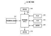
図13は、本実施形態の電子機器の構成の一例を示す機能ブロック図である。図13に示すように、本実施形態の電子機器300は、物理量検出装置310、制御装置(MCU)320、操作部330、ROM(Read Only Memory)340、RAM(Random Access Memory)350、通信部360、表示部370を含んで構成されている。なお、本実施形態の電子機器は、図13の構成要素(各部)の一部を省略又は変更し、あるいは、他の構成要素を付加した構成としてもよい。
図15は、本実施形態の移動体の一例を示す図(上面図)である。図15に示す移動体400は、物理量検出装置410,420,430、コントローラー440,450,460、バッテリー470、ナビゲーション装置480を含んで構成されている。なお、本実施形態の移動体は、図15の構成要素(各部)の一部を省略し、あるいは、他の構成要素を付加した構成としてもよい。
X,50Y,50Zは、入力される差動信号対POP,PONに対して差動で動作しているが、シングルエンド信号が入力され、差動で動作しなくてもよい。
Claims (8)
- 物理量検出素子の出力信号に基づく第1の信号をサンプルホールドする第1のサンプルホールド回路、前記第1のサンプルホールド回路の出力信号が入力される増幅回路、及び前記増幅回路の第1の出力信号が入力される第1のスイッチトキャパシター回路を含み、前記第1のスイッチトキャパシター回路の出力信号が前記増幅回路に入力される、スイッチトキャパシターフィルター回路と、
前記スイッチトキャパシターフィルター回路の出力信号をA/D変換するA/D変換回路と、を含み、
前記増幅回路は、
前記第1のサンプルホールド回路の出力信号が入力される第1のチョッピング回路と、
前記第1のチョッピング回路の出力信号が入力される演算増幅器と、
前記演算増幅器の出力信号が入力される第2のチョッピング回路と、
を含む、物理量検出回路。 - 請求項1において、
前記第1のチョッピング回路及び前記第2のチョッピング回路におけるチョッピング周波数は、前記A/D変換回路が前記スイッチトキャパシターフィルター回路の出力信号をサンプリングするサンプリング周波数の1/2以下である、物理量検出回路。 - 請求項1または2において、
第1のクロック信号に基づいて、前記物理量検出素子を駆動する駆動信号を生成する駆動回路を含み、
前記スイッチトキャパシターフィルター回路は、
前記第1のクロック信号を分周して第2のクロック信号を生成する分周回路を含み、
前記第1のチョッピング回路及び前記第2のチョッピング回路は、前記第2のクロック信号に基づいて動作する、物理量検出回路。 - 請求項1乃至3のいずれか一項において、
前記A/D変換回路は、
前記スイッチトキャパシターフィルター回路の出力信号を含む複数の信号を時分割にA/D変換する、物理量検出回路。 - 請求項1乃至4のいずれか一項において、
前記スイッチトキャパシターフィルター回路は、
前記物理量検出素子の出力信号に基づく第2の信号をサンプルホールドする第2のサンプルホールド回路と、
前記増幅回路の第2の出力信号が入力される第2のスイッチトキャパシター回路と、
を含み、
前記増幅回路は、
前記第1のサンプルホールド回路の出力信号と前記第2のサンプルホールド回路の出力信号とが入力され、
前記第1の信号及び前記第2の信号に対して差動で動作する、物理量検出回路。 - 請求項1乃至5のいずれか一項に記載の物理量検出回路と、
前記物理量検出素子と、
を備えている、物理量検出装置。 - 請求項6に記載の物理量検出装置を備えている、電子機器。
- 請求項6に記載の物理量検出装置を備えている、移動体。
Priority Applications (3)
| Application Number | Priority Date | Filing Date | Title |
|---|---|---|---|
| JP2016140347A JP6733381B2 (ja) | 2016-07-15 | 2016-07-15 | 物理量検出回路、物理量検出装置、電子機器及び移動体 |
| CN201710521602.5A CN107632169A (zh) | 2016-07-15 | 2017-06-30 | 物理量检测电路、物理量检测装置、电子设备和移动体 |
| US15/646,376 US10116275B2 (en) | 2016-07-15 | 2017-07-11 | Physical quantity detection circuit, physical quantity detection device, electronic apparatus, and vehicle |
Applications Claiming Priority (1)
| Application Number | Priority Date | Filing Date | Title |
|---|---|---|---|
| JP2016140347A JP6733381B2 (ja) | 2016-07-15 | 2016-07-15 | 物理量検出回路、物理量検出装置、電子機器及び移動体 |
Publications (3)
| Publication Number | Publication Date |
|---|---|
| JP2018009930A JP2018009930A (ja) | 2018-01-18 |
| JP2018009930A5 JP2018009930A5 (ja) | 2019-07-04 |
| JP6733381B2 true JP6733381B2 (ja) | 2020-07-29 |
Family
ID=60941355
Family Applications (1)
| Application Number | Title | Priority Date | Filing Date |
|---|---|---|---|
| JP2016140347A Active JP6733381B2 (ja) | 2016-07-15 | 2016-07-15 | 物理量検出回路、物理量検出装置、電子機器及び移動体 |
Country Status (3)
| Country | Link |
|---|---|
| US (1) | US10116275B2 (ja) |
| JP (1) | JP6733381B2 (ja) |
| CN (1) | CN107632169A (ja) |
Families Citing this family (7)
| Publication number | Priority date | Publication date | Assignee | Title |
|---|---|---|---|---|
| JP7119478B2 (ja) * | 2018-03-23 | 2022-08-17 | セイコーエプソン株式会社 | 回路装置、物理量測定装置、電子機器及び移動体 |
| JP7234655B2 (ja) * | 2019-01-29 | 2023-03-08 | セイコーエプソン株式会社 | 物理量検出回路、物理量センサー、電子機器、移動体及び物理量検出回路の動作方法 |
| US11211101B2 (en) * | 2019-12-03 | 2021-12-28 | Micron Technology, Inc. | Differential amplifier schemes for sensing memory cells |
| JP7322718B2 (ja) * | 2020-01-17 | 2023-08-08 | セイコーエプソン株式会社 | 物理量検出回路、物理量センサー、電子機器、移動体及び物理量検出回路の動作方法 |
| JP7456284B2 (ja) * | 2020-05-25 | 2024-03-27 | セイコーエプソン株式会社 | 物理量検出回路、物理量検出装置、電子機器及び移動体 |
| JP2021185356A (ja) * | 2020-05-25 | 2021-12-09 | セイコーエプソン株式会社 | 物理量検出回路、物理量検出装置、電子機器及び移動体 |
| TWI806420B (zh) * | 2022-02-11 | 2023-06-21 | 瑞鼎科技股份有限公司 | 電容變化量測電路 |
Family Cites Families (12)
| Publication number | Priority date | Publication date | Assignee | Title |
|---|---|---|---|---|
| EP1793497B1 (en) | 2005-12-02 | 2011-04-27 | STMicroelectronics Srl | Device and method for reading a capacitive sensor, in particular of a micro-electromechanical type |
| JP2007214613A (ja) * | 2006-02-07 | 2007-08-23 | Seiko Instruments Inc | 増幅回路 |
| CN101568805B (zh) | 2006-09-28 | 2011-05-04 | 麦德托尼克公司 | 低功率传感器系统的电容接口电路 |
| JP4821900B2 (ja) * | 2009-09-11 | 2011-11-24 | セイコーエプソン株式会社 | 検出装置、物理量測定装置及び電子機器 |
| JP2011069628A (ja) * | 2009-09-24 | 2011-04-07 | Seiko Epson Corp | 物理量測定装置及び電子機器 |
| JP2012049599A (ja) * | 2010-08-24 | 2012-03-08 | Seiko Epson Corp | スイッチドキャパシター回路、検出装置及び電子機器 |
| JP5825624B2 (ja) * | 2011-07-08 | 2015-12-02 | セイコーエプソン株式会社 | スイッチトキャパシター積分回路、フィルター回路、物理量測定装置、及び電子機器 |
| JP6201774B2 (ja) | 2014-01-16 | 2017-09-27 | セイコーエプソン株式会社 | 物理量検出回路、物理量検出装置、電子機器および移動体 |
| US9411987B2 (en) * | 2014-08-18 | 2016-08-09 | Qualcomm Incorporated | Low noise and low power passive sampling network for a switched-capacitor ADC with a slow reference generator |
| JP5850121B2 (ja) * | 2014-10-07 | 2016-02-03 | セイコーエプソン株式会社 | 物理量測定装置及び電子機器 |
| US9214949B1 (en) * | 2014-12-08 | 2015-12-15 | Broadcom Corporation | Analog to digital converter having switched capacitor power supply |
| US9413377B1 (en) * | 2015-12-15 | 2016-08-09 | Lncku Research And Development Foundation | Switched capacitor circuit and compensation method thereof, and analog to digital converter |
-
2016
- 2016-07-15 JP JP2016140347A patent/JP6733381B2/ja active Active
-
2017
- 2017-06-30 CN CN201710521602.5A patent/CN107632169A/zh not_active Withdrawn
- 2017-07-11 US US15/646,376 patent/US10116275B2/en active Active
Also Published As
| Publication number | Publication date |
|---|---|
| JP2018009930A (ja) | 2018-01-18 |
| US20180019717A1 (en) | 2018-01-18 |
| CN107632169A (zh) | 2018-01-26 |
| US10116275B2 (en) | 2018-10-30 |
Similar Documents
| Publication | Publication Date | Title |
|---|---|---|
| JP6733381B2 (ja) | 物理量検出回路、物理量検出装置、電子機器及び移動体 | |
| JP6834581B2 (ja) | 物理量センサー、電子機器及び移動体 | |
| JP6911449B2 (ja) | 物理量検出回路、物理量センサー、電子機器及び移動体 | |
| US10291215B2 (en) | Data processing circuit, physical quantity detection circuit, physical quantity detection device, electronic apparatus, and moving object | |
| JP7151061B2 (ja) | 故障判定回路、物理量検出装置、電子機器、移動体及び故障判定方法 | |
| US11650056B2 (en) | Physical quantity detection circuit, physical quantity sensor, electronic apparatus, vehicle, and operation method of physical quantity detection circuit | |
| JP2021185356A (ja) | 物理量検出回路、物理量検出装置、電子機器及び移動体 | |
| JP2018165641A (ja) | 故障判定回路、物理量検出装置、電子機器及び移動体 | |
| JP6808997B2 (ja) | 信号処理回路、物理量検出装置、姿勢演算装置、電子機器及び移動体 | |
| JP7447571B2 (ja) | 物理量検出回路、物理量センサー、電子機器、移動体および物理量検出回路の動作方法 | |
| CN112147371B (zh) | 物理量检测电路、物理量传感器及其故障诊断方法 | |
| JP2024024629A (ja) | 故障診断回路、電子回路、物理量検出回路、物理量センサー、電子機器、及び移動体 | |
| JP2023105141A (ja) | 物理量検出回路、物理量センサー、電子機器、及び移動体物理量センサー | |
| JP7456284B2 (ja) | 物理量検出回路、物理量検出装置、電子機器及び移動体 | |
| US11333526B2 (en) | Physical quantity detection circuit, physical quantity sensor, electronic device, vehicle, and failure diagnosis method of physical quantity sensor | |
| JP7322718B2 (ja) | 物理量検出回路、物理量センサー、電子機器、移動体及び物理量検出回路の動作方法 | |
| JP7323015B2 (ja) | 物理量処理回路、物理量検出装置、電子機器、及び移動体 | |
| JP2018009916A (ja) | 整流回路、駆動回路、物理量検出装置、電子機器及び移動体 |
Legal Events
| Date | Code | Title | Description |
|---|---|---|---|
| A521 | Written amendment |
Free format text: JAPANESE INTERMEDIATE CODE: A523 Effective date: 20190528 |
|
| A621 | Written request for application examination |
Free format text: JAPANESE INTERMEDIATE CODE: A621 Effective date: 20190528 |
|
| A977 | Report on retrieval |
Free format text: JAPANESE INTERMEDIATE CODE: A971007 Effective date: 20200325 |
|
| A131 | Notification of reasons for refusal |
Free format text: JAPANESE INTERMEDIATE CODE: A131 Effective date: 20200331 |
|
| A521 | Written amendment |
Free format text: JAPANESE INTERMEDIATE CODE: A523 Effective date: 20200525 |
|
| TRDD | Decision of grant or rejection written | ||
| A01 | Written decision to grant a patent or to grant a registration (utility model) |
Free format text: JAPANESE INTERMEDIATE CODE: A01 Effective date: 20200609 |
|
| A61 | First payment of annual fees (during grant procedure) |
Free format text: JAPANESE INTERMEDIATE CODE: A61 Effective date: 20200622 |
|
| R150 | Certificate of patent or registration of utility model |
Ref document number: 6733381 Country of ref document: JP Free format text: JAPANESE INTERMEDIATE CODE: R150 |


