JP6698103B2 - Steering method - Google Patents
Steering method Download PDFInfo
- Publication number
- JP6698103B2 JP6698103B2 JP2017554708A JP2017554708A JP6698103B2 JP 6698103 B2 JP6698103 B2 JP 6698103B2 JP 2017554708 A JP2017554708 A JP 2017554708A JP 2017554708 A JP2017554708 A JP 2017554708A JP 6698103 B2 JP6698103 B2 JP 6698103B2
- Authority
- JP
- Japan
- Prior art keywords
- rudder
- propeller
- shaft
- steering
- steered
- Prior art date
- Legal status (The legal status is an assumption and is not a legal conclusion. Google has not performed a legal analysis and makes no representation as to the accuracy of the status listed.)
- Active
Links
Images


Classifications
-
- B—PERFORMING OPERATIONS; TRANSPORTING
- B63—SHIPS OR OTHER WATERBORNE VESSELS; RELATED EQUIPMENT
- B63H—MARINE PROPULSION OR STEERING
- B63H25/00—Steering; Slowing-down otherwise than by use of propulsive elements; Dynamic anchoring, i.e. positioning vessels by means of main or auxiliary propulsive elements
- B63H25/06—Steering by rudders
- B63H25/38—Rudders
- B63H2025/388—Rudders with varying angle of attack over the height of the rudder blade, e.g. twisted rudders
Landscapes
- Chemical & Material Sciences (AREA)
- Engineering & Computer Science (AREA)
- Combustion & Propulsion (AREA)
- Mechanical Engineering (AREA)
- Ocean & Marine Engineering (AREA)
- Other Liquid Machine Or Engine Such As Wave Power Use (AREA)
- Organic Low-Molecular-Weight Compounds And Preparation Thereof (AREA)
- Thin Film Transistor (AREA)
- Wind Motors (AREA)
Description
本発明は、プロペラ回転流を効果的に回収する船舶用舵、操舵方法及び船舶に関する。 The present invention relates to a marine vessel rudder, a steering method and a marine vessel that effectively collects a propeller rotating flow.
船舶用舵は、船尾配置を容易にし、船尾肥大度を減少させるために、舵のコード長を短くすることが要望される。
この要望を満たし、かつ操縦性能を維持する手段として、例えば特許文献1,2が提案されている。The rudder for a ship is required to have a short rudder cord length in order to facilitate stern placement and reduce the degree of stern enlargement.
As means for satisfying this demand and maintaining steering performance, for example,
特許文献1の「大型船用二枚舵システム」では、一基の推進プロペラの後方に一対の高揚力舵を配設する。各高揚力舵は、舵ブレードの頂端部と底端部にそれぞれ頂端板と底端板を有する。また、このシステムでは、各舵ブレードの内舷側の面上で推進プロペラの軸心とほぼ同じ水準位置にほぼ前縁部から後方に向けて所定の翼弦長を有するフィンを設ける。さらに、このシステムでは、各舵ブレードの弦長を推進プロペラ直径の60〜45%に構成する。
In the "two-rudder system for large ships" of
特許文献2の「船舶用舵」では、舵本体の水平断面形状が、前縁部形状が円弧状またはこれに類似する形状からなり、舵本体の後方に向かって徐々に断面幅が増加して最大幅に達し、外側に凸の形状から外側に凹の形状に変化しながら断面幅が減少していく。その後、水平断面形状は、後端まで、ほぼ平行な直線で形成される直線状部分を有し、有限幅をもつ後端を有する。
In the "vessel rudder" of
特許文献1は、一軸二舵システムとして知られている。一軸二舵システムでは二枚の舵をプロペラ後方に左右対称に配置する。一軸二舵システムは多種多様な操船モードを有し、操船性に優れているが、プロペラセンターを外して舵を配置するため、プロペラ回転流のエネルギー回収率が悪化する。そのため、一軸二舵システムではプロペラ回転流のエネルギー回収率の悪化を補填するためのフィンの追加、あるいは舵のコード長を短くした分、船体を延長させて船尾肥大度の減少をはかるのが一般的である。
一方で特許文献2のように、舵自体を高揚力化させる高揚力舵に関する技術も研究されてきた。高揚力舵は、小舵面積かつ高アスペクト比化が可能であり、舵のコード長を短くできる。最新の船舶の舵は概ね高揚力化がはかられており、舵コード長は極限まで短くなっている。従って、更なる性能向上のために既存の一軸二舵システムを適用しても、ベースになる一舵のコード長が既に短くなっており、その効果が得にくいという問題がある。
On the other hand, as in
本発明は、最新船舶の舵性能を更に向上させるために、創案されたものである。すなわち、本発明の目的は、プロペラ回転流のエネルギーを効果的に利用でき、かつ舵の面積および翼厚を更に減少させることができる船舶用舵、操舵方法及び船舶を提供することにある。 The present invention was devised in order to further improve the rudder performance of the latest ships. That is, an object of the present invention is to provide a marine vessel rudder, a steering method, and a marine vessel that can effectively use the energy of a propeller rotating flow and further reduce the rudder area and blade thickness.
本発明によれば、船尾に配置されたプロペラの後方かつ軸線上に上下に配置された上部舵及び下部舵を備え、
前記上部舵と前記下部舵は、前記プロペラの前記軸線上から、左舷側及び右舷側にそれぞれ独立に転舵可能であり、減速時又は減速旋回時に、前記上部舵及び前記下部舵の一方を左舷側に転舵し、他方を右舷側に転舵する、船舶用舵が提供される。
According to the present invention, the upper rudder and the lower rudder are arranged rearward of the propeller arranged at the stern and vertically on the axis,
The lower rudder and the upper rudder, from the axis of the propeller, Ri each independently allowing turning der on the port side and the starboard side, during deceleration or decelerating turning, one of the upper rudder and the lower rudder A ship rudder that steers to the port side and steers the other to the starboard side is provided.
前記上部舵と前記下部舵をそれぞれ独立に転舵可能な上部用舵取機と下部用舵取機を備える。 The upper rudder and the lower rudder are capable of independently turning the upper rudder and the lower rudder.
前記下部舵の肉厚分布は、前記上部舵より薄く構成されている。 The thickness distribution of the lower rudder is smaller than that of the upper rudder.
プロペラ回転方向を後方から見て、時計回りとした場合、
前記上部舵は、左舷側から右舷側に流れるプロペラ回転流に適した翼形を有し、
前記下部舵は、右舷側から左舷側に流れるプロペラ回転流に適した翼形を有する。When looking at the propeller rotation direction from the rear,
The upper rudder has an airfoil suitable for a propeller rotating flow from the port side to the starboard side,
The lower rudder has an airfoil suitable for a propeller rotating flow that flows from the starboard side to the port side.
前記上部舵と前記下部舵とは、翼形又は翼形の反り線が相違する。 The upper rudder and the lower rudder differ in airfoil or airfoil warp line.
また、本発明によれば、船尾に配置されたプロペラの後方かつ軸線上に上下に配置された上部舵及び下部舵を準備し、
前記上部舵及び前記下部舵を、前記プロペラの前記軸線上から、左舷側及び右舷側にそれぞれ独立に転舵し、
減速時又は減速旋回時に、前記上部舵及び前記下部舵の一方を左舷側に転舵し、他方を右舷側に転舵する、操舵方法が提供される。
Further, according to the present invention, an upper rudder and a lower rudder arranged rearward of the propeller arranged at the stern and vertically on the axis are prepared,
The upper rudder and the lower rudder are independently steered from the axis of the propeller to the port side and the starboard side, respectively .
A steering method is provided in which one of the upper rudder and the lower rudder is steered to the port side and the other is steered to the starboard side during deceleration or deceleration turning .
さらに、本発明によれば、上述した船舶用舵を装備した、船舶が提供される。 Further, according to the present invention, there is provided a ship equipped with the above-mentioned ship rudder.
本発明によれば、プロペラセンター(プロペラの後方かつ軸線上)に上部舵及び下部舵を配置するので、プロペラ回転流のエネルギーを上部舵及び下部舵により効果的に回収できる。 According to the present invention, since the upper rudder and the lower rudder are arranged at the propeller center (rearward of the propeller and on the axis), the energy of the propeller rotating flow can be effectively recovered by the upper rudder and the lower rudder.
特に、本発明の船舶用舵は、直進時及び旋回時に、上部舵と下部舵を独立に転舵させてそれぞれ適切な舵角を取ることで、いかなるプロペラ回転数においても常にプロペラ回転流のエネルギー回収に最適な舵角を実現できる。また、その結果、本発明の船舶用舵は、上部舵と下部舵が一体となった1枚の舵と比較して、高揚力を発生させることが可能となり、トータルの舵面積を低減することができる。 In particular, the marine vessel rudder of the present invention, at the time of going straight and turning, by independently steering the upper rudder and the lower rudder to take appropriate steering angles, the energy of the propeller rotating flow is always maintained at any propeller rotational speed. The optimum rudder angle for collection can be realized. Further, as a result, the marine vessel rudder of the present invention can generate a high lift force as compared with a single rudder in which the upper rudder and the lower rudder are integrated, and reduce the total rudder area. You can
また、上部舵と下部舵が一体となった1枚の舵と比較して、上部舵と下部舵の舵面積がほぼ半減するので、上部舵と下部舵の設計荷重が減少する。従って、翼厚が減少して舵単体性能を向上させることができる。 Further, since the rudder area of the upper rudder and the lower rudder is almost halved compared with one rudder in which the upper rudder and the lower rudder are integrated, the design load of the upper rudder and the lower rudder is reduced. Therefore, the blade thickness can be reduced and the rudder unit performance can be improved.
従って、本発明によれば、プロペラ回転流のエネルギーを効果的に利用でき、かつ舵の面積および翼厚を減少させることができる。
Therefore, according to the present invention, the energy of the propeller rotating flow can be effectively used, and the rudder area and blade thickness can be reduced.
本発明の実施形態を図面に基づいて説明する。なお、各図において共通する部分には同一の符号を付し、重複した説明を省略する。 An embodiment of the present invention will be described with reference to the drawings. In addition, in each figure, the common part is denoted by the same reference numeral, and the duplicated description will be omitted.
図1は、本発明の船舶用舵100の実施形態を示す側面図であり、図2は図1のA−A線による断面図である。
図1、図2において、1は船舶、2は船尾、3はベースライン、4はプロペラセンター、5は転舵軸、6は右舷側、7は左舷側である。FIG. 1 is a side view showing an embodiment of a
In FIGS. 1 and 2, 1 is a ship, 2 is a stern, 3 is a baseline, 4 is a propeller center, 5 is a steering shaft, 6 is a starboard side, and 7 is a port side.
この例において、ベースライン3は、船舶1の下面に相当する水平線である。また、プロペラセンター4は、プロペラ8の軸線を意味する。プロペラセンター4は、水平でも傾斜していてもよい。
転舵軸5は、この例では鉛直軸であり、プロペラセンター4と交差する。なお、転舵軸5は、プロペラセンター4と交差する限りで、鉛直でなくてもよい。
プロペラ8は、この例では単一であるが、2つのプロペラ8が互いに逆回転する二重反転プロペラであってもよい。In this example, the baseline 3 is a horizontal line corresponding to the lower surface of the
The steered
The
図1、図2において、本発明の船舶用舵100は、上部舵10A及び下部舵10Bと、上部用操舵機20A及び下部用操舵機20Bと、を備える。
1 and 2, a
上部舵10A及び下部舵10Bは、船尾2に配置されたプロペラ8の後方かつ軸線上に上下に配置されている。「プロペラ8の後方かつ軸線上」とは、上部舵10A及び下部舵10Bの共通の転舵軸5が、プロペラ8の後方のプロペラセンター4を含む鉛直平面上に位置することを意味する。
The
図1において、上部舵10Aと下部舵10Bは、コード長Lと舵高さHがほぼ等しく構成されている。またこの例において、上部舵10Aと下部舵10Bの境界面は、プロペラセンター4の高さとほぼ一致している。
また、下部舵10Bの下端は、ベースライン3よりも上方であることが好ましい。In FIG. 1, the
Also, the lower end of the
なお、本発明はこの例に限定されない。すなわち、上部舵10Aと下部舵10Bとは、コード長L又は舵高さHが相違してもよい。また、上部舵10Aと下部舵10Bの境界面が、プロペラセンター4と相違してもよい。
The present invention is not limited to this example. That is, the
図1、図2において、上部舵10Aと下部舵10Bは、共通(同一)の転舵軸5を有する。
上部用操舵機20Aと下部用操舵機20Bは、上部舵10Aと下部舵10Bをそれぞれ独立に転舵する機能を有する。
すなわち、上部舵10A及び下部舵10Bは、プロペラ8の軸線上から、左舷側7及び右舷側6にそれぞれ転舵可能である。上部舵10A及び下部舵10Bの転舵角度は、プロペラセンター4に対して左舷側7及び右舷側6に最大90度以上であるのがよい。1 and 2, the
The
That is, the
上述した構成により、プロペラセンター4(プロペラ8の後方かつ軸線上)に上部舵10A及び下部舵10Bを配置するので、プロペラ回転流9a,9bのエネルギーを上部舵10A及び下部舵10Bにより効果的に回収することができる。
With the configuration described above, the
特に、本発明の船舶用舵100は、直進時及び旋回時に、上部舵10Aと下部舵10Bを独立に転舵させてそれぞれ適切な舵角を取ることで、いかなるプロペラ回転数においても常にプロペラ回転流9a,9bのエネルギー回収に最適な舵角を実現できる。また、その結果、本発明の船舶用舵100は、上部舵10Aと下部舵10Bが一体となった1枚の舵と比較して、高揚力を発生させることが可能となり、トータルの舵面積を低減することができる。
In particular, the
また、上部舵10Aと下部舵10Bが一体となった1枚の舵と比較して、上部舵10Aと下部舵10Bの舵面積がほぼ半減する。従って、翼厚が減少して舵単体性能を向上させることができる。
Further, the rudder area of the
図1、図2において、上部用操舵機20Aは、上部用舵軸22aと上部用舵取装置24aとを有する。上部用舵軸22aは、中空円筒形の軸であり、下端が上部舵10Aに固定され、転舵軸5に沿って上方に延びる。上部用舵取装置24aは、転舵軸5を中心に上部用舵軸22aの上端部を転舵する。この転舵角度は、左舷側7及び右舷側6に最大90度以上であるのがよい。
1 and 2, the
また、下部用操舵機20Bは、下部用舵軸22bと下部用舵取装置24bとを有する。下部用舵軸22bは、この例では中実軸であり、下端が下部舵10Bに固定され、転舵軸5に沿って上方に延びる。下部用舵取装置24bは、転舵軸5を中心に下部用舵軸22bの上端部を転舵する。この転舵角度は、左舷側7及び右舷側6に最大90度以上であるのがよい。
The
上述した構成により、上部舵10Aと下部舵10Bが一体となった1枚の舵と比較して、上部舵10Aと下部舵10Bの舵面積がほぼ半減し、上部舵10Aと下部舵10Bの設計荷重が減少するので、上部用舵軸22a及び下部用舵軸22bの必要最大トルクがほぼ半減し、それぞれの必要寸法(例えば直径)を小さく(細く)することができる。
With the configuration described above, the rudder area of the
転舵軸5は、上部舵10A及び下部舵10Bのコード長Lの中心近傍、又は最大肉厚部近傍に位置することが好ましい。また下部舵10Bの肉厚は、下部用舵軸22bの接続部において、下部用舵軸22bの直径より大きい必要がある。
The steered
上述したように、上部舵10Aと下部舵10Bが一体となった1枚の舵と比較して、舵面積がほぼ半減し、設計荷重が減少するので、下部用舵軸22bの直径を従来より小さく(細く)することができ、下部舵10Bの肉厚分布を従来より薄くすることができる。なおこの場合でも、プロペラ回転流9bのエネルギー回収に最適な舵角に下部舵10Bを独立に転舵させることができるので、プロペラ回転流9bのエネルギー回収率を高めることができる。
As described above, since the rudder area is almost halved and the design load is reduced as compared with one rudder in which the
一方、上部舵10Aは、貫通孔11(後述する)を設ける必要があるため、下部舵10Bの肉厚より大きくなる。しかし、上部舵10Aと下部舵10Bが一体となった1枚の舵と比較して、舵面積がほぼ半減し、設計荷重が減少するので、上部用舵軸22aの直径も従来より小さく(細く)することができる。またこの場合も、プロペラ回転流9aのエネルギー回収に最適な舵角に上部舵10Aを独立に転舵させることができるので、プロペラ回転流9aのエネルギー回収率を高めることができる。
On the other hand, the
図1、図2において、中空円筒形の上部用舵軸22aと中実の下部用舵軸22bとは、転舵軸5を同軸とする二重管である。
In FIGS. 1 and 2, the hollow cylindrical
上部用舵軸22aは、船尾2に設けられたハウジング26の内側に、第1軸受27aを介して、転舵軸5を中心に回転自在に取り付けられている。また、図示しないシールにより、上部用舵軸22aとハウジング26の隙間から海水Wが流入しないように密封されている。
上部舵10Aは、その上面から下面まで転舵軸5に沿って貫通する貫通孔11を有する。The
The
下部用舵軸22bは、貫通孔11と上部用舵軸22aの内側に、第2軸受27bを介して転舵軸5を中心に回転自在に取り付けられている。また、図示しないシールにより、貫通孔11及び下部用舵軸22bと上部用舵軸22aの隙間から海水Wが流入しないように密封されている。
The
上部用舵取装置24aは、上部用舵軸22aの上端部に固定され水平に延びる上部用チラー28aと、転舵軸5を中心に上部用チラー28aを水平に揺動する複数の油圧シリンダ29aとを有する。
下部用舵取装置24bは、下部用舵軸22bの上端部に固定され水平に延びる下部用チラー28bと、転舵軸5を中心に下部用チラー28bを水平に揺動する複数の油圧シリンダ29bとを有する。
油圧シリンダ29a,29bは、それぞれ図示しない油圧ユニットにより独立に制御され、上部舵10Aと下部舵10Bをそれぞれ独立に転舵するようになっている。The
The
The
上述したように、上部舵10Aと下部舵10Bが一体となった1枚の舵と比較して、上部舵10Aと下部舵10Bの舵面積がほぼ半減し、上部舵10Aと下部舵10Bの設計荷重が減少するので、上部用舵取装置24a及び下部用舵取装置24bの必要最大トルクがほぼ半減する。従って、上部用舵取装置24a及び下部用舵取装置24bの構成機器を小型化することができる。
As described above, compared with one rudder in which the
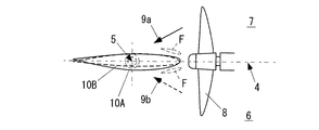
図3Aは、図1の模式的平面図である。この図において、上部舵10Aを実線、下部舵10Bを破線で示している。
FIG. 3A is a schematic plan view of FIG. 1. In this figure, the
この図において、下部舵10Bの肉厚分布は、上部舵10Aより薄く構成されている。
また、プロペラ回転方向を後方から見て、時計回りとした場合、上部舵10Aは、左舷側7から右舷側6に流れるプロペラ回転流9a(実線の矢印で示す)に適した翼形を有する。
また、プロペラ回転方向を後方から見て、時計回りとした場合、下部舵10Bは、右舷側6から左舷側7に流れるプロペラ回転流9b(破線の矢印で示す)に適した翼形を有する。In this figure, the thickness distribution of the
Further, when the propeller rotating direction is viewed clockwise from the rear, the
Further, when the propeller rotation direction is viewed clockwise from the rear, the
図3Bは、直進時に上部舵10Aに発生する流体力の説明図である。
上部舵10Aに対し左舷側7から右舷側6に流れる回転流9aにより、流れと直角方向に揚力La、平行方向に抗力Daが発生する。抗力Daに対して揚力Laが大きくなるように、上部舵10Aの舵角および翼形を選択すれば、前進方向の分力を効率的に得ることができる。FIG. 3B is an explanatory diagram of a fluid force generated in the
Due to the
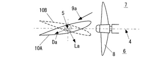
図3Cは、直進時に下部舵10Bに発生する流体力の説明図である。
下部舵10Bに対し右舷側6から左舷側7に流れる回転流9bにより、流れと直角方向に揚力Lb、平行方向に抗力Dbが発生する。抗力Dbに対して揚力Lbが大きくなるように、下部舵10Aの舵角および翼形を選択すれば、前進方向の分力を効率的に得ることができる。FIG. 3C is an explanatory diagram of a fluid force generated in the
Due to the
すなわち、この例において、上部舵10Aと下部舵10Bとは、翼形又は翼形の反り線が相違する。
That is, in this example, the
上述した構成により、本発明の船舶用舵100は、直進時において上部舵10Aと下部舵10Bが一体となった1枚の舵と比較して、プロペラ回転流9a,9bのエネルギーを効率的に回収し、舵に発生する流体力の前進方向の分力を効率的に得ることができる。
なお、上部舵10Aと下部舵10Bは、この例に限定されず、それぞれプロペラ回転流9a,9bに適した翼形である限りで、高揚力化のため、フィンF(図3Aに破線で示す)又はフラップ(図示せず)を有してもよい。With the above-described configuration, the
The
また、本発明の上部舵10Aと下部舵10Bは、上述した構成に限定されない。すなわち、上部舵10A及び下部舵10Bの翼形は、プロペラセンター4に対し右舷側6と左舷側7が対称であってもよい。
Further, the
本発明の船舶1は、上述した船舶用舵100を装備する。
上述した船舶用舵100を装備することにより、舵のコード長Lを短くすることができ、船尾配置を容易にし、船尾肥大度を減少させることができる。
なお、本発明の船舶1は、1軸のプロペラ8に限定されず、2軸又は3軸以上のプロペラ8を有してもよい。その場合、上述した上部舵10A及び下部舵10Bと上部用操舵機20A及び下部用操舵機20Bは、複数のプロペラ8の各軸にそれぞれ設けることが好ましい。なお、本発明の船舶1は、複数のプロペラ8のうち、一部のみに、上述した上部舵10A及び下部舵10Bと上部用操舵機20A及び下部用操舵機20Bを設けてもよい。The
By equipping the above-mentioned
The
本発明の船舶用舵100の操舵方法は、上述した上部舵10A及び下部舵10Bと上部用操舵機20A及び下部用操舵機20Bとを準備し、上部舵10A及び下部舵10Bをそれぞれ独立に転舵する。
The steering method of the
図4A,図4B,図4Cは、本発明の操舵方法の説明図である。
以下、上部舵10A及び下部舵10Bが右舷側6と左舷側7とで対称とし、下部舵10Bの肉厚分布は、上部舵10Aより薄く構成されている場合を説明する。なお、ここでは舵に働く流体力を前後方向成分Fと左右方向成分Sに分けて説明する。上部舵10Aに働く流体力のうち、前後方向成分をFa、左右方向成分をSa、下部舵10Bに働く流体力うち、前後方向成分をFb、左右方向成分をSbとする。4A, 4B, and 4C are explanatory views of the steering method of the present invention.
Hereinafter, the case where the
図4Aは、直進時の上部舵10A及び下部舵10Bの位置を示す図であり、図4Bは左旋回時の上部舵10A及び下部舵10Bの位置を示す図である。
FIG. 4A is a diagram showing the positions of the
図4Aに示すように、直進時の上部舵10A及び下部舵10Bの位置は、平面視で実質的に一致し、上部舵10Aと下部舵10Bが一体となった1枚の舵と同様に、プロペラ回転流9a,9bのエネルギーを効果的に回収することができる。
As shown in FIG. 4A, the positions of the
また、図4Bに示すように、左旋回時の上部舵10A及び下部舵10Bの位置も、平面視で実質的に一致させることができ、上部舵10Aと下部舵10Bが一体となった1枚の舵と同様であるが、上部舵10Aは左旋回に寄与する力を出すのに対し、下部舵10Bは左旋回への寄与が小さい。これではプロペラ回転流9a,9bのエネルギーを効果的に利用できていない。右旋回時も同様の問題がある。
Further, as shown in FIG. 4B, the positions of the
図4Cは、左旋回時の上部舵10A及び下部舵10Bの位置を示す別の図である。
上述したように、上部舵10Aには左舷側7から右舷側6に流れるプロペラ回転流9aが作用し、下部舵10Bには右舷側6から左舷側7に流れるプロペラ回転流9bが作用する。
従って、この図に示すように、本発明の操舵方法は、左旋回時においても、上部舵10Aと下部舵10Bを独立に転舵させてそれぞれ適切な舵角を取ることで、プロペラ回転数に応じてプロペラ回転流9a,9bのエネルギーを有効に利用し、高揚力を発揮させることが可能である。右旋回時及び直進時も同様である。FIG. 4C is another diagram showing the positions of the
As described above, the
Therefore, as shown in this figure, the steering method of the present invention, even at the time of turning left, turns the
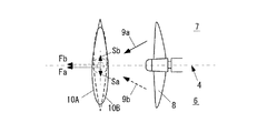
図5Aと図5Bは、減速時の本発明の操舵方法の説明図である。
この図に示すように、本発明の操舵方法では、減速時に、上部舵10A及び下部舵10Bの一方を左舷側7に転舵し、他方を右舷側6に転舵する。5A and 5B are explanatory views of the steering method of the present invention during deceleration.
As shown in this figure, in the steering method of the present invention, one of the
図5Aは、90度の減速モード、すなわち上部舵10Aを約90度左舷側7に転舵し、下部舵10Bを約90度右舷側6に転舵した状態を示す図である。この場合、流れに対して舵がほぼ直角に近い状態で配置されるため、揚力は得られず、抗力が顕著になる。その結果、舵には前進方向とは反対向きに大きな流体力が発生し、船舶1を急減速することができる。
FIG. 5A is a diagram showing a deceleration mode of 90 degrees, that is, a state in which the
図5Bは、30度の減速モード、すなわち上部舵10Aを約30度左舷側7に転舵し、下部舵10Bを約30度右舷側6に転舵した状態を示す図である。
90度以下の舵角、例えば図5Bの30度の減速モードの場合も、90度の舵角(図5A)と比較して、減速効果は落ちるが、類似の効果が得られる。FIG. 5B is a diagram showing a deceleration mode of 30 degrees, that is, a state in which the
In the case of a steering angle of 90 degrees or less, for example, in the deceleration mode of 30 degrees of FIG. 5B, the deceleration effect is lower than that of the steering angle of 90 degrees (FIG. 5A), but a similar effect is obtained.
なお、上部舵10A及び下部舵10Bの最大操舵角は、右舷側6及び左舷側7に90度以上であってもよい。
この構成により、船舶1の後進時においても、船舶1の操舵性を確保することができる。The maximum steering angle of the
With this configuration, the steerability of the
図6A,図6Bは、減速旋回時の本発明の操舵方法の説明図である。 6A and 6B are explanatory views of the steering method of the present invention at the time of deceleration turning.
図6Aは、減速右旋回モード、すなわち上部舵10Aを約90度左舷側7に転舵し、下部舵10Bを約30度右舷側6に転舵した状態を示す図である。この場合、上部舵10Aが主に減速の役割を、下部舵10Bが主に右旋回の役割を担うため、船舶1を減速しながら、右旋回させることができる。
FIG. 6A is a diagram showing a decelerating right turn mode, that is, a state in which the
図6Bは、減速左旋回モード、すなわち上部舵10Aを約30度左舷側7に転舵し、下部舵10Bを約90度右舷側6に転舵した状態を示す図である。この場合、上部舵10Aが主に左旋回の役割を、下部舵10Bが主に減速の役割を担うため、船舶1を減速しながら、左旋回させることができる。
FIG. 6B is a diagram showing a decelerating left turn mode, that is, a state in which the
なお、上述した本発明の操舵方法は、上部舵10A及び下部舵10Bの翼形の反り線及び翼形が相違する場合にも、同様に適用することができる。
The steering method of the present invention described above can be similarly applied to the case where the
上述した本発明によれば、プロペラセンター4(プロペラ8の後方かつ軸線上)に上部舵10A及び下部舵10Bを配置するので、プロペラ回転流9a,9bのエネルギーを上部舵10A及び下部舵10Bにより効果的に回収できる。
According to the present invention described above, since the
特に、本発明の船舶用舵100は、直進時及び旋回時に、上部舵10Aと下部舵10Bを独立に転舵させてそれぞれ適切な舵角を取ることで、いかなるプロペラ回転数においても常にプロペラ回転流9a,9bのエネルギー回収に最適な舵角を実現できる。また、その結果、本発明の船舶用舵100は、上部舵10Aと下部舵10Bが一体となった1枚の舵と比較して、高揚力を発生させることが可能となり、トータルの舵面積を低減することができる。
In particular, the
また、上部舵10Aと下部舵10Bが一体となった1枚の舵と比較して、上部舵10Aと下部舵10Bの舵面積がほぼ半減するので、上部舵10Aと下部舵10Bの設計荷重が減少する。従って、翼厚が減少して舵単体性能を向上させることができる。
Further, compared with one rudder in which the
従って、本発明によれば、プロペラ回転流9a,9bのエネルギーを効果的に利用でき、かつ舵の面積および翼厚を減少させることができる。
Therefore, according to the present invention, the energy of the
本発明は上述した実施の形態に限定されず、本発明の要旨を逸脱しない範囲で種々変更を加え得ることは勿論である。 The present invention is not limited to the embodiments described above, and it goes without saying that various modifications can be made without departing from the gist of the present invention.
F フィン
H 舵高さ
L コード長
W 海水
1 船舶
2 船尾
3 ベースライン
4 プロペラセンター
5 転舵軸
6 右舷側
7 左舷側
8 プロペラ
9a,9b プロペラ回転流
10A 上部舵
10B 下部舵
11 貫通孔
20A 上部用操舵機
20B 下部用操舵機
22a 上部用舵軸
22b 下部用舵軸
24a 上部用舵取装置
24b 下部用舵取装置
26 ハウジング
27a 第1軸受
27b 第2軸受
28a 上部用チラー
28b 下部用チラー
29a,29b 油圧シリンダ
100 船舶用舵F Fin H Rudder height L Code
Claims (1)
前記上部舵及び前記下部舵を、前記プロペラの前記軸線上から、左舷側及び右舷側にそれぞれ独立に転舵し、
減速時又は減速旋回時に、前記上部舵及び前記下部舵の一方を左舷側に転舵し、他方を右舷側に転舵する、操舵方法。
Prepare the upper rudder and the lower rudder arranged vertically behind the propeller arranged on the stern and on the axis,
The upper rudder and the lower rudder are independently steered from the axis of the propeller to the port side and the starboard side, respectively.
A steering method in which one of the upper rudder and the lower rudder is steered to the port side and the other is steered to the starboard side during deceleration or turning during deceleration.
Applications Claiming Priority (1)
| Application Number | Priority Date | Filing Date | Title |
|---|---|---|---|
| PCT/JP2015/084484 WO2017098595A1 (en) | 2015-12-09 | 2015-12-09 | Rudder for ships, steering method, and ship |
Publications (2)
| Publication Number | Publication Date |
|---|---|
| JPWO2017098595A1 JPWO2017098595A1 (en) | 2018-09-20 |
| JP6698103B2 true JP6698103B2 (en) | 2020-05-27 |
Family
ID=59012768
Family Applications (1)
| Application Number | Title | Priority Date | Filing Date |
|---|---|---|---|
| JP2017554708A Active JP6698103B2 (en) | 2015-12-09 | 2015-12-09 | Steering method |
Country Status (6)
| Country | Link |
|---|---|
| JP (1) | JP6698103B2 (en) |
| KR (1) | KR102042947B1 (en) |
| CN (1) | CN108290628A (en) |
| PH (1) | PH12018500496A1 (en) |
| SG (1) | SG11201803107WA (en) |
| WO (1) | WO2017098595A1 (en) |
Families Citing this family (3)
| Publication number | Priority date | Publication date | Assignee | Title |
|---|---|---|---|---|
| DE202019102807U1 (en) * | 2018-11-29 | 2020-03-05 | Becker Marine Systems Gmbh | Rudder for ships and double propeller ship with two oars |
| JP6608553B1 (en) * | 2019-03-14 | 2019-11-20 | ジャパン・ハムワージ株式会社 | Avoiding ship maneuvering method and avoiding ship maneuvering system in congested waters |
| JP7440136B1 (en) * | 2023-01-25 | 2024-02-28 | 株式会社鷹取製作所 | Ship operation support device |
Family Cites Families (10)
| Publication number | Priority date | Publication date | Assignee | Title |
|---|---|---|---|---|
| JP3751260B2 (en) * | 2001-05-09 | 2006-03-01 | ジャパン・ハムワージ株式会社 | Two-wheel rudder system for large ships |
| JP4312081B2 (en) * | 2004-03-04 | 2009-08-12 | 株式会社大島造船所 | Rudder device and mounting method thereof |
| JP4448524B2 (en) * | 2007-03-08 | 2010-04-14 | ユニバーサル造船株式会社 | Single axis and two rudder systems |
| JP2007186204A (en) | 2007-03-16 | 2007-07-26 | Universal Shipbuilding Corp | Rudder for ship |
| KR20090110779A (en) * | 2008-04-18 | 2009-10-22 | 미츠비시 쥬고교 가부시키가이샤 | Pin-mounted rudder |
| KR200447816Y1 (en) * | 2009-07-10 | 2010-02-23 | 대우조선해양 주식회사 | Ship rudder |
| CN101746498A (en) * | 2010-01-28 | 2010-06-23 | 武汉理工大学 | Split type booster efficient rudder |
| JP2012240496A (en) * | 2011-05-17 | 2012-12-10 | Heian Kaiun Kk | Steering mechanism of twin-shaft ship |
| JP2013107522A (en) * | 2011-11-22 | 2013-06-06 | Nippon Yusen Kk | Rudder valve and rudder for ship |
| JP5943631B2 (en) * | 2012-02-15 | 2016-07-05 | 三菱重工業株式会社 | Ship rudder apparatus, ship equipped with the same, and method of manufacturing rudder apparatus |
-
2015
- 2015-12-09 JP JP2017554708A patent/JP6698103B2/en active Active
- 2015-12-09 WO PCT/JP2015/084484 patent/WO2017098595A1/en not_active Ceased
- 2015-12-09 KR KR1020187007955A patent/KR102042947B1/en active Active
- 2015-12-09 SG SG11201803107WA patent/SG11201803107WA/en unknown
- 2015-12-09 CN CN201580085195.7A patent/CN108290628A/en active Pending
-
2018
- 2018-03-07 PH PH12018500496A patent/PH12018500496A1/en unknown
Also Published As
| Publication number | Publication date |
|---|---|
| KR20180040700A (en) | 2018-04-20 |
| KR102042947B1 (en) | 2019-11-27 |
| CN108290628A (en) | 2018-07-17 |
| PH12018500496A1 (en) | 2018-09-24 |
| SG11201803107WA (en) | 2018-05-30 |
| JPWO2017098595A1 (en) | 2018-09-20 |
| WO2017098595A1 (en) | 2017-06-15 |
Similar Documents
| Publication | Publication Date | Title |
|---|---|---|
| US11014643B2 (en) | Steering mechanism for a boat having a planing hull | |
| JP4789953B2 (en) | Ship propulsion system | |
| CN104540729A (en) | Contra-rotating propeller propulsion-type ship | |
| CN103640444B (en) | The oblique side amphibious unmanned boat of the binary water surface | |
| JP6698103B2 (en) | Steering method | |
| JP5453625B2 (en) | Ship with biaxial propeller | |
| JP6493691B2 (en) | Ship | |
| JP6554743B2 (en) | Closed biaxial ship with finned rudder, ship | |
| KR101324965B1 (en) | Rudder and ship having the same | |
| JP2011157019A (en) | Propulsion performance improving device of multi-hull ship | |
| JP6618869B2 (en) | Ship propulsion system | |
| JP7107668B2 (en) | rudder | |
| CN107200115A (en) | Rudder constructs the preparation method with ship | |
| JP7634391B2 (en) | Steering gear | |
| KR20130012433A (en) | Rudder for ship and ship having the same | |
| JP2017095020A (en) | Ship and ship maneuvering method | |
| KR101524428B1 (en) | Rudder and ship including the same | |
| JP2007230509A (en) | Pod propulsion device and ship equipped with the same | |
| Li | The Partition to Fins/Rudders Layout and Propulsion Types for UUV | |
| JP2006298001A (en) | Marine 1-axis 2-rudder system and 1-axis 2-rudder ship | |
| BG65958B1 (en) | Additional ship steering gear | |
| KR20160031661A (en) | Rudder able to control steering force | |
| JPH0521000U (en) | Off-center propeller monoaxial ship |
Legal Events
| Date | Code | Title | Description |
|---|---|---|---|
| A621 | Written request for application examination |
Free format text: JAPANESE INTERMEDIATE CODE: A621 Effective date: 20180605 |
|
| A131 | Notification of reasons for refusal |
Free format text: JAPANESE INTERMEDIATE CODE: A131 Effective date: 20190329 |
|
| A521 | Request for written amendment filed |
Free format text: JAPANESE INTERMEDIATE CODE: A523 Effective date: 20190522 |
|
| A131 | Notification of reasons for refusal |
Free format text: JAPANESE INTERMEDIATE CODE: A131 Effective date: 20191025 |
|
| A521 | Request for written amendment filed |
Free format text: JAPANESE INTERMEDIATE CODE: A523 Effective date: 20191212 |
|
| TRDD | Decision of grant or rejection written | ||
| A01 | Written decision to grant a patent or to grant a registration (utility model) |
Free format text: JAPANESE INTERMEDIATE CODE: A01 Effective date: 20200422 |
|
| A61 | First payment of annual fees (during grant procedure) |
Free format text: JAPANESE INTERMEDIATE CODE: A61 Effective date: 20200427 |
|
| R150 | Certificate of patent or registration of utility model |
Ref document number: 6698103 Country of ref document: JP Free format text: JAPANESE INTERMEDIATE CODE: R150 |
|
| R250 | Receipt of annual fees |
Free format text: JAPANESE INTERMEDIATE CODE: R250 |