JP6696552B2 - 配線容量キャンセル方法および配線容量キャンセル装置 - Google Patents
配線容量キャンセル方法および配線容量キャンセル装置 Download PDFInfo
- Publication number
- JP6696552B2 JP6696552B2 JP2018206982A JP2018206982A JP6696552B2 JP 6696552 B2 JP6696552 B2 JP 6696552B2 JP 2018206982 A JP2018206982 A JP 2018206982A JP 2018206982 A JP2018206982 A JP 2018206982A JP 6696552 B2 JP6696552 B2 JP 6696552B2
- Authority
- JP
- Japan
- Prior art keywords
- sensor
- wiring
- capacitance
- total
- capacitance value
- Prior art date
- Legal status (The legal status is an assumption and is not a legal conclusion. Google has not performed a legal analysis and makes no representation as to the accuracy of the status listed.)
- Active
Links
- 238000000034 method Methods 0.000 title claims description 44
- 230000000295 complement effect Effects 0.000 claims description 159
- 230000008859 change Effects 0.000 claims description 53
- 238000005259 measurement Methods 0.000 claims description 22
- 239000012778 molding material Substances 0.000 claims description 20
- 230000010354 integration Effects 0.000 claims description 8
- 230000000153 supplemental effect Effects 0.000 claims description 3
- 238000010586 diagram Methods 0.000 description 12
- 230000008569 process Effects 0.000 description 12
- 238000000465 moulding Methods 0.000 description 9
- 238000002474 experimental method Methods 0.000 description 8
- 230000007613 environmental effect Effects 0.000 description 7
- 239000000499 gel Substances 0.000 description 6
- FAPWRFPIFSIZLT-UHFFFAOYSA-M Sodium chloride Chemical compound [Na+].[Cl-] FAPWRFPIFSIZLT-UHFFFAOYSA-M 0.000 description 5
- 238000006243 chemical reaction Methods 0.000 description 5
- 239000000463 material Substances 0.000 description 5
- 239000000126 substance Substances 0.000 description 5
- 101100119135 Mus musculus Esrrb gene Proteins 0.000 description 4
- 238000009530 blood pressure measurement Methods 0.000 description 4
- 239000004065 semiconductor Substances 0.000 description 4
- XUIMIQQOPSSXEZ-UHFFFAOYSA-N Silicon Chemical compound [Si] XUIMIQQOPSSXEZ-UHFFFAOYSA-N 0.000 description 3
- 239000003990 capacitor Substances 0.000 description 3
- 238000007667 floating Methods 0.000 description 3
- 239000000047 product Substances 0.000 description 3
- 229910052710 silicon Inorganic materials 0.000 description 3
- 239000010703 silicon Substances 0.000 description 3
- 239000011780 sodium chloride Substances 0.000 description 3
- 229910000679 solder Inorganic materials 0.000 description 3
- 238000004364 calculation method Methods 0.000 description 2
- 239000000919 ceramic Substances 0.000 description 2
- 230000000694 effects Effects 0.000 description 2
- 238000005516 engineering process Methods 0.000 description 2
- 239000000945 filler Substances 0.000 description 2
- 229920001296 polysiloxane Polymers 0.000 description 2
- 238000010521 absorption reaction Methods 0.000 description 1
- 230000009471 action Effects 0.000 description 1
- 239000000853 adhesive Substances 0.000 description 1
- 230000001070 adhesive effect Effects 0.000 description 1
- 230000000712 assembly Effects 0.000 description 1
- 238000000429 assembly Methods 0.000 description 1
- 230000008901 benefit Effects 0.000 description 1
- 230000036772 blood pressure Effects 0.000 description 1
- 210000001124 body fluid Anatomy 0.000 description 1
- 239000010839 body fluid Substances 0.000 description 1
- 238000003169 complementation method Methods 0.000 description 1
- 239000002131 composite material Substances 0.000 description 1
- 239000004020 conductor Substances 0.000 description 1
- 230000003247 decreasing effect Effects 0.000 description 1
- 230000001419 dependent effect Effects 0.000 description 1
- 238000001514 detection method Methods 0.000 description 1
- 229910003460 diamond Inorganic materials 0.000 description 1
- 239000010432 diamond Substances 0.000 description 1
- 239000003989 dielectric material Substances 0.000 description 1
- 239000012530 fluid Substances 0.000 description 1
- 239000004615 ingredient Substances 0.000 description 1
- 239000012212 insulator Substances 0.000 description 1
- 238000004519 manufacturing process Methods 0.000 description 1
- 238000012536 packaging technology Methods 0.000 description 1
- 238000012545 processing Methods 0.000 description 1
- 230000001681 protective effect Effects 0.000 description 1
- 239000012266 salt solution Substances 0.000 description 1
- 239000002210 silicon-based material Substances 0.000 description 1
- 238000005476 soldering Methods 0.000 description 1
- 239000000758 substrate Substances 0.000 description 1
- 239000013589 supplement Substances 0.000 description 1
- 230000001502 supplementing effect Effects 0.000 description 1
- 238000012360 testing method Methods 0.000 description 1
- XLYOFNOQVPJJNP-UHFFFAOYSA-N water Substances O XLYOFNOQVPJJNP-UHFFFAOYSA-N 0.000 description 1
Images


Classifications
-
- G—PHYSICS
- G01—MEASURING; TESTING
- G01D—MEASURING NOT SPECIALLY ADAPTED FOR A SPECIFIC VARIABLE; ARRANGEMENTS FOR MEASURING TWO OR MORE VARIABLES NOT COVERED IN A SINGLE OTHER SUBCLASS; TARIFF METERING APPARATUS; MEASURING OR TESTING NOT OTHERWISE PROVIDED FOR
- G01D18/00—Testing or calibrating apparatus or arrangements provided for in groups G01D1/00 - G01D15/00
-
- G—PHYSICS
- G01—MEASURING; TESTING
- G01D—MEASURING NOT SPECIALLY ADAPTED FOR A SPECIFIC VARIABLE; ARRANGEMENTS FOR MEASURING TWO OR MORE VARIABLES NOT COVERED IN A SINGLE OTHER SUBCLASS; TARIFF METERING APPARATUS; MEASURING OR TESTING NOT OTHERWISE PROVIDED FOR
- G01D5/00—Mechanical means for transferring the output of a sensing member; Means for converting the output of a sensing member to another variable where the form or nature of the sensing member does not constrain the means for converting; Transducers not specially adapted for a specific variable
- G01D5/12—Mechanical means for transferring the output of a sensing member; Means for converting the output of a sensing member to another variable where the form or nature of the sensing member does not constrain the means for converting; Transducers not specially adapted for a specific variable using electric or magnetic means
- G01D5/14—Mechanical means for transferring the output of a sensing member; Means for converting the output of a sensing member to another variable where the form or nature of the sensing member does not constrain the means for converting; Transducers not specially adapted for a specific variable using electric or magnetic means influencing the magnitude of a current or voltage
- G01D5/24—Mechanical means for transferring the output of a sensing member; Means for converting the output of a sensing member to another variable where the form or nature of the sensing member does not constrain the means for converting; Transducers not specially adapted for a specific variable using electric or magnetic means influencing the magnitude of a current or voltage by varying capacitance
-
- G—PHYSICS
- G01—MEASURING; TESTING
- G01L—MEASURING FORCE, STRESS, TORQUE, WORK, MECHANICAL POWER, MECHANICAL EFFICIENCY, OR FLUID PRESSURE
- G01L27/00—Testing or calibrating of apparatus for measuring fluid pressure
- G01L27/002—Calibrating, i.e. establishing true relation between transducer output value and value to be measured, zeroing, linearising or span error determination
- G01L27/005—Apparatus for calibrating pressure sensors
-
- G—PHYSICS
- G01—MEASURING; TESTING
- G01L—MEASURING FORCE, STRESS, TORQUE, WORK, MECHANICAL POWER, MECHANICAL EFFICIENCY, OR FLUID PRESSURE
- G01L9/00—Measuring steady of quasi-steady pressure of fluid or fluent solid material by electric or magnetic pressure-sensitive elements; Transmitting or indicating the displacement of mechanical pressure-sensitive elements, used to measure the steady or quasi-steady pressure of a fluid or fluent solid material, by electric or magnetic means
- G01L9/02—Measuring steady of quasi-steady pressure of fluid or fluent solid material by electric or magnetic pressure-sensitive elements; Transmitting or indicating the displacement of mechanical pressure-sensitive elements, used to measure the steady or quasi-steady pressure of a fluid or fluent solid material, by electric or magnetic means by making use of variations in ohmic resistance, e.g. of potentiometers, electric circuits therefor, e.g. bridges, amplifiers or signal conditioning
- G01L9/04—Measuring steady of quasi-steady pressure of fluid or fluent solid material by electric or magnetic pressure-sensitive elements; Transmitting or indicating the displacement of mechanical pressure-sensitive elements, used to measure the steady or quasi-steady pressure of a fluid or fluent solid material, by electric or magnetic means by making use of variations in ohmic resistance, e.g. of potentiometers, electric circuits therefor, e.g. bridges, amplifiers or signal conditioning of resistance-strain gauges
-
- G—PHYSICS
- G01—MEASURING; TESTING
- G01L—MEASURING FORCE, STRESS, TORQUE, WORK, MECHANICAL POWER, MECHANICAL EFFICIENCY, OR FLUID PRESSURE
- G01L9/00—Measuring steady of quasi-steady pressure of fluid or fluent solid material by electric or magnetic pressure-sensitive elements; Transmitting or indicating the displacement of mechanical pressure-sensitive elements, used to measure the steady or quasi-steady pressure of a fluid or fluent solid material, by electric or magnetic means
- G01L9/12—Measuring steady of quasi-steady pressure of fluid or fluent solid material by electric or magnetic pressure-sensitive elements; Transmitting or indicating the displacement of mechanical pressure-sensitive elements, used to measure the steady or quasi-steady pressure of a fluid or fluent solid material, by electric or magnetic means by making use of variations in capacitance, i.e. electric circuits therefor
-
- G—PHYSICS
- G01—MEASURING; TESTING
- G01N—INVESTIGATING OR ANALYSING MATERIALS BY DETERMINING THEIR CHEMICAL OR PHYSICAL PROPERTIES
- G01N27/00—Investigating or analysing materials by the use of electric, electrochemical, or magnetic means
- G01N27/02—Investigating or analysing materials by the use of electric, electrochemical, or magnetic means by investigating impedance
- G01N27/22—Investigating or analysing materials by the use of electric, electrochemical, or magnetic means by investigating impedance by investigating capacitance
- G01N27/228—Circuits therefor
-
- G—PHYSICS
- G01—MEASURING; TESTING
- G01N—INVESTIGATING OR ANALYSING MATERIALS BY DETERMINING THEIR CHEMICAL OR PHYSICAL PROPERTIES
- G01N27/00—Investigating or analysing materials by the use of electric, electrochemical, or magnetic means
- G01N27/02—Investigating or analysing materials by the use of electric, electrochemical, or magnetic means by investigating impedance
- G01N27/22—Investigating or analysing materials by the use of electric, electrochemical, or magnetic means by investigating impedance by investigating capacitance
- G01N27/223—Investigating or analysing materials by the use of electric, electrochemical, or magnetic means by investigating impedance by investigating capacitance for determining moisture content, e.g. humidity
Landscapes
- Physics & Mathematics (AREA)
- General Physics & Mathematics (AREA)
- Chemical & Material Sciences (AREA)
- Analytical Chemistry (AREA)
- Health & Medical Sciences (AREA)
- Electrochemistry (AREA)
- Chemical Kinetics & Catalysis (AREA)
- Life Sciences & Earth Sciences (AREA)
- Biochemistry (AREA)
- General Health & Medical Sciences (AREA)
- Immunology (AREA)
- Pathology (AREA)
- Measuring Fluid Pressure (AREA)
Description
関連技術分野では、特別な遮蔽配置によって配線容量を最小限にすることが多い。

Claims (13)
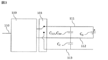
- センサ配線と前記センサ配線のすぐそばに配置された補完配線とを含む少なくとも2つの配線を有するインターフェース回路に接続された容量センサが出力する容量センサ測定値上の配線容量変化の影響を打ち消す方法であって、
前記センサ配線から全センサ容量値を取得し、
前記補完配線から全補完配線容量値を取得し、
取得した前記全センサ容量値から、取得した前記全補完配線容量値であって、重み係数をかけあわせた前記全補完配線容量値を差し引くことによって、補完済センサ容量値を算出し、
前記インターフェース回路の出力端子において前記補完済センサ容量値に対応する電気信号を出力し、
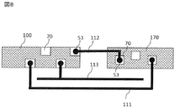
前記補完配線は、前記インターフェース回路にのみ電気接続され、
前記重み係数を、
第1測定において、第1全センサ容量値と第1全補完配線容量値とを測定するステップと、
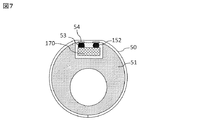
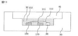
前記容量センサと前記容量センサの配線とを、空気より大きい誘電率を有するモールド材で覆うことによるそれらの周囲環境における比誘電率の変化にさらすステップと、
前記容量センサと前記容量センサの配線とを、前記モールド材に起因するそれらの周囲環境における前記比誘電率の変化にさらした後、第2測定において、第2全センサ容量値と第2全補完配線容量値とを測定するステップと、
前記第1全センサ容量値と前記第2全センサ容量値との間の変化に基づいて、測定した全センサ容量の変化を算出し、前記第1全補完配線容量値と前記第2全補完配線容量値との間の変化に基づいて、測定した全補完配線容量の変化を算出するステップと、
前記測定した全センサ容量の変化を前記測定した全補完配線容量の変化で割ることにより前記重み係数を算出するステップとによって取得することにより、
前記重み係数を用いて算出された前記補完済センサ容量値は、前記容量センサと前記インターフェース回路とその配線との周囲環境における比誘電率の変化に依存しない
方法。 - さらに、
前記インターフェース回路の第1入力端子において前記センサ配線が接合され、前記インターフェース回路の第2入力端子において共通配線が接合される場合、前記インターフェース回路によって前記全センサ容量値を取得し、
前記インターフェース回路の第1入力端子において前記補完配線が接合され、前記インターフェース回路の第2入力端子において前記共通配線が接合される場合、前記インターフェース回路によって前記全補完配線容量値を取得する
請求項1に記載の方法。 - さらに、
前記全センサ容量値を取得するための前記センサ配線と、前記全補完配線容量値を取得するための前記補完配線とのうちのいずれか一つに接続されるように前記インターフェース回路の第1入力端子を多重化し、
前記多重化は、10ミリ秒から10分の範囲における頻度で発生する
請求項2に記載の方法。 - さらに、
前記インターフェース回路の第1入力端子において積分ベース容量のみが接合され、前記インターフェース回路の第2入力端子において共通配線が接合される場合、前記インターフェース回路によって積分ベース容量値を取得し、
前記インターフェース回路の第1入力端子において前記センサ配線が接合され、前記インターフェース回路の第2入力端子において前記共通配線が接合される場合、前記インターフェース回路によって、前記積分ベース容量値を含む前記全センサ容量値を取得し、
前記インターフェース回路の第1入力端子において前記補完配線が接合され、前記インターフェース回路の第2入力端子において前記共通配線が接合される場合、前記インターフェース回路によって、前記積分ベース容量値を含む前記全補完配線容量値を取得し、
前記補完済センサ容量値を算出する前に、前記積分ベース容量値を前記全センサ容量値と前記全補完配線容量値の両方から差し引く
請求項1に記載の方法。 - さらに、
前記全センサ容量値を取得するための前記センサ配線と、前記全補完配線容量値を取得するための前記補完配線と、前記積分ベース容量値を取得するための前記積分ベース容量とのうちのいずれか一つに接続されるように前記インターフェース回路の第1入力端子を多重化し、
前記多重化は、10ミリ秒から10分の範囲における頻度で発生する
請求項4に記載の方法。 - さらに、
前記補完配線と前記共通配線との間の容量が前記センサ配線と前記共通配線との間の容量と実質的に等しくなるように、前記補完配線を配置する
請求項2から5のいずれか1項に記載の方法。 - 前記重み係数を、
校正関数を定義するステップと、
第1全センサ容量値と、第1全補完容量値と、第1基準圧力値とを測定するステップと、
ダミー重み係数を用いて、前記第1全センサ容量値と前記第1全補完容量値とに基づいて、第1補完済センサ容量値を算出するステップと、
前記校正関数を用いて、前記第1補完済センサ容量値に対応する第1圧力値を算出する
ステップと、
前記容量センサと前記容量センサの配線とを、それらの周囲環境における比誘電率の変化にさらすステップと、
前記容量センサと前記容量センサの配線とをそれらの周囲環境における前記比誘電率の変化にさらした後、第2全センサ容量値と、第2全補完容量値と、第2基準圧力値とを測定するステップと、
前記第2全センサ容量値と前記第2全補完容量値とに基づいて、第2補完済センサ容量値を算出するステップと、
前記校正関数を用いて、前記第2補完済センサ容量値に基づいて第2圧力値を算出するステップと、
調節後の前記重み係数を用いて算出される第1圧力誤差が、同じ調節後の前記重み係数を用いて算出される第2圧力誤差と等しくなるように、前記第1補完済センサ容量値と前記第2補完済センサ容量値と前記第1圧力値と前記第2圧力値とを算出するのに用いられる前記重み係数を調節することにより前記重み係数を取得するステップとによって取得し、前記第1圧力誤差は、調節後の前記重み係数を用いて算出される前記第1圧力値と前記第1基準圧力値との差に等しく、前記第2圧力誤差は、調節後の前記重み係数を用いて算出される前記第2圧力値と前記第2基準圧力値との差に等しい
請求項1から6のいずれか1項に記載の方法。 - 容量センサとインターフェース回路とを備え、前記容量センサは、センサ配線と前記センサ配線のすぐそばに配置された補完配線とを含む少なくとも2つの配線を有する前記インターフェース回路に接続され、容量センサ測定値上の配線容量変化の影響を打ち消すように構成された装置であって、
前記センサ配線から前記容量センサの全センサ容量値を取得し、
前記補完配線から全補完配線容量値を取得し、
取得した前記全センサ容量値から、重み係数をかけ合わせた取得した前記全補完配線容量値を差し引くことによって、補完済センサ容量値を算出し、
前記インターフェース回路の出力端子において前記補完済センサ容量値に対応する電気信号を出力するように構成され、
前記補完配線は、前記インターフェース回路にのみ電気接続され、
前記容量センサと前記インターフェース回路とそれらの配線とは、空気より大きい誘電率を有するモールド材で覆われ、前記重み係数を、前記モールド材をつける前と後とに行われる容量値測定に基づいて定義するように構成することにより、
前記重み係数を用いて算出された前記補完済センサ容量値は、前記容量センサと前記インターフェース回路とその配線との周囲環境における比誘電率の変化に依存しない
装置。 - 前記インターフェース回路の第2入力端子において共通配線が接合され、さらに、
前記全センサ容量値を取得するための前記センサ配線と、
前記全補完配線容量値を取得するための前記補完配線とのうちの
いずれか一つに接続されるように前記インターフェース回路の第1入力端子を多重化するよう構成されたスイッチを備え、
前記多重化は、10ミリ秒から10分の範囲における頻度で発生する
請求項8に記載の装置。 - 前記インターフェース回路の第2入力端子において共通配線が接合され、さらに、
積分ベース容量値を取得するための積分ベース容量のみと、
前記積分ベース容量値を含む前記全センサ容量値を取得するための前記センサ配線と、
前記積分ベース容量値を含む前記全補完配線容量値を取得するための前記補完配線とのうちの
いずれか一つに接続されるように前記インターフェース回路の第1入力端子を多重化するよう構成されたスイッチを備え、
前記多重化は、10ミリ秒から10分の範囲における頻度で発生し、さらに、前記補完済センサ容量値を算出する前に、前記積分ベース容量値を前記全センサ容量値と前記全補完配線容量値の両方から差し引くように構成された
請求項8に記載の装置。 - 前記補完配線と前記共通配線との間の容量が前記センサ配線と前記共通配線との間の容量と実質的に等しくなるように、前記補完配線は配置される
請求項9又は10に記載の装置。 - さらに、
第1測定において、第1全センサ容量値と第1全補完配線容量値とを測定し、
前記容量センサと前記容量センサの配線とをそれらの周囲環境における比誘電率の変化にさらした後、第2測定において、第2全センサ容量値と第2全補完配線容量値とを測定し、
前記第1全センサ容量値と前記第2全センサ容量値との間の変化に基づいて、測定した全センサ容量の変化を算出し、前記第1全補完配線容量値と前記第2全補完配線容量値との間の変化に基づいて、測定した全補完配線容量の変化を算出し、
前記測定した全センサ容量の変化を前記測定した全補完配線容量の変化で割ることにより前記重み係数を算出するように構成された
請求項9から11のいずれか1項に記載の装置。 - さらに、
校正関数を定義し、
第1全センサ容量値と、第1全補完容量値と、第1基準圧力値とを測定し、
ダミー重み係数を用いて、前記第1全センサ容量値と前記第1全補完容量値とに基づいて、第1補完済センサ容量値を算出し、
前記校正関数を用いて、前記第1補完済センサ容量値に対応する第1圧力値を算出し、
前記容量センサと前記容量センサの配線とをそれらの周囲環境における比誘電率の変化にさらした後、第2全センサ容量値と、第2全補完容量値と、第2基準圧力値とを測定し、
前記第2全センサ容量値と前記第2全補完容量値とに基づいて、第2補完済センサ容量値を算出し、
前記校正関数を用いて、前記第2補完済センサ容量値に基づいて第2圧力値を算出し、
調節後の前記重み係数を用いて算出される第1圧力誤差が、同じ調節後の前記重み係数を用いて算出される第2圧力誤差と等しくなるように、前記第1補完済センサ容量値と前記第2補完済センサ容量値と前記第1圧力値と前記第2圧力値とを算出するのに用いられる前記重み係数を調節することにより前記重み係数を取得するように構成され、前記第1圧力誤差は、調節後の前記重み係数を用いて算出される前記第1圧力値と前記第1基準圧力値との差に等しく、前記第2圧力誤差は、調節後の前記重み係数を用いて算出される前記第2圧力値と前記第2基準圧力値との差に等しい
請求項9から12のいずれか1項に記載の装置。
Applications Claiming Priority (2)
| Application Number | Priority Date | Filing Date | Title |
|---|---|---|---|
| FI20176012 | 2017-11-13 | ||
| FI20176012 | 2017-11-13 |
Publications (2)
| Publication Number | Publication Date |
|---|---|
| JP2019105626A JP2019105626A (ja) | 2019-06-27 |
| JP6696552B2 true JP6696552B2 (ja) | 2020-05-20 |
Family
ID=64267580
Family Applications (1)
| Application Number | Title | Priority Date | Filing Date |
|---|---|---|---|
| JP2018206982A Active JP6696552B2 (ja) | 2017-11-13 | 2018-11-02 | 配線容量キャンセル方法および配線容量キャンセル装置 |
Country Status (3)
| Country | Link |
|---|---|
| US (1) | US11248977B2 (ja) |
| EP (1) | EP3483564B1 (ja) |
| JP (1) | JP6696552B2 (ja) |
Family Cites Families (12)
| Publication number | Priority date | Publication date | Assignee | Title |
|---|---|---|---|---|
| BE551788A (ja) | 1955-10-19 | |||
| GB2071852A (en) | 1980-03-12 | 1981-09-23 | Rolls Royce | Capacitance frequency modulation probe for blade tip clearance measurement |
| US5431057A (en) * | 1990-02-12 | 1995-07-11 | Fraunhofer-Gesellschaft Zur Forderung Der Angewandten Forschung E.V. | Integratable capacitative pressure sensor |
| DE4004179A1 (de) * | 1990-02-12 | 1991-08-14 | Fraunhofer Ges Forschung | Integrierbarer, kapazitiver drucksensor und verfahren zum herstellen desselben |
| JP3567089B2 (ja) * | 1998-10-12 | 2004-09-15 | 株式会社日立製作所 | 静電容量式圧力センサ |
| JP2009257916A (ja) * | 2008-04-16 | 2009-11-05 | Oki Semiconductor Co Ltd | 静電容量型圧力センサ及び静電容量の補償信号の提供方法 |
| JP2013024808A (ja) * | 2011-07-25 | 2013-02-04 | Japan Aerospace Exploration Agency | 計測装置および計測方法 |
| US20140026642A1 (en) * | 2012-07-25 | 2014-01-30 | John O. O'Connell | Capacitive sensor comprising differing unit cell structures |
| FI125447B (en) | 2013-06-04 | 2015-10-15 | Murata Manufacturing Co | Improved pressure sensor |
| US9285404B2 (en) * | 2013-08-15 | 2016-03-15 | Freescale Semiconductor, Inc. | Test structure and methodology for estimating sensitivity of pressure sensors |
| EP2988122B1 (en) | 2014-08-20 | 2019-04-24 | ams international AG | Capacitive sensor |
| CN106403922A (zh) | 2015-07-31 | 2017-02-15 | 立锜科技股份有限公司 | 具有电性补偿的微机电元件及其读取电路 |
-
2018
- 2018-11-02 JP JP2018206982A patent/JP6696552B2/ja active Active
- 2018-11-07 EP EP18204798.5A patent/EP3483564B1/en active Active
- 2018-11-12 US US16/186,966 patent/US11248977B2/en active Active
Also Published As
| Publication number | Publication date |
|---|---|
| JP2019105626A (ja) | 2019-06-27 |
| EP3483564A1 (en) | 2019-05-15 |
| US20190145843A1 (en) | 2019-05-16 |
| US11248977B2 (en) | 2022-02-15 |
| EP3483564B1 (en) | 2021-07-14 |
Similar Documents
| Publication | Publication Date | Title |
|---|---|---|
| US11768122B2 (en) | Liquid detection in a sensor environment and remedial action thereof | |
| US10398343B2 (en) | Perspiration sensor | |
| CN106298746B (zh) | 用于集成电子模块的垂直磁性屏障 | |
| US8330236B2 (en) | Isolation channel improving measurement accuracy of MEMS devices | |
| US9709446B2 (en) | Module for integration into a mobile terminal to measure the ambient temperature | |
| RU2015116636A (ru) | Дозирующее устройство для введения лекарственных препаратов | |
| CN106053915A (zh) | 电流传感器 | |
| US7019540B2 (en) | Electrostatic capacitance detection circuit and microphone device | |
| JP6533536B2 (ja) | 容量感知システム内のフィードラインへの標的物体の結合の補償 | |
| US7005865B2 (en) | Circuit and method for impedance detection | |
| US7034551B2 (en) | Electrostatic capacitance detection circuit and microphone device | |
| JP6696552B2 (ja) | 配線容量キャンセル方法および配線容量キャンセル装置 | |
| TWI466599B (zh) | 電路板及電路板內建之元件的測試方法 | |
| EP3372969A1 (en) | Temperature measurement integrated circuit with flexible cable and sensing element | |
| KR101559154B1 (ko) | 압력센서 패키지 및 그 제조 방법 | |
| JP6522740B2 (ja) | 荷重計測装置 | |
| US20260036441A1 (en) | In-situ capacitance detection for integrated circuits and mems sensors | |
| US10690706B2 (en) | Device for measuring an electrical quantity of one phase of an AC electric current of an overhead electrical network | |
| WO2006113325A2 (en) | Integrated tilt sensor | |
| CN109416291A (zh) | 压力差传感器 | |
| Dogan et al. | Miniaturized Multi Sensor Implant for Monitoring of Hemodynamic Parameters | |
| CN121323753A (zh) | 可修整流体液位感测条 | |
| CN121740968A (zh) | 具有湿度传感器的封装mems器件 | |
| Belavic et al. | Thick Film Interconnections for Sensor Applications | |
| TH124034A (th) | เซ็นเซอร์อินฟราเรด |
Legal Events
| Date | Code | Title | Description |
|---|---|---|---|
| A621 | Written request for application examination |
Free format text: JAPANESE INTERMEDIATE CODE: A621 Effective date: 20190304 |
|
| A131 | Notification of reasons for refusal |
Free format text: JAPANESE INTERMEDIATE CODE: A131 Effective date: 20191210 |
|
| A977 | Report on retrieval |
Free format text: JAPANESE INTERMEDIATE CODE: A971007 Effective date: 20191211 |
|
| A601 | Written request for extension of time |
Free format text: JAPANESE INTERMEDIATE CODE: A601 Effective date: 20200207 |
|
| A521 | Request for written amendment filed |
Free format text: JAPANESE INTERMEDIATE CODE: A523 Effective date: 20200217 |
|
| A131 | Notification of reasons for refusal |
Free format text: JAPANESE INTERMEDIATE CODE: A131 Effective date: 20200303 |
|
| A521 | Request for written amendment filed |
Free format text: JAPANESE INTERMEDIATE CODE: A523 Effective date: 20200309 |
|
| TRDD | Decision of grant or rejection written | ||
| A01 | Written decision to grant a patent or to grant a registration (utility model) |
Free format text: JAPANESE INTERMEDIATE CODE: A01 Effective date: 20200324 |
|
| A61 | First payment of annual fees (during grant procedure) |
Free format text: JAPANESE INTERMEDIATE CODE: A61 Effective date: 20200406 |
|
| R150 | Certificate of patent or registration of utility model |
Ref document number: 6696552 Country of ref document: JP Free format text: JAPANESE INTERMEDIATE CODE: R150 |