EP3483564A1 - Method and apparatus for cancelling interconnection capacitance - Google Patents
Method and apparatus for cancelling interconnection capacitance Download PDFInfo
- Publication number
- EP3483564A1 EP3483564A1 EP18204798.5A EP18204798A EP3483564A1 EP 3483564 A1 EP3483564 A1 EP 3483564A1 EP 18204798 A EP18204798 A EP 18204798A EP 3483564 A1 EP3483564 A1 EP 3483564A1
- Authority
- EP
- European Patent Office
- Prior art keywords
- interconnection
- sensor
- capacitance value
- total
- compensating
- Prior art date
- Legal status (The legal status is an assumption and is not a legal conclusion. Google has not performed a legal analysis and makes no representation as to the accuracy of the status listed.)
- Granted
Links
- 238000000034 method Methods 0.000 title claims abstract description 51
- 230000000694 effects Effects 0.000 claims abstract description 7
- 238000005259 measurement Methods 0.000 claims description 17
- 239000000463 material Substances 0.000 description 26
- 238000002474 experimental method Methods 0.000 description 10
- 238000000465 moulding Methods 0.000 description 10
- 230000007613 environmental effect Effects 0.000 description 6
- 229920001296 polysiloxane Polymers 0.000 description 6
- 150000003839 salts Chemical class 0.000 description 6
- XLYOFNOQVPJJNP-UHFFFAOYSA-N water Substances O XLYOFNOQVPJJNP-UHFFFAOYSA-N 0.000 description 6
- 238000006243 chemical reaction Methods 0.000 description 5
- 239000004065 semiconductor Substances 0.000 description 4
- 238000007667 floating Methods 0.000 description 3
- 238000009434 installation Methods 0.000 description 3
- 229910000679 solder Inorganic materials 0.000 description 3
- 101100119135 Mus musculus Esrrb gene Proteins 0.000 description 2
- 238000009530 blood pressure measurement Methods 0.000 description 2
- 239000003990 capacitor Substances 0.000 description 2
- 239000000919 ceramic Substances 0.000 description 2
- 239000013065 commercial product Substances 0.000 description 2
- 238000005516 engineering process Methods 0.000 description 2
- 238000004519 manufacturing process Methods 0.000 description 2
- 230000003278 mimic effect Effects 0.000 description 2
- 238000012545 processing Methods 0.000 description 2
- 238000002835 absorbance Methods 0.000 description 1
- 239000000853 adhesive Substances 0.000 description 1
- 230000001070 adhesive effect Effects 0.000 description 1
- 238000004458 analytical method Methods 0.000 description 1
- 230000000712 assembly Effects 0.000 description 1
- 238000000429 assembly Methods 0.000 description 1
- 230000036772 blood pressure Effects 0.000 description 1
- 210000001124 body fluid Anatomy 0.000 description 1
- 238000004364 calculation method Methods 0.000 description 1
- 239000004020 conductor Substances 0.000 description 1
- 230000003247 decreasing effect Effects 0.000 description 1
- 230000001419 dependent effect Effects 0.000 description 1
- 238000013461 design Methods 0.000 description 1
- 238000001514 detection method Methods 0.000 description 1
- 239000010432 diamond Substances 0.000 description 1
- 239000003989 dielectric material Substances 0.000 description 1
- 239000012530 fluid Substances 0.000 description 1
- 239000012778 molding material Substances 0.000 description 1
- 230000001681 protective effect Effects 0.000 description 1
- 230000000717 retained effect Effects 0.000 description 1
- 238000005476 soldering Methods 0.000 description 1
- 239000000126 substance Substances 0.000 description 1
- 239000000758 substrate Substances 0.000 description 1
Images


Classifications
-
- G—PHYSICS
- G01—MEASURING; TESTING
- G01D—MEASURING NOT SPECIALLY ADAPTED FOR A SPECIFIC VARIABLE; ARRANGEMENTS FOR MEASURING TWO OR MORE VARIABLES NOT COVERED IN A SINGLE OTHER SUBCLASS; TARIFF METERING APPARATUS; MEASURING OR TESTING NOT OTHERWISE PROVIDED FOR
- G01D18/00—Testing or calibrating apparatus or arrangements provided for in groups G01D1/00 - G01D15/00
-
- G—PHYSICS
- G01—MEASURING; TESTING
- G01D—MEASURING NOT SPECIALLY ADAPTED FOR A SPECIFIC VARIABLE; ARRANGEMENTS FOR MEASURING TWO OR MORE VARIABLES NOT COVERED IN A SINGLE OTHER SUBCLASS; TARIFF METERING APPARATUS; MEASURING OR TESTING NOT OTHERWISE PROVIDED FOR
- G01D5/00—Mechanical means for transferring the output of a sensing member; Means for converting the output of a sensing member to another variable where the form or nature of the sensing member does not constrain the means for converting; Transducers not specially adapted for a specific variable
- G01D5/12—Mechanical means for transferring the output of a sensing member; Means for converting the output of a sensing member to another variable where the form or nature of the sensing member does not constrain the means for converting; Transducers not specially adapted for a specific variable using electric or magnetic means
- G01D5/14—Mechanical means for transferring the output of a sensing member; Means for converting the output of a sensing member to another variable where the form or nature of the sensing member does not constrain the means for converting; Transducers not specially adapted for a specific variable using electric or magnetic means influencing the magnitude of a current or voltage
- G01D5/24—Mechanical means for transferring the output of a sensing member; Means for converting the output of a sensing member to another variable where the form or nature of the sensing member does not constrain the means for converting; Transducers not specially adapted for a specific variable using electric or magnetic means influencing the magnitude of a current or voltage by varying capacitance
-
- G—PHYSICS
- G01—MEASURING; TESTING
- G01L—MEASURING FORCE, STRESS, TORQUE, WORK, MECHANICAL POWER, MECHANICAL EFFICIENCY, OR FLUID PRESSURE
- G01L27/00—Testing or calibrating of apparatus for measuring fluid pressure
- G01L27/002—Calibrating, i.e. establishing true relation between transducer output value and value to be measured, zeroing, linearising or span error determination
- G01L27/005—Apparatus for calibrating pressure sensors
-
- G—PHYSICS
- G01—MEASURING; TESTING
- G01L—MEASURING FORCE, STRESS, TORQUE, WORK, MECHANICAL POWER, MECHANICAL EFFICIENCY, OR FLUID PRESSURE
- G01L9/00—Measuring steady of quasi-steady pressure of fluid or fluent solid material by electric or magnetic pressure-sensitive elements; Transmitting or indicating the displacement of mechanical pressure-sensitive elements, used to measure the steady or quasi-steady pressure of a fluid or fluent solid material, by electric or magnetic means
- G01L9/02—Measuring steady of quasi-steady pressure of fluid or fluent solid material by electric or magnetic pressure-sensitive elements; Transmitting or indicating the displacement of mechanical pressure-sensitive elements, used to measure the steady or quasi-steady pressure of a fluid or fluent solid material, by electric or magnetic means by making use of variations in ohmic resistance, e.g. of potentiometers, electric circuits therefor, e.g. bridges, amplifiers or signal conditioning
- G01L9/04—Measuring steady of quasi-steady pressure of fluid or fluent solid material by electric or magnetic pressure-sensitive elements; Transmitting or indicating the displacement of mechanical pressure-sensitive elements, used to measure the steady or quasi-steady pressure of a fluid or fluent solid material, by electric or magnetic means by making use of variations in ohmic resistance, e.g. of potentiometers, electric circuits therefor, e.g. bridges, amplifiers or signal conditioning of resistance-strain gauges
-
- G—PHYSICS
- G01—MEASURING; TESTING
- G01L—MEASURING FORCE, STRESS, TORQUE, WORK, MECHANICAL POWER, MECHANICAL EFFICIENCY, OR FLUID PRESSURE
- G01L9/00—Measuring steady of quasi-steady pressure of fluid or fluent solid material by electric or magnetic pressure-sensitive elements; Transmitting or indicating the displacement of mechanical pressure-sensitive elements, used to measure the steady or quasi-steady pressure of a fluid or fluent solid material, by electric or magnetic means
- G01L9/12—Measuring steady of quasi-steady pressure of fluid or fluent solid material by electric or magnetic pressure-sensitive elements; Transmitting or indicating the displacement of mechanical pressure-sensitive elements, used to measure the steady or quasi-steady pressure of a fluid or fluent solid material, by electric or magnetic means by making use of variations in capacitance, i.e. electric circuits therefor
-
- G—PHYSICS
- G01—MEASURING; TESTING
- G01N—INVESTIGATING OR ANALYSING MATERIALS BY DETERMINING THEIR CHEMICAL OR PHYSICAL PROPERTIES
- G01N27/00—Investigating or analysing materials by the use of electric, electrochemical, or magnetic means
- G01N27/02—Investigating or analysing materials by the use of electric, electrochemical, or magnetic means by investigating impedance
- G01N27/22—Investigating or analysing materials by the use of electric, electrochemical, or magnetic means by investigating impedance by investigating capacitance
- G01N27/228—Circuits therefor
-
- G—PHYSICS
- G01—MEASURING; TESTING
- G01N—INVESTIGATING OR ANALYSING MATERIALS BY DETERMINING THEIR CHEMICAL OR PHYSICAL PROPERTIES
- G01N27/00—Investigating or analysing materials by the use of electric, electrochemical, or magnetic means
- G01N27/02—Investigating or analysing materials by the use of electric, electrochemical, or magnetic means by investigating impedance
- G01N27/22—Investigating or analysing materials by the use of electric, electrochemical, or magnetic means by investigating impedance by investigating capacitance
- G01N27/223—Investigating or analysing materials by the use of electric, electrochemical, or magnetic means by investigating impedance by investigating capacitance for determining moisture content, e.g. humidity
Definitions
- the present invention relates to a method related to capacitive sensors. More particularly, the invention relates to a method for canceling interconnection capacitance of a capacitive sensor caused by environmental conditions and an apparatus configured to perform such method.
- capacitive sensor refers to a sensor configured to detect various physical quantities.
- the measured physical quantity causes a change in a capacitance of the sensor, which can be detected with electronic circuitry and converted for example into digital data.
- Examples of capacitive sensors are for example capacitive pressure sensors, accelerometers, humidity sensors and chemical sensors.
- an interconnection from a circuitry performing analysis of capacitance values provided by the sensor circuitry often introduces an additional parallel capacitance, which may depend on environmental conditions like temperature and humidity.
- This interconnection capacitance may cause significant error in the detected capacitance value, and thus error in the detection of the physical quantity measured by the capacitive sensor.
- Many commonly used dielectric materials are quite unstable with respect to change in environmental conditions. For example, silicone gel that gives excellent protection from fluids in the environment absorbs quite a lot of moisture, which will change the silicone gel's relative permittivity. Relative permittivity of a material is expressed by its dielectric constant. Thus, a change of the relative permittivity is indicated by a change of the dielectric constant.
- the effect of moisture absorbance and the caused change of dielectric constant is quite rapid, varying from minutes to hours. In other materials the change of dielectric constant may be much slower.
- the change in environmental conditions will change the apparent total sensor capacitance and this change is impossible to distinguish from the change of the physical quantity the sensor is supposed to measure, such as atmospheric pressure or blood pressure.
- An object is to provide a method and an apparatus so as to solve the problem of canceling changes in interconnection capacitance between a capacitive sensor and an interface circuitry due to changes of the relative permittivity without special shield layers.
- the objects of the present invention are achieved with a method according to the characterizing portion of claim 1.
- the objects of the present invention are further achieved with an apparatus according to the characterizing portion of claim 11.
- the present invention is based on the idea of introducing a compensating interconnection that enables fully compensating the amount of change of interconnection capacitance in a sensor interconnection due to changes of relative permittivity in its environment.
- a compensating interconnection capacitance value is obtained, and a weight coefficient is determined that is used to multiply the compensating interconnection capacitance value before subtracting the multiplied compensating interconnection capacitance value from an obtained total sensor capacitance value in order to receive a compensated sensor capacitance value.
- the present invention has the advantage that it enables essentially removing any sensor interconnection capacitance caused error from an output signal of a capacitive sensor. Accuracy of sensing results achieved with the capacitive sensor is thus improved.
- a method for cancelling effects of changes in interconnection capacitances on capacitive sensor readings provided by a capacitive sensor is provided.
- the capacitive sensor is connected with an interface circuitry with at least two interconnections comprising a sensor interconnection and a compensating interconnection.
- the method comprises obtaining a total sensor capacitance value from the capacitive sensor, obtaining a total compensating interconnection capacitance value from the compensating interconnection, calculating a compensated sensor capacitance value by reducing the obtained total compensating interconnection capacitance value multiplied with a weight coefficient from the obtained total sensor capacitance value, and providing an electrical signal at an output of the interface circuitry that corresponds to the compensated sensor capacitance value.
- the compensated sensor capacitance value is independent of changes of relative permittivity in the immediate environment of the capacitive sensor, the interface circuitry and the interconnections thereof.
- the method further comprises connecting the interface circuitry to the compensating interconnection disposed at the immediate vicinity of the sensor interconnection for obtaining the total compensating interconnection capacitance value.
- the compensating interconnection is electrically connected only to the interface circuitry.
- the method further comprises obtaining, by the interface circuitry, the total sensor capacitance value when the sensor interconnection is coupled at its first input and a common interconnection is coupled at its second input, and obtaining, by the interface circuitry, the total compensating interconnection capacitance value when the compensating interconnection is coupled at its first input and the common interconnection is coupled at its second input.
- the method further comprises multiplexing the first input of the interface circuitry to be connected to one of the sensor interconnection for obtaining the total sensor interconnection capacitance value, and the compensating interconnection for obtaining the total compensating interconnection capacitance value.
- the multiplexing occurs at a frequency in a range between 10 milliseconds and 10 minutes.
- the method further comprises obtaining, by the interface circuitry, an integrating base capacitance value when only an integrating base capacitance is coupled at its first input and a common interconnection is coupled at its second input, obtaining, by the interface circuitry, the total sensor capacitance value when the sensor interconnection is coupled at its first input and the common interconnection is coupled at its second input, wherein the total sensor capacitance value includes the integrating base capacitance value, and obtaining, by the interface circuitry, the total compensating interconnection capacitance value when the compensating interconnection is coupled at its first input and the common interconnection is coupled at its second input, wherein the total compensating interconnection capacitance value includes the integrating base capacitance value.
- the method further comprises subtracting the integrating base capacitance value from both the total sensor interconnection capacitance value and the total compensating interconnection capacitance value before calculating the compensated sensor capacitance.
- the method further comprises multiplexing the first input of the interface circuitry to be connected to one of the sensor interconnection for obtaining the total sensor interconnection capacitance value, the compensating interconnection for obtaining the total compensating interconnection capacitance value, and the integrating base capacitance for obtaining the integrating base capacitance value.
- the multiplexing occurs at a frequency in a range between 10 milliseconds and 10 minutes.
- the method further comprises disposing the compensating interconnection so that a capacitance between the compensating interconnection and the common interconnection is essentially equal to a capacitance between the sensor interconnection and the common interconnection.
- the method comprises obtaining the weight coefficient by steps of measuring a first total sensor capacitance value and a first total compensating interconnection capacitance value in a first measurement, subjecting the capacitive sensor and its interconnections to a change of relative permittivity in their immediate environment, measuring a second total sensor capacitance value and a second total compensating interconnection capacitance value in a second measurement after subjecting the capacitive sensor and its interconnections to the change of relative permittivity in their immediate environment, calculating a change of the measured total sensor capacitance based on the change between the first and the second total sensor capacitance values, and a change of the measured compensating interconnection capacitance based on the change between the first and the second total compensating interconnection capacitance values; and calculating the weight coefficient by dividing the change of the measured total sensor capacitance by the change of the measured compensating interconnection capacitance.
- the method comprises obtaining the weight coefficient by steps of defining a calibration function, measuring a first total sensor capacitance value, a first total compensating capacitance value and a first reference pressure value, calculating a first compensated sensor capacitance value based on the first total sensor capacitance value and the first total compensating capacitance value using a dummy weight coefficient, calculating, using the calibration function, a first pressure value corresponding to the first compensated sensor capacitance value, subjecting the capacitive sensor and its interconnections to a change of relative permittivity in their immediate environment, measuring a second total sensor capacitance value, a second total compensating capacitance value and a second reference pressure value after subjecting the capacitive sensor and its interconnections to the change of relative permittivity in their immediate environment, calculating a second compensated sensor capacitance value based on the second total sensor capacitance value and the second total compensating capacitance value, calculating, using the calibration function, a second pressure value based on the second compensated sensor capacitance value
- an apparatus configured to cancel effects of changes in interconnection capacitances on capacitive sensor readings.
- the apparatus comprises at least the capacitive sensor and an interface circuitry.
- the capacitive sensor is connected to the interface circuitry with at least two interconnections comprising a sensor interconnection and a compensating interconnection.
- the apparatus is configured to obtain a total sensor capacitance value from the capacitive sensor, obtain a total compensating interconnection capacitance value from the compensating interconnection, calculate a compensated sensor capacitance value by reducing the obtained total compensating interconnection capacitance value multiplied with a weight coefficient from the obtained total sensor capacitance value, and provide at its output an electrical signal corresponding to the compensated sensor capacitance value.
- the compensated sensor capacitance value is independent of changes of relative permittivity in the immediate environment of the capacitive sensor, the interface circuitry and the interconnections thereof.
- the compensating interconnection is disposed at the immediate vicinity of the sensor interconnection.
- the interface circuitry is configured to be connected to the compensating interconnection for obtaining the total compensating interconnection capacitance value.
- the compensating interconnection is electrically connected only to the interface circuitry.
- a common interconnection is coupled at a second input of the interface circuitry.
- the apparatus further comprises a switch configured to multiplex a first input of the interface circuitry to be connected to one of the sensor interconnection for obtaining the total sensor interconnection capacitance value, and the compensating interconnection for obtaining the total compensating interconnection capacitance value.
- the multiplexing occurs at a frequency in a range between 10 milliseconds and 10 minutes.
- a common interconnection is coupled at a second input of the interface circuitry.
- the apparatus further comprises a switch configured to multiplex a first input of the interface circuitry to be connected to one of only an integrating base capacitance for obtaining an integrating base capacitance value, the sensor interconnection for obtaining the total sensor interconnection capacitance value that includes the integrating base capacitance value and the compensating interconnection for obtaining the total compensating interconnection capacitance value that includes the integrating base capacitance value.
- the multiplexing occurs at a frequency in a range between 10 milliseconds and 10 minutes.
- the apparatus is further configured to subtract the integrating base capacitance value from both the total sensor interconnection capacitance value and the total compensating interconnection capacitance value before calculating the compensated sensor capacitance.
- the compensating interconnection is disposed so that a capacitance between the compensating interconnection and the common interconnection is essentially equal to a capacitance between the sensor interconnection and the common interconnection.
- the apparatus is further configured to measure a first total sensor capacitance value and a first total compensating interconnection capacitance value in a first measurement, to measure a second total sensor capacitance value and a second total compensating interconnection capacitance value in a second measurement after the capacitive sensor and its interconnections have been subjected to a change of relative permittivity in their immediate environment, to calculate a change of the measured total sensor capacitance based on the change between the first and the second total sensor capacitance values, to calculated a change of the measured compensating interconnection capacitance based on the change between the first and the second total compensating interconnection capacitance values, and to calculate the weight coefficient by dividing the change of the measured total sensor capacitance by the change of the measured compensating interconnection capacitance.
- the apparatus is further configured to define a calibration function, to measure a first total sensor capacitance value, a first total compensating capacitance value and a first reference pressure value, to calculate a first compensated sensor capacitance value based on the first total sensor capacitance value and the first total compensating capacitance value using a dummy weight coefficient, to calculate, using a calibration function, a first pressure value corresponding to the first compensated sensor capacitance value, to measure a second total sensor capacitance value, a second total compensating capacitance value and a second reference pressure value after the capacitive sensor and its interconnections have been subjected to a change of relative permittivity in their immediate environment, to calculate a second compensated sensor capacitance value based on the second total sensor capacitance value and the second total compensating capacitance value and to calculate, using the calibration function, a second pressure value based on the second compensated sensor capacitance value, and to obtain the weight coefficient by adjusting the weight coefficient used for calculating the
- circuitry refers to any electronic device capable of receiving, producing or processing electrical signals.
- a sensor interconnection couples a sensor to an electronic circuitry.
- the electronic circuity may be configured at least to process sensor signals, also known as sensor readings received from the sensor.
- This invention assumes that there is an additional compensating interconnection that can be interchanged with the sensor interconnection at an electronic circuitry that has a multiplexed input.
- the compensating interconnection may also be called a dummy interconnection, since it does not actually interconnect any electronic circuitries.
- the other end of this compensating interconnection is not connected to anything and it should be dimensioned as similar to the sensor interconnection as possible and also disposed into a position as similar to the sensor interconnection as possible. Multiplexing the input allows measuring a capacitance value of the compensating interconnection.
- This compensating interconnection capacitance can't, however, be subtracted as such from the total detected sensor capacitance value, since in a practical design and implementation taking the production tolerances into account the compensating interconnection can never exactly duplicate the sensor interconnection.
- the invention is based on using a mold material to fill empty surfaces and spaces near the sensor, circuit and interconnections.
- the mold material may also be called filling material.
- the mold material preferably has a dielectric constant ⁇ r greater than 1, which is the dielectric constant of air. Molding will change the sensor interconnection capacitance and thus the detected total sensor capacitance C Stot and the detected compensating interconnection capacitance C Ctot .
- the compensated sensor capacitance C Scomp thus obtained is essentially free of the influence of the dielectric constant ⁇ r of the mold material and, if the interconnections are properly designed, also any other interconnection capacitance components that are not due to the mold material are cancelled.
- the total sensor capacitance C Stot can be defined as a combination of three components: the sensor capacitance Cs, the interconnection capacitance due to the mold cavity C SM and interconnection capacitance due to other materials Cso.
- the compensating interconnection capacitance C Ctot may be defined as a combination of two components: the interconnection capacitance due to the mold cavity C CM and due to other materials C CO .
- C Stot C S + C SO + ⁇ r C SM
- C Ctot C CO + ⁇ r C CM where ⁇ r is the dielectric constant of the material in the mold cavity.
- the dielectric constant of the air in the mold cavity ⁇ r 1 and after molding the dielectric constant ⁇ r has a value of the molding material.
- the dielectric constant may be approximately 2.5 for some silicone materials.
- C CO C CM ⁇ C SO C SM and for the compensated sensor capacitance we get from equation (8)
- C Scomp C S which means perfect cancelling of the sensor interconnection capacitance.
- Reference to designing the compensating interconnection very similar to the sensor interconnection means that area and distance of the compensating interconnection may differ somewhat from those of the sensor interconnection, but the proportions of the interconnections are retained alike.
- the key target of maintaining the proportions of the interconnections alike is that the capacitance between the sensor interconnection to a reference interconnection and capacitance between the compensating interconnection to the same reference interconnection are essentially equal. With essentially equal capacitances we mean that the capacitances are designed to be as equal as practically possible.
- FIG. 1 illustrates a flow chart of a first exemplary process for defining the weight coefficient k.
- the total sensor capacitance is measured, and in the phase 11 the total compensating interconnection capacitance is measured.
- phases 10 and 11 may be performed in any order without departing from the scope.
- the interconnections are covered in the phase 12 with a mold having a dielectric constant ⁇ r higher than that of the air.
- the molding causes subjecting the sensor and its interconnections to a change of the relative permittivity and thus also a change of the dielectric constant in their immediate environment.
- change of the relative permittivity of material between plates of a capacitor causes a change of capacitance.
- phase 14 After applying the mold material in the phase 12, the total sensor capacitance is measured again in the phase 14 and the total compensating interconnection capacitance is measures again in the phase 15. Similar to phases 10 and 11, phases 14 and 15 may be performed in any order without departing from the scope.
- the environmental conditions relevant to the sensor e.g. the atmospheric pressure for a pressure sensor must be maintained the same during both the initial measurement before molding and the measurement after molding. Alternatively, the environmental conditions, e.g. pressure, must be recorded and the sensor calibration must be used to normalize the sensor capacitance to the initial value.
- the weight coefficient k is calculated based on the measurement results obtained in phases 10, 11, 14 and 15.
- Figure 2 illustrates a flow chart of a second exemplary process for defining the weight coefficient k.
- the mathematical basis for defining the weight coefficient k is the same as in the first exemplary process, but this method allows change in the ambient pressure during the definition process and is thus more feasible to be used in a manufacturing and calibration process of a commercial product.
- a calibration function P is defined for calibrating the pressure sensor in the phase 20.
- the total sensor capacitance and the total interconnection capacitance are measured at a number of pressure points and the capacitance and pressure values are recorded.
- the pressure values at the number of pressure points may be recorded with a second, calibrated pressure sensor.
- a mathematical calibration function P is defined for calculating the output pressure value from the compensated sensor capacitance value.
- the calibration function P is a function that gives the smallest average pressure error over the desired pressure range.
- the function may be a polynomial of capacitance values or inverse capacitance values or it may be a hyperbolic function of the capacitance value (i.e.
- the calibration function P is a function of the compensated sensor capacitance C Scomp and the weight coefficient k, and the result of the calibration function P is a pressure value p.
- a dummy weight coefficient k 0 is used in the calibration phase 20.
- the calibration function may be performed by any known type of processing device, for example a computer, a processor, a microprocessor, an application specific integrated circuit (ASIC) and so on.
- ASIC application specific integrated circuit
- the total sensor capacitance C Stot and the total compensating interconnection capacitance C Ctot are measured.
- the total sensor capacitance value is measured simultaneously with the measurement of a first reference pressure value with the reference pressure sensor in the phase 21' illustrated by the dashed box in the flow chart.
- a first compensated sensor capacitance C Scomp1 is calculated in the phase 22 using the equation (2) with the dummy weight coefficient k 0 used during the calibration phase 20.
- a first detected pressure value p is calculated in the phase 23 with the calibration function P using the first compensated sensor capacitance C Scomp1 and the dummy weight coefficient k 0 .
- Equation (12) for a first pressure error P err1 P C Scomp 1 , k 0 ⁇ pl ⁇ 0
- the first pressure error may be calculated at any phase after obtaining the first pressure value and the first reference pressure value for example for verifying the calibration function.
- the pressure and capacitance measurements of the phases 21 and 21' occur preferably essentially simultaneously, and the reference pressure sensor should be located near the sensor under calibration so that the ambient pressure is essentially the same for the both sensors.
- the first pressure error P err1 may also be calculated only during the phase 29.
- the sensor is then molded in the phase 24, covering the sensor with the protective filling, and thus subjecting the sensor and its interconnections to a change of relative permittivity and the dielectric constant in their immediate environment.
- the total sensor capacitance C Stot and the total compensating capacitance C Ctot are measured again in the phase 25, and a second compensated sensor capacitance C Scomp2 is calculated in the phase 26 using the equation (2).
- the ambient pressure may have changed to p2, since some time has passed since the first pressure measurement used for the calibration, and also because it may not be economically feasible to standardize the ambient pressure.
- the ambient pressure p2 is measured with the reference pressure sensor in the phase 25' preferably essentially simultaneously to measuring the total sensor capacitance and the total compensating capacitance in the phase 25 as illustrated with the dashed box in the flow chart.
- the total sensor capacitance value is measured simultaneously with the measurement of the reference pressure value with the reference pressure sensor.
- the first pressure error may be calculated at any phase after obtaining the second pressure value and the second reference pressure value for example for verifying the calibration function.
- the weight coefficient k is adjusted so that the newly calculated first pressure error P err1 equals with the second pressure error P err2 both being calculated with the adjusted weight coefficient k.
- the calibration function may be further updated using the original recorded calibration data points from phase 20 with the adjusted weight coefficient k defined in the phase 27.
- the updated calibration function P upd if the updated calibration function P upd is defined correctly, the difference between the first and the second obtained pressure values calculated from the first and second compensated sensor capacitances using the updated calibration function P upd and the weight coefficient k, and the respective first and second ambient pressures p1 and p2, becomes approximately zero.
- the updated calibration function P upd now includes both the information on the correct adjusted weight coefficient k and any other calibration parameters needed to obtain accurate pressure value readings.
- the updated calibration function P upd and the adjusted weight coefficient k may be applied to obtain a compensated and calibrated pressure value based on a total sensor capacitance value and a total interconnection capacitance value received from the pressure sensor and the dummy interconnection.
- FIG. 3 illustrates a general schematic of a circuitry used for implementation of the above described compensating method.
- An interface circuitry 100 comprises at least capacitance conversion unit configured to convert the capacitance value of a capacitor connected to it into an analog or digital output signal 110.
- the output signal 110 may be characterized as an electrical signal representing a value of a physical quantity. In case of a capacitive sensor, the output signal may be an analog or digital signal corresponding to or representing an obtained capacitance value.
- a switching unit 101 enables to connect either the total sensor capacitance C Stot or the total compensating interconnection capacitance C Ctot to the input of the capacitance conversion unit. Multiplexing, in other words switching between the two capacitances, should be done often enough depending on the speed of the changes of the dielectric constant in their environment. In some cases, the frequency maybe once in ten minutes and in other cases every millisecond.
- a sensor interconnection 111 is coupled to one multiplexed input of the switching unit 101, and it connects the sensor to capacitance conversion unit of the interface circuitry 100 via the switching unit 101.
- a compensating interconnection 113 is coupled to the other multiplexed input of the switching unit 101.
- a common interconnection 112 is preferably directly coupled to an input of the capacitance conversion unit of the interface circuitry 100.
- any other circuitry may be used to implement the functionalities of the figures 1 and 2 .
- Figure 4 illustrates a schematic of an exemplary implementation of a circuitry comprising a combined conversion unit and a switching unit.
- This implementation comprises of an integrating converter where a constant current I is fed from a current source 210 to the inverting input of an amplifier 220 and an integrating base capacitance is provided between the inverting input (-) and output of the amplifier 220.
- the output voltage provided at the output 110 will rise with a constant slope that is proportional to the integrating base capacitance. This slope may be measured with two threshold voltage level detectors and a pulse counter (not shown).
- the integrating base capacitance is a sum of a base capacitance 225 and either the total sensor capacitance C Stot or the total compensating interconnection capacitance C Ctot , depending on the position of the switch 101.
- the base capacitance 225 is needed since the value of the total compensating interconnection capacitance C Ctot may be very small and the slope of the output voltage may be very steep which may lead to an impractically short time period between two output voltage threshold levels.
- the known value of the base capacitance 225 is be subtracted from the total sensor capacitance C Stot and the total compensating interconnection capacitance C Ctot before applying equation (2). This is easily implemented by having a third position of the switch 101 with which only the base capacitance 225 switched to the converter.
- Figure 5 illustrates a flow chart of the process for calculating a compensated sensor capacitance.
- phase 41 the switching circuit is changed to couple with the interconnection towards the base capacitance, and the base capacitance is measured. This phase is needed only if a base capacitance is used as illustrated in the figure 4 . If there is no base capacitance to be measured, the phase 41 may be omitted.
- the switching circuit is changed to couple with the sensor interconnection, and the total sensor capacitance is measured.
- the switching circuit is changed to couple with the compensating interconnection, and the total compensating interconnection capacitance is measured.
- the base capacitance value is first subtracted from both the total sensor interconnection capacitance value and the total compensating interconnection capacitance value, and then the compensated sensor capacitance is calculated using the equation (2) in the calculation phase 44. If no base capacitance was measured, the compensated sensor capacitance may be calculated directly based in the measured total sensor capacitance and the total compensating interconnection capacitance.
- the steps 42, 43 and 44 may be repeated as a first continuous loop. When the base capacitance is available, the measurement may be calibrated regularly by choosing the loop through phases 41, 42, 43 and 44 instead. As understood by a skilled person, phases 42 and 43 may be switched without departing from the scope.
- FIGS 5 , 6 and 7 illustrate a first exemplary embodiment of the invention.
- This embodiment discloses a structure of a medical catheter device where the interface circuitry 100 and the capacitive sensor 70 are implemented by semiconductor chips which are flip-chipped on a flexible circuit board 50.
- the term flip-chipped refers a semiconductor mounting technology in which a bare semiconductor chip with solder bumps or other equivalent protruding members disposed on chip pads of the semiconductor chip may be directly coupled to an external circuit by reflow soldering, conductive adhesive or equivalent.
- FIGS 5 and 6 illustrate a cross-section of the medical catheter device. This cross-section may equally represent either the installation of the capacitive sensor chip 70 or the interface circuitry 100. Both the flip-chipped interface circuitry 100 and the flip-chipped capacitive sensor 170 are coupled by the solder bumps 53 with wiring 54 exposed on the face of the flexible circuit board 50.
- the flexible circuit board 50 is wrapped around a medical catheter body 51 so that both the interface circuitry 100 and the capacitive sensor 170 are disposed in a recess 52 manufactured within the side wall of the hollow catheter body 51.
- the initially air-filled installation recess 52 shown in the figure 6 is filled with mold material 152 as illustrated in the figure 7 .
- the mold material 152 may be for example silicone gel.
- the installation recess 52 represents the immediate environment of the circuitry and the interconnections thereof.
- Figure 8 illustrates interconnections between adjacent ends of the sensor chip 170 and the interface circuitry chip 100.
- the chip pads 70 are coupled with wiring on the flexible circuit board by the solder bumps 53.
- Interconnection tracks 111, 112 are disposed on the flexible circuit board 50 that electrically connect the sensor 170 and the interface circuitry 100 with each other.
- the compensating interconnection track 113 is only connected to an input of the interface circuitry 100 and it follows the sensor interconnection track 111 disposed between the sensor 170 and the interconnection circuitry 100 as closely as possible in the immediate vicinity of the sensor interconnection track 111.
- the aim of the placement of the tracks is to have an equal capacitance from both the sensor interconnection track 111 and the compensating interconnection track 113 to the common interconnection track 112. The equal capacitances facilitate obtaining an accurate weight coefficient k.
- Figures 9 , 10, 11 and 12 illustrate a second exemplary embodiment of the invention.
- the second embodiment is particularly useful for verifying the validity of the compensation method.
- Figure 9 illustrates a top view of the interface circuitry chip 100 and the capacitive sensor chip 170 and the interconnections thereof according to the second embodiment.
- the chip pads 70 are interconnected with bond wires.
- a floating bond pad 80 is provided that allows placement of the compensating interconnection bond wire 113.
- the term floating bond pad refers to a pad allowing mechanical action of bonding, but which does not provide an electrical connection.
- additional bond wires may be disposed. In this example, there is a ground interconnection bond wire 114.
- the compensating interconnection bond wire 113 is disposed so that the capacitance between the compensating interconnection bond wire 113 and the common interconnection bond wire 112 is as close to the capacitance between the sensor interconnection bond wire 111 and the common interconnection bond wire 112 as possible.
- Figures 10, 11 and 12 illustrate a cross-section of the second embodiment, in which the circuitry is disposed in a ceramic housing 90.
- the ceramic housing has a lower cavity 92 into which the interface circuitry 100, the sensor 170, the interconnection bond wires 111, 112, 113, 114 and the floating bond pad 80 are disposed.
- This cross-section only shows the sensor interconnection bond wire 111 and the compensating interconnection bond wire 113.
- This embodiment also has an upper cavity 91, which is optional.
- the upper cavity 91 may be used for experimenting the effectiveness of the compensation method, but is not required for a commercial product.
- the lower cavity 92 or the combination of the lower cavity 92 and the upper cavity 91 represent the immediate environment of the circuitry disposed in the cavity and the interconnections thereof.
- the bare chips 100, 170 are disposed in the lower cavity 92 and bonded with bond wires 111, 113.
- the capacitances of the different interconnections are measured and the sensor 170 may be calibrated for accurate pressure readings.
- the figure 11 illustrates a second phase of the experiment, in which the lower cavity 92 was filled with mold material 152.
- This mold material may be for example silicone gel with a dielectric constant different from that of the air.
- the capacitance changes due to gel molding are measured and the value of the weight coefficient k may now be calculated based on the capacitance measurements.
- the weight coefficient value was smaller than 1, since the compensating interconnecting bond wire 113 is longer than the sensor interconnecting bond wire 111 and is closer to the common interconnection bond wire and therefore the interconnection capacitance of the compensating interconnecting bond wire is greater than the sensor interconnection capacitance due to the sensor interconnecting bond wire.
- the figure 12 illustrates a third phase of the experiment, in which the upper cavity 91 was filled with salt water solution 93. While the experiment was intended to mimic environment in which the catheter of the first embodiment would be utilized, a 1% solution of salt and water was used to mimic bodily fluids. After a while, the capacitances between the interconnections were measured again.
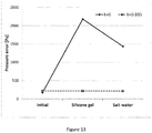
- Figure 13 illustrates results of the experiment phases of the figures 9 , 10 and 11 .
- Two sets of results of pressure error in the readings received from the sensor are shown.
- the pressure error in the initial phase illustrated with the figure 10 has no significant difference between the uncompensated result and the compensated result.
- the uncompensated pressure error due to change in the interconnection capacitances would be 2200 Pa, and after exposing the molded circuitry to salt water, the uncompensated pressure error would be in the level of 1500 Pa, whereas the in the compensated readings the pressure error remains essentially the same independent on whether filling and salt water were disposed or not.
- the reason for decrease of the pressure error and thus the measured capacitance in the third phase with the salt water added was that the electrically conductive salt water on top of the mold material added shielding ground potential around the interconnections and thus decreased the interconnection capacitances.
- the initial pressure error and all the compensated pressure errors in Figure 13 are all about +200 Pa. This error is the smallest that may be obtained around the atmospheric pressure with the chosen calibration function P, which was a hyperbolic function of first order with three independent calibration coefficients.
Abstract
Description
- The present invention relates to a method related to capacitive sensors. More particularly, the invention relates to a method for canceling interconnection capacitance of a capacitive sensor caused by environmental conditions and an apparatus configured to perform such method.
- The term capacitive sensor refers to a sensor configured to detect various physical quantities. The measured physical quantity causes a change in a capacitance of the sensor, which can be detected with electronic circuitry and converted for example into digital data. Examples of capacitive sensors are for example capacitive pressure sensors, accelerometers, humidity sensors and chemical sensors.
- In capacitive sensor devices an interconnection from a circuitry performing analysis of capacitance values provided by the sensor circuitry often introduces an additional parallel capacitance, which may depend on environmental conditions like temperature and humidity. This interconnection capacitance may cause significant error in the detected capacitance value, and thus error in the detection of the physical quantity measured by the capacitive sensor. Many commonly used dielectric materials are quite unstable with respect to change in environmental conditions. For example, silicone gel that gives excellent protection from fluids in the environment absorbs quite a lot of moisture, which will change the silicone gel's relative permittivity. Relative permittivity of a material is expressed by its dielectric constant. Thus, a change of the relative permittivity is indicated by a change of the dielectric constant. In some materials, like the exemplary silicone gel, the effect of moisture absorbance and the caused change of dielectric constant is quite rapid, varying from minutes to hours. In other materials the change of dielectric constant may be much slower. The change in environmental conditions will change the apparent total sensor capacitance and this change is impossible to distinguish from the change of the physical quantity the sensor is supposed to measure, such as atmospheric pressure or blood pressure.
- It is obvious that if the interconnection capacitance could be measured separately it could be subtracted from the total sensor capacitance and the accuracy of the sensor readings could be maintained. Unfortunately, it is not possible to measure the exact value of a particular interconnection disposed inside a structure without disconnecting the sensor from the interconnection and re-connecting it again, which is too tedious in practice and involves possibility to additional changes of the interconnection capacitance.
- In related art the interconnection capacitance is often minimized by special shielding arrangements.
- International patent application
WO 2014/195878 discloses a shielding method that could be used for shielding also the interconnection wiring tracks on a substrate. In this method, shielding requires multiple conductor and dielectric layers that may not be applicable in assemblies that require very small thickness and very high flexibility. - An object is to provide a method and an apparatus so as to solve the problem of canceling changes in interconnection capacitance between a capacitive sensor and an interface circuitry due to changes of the relative permittivity without special shield layers. The objects of the present invention are achieved with a method according to the characterizing portion of claim 1. The objects of the present invention are further achieved with an apparatus according to the characterizing portion of
claim 11. - The preferred embodiments of the invention are disclosed in the dependent claims.
- The present invention is based on the idea of introducing a compensating interconnection that enables fully compensating the amount of change of interconnection capacitance in a sensor interconnection due to changes of relative permittivity in its environment. A compensating interconnection capacitance value is obtained, and a weight coefficient is determined that is used to multiply the compensating interconnection capacitance value before subtracting the multiplied compensating interconnection capacitance value from an obtained total sensor capacitance value in order to receive a compensated sensor capacitance value.
- The present invention has the advantage that it enables essentially removing any sensor interconnection capacitance caused error from an output signal of a capacitive sensor. Accuracy of sensing results achieved with the capacitive sensor is thus improved.
- According to a first aspect, a method for cancelling effects of changes in interconnection capacitances on capacitive sensor readings provided by a capacitive sensor is provided. The capacitive sensor is connected with an interface circuitry with at least two interconnections comprising a sensor interconnection and a compensating interconnection.
- The method comprises obtaining a total sensor capacitance value from the capacitive sensor, obtaining a total compensating interconnection capacitance value from the compensating interconnection, calculating a compensated sensor capacitance value by reducing the obtained total compensating interconnection capacitance value multiplied with a weight coefficient from the obtained total sensor capacitance value, and providing an electrical signal at an output of the interface circuitry that corresponds to the compensated sensor capacitance value. The compensated sensor capacitance value is independent of changes of relative permittivity in the immediate environment of the capacitive sensor, the interface circuitry and the interconnections thereof.
- According to a second aspect, the method further comprises connecting the interface circuitry to the compensating interconnection disposed at the immediate vicinity of the sensor interconnection for obtaining the total compensating interconnection capacitance value. The compensating interconnection is electrically connected only to the interface circuitry.
- According to a third aspect, the method further comprises obtaining, by the interface circuitry, the total sensor capacitance value when the sensor interconnection is coupled at its first input and a common interconnection is coupled at its second input, and obtaining, by the interface circuitry, the total compensating interconnection capacitance value when the compensating interconnection is coupled at its first input and the common interconnection is coupled at its second input.
- According to a fourth aspect, the method further comprises multiplexing the first input of the interface circuitry to be connected to one of the sensor interconnection for obtaining the total sensor interconnection capacitance value, and the compensating interconnection for obtaining the total compensating interconnection capacitance value. The multiplexing occurs at a frequency in a range between 10 milliseconds and 10 minutes.
- According to a fifth aspect, the method further comprises obtaining, by the interface circuitry, an integrating base capacitance value when only an integrating base capacitance is coupled at its first input and a common interconnection is coupled at its second input, obtaining, by the interface circuitry, the total sensor capacitance value when the sensor interconnection is coupled at its first input and the common interconnection is coupled at its second input, wherein the total sensor capacitance value includes the integrating base capacitance value, and obtaining, by the interface circuitry, the total compensating interconnection capacitance value when the compensating interconnection is coupled at its first input and the common interconnection is coupled at its second input, wherein the total compensating interconnection capacitance value includes the integrating base capacitance value. The method further comprises subtracting the integrating base capacitance value from both the total sensor interconnection capacitance value and the total compensating interconnection capacitance value before calculating the compensated sensor capacitance.
- According to a sixth aspect, the method further comprises multiplexing the first input of the interface circuitry to be connected to one of the sensor interconnection for obtaining the total sensor interconnection capacitance value, the compensating interconnection for obtaining the total compensating interconnection capacitance value, and the integrating base capacitance for obtaining the integrating base capacitance value. The multiplexing occurs at a frequency in a range between 10 milliseconds and 10 minutes.
- According to a seventh aspect, the method further comprises disposing the compensating interconnection so that a capacitance between the compensating interconnection and the common interconnection is essentially equal to a capacitance between the sensor interconnection and the common interconnection.
- According to an eighth aspect, the method comprises obtaining the weight coefficient by steps of measuring a first total sensor capacitance value and a first total compensating interconnection capacitance value in a first measurement, subjecting the capacitive sensor and its interconnections to a change of relative permittivity in their immediate environment, measuring a second total sensor capacitance value and a second total compensating interconnection capacitance value in a second measurement after subjecting the capacitive sensor and its interconnections to the change of relative permittivity in their immediate environment, calculating a change of the measured total sensor capacitance based on the change between the first and the second total sensor capacitance values, and a change of the measured compensating interconnection capacitance based on the change between the first and the second total compensating interconnection capacitance values; and calculating the weight coefficient by dividing the change of the measured total sensor capacitance by the change of the measured compensating interconnection capacitance.
- According to a ninth aspect, the method comprises obtaining the weight coefficient by steps of defining a calibration function, measuring a first total sensor capacitance value, a first total compensating capacitance value and a first reference pressure value, calculating a first compensated sensor capacitance value based on the first total sensor capacitance value and the first total compensating capacitance value using a dummy weight coefficient, calculating, using the calibration function, a first pressure value corresponding to the first compensated sensor capacitance value, subjecting the capacitive sensor and its interconnections to a change of relative permittivity in their immediate environment, measuring a second total sensor capacitance value, a second total compensating capacitance value and a second reference pressure value after subjecting the capacitive sensor and its interconnections to the change of relative permittivity in their immediate environment, calculating a second compensated sensor capacitance value based on the second total sensor capacitance value and the second total compensating capacitance value, calculating, using the calibration function, a second pressure value based on the second compensated sensor capacitance value; and obtaining the weight coefficient by adjusting the weight coefficient used for calculating the first compensated sensor capacitance value, the second compensated sensor capacitance value, the first pressure value and the second pressure value so that a first pressure error calculated using the adjusted weight coefficient equals with a second pressure error calculated using the same adjusted weight coefficient, wherein the first pressure error equals the difference between the first pressure value and the first reference pressure value and the second pressure error equals the difference between the second pressure value and the second reference pressure value.
- According to a first device aspect, an apparatus configured to cancel effects of changes in interconnection capacitances on capacitive sensor readings is provided. The apparatus comprises at least the capacitive sensor and an interface circuitry. The capacitive sensor is connected to the interface circuitry with at least two interconnections comprising a sensor interconnection and a compensating interconnection. The apparatus is configured to obtain a total sensor capacitance value from the capacitive sensor, obtain a total compensating interconnection capacitance value from the compensating interconnection, calculate a compensated sensor capacitance value by reducing the obtained total compensating interconnection capacitance value multiplied with a weight coefficient from the obtained total sensor capacitance value, and provide at its output an electrical signal corresponding to the compensated sensor capacitance value. The compensated sensor capacitance value is independent of changes of relative permittivity in the immediate environment of the capacitive sensor, the interface circuitry and the interconnections thereof.
- According to a second device aspect the compensating interconnection is disposed at the immediate vicinity of the sensor interconnection. The interface circuitry is configured to be connected to the compensating interconnection for obtaining the total compensating interconnection capacitance value. The compensating interconnection is electrically connected only to the interface circuitry.
- According to a third device aspect a common interconnection is coupled at a second input of the interface circuitry. The apparatus further comprises a switch configured to multiplex a first input of the interface circuitry to be connected to one of the sensor interconnection for obtaining the total sensor interconnection capacitance value, and the compensating interconnection for obtaining the total compensating interconnection capacitance value. The multiplexing occurs at a frequency in a range between 10 milliseconds and 10 minutes.
- According to a fourth device aspect a common interconnection is coupled at a second input of the interface circuitry. The apparatus further comprises a switch configured to multiplex a first input of the interface circuitry to be connected to one of only an integrating base capacitance for obtaining an integrating base capacitance value, the sensor interconnection for obtaining the total sensor interconnection capacitance value that includes the integrating base capacitance value and the compensating interconnection for obtaining the total compensating interconnection capacitance value that includes the integrating base capacitance value. The multiplexing occurs at a frequency in a range between 10 milliseconds and 10 minutes. The apparatus is further configured to subtract the integrating base capacitance value from both the total sensor interconnection capacitance value and the total compensating interconnection capacitance value before calculating the compensated sensor capacitance.
- According to a fifth apparatus aspect, the compensating interconnection is disposed so that a capacitance between the compensating interconnection and the common interconnection is essentially equal to a capacitance between the sensor interconnection and the common interconnection.
- According to a sixth apparatus aspect, the apparatus is further configured to measure a first total sensor capacitance value and a first total compensating interconnection capacitance value in a first measurement, to measure a second total sensor capacitance value and a second total compensating interconnection capacitance value in a second measurement after the capacitive sensor and its interconnections have been subjected to a change of relative permittivity in their immediate environment, to calculate a change of the measured total sensor capacitance based on the change between the first and the second total sensor capacitance values, to calculated a change of the measured compensating interconnection capacitance based on the change between the first and the second total compensating interconnection capacitance values, and to calculate the weight coefficient by dividing the change of the measured total sensor capacitance by the change of the measured compensating interconnection capacitance.
- According to a seventh apparatus aspect, the apparatus is further configured to define a calibration function, to measure a first total sensor capacitance value, a first total compensating capacitance value and a first reference pressure value, to calculate a first compensated sensor capacitance value based on the first total sensor capacitance value and the first total compensating capacitance value using a dummy weight coefficient, to calculate, using a calibration function, a first pressure value corresponding to the first compensated sensor capacitance value, to measure a second total sensor capacitance value, a second total compensating capacitance value and a second reference pressure value after the capacitive sensor and its interconnections have been subjected to a change of relative permittivity in their immediate environment, to calculate a second compensated sensor capacitance value based on the second total sensor capacitance value and the second total compensating capacitance value and to calculate, using the calibration function, a second pressure value based on the second compensated sensor capacitance value, and to obtain the weight coefficient by adjusting the weight coefficient used for calculating the first compensated sensor capacitance value, the second compensated sensor capacitance value, the first pressure value and the second pressure value so that a first pressure error calculated using the adjusted weight coefficient equals with a second pressure error calculated using the same adjusted weight coefficient, wherein the first pressure error equals the difference between the first pressure value and the first reference pressure value and the second pressure error equals the difference between the second pressure value and the second reference pressure value.
- In the following the invention will be described in greater detail, in connection with preferred embodiments, with reference to the attached drawings, in which
-
Figure 1 illustrates a flow chart of a first process for defining a weight coefficient. -
Figure 2 illustrates a flow chart of a second process for defining a weight coefficient. -
Figure 3 illustrates a schematic of a circuitry. -
Figure 4 illustrates a schematic of an exemplary implementation of a circuitry. -
Figure 5 illustrates a flow chart of the process for calculating the compensated sensor capacitance. -
Figure 6 illustrates a first cross-section of the medical catheter device. -
Figure 7 illustrates a second cross-section of the medical catheter device. -
Figure 8 illustrates interconnections between adjacent ends of a sensor chip and an interface circuitry chip according to a first embodiment. -
Figure 9 illustrates a top view of an interface circuitry chip and a capacitive sensor chip and the interconnections thereof according to a second embodiment. -
Figure 10 illustrates a first phase of an experiment. -
Figure 11 illustrates a second phase of an experiment. -
Figure 12 illustrates a third phase of an experiment. -
Figure 13 illustrates results of an experiment. - The term circuitry refers to any electronic device capable of receiving, producing or processing electrical signals.
- A sensor interconnection couples a sensor to an electronic circuitry. The electronic circuity may be configured at least to process sensor signals, also known as sensor readings received from the sensor. This invention assumes that there is an additional compensating interconnection that can be interchanged with the sensor interconnection at an electronic circuitry that has a multiplexed input. The compensating interconnection may also be called a dummy interconnection, since it does not actually interconnect any electronic circuitries. The other end of this compensating interconnection is not connected to anything and it should be dimensioned as similar to the sensor interconnection as possible and also disposed into a position as similar to the sensor interconnection as possible. Multiplexing the input allows measuring a capacitance value of the compensating interconnection. This compensating interconnection capacitance can't, however, be subtracted as such from the total detected sensor capacitance value, since in a practical design and implementation taking the production tolerances into account the compensating interconnection can never exactly duplicate the sensor interconnection.
- According to this invention it is possible to find a constant weight coefficient for multiplying the compensating interconnection capacitance before subtracting it from the detected total sensor capacitance. The invention is based on using a mold material to fill empty surfaces and spaces near the sensor, circuit and interconnections. The mold material may also be called filling material. The mold material preferably has a dielectric constant εr greater than 1, which is the dielectric constant of air. Molding will change the sensor interconnection capacitance and thus the detected total sensor capacitance C Stot and the detected compensating interconnection capacitance C Ctot. If the change of the total detected sensor capacitance is ΔCS and the change of the compensating interconnection capacitance is ΔCC then the right weight coefficient k to use is


- The compensated sensor capacitance C Scomp thus obtained is essentially free of the influence of the dielectric constant εr of the mold material and, if the interconnections are properly designed, also any other interconnection capacitance components that are not due to the mold material are cancelled. Equivalent alternative and often the easiest way to obtain the right weight coefficient is to calibrate the sensor first using a dummy weight coefficient value k=0 or k=1 or any guessed value for k and select then a new k so that the sensor shows the same pressure error with respect to the prevailing pressure before and after molding.
- In the following description, the method for cancelling the interconnection capacitance is proven mathematically.
- The total sensor capacitance C Stot can be defined as a combination of three components: the sensor capacitance Cs, the interconnection capacitance due to the mold cavity CSM and interconnection capacitance due to other materials Cso. Correspondingly, the compensating interconnection capacitance C Ctot may be defined as a combination of two components: the interconnection capacitance due to the mold cavity CCM and due to other materials CCO .


- Combining equations (5) and (6) gives the physical meaning of the weight coefficient k of equation (1):

- The equation for the compensated sensor capacitance (2) now becomes

- If the compensating interconnection is designed very similar to the sensor interconnection, then


-
Figure 1 illustrates a flow chart of a first exemplary process for defining the weight coefficient k. In thephase 10, the total sensor capacitance is measured, and in thephase 11 the total compensating interconnection capacitance is measured. As understood by a skilled person, phases 10 and 11 may be performed in any order without departing from the scope. After obtaining the initial values of the total sensor interconnection capacitance and the total compensating interconnection capacitance, the interconnections are covered in thephase 12 with a mold having a dielectric constant εr higher than that of the air. The molding causes subjecting the sensor and its interconnections to a change of the relative permittivity and thus also a change of the dielectric constant in their immediate environment. As known in the art, change of the relative permittivity of material between plates of a capacitor causes a change of capacitance. - After applying the mold material in the
phase 12, the total sensor capacitance is measured again in thephase 14 and the total compensating interconnection capacitance is measures again in thephase 15. Similar tophases phases -
Figure 2 illustrates a flow chart of a second exemplary process for defining the weight coefficient k. In the second process, the mathematical basis for defining the weight coefficient k is the same as in the first exemplary process, but this method allows change in the ambient pressure during the definition process and is thus more feasible to be used in a manufacturing and calibration process of a commercial product. - A calibration function P is defined for calibrating the pressure sensor in the
phase 20. In order to define the calibration function, the total sensor capacitance and the total interconnection capacitance are measured at a number of pressure points and the capacitance and pressure values are recorded. The pressure values at the number of pressure points may be recorded with a second, calibrated pressure sensor. A mathematical calibration function P is defined for calculating the output pressure value from the compensated sensor capacitance value. The calibration function P is a function that gives the smallest average pressure error over the desired pressure range. The function may be a polynomial of capacitance values or inverse capacitance values or it may be a hyperbolic function of the capacitance value (i.e. a sum of a constant and an inverse of a polynomial of capacitance values) or it may be based on a look-up table with interpolated values between the tabulated values. The numerical constants in this function or the tabulated values are called calibration coefficients. The calibration function P is a function of the compensated sensor capacitance C Scomp and the weight coefficient k, and the result of the calibration function P is a pressure value p. A dummy weight coefficient k0 is used in thecalibration phase 20. For example, the dummy weight coefficient k0 may be given a value k0=0, k0=1 or any other value e.g. based on experience on prior, nominally similar devices. The calibration function may be performed by any known type of processing device, for example a computer, a processor, a microprocessor, an application specific integrated circuit (ASIC) and so on. - In the
phase 21, the total sensor capacitance CStot and the total compensating interconnection capacitance CCtot are measured. Preferably, the total sensor capacitance value is measured simultaneously with the measurement of a first reference pressure value with the reference pressure sensor in the phase 21' illustrated by the dashed box in the flow chart. - Based on the obtained capacitance values in the
phase 21, a first compensated sensor capacitance C Scomp1 is calculated in thephase 22 using the equation (2) with the dummy weight coefficient k0 used during thecalibration phase 20. - A first detected pressure value p is calculated in the
phase 23 with the calibration function P using the first compensated sensor capacitance C Scomp1 and the dummy weight coefficient k0. The first pressure value p after the first measurement may thus be expressed by the equation
- If the calibration coefficients were selected optimally in the
calibration phase 20 then equation (12) for a first pressure error Perr1 is at least approximately true:
- Although not shown in the
figure 2 , the first pressure error may be calculated at any phase after obtaining the first pressure value and the first reference pressure value for example for verifying the calibration function. The pressure and capacitance measurements of thephases 21 and 21' occur preferably essentially simultaneously, and the reference pressure sensor should be located near the sensor under calibration so that the ambient pressure is essentially the same for the both sensors. The first pressure error Perr1 may also be calculated only during the phase 29. - The sensor is then molded in the
phase 24, covering the sensor with the protective filling, and thus subjecting the sensor and its interconnections to a change of relative permittivity and the dielectric constant in their immediate environment. After the molding in thephase 24, the total sensor capacitance CStot and the total compensating capacitance CCtot are measured again in thephase 25, and a second compensated sensor capacitance C Scomp2 is calculated in thephase 26 using the equation (2). - The ambient pressure may have changed to p2, since some time has passed since the first pressure measurement used for the calibration, and also because it may not be economically feasible to standardize the ambient pressure. The ambient pressure p2 is measured with the reference pressure sensor in the phase 25' preferably essentially simultaneously to measuring the total sensor capacitance and the total compensating capacitance in the
phase 25 as illustrated with the dashed box in the flow chart. Preferably, the total sensor capacitance value is measured simultaneously with the measurement of the reference pressure value with the reference pressure sensor. Although not shown in thefigure 2 , the first pressure error may be calculated at any phase after obtaining the second pressure value and the second reference pressure value for example for verifying the calibration function. - The dielectric constant of the filling material has now altered the total sensor capacitance and using the dummy weight coefficient k0 perfect compensation of the capacitance will not occur. A second pressure error calculated with equation (12) would therefore now be non-zero:

- In order to cancel the effect of the mold material it is desired to equalize the pressure errors before and after filling with the mold material. An adjusted weight coefficient k may now be defined in the
phase 27 using the calibration function P, so that that the pressure readings provided by the pressure sensor fulfill the condition for the pressure measurement error:
- In other words, the weight coefficient k is adjusted so that the newly calculated first pressure error Perr1 equals with the second pressure error Perr2 both being calculated with the adjusted weight coefficient k.
- Using the adjusted coefficient k, the equation (12) holds no more and the non-zero pressure error Perr1 = Perr2 of equation (13) may become significant. But it is more important to ensure that the change in the compensated sensor capacitance due to the dielectric constant of the added mold material is zero. This target can be achieved by defining the correct value of the weight coefficient k used in the calibration function P for calculating the compensated sensor capacitance.
- In the
optional phase 28 the calibration function may be further updated using the original recorded calibration data points fromphase 20 with the adjusted weight coefficient k defined in thephase 27. The updated calibration function Pupd is a function that gives the smallest average pressure error over the desired pressure range when using the adjusted weight coefficient k. Correctness of the updated calibration function Pupd may be checked by the required condition
- In other words, if the updated calibration function Pupd is defined correctly, the difference between the first and the second obtained pressure values calculated from the first and second compensated sensor capacitances using the updated calibration function Pupd and the weight coefficient k, and the respective first and second ambient pressures p1 and p2, becomes approximately zero. The updated calibration function Pupd now includes both the information on the correct adjusted weight coefficient k and any other calibration parameters needed to obtain accurate pressure value readings. The updated calibration function Pupd and the adjusted weight coefficient k may be applied to obtain a compensated and calibrated pressure value based on a total sensor capacitance value and a total interconnection capacitance value received from the pressure sensor and the dummy interconnection.
-
Figure 3 illustrates a general schematic of a circuitry used for implementation of the above described compensating method. Aninterface circuitry 100 comprises at least capacitance conversion unit configured to convert the capacitance value of a capacitor connected to it into an analog ordigital output signal 110. Theoutput signal 110 may be characterized as an electrical signal representing a value of a physical quantity. In case of a capacitive sensor, the output signal may be an analog or digital signal corresponding to or representing an obtained capacitance value. Aswitching unit 101 enables to connect either the total sensor capacitance C Stot or the total compensating interconnection capacitance C Ctot to the input of the capacitance conversion unit. Multiplexing, in other words switching between the two capacitances, should be done often enough depending on the speed of the changes of the dielectric constant in their environment. In some cases, the frequency maybe once in ten minutes and in other cases every millisecond. - There are three types of interconnections in this arrangement. A
sensor interconnection 111 is coupled to one multiplexed input of theswitching unit 101, and it connects the sensor to capacitance conversion unit of theinterface circuitry 100 via theswitching unit 101. A compensatinginterconnection 113 is coupled to the other multiplexed input of theswitching unit 101. Acommon interconnection 112 is preferably directly coupled to an input of the capacitance conversion unit of theinterface circuitry 100. - Instead of the circuitry of the
figure 3 , any other circuitry may be used to implement the functionalities of thefigures 1 and2 . -
Figure 4 illustrates a schematic of an exemplary implementation of a circuitry comprising a combined conversion unit and a switching unit. This implementation comprises of an integrating converter where a constant current I is fed from acurrent source 210 to the inverting input of an amplifier 220 and an integrating base capacitance is provided between the inverting input (-) and output of the amplifier 220. In the circuitry of thefigure 4 , the output voltage provided at theoutput 110 will rise with a constant slope that is proportional to the integrating base capacitance. This slope may be measured with two threshold voltage level detectors and a pulse counter (not shown). The integrating base capacitance is a sum of abase capacitance 225 and either the total sensor capacitance C Stot or the total compensating interconnection capacitance C Ctot, depending on the position of theswitch 101. Thebase capacitance 225 is needed since the value of the total compensating interconnection capacitance C Ctot may be very small and the slope of the output voltage may be very steep which may lead to an impractically short time period between two output voltage threshold levels. The known value of thebase capacitance 225 is be subtracted from the total sensor capacitance C Stot and the total compensating interconnection capacitance C Ctot before applying equation (2). This is easily implemented by having a third position of theswitch 101 with which only thebase capacitance 225 switched to the converter. -
Figure 5 illustrates a flow chart of the process for calculating a compensated sensor capacitance. - In the
phase 41, the switching circuit is changed to couple with the interconnection towards the base capacitance, and the base capacitance is measured. This phase is needed only if a base capacitance is used as illustrated in thefigure 4 . If there is no base capacitance to be measured, thephase 41 may be omitted. In thephase 42, the switching circuit is changed to couple with the sensor interconnection, and the total sensor capacitance is measured. In thephase 43, the switching circuit is changed to couple with the compensating interconnection, and the total compensating interconnection capacitance is measured. If a base capacitance was measured in thephase 41, the base capacitance value is first subtracted from both the total sensor interconnection capacitance value and the total compensating interconnection capacitance value, and then the compensated sensor capacitance is calculated using the equation (2) in thecalculation phase 44. If no base capacitance was measured, the compensated sensor capacitance may be calculated directly based in the measured total sensor capacitance and the total compensating interconnection capacitance. Thesteps phases -
Figures 5 ,6 and 7 illustrate a first exemplary embodiment of the invention. This embodiment discloses a structure of a medical catheter device where theinterface circuitry 100 and thecapacitive sensor 70 are implemented by semiconductor chips which are flip-chipped on aflexible circuit board 50. As known by a person skilled in the art, the term flip-chipped refers a semiconductor mounting technology in which a bare semiconductor chip with solder bumps or other equivalent protruding members disposed on chip pads of the semiconductor chip may be directly coupled to an external circuit by reflow soldering, conductive adhesive or equivalent. -
Figures 5 and6 illustrate a cross-section of the medical catheter device. This cross-section may equally represent either the installation of thecapacitive sensor chip 70 or theinterface circuitry 100. Both the flip-chippedinterface circuitry 100 and the flip-chippedcapacitive sensor 170 are coupled by the solder bumps 53 withwiring 54 exposed on the face of theflexible circuit board 50. Theflexible circuit board 50 is wrapped around amedical catheter body 51 so that both theinterface circuitry 100 and thecapacitive sensor 170 are disposed in arecess 52 manufactured within the side wall of thehollow catheter body 51. - For defining of the calibration coefficient k, the initially air-filled
installation recess 52 shown in thefigure 6 is filled withmold material 152 as illustrated in thefigure 7 . Themold material 152 may be for example silicone gel. Theinstallation recess 52 represents the immediate environment of the circuitry and the interconnections thereof. -
Figure 8 illustrates interconnections between adjacent ends of thesensor chip 170 and theinterface circuitry chip 100. Thechip pads 70 are coupled with wiring on the flexible circuit board by the solder bumps 53. Interconnection tracks 111, 112 are disposed on theflexible circuit board 50 that electrically connect thesensor 170 and theinterface circuitry 100 with each other. The compensatinginterconnection track 113 is only connected to an input of theinterface circuitry 100 and it follows thesensor interconnection track 111 disposed between thesensor 170 and theinterconnection circuitry 100 as closely as possible in the immediate vicinity of thesensor interconnection track 111. The aim of the placement of the tracks is to have an equal capacitance from both thesensor interconnection track 111 and the compensatinginterconnection track 113 to thecommon interconnection track 112. The equal capacitances facilitate obtaining an accurate weight coefficient k. -
Figures 9 ,10, 11 and 12 illustrate a second exemplary embodiment of the invention. The second embodiment is particularly useful for verifying the validity of the compensation method. -
Figure 9 illustrates a top view of theinterface circuitry chip 100 and thecapacitive sensor chip 170 and the interconnections thereof according to the second embodiment. Now thechip pads 70 are interconnected with bond wires. A floatingbond pad 80 is provided that allows placement of the compensatinginterconnection bond wire 113. The term floating bond pad refers to a pad allowing mechanical action of bonding, but which does not provide an electrical connection. In addition to the sensorinterconnection bond wire 111 and the commoninterconnection bond wire 112, additional bond wires may be disposed. In this example, there is a groundinterconnection bond wire 114. The compensatinginterconnection bond wire 113 is disposed so that the capacitance between the compensatinginterconnection bond wire 113 and the commoninterconnection bond wire 112 is as close to the capacitance between the sensorinterconnection bond wire 111 and the commoninterconnection bond wire 112 as possible. -
Figures 10, 11 and 12 illustrate a cross-section of the second embodiment, in which the circuitry is disposed in aceramic housing 90. The ceramic housing has alower cavity 92 into which theinterface circuitry 100, thesensor 170, theinterconnection bond wires bond pad 80 are disposed. This cross-section only shows the sensorinterconnection bond wire 111 and the compensatinginterconnection bond wire 113. This embodiment also has anupper cavity 91, which is optional. Theupper cavity 91 may be used for experimenting the effectiveness of the compensation method, but is not required for a commercial product. Thelower cavity 92 or the combination of thelower cavity 92 and theupper cavity 91 represent the immediate environment of the circuitry disposed in the cavity and the interconnections thereof. - In the
figure 10 , thebare chips lower cavity 92 and bonded withbond wires sensor 170 may be calibrated for accurate pressure readings. - The
figure 11 illustrates a second phase of the experiment, in which thelower cavity 92 was filled withmold material 152. This mold material may be for example silicone gel with a dielectric constant different from that of the air. The capacitance changes due to gel molding are measured and the value of the weight coefficient k may now be calculated based on the capacitance measurements. - In the experiments performed, the calculated weight coefficient received a value k=0.835. As expected, the weight coefficient value was smaller than 1, since the compensating interconnecting
bond wire 113 is longer than the sensor interconnectingbond wire 111 and is closer to the common interconnection bond wire and therefore the interconnection capacitance of the compensating interconnecting bond wire is greater than the sensor interconnection capacitance due to the sensor interconnecting bond wire. - The
figure 12 illustrates a third phase of the experiment, in which theupper cavity 91 was filled withsalt water solution 93. While the experiment was intended to mimic environment in which the catheter of the first embodiment would be utilized, a 1% solution of salt and water was used to mimic bodily fluids. After a while, the capacitances between the interconnections were measured again. -
Figure 13 illustrates results of the experiment phases of thefigures 9 ,10 and 11 . Two sets of results of pressure error in the readings received from the sensor are shown. A first set of results, marked with diamonds interconnected with a solid line illustrate pressure error without compensation, in other words with a weight coefficient k=0. We may call this result set as the uncompensated result set. A second set of results, marked with squares interconnected with a dashed line, illustrates pressure error with compensating, using the obtained weight coefficient k=0.835. We may call this result set as the compensated result set. - The pressure error in the initial phase illustrated with the
figure 10 has no significant difference between the uncompensated result and the compensated result. After applying themold material 152, the uncompensated pressure error due to change in the interconnection capacitances would be 2200 Pa, and after exposing the molded circuitry to salt water, the uncompensated pressure error would be in the level of 1500 Pa, whereas the in the compensated readings the pressure error remains essentially the same independent on whether filling and salt water were disposed or not. The reason for decrease of the pressure error and thus the measured capacitance in the third phase with the salt water added was that the electrically conductive salt water on top of the mold material added shielding ground potential around the interconnections and thus decreased the interconnection capacitances. The initial pressure error and all the compensated pressure errors inFigure 13 are all about +200 Pa. This error is the smallest that may be obtained around the atmospheric pressure with the chosen calibration function P, which was a hyperbolic function of first order with three independent calibration coefficients. - The experiment illustrated in the
figures 9 to 13 proofed effectiveness of the invented compensation method. - It is apparent to a person skilled in the art that as technology advanced, the basic idea of the invention can be implemented in various ways. The invention and its embodiments are therefore not restricted to the above examples, but they may vary within the scope of the claims.
Claims (16)
- A method for cancelling effects of changes in interconnection capacitances on capacitive sensor readings provided by a capacitive sensor connected with an interface circuitry with at least two interconnections comprising a sensor interconnection and a compensating interconnection, the method comprising:- obtaining a total sensor capacitance value from the capacitive sensor;- obtaining a total compensating interconnection capacitance value from the compensating interconnection;- calculating a compensated sensor capacitance value by reducing the obtained total compensating interconnection capacitance value multiplied with a weight coefficient from the obtained total sensor capacitance value; and- providing an electrical signal at an output of the interface circuitry that corresponds to the compensated sensor capacitance value, characterized in that the compensated sensor capacitance value is independent of changes of relative permittivity in the immediate environment of the capacitive sensor, the interface circuitry and the interconnections thereof.
- The method according to claim 1, further comprising:- connecting the interface circuitry to the compensating interconnection disposed at the immediate vicinity of the sensor interconnection for obtaining the total compensating interconnection capacitance value, wherein the compensating interconnection is electrically connected only to the interface circuitry.
- The method according to claim 2, further comprising:- obtaining, by the interface circuitry, the total sensor capacitance value when the sensor interconnection is coupled at its first input and a common interconnection is coupled at its second input; and- obtaining, by the interface circuitry, the total compensating interconnection capacitance value when the compensating interconnection is coupled at its first input and the common interconnection is coupled at its second input.
- The method according to claim 3, further comprising:- multiplexing the first input of the interface circuitry to be connected to one of:wherein the multiplexing occurs at a frequency in a range between 10 milliseconds and 10 minutes.- the sensor interconnection for obtaining the total sensor interconnection capacitance value; and- the compensating interconnection for obtaining the total compensating interconnection capacitance value;
- The method according to claim 2, further comprising:- obtaining, by the interface circuitry, an integrating base capacitance value when only an integrating base capacitance is coupled at its first input and a common interconnection is coupled at its second input;- obtaining, by the interface circuitry, the total sensor capacitance value when the sensor interconnection is coupled at its first input and the common interconnection is coupled at its second input, wherein the total sensor capacitance value includes the integrating base capacitance value;- obtaining, by the interface circuitry, the total compensating interconnection capacitance value when the compensating interconnection is coupled at its first input and the common interconnection is coupled at its second input, wherein the total compensating interconnection capacitance value includes the integrating base capacitance value; and- subtracting the integrating base capacitance value from both the total sensor interconnection capacitance value and the total compensating interconnection capacitance value before calculating the compensated sensor capacitance.
- The method according to claim 5, further comprising:- multiplexing the first input of the interface circuitry to be connected to one of:wherein the multiplexing occurs at a frequency in a range between 10 milliseconds and 10 minutes.- the sensor interconnection for obtaining the total sensor interconnection capacitance value,- the compensating interconnection for obtaining the total compensating interconnection capacitance value, and- the integrating base capacitance for obtaining the integrating base capacitance value,
- The method according to any of claims 2 to 6, further comprising:- disposing the compensating interconnection so that a capacitance between the compensating interconnection and the common interconnection is essentially equal to a capacitance between the sensor interconnection and the common interconnection.
- The method according to any of claims 2 to 7, wherein the method comprises obtaining the weight coefficient by steps of:- measuring a first total sensor capacitance value and a first total compensating interconnection capacitance value in a first measurement;- subjecting the capacitive sensor and its interconnections to a change of relative permittivity in their immediate environment;- measuring a second total sensor capacitance value and a second total compensating interconnection capacitance value in a second measurement after subjecting the capacitive sensor and its interconnections to the change of the relative permittivity in their immediate environment;- calculating a change of the measured total sensor capacitance based on the change between the first and the second total sensor capacitance values, and a change of the measured compensating interconnection capacitance based on the change between the first and the second total compensating interconnection capacitance values; and- calculating the weight coefficient by dividing the change of the measured total sensor capacitance by the change of the measured compensating interconnection capacitance.
- The method according to any of claims 1 to 8, wherein the method comprises obtaining the weight coefficient by steps of:- defining a calibration function;- measuring a first total sensor capacitance value, a first total compensating capacitance value and a first reference pressure value;- calculating a first compensated sensor capacitance value based on the first total sensor capacitance value and the first total compensating capacitance value using a dummy weight coefficient;- calculating, using the calibration function, a first pressure value corresponding to the first compensated sensor capacitance value;- subjecting the capacitive sensor and its interconnections to a change of the relative permittivity in their immediate environment;- measuring a second total sensor capacitance value, a second total compensating capacitance value and a second reference pressure value after subjecting the capacitive sensor and its interconnections to the change of the relative permittivity in their immediate environment;- calculating a second compensated sensor capacitance value based on the second total sensor capacitance value and the second total compensating capacitance value;- calculating, using the calibration function, a second pressure value based on the second compensated sensor capacitance value; and- obtaining the weight coefficient by adjusting the weight coefficient used for calculating the first compensated sensor capacitance value, the second compensated sensor capacitance value, the first pressure value and the second pressure value so that a first pressure error calculated using the adjusted weight coefficient equals with a second pressure error calculated using the same adjusted weight coefficient, wherein the first pressure error equals the difference between the first pressure value calculated using the adjusted weight coefficient and the first reference pressure value and the second pressure error equals the difference between the second pressure value calculated using the adjusted weight coefficient and the second reference pressure value.
- An apparatus configured to cancel effects of changes in interconnection capacitances on capacitive sensor readings, the apparatus comprising a capacitive sensor and an interface circuitry, wherein the capacitive sensor is connected to the interface circuitry with at least two interconnections comprising a sensor interconnection and a compensating interconnection, and wherein the apparatus is configured to:- obtain a total sensor capacitance value from the capacitive sensor;- obtain a total compensating interconnection capacitance value from the compensating interconnection;- calculate a compensated sensor capacitance value by reducing the obtained total compensating interconnection capacitance value multiplied with a weight coefficient from the obtained total sensor capacitance value; and- provide at its output an electrical signal corresponding to the compensated sensor capacitance value, characterized in that the compensated sensor capacitance value is independent of changes of relative permittivity of the immediate environment of the capacitive sensor, the interface circuitry and the interconnections thereof.
- The apparatus according to claim 10, wherein the compensating interconnection is disposed at the immediate vicinity of the sensor interconnection, wherein the interface circuitry is configured to be connected to the compensating interconnection for obtaining the total compensating interconnection capacitance value, and wherein the compensating interconnection is electrically connected only to the interface circuitry.
- The apparatus according to claim 11, wherein a common interconnection is coupled at a second input of the interface circuitry and the apparatus further comprises a switch configured to multiplex a first input of the interface circuitry to be connected to one of:- the sensor interconnection for obtaining the total sensor interconnection capacitance value, and- the compensating interconnection for obtaining the total compensating interconnection capacitance value,wherein the multiplexing occurs at a frequency in a range between 10 milliseconds and 10 minutes.
- The apparatus according to claim 11, wherein a common interconnection is coupled at a second input of the interface circuitry and the apparatus further comprises a switch configured to multiplex a first input of the interface circuitry to be connected to one of:- only an integrating base capacitance for obtaining an integrating base capacitance value;- the sensor interconnection for obtaining the total sensor interconnection capacitance value that includes the integrating base capacitance value; and- the compensating interconnection for obtaining the total compensating interconnection capacitance value that includes the integrating base capacitance value;wherein the multiplexing occurs at a frequency in a range between 10 milliseconds and 10 minutes and wherein the apparatus is further configured to subtract the integrating base capacitance value from both the total sensor interconnection capacitance value and the total compensating interconnection capacitance value before calculating the compensated sensor capacitance.
- The apparatus according to any of claims 11 to 13, wherein the compensating interconnection is disposed so that a capacitance between the compensating interconnection and the common interconnection is essentially equal to a capacitance between the sensor interconnection and the common interconnection.
- The apparatus according to any of claims 11 to 14, wherein the apparatus is further configured to:- measure a first total sensor capacitance value and a first total compensating interconnection capacitance value in a first measurement;- measure a second total sensor capacitance value and a second total compensating interconnection capacitance value in a second measurement after the capacitive sensor and its interconnections have been subjected to a change of relative permittivity in their immediate environment;- calculate a change of the measured total sensor capacitance based on the change between the first and the second total sensor capacitance values, and a change of the measured compensating interconnection capacitance based on the change between the first and the second total compensating interconnection capacitance values; and- calculate the weight coefficient by dividing the change of the measured total sensor capacitance by the change of the measured compensating interconnection capacitance.
- The apparatus according to any of claims 10 to 15, wherein the apparatus is further configured to:- define a calibration function;- measure a first total sensor capacitance value, a first total compensating capacitance value and a first reference pressure value;- calculate a first compensated sensor capacitance value based on the first total sensor capacitance value and the first total compensating capacitance value using a dummy weight coefficient;- calculate, using a calibration function, a first pressure value corresponding to the first compensated sensor capacitance value;- measure a second total sensor capacitance value, a second total compensating capacitance value and a second reference pressure value after the capacitive sensor and its interconnections have been subjected to a change of relative permittivity in their immediate environment;- calculate a second compensated sensor capacitance value based on the second total sensor capacitance value and the second total compensating capacitance value;- calculate, using the calibration function, a second pressure value based on the second compensated sensor capacitance value; and- obtain the weight coefficient by adjusting the weight coefficient used for calculating the first compensated sensor capacitance value, the second compensated sensor capacitance value, the first pressure value and the second pressure value so that a first pressure error calculated using the adjusted weight coefficient equals with a second pressure error calculated using the same adjusted weight coefficient, wherein the first pressure error equals the difference between the first pressure value calculated using the adjusted weight coefficient and the first reference pressure value and the second pressure error equals the difference between the second pressure value calculated using the adjusted weight coefficient and the second reference pressure value.
Applications Claiming Priority (1)
| Application Number | Priority Date | Filing Date | Title |
|---|---|---|---|
| FI20176012 | 2017-11-13 |
Publications (2)
| Publication Number | Publication Date |
|---|---|
| EP3483564A1 true EP3483564A1 (en) | 2019-05-15 |
| EP3483564B1 EP3483564B1 (en) | 2021-07-14 |
Family
ID=64267580
Family Applications (1)
| Application Number | Title | Priority Date | Filing Date |
|---|---|---|---|
| EP18204798.5A Active EP3483564B1 (en) | 2017-11-13 | 2018-11-07 | Method for manufacturing a capacitive sensor |
Country Status (3)
| Country | Link |
|---|---|
| US (1) | US11248977B2 (en) |
| EP (1) | EP3483564B1 (en) |
| JP (1) | JP6696552B2 (en) |
Citations (4)
| Publication number | Priority date | Publication date | Assignee | Title |
|---|---|---|---|---|
| DE4004179A1 (en) * | 1990-02-12 | 1991-08-14 | Fraunhofer Ges Forschung | INTEGRATABLE, CAPACITIVE PRESSURE SENSOR AND METHOD FOR PRODUCING THE SAME |
| US6564643B1 (en) * | 1998-10-12 | 2003-05-20 | Hitachi, Ltd. | Capacitive pressure sensor |
| US20140026642A1 (en) * | 2012-07-25 | 2014-01-30 | John O. O'Connell | Capacitive sensor comprising differing unit cell structures |
| US20150048848A1 (en) * | 2013-08-15 | 2015-02-19 | Freescale Semiconductor, Inc. | Test structure and methodology for estimating sensitivity of pressure sensors |
Family Cites Families (8)
| Publication number | Priority date | Publication date | Assignee | Title |
|---|---|---|---|---|
| IT560970A (en) | 1955-10-19 | |||
| GB2071852A (en) | 1980-03-12 | 1981-09-23 | Rolls Royce | Capacitance frequency modulation probe for blade tip clearance measurement |
| US5431057A (en) * | 1990-02-12 | 1995-07-11 | Fraunhofer-Gesellschaft Zur Forderung Der Angewandten Forschung E.V. | Integratable capacitative pressure sensor |
| JP2009257916A (en) * | 2008-04-16 | 2009-11-05 | Oki Semiconductor Co Ltd | Capacitive pressure sensor and method of providing capacitance compensation signal |
| JP2013024808A (en) * | 2011-07-25 | 2013-02-04 | Japan Aerospace Exploration Agency | Measuring apparatus and measuring method |
| FI125447B (en) | 2013-06-04 | 2015-10-15 | Murata Manufacturing Co | Improved pressure gauge structure |
| EP2988122B1 (en) | 2014-08-20 | 2019-04-24 | ams international AG | Capacitive sensor |
| CN106403922A (en) | 2015-07-31 | 2017-02-15 | 立锜科技股份有限公司 | Micro-electro mechanical element with electrical compensation and reading circuit thereof |
-
2018
- 2018-11-02 JP JP2018206982A patent/JP6696552B2/en active Active
- 2018-11-07 EP EP18204798.5A patent/EP3483564B1/en active Active
- 2018-11-12 US US16/186,966 patent/US11248977B2/en active Active
Patent Citations (4)
| Publication number | Priority date | Publication date | Assignee | Title |
|---|---|---|---|---|
| DE4004179A1 (en) * | 1990-02-12 | 1991-08-14 | Fraunhofer Ges Forschung | INTEGRATABLE, CAPACITIVE PRESSURE SENSOR AND METHOD FOR PRODUCING THE SAME |
| US6564643B1 (en) * | 1998-10-12 | 2003-05-20 | Hitachi, Ltd. | Capacitive pressure sensor |
| US20140026642A1 (en) * | 2012-07-25 | 2014-01-30 | John O. O'Connell | Capacitive sensor comprising differing unit cell structures |
| US20150048848A1 (en) * | 2013-08-15 | 2015-02-19 | Freescale Semiconductor, Inc. | Test structure and methodology for estimating sensitivity of pressure sensors |
Also Published As
| Publication number | Publication date |
|---|---|
| US11248977B2 (en) | 2022-02-15 |
| JP2019105626A (en) | 2019-06-27 |
| US20190145843A1 (en) | 2019-05-16 |
| EP3483564B1 (en) | 2021-07-14 |
| JP6696552B2 (en) | 2020-05-20 |
Similar Documents
| Publication | Publication Date | Title |
|---|---|---|
| US7360439B2 (en) | Sample resistance measurement device | |
| US10371591B2 (en) | Method and apparatus for correction of pressure sensors | |
| CN102980711B (en) | There is the sensor of the encapsulation of multiple sensor element | |
| US5135062A (en) | Strain gage transducer system with guard circuit | |
| AU707544B2 (en) | Pressure transmitter with remote seal diaphragm and correction circuit therefor | |
| EP0970387B1 (en) | Static capacitance-to-voltage converter and converting method | |
| US20090288484A1 (en) | Integrated mechanical package design for combi sensor apparatus | |
| US9200968B2 (en) | On-chip temperature sensor using interconnect metal | |
| US11768122B2 (en) | Liquid detection in a sensor environment and remedial action thereof | |
| EP0545319B1 (en) | Semiconductor pressure sensor having double diaphragm structure | |
| EP3635347B1 (en) | Fuel tank with integrated level sensors, in particular for aerial vehicles | |
| US7005865B2 (en) | Circuit and method for impedance detection | |
| KR102394375B1 (en) | Compensation of a target object's coupling to feeding lines in capacitive sensing system | |
| CN111928771A (en) | Strain detection device and strain detection method | |
| US11248977B2 (en) | Method and apparatus for cancelling interconnection capacitance | |
| KR20200011365A (en) | Dielectric-constant-insensitive fluid level sensor for directly inserting into a high dielectric constant fluid | |
| KR100196808B1 (en) | Method and apparatus for capacitance temperature compensation and manufacturability in a dual plate capacitive pressure transmitter | |
| US11344207B2 (en) | Pressure pulse wave sensor and biological information measurement device | |
| US20210330212A1 (en) | Error correction techniques on bio-impedance measurements | |
| JP3283613B2 (en) | Load cell noise measurement device | |
| KR101559154B1 (en) | Pressure sensor package and manufacturing method thereof | |
| RU2521752C1 (en) | Product temperature and level measuring device | |
| EP4203317A1 (en) | A sensor assembly for vehicle door handle | |
| SU1138750A1 (en) | Semiconductor strain-gauge converter | |
| Doridant et al. | Communication Noise Investigation on Automotive Sensor |
Legal Events
| Date | Code | Title | Description |
|---|---|---|---|
| PUAI | Public reference made under article 153(3) epc to a published international application that has entered the european phase |
Free format text: ORIGINAL CODE: 0009012 |
|
| STAA | Information on the status of an ep patent application or granted ep patent |
Free format text: STATUS: REQUEST FOR EXAMINATION WAS MADE |
|
| 17P | Request for examination filed |
Effective date: 20181107 |
|
| AK | Designated contracting states |
Kind code of ref document: A1 Designated state(s): AL AT BE BG CH CY CZ DE DK EE ES FI FR GB GR HR HU IE IS IT LI LT LU LV MC MK MT NL NO PL PT RO RS SE SI SK SM TR |
|
| AX | Request for extension of the european patent |
Extension state: BA ME |
|
| STAA | Information on the status of an ep patent application or granted ep patent |
Free format text: STATUS: EXAMINATION IS IN PROGRESS |
|
| 17Q | First examination report despatched |
Effective date: 20200527 |
|
| STAA | Information on the status of an ep patent application or granted ep patent |
Free format text: STATUS: EXAMINATION IS IN PROGRESS |
|
| GRAP | Despatch of communication of intention to grant a patent |
Free format text: ORIGINAL CODE: EPIDOSNIGR1 |
|
| STAA | Information on the status of an ep patent application or granted ep patent |
Free format text: STATUS: GRANT OF PATENT IS INTENDED |
|
| RIC1 | Information provided on ipc code assigned before grant |
Ipc: G01L 27/00 20060101ALI20210114BHEP Ipc: G01D 5/24 20060101AFI20210114BHEP Ipc: G01N 27/22 20060101ALI20210114BHEP Ipc: G01D 18/00 20060101ALI20210114BHEP Ipc: G01L 9/04 20060101ALI20210114BHEP |
|
| INTG | Intention to grant announced |
Effective date: 20210202 |
|
| GRAS | Grant fee paid |
Free format text: ORIGINAL CODE: EPIDOSNIGR3 |
|
| GRAA | (expected) grant |
Free format text: ORIGINAL CODE: 0009210 |
|
| STAA | Information on the status of an ep patent application or granted ep patent |
Free format text: STATUS: THE PATENT HAS BEEN GRANTED |
|
| AK | Designated contracting states |
Kind code of ref document: B1 Designated state(s): AL AT BE BG CH CY CZ DE DK EE ES FI FR GB GR HR HU IE IS IT LI LT LU LV MC MK MT NL NO PL PT RO RS SE SI SK SM TR |
|
| REG | Reference to a national code |
Ref country code: GB Ref legal event code: FG4D |
|
| REG | Reference to a national code |
Ref country code: IE Ref legal event code: FG4D |
|
| REG | Reference to a national code |
Ref country code: DE Ref legal event code: R096 Ref document number: 602018020021 Country of ref document: DE |
|
| REG | Reference to a national code |
Ref country code: AT Ref legal event code: REF Ref document number: 1411007 Country of ref document: AT Kind code of ref document: T Effective date: 20210815 |
|
| REG | Reference to a national code |
Ref country code: LT Ref legal event code: MG9D |
|
| REG | Reference to a national code |
Ref country code: NL Ref legal event code: MP Effective date: 20210714 |
|
| REG | Reference to a national code |
Ref country code: AT Ref legal event code: MK05 Ref document number: 1411007 Country of ref document: AT Kind code of ref document: T Effective date: 20210714 |
|
| PG25 | Lapsed in a contracting state [announced via postgrant information from national office to epo] |
Ref country code: HR Free format text: LAPSE BECAUSE OF FAILURE TO SUBMIT A TRANSLATION OF THE DESCRIPTION OR TO PAY THE FEE WITHIN THE PRESCRIBED TIME-LIMIT Effective date: 20210714 Ref country code: ES Free format text: LAPSE BECAUSE OF FAILURE TO SUBMIT A TRANSLATION OF THE DESCRIPTION OR TO PAY THE FEE WITHIN THE PRESCRIBED TIME-LIMIT Effective date: 20210714 Ref country code: FI Free format text: LAPSE BECAUSE OF FAILURE TO SUBMIT A TRANSLATION OF THE DESCRIPTION OR TO PAY THE FEE WITHIN THE PRESCRIBED TIME-LIMIT Effective date: 20210714 Ref country code: RS Free format text: LAPSE BECAUSE OF FAILURE TO SUBMIT A TRANSLATION OF THE DESCRIPTION OR TO PAY THE FEE WITHIN THE PRESCRIBED TIME-LIMIT Effective date: 20210714 Ref country code: SE Free format text: LAPSE BECAUSE OF FAILURE TO SUBMIT A TRANSLATION OF THE DESCRIPTION OR TO PAY THE FEE WITHIN THE PRESCRIBED TIME-LIMIT Effective date: 20210714 Ref country code: LT Free format text: LAPSE BECAUSE OF FAILURE TO SUBMIT A TRANSLATION OF THE DESCRIPTION OR TO PAY THE FEE WITHIN THE PRESCRIBED TIME-LIMIT Effective date: 20210714 Ref country code: AT Free format text: LAPSE BECAUSE OF FAILURE TO SUBMIT A TRANSLATION OF THE DESCRIPTION OR TO PAY THE FEE WITHIN THE PRESCRIBED TIME-LIMIT Effective date: 20210714 Ref country code: BG Free format text: LAPSE BECAUSE OF FAILURE TO SUBMIT A TRANSLATION OF THE DESCRIPTION OR TO PAY THE FEE WITHIN THE PRESCRIBED TIME-LIMIT Effective date: 20211014 Ref country code: NO Free format text: LAPSE BECAUSE OF FAILURE TO SUBMIT A TRANSLATION OF THE DESCRIPTION OR TO PAY THE FEE WITHIN THE PRESCRIBED TIME-LIMIT Effective date: 20211014 Ref country code: NL Free format text: LAPSE BECAUSE OF FAILURE TO SUBMIT A TRANSLATION OF THE DESCRIPTION OR TO PAY THE FEE WITHIN THE PRESCRIBED TIME-LIMIT Effective date: 20210714 Ref country code: PT Free format text: LAPSE BECAUSE OF FAILURE TO SUBMIT A TRANSLATION OF THE DESCRIPTION OR TO PAY THE FEE WITHIN THE PRESCRIBED TIME-LIMIT Effective date: 20211115 |
|
| PG25 | Lapsed in a contracting state [announced via postgrant information from national office to epo] |
Ref country code: PL Free format text: LAPSE BECAUSE OF FAILURE TO SUBMIT A TRANSLATION OF THE DESCRIPTION OR TO PAY THE FEE WITHIN THE PRESCRIBED TIME-LIMIT Effective date: 20210714 Ref country code: LV Free format text: LAPSE BECAUSE OF FAILURE TO SUBMIT A TRANSLATION OF THE DESCRIPTION OR TO PAY THE FEE WITHIN THE PRESCRIBED TIME-LIMIT Effective date: 20210714 Ref country code: GR Free format text: LAPSE BECAUSE OF FAILURE TO SUBMIT A TRANSLATION OF THE DESCRIPTION OR TO PAY THE FEE WITHIN THE PRESCRIBED TIME-LIMIT Effective date: 20211015 |
|
| REG | Reference to a national code |
Ref country code: DE Ref legal event code: R097 Ref document number: 602018020021 Country of ref document: DE |
|
| PG25 | Lapsed in a contracting state [announced via postgrant information from national office to epo] |
Ref country code: DK Free format text: LAPSE BECAUSE OF FAILURE TO SUBMIT A TRANSLATION OF THE DESCRIPTION OR TO PAY THE FEE WITHIN THE PRESCRIBED TIME-LIMIT Effective date: 20210714 |
|
| PLBE | No opposition filed within time limit |
Free format text: ORIGINAL CODE: 0009261 |
|
| STAA | Information on the status of an ep patent application or granted ep patent |
Free format text: STATUS: NO OPPOSITION FILED WITHIN TIME LIMIT |
|
| PG25 | Lapsed in a contracting state [announced via postgrant information from national office to epo] |
Ref country code: SM Free format text: LAPSE BECAUSE OF FAILURE TO SUBMIT A TRANSLATION OF THE DESCRIPTION OR TO PAY THE FEE WITHIN THE PRESCRIBED TIME-LIMIT Effective date: 20210714 Ref country code: SK Free format text: LAPSE BECAUSE OF FAILURE TO SUBMIT A TRANSLATION OF THE DESCRIPTION OR TO PAY THE FEE WITHIN THE PRESCRIBED TIME-LIMIT Effective date: 20210714 Ref country code: RO Free format text: LAPSE BECAUSE OF FAILURE TO SUBMIT A TRANSLATION OF THE DESCRIPTION OR TO PAY THE FEE WITHIN THE PRESCRIBED TIME-LIMIT Effective date: 20210714 Ref country code: EE Free format text: LAPSE BECAUSE OF FAILURE TO SUBMIT A TRANSLATION OF THE DESCRIPTION OR TO PAY THE FEE WITHIN THE PRESCRIBED TIME-LIMIT Effective date: 20210714 Ref country code: CZ Free format text: LAPSE BECAUSE OF FAILURE TO SUBMIT A TRANSLATION OF THE DESCRIPTION OR TO PAY THE FEE WITHIN THE PRESCRIBED TIME-LIMIT Effective date: 20210714 Ref country code: AL Free format text: LAPSE BECAUSE OF FAILURE TO SUBMIT A TRANSLATION OF THE DESCRIPTION OR TO PAY THE FEE WITHIN THE PRESCRIBED TIME-LIMIT Effective date: 20210714 |
|
| 26N | No opposition filed |
Effective date: 20220419 |
|
| PG25 | Lapsed in a contracting state [announced via postgrant information from national office to epo] |
Ref country code: MC Free format text: LAPSE BECAUSE OF FAILURE TO SUBMIT A TRANSLATION OF THE DESCRIPTION OR TO PAY THE FEE WITHIN THE PRESCRIBED TIME-LIMIT Effective date: 20210714 |
|
| REG | Reference to a national code |
Ref country code: CH Ref legal event code: PL |
|
| PG25 | Lapsed in a contracting state [announced via postgrant information from national office to epo] |
Ref country code: LU Free format text: LAPSE BECAUSE OF NON-PAYMENT OF DUE FEES Effective date: 20211107 Ref country code: BE Free format text: LAPSE BECAUSE OF NON-PAYMENT OF DUE FEES Effective date: 20211130 |
|
| REG | Reference to a national code |
Ref country code: BE Ref legal event code: MM Effective date: 20211130 |
|
| PG25 | Lapsed in a contracting state [announced via postgrant information from national office to epo] |
Ref country code: LI Free format text: LAPSE BECAUSE OF NON-PAYMENT OF DUE FEES Effective date: 20211130 Ref country code: CH Free format text: LAPSE BECAUSE OF NON-PAYMENT OF DUE FEES Effective date: 20211130 |
|
| PG25 | Lapsed in a contracting state [announced via postgrant information from national office to epo] |
Ref country code: IE Free format text: LAPSE BECAUSE OF NON-PAYMENT OF DUE FEES Effective date: 20211107 |
|
| PG25 | Lapsed in a contracting state [announced via postgrant information from national office to epo] |
Ref country code: FR Free format text: LAPSE BECAUSE OF NON-PAYMENT OF DUE FEES Effective date: 20211130 |
|
| PG25 | Lapsed in a contracting state [announced via postgrant information from national office to epo] |
Ref country code: CY Free format text: LAPSE BECAUSE OF FAILURE TO SUBMIT A TRANSLATION OF THE DESCRIPTION OR TO PAY THE FEE WITHIN THE PRESCRIBED TIME-LIMIT Effective date: 20210714 |
|
| GBPC | Gb: european patent ceased through non-payment of renewal fee |
Effective date: 20221107 |
|
| PG25 | Lapsed in a contracting state [announced via postgrant information from national office to epo] |
Ref country code: HU Free format text: LAPSE BECAUSE OF FAILURE TO SUBMIT A TRANSLATION OF THE DESCRIPTION OR TO PAY THE FEE WITHIN THE PRESCRIBED TIME-LIMIT; INVALID AB INITIO Effective date: 20181107 |
|
| PG25 | Lapsed in a contracting state [announced via postgrant information from national office to epo] |
Ref country code: GB Free format text: LAPSE BECAUSE OF NON-PAYMENT OF DUE FEES Effective date: 20221107 |
|
| PGFP | Annual fee paid to national office [announced via postgrant information from national office to epo] |
Ref country code: IT Payment date: 20231124 Year of fee payment: 6 Ref country code: DE Payment date: 20231121 Year of fee payment: 6 |