JP6678094B2 - Temperature measurement circuit, method, and microcomputer unit - Google Patents
Temperature measurement circuit, method, and microcomputer unit Download PDFInfo
- Publication number
- JP6678094B2 JP6678094B2 JP2016235730A JP2016235730A JP6678094B2 JP 6678094 B2 JP6678094 B2 JP 6678094B2 JP 2016235730 A JP2016235730 A JP 2016235730A JP 2016235730 A JP2016235730 A JP 2016235730A JP 6678094 B2 JP6678094 B2 JP 6678094B2
- Authority
- JP
- Japan
- Prior art keywords
- temperature
- temperature sensor
- value
- digital
- circuit
- Prior art date
- Legal status (The legal status is an assumption and is not a legal conclusion. Google has not performed a legal analysis and makes no representation as to the accuracy of the status listed.)
- Active
Links
Images


Classifications
-
- G—PHYSICS
- G01—MEASURING; TESTING
- G01K—MEASURING TEMPERATURE; MEASURING QUANTITY OF HEAT; THERMALLY-SENSITIVE ELEMENTS NOT OTHERWISE PROVIDED FOR
- G01K15/00—Testing or calibrating of thermometers
- G01K15/007—Testing
-
- G—PHYSICS
- G01—MEASURING; TESTING
- G01K—MEASURING TEMPERATURE; MEASURING QUANTITY OF HEAT; THERMALLY-SENSITIVE ELEMENTS NOT OTHERWISE PROVIDED FOR
- G01K1/00—Details of thermometers not specially adapted for particular types of thermometer
- G01K1/14—Supports; Fastening devices; Arrangements for mounting thermometers in particular locations
-
- G—PHYSICS
- G01—MEASURING; TESTING
- G01K—MEASURING TEMPERATURE; MEASURING QUANTITY OF HEAT; THERMALLY-SENSITIVE ELEMENTS NOT OTHERWISE PROVIDED FOR
- G01K7/00—Measuring temperature based on the use of electric or magnetic elements directly sensitive to heat ; Power supply therefor, e.g. using thermoelectric elements
- G01K7/16—Measuring temperature based on the use of electric or magnetic elements directly sensitive to heat ; Power supply therefor, e.g. using thermoelectric elements using resistive elements
-
- G—PHYSICS
- G01—MEASURING; TESTING
- G01K—MEASURING TEMPERATURE; MEASURING QUANTITY OF HEAT; THERMALLY-SENSITIVE ELEMENTS NOT OTHERWISE PROVIDED FOR
- G01K7/00—Measuring temperature based on the use of electric or magnetic elements directly sensitive to heat ; Power supply therefor, e.g. using thermoelectric elements
- G01K7/32—Measuring temperature based on the use of electric or magnetic elements directly sensitive to heat ; Power supply therefor, e.g. using thermoelectric elements using change of resonant frequency of a crystal
Landscapes
- Physics & Mathematics (AREA)
- General Physics & Mathematics (AREA)
- Chemical & Material Sciences (AREA)
- Crystallography & Structural Chemistry (AREA)
- Semiconductor Integrated Circuits (AREA)
- Measuring Temperature Or Quantity Of Heat (AREA)
Description
本発明は温度計測回路、方法、及びマイクロコンピュータユニットに関し、例えば温度センサを含む温度計測回路及びマイクロコンピュータ、並びにそのような温度計測回路及びマイクロコンピュータにおける温度計測方法に関する。 The present invention relates to a temperature measurement circuit, a method, and a microcomputer unit, for example, a temperature measurement circuit and a microcomputer including a temperature sensor, and a temperature measurement method in such a temperature measurement circuit and the microcomputer.
特許文献1は、デジタル温度計を開示する。特許文献1に記載のデジタル温度計は、3個以上の温度センサを有する。特許文献1では、3つの温度センサのそれぞれが出力する温度信号が示す温度が、所定の温度範囲で刻まれた複数の階級のうちの何れに属するかが判定される。デジタル温度計は、属する温度の個数が最も多い階級を判定し、判定された階級に対応する温度表示信号をデジタル表示する。
特許文献1に記載のデジタル温度計は、3個以上の温度センサによる多数決を行い、温度計測結果を得ている。このようにすることで、3個の温度センサのうちの1つに異常が発生した場合でも、正しい温度表示が得られる。しかしながら、特許文献1では、温度センサが3個以上必要であり、また、多数決論理が必要となる。このため、特許文献1のデジタル温度計には、回路規模が増大するという問題がある。
The digital thermometer described in
その他の課題と新規な特徴は、本明細書の記述および添付図面から明らかになるであろう。 Other problems and novel features will be apparent from the description of this specification and the accompanying drawings.
一実施の形態によれば、温度計測回路は、抵抗素子を含む温度検知部を用いて温度を計測する第1の温度センサと、リングオシレータを用いて温度を計測する第2の温度センサと、第1の温度センサの温度計測結果と第2の温度センサの温度計測結果とを比較する比較器とを備える。 According to one embodiment, a temperature measurement circuit includes a first temperature sensor that measures a temperature using a temperature detection unit including a resistance element, a second temperature sensor that measures a temperature using a ring oscillator, A comparator for comparing the temperature measurement result of the first temperature sensor with the temperature measurement result of the second temperature sensor.
前記一実施形態によれば、回路規模を抑制しつつ、温度センサの異常を検出することが可能である。 According to the one embodiment, it is possible to detect the abnormality of the temperature sensor while suppressing the circuit scale.
実施形態の説明に先立って、実施形態を想到するに至った経緯について説明する。温度センサには、大きく分けてアナログ温度センサとデジタル温度センサとの2種類がある。ここでは、アナログ温度センサを有する温度計測回路を考える。アナログ温度センサは、アナログ回路部、ADC(Analog to Digital Convertor)、及びロジック部を有する。アナログ回路部は、バイポーラトランジスタ素子又はダイオード素子などの抵抗素子を含む温度検知部を有する。温度検知部の抵抗素子から出力される温度依存性を有するアナログ電圧は、ADCでデジタル変換される。ロジック部は温度データレジスタを含み、この温度データレジスタには、デジタル変換された計測温度が格納される。 Prior to the description of the embodiment, the circumstances that led to the embodiment will be described. Temperature sensors are roughly classified into two types, analog temperature sensors and digital temperature sensors. Here, a temperature measurement circuit having an analog temperature sensor is considered. The analog temperature sensor has an analog circuit unit, an ADC (Analog to Digital Converter), and a logic unit. The analog circuit section has a temperature detecting section including a resistance element such as a bipolar transistor element or a diode element. An analog voltage having a temperature dependency output from the resistance element of the temperature detection unit is converted into a digital signal by the ADC. The logic unit includes a temperature data register, and the temperature data register stores the digitally converted measured temperature.
上記アナログ温度センサにおいて、ロジック回路部については、BIST(built-in self test)回路をロジック回路部に実装し、これを動作させることで、回路の不良を検出することが可能である。温度計測回路において計測された温度を使用するユーザシステムにおいても、同様に、BIST回路を実動作中に動作させるシステムを構成することで、ロジック部の故障検出が可能である。 In the above-mentioned analog temperature sensor, a BIST (built-in self test) circuit is mounted on the logic circuit unit and the circuit is operated to detect a failure in the circuit. Similarly, in a user system that uses the temperature measured by the temperature measurement circuit, a failure of the logic unit can be detected by configuring a system that operates the BIST circuit during actual operation.
一方、ADCを含めたアナログ回路においては、各種IP(intellectual property)コアのテストモード、及び外部(チップ内又はチップ外)電圧印加のためのテスト回路を実装し、印加電圧に対する変換値を評価することで、回路故障の検出が可能である。 On the other hand, in an analog circuit including an ADC, a test mode for applying various IP (intellectual property) cores and a test circuit for applying an external (in-chip or off-chip) voltage are evaluated, and a conversion value for the applied voltage is evaluated. This makes it possible to detect a circuit failure.
アナログ回路部の温度検知部に関しては、ウエハテストなどのジャンクション温度Tjが制御されている環境では、目標となるデジタル値が特定できるため、故障(不良)を検出することが可能である。しかしながら、通常の使用状態では温度が特定されず、不特定の温度環境では目標となるデジタル値を特定することが困難であるため、実動作中に温度検知部のテストを実施することはできない。このように、アナログ温度センサを使用する場合、特に使用状態において、IPコア単体では故障検出が困難である。 Regarding the temperature detection section of the analog circuit section, a target digital value can be specified in an environment where the junction temperature Tj is controlled, such as a wafer test, so that a failure (defective) can be detected. However, the temperature is not specified in a normal use state, and it is difficult to specify a target digital value in an unspecified temperature environment. Therefore, a test of the temperature detection unit cannot be performed during actual operation. As described above, when the analog temperature sensor is used, it is difficult to detect a failure with the IP core alone, particularly in a state of use.
上記の問題に対して、特許文献1では、3以上の温度センサが用いられ、温度表示信号は3つの温度センサの出力信号の多数決によって決定される。このようにすることで、IPコア単体でも故障検出が可能となる。しかしながら、特許文献1において、3つの温度センサは同じ構成である。この場合、共通原因による故障(Common Cause Failure: ISO26262)の影響を受けやすいという課題がある。また、温度センサを3つ以上配置しなければならないため、回路規模が増大するという課題もある。
To solve the above problem, in
以下、図面を参照しつつ、上記課題を解決するための手段を適用した実施形態を詳細に説明する。説明の明確化のため、以下の記載及び図面は、適宜、省略、及び簡略化がなされている。また、様々な処理を行う機能ブロックとして図面に記載される各要素は、ハードウェア的には、CPU(Central Processing Unit)、メモリ、又はその他の回路で構成することができ、ソフトウェア的には、メモリにロードされたプログラムなどによって実現される。したがって、これらの機能ブロックがハードウェアのみ、ソフトウェアのみ、又はそれらの組合せによっていろいろな形で実現できることは当業者には理解されるところであり、何れかに限定されるものではない。なお、各図面において、同一の要素には同一の符号が付されており、必要に応じて重複説明は省略されている。 Hereinafter, embodiments to which the means for solving the above problems are applied will be described in detail with reference to the drawings. The following description and drawings are appropriately omitted and simplified for clarity of explanation. In addition, each element described in the drawings as a functional block that performs various processes can be configured by a CPU (Central Processing Unit), a memory, or another circuit in hardware, and can be configured by software in This is realized by a program or the like loaded into the memory. Therefore, it is understood by those skilled in the art that these functional blocks can be realized in various forms by only hardware, only software, or a combination thereof, and the present invention is not limited to any of them. In each of the drawings, the same elements are denoted by the same reference numerals, and repeated description will be omitted as necessary.
また、上述したプログラムは、様々なタイプの非一時的なコンピュータ可読媒体(non-transitory computer readable medium)を用いて格納され、コンピュータに供給することができる。非一時的なコンピュータ可読媒体は、様々なタイプの実体のある記録媒体(tangible storage medium)を含む。非一時的なコンピュータ可読媒体の例は、磁気記録媒体(例えばフレキシブルディスク、磁気テープ、ハードディスク)、光磁気記録媒体(例えば光磁気ディスク)、CD−ROM(Read Only Memory)CD−R、CD−R/W、及び半導体メモリ(例えば、マスクROM、PROM(Programmable ROM)、EPROM(Erasable PROM)、フラッシュROM、RAM(Random Access Memory))を含む。また、プログラムは、様々なタイプの一時的なコンピュータ可読媒体(transitory computer readable medium)によってコンピュータに供給されてもよい。一時的なコンピュータ可読媒体の例は、電気信号、光信号、及び電磁波を含む。一時的なコンピュータ可読媒体は、電線及び光ファイバ等の有線通信路、又は無線通信路を介して、プログラムをコンピュータに供給できる。 In addition, the above-described program can be stored using various types of non-transitory computer readable media and supplied to a computer. Non-transitory computer readable media include various types of tangible storage media. Examples of the non-transitory computer-readable medium are a magnetic recording medium (for example, a flexible disk, a magnetic tape, and a hard disk), a magneto-optical recording medium (for example, a magneto-optical disk), a CD-ROM (Read Only Memory) CD-R, and a CD-ROM. R / W, and a semiconductor memory (for example, a mask ROM, a PROM (Programmable ROM), an EPROM (Erasable PROM), a flash ROM, a RAM (Random Access Memory)). Also, the program may be supplied to the computer by various types of transitory computer readable media. Examples of transitory computer readable media include electrical signals, optical signals, and electromagnetic waves. Transitory computer readable media can provide the program to a computer via a wired communication line such as an electric wire and an optical fiber, or a wireless communication line.
以下の実施の形態においては便宜上その必要があるときは、複数のセクション又は実施の形態に分割して説明するが、特に明示した場合を除き、それらはお互いに無関係なものではなく、一方は他方の一部又は全部の変形例、応用例、詳細説明、又は補足説明等の関係にある。また、以下の実施の形態において、要素の数等(個数、数値、量、範囲等を含む)に言及する場合、特に明示した場合および原理的に明らかに特定の数に限定される場合等を除き、その特定の数に限定されるものではなく、特定の数以上でも以下でもよい。 In the following embodiments, when necessary for the sake of convenience, the description will be made by dividing into a plurality of sections or embodiments, but unless otherwise specified, they are not unrelated to each other, and one is the other. Some or all of the examples have a relationship such as a modified example, an applied example, a detailed explanation, or a supplementary explanation. Further, in the following embodiments, when referring to the number of elements (including the number, numerical value, amount, range, etc.), a case where it is particularly specified and a case where it is clearly limited to a specific number in principle, etc. Except, the number is not limited to the specific number, and may be more than or less than the specific number.
さらに、以下の実施の形態において、その構成要素(動作ステップ等も含む)は、特に明示した場合及び原理的に明らかに必須であると考えられる場合等を除き、必ずしも必須のものではない。同様に、以下の実施の形態において、構成要素等の形状、又は位置関係等に言及するときは、特に明示した場合および原理的に明らかにそうでないと考えられる場合等を除き、実質的にその形状等に近似または類似するもの等を含むものとする。このことは、上記数等(個数、数値、量、範囲等を含む)についても同様である。 Furthermore, in the following embodiments, the components (including the operation steps and the like) are not necessarily essential, unless otherwise specified, and in cases where it is deemed essential in principle. Similarly, in the following embodiments, when referring to the shape of components or the like, or the positional relationship, etc., unless otherwise specified, and in principle it is clearly considered not so, etc. It shall include those that are similar or similar to the shape and the like. The same applies to the above numbers and the like (including numbers, numerical values, amounts, ranges, etc.).
[実施形態1]
図1は、実施形態1に係る温度計測回路を示す。温度計測回路10は、温度センサ20と、温度センサ30と、比較器40とを有する。温度計測回路10は、例えば半導体集積回路を構成するチップに実装される。半導体集積回路は、例えばプロセッサ(CPU)と、プロセッサから読み出し可能なメモリとを含むマイクロコンピュータユニット(MCU:Micro Computer Unit)として構成される。温度センサ20及び温度センサ30は、それぞれ例えば温度計測回路10が実装される半導体集積回路のチップ温度(例えばジャンクション温度Tj)を計測する。
[Embodiment 1]
FIG. 1 shows a temperature measurement circuit according to the first embodiment. The
温度計測回路10において、温度センサ20は、メイン温度センサとして用いられる。一方、温度センサ30は、サブ温度センサとして用いられる。温度センサ20は、デバイス製品使用に準じた性能及び精度を有する。温度センサ20の温度計測精度は、温度センサ30の温度計測精度よりも高いものとする。別の言い方をすると、温度センサ20の温度計測誤差は、温度センサ30の温度計測誤差よりも小さいものとする。温度計測回路10と同じチップに実装されるCPUは、CPUデータバス50を通じて、温度センサ20が計測した温度を参照可能である。CPUは、温度センサ20の温度計測結果に基づいて、各種処理を実行可能である。
In the
温度センサ20は、温度検知部21、マルチプレクサ22、AD変換器(ADC)23、及びロジック部24を含む。温度検知部21は、温度、例えばジャンクション温度Tjを検知する部分である。温度検知部21は、温度に依存して抵抗値が変化する抵抗素子を含む。そのような抵抗素子として、例えばバイポーラトランジスタ素子又はダイオード素子が用いられる。温度検知部21は、抵抗素子の抵抗値が温度に応じて変化することで、温度に依存した電圧を出力する。温度検知部21は、アナログ回路で構成される。
The
マルチプレクサ22は、温度検知部21が出力する電圧(アナログ電圧)と、テスト用アナログ電圧入力端子26に印加されたアナログ電圧とを、選択的にAD変換器23に出力する。テスト用アナログ電圧入力端子26は、AD変換器23のテスト時に用いられる。マルチプレクサ22は、通常の使用状態では、温度検知部21が出力する電圧をAD変換器23に出力する。
The
AD変換器23は、マルチプレクサ22を介して入力するアナログ電圧をデジタル値に変換する。AD変換器23は、通常の使用状態では、温度検知部21に含まれる抵抗素子の電圧を温度デジタル値D1に変換する。抵抗素子の電圧は温度依存性を有するため、それをAD変換した温度デジタル値D1も温度依存性を有する。温度デジタル値D1は、温度検知部21が検知した温度を示す。
The
ロジック部24は、温度データレジスタ25を含むデジタル回路として構成される。温度データレジスタ25は、温度デジタル値D1を格納する。温度データレジスタ25に格納された温度デジタル値D1は、比較器40とCPUデータバス50とに出力される。図示しないCPUは、CPUデータバス50を通じて、温度データレジスタ25に格納された温度デジタル値D1を参照することができる。
The
温度センサ30は、リングオシレータ31、タイマモジュール32、演算回路35、及びロジック部36を有する。リングオシレータ31は、温度センサ30において温度検知部を構成する。リングオシレータ31には、例えば温度センサ20の温度検知部21に与えられる温度と同じ温度(例えばジャンクション温度Tj)が与えられる。リングオシレータ31は、温度に依存した周期で発振する。リングオシレータ31は、温度依存性を有する発振信号(クロック信号)を出力する。
The
タイマモジュール32は、エッジセレクタ33及びカウンタ34を含む。エッジセレクタ33は、リングオシレータ31が出力するクロック信号の立ち上がりエッジ又は立ち下がりエッジを選択する。エッジセレクタ33は省略されてもよい。
The
カウンタ34は、周期が温度に依存しない基準信号を用いて、エッジセレクタ33を介して入力するクロック信号をカウントする。基準信号は、例えば温度に依存して周期が変化しない高精度なクロック信号であり、この基準信号は、温度補償された発振器などで生成される。カウンタ34は、基準信号を用いて、所定期間におけるクロック信号のクロックパルスをカウントする。カウンタ34のカウント値は、クロック信号の周波数(周期)に対応しており、温度に依存して変化する。
The counter 34 counts a clock signal input via the
演算回路35は、カウンタ34のカウント値を温度デジタル値D2に変換する。温度デジタル値D2は、同一の温度に対して、温度デジタル値D1と同じ値になるように校正されている。温度デジタル値D2は、温度検知部を構成するリングオシレータ31が検知した温度を示す。ロジック部36は、温度データレジスタ37を含む。温度データレジスタ37は、演算回路35が出力する温度デジタル値D2を格納する。温度データレジスタ35に格納された温度デジタル値D2は、比較器40に出力される。
The
ここで、温度センサ20において、温度検知部21はアナログ回路で構成され、ロジック部24はデジタル回路で構成される。一方、温度センサ30は、各要素がデジタル回路で構成される。温度計測回路10において、アナログ回路とデジタル回路とは、相互に異なる電源から供給される電源電圧でそれぞれ動作する。図1において、領域60は、アナログ回路用の電源から供給される電圧VCCで動作する領域を示す。また、領域70は、デジタル回路用の電源から供給される電圧VDDで動作する領域を示す。電圧VCCは例えば3.3Vであり、電圧VDDは例えば1.8Vである。
Here, in the
温度センサ20では、温度検知部21は、領域60に配置されており、電圧VCCで動作する。一方、温度センサ30では、温度検知部であるリングオシレータ31は、領域70に配置されており、電圧VDDで動作する。このように、温度センサ20と温度センサ30とで、温度検知部が動作する電源を相互に異なる電源とした場合、共通原因に起因する故障を軽減できる効果がある。
In the
比較器40は、温度センサ20が出力する温度デジタル値D1と温度センサ30が出力する温度デジタル値D2とを比較する。比較器40は、比較結果に基づいて、温度センサ20が正常であるか、或いは異常であるかを示す信号を出力する。比較器40は、例えば温度デジタル値D1が示す温度と温度デジタル値D2が示す温度との差を求め、その差が所定値の範囲内である場合、温度センサ20が正常であるとみなして、その旨を示す信号を出力する。比較器40は、差が所定の範囲の外側である場合、温度センサ20が異常である(正常ではない)とみなして、その旨を示す信号を出力する。
The
[Fail/Safe信号]
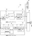
図2は、温度計測回路10が含まれる半導体集積回路を示す。半導体集積回路80は、図1に示される構成を有する温度計測回路10と、外部端子81を含む。温度計測回路10の比較器40は、温度センサ20が計測した温度と温度センサ30が計測した温度との比較結果に基づいて、温度センサ20が正常であるか否かを示す信号(Fail/Safe信号)を出力する。
[Fail / Safe signal]
FIG. 2 shows a semiconductor integrated circuit including the
比較器40が出力するFail/Safe信号は例えばデジタル信号であり、この信号のハイレベル及びローレベルの何れか一方は温度センサ20が正常である旨に対応し、他方は温度センサ20が異常である旨に対応する。比較器40は、Fail/Safe信号を外部端子81に出力し、外部端子81に接続されたチップ外のデバイス(外部周辺回路)に、温度センサ20が正常であるか、或いは異常であるかを通知する。これに代えて、又は加えて、比較器40は、チップ内のデバイスに温度センサ20が正常であるか、或いは異常であるかを通知してもよい。
The Fail / Safe signal output from the
[BIST]
デジタル回路で構成される温度センサ20のロジック部24、及び温度センサ30は、BISTが可能である。図1では図示を省略しているが、ロジック部24及び温度センサ30は、それぞれBIST回路を有している。ロジック部24及び温度センサ30において、BIST回路を動作させることで、ロジック部24及び温度センサ30のそれぞれの動作確認が可能である。
[BIST]
The
図3は、デジタル回路に実装されるBIST回路を示す。デジタル回路90は、BIST回路91、複数のFF(Flip Flop)92、及び期待値比較回路93を有する。BIST回路91は、テストパターンを発生する。各FF(スキャンFF)92は、スキャンチェーンを構成する。BIST回路91から出力されたテストパターンは、複数のFF92を通じて、図3では3つのFF92を通じて期待値比較回路93に入力される。
FIG. 3 shows a BIST circuit mounted on a digital circuit. The
期待値比較回路93は、複数のFF92を通じて入力された信号と、テストパターンに対する期待値と比較する。期待値比較回路93において期待値との比較が行われることで、BIST回路91が配置されたデジタル回路が正常に動作しているか否かが確認される。期待値比較回路93は、比較の結果を、チップ内のCPU94及び外部出力端子95の少なくとも一方に出力する。期待値比較回路93は、例えば入力された信号と期待値とが一致する場合は、BISTの結果PassをCPU94及び外部出力端子95の少なくとも一方に出力する。期待値比較回路93は、一致しない場合は、BISTの結果FailをCPU94及び外部出力端子95の少なくとも一方に出力する。
The expected
温度センサ20のロジック部24については、上記のBIST回路91を実装することで、例えばチップの選別時に、欠陥不良のスクリーニングが可能である。半導体集積回路において何らかの処理を実行させるユーザモード時においても、BIST回路91を動作させることで、ロジック部24において故障が生じた場合に、その検出が可能である。ユーザモード時においては、起動から終了までの動作サイクルの間に、BIST回路91が少なくとも1回起動されることとしてもよい。
By mounting the above-mentioned
温度センサ30についても、上記のBIST回路91を動作させることで、BISTが可能であり、選別時及びユーザモード時の双方において、欠陥又は故障が検出可能である。BISTを通じて、温度センサ30が正常に動作していることが確認された状態で温度計測回路10が使用された場合、温度デジタル値D2は、正常な温度を示す値であることが保証される。この保証された温度デジタル値D2と温度センサ20から出力される温度デジタル値D1とを比較することで、温度センサ20が正常に動作していない場合に、その検出が可能である。
By operating the above-mentioned
なお、温度センサ20に含まれるAD変換器23が正常に動作しているか否かは、例えば選別時に、外部からテスト用アナログ電圧入力端子26を通じてAD変換器23に特定電圧を入力し、温度データレジスタ25に格納されたデジタル値が特定電圧に対応するものであるか否かを調べることで、判断可能である。ユーザモード時は、例えば半導体集積回路に含まれるDAC(Digital to Analog Convertor)を用いて任意の電圧をテスト用アナログ電圧入力端子26に入力し、温度データレジスタ25に所望のデジタル値が可能されているか否かを調べることで、故障の有無の判断が可能である。
Whether the
温度検知部21については、例えばウエハテスト時に、ウエハステージ温度を温度検知部21に加えられる温度(ジャンクション温度Tj)として、その温度に対応する温度デジタル値D1が温度データレジスタ25に格納されているか否かを調べることで、欠陥検出が可能である。ユーザモード時は、上記したようにBSIT可能な温度センサ30を用い、保証された温度デジタル値D2と温度デジタル値D1とを比較することで、温度検知部21の故障の検出が可能である。
Regarding the
[動作手順]
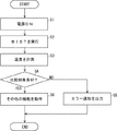
図4は、温度計測回路10における動作手順を示す。温度計測回路10を含む半導体集積回路80(図2を参照)の電源がオンになると(ステップS1)、図示しないプロセッサは、温度センサ20のロジック部24、及び温度センサ30のそれぞれにおいてBIST回路91(図3を参照)を動作させる。ロジック部24及び温度センサ30は、それぞれBISTを実行する(ステップS2)。
[Operation procedure]
FIG. 4 shows an operation procedure in the
BISTの実行後、ロジック部24及び温度センサ30において故障が発生していない場合、温度センサ20及び温度センサ30は、それぞれ温度計測を実行する(ステップS3)。ステップS3では、温度センサ20が温度計測を実行することで、温度デジタル値D1が得られる。また、温度センサ30が温度計測を実行することで、温度デジタル値D2が得られる。
If no failure has occurred in the
比較器40は、2つの温度センサで得られた温度計測結果、つまり温度デジタル値D1と温度デジタル値D2とを比較する。比較器40は、比較結果が良好である否か、つまり両者が合致するか否かを判断する(ステップS4)。比較器40は、例えば温度デジタル値D1が示す温度と温度デジタル値D2が示す温度とが、ほぼ同じ温度である場合は、両者が合致すると判断する。比較器40は、ステップS4で両者が合致しないと判断した場合は、温度センサ20が異常である旨を示す信号出力し、エラーを通知する(ステップS5)。ステップS4で両者が合致すると判断された場合、プロセッサは、他の処理を実行する(ステップS6)。
The
[動作例]
図5は、温度センサ20で計測された温度と、温度センサ30で計測された温度とを示す。図5において、温度センサ20の温度計測結果(メイン)は丸印でプロットされ、温度センサ30の温度計測結果(サブ)はひし形でプロットされている。図5においては、温度センサ30の誤差範囲が点線で示されている。図5では、温度センサ30の温度精度が±10℃であるとし、温度センサ30で計測された温度を基準に±10℃の範囲を誤差範囲として示している。
[Operation example]
FIG. 5 shows the temperature measured by the
比較器40は、例えば温度デジタル値D1が示す温度と温度デジタル値D2が示す温度との差が、温度センサ30の温度精度の範囲内であれば、温度センサ20が正常である旨を示す信号を出力する。別の言い方をすれば、比較器40は、温度デジタル値D1が示す温度が、温度デジタル値D2が示す温度を基準とした温度センサ30の温度誤差の範囲内に含まれる場合、温度センサ20が正常である旨を示す信号を出力する。
The
例えば、図5に示されるある時刻t11において図4のステップS3が実行され、温度センサ20が出力した温度デジタル値D1が103℃を示し、温度センサ30が出力した温度デジタル値D2が95℃を示したとする。この場合、温度センサ20の温度計測結果103℃は、温度センサ30の温度計測結果95℃を基準とした±10℃の範囲内であるため、比較器40は、温度センサ20が正常である旨を示す信号を出力する。
For example, at a certain time t11 shown in FIG. 5, step S3 in FIG. 4 is executed, and the temperature digital value D1 output from the
次に、時刻t12においてステップS3が実行され、温度センサ20が出力した温度デジタル値D1が105℃を示し、温度センサ30が出力した温度デジタル値D2が111℃を示したとする。この場合も、温度センサ20の温度計測結果105℃は、温度センサ30の温度計測結果111℃を基準とした±10℃の範囲内であるため、比較器40は、温度センサ20が正常である旨を示す信号を出力する。
Next, at time t12, step S3 is executed, and it is assumed that the temperature digital value D1 output from the
さらに、時刻t13においてステップS3が実行され、温度センサ20が出力した温度デジタル値D1が105℃を示し、温度センサ30が出力した温度デジタル値D2が117℃を示したとする。この場合は、温度センサ20の温度計測結果105℃は、温度センサ30の温度計測結果117℃を基準とした±10℃の範囲からは外れる。温度センサ30は、ステップS2で実行されたBISTによって正常に動作することが確認されており、温度センサ30の温度計測結果は正しいことが保証されている。従って、温度デジタル値D1と温度デジタル値D2とが異なる温度を示す場合、温度センサ20において正しい温度計測結果が得られていないと判断できる。この場合、比較器40は、温度センサ20が異常である旨を示す信号を出力する。
Further, at time t13, step S3 is executed, and it is assumed that the temperature digital value D1 output from the
[まとめ]
本実施形態では、温度計測回路10は、温度センサ20と温度センサ30とを有する。温度センサ20は温度に依存して抵抗値が変化する抵抗素子を用いた温度センサであるのに対し、温度センサ30は温度に依存した周期で発振するリングオシレータを用いた温度センサである。本実施形態では、温度計測回路10は、種類の異なる2つの温度センサを含んでおり、双方の温度センサで得られた温度計測結果を比較する。本実施形態では、ヘテロジニアスな多重化システムで温度センサを構成しており、同じ構成の温度センサを複数用いた場合に比べて共通原因に起因する故障は発生しにくい。
[Summary]
In the present embodiment, the
本実施形態では、特に、温度センサ20において温度検知にアナログ回路が用いられ、温度センサ30において温度検知にデジタル回路が用いられている。温度センサ20において温度検知部21をアナログ電源で動作させ、温度センサ30において温度検知部であるリングオシレータ31をデジタル電源で動作させることで、共通原因に起因する故障を軽減することが可能である。本実施形態では、共通原因に起因する故障を軽減できるため、実装に時間を要するレイアウト対策などの実施を省略することが可能である。
In the present embodiment, in particular, the
さらに、本実施形態において、温度センサ30はデジタル回路で構成されており、温度センサ30においてBISTが可能である。BISTにより、ユーザモード時においても、温度センサ30が正常に動作していることが確認可能であり、温度センサ30が計測した温度が正しいことを保証できる。本実施形態では、正しいことが保証された温度センサ30の温度計測結果と温度センサ20の温度計測結果とを比較することで、温度センサ20の温度計測結果が正しいものであるか否かの判断が可能である。
Further, in the present embodiment, the
特に、温度センサ20と温度センサ30とを半導体集積回路と同じチップ上に実装する場合、1チップの半導体デバイス内で温度計測値を保証することが可能である。温度センサ20の温度計測値が正しいことが保証されない場合、温度センサ20が正常に動作しなくなった場合に備えて、半導体デバイスの外部に保護用(多重化用)の外部温度センサを別途配置することも考えられる。しかしながら、その場合、システムでの部品点数が増加する。本実施形態では、1つのチップ内で温度センサ20の温度計測値が保証されるため、別途外部温度センサを配置する場合に比べて、部品点数を削減できる効果もある。
In particular, when the
さらに、本実施形態では、サブ温度センサとして用いられる温度センサ30は、リングオシレータを含むデジタル回路で構成されており、AD変換器の搭載が不要である。また、温度センサ30においては、アナログ電源の回路設計が不要である。このため、温度センサ30は、メイン温度センサとして用いられる温度センサ20に比べて、一例として1/4程度の実装面積で実装可能であり、面積削減効果がある。
Further, in the present embodiment, the
特許文献1との比較では、特許文献1では温度センサを3個以上必要とするのに対し、本実施形態では温度センサは2つでよい。また、特許文献1では多数決論理が必要であるのに対し、本実施形態では2つの温度センサの温度計測結果を比較すればよく、多数決論理は不要である。従って、本実施形態では、特許文献1に比べて回路規模を縮小できる。
In comparison with
[実施形態2]
図6は、実施形態2に係る温度計測回路を示す。図1に示される実施形態1に係る温度計測回路10と、本実施形態に係る温度計測回路10aとの違いは、温度センサ30の温度データレジスタ37が、CPUデータバス50にも温度デジタル値D2を出力する点である。本実施形態では、温度計測回路10aが実装される半導体集積回路のCPUは、CPUデータバス50を通じて、温度デジタル値D1に加えて、温度デジタル値D2を参照できる。
[Embodiment 2]
FIG. 6 illustrates a temperature measurement circuit according to the second embodiment. The difference between the
実施形態に1において、CPUは、例えば温度センサ20の温度データレジスタ25から温度デジタル値D1を取得し、取得した温度に応じて処理を実行する。本実施形態では、CPUは、温度センサ30の温度データレジスタ37から温度デジタル値D2も取得した、取得した温度に応じて処理を実行できる。このように、本実施形態では、温度デジタル値D2は、温度センサ20の正常又は異常の判定のためにだけでなく、CPUにおける処理のためにも利用できる。
In the first embodiment, the CPU acquires the digital temperature value D1 from the temperature data register 25 of the
CPUは、例えば、温度デジタル値D1が示す温度、及び温度デジタル値D2が示す温度が、それぞれ所定の温度範囲から外れているか否かをチェックする。より詳細には、CPUは、温度デジタル値D1が示す温度、及び温度デジタル値D2が示す温度が、それぞれ所定温度範囲の下限に対応付けられる温度しきい値以下であるか、又は所定温度範囲の上限に対応付けられる温度しきい値以上であるか否かを判断する。 The CPU checks, for example, whether the temperature indicated by the digital temperature value D1 and the temperature indicated by the digital temperature value D2 are out of predetermined temperature ranges. More specifically, the CPU determines that the temperature indicated by the temperature digital value D1 and the temperature indicated by the temperature digital value D2 are respectively equal to or lower than a temperature threshold value associated with the lower limit of the predetermined temperature range, or It is determined whether the temperature is equal to or higher than the temperature threshold value associated with the upper limit.
CPUは、温度デジタル値D1が示す温度、及び温度デジタル値D2が示す温度の少なくとも一方が、所定温度範囲に収まっていない場合、所定の処理を実行する。つまり、CPUは、温度デジタル値D1が示す温度、及び温度デジタル値D2が示す温度の少なくとも一方が、所定温度範囲の上限に対応付けられる温度しきい値以下であるか、又は所定温度範囲の下限に対応付けられる温度しきい値以上である場合、所定の処理を実行する。このように、2つの温度センサ20及び温度センサ30の温度計測結果を利用することで、温度センサ20の温度計測結果のみを用いる場合に比べて、よりロバストなシステムを構築できる。
The CPU executes a predetermined process when at least one of the temperature indicated by the temperature digital value D1 and the temperature indicated by the temperature digital value D2 does not fall within the predetermined temperature range. That is, the CPU determines that at least one of the temperature indicated by the temperature digital value D1 and the temperature indicated by the temperature digital value D2 is equal to or lower than a temperature threshold value associated with the upper limit of the predetermined temperature range, or the lower limit of the predetermined temperature range. If the temperature is equal to or higher than the temperature threshold value associated with the above, a predetermined process is executed. As described above, by using the temperature measurement results of the two
[動作例]
図7は、温度センサ20で計測された温度と、温度センサ30で計測された温度とを示す。図7において、温度センサ20の温度計測結果(メイン1)は丸印でプロットされ、温度センサ30の温度計測結果(メイン2)はひし形でプロットされている。また、温度センサ30の誤差範囲が点線で示されている。図7においても、温度センサ30の温度精度が±10℃であるとし、温度センサ30で計測された温度を基準に±10℃の範囲を誤差範囲として示している。図7には、温度計測回路10が実装される半導体集積回路の動作保証温度範囲の上限も示されている。
[Operation example]
FIG. 7 shows the temperature measured by the
例えば、図7に示されるある時刻t21において図4のステップS3が実行され、温度センサ20が出力した温度デジタル値D1が140℃を示し、温度センサ30が出力した温度デジタル値D2が135℃を示したとする。この場合、温度センサ20の温度計測結果140℃は、温度センサ30の温度計測結果135℃を基準とした±10℃の範囲内であるため、温度センサ20は正常である旨を示す信号が出力される。また、温度センサ20の温度計測結果140℃、及び温度センサ30の温度計測結果135℃は、共に動作保証温度範囲の上限である150℃よりも低いため、CPUは、通常の処理を続行する。
For example, at a certain time t21 shown in FIG. 7, step S3 in FIG. 4 is executed, the temperature digital value D1 output from the
次に、時刻t22においてステップS3が実行され、温度センサ20が出力した温度デジタル値D1が149℃を示し、温度センサ30が出力した温度デジタル値D2が137℃を示したとする。この場合、双方の温度計測結果は動作保証温度範囲の上限よりも低いものの、温度センサ20の温度計測結果149℃は、温度センサ30の温度計測結果137℃を基準とした±10℃の範囲からは外れる。この場合は、比較器40から、温度センサ20が異常である旨を示す信号が出力され、CPUは、温度センサ20が異常であることから、所定の処理、例えばセーフティ処理を実施する。
Next, at time t22, step S3 is executed, and it is assumed that the temperature digital value D1 output from the
さらに、時刻t23においてステップS3が実行され、温度センサ20が出力した温度デジタル値D1が148℃を示し、温度センサ30が出力した温度デジタル値D2が152℃を示したとする。この場合、温度センサ20の温度計測結果148℃は、温度センサ30の温度計測結果152℃を基準とした±10℃の範囲内であるため、温度センサ20は正常である旨を示す信号が出力される。しかしながら、CPUは、温度センサ30の温度計測結果152℃が動作保証温度範囲の上限を超えていると判定し、この場合も、所定の処理、例えばセーフティ処理を実施する。仮に、CPUが温度センサ20の温度計測結果のみを参照するとした場合、その温度計測結果149℃は動作保証温度範囲150℃よりも低いため、セーフティ処理は実施されない。本実施形態では、CPUが2つの温度センサの温度計測結果を取得し、少なくとも一方が動作保証温度範囲の上限を超えていた場合にセーフティ処理を実施するように構成することで、よりロバストなシステムを構築できる。
Further, at time t23, step S3 is executed, and it is assumed that the temperature digital value D1 output from the
図8は、温度センサ20で計測された温度と、温度センサ30で計測された温度との別の例を示す。図7の場合と同様に、図8において、温度センサ20の温度計測結果(メイン1)は丸印でプロットされ、温度センサ30の温度計測結果(メイン2)はひし形でプロットされている。また、温度センサ30の誤差範囲が点線で示されている。図8においても、温度センサ30の温度精度が±10℃であるとし、温度センサ30で計測された温度を基準に±10℃の範囲を誤差範囲として示している。図8には、温度計測回路10が実装される半導体集積回路の動作保証温度範囲の下限も示されている。
FIG. 8 shows another example of the temperature measured by the
例えば、図8に示されるある時刻t31において図4のステップS3が実行され、温度センサ20が出力した温度デジタル値D1が−34℃を示し、温度センサ30が出力した温度デジタル値D2が−42℃を示したとする。この場合、温度センサ20の温度計測結果−34℃は、温度センサ30の温度計測結果−42℃を基準とした±10℃の範囲内であるため、温度センサ20は正常である旨を示す信号が出力される。しかしながら、CPUは、温度センサ30の温度計測結果−42℃が動作保証温度範囲の下限よりも低いと判定し、所定の処理、例えばセーフティ処理を実施する。仮に、CPUが温度センサ20の温度計測結果のみを参照するとした場合、その温度計測結果−34℃は動作保証温度範囲−40℃よりも高いため、セーフティ処理は実施されない。本実施形態では、CPUが2つの温度センサの温度計測結果を取得し、少なくとも一方が動作保証温度範囲の下限よりも低い場合にセーフティ処理を実施するように構成することで、よりロバストなシステムを構築できる。
For example, at a certain time t31 shown in FIG. 8, step S3 in FIG. 4 is executed, the temperature digital value D1 output from the
次に、時刻t32においてステップS3が実行され、温度センサ20が出力した温度デジタル値D1が−24℃を示し、温度センサ30が出力した温度デジタル値D2が−30℃を示したとする。この場合、温度センサ20の温度計測結果−24℃は、温度センサ30の温度計測結果−30℃を基準とした±10℃の範囲内であるため、温度センサ20は正常である旨を示す信号が出力される。また、温度センサ20の温度計測結果−24℃、及び温度センサ30の温度計測結果−30℃は、共に動作保証温度範囲の下限である−40よりも高いため、CPUは、通常の処理を続行する。
Next, at time t32, step S3 is executed, and it is assumed that the temperature digital value D1 output from the
さらに、時刻t23においてステップS3が実行され、温度センサ20が出力した温度デジタル値D1が−14℃を示し、温度センサ30が出力した温度デジタル値D2が−27℃を示したとする。この場合、双方の温度計測結果は動作保証温度範囲の下限よりも高いものの、温度センサ20の温度計測結果−14℃は、温度センサ30の温度計測結果−27℃を基準とした±10℃の範囲からは外れる。この場合は、比較器40から、温度センサ20が異常である旨を示す信号が出力され、CPUは、温度センサ20が異常であることから、所定の処理、例えばセーフティ処理を実施する。
Further, at time t23, step S3 is executed, and it is assumed that the temperature digital value D1 output from the
[まとめ]
本実施形態では、温度センサ20の温度データレジスタ25と、温度センサ30の温度データレジスタ37とがCPUデータバス50に接続されており、CPUは、温度センサ20の温度計測結果と温度センサ30の温度計測結果の双方を参照できる。このようにすることで、CPUは、2つの温度センサで計測された温度が、それぞれ所定の範囲に収まっているか否かを判定することができる。本実施形態では、CPUは、温度センサ20の温度計測結果と温度センサ30の温度計測結果の何れか一方が所定の範囲から外れたときに、所定の処理を実行することが可能となり、温度センサ20の温度計測結果のみを参照する場合に比べて、より確度の高い温度制御を実現できる。
[Summary]
In the present embodiment, the temperature data register 25 of the
[実施形態3]
図9は、実施形態3に係る温度計測回路を示す。本実施形態に係る温度計測回路10bは、図1に示される実施形態1に係る温度計測回路10の構成に加えて、タイマ55を有する。本実施形態は、実施形態2と組み合わせることも可能である。つまり、本実施形態に係る温度計測回路10bが、図6に示される実施形態2に係る温度計測回路10aの構成に加えて、タイマ55を有する構成を採用することも可能である。
[Embodiment 3]
FIG. 9 illustrates a temperature measurement circuit according to the third embodiment. The
タイマ55は、温度センサ20のAD変換器23、及び温度センサ30の演算回路35に対して計測トリガを出力する。温度センサ20及び温度センサ30は、タイマ55から出力された計測トリガに応答して温度計測を実施し、その結果をそれぞれ温度データレジスタ25及び温度データレジスタ37に格納する。
The
本実施形態において、温度計測回路10bが実装される半導体集積回路のCPUは、CPUデータバス50を通じて、タイマ55に、温度連続計測モードを通知する。タイマ55は、温度連続計測モードの通知を受けると、周期的に計測トリガをAD変換器23及び演算回路35に出力する。タイマ55から周期的に計測トリガが出力されることで、温度センサ20及び温度センサ30は、周期的に温度計測を実施する。比較器40は、周期的に得られる温度デジタル値D1と温度デジタル値D2とを比較し、比較結果に基づいて、Fail/Safe信号を周期的に出力する。
In the present embodiment, the CPU of the semiconductor integrated circuit on which the
本実施形態に係る温度計測回路10bは、タイマ55を有している。本実施形態では、タイマ55から、周期的、例えば一定の時間間隔で計測トリガを出力することで、CPU上で実行されるソフトウェアの介在なく、一定の時間間隔で、温度センサ20が故障しているか否かの検査が可能である。
The
[マイクロコンピュータユニット]
ここで、上記各実施形態に係る温度計測回路は、マイクロコンピュータユニットに搭載可能である。図10は、マイクロコンピュータユニットを示す。マイクロコンピュータユニット100は、CPU101、ROM102、RAM103、入出力ポート104、周辺回路105、及びCPUバス106を含む。マイクロコンピュータユニット100は、例えば自動車などの車両に搭載される車両搭載用のマイクロコンピュータユニットとして構成される。マイクロコンピュータユニット100は、車両において、例えばADAS(Advanced Driver Assistance System:先進運転支援システム)に用いられる。
[Microcomputer unit]
Here, the temperature measurement circuit according to each of the above embodiments can be mounted on a microcomputer unit. FIG. 10 shows a microcomputer unit. The
CPU101は、プロセッサであり、マイクロコンピュータユニットにおいて各種処理を実行する。CPU101は、CPUバス106を介して、RAM103、入出力ポート104、及び周辺回路105などに接続される。CPUバス106には、図1などに示されるCPUデータバス50が含まれる。ROM102は、例えばフラッシュメモリなどの不揮発性メモリであり、CPU101によって実行されるプログラムなどを格納する。CPU101は、ROM102から読み出したプログラムを実行して各種処理を実行する。RAM103は、各種データを格納する揮発性のメモリである。
The
入出力ポート104は、マイクロコンピュータユニット100と外部周辺回路110及び他デバイス120との間で信号の入出力を行う。入出力ポート104には、図1に示されるテスト用アナログ電圧入力端子26、図2に示される外部端子81、及び図3に示される外部出力端子95などが含まれる。周辺回路105は、マイクロコンピュータユニット100に内蔵される各種周辺回路を含む。周辺回路105には、例えば図1に示される温度センサ20、温度センサ30、及び比較器40などが含まれる。周辺回路105は、入出力ポート104を通じて他デバイス120との間で通信を行うことが可能である。
The input /
外部周辺回路110は、電源111、発振回路112、及びリセット回路113などを含む。電源111は、マイクロコンピュータユニット100に対して電源供給を行う。電源111は、図1に示される領域60に電源供給を行うためのアナログ用電源と、領域70に電源供給を行うためのデジタル用電源とを含んでいてもよい。発振回路112は、マイクロコンピュータユニット100にクロック信号などを供給する。リセット回路113は、マイクロコンピュータユニット100をリセットする。リセット回路113は、例えば、外部端子81(図2を参照)から温度センサ20が異常である旨を示すFail/Safe信号が出力されると、マイクロコンピュータユニット100をリセットする。
The external
マイクロコンピュータユニット100の一部として実装される温度計測回路10において、温度センサ20の温度計測結果と温度センサ30の温度計測結果とを一定間隔で比較するシステムを組みことで、マイクロコンピュータユニット100単体で、ISO26262に対応させることが可能となる。また、温度計測回路10において、温度センサ30の温度検知部はリングオシレータ31によるデジタル回路で構成されており、温度検知部のBISTを可能とすることで、ISO26262のLatent対策としても有効となる。
In the
[変形例]
なお、図4では、半導体集積回路の起動時(電源オン時)にステップS2を実行し、温度センサ30においてBISTを行う例を説明したが、これには限定されない。温度センサ30のBISTは、半導体集積回路の処理開始から処理終了までの動作サイクルにおいて、少なくとも1回実行されればよく、その実行タイミングは特に限定されない。例えば、電源オン時にBISTを実行するのに代えて、電源オフ時に、半導体集積回路のシャットダウンの処理の中で温度センサ30のBISTを実行することとしてもよい。
[Modification]
Note that FIG. 4 illustrates an example in which step S2 is executed when the semiconductor integrated circuit is started (when the power is turned on) and BIST is performed in the
上記実施形態では、比較器40が、温度センサ20の温度計測結果と温度センサ30の温度計測結果との差に基づいて、温度センサ20が正常であるか否かを示す信号を出力する例を説明したが、これには限定されない。例えば、比較器40において、温度センサ20の温度計測結果と温度センサ30の温度計測結果との相関を演算し、相関が取れているか否かに基づいて、温度センサ20が正常であるか否かを示す信号を出力することとしてもよい。
In the above embodiment, an example in which the
上記各実施形態では、温度計測回路がマイクロコンピュータユニットに組み込まれる例について説明したが、これには限定されない。温度計測回路は、温度計測機能を有する他の集積回路(IC:Integrated Circuit)として構成されてもよい。 In each of the above embodiments, the example in which the temperature measurement circuit is incorporated in the microcomputer unit has been described, but the present invention is not limited to this. The temperature measurement circuit may be configured as another integrated circuit (IC: Integrated Circuit) having a temperature measurement function.
以上、本発明者によってなされた発明を実施の形態に基づき具体的に説明したが、本発明は既に述べた実施の形態に限定されるものではなく、その要旨を逸脱しない範囲において種々の変更が可能であることはいうまでもない。 As described above, the invention made by the inventor has been specifically described based on the embodiment. However, the present invention is not limited to the embodiment described above, and various changes may be made without departing from the gist of the invention. It goes without saying that it is possible.
10:温度計測回路
20:温度センサ
21:温度検知部
22:マルチプレクサ
23:AD変換器
24:ロジック部
25:温度データレジスタ
26:テスト用アナログ電圧入力端子
30:温度センサ
31:リングオシレータ
32:タイマモジュール
33:エッジセレクタ
34:カウンタ
35:演算回路
36:ロジック部
37:温度データレジスタ
40:比較器
50:CPUデータバス
55:タイマ
60、70:領域
80:半導体集積回路
81:外部端子
90:デジタル回路
91:BIST回路
92:FF(フリップフロップ)
93:期待値比較回路
94:CPU
95:外部出力端子
100:マイクロコンピュータユニット
101:CPU
102:ROM
103:RAM
104:入出力ポート
105:周辺回路
106:CPUバス
110:外部周辺回路
111:電源
112:発振回路
113:リセット回路
120:他デバイス
10: Temperature measurement circuit 20: Temperature sensor 21: Temperature detection unit 22: Multiplexer 23: AD converter 24: Logic unit 25: Temperature data register 26: Analog voltage input terminal for test 30: Temperature sensor 31: Ring oscillator 32: Timer Module 33: Edge selector 34: Counter 35: Arithmetic circuit 36: Logic unit 37: Temperature data register 40: Comparator 50: CPU data bus 55: Timer 60, 70: Area 80: Semiconductor integrated circuit 81: External terminal 90: Digital Circuit 91: BIST circuit 92: FF (flip-flop)
93: expected value comparison circuit 94: CPU
95: external output terminal 100: microcomputer unit 101: CPU
102: ROM
103: RAM
104: input / output port 105: peripheral circuit 106: CPU bus 110: external peripheral circuit 111: power supply 112: oscillation circuit 113: reset circuit 120: other device
Claims (17)
温度に依存した周期で発振するリングオシレータを含み、前記リングオシレータが出力する発振信号に基づいて第2の温度デジタル値を生成する第2の温度センサと、
前記第1の温度デジタル値と前記第2の温度デジタル値とを比較し、該比較の結果に基づいて、前記第1の温度センサが正常であるか異常であるかを示す信号を出力する比較器とを備える温度計測回路。 A first temperature sensor including a temperature detection unit including a resistance element whose resistance value changes according to a temperature, and an analog-to-digital converter that converts a voltage value of the resistance element into a first temperature digital value;
A second temperature sensor that includes a ring oscillator that oscillates at a cycle depending on temperature, and that generates a second temperature digital value based on an oscillation signal output by the ring oscillator;
Comparing the first digital temperature value with the second digital temperature value and outputting a signal indicating whether the first temperature sensor is normal or abnormal based on a result of the comparison; Temperature measurement circuit comprising a vessel .
前記プロセッサから読み出し可能なメモリと、
温度に応じて抵抗値が変化する抵抗素子を含む温度検知部と、前記抵抗素子の電圧値を第1の温度デジタル値に変換するアナログデジタル変換器とを含む第1の温度センサと、
温度に依存した周期で発振するリングオシレータを含み、前記リングオシレータが出力する発振信号に基づいて第2の温度デジタル値を生成する第2の温度センサと、
前記第1の温度デジタル値と前記第2の温度デジタル値とを比較し、前記第1の温度センサが正常であるか異常であるかを示す信号を出力する比較器とを備えるマイクロコンピュータユニット。 A processor,
A memory readable from the processor;
A first temperature sensor including a temperature detection unit including a resistance element whose resistance value changes according to a temperature, and an analog-to-digital converter that converts a voltage value of the resistance element into a first temperature digital value;
A second temperature sensor that includes a ring oscillator that oscillates at a cycle depending on temperature, and that generates a second temperature digital value based on an oscillation signal output by the ring oscillator;
A microcomputer unit comprising: a comparator that compares the first digital temperature value with the second digital temperature value and outputs a signal indicating whether the first temperature sensor is normal or abnormal.
前記プロセッサは、データバスを通じて前記第1の温度データレジスタに格納された前記第1の温度デジタル値を参照する請求項8に記載のマイクロコンピュータユニット。 The first temperature sensor further includes a logic unit having a first temperature data register storing the first digital temperature value,
9. The microcomputer unit according to claim 8, wherein the processor refers to the first temperature digital value stored in the first temperature data register via a data bus.
前記プロセッサは、前記ビルトインセルフテスト回路を動作させて前記ロジック部においてセルフテストを実行させる請求項9に記載のマイクロコンピュータユニット。 The logic unit further includes a built-in self test circuit,
10. The microcomputer unit according to claim 9, wherein the processor operates the built-in self-test circuit to execute a self-test in the logic unit.
前記プロセッサは、データバスを通じて前記第2の温度データレジスタに格納された前記第2の温度デジタル値を参照する請求項8に記載のマイクロコンピュータユニット。 The second temperature sensor further includes a second temperature data register storing the second temperature digital value,
9. The microcomputer unit according to claim 8, wherein the processor refers to the second temperature digital value stored in the second temperature data register via a data bus.
前記プロセッサは、前記ビルトインセルフテスト回路を動作させて前記第2の温度センサにおいてセルフテストを実行させる請求項8に記載のマイクロコンピュータユニット。 The second temperature sensor further includes a built-in self-test circuit;
The microcomputer unit according to claim 8 , wherein the processor operates the built-in self-test circuit to execute a self-test in the second temperature sensor.
第2の温度センサに含まれる、温度に依存した周期で発振するリングオシレータが出力する発振信号に基づいて第2の温度デジタル値を生成し、
前記第1の温度デジタル値と前記第2の温度デジタル値とを比較し、
前記比較の結果に基づいて、前記第1の温度センサが正常であるか異常であるかを示す信号を出力する温度計測方法。 Converting a voltage value of a resistance element included in the first temperature sensor, the resistance value of which changes according to temperature, into a first temperature digital value;
A second temperature digital value is generated based on an oscillation signal output from a ring oscillator included in the second temperature sensor and oscillating at a cycle dependent on temperature,
Comparing the first digital temperature value with the second digital temperature value,
A temperature measurement method for outputting a signal indicating whether the first temperature sensor is normal or abnormal based on a result of the comparison.
Priority Applications (3)
| Application Number | Priority Date | Filing Date | Title |
|---|---|---|---|
| JP2016235730A JP6678094B2 (en) | 2016-12-05 | 2016-12-05 | Temperature measurement circuit, method, and microcomputer unit |
| US15/795,112 US10670478B2 (en) | 2016-12-05 | 2017-10-26 | Temperature measurement circuit and method, and microcomputer unit |
| CN201711096414.9A CN108151901B (en) | 2016-12-05 | 2017-11-09 | Temperature measuring circuit and method, and microcomputer unit |
Applications Claiming Priority (1)
| Application Number | Priority Date | Filing Date | Title |
|---|---|---|---|
| JP2016235730A JP6678094B2 (en) | 2016-12-05 | 2016-12-05 | Temperature measurement circuit, method, and microcomputer unit |
Publications (3)
| Publication Number | Publication Date |
|---|---|
| JP2018091741A JP2018091741A (en) | 2018-06-14 |
| JP2018091741A5 JP2018091741A5 (en) | 2019-06-06 |
| JP6678094B2 true JP6678094B2 (en) | 2020-04-08 |
Family
ID=62240040
Family Applications (1)
| Application Number | Title | Priority Date | Filing Date |
|---|---|---|---|
| JP2016235730A Active JP6678094B2 (en) | 2016-12-05 | 2016-12-05 | Temperature measurement circuit, method, and microcomputer unit |
Country Status (3)
| Country | Link |
|---|---|
| US (1) | US10670478B2 (en) |
| JP (1) | JP6678094B2 (en) |
| CN (1) | CN108151901B (en) |
Families Citing this family (10)
| Publication number | Priority date | Publication date | Assignee | Title |
|---|---|---|---|---|
| JP6598592B2 (en) * | 2015-08-28 | 2019-10-30 | ルネサスエレクトロニクス株式会社 | Semiconductor integrated circuit and electronic control unit |
| JP7055084B2 (en) * | 2018-09-20 | 2022-04-15 | ルネサスエレクトロニクス株式会社 | Semiconductor devices and control methods for semiconductor devices |
| US10664027B2 (en) * | 2018-10-09 | 2020-05-26 | Intel Corporation | Methods, systems and apparatus for dynamic temperature aware functional safety |
| JP7134160B2 (en) * | 2019-12-18 | 2022-09-09 | 本田技研工業株式会社 | Gas control device and gas control method |
| GB201919297D0 (en) * | 2019-12-24 | 2020-02-05 | Aronson Bill | Temperature sensing physical unclonable function (puf) authenication system |
| KR20210083537A (en) | 2019-12-27 | 2021-07-07 | 삼성전자주식회사 | Built-in self-test circuit and temperature measurement circuit including the same |
| CN111787428B (en) * | 2020-06-24 | 2022-03-08 | Oppo广东移动通信有限公司 | User terminal equipment |
| WO2023022022A1 (en) * | 2021-08-16 | 2023-02-23 | ローム株式会社 | Semiconductor device and vehicle-mounted device |
| EP4296639A1 (en) * | 2022-06-20 | 2023-12-27 | Carrier Fire & Security EMEA BV | Temperature sensor testing |
| CN117824870A (en) * | 2022-09-27 | 2024-04-05 | 华为技术有限公司 | Detection circuit, control method thereof and vehicle-mounted terminal equipment |
Family Cites Families (29)
| Publication number | Priority date | Publication date | Assignee | Title |
|---|---|---|---|---|
| JPH07111381B2 (en) | 1987-08-11 | 1995-11-29 | アンリツ株式会社 | Digital thermometer |
| JP2652961B2 (en) * | 1989-03-28 | 1997-09-10 | 日本電気株式会社 | Electronic component protection mechanism |
| JP2975259B2 (en) * | 1994-05-27 | 1999-11-10 | 核燃料サイクル開発機構 | Reactor fuel damage detection method |
| JPH11118619A (en) * | 1997-10-08 | 1999-04-30 | Koito Ind Ltd | Thermistor failure detecting method |
| US6695475B2 (en) * | 2001-05-31 | 2004-02-24 | Stmicroelectronics, Inc. | Temperature sensing circuit and method |
| US6853259B2 (en) * | 2001-08-15 | 2005-02-08 | Gallitzin Allegheny Llc | Ring oscillator dynamic adjustments for auto calibration |
| US7044633B2 (en) * | 2003-01-09 | 2006-05-16 | International Business Machines Corporation | Method to calibrate a chip with multiple temperature sensitive ring oscillators by calibrating only TSRO |
| US7168853B2 (en) * | 2003-01-10 | 2007-01-30 | International Business Machines Corporation | Digital measuring system and method for integrated circuit chip operating parameters |
| KR100518565B1 (en) * | 2003-04-04 | 2005-10-04 | 삼성전자주식회사 | Semiconductor temperature detector, semiconductor memory device providing for reduced self-refresh current by the detector and self-refresh method thereof |
| JP4082326B2 (en) * | 2003-10-02 | 2008-04-30 | 住友電気工業株式会社 | Method for measuring surface temperature of article to be heated, heating method using the same, and method for manufacturing optical fiber preform |
| KR100668739B1 (en) * | 2004-04-13 | 2007-01-26 | 주식회사 하이닉스반도체 | Oscillator Circuit |
| US7180380B2 (en) * | 2005-04-20 | 2007-02-20 | Advanced Micro Devices, Inc. | Zoned thermal monitoring |
| CN101216356A (en) * | 2007-01-04 | 2008-07-09 | 海尔集团公司 | Temperature sensor failure testing method and apparatus |
| CN102025368A (en) * | 2009-09-19 | 2011-04-20 | 无锡爱睿芯电子有限公司 | Temperature sensing oscillator and production method thereof as well as temperature frequency correction system |
| JP2012108087A (en) * | 2010-10-28 | 2012-06-07 | Seiko Instruments Inc | Temperature detector |
| GB201102070D0 (en) * | 2011-02-07 | 2011-03-23 | Nordic Semiconductor Asa | Semiconductor temperature sensors |
| JP5738141B2 (en) * | 2011-09-20 | 2015-06-17 | ルネサスエレクトロニクス株式会社 | Semiconductor device and temperature sensor system |
| CN202442811U (en) * | 2011-12-21 | 2012-09-19 | 无锡华润矽科微电子有限公司 | Structure of electronic temperature measurement circuit |
| KR101885857B1 (en) * | 2012-01-04 | 2018-08-06 | 삼성전자주식회사 | Temperature management unit, system on chip including the same and method of managing temperature in a system on chip |
| JP2013178118A (en) * | 2012-02-28 | 2013-09-09 | Honda Motor Co Ltd | Temperature detector |
| JP2014098614A (en) * | 2012-11-14 | 2014-05-29 | Renesas Electronics Corp | Temperature sensor and semiconductor device |
| US9658118B2 (en) * | 2012-11-16 | 2017-05-23 | Linear Technology Corporation | Precision temperature measurement devices, sensors, and methods |
| JP6186646B2 (en) * | 2013-03-29 | 2017-08-30 | 株式会社ケーヒン | Voltage detector |
| CN105486422A (en) * | 2014-09-16 | 2016-04-13 | 哈尔滨恒誉名翔科技有限公司 | High-precision temperature measurement device and method based on MSP430F149 |
| CN204115913U (en) * | 2014-09-19 | 2015-01-21 | 国家电网公司 | A kind of intelligent platinum resistance temperature measures tester |
| CN104596662B (en) * | 2014-12-08 | 2017-06-13 | 深圳市芯海科技有限公司 | Optimize digital temperature sensor on the piece of the linearity |
| CN105628243B (en) * | 2015-12-30 | 2018-04-20 | 清华大学深圳研究生院 | A kind of resistor-type temperature sensing chip |
| EP3340467B1 (en) * | 2016-12-22 | 2022-10-05 | NXP USA, Inc. | Digitally controlled oscillator with temperature compensation |
| KR20180082707A (en) * | 2017-01-10 | 2018-07-19 | 삼성전자주식회사 | Temperature compensated oscillation controller and temperature compensated crystal oscillator including the same |
-
2016
- 2016-12-05 JP JP2016235730A patent/JP6678094B2/en active Active
-
2017
- 2017-10-26 US US15/795,112 patent/US10670478B2/en active Active
- 2017-11-09 CN CN201711096414.9A patent/CN108151901B/en active Active
Also Published As
| Publication number | Publication date |
|---|---|
| JP2018091741A (en) | 2018-06-14 |
| US20180156675A1 (en) | 2018-06-07 |
| US10670478B2 (en) | 2020-06-02 |
| CN108151901A (en) | 2018-06-12 |
| CN108151901B (en) | 2021-10-29 |
Similar Documents
| Publication | Publication Date | Title |
|---|---|---|
| JP6678094B2 (en) | Temperature measurement circuit, method, and microcomputer unit | |
| US10359469B2 (en) | Non-intrusive on-chip analog test/trim/calibrate subsystem | |
| WO2011122365A1 (en) | Aging diagnosis circuit and aging diagnosis method for semiconductor integrated circuit | |
| JP6637374B2 (en) | Semiconductor device and temperature sensor | |
| JP2018091741A5 (en) | ||
| CN110999086A (en) | Fault tolerant clock monitor system | |
| US9970982B2 (en) | Apparatus and a method for providing an output parameter and a sensor device | |
| US7661878B1 (en) | On-chip temperature sensor for an integrated circuit | |
| US10461721B2 (en) | Semiconductor apparatus, degradation value determination system and processing system | |
| JP6358107B2 (en) | Power monitoring circuit | |
| US10749510B2 (en) | Semiconductor device and control methods thereof | |
| JP6323267B2 (en) | Semiconductor device and method for controlling semiconductor device | |
| JP2012222192A (en) | Semiconductor integrated circuit and malfunction prevention method | |
| CN106896317B (en) | Circuit debugging method and circuit debugging system executed by scan chain of scan test | |
| JP5734615B2 (en) | Inspection apparatus and method | |
| US8742779B2 (en) | Semiconductor device and abnormality prediction method thereof | |
| JP2018017544A (en) | Temperature detection circuit and temperature detection method | |
| JP7135497B2 (en) | data processor | |
| US20160291078A1 (en) | Semiconductor apparatus and system | |
| US7632011B1 (en) | Integrated circuit temperature sensor systems and methods | |
| JP6010645B2 (en) | Inspection apparatus and method | |
| KR20060052591A (en) | Semiconductor integrated circuit device | |
| KR102078383B1 (en) | Power observe apparatus and power observe system using thereof | |
| US10979061B2 (en) | Analog-digital conversion device | |
| JP2011191261A (en) | Semiconductor integrated circuit and control method of the same |
Legal Events
| Date | Code | Title | Description |
|---|---|---|---|
| A521 | Written amendment |
Free format text: JAPANESE INTERMEDIATE CODE: A523 Effective date: 20190418 |
|
| A621 | Written request for application examination |
Free format text: JAPANESE INTERMEDIATE CODE: A621 Effective date: 20190418 |
|
| TRDD | Decision of grant or rejection written | ||
| A977 | Report on retrieval |
Free format text: JAPANESE INTERMEDIATE CODE: A971007 Effective date: 20200226 |
|
| A01 | Written decision to grant a patent or to grant a registration (utility model) |
Free format text: JAPANESE INTERMEDIATE CODE: A01 Effective date: 20200303 |
|
| A61 | First payment of annual fees (during grant procedure) |
Free format text: JAPANESE INTERMEDIATE CODE: A61 Effective date: 20200316 |
|
| R150 | Certificate of patent or registration of utility model |
Ref document number: 6678094 Country of ref document: JP Free format text: JAPANESE INTERMEDIATE CODE: R150 |