JP6658790B2 - Evaporation mask, evaporation mask with frame, evaporation mask preparation, method of manufacturing evaporation mask, method of manufacturing organic semiconductor element, method of manufacturing organic EL display, and method of forming pattern - Google Patents
Evaporation mask, evaporation mask with frame, evaporation mask preparation, method of manufacturing evaporation mask, method of manufacturing organic semiconductor element, method of manufacturing organic EL display, and method of forming pattern Download PDFInfo
- Publication number
- JP6658790B2 JP6658790B2 JP2018080690A JP2018080690A JP6658790B2 JP 6658790 B2 JP6658790 B2 JP 6658790B2 JP 2018080690 A JP2018080690 A JP 2018080690A JP 2018080690 A JP2018080690 A JP 2018080690A JP 6658790 B2 JP6658790 B2 JP 6658790B2
- Authority
- JP
- Japan
- Prior art keywords
- resin
- mask
- metal layer
- vapor deposition
- linear expansion
- Prior art date
- Legal status (The legal status is an assumption and is not a legal conclusion. Google has not performed a legal analysis and makes no representation as to the accuracy of the status listed.)
- Active
Links
- 238000000034 method Methods 0.000 title claims description 95
- 238000004519 manufacturing process Methods 0.000 title claims description 61
- 238000001704 evaporation Methods 0.000 title claims description 58
- 230000008020 evaporation Effects 0.000 title claims description 57
- 238000002360 preparation method Methods 0.000 title claims description 33
- 239000004065 semiconductor Substances 0.000 title claims description 27
- 229920005989 resin Polymers 0.000 claims description 405
- 239000011347 resin Substances 0.000 claims description 405
- 229910052751 metal Inorganic materials 0.000 claims description 381
- 239000002184 metal Substances 0.000 claims description 381
- 238000007740 vapor deposition Methods 0.000 claims description 230
- 239000000463 material Substances 0.000 claims description 64
- 238000000151 deposition Methods 0.000 claims description 53
- 230000008021 deposition Effects 0.000 claims description 52
- 239000007769 metal material Substances 0.000 claims description 30
- 230000009477 glass transition Effects 0.000 claims description 17
- 229920001721 polyimide Polymers 0.000 claims description 11
- 239000009719 polyimide resin Substances 0.000 claims description 11
- 229910000640 Fe alloy Inorganic materials 0.000 claims description 8
- 239000010410 layer Substances 0.000 description 316
- 230000002093 peripheral effect Effects 0.000 description 18
- 230000037303 wrinkles Effects 0.000 description 15
- 238000010586 diagram Methods 0.000 description 12
- 229920001187 thermosetting polymer Polymers 0.000 description 11
- 238000000576 coating method Methods 0.000 description 10
- 239000011248 coating agent Substances 0.000 description 9
- 238000011156 evaluation Methods 0.000 description 9
- 238000007747 plating Methods 0.000 description 9
- 230000008602 contraction Effects 0.000 description 8
- 238000005530 etching Methods 0.000 description 8
- 239000012044 organic layer Substances 0.000 description 8
- 238000012545 processing Methods 0.000 description 8
- 238000003672 processing method Methods 0.000 description 8
- 239000007788 liquid Substances 0.000 description 7
- 230000015572 biosynthetic process Effects 0.000 description 6
- 239000012790 adhesive layer Substances 0.000 description 5
- 238000000113 differential scanning calorimetry Methods 0.000 description 5
- 230000003014 reinforcing effect Effects 0.000 description 5
- 229910045601 alloy Inorganic materials 0.000 description 4
- 239000000956 alloy Substances 0.000 description 4
- 238000005229 chemical vapour deposition Methods 0.000 description 4
- 238000010304 firing Methods 0.000 description 4
- 238000005259 measurement Methods 0.000 description 4
- 239000000853 adhesive Substances 0.000 description 3
- 230000001070 adhesive effect Effects 0.000 description 3
- 238000001035 drying Methods 0.000 description 3
- 239000011521 glass Substances 0.000 description 3
- 229910001374 Invar Inorganic materials 0.000 description 2
- 230000000694 effects Effects 0.000 description 2
- 238000007772 electroless plating Methods 0.000 description 2
- 238000009713 electroplating Methods 0.000 description 2
- 238000010438 heat treatment Methods 0.000 description 2
- 238000007733 ion plating Methods 0.000 description 2
- 229920002120 photoresistant polymer Polymers 0.000 description 2
- 238000005240 physical vapour deposition Methods 0.000 description 2
- 238000005268 plasma chemical vapour deposition Methods 0.000 description 2
- 239000002243 precursor Substances 0.000 description 2
- 239000002356 single layer Substances 0.000 description 2
- 239000000758 substrate Substances 0.000 description 2
- 238000012360 testing method Methods 0.000 description 2
- 238000002230 thermal chemical vapour deposition Methods 0.000 description 2
- DHKHKXVYLBGOIT-UHFFFAOYSA-N 1,1-Diethoxyethane Chemical compound CCOC(C)OCC DHKHKXVYLBGOIT-UHFFFAOYSA-N 0.000 description 1
- 229920000178 Acrylic resin Polymers 0.000 description 1
- 239000004925 Acrylic resin Substances 0.000 description 1
- 229910000838 Al alloy Inorganic materials 0.000 description 1
- 229920000298 Cellophane Polymers 0.000 description 1
- 239000004641 Diallyl-phthalate Substances 0.000 description 1
- 229920000219 Ethylene vinyl alcohol Polymers 0.000 description 1
- 229910001030 Iron–nickel alloy Inorganic materials 0.000 description 1
- 239000004640 Melamine resin Substances 0.000 description 1
- 229920000877 Melamine resin Polymers 0.000 description 1
- 239000004962 Polyamide-imide Substances 0.000 description 1
- 239000004743 Polypropylene Substances 0.000 description 1
- 239000004372 Polyvinyl alcohol Substances 0.000 description 1
- 229920001328 Polyvinylidene chloride Polymers 0.000 description 1
- 239000004820 Pressure-sensitive adhesive Substances 0.000 description 1
- 229910000831 Steel Inorganic materials 0.000 description 1
- 229920001807 Urea-formaldehyde Polymers 0.000 description 1
- 238000009825 accumulation Methods 0.000 description 1
- 239000011354 acetal resin Substances 0.000 description 1
- 239000004840 adhesive resin Substances 0.000 description 1
- 229920006223 adhesive resin Polymers 0.000 description 1
- 239000012298 atmosphere Substances 0.000 description 1
- QUDWYFHPNIMBFC-UHFFFAOYSA-N bis(prop-2-enyl) benzene-1,2-dicarboxylate Chemical compound C=CCOC(=O)C1=CC=CC=C1C(=O)OCC=C QUDWYFHPNIMBFC-UHFFFAOYSA-N 0.000 description 1
- 229910010293 ceramic material Inorganic materials 0.000 description 1
- 230000000052 comparative effect Effects 0.000 description 1
- 230000007423 decrease Effects 0.000 description 1
- 230000007547 defect Effects 0.000 description 1
- 229910003460 diamond Inorganic materials 0.000 description 1
- 239000010432 diamond Substances 0.000 description 1
- 235000012489 doughnuts Nutrition 0.000 description 1
- 238000005401 electroluminescence Methods 0.000 description 1
- 238000005566 electron beam evaporation Methods 0.000 description 1
- 238000010894 electron beam technology Methods 0.000 description 1
- 239000003822 epoxy resin Substances 0.000 description 1
- 229920005648 ethylene methacrylic acid copolymer Polymers 0.000 description 1
- 239000005038 ethylene vinyl acetate Substances 0.000 description 1
- 239000011888 foil Substances 0.000 description 1
- 238000007646 gravure printing Methods 0.000 description 1
- 229920000554 ionomer Polymers 0.000 description 1
- 230000000873 masking effect Effects 0.000 description 1
- 238000001000 micrograph Methods 0.000 description 1
- 239000012299 nitrogen atmosphere Substances 0.000 description 1
- 230000003287 optical effect Effects 0.000 description 1
- 229920001200 poly(ethylene-vinyl acetate) Polymers 0.000 description 1
- 229920006350 polyacrylonitrile resin Polymers 0.000 description 1
- 229920006122 polyamide resin Polymers 0.000 description 1
- 229920002312 polyamide-imide Polymers 0.000 description 1
- 229920005668 polycarbonate resin Polymers 0.000 description 1
- 239000004431 polycarbonate resin Substances 0.000 description 1
- 229920000647 polyepoxide Polymers 0.000 description 1
- 229920001225 polyester resin Polymers 0.000 description 1
- 239000004645 polyester resin Substances 0.000 description 1
- 229920013716 polyethylene resin Polymers 0.000 description 1
- 229920006324 polyoxymethylene Polymers 0.000 description 1
- -1 polypropylene Polymers 0.000 description 1
- 229920001155 polypropylene Polymers 0.000 description 1
- 229920005990 polystyrene resin Polymers 0.000 description 1
- 229920005749 polyurethane resin Polymers 0.000 description 1
- 229920002451 polyvinyl alcohol Polymers 0.000 description 1
- 229920000915 polyvinyl chloride Polymers 0.000 description 1
- 239000004800 polyvinyl chloride Substances 0.000 description 1
- 239000005033 polyvinylidene chloride Substances 0.000 description 1
- 238000005546 reactive sputtering Methods 0.000 description 1
- 238000007763 reverse roll coating Methods 0.000 description 1
- 238000005096 rolling process Methods 0.000 description 1
- 238000007650 screen-printing Methods 0.000 description 1
- 238000007789 sealing Methods 0.000 description 1
- 229920002050 silicone resin Polymers 0.000 description 1
- 239000002904 solvent Substances 0.000 description 1
- 238000004544 sputter deposition Methods 0.000 description 1
- 239000010935 stainless steel Substances 0.000 description 1
- 229910001220 stainless steel Inorganic materials 0.000 description 1
- 239000010959 steel Substances 0.000 description 1
- 239000000126 substance Substances 0.000 description 1
- 238000010998 test method Methods 0.000 description 1
- 229920005992 thermoplastic resin Polymers 0.000 description 1
- 230000007704 transition Effects 0.000 description 1
- 229920006337 unsaturated polyester resin Polymers 0.000 description 1
- 238000007738 vacuum evaporation Methods 0.000 description 1
- 239000012808 vapor phase Substances 0.000 description 1
- 229920002554 vinyl polymer Polymers 0.000 description 1
- 238000003466 welding Methods 0.000 description 1
Images


Classifications
-
- C—CHEMISTRY; METALLURGY
- C23—COATING METALLIC MATERIAL; COATING MATERIAL WITH METALLIC MATERIAL; CHEMICAL SURFACE TREATMENT; DIFFUSION TREATMENT OF METALLIC MATERIAL; COATING BY VACUUM EVAPORATION, BY SPUTTERING, BY ION IMPLANTATION OR BY CHEMICAL VAPOUR DEPOSITION, IN GENERAL; INHIBITING CORROSION OF METALLIC MATERIAL OR INCRUSTATION IN GENERAL
- C23C—COATING METALLIC MATERIAL; COATING MATERIAL WITH METALLIC MATERIAL; SURFACE TREATMENT OF METALLIC MATERIAL BY DIFFUSION INTO THE SURFACE, BY CHEMICAL CONVERSION OR SUBSTITUTION; COATING BY VACUUM EVAPORATION, BY SPUTTERING, BY ION IMPLANTATION OR BY CHEMICAL VAPOUR DEPOSITION, IN GENERAL
- C23C14/00—Coating by vacuum evaporation, by sputtering or by ion implantation of the coating forming material
- C23C14/04—Coating on selected surface areas, e.g. using masks
- C23C14/042—Coating on selected surface areas, e.g. using masks using masks
-
- C—CHEMISTRY; METALLURGY
- C23—COATING METALLIC MATERIAL; COATING MATERIAL WITH METALLIC MATERIAL; CHEMICAL SURFACE TREATMENT; DIFFUSION TREATMENT OF METALLIC MATERIAL; COATING BY VACUUM EVAPORATION, BY SPUTTERING, BY ION IMPLANTATION OR BY CHEMICAL VAPOUR DEPOSITION, IN GENERAL; INHIBITING CORROSION OF METALLIC MATERIAL OR INCRUSTATION IN GENERAL
- C23C—COATING METALLIC MATERIAL; COATING MATERIAL WITH METALLIC MATERIAL; SURFACE TREATMENT OF METALLIC MATERIAL BY DIFFUSION INTO THE SURFACE, BY CHEMICAL CONVERSION OR SUBSTITUTION; COATING BY VACUUM EVAPORATION, BY SPUTTERING, BY ION IMPLANTATION OR BY CHEMICAL VAPOUR DEPOSITION, IN GENERAL
- C23C14/00—Coating by vacuum evaporation, by sputtering or by ion implantation of the coating forming material
- C23C14/22—Coating by vacuum evaporation, by sputtering or by ion implantation of the coating forming material characterised by the process of coating
- C23C14/24—Vacuum evaporation
-
- C—CHEMISTRY; METALLURGY
- C23—COATING METALLIC MATERIAL; COATING MATERIAL WITH METALLIC MATERIAL; CHEMICAL SURFACE TREATMENT; DIFFUSION TREATMENT OF METALLIC MATERIAL; COATING BY VACUUM EVAPORATION, BY SPUTTERING, BY ION IMPLANTATION OR BY CHEMICAL VAPOUR DEPOSITION, IN GENERAL; INHIBITING CORROSION OF METALLIC MATERIAL OR INCRUSTATION IN GENERAL
- C23C—COATING METALLIC MATERIAL; COATING MATERIAL WITH METALLIC MATERIAL; SURFACE TREATMENT OF METALLIC MATERIAL BY DIFFUSION INTO THE SURFACE, BY CHEMICAL CONVERSION OR SUBSTITUTION; COATING BY VACUUM EVAPORATION, BY SPUTTERING, BY ION IMPLANTATION OR BY CHEMICAL VAPOUR DEPOSITION, IN GENERAL
- C23C16/00—Chemical coating by decomposition of gaseous compounds, without leaving reaction products of surface material in the coating, i.e. chemical vapour deposition [CVD] processes
- C23C16/04—Coating on selected surface areas, e.g. using masks
- C23C16/042—Coating on selected surface areas, e.g. using masks using masks
-
- H—ELECTRICITY
- H05—ELECTRIC TECHNIQUES NOT OTHERWISE PROVIDED FOR
- H05B—ELECTRIC HEATING; ELECTRIC LIGHT SOURCES NOT OTHERWISE PROVIDED FOR; CIRCUIT ARRANGEMENTS FOR ELECTRIC LIGHT SOURCES, IN GENERAL
- H05B33/00—Electroluminescent light sources
- H05B33/10—Apparatus or processes specially adapted to the manufacture of electroluminescent light sources
-
- H—ELECTRICITY
- H10—SEMICONDUCTOR DEVICES; ELECTRIC SOLID-STATE DEVICES NOT OTHERWISE PROVIDED FOR
- H10K—ORGANIC ELECTRIC SOLID-STATE DEVICES
- H10K71/00—Manufacture or treatment specially adapted for the organic devices covered by this subclass
-
- H—ELECTRICITY
- H10—SEMICONDUCTOR DEVICES; ELECTRIC SOLID-STATE DEVICES NOT OTHERWISE PROVIDED FOR
- H10K—ORGANIC ELECTRIC SOLID-STATE DEVICES
- H10K71/00—Manufacture or treatment specially adapted for the organic devices covered by this subclass
- H10K71/10—Deposition of organic active material
- H10K71/16—Deposition of organic active material using physical vapour deposition [PVD], e.g. vacuum deposition or sputtering
- H10K71/164—Deposition of organic active material using physical vapour deposition [PVD], e.g. vacuum deposition or sputtering using vacuum deposition
-
- H—ELECTRICITY
- H10—SEMICONDUCTOR DEVICES; ELECTRIC SOLID-STATE DEVICES NOT OTHERWISE PROVIDED FOR
- H10K—ORGANIC ELECTRIC SOLID-STATE DEVICES
- H10K71/00—Manufacture or treatment specially adapted for the organic devices covered by this subclass
- H10K71/10—Deposition of organic active material
- H10K71/16—Deposition of organic active material using physical vapour deposition [PVD], e.g. vacuum deposition or sputtering
- H10K71/166—Deposition of organic active material using physical vapour deposition [PVD], e.g. vacuum deposition or sputtering using selective deposition, e.g. using a mask
Description
本開示の実施形態は、蒸着マスク、フレーム付き蒸着マスク、蒸着マスク準備体、蒸着マスクの製造方法、有機半導体素子の製造方法、有機ELディスプレイの製造方法、及びパターンの形成方法に関する。 Embodiments of the present disclosure relate to an evaporation mask, an evaporation mask with a frame, an evaporation mask preparation, a method of manufacturing an evaporation mask, a method of manufacturing an organic semiconductor element, a method of manufacturing an organic EL display, and a method of forming a pattern.
蒸着マスクを用いた蒸着パターンの形成は、通常、蒸着作製するパターンに対応する開口部が設けられた蒸着マスクと蒸着対象物とを密着させ、蒸着源から放出された蒸着材を、開口部を通して、蒸着対象物に付着させることにより行われる。 The formation of a vapor deposition pattern using a vapor deposition mask is usually performed by bringing a vapor deposition mask provided with an opening corresponding to the pattern to be vapor-deposited into close contact with a vapor deposition target, and depositing a vapor deposition material released from a vapor deposition source through the opening. This is performed by adhering to a deposition object.
上記蒸着パターンの形成に用いられる蒸着マスクとしては、例えば、蒸着作成するパターンに対応する樹脂マスク開口部を有する樹脂マスクと、金属マスク開口部(スリットと称される場合もある)を有する金属マスクとを積層してなる蒸着マスク(例えば、特許文献1)等が知られている。 Examples of the vapor deposition mask used for forming the vapor deposition pattern include a resin mask having a resin mask opening corresponding to a pattern to be vapor-deposited and a metal mask having a metal mask opening (sometimes called a slit). Are known (for example, Patent Document 1).
本開示の実施形態は、樹脂マスクを含む蒸着マスクや、この蒸着マスクがフレームに固定されてなるフレーム付き蒸着マスクにおいて、より正確度のよい蒸着パターンを形成できる蒸着マスクや、フレーム付き蒸着マスクを提供すること、また、この蒸着マスクを製造するための蒸着マスク準備体や、蒸着マスクの製造方法を提供すること、また、有機半導体素子を正確度よく製造することができる有機半導体素子の製造方法や、有機ELディスプレイを正確度よく製造することができる有機ELディスプレイの製造方法を提供することを主たる課題とする。 Embodiments of the present disclosure include a vapor deposition mask including a resin mask, a vapor deposition mask with a frame in which the vapor deposition mask is fixed to a frame, a vapor deposition mask capable of forming a vapor deposition pattern with higher accuracy, and a vapor deposition mask with a frame. The present invention also provides an evaporation mask preparation for manufacturing the evaporation mask and a method for manufacturing the evaporation mask, and a method for manufacturing an organic semiconductor element capable of manufacturing an organic semiconductor element with high accuracy. Another object is to provide a method for manufacturing an organic EL display capable of manufacturing an organic EL display with high accuracy.
本開示の一実施形態の蒸着マスクは、樹脂マスク上に金属層が設けられた蒸着マスクであって、前記樹脂マスクは、蒸着パターンを形成するために必要な開口部を有し、前記樹脂マスクは、樹脂材料を含有しており、前記金属層は、金属材料を含有しており、前記樹脂材料のガラス転移温度(Tg)に100℃を加算した温度を、上限温度としたときに、縦軸を線膨張の割合、横軸を温度とする線膨張曲線において、温度25℃から前記上限温度の範囲における前記樹脂マスクの線膨張曲線の積分値を、温度25℃から前記上限温度の範囲における前記金属層の線膨張曲線の積分値で除した値が、0.55以上1.45以下の範囲内である。 An evaporation mask according to an embodiment of the present disclosure is an evaporation mask in which a metal layer is provided on a resin mask, wherein the resin mask has an opening necessary for forming an evaporation pattern, and the resin mask Contains a resin material, the metal layer contains a metal material, and when a temperature obtained by adding 100 ° C. to a glass transition temperature (Tg) of the resin material is defined as an upper limit temperature, In the linear expansion curve in which the axis is the ratio of the linear expansion and the horizontal axis is the temperature, the integral value of the linear expansion curve of the resin mask in the range of the temperature from 25 ° C to the upper limit temperature is in the range of the temperature from 25 ° C to the upper limit temperature. The value obtained by dividing by the integral value of the linear expansion curve of the metal layer is in the range of 0.55 or more and 1.45 or less.
また、前記樹脂材料が、ポリイミド樹脂の硬化物であってもよい。 Further, the resin material may be a cured product of a polyimide resin.
また、前記金属材料が、鉄合金であってもよい。 Further, the metal material may be an iron alloy.
また、本開示の一実施形態のフレーム付き蒸着マスクは、フレームに蒸着マスクが固定されてなり、上記の蒸着マスクを用いる。 In addition, a vapor deposition mask with a frame according to an embodiment of the present disclosure has a vapor deposition mask fixed to a frame, and uses the vapor deposition mask described above.
また、本開示の一実施形態の蒸着マスク準備体は、樹脂マスク上に金属層が設けられた蒸着マスクを得るための蒸着マスク準備体であって、樹脂板上に金属層が設けられ、前記樹脂板は、樹脂材料を含有しており、前記金属層は、金属材料を含有しており、前記樹脂材料のガラス転移温度(Tg)に100℃を加算した温度を、上限温度としたときに、縦軸を線膨張の割合、横軸を温度とする線膨張曲線において、温度25℃から前記上限温度の範囲における前記樹脂板の線膨張曲線の積分値を、温度25℃から前記上限温度の範囲における前記金属層の線膨張曲線の積分値で除した値が、0.55以上1.45以下の範囲内である。 Further, the vapor deposition mask preparation of one embodiment of the present disclosure is a vapor deposition mask preparation for obtaining a vapor deposition mask in which a metal layer is provided on a resin mask, wherein the metal layer is provided on a resin plate, The resin plate contains a resin material, the metal layer contains a metal material, and a temperature obtained by adding 100 ° C. to a glass transition temperature (Tg) of the resin material is defined as an upper limit temperature. In a linear expansion curve in which the vertical axis represents the ratio of linear expansion and the horizontal axis represents temperature, the integral value of the linear expansion curve of the resin plate in the range of the temperature from 25 ° C. to the upper limit temperature is calculated from the temperature of 25 ° C. to the upper limit temperature. The value divided by the integral value of the linear expansion curve of the metal layer in the range is in the range of 0.55 to 1.45.
また、上記の蒸着マスク準備体において、前記樹脂材料が、ポリイミド樹脂の硬化物であってもよい。 Further, in the above-described vapor deposition mask preparation, the resin material may be a cured product of a polyimide resin.
また、上記の蒸着マスク準備体において、前記金属材料が、鉄合金であってもよい。 In the above-described vapor deposition mask preparation, the metal material may be an iron alloy.
また、本開示の一実施形態の蒸着マスクの製造方法は、樹脂マスク上に金属層が設けられた蒸着マスクの製造方法であって、樹脂材料を含有する樹脂板上に、金属材料を含有する金属層を設ける工程と、前記樹脂板に、蒸着パターンを形成するために必要な開口部を形成する工程と、を含み、前記樹脂材料のガラス転移温度(Tg)に100℃を加算した温度を、上限温度としたときに、縦軸を線膨張の割合、横軸を温度とする線膨張曲線において、温度25℃から前記上限温度の範囲における前記樹脂マスクの線膨張曲線の積分値を、温度25℃から前記上限温度の範囲における前記金属層の線膨張曲線の積分値で除した値が、0.55以上1.45以下の範囲内となるように、前記樹脂板上に前記金属層を設ける。 Further, a method for manufacturing a vapor deposition mask according to an embodiment of the present disclosure is a method for manufacturing a vapor deposition mask in which a metal layer is provided on a resin mask, wherein the metal material is contained on a resin plate containing the resin material. A step of providing a metal layer and a step of forming an opening necessary for forming a vapor deposition pattern in the resin plate, wherein a temperature obtained by adding 100 ° C. to a glass transition temperature (Tg) of the resin material is obtained. When the upper limit temperature is set, the vertical axis represents the ratio of the linear expansion, and the horizontal axis represents the temperature.In the linear expansion curve, the integral value of the linear expansion curve of the resin mask in the range of the upper limit temperature from 25 ° C. The metal layer is placed on the resin plate such that a value obtained by dividing by an integral value of a linear expansion curve of the metal layer in a range of 25 ° C. to the upper limit temperature is in a range of 0.55 or more and 1.45 or less. Provide.
また、上記の蒸着マスクの製造方法において、樹脂板として、ポリイミド樹脂の硬化物を含む樹脂板を用いてもよい。 Further, in the above-described method for manufacturing a deposition mask, a resin plate containing a cured product of a polyimide resin may be used as the resin plate.
また、本開示の一実施形態の有機半導体素子の製造方法は、上記の蒸着マスク、又は上記のフレーム付き蒸着マスクを用いる。 In addition, a method for manufacturing an organic semiconductor device according to an embodiment of the present disclosure uses the above-described evaporation mask or the above-described evaporation mask with a frame.
また、本開示の一実施形態の有機ELディスプレイの製造方法は、上記の製造方法により製造された有機半導体素子を用いる。 In addition, a method for manufacturing an organic EL display according to an embodiment of the present disclosure uses an organic semiconductor element manufactured by the above-described manufacturing method.
また、本開示の一実施形態のパターンの形成方法は、上記の蒸着マスク、又は上記のフレーム付き蒸着マスクを用いる。 In addition, the method for forming a pattern according to an embodiment of the present disclosure uses the above-described evaporation mask or the above-described evaporation mask with a frame.
本開示の蒸着マスクや、フレーム付き蒸着マスクによれば、正確度よく蒸着パターンを形成できる。また、本開示の蒸着マスク準備体や、蒸着マスクの製造方法によれば、正確度よく蒸着パターンを形成できる蒸着マスクを製造できる。また、本開示の有機半導体素子の製造方法によれば、有機半導体素子を正確度よく製造することができる。また、本開示の有機ELディスプレイの製造方法によれば、有機ELディスプレイを正確度よく製造することができる。 According to the vapor deposition mask of the present disclosure and the vapor deposition mask with a frame, a vapor deposition pattern can be formed with high accuracy. Further, according to the vapor deposition mask preparation and the method of manufacturing a vapor deposition mask of the present disclosure, a vapor deposition mask capable of forming a vapor deposition pattern with high accuracy can be manufactured. Further, according to the method of manufacturing an organic semiconductor device of the present disclosure, an organic semiconductor device can be manufactured with high accuracy. Further, according to the method for manufacturing an organic EL display of the present disclosure, an organic EL display can be manufactured with high accuracy.
以下、本発明の実施の形態を、図面等を参照しながら説明する。なお、本発明は多くの異なる態様で実施することが可能であり、以下に例示する実施の形態の記載内容に限定して解釈されるものではない。また、図面は説明をより明確にするため、実際の態様に比べ、各部の幅、厚さ、形状等について模式的に表される場合があるが、あくまで一例であって、本発明の解釈を限定するものではない。また、本願明細書と各図において、既出の図に関して前述したものと同様の要素には、同一の符号を付して、詳細な説明を適宜省略することがある。また、説明の便宜上、上方又は下方等という語句を用いて説明するが、上下方向が逆転してもよい。左右方向についても同様である。 Hereinafter, embodiments of the present invention will be described with reference to the drawings and the like. Note that the present invention can be implemented in many different modes and should not be construed as being limited to the description of the embodiments described below. In addition, in order to make the description clearer, the width, thickness, shape, and the like of each part may be schematically illustrated as compared with actual embodiments, but this is merely an example, and the interpretation of the present invention is not limited thereto. It is not limited. In the specification and the drawings of the application, the same reference numerals are given to the same elements as those described above with respect to the already described drawings, and the detailed description may be appropriately omitted. In addition, for convenience of description, the description will be made using a phrase such as upward or downward, but the vertical direction may be reversed. The same applies to the left-right direction.
<<蒸着マスク>>
本開示の実施の形態に係る蒸着マスク100は、樹脂マスク20上に金属層10が設けられた構成を呈しており、樹脂マスク20は、蒸着パターンを形成するために必要な開口部25を有している(図1、図4〜図9、図16〜図26参照)。また、樹脂マスク20は、樹脂材料を含有しており、金属層10は、金属材料を含有している。なお、図1(a)、図4〜図9、図16(a)、図17〜図19、図22〜図26は、本開示の実施の形態に係る蒸着マスク100を金属層10側から平面視したときの一例を示す正面図であり、図1(b)は、図1(a)のA−A概略断面図であり、図16(b)は、図16(a)のA−A概略断面図である。
<< evaporation mask >>
The
そして、本開示の実施の形態に係る蒸着マスクは、樹脂マスク20に含まれる樹脂材料のガラス転移温度(Tg)に100℃を加算した温度を、上限温度としたときに、縦軸を線膨張の割合、横軸を温度とする線膨張曲線において、温度25℃から上限温度の範囲における樹脂マスクの線膨張曲線の積分値を、温度25℃から上限温度の範囲における金属層10の線膨張曲線の積分値で除した値が、0.55以上1.45以下の範囲内に規定されている。
The vertical axis of the vapor deposition mask according to the embodiment of the present disclosure has a vertical axis that is linear expansion when the temperature obtained by adding 100 ° C. to the glass transition temperature (Tg) of the resin material included in the
つまり、本開示の実施の形態に係る蒸着マスクは、樹脂マスク20上に、金属層10が設けられ、且つ、以下の条件を満たす。
条件1:樹脂マスクが蒸着パターンを形成するために必要な開口部を有している。
条件2:樹脂マスクが樹脂材料を含有している。
条件3:金属層が金属材料を含有している。
条件4:樹脂マスクに含まれる樹脂材料のガラス転移温度(Tg)に100℃を加算した温度を、上限温度としたときに、縦軸を線膨張の割合、横軸を温度とする線膨張曲線において、温度25℃から上限温度の範囲における樹脂マスクの線膨張曲線の積分値を、温度25℃から上限温度の範囲における金属層10の線膨張曲線の積分値で除した値が、0.55以上1.45以下の範囲内である。
That is, the vapor deposition mask according to the embodiment of the present disclosure has the
Condition 1: The resin mask has an opening necessary for forming a vapor deposition pattern.
Condition 2: The resin mask contains a resin material.
Condition 3: The metal layer contains a metal material.
Condition 4: When the temperature obtained by adding 100 ° C. to the glass transition temperature (Tg) of the resin material included in the resin mask is set as the upper limit temperature, the vertical axis represents the linear expansion ratio, and the horizontal axis represents the temperature. In the above, the value obtained by dividing the integral value of the linear expansion curve of the resin mask in the temperature range of 25 ° C. to the upper limit temperature by the integral value of the linear expansion curve of the
図2は、縦軸を線膨張の割合、横軸を温度とする樹脂マスク、及び金属層の線膨張曲線の関係図である。図2に示す線膨張曲線の関係図では、図中の曲線A、及び曲線Bの何れか一方を、樹脂マスクの線膨張曲線、他方を金属層の線膨張曲線としている。線膨張曲線は、図示する線膨張曲線の形態に限定されるものではない。例えば、図示する曲線Aと、曲線Bとは、25℃から上限温度の範囲内において交わっているが、25℃から上限温度の範囲内において曲線Aと曲線Bとが交わらない場合もある(図3参照)。また、上限温度を超える温度、或いは25℃未満の温度において、曲線Aと曲線Bが交わる場合もある(図示しない)。 FIG. 2 is a relational diagram of a linear expansion curve of a resin mask and a metal layer in which the vertical axis represents the ratio of linear expansion and the horizontal axis represents temperature. In the relationship diagram of the linear expansion curves shown in FIG. 2, one of the curves A and B in the figure is the linear expansion curve of the resin mask, and the other is the linear expansion curve of the metal layer. The linear expansion curve is not limited to the form of the illustrated linear expansion curve. For example, the illustrated curves A and B intersect within the range of 25 ° C. to the upper limit temperature, but the curves A and B may not intersect within the range of 25 ° C. to the upper limit temperature (FIG. 3). At a temperature exceeding the upper limit temperature or at a temperature lower than 25 ° C., the curve A and the curve B may intersect (not shown).
図2に示す線膨張曲線の関係図において、曲線Aを、樹脂マスクの線膨張曲線とした場合、温度25℃から上限温度の範囲における樹脂マスクの線膨張曲線の積分値は、図中の符号「A」で示される領域(A領域)と「C」で示される領域(C領域)の面積の合計となる。また、図2に示す線膨張曲線の関係図において、曲線Bを、金属層の線膨張曲線とした場合、温度25℃から上限温度の範囲における金属層の線膨張曲線の積分値は、図中の符号「B」で示される領域(B領域)と「C」で示される領域(C領域)の合計の面積となる。したがって、図2に示す線膨張曲線の関係図において、曲線Aを、樹脂マスクの線膨張曲線とし、曲線Bを、金属層の線膨張曲線とする場合には、本開示の実施の形態に係る蒸着マスクは、下式(1)の関係を満たす。
0.55≦(A領域とC領域との合計面積)/(B領域とC領域との合計面積)≦1.45・・・式(1)
他方、図2に示す線膨張曲線の関係図において、曲線Bを、樹脂マスクの線膨張曲線とし、曲線Aを、金属層の線膨張曲線とする場合には、本開示の実施の形態に係る蒸着マスクは、下式(2)の関係を満たす。
0.55≦(B領域とC領域との合計面積))/(A領域とC領域との合計面積)≦1.45・・・式(2)
In the relationship diagram of the linear expansion curve shown in FIG. 2, when the curve A is the linear expansion curve of the resin mask, the integral value of the linear expansion curve of the resin mask in the range from the temperature of 25 ° C. to the upper limit temperature is represented by the symbol in the figure. This is the sum of the areas of the region indicated by “A” (A region) and the region indicated by “C” (C region). In the relationship diagram of the linear expansion curve shown in FIG. 2, when curve B is a linear expansion curve of the metal layer, the integral value of the linear expansion curve of the metal layer in the range of 25 ° C. to the upper limit temperature is as shown in FIG. Is the total area of the region (region B) indicated by reference symbol “B” and the region (region C) indicated by “C”. Therefore, in the relationship diagram of the linear expansion curve shown in FIG. 2, when the curve A is the linear expansion curve of the resin mask and the curve B is the linear expansion curve of the metal layer, the present embodiment relates to the embodiment of the present disclosure. The deposition mask satisfies the relationship of the following expression (1).
0.55 ≦ (total area of A region and C region) / (total area of B region and C region) ≦ 1.45 (1)
On the other hand, in the relationship diagram of the linear expansion curve shown in FIG. 2, when the curve B is the linear expansion curve of the resin mask and the curve A is the linear expansion curve of the metal layer, the present embodiment relates to the embodiment of the present disclosure. The deposition mask satisfies the relationship of the following expression (2).
0.55 ≦ (total area of B area and C area)) / (total area of A area and C area) ≦ 1.45 (2)
また、図3に示す線膨張曲線の関係図において、曲線Aを、樹脂マスクの線膨張曲線とし、曲線Bを、金属層の線膨張曲線とした場合、温度25℃から上限温度の範囲における樹脂マスクの線膨張曲線の積分値は、図中の符号「A」で示される領域(A領域)と「B」で示される領域(B領域)の合計の面積となり、金属層の線膨張曲線の積分値は、図中の符号「B」で示される領域(B領域)の面積となる。したがって、図3に示す線膨張曲線の関係図において、曲線Aを、樹脂マスクの線膨張曲線とし、曲線Bを、金属層の線膨張曲線とする場合には、本開示の実施の形態に係る蒸着マスクは、下式(3)の関係を満たす。
0.55≦((A領域とB領域との合計面積)/B領域の面積)≦1.45・・・式(3)
ただし、図3に示す線膨張曲線の関係図において、曲線Aを、樹脂マスクの線膨張曲線とし、曲線Bを、金属層の線膨張曲線とした場合、((A領域とB領域との合計面積)/B領域の面積)は、1より大きな値となる。
In the relationship diagram of the linear expansion curve shown in FIG. 3, when curve A is the linear expansion curve of the resin mask and curve B is the linear expansion curve of the metal layer, the resin in the temperature range from 25 ° C. to the upper limit temperature. The integral value of the linear expansion curve of the mask is the total area of the region (region A) indicated by reference symbol “A” and the region (region B) indicated by “B” in the figure, and The integral value is the area of a region (region B) indicated by the symbol “B” in the figure. Therefore, in the relationship diagram of the linear expansion curves shown in FIG. 3, when the curve A is the linear expansion curve of the resin mask and the curve B is the linear expansion curve of the metal layer, the present embodiment relates to the embodiment of the present disclosure. The deposition mask satisfies the relationship of the following expression (3).
0.55 ≦ ((total area of A region and B region) / area of B region) ≦ 1.45 (3)
However, when the curve A is the linear expansion curve of the resin mask and the curve B is the linear expansion curve of the metal layer in the relationship diagram of the linear expansion curves shown in FIG. Area) / area of the B region) is a value greater than 1.
他方、図3に示す線膨張曲線の関係図において、曲線Bを、樹脂マスクの線膨張曲線とし、曲線Aを、金属層の線膨張曲線とする場合には、本開示の実施の形態に係る蒸着マスクは、下式(4)の関係を満たす。
0.55≦(B領域の面積/(A領域とB領域との合計面積))≦1.45・・・式(4)
ただし、図3に示す線膨張曲線の関係図において、曲線Bを、樹脂マスクの線膨張曲線とし、曲線Aを、金属層の線膨張曲線とする場合には、(B領域の面積/(A領域とB領域との合計面積)は、1より小さな値となる。
On the other hand, in the relationship diagram of the linear expansion curve shown in FIG. 3, when the curve B is the linear expansion curve of the resin mask and the curve A is the linear expansion curve of the metal layer, the present embodiment relates to the embodiment of the present disclosure. The deposition mask satisfies the relationship of the following expression (4).
0.55 ≦ (area of area B / (total area of area A and area B)) ≦ 1.45 (4)
However, in the relationship diagram of the linear expansion curve shown in FIG. 3, when the curve B is the linear expansion curve of the resin mask and the curve A is the linear expansion curve of the metal layer, (Area of the region B / (A The total area of the region and the B region) is smaller than 1.
(線膨張曲線の作成方法)
対象となる蒸着マスクを、樹脂マスクと金属層とに分離し、分離したそれぞれを、幅5mm、長さ18mmにカットしたサンプル(樹脂マスクサンプル、金属層サンプル)を準備する。樹脂マスクサンプルは、対象となる蒸着マスクの金属層をエッチング除去することで得る。また、金属層サンプルは、対象となる蒸着マスクの樹脂マスクをエッチング除去することで得る。カットする領域は、樹脂マスクにおいては、開口部を有しない領域とする。金属層の大きさが小さく、当該金属層を、幅5mm、長さ18mmにカットすることができない場合、対象となる蒸着マスクの金属層と、同じ金属材料を用い、厚みを同じとした金属層を別途準備し、これを、幅5mm、長さ18mmにカットしたものを金属層サンプルとする。
上記でカットした樹脂マスクサンプル、及び金属層サンプルのそれぞれについて、JIS−K−7197(1991)に準拠する線膨張率試験方法に基づき、25℃を基準とするCTE曲線(線膨張曲線)を作成する。なお、線膨張率試験では、樹脂マスクサンプル、金属層サンプルの両端を、金属製治具にて1.5mmずつ挟むため、実際のサンプル長さは、15mmとなる。測定時の雰囲気湿度は、55±2%RHに制御している。
線膨張率試験は、各サンプルにつき、それぞれ2回行い、装置とサンプルとが十分になじんだ2回目の測定データに基づいて、25℃を基準とするCTE曲線(線膨張曲線)を作成する。
これにより、25℃から所定の温度までのCTE曲線を得る。
使用装置としては、TMA(EXSTAR6000 セイコーインスツルメンツ)を使用する。
CTE曲線の縦軸は、線膨張の割合であり、ΔL/L×100により算出される値である(ΔL:任意の温度におけるサンプル長から25℃におけるサンプル長を減算した値、L:25℃におけるサンプル長)。つまり、25℃における線膨張の割合(%)を「0」としている。
(How to create a linear expansion curve)
A target evaporation mask is separated into a resin mask and a metal layer, and a sample (resin mask sample, metal layer sample) cut into each of the separated 5 mm wide and 18 mm long is prepared. A resin mask sample is obtained by etching and removing a metal layer of a target evaporation mask. Further, the metal layer sample is obtained by removing the resin mask of the target evaporation mask by etching. The region to be cut is a region having no opening in the resin mask. When the size of the metal layer is small and the metal layer cannot be cut into a width of 5 mm and a length of 18 mm, a metal layer having the same thickness and the same metal material as the metal layer of the target evaporation mask is used. Is prepared separately, and cut into 5 mm in width and 18 mm in length as a metal layer sample.
For each of the resin mask sample and the metal layer sample cut above, a CTE curve (linear expansion curve) based on 25 ° C. is created based on a linear expansion coefficient test method based on JIS-K-7197 (1991). I do. In the linear expansion coefficient test, since both ends of the resin mask sample and the metal layer sample are sandwiched by 1.5 mm each with a metal jig, the actual sample length is 15 mm. Atmosphere humidity at the time of measurement is controlled to 55 ± 2% RH.
The linear expansion coefficient test is performed twice for each sample, and a CTE curve (linear expansion curve) based on 25 ° C. is created based on the second measurement data in which the device and the sample are sufficiently adapted.
Thereby, a CTE curve from 25 ° C. to a predetermined temperature is obtained.
As a device to be used, TMA (EXSTAR6000 Seiko Instruments) is used.
The vertical axis of the CTE curve is the ratio of linear expansion and is a value calculated by ΔL / L × 100 (ΔL: value obtained by subtracting the sample length at 25 ° C. from the sample length at an arbitrary temperature, L: 25 ° C.) Sample length). That is, the ratio (%) of the linear expansion at 25 ° C. is set to “0”.
(積分値の算出)
次いで、樹脂マスクサンプル、及び金属層サンプルのそれぞれについて、25℃から上限温度までの領域におけるCTE曲線の積分値を算出し、樹脂マスクサンプルにおけるCTE曲線の積分値を、金属層サンプルにおけるCTE曲線の積分値で除することで比率を求める。本開示の実施の形態に係る蒸着マスクは、この方法で求められる比率が、0.55以上1.45以下の範囲内であることを条件している。
(Calculation of integral value)
Next, for each of the resin mask sample and the metal layer sample, the integral value of the CTE curve in the region from 25 ° C. to the upper limit temperature is calculated, and the integral value of the CTE curve in the resin mask sample is calculated. The ratio is obtained by dividing by the integral value. The vapor deposition mask according to the embodiment of the present disclosure is provided on condition that the ratio obtained by this method is in the range of 0.55 or more and 1.45 or less.
本願明細書で言うガラス転移温度(Tg)とは、JIS−K−7121(2012)に準拠し、DSC(示差走査熱量測定)による熱量変化の測定(DSC法)に基づき求められる温度を意味する。 The glass transition temperature (Tg) referred to in the specification of the present application means a temperature determined based on measurement of a calorific value change (DSC method) by DSC (differential scanning calorimetry) in accordance with JIS-K-7121 (2012). .
また、樹脂マスク20は、樹脂材料の1種を単独で含むものであってもよく、2種以上の樹脂材料を含むものであってもよい。樹脂マスク20が、2種以上の樹脂材料を含む場合において、上記上限温度を規定するための樹脂材料のガラス転移温度(Tg)は、DSC(示差走査熱量測定)により検出された樹脂材料のガラス転移温度(Tg)うち、そのガラス転移温度(Tg)が最も高いものとする。
Further, the
上記条件1〜4を満たす、特には、上記条件4を満たす本開示の実施の形態に係る蒸着マスクによれば、樹脂マスク20に設けられた開口部25に寸法変動や、位置変動が生ずることを抑制できる。したがって、本開示の実施の形態に係る蒸着マスクによれば、この蒸着マスクを用いて正確度よく蒸着パターンを形成できる。
According to the evaporation mask according to the embodiment of the present disclosure that satisfies the above-described
具体的には、上記条件4を満たすように構成することで、樹脂マスク20と、金属層10の収縮量の差を小さくできる。これにより、樹脂マスク20に設けられた開口部25に寸法変動や、位置変動が生ずることを抑制できる。
Specifically, by configuring so as to satisfy Condition 4, the difference in the amount of contraction between the
例えば、熱により硬化する樹脂材料を含む塗工液を塗布し、この塗工液を樹脂材料の硬化温度を超える温度で加熱して樹脂板(樹脂層)を形成し、この樹脂板(樹脂層)に開口部25を形成して開口部25を有する樹脂マスク20を得る場合には、得られる樹脂マスクにおける温度25℃から上限温度の範囲における線膨張曲線の積分値を、温度25℃から上限温度の範囲における金属層10の線膨張曲線の積分値で除した値が、0.55以上1.45以下の範囲となるような樹脂材料を選択することで、硬化温度を超える温度から、常温近傍まで降温させる際の、樹脂マスクの収縮量を、金属層10の収縮量に近づけることができる。また、樹脂マスクの収縮量と、金属層10の収縮量の差を小さくすることで、樹脂マスク20、及び金属層10の内部応力の差を小さくすることができる。これにより、樹脂マスク20の開口部25に生じ得る寸法変動や、位置変動が生ずることを抑制することができる。
For example, a coating liquid containing a resin material that is cured by heat is applied, and the coating liquid is heated at a temperature exceeding the curing temperature of the resin material to form a resin plate (resin layer). In the case of obtaining the
なお、上記条件1〜3を満たす場合であって、上記条件4を満たさない場合、具体的には、温度25℃から上限温度の範囲における樹脂マスクの線膨張曲線の積分値を、温度25℃から上限温度の範囲における金属層の線膨張曲線の積分値で除した値が、0.55未満である場合には、樹脂マスク20に弛みが生じ、換言すれば、樹脂マスク20にシワが生じ、これら弛みやシワの発生に起因して、樹脂マスク20に設けられた開口部25に寸法変動や、位置変動等が生じやすくなる。一方で、温度25℃から上限温度の範囲における樹脂マスクの線膨張曲線の積分値を、温度25℃から上限温度の範囲における金属層の線膨張曲線の積分値で除した値が、1.45を超える場合には、樹脂マスク20にテンションがかかりすぎてしまい、換言すれば、蒸着マスクが引っ張られてしまい、この場合にも、樹脂マスク20に設けられた開口部25に寸法変動や、位置変動等が生じやすくなる。樹脂マスクに生じ得る弛みや、シワ、及び樹脂マスクにかかる高いテンションは、蒸着マスクを用いた種々の状況において生じ得、例えば、蒸着マスクを用いた蒸着パターンの形成時等に、開口部25に寸法変動や、位置変動が生じ得る。
In addition, when the
また、樹脂マスクの線膨張曲線の積分値や、金属層の線膨張曲線の積分値を算出するにあたり、温度範囲を25℃から上限温度(樹脂材料のガラス転移温度(Tg)に100℃を加算した温度)としているのは、例えば、25℃から樹脂材料のガラス転移温度(Tg)までの範囲における樹脂マスクの積分値を、25℃から樹脂材料のガラス転移温度(Tg)までの範囲における金属層10の積分値で除した値が、0.55以上1.45以下の範囲を満たす場合であっても、温度25℃から上限温度の範囲における樹脂マスクの線膨張曲線の積分値を、温度25℃から上限温度の範囲における金属層10の線膨張曲線の積分値で除した値が、0.55以上1.45以下の範囲を満たさなければ、樹脂マスク20に設けられた開口部25に寸法変動や、位置変動等が生じること、また、樹脂マスクにシワが生じることを十分に抑制することができないことによる。
Further, in calculating the integral value of the linear expansion curve of the resin mask and the integral value of the linear expansion curve of the metal layer, the temperature range is set from 25 ° C. to the upper limit temperature (100 ° C. is added to the glass transition temperature (Tg) of the resin material). For example, the integrated value of the resin mask in the range from 25 ° C. to the glass transition temperature (Tg) of the resin material is defined as the value of the metal in the range from 25 ° C. to the glass transition temperature (Tg) of the resin material. Even when the value divided by the integral value of the
また、シワの発生、開口部25の寸法変動や、位置変動のさらなる抑制を目的とする場合には、温度25℃から上限温度の範囲における樹脂マスクの線膨張曲線の積分値を、温度25℃から上限温度の範囲における金属層10の線膨張曲線の積分値で除した値は、0.75以上1.25以下の範囲とすることが好ましい。
When the purpose is to further suppress the generation of wrinkles, the dimensional variation of the
樹脂マスクに含まれる樹脂材料や、金属層に含まれる金属材料について特に限定はなく、上記条件4を満たす範囲となるように適宜選択することができる。金属材料の一例としては、ステンレス鋼、鉄ニッケル合金、アルミニウム合金などの金属材料を挙げることができる。金属層は、金属材料の1種を単独で含むものであってもよく、2種以上を含むものであってもよい。 The resin material included in the resin mask and the metal material included in the metal layer are not particularly limited, and may be appropriately selected so as to satisfy the above Condition 4. As an example of the metal material, a metal material such as stainless steel, an iron-nickel alloy, and an aluminum alloy can be given. The metal layer may include one type of metal material alone or may include two or more types of metal materials.
中でも、鉄合金は熱による変形が少ない点で、金属層に含まれる金属材料として好ましく用いることができる。鉄合金としては、例えば、Fe−36Ni合金(インバー材)、Fe−32Ni−5Co合金、Fe−29Ni−17Co合金等を挙げることができる。したがって、樹脂マスクに含まれる樹脂材料を選定するにあたっては、金属層に含まれる金属材料として好適な鉄合金との関係において、上記条件4を満たすように、樹脂マスクに含まれる樹脂材料を選択すればよい。 Above all, an iron alloy can be preferably used as a metal material contained in the metal layer because it is less deformed by heat. Examples of the iron alloy include an Fe-36Ni alloy (invar material), an Fe-32Ni-5Co alloy, and an Fe-29Ni-17Co alloy. Therefore, when selecting the resin material included in the resin mask, the resin material included in the resin mask should be selected so as to satisfy the above condition 4 in relation to an iron alloy suitable as the metal material included in the metal layer. I just need.
金属層として、圧延法や、めっき法により得られる金属板(金属鋼板、金属箔、金属層等を含む)を用いることもできる。これ以外にも、反応性スパッタリング法、真空蒸着法、イオンプレーティング、電子ビーム蒸着法等の物理的気相成長法(Physical Vapor Deposition)、熱CVD、プラズマCVD、光CVD法等の化学気相成長法(Chemical Vapor Deposition)等により得られる金属板を用いてもよい。金属層10は、上記各種の方法により得られた金属板をそのまま用いてもよく、これら金属板を加工して、金属層10を得ることもできる。金属層は、単層構造を呈していてもよく、2以上の層が積層されてなる積層構造を呈していてもよい。例えば、金属層10を、めっき法により形成する場合、金属層10は、無電解めっき法により形成された金属層と、電解めっき法により形成された金属層が積層(順不同)された多層構造を呈していてもよく、無電解めっき法、及び電解めっき法の何れか一方を用いて得られる単層構造を呈していてもよい。
As the metal layer, a metal plate (including a metal steel plate, a metal foil, a metal layer, and the like) obtained by a rolling method or a plating method can be used. In addition, chemical vapor phase such as physical vapor deposition method such as reactive sputtering method, vacuum vapor deposition method, ion plating, and electron beam vapor deposition method, thermal CVD, plasma CVD, and optical CVD method A metal plate obtained by a growth method (Chemical Vapor Deposition) or the like may be used. As the
樹脂マスクに含まれる樹脂材料は、金属層との関係において、上記条件4を満たすように決定すればよく、具体的な樹脂材料について特に限定はない。一例としては、ポリイミド樹脂、ポリアミド樹脂、ポリアミドイミド樹脂、エポキシ樹脂、メラミン樹脂、尿素樹脂、不飽和ポリエステル樹脂、ジアリルフタレート樹脂、ポリウレタン樹脂、シリコーン樹脂、アクリル樹脂、ポリビニルアセタール樹脂、ポリエステル樹脂、ポリエチレン樹脂、ポリビニルアルコール樹脂、ポリプロピレン樹脂、ポリカーボネート樹脂、ポリスチレン樹脂、ポリアクリロニトリル樹脂、エチレン−酢酸ビニル共重合体、エチレン−ビニルアルコール共重合体、エチレン−メタクリル酸共重合体、ポリ塩化ビニル樹脂、ポリ塩化ビニリデン樹脂、セロファン、アイオノマー樹脂等を挙げることができる。なお、樹脂材料は、熱可塑性樹脂であってもよく、熱硬化性樹脂の硬化物であってもよい。中でも、ポリイミド樹脂の硬化物を含有する樹脂マスク20は、上記条件1〜4を満たすことを条件とし、樹脂マスク20が有する開口部25の寸法の正確度や、位置変動をより小さくでき、特に好適である。
The resin material contained in the resin mask may be determined so as to satisfy the above condition 4 in relation to the metal layer, and there is no particular limitation on the specific resin material. Examples include polyimide resin, polyamide resin, polyamide imide resin, epoxy resin, melamine resin, urea resin, unsaturated polyester resin, diallyl phthalate resin, polyurethane resin, silicone resin, acrylic resin, polyvinyl acetal resin, polyester resin, and polyethylene resin. , Polyvinyl alcohol resin, polypropylene resin, polycarbonate resin, polystyrene resin, polyacrylonitrile resin, ethylene-vinyl acetate copolymer, ethylene-vinyl alcohol copolymer, ethylene-methacrylic acid copolymer, polyvinyl chloride resin, polyvinylidene chloride Resins, cellophane, ionomer resins and the like can be mentioned. The resin material may be a thermoplastic resin or a cured product of a thermosetting resin. Above all, the
次に、上記本開示の実施の形態に係る蒸着マスクを構成する樹脂マスク20、及び金属層10について一例を挙げて説明する。
Next, the
<樹脂マスク>
図1(a)、図4〜図9、図16(a)、図17〜図26に示すように、樹脂マスク20は、蒸着パターンを作成するために必要な開口部25を有している。なお、樹脂マスク20は、蒸着パターンを作成するために必要な開口部25とは異なる開口(孔)を有していてもよい(図示しない)。図示する形態では開口部25の開口形状は、矩形状を呈しているが、開口部25の開口形状について特に限定はなく、蒸着で作製されるパターンに対応する形状であれば、いかなる形状であってもよい。例えば、開口部25の開口形状は、ひし形、多角形状であってもよく、円や、楕円等の曲率を有する形状であってもよい。なお、矩形や、多角形状の開口形状は、円や楕円等の曲率を有する開口形状と比較して発光面積を大きくとれる点で、好ましい開口部25の開口形状であるといえる。
<Resin mask>
As shown in FIGS. 1A, 4 to 9, 16A and 17 to 26, the
樹脂マスク20の厚みについて特に限定はないが、シャドウの抑制の観点から、25μm以下であることが好ましく、10μm未満であることがより好ましい。下限値の好ましい範囲について特に限定はないが、樹脂マスク20の厚みが3μm未満である場合には、ピンホール等の欠陥が生じやすく、また変形等のリスクが高まる。特に、樹脂マスク20の厚みを、3μm以上10μm未満、より好ましくは4μm以上8μm以下とすることで、400ppiを超える正確度のよいパターンを形成する際のシャドウの影響をより効果的に防止することができる。また、樹脂マスク20と後述する金属層10とは、直接的に接合されていてもよく、粘着剤層を介して接合されていてもよいが、粘着剤層を介して樹脂マスク20と金属層10とが接合される場合には、樹脂マスク20と粘着剤層との合計の厚みが上記好ましい厚みの範囲内であることが好ましい。なお、シャドウとは、蒸着源から放出された蒸着材の一部が、金属層10の断面や、樹脂マスクの開口部の内壁面に衝突して蒸着対象物へ到達しないことにより、目的とする蒸着膜厚よりも薄い膜厚となる未蒸着部分が生ずる現象のことをいう。
The thickness of the
開口部25の断面形状についても特に限定はなく、開口部25を形成する樹脂マスクの向かいあう端面同士が略平行であってもよいが、図1(b)に示すように、開口部25はその断面形状が、金属層10側に向かって広がりをもつ勾配を有していることが好ましい。勾配については、樹脂マスク20の厚み等を考慮して適宜設定することができるが、樹脂マスク20の開口部25を構成する内壁面の厚み方向断面において、開口部25の内壁面と樹脂マスク20の金属層10側に位置しない面(図示する形態では、樹脂マスクの上面)とのなす角度は、5°以上85°以下の範囲内であることが好ましく、15°以上75°以下の範囲内であることがより好ましく、25°以上65°以下の範囲内であることがさらに好ましい。特には、この範囲内の中でも、使用する蒸着機の蒸着角度よりも小さい角度であることが好ましい。また、図示する形態では、開口部25を形成する端面は直線形状を呈しているが、これに限定されることはなく、外に凸の湾曲形状となっている、つまり開口部25の全体の形状がお椀形状となっていてもよい。
There is also no particular limitation on the cross-sectional shape of the
<金属層>
図1、図4〜図9、図16〜図26に示すように、樹脂マスク20の一方の面上には、金属層10が設けられている。金属層10は、金属材料を含有する層である。金属層10は、樹脂マスク20上に直接的に設けられていてもよく、他の構成を介して間接的に設けられていてもよい。なお、樹脂マスク20上に、直接的に金属層10を設けた構成は、樹脂マスク20に生じうる開口部25の寸法変動や、位置変動、樹脂マスクに生じうるシワの抑制効果をより高くできる点で、好適である。
<Metal layer>
As shown in FIGS. 1, 4 to 9 and 16 to 26, a
図1、図4〜図9に示す形態の蒸着マスク100は、樹脂マスク20が複数の開口部25を有しており、樹脂マスク20が有する開口部25を取り囲むように、樹脂マスク20上に金属層10が設けられている。換言すれば、図1、図4〜図9に示す形態の蒸着マスク100は、金属層10が、1つ、又は複数の貫通孔15を有しており、当該貫通孔15の少なくとも1つが、樹脂マスク20が有する開口部25の1つ、又は複数と重なっている。金属層10の貫通孔15は、金属層10の開口部と同義である。また、金属層10の貫通孔15を、金属マスクの開口部と称することもできる。
In the
図16〜図26に示す形態の蒸着マスク100は、樹脂マスク20が複数の開口部25を有しており、樹脂マスク20上に、金属層10が部分的に位置している。各図に示す形態の蒸着マスクについては、後述する。
In the
樹脂マスク20の金属層10側の面の表面積(開口部の内壁面は面積に含まれない)に対する、樹脂マスク20と重なる金属層10の割合について特に限定はなく、樹脂マスク20上に金属層10が設けられ、且つ上記条件1〜4を満たすようにすればよい。なお、樹脂マスクと重なる金属層10の割合は、金属層10の樹脂マスク側の面の表面積を基準として算出したものである。なお、樹脂マスクと重なる金属層10とは、樹脂マスクと直接的に接している金属層10のみを意味するものではなく、樹脂マスク20と金属層10とが間接的に重なっている場合も含む。
The ratio of the
例えば、樹脂マスク20の金属層10側の面の表面積に対する、樹脂マスク20と重なる金属層10の割合を同じとし、上記条件4を満たすか否かの点においてのみ相違する蒸着マスク同士を比較した場合、金属層10の割合にかかわらず、上記条件4を満たす蒸着マスクの方が、樹脂マスク20と金属層10の内部応力の差を小さくすることができ、樹脂マスク20の開口部25に生じ得る寸法変動や、位置変動の抑制効果は高くなる。
For example, the ratio of the
好ましい本開示の蒸着マスク100は、樹脂マスク20の金属層10側の面の表面積に対する、樹脂マスク20と重なる金属層10の面の割合(以下、金属層の割合と言う)が、以下の割合となっている。
In the preferred
(1)金属層10が複数の貫通孔15を有する形態(図1、図4〜図7参照)
この形態における金属層10の割合は、20%以上70%以下が好ましく、25%以上65%以下がより好ましい。
(2)金属層10が1つの貫通孔15を有する形態(図8、図9参照)
この形態における金属層10の割合は、5%以上40%以下が好ましく、10%以上30%以下がより好ましい。
(3)複数の金属層10が部分的に設けられた形態(図16〜26参照)
この形態における金属層10の割合は、0.5%以上50%以下が好ましく、5%以上40%以下がより好ましい。
金属層10の割合を、上記好ましい範囲とすることで、樹脂マスク20が有する開口部25の寸法の正確度を高くし、位置変動をより小さくできる。
(1) Form in which the
The proportion of the
(2) Form in which the
The ratio of the
(3) Form in which a plurality of
In this embodiment, the ratio of the
By setting the ratio of the
以下、金属層10の配置の形態について、第1形態〜第3形態の蒸着マスクを例に挙げて説明する。なお、以下の各形態の蒸着マスク100は、いずれも、上記条件1〜4を満たしている。したがって、樹脂マスク20の開口部25に寸法変動や、位置変動が生ずることを抑制できる。また、これら蒸着マスクを用いて正確度よく蒸着パターンを形成できる。
Hereinafter, the configuration of the
(第1形態の蒸着マスク)
図1、図4〜図7に示すように、第1形態の蒸着マスク100は、複数画面分の蒸着パターンを同時に形成するための蒸着マスクであって、樹脂マスク20の一方の面上に、金属層10が位置しており、樹脂マスク20には、複数画面を構成するために必要な開口部25が設けられ、金属層10は、樹脂マスク20の少なくとも1画面と重なる、複数の金属層10の貫通孔15を有している。
(First Embodiment Deposition Mask)
As shown in FIGS. 1 and 4 to 7, the
第1形態の蒸着マスク100によれば、1つの蒸着マスク100で、複数の製品に対応する蒸着パターンを同時に形成することができる。なお、本願明細書でいう、蒸着マスクで言う「開口部」とは、蒸着パターンを形成するために必要な開口部を意味する。換言すれば、蒸着マスク100を用いて作製しようとするパターンを意味する。例えば、当該蒸着マスクを有機ELディスプレイにおける有機層の形成に用いる場合には、開口部25の形状は当該有機層の形状となる。また、「1画面」とは、1つの製品に対応する開口部25の集合体からなり、当該1つの製品が有機ELディスプレイである場合には、1つの有機ELディスプレイを形成するのに必要な有機層の集合体、つまり、有機層となる開口部25の集合体が「1画面」となる。そして、第1形態の蒸着マスク100は、複数画面分の蒸着パターンを同時に形成すべく、樹脂マスク20には、上記「1画面」が、所定の間隔をあけて複数画面分配置されている。すなわち、樹脂マスク20には、複数画面を構成するために必要な開口部25が設けられている。
According to the
図4に示す形態の蒸着マスク100は、樹脂マスクの一方の面上に、複数の金属層の貫通孔15を有する金属層10が設けられ、少なくとも2つ以上の金属層の貫通孔15は、それぞれ、樹脂マスク20の少なくとも1画面全体と重なるように位置している。第1形態の蒸着マスク100は、1画面を構成するのに必要な開口部25間において、横方向に隣接する開口部25間に、金属層10が存在していない形態の蒸着マスクである。
The
第1形態の蒸着マスク100によれば、1画面を構成するのに必要な開口部25の大きさや、1画面を構成する開口部25間のピッチを狭くした場合、例えば、400ppiを超える画面の形成を行うべく、開口部25の大きさや、開口部25間のピッチを極めて微小とした場合であっても、金属層10による干渉を防止することができ、正確度のよい画像の形成が可能となる。なお、1画面を構成する開口部25間に金属層10が存在している場合には、1画面を構成する開口部25間のピッチが狭くなっていくことにともない、開口部25間に存在する金属層が蒸着対象物へ蒸着パターンを形成する際の支障となり、正確度よく蒸着パターンの形成することが困難となる。換言すれば、1画面を構成する開口部25間に金属層10が存在している場合には、フレーム付き蒸着マスクとしたときに当該金属層10が、シャドウの発生を引き起こし正確度のよい画面の形成が困難となる。
According to the
次に、図4〜図7を参照して、1画面を構成する開口部25の一例について説明する。なお、図示する形態において破線で閉じられた領域が1画面となっている。図示する形態では、説明の便宜上少数の開口部25の集合体を1画面としているが、この形態に限定されるものではなく、例えば、1つの開口部25を1画素としたときに、1画面に数百万画素の開口部25が存在していてもよい。
Next, an example of the
図4に示す形態では、縦方向、横方向に複数の開口部25が設けられてなる開口部25の集合体によって1画面が構成されている。図5に示す形態では、横方向に複数の開口部25が設けられてなる開口部25の集合体によって1画面が構成されている。また、図6に示す形態では、縦方向に複数の開口部25が設けられてなる開口部25の集合体によって1画面が構成されている。そして、図4〜図7では、1画面全体と重なる位置に、金属層の貫通孔15が位置している。
In the embodiment shown in FIG. 4, one screen is constituted by an aggregate of the
上記で説明したように、金属層の貫通孔15は、1画面のみと重なるように位置してもよく、図7(a)、(b)に示すように、2以上の画面全体と重なるように位置してもよい。図7(a)では、図4に示す蒸着マスク100において、横方向に連続する2画面全体と重なるように金属層の貫通孔15が位置している。図7(b)では、縦方向に連続する3画面全体と重なるように金属層の貫通孔15が位置している。
As described above, the through-
次に、図4に示す形態を例に挙げて、1画面を構成する開口部25間のピッチ、画面間のピッチについて説明する。1画面を構成する開口部25間のピッチや、開口部25の大きさについて特に限定はなく、蒸着作製するパターンに応じて適宜設定することができる。例えば、400ppiを超える蒸着パターンを正確度よく形成する場合には、1画面を構成する開口部25において隣接する開口部25の横方向のピッチ(P1)、縦方向のピッチ(P2)は60μm程度となる。また、一例としての開口部の大きさは、500μm2以上1000μm2以下の範囲内である。また、1つの開口部25は、1画素に対応していることに限定されることはなく、例えば、画素配列によっては、複数画素を纏めて1つの開口部25とすることもできる。
Next, the pitch between the
画面間の横方向ピッチ(P3)、縦方向ピッチ(P4)についても特に限定はないが、図4に示すように、1つの金属層の貫通孔15が、1画面全体と重なるように位置している場合、各画面間に金属層10が存在することとなる。したがって、各画面間の縦方向ピッチ(P4)、横方向のピッチ(P3)が、1画面内に設けられている開口部25の縦方向ピッチ(P2)、横方向ピッチ(P1)よりも小さい場合、或いは略同等である場合には、各画面間に存在している金属層10が断線しやすくなる。したがって、この点を考慮すると、画面間のピッチ(P3、P4)は、1画面を構成する開口部25間のピッチ(P1、P2)よりも広いことが好ましい。画面間のピッチ(P3、P4)の一例としては、1mm以上100mm以下の範囲内である。なお、画面間のピッチとは、1の画面と、当該1の画面と隣接する他の画面とにおいて、隣接している開口部間のピッチを意味する。このことは、後述する他の実施形態の蒸着マスクにおける開口部25間のピッチ、画面間のピッチについても同様である。
The horizontal pitch (P3) and the vertical pitch (P4) between the screens are not particularly limited. However, as shown in FIG. 4, the through
なお、図7に示すように、1つの金属層の貫通孔15が、2つ以上の画面全体と重なるように位置している場合には、1つの金属層の貫通孔15と重なっている、複数の画面間には、金属層10が存在しないこととなる。したがって、この場合、1つの金属層の貫通孔15と重なる位置に設けられている2つ以上の画面間のピッチは、1画面を構成する開口部25間のピッチと略同等であってもよい。
In addition, as shown in FIG. 7, when the through
<第2形態の蒸着マスク>
次に、第2形態の蒸着マスクについて説明する。図8、図9に示すように、第2形態の蒸着マスクは、蒸着パターンを形成するために必要な開口部25が複数設けられた樹脂マスク20の一方の面上に、1つの金属層の貫通孔15を有する金属層10が設けられている。そして、第2形態の蒸着マスクは、1つの金属層の貫通孔15が、蒸着パターンを形成するために必要な開口部の全てと重なっている。
<Second embodiment vapor deposition mask>
Next, the vapor deposition mask of the second embodiment will be described. As shown in FIGS. 8 and 9, the vapor deposition mask of the second embodiment has a single metal layer on one surface of a
第2形態の蒸着マスクにおいて、金属層10は、蒸着パターンを形成するために必要な開口部と重ならない、他の貫通孔をさらに有していてもよい。また、第2形態の蒸着マスクにおいて、樹脂マスク20は、蒸着パターンを形成するために必要な開口部の全てと重なっている1つの金属層の貫通孔15と重ならない位置に、蒸着パターンを形成するために必要ではない開口部を有していてもよい。図8、図9は、第2形態の蒸着マスクの一例を示す蒸着マスクを金属層側から平面視したときの正面図である。
In the vapor deposition mask of the second embodiment, the
第2形態の蒸着マスク100は、複数の開口部25を有する樹脂マスク20上に、1つの金属層の貫通孔15を有する金属層10が設けられており、かつ、蒸着パターンを形成するために必要な開口部25の全てが、当該1つの金属層の貫通孔15と重なる位置に設けられている。この構成を有する第2形態の蒸着マスク100では、開口部25間に、金属層10が存在していないことから、上記第1形態の蒸着マスクで説明したように、金属層10による干渉を受けることなく樹脂マスク20に設けられている開口部25の寸法通りに、正確度よく蒸着パターンを形成することが可能となる。
In the
また、第2形態の蒸着マスクによれば、金属層10の厚みを厚くしていった場合であっても、シャドウの影響を殆ど受けることがないことから、金属層10の厚みを、耐久性や、ハンドリング性を十分に満足させることができるまで厚くすることができ、正確度のよい蒸着パターンの形成を可能としつつも、耐久性や、ハンドリング性を向上させることができる。
Further, according to the vapor deposition mask of the second embodiment, even when the thickness of the
第2形態の蒸着マスクにおける樹脂マスク20は、樹脂から構成され、図8、図9に示すように、1つの金属層の貫通孔15と重なる位置に、蒸着パターンを形成するために必要な開口部25が複数設けられている。開口部25は、蒸着で作製するパターンに対応しており、蒸着源から放出された蒸着材が開口部25を通過することで、蒸着対象物には、開口部25に対応する蒸着パターンが形成される。なお、図示する形態では、開口部が縦横に複数列配置された例を挙げて説明をしているが、縦方向、或いは横方向にのみ配置されていてもよい。
The
第2形態の蒸着マスク100における「1画面」とは、1つの製品に対応する開口部25の集合体を意味し、当該1つの製品が有機ELディスプレイである場合には、1つの有機ELディスプレイを形成するのに必要な有機層の集合体、つまり、有機層となる開口部25の集合体が「1画面」となる。第2形態の蒸着マスクは、「1画面」のみからなるものであってもよく、当該「1画面」が複数画面分配置されたものであってもよいが、「1画面」が複数画面分配置される場合には、画面単位毎に所定の間隔をあけて開口部25が設けられていることが好ましい(第1形態の蒸着マスクの図4参照)。「1画面」の形態について特に限定はなく、例えば、1つの開口部25を1画素としたときに、数百万個の開口部25によって1画面を構成することもできる。
“One screen” in the
第2形態の蒸着マスク100における金属層10は、1つの金属層の貫通孔15を有している。そして、第2形態の蒸着マスク100では、金属層10の正面からみたときに、1つの金属層の貫通孔15が、蒸着パターンを形成するために必要な全ての開口部25と重なっている。換言すれば、1つの金属層の貫通孔15は、樹脂マスク20が有する、蒸着パターンを形成するために必要な全ての開口部25がみえる位置に配置されている。
The
金属層10を構成する金属部分、すなわち1つの金属層の貫通孔15以外の部分は、図8に示すように蒸着マスク100の外縁に沿って設けられていてもよく、図9に示すように金属層10の大きさを樹脂マスク20よりも小さくし、樹脂マスク20の外周部分を露出させてもよい。また、金属層10の大きさを樹脂マスク20よりも大きくして、金属部分の一部を、樹脂マスクの横方向外方、或いは縦方向外方に突出させてもよい。なお、いずれの場合であっても、1つの金属層の貫通孔15の大きさは、樹脂マスク20の大きさよりも小さく構成されている。
The metal portion constituting the
図8に示される金属層10の1つの金属層の貫通孔15の壁面をなす金属部分の横方向の幅(W1)や、縦方向の幅(W2)について特に限定はく、耐久性や、ハンドリング性を考慮して適宜設定すればよい。金属層10の厚みに応じて適切な幅を適宜設定することができるが、好ましい幅の一例としては、第1形態の蒸着マスクの金属層と同様、W1、W2ともに1mm以上100mm以下の範囲内である。
The width (W1) in the horizontal direction and the width (W2) in the vertical direction of the metal portion forming the wall surface of the through
<第3形態の蒸着マスク>
第3形態の蒸着マスクは、図16〜図26に示すように、蒸着パターンを形成するために必要な開口部25が複数設けられた樹脂マスク20の一方の面上に、部分的に金属層10が設けられている。第3形態の蒸着マスクによれば、フレームに蒸着マスクを固定する際に、樹脂マスク20に発生し得る応力を適当に逃がすことができ、その結果、伸びや縮みなどの変形を効果的に抑制することができる。
<Evaporation mask of the third embodiment>
As shown in FIGS. 16 to 26, the third form of the vapor deposition mask partially covers a metal layer on one surface of a
第3形態の蒸着マスクにおいて金属層10が設けられる位置、および金属層を平面視したときの平面形状についても特に限定されることはない。すなわち、金属層が設けられる位置に応じて、金属層10の平面形状を適宜設計することが可能である。
The position where the
例えば、図16(a)に示すように、第3形態の蒸着マスク100を樹脂マスク20側から平面視したときに、当該樹脂マスク20が長辺と短辺とを有する四辺形、例えば、長方形を呈している場合にあっては、金属層10を、樹脂マスクの辺に沿った帯形状としてもよい。例えば、金属層10の形状を、その短辺と同じ長さを有する帯形状としつつ、樹脂マスク20の短辺と平行に配置してもよい。一方で、図22に示すように、第3形態の蒸着マスク100を樹脂マスク20側から平面視したときに、当該樹脂マスク20が長辺と短辺とを有する長方形を呈している場合において、金属層10の形状をその長辺と同じ長さを有する帯形状としつつ、樹脂マスク20の長辺と平行に配置してもよい。また、金属層の形状を、樹脂マスクの長辺に対し、所定の角度をもつ帯形状としてもよい。なお、四辺形は、長方形に限定されるものではなく、例えば、台形、平行四辺形としてもよい。これ以外の四辺形としてもよい。また、樹脂マスク20を平面視したときの形状を、四辺形以外の形状としてもよい。また、樹脂マスク20を平面したときの形状を、四辺形以外の形状とした樹脂マスク20においても、本願明細書で説明する金属層10の形状や、配置の形態を適宜適用することができる。
For example, as shown in FIG. 16A, when the
図16に示す形態では、樹脂マスク20の短辺と平行に、6つの帯形状の金属層10を配置しており、図22に示す形態では、樹脂マスク20の長辺と平行に3つの帯形状の金属層10を配置しているが、配置される金属層10の数は限定されることはなく、例えば、図示はしないが、複数の金属層10の何れか1つの金属層10のみを配置した形態としてもよい。
In the embodiment shown in FIG. 16, six strip-shaped metal layers 10 are arranged in parallel with the short sides of the
また、図19に示すように、樹脂マスク20の上辺、及び下辺近傍にのみ、短辺と同じ長さを有する帯形状の金属層10を配置してもよく、図23に示すように、樹脂マスク20の左辺、及び右辺近傍にのみ、長辺と同じ長さを有する帯状体の金属層10を配置してもよい。また、長辺よりも短い長さの帯形状としてもよい。図19や図23に示す形態の蒸着マスク100では、樹脂マスクの上辺及び下辺近傍、もしくは樹脂マスクの右辺及び左辺近傍に位置する金属層10は、樹脂マスク20の周縁と重なる位置に配置されているが、周縁と重ならない位置に配置してもよい。また、樹脂マスク20の周縁部上にのみ、金属層10を配置してもよい。なお、本願明細書でいう樹脂マスク20の周縁部とは、フレームに蒸着マスクを固定するときに、当該フレームをなす枠部材と厚み方向で重なる領域を意味する。この領域は、フレームの大きさや、フレームをなす枠部材の幅等により変化する。例えば、図16に示す形態において、樹脂マスク20の周縁部のうち、樹脂マスクの上辺、及び下辺の何れか一方、又は双方の辺の近傍にのみ、金属層10を配置した形態としてもよい。また、この場合において、金属層10を、樹脂マスクの周縁と重なるように配置してもよい。また、樹脂マスク20の長辺、或いは短辺と同じ長さを有する帯形状の金属層10にかえて、樹脂マスク20の長辺、或いは短辺と異なる長さを有する金属層を、樹脂マスク20の長辺、或いは短辺と平行に1つ配置してもよく、複数配置してもよい。また、1つ、又は複数の帯形状の金属層10をそれぞれランダムな方向に配置してもよい。
Further, as shown in FIG. 19, a strip-shaped
例えば、図24に示すように、樹脂マスク20の右辺および左辺それぞれの周縁から離間した位置に、右辺および左辺、つまり樹脂マスク20の長辺よりも短い長さの帯状体の金属層10を配置してもよい。図24における金属層10が配置されている領域は、樹脂マスク20の周縁部であってもよく、非周縁部であってもよい。また、周縁部と非周縁部を跨ぐ領域であってもよい。なお、本願明細書でいう樹脂マスク20の非周縁部とは、樹脂マスク20の上記周縁部とは異なる領域全般を意味する。換言すれば、フレームに蒸着マスクを固定するときに、当該フレームをなす枠部材と厚み方向で重ならない領域を意味する。また、図25に示すように、樹脂マスク20の長辺に平行に配置される帯形状の金属層10は、その長さ方向において複数個に、図25においては5個に、分割されていてもよい。
For example, as shown in FIG. 24, a band-shaped
このように、樹脂マスク20の長辺や短辺に平行に帯形状の金属層10を配置することにより、帯形状の金属層10の長さ方向における樹脂マスク20の伸びや縮みなどの変形を効果的に抑制することができ、蒸着マスク100をフレームに固定したときのシワの発生を抑制することができる。したがって、樹脂マスク20が長辺と短辺を有する場合にあっては、伸びや縮みなどの変化量が大きい長辺に平行に金属層10を配置することが好ましい。
By arranging the band-shaped
図17は、第3形態の蒸着マスクを金属層10側から平面視したときの一例を示す正面図である。
FIG. 17 is a front view showing an example when the vapor deposition mask of the third embodiment is viewed in plan from the
金属層10は樹脂マスク20の周縁部上に位置していることを必ずしも要しない。図17は、樹脂マスク20の非周縁部上にのみ金属層10を位置させた例を示している。また、樹脂マスク20の周縁部上、及び非周縁部上に、金属層10を配置してもよい。
The
このように、金属層10を、樹脂マスク20の非周縁部上、具体的には、樹脂マスク20におけるフレームと重ならない位置にも配置することにより、金属層10をフレームとの固定にのみ用いるのではなく、樹脂マスク20に生じ得る伸びや縮みなどの変形を効果的に抑制することができる。また、金属層10の形状を帯形状とすることにより、金属層で樹脂マスク20に形成された開口部25の周囲を取り囲む場合と比べて、フレームに蒸着マスクを固定する際に、樹脂マスク20に発生し得る応力を適当に逃がすことができ、その結果、やはり伸びや縮みなどの変形を効果的に抑制することができる。
In this manner, the
なお、図17に示す点線は、「1画面」の領域を示している。金属層10を非周縁部上に配置する場合にあっては、「1画面」と「1画面」の間に金属層10を配置するようにしてもよい。
The dotted line shown in FIG. 17 indicates an area of “one screen”. When the
また、図18は、第3形態の蒸着マスクを金属層が形成されている側から平面視したときの一例を示す正面図である。 FIG. 18 is a front view showing an example of the vapor deposition mask of the third embodiment when viewed from above from the side where the metal layer is formed.
図18に示すように、金属層10は必ずしも帯状である必要はなく、樹脂マスク20上に点在するように配置されていてもよく、さらには、図26に示すように、金属層10が樹脂マスク20の四隅にのみ配置されていてもよい。このような場合において、図18や、図26に示す金属層10は正方形であるが、これに限定されることはなく、長方形、三角形、四角形以上の多角形、円、楕円、半円、ドーナツ形状、アルファベットの「C」形状、「T」形状、さらには「十字」形状や「星」形状など、あらゆる形状をも採用可能である。一枚の樹脂マスク20上に複数の金属層10が設けられている場合において、すべての金属層10が同一形状である必要はなく、前記で挙げた種々の形状の金属層10が混在していてもよい。また、上記で説明した金属層10の形状や、配置の形態を、適宜組み合わせてもよい。この場合であっても、上記金属層10が帯形状の場合と同様、フレームに蒸着マスクを固定する際に、樹脂マスクに発生し得る応力を逃がすことができる。
As shown in FIG. 18, the
好ましい形態の蒸着マスク100は、図16(a)、図17、図19、図20等に示すように、樹脂マスク20上に、帯形状の金属層10が配置されている。より好ましい形態の蒸着マスク100は、蒸着時における蒸着マスク100の搬送方向に沿って、帯形状の金属層10が配置されている。換言すれば、より好ましい形態の蒸着マスク100は、蒸着時のリニアソース(蒸着源)に対して、垂直な方向に沿って、樹脂マスク10上に、帯形状の金属層10が配置されている。例えば、図中の左右方向を、蒸着マスクの搬送方向とする場合、図16(a)、図17、図19等に示すように、搬送方向に沿って、帯形状の金属層10が位置する蒸着マスク100とすることが好ましい。この形態の蒸着マスク100によれば、樹脂マスク20に形成されている開口部25に寸法変動や、位置変動が生ずることをより効果的に抑制できる。
As shown in FIG. 16A, FIG. 17, FIG. 19, FIG. 20, etc., a strip-shaped
金属層10の厚みについても特に限定はないが、シャドウの発生をより効果的に防止するためには、100μm以下であることが好ましく、50μm以下であることがより好ましく、35μm以下であることが特に好ましい。金属層10の厚みをこのような厚みとすることで、破断や変形のリスクを低減させることができるとともに、ハンドリング性を向上させることができる。
The thickness of the
図1(b)に示す形態では、金属層10が有する貫通された部分15を、金属層10側から平面視したときの形状は、矩形状を呈しているが、台形状、円形状等いかなる形状であってもよい。
In the embodiment shown in FIG. 1B, the shape of the penetrated
金属層10の断面形状についても特に限定されることはないが、図1(b)に示すように蒸着源に向かって広がりをもつような形状であることが好ましい。より具体的には、金属層10の内壁面と、金属層10の樹脂マスク20側に位置する面(図示する形態では、金属層の上面)とのなす角度は、5°以上85°以下の範囲内であることが好ましく、15°以上80°以下の範囲内であることがより好ましく、25°以上65°以下の範囲内であることがさらに好ましい。特には、この範囲内の中でも、使用する蒸着機の蒸着角度よりも小さい角度であることが好ましい。
The cross-sectional shape of the
樹脂マスク上に金属層10を設ける方法について特に限定はなく、樹脂マスク20と金属層10とを各種粘着剤を用いて貼り合わせてもよく、自己粘着性を有する樹脂マスクを用いてもよい。また、金属層10は、後述する本開示の実施の形態に係る蒸着マスクの製造方法で説明する各種の方法、例えば、エッチング加工法や、めっき法等を用いて形成することもできる。また、樹脂マスクを得るための樹脂板(樹脂層を含む)と、金属層を得るための金属板との積層体を準備し、この積層体を加工して、樹脂マスク20、及び金属層10を形成することもできる。樹脂マスク20と金属層10の大きさは同一であってもよく、異なる大きさであってもよい。なお、この後に任意で行われるフレームへの固定を考慮して、樹脂マスク20の大きさを金属層10よりも小さくし、金属層10の外周部分が露出された状態としておくと、金属層10とフレームとの固定が容易となり好ましい。
The method for providing the
また、樹脂マスク20には、樹脂マスク20の縦方向、或いは横方向にのびる溝(図示しない)が形成されていてもよい。蒸着時に熱が加わった場合、樹脂マスク20が熱膨張し、これにより開口部25の寸法や位置に変化が生じる可能性があるが、溝を形成することで樹脂マスクの膨張を吸収することができ、樹脂マスクの各所で生じる熱膨張が累積することにより樹脂マスク20が全体として所定の方向に膨張して開口部25の寸法や位置が変化することを防止することができる。溝の形成位置について限定はなく、1画面を構成する開口部25間や、金属層の貫通孔15と重なる位置、或いは、金属層の貫通孔15と重ならない位置のいずれの位置に設けられていてもよいが、画面間に設けられていることが好ましい。また、溝は、樹脂マスクの金属層10側の面にのみ設けられていてもよく、樹脂マスク20の金属層側の面とは反対側の面にのみ設けられていてもよい。また、樹脂マスク20の両面に設けられていてもよい。
In addition, a groove (not shown) extending in the vertical direction or the horizontal direction of the
また、隣接する画面間に縦方向に延びる溝としてもよく、隣接する画面間に横方向に延びる溝を形成してもよい。さらには、これらを組み合わせた態様で溝を形成することも可能である。 A groove extending in the vertical direction may be formed between adjacent screens, or a groove extending in the horizontal direction may be formed between adjacent screens. Furthermore, it is also possible to form a groove in a mode in which these are combined.
溝の深さやその幅については特に限定はなく、樹脂マスク20の剛性を考慮して適宜設定すればよい。また、溝の断面形状についても特に限定されることはなくU字形状やV字形状など、加工方法などを考慮して任意に選択すればよい。
The depth and width of the groove are not particularly limited, and may be appropriately set in consideration of the rigidity of the
(フレーム付き蒸着マスク)
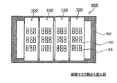
本開示の実施の形態に係るフレーム付き蒸着マスク200は、フレーム60に上記で説明した本開示の各実施の形態に係る蒸着マスク100が固定されてなる構成を呈している。蒸着マスク100についての説明は省略する。
(Deposition mask with frame)
The vapor deposition mask with
フレーム付き蒸着マスク200は、図10に示すように、フレーム60に、1つの蒸着マスク100が固定されたものであってもよく、図11に示すように、フレーム60に、複数の蒸着マスク100が固定されたものであってもよい。
The
例えば、図20に示すように、複数の蒸着マスクを一体化させた、1枚の蒸着マスク100をフレーム60に固定してもよい。なお、図20に示す形態では、長手方向に延びるそれぞれの金属層10の端部の全部或いは一部がフレームと接しており(図示する形態では全ての金属層10の長手方向の端部がフレーム60と接している)、蒸着マスク100の上辺、及び下辺近傍に配置されている金属層10のみならず、及び金属層10の端部の一部、或いは全部において、金属層10とフレームとが固定されている。なお、長手方向に延びる金属層10を、その端部とフレーム60とが接しない形態とし、蒸着マスク100とフレームとの固定を、蒸着マスク100の上辺、及び下辺近傍に配置されている金属層10との固定のみにより行うこともできる。
For example, as shown in FIG. 20, one
また、図21に示すように、3枚以上の蒸着マスク100を並べて配置してもよい(図示する形態では3枚の蒸着マスク)。この場合において、複数の蒸着マスク100は、それぞれ、隣り合う蒸着マスク100との間に隙間が生じないように配置してもよく、隙間をあけて配置してもよい(図21に示す形態では3つの蒸着マスクが隙間なく配置されている)。また、図21に示す形態では、フレームと固定される蒸着マスク100のうち、長手方向の両端に位置する蒸着マスク100の金属層10の端部は、フレームと接しない形態となっているが、長手方向の両端に位置する蒸着マスク100の金属層10の端部が、フレームと接する形態としてもよい(図示しない)。
Further, as shown in FIG. 21, three or
フレーム60は、略矩形形状の枠部材であり、最終的に固定される蒸着マスク100の樹脂マスク20に設けられた開口部25を蒸着源側に露出させるための貫通孔を有する。フレームの材料としては、金属材料や、ガラス材料、セラミック材料等を挙げることができる。
The
フレームの厚みについても特に限定はないが、剛性等の点から10mm以上100mm以下の範囲内であることが好ましく、10mm以上30mm以下の範囲内であることがより好ましい。フレームの開口の内周端面と、フレームの外周端面間の幅は、当該フレームと、蒸着マスクの金属層とを固定することができる幅であれば特に限定はなく、例えば、10mm以上300mm以下の範囲内や、10mm以上70mm以下の範囲内である。 The thickness of the frame is also not particularly limited, but is preferably in the range of 10 mm or more and 100 mm or less, and more preferably in the range of 10 mm or more and 30 mm or less from the viewpoint of rigidity or the like. The width between the inner peripheral end face of the opening of the frame and the outer peripheral end face of the frame is not particularly limited as long as the width of the frame and the metal layer of the evaporation mask can be fixed, and is, for example, 10 mm or more and 300 mm or less. It is in the range or in the range of 10 mm or more and 70 mm or less.
また、図12(a)〜(c)に示すように、フレームの貫通孔の領域に補強フレーム65等が設けられたフレーム60を用いてもよい。換言すれば、フレーム60が有する開口が、補強フレーム等によって分割された構成を有していてもよい。補強フレーム65を設けることで、当該補強フレーム65を利用して、フレーム60と蒸着マスク100とを固定することができる。具体的には、上記で説明した蒸着マスク100を縦方向、及び横方向に複数並べて固定するときに、当該補強フレームと蒸着マスクが重なる位置においても、フレーム60に蒸着マスク100を固定することができる。
Further, as shown in FIGS. 12A to 12C, a
フレーム60と、蒸着マスク100との固定方法についても特に限定はなく、レーザー光等により固定するスポット溶接、接着剤、ねじ止め、或いはこれ以外の方法を用いて固定することができる。
There is no particular limitation on the method of fixing the
<<蒸着マスク準備体>>
図13に示すように、本開示の実施の形態に係る蒸着マスク準備体150は、蒸着パターンを形成するために必要な開口部25を有する樹脂マスク20と、樹脂マスク20上に設けられた金属層10とを備える蒸着マスクを得るための蒸着マスク準備体150であって、樹脂板20A上に、金属層10が設けられた構成を呈している。そして、本開示の実施の形態に係る蒸着マスク準備体150は、樹脂板20Aが、樹脂材料を含有し、金属層10が、金属材料を含有しており、樹脂材料のガラス転移温度(Tg)に100℃を加算した温度を、上限温度としたときに、縦軸を線膨張の割合、横軸を温度とする線膨張曲線において、温度25℃から上限温度の範囲における樹脂板の線膨張曲線の積分値を、温度25℃から上限温度の範囲における金属層の線膨張曲線の積分値で除した値が、0.55以上1.45以下の範囲内に規定されている。
<< Evaporation mask preparation >>
As shown in FIG. 13, the
本開示の実施の形態に係る蒸着マスク準備体150によれば、樹脂板20Aに開口部25を形成するときに、樹脂板20Aに弛みや、シワ等が生ずること、また、樹脂板20Aに過剰にテンションがかかることを抑制することができ、寸法正確度や、位置正確度に優れ、また、寸法変動や、位置変動を抑制することができる開口部25を形成することができる。つまり、本開示の実施の形態に係る蒸着マスク準備体150によれば、正確度のよい開口部25を有し、且つ形成された開口部25に寸法変動や、位置変動が生ずることを抑制可能とする蒸着マスクを得ることができる。
According to vapor
本開示の実施の形態に係る蒸着マスク準備体150は、開口部25を有する樹脂マスク20を、樹脂板20Aとした以外は、全て、上記で説明した本開示の実施の形態に係る蒸着マスクと共通している。
The deposition
樹脂板20Aは、各種の塗工方法により得られる樹脂層であってもよく、シート状の樹脂板であってもよい。樹脂板20Aは最終的に樹脂マスク20となり、したがって、樹脂板20Aの厚みについては、最終的に得られる樹脂マスク20の厚みを考慮して決定すればよい。
The
<<蒸着マスクの製造方法>>
本開示の実施の形態に係る蒸着マスクの製造方法は、蒸着パターンを形成するために必要な開口部25を有する樹脂マスク20と、樹脂マスク20上に設けられる金属層10とを備える蒸着マスクの製造方法であって、金属材料を含む金属板10A上に、樹脂材料を含む樹脂板20Aを設ける工程(図14(a)参照)と、金属板10Aを加工して、樹脂板20A上に金属層10を形成する工程(図14(b)参照)と、樹脂板20Aに開口部25を形成する工程(図14(c)参照)と、を含み、樹脂材料のガラス転移温度(Tg)に100℃を加算した温度を、上限温度としたときに、縦軸を線膨張の割合、横軸を温度とする線膨張曲線において、温度25℃から上限温度の範囲における樹脂マスクの線膨張曲線の積分値を、温度25℃から上限温度の範囲における金属層の線膨張曲線の積分値で除した値が、0.55以上1.45以下の範囲内となるように、樹脂材料を含む樹脂板、及び金属材料を含有する金属板を用いる蒸着マスクの製造方法である。
<< Production method of evaporation mask >>
The method for manufacturing a deposition mask according to the embodiment of the present disclosure is directed to a method for manufacturing a deposition mask including a
また、本開示の別の実施の形態に係る蒸着マスクの製造方法は、蒸着パターンを形成するために必要な開口部25を有する樹脂マスク20と、樹脂マスク20上に設けられる金属層10とを備える蒸着マスクの製造方法であって、樹脂材料を含有する樹脂板20A上に、金属層10を設ける工程と、樹脂板20Aに蒸着パターンを形成するために必要な開口部25を形成する工程と、を含み、樹脂材料のガラス転移温度(Tg)に100℃を加算した温度を、上限温度としたときに、縦軸を線膨張の割合、横軸を温度とする線膨張曲線において、温度25℃から上限温度の範囲における樹脂マスクの線膨張曲線の積分値を、温度25℃から上限温度の範囲における金属層の線膨張曲線の積分値で除した値が、0.55以上1.45以下の範囲内となるように、樹脂材料を含む樹脂板、及び金属材料を含有する金属層を用いる蒸着マスクの製造方法である。
Further, the method for manufacturing a vapor deposition mask according to another embodiment of the present disclosure includes the steps of: forming a
本開示の各実施の形態に係る蒸着マスクの製造方法によれば、樹脂板20Aに開口部25を形成するときに、樹脂板20Aに弛みや、シワ等が生ずること、また、樹脂板20Aに過剰にテンションがかかることを抑制することができ、寸法正確度や、位置正確度に優れ、また、寸法変動や、位置変動を抑制することができる開口部25を形成することができる。つまり、本開示の実施の形態に係る蒸着マスクの製造方法によれば、正確度のよい開口部25を有し、且つ形成された開口部25に寸法変動や、位置変動が生ずることを抑制可能とする蒸着マスクを得ることができる。
According to the method for manufacturing a vapor deposition mask according to each embodiment of the present disclosure, when the
(金属板上に樹脂板を設ける工程)
本工程は、図14(a)に示すように、金属材料を含む金属板10A上に、樹脂板20Aを設ける工程である。
(Step of providing a resin plate on a metal plate)
This step is, as shown in FIG. 14A, a step of providing a
そして、本開示の実施の形態に係る蒸着マスクの製造方法では、樹脂材料のガラス転移温度(Tg)に100℃を加算した温度を、上限温度としたときに、縦軸を線膨張の割合、横軸を温度とする線膨張曲線において、温度25℃から上限温度の範囲における樹脂マスクの線膨張曲線の積分値を、温度25℃から上限温度の範囲における金属層の線膨張曲線の積分値で除した値が、0.55以上1.45以下の範囲内となるように、樹脂材料を含む樹脂板20A、及び金属材料を含有する金属板10Aを用いている。
In the method for manufacturing the evaporation mask according to the embodiment of the present disclosure, when the temperature obtained by adding 100 ° C. to the glass transition temperature (Tg) of the resin material is set as the upper limit temperature, the vertical axis represents the linear expansion ratio, In the linear expansion curve with the horizontal axis as temperature, the integral value of the linear expansion curve of the resin mask in the range of 25 ° C. to the upper limit temperature is calculated as the integral value of the linear expansion curve of the metal layer in the range of 25 ° C. to the upper limit temperature. The
樹脂板20Aは、予め成型されたものであってもよく、金属板10A上に、樹脂材料を含む塗工液を塗布、乾燥することで得られるものであってもよい。また、金属板10A上に接着層等を介して樹脂板20A(樹脂フィルム、樹脂シートであってもよい。)を貼り合せてもよい。なお、樹脂板20Aを形成するための塗工液は、樹脂材料と、当該樹脂材料を溶解させるための溶媒を含んでいる。塗工液の塗工方法について特に限定はなく、例えば、グラビア印刷法、スクリーン印刷法、グラビア版を用いたリバースロールコーティング法等の公知の手段を挙げることができる。塗工液の塗工量は、最終的に得られる樹脂マスク20の厚みに応じて適宜決定すればよい。
The
また、樹脂板20A上に、金属板10Aを、粘着層や、接着層を介して貼り合せてもよい。
Further, the
樹脂材料について特に限定はなく、上記本開示の実施の形態に係る蒸着マスクにおいて説明した樹脂マスク20に含まれる樹脂材料を適宜選択して用いることができる。例えば、熱硬化性樹脂の硬化物を含む樹脂板20Aとしてもよい。熱硬化性樹脂の硬化物を含む樹脂板20Aは、熱硬化性樹脂を含む塗工液を、金属板10A上に塗布し、これを熱硬化性樹脂の硬化温度を超える温度で加熱することで得ることができる。なお、熱硬化性樹脂の硬化温度は、樹脂板20Aが含有している熱硬化性樹脂に応じて適宜決定すればよい。なお、樹脂板20Aが、複数の熱硬化性樹脂を含有している場合には、複数の熱硬化性樹脂のうち、その硬化温度が最も高い熱硬化性樹脂の硬化温度を超える硬化温度で加熱を行うことが好ましい。
There is no particular limitation on the resin material, and the resin material included in the
(金属層を設ける工程)
本工程は、図14(b)に示すように、その表面に樹脂板20Aが形成された金属板10Aを加工して、金属層10を形成する工程である。図示する形態では、金属板10Aを加工して複数の貫通孔15を有する金属層10を形成しているが、1つの貫通孔15を有する金属層10や、複数の金属層10が部分的に位置するように加工してもよい。金属層10の形成方法について特に限定はなく、レーザー加工、エッチング加工、機械加工等の従来公知の加工法を用いて行うことができる。例えば、エッチング加工法を用いた金属層10の形成は、金属板10Aの表面に、レジスト材を塗工し、金属層10を形成するためのマスクを用いて当該レジスト材をマスキングし、露光、現像する。金属板10A、樹脂板20Aのそれぞれの表面にフォトレジスト材を塗布してもよい。また、フォトレジスト材の塗布にかえて、ドライフィルムレジストを貼り合せるドライフィルム法を用いることもできる。次いで、当該レジストパターンを耐エッチングマスクとして用いて、金属板10Aのみをエッチング加工し、エッチング終了後に前記レジストパターンを洗浄除去する。これにより、樹脂板20Aの所望の箇所に、金属層10を形成することができる。
(Step of providing a metal layer)
This step is, as shown in FIG. 14B, a step of forming a
上記金属板10Aを用いた金属層10の形成にかえて、めっき法により金属層10を形成することもできる。めっき法を用いた、一例としての樹脂板20A上への金属層10の形成方法は、各種のめっき法により、樹脂板20A上に金属層10を形成する方法である。他の一例としての形成方法は、ガラス基板などの支持体上に、各種のめっき法により金属層10を形成し、形成された金属層10と、樹脂板20Aとを貼り合わせ、その後、金属層10を、支持体から剥離して、樹脂板20A上に金属層10を形成する方法である。また、各種のめっき法により金属板を形成し、この金属板を加工して、金属層10を形成してもよい。
Instead of forming the
上記金属層を設ける工程において、金属板10Aを加工して、金属層10を形成する方法にかえて、樹脂板20A上に、予め準備された金属層10を設けてもよい。例えば、樹脂板20A上に、接着剤などを介して、予め準備された金属層10を貼り合せてもよい。
In the step of providing the metal layer, a
(開口部を形成する工程)
本工程は、図14(c)に示すように、樹脂材料を含む樹脂板20Aに、開口部25を形成する工程である。本工程を経ることで、蒸着パターンを形成するために必要な開口部25を有する樹脂マスク20と、樹脂マスク上に設けられた金属層10とを備える蒸着マスク100を得る。
(Step of forming an opening)
In this step, as shown in FIG. 14C, an
また、上記開口部20を形成する工程の後に、樹脂板20A上に、金属層10を設けてもよい。
After the step of forming the
開口部25の形成方法について特に限定はなく、レーザー加工法、エッチング加工法、機械加工法等の従来公知の加工法を用いて形成することができる。なお、レーザー加工法は、樹脂板20Aに、より正確度よく開口部25を形成することができる点で、好ましい加工法である。
The method for forming the
上記では、樹脂板20A上に、先に金属層10を形成し、その後、樹脂板20Aに開口部25を形成する例を中心に説明を行ったが、樹脂板20Aに開口部25を形成した後に、開口部25が形成された樹脂板20A(樹脂マスク20)上に、金属層10を形成してもよい。例えば、上記のめっき法を用いることで、金属板10Aの加工を行うことなく、開口部25を有する樹脂マスク20上に、選択的に金属層10を形成できる。なお、フレームに固定するときの、樹脂マスク20に形成された開口部の寸法の正確度や、位置変動を考慮すると、開口部25の形成は、フレームに樹脂板20Aを固定した後に行うことが好ましい。この場合、金属層10の形成は、フレームに固定された樹脂板20Aに対して行ってもよく、先に、樹脂板20A上に金属層10を形成し、金属層10が形成された樹脂板20Aをフレームに固定してもよい。また、樹脂板20Aと、金属板10Aとの積層体をフレームに固定し、或いは、フレームに固定された樹脂板20A上に、金属板10Aを設け、その後、樹脂板20Aに対する開口部25の形成や、金属板10Aに対する金属層10の形成を行ってもよい。
In the above description, the description has been made mainly of the example in which the
本開示の実施の形態に係る蒸着マスクの製造方法で製造される蒸着マスクとしては、上記で説明した本開示の各実施の形態に係る蒸着マスク等を挙げることができる。 Examples of the vapor deposition mask manufactured by the method of manufacturing a vapor deposition mask according to the embodiment of the present disclosure include the vapor deposition mask according to each embodiment of the present disclosure described above.
(蒸着マスクを用いた蒸着方法)
本開示の各実施の形態に係る蒸着マスクや、本開示の各実施の形態に係るフレーム付き蒸着マスクを用いた蒸着パターンの形成に用いられる蒸着方法については、特に限定はなく、例えば、反応性スパッタリング法、真空蒸着法、イオンプレーティング、電子ビーム蒸着法等の物理的気相成長法(Physical Vapor Deposition)、熱CVD、プラズマCVD、光CVD法等の化学気相成長法(Chemical Vapor Deposition)等を挙げることができる。また、蒸着パターンの形成は、従来公知の真空蒸着装置などを用いて行うことができる。
(Evaporation method using evaporation mask)
The vapor deposition mask according to each embodiment of the present disclosure, and the vapor deposition method used to form a vapor deposition pattern using the vapor deposition mask with a frame according to each embodiment of the present disclosure are not particularly limited, for example, reactive Physical vapor deposition such as sputtering, vacuum evaporation, ion plating, and electron beam evaporation, and chemical vapor deposition such as thermal CVD, plasma CVD, and photo-CVD (Chemical Vapor Deposition). And the like. Further, the formation of the vapor deposition pattern can be performed using a conventionally known vacuum vapor deposition apparatus or the like.
<<有機半導体素子の製造方法>>
次に、本開示の実施の形態に係る有機半導体素子の製造方法について説明する。本開示の有機半導体素子の製造方法は、蒸着マスクを用いて蒸着対象物に蒸着パターンを形成する蒸着パターン形成工程を含み、蒸着パターンを形成する工程において、上記で説明した本開示の各実施の形態に係る蒸着マスクが用いられる。
<<< Method of Manufacturing Organic Semiconductor Element >>>
Next, a method for manufacturing the organic semiconductor device according to the embodiment of the present disclosure will be described. The method for manufacturing an organic semiconductor device of the present disclosure includes a vapor deposition pattern forming step of forming a vapor deposition pattern on a vapor deposition target using a vapor deposition mask, and in the step of forming a vapor deposition pattern, each of the embodiments of the present disclosure described above. An evaporation mask according to the embodiment is used.
蒸着マスクを用いた蒸着法により蒸着パターンを形成する蒸着パターン形成工程について特に限定はなく、基板上に電極を形成する電極形成工程、有機層形成工程、対向電極形成工程、封止層形成工程等を有し、各任意の工程において、上記で説明した本開示の蒸着パターン形成方法を用いて、蒸着パターンが形成される。例えば、有機ELデバイスのR(レッド),G(グリーン),B(ブルー)各色の発光層形成工程に、上記で説明した本開示の蒸着パターン形成方法をそれぞれ適用する場合には、基板上に各色発光層の蒸着パターンが形成される。なお、本開示の有機半導体素子の製造方法は、これらの工程に限定されるものではなく、従来公知の有機半導体素子の製造における任意の工程に適用可能である。 There is no particular limitation on a vapor deposition pattern forming step of forming a vapor deposition pattern by a vapor deposition method using a vapor deposition mask, and an electrode forming step of forming an electrode on a substrate, an organic layer forming step, a counter electrode forming step, a sealing layer forming step, and the like. In each optional step, a vapor deposition pattern is formed using the vapor deposition pattern forming method of the present disclosure described above. For example, when the above-described vapor deposition pattern forming method of the present disclosure is applied to the light emitting layer forming process of each of R (red), G (green), and B (blue) of the organic EL device, a A vapor deposition pattern of each color light emitting layer is formed. The method of manufacturing an organic semiconductor device according to the present disclosure is not limited to these steps, and can be applied to any process in manufacturing a conventionally known organic semiconductor device.
以上説明した本開示の実施の形態に係る有機半導体素子の製造方法によれば、蒸着マスクと蒸着対象物とを隙間なく密着させた状態で、有機半導体素子を形成する蒸着を行うことができ、正確度よく有機半導体素子を製造することができる。本開示の有機半導体素子の製造方法で製造される有機半導体素子としては、例えば、有機EL素子の有機層、発光層や、カソード電極等を挙げることができる。特に、本開示の有機半導体素子の製造方法は、パターンの正確度が要求される有機ELデバイスのR(レッド),G(グリーン),B(ブルー)発光層の製造に好適に用いることができる。 According to the method for manufacturing an organic semiconductor element according to the embodiment of the present disclosure described above, in a state where the evaporation mask and the object to be evaporated are in close contact with each other without any gap, it is possible to perform evaporation for forming the organic semiconductor element, An organic semiconductor device can be manufactured with high accuracy. Examples of the organic semiconductor device manufactured by the method for manufacturing an organic semiconductor device according to the present disclosure include an organic layer, a light emitting layer, and a cathode electrode of an organic EL device. In particular, the method for manufacturing an organic semiconductor element of the present disclosure can be suitably used for manufacturing R (red), G (green), and B (blue) light emitting layers of an organic EL device that requires pattern accuracy. .
<<有機ELディスプレイの製造方法>>
次に、本開示の実施の形態に係る有機ELディスプレイ(有機エレクトロルミネッセンスディスプレイ)の製造方法について説明する。本開示の有機ELディスプレイの製造方法は、有機ELディスプレイの製造工程において、上記で説明した本開示の有機半導体素子の製造方法により製造された有機半導体素子が用いられる。
<< Manufacturing method of organic EL display >>
Next, a method for manufacturing an organic EL display (organic electroluminescence display) according to an embodiment of the present disclosure will be described. In the method of manufacturing an organic EL display according to the present disclosure, an organic semiconductor element manufactured by the above-described method of manufacturing an organic semiconductor element according to the present disclosure is used in a process of manufacturing an organic EL display.
上記本開示の有機半導体素子の製造方法により製造された有機半導体素子が用いられた有機ELディスプレイとしては、例えば、ノートパソコン(図15(a)参照)、タブレット端末(図15(b)参照)、携帯電話(図15(c)参照)、スマートフォン(図15(d)参照)、ビデオカメラ(図15(e)参照)、デジタルカメラ(図15(f)参照)、スマートウォッチ(図15(g)参照)等に用いられる有機ELディスプレイを挙げることができる。 Examples of the organic EL display using the organic semiconductor device manufactured by the method for manufacturing an organic semiconductor device according to the present disclosure include a notebook computer (see FIG. 15A) and a tablet terminal (see FIG. 15B). , A mobile phone (see FIG. 15 (c)), a smartphone (see FIG. 15 (d)), a video camera (see FIG. 15 (e)), a digital camera (see FIG. 15 (f)), a smart watch (see FIG. g), etc.).
(実施例および比較例)
金属板上に樹脂板を設けた蒸着マスク準備体サンプルA〜Iの9種類を準備した。蒸着マスク準備体サンプルA〜Iに対しては、予め、当該蒸着マスク準備体をなす金属板、樹脂板のCTE曲線を、上記の方法(線膨張曲線の作成方法)にて作成し、前述の積分値の算出により、算出された樹脂マスクの積分値を、算出された金属層の積分値で除して、比率を算出している。比率の算出結果を表1に示す。なお、表中の[樹脂板/金属板]は、各蒸着マスク準備体サンプルを構成する樹脂板、及び金属板における、温度25℃から上限温度の範囲における樹脂板の線膨張曲線の積分値を、温度25℃から上限温度の範囲における金属板の線膨張曲線の積分値で除した値を意味する。
(Examples and Comparative Examples)
Nine kinds of deposition mask preparation samples A to I each having a resin plate provided on a metal plate were prepared. For the deposition mask preparation samples A to I, the CTE curves of the metal plate and the resin plate forming the deposition mask preparation are prepared in advance by the above-described method (method of creating a linear expansion curve). By calculating the integral value, the ratio is calculated by dividing the calculated integral value of the resin mask by the calculated integral value of the metal layer. Table 1 shows the calculation results of the ratio. In the table, [resin plate / metal plate] represents the integral value of the linear expansion curve of the resin plate in the range of 25 ° C. to the upper limit temperature of the resin plate and the metal plate constituting each vapor deposition mask preparation sample. , A value obtained by dividing by an integral value of a linear expansion curve of a metal plate in a temperature range of 25 ° C. to an upper limit temperature.
各蒸着マスク準備体サンプルは、以下の方法により作成した。
(蒸着マスク準備体サンプルの作成)
厚みが20μm金属板を準備し、この金属板の一方の面に、ポリイミド樹脂の前駆体(ユピア(登録商標)ST 宇部興産(株))を、コンマコーターで塗布し、塗布後、130℃で120sec、次いで、160℃で160sec乾燥した。乾燥後、下表1に示す焼成条件(焼成温度、焼成時間)で、ポリイミド樹脂の前駆体の焼成処理を行い、金属板上に、厚みが5μmの樹脂板が形成されてなる各蒸着マスク準備体サンプル(蒸着マスク準備体サンプルA〜I)を得た。なお、焼成は、いずれも窒素雰囲気で行った。金属板は、Fe−36Ni合金(インバー材)を使用した。各蒸着マスク準備体サンプルにおける樹脂板(下表1の焼成条件による焼成後の樹脂板)は、ポリイミド樹脂の熱硬化物である。
Each deposition mask preparation sample was prepared by the following method.
(Preparation of sample for mask preparation for evaporation)
A metal plate having a thickness of 20 μm is prepared, and a polyimide resin precursor (UPIA (registered trademark) ST Ube Industries, Ltd.) is applied on one surface of the metal plate with a comma coater. After drying for 120 sec, then at 160 ° C. for 160 sec. After drying, the precursor of the polyimide resin is fired under the firing conditions (firing temperature and firing time) shown in Table 1 below to prepare each vapor deposition mask having a 5 μm thick resin plate formed on a metal plate. Body samples (evaporation mask preparation body samples A to I) were obtained. The firing was performed in a nitrogen atmosphere. The metal plate used was an Fe-36Ni alloy (invar material). The resin plate (resin plate after baking under the baking conditions in Table 1 below) in each vapor deposition mask preparation sample is a thermosetting polyimide resin.
上記で作成した各蒸着マスク準備体サンプルを、100mm(幅方向)×150mm(長手方向)のサイズにカットした。カットした各蒸着マスクサンプルの金属板を、特許第3440333号の実施例1に記載されている方法で、金属板側からエッチングし、金属板の中央部分に、当該金属板のみを貫通する70mm(幅方向)×120mm(長手方向)の貫通孔を1つ形成した。貫通孔を形成後の各蒸着マスク準備体サンプルについて、下記の評価方法に基づいて、(1)樹脂板に生じるシワの程度を評価した。次いで、貫通孔が形成された各蒸着マスク準備体サンプルの樹脂板に以下の方法で開口部を形成し、このときの(2)開口部の開口位置変動量を測定した。 Each of the prepared evaporation mask samples was cut into a size of 100 mm (width direction) × 150 mm (longitudinal direction). The cut metal plate of each vapor deposition mask sample is etched from the metal plate side by the method described in Example 1 of Japanese Patent No. 3440333, and the central portion of the metal plate is penetrated only with the metal plate by 70 mm ( One through hole of (width direction) × 120 mm (longitudinal direction) was formed. Based on the following evaluation method, (1) the degree of wrinkles generated on the resin plate was evaluated for each of the vapor deposition mask preparation samples after forming the through holes. Next, an opening was formed in the resin plate of each vapor deposition mask preparation sample in which the through hole was formed by the following method, and (2) the amount of change in the opening position of the opening at this time was measured.
(1)樹脂板のシワ評価
上記貫通孔を形成後の各蒸着マスク準備体サンプルについて、貫通孔と重なっている部分の樹脂板の状態を目視で確認し、下記の評価基準に基づいて、樹脂板のシワ評価を行った。評価結果を表1に示す。
(1) Evaluation of wrinkle of resin plate For each sample of the vapor deposition mask prepared after forming the through hole, the state of the resin plate in a portion overlapping with the through hole was visually checked, and the resin was evaluated based on the following evaluation criteria. The board was evaluated for wrinkles. Table 1 shows the evaluation results.
[評価基準]
A:樹脂板に目視で確認できるシワが生じていない。
B:樹脂板に目視で確認できるシワが僅かに生じている。
C:樹脂板に使用上問題となるシワが生じている。
[Evaluation criteria]
A: There is no wrinkle visible on the resin plate.
B: Wrinkles that can be visually confirmed are slightly generated on the resin plate.
C: The resin plate has wrinkles which are problematic in use.
(2)開口部の開口位置変動量の測定
上記シワ評価を行った各蒸着マスク準備体サンプルの樹脂板に対し、金属板側から、金属板に形成された貫通孔を通して、波長355nmのYAGレーザー(1J/cm2)にて、30μm×500μmの矩形パターンを樹脂板面に複数回照射し、樹脂板に縦横2列の開口部を形成した。長辺側のギャップは5μm、短辺側のギャップは50μmにした。その時の開口状態を顕微鏡にて観察した。片側のブリッジ部(短辺側のギャップ50μm)をレーザーにより切断した。この時の開口部の開口位置変動量を顕微鏡映像モニターに映して観察して、変動量の測定を行い以下の評価基準に基づいて評価した。評価結果を表1に示す。
[評価基準]
A:開口位置変動量が2μm以下。
B:開口位置変動量が2μmより大きく4μm未満。
C:開口位置変動量が4μm以上。
(2) Measurement of Variation of Opening Position of Opening A YAG laser having a wavelength of 355 nm was passed through the through-hole formed in the metal plate from the metal plate side to the resin plate of each vapor deposition mask preparation sample on which the wrinkle evaluation was performed. At (1 J / cm 2 ), a rectangular pattern of 30 μm × 500 μm was irradiated on the resin plate surface a plurality of times to form two rows of openings in the resin plate. The gap on the long side was 5 μm, and the gap on the short side was 50 μm. The opening state at that time was observed with a microscope. One side of the bridge portion (short side gap: 50 μm) was cut by a laser. The amount of change in the opening position of the opening at this time was projected on a microscope image monitor and observed, and the amount of change was measured and evaluated based on the following evaluation criteria. Table 1 shows the evaluation results.
[Evaluation criteria]
A: The opening position variation is 2 μm or less.
B: The opening position variation is larger than 2 μm and smaller than 4 μm.
C: The opening position variation is 4 μm or more.

10A…金属板
10…金属層
15…金属層の貫通孔
20A…樹脂板
20…樹脂マスク
25…開口部
60…フレーム
100…蒸着マスク
150…蒸着マスク準備体
10A: Metal plate 10: Metal layer 15: Metal layer through
Claims (20)
前記樹脂マスクは、蒸着パターンを形成するために必要な開口部を有し、
前記樹脂マスクは、樹脂材料を含有しており、
前記金属層は、金属材料を含有しており、
前記樹脂材料のガラス転移温度(Tg)に100℃を加算した温度を、上限温度としたときに、
縦軸を線膨張の割合、横軸を温度とする線膨張曲線において、温度25℃から前記上限温度の範囲における前記樹脂マスクの線膨張曲線の積分値を、温度25℃から前記上限温度の範囲における前記金属層の線膨張曲線の積分値で除した値が、0.55以上1.45以下の範囲内である、
蒸着マスク。 An evaporation mask in which a metal layer is provided on a resin mask,
The resin mask has an opening required to form a deposition pattern,
The resin mask contains a resin material,
The metal layer contains a metal material,
When the temperature obtained by adding 100 ° C. to the glass transition temperature (Tg) of the resin material is taken as the upper limit temperature,
In a linear expansion curve in which the vertical axis represents the ratio of linear expansion and the horizontal axis represents temperature, the integral value of the linear expansion curve of the resin mask in the range of 25 ° C. to the upper limit temperature is defined as the range of 25 ° C. to the upper limit temperature. The value obtained by dividing by the integral value of the linear expansion curve of the metal layer in the above is in the range of 0.55 or more and 1.45 or less.
Evaporation mask.
請求項1に記載の蒸着マスク。 The resin material is a cured product of a polyimide resin,
The vapor deposition mask according to claim 1.
請求項1又は2に記載の蒸着マスク。 The metal material is an iron alloy,
The vapor deposition mask according to claim 1.
請求項1乃至3の何れか1項に記載の蒸着マスク。 The vapor deposition mask according to claim 1.
請求項1乃至4の何れか1項に記載の蒸着マスク。 The vapor deposition mask according to claim 1.
請求項1乃至4の何れか1項に記載の蒸着マスク。 The vapor deposition mask according to claim 1.
請求項1乃至4の何れか1項に記載の蒸着マスク。 The vapor deposition mask according to claim 1.
前記蒸着マスクが、請求項1乃至7の何れか1項に記載の蒸着マスクである、 The vapor deposition mask is the vapor deposition mask according to any one of claims 1 to 7,
フレーム付き蒸着マスク。 Deposition mask with frame.
樹脂板上に金属層が設けられ、 A metal layer is provided on the resin plate,
前記樹脂板は、樹脂材料を含有しており、 The resin plate contains a resin material,
前記金属層は、金属材料を含有しており、 The metal layer contains a metal material,
前記樹脂材料のガラス転移温度(Tg)に100℃を加算した温度を、上限温度としたときに、 When the temperature obtained by adding 100 ° C. to the glass transition temperature (Tg) of the resin material is taken as the upper limit temperature,
縦軸を線膨張の割合、横軸を温度とする線膨張曲線において、温度25℃から前記上限温度の範囲における前記樹脂板の線膨張曲線の積分値を、温度25℃から前記上限温度の範囲における前記金属層の線膨張曲線の積分値で除した値が、0.55以上1.45以下の範囲内である、 In a linear expansion curve in which the vertical axis represents the ratio of linear expansion and the horizontal axis represents temperature, the integral value of the linear expansion curve of the resin plate in the range of the temperature of 25 ° C. to the upper limit temperature is defined as the range of the temperature of 25 ° C. to the upper limit temperature. The value obtained by dividing by the integral value of the linear expansion curve of the metal layer in the above is in the range of 0.55 or more and 1.45 or less.
蒸着マスク準備体。 Preparation body for evaporation mask.
請求項9に記載の蒸着マスク準備体。 A deposition mask preparation according to claim 9.
請求項9又は10に記載の蒸着マスク準備体。 The vapor deposition mask preparation according to claim 9 or 10.
請求項9乃至11の何れか1項に記載の蒸着マスク準備体。 The vapor deposition mask preparation according to claim 9.
樹脂材料を含有する樹脂板上に、金属材料を含有する金属層を設ける工程と、 A step of providing a metal layer containing a metal material on a resin plate containing a resin material,
前記樹脂板に、蒸着パターンを形成するために必要な開口部を形成する工程と、 A step of forming an opening necessary for forming a vapor deposition pattern on the resin plate,
を含み、 Including
前記樹脂材料のガラス転移温度(Tg)に100℃を加算した温度を、上限温度としたときに、 When the temperature obtained by adding 100 ° C. to the glass transition temperature (Tg) of the resin material is taken as the upper limit temperature,
縦軸を線膨張の割合、横軸を温度とする線膨張曲線において、温度25℃から前記上限 In a linear expansion curve in which the vertical axis represents the ratio of linear expansion and the horizontal axis represents temperature, the upper limit is set at 25 ° C.
温度の範囲における前記樹脂マスクの線膨張曲線の積分値を、温度25℃から前記上限温度の範囲における前記金属層の線膨張曲線の積分値で除した値が、0.55以上1.45以下の範囲内となるように、前記樹脂板上に前記金属層を設ける、The value obtained by dividing the integrated value of the linear expansion curve of the resin mask in the temperature range by the integrated value of the linear expansion curve of the metal layer in the range of the temperature from 25 ° C. to the upper limit temperature is 0.55 or more and 1.45 or less. Providing the metal layer on the resin plate so as to be within the range of
蒸着マスクの製造方法。 Manufacturing method of evaporation mask.
請求項13に記載の蒸着マスクの製造方法。 A method for manufacturing a deposition mask according to claim 13.
請求項13又は14に記載の蒸着マスクの製造方法。 A method for manufacturing a deposition mask according to claim 13.
請求項13乃至15の何れか1項に記載の蒸着マスクの製造方法。 A method for manufacturing a deposition mask according to claim 13.
請求項13乃至16の何れか1項に記載の蒸着マスクの製造方法。 A method for manufacturing a vapor deposition mask according to claim 13.
請求項1乃至7の何れか1項に記載の蒸着マスク、又は、請求項8に記載のフレーム付き蒸着マスクを用いる、 The vapor deposition mask according to any one of claims 1 to 7, or the vapor deposition mask with a frame according to claim 8,
有機半導体素子の製造方法。 A method for manufacturing an organic semiconductor device.
請求項18に記載の有機半導体素子の製造方法により製造された有機半導体素子を用いる、 Using an organic semiconductor device manufactured by the method for manufacturing an organic semiconductor device according to claim 18,
有機ELディスプレイの製造方法。 A method for manufacturing an organic EL display.
請求項1乃至7の何れか1項に記載の蒸着マスク、又は請求項8に記載のフレーム付き蒸着マスクを用いる、 The vapor deposition mask according to any one of claims 1 to 7, or the vapor deposition mask with a frame according to claim 8,
パターンの形成方法。 The method of forming the pattern.
Priority Applications (7)
| Application Number | Priority Date | Filing Date | Title |
|---|---|---|---|
| JP2018080690A JP6658790B2 (en) | 2018-04-19 | 2018-04-19 | Evaporation mask, evaporation mask with frame, evaporation mask preparation, method of manufacturing evaporation mask, method of manufacturing organic semiconductor element, method of manufacturing organic EL display, and method of forming pattern |
| US17/042,297 US20210013415A1 (en) | 2018-04-19 | 2019-03-20 | Vapor deposition mask, frame-equipped vapor deposition mask, vapor deposition mask preparation body, method of manufacturing vapor deposition mask, method of manufacturing organic semiconductor element, method of manufacturing organic el display, and method of forming pattern |
| PCT/JP2019/011768 WO2019202902A1 (en) | 2018-04-19 | 2019-03-20 | Vapor deposition mask, vapor deposition mask with frame, vapor deposition mask preparatory body, manufacturing method for vapor deposition mask, manufacturing method for organic semiconductor element, manufacturing method for organic el display, and pattern formation method |
| KR1020207026033A KR20200144091A (en) | 2018-04-19 | 2019-03-20 | Evaporation mask, evaporation mask with frame, evaporation mask preparation, evaporation mask manufacturing method, organic semiconductor device manufacturing method, organic EL display manufacturing method, and pattern formation method |
| CN202210638781.1A CN115110027B (en) | 2018-04-19 | 2019-03-20 | Evaporation mask and manufacturing method thereof |
| CN201980019365.XA CN111886357B (en) | 2018-04-19 | 2019-03-20 | Vapor deposition mask and manufacturing method thereof |
| TW108110610A TWI777055B (en) | 2018-04-19 | 2019-03-27 | Vapor deposition mask, vapor deposition mask with frame, vapor deposition mask preparation body, manufacturing method of vapor deposition mask, manufacturing method of organic semiconductor element, manufacturing method of organic EL display, and pattern formation method |
Applications Claiming Priority (1)
| Application Number | Priority Date | Filing Date | Title |
|---|---|---|---|
| JP2018080690A JP6658790B2 (en) | 2018-04-19 | 2018-04-19 | Evaporation mask, evaporation mask with frame, evaporation mask preparation, method of manufacturing evaporation mask, method of manufacturing organic semiconductor element, method of manufacturing organic EL display, and method of forming pattern |
Related Child Applications (1)
| Application Number | Title | Priority Date | Filing Date |
|---|---|---|---|
| JP2020018853A Division JP7120262B2 (en) | 2020-02-06 | 2020-02-06 | Method for manufacturing vapor deposition mask preparation, method for manufacturing framed vapor deposition mask preparation, and framed vapor deposition mask preparation |
Publications (3)
| Publication Number | Publication Date |
|---|---|
| JP2019189888A JP2019189888A (en) | 2019-10-31 |
| JP2019189888A5 JP2019189888A5 (en) | 2020-01-23 |
| JP6658790B2 true JP6658790B2 (en) | 2020-03-04 |
Family
ID=68240226
Family Applications (1)
| Application Number | Title | Priority Date | Filing Date |
|---|---|---|---|
| JP2018080690A Active JP6658790B2 (en) | 2018-04-19 | 2018-04-19 | Evaporation mask, evaporation mask with frame, evaporation mask preparation, method of manufacturing evaporation mask, method of manufacturing organic semiconductor element, method of manufacturing organic EL display, and method of forming pattern |
Country Status (6)
| Country | Link |
|---|---|
| US (1) | US20210013415A1 (en) |
| JP (1) | JP6658790B2 (en) |
| KR (1) | KR20200144091A (en) |
| CN (2) | CN115110027B (en) |
| TW (1) | TWI777055B (en) |
| WO (1) | WO2019202902A1 (en) |
Cited By (1)
| Publication number | Priority date | Publication date | Assignee | Title |
|---|---|---|---|---|
| TWI777614B (en) * | 2021-06-11 | 2022-09-11 | 達運精密工業股份有限公司 | Metal mask and method of manufacturing the same |
Families Citing this family (3)
| Publication number | Priority date | Publication date | Assignee | Title |
|---|---|---|---|---|
| KR20210091382A (en) * | 2020-01-13 | 2021-07-22 | 삼성디스플레이 주식회사 | Mask, method of manufacturing the same, and method of manufacturing display panel |
| KR20220056914A (en) * | 2020-10-28 | 2022-05-09 | 삼성디스플레이 주식회사 | Mask frame and deposition apparatus including the same |
| TWD215838S (en) | 2021-05-07 | 2021-12-01 | 景美科技股份有限公司 | Frame |
Family Cites Families (22)
| Publication number | Priority date | Publication date | Assignee | Title |
|---|---|---|---|---|
| US4916513A (en) * | 1965-09-28 | 1990-04-10 | Li Chou H | Dielectrically isolated integrated circuit structure |
| US5453293A (en) * | 1991-07-17 | 1995-09-26 | Beane; Alan F. | Methods of manufacturing coated particles having desired values of intrinsic properties and methods of applying the coated particles to objects |
| DE602004019835D1 (en) * | 2003-04-22 | 2009-04-23 | Asml Netherlands Bv | Carrier and method for producing a carrier |
| JP2010232163A (en) * | 2009-03-03 | 2010-10-14 | Fujifilm Corp | Method of manufacturing light-emitting display device, light-emitting display device, and light-emitting display |
| CN105331927B (en) | 2012-01-12 | 2018-09-11 | 大日本印刷株式会社 | Deposition mask prepares body |
| US10597766B2 (en) * | 2013-03-26 | 2020-03-24 | Dai Nippon Printing Co., Ltd. | Vapor deposition mask, vapor deposition mask preparation body, method for producing vapor deposition mask, and method for producing organic semiconductor element |
| JP6142388B2 (en) * | 2013-04-09 | 2017-06-07 | 株式会社ブイ・テクノロジー | Vapor deposition mask and vapor deposition mask manufacturing method |
| TWI661071B (en) * | 2013-04-12 | 2019-06-01 | 日商大日本印刷股份有限公司 | Vapor deposition mask, vapor deposition mask preparation body, method for manufacturing vapor deposition mask, method for forming pattern, and method for manufacturing organic semiconductor element |
| JP6078818B2 (en) * | 2013-07-02 | 2017-02-15 | 株式会社ブイ・テクノロジー | Film-forming mask and film-forming mask manufacturing method |
| JP6168944B2 (en) * | 2013-09-20 | 2017-07-26 | 株式会社ブイ・テクノロジー | Deposition mask |
| JP6229483B2 (en) * | 2013-12-24 | 2017-11-15 | コニカミノルタ株式会社 | Mask for film formation, mask film formation method, and method for manufacturing organic electroluminescence element |
| JP6620314B2 (en) * | 2014-03-25 | 2019-12-18 | パナソニックIpマネジメント株式会社 | Liquid resin composition, cured product, wiring structure, and mounting body using this wiring structure |
| JP6511908B2 (en) * | 2014-03-31 | 2019-05-15 | 大日本印刷株式会社 | Tension method of deposition mask, method of manufacturing deposition mask with frame, method of manufacturing organic semiconductor device, and tension device |
| KR102188493B1 (en) * | 2014-04-25 | 2020-12-09 | 삼성전자주식회사 | Method of growing nitride single crystal and method of manufacturing nitride semiconductor device |
| CN110306156A (en) * | 2014-06-06 | 2019-10-08 | 大日本印刷株式会社 | The manufacturing method of deposition mask and its precursor and organic semiconductor device |
| US10573815B2 (en) * | 2014-06-06 | 2020-02-25 | Dai Nippon Printing Co., Ltd. | Vapor deposition mask, frame-equipped vapor deposition mask, vapor deposition mask preparation body, and method for producing organic semiconductor element |
| JP6394879B2 (en) * | 2014-09-30 | 2018-09-26 | 大日本印刷株式会社 | Vapor deposition mask, vapor deposition mask preparation, framed vapor deposition mask, and organic semiconductor device manufacturing method |
| CN107075658B (en) * | 2014-10-23 | 2019-02-19 | 夏普株式会社 | The manufacturing method of deposition mask, deposition mask, evaporation coating device, evaporation coating method |
| CN113403574A (en) * | 2015-07-17 | 2021-09-17 | 凸版印刷株式会社 | Base material for metal mask and method for producing same, metal mask for vapor deposition and method for producing same |
| US11233199B2 (en) * | 2016-02-10 | 2022-01-25 | Hon Hai Precision Industry Co., Ltd. | Vapor deposition mask manufacturing method, vapor deposition mask, and organic semiconductor element manufacturing method |
| CN108779553B (en) * | 2016-03-23 | 2021-04-06 | 鸿海精密工业股份有限公司 | Vapor deposition mask, method for manufacturing same, and method for manufacturing organic semiconductor element |
| JP2018066053A (en) * | 2016-10-21 | 2018-04-26 | 大日本印刷株式会社 | Vapor deposition mask, vapor deposition mask with frame, vapor deposition mask preparation body, method of manufacturing vapor deposition mask, method of manufacturing organic semiconductor element, and method of manufacturing organic el television |
-
2018
- 2018-04-19 JP JP2018080690A patent/JP6658790B2/en active Active
-
2019
- 2019-03-20 US US17/042,297 patent/US20210013415A1/en active Pending
- 2019-03-20 CN CN202210638781.1A patent/CN115110027B/en active Active
- 2019-03-20 CN CN201980019365.XA patent/CN111886357B/en active Active
- 2019-03-20 WO PCT/JP2019/011768 patent/WO2019202902A1/en active Application Filing
- 2019-03-20 KR KR1020207026033A patent/KR20200144091A/en not_active Application Discontinuation
- 2019-03-27 TW TW108110610A patent/TWI777055B/en active
Cited By (1)
| Publication number | Priority date | Publication date | Assignee | Title |
|---|---|---|---|---|
| TWI777614B (en) * | 2021-06-11 | 2022-09-11 | 達運精密工業股份有限公司 | Metal mask and method of manufacturing the same |
Also Published As
| Publication number | Publication date |
|---|---|
| KR20200144091A (en) | 2020-12-28 |
| JP2019189888A (en) | 2019-10-31 |
| CN115110027B (en) | 2024-01-02 |
| WO2019202902A1 (en) | 2019-10-24 |
| TW202003884A (en) | 2020-01-16 |
| CN115110027A (en) | 2022-09-27 |
| TWI777055B (en) | 2022-09-11 |
| CN111886357B (en) | 2022-06-21 |
| CN111886357A (en) | 2020-11-03 |
| US20210013415A1 (en) | 2021-01-14 |
Similar Documents
| Publication | Publication Date | Title |
|---|---|---|
| JP6658790B2 (en) | Evaporation mask, evaporation mask with frame, evaporation mask preparation, method of manufacturing evaporation mask, method of manufacturing organic semiconductor element, method of manufacturing organic EL display, and method of forming pattern | |
| JP7024837B2 (en) | Manufacturing method of vapor deposition mask, vapor deposition mask preparation, vapor deposition mask preparation with frame, vapor deposition mask, vapor deposition mask with protective sheet, vapor deposition mask with frame-integrated protective sheet, manufacturing method of organic semiconductor element, and manufacturing of organic EL display Method | |
| TWI588277B (en) | Deposition mask | |
| JP2013227679A (en) | Vapor deposition mask manufacturing method and organic semiconductor element manufacturing method | |
| JP6642691B2 (en) | Frame-integrated vapor deposition mask, frame-integrated vapor deposition mask preparation, vapor deposition pattern forming method, organic semiconductor element manufacturing method, organic EL display manufacturing method | |
| JP6424521B2 (en) | Vapor deposition mask, vapor deposition mask with frame, and method of manufacturing organic semiconductor device | |
| JP6394877B2 (en) | Vapor deposition mask, vapor deposition mask manufacturing method, vapor deposition mask preparation, framed vapor deposition mask, and organic semiconductor element manufacturing method | |
| JP6326885B2 (en) | Vapor deposition mask, vapor deposition mask preparation, and method for manufacturing organic semiconductor element | |
| TW202006794A (en) | Mask and method for producing same | |
| JP2020037742A (en) | Vapor deposition mask, vapor deposition mask with frame, manufacturing method of organic semiconductor element, and manufacturing method of vapor deposition mask | |
| JP2015148002A (en) | Vapor deposition mask, vapor deposition mask preparation body, and manufacturing method for organic semiconductor device | |
| JP6347112B2 (en) | Vapor deposition mask, vapor deposition mask preparation, vapor deposition mask manufacturing method, pattern manufacturing method, framed vapor deposition mask, and organic semiconductor element manufacturing method | |
| JP7120262B2 (en) | Method for manufacturing vapor deposition mask preparation, method for manufacturing framed vapor deposition mask preparation, and framed vapor deposition mask preparation | |
| JP2018066053A (en) | Vapor deposition mask, vapor deposition mask with frame, vapor deposition mask preparation body, method of manufacturing vapor deposition mask, method of manufacturing organic semiconductor element, and method of manufacturing organic el television | |
| JP6879461B2 (en) | Thin-film mask, thin-film mask with frame, thin-film mask preparation, method for manufacturing organic semiconductor elements, and method for manufacturing organic EL display | |
| JP7127281B2 (en) | Deposition mask, framed deposition mask, deposition mask preparation, pattern forming method, deposition mask manufacturing method, organic semiconductor element manufacturing method, and organic EL display manufacturing method | |
| JP7340160B2 (en) | Vapor deposition mask manufacturing method and vapor deposition mask | |
| JP6645534B2 (en) | Deposition mask with frame | |
| JP2016106180A (en) | Method for manufacturing vapor deposition mask | |
| JP2018059139A (en) | Method for manufacturing vapor deposition mask, method for manufacturing organic semiconductor element and method for manufacturing organic electroluminescence display | |
| JP2016106179A (en) | Vapor deposition mask, vapor deposition mask with frame, and method for manufacturing organic electroluminescent element | |
| JP2017066533A (en) | Method for manufacturing vapor deposition mask | |
| JP2017145509A (en) | Vapor deposition mask, vapor deposition mask with frame, and method for manufacturing organic electroluminescent element |
Legal Events
| Date | Code | Title | Description |
|---|---|---|---|
| A521 | Request for written amendment filed |
Free format text: JAPANESE INTERMEDIATE CODE: A523 Effective date: 20191202 |
|
| A621 | Written request for application examination |
Free format text: JAPANESE INTERMEDIATE CODE: A621 Effective date: 20191202 |
|
| A871 | Explanation of circumstances concerning accelerated examination |
Free format text: JAPANESE INTERMEDIATE CODE: A871 Effective date: 20191202 |
|
| A975 | Report on accelerated examination |
Free format text: JAPANESE INTERMEDIATE CODE: A971005 Effective date: 20191223 |
|
| TRDD | Decision of grant or rejection written | ||
| A01 | Written decision to grant a patent or to grant a registration (utility model) |
Free format text: JAPANESE INTERMEDIATE CODE: A01 Effective date: 20200107 |
|
| A61 | First payment of annual fees (during grant procedure) |
Free format text: JAPANESE INTERMEDIATE CODE: A61 Effective date: 20200120 |
|
| R150 | Certificate of patent or registration of utility model |
Ref document number: 6658790 Country of ref document: JP Free format text: JAPANESE INTERMEDIATE CODE: R150 |