JP6657774B2 - Saddle-type vehicle - Google Patents
Saddle-type vehicle Download PDFInfo
- Publication number
- JP6657774B2 JP6657774B2 JP2015210461A JP2015210461A JP6657774B2 JP 6657774 B2 JP6657774 B2 JP 6657774B2 JP 2015210461 A JP2015210461 A JP 2015210461A JP 2015210461 A JP2015210461 A JP 2015210461A JP 6657774 B2 JP6657774 B2 JP 6657774B2
- Authority
- JP
- Japan
- Prior art keywords
- cooling water
- radiator
- engine
- water injection
- type vehicle
- Prior art date
- Legal status (The legal status is an assumption and is not a legal conclusion. Google has not performed a legal analysis and makes no representation as to the accuracy of the status listed.)
- Active
Links
Images


Description
本発明は、水冷式エンジンを備えた鞍乗型車両に関する。 The present invention relates to a straddle-type vehicle provided with a water-cooled engine.
一般に、水冷式エンジンを搭載した鞍乗型車両は、冷却水を吐出するウォータポンプと、エンジン内に冷却水を流通させてエンジンを冷却するウォータジャケットと、エンジンを冷却した後の冷却水を走行風または電動ファンにより冷却するラジエータ等を備えている。 In general, a saddle-ride type vehicle equipped with a water-cooled engine has a water pump that discharges cooling water, a water jacket that circulates cooling water inside the engine to cool the engine, and runs the cooling water after cooling the engine. A radiator for cooling by wind or an electric fan is provided.
また、このような鞍乗型車両には、ウォータポンプ、ウォータジャケットおよびラジエータ等を配管等により接続することにより冷却水経路が形成され、さらに、この冷却水経路内に冷却水を注入する冷却水注水口が設けられている。 Further, in such a saddle-ride type vehicle, a cooling water path is formed by connecting a water pump, a water jacket, a radiator, and the like with piping and the like, and a cooling water path for injecting cooling water into the cooling water path. A water inlet is provided.
従来の多くの鞍乗型車両において、冷却水注水口はラジエータの左端部または右端部の上部に形成され、冷却水注水口にはラジエータキャップが取り付けられている。また、従来の鞍乗型車両の中には、例えば特許文献1に記載されているように、冷却水注水口がエンジンの上方に配置されているものもある。 In many conventional straddle-type vehicles, a cooling water injection port is formed at an upper portion of a left end or a right end of a radiator, and a radiator cap is attached to the cooling water injection port. Further, in some conventional saddle-ride type vehicles, as described in Patent Literature 1, for example, a cooling water inlet is disposed above an engine.
例えば、鞍乗型車両の整備時に冷却水を交換するとき、整備作業者は冷却水注水口から冷却水を注入する。なお、鞍乗型車両の日常的な簡易な整備において少量の冷却水を補充する場合には、このような冷却水注水口ではなく、例えばリザーバタンクに設けられた別の注水口から冷却水を補充する。 For example, when replacing cooling water during maintenance of a saddle-ride type vehicle, a maintenance worker injects cooling water from a cooling water inlet. When replenishing a small amount of cooling water in daily simple maintenance of a saddle type vehicle, instead of such a cooling water injection port, for example, the cooling water is supplied from another injection port provided in a reservoir tank. refill.
ところで、冷却水注水口は、整備作業者による冷却水の注入を容易にするために、簡単な作業によって冷却水注水口を外部に露出させることが可能な位置に配置することが望まれる。また、冷却水注水口の位置は、当該冷却水注水口からの冷却水の注入により冷却水経路内に冷却水を充填することが可能となるように、冷却水経路の最も高い位置またはそれよりも高い位置に設定する必要がある。 By the way, in order to make it easy for a maintenance worker to inject the cooling water, it is desired that the cooling water injection port be disposed at a position where the cooling water injection port can be exposed to the outside by a simple operation. Further, the position of the cooling water inlet is set at the highest position of the cooling water path or higher than the highest position so that the cooling water can be filled in the cooling water path by injecting the cooling water from the cooling water inlet. Also need to be set at a higher position.
この点、冷却水注水口がラジエータの左端部または右端部の上部に形成されている構成によれば、整備作業者はラジエータキャップを取り外すだけの簡単な作業によって冷却水注水口を外部に露出させることができる。 In this regard, according to the configuration in which the cooling water inlet is formed at the upper part of the left end or the right end of the radiator, the maintenance worker exposes the cooling water inlet to the outside by a simple operation of simply removing the radiator cap. be able to.
しかしながら、この構成は、冷却水の配管がエンジン上方等、ラジエータよりも高い位置に配置されている鞍乗型車両には採用することができない。すなわち、この構成では、冷却水注水口がラジエータに一体形成されているため、冷却水経路の一部がラジエータよりも高い位置に配置されている鞍乗型車両においては、冷却水注水口の位置を冷却水経路の最も高い位置またはそれよりも高い位置に設定することができない。 However, this configuration cannot be applied to a straddle-type vehicle in which the cooling water pipe is disposed at a position higher than the radiator, such as above the engine. That is, in this configuration, since the cooling water injection port is formed integrally with the radiator, in a saddle-ride type vehicle in which a part of the cooling water path is disposed at a position higher than the radiator, the position of the cooling water injection port is Cannot be set at the highest position or higher in the cooling water path.
一方、特許文献1に記載の鞍乗型車両のように、冷却水注水口がエンジン上方に配置されている構成によれば、整備作業者は燃料タンクを取り外した後、冷却水注水口に取り付けられたキャップを取り外すことで、冷却水注水口を外部に露出させることができる。燃料タンクを取り外す作業を要するものの、燃料タンクは比較的着脱が容易であるため、この構成によれば、簡単な作業によって冷却水注水口を外部に露出させることができるといえる。 On the other hand, according to the configuration in which the cooling water inlet is disposed above the engine as in the saddle riding type vehicle described in Patent Document 1, the maintenance worker removes the fuel tank and then attaches the fuel tank to the cooling water inlet. By removing the cap provided, the cooling water inlet can be exposed to the outside. Although the operation of removing the fuel tank is required, the attachment and detachment of the fuel tank is relatively easy. Therefore, according to this configuration, it can be said that the cooling water injection port can be exposed to the outside by a simple operation.
また、この構成は、冷却水の配管がエンジン上方等、ラジエータよりも高い位置に配置されている鞍乗型車両にも採用することができる。すなわち、この構成では、冷却水注水口がエンジン上方に配置されているため、冷却水経路の一部がラジエータよりも高い位置に配置されている鞍乗型車両においても、冷却水注水口の位置を冷却水経路の最も高い位置またはそれよりも高い位置に容易に設定することができる。 This configuration can also be adopted in a straddle-type vehicle in which a cooling water pipe is arranged at a position higher than a radiator, such as above an engine. That is, in this configuration, since the cooling water injection port is disposed above the engine, the position of the cooling water injection port can be set even in a straddle-type vehicle in which a part of the cooling water path is disposed at a position higher than the radiator. Can be easily set at the highest position or higher in the cooling water path.
しかしながら、この構成は、エンジン上方に例えばエアクリーナ等の部品が配置されている鞍乗型車両には採用し難い。すなわち、エンジン上方にエアクリーナ等の部品が配置されている場合、エンジン上方に空きスペースが少なく、エンジン上方に冷却水注水口を配置するスペースを確保することが困難である。また、エンジンの上面と、エンジンの上方に配置されたエアクリーナ等の部品との間の空間に冷却水注水口を配置した場合には、冷却水注入時に冷却水注水口を露出させるために、燃料タンクだけでなくエアクリーナ等の部品をも取り外さなければならない。この結果、冷却水注水口を露出させて冷却水を注入する作業を行う際に、工数の多い複雑な作業を整備作業者に要求することとなる。 However, this configuration is difficult to employ in a straddle-type vehicle in which components such as an air cleaner are arranged above the engine. That is, when components such as an air cleaner are arranged above the engine, there is little empty space above the engine, and it is difficult to secure a space for disposing the cooling water inlet above the engine. Further, when the cooling water inlet is disposed in a space between the upper surface of the engine and a component such as an air cleaner disposed above the engine, the fuel injection hole is exposed when the cooling water is injected. Parts such as air cleaners as well as tanks must be removed. As a result, when performing the work of injecting the cooling water by exposing the cooling water inlet, the maintenance worker is required to perform a complicated work with many man-hours.
他方、冷却水注水口を、ラジエータおよびエンジンよりも高い位置であって、エンジンの左側または右側に配置する構成が考えられる。この構成によれば、整備作業者は簡単な作業によって冷却水注水口を外部に露出させることができ、また、冷却水経路の一部がエンジン上方等、ラジエータよりも高い位置に配置されている場合でも冷却水注水口の位置を冷却水経路の最も高い位置またはそれよりも高い位置に設定することができ、また、エンジン上方にエアクリーナ等の部品が配置されていても、支障なく、冷却水注水口を配置することができる。 On the other hand, a configuration is conceivable in which the cooling water inlet is located at a position higher than the radiator and the engine and on the left or right side of the engine. According to this configuration, the maintenance worker can expose the cooling water injection port to the outside by a simple operation, and a part of the cooling water path is arranged at a position higher than the radiator, such as above the engine. Even in this case, the position of the cooling water inlet can be set at the highest position or higher in the cooling water path, and even if components such as an air cleaner are placed above the engine, there is no problem. A water inlet can be placed.
しかしながら、この構成の場合、鞍乗型車両の車幅が大きくなり、鞍乗型車両のハンドリング性を低下させる等の問題が生じるおそれがある。 However, in the case of this configuration, the width of the saddle-ride type vehicle becomes large, and there is a possibility that a problem such as a decrease in the handleability of the saddle-ride type vehicle occurs.
本発明は例えば上述したような問題に鑑みなされたものであり、本発明の課題は、冷却水経路の一部がラジエータおよびエンジンよりも高い位置に配置され、かつエンジン上方にエアクリーナ等の部品が配置されている場合であっても、冷却水注水口を、外部に容易に露出させることができ、かつ冷却水経路の最も高い位置またはそれよりも高い位置に配置することができると共に、車幅を小さくすることができる鞍乗型車両を提供することにある。 The present invention has been made in consideration of, for example, the above-described problems, and an object of the present invention is to arrange a part of a cooling water path at a position higher than a radiator and an engine, and to install a component such as an air cleaner above the engine. Even if it is arranged, the cooling water inlet can be easily exposed to the outside and can be arranged at the highest position or higher in the cooling water path, and the vehicle width can be reduced. It is an object of the present invention to provide a straddle-type vehicle capable of reducing the size of the vehicle.
上記課題を解決するために、本発明の鞍乗型車両は、ヘッドパイプ、および前記ヘッドパイプに接続され、前記ヘッドパイプから車幅方向の一側および他側にそれぞれ拡開しつつ後方へ伸長する一対のメインフレームを有する車体フレームと、前記一対のメインフレーム間に支持されたエンジンと、前記エンジンに設けられ、冷却水を吐出するウォータポンプと、前記エンジンの前方に設けられ、冷却水を冷却するラジエータと、前記ウォータポンプから吐出された冷却水が前記エンジンおよび前記ラジエータを流通して前記ウォータポンプへ戻るように当該冷却水を循環させる冷却水経路と、前記冷却水経路に冷却水を注入する注水口を有し、前記ラジエータから分離した注水部と、前記ラジエータに設けられた冷却水供給口と前記注水部との間を接続する注水配管とを備え、前記注水部は、前記エンジンおよび前記ラジエータよりも高い位置であって、車幅方向において中心よりも一側であり、前記一対のメインフレーム間の外側であり、かつ車幅方向において前記ラジエータの一側端部よりも内側である位置に配置され、前記ラジエータは当該ラジエータの下部が当該ラジエータの上部よりも後方に位置するように傾斜しており、前記冷却水供給口は前記ラジエータの車幅方向一側部分の後面の下部において前記エンジンのシリンダヘッドカバーよりも下方に位置する部分に配置され、前記注水配管は、前記冷却水供給口と前記注水部との間を上下方向に略直線状に伸長していることを特徴とする。 In order to solve the above problem, a saddle-ride type vehicle according to the present invention is connected to a head pipe and the head pipe, and extends rearward while expanding from the head pipe to one side and the other side in the vehicle width direction. A body frame having a pair of main frames, an engine supported between the pair of main frames, a water pump provided on the engine, for discharging cooling water, and a water pump provided in front of the engine to supply cooling water. A radiator for cooling, a cooling water path for circulating the cooling water such that cooling water discharged from the water pump flows through the engine and the radiator and returns to the water pump, and a cooling water path for the cooling water path. A water injection part having a water injection port for injection, separated from the radiator, a cooling water supply port provided in the radiator and A water injection pipe connecting between the engine and the radiator, at a position higher than the engine and the radiator, one side of the center in the vehicle width direction, and at an outer side between the pair of main frames. And is disposed at a position inside one end of the radiator in the vehicle width direction, the radiator is inclined such that a lower portion of the radiator is located rearward of an upper portion of the radiator, The cooling water supply port is disposed at a portion located below the cylinder head cover of the engine at a lower portion of the rear surface of the radiator on one side in the vehicle width direction, and the water supply pipe is provided with the cooling water supply port, the water supply section, The space extends substantially linearly in the vertical direction.
本発明のこの態様によれば、注水口を有する注水部は、一対のメインフレーム間の外側に配置されており、一対のメインフレーム間の内側に配置されているエンジンの上方から外れた場所に位置している。したがって、エンジン上方にエアクリーナ等の部品が配置されている場合でも、これらの部品により注水口の上方が遮られることがない。また、このような位置に注水部が配置されているので、注水口の上方に空間を形成することが容易になる。それゆえ、整備作業者は、冷却水注入時に、注水口を外部に容易に露出させることができ、冷却水を注水口に簡単に注入することができる。また、注水部が、車幅方向において、中心よりも一側であって、ラジエータの一側端部よりも内側に配置されているので、鞍乗型車両の車幅を小さくすることができる。また、注水部がエンジンおよびラジエータよりも高い位置に配置されているので、冷却水経路の一部がエンジンおよびラジエータよりも高い位置に配置されている場合であっても、注水口の位置を冷却水経路の最も高い位置またはそれよりも高い位置に設定することができる。 According to this aspect of the present invention, the water injection portion having the water injection port is disposed outside the pair of main frames, and at a location separated from above the engine disposed inside the pair of main frames. positioned. Therefore, even when components such as an air cleaner are arranged above the engine, the components above the water inlet are not obstructed. Further, since the water injection section is disposed at such a position, it is easy to form a space above the water injection port. Therefore, the maintenance worker can easily expose the water injection port to the outside when injecting the cooling water, and can easily inject the cooling water into the water injection port. Further, since the water injection section is disposed on one side of the center and inside of one end of the radiator in the vehicle width direction, the vehicle width of the straddle-type vehicle can be reduced. Further, since the water injection section is arranged at a position higher than the engine and the radiator, even when a part of the cooling water path is arranged at a position higher than the engine and the radiator, the position of the water injection port is cooled. It can be set at the highest position or higher in the water path.
また、上述した本発明の鞍乗型車両において、前記冷却水経路の途中に接続され、前記冷却水経路を循環する冷却水の温度に応じて前記ラジエータを流通する冷却水の量を制御するサーモスタットを有するサーモスタットハウジングを備え、前記サーモスタットハウジングは前記エンジンの上方に配置され、前記注水部は前記サーモスタットハウジングよりも高い位置に配置されていることが好ましい。 Further, in the saddle-ride type vehicle of the present invention described above, a thermostat connected in the middle of the cooling water path and controlling an amount of cooling water flowing through the radiator according to a temperature of the cooling water circulating in the cooling water path. It is preferable that the thermostat housing is provided above the engine, and the water injection section is disposed at a position higher than the thermostat housing.
本発明のこの態様によれば、冷却水経路の途中に接続されたサーモスタットハウジングがエンジンの上方に配置されている場合であっても、このサーモスタットハウジングよりも高い位置に注水部が配置されているので、注水口の位置を冷却水経路の最も高い位置またはそれよりも高い位置に設定することができる。 According to this aspect of the present invention, even when the thermostat housing connected in the middle of the cooling water path is arranged above the engine, the water injection section is arranged at a position higher than the thermostat housing. Therefore, the position of the water inlet can be set to the highest position of the cooling water path or a position higher than the highest position.
また、上述した本発明の鞍乗型車両において、前記注水部は前記サーモスタットハウジングよりも車幅方向外側に配置されていることが好ましい。 Further, in the saddle-ride type vehicle of the present invention described above, it is preferable that the water injection section is disposed outside the thermostat housing in the vehicle width direction.
本発明のこの態様によれば、注水部が、エンジンの上方に配置されたサーモスタットハウジングよりも車幅方向外側に配置されているので、エンジン上方(サーモスタットハウジングの上方)にエアクリーナ等の部品が配置されている場合でも、これらの部品により注水口の上方が遮られることがない。 According to this aspect of the present invention, since the water injection section is arranged outside the thermostat housing arranged above the engine in the vehicle width direction, parts such as the air cleaner are arranged above the engine (above the thermostat housing). In this case, these parts do not block the water inlet.
また、上述した本発明の鞍乗型車両において、前記注水部は、当該鞍乗型車両の上面視において、前記ラジエータの上端部に沿って車幅方向に伸長する直線と、前記一対のメインフレームのうち車幅方向一側のメインフレームの前端部に沿って伸長する直線と、前記ラジエータにおける車幅方向一側の上隅部を通って前記鞍乗型車両の前後方向に伸長する直線とにより囲まれた三角形の領域内の略中央に配置されていることが好ましい。 Further, in the saddle-ride type vehicle of the present invention described above, the water injection portion includes a straight line extending in a vehicle width direction along an upper end portion of the radiator in a top view of the saddle-ride type vehicle, and the pair of main frames. A straight line extending along the front end of the main frame on one side in the vehicle width direction and a straight line extending in the front-rear direction of the saddle-ride type vehicle through an upper corner on one side in the vehicle width direction of the radiator. it is not preferable disposed substantially at the center of the area of the triangle enclosed.
本発明のこの態様によれば、注水部の位置が、エンジンの上方から外れた位置となるので、エンジン上方にエアクリーナ等の部品が配置されている場合でも、これらの部品により注水口の上方が遮られることを防止することができる。また、注水部の位置が、一対のメインフレーム間の外側となるので、整備作業者は、冷却水注入時に注水口を外部に容易に露出させることができ、注水口に容易にアクセスすることができる。また、注水部の位置が、車幅方向においてラジエータの一側端部よりも内側となるので、鞍乗型車両の車幅を小さくすることができる。 According to this aspect of the present invention, the position of the water injection portion is a position deviated from above the engine. Therefore, even when components such as the air cleaner are arranged above the engine, these components cause the upper portion of the water inlet to be above. It can be prevented from being blocked. Further, since the position of the water injection portion is located outside the pair of main frames, the maintenance worker can easily expose the water injection port to the outside at the time of cooling water injection, and can easily access the water injection port. it can. Further, since the position of the water injection portion is located inside one end of the radiator in the vehicle width direction, the vehicle width of the saddle type vehicle can be reduced.
本発明によれば、鞍乗型車両において、冷却水経路の一部がラジエータおよびエンジンよりも高い位置に配置され、かつエンジン上方にエアクリーナ等の部品が配置されている場合であっても、冷却水注水口を、外部に容易に露出させることができ、かつ冷却水経路の最も高い位置またはそれよりも高い位置に配置することができると共に、車幅を小さくすることができる。 According to the present invention, in a straddle-type vehicle, even if a part of the cooling water path is arranged at a position higher than the radiator and the engine and components such as an air cleaner are arranged above the engine, The water inlet can be easily exposed to the outside, can be arranged at the highest position or higher in the cooling water path, and the vehicle width can be reduced.
(過給機付き自動二輪車)
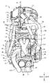
図1は本発明の鞍乗型車両の実施形態である過給機付き自動二輪車を示している。図1では、説明の便宜上、過給機付き自動二輪車の車体フレーム211およびエンジンユニット11以外の部分を二点鎖線で示している。また、図2ないし図5は車体フレーム211およびエンジンユニット11の正面図、左側面図、右側面図および平面図であり、図6はエンジンユニット11からラジエータ33を取り除いた状態を示す正面図である。また、図7はエンジンユニット11からエアクリーナ111、インタークーラ117およびサージタンク119を取り除いた状態を示す平面図である。また、以下の実施形態の説明において、前、後、左、右、上および下の方向は、過給機付き自動二輪車のシートに座した運転者を基準とする。
(Motorcycle with supercharger)
FIG. 1 shows a motorcycle with a supercharger, which is an embodiment of a straddle-type vehicle according to the present invention. In FIG. 1, for convenience of description, portions other than the
図1において、本発明の鞍乗型車両の実施形態である過給機付き自動二輪車1の車体フレーム211は、例えば複数の鋼鉄製パイプを接合することにより形成されている。具体的には、車体フレーム211は、自動二輪車1の前部上側に配置されたヘッドパイプ212と、自動二輪車1の左部および右部にそれぞれ配置され、前端部がヘッドパイプ212の上部に接続され、後端側が下方に傾斜しつつ後方へ伸長する一対のメインフレーム213と、自動二輪車1の左部および右部にそれぞれ配置され、前端部がヘッドパイプ212の下部に接続され、後端側がメインフレーム213よりも大きく下方に傾斜しつつ後方へ伸長する一対のダウンチューブ214と、自動二輪車1の左部および右部にそれぞれ配置され、前端部がダウンチューブ214の中間部にそれぞれ接続され、後端側が後方へ伸長する一対のサイドフレーム215と、メインフレーム213の後端側にそれぞれ接合された一対のピボットフレーム216とを備えている。また、メインフレーム213、ダウンチューブ214およびサイドフレーム215間には補強フレーム217が設けられている。
In FIG. 1, a
また、図5に示すように、一対のメインフレーム213はヘッドパイプ212から左、右にそれぞれ拡開しつつ後方へ伸長している。すなわち、自動二輪車1の左右方向(車幅方向)の中心を自動二輪車1の前後方向に貫く直線を基準線Sとすると、右側のメインフレーム213の前端部は、自動二輪車1の左右方向の中心に配置されたヘッドパイプ212から、右後方に斜めに伸長している。その後、この右側のメインフレーム213は、エンジン12のシリンダヘッド15の後部右方付近で緩やかに湾曲した後、基準線Sと平行に後方へ伸長している。その後、この右側のメインフレーム213は、シリンダヘッド15の後面を超えた付近で僅かに湾曲し、基準線Sに徐々に接近するように若干左方に傾斜しつつ後方へ伸長している。また、この右側のメインフレーム213は、シリンダヘッド15の後部右方付近で最も右に膨らむが、その位置における当該右側のメインフレーム213の右面(外側面)の左右方向の位置は、上ラジエータ34の右端部の位置と等しいか、それよりも左側(内側)である。なお、図5中の基準線Hは、右側のメインフレーム213における最も右に膨らんだ部分の右面の左右方向の位置を示している。また、図5中の基準線Eは上ラジエータ34の右端部の位置を示している。一方、左側のメインフレーム213は、基準線Sを基準として、右側のメインフレーム213と略左右対称の形状を有している。また、一対のダウンチューブ214も、一対のメインフレーム213とほぼ同様に、ヘッドパイプ212から左、右にそれぞれ拡開しつつ後方へ伸長している。
As shown in FIG. 5, the pair of
また、図1に示すように、ヘッドパイプ212には、ステアリングシャフト(図示せず)が挿入され、ステアリングシャフトの上端部および下端部にはそれぞれステアリングブラケット225が設けられている。また、上側のステアリングブラケット225にはハンドル226が設けられている。また、上側および下側のステアリングブラケット225には左右一対のフロントフォーク227の上部がそれぞれ支持され、これらフロントフォーク227の下端側には前輪228が支持されている。
As shown in FIG. 1, a steering shaft (not shown) is inserted into the
また、左右一対のピボットフレーム216間にはピボット軸231を介してスイングアーム232の前端側が支持され、スイングアーム232の後端側には後輪233が支持されている。また、後輪233の車軸にはドリブンスプロケット234が設けられ、ドリブンスプロケット234には、後述するエンジン12の動力を伝達するチェーン235が巻回されている。
A front end of the
また、自動二輪車1の前輪228と後輪233との間にはエンジンユニット11が設けられている。エンジンユニット11は、主に、左側のメインフレーム213および左側のダウンチューブ214と、右側のメインフレーム213および右側のダウンチューブ214との間に配置され、これらのフレームに支持されている。また、エンジンユニット11の上方には燃料タンク241が設けられ、燃料タンク241の後方にはシート242が設けられている。また、自動二輪車1の左側であってエンジンユニット11の下部後方にはサイドスタンド243が設けられている。また、自動二輪車1の前部上側にはアッパーカウル244が設けられている。さらに、自動二輪車1には、エンジンユニット11の主に前部下側を覆うアンダーカウル245が設けられている。
The
(エンジンユニット)
図3に示すように、エンジンユニット11は、エンジン12と、エンジン12の動力を後輪233へ伝達する一次減速機構、クラッチ、トランスミッション等の駆動系の一部と、エンジン12の可動部を潤滑する潤滑系と、空気と燃料の混合気をエンジン12へ供給する吸気系(過給機113を含む)と、混合気の燃焼により発生する排気ガスをエンジン12から排出する排気系の一部と、エンジン12等を冷却する冷却系と、クランクシャフトの回転を利用して発電するACジェネレータ等を備えている。
(Engine unit)
As shown in FIG. 3, the
エンジン12は、本実施形態においては水冷式並列2気筒の4サイクルガソリンエンジンである。エンジン12には、クランクシャフトを収容するクランクケース13が設けられ、クランクケース13の上にはシリンダ14が設けられ、シリンダ14の上にはシリンダヘッド15が設けられ、シリンダヘッド15の上にはシリンダヘッドカバー16が設けられている。また、クランクケース13の下方にはオイルパン17が設けられている。また、エンジン12のシリンダ軸線は上側が下側よりも前に位置するように傾斜している。また、エンジン12には、ピストンの運動により生じる振動を軽減するバランスシャフトが設けられている。バランスシャフトはクランクシャフトの前方に配置されている。具体的には、エンジン12のクランクケース13の前部にはバランサ室18が一体形成されている。バランサ室18はクランクケース13の一部を前方に拡張することにより形成され、バランサ室18の前部はクランクケース13の前壁部から前方に突出している。バランスシャフトはこのバランサ室18内に設けられている。また、クランクケース13の左部にはマグネト室19が設けられ、マグネト室19にはACジェネレータが収容されている。
The
また、図4に示すように、一次減速機構、クラッチ、トランスミッション等の駆動系の一部は、エンジンユニット11の後部に配置されている。すなわち、クランクケース13およびシリンダ14の後ろ側にはトランスミッションケース21が一体形成され、トランスミッションケース21内には一次減速機構およびトランスミッションが収容されている。また、トランスミッションケース21の右部にはクラッチカバー22が取り付けられ、トランスミッションの右方に配置されたクラッチはクラッチカバー22により覆われている。また、図3に示すように、トランスミッションケース21の左部にはスプロケットカバー23が設けられ、トランスミッションの左方に配置されたドライブスプロケットはスプロケットカバー23により覆われている。また、ドライブスプロケットには、図1に示すように、エンジン12の動力を後輪233へ伝達するチェーン235が巻回されている。
In addition, as shown in FIG. 4, a part of a drive system such as a primary speed reduction mechanism, a clutch, and a transmission is disposed at a rear portion of the
また、図6に示すように、潤滑系は、エンジン12のオイルパン17内に貯留されたエンジンオイルを汲み上げてエンジン12の各所へ供給するオイルポンプ、エンジンオイルを濾過するオイルフィルタ25、およびエンジンオイルを冷却する水冷式のオイルクーラ26を備えている。オイルフィルタ25およびオイルクーラ26はエンジン12の前部下側に取り付けられている。
As shown in FIG. 6, the lubrication system includes an oil pump that pumps up engine oil stored in an
また、図3または図6に示すように、吸気系は、エアクリーナ111、過給機113、インタークーラ117、排風ダクト118、サージタンク119、電子制御スロットル装置120、およびインジェクタ123を備えている。エアクリーナ111は、外部から取り込まれた空気を濾過する装置であり、その内部にはエアフィルタが設けられている。過給機113は、タービン部114、コンプレッサ部115およびベアリング部116を備えており、エンジン12からの排気ガスによりタービン部114を駆動し、この動力によりコンプレッサ部115を駆動し、エアクリーナ111を介して供給された空気をコンプレッサ部115により圧縮する装置である。なお、ベアリング部116はタービン部114内に設けられたタービンホイールおよびコンプレッサ部115内に設けられたコンプレッサインペラを回転可能に支持するベアリングを収容する部分である。インタークーラ117は、過給機113のコンプレッサ部115の圧縮により高温となった空気を冷却する装置である。図5に示すように、インタークーラ117の近傍には、インタークーラ117に当てた冷却風を外部へ排出する排風ダクト118が設けられている。サージタンク119は、インタークーラ117により冷却された空気の流れを整流する装置である。図3に示す電子制御スロットル装置120は、インタークーラ117を通過してエンジン12の吸気ポートへ供給される空気の量を調整する装置である。電子制御スロットル装置120は、スロットルボディ121と、スロットルボディ121の内部に設けられ、スロットルボディ121内に形成された吸気通路を開閉するスロットルバルブと、スロットルバルブを駆動する駆動モータ122を備えている。インジェクタ123は、エンジン12の吸気ポートへ燃料を噴射する装置であり、インジェクタ123には、燃料タンク241からインジェクタ123へ燃料を供給するデリバリパイプ124が接続されている。
As shown in FIG. 3 or FIG. 6, the intake system includes an
これら吸気系を構成する各部の配置および接続は次の通りである。すなわち、図6に示すように、エアクリーナ111はエンジン12の上方左側に配置されている。過給機113はエンジン12の前方、具体的にはシリンダ14およびシリンダヘッド15の前方に配置されている。エアクリーナ111と過給機113のコンプレッサ部115との間はエアインテークパイプ125により接続され、エアインテークパイプ125はエンジン12の前方左側に配置されている。また、インタークーラ117はエンジン12の上方右側に配置されている。過給機113のコンプレッサ部115とインタークーラ117との間はエアアウトレットパイプ126により接続され、エアアウトレットパイプ126は、エンジン12の前方左側であって、エアインテークパイプ125の右方に配置されている。また、図5に示すように、サージタンク119はエンジン12の上方後ろ側に配置されている。インタークーラ117とサージタンク119との間はコネクティングパイプ127により接続されている。コネクティングパイプ127はエンジン12の上方の右後ろ側に配置されている。また、図3に示すように、電子制御スロットル装置120のスロットルボディ121は、エンジン12の後方上側においてサージタンク119とエンジン12の吸気ポートとの間に配置されている。
The arrangement and connection of each part constituting these intake systems is as follows. That is, as shown in FIG. 6, the
外部から取り込まれた空気は、通常、エアクリーナ111、エアインテークパイプ125、過給機113のコンプレッサ部115、エアアウトレットパイプ126、インタークーラ117、コネクティングパイプ127、サージタンク119、および電子制御スロットル装置120のスロットルボディ121を順次通り、エンジン12の吸気ポートに供給される。
The air taken in from outside is usually supplied to the
また、図3に示すように、過給機113のコンプレッサ部115の近傍には、過給機113のコンプレッサ部115を介さずにエアインテークパイプ125とエアアウトレットパイプ126との間を接続するエアバイパス通路128が設けられ、エアバイパス通路128の途中には、エアバイパス通路128を連通、遮断を切り換えるエアバイパスバルブ129が設けられている。
As shown in FIG. 3, near the
なお、図3または図5においてエアクリーナ111の吸入口112を二点鎖線により模式的に示しているが、この吸入口112の位置は適宜設定することができる。また、吸入口112には外部の空気を吸入口112に導くエアダクトが設けられているが、エアダクトについては図示を省略している。
Note that, although the
また、図6に示すように、排気系は、エンジン12の排気ポートと過給機113のタービン部114との間を接続するエキゾーストパイプ131、過給機113のタービン部114とマフラ側とを接続するマフラージョイントパイプ132、およびマフラ(図示せず)等を備えている。これらのうち、エキゾーストパイプ131はエンジンユニット11の一部を構成する。エキゾーストパイプ131は、エンジン12の前方であって排気ポートと過給機113のタービン部114との間に配置されている。本実施形態においては、エキゾーストパイプ131は、過給機113のタービン部114のハウジングと一体形成されている。具体的には、並列2気筒のエンジン12の2つの排気ポートには2本のエキゾーストパイプ131の一端側がそれぞれ接続されているが、これらエキゾーストパイプ131の他端側は互いに結合して1本となり、さらに、この結合して1本となったエキゾーストパイプ131の他端部は過給機113のタービン部114のハウジングと一体化している。なお、エキゾーストパイプ131とタービン部114のハウジングとをそれぞれ別体として形成し、両者を接続する構成としてもよい。一方、マフラージョイントパイプ132は、その一端側が過給機113のタービン部114に接続され、他端側はエンジン12の下方右側を通過し、マフラに向かって後方へ伸長している。また、マフラはエンジン12の後方下側に配置されている。各排気ポートから排出された排気ガスはエキゾーストパイプ131を介して過給機113のタービン部114のハウジング内へ供給される。この排気ガスによりタービン部114のタービンホイールが回転する。続いて、タービン部114から排出された排気ガスはマフラージョイントパイプ132を介してマフラへ供給され、マフラから外部へ排出される。
As shown in FIG. 6, the exhaust system includes an
また、過給機113のタービン部114にはウェイストゲートバルブ133が設けられている。すなわち、タービン部114の内部には、エキゾーストパイプ131を介して供給される排気ガスの一部をタービンホイール側へ供給せずにマフラージョイントパイプ132側へ流すゲートが形成されており、ウェイストゲートバルブ133は、このゲートの開閉を行うことによりタービンホイール側への排気ガスの流入量を調整する。
Further, a
(冷却系の構造)
また、図4または図7に示すように、冷却系は、ウォータポンプ30、ウォータジャケット(図示せず)、ラジエータ33、冷却水流制御ユニット41およびリザーバタンク59を備えている。ウォータポンプ30は、クランクシャフトの回転を利用して動作し、冷却水をウォータジャケットへ送り込む装置である。ウォータジャケットは、シリンダ14およびシリンダヘッド15に設けられ、シリンダ14およびシリンダヘッド15を冷却水により冷却する機構である。リザーバタンク59は冷却水を貯えるタンクである。
(Cooling system structure)
4 or 7, the cooling system includes a
ラジエータ33は、走行風を受け、またはラジエータファン40を駆動し、冷却水の熱を大気に放出することによって冷却水を冷却する装置である。ラジエータ33はエンジン12の前方に配置されている。また、図2に示すように、ラジエータ33は、上ラジエータ34および下ラジエータ35を備えている。上ラジエータ34と下ラジエータ35とは一対のコネクティングホース36を介して接続されている。
The
上ラジエータ34は、ラジエータコア34A、ラジエータコア34Aの左側に設けられた流入タンク34B、およびラジエータコア34Aの右側に設けられた流出タンク34Cを備えている。また、図7に示すように、上ラジエータ34において、流入タンク34Bの後面上部には冷却水を流入タンク34Bに流入させるラジエータ流入口37が形成されている。また、流出タンク34Cの後面上部には冷却水を流出タンク34Cから流出させるラジエータ流出口38が形成されている。また、図4に示すように、流出タンク34Cの後面下部には、冷却水注水口57から注入された冷却水を後述する冷却水経路に流入させる冷却水供給口39が形成されている。また、下ラジエータ35は、図2に示すように、ラジエータコア35A、ラジエータコア35Aの左側に設けられた流入タンク35B、およびラジエータコア35Aの右側に設けられた流出タンク35Cを備えている。また、上ラジエータ34の流入タンク34Bの底部に形成された接続口と、下ラジエータ35の流入タンク35Bの左面上部に形成された接続口との間には一方のコネクティングホース36が接続されている。同様に、上ラジエータ34の流出タンク34Cの底部に形成された接続口と、下ラジエータ35の流出タンク35Cの右面上部に形成された接続口との間には他方のコネクティングホース36が接続されている。また、図7に示すように、ラジエータファン40は上ラジエータ34の後面に取り付けられている。
The
図7に示すように、冷却水流制御ユニット41の冷却水送出口46から流出した冷却水は、上ラジエータ34のラジエータ流入口37から流入タンク34Bへ流入し、ラジエータコア34Aを左から右へ流通して冷却され、流出タンク34Cへ流入する。さらに、後述するように冷却水流制御ユニット41の冷却水戻り口47と冷却水流出口48との間の流路が開いているときには、冷却水はラジエータ流出口38から流出し、冷却水流制御ユニット41の冷却水戻り口47に流入する。また、図2に示すように、上ラジエータ34の流入タンク34Bに流入した冷却水の一部は、左側のコネクティングホース36を通って下ラジエータ35の流入タンク35Bへ流入し、ラジエータコア35Aを左から右へ流通して冷却され、流出タンク35Cへ流入する。さらに、冷却水流制御ユニット41の冷却水戻り口47と冷却水流出口48との間の流路が開いているときには、冷却水は下ラジエータ35の流出タンク35C、右側のコネクティングホース36および上ラジエータ34の流出タンク34Cを順次流通し、図7に示すようにラジエータ流出口38から冷却水流制御ユニット41の冷却水戻り口47に流入する。
As shown in FIG. 7, the cooling water flowing out of the cooling
また、図2に示すように、自動二輪車1の前面視において、上ラジエータ34は四角形状、具体的には長方形に形成されており、その長方形の上辺および下辺が水平となり、左辺および右辺が垂直となるように自動二輪車1に取り付けられている。また、自動二輪車1の前面視における下ラジエータ35の形状も略四角形状である。また、上ラジエータ34および下ラジエータ35はそれぞれ左右方向の中心が自動二輪車1の左右方向の中心と一致するように配置されている。また、上ラジエータ34の左右方向の寸法は、左右一対のメインフレーム213の左右方向の間隔と略等しいか、それよりも大きく、それゆえ、上述したように、自動二輪車1の前面視において、上ラジエータ34の左端部は、左側のメインフレーム213において左にもっとも膨らんだ部分の左面の位置に等しいか、それよりも左方(外側)に位置しており、上ラジエータ34の右端部は、右側のメインフレーム213において右にもっとも膨らんだ部分の右面の位置に等しいか、それよりも右方(外側)に位置している。なお、下ラジエータ35の左右方向の寸法は、上ラジエータ34の左右方向の寸法よりも小さい。
As shown in FIG. 2, in a front view of the motorcycle 1, the
冷却水流制御ユニット41は、冷却水の温度に応じてラジエータ33を流通させる冷却水量を調整し、冷却水の温度を適温に保つ装置である。ここで、図8は冷却水流制御ユニット41を示し、図9はエンジンユニット11に形成された冷却水経路、および冷却水流制御ユニット41の内部を示している。また、図9と共に、図10および図11は冷却水流制御ユニット41の動作を示している。図8に示すように、冷却水流制御ユニット41は、サーモスタットハウジング42を備えている。図9に示すように、サーモスタットハウジング42の左部内部には左室R1が形成され、右部内部には右室R2が形成されている。サーモスタットハウジング42の左部後ろ側には、エンジン12のウォータジャケットからの冷却水をサーモスタットハウジング42の左室R1に流入させる第1の冷却水流入口44が形成されている。また、サーモスタットハウジング42の左部左側には、オイルクーラ26および過給機113を冷却した冷却水をサーモスタットハウジング42の左室R1に流入させる第2の冷却水流入口45が形成されている。また、サーモスタットハウジング42の左部前側には、サーモスタットハウジング42の左室R1に流入した冷却水をラジエータ33に送り出す冷却水送出口46が形成されている。また、サーモスタットハウジング42の右部前側には、ラジエータ33を流通した冷却水をサーモスタットハウジング42の右室R2に流入させる冷却水戻り口47が形成されている。また、サーモスタットハウジング42の右部後ろ側には、サーモスタットハウジング42の右室R2に流入した冷却水をウォータポンプ30へ戻す冷却水流出口48が形成されている。また、サーモスタットハウジング42には、冷却水をサーモスタットハウジング42の左室R1から右室R2へラジエータ33を流通させずに供給する冷却水バイパス通路49が形成されている。具体的には、サーモスタットハウジング42の内部には左室R1と右室R2とを連通させる孔が形成され、この孔内が冷却水バイパス通路49となっている。また、サーモスタットハウジング42の右室R2には、サーモスタット43が設けられている。また、サーモスタットハウジング42の左部には、左室R1を流通する冷却水の温度を検出する水温センサ51が取り付けられている。
The cooling water
サーモスタット43は、冷却水の温度に応じてラジエータ33を流通させる冷却水の量を制御する。具体的には、サーモスタット43は、サーモスタットハウジング42の右室R2へ流入した冷却水の温度に応じ、冷却水戻り口47と冷却水流出口48との間の流路の開閉、および冷却水バイパス通路49と冷却水流出口48との間の流路の開閉を制御する。サーモスタット43は、図9に示すように、弁座43Aと、主弁体43Bと、冷却水の温度に応じて主弁体43Bを移動させ、主弁体43Bを弁座43Aに対して離着座させるサーモエレメント43Cとを備えている。さらに、サーモスタット43には、主弁体43Bと共に移動する副弁体43Dが設けられている。副弁体43Dは、冷却水バイパス通路49がサーモスタットハウジング42の右室R2に開口している部分に離着座する。サーモエレメント43Cは、サーモスタットハウジング42の右室R2へ流入する冷却水の温度に応じて主弁体43Bおよび副弁体43Dを移動させる。主弁体43Bは、冷却水戻り口47と冷却水流出口48との間の流路を開閉し、副弁体43Dは、冷却水バイパス通路49と冷却水流出口48との間の流路を開閉する。
The
サーモスタット43は、右室R2に流入した冷却水の温度が所定の基準温度T1以下のときには、図10に示すように、冷却水戻り口47と冷却水流出口48との間の流路を全閉すると共に冷却水バイパス通路49と冷却水流出口48との間の流路を全開する。また、右室R2に流入した冷却水の温度が基準温度T1よりも高く、所定の基準温度T2(T2>T1)以下のときには、サーモスタット43は、図9に示すように、冷却水戻り口47と冷却水流出口48との間の流路、および冷却水バイパス通路49と冷却水流出口48との間の流路の双方を開き、そして、右室R2に流入した冷却水の温度が上昇するのに従って冷却水戻り口47と冷却水流出口48との間の流路の面積を増加させると共に、冷却水バイパス通路49と冷却水流出口48との間の流路の面積を減少させる。また、右室R2に流入した冷却水の温度が基準温度T2よりも高いときには、サーモスタット43は、図11に示すように、冷却水戻り口47と冷却水流出口48との間の流路を全開すると共に、冷却水バイパス通路49と冷却水流出口48との間の流路を全閉する。
When the temperature of the cooling water flowing into the right chamber R2 is equal to or lower than the predetermined reference temperature T1, the
これら冷却系を構成する各部の配置および接続は次の通りである。すなわち、図4に示すように、ウォータポンプ30は、クランクケース13の右側に取り付けられている。また、ウォータポンプ30は、クランクシャフトよりも前方に位置するバランスシャフトに対応する位置に配置されている。また、ウォータポンプ30とウォータジャケットとの間には、ウォータポンプ30からウォータジャケットへ冷却水を供給する経路(図示せず)が形成されている。また、図7に示すように、冷却水流制御ユニット41はシリンダヘッドカバー16の上方に配置され、具体的には、シリンダヘッドカバー16の上方における右前側に配置されている。なお、図示していないが、冷却水流制御ユニット41は、例えば、車体フレーム211の一部(具体的にはメインフレーム213)に取り付けられている。
The arrangement and connection of each part constituting these cooling systems are as follows. That is, as shown in FIG. 4, the
また、図7に示すように、ウォータジャケットの流出側と冷却水流制御ユニット41の第1の冷却水流入口44との間はシリンダアウトレットホース52により接続されている。また、冷却水流制御ユニット41の冷却水送出口46と上ラジエータ34のラジエータ流入口37との間はラジエータインレットホース53により接続されている。また、上ラジエータ34のラジエータ流出口38と冷却水流制御ユニット41の冷却水戻り口47との間はラジエータアウトレットホース54により接続されている。また、冷却水流制御ユニット41の冷却水流出口48とウォータポンプ30の冷却水吸込口31との間はウォータポンプインレットホース55により接続されている。ラジエータインレットホース53、ラジエータアウトレットホース54、およびウォータポンプインレットホース55は、エンジン12の前方、すなわち、エンジン12とラジエータ33との間の空間に集約されて配置されている。また、シリンダアウトレットホース52、ラジエータアウトレットホース54、およびウォータポンプインレットホース55は、エンジン12の周囲の右側の領域に集約されて配置されている。また、図3に示すように、リザーバタンク59は下ラジエータ35の後方に配置されており、オーバーフロー管路(図示せず)を介して例えば上ラジエータ34に接続されている。
Further, as shown in FIG. 7, the outlet side of the water jacket and the first
このようなエンジンユニット11の冷却系には、次の2通りの冷却水の循環経路を有する冷却水経路が形成されている。すなわち、図10に示すように、冷却水の第1の循環経路は、ウォータポンプ30から吐出され、ウォータジャケットを流通し、ウォータジャケットからシリンダアウトレットホース52および冷却水流制御ユニット41の第1の冷却水流入口44を介して左室R1へ流入し、左室R1から冷却水バイパス通路49を流通して右室R2へ流入し、右室R2から冷却水流出口48およびウォータポンプインレットホース55を介してウォータポンプ30へ戻る経路である。一方、冷却水の第2の循環経路は、図11に示すように、ウォータポンプ30から吐出され、ウォータジャケットを流通し、ウォータジャケットからシリンダアウトレットホース52および冷却水流制御ユニット41の第1の冷却水流入口44を介して左室R1へ流入し、左室R1から冷却水送出口46およびラジエータインレットホース53を介してラジエータ33に流入し、ラジエータ33を流通して冷却され、ラジエータ33からラジエータアウトレットホース54および冷却水流制御ユニット41の冷却水戻り口47を介して右室R2へ流入し、右室R2から冷却水流出口48およびウォータポンプインレットホース55を介してウォータポンプ30へ戻る経路である。
In the cooling system of such an
図10に示すように、右室R2に流入する冷却水の温度が基準温度T1以下のときには、サーモスタット43が、冷却水戻り口47と冷却水流出口48との間の流路を全閉すると共に冷却水バイパス通路49と冷却水流出口48との間の流路を全開するので、冷却水は第1の循環経路を流通する。この結果、冷却水はラジエータ33を流通しないので、ラジエータ33により冷却された冷却水はウォータジャケットに供給されない。エンジンの暖気運転を行う際には、冷却水は第1の循環経路のみを流通する。
As shown in FIG. 10, when the temperature of the cooling water flowing into the right chamber R2 is equal to or lower than the reference temperature T1, the
また、図9に示すように、右室R2に流入した冷却水の温度が基準温度T1よりも高く、所定の基準温度T2以下のときには、サーモスタット43が、冷却水戻り口47と冷却水流出口48との間の流路と、冷却水バイパス通路49と冷却水流出口48の間の流路との双方を開くので、冷却水は第1の循環経路と第2の循環経路の双方を流通する。すなわち、ウォータジャケットから冷却水流制御ユニット41の左室R1へ流入した冷却水は、冷却水バイパス通路49を流通する冷却水とラジエータ33を流通する冷却水とに分かれ、これらの冷却水は右室R2で合流してウォータポンプ30に戻る。また、この場合、右室R2に流入する冷却水の温度が上昇するのに従ってサーモスタット43が冷却水戻り口47と冷却水流出口48との間の流路の面積を増加させると共に、冷却水バイパス通路49と冷却水流出口48との間の流路の面積を減少させるので、右室R2に流入する冷却水の温度が上昇するのに従って、冷却水バイパス通路49を流通する冷却水量に対する、ラジエータ33を流通する冷却水量が増加する。
As shown in FIG. 9, when the temperature of the cooling water flowing into the right chamber R2 is higher than the reference temperature T1 and is equal to or lower than the predetermined reference temperature T2, the
また、図11に示すように、右室R2に流入する冷却水の温度が基準温度T2よりも高いときには、サーモスタット43が、冷却水戻り口47と冷却水流出口48との間の流路を全開すると共に、冷却水バイパス通路49と冷却水流出口48との間の流路を全閉するので、冷却水は第2の循環経路のみを流通する。この結果、ラジエータ33により冷却された冷却水のみがウォータジャケットに供給される。
As shown in FIG. 11, when the temperature of the cooling water flowing into the right chamber R2 is higher than the reference temperature T2, the
また、エンジンユニット11の冷却系は、オイルクーラ26および過給機113へ冷却水を供給し、オイルクーラ26においてエンジンオイルを冷却し、かつ過給機113におけるベアリング部116を冷却する構成を備えている。具体的には、図4に示すように、ウォータポンプ30は冷却水をウォータジャケットへ供給する冷却水吐出口(図示せず)の他に、冷却水をエンジンの外部へ供給する冷却水吐出口32を備えている。冷却水吐出口32には、冷却水を過給機113およびオイルクーラ26に供給するインレット枝配管61が接続されている。また、図7または図8に示すように、冷却水流制御ユニット41の第2の冷却水流入口45には、過給機113およびオイルクーラ26を冷却した後の冷却水を左室R1へ供給するアウトレット枝配管62が接続されている。ウォータポンプ30の冷却水吐出口32から吐出され、過給機113およびオイルクーラ26を流通して冷却水流制御ユニット41の第2の冷却水流入口45を介して左室R1へ流入した冷却水は、ウォータジャケットから冷却水流制御ユニット41の第1の冷却水流入口44を介して左室R1へ流入した冷却水と合流する。
Further, the cooling system of the
(冷却水注水口)
図4に示すように、自動二輪車1の冷却系は、上述した冷却水経路に冷却水を注入する冷却水注水口57を有する冷却水注水部58を備えている。冷却水注水部58は注水配管としての注水ホース56を介して上ラジエータ34の冷却水供給口39に接続されている。例えば、自動二輪車1の整備作業者は、自動二輪車1の整備時に、冷却水を交換するために、冷却水経路から古い冷却水を抜いた後、冷却水注水口57から新しい冷却水を注入し、当該冷却水を冷却水経路に充填することができる。
(Cooling water inlet)
As shown in FIG. 4, the cooling system of the motorcycle 1 includes a cooling
冷却水注水部58は、ラジエータ33からも冷却水流制御ユニット41のサーモスタットハウジング42からも分離した独立の部品であり、自動二輪車1において、ラジエータ33ともサーモスタットハウジング42とも異なる位置に配置されている。すなわち、冷却水注水部58は、図4に示すように、エンジン12の右前方であって、上ラジエータ34およびエンジン12よりも高い位置に配置されている。なお、図4中の基準線Fはエンジン12における最も高い位置を示し、基準線Gはラジエータ33における最も高い位置を示している。
The cooling
具体的には、冷却水注水部58は、図5に示すように、自動二輪車1の左右方向の中心(基準線S)よりも右であり、一対のメインフレーム213の間の外側、すなわち、右側のメインフレーム213の右方であり、かつ上ラジエータ34の右端部(基準線E)よりも左(内側)である位置に配置されている。また、冷却水注水部58は、自動二輪車1の上面視において、上ラジエータ34の上端部に沿って左右方向に伸長する直線である基準線Jと、右側のメインフレーム213の前端部に沿って斜めに伸長する直線である基準線Kと、上ラジエータ34における右側の上隅部を通って自動二輪車1の前後方向(基準線Sと平行な方向)に伸長する直線である基準線Eとにより囲まれた三角形の領域内に配置されている。
Specifically, as shown in FIG. 5, the cooling
また、冷却水注水部58は、図6に示すように、エンジン12の上方に配置された冷却水流制御ユニット41のサーモスタットハウジング42よりも高い位置に配置され、かつサーモスタットハウジング42よりも右(外側)の位置に配置されている。なお、図6中の基準線Mはサーモスタットハウジング42の上下方向における位置を示し、基準線Nはサーモスタットハウジング42の左右方向における位置を示している。また、サーモスタットハウジング42は自動二輪車1における冷却水経路の一部を構成する部品であり、当該冷却水経路において最も高い位置に配置されている部品である。したがって、サーモスタットハウジング42よりも高い位置に配置された冷却水注水部58は、自動二輪車1における冷却水経路の最も高い位置よりも高い位置にある。
Further, as shown in FIG. 6, the cooling
また、図4に示すように、注水ホース56は、右側のダウンチューブ214および右側のサイドフレーム215の右方を上下方向に伸長しており、注水ホース56の上端側は冷却水注水部58に接続され、下端側は上ラジエータ34の後面右部に形成された冷却水供給口39に接続されている。これにより、冷却水注水口57は、注水ホース56内および冷却水供給口39を介して上ラジエータ34の流出タンク34C内に連通している。また、注水ホース56は、ラジエータアウトレットホース54においてラジエータ流出口38に接続されている端部側の部分の後方を通過し、また、ラジエータアウトレットホース54において冷却水流制御ユニット41の冷却水戻り口47に接続されている端部側の部分の右方を通過している。
As shown in FIG. 4, the
このように、本発明の鞍乗型車両の実施形態である自動二輪車1においては、冷却水注水部58(冷却水注水口57)が、一対のメインフレーム213の間の外側に配置されており、メインフレーム213の間に配置されたエンジン12から外れた場所に位置している。また、冷却水注水部58が、エンジン12の上方に配置されたサーモスタットハウジング42よりも右に位置している。この結果、エンジン12の上方に配置されたエアクリーナ111、インタークーラ117、サージタンク119等が冷却水注水口57の上方を遮ることがなく、冷却水注水口57の上方には大きな空き領域が形成されている。したがって、自動二輪車1の整備時に整備作業者は冷却水注水口57を外部に容易に露出させることができ、冷却水の注入作業を簡単に行うことができる。例えば、燃料タンク241を取り外すことで、冷却水注水口57を外部に容易に露出させることができる。
As described above, in the motorcycle 1 which is the embodiment of the straddle-type vehicle of the present invention, the cooling water injection part 58 (the cooling water injection port 57) is arranged outside between the pair of
また、冷却水注水部58は、上ラジエータ34の右端部よりも内側に配置されているので、冷却水注水部58が自動二輪車1の側方外側に出っ張ることがない。したがって、自動二輪車1の車幅を小さくすることができる。
Further, since the cooling
また、冷却水注水部58(冷却水注水口57)が、エンジン12およびラジエータ33よりも高い位置であって、サーモスタットハウジング42よりも高い位置に配置されており、すなわち、冷却水経路の最も高い位置よりも高い位置に配置されているので、冷却水注水口58から冷却水を注入することにより、冷却水を冷却水経路に充填することができる。また、このように冷却水注水部58を高い位置に配置することにより、整備作業者による冷却水の注入作業をやり易くすることができる。
Further, the cooling water injection section 58 (cooling water injection port 57) is disposed at a position higher than the
また、冷却水注水部58が上ラジエータ34の冷却水供給口39の略真上に位置しているので、冷却水注水部58と冷却水供給口39との間を、略直線状に伸長する短い注水ホース56により接続することができ、冷却水注水口57から注入された冷却水を冷却水経路内に円滑に流し込むことができる。
Further, since the cooling
また、冷却水注水口57が、ラジエータ33およびサーモスタットハウジング42から分離した部品である冷却水注入部58に設けられているので、冷却水注水口57の配置を選択する自由度を高めることができる。
Further, since the cooling
一方、図9に示すように、冷却水流制御ユニット41において、サーモスタット43に副弁体43Dを設け、冷却水の温度が基準温度T2よりも高いときには冷却水バイパス通路49を副弁体43Dにより全閉する構成とした。これにより、エンジン12がこのように高温となったときには、ラジエータ33により冷却された冷却水のみをウォータジャケット等に流通させることができ、エンジン12の温度を迅速に下げることができる。また、冷却水バイパス通路49の通路径を大きくし、または通路長を短くしても、冷却水の温度が基準温度T2よりも高くなったときには冷却水バイパス通路49を全閉してしまうので、エンジン12の高温時にエンジン12の冷却効果が低下することがない。したがって、冷却水バイパス通路49の通路径を大きくし、または通路長を短くして、冷却水バイパス通路49の通路抵抗を小さくすることができ、エンジン12の低温時、すなわち冷却水バイパス通路49が全開である間におけるエンジン12の暖気性能を高めることができる。もっとも、冷却水流制御ユニット41において、副弁体を有していないサーモスタットを採用してもよい。この場合、冷却水バイパス通路49は常時全開の状態となり、エンジン12の高温時に、ラジエータ33により冷却された冷却水のみをウォータジャケット32等に流通させることができないが、副弁体を有していないサーモスタットを採用することにより、製造コストを下げることができ、また、冷却水流制御ユニット41の構造を簡単化することができる。
On the other hand, as shown in FIG. 9, in the cooling water
なお、上述した実施形態では、冷却水注水部58を自動二輪車1の左右方向の中心よりも右側に配置する場合を例にあげたが、本発明はこれに限らない。例えば、ウォータポンプ30および冷却水流制御ユニット41がエンジン12の左側に配置され、ラジエータ33を冷却水が右から左へ流れる構成である場合は、冷却水注水部58は自動二輪車1の左右方向の中心よりも左側に配置する。
In the above-described embodiment, the cooling
また、本発明は、上ラジエータおよび下ラジエータに分割されていない、単一化された一般的なラジエータを備えた鞍乗型車両にも適用することができる。また、本発明の鞍乗型車両は自動二輪車に限定されず、エンジンを搭載した三輪車やバギー車等の種々の鞍乗型車両に適用することができる。 The present invention can also be applied to a saddle-ride type vehicle provided with a unified general radiator that is not divided into an upper radiator and a lower radiator. Further, the straddle-type vehicle of the present invention is not limited to a motorcycle, but can be applied to various straddle-type vehicles such as a tricycle and a buggy equipped with an engine.
また、本発明は、請求の範囲および明細書全体から読み取ることのできる発明の要旨または思想に反しない範囲で適宜変更可能であり、そのような変更を伴う鞍乗型車両もまた本発明の技術思想に含まれる。 Further, the present invention can be appropriately modified within a scope not contrary to the gist or idea of the invention which can be read from the claims and the entire specification, and a saddle-ride type vehicle with such a change is also a technology of the present invention. Included in thought.
1 自動二輪車(鞍乗型車両)
11 エンジンユニット
12 エンジン
30 ウォータポンプ
33 ラジエータ
34 上ラジエータ
35 下ラジエータ
39 冷却水供給口
41 冷却水流制御ユニット
42 サーモスタットハウジング
43 サーモスタット
49 冷却水バイパス通路
56 注水ホース
57 冷却水注水口
58 冷却水注水部
111 エアクリーナ
117 インタークーラ
118 排風ダクト
119 サージタンク
211 車体フレーム
212 ヘッドパイプ
213 メインフレーム
214 ダウンチューブ
215 サイドフレーム
216 ピボットフレーム
217 補強フレーム
1 motorcycles (saddle-riding type vehicles)
Claims (4)
前記一対のメインフレーム間に支持されたエンジンと、
前記エンジンに設けられ、冷却水を吐出するウォータポンプと、
前記エンジンの前方に設けられ、冷却水を冷却するラジエータと、
前記ウォータポンプから吐出された冷却水が前記エンジンおよび前記ラジエータを流通して前記ウォータポンプへ戻るように当該冷却水を循環させる冷却水経路と、
前記冷却水経路に冷却水を注入する注水口を有し、前記ラジエータから分離した注水部と、
前記ラジエータに設けられた冷却水供給口と前記注水部との間を接続する注水配管とを備え、
前記注水部は、前記エンジンおよび前記ラジエータよりも高い位置であって、車幅方向において中心よりも一側であり、前記一対のメインフレーム間の外側であり、かつ車幅方向において前記ラジエータの一側端部よりも内側である位置に配置され、
前記ラジエータは当該ラジエータの下部が当該ラジエータの上部よりも後方に位置するように傾斜しており、
前記冷却水供給口は前記ラジエータの車幅方向一側部分の後面の下部において前記エンジンのシリンダヘッドカバーよりも下方に位置する部分に配置され、
前記注水配管は、前記冷却水供給口と前記注水部との間を上下方向に略直線状に伸長していることを特徴とする鞍乗型車両。 A head pipe, and a body frame having a pair of main frames connected to the head pipe and extending rearward while expanding from the head pipe to one side and the other side in the vehicle width direction,
An engine supported between the pair of main frames;
A water pump provided in the engine and discharging cooling water;
A radiator that is provided in front of the engine and cools cooling water;
A cooling water path for circulating the cooling water so that the cooling water discharged from the water pump flows through the engine and the radiator and returns to the water pump;
A water injection port for injecting cooling water into the cooling water path, and a water injection unit separated from the radiator;
A cooling water supply port provided in the radiator and a water injection pipe connecting between the water injection unit,
The water injection part is located at a position higher than the engine and the radiator, one side of the center in the vehicle width direction, outside of the pair of main frames, and one of the radiators in the vehicle width direction. It is located at a position inside the side end,
The radiator is inclined such that a lower portion of the radiator is located behind an upper portion of the radiator,
The cooling water supply port is disposed at a portion located below a cylinder head cover of the engine at a lower portion of a rear surface of the radiator on one side in a vehicle width direction,
The saddle-ride type vehicle, wherein the water injection pipe extends substantially linearly in a vertical direction between the cooling water supply port and the water injection part.
前記サーモスタットハウジングは前記エンジンの上方に配置され、前記注水部は前記サーモスタットハウジングよりも高い位置に配置されていることを特徴とする請求項1に記載の鞍乗型車両。 A thermostat housing having a thermostat connected in the middle of the cooling water path and controlling an amount of cooling water flowing through the radiator in accordance with a temperature of the cooling water circulating in the cooling water path;
The straddle-type vehicle according to claim 1, wherein the thermostat housing is disposed above the engine, and the water injection unit is disposed at a position higher than the thermostat housing.
Priority Applications (1)
| Application Number | Priority Date | Filing Date | Title |
|---|---|---|---|
| JP2015210461A JP6657774B2 (en) | 2015-10-27 | 2015-10-27 | Saddle-type vehicle |
Applications Claiming Priority (1)
| Application Number | Priority Date | Filing Date | Title |
|---|---|---|---|
| JP2015210461A JP6657774B2 (en) | 2015-10-27 | 2015-10-27 | Saddle-type vehicle |
Publications (2)
| Publication Number | Publication Date |
|---|---|
| JP2017082651A JP2017082651A (en) | 2017-05-18 |
| JP6657774B2 true JP6657774B2 (en) | 2020-03-04 |
Family
ID=58712900
Family Applications (1)
| Application Number | Title | Priority Date | Filing Date |
|---|---|---|---|
| JP2015210461A Active JP6657774B2 (en) | 2015-10-27 | 2015-10-27 | Saddle-type vehicle |
Country Status (1)
| Country | Link |
|---|---|
| JP (1) | JP6657774B2 (en) |
-
2015
- 2015-10-27 JP JP2015210461A patent/JP6657774B2/en active Active
Also Published As
| Publication number | Publication date |
|---|---|
| JP2017082651A (en) | 2017-05-18 |
Similar Documents
| Publication | Publication Date | Title |
|---|---|---|
| JP6561771B2 (en) | Saddle riding vehicle | |
| US10006336B2 (en) | Saddle-ridden vehicle | |
| JP6601149B2 (en) | Saddle riding vehicle | |
| US10294854B2 (en) | Saddle-ridden vehicle | |
| JP6347150B2 (en) | Motorcycle engine cooling system | |
| EP2014891B1 (en) | Radiator for small-sized vehicle | |
| JP6582870B2 (en) | Saddle riding vehicle | |
| JP2007002678A (en) | Cooling device of internal combustion engine | |
| JP6965601B2 (en) | Saddle-type vehicle | |
| JP6620515B2 (en) | Saddle riding vehicle | |
| JP6610165B2 (en) | Saddle riding vehicle | |
| JP6657774B2 (en) | Saddle-type vehicle | |
| JP2010064706A (en) | Cooling device for motorcycle engine and motorcycle | |
| JP6763273B2 (en) | Motorcycle cooling system | |
| JP6613809B2 (en) | Saddle riding vehicle | |
| JP6657776B2 (en) | Saddle-type vehicle | |
| JP6565595B2 (en) | Saddle riding vehicle | |
| JP6582869B2 (en) | Saddle riding vehicle | |
| JP6668680B2 (en) | Saddle-type vehicle | |
| JP6668681B2 (en) | Saddle-type vehicle | |
| JP6613810B2 (en) | Saddle riding vehicle | |
| JP6627414B2 (en) | Motorcycle | |
| JP2018184910A (en) | Saddle-ride type vehicle | |
| JP2022006938A (en) | Saddle-riding type vehicle | |
| JP2004352247A (en) | Radiator device for vehicle |
Legal Events
| Date | Code | Title | Description |
|---|---|---|---|
| A621 | Written request for application examination |
Free format text: JAPANESE INTERMEDIATE CODE: A621 Effective date: 20180905 |
|
| A977 | Report on retrieval |
Free format text: JAPANESE INTERMEDIATE CODE: A971007 Effective date: 20190618 |
|
| A131 | Notification of reasons for refusal |
Free format text: JAPANESE INTERMEDIATE CODE: A131 Effective date: 20190625 |
|
| A521 | Written amendment |
Free format text: JAPANESE INTERMEDIATE CODE: A523 Effective date: 20190801 |
|
| A131 | Notification of reasons for refusal |
Free format text: JAPANESE INTERMEDIATE CODE: A131 Effective date: 20191001 |
|
| A521 | Written amendment |
Free format text: JAPANESE INTERMEDIATE CODE: A523 Effective date: 20191120 |
|
| TRDD | Decision of grant or rejection written | ||
| A01 | Written decision to grant a patent or to grant a registration (utility model) |
Free format text: JAPANESE INTERMEDIATE CODE: A01 Effective date: 20200107 |
|
| A61 | First payment of annual fees (during grant procedure) |
Free format text: JAPANESE INTERMEDIATE CODE: A61 Effective date: 20200120 |
|
| R151 | Written notification of patent or utility model registration |
Ref document number: 6657774 Country of ref document: JP Free format text: JAPANESE INTERMEDIATE CODE: R151 |