JP6650336B2 - 回転電機 - Google Patents
回転電機 Download PDFInfo
- Publication number
- JP6650336B2 JP6650336B2 JP2016090040A JP2016090040A JP6650336B2 JP 6650336 B2 JP6650336 B2 JP 6650336B2 JP 2016090040 A JP2016090040 A JP 2016090040A JP 2016090040 A JP2016090040 A JP 2016090040A JP 6650336 B2 JP6650336 B2 JP 6650336B2
- Authority
- JP
- Japan
- Prior art keywords
- winding
- windings
- teeth
- turns
- lead wire
- Prior art date
- Legal status (The legal status is an assumption and is not a legal conclusion. Google has not performed a legal analysis and makes no representation as to the accuracy of the status listed.)
- Expired - Fee Related
Links
Images


Classifications
-
- H—ELECTRICITY
- H02—GENERATION; CONVERSION OR DISTRIBUTION OF ELECTRIC POWER
- H02K—DYNAMO-ELECTRIC MACHINES
- H02K3/00—Details of windings
- H02K3/04—Windings characterised by the conductor shape, form or construction, e.g. with bar conductors
- H02K3/28—Layout of windings or of connections between windings
-
- H—ELECTRICITY
- H02—GENERATION; CONVERSION OR DISTRIBUTION OF ELECTRIC POWER
- H02K—DYNAMO-ELECTRIC MACHINES
- H02K1/00—Details of the magnetic circuit
- H02K1/06—Details of the magnetic circuit characterised by the shape, form or construction
- H02K1/12—Stationary parts of the magnetic circuit
- H02K1/14—Stator cores with salient poles
- H02K1/146—Stator cores with salient poles consisting of a generally annular yoke with salient poles
-
- H—ELECTRICITY
- H02—GENERATION; CONVERSION OR DISTRIBUTION OF ELECTRIC POWER
- H02K—DYNAMO-ELECTRIC MACHINES
- H02K1/00—Details of the magnetic circuit
- H02K1/06—Details of the magnetic circuit characterised by the shape, form or construction
- H02K1/22—Rotating parts of the magnetic circuit
- H02K1/27—Rotor cores with permanent magnets
- H02K1/2706—Inner rotors
- H02K1/272—Inner rotors the magnetisation axis of the magnets being perpendicular to the rotor axis
- H02K1/274—Inner rotors the magnetisation axis of the magnets being perpendicular to the rotor axis the rotor consisting of two or more circumferentially positioned magnets
- H02K1/2753—Inner rotors the magnetisation axis of the magnets being perpendicular to the rotor axis the rotor consisting of two or more circumferentially positioned magnets the rotor consisting of magnets or groups of magnets arranged with alternating polarity
- H02K1/278—Surface mounted magnets; Inset magnets
-
- H—ELECTRICITY
- H02—GENERATION; CONVERSION OR DISTRIBUTION OF ELECTRIC POWER
- H02K—DYNAMO-ELECTRIC MACHINES
- H02K15/00—Methods or apparatus specially adapted for manufacturing, assembling, maintaining or repairing of dynamo-electric machines
- H02K15/04—Methods or apparatus specially adapted for manufacturing, assembling, maintaining or repairing of dynamo-electric machines of windings, prior to mounting into machines
-
- H—ELECTRICITY
- H02—GENERATION; CONVERSION OR DISTRIBUTION OF ELECTRIC POWER
- H02K—DYNAMO-ELECTRIC MACHINES
- H02K21/00—Synchronous motors having permanent magnets; Synchronous generators having permanent magnets
- H02K21/12—Synchronous motors having permanent magnets; Synchronous generators having permanent magnets with stationary armatures and rotating magnets
- H02K21/14—Synchronous motors having permanent magnets; Synchronous generators having permanent magnets with stationary armatures and rotating magnets with magnets rotating within the armatures
- H02K21/16—Synchronous motors having permanent magnets; Synchronous generators having permanent magnets with stationary armatures and rotating magnets with magnets rotating within the armatures having annular armature cores with salient poles
-
- H—ELECTRICITY
- H02—GENERATION; CONVERSION OR DISTRIBUTION OF ELECTRIC POWER
- H02K—DYNAMO-ELECTRIC MACHINES
- H02K3/00—Details of windings
- H02K3/04—Windings characterised by the conductor shape, form or construction, e.g. with bar conductors
- H02K3/18—Windings for salient poles
-
- H—ELECTRICITY
- H02—GENERATION; CONVERSION OR DISTRIBUTION OF ELECTRIC POWER
- H02K—DYNAMO-ELECTRIC MACHINES
- H02K3/00—Details of windings
- H02K3/46—Fastening of windings on the stator or rotor structure
- H02K3/52—Fastening salient pole windings or connections thereto
- H02K3/521—Fastening salient pole windings or connections thereto applicable to stators only
- H02K3/522—Fastening salient pole windings or connections thereto applicable to stators only for generally annular cores with salient poles
-
- H—ELECTRICITY
- H02—GENERATION; CONVERSION OR DISTRIBUTION OF ELECTRIC POWER
- H02K—DYNAMO-ELECTRIC MACHINES
- H02K2203/00—Specific aspects not provided for in the other groups of this subclass relating to the windings
- H02K2203/06—Machines characterised by the wiring leads, i.e. conducting wires for connecting the winding terminations
-
- H—ELECTRICITY
- H02—GENERATION; CONVERSION OR DISTRIBUTION OF ELECTRIC POWER
- H02K—DYNAMO-ELECTRIC MACHINES
- H02K29/00—Motors or generators having non-mechanical commutating devices, e.g. discharge tubes or semiconductor devices
- H02K29/03—Motors or generators having non-mechanical commutating devices, e.g. discharge tubes or semiconductor devices with a magnetic circuit specially adapted for avoiding torque ripples or self-starting problems
Description
60°毎の回転対称の位置にある巻線の組:U1a、 W1b、 V3a、 U4b、 W4a、 V6bを組Aとする。60°毎の回転対称の位置にある巻線の組:V1a、 U2b、 W2a、 V4b、 U5a、 W5bを組Bとする。60°毎の回転対称の位置にある巻線の組:V2b、 U3a、 W3b、 V5a、 U6b、 W6aを組Cとする。
図1から図4(D)を用いて、本発明の第1の実施形態による永久磁石式14極18スロットブラシレスモータの構成を説明する。
図5から図6(D)を用いて、本発明の第2の実施形態による永久磁石式14極18スロットブラシレスモータの構成を説明する。
第4に、U6b、U4b、U5aの3直列巻線含む分割コアを配置し、第5に、V2b、V6b、V1aの3直列巻線を含む分割コアを配置し、第6に、W3b、W1b、W2aの3直列巻線を含む分割コアを配置していく。このとき、図6(A)の場合と同様に、各3直列巻線の渡り線と、分割コアは干渉することなく、全ての分割コアを配置することができる。
このような配置にすると、口出し線側は、Y結線での中性点と電源端子への接続か、Δ結線での電源端子への接続を実施すればよく、渡り線の処理が不要になるため、追加部材や複雑な処理手順を用いる必要がなくなるため、作業効率を向上し、製造コストを低減できる。
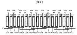
図7と図8を用いて、本発明の第3の実施形態による永久磁石式14極18スロットブラシレスモータの構成を説明する。
図9と図10を用いて、本発明の第4の実施形態による永久磁石式14極18スロットブラシレスモータの構成を説明する。
Claims (4)
- 集中巻固定子と永久磁石式回転子を備えるブラシレスモータにおいて、
直列に巻回されるティースの数が3以上であり、
口出し線に接続されるティースの巻線に隣接して接続される巻線がある場合はそれらの合計巻回数を端巻回数とし、
あるいは、前記口出し線に接続されるティースの巻線に隣接して接続される巻線がない場合は前記口出し線に接続されるティースの巻線の巻回数を端巻回数とし、
前記口出し線に接続されるティースの巻線あるいは隣接して接続される巻線から隣接より遠くのティースの巻線と渡り線で接続されて、別の口出し線に接続されるティースの巻線あるいは隣接して接続される巻線ではないティースの巻線の巻回数を中巻回数とし、
あるいは、前記の渡り線で接続された隣接より遠くのティースの巻線に隣接して接続される巻線がある場合はそれらの合計巻回数を中巻回数とし、あるいは、前記の渡り線で接続された隣接より遠くのティースの巻線が存在しない場合は中巻回数を0とするとき、
前記端巻回数が半整数であり、前記中巻回数が整数であるように、巻回された固定子巻線で構成されるブラシレスモータ。 - 請求項1に記載のブラシレスモータであって、
前記口出し線に接続されるティースの巻線の巻回数を半整数とし、
前記別の口出し線に接続されるティースの巻線の巻回数を半整数とし、
前記口出し線に接続されるティースの巻線とは渡り線で隣接より遠くに接続されており、
前記別の口出し線に接続されるティースの巻線とも渡り線で隣接より遠くに接続されているティースの巻線の巻回数を整数とするように巻回された固定子巻線で構成される、14極18スロットまたは22極18スロットまたはその倍数の極スロット組合せの、集中巻固定子と永久磁石式回転子を備えるブラシレスモータ。 - 請求項1に記載のブラシレスモータであって、
前記口出し線に接続されるティースの巻線とそれに隣接して接続される巻線の合計巻回数を半整数とし、
前記口出し線に接続されるティースの巻線に隣接して接続される巻線から渡り線で隣接より遠くに接続され、
前記別の口出し線に接続されるティースの巻線の巻回数を半整数とするように巻回された固定子巻線で構成される、14極18スロットまたは22極18スロットまたはその倍数の極スロット組合せの、集中巻固定子と永久磁石式回転子を備えるブラシレスモータ。 - 請求項1ないし3に記載のいずれかのブラシレスモータであって、
電動パワーステアリング又は電動ブレーキの自動車補機に用いられるブラシレスモータ。
Priority Applications (5)
| Application Number | Priority Date | Filing Date | Title |
|---|---|---|---|
| JP2016090040A JP6650336B2 (ja) | 2016-04-28 | 2016-04-28 | 回転電機 |
| EP17789149.6A EP3451505A4 (en) | 2016-04-28 | 2017-03-27 | ELECTRIC LATHE |
| CN201780025692.7A CN109075638B (zh) | 2016-04-28 | 2017-03-27 | 旋转电机 |
| PCT/JP2017/012217 WO2017187860A1 (ja) | 2016-04-28 | 2017-03-27 | 回転電機 |
| US16/094,004 US20190131840A1 (en) | 2016-04-28 | 2017-03-27 | Rotary Electric Machine |
Applications Claiming Priority (1)
| Application Number | Priority Date | Filing Date | Title |
|---|---|---|---|
| JP2016090040A JP6650336B2 (ja) | 2016-04-28 | 2016-04-28 | 回転電機 |
Publications (3)
| Publication Number | Publication Date |
|---|---|
| JP2017200335A JP2017200335A (ja) | 2017-11-02 |
| JP2017200335A5 JP2017200335A5 (ja) | 2019-02-21 |
| JP6650336B2 true JP6650336B2 (ja) | 2020-02-19 |
Family
ID=60160340
Family Applications (1)
| Application Number | Title | Priority Date | Filing Date |
|---|---|---|---|
| JP2016090040A Expired - Fee Related JP6650336B2 (ja) | 2016-04-28 | 2016-04-28 | 回転電機 |
Country Status (5)
| Country | Link |
|---|---|
| US (1) | US20190131840A1 (ja) |
| EP (1) | EP3451505A4 (ja) |
| JP (1) | JP6650336B2 (ja) |
| CN (1) | CN109075638B (ja) |
| WO (1) | WO2017187860A1 (ja) |
Families Citing this family (3)
| Publication number | Priority date | Publication date | Assignee | Title |
|---|---|---|---|---|
| JP6912508B2 (ja) * | 2019-03-19 | 2021-08-04 | ファナック株式会社 | 固定子および電動機 |
| DE112019006919B4 (de) * | 2019-03-27 | 2022-06-30 | Mitsubishi Electric Corporation | Stator und Elektromotor |
| JP7019105B1 (ja) * | 2020-12-23 | 2022-02-14 | 三菱電機株式会社 | 永久磁石式回転電機 |
Family Cites Families (12)
| Publication number | Priority date | Publication date | Assignee | Title |
|---|---|---|---|---|
| US6472790B2 (en) * | 2000-02-24 | 2002-10-29 | Briggs & Stratton Corporation | Stator for an electric motor/generator with a half-integer winding |
| JP2009213257A (ja) * | 2008-03-04 | 2009-09-17 | Hitachi Ltd | 回転電機 |
| US8072112B2 (en) * | 2008-06-16 | 2011-12-06 | Asmo Co., Ltd. | Motor, stator, and method for manufacturing stator |
| WO2010103634A1 (ja) * | 2009-03-11 | 2010-09-16 | 株式会社 日立製作所 | 車両用交流発電機 |
| JP5510703B2 (ja) * | 2009-08-21 | 2014-06-04 | 株式会社デンソー | 回転電機及びその制御システム |
| CN102468731B (zh) * | 2010-11-15 | 2014-06-11 | 京能新能源科技(上海)有限公司 | 一种永磁同步电机定子 |
| CN102142723A (zh) * | 2010-11-22 | 2011-08-03 | 常州市裕成富通电机有限公司 | 电动车用电机定子及其绕组的半匝绕制方法 |
| DE102011078157A1 (de) * | 2011-06-28 | 2013-01-03 | Robert Bosch Gmbh | Elektrische Maschine |
| JP2013118750A (ja) * | 2011-12-02 | 2013-06-13 | Hitachi Ltd | アキシャルギャップ型回転電機及びその製造方法 |
| WO2013136646A1 (ja) * | 2012-03-13 | 2013-09-19 | パナソニック株式会社 | モータおよびそのステータの製造方法 |
| JP2016052224A (ja) * | 2014-09-02 | 2016-04-11 | アイシン精機株式会社 | ステータ、そのステータを適用した回転電機及びステータの結線方法 |
| TWI551008B (zh) * | 2015-01-27 | 2016-09-21 | 建準電機工業股份有限公司 | 馬達繞組 |
-
2016
- 2016-04-28 JP JP2016090040A patent/JP6650336B2/ja not_active Expired - Fee Related
-
2017
- 2017-03-27 EP EP17789149.6A patent/EP3451505A4/en not_active Withdrawn
- 2017-03-27 US US16/094,004 patent/US20190131840A1/en not_active Abandoned
- 2017-03-27 WO PCT/JP2017/012217 patent/WO2017187860A1/ja active Application Filing
- 2017-03-27 CN CN201780025692.7A patent/CN109075638B/zh not_active Expired - Fee Related
Also Published As
| Publication number | Publication date |
|---|---|
| CN109075638B (zh) | 2020-11-10 |
| JP2017200335A (ja) | 2017-11-02 |
| WO2017187860A1 (ja) | 2017-11-02 |
| EP3451505A1 (en) | 2019-03-06 |
| EP3451505A4 (en) | 2019-12-25 |
| CN109075638A (zh) | 2018-12-21 |
| US20190131840A1 (en) | 2019-05-02 |
Similar Documents
| Publication | Publication Date | Title |
|---|---|---|
| US10862355B2 (en) | Armature with a core having teeth of different circumferential widths and electric motor including the armature and a rotor | |
| JP5040303B2 (ja) | 回転電機 | |
| JP6307324B2 (ja) | ブラシレスモータおよびこれを用いた電動パワーステアリング装置 | |
| US9627935B2 (en) | Multi-gap rotating electric machine having phase coils formed of substantially U-shaped electric conductor segments | |
| JPWO2017090514A1 (ja) | 回転電機および回転電機システム | |
| JP2006311733A (ja) | 回転電機の巻線構造 | |
| JP6650336B2 (ja) | 回転電機 | |
| JP4654819B2 (ja) | モータ | |
| US20190013710A1 (en) | Rotary Electric Machine | |
| JP5457869B2 (ja) | 回転電機の固定子及び回転電機 | |
| JP6337132B2 (ja) | 回転電機の固定子、及びこれを備えた回転電機 | |
| JP2020089039A (ja) | 回転電機および自動車用電動補機システム | |
| JP2014093914A (ja) | ブラシレスモータ | |
| JP5965207B2 (ja) | モータのステータ | |
| US20210075273A1 (en) | Rotating electric machine and electric power steering device having rotating electric machine | |
| JP6064859B2 (ja) | 多相回転機 | |
| JP2010124577A (ja) | モータ | |
| CN212572208U (zh) | 三相定子绕组、电机定子总成及电机 | |
| JP2019047630A (ja) | 回転電機 | |
| JP2007267523A (ja) | ステータコイルの結線構造 | |
| JP6302698B2 (ja) | 回転電機ユニット | |
| JP2020028166A (ja) | 固定子、回転電機、自動車用電動補機システム | |
| WO2024057906A1 (ja) | 固定子 | |
| CN108233564B (zh) | 驱动电机的定子 | |
| JP6727295B2 (ja) | 永久磁石型モータ |
Legal Events
| Date | Code | Title | Description |
|---|---|---|---|
| A521 | Request for written amendment filed |
Free format text: JAPANESE INTERMEDIATE CODE: A523 Effective date: 20160509 |
|
| RD04 | Notification of resignation of power of attorney |
Free format text: JAPANESE INTERMEDIATE CODE: A7424 Effective date: 20170120 |
|
| RD04 | Notification of resignation of power of attorney |
Free format text: JAPANESE INTERMEDIATE CODE: A7424 Effective date: 20170126 |
|
| A521 | Request for written amendment filed |
Free format text: JAPANESE INTERMEDIATE CODE: A523 Effective date: 20190110 |
|
| A621 | Written request for application examination |
Free format text: JAPANESE INTERMEDIATE CODE: A621 Effective date: 20190110 |
|
| A521 | Request for written amendment filed |
Free format text: JAPANESE INTERMEDIATE CODE: A523 Effective date: 20190111 |
|
| TRDD | Decision of grant or rejection written | ||
| A01 | Written decision to grant a patent or to grant a registration (utility model) |
Free format text: JAPANESE INTERMEDIATE CODE: A01 Effective date: 20191224 |
|
| A61 | First payment of annual fees (during grant procedure) |
Free format text: JAPANESE INTERMEDIATE CODE: A61 Effective date: 20200120 |
|
| R150 | Certificate of patent or registration of utility model |
Ref document number: 6650336 Country of ref document: JP Free format text: JAPANESE INTERMEDIATE CODE: R150 |
|
| LAPS | Cancellation because of no payment of annual fees |