JP6630708B2 - Gaming machine - Google Patents
Gaming machine Download PDFInfo
- Publication number
- JP6630708B2 JP6630708B2 JP2017169923A JP2017169923A JP6630708B2 JP 6630708 B2 JP6630708 B2 JP 6630708B2 JP 2017169923 A JP2017169923 A JP 2017169923A JP 2017169923 A JP2017169923 A JP 2017169923A JP 6630708 B2 JP6630708 B2 JP 6630708B2
- Authority
- JP
- Japan
- Prior art keywords
- effect
- display
- special
- game
- executed
- Prior art date
- Legal status (The legal status is an assumption and is not a legal conclusion. Google has not performed a legal analysis and makes no representation as to the accuracy of the status listed.)
- Active
Links
Images


Landscapes
- Display Devices Of Pinball Game Machines (AREA)
Description
本発明は、可変表示を実行可能な遊技機に関する。 The present invention relates to a gaming machine capable of performing variable display.
従来の遊技機には、可変表示に対応する特定表示に作用する作用演出を実行可能であり、該作用演出の作用によって特定表示の表示態様を変化可能なものがある(例えば、特許文献1参照)。 2. Description of the Related Art Conventional gaming machines are capable of executing an action effect acting on a specific display corresponding to a variable display, and changing the display mode of the specific display by the effect of the effect effect (for example, see Patent Document 1). ).
しかしながら、特許文献1にあっては、作用演出の演出効果が不充分であるため、遊技興趣を向上できないという問題がある。
However, in
本発明は、このような問題点に着目してなされたもので、遊技興趣を向上できる遊技機を提供することを目的とする。 The present invention has been made in view of such a problem, and an object of the present invention is to provide a gaming machine capable of improving gaming interest.
前記課題を解決するために、本発明の手段Aに記載の遊技機は、
可変表示を実行可能な遊技機であって、
演出表示手段と、
可変表示に対応する特定表示を前記演出表示手段に表示可能な特定表示手段と、
演出を制御する演出制御手段と、を備え、
前記特定表示手段は、前記特定表示を第1表示態様と該第1表示態様とは異なる第2表示態様とで表示可能であり、
前記演出制御手段は、
前記特定表示の表示態様が前記第1表示態様から前記第2表示態様に変化する際に、前記特定表示に作用する作用演出と、
前記演出表示手段の少なくとも一部の視認性を変化させる視認性変化演出と、
前記作用演出の実行を示唆する第1示唆演出と、該第1示唆演出とは異なる第2示唆演出と、を実行可能であり、
前記第2示唆演出を実行したときは、前記第1示唆演出を実行したときよりも高い割合で前記作用演出を実行可能であり、
前記作用演出を開始した後であって、特定表示の表示態様が前記第1表示態様から前記第2表示態様に変化する前に、前記視認性変化演出を前記作用演出と重複して実行可能であり、
前記作用演出は、第1作用演出と、該第1作用演出の後に実行される第2作用演出と、を含み、
前記視認性変化演出を前記第1作用演出と重複して実行する期間よりも、前記視認性変化演出を前記第2作用演出と重複して実行する期間の方が長い、
ことを特徴とする。
前記課題を解決するために、本発明の手段1に記載の遊技機は、
可変表示を実行可能な遊技機(例えば、パチンコ遊技機1)であって、
演出表示手段(例えば、画像表示装置5)と、
可変表示に対応する特定表示を前記演出表示手段に表示可能な特定表示手段(例えば、アクティブ表示エリア81SG5Fや、第1保留記憶表示エリア81SG5Dや第2保留記憶表示エリア81SG5Uに表示されている保留表示)と、
演出を制御する演出制御手段(例えば、演出制御用CPU120)と、を備え、
前記特定表示手段は、前記特定表示を第1表示態様(例えば、白色)と該第1表示態様とは異なる第2表示態様(例えば、青色や赤色)とで表示可能であり、
前記演出制御手段は、
前記特定表示の表示態様が前記第1表示態様から前記第2表示態様に変化する際に、前記特定表示に作用する作用演出(例えば、図8−27(L)に示すように、槍81SG603がアクティブ表示エリア81SG5Fに刺さる作用演出)と、
前記演出表示手段の少なくとも一部の視認性を変化させる視認性変化演出(例えば、図8−27(M)や図8−27(N)に示すように、画像表示装置5に表示されている画像全体を左右に振動させる振動表示演出)と、
前記作用演出の実行を示唆する第1示唆演出と、該第1示唆演出とは異なる第2示唆演出と、を実行可能であり、
前記第2示唆演出を実行したときは、前記第1示唆演出を実行したときよりも高い割合で前記作用演出を実行可能であり、
前記作用演出を実行する際に前記視認性変化演出を実行可能である(例えば、図8−27(L)〜図8−27(N)に示すように、アクティブ表示エリア81SG5Fに槍81SG603が刺さった後に画像表示装置5に表示されている画像全体が左右に振動する部分)ことを特徴としている。
この特徴によれば、演出効果を向上させることができ、遊技興趣を向上できる。
In order to solve the above-mentioned problems, a gaming machine according to the means A of the present invention is provided with:
A gaming machine capable of performing variable display,
Effect display means,
Specific display means capable of displaying a specific display corresponding to the variable display on the effect display means,
Effect control means for controlling the effect,
The specific display means is capable of displaying the specific display in a first display mode and a second display mode different from the first display mode,
The effect control means,
When the display mode of the specific display changes from the first display mode to the second display mode, an action effect acting on the specific display;
A visibility change effect of changing the visibility of at least a part of the effect display means,
A first suggestion effect suggesting execution of the action effect, and a second suggestion effect different from the first suggestion effect,
When the second suggestion effect is executed, the action effect can be executed at a higher rate than when the first suggestion effect is executed,
After the action effect is started, and before the display mode of the specific display changes from the first display mode to the second display mode, the visibility change effect can be executed in an overlapping manner with the action effect. Yes,
The action effect includes a first action effect, and a second action effect performed after the first action effect,
A period in which the visibility change effect is performed overlapping with the second operation effect is longer than a period in which the visibility change effect is performed in overlap with the first operation effect,
It is characterized by the following.
In order to solve the above-mentioned problems, a gaming machine according to a first aspect of the present invention provides:
A gaming machine (eg, a pachinko gaming machine 1) capable of performing variable display,
Effect display means (for example, image display device 5);
Specific display means capable of displaying a specific display corresponding to the variable display on the effect display means (for example, the active display area 81SG5F, the hold display displayed in the first hold storage display area 81SG5D, or the second hold storage display area 81SG5U) )When,
Effect control means (for example, effect control CPU 120) for controlling the effect,
The specific display means can display the specific display in a first display mode (for example, white) and a second display mode (for example, blue or red) different from the first display mode,
The effect control means,
When the display mode of the specific display changes from the first display mode to the second display mode, an action effect acting on the specific display (for example, as shown in FIG. 8-27 (L), the spear 81SG603 Action display effect of stabbing in the active display area 81SG5F),
A visibility change effect that changes the visibility of at least a part of the effect display means (for example, as shown in FIG. 8-27 (M) or FIG. 8-27 (N), is displayed on the image display device 5). Vibration display effect that vibrates the entire image left and right),
A first suggestion effect suggesting execution of the action effect, and a second suggestion effect different from the first suggestion effect;
When the second suggestion effect is executed, the action effect can be executed at a higher rate than when the first suggestion effect is executed,
When performing the action effect, the visibility change effect can be executed (for example, as shown in FIGS. 8-27 (L) to 8-27 (N), a spear 81SG603 is stuck in the active display area 81SG5F). (A portion where the entire image displayed on the
According to this feature, it is possible to improve the effect of the effect, and it is possible to improve the entertainment of the game.
本発明の手段2の遊技機は、手段1に記載の遊技機であって、
前記演出制御手段は、
前記作用演出の実行を示唆する示唆演出を第1態様(例えば、図8−27(J)及び図8−27(K)に示すように、槍81SG603がアクティブ表示エリア81SG5Fに向けて飛来するも槍81SG603がアクティブ表示エリア81SG5Fに刺さらない演出)と該第1態様とは異なる第2態様(例えば、図8−27(J)、図8−27(L)に示すように、槍81SG603がアクティブ表示エリア81SG5Fに向けて飛来し、槍81SG603がアクティブ表示エリア81SG5Fに刺さる演出)とで実行可能であり、
前記示唆演出を前記第2態様にて実行した場合は、前記示唆演出を前記第1態様にて実行した場合よりも高い割合で前記作用演出と前記視認性変化演出を実行する(例えば、図8−27及び図8−28に示すように、槍81SG603がアクティブ表示エリア81SG5Fに刺さらなかった場合は作用演出と振動表示演出が実行されない一方で、槍81SG603がアクティブ表示エリア81SG5Fに刺さった場合は作用演出と振動表示演出が実行される部分)
ことを特徴としている。
この特徴によれば、示唆演出の演出態様に遊技者を注目させることができ、遊技興趣を向上できる。
尚、示唆演出を第2態様にて実行した場合に示唆演出を第1態様にて実行した場合よりも高い割合で作用演出と視認性変化演出を実行することには、示唆演出を第2態様にて実行した場合には100%の割合で作用演出と視認性変化演出とを実行し、示唆演出を第1態様にて実行した場合には0%の割合で作用演出と視認性変化演出とを実行する、つまり、作用演出と視認性変化演出とを実行しない形態を含んでいる。
The gaming machine according to the second aspect of the present invention is the gaming machine according to the first aspect,
The effect control means,
In the first embodiment (for example, as shown in FIGS. 8-27 (J) and 8-27 (K)), the spear 81SG603 flies toward the active display area 81SG5F. An effect in which the spear 81SG603 is not stuck in the active display area 81SG5F) and a second mode different from the first mode (for example, as shown in FIGS. 8-27 (J) and 8-27 (L)), the spear 81SG603 is active. (The effect of flying toward the display area 81SG5F and causing the spear 81SG603 to stab in the active display area 81SG5F).
When the suggestion effect is executed in the second aspect, the action effect and the visibility change effect are executed at a higher rate than when the suggestion effect is executed in the first aspect (for example, FIG. 8). As shown in −27 and FIGS. 8 to 28, when the spear 81SG603 does not pierce the active display area 81SG5F, the action effect and the vibration display effect are not executed. The part where the effect and the vibration display effect are executed)
It is characterized by:
According to this feature, it is possible to make the player pay attention to the production mode of the suggestion production, and it is possible to improve the entertainment of the game.
It should be noted that performing the action effect and the visibility change effect at a higher rate when the suggestion effect is performed in the second mode than when the suggestion effect is performed in the first mode includes the suggestion effect in the second mode. In the case where the effect effect and the visibility change effect are executed at a rate of 100%, the effect effect and the visibility change effect are executed at a rate of 0% when the suggestion effect is executed in the first mode. , Ie, a form in which the action effect and the visibility change effect are not executed.
本発明の手段3の遊技機は、手段1または手段2に記載の遊技機であって、
前記演出制御手段は、
前記特定表示を対象とする演出として、前記作用演出及び前記視認性変化演出とは異なる特殊演出(例えば、変形例2に示すように、アクティブ表示エリア81SG5Fの大きさや形状を変化させる演出)を実行可能であり、
前記作用演出と前記視認性変化演出と前記特殊演出とを1の可変表示中に実行可能である(例えば、変形例2に示すように、作用演出及び振動表示演出とともに、アクティブ表示エリア81SG5Fの大きさや形状を変化させる演出を1の変動表示中に実行可能とする部分)
ことを特徴としている。
この特徴によれば、1の可変表示中に実行される演出数に遊技者を注目させることができ、遊技興趣を向上できる。
The gaming machine according to the third aspect of the present invention is the gaming machine according to the first or second aspect,
The effect control means,
As the effect directed to the specific display, a special effect different from the effect effect and the visibility change effect (for example, an effect of changing the size and shape of the active display area 81SG5F as shown in Modification 2) is executed. Is possible,
The action effect, the visibility change effect, and the special effect can be executed during the variable display of 1. (For example, as shown in
It is characterized by:
According to this feature, it is possible to make the player pay attention to the number of effects performed during one variable display, and it is possible to improve the interest in the game.
本発明の手段4の遊技機は、手段3に記載の遊技機であって、
前記演出制御手段は、前記特殊演出の実行中に前記作用演出を実行しない(例えば、変形例2に示すように、作用演出及び振動表示演出とともに、アクティブ表示エリア81SG5Fを対象とする演出(例えば、アクティブ表示エリア81SG5Fの大きさや形状を変化させる演出等)を1の変動表示中に実行可能とする場合は、アクティブ表示エリア81SG5Fを対象とする演出の実行中には、作用演出が実行されないように各演出実行可能期間をずらす部分)
ことを特徴としている。
この特徴によれば、特殊演出と作用演出の演出期間が重複することを防ぐことができるので、特殊演出に遊技者の注目を集めることができ、遊技興趣を向上できる。
The gaming machine according to the fourth aspect of the present invention is the gaming machine according to the third aspect,
The effect control means does not execute the action effect during the execution of the special effect (for example, as shown in
It is characterized by:
According to this feature, it is possible to prevent the effect periods of the special effect and the action effect from overlapping, so that the special effect can attract the player's attention and the entertainment interest of the game can be improved.
本発明の手段5の遊技機は、手段1〜手段4のいずれかに記載の遊技機であって、
前記特定表示は、実行中の可変表示に対応する表示(例えば、アクティブ表示エリア81SG5F)であり、
前記特定表示手段は、可変表示の実行中に前記特定表示を第1特定態様にて表示し(例えば、アクティブ表示エリア81SG5Fの発光を開始する部分)、可変表示を終了する際に前記特定表示を前記第1特定態様とは異なる第2特定態様にて表示する(例えば、アクティブ表示エリア81SG5Fの発光を終了する部分)
ことを特徴としている。
この特徴によれば、特定表示が第1特定態様にて表示されることによって可変表示の実行中であることを遊技者に明確に認識させることができるので、遊技興趣を向上できる。
The gaming machine of the
The specific display is a display corresponding to the variable display being executed (for example, the active display area 81SG5F).
The specific display means displays the specific display in the first specific mode during execution of the variable display (for example, a portion where light emission of the active display area 81SG5F starts), and displays the specific display when ending the variable display. The display is performed in a second specific mode different from the first specific mode (for example, a part where light emission of the active display area 81SG5F ends).
It is characterized by:
According to this feature, since the specific display is displayed in the first specific mode, the player can clearly recognize that the variable display is being executed, so that the interest in the game can be improved.
本発明の手段6の遊技機は、手段1〜手段5のいずれかに記載の遊技機であって、
可変表示に関する情報について保留記憶として記憶可能な保留記憶手段(例えば、CPU103が図8−9に示す始動入賞判定処理を実行する部分)と、
前記保留記憶に対応する保留表示を表示可能な特別表示手段(例えば、演出制御用CPU120がアクティブ表示・保留表示更新処理を実行する部分)と、
を備え、
前記演出制御手段は、
新たな可変表示が開始される際に、前記特別表示手段に表示されている前記保留表示が前記特定表示として前記特定表示手段に移行するエフェクト表示を表示するエフェクト表示演出(例えば、変形例3に示す移行演出)を実行可能であり、
前記特定表示が前記第2特定態様から前記第1特定態様に変化する際に、前記エフェクト表示演出を実行可能である(例えば、変形例3に示すように、アクティブ表示エリア81SG5Fが発光を開始する際に該移行演出を実行する部分)
ことを特徴としている。
この特徴によれば、可変表示を開始する際の演出により遊技者を注目させることができ、遊技興趣を向上できる。
The gaming machine of the
Holding storage means (for example, a part in which the
Special display means capable of displaying a hold display corresponding to the hold storage (for example, a part where the
With
The effect control means,
When a new variable display is started, an effect display effect in which the suspended display displayed on the special display means displays an effect display that shifts to the specific display means as the specific display (for example, in the third modification, Transition effect shown) is executable,
When the specific display changes from the second specific mode to the first specific mode, the effect display effect can be executed (for example, as shown in
It is characterized by:
According to this feature, it is possible to draw the player's attention by the effect at the time of starting the variable display, and it is possible to improve the interest in the game.
本発明の手段7の遊技機は、手段1〜手段6のいずれかに記載の遊技機であって、
可変表示を開始するときに遊技者にとって有利な有利状態(例えば、大当り遊技状態)に制御されるか否かを決定する決定手段(例えば、CPU103が特別図柄通常処理を実行する部分)と、
可変表示に関する情報について保留記憶として記憶可能な保留記憶手段(例えば、CPU103が図8−9に示す始動入賞判定処理を実行する部分)と、
前記保留記憶に対応する可変表示について、前記決定手段の決定前に前記有利状態に制御されるか否かを判定する判定手段(例えば、CPU103が図8−10に示す入賞時乱数値判定処理を実行する部分)と、
前記保留記憶に対応する保留表示を表示可能な特別表示手段(例えば、演出制御用CPU120がアクティブ表示・保留表示更新処理を実行する部分)と、
可変表示の実行中に特定表示を前記保留表示とは異なる領域に表示可能な特定表示手段(例えば、演出制御用CPU120がアクティブ表示・保留表示更新処理を実行する部分)と、
を備え、
前記特定表示手段は、
前記判定手段の判定に基づいて、前記特定表示を特別表示態様(例えば、大きさの異なるのこぎり波)にて表示する特別演出(例えば、波形予告演出)と、
前記決定手段の決定に基づいて、前記特定表示を前記特別表示態様とは異なる特定表示態様(例えば、青色や赤色)にて表示する特定演出(例えば、アクティブ表示エリア変化演出)を実行可能であり、
特定表示は、前記保留表示よりも視認性が高い(例えば、アクティブ表示エリア81SG5Fは、画像表示装置5の下部において、左右方向の中央部に表示されているとともに、各保留表示よりも表示面積が大きいため、各保留表示よりも遊技者からの視認性が高くなっている部分)
ことを特徴としている。
この特徴によれば、保留表示よりも視認性が高い特定表示を特別表示態様や特殊表示態様にて表示することで特別演出や特定演出を実行するので、特定表示の態様に遊技者の注目を集めることができ、遊技興趣を向上できる。
The gaming machine of the
Determining means (for example, a portion in which the
Holding storage means (for example, a part in which the
Judgment means for determining whether or not the variable display corresponding to the hold storage is controlled to the advantageous state before the determination by the determination means (for example, the
Special display means capable of displaying a hold display corresponding to the hold storage (for example, a part where the
Specific display means capable of displaying the specific display in an area different from the suspended display during execution of the variable display (for example, a portion where the
With
The specific display means,
A special effect (for example, a waveform notice effect) in which the specific display is displayed in a special display mode (for example, sawtooth waves having different sizes) based on the determination by the determination unit;
It is possible to execute a specific effect (for example, an active display area change effect) in which the specific display is displayed in a specific display mode (for example, blue or red) different from the special display mode, based on the determination by the determining unit. ,
The specific display has higher visibility than the reserved display (for example, the active display area 81SG5F is displayed at the center of the lower part of the
It is characterized by:
According to this feature, the special effect or the special effect is executed by displaying the specific display having higher visibility than the hold display in the special display mode or the special display mode, so that the player pays attention to the specific display mode. You can collect and improve the entertainment interest.
本発明の手段8の遊技機は、手段1〜手段7のいずれかに記載の遊技機であって、
前記作用演出は、前記特定表示に対して作用表示(例えば、変形例1に示すカラーボール81SG931)を作用させる演出であり、
前記演出制御手段は、
前記作用演出を、前記作用表示の表示を開始し、所定期間経過後に前記特定表示の表示態様を変化させる第1パターン(例えば、変形例1として図8−31(C)に示す成功パターン)と、前記作用表示の表示を開始し、所定期間経過後に前記特定表示の表示態様を変化させない第2パターン(例えば、変形例1として図8−31(D)に示す失敗パターン)と、で実行可能であり、
前記作用表示の表示を開始した後、前記第1パターンと前記第2パターンとの所定期間における共通のタイミングにおいて、対象とする前記特定表示に対する前記作用表示の速度を減速させて表示可能であり(例えば、変形例1として図8−31(B)に示す減速制御を実行する部分)、
前記作用表示の速度を減速させて表示する場合は、対象となる前記特定表示及び前記作用表示と、対象となる前記特定表示及び前記作用表示以外の表示とのうち、少なくともいずれか一方の表示態様を前記作用表示の速度を減速させて表示する前の表示態様から変化させて表示可能である(例えば、変形例1として図8−31(B)に示すように、作用表示の速度を減速させて表示する場合は、保留表示やアクティブ表示エリア81SG5F、カラーボール81SG931以外の表示態様を、薄暗く表示する部分)
ことを特徴としている。
この特徴によれば、作用表示に変化を与えることによって遊技の興趣を向上させることができる。また、対象となる特定表示が変化するか否かを効果的に煽ることができる。
The gaming machine of the
The action effect is an effect in which an action display (for example, the color ball 81SG931 shown in Modification Example 1) is applied to the specific display,
The effect control means,
A first pattern (for example, a success pattern shown in FIG. 8-31 (C) as a first modification) for changing the display mode of the specific display after the display of the operation display is started and a predetermined period has elapsed after a predetermined period has elapsed. , The display of the action display is started, and can be executed by a second pattern (for example, a failure pattern shown in FIG. 8-31 (D) as a first modification) in which the display mode of the specific display is not changed after a predetermined period has elapsed. And
After the display of the operation display is started, at a common timing in the predetermined period of the first pattern and the second pattern, the speed of the operation display with respect to the specific display to be displayed can be reduced and displayed ( For example, a portion that executes the deceleration control shown in FIG.
When the speed of the action display is reduced and displayed, at least one of the target specific display and the action display and at least one of the display other than the target specific display and the action display is displayed. Can be displayed by changing the display mode before the operation display is reduced and displayed (for example, as shown in FIG. 8-31 (B) as a first modification, the operation display speed is reduced. In the case of displaying the display mode, the display mode other than the hold display, the active display area 81SG5F, and the color ball 81SG931 is dimly displayed.
It is characterized by:
According to this feature, the interest in the game can be improved by changing the action display. Further, it is possible to effectively fan whether or not the target specific display changes.
本発明の手段9の遊技機は、手段8に記載の遊技機であって、
前記演出制御手段は、
前記作用表示の速度を第1期間(例えば、3秒間)と該第1期間とは異なる第2期間(例えば、5秒間)とに亘って減速させて表示可能であり、
前記作用演出を第1パターンにて実行する場合は、前記作用演出を前記第2パターンにて実行する場合よりも高い割合で前記作用表示の速度を前記第2期間に亘って減速させて表示する(例えば、変形例1として図8−33に示すように、作用演出を第1パターンにて実行する場合は、作用演出第2パターンにて実行する場合よりも高い割合で5秒間に亘ってカラーボール81SG931の速度の減速を実行する部分)
ことを特徴としている。
この特徴によれば、作用表示の速度を減速させる期間に遊技者を注目させることができるので、遊技興趣を向上できる。
The gaming machine of the
The effect control means,
The speed of the action display can be reduced and displayed over a first period (for example, 3 seconds) and a second period (for example, 5 seconds) different from the first period, and
When the action effect is executed in the first pattern, the action display speed is reduced and displayed at a higher rate than when the action effect is executed in the second pattern over the second period. (For example, as shown in FIGS. 8 to 33 as
It is characterized by:
According to this feature, the player can be noticed during the period in which the speed of the action display is reduced, so that the interest in the game can be improved.
尚、本発明は、本発明の請求項に記載された発明特定事項のみを有するものであって良いし、本発明の請求項に記載された発明特定事項とともに該発明特定事項以外の構成を有するものであっても良い。 It should be noted that the present invention may have only the matters specifying the invention described in the claims of the present invention, or may have configurations other than the matters specifying the invention together with the matters specifying the invention described in the claims of the present invention. It may be something.
(基本説明)
まず、パチンコ遊技機1の基本的な構成及び制御(一般的なパチンコ遊技機の構成及び制御でもある。)について説明する。
(Basic explanation)
First, the basic configuration and control of the pachinko gaming machine 1 (also the configuration and control of a general pachinko gaming machine) will be described.
(パチンコ遊技機1の構成等)
図1は、パチンコ遊技機1の正面図であり、主要部材の配置レイアウトを示す。パチンコ遊技機(遊技機)1は、大別して、遊技盤面を構成する遊技盤(ゲージ盤)2と、遊技盤2を支持固定する遊技機用枠(台枠)3とから構成されている。遊技盤2には、遊技領域が形成され、この遊技領域には、遊技媒体としての遊技球が、所定の打球発射装置から発射されて打ち込まれる。
(Structure of
FIG. 1 is a front view of the
遊技盤2の所定位置(図1に示す例では、遊技領域の右側方)には、複数種類の特別識別情報としての特別図柄(特図ともいう)の可変表示(特図ゲームともいう)を行う第1特別図柄表示装置4A及び第2特別図柄表示装置4Bが設けられている。これらは、それぞれ、7セグメントのLEDなどからなる。特別図柄は、「0」〜「9」を示す数字や「−」などの点灯パターンなどにより表される。特別図柄には、LEDを全て消灯したパターンが含まれてもよい。
At a predetermined position of the game board 2 (in the example shown in FIG. 1, on the right side of the game area), a variable display (also called a special figure game) of a special symbol (also called a special figure) as a plurality of types of special identification information is provided. A first special
なお、特別図柄の「可変表示」とは、例えば、複数種類の特別図柄を変動可能に表示することである(後述の他の図柄についても同じ)。変動としては、複数の図柄の更新表示、複数の図柄のスクロール表示、1以上の図柄の変形、1以上の図柄の拡大/縮小などがある。特別図柄や後述の普通図柄の変動では、複数種類の特別図柄又は普通図柄が更新表示される。後述の飾り図柄の変動では、複数種類の飾り図柄がスクロール表示又は更新表示されたり、1以上の飾り図柄が変形や拡大/縮小されたりする。なお、変動には、ある図柄を点滅表示する態様も含まれる。可変表示の最後には、表示結果として所定の特別図柄が停止表示(導出又は導出表示などともいう)される(後述の他の図柄の可変表示についても同じ)。なお、可変表示を変動表示、変動と表現する場合がある。 The “variable display” of a special symbol is, for example, to display a plurality of types of special symbols in a variable manner (the same applies to other symbols described later). The fluctuation includes update display of a plurality of symbols, scroll display of a plurality of symbols, deformation of one or more symbols, enlargement / reduction of one or more symbols, and the like. In the case of the change of the special symbol or the ordinary symbol described later, a plurality of types of special symbols or ordinary symbols are updated and displayed. In the variation of the decorative symbols described later, a plurality of types of decorative symbols are scrolled or updated, and one or more decorative symbols are deformed or enlarged / reduced. In addition, the fluctuation includes a mode in which a certain symbol is blinked. At the end of the variable display, a predetermined special symbol is stopped (also referred to as derived or derived display) as a display result (the same applies to the variable display of other symbols described later). Note that the variable display may be referred to as a variable display or a variable display.
なお、第1特別図柄表示装置4Aにおいて可変表示される特別図柄を「第1特図」ともいい、第2特別図柄表示装置4Bにおいて可変表示される特別図柄を「第2特図」ともいう。また、第1特図を用いた特図ゲームを「第1特図ゲーム」といい、第2特図を用いた特図ゲームを「第2特図ゲーム」ともいう。なお、特別図柄の可変表示を行う特別図柄表示装置は1種類であってもよい。
The special symbol variably displayed on the first special
遊技盤2における遊技領域の中央付近には画像表示装置5が設けられている。画像表示装置5は、例えばLCD(液晶表示装置)や有機EL(Electro Luminescence)等から構成され、各種の演出画像を表示する。画像表示装置5は、プロジェクタ及びスクリーンから構成されていてもよい。画像表示装置5には、各種の演出画像が表示される。
An
例えば、画像表示装置5の画面上では、第1特図ゲームや第2特図ゲームと同期して、特別図柄とは異なる複数種類の装飾識別情報としての飾り図柄(数字などを示す図柄など)の可変表示が行われる。ここでは、第1特図ゲーム又は第2特図ゲームに同期して、「左」、「中」、「右」の各飾り図柄表示エリア5L、5C、5Rにおいて飾り図柄が可変表示(例えば上下方向のスクロール表示や更新表示)される。なお、同期して実行される特図ゲーム及び飾り図柄の可変表示を総称して単に可変表示ともいう。
For example, on the screen of the
画像表示装置5の画面上には、実行が保留されている可変表示に対応する保留表示や、実行中の可変表示に対応するアクティブ表示を表示するための表示エリアが設けられていてもよい。保留表示及びアクティブ表示を総称して可変表示に対応する可変表示対応表示ともいう。
On the screen of the
保留されている可変表示の数は保留記憶数ともいう。第1特図ゲームに対応する保留記憶数を第1保留記憶数、第2特図ゲームに対応する保留記憶数を第2保留記憶数ともいう。また、第1保留記憶数と第2保留記憶数との合計を合計保留記憶数ともいう。 The number of variable displays suspended is also referred to as the suspended storage number. The number of reserved storages corresponding to the first special figure game is also referred to as a first reserved storage number, and the number of reserved storages corresponding to the second special figure game is also referred to as a second reserved storage number. In addition, the sum of the first reserved storage number and the second reserved storage number is also referred to as a total reserved storage number.
また、遊技盤2の所定位置には、複数のLEDを含んで構成された第1保留表示器25Aと第2保留表示器25Bとが設けられ、第1保留表示器25Aは、LEDの点灯個数によって、第1保留記憶数を表示し、第2保留表示器25Bは、LEDの点灯個数によって、第2保留記憶数を表示する。
At a predetermined position of the
画像表示装置5の下方には、入賞球装置6Aと、可変入賞球装置6Bとが設けられている。
Below the
入賞球装置6Aは、例えば所定の玉受部材によって常に遊技球が進入可能な一定の開放状態に保たれる第1始動入賞口を形成する。第1始動入賞口に遊技球が進入したときには、所定個(例えば3個)の賞球が払い出されるとともに、第1特図ゲームが開始され得る。
The winning
可変入賞球装置6B(普通電動役物)は、ソレノイド81(図2参照)によって閉鎖状態と開放状態とに変化する第2始動入賞口を形成する。可変入賞球装置6Bは、例えば、一対の可動翼片を有する電動チューリップ型役物を備え、ソレノイド81がオフ状態であるときに可動翼片が垂直位置となることにより、当該可動翼片の先端が入賞球装置6Aに近接し、第2始動入賞口に遊技球が進入しない閉鎖状態になる(第2始動入賞口が閉鎖状態になるともいう。)。その一方で、可変入賞球装置6Bは、ソレノイド81がオン状態であるときに可動翼片が傾動位置となることにより、第2始動入賞口に遊技球が進入できる開放状態になる(第2始動入賞口が開放状態になるともいう。)。第2始動入賞口に遊技球が進入したときには、所定個(例えば3個)の賞球が払い出されるとともに、第2特図ゲームが開始され得る。なお、可変入賞球装置6Bは、閉鎖状態と開放状態とに変化するものであればよく、電動チューリップ型役物を備えるものに限定されない。
The variable winning
遊技盤2の所定位置(図1に示す例では、遊技領域の左右下方4箇所)には、所定の玉受部材によって常に一定の開放状態に保たれる一般入賞口10が設けられる。この場合には、一般入賞口10のいずれかに進入したときには、所定個数(例えば10個)の遊技球が賞球として払い出される。
At a predetermined position of the game board 2 (in the example shown in FIG. 1, four lower right and left sides of the game area), a general winning
入賞球装置6Aと可変入賞球装置6Bの下方には、大入賞口を有する特別可変入賞球装置7が設けられている。特別可変入賞球装置7は、ソレノイド82(図2参照)によって開閉駆動される大入賞口扉を備え、その大入賞口扉によって開放状態と閉鎖状態とに変化する特定領域としての大入賞口を形成する。
Below the winning
一例として、特別可変入賞球装置7では、大入賞口扉用(特別電動役物用)のソレノイド82がオフ状態であるときに大入賞口扉が大入賞口を閉鎖状態として、遊技球が大入賞口に進入(通過)できなくなる。その一方で、特別可変入賞球装置7では、大入賞口扉用のソレノイド82がオン状態であるときに大入賞口扉が大入賞口を開放状態として、遊技球が大入賞口に進入しやすくなる。
As an example, in the special variable winning
大入賞口に遊技球が進入したときには、所定個数(例えば14個)の遊技球が賞球として払い出される。大入賞口に遊技球が進入したときには、例えば第1始動入賞口や第2始動入賞口及び一般入賞口10に遊技球が進入したときよりも多くの賞球が払い出される。
When game balls enter the special winning opening, a predetermined number (for example, 14) of game balls are paid out as prize balls. When the game ball enters the big winning opening, more prize balls are paid out than when the game ball enters the first starting winning opening, the second starting winning opening, and the general winning
一般入賞口10を含む各入賞口に遊技球が進入することを「入賞」ともいう。特に、始動口(第1始動入賞口、第2始動入賞口始動口)への入賞を始動入賞ともいう。
A game ball entering each winning port including the general winning
遊技盤2の所定位置(図1に示す例では、遊技領域の左側方)には、普通図柄表示器20が設けられている。一例として、普通図柄表示器20は、7セグメントのLEDなどからなり、特別図柄とは異なる複数種類の普通識別情報としての普通図柄の可変表示を行う。普通図柄は、「0」〜「9」を示す数字や「−」などの点灯パターンなどにより表される。普通図柄には、LEDを全て消灯したパターンが含まれてもよい。このような普通図柄の可変表示は、普図ゲームともいう。
At a predetermined position of the game board 2 (in the example shown in FIG. 1, on the left side of the game area), a
画像表示装置5の左方には、遊技球が通過可能な通過ゲート41が設けられている。遊技球が通過ゲート41を通過したことに基づき、普図ゲームが実行される。
On the left side of the
普通図柄表示器20の上方には、普図保留表示器25Cが設けられている。普図保留表示器25Cは、例えば4個のLEDを含んで構成され、実行が保留されている普図ゲームの数である普図保留記憶数をLEDの点灯個数により表示する。
Above the
遊技盤2の表面には、上記の構成以外にも、遊技球の流下方向や速度を変化させる風車及び多数の障害釘が設けられている。遊技領域の最下方には、いずれの入賞口にも進入しなかった遊技球が取り込まれるアウト口が設けられている。
On the surface of the
遊技機用枠3の左右上部位置には、効果音等を再生出力するためのスピーカ8L、8Rが設けられており、さらに遊技領域周辺部には、遊技効果用の遊技効果ランプ9が設けられている。遊技効果ランプ9は、LEDを含んで構成されている。
遊技盤2の所定位置(図1では図示略)には、演出に応じて動作する可動体32が設けられている。
At a predetermined position (not shown in FIG. 1) of the
遊技機用枠3の右下部位置には、遊技球を打球発射装置により遊技領域に向けて発射するために遊技者等によって操作される打球操作ハンドル(操作ノブ)30が設けられている。
At a lower right position of the
遊技領域の下方における遊技機用枠3の所定位置には、賞球として払い出された遊技球や所定の球貸機により貸し出された遊技球を、打球発射装置へと供給可能に保持(貯留)する打球供給皿(上皿)が設けられている。上皿の下方には、上皿満タン時に賞球が払い出される打球供給皿(下皿)が設けられている。
At a predetermined position of the
遊技領域の下方における遊技機用枠3の所定位置には、遊技者が把持して傾倒操作が可能なスティックコントローラ31Aが取り付けられている。スティックコントローラ31Aには、遊技者が押下操作可能なトリガボタンが設けられている。スティックコントローラ31Aに対する操作は、コントローラセンサユニット35A(図2参照)により検出される。
At a predetermined position of the
遊技領域の下方における遊技機用枠3の所定位置には、遊技者が押下操作などにより所定の指示操作を可能なプッシュボタン31Bが設けられている。プッシュボタン31Bに対する操作は、プッシュセンサ35B(図2参照)により検出される。
At a predetermined position of the
パチンコ遊技機1では、遊技者の動作(操作等)を検出する検出手段として、スティックコントローラ31Aやプッシュボタン31Bが設けられるが、これら以外の検出手段が設けられていてもよい。
In the
(遊技の進行の概略)
パチンコ遊技機1が備える打球操作ハンドル30への遊技者による回転操作により、遊技球が遊技領域に向けて発射される。遊技球が通過ゲート41を通過すると、普通図柄表示器20による普図ゲームが開始される。なお、前回の普図ゲームの実行中の期間等に遊技球が通過ゲート41を通過した場合(遊技球が通過ゲート41を通過したが当該通過に基づく普図ゲームを直ちに実行できない場合)には、当該通過に基づく普図ゲームは所定の上限数(例えば4)まで保留される。
(Outline of the progress of the game)
A game ball is fired toward a game area by a rotation operation by a player on a hit ball operation handle 30 provided in the
この普図ゲームでは、特定の普通図柄(普図当り図柄)が停止表示されれば、普通図柄の表示結果が「普図当り」となる。その一方、確定普通図柄として、普図当り図柄以外の普通図柄(普図ハズレ図柄)が停止表示されれば、普通図柄の表示結果が「普図ハズレ」となる。「普図当り」となると、可変入賞球装置6Bを所定期間開放状態とする開放制御が行われる(第2始動入賞口が開放状態になる)。
In this ordinary symbol game, if a specific ordinary symbol (a symbol per ordinary symbol) is stopped and displayed, the display result of the ordinary symbol will be "per ordinary symbol". On the other hand, if a normal symbol (regular symbol lost symbol) other than the symbol per regular symbol is stopped and displayed as the determined ordinary symbol, the display result of the ordinary symbol is “regular symbol lost”. When "per day" is reached, opening control is performed to open the variable winning
入賞球装置6Aに形成された第1始動入賞口に遊技球が進入すると、第1特別図柄表示装置4Aによる第1特図ゲームが開始される。
When a game ball enters the first starting winning opening formed in the winning
可変入賞球装置6Bに形成された第2始動入賞口に遊技球が進入すると、第2特別図柄表示装置4Bによる第2特図ゲームが開始される。
When the game ball enters the second starting winning opening formed in the variable winning
なお、特図ゲームの実行中の期間や、後述する大当り遊技状態や小当り遊技状態に制御されている期間に、遊技球が始動入賞口へ進入(入賞)した場合(始動入賞が発生したが当該始動入賞に基づく特図ゲームを直ちに実行できない場合)には、当該進入に基づく特図ゲームは所定の上限数(例えば4)までその実行が保留される。 Note that, when the game ball enters (wins) the starting winning opening during a period during which the special figure game is being executed, or a period in which the game is controlled to the big hitting game state or the small hitting game state described later (the start winning prize has occurred. When the special figure game based on the start winning prize cannot be immediately executed), the execution of the special figure game based on the entry is suspended up to a predetermined upper limit number (for example, 4).
特図ゲームにおいて、確定特別図柄として特定の特別図柄(大当り図柄、例えば「7」、後述の大当り種別に応じて実際の図柄は異なる。)が停止表示されれば、「大当り」となり、大当り図柄とは異なる所定の特別図柄(小当り図柄、例えば「2」)が停止表示されれば、「小当り」となる。また、大当り図柄や小当り図柄とは異なる特別図柄(ハズレ図柄、例えば「−」)が停止表示されれば「ハズレ」となる。 In the special figure game, if a specific special symbol (big hit symbol, for example, “7”, the actual symbol is different depending on the big hit type to be described later) is stopped and displayed as the fixed special symbol, it becomes “big hit” and the big hit symbol If a predetermined special symbol (small hit symbol, for example, “2”) different from the above is stopped and displayed, “small hit” is obtained. If a special symbol (losing symbol, for example, “−”) different from the big hit symbol or the small hit symbol is stopped and displayed, “losing” is displayed.
特図ゲームでの表示結果が「大当り」になった後には、遊技者にとって有利な有利状態として大当り遊技状態に制御される。特図ゲームでの表示結果が「小当り」になった後には、小当り遊技状態に制御される。 After the display result in the special figure game becomes “big hit”, the big hit gaming state is controlled as an advantageous state advantageous to the player. After the display result in the special figure game becomes “small hit”, the game is controlled to the small hit game state.
大当り遊技状態においては、遊技者は、遊技球を大入賞口に進入させることで、賞球を得ることができる。従って、大当り遊技状態は、遊技者にとって有利な状態である。大当り遊技状態におけるラウンド数が多い程、また、開放上限期間が長い程遊技者にとって有利となる。 In the big hit game state, the player can obtain a prize ball by causing the game ball to enter the big winning opening. Therefore, the big hit gaming state is an advantageous state for the player. The greater the number of rounds in the big hit game state and the longer the open upper limit period, the more advantageous to the player.
なお、「大当り」には、大当り種別が設定されている。例えば、大入賞口の開放態様(ラウンド数や開放上限期間)や、大当り遊技状態後の遊技状態(後述の、通常状態、時短状態、確変状態など)を複数種類用意し、これらに応じて大当り種別が設定されている。大当り種別として、多くの賞球を得ることができる大当り種別や、賞球の少ない又はほとんど賞球を得ることができない大当り種別が設けられていてもよい。 Note that the "big hit" is set with a big hit type. For example, a plurality of types of opening modes of the special winning opening (the number of rounds and the upper limit period of opening) and a game state after the big hit game state (a normal state, a time saving state, a probable change state, etc. to be described later) are prepared. Type is set. As the big hit type, a big hit type where many prize balls can be obtained or a big hit type where few or almost no prize balls can be obtained may be provided.
小当り遊技状態では、特別可変入賞球装置7により形成される大入賞口が所定の開放態様で開放状態となる。例えば、小当り遊技状態では、一部の大当り種別のときの大当り遊技状態と同様の開放態様(大入賞口の開放回数が上記ラウンド数と同じであり、かつ、大入賞口の閉鎖タイミングも同じ等)で大入賞口が開放状態となる。なお、大当り種別と同様に、「小当り」にも小当り種別を設けてもよい。
In the small hitting game state, the special winning opening formed by the special variable winning
大当り遊技状態が終了した後は、上記大当り種別に応じて、時短状態や確変状態に制御されることがある。 After the big hitting game state is ended, the state may be controlled to a time saving state or a probable change state according to the above big hit type.
時短状態では、平均的な特図変動時間(特図を変動させる期間)を通常状態よりも短縮させる制御(時短制御)が実行される。時短状態では、平均的な普図変動時間(普図を変動させる期間)を通常状態よりも短縮させたり、普図ゲームで「普図当り」となる確率を通常状態よりも向上させる等により、第2始動入賞口に遊技球が進入しやすくなる制御(高開放制御、高ベース制御)も実行される。時短状態は、特別図柄(特に第2特別図柄)の変動効率が向上する状態であるので、遊技者にとって有利な状態である。 In the time saving state, control (time saving control) for shortening the average special figure fluctuation time (the period during which the special figure is fluctuated) is performed as compared with the normal state. In the time-saving state, the average time for fluctuating the figure (the period for fluctuating the figure) is shortened compared to the normal state, and the probability of "hitting the figure" in the figure drawing game is improved compared to the normal state. Controls (high opening control, high base control) that allow the game balls to easily enter the second start winning opening are also executed. The time saving state is a state in which the fluctuation efficiency of the special symbol (particularly, the second special symbol) is improved, and is a state advantageous to the player.
確変状態(確率変動状態)では、時短制御に加えて、表示結果が「大当り」となる確率が通常状態よりも高くなる確変制御が実行される。確変状態は、特別図柄の変動効率が向上することに加えて「大当り」となりやすい状態であるので、遊技者にとってさらに有利な状態である。 In the probability variation state (probability variation state), in addition to the time saving control, the probability variation control in which the probability that the display result is “big hit” is higher than in the normal state is executed. The probable change state is a state that is more advantageous to the player because the change efficiency of the special symbol is improved and a “big hit” is likely to occur.
時短状態や確変状態は、所定回数の特図ゲームが実行されたことと、次回の大当り遊技状態が開始されたこと等といった、いずれか1つの終了条件が先に成立するまで継続する。所定回数の特図ゲームが実行されたことが終了条件となるものを、回数切り(回数切り時短、回数切り確変等)ともいう。 The time-saving state and the probable change state continue until one of the end conditions such as the execution of the predetermined number of special figure games and the start of the next big hit game state is satisfied first. Execution of a predetermined number of special figure games as an end condition is also referred to as count cut (time cut, time cut probability change, etc.).
通常状態とは、遊技者にとって有利な大当り遊技状態等の有利状態、時短状態、確変状態等の特別状態以外の遊技状態のことであり、普図ゲームにおける表示結果が「普図当り」となる確率及び特図ゲームにおける表示結果が「大当り」となる確率などのパチンコ遊技機1が、パチンコ遊技機1の初期設定状態(例えばシステムリセットが行われた場合のように、電源投入後に所定の復帰処理を実行しなかったとき)と同一に制御される状態である。
The normal state is a game state other than a special state such as an advantageous state such as a jackpot game state that is advantageous to the player, a time-saving state, a probable change state, or the like. The
確変制御が実行されている状態を高確状態、確変制御が実行されていない状態を低確状態ともいう。時短制御が実行されている状態を高ベース状態、時短制御が実行されていない状態を低ベース状態ともいう。これらを組み合わせて、時短状態は低確高ベース状態、確変状態は高確高ベース状態、通常状態は低確低ベース状態などともいわれる。高確状態かつ低ベース状態は高確低ベース状態ともいう。 The state in which the probable change control is being executed is also referred to as a high-probability state, and the state in which the probable change control is not being executed is referred to as a low-probability state. The state in which the time-saving control is executed is also called a high base state, and the state in which the time-saving control is not executed is called a low base state. By combining these, the time saving state is also called a low-probability high-base state, the probable change state is a high-precision high-base state, and the normal state is also a low-probability low-base state. The high-accuracy and low-base state is also referred to as a high-accuracy low-base state.
小当り遊技状態が終了した後は、遊技状態の変更が行われず、特図ゲームの表示結果が「小当り」となる以前の遊技状態に継続して制御される(但し、「小当り」発生時の特図ゲームが、上記回数切りにおける上記所定回数目の特図ゲームである場合には、当然遊技状態が変更される)。なお、特図ゲームの表示結果として「小当り」がなくてもよい。 After the small hitting game state ends, the game state is not changed, and the control is continued to the game state before the display result of the special figure game becomes “small hit” (however, “small hit” occurs. If the special figure game at that time is the special figure game of the predetermined number of times in the above number cut, the game state is naturally changed). Note that the display result of the special figure game does not have to have “small hit”.
なお、遊技状態は、大当り遊技状態中に遊技球が特定領域(例えば、大入賞口内の特定領域)を通過したことに基づいて、変化してもよい。例えば、遊技球が特定領域を通過したとき、その大当り遊技状態後に確変状態に制御してもよい。 Note that the gaming state may change based on the fact that a game ball has passed a specific area (for example, a specific area within a special winning opening) during the big hit gaming state. For example, when a game ball passes through a specific area, the state may be controlled to be a positively changed state after the big hit game state.
(演出の進行など)
パチンコ遊技機1では、遊技の進行に応じて種々の演出(遊技の進行状況を報知したり、遊技を盛り上げたりする演出)が実行される。当該演出について以下説明する。なお、当該演出は、画像表示装置5に各種の演出画像を表示することによって行われるが、当該表示に加えて又は代えて、スピーカ8L、8Rからの音声出力、及び/又は、遊技効果ランプ9の点等/消灯、可動体32の動作等により行われてもよい。
(Progress of production etc.)
In the
遊技の進行に応じて実行される演出として、画像表示装置5に設けられた「左」、「中」、「右」の飾り図柄表示エリア5L、5C、5Rでは、第1特図ゲーム又は第2特図ゲームが開始されることに対応して、飾り図柄の可変表示が開始される。第1特図ゲームや第2特図ゲームにおいて表示結果(確定特別図柄ともいう。)が停止表示されるタイミングでは、飾り図柄の可変表示の表示結果となる確定飾り図柄(3つの飾り図柄の組合せ)も停止表示(導出)される。
In the “left”, “middle”, and “right” decorative
飾り図柄の可変表示が開始されてから終了するまでの期間では、飾り図柄の可変表示の態様が所定のリーチ態様となる(リーチが成立する)ことがある。ここで、リーチ態様とは、画像表示装置5の画面上にて停止表示された飾り図柄が後述の大当り組合せの一部を構成しているときに未だ停止表示されていない飾り図柄については可変表示が継続している態様などのことである。
During the period from the start to the end of the variable display of the decorative symbols, the mode of the variable display of the decorative symbols may be a predetermined reach mode (reach is established). Here, the reach mode is a variable display for a decorative symbol that is not yet stopped and displayed when the decorative symbol stopped and displayed on the screen of the
また、飾り図柄の可変表示中に上記リーチ態様となったことに対応してリーチ演出が実行される。パチンコ遊技機1では、演出態様に応じて表示結果(特図ゲームの表示結果や飾り図柄の可変表示の表示結果)が「大当り」となる割合(大当り信頼度、大当り期待度とも呼ばれる。)が異なる複数種類のリーチ演出が実行される。リーチ演出には、例えば、ノーマルリーチと、ノーマルリーチよりも大当り信頼度の高いスーパーリーチと、がある。
In addition, a reach effect is executed in response to the reach mode during the variable display of the decorative symbol. In the
特図ゲームの表示結果が「大当り」となるときには、画像表示装置5の画面上において、飾り図柄の可変表示の表示結果として、予め定められた大当り組合せとなる確定飾り図柄が導出される(飾り図柄の可変表示の表示結果が「大当り」となる)。一例として、「左」、「中」、「右」の飾り図柄表示エリア5L、5C、5Rにおける所定の有効ライン上に同一の飾り図柄(例えば、「7」等)が揃って停止表示される。
When the display result of the special figure game is “big hit”, a fixed decoration pattern which is a predetermined big hit combination is derived as a display result of the variable display of the decoration pattern on the screen of the image display device 5 (decoration). The display result of the variable display of the symbol is "big hit"). As an example, the same decorative symbols (for example, “7”) are stopped and displayed on predetermined effective lines in the “left”, “middle”, and “right” decorative
大当り遊技状態の終了後に確変状態に制御される「確変大当り」である場合には、奇数の飾り図柄(例えば、「7」等)が揃って停止表示され、大当り遊技状態の終了後に確変状態に制御されない「非確変大当り(通常大当り)」である場合には、偶数の飾り図柄(例えば、「6」等)が揃って停止表示されるようにしてもよい。この場合、奇数の飾り図柄を確変図柄、偶数の飾り図柄を非確変図柄(通常図柄)ともいう。非確変図柄でリーチ態様となった後に、最終的に「確変大当り」となる昇格演出を実行するようにしてもよい。 In the case of "probable change big hit" which is controlled to the probable change state after the end of the big hit game state, an odd number of decorative symbols (for example, "7", etc.) are stopped and displayed together, and after the big hit game state ends, the probable change state is set. In the case of a non-probable variable jackpot (normal jackpot) that is not controlled, an even number of decorative symbols (for example, “6”) may be stopped and displayed together. In this case, the odd-numbered decorative symbols are also referred to as positive variation symbols, and the even-numbered decorative symbols are also referred to as non-positive variable symbols (normal symbols). After reaching the reach mode with the non-probable variable symbol, a promotion effect that eventually becomes “probable variable jackpot” may be executed.
特図ゲームの表示結果が「小当り」となるときには、画像表示装置5の画面上において、飾り図柄の可変表示の表示結果として、予め定められた小当り組合せとなる確定飾り図柄(例えば、「1 3 5」等)が導出される(飾り図柄の可変表示の表示結果が「小当り」となる)。一例として、「左」、「中」、「右」の飾り図柄表示エリア5L、5C、5Rにおける所定の有効ライン上にチャンス目を構成する飾り図柄が停止表示される。なお、特図ゲームの表示結果が、一部の大当り種別(小当り遊技状態と同様の態様の大当り遊技状態の大当り種別)の「大当り」となるときと、「小当り」となるときとで、共通の確定飾り図柄が導出表示されてもよい。
When the display result of the special figure game is “small hit”, the display result of the variable display of the decoration symbol on the screen of the
特図ゲームの表示結果が「ハズレ」となる場合には、飾り図柄の可変表示の態様がリーチ態様とならずに、飾り図柄の可変表示の表示結果として、非リーチ組合せの確定飾り図柄(「非リーチハズレ」ともいう。)が停止表示される(飾り図柄の可変表示の表示結果が「非リーチハズレ」となる)ことがある。また、表示結果が「ハズレ」となる場合には、飾り図柄の可変表示の態様がリーチ態様となった後に、飾り図柄の可変表示の表示結果として、大当り組合せでない所定のリーチ組合せ(「リーチハズレ」ともいう)の確定飾り図柄が停止表示される(飾り図柄の可変表示の表示結果が「リーチハズレ」となる)こともある。 When the display result of the special figure game is “losing”, the decorative display variable display mode does not become the reach mode, and the non-reach combination fixed decorative pattern (“ (Also referred to as “non-reach loss”) may be stopped and displayed (the display result of the variable display of the decorative pattern is “non-reach loss”). When the display result is “losing”, after the decorative pattern variable display mode becomes the reach mode, a predetermined reach combination other than the big hit combination (“reach loss”) is displayed as the decorative symbol variable display result. The fixed decoration symbol may be stopped and displayed (the display result of the variable display of the decoration symbol is "reach loss").
パチンコ遊技機1が実行可能な演出には、上記の可変表示対応表示(保留表示やアクティブ表示)を表示することも含まれる。また、他の演出として、例えば、大当り信頼度を予告する予告演出等が飾り図柄の可変表示中に実行される。予告演出には、実行中の可変表示における大当り信頼度を予告する予告演出や、実行前の可変表示(実行が保留されている可変表示)における大当り信頼度を予告する先読み予告演出がある。先読み予告演出として、可変表示対応表示(保留表示やアクティブ表示)の表示態様を通常とは異なる態様に変化させる演出が実行されるようにしてもよい。
The effects that can be executed by the
また、画像表示装置5において、飾り図柄の可変表示中に飾り図柄を一旦仮停止させた後に可変表示を再開させることで、1回の可変表示を擬似的に複数回の可変表示のように見せる擬似連演出を実行するようにしてもよい。
In addition, in the
大当り遊技状態中にも、大当り遊技状態を報知する大当り中演出が実行される。大当り中演出としては、ラウンド数を報知する演出や、大当り遊技状態の価値が向上することを示す昇格演出が実行されてもよい。また、小当り遊技状態中にも、小当り遊技状態を報知する小当り中演出が実行される。なお、小当り遊技状態中と、一部の大当り種別(小当り遊技状態と同様の態様の大当り遊技状態の大当り種別で、例えばその後の遊技状態を高確状態とする大当り種別)での大当り遊技状態とで、共通の演出を実行することで、現在が小当り遊技状態中であるか、大当り遊技状態中であるかを遊技者に分からないようにしてもよい。そのような場合であれば、小当り遊技状態の終了後と大当り遊技状態の終了後とで共通の演出を実行することで、高確状態であるか低確状態であるかを識別できないようにしてもよい。 During the big hit game state, a big hit middle effect for notifying the big hit game state is executed. As the large hit production, a production that notifies the number of rounds or a promotion production that indicates that the value of the big hit game state is improved may be executed. In addition, during the small hitting game state, a small hitting effect for notifying the small hitting game state is executed. The big hit game in the small hit game state and in some big hit types (a big hit type in the big hit game state in the same mode as the small hit game state, for example, a big hit type in which the subsequent game state is a high accuracy state) By performing a common effect in the state and the state, the player may not be able to know whether the current state is the small hitting game state or the big hitting game state. In such a case, by performing a common effect after the end of the small hitting game state and after the end of the big hitting game state, it is possible to make it impossible to distinguish between the high-accuracy state and the low-accuracy state. You may.
また、例えば特図ゲーム等が実行されていないときには、画像表示装置5にデモ(デモンストレーション)画像が表示される(客待ちデモ演出が実行される)。 Further, for example, when a special map game or the like is not being executed, a demonstration (demonstration) image is displayed on the image display device 5 (a customer waiting demonstration effect is executed).
(基板構成)
パチンコ遊技機1には、例えば図2に示すような主基板11、演出制御基板12、音声制御基板13、ランプ制御基板14、中継基板15などが搭載されている。その他にも、パチンコ遊技機1の背面には、例えば払出制御基板、情報端子基板、発射制御基板、電源基板などといった、各種の基板が配置されている。
(Board configuration)
In the
主基板11は、メイン側の制御基板であり、パチンコ遊技機1における上記遊技の進行(特図ゲームの実行(保留の管理を含む)、普図ゲームの実行(保留の管理を含む)、大当り遊技状態、小当り遊技状態、遊技状態など)を制御する機能を有する。主基板11は、遊技制御用マイクロコンピュータ100、スイッチ回路110、ソレノイド回路111などを有する。
The
主基板11に搭載された遊技制御用マイクロコンピュータ100は、例えば1チップのマイクロコンピュータであり、ROM(Read Only Memory)101と、RAM(Random Access Memory)102と、CPU(Central Processing Unit)103と、乱数回路104と、I/O(Input/Output port)105とを備える。
The
CPU103は、ROM101に記憶されたプログラムを実行することにより、遊技の進行を制御する処理(主基板11の機能を実現する処理)を行う。このとき、ROM101が記憶する各種データ(後述の変動パターン、後述の演出制御コマンド、後述の各種決定を行う際に参照される各種テーブルなどのデータ)が用いられ、RAM102がメインメモリとして使用される。RAM102は、その一部または全部がパチンコ遊技機1に対する電力供給が停止しても、所定期間記憶内容が保存されるバックアップRAMとなっている。なお、ROM101に記憶されたプログラムの全部又は一部をRAM102に展開して、RAM102上で実行するようにしてもよい。
The
乱数回路104は、遊技の進行を制御するときに使用される各種の乱数値(遊技用乱数)を示す数値データを更新可能にカウントする。遊技用乱数は、CPU103が所定のコンピュータプログラムを実行することで更新されるもの(ソフトウェアで更新されるもの)であってもよい。
The
I/O105は、例えば各種信号(後述の検出信号)が入力される入力ポートと、各種信号(第1特別図柄表示装置4A、第2特別図柄表示装置4B、普通図柄表示器20、第1保留表示器25A、第2保留表示器25B、普図保留表示器25Cなどを制御(駆動)する信号、ソレノイド駆動信号)を伝送するための出力ポートとを含んで構成される。
The I /
スイッチ回路110は、遊技球検出用の各種スイッチ(ゲートスイッチ21、始動口スイッチ(第1始動口スイッチ22Aおよび第2始動口スイッチ22B)、カウントスイッチ23)からの検出信号(遊技球が通過又は進入してスイッチがオンになったことを示す検出信号など)を取り込んで遊技制御用マイクロコンピュータ100に伝送する。検出信号の伝送により、遊技球の通過又は進入が検出されたことになる。
The
ソレノイド回路111は、遊技制御用マイクロコンピュータ100からのソレノイド駆動信号(例えば、ソレノイド81やソレノイド82をオンする信号など)を、普通電動役物用のソレノイド81や大入賞口扉用のソレノイド82に伝送する。
The
主基板11(遊技制御用マイクロコンピュータ100)は、遊技の進行の制御の一部として、遊技の進行に応じて演出制御コマンド(遊技の進行状況等を指定(通知)するコマンド)を演出制御基板12に供給する。主基板11から出力された演出制御コマンドは、中継基板15により中継され、演出制御基板12に供給される。当該演出制御コマンドには、例えば主基板11における各種の決定結果(例えば、特図ゲームの表示結果(大当り種別を含む。)、特図ゲームを実行する際に使用される変動パターン(詳しくは後述))、遊技の状況(例えば、可変表示の開始や終了、大入賞口の開放状況、入賞の発生、保留記憶数、遊技状態)、エラーの発生等を指定するコマンド等が含まれる。
The main board 11 (the game control microcomputer 100), as part of the control of the progress of the game, directs an effect control command (a command for designating (notifying) the progress of the game, etc.) in accordance with the progress of the game. 12 The effect control command output from the
演出制御基板12は、主基板11とは独立したサブ側の制御基板であり、演出制御コマンドを受信し、受信した演出制御コマンドに基づいて演出(遊技の進行に応じた種々の演出であり、可動体32の駆動、エラー報知、電断復旧の報知等の各種報知を含む)を実行する機能を有する。
The
演出制御基板12には、演出制御用CPU120と、ROM121と、RAM122と、表示制御部123と、乱数回路124と、I/O125とが搭載されている。
The
演出制御用CPU120は、ROM121に記憶されたプログラムを実行することにより、表示制御部123とともに演出を実行するための処理(演出制御基板12の上記機能を実現するための処理であり、実行する演出の決定等を含む)を行う。このとき、ROM121が記憶する各種データ(各種テーブルなどのデータ)が用いられ、RAM122がメインメモリとして使用される。
The
演出制御用CPU120は、コントローラセンサユニット35Aやプッシュセンサ35Bからの検出信号(遊技者による操作を検出したときに出力される信号であり、操作内容を適宜示す信号)に基づいて演出の実行を表示制御部123に指示することもある。
The
表示制御部123は、VDP(Video Display Processor)、CGROM(Character Generator ROM)、VRAM(Video RAM)などを備え、演出制御用CPU120からの演出の実行指示に基づき、演出を実行する。
The
表示制御部123は、演出制御用CPU120からの演出の実行指示に基づき、実行する演出に応じた映像信号を画像表示装置5に供給することで、演出画像を画像表示装置5に表示させる。表示制御部123は、さらに、演出画像の表示に同期した音声出力や、遊技効果ランプ9の点灯/消灯を行うため、音指定信号(出力する音声を指定する信号)を音声制御基板13に供給したり、ランプ信号(ランプの点灯/消灯態様を指定する信号)をランプ制御基板14に供給したりする。また、表示制御部123は、可動体32を動作させる信号を当該可動体32又は当該可動体32を駆動する駆動回路に供給する。
The
音声制御基板13は、スピーカ8L、8Rを駆動する各種回路を搭載しており、当該音指定信号に基づきスピーカ8L、8Rを駆動し、当該音指定信号が指定する音声をスピーカ8L、8Rから出力させる。
The
ランプ制御基板14は、遊技効果ランプ9を駆動する各種回路を搭載しており、当該ランプ信号に基づき遊技効果ランプ9を駆動し、当該ランプ信号が指定する態様で遊技効果ランプ9を点灯/消灯する。このようにして、表示制御部123は、音声出力、ランプの点灯/消灯を制御する。
The
なお、音声出力、ランプの点灯/消灯の制御(音指定信号やランプ信号の供給等)、可動体32の制御(可動体32を動作させる信号の供給等)は、演出制御用CPU120が実行するようにしてもよい。
The sound output, the control of turning on / off the lamp (supply of a sound designation signal or a lamp signal, etc.), and the control of the movable body 32 (supply of a signal for operating the
乱数回路124は、各種演出を実行するために使用される各種の乱数値(演出用乱数)を示す数値データを更新可能にカウントする。演出用乱数は、演出制御用CPU120が所定のコンピュータプログラムを実行することで更新されるもの(ソフトウェアで更新されるもの)であってもよい。
The
演出制御基板12に搭載されたI/O125は、例えば主基板11などから伝送された演出制御コマンドを取り込むための入力ポートと、各種信号(映像信号、音指定信号、ランプ信号)を伝送するための出力ポートとを含んで構成される。
The I /
演出制御基板12、音声制御基板13、ランプ制御基板14といった、主基板11以外の基板をサブ基板ともいう。パチンコ遊技機1のようにサブ基板が機能別に複数設けられていてもよいし、1のサブ基板が複数の機能を有するように構成してもよい。
Substrates other than the
(動作)
次に、パチンコ遊技機1の動作(作用)を説明する。
(motion)
Next, an operation (action) of the
(主基板11の主要な動作)
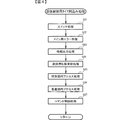
まず、主基板11における主要な動作を説明する。パチンコ遊技機1に対して電力供給が開始されると、遊技制御用マイクロコンピュータ100が起動し、CPU103によって遊技制御メイン処理が実行される。図3は、主基板11におけるCPU103が実行する遊技制御メイン処理を示すフローチャートである。
(Main operation of the main board 11)
First, main operations of the
図3に示す遊技制御メイン処理では、CPU103は、まず、割込禁止に設定する(ステップS1)。続いて、必要な初期設定を行う(ステップS2)。初期設定には、スタックポインタの設定、内蔵デバイス(CTC(カウンタ/タイマ回路)、パラレル入出力ポート等)のレジスタ設定、RAM102をアクセス可能状態にする設定等が含まれる。
In the game control main process shown in FIG. 3, the
次いで、クリアスイッチからの出力信号がオンであるか否かを判定する(ステップS3)。クリアスイッチは、例えば電源基板に搭載されている。クリアスイッチがオンの状態で電源が投入されると、出力信号(クリア信号)が入力ポートを介して遊技制御用マイクロコンピュータ100に入力される。クリアスイッチからの出力信号がオンである場合(ステップS3;Yes)、初期化処理(ステップS8)を実行する。初期化処理では、CPU103は、RAM102に記憶されるフラグ、カウンタ、バッファをクリアするRAMクリア処理を行い、作業領域に初期値を設定する。
Next, it is determined whether or not the output signal from the clear switch is on (step S3). The clear switch is mounted on, for example, a power supply board. When the power is turned on while the clear switch is on, an output signal (clear signal) is input to the
また、CPU103は、初期化を指示する演出制御コマンドを演出制御基板12に送信する(ステップS9)。演出制御用CPU120は、当該演出制御コマンドを受信すると、例えば画像表示装置5において、遊技機の制御の初期化がなされたことを報知するための画面表示を行う。
Further, the
クリアスイッチからの出力信号がオンでない場合には(ステップS3;No)、RAM102(バックアップRAM)にバックアップデータが保存されているか否かを判定する(ステップS4)。不測の停電等(電断)によりパチンコ遊技機1への電力供給が停止したときには、CPU103は、当該電力供給の停止によって動作できなくなる直前に、電源供給停止時処理を実行する。この電源供給停止時処理では、RAM102にデータをバックアップすることを示すバックアップフラグをオンする処理、RAM102のデータ保護処理等が実行される。データ保護処理には、誤り検出符号(チェックサム、パリティビット等)の付加、各種データをバックアップする処理が含まれる。バックアップされるデータには、遊技を進行するための各種データ(各種フラグ、各種タイマの状態等を含む)の他、前記バックアップフラグの状態や誤り検出符号も含まれる。ステップS4では、バックアップフラグがオンであるか否かを判定する。バックアップフラグがオフでRAM102にバックアップデータが記憶されていない場合(ステップS4;No)、初期化処理(ステップS8)を実行する。
If the output signal from the clear switch is not on (step S3; No), it is determined whether or not backup data is stored in the RAM 102 (backup RAM) (step S4). When the power supply to the
RAM102にバックアップデータが記憶されている場合(ステップS4;Yes)、CPU103は、バックアップしたデータのデータチェックを行い(誤り検出符号を用いて行われる)、データが正常か否かを判定する(ステップS5)。ステップS5では、例えば、パリティビットやチェックサムにより、RAM102のデータが、電力供給停止時のデータと一致するか否かを判定する。これらが一致すると判定された場合、RAM102のデータが正常であると判定する。
When the backup data is stored in the RAM 102 (Step S4; Yes), the
RAM102のデータが正常でないと判定された場合(ステップS5;No)、内部状態を電力供給停止時の状態に戻すことができないので、初期化処理(ステップS8)を実行する。
If it is determined that the data in the
RAM102のデータが正常であると判定された場合(ステップS5;Yes)、CPU103は、主基板11の内部状態を電力供給停止時の状態に戻すための復旧処理(ステップS6)を行う。復旧処理では、CPU103は、RAM102の記憶内容(バックアップしたデータの内容)に基づいて作業領域の設定を行う。これにより、電力供給停止時の遊技状態に復旧し、特別図柄の変動中であった場合には、後述の遊技制御用タイマ割込み処理の実行によって、復旧前の状態から特別図柄の変動が再開されることになる。
When it is determined that the data in the
そして、CPU103は、電断からの復旧を指示する演出制御コマンドを演出制御基板12に送信する(ステップS7)。これに合わせて、バックアップされている電断前の遊技状態を指定する演出制御コマンドや、特図ゲームの実行中であった場合には当該実行中の特図ゲームの表示結果を指定する演出制御コマンドを送信するようにしてもよい。これらコマンドは、後述の特別図柄プロセス処理で送信設定されるコマンドと同じコマンドを使用できる。演出制御用CPU120は、電断からの復旧時を特定する演出制御コマンドを受信すると、例えば画像表示装置5において、電断からの復旧がなされたこと又は電断からの復旧中であることを報知するための画面表示を行う。演出制御用CPU120は、前記演出制御コマンドに基づいて、適宜の画面表示を行うようにしてもよい。
Then, the
復旧処理または初期化処理を終了して演出制御基板12に演出制御コマンドを送信した後には、CPU103は、乱数回路104を初期設定する乱数回路設定処理を実行する(ステップS10)。そして、所定時間(例えば2ms)毎に定期的にタイマ割込がかかるように遊技制御用マイクロコンピュータ100に内蔵されているCTCのレジスタの設定を行い(ステップS11)、割込みを許可する(ステップS12)。その後、ループ処理に入る。以後、所定時間(例えば2ms)ごとにCTCから割込み要求信号がCPU103へ送出され、CPU103は定期的にタイマ割込み処理を実行することができる。
After transmitting the effect control command to the
こうした遊技制御メイン処理を実行したCPU103は、CTCからの割込み要求信号を受信して割込み要求を受け付けると、図4のフローチャートに示す遊技制御用タイマ割込み処理を実行する。図4に示す遊技制御用タイマ割込み処理を開始すると、CPU103は、まず、所定のスイッチ処理を実行することにより、スイッチ回路110を介してゲートスイッチ21、第1始動口スイッチ22A、第2始動口スイッチ22B、カウントスイッチ23といった各種スイッチからの検出信号の受信の有無を判定する(ステップS21)。続いて、所定のメイン側エラー処理を実行することにより、パチンコ遊技機1の異常診断を行い、その診断結果に応じて必要ならば警告を発生可能とする(ステップS22)。この後、所定の情報出力処理を実行することにより、例えばパチンコ遊技機1の外部に設置されたホール管理用コンピュータに供給される大当り情報(大当りの発生回数等を示す情報)、始動情報(始動入賞の回数等を示す情報)、確率変動情報(確変状態となった回数等を示す情報)などのデータを出力する(ステップS23)。
Upon receiving the interrupt request signal from the CTC and receiving the interrupt request, the
情報出力処理に続いて、主基板11の側で用いられる遊技用乱数の少なくとも一部をソフトウェアにより更新するための遊技用乱数更新処理を実行する(ステップS24)。この後、CPU103は、特別図柄プロセス処理を実行する(ステップS25)。CPU103がタイマ割込み毎に特別図柄プロセス処理を実行することにより、特図ゲームの実行及び保留の管理や、大当り遊技状態や小当り遊技状態の制御、遊技状態の制御などが実現される(詳しくは後述)。
Subsequent to the information output process, a game random number updating process for updating at least a part of the game random number used on the
特別図柄プロセス処理に続いて、普通図柄プロセス処理が実行される(ステップS26)。CPU103がタイマ割込み毎に普通図柄プロセス処理を実行することにより、ゲートスイッチ21からの検出信号に基づく(通過ゲート41に遊技球が通過したことに基づく)普図ゲームの実行及び保留の管理や、「普図当り」に基づく可変入賞球装置6Bの開放制御などを可能にする。普図ゲームの実行は、普通図柄表示器20を駆動することにより行われ、普図保留表示器25Cを点灯させることにより普図保留数を表示する。
Subsequent to the special symbol processing, the ordinary symbol processing is executed (step S26). The
普通図柄プロセス処理を実行した後、遊技制御用タイマ割込み処理の一部として、電断が発生したときの処理、賞球を払い出すための処理等などが行われてもよい。その後、CPU103は、コマンド制御処理を実行する(ステップS27)。CPU103は、上記各処理にて演出制御コマンドを送信設定することがある。ステップS27のコマンド制御処理では、送信設定された演出制御コマンドを演出制御基板12などのサブ側の制御基板に対して伝送させる処理が行われる。コマンド制御処理を実行した後には、割込みを許可してから、遊技制御用タイマ割込み処理を終了する。
After executing the normal symbol process process, a process when a power failure occurs, a process for paying out prize balls, and the like may be performed as part of the game control timer interrupt process. Thereafter, the
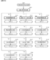
図5は、特別図柄プロセス処理として、図4に示すステップS25にて実行される処理の一例を示すフローチャートである。この特別図柄プロセス処理において、CPU103は、まず、始動入賞判定処理を実行する(ステップS101)。
FIG. 5 is a flowchart showing an example of a process executed in step S25 shown in FIG. 4 as a special symbol process process. In this special symbol process process, the
始動入賞判定処理では、始動入賞の発生を検出し、RAM102の所定領域に保留情報を格納し保留記憶数を更新する処理が実行される。始動入賞が発生すると、表示結果(大当り種別を含む)や変動パターンを決定するための乱数値が抽出され、保留情報として記憶される。また、抽出した乱数値に基づいて、表示結果や変動パターンを先読み判定する処理が実行されてもよい。保留情報や保留記憶数を記憶した後には、演出制御基板12に始動入賞の発生、保留記憶数、先読み判定等の判定結果を指定するための演出制御コマンドを送信するための送信設定が行われる。こうして送信設定された始動入賞時の演出制御コマンドは、例えば特別図柄プロセス処理が終了した後、図4に示すステップS27のコマンド制御処理が実行されることなどにより、主基板11から演出制御基板12に対して伝送される。
In the start winning prize determination process, a process of detecting occurrence of a start winning prize, storing the hold information in a predetermined area of the
S101にて始動入賞判定処理を実行した後、CPU103は、RAM102に設けられた特図プロセスフラグの値に応じて、ステップS110〜S120の処理のいずれかを選択して実行する。なお、特別図柄プロセス処理の各処理(ステップS110〜S120)では、各処理に対応した演出制御コマンドを演出制御基板12に送信するための送信設定が行われる。
After executing the start winning determination processing in S101, the
ステップS110の特別図柄通常処理は、特図プロセスフラグの値が“0”(初期値)のときに実行される。この特別図柄通常処理では、保留情報の有無などに基づいて、第1特図ゲーム又は第2特図ゲームを開始するか否かの判定が行われる。また、特別図柄通常処理では、表示結果決定用の乱数値に基づき、特別図柄や飾り図柄の表示結果を「大当り」または「小当り」とするか否かや「大当り」とする場合の大当り種別を、その表示結果が導出表示される以前に決定(事前決定)する。さらに、特別図柄通常処理では、決定された表示結果に対応して、特図ゲームにおいて停止表示させる確定特別図柄(大当り図柄や小当り図柄、ハズレ図柄のいずれか)が設定される。その後、特図プロセスフラグの値が“1”に更新され、特別図柄通常処理は終了する。なお、第2特図を用いた特図ゲームが第1特図を用いた特図ゲームよりも優先して実行されるようにしてもよい(特図2優先消化ともいう)。また、第1始動入賞口及び第2始動入賞口への遊技球の入賞順序を記憶し、入賞順に特図ゲームの開始条件を成立させるようにしてもよい(入賞順消化ともいう)。 The special symbol normal processing in step S110 is executed when the value of the special figure process flag is “0” (initial value). In this special symbol normal processing, it is determined whether to start the first special figure game or the second special figure game based on the presence or absence of the hold information. Also, in the special symbol normal processing, based on the random number value for determining the display result, whether the display result of the special symbol or decorative symbol is "big hit" or "small hit", and the big hit type in the case of "big hit" Is determined (predetermined) before the display result is derived and displayed. Further, in the special symbol normal process, a fixed special symbol (any of a big hit symbol, a small hit symbol, or a lost symbol) to be stopped and displayed in the special symbol game is set in accordance with the determined display result. Thereafter, the value of the special figure process flag is updated to “1”, and the special special pattern normal processing ends. Note that the special figure game using the second special figure may be executed prior to the special figure game using the first special figure (also referred to as special figure 2 priority digestion). Further, the order of winning the game balls to the first starting winning opening and the second starting winning opening may be stored, and the start condition of the special figure game may be established in the order of the winning (also referred to as winning order).
乱数値に基づき各種の決定を行う場合には、ROM101に格納されている各種のテーブル(乱数値と比較される決定値が決定結果に割り当てられているテーブル)が参照される。主基板11における他の決定、演出制御基板12における各種の決定についても同じである。演出制御基板12においては、各種のテーブルがROM121に格納されている。
When making various decisions based on random numbers, various tables stored in the ROM 101 (tables in which decision values to be compared with random numbers are assigned to decision results) are referred to. The same applies to other decisions made on the
ステップS111の変動パターン設定処理は、特図プロセスフラグの値が“1”のときに実行される。この変動パターン設定処理には、表示結果を「大当り」または「小当り」とするか否かの事前決定結果等に基づき、変動パターン決定用の乱数値を用いて変動パターンを複数種類のいずれかに決定する処理などが含まれている。変動パターン設定処理では、変動パターンを決定したときに、特図プロセスフラグの値が“2”に更新され、変動パターン設定処理は終了する。 The variation pattern setting process of step S111 is executed when the value of the special figure process flag is “1”. In this variation pattern setting process, any one of a plurality of types of variation patterns is determined by using a random value for determining a variation pattern based on a result of a predetermined determination as to whether the display result is “big hit” or “small hit”. And the like are determined. In the variation pattern setting process, when the variation pattern is determined, the value of the special figure process flag is updated to “2”, and the variation pattern setting process ends.
変動パターンは、特図ゲームの実行時間(特図変動時間)(飾り図柄の可変表示の実行時間でもある)や、飾り図柄の可変表示の態様(リーチの有無等)、飾り図柄の可変表示中の演出内容(リーチ演出の種類等)を指定するものであり、可変表示パターンとも呼ばれる。 The fluctuation pattern is the execution time of the special figure game (the special figure fluctuation time) (also the execution time of the variable display of the decorative symbol), the mode of the variable display of the decorative symbol (whether or not there is reach, etc.), and the variable display of the decorative symbol. (Such as the type of reach effect) and is also referred to as a variable display pattern.
ステップS112の特別図柄変動処理は、特図プロセスフラグの値が“2”のときに実行される。この特別図柄変動処理には、第1特別図柄表示装置4Aや第2特別図柄表示装置4Bにおいて特別図柄を変動させるための設定を行う処理や、その特別図柄が変動を開始してからの経過時間を計測する処理などが含まれている。また、計測された経過時間が変動パターンに対応する特図変動時間に達したか否かの判定も行われる。そして、特別図柄の変動を開始してからの経過時間が特図変動時間に達したときには、特図プロセスフラグの値が“3”に更新され、特別図柄変動処理は終了する。
The special symbol change process in step S112 is executed when the value of the special figure process flag is “2”. The special symbol change processing includes a process of setting a special symbol to be changed in the first special
ステップS113の特別図柄停止処理は、特図プロセスフラグの値が“3”のときに実行される。この特別図柄停止処理には、第1特別図柄表示装置4Aや第2特別図柄表示装置4Bにて特別図柄の変動を停止させ、特別図柄の表示結果となる確定特別図柄を停止表示(導出)させるための設定を行う処理が含まれている。そして、表示結果が「大当り」である場合には特図プロセスフラグの値が“4”に更新される。その一方で、大当りフラグがオフであり、表示結果が「小当り」である場合には、特図プロセスフラグの値が“8”に更新される。また、表示結果が「ハズレ」である場合には、特図プロセスフラグの値が“0”に更新される。表示結果が「小当り」又は「ハズレ」である場合、時短状態や確変状態に制御されているときであって、回数切りの終了成立する場合には、遊技状態も更新される。特図プロセスフラグの値が更新されると、特別図柄停止処理は終了する。
The special symbol stop processing in step S113 is executed when the value of the special figure process flag is “3”. In this special symbol stop processing, the change of the special symbol is stopped by the first special
ステップS114の大当り開放前処理は、特図プロセスフラグの値が“4”のときに実行される。この大当り開放前処理には、表示結果が「大当り」となったことなどに基づき、大当り遊技状態においてラウンドの実行を開始して大入賞口を開放状態とするための設定を行う処理などが含まれている。大入賞口を開放状態とするときには、大入賞口扉用のソレノイド82に対してソレノイド駆動信号を供給する処理が実行される。このときには、例えば大当り種別がいずれであるかに対応して、大入賞口を開放状態とする開放上限期間や、ラウンドの上限実行回数を設定する。これらの設定が終了すると、特図プロセスフラグの値が“5”に更新され、大当り開放前処理は終了する。
The big hit opening pre-processing of step S114 is executed when the value of the special figure process flag is “4”. The big hit opening pre-processing includes, for example, a process of starting a round in the big hit gaming state and setting a big winning opening to an open state based on a display result of “big hit” or the like. Have been. When opening the special winning opening, a process of supplying a solenoid drive signal to the
ステップS115の大当り開放中処理は、特図プロセスフラグの値が“5”のときに実行される。この大当り開放中処理には、大入賞口を開放状態としてからの経過時間を計測する処理や、その計測した経過時間やカウントスイッチ23によって検出された遊技球の個数などに基づいて、大入賞口を開放状態から閉鎖状態に戻すタイミングとなったか否かを判定する処理などが含まれている。そして、大入賞口を閉鎖状態に戻すときには、大入賞口扉用のソレノイド82に対するソレノイド駆動信号の供給を停止させる処理などを実行した後、特図プロセスフラグの値が“6”に更新し、大当り開放中処理を終了する。
The big hit opening processing in step S115 is executed when the value of the special figure process flag is “5”. The processing during the opening of the jackpot is based on a process of measuring the elapsed time from the opening of the jackpot, and on the basis of the measured elapsed time, the number of game balls detected by the
ステップS116の大当り開放後処理は、特図プロセスフラグの値が“6”のときに実行される。この大当り開放後処理には、大入賞口を開放状態とするラウンドの実行回数が設定された上限実行回数に達したか否かを判定する処理や、上限実行回数に達した場合に大当り遊技状態を終了させるための設定を行う処理などが含まれている。そして、ラウンドの実行回数が上限実行回数に達していないときには、特図プロセスフラグの値が“5”に更新される一方、ラウンドの実行回数が上限実行回数に達したときには、特図プロセスフラグの値が“7”に更新される。特図プロセスフラグの値が更新されると、大当り解放後処理は終了する。 The post-big hit release processing in step S116 is executed when the value of the special figure process flag is "6". The post-big hit opening process includes a process of determining whether or not the number of rounds in which the large winning opening is opened has reached a set upper limit number of times, and a process of determining whether or not the number of hits has reached the upper limit number of times. And the like to make settings for ending the process. When the number of rounds has not reached the upper limit execution number, the value of the special figure process flag is updated to “5”. The value is updated to "7". When the value of the special figure process flag is updated, the post-jackpot release processing ends.
ステップS117の大当り終了処理は、特図プロセスフラグの値が“7”のときに実行される。この大当り終了処理には、大当り遊技状態の終了を報知する演出動作としてのエンディング演出が実行される期間に対応した待ち時間が経過するまで待機する処理や、大当り遊技状態の終了に対応して確変制御や時短制御を開始するための各種の設定を行う処理などが含まれている。こうした設定が行われたときには、特図プロセスフラグの値が“0”に更新され、大当り終了処理は終了する。 The big hit end processing in step S117 is executed when the value of the special figure process flag is “7”. The big hit end process includes a process of waiting until a waiting time corresponding to a period during which an ending effect is performed as an effect operation for notifying the end of the big hit game state, and a change in response to the end of the big hit game state. Processing for performing various settings for starting control and time-saving control is included. When such a setting is made, the value of the special figure process flag is updated to “0”, and the big hit end processing ends.
ステップS118の小当り開放前処理は、特図プロセスフラグの値が“8”のときに実行される。この小当り開放前処理には、表示結果が「小当り」となったことに基づき、小当り遊技状態において大入賞口を開放状態とするための設定を行う処理などが含まれている。このときには、特図プロセスフラグの値が“9”に更新され、小当り開放前処理は終了する。 The small hit release pre-processing of step S118 is executed when the value of the special figure process flag is “8”. The small hit opening pre-processing includes, for example, a process of setting the large winning opening to the open state in the small hit gaming state based on the display result being “small hit”. At this time, the value of the special figure process flag is updated to “9”, and the small hit release pre-processing ends.
ステップS119の小当り開放中処理は、特図プロセスフラグの値が“9”のときに実行される。この小当り開放中処理には、大入賞口を開放状態としてからの経過時間を計測する処理や、その計測した経過時間などに基づいて、大入賞口を開放状態から閉鎖状態に戻すタイミングとなったか否かを判定する処理などが含まれている。大入賞口を閉鎖状態に戻して小当り遊技状態の終了タイミングとなったときには、特図プロセスフラグの値が“10”に更新され、小当り開放中処理は終了する。 The small hit opening processing in step S119 is executed when the value of the special figure process flag is "9". The processing during opening of the small hits includes processing for measuring the elapsed time from the opening of the special winning opening and timing for returning the special winning opening from the open state to the closed state based on the measured elapsed time. It includes a process of determining whether or not the event has occurred. When the big winning port is returned to the closed state and the timing of ending the small hitting game state is reached, the value of the special figure process flag is updated to “10”, and the small hit opening processing ends.
ステップS120の小当り終了処理は、特図プロセスフラグの値が“10”のときに実行される。この小当り終了処理には、小当り遊技状態の終了を報知する演出動作が実行される期間に対応した待ち時間が経過するまで待機する処理などが含まれている。ここで、小当り遊技状態が終了するときには、小当り遊技状態となる以前のパチンコ遊技機1における遊技状態を継続させる。小当り遊技状態の終了時における待ち時間が経過したときには、特図プロセスフラグの値が“0”に更新され、小当り終了処理は終了する。
The small hit end processing in step S120 is executed when the value of the special figure process flag is “10”. The small hit ending process includes a process of waiting until a waiting time corresponding to a period during which the effect operation for notifying the end of the small hit gaming state is executed is performed. Here, when the small hitting game state ends, the gaming state in the
(演出制御基板12の主要な動作)
次に、演出制御基板12における主要な動作を説明する。演出制御基板12では、電源基板等から電源電圧の供給を受けると、演出制御用CPU120が起動して、図6のフローチャートに示すような演出制御メイン処理を実行する。図6に示す演出制御メイン処理を開始すると、演出制御用CPU120は、まず、所定の初期化処理を実行して(ステップS71)、RAM122のクリアや各種初期値の設定、また演出制御基板12に搭載されたCTC(カウンタ/タイマ回路)のレジスタ設定等を行う。また、初期動作制御処理を実行する(ステップS72)。初期動作制御処理では、可動体32を駆動して初期位置に戻す制御、所定の動作確認を行う制御といった可動体32の初期動作を行う制御が実行される。
(Main operation of effect control board 12)
Next, main operations of the
その後、タイマ割込みフラグがオンとなっているか否かの判定を行う(ステップS73)。タイマ割込みフラグは、例えばCTCのレジスタ設定に基づき、所定時間(例えば2ミリ秒)が経過するごとにオン状態にセットされる。このとき、タイマ割込みフラグがオフであれば(ステップS73;No)、ステップS73の処理を繰り返し実行して待機する。 Thereafter, it is determined whether or not the timer interrupt flag is turned on (step S73). The timer interrupt flag is set to an on state each time a predetermined time (for example, 2 milliseconds) elapses based on, for example, a register setting of the CTC. At this time, if the timer interrupt flag is off (step S73; No), the process of step S73 is repeatedly executed and the process stands by.
また、演出制御基板12の側では、所定時間が経過するごとに発生するタイマ割込みとは別に、主基板11からの演出制御コマンドを受信するための割込みが発生する。この割込みは、例えば主基板11からの演出制御INT信号がオン状態となることにより発生する割込みである。演出制御INT信号がオン状態となることによる割込みが発生すると、演出制御用CPU120は、自動的に割込み禁止に設定するが、自動的に割込み禁止状態にならないCPUを用いている場合には、割込み禁止命令(DI命令)を発行することが望ましい。演出制御用CPU120は、演出制御INT信号がオン状態となることによる割込みに対応して、例えば所定のコマンド受信割込み処理を実行する。このコマンド受信割込み処理では、I/O125に含まれる入力ポートのうちで、中継基板15を介して主基板11から送信された制御信号を受信する所定の入力ポートより、演出制御コマンドを取り込む。このとき取り込まれた演出制御コマンドは、例えばRAM122に設けられた演出制御コマンド受信用バッファに格納する。その後、演出制御用CPU120は、割込み許可に設定してから、コマンド受信割込み処理を終了する。
In addition, on the side of the
ステップS73にてタイマ割込みフラグがオンである場合には(ステップS73;Yes)、タイマ割込みフラグをクリアしてオフ状態にするとともに(ステップS74)、コマンド解析処理を実行する(ステップS75)。コマンド解析処理では、例えば主基板11の遊技制御用マイクロコンピュータ100から送信されて演出制御コマンド受信用バッファに格納されている各種の演出制御コマンドを読み出した後に、その読み出された演出制御コマンドに対応した設定や制御などが行われる。例えば、どの演出制御コマンドを受信したかや演出制御コマンドが特定する内容等を演出制御プロセス処理等で確認できるように、読み出された演出制御コマンドをRAM122の所定領域に格納したり、RAM122に設けられた受信フラグをオンしたりする。また、演出制御コマンドが遊技状態を特定する場合、遊技状態に応じた背景の表示を表示制御部123に指示してもよい。
If the timer interrupt flag is on in step S73 (step S73; Yes), the timer interrupt flag is cleared and turned off (step S74), and a command analysis process is executed (step S75). In the command analysis process, for example, after reading various effect control commands transmitted from the
ステップS75にてコマンド解析処理を実行した後には、演出制御プロセス処理を実行する(ステップS76)。演出制御プロセス処理では、例えば画像表示装置5の表示領域における演出画像の表示動作、スピーカ8L、8Rからの音声出力動作、遊技効果ランプ9及び装飾用LEDといった装飾発光体における点灯動作、可動体32の駆動動作といった、各種の演出装置を動作させる制御が行われる。また、各種の演出装置を用いた演出動作の制御内容について、主基板11から送信された演出制御コマンド等に応じた判定や決定、設定などが行われる。
After executing the command analysis processing in step S75, the effect control process processing is executed (step S76). In the effect control process processing, for example, a display operation of an effect image in a display area of the
ステップS76の演出制御プロセス処理に続いて、演出用乱数更新処理が実行され(ステップS77)、演出制御基板12の側で用いられる演出用乱数の少なくとも一部がソフトウェアにより更新される。その後、ステップS73の処理に戻る。ステップS73の処理に戻る前に、他の処理が実行されてもよい。
Following the effect control process in step S76, an effect random number update process is executed (step S77), and at least a part of the effect random number used on the
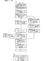
図7は、演出制御プロセス処理として、図6のステップS76にて実行される処理の一例を示すフローチャートである。図7に示す演出制御プロセス処理において、演出制御用CPU120は、まず、先読予告設定処理を実行する(ステップS161)。先読予告設定処理では、例えば、主基板11から送信された始動入賞時の演出制御コマンドに基づいて、先読み予告演出を実行するための判定や決定、設定などが行われる。また、当該演出制御コマンドから特定される保留記憶数に基づき保留表示を表示するための処理が実行される。
FIG. 7 is a flowchart showing an example of the processing executed in step S76 of FIG. 6 as the effect control process processing. In the effect control process process shown in FIG. 7, the
ステップS161の処理を実行した後、演出制御用CPU120は、例えばRAM122に設けられた演出プロセスフラグの値に応じて、以下のようなステップS170〜S177の処理のいずれかを選択して実行する。
After executing the process of step S161, the
ステップS170の可変表示開始待ち処理は、演出プロセスフラグの値が“0”(初期値)のときに実行される処理である。この可変表示開始待ち処理は、主基板11から可変表示の開始を指定するコマンドなどを受信したか否かに基づき、画像表示装置5における飾り図柄の可変表示を開始するか否かを判定する処理などを含んでいる。画像表示装置5における飾り図柄の可変表示を開始すると判定された場合、演出プロセスフラグの値を“1”に更新し、可変表示開始待ち処理を終了する。
The variable display start waiting process in step S170 is a process executed when the value of the effect process flag is “0” (initial value). This variable display start waiting process is a process of determining whether or not to start the variable display of the decorative symbol on the
ステップS171の可変表示開始設定処理は、演出プロセスフラグの値が“1”のときに実行される処理である。この可変表示開始設定処理では、演出制御コマンドにより特定される表示結果や変動パターンに基づいて、飾り図柄の可変表示の表示結果(確定飾り図柄)、飾り図柄の可変表示の態様、リーチ演出や各種予告演出などの各種演出の実行の有無やその態様や実行開始タイミングなどを決定する。そして、その決定結果等を反映した演出制御パターン(表示制御部123に演出の実行を指示するための制御データの集まり)を設定する。その後、設定した演出制御パターンに基づいて、飾り図柄の可変表示の実行開始を表示制御部123に指示し、演出プロセスフラグの値を“2”に更新し、可変表示開始設定処理を終了する。表示制御部123は、飾り図柄の可変表示の実行開始の指示により、画像表示装置5において、飾り図柄の可変表示を開始させる。
The variable display start setting process in step S171 is a process executed when the value of the effect process flag is “1”. In the variable display start setting processing, based on the display result and the variation pattern specified by the effect control command, the display result of the variable display of the decorative symbol (fixed decorative symbol), the variable display mode of the decorative symbol, the reach Whether or not various effects such as a notice effect are to be executed, the mode thereof, the execution start timing, and the like are determined. Then, an effect control pattern (a set of control data for instructing the
ステップS172の可変表示中演出処理は、演出プロセスフラグの値が“2”のときに実行される処理である。この可変表示中演出処理において、演出制御用CPU120は、表示制御部123を指示することで、ステップS171にて設定された演出制御パターンに基づく演出画像を画像表示装置5の表示画面に表示させることや、可動体32を駆動させること、音声制御基板13に対する指令(効果音信号)の出力によりスピーカ8L、8Rから音声や効果音を出力させること、ランプ制御基板14に対する指令(電飾信号)の出力により遊技効果ランプ9や装飾用LEDを点灯/消灯/点滅させることといった、飾り図柄の可変表示中における各種の演出制御を実行する。こうした演出制御を行った後、例えば演出制御パターンから飾り図柄の可変表示終了を示す終了コードが読み出されたこと、あるいは、主基板11から確定飾り図柄を停止表示させることを指定するコマンドを受信したことなどに対応して、飾り図柄の表示結果となる確定飾り図柄を停止表示させる。確定飾り図柄を停止表示したときには、演出プロセスフラグの値が“3”に更新され、可変表示中演出処理は終了する。
The variable display effect processing in step S172 is processing executed when the value of the effect process flag is “2”. In the variable display effect processing, the
ステップS173の特図当り待ち処理は、演出プロセスフラグの値が“3”のときに実行される処理である。この特図当り待ち処理において、演出制御用CPU120は、主基板11から大当り遊技状態又は小当り遊技状態を開始することを指定する演出制御コマンドの受信があったか否かを判定する。そして、大当り遊技状態又は小当り遊技状態を開始することを指定する演出制御コマンドを受信したきに、そのコマンドが大当り遊技状態の開始を指定するものであれば、演出プロセスフラグの値を“6”に更新する。これに対して、そのコマンドが小当り遊技状態の開始を指定するものであれば、演出プロセスフラグの値を小当り中演出処理に対応した値である“4”に更新する。また、大当り遊技状態又は小当り遊技状態を開始することを指定するコマンドを受信せずに、当該コマンドの受信待ち時間が経過したときには、特図ゲームにおける表示結果が「ハズレ」であったと判定して、演出プロセスフラグの値を初期値である“0”に更新する。演出プロセスフラグの値を更新すると、特図当り待ち処理を終了する。
The wait process per special figure in step S173 is a process executed when the value of the effect process flag is “3”. In this special figure waiting process, the
ステップS174の小当り中演出処理は、演出制御プロセスフラグの値が“4”のときに実行される処理である。この小当り中演出処理において、演出制御用CPU120は、例えば小当り遊技状態における演出内容に対応した演出制御パターン等を設定し、その設定内容に基づく小当り遊技状態における各種の演出制御を実行する。また、小当り中演出処理では、例えば主基板11から小当り遊技状態を終了することを指定するコマンドを受信したことに対応して、演出プロセスフラグの値を小当り終了演出に対応した値である“5”に更新し、小当り中演出処理を終了する。
The small hit production process in step S174 is a process executed when the value of the production control process flag is “4”. In the small hit effect production process, the
ステップS175の小当り終了演出処理は、演出制御プロセスフラグの値が“5”のときに実行される処理である。この小当り終了演出処理において、演出制御用CPU120は、例えば小当り遊技状態の終了などに対応した演出制御パターン等を設定し、その設定内容に基づく小当り遊技状態の終了時における各種の演出制御を実行する。その後、演出プロセスフラグの値を初期値である“0”に更新し、小当り終了演出処理を終了する。
The small hit end effect process in step S175 is a process executed when the value of the effect control process flag is “5”. In the small hit end effect processing, the
ステップS176の大当り中演出処理は、演出プロセスフラグの値が“6”のときに実行される処理である。この大当り中演出処理において、演出制御用CPU120は、例えば大当り遊技状態における演出内容に対応した演出制御パターン等を設定し、その設定内容に基づく大当り遊技状態における各種の演出制御を実行する。また、大当り中演出処理では、例えば主基板11から大当り遊技状態を終了することを指定するコマンドを受信したことに対応して、演出制御プロセスフラグの値をエンディング演出処理に対応した値である“7”に更新し、大当り中演出処理を終了する。
The big hit production process in step S176 is a process executed when the value of the production process flag is “6”. In this big hit effect processing, the
ステップS177のエンディング演出処理は、演出プロセスフラグの値が“7”のときに実行される処理である。このエンディング演出処理において、演出制御用CPU120は、例えば大当り遊技状態の終了などに対応した演出制御パターン等を設定し、その設定内容に基づく大当り遊技状態の終了時におけるエンディング演出の各種の演出制御を実行する。その後、演出プロセスフラグの値を初期値である“0”に更新し、エンディング演出処理を終了する。
The ending effect process of step S177 is a process executed when the value of the effect process flag is “7”. In the ending effect processing, the
(基本説明の変形例)
この発明は、上記基本説明で説明したパチンコ遊技機1に限定されず、本発明の趣旨を逸脱しない範囲で、様々な変形及び応用が可能である。
(Modification of the basic description)
The present invention is not limited to the
上記基本説明のパチンコ遊技機1は、入賞の発生に基づいて所定数の遊技媒体を景品として払い出す払出式遊技機であったが、遊技媒体を封入し入賞の発生に基づいて得点を付与する封入式遊技機であってもよい。
The
特別図柄の可変表示中に表示されるものは1種類の図柄(例えば、「−」を示す記号)だけで、当該図柄の表示と消灯とを繰り返すことによって可変表示を行うようにしてもよい。さらに可変表示中に当該図柄が表示されるものも、可変表示の停止時には、当該図柄が表示されなくてもよい(表示結果としては「−」を示す記号が表示されなくてもよい)。 Only one type of symbol (for example, a symbol indicating "-") is displayed during the variable display of the special symbol, and the variable display may be performed by repeatedly displaying and extinguishing the symbol. Further, when the symbol is displayed during the variable display, the symbol may not be displayed when the variable display is stopped (the sign indicating “−” may not be displayed as a display result).
上記基本説明では、遊技機としてパチンコ遊技機1を示したが、メダルが投入されて所定の賭け数が設定され、遊技者による操作レバーの操作に応じて複数種類の図柄を回転させ、遊技者によるストップボタンの操作に応じて図柄を停止させたときに停止図柄の組合せが特定の図柄の組み合わせになると、所定数のメダルが遊技者に払い出されるゲームを実行可能なスロット機(例えば、ビッグボーナス、レギュラーボーナス、RT、AT、ART、CZ(以下、ボーナス等)のうち1以上を搭載するスロット機)にも本発明を適用可能である。
In the above basic description, the
本発明を実現するためのプログラム及びデータは、パチンコ遊技機1に含まれるコンピュータ装置などに対して、着脱自在の記録媒体により配布・提供される形態に限定されるものではなく、予めコンピュータ装置などの有する記憶装置にインストールしておくことで配布される形態を採っても構わない。さらに、本発明を実現するためのプログラム及びデータは、通信処理部を設けておくことにより、通信回線等を介して接続されたネットワーク上の、他の機器からダウンロードすることによって配布する形態を採っても構わない。
The program and data for realizing the present invention are not limited to a form that is distributed and provided to a computer device or the like included in the
そして、ゲームの実行形態も、着脱自在の記録媒体を装着することにより実行するものだけではなく、通信回線等を介してダウンロードしたプログラム及びデータを、内部メモリ等に一旦格納することにより実行可能とする形態、通信回線等を介して接続されたネットワーク上における、他の機器側のハードウェア資源を用いて直接実行する形態としてもよい。さらには、他のコンピュータ装置等とネットワークを介してデータの交換を行うことによりゲームを実行するような形態とすることもできる。 The game can be executed not only by installing a removable recording medium, but also by temporarily storing a program and data downloaded via a communication line or the like in an internal memory or the like. Alternatively, the program may be directly executed using hardware resources of another device on a network connected via a communication line or the like. Furthermore, the game may be executed by exchanging data with another computer device or the like via a network.
なお、本明細書において、演出の実行割合などの各種割合の比較の表現(「高い」、「低い」、「異ならせる」などの表現)は、一方が「0%」の割合であることを含んでもよい。例えば、一方が「0%」の割合で、他方が「100%」の割合又は「100%」未満の割合であることも含む。 In the present specification, the expression of comparison of various ratios such as the execution ratio of an effect (expressions such as “high”, “low”, and “different”) indicates that one of them is a ratio of “0%”. May be included. For example, it may also include that one is a ratio of “0%” and the other is a ratio of “100%” or a ratio of less than “100%”.
(特徴部の説明)
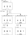
次に本実施の形態における特徴部について説明する。図8−1は、本実施の形態における画像表示装置5の正面図である。図8−1に示すように、本実施の形態における画像表示装置5の表示領域の下部の左右2箇所には、第1保留記憶表示エリア81SG5D、第2保留記憶表示エリア81SG5Uが設定されている。第1保留記憶表示エリア81SG5D、第2保留記憶表示エリア81SG5Uでは、特図ゲームに対応した可変表示の保留記憶数(特図保留記憶数)を特定可能に表示する保留表示が行われる。また、画像表示装置5の下部における左右方向の中央には、変動表示中の保留記憶に対応する保留表示をアクティブ表示として表示するアクティブ表示エリア81SG5Fが表示されている。
(Description of features)
Next, the characteristic part in the present embodiment will be described. FIG. 8A is a front view of the
ここで、特図ゲームに対応した可変表示の保留は、入賞球装置6Aが形成する第1始動入賞口や、可変入賞球装置6Bが形成する第2始動入賞口を、遊技球が通過(進入)することによる始動入賞に基づいて発生する。即ち、特図ゲームや飾り図柄の変動表示といった可変表示ゲームを実行するための始動条件(「実行条件」ともいう)は成立したが、先に成立した開始条件に基づく可変表示ゲームが実行中であることやパチンコ遊技機1が大当り遊技状態に制御されていることなどにより、可変表示ゲームの開始を許容する開始条件が成立していないときに、成立した始動条件に対応する可変表示の保留が行われる。本実施の形態では、第1始動入賞口を遊技球が通過(進入)することによる始動入賞に基づいて発生した保留表示を丸型の白色表示とし、第2始動入賞口を遊技球が通過(進入)することによる始動入賞に基づいて発生した保留表示を同様に丸型の白色表示とする。また、本実施の形態におけるアクティブ表示エリア81SG5Fは、各保留表示よりも表示面積の大きい半球状に形成されている。つまり、本実施の形態におけるアクティブ表示エリア81SG5Fは、画像表示装置5の下部において、左右方向の中央部に表示されているとともに、各保留表示よりも表示面積が大きいため、各保留表示よりも遊技者からの視認性が高くなっている。つまり、本実施例における視認性とは、遊技者からの視線による認識し易さを示している。このため、アクティブ表示エリア81SG5Fは、本実施の形態のように保留表示よりも大きいことや、保留表示よりも遊技者から視認されやすいに位置に表示されていること、保留表示よりも輝度が高いこと等を含んでいてもよい。
Here, the suspension of the variable display corresponding to the special figure game is such that the game ball passes (enters) the first starting winning opening formed by the winning
図8−2に示すように、演出制御基板12は、演出制御用CPU120、RAM122を含む演出制御用マイクロコンピュータ81SG81を搭載している。演出制御基板12において、演出制御用CPU120は、内蔵のROM121に格納されたプログラムに従って動作し、入力回路81SG260を介して演出制御コマンドを受信する。このうち、ROM121には、各種の演出におい画像表示装置5に表示する画像に関するデータや表示の開始タイミングや終了タイミング等のタイムチャート等が演出の種別毎に記憶されており、RAM122には、図示しないキャンセルカウンタが記憶されている。また、演出制御用CPU120は、演出制御コマンドにもとづいて、表示制御部123に、画像表示装置5に表示する画像の生成や図示しないバックライトの発光強度の調整等の表示制御を行わせる表示制御処理を実施する。
As shown in FIG. 8B, the
表示制御部123は、図8−2に示すように、スプライト画像として用いる画像要素データとしてのキャラクタ(人物、動物、文字、図形、記号等の画像データ、CGデータとも呼ぶ)などのデータが格納されるCGROM81SG205、フレームバッファ領域81SG501(VRAM領域、図8−24参照)として使用されるSDRAM81SG210(シンクロナスDRAM)とともに表示制御回路を構成する。
As shown in FIG. 8B, the
演出制御用CPU120は、受信した演出制御コマンドに従って各種の画像データが記憶された画像データROM81SG263から必要なデータを読み出すための指令を表示制御部123に出力する。画像データROM81SG263は、画像表示装置5に表示されるキャラクタ画像データや動画像データ、具体的には、人物、文字、図形や記号等(飾り図柄を含む)、および背景画像の画像データをあらかじめ格納しておくためのROMである。表示制御部123は、演出制御用CPU120の指令に応じて、画像データROM81SG263から画像データを読み出す。そして、表示制御部123は、読み出した画像データにもとづいて表示制御を実行する。
The
表示制御部123は、表示制御部123の各種設定などが格納されるシステムレジスタ81SG202、アトリビュート(キャラクタを描画する際に使用されるパラメータであり、キャラクタの描画順序や、色数、拡大縮小率、パレット番号、座標などを指定するデータ)が格納されるアトリビュートレジスタ81SG203、フレームバッファ領域81SG501の後述する描画領域への画像の描画制御を行う描画制御部81SG206、CGROM81SG205に格納されているCGデータをフレームバッファ領域81SG501に転送する制御を行うデータ転送制御部81SG211、フレームバッファ領域81SG501の後述する表示領域に格納されている画像データを表示するためのビデオ信号(R(赤)、G(緑)、B(青))信号及び同期信号を出力する出力制御部81SG213、出力制御部81SG213から出力されたビデオ信号をアナログ信号に変換して画像表示装置5に出力するDAコンバータ81SG214などが搭載された集積回路である。
The
表示制御部123の内部には、システムバス、CGバスが設けられており、システムバス及びCGバスはCPUインターフェイス81SG201を介して演出制御用マイクロコンピュータ81SG81のCPU(演出制御用CPU120)と接続されているとともに、CGバスはCGバスインターフェイス81SG204を介してCGROM81SG205に接続されている。システムバスにはシステムレジスタ81SG202が接続されているとともに、CGバスにはアトリビュートレジスタ81SG203が接続されており、演出制御用CPU120は、システムレジスタ81SG202及びアトリビュートレジスタ81SG203にアクセスできるようになっている。
A system bus and a CG bus are provided inside the
また、描画制御部81SG206、データ転送制御部81SG211、出力制御部81SG213はシステムバスに接続されており、システムレジスタ81SG202にアクセスできるようになっている。また、描画制御部81SG206、データ転送制御部81SG211はCGバスに接続されており、CGROM81SG205、アトリビュートレジスタ81SG203にアクセスできるようになっている。 The drawing control unit 81SG206, the data transfer control unit 81SG211 and the output control unit 81SG213 are connected to a system bus, and can access the system register 81SG202. The drawing control unit 81SG206 and the data transfer control unit 81SG211 are connected to the CG bus, and can access the CGROM 81SG205 and the attribute register 81SG203.
また、表示制御部123の内部には、更にVRAMバスが設けられており、VRAMバスは、VRAMバスインターフェイス81SG209を介してSDRAM81SG210と接続されている。VRAMバスには、描画制御部81SG206、データ転送制御部81SG211、出力制御部81SG213が接続されており、VRAMバスを介してSDRAM81SG210のフレームバッファ領域81SG501にアクセスできるようになっている。
Further, a VRAM bus is further provided inside the
システムレジスタ81SG202には、初期設定、描画、データ転送などの命令を格納するシステム制御レジスタ、後述する割込信号の出力命令などを格納する割込制御レジスタ、フレームバッファ領域81SG501における描画領域、パレットデータの配置領域などを格納する描画レジスタ、データ転送時の転送元のアドレス、転送先のアドレスなどを格納するデータ転送レジスタ、フレームバッファ領域81SG501における表示領域などを格納する表示レジスタなどが割り当てられている。 The system register 81SG202 includes a system control register for storing commands such as initialization, drawing, and data transfer, an interrupt control register for storing an interrupt signal output command described later, a drawing area in the frame buffer area 81SG501, and palette data. , A data transfer register for storing a transfer source address and a transfer destination address for data transfer, a display register for storing a display area in the frame buffer area 81SG501, and the like. .
CPUインターフェイス81SG201は、Vブランク(画像を更新する周期)の開始毎に演出制御用CPU120に対してVブランク割込信号を出力するとともに、その他各種割込信号を、演出制御用CPU120に対して出力する。出力制御部81SG213は、表示レジスタにて指定されているフレームバッファ領域81SG501の画像データをビデオ信号として出力する表示処理を行う。
The CPU interface 81SG201 outputs a V blank interrupt signal to the
尚、SDRAM81SG210のフレームバッファ領域81SG501には、パレットデータが配置されるパレット領域、必要なキャラクタがCGROM81SG205から読み出されて格納されるキャラクタ用バッファ、描画制御部81SG206が画像を描画する際にパレットデータ(キャラクタの表示色が定義されたデータ)を一時的に保存するため、及び描画制御部81SG206が画像を描画する際にCGデータを一時的に保存するためのCG用バッファなどの各領域が割り当てられている。 In the frame buffer area 81SG501 of the SDRAM 81SG210, a pallet area in which pallet data is arranged, a character buffer in which necessary characters are read from the CGROM 81SG205 and stored, and pallet data when the drawing control unit 81SG206 draws an image. Each area such as a CG buffer for temporarily storing (data defining the display color of the character) and temporarily storing CG data when the drawing control unit 81SG206 draws an image is allocated. Has been.
また、フレームバッファ領域81SG501には、後述するように、画像表示装置5に表示される画像データが格納される第1描画領域(第1画像バッファ領域)、が割り当てられており、描画領域が、表示レジスタにて指定されることにより、描画領域に描画されて格納されている画像が画像表示装置5に表示される。
Further, as described later, a first drawing area (first image buffer area) for storing image data to be displayed on the
前述のように、演出制御用CPU120は、CPUインターフェイス81SG201を介してシステムレジスタ81SG202及びアトリビュートレジスタ81SG203にアクセスできるようになっており、前述した画像表示装置5の表示パターンを定めたプロセスデータに従ってこれらシステムレジスタ81SG202及びアトリビュートレジスタ81SG203に実行命令や必要なデータを格納することで、表示制御部123を間接的に制御する。
As described above, the
プロセスデータには、Vブランク毎に演出制御用CPU120がシステムレジスタ81SG202やアトリビュートレジスタ81SG203に対して行う設定内容が定められている。システムレジスタ81SG202の設定内容としては、描画、データ転送命令や、データ転送を行うCGデータやパレットデータ、アトリビュートの設定などがある。また、アトリビュートレジスタ81SG203の設定内容は、アトリビュート、すなわちキャラクタを描画する際に使用されるパラメータそのものである。
In the process data, the settings performed by the
また、プロセスデータには、Vブランク毎に画像の更新が行われるようにアトリビュートが設定されている。このため、画像の更新は、Vブランク毎に行われることとなる。 In the process data, attributes are set so that the image is updated for each V blank. Therefore, the image is updated every V blank.
ここで、描画制御について簡潔に説明する。描画制御部81SG206が描画処理を行うためには、描画に必要なキャラクタがフレームバッファ領域81SG501に配置されている必要がある。すなわちスプライト画像のソースデータとなるキャラクタをフレームバッファ領域81SG501に配置する必要がある。 Here, the drawing control will be briefly described. In order for the drawing control unit 81SG206 to perform the drawing process, it is necessary that characters necessary for drawing be arranged in the frame buffer area 81SG501. That is, it is necessary to arrange a character serving as source data of the sprite image in the frame buffer area 81SG501.
このため、演出制御用CPU120は、各種の演出を実行する際に、当該演出の実行に必要な全てのキャラクタのCGROM81SG205からフレームバッファ領域81SG501への転送命令を行う。これに伴いデータ転送制御部81SG211によって演出の実行に必要な全てのキャラクタがフレームバッファ領域81SG501に配置されることとなる。演出を実行する場合には、何度も繰り返して同じキャラクタを描画に用いることが多いが、CGROM81SG205に格納されたデータは圧縮されており、これを読み出すのに時間を要するので、前述のように演出を実行する最初の段階で、必要な全てのキャラクタをフレームバッファ領域81SG501に配置することにより、各フレーム毎にCGROM81SG205からデータを読み出すのに比較して描画に要する時間が少なくて済むこととなる。尚、本実施の形態では、演出制御用CPU120が演出を実行する際に、当該動画再生に必要な全てのキャラクタのCGROM81SG205からフレームバッファ領域81SG501への転送命令を行うようになっているが、描画に必要なキャラクタの転送命令をその都度行うようにしても良い。
For this reason, when performing various effects, the
また、描画制御部81SG206が描画処理を行うためには、アトリビュートレジスタ81SG203にアトリビュートが設定されている必要がある。アトリビュートは、Vブランク毎に異なるため、Vブランク毎にプロセスデータに従ったアトリビュートをアトリビュートレジスタ81SG203に格納する。 In addition, in order for the drawing control unit 81SG206 to perform a drawing process, an attribute must be set in the attribute register 81SG203. Since the attribute differs for each V blank, the attribute according to the process data is stored in the attribute register 81SG203 for each V blank.
そして、演出制御用CPU120は、演出を開始した後、Vブランク毎に、アトリビュートをアトリビュートレジスタ81SG203に設定した後、アトリビュートの読込の実行を命令する。これに伴い描画制御部81SG206は、アトリビュートレジスタ81SG203のアトリビュートを読み込んで、読込が終了すると読込終了割込信号の出力を命令する。これを受けて演出制御用CPU120は描画の実行を命令し、描画制御部81SG206は、読み込んだアトリビュートに従って描画領域に画像データの描画を行う。
After starting the effect, the
次に、本実施の形態において主基板11から演出制御基板12に出力される演出制御コマンドについて説明する。図8−3(A)は、本実施の形態で用いられる演出制御コマンドの内容の一例を示す説明図である。演出制御コマンドは、例えば2バイト構成であり、1バイト目はMODE(コマンドの分類)を示し、2バイト目はEXT(コマンドの種類)を表す。MODEデータの先頭ビット(ビット7)は必ず「1」とされ、EXTデータの先頭ビットは「0」とされる。尚、図8−3(A)に示されたコマンド形態は一例であって、他のコマンド形態を用いてもよい。また、この例では、制御コマンドが2つの制御信号で構成されることになるが、制御コマンドを構成する制御信号数は、1であってもよいし、3以上の複数であってもよい。
Next, an effect control command output from the
図8−3(A)に示す例において、コマンド8001Hは、第1特別図柄表示装置4Aにおける第1特図を用いた特図ゲームにおける変動開始を指定する第1変動開始コマンドである。コマンド8002Hは、第2特別図柄表示装置4Bにおける第2特図を用いた特図ゲームにおける変動開始を指定する第2変動開始コマンドである。コマンド81XXHは、特図ゲームにおける特別図柄の変動表示に対応して画像表示装置5における「左」、「中」、「右」の各飾り図柄表示エリア5L,5C,5Rで変動表示される飾り図柄などの変動パターン(変動時間)を指定する変動パターン指定コマンドである。ここで、XXHは不特定の16進数であることを示し、演出制御コマンドによる指示内容に応じて任意に設定される値であればよい。尚、変動パターン指定コマンドでは、指定する変動パターンなどに応じて、異なるEXTデータが設定される。
In the example shown in FIG. 8A, the command 8001H is a first variation start command for designating a variation start in a special figure game using the first special figure in the first special
コマンド8CXXHは、変動表示結果指定コマンドであり、特別図柄や飾り図柄などの変動表示結果を指定する演出制御コマンドである。変動表示結果指定コマンドでは、例えば図8−3(B)に示すように、変動表示結果が「ハズレ」であるか「大当り」であるかの決定結果(事前決定結果)や、変動表示結果が「大当り」となる場合の大当り種別を複数種類のいずれとするかの決定結果(大当り種別決定結果)に応じて、異なるEXTデータが設定される。 The command 8CXXH is a variable display result designation command, and is an effect control command for designating a variable display result such as a special symbol or a decorative symbol. In the variable display result designation command, for example, as shown in FIG. 8-3 (B), the result of determining whether the variable display result is “losing” or “big hit” (predetermined result) or the variable display result is Different EXT data is set in accordance with the result of determining which of the plurality of types is the big hit type in the case of "big hit" (big hit type determination result).
変動表示結果指定コマンドでは、例えば図8−3(B)に示すように、コマンド8C00Hは、変動表示結果が「ハズレ」となる旨の事前決定結果を示す第1変動表示結果指定コマンドである。コマンド8C01Hは、変動表示結果が「大当り」で大当り種別が「確変大当りA」となる旨の事前決定結果及び大当り種別決定結果を通知する第2変動表示結果指定コマンドである。コマンド8C02Hは、変動表示結果が「大当り」で大当り種別が「確変大当りB」となる旨の事前決定結果及び大当り種別決定結果を通知する第3変動表示結果指定コマンドである。コマンド8C03Hは、変動表示結果が「大当り」で大当り種別が「非確変大当り」となる旨の事前決定結果及び大当り種別決定結果を通知する第4変動表示結果指定コマンドである。 In the variable display result designation command, for example, as shown in FIG. 8C, the command 8C00H is a first variable display result designation command indicating a predetermined result indicating that the variable display result is “losing”. The command 8C01H is a second variable display result designation command for notifying a pre-determined result indicating that the variable display result is “big hit” and the big hit type is “probable variable big hit A” and the big hit type determination result. The command 8C02H is a third variable display result designation command for notifying the result of the preliminary determination that the variable display result is “big hit” and the big hit type is “probable variable big hit B” and the result of the big hit type determination. The command 8C03H is a fourth variable display result designation command for notifying of a pre-determined result indicating that the variable display result is "big hit" and the big hit type is "non-probable variable big hit" and a big hit type determination result.
コマンド8F00Hは、画像表示装置5における「左」、「中」、「右」の各飾り図柄表示エリア5L,5C,5Rで飾り図柄の変動停止(確定)を指定する図柄確定コマンドである。コマンド95XXHは、パチンコ遊技機1における現在の遊技状態を指定する遊技状態指定コマンドである。遊技状態指定コマンドでは、例えばパチンコ遊技機1における現在の遊技状態に応じて、異なるEXTデータが設定される。具体的な一例として、コマンド9500Hを時短制御と確変制御がいずれも行われない遊技状態(低確低ベース状態、通常状態)に対応した第1遊技状態指定コマンドとし、コマンド9501Hを時短制御が行われる一方で確変制御は行われない遊技状態(低確高ベース状態、時短状態)に対応した第2遊技状態指定コマンドとする。また、コマンド9502Hを確変制御が行われる一方で時短制御は行われない遊技状態(高確低ベース状態、時短なし確変状態)に対応した第3遊技状態指定コマンドとし、コマンド9503Hを時短制御と確変制御がともに行われる遊技状態(高確高ベース状態、時短付確変状態)に対応した第4遊技状態指定コマンドとする。
The command 8F00H is a symbol confirmation command for designating the stop (decision) of the decoration symbol in the “left”, “middle”, and “right” decoration
コマンドA0XXHは、大当り遊技状態の開始を示す演出画像の表示を指定する大当り開始指定コマンド(「ファンファーレコマンド」ともいう)である。コマンドA1XXHは、大当り遊技状態において、大入賞口が開放状態となっている期間であることを通知する大入賞口開放中通知コマンドである。コマンドA2XXHは、大当り遊技状態において、大入賞口が開放状態から閉鎖状態に変化した期間であることを通知する大入賞口開放後通知コマンドである。コマンドA3XXHは、大当り遊技状態の終了時における演出画像の表示を指定する大当り終了指定コマンドである。 The command A0XXH is a jackpot start designation command (also referred to as a “fanfare command”) for designating the display of an effect image indicating the start of the jackpot game state. The command A1XXH is a special winning opening opening notification command for notifying that the special winning opening is in the open state in the big hit gaming state. The command A2XXH is a notification command after the opening of the special winning opening that notifies that the special winning opening has changed from the open state to the closed state in the big hit gaming state. The command A3XXH is a big hit end designation command for designating the display of the effect image at the end of the big hit game state.
大当り開始指定コマンドや大当り終了指定コマンドでは、例えば変動表示結果指定コマンドと同様のEXTデータが設定されることなどにより、事前決定結果や大当り種別決定結果に応じて異なるEXTデータが設定されてもよい。あるいは、大当り開始指定コマンドや大当り終了指定コマンドでは、事前決定結果及び大当り種別決定結果と設定されるEXTデータとの対応関係を、変動表示結果指定コマンドにおける対応関係とは異ならせるようにしてもよい。大入賞口開放中通知コマンドや大入賞口開放後通知コマンドでは、例えば通常開放大当り状態や短期開放大当り状態におけるラウンドの実行回数(例えば「1」〜「16」)に対応して、異なるEXTデータが設定される。 In the big hit start specifying command and the big hit end specifying command, for example, different EXT data may be set according to the pre-determined result or the big hit type determining result by setting the same EXT data as the variable display result specifying command. . Alternatively, in the jackpot start designation command and the jackpot end designation command, the correspondence between the pre-determination result and the jackpot type determination result and the set EXT data may be different from the correspondence in the variable display result designation command. . The notification command during opening of the special winning opening and the notification command after opening of the special winning opening include different EXT data in accordance with the number of times of execution of the round (for example, “1” to “16”) in the normal opening big hit state and the short opening big hit state. Is set.
コマンドB100Hは、入賞球装置6Aが形成する第1始動入賞口を通過(進入)した遊技球が第1始動口スイッチ22Aにより検出されて始動入賞(第1始動入賞)が発生したことに基づき、第1特別図柄表示装置4Aにおける第1特図を用いた特図ゲームを実行するための第1始動条件が成立したことを通知する第1始動口入賞指定コマンドである。コマンドB200Hは、可変入賞球装置6Bが形成する第2始動入賞口を通過(進入)した遊技球が第2始動口スイッチ22Bにより検出されて始動入賞(第2始動入賞)が発生したことに基づき、第2特別図柄表示装置4Bにおける第2特図を用いた特図ゲームを実行するための第2始動条件が成立したことを通知する第2始動口入賞指定コマンドである。
The command B100H is based on the fact that a game ball that has passed (entered) the first starting winning opening formed by the winning
コマンドB5XXHは、時短回数の残り回数(変動回数)を通知するための演出制御コマンドであり、時短回数の残り回数(変動回数)に応じたEXTデータが設定されることにより、時短回数の残り回数(変動回数)が通知される。 The command B5XXH is an effect control command for notifying the remaining number of time savings (the number of times of change), and the EXT data corresponding to the remaining number of times of the time savings (the number of times of changing) is set, whereby the remaining number of times of the number of time savings (The number of changes) is notified.
コマンドC1XXHは、第1保留記憶表示エリア81SG5Dなどにて特図保留記憶数を特定可能に表示するために、第1特図保留記憶数を通知する第1保留記憶数通知コマンドである。コマンドC2XXHは、第2保留記憶表示エリア81SG5Uなどにて特図保留記憶数を特定可能に表示するために、第2特図保留記憶数を通知する第2保留記憶数通知コマンドである。第1保留記憶数通知コマンドは、例えば第1始動入賞口を遊技球が通過(進入)して第1始動条件が成立したことに基づいて、第1始動口入賞指定コマンドが送信されるときに、主基板11から演出制御基板12に対して送信される。第2保留記憶数通知コマンドは、例えば第2始動入賞口を遊技球が通過(進入)して第2始動条件が成立したことに基づいて、第2始動口入賞指定コマンドが送信されるときに、主基板11から演出制御基板12に対して送信される。また、第1保留記憶数通知コマンドや第2保留記憶数通知コマンドは、第1開始条件と第2開始条件のいずれかが成立したとき(保留記憶数が減少したとき)に、特図ゲームの実行が開始されることなどに対応して送信されるようにしてもよい。
The command C1XXH is a first reserved storage number notification command for notifying the first special figure reserved storage number so that the special figure reserved storage number can be specified in the first reserved storage display area 81SG5D or the like. The command C2XXH is a second reserved storage number notification command for notifying the second special figure reserved storage number so that the special figure reserved storage number can be specified in the second reserved storage display area 81SG5U or the like. The first reserved storage number notification command is, for example, when the first starting port winning designation command is transmitted based on the fact that the game ball has passed (entered) the first starting winning port and the first starting condition has been satisfied. Are transmitted from the
第1保留記憶数通知コマンドや第2保留記憶数通知コマンドに代えて、合計保留記憶数を通知する合計保留記憶数通知コマンドを送信するようにしてもよい。即ち、合計保留記憶数の増加(または減少)を通知するための合計保留記憶数通知コマンドが用いられてもよい。 Instead of the first reserved storage number notification command and the second reserved storage number notification command, a total reserved storage number notification command for notifying the total reserved storage number may be transmitted. That is, a total pending storage number notification command for notifying the increase (or decrease) of the total pending storage number may be used.
コマンドC4XXH及びコマンドC6XXHは、入賞時判定結果の内容を示す演出制御コマンド(入賞時判定結果指定コマンド)である。このうち、コマンドC4XXHは、入賞時判定結果として、変動表示結果が「大当り」となるか否か及び大当り種別(確変や非確変や突確)の判定結果を示す図柄指定コマンドである。また、コマンドC6XXHは、入賞時判定結果として、変動パターン判定用の乱数値MR3が、「非リーチ」、「スーパーリーチ」、「その他」のいずれの変動パターンとなるかの判定結果を示す変動カテゴリコマンドである。 The command C4XXH and the command C6XXH are effect control commands (winning-time determination result designation commands) indicating the content of the winning-time determination result. Among them, the command C4XXH is a symbol designating command indicating whether or not the fluctuation display result is "big hit" and the result of determining the big hit type (probable change, non-probable change, and saliency) as a result of the winning. The command C6XXH is a fluctuation category indicating, as a prize-winning determination result, a result of determining whether the random value MR3 for determining a fluctuation pattern is any of the fluctuation patterns of “non-reach”, “super-reach”, and “other”. Command.
図8−4は、主基板11の側においてカウントされる乱数値を例示する説明図である。図8−4に示すように、本実施の形態では、主基板11の側において、特図表示結果判定用の乱数値MR1、大当り種別判定用の乱数値MR2、変動パターン判定用の乱数値MR3、普図表示結果判定用の乱数値MR4のそれぞれを示す数値データが、カウント可能に制御される。尚、遊技効果を高めるために、これら以外の乱数値が用いられてもよい。こうした遊技の進行を制御するために用いられる乱数は、遊技用乱数ともいう。
FIG. 8D is an explanatory diagram illustrating a random number value counted on the
乱数回路104は、これらの乱数値MR1〜MR4の一部または全部を示す数値データをカウントするものであればよい。CPU103は、例えば図示しない遊技制御カウンタ設定部に設けられたランダムカウンタといった、乱数回路104とは異なるランダムカウンタを用いて、ソフトウェアによって各種の数値データを更新することで、乱数値MR1〜MR4の一部を示す数値データをカウントするようにしてもよい。
The
特図表示結果判定用の乱数値MR1は、特図ゲームにおける特別図柄などの変動表示結果を「大当り」として大当り遊技状態に制御するか否かを決定するために用いられる乱数値であり、例えば「1」〜「65536」の範囲の値をとる。大当り種別判定用の乱数値MR2は、変動表示結果を「大当り」とする場合における大当り種別を「確変大当りA」、「確変大当りB」、「非確変」のいずれかに決定するために用いられる乱数値であり、例えば「1」〜「100」の範囲の値をとる。 The random number value MR1 for the special figure display result determination is a random number value used to determine whether or not to control the fluctuation display result of a special symbol or the like in the special figure game as a “big hit” and to control the big hit game state. Take a value in the range of “1” to “65536”. The random number value MR2 for determining the jackpot type is used to determine the jackpot type to be one of “probable variable jackpot A”, “probable variable jackpot B”, and “non-probable variable” when the variation display result is “big hit”. This is a random value, for example, a value in the range of “1” to “100”.
変動パターン判定用の乱数値MR3は、特別図柄や飾り図柄の変動表示における変動パターンを、予め用意された複数種類のいずれかに決定するために用いられる乱数値であり、例えば「1」〜「997」の範囲の値をとる。 The random value MR3 for determining a variation pattern is a random value used to determine a variation pattern in the variation display of a special symbol or a decorative symbol to one of a plurality of types prepared in advance, for example, “1” to “1”. 997 ".
普図表示結果判定用の乱数値MR4は、普通図柄表示器20による普図ゲームにおける変動表示結果を「普図当り」とするか「普図ハズレ」とするかなどの決定を行うために用いられる乱数値であり、例えば「3」〜「13」の範囲の値をとる。
The random number value MR4 for the ordinary figure display result determination is used to determine whether the variation display result in the ordinary figure game by the ordinary
図8−5は、本実施の形態のパチンコ遊技機1における変動パターンやリーチの種類を説明するための図である。図8−5(A)に示すように、本実施の形態では、飾り図柄の可変表示の態様がリーチ態様とならずに表示結果が「ハズレ」となる非リーチハズレの変動パターンPA1−1、PA1−2、飾り図柄の可変表示の態様がリーチ態様となって表示結果が「ハズレ」となるリーチハズレの変動パターンPA2−1〜PA2−6、PA3−1〜PA3−4等、表示結果が「大当り」となる変動パターンPB2−1〜PB2−6、PB3−1〜PB3−4等が用意されている。
FIG. 8-5 is a diagram for explaining a variation pattern and a type of reach in the
また、図8−5(B)に示すように、本実施の形態では、ノーマルリーチ、スーパーリーチA〜スーパーリーチEといったリーチ演出が実行されるようになっている。この実施の形態では、リーチ演出は、大当り遊技状態に制御されることを示唆する示唆演出とも称される。各リーチが実行されたときの信頼度(大当り信頼度)は、図8−5(B)の黒色の星の数で表すように、ノーマルリーチ<スーパーリーチE<スーパーリーチD<スーパーリーチC<スーパーリーチB<スーパーリーチAの順番に高くなっている。なお、大当りとなることが確定するリーチを設けてもよい。 Further, as shown in FIG. 8-5 (B), in the present embodiment, reach effects such as normal reach, super reach A to super reach E are executed. In this embodiment, the reach effect is also referred to as a suggestion effect indicating that the game is controlled to the big hit gaming state. The reliability (big hit reliability) when each reach is executed is represented by the number of black stars in FIG. 8-5 (B). Normal reach <super reach E <super reach D <super reach C <super reach Reach B <Super Reach A. In addition, you may provide the reach which determines that it is a big hit.
この実施の形態では、スーパーリーチはノーマルリーチを経由して実行されるようになっている。また、スーパーリーチのリーチ演出中に、より信頼度の高いリーチに発展(昇格)する発展演出が実行される場合がある。図8−5(A)に示す変動パターンPA3−1〜PA3−4等、変動パターンPB3−1〜PB3−4等が、発展演出が実行されることに対応した変動パターンとなっている。なお、図8−5(A)では、信頼度が一段階上のスーパーリーチに発展する変動パターンが示されているが、信頼度が二段階以上発展する変動パターンも設けられる。また、発展演出が複数回実行される変動パターンを設けてもよい。 In this embodiment, super reach is executed via normal reach. In addition, during the super-reach reach effect, an advanced effect that evolves (promotes) to a more reliable reach may be executed. The fluctuation patterns PA3-1 to PA3-4, etc., and the fluctuation patterns PB3-1 to PB3-4, etc., shown in FIG. 8-5 (A) are fluctuation patterns corresponding to the execution of the development effect. Note that FIG. 8A illustrates a variation pattern in which the reliability evolves to a super-reach one step higher, but a variation pattern in which the reliability evolves in two or more steps is also provided. Further, a variation pattern in which the development effect is executed a plurality of times may be provided.
この実施の形態では、信頼度が最も低いノーマルリーチ以外では、リーチ成立後の所定タイミングにおいて、そのリーチのタイトルが報知されるようになっている。図8−5(B)に示すように、リーチの種類によってタイトルの報知態様が異なっている。具体的には、スーパーリーチの中で最も信頼度の低いスーパーリーチEは、表示のみでリーチのタイトルが報知され、それ以外のスーパーリーチは、表示及び音声によりタイトルが報知される。このように、信頼度の高いリーチの方が信頼度の低いリーチより多くの演出装置によりタイトルの報知が実行されるようになっている。これにより、遊技者の期待感を効果的に煽ることができ演出効果が向上する。なお、タイトルの報知態様は、信頼度によってまたは信頼度によらず任意に変更してもよい。また、同じリーチ演出においても、実際の表示結果等に応じて報知態様を異ならせてもよい。また、リーチの種類によってタイトル文字のフォント(ゴシック体、明朝体等)や書体(行書、楷書等)を異ならせてもよい。 In this embodiment, the title of the reach is notified at a predetermined timing after the reach is established, except for the normal reach having the lowest reliability. As shown in FIG. 8B, the title notification mode differs depending on the type of the reach. Specifically, the super reach E having the lowest reliability among the super reach is notified of the title of the reach only by display, and the other super reach is notified of the title by display and sound. As described above, the notification of the title is executed by a larger number of effect devices in the reach with the higher reliability than in the reach with the lower reliability. As a result, the player's sense of expectation can be effectively instigated, and the staging effect is improved. The title notification mode may be arbitrarily changed depending on the reliability or irrespective of the reliability. Further, even in the same reach effect, the notification mode may be changed according to the actual display result or the like. Further, the font of the title character (Gothic, Mincho, etc.) or the typeface (line, square, etc.) may be changed depending on the type of the reach.
リーチのタイトルの報知(タイトル報知)とは、リーチの名称といったタイトルそのものを示すものに限定されず、リーチ演出で登場するキャラクタの名称、リーチ演出の演出内容等を示すものであってもよい。 The notification of the title of the reach (title notification) is not limited to the title itself such as the name of the reach, but may be the name of the character appearing in the reach effect, the content of the effect of the reach effect, or the like.
図8−6は、ROM101に記憶される表示結果判定テーブルの構成例を示している。本実施の形態では、表示結果判定テーブルとして、第1特図と第2特図とで共通の表示結果判定テーブルを用いているが、本発明はこれに限定されるものではなく、第1特図と第2特図とで個別の表示結果判定テーブルを用いるようにしても良い。
FIG. 8-6 shows a configuration example of the display result determination table stored in the
表示結果判定テーブルは、第1特別図柄表示装置4Aによる第1特図を用いた特図ゲームや第2特別図柄表示装置4Bによる第2特図を用いた特図ゲームにおいて変動表示結果となる確定特別図柄が導出表示される以前に、その変動表示結果を「大当り」として大当り遊技状態に制御するか否かを、特図表示結果判定用の乱数値MR1に基づいて決定するために参照されるテーブルである。
The display result determination table is determined to be a variable display result in a special figure game using the first special figure by the first special
本実施の形態の表示結果判定テーブルでは、パチンコ遊技機1における遊技状態が通常状態または時短状態(低確状態)であるか、確変状態(高確状態)であるかに応じて、特図表示結果判定用の乱数値MR1と比較される数値(判定値)が、「大当り」や「ハズレ」の特図表示結果に割り当てられている。
In the display result determination table of the present embodiment, a special figure is displayed according to whether the gaming state of the
表示結果判定テーブルにおいて、特図表示結果判定用の乱数値MR1と比較される判定値を示すテーブルデータは、特図表示結果を「大当り」として大当り遊技状態に制御するか否かの決定結果に割り当てられる判定用データとなっている。本実施の形態の表示結果判定テーブルでは、遊技状態が確変状態(高確状態)であるときに、通常状態または時短状態(低確状態)であるときよりも多くの判定値が、「大当り」の特図表示結果に割り当てられている。これにより、パチンコ遊技機1において確変制御が行われる確変状態(高確状態)では、通常状態または時短状態(低確状態)であるときに特図表示結果を「大当り」として大当り遊技状態に制御すると決定される確率(本実施の形態では約1/300)に比べて、特図表示結果を「大当り」として大当り遊技状態に制御すると決定される確率が高くなる(本実施の形態では約1/30)。即ち、表示結果判定テーブルでは、パチンコ遊技機1における遊技状態が確変状態(高確状態)であるときに、通常状態や時短状態であるときに比べて大当り遊技状態に制御すると決定される確率が高くなるように、判定用データが大当り遊技状態に制御するか否かの決定結果に割り当てられている。
In the display result determination table, table data indicating a determination value to be compared with the random number value MR1 for special figure display result determination is used as a result of determining whether or not to control the special figure display result as a “big hit” to the big hit game state. This is the determination data to be assigned. In the display result determination table according to the present embodiment, when the gaming state is in the probable state (high-precision state), a larger number of determination values than in the normal state or the time saving state (low-probability state) are “big hits” Is assigned to the special map display result. Thereby, in the probable state (high-precision state) in which the probable-variation control is performed in the
図8−7は、ROM101に記憶される大当り種別判定テーブルの構成例を示している。本実施の形態の大当り種別判定テーブルは、特図表示結果を「大当り」として大当り遊技状態に制御すると決定されたときに、大当り種別判定用の乱数値MR2に基づき、大当り種別を複数種類のいずれかに決定するために参照されるテーブルである。大当り種別判定テーブルでは、特図ゲームにおいて変動表示(可変表示)が行われた特別図柄が第1特図(第1特別図柄表示装置4Aによる特図ゲーム)であるか第2特図(第2特別図柄表示装置4Bによる特図ゲーム)であるかに応じて、大当り種別判定用の乱数値MR2と比較される数値(判定値)が、「非確変」や「確変大当りA」、「確変大当りB」といった複数種類の大当り種別に割り当てられている。
FIG. 8-7 shows a configuration example of the big hit type determination table stored in the
ここで、本実施の形態における大当り種別について、図8−7(B)を用いて説明すると、本実施の形態では、大当り種別として、大当り遊技状態の終了後において高確制御と時短制御とが実行されて高確高ベース状態に移行する確変大当りAや確変大当りBと、大当り遊技状態の終了後において時短制御のみが実行されて低確高ベース状態に移行する非確変大当りとが設定されている。 Here, the big hit type in the present embodiment will be described with reference to FIG. 8-7 (B). In the present embodiment, the high-precision control and the time-saving control are performed as the big hit type after the end of the big hit game state. The probability variable big hit A and the probability variable big hit B which are executed and shift to the high-probability high-based state, and the non-probable variable big hit which shifts to the low-probability high-based state by executing only the time-saving control after the end of the big hit game state are set. I have.
「確変大当りA」による大当り遊技状態と「非確変大当り」による大当り遊技状態では、前述したように、特別可変入賞球装置7を遊技者にとって有利な第1状態に変化させるラウンドが16回(いわゆる16ラウンド)、繰返し実行される通常開放大当りである。一方、「確変大当りB」による大当り遊技状態では、前述したように、特別可変入賞球装置7を遊技者にとって有利な第1状態に変化させるラウンドが5回(いわゆる5ラウンド)、繰返し実行される短期開放大当りである。よって、「確変大当りA」を16ラウンド(16R)確変大当りと呼称し、「確変大当りB」を5ラウンド(5R)確変大当りと呼称する場合がある。
As described above, in the jackpot game state of “probably variable jackpot A” and the jackpot game state of “non-probable jackpot”, 16 rounds of changing the special variable
確変大当りAや確変大当りBの大当り遊技状態の終了後において実行される高確制御と時短制御は、該大当り遊技状態の終了後において再度大当りが発生するまで継続して実行される。よって、再度発生した大当りが確変大当りAや確変大当りBである場合には、大当り遊技状態の終了後に再度、高確制御と時短制御が実行されるので、大当り遊技状態が通常状態を介することなく連続的に発生する、いわゆる連荘状態となる。 The high-accuracy control and the time-saving control executed after the big-hit jackpot A or the big-hit jackpot B have been completed are continuously executed until the big-hit jackpot occurs again after the big-hit game state ends. Therefore, if the jackpot that has recurred is the probability jackpot A or the jackpot B, the high-accuracy control and the time-saving control are executed again after the end of the jackpot gaming state, so that the jackpot gaming state does not go through the normal state. It is a so-called connected state that occurs continuously.
一方、「非確変大当り」による大当り遊技状態の終了後において実行される時短制御は、所定回数(本実施の形態では100回)の特図ゲームが実行されること、或いは該所定回数の特図ゲームが実行される前に大当り遊技状態となることにより終了する。 On the other hand, the time saving control executed after the end of the jackpot game state by the “non-probable variable jackpot” is that the special figure game is executed a predetermined number of times (100 times in the present embodiment) or the special figure game of the predetermined number of times is executed. Before the game is executed, the game ends with the big hitting game state.
図8−7(A)に示す大当り種別判定テーブルの設定例では、変動特図が第1特図であるか第2特図であるかに応じて、「確変大当りA」と「確変大当りB」の大当り種別に対する判定値の割当てが異なっている。即ち、変動特図が第1特図である場合には、所定範囲の判定値(「81」〜「100」の範囲の値)がラウンド数の少ない「確変大当りB」の大当り種別に割り当てられる一方で、変動特図が第2特図である場合には、「確変大当りB」の大当り種別に対して判定値が割り当てられていない。このような設定により、第1特別図柄表示装置4Aによる第1特図を用いた特図ゲームを開始するための第1開始条件が成立したことに基づいて大当り種別を複数種類のいずれかに決定する場合と、第2特別図柄表示装置4Bによる第2特図を用いた特図ゲームを開始するための第2開始条件が成立したことに基づいて大当り種別を複数種類のいずれかに決定する場合とで、大当り種別をラウンド数の少ない「確変大当りB」に決定する割合を、異ならせることができる。特に、第2特図を用いた特図ゲームでは大当り種別を「確変大当りB」としてラウンド数の少ない短期開放大当り状態に制御すると決定されることがないので、例えば時短制御に伴う高開放制御により、可変入賞球装置6Bが形成する第2始動入賞口に遊技球が進入しやすい遊技状態において、得られる賞球が少ない短期開放大当り状態の頻発を回避して遊技興趣が低下してしまうことを防止できるようになっている。
In the setting example of the big hit type determination table shown in FIG. 8A, the “probable big hit A” and the “probable big hit B” depend on whether the fluctuation special figure is the first special figure or the second special figure. Are different in the assignment of the judgment value to the big hit type. That is, when the fluctuation special map is the first special map, the determination value in a predetermined range (a value in the range of “81” to “100”) is assigned to the big hit type of “probable big hit B” with a small number of rounds. On the other hand, if the fluctuation special map is the second special map, the determination value is not assigned to the big hit type of “probable big hit B”. With such a setting, the jackpot type is determined to be one of a plurality of types based on the first start condition for starting the special figure game using the first special figure by the first special
尚、図8−7(A)に示す大当り種別判定テーブルの設定例では、「非確変」の大当り種別に対する判定値の割当ては、変動特図が第1特図であるか第2特図であるかに係わらず同一とされているので、非確変の大当りとなる確率と確変の大当りとなる確率は、変動特図が第1特図であるか第2特図であるかにかかわらず同一とされている。 In the setting example of the jackpot type determination table shown in FIG. 8A, the assignment of the determination value to the "non-probable change" jackpot type is based on whether the fluctuation special figure is the first special figure or the second special figure. The probability of being a non-probable variable jackpot and the probability of being a probable variable jackpot are the same regardless of whether the variation special map is the first special map or the second special map. It has been.
よって、上記したように、「確変大当りB」に対する判定値の割り当てが、変動特図が第1特図であるか第2特図であるかに応じて異なることに応じて、「確変大当りA」に対する判定値の割り当ても変動特図が第1特図であるか第2特図であるかに応じて異なり、ラウンド数の多い「確変大当りA」については、変動特図が第2特図である場合の方が第1特図である場合よりも決定され易くなるように設定されている。 Therefore, as described above, the assignment of the determination value to “probably variable big hit B” differs depending on whether the variation special figure is the first special figure or the second special figure. Is also different depending on whether the fluctuation special figure is the first special figure or the second special figure, and for “probable variable big hit A” having a large number of rounds, the fluctuation special figure is the second special figure. Is set to be easier to determine in the case of.
尚、変動特図が第2特図である場合にも、変動特図が第1特図である場合とは異なる所定範囲の判定値が、「確変大当りB」の大当り種別に割り当てられるようにしてもよい。例えば、変動特図が第2特図である場合には、変動特図が第1特図である場合に比べて少ない判定値が、「確変大当りB」の大当り種別に割り当てられてもよい。あるいは、変動特図が第1特図であるか第2特図であるかにかかわらず、共通のテーブルデータを参照して、大当り種別の決定を行うようにしてもよい。 It should be noted that, even when the fluctuation special map is the second special map, a judgment value in a predetermined range different from that in the case where the fluctuation special map is the first special map is assigned to the big hit type of “probable variable big hit B”. You may. For example, when the fluctuation special map is the second special map, a smaller determination value than when the fluctuation special map is the first special map may be assigned to the big hit type of “probable variable big hit B”. Alternatively, the big hit type may be determined with reference to the common table data regardless of whether the fluctuation special map is the first special map or the second special map.
また、ROM101には、変動パターン判定用の乱数値MR3に基づいて変動パターンを決定するための変動パターン判定テーブルも記憶されており、変動パターンを、事前決定結果に応じて前述した複数種類のうちのいずれかの変動パターンに決定する。
The
具体的には、変動パターン判定テーブルとしては、特図表示結果を「大当り」にすることが事前決定されたときに使用される大当り用変動パターン判定テーブルと、特図表示結果を「ハズレ」にすることが事前決定されたときに使用されるハズレ用変動パターン判定テーブルとが予め用意されている。 Specifically, as the variation pattern determination table, the variation pattern determination table for the big hit used when it is determined in advance that the special map display result to be "big hit", and the special figure display result to "losing" And a loss-variation-pattern determination table that is used when it is determined in advance that the action is to be performed.
また、ハズレ用変動パターン判定テーブルには、保留記憶数が1個以下である場合に使用されるハズレ用変動パターン判定テーブルAと、合計保留記憶数が2以上である場合に使用されるハズレ用変動パターン判定テーブルBと、遊技状態が時短制御の実施されている高ベース状態である場合に使用されるハズレ用変動パターン判定テーブルCとが予め用意されている。 Further, the variation pattern determination table for loss includes a variation pattern determination table for loss used when the number of retained storages is one or less, and a variation pattern determination table for loss used when the total number of retained storages is two or more. A variation pattern determination table B and a loss variation pattern determination table C used when the game state is the high base state in which the time saving control is performed are prepared in advance.
ハズレ用変動パターン判定テーブルAにおいては、短縮無しの非リーチ変動パターン(PA1−1)、ノーマルリーチハズレの変動パターン(PA2−1)、スーパーリーチAハズレの変動パターン〜スーパーリーチEハズレの変動パターン(PA2−2〜PA2−6、PA3−1〜PA3−4)に対して変動パターン判定用の乱数値MR3がとりうる範囲のうち所定の乱数値が判定値として割り当てられている。また、ハズレ用変動パターン判定テーブルBにおいては、短縮非リーチ変動パターン(PA1−2)、ノーマルリーチハズレの変動パターン(PA2−1)、スーパーリーチAハズレの変動パターン〜スーパーリーチEハズレの変動パターン(PA2−2〜PA2−6、PA3−1〜PA3−4)に対して変動パターン判定用の乱数値MR3がとりうる範囲のうち所定の乱数値が判定値として割り当てられている。更に、ハズレ用変動パターン判定テーブルCにおいては、短縮非リーチ変動パターン(PA1−2)に対して変動パターン判定用の乱数値MR3がとりうる範囲のうちハズレ用変動パターン判定テーブルBよりも多くの乱数値が判定値として割り当てられており、ノーマルリーチハズレの変動パターン(PA2−1)、スーパーリーチAハズレの変動パターン〜スーパーリーチEハズレの変動パターン(PA2−2〜PA2−6、PA3−1〜PA3−4)に対して変動パターン判定用の乱数値MR3がとりうる範囲のうち残りの乱数値が判定値として割り当てられている。 In the variation pattern determination table A for loss, the non-reach variation pattern without shortening (PA1-1), the variation pattern of normal reach loss (PA2-1), the variation pattern of super reach A loss to the variation pattern of super reach E loss ( PA 2-2 to PA 2-6 and PA 3-1 to PA 3-4) are assigned a predetermined random number as a determination value in a range that can be taken by the random value MR3 for determining a variation pattern. In the variation pattern determination table B for loss, the shortened non-reach variation pattern (PA1-2), the variation pattern of normal reach loss (PA2-1), the variation pattern of super reach A loss to the variation pattern of super reach E loss (PA1-2) PA 2-2 to PA 2-6 and PA 3-1 to PA 3-4) are assigned a predetermined random number as a determination value in a range that can be taken by the random value MR3 for determining a variation pattern. Further, in the variation pattern determination table C for loss, the number of random number values MR3 for variation pattern determination for the shortened non-reach variation pattern (PA1-2) is larger than that in the variation pattern determination table B for loss. A random number value is assigned as a determination value, and the variation pattern of normal reach loss (PA2-1), the variation pattern of super reach A loss to the variation pattern of super reach E loss (PA2-2 to PA2-6, PA3-1 to PA3-1) PA3-4) is assigned the remaining random number value in the range that the random number value MR3 for fluctuation pattern determination can take as a determination value.
また、RAM102には、パチンコ遊技機1における遊技の進行などを制御するために用いられる各種のデータを保持する領域として、図示しない遊技制御用データ保持エリアが設けられている。遊技制御用データ保持エリアは、第1特図保留記憶部と、第2特図保留記憶部と、普図保留記憶部と、遊技制御フラグ設定部と、遊技制御タイマ設定部と、遊技制御カウンタ設定部と、遊技制御バッファ設定部とを備えている。
In the
第1特図保留記憶部は、入賞球装置6Aが形成する第1始動入賞口を遊技球が通過(進入)して始動入賞(第1始動入賞)が発生したものの未だ開始されていない特図ゲーム(第1特別図柄表示装置4Aにおける第1特図を用いた特図ゲーム)の保留データを記憶する。一例として、第1特図保留記憶部は、第1始動入賞口への入賞順(遊技球の検出順)に保留番号と関連付けて、その遊技球の通過(進入)における第1始動条件の成立に基づいてCPU103により乱数回路104等から抽出された特図表示結果判定用の乱数値MR1や大当り種別判定用の乱数値MR2、変動パターン判定用の乱数値MR3を示す数値データなどを保留データとして、その記憶数が所定の上限値(例えば「4」)に達するまで記憶する。こうして第1特図保留記憶部に記憶された保留データは、第1特図を用いた特図ゲームの実行が保留されていることを示し、この特図ゲームにおける変動表示結果(特図表示結果)に基づき大当りとなるか否かなどを判定可能にする保留情報となる。
The first special map holding storage unit stores a special map which has not yet started, although a game ball has passed (entered) a first starting winning port formed by the winning
第2特図保留記憶部は、可変入賞球装置6Bが形成する第2始動入賞口を遊技球が通過(進入)して始動入賞(第2始動入賞)が発生したものの未だ開始されていない特図ゲーム(第2特別図柄表示装置4Bにおける第2特図を用いた特図ゲーム)の保留データを記憶する。一例として、第2特図保留記憶部は、第2始動入賞口への入賞順(遊技球の検出順)に保留番号と関連付けて、その遊技球の通過(進入)における第2始動条件の成立に基づいてCPU103により乱数回路104等から抽出された特図表示結果判定用の乱数値MR1や大当り種別判定用の乱数値MR2、変動パターン判定用の乱数値MR3を示す数値データなどを保留データとして、その数が所定の上限値(例えば「4」)に達するまで記憶する。こうして第2特図保留記憶部に記憶された保留データは、第2特図を用いた特図ゲームの実行が保留されていることを示し、この特図ゲームにおける変動表示結果(特図表示結果)に基づき大当りとなるか否かなどを判定可能にする保留情報となる。
The second special figure holding storage unit stores a special winning start (second starting winning) when the game ball passes (enters) the second starting winning opening formed by the variable winning
尚、第1始動入賞口を遊技球が通過(進入)したことによる第1始動条件の成立に基づく保留情報(第1保留情報)と、第2始動入賞口を遊技球が通過(進入)したことによる第2始動入賞の成立に基づく保留情報(第2保留情報)とを、共通の保留記憶部にて保留番号と対応付けて記憶するようにしてもよい。この場合には、第1始動入賞口と第2始動入賞口のいずれを遊技球が通過(進入)したかを示す始動口データを保留情報に含め、保留番号と対応付けて記憶させればよい。 In addition, the hold information (first hold information) based on the establishment of the first start condition by the game ball passing (entering) the first start winning opening, and the game ball passing (entering) the second start winning opening. The hold information (second hold information) based on the establishment of the second start winning prize may be stored in the common hold storage unit in association with the hold number. In this case, the opening information indicating which of the first starting winning opening and the second starting winning opening the game ball has passed (entered) may be included in the holding information, and stored in association with the holding number. .
普図保留記憶部は、通過ゲート41を通過した遊技球がゲートスイッチ21によって検出されたにもかかわらず、未だ普通図柄表示器20により開始されていない普図ゲームの保留情報を記憶する。例えば、普図保留記憶部は、遊技球が通過ゲート41を通過した順に保留番号と対応付けて、その遊技球の通過に基づいてCPU103により乱数回路104等から抽出された普図表示結果判定用の乱数値MR4を示す数値データなどを保留データとして、その数が所定の上限値(例えば「4」)に達するまで記憶する。
The general figure holding storage unit stores the general figure holding information that has not been started by the
遊技制御フラグ設定部には、パチンコ遊技機1における遊技の進行状況などに応じて状態を更新可能な複数種類のフラグが設けられている。例えば、遊技制御フラグ設定部には、複数種類のフラグそれぞれについて、フラグの値を示すデータや、オン状態あるいはオフ状態を示すデータが記憶される。
The game control flag setting unit is provided with a plurality of types of flags that can be updated in accordance with the progress of the game in the
遊技制御タイマ設定部には、パチンコ遊技機1における遊技の進行を制御するために用いられる各種のタイマが設けられている。例えば、遊技制御タイマ設定部には、複数種類のタイマそれぞれにおけるタイマ値を示すデータが記憶される。
The game control timer setting section is provided with various timers used to control the progress of the game in the
遊技制御カウンタ設定部には、パチンコ遊技機1における遊技の進行を制御するために用いられるカウント値を計数するための複数種類のカウンタが設けられている。例えば、遊技制御カウンタ設定部には、複数種類のカウンタそれぞれにおけるカウント値を示すデータが記憶される。ここで、遊技制御カウンタ設定部には、遊技用乱数の一部または全部をCPU103がソフトウェアにより更新可能にカウントするためのランダムカウンタが設けられてもよい。
The game control counter setting unit is provided with a plurality of types of counters for counting count values used to control the progress of the game in the
遊技制御カウンタ設定部のランダムカウンタには、乱数回路104で生成されない乱数値、例えば、乱数値MR2〜MR4を示す数値データが、ランダムカウント値として記憶され、CPU103によるソフトウェアの実行に応じて、定期的あるいは不定期に、各乱数値を示す数値データが更新される。CPU103がランダムカウント値を更新するために実行するソフトウェアは、ランダムカウント値を乱数回路104における数値データの更新動作とは別個に更新するためのものであってもよいし、乱数回路104から抽出された数値データの全部または一部にスクランブル処理や演算処理といった所定の処理を施すことによりランダムカウント値を更新するためのものであってもよい。
In the random counter of the game control counter setting unit, random number values that are not generated by the
遊技制御バッファ設定部には、パチンコ遊技機1における遊技の進行を制御するために用いられるデータを一時的に記憶する各種のバッファが設けられている。例えば、遊技制御バッファ設定部には、複数種類のバッファそれぞれにおけるバッファ値を示すデータが記憶される。
The game control buffer setting unit is provided with various buffers for temporarily storing data used for controlling the progress of the game in the
本実施の形態における演出制御基板12に搭載されたRAM122には、演出動作を制御するために用いられる各種データを保持する領域として、例えば図8−8(A)に示すような演出制御用データ保持エリア81SG190が設けられている。図8−8(A)に示す演出制御用データ保持エリア81SG190は、演出制御フラグ設定部81SG191と、演出制御タイマ設定部81SG192と、演出制御カウンタ設定部81SG193と、演出制御バッファ設定部81SG194とを備えている。
In the
演出制御フラグ設定部81SG191には、例えば画像表示装置5の画面上における演出画像の表示状態などといった演出動作状態や主基板11から送信された演出制御コマンド等に応じて状態を更新可能な複数種類のフラグが設けられている。例えば、演出制御フラグ設定部81SG191には、複数種類のフラグそれぞれについて、フラグの値を示すデータや、オン状態あるいはオフ状態を示すデータが記憶される。
The effect control flag setting unit 81SG191 includes a plurality of types of effect operation states such as a display state of an effect image on the screen of the
演出制御タイマ設定部81SG192には、例えば画像表示装置5の画面上における演出画像の表示動作などといった各種演出動作の進行を制御するために用いられる複数種類のタイマが設けられている。例えば、演出制御タイマ設定部81SG192には、複数種類のタイマそれぞれにおけるタイマ値を示すデータが記憶される。
The effect control timer setting unit 81SG192 is provided with a plurality of types of timers used to control the progress of various effect operations such as an effect image display operation on the screen of the
演出制御カウンタ設定部81SG193には、各種演出動作の進行を制御するために用いられる複数種類のカウンタが設けられている。例えば、演出制御カウンタ設定部81SG193には、複数種類のカウンタそれぞれにおけるカウント値を示すデータが記憶される。 The effect control counter setting unit 81SG193 is provided with a plurality of types of counters used to control the progress of various effect operations. For example, the effect control counter setting unit 81SG193 stores data indicating the count value of each of a plurality of types of counters.
演出制御バッファ設定部81SG194には、各種演出動作の進行を制御するために用いられるデータを一時的に記憶する各種のバッファが設けられている。例えば、演出制御バッファ設定部81SG194には、複数種類のバッファそれぞれにおけるバッファ値を示すデータが記憶される。 The effect control buffer setting unit 81SG194 is provided with various buffers for temporarily storing data used for controlling the progress of various effect operations. For example, the effect control buffer setting unit 81SG194 stores data indicating a buffer value in each of a plurality of types of buffers.
本実施の形態では、図8−8(B)に示すような始動入賞時受信コマンドバッファ81SG194Aを構成するデータが、演出制御バッファ設定部81SG194の所定領域に記憶される。始動入賞時受信コマンドバッファ81SG194Aには、第1特図保留記憶の合計保留記憶数の最大値(例えば「4」)に対応した格納領域(バッファ番号「1−1」〜「1−4」に対応した領域)と、第2特図保留記憶の合計保留記憶数の最大値(例えば「4」)に対応した格納領域(バッファ番号「2−1」〜「2−4」に対応した領域)と、が設けられている。また、また、図8−8(C)に示すように、演出制御バッファ設定部81SG194には、アクティブ表示エリアに対応する1個の格納領域が設けられ、実行中の変動表示の入賞時の状況を特定可能なアクティブ表示バッファ81SG194Bを構成するデータが記憶されている。第1始動入賞口や第2始動入賞口への始動入賞があったときには、始動口入賞指定コマンド(第1始動口入賞指定コマンドまたは第2始動口入賞指定コマンド)、図柄指定コマンド、変動カテゴリ指定コマンド及び保留記憶数通知コマンド(第1保留記憶数通知コマンドまたは第2保留記憶数通知コマンド)という4つのコマンドが1セットとして、主基板11から演出制御基板12へと送信される。始動入賞時受信コマンドバッファ81SG194A及びアクティブ表示バッファ81SG194Bにおける第1特図保留記憶に対応した格納領域と第2特図保留記憶に対応した格納領域は、これらの始動口入賞指定コマンド、図柄指定コマンド、変動カテゴリ指定コマンド、保留記憶数通知コマンドを対応付けて、第1特図保留記憶と第2特図保留記憶とに分けて格納するための格納領域(エントリ)が確保されている。
In the present embodiment, data forming the start winning reception command buffer 81SG194A as shown in FIG. 8-8 (B) is stored in a predetermined area of the effect control buffer setting unit 81SG194. In the start winning reception command buffer 81SG194A, a storage area (buffer numbers “1-1” to “1-4”) corresponding to the maximum value (for example, “4”) of the total number of first reserved figure storages is stored. Storage areas (areas corresponding to buffer numbers "2-1" to "2-4") corresponding to the maximum value (for example, "4") of the total reserved storage number of the second special figure reserved storage And are provided. Further, as shown in FIG. 8C, one storage area corresponding to the active display area is provided in the effect control buffer setting unit 81SG194. Of the active display buffer 81SG194B which can specify the data. When there is a start winning in the first starting winning opening or the second starting winning opening, a starting opening winning designation command (first starting opening winning designation command or second starting opening winning designation command), a symbol designation command, a fluctuation category designation The four commands, ie, the command and the retained storage number notification command (the first retained storage number notification command or the second retained storage number notification command) are transmitted from the
これら格納領域(エントリ)の記憶内容は、開始条件が成立して最上位の保留記憶(バッファ番号「1」)の変動表示が開始されるときに、後述するように1つずつ上位にシフトされていく。 The storage contents of these storage areas (entries) are shifted upward one by one as described later when the start condition is satisfied and the variable display of the highest-order hold storage (buffer number “1”) is started. To go.
更に、本実施の形態の始動入賞時受信コマンドバッファ81SG194A及びアクティブ表示バッファ81SG194Bには、後述する保留表示予告演出の演出対象であるか否かと保留表示予告演出の演出態様(演出種別)とを示す保留表示予告演出対象フラグと、後述する波形予告演出の演出対象であるか否かと波形予告演出の演出態様(演出種別)とを示す波形予告演出対象フラグと、が各バッファ番号に対応付けて格納できるように記憶領域が各格納領域(エントリ)毎に確保されている。 In addition, the start winning reception command buffer 81SG194A and the active display buffer 81SG194B of the present embodiment indicate whether or not a hold display announcement effect is to be produced, as described later, and an effect mode (effect type) of the hold display announcement effect. A hold display announcement production target flag and a waveform announcement production target flag indicating whether or not it is a production target of a waveform announcement production described later and a production mode (production type) of the waveform announcement production are stored in association with each buffer number. A storage area is secured for each storage area (entry) so that it can be used.
尚、保留表示予告演出対象フラグには、後述する先読予告設定処理において「0」、「1」、「2」のいずれかの値が格納されるようになっており、保留表示予告演出の実行が決定されなかった場合(保留表示予告演出の対象に決定されなかった場合)には「0」、保留表示予告演出の実行が決定された場合には「1」または「2」が格納される。尚、保留表示予告演出対象フラグに「1」が格納された場合は、該保留表示予告演出対象フラグに対応する保留表示が丸型の青色表示にて表示され、保留表示予告演出対象フラグに「2」が格納された場合は、該保留表示予告演出対象フラグに対応する保留示が丸型の赤色表示にて表示される。 It should be noted that any value of “0”, “1”, or “2” is stored in the hold display announcement production target flag in a look-ahead advance announcement setting process described later, and When the execution is not determined (when it is not determined to be the target of the hold display advance effect), “0” is stored, and when the execution of the hold display advance effect is determined, “1” or “2” is stored. You. When “1” is stored in the hold display announcement effect flag, the hold display corresponding to the hold display announcement effect flag is displayed in a circular blue display, and the hold display announcement effect flag is set to “1”. When "2" is stored, the hold indication corresponding to the hold display advance notice effect target flag is displayed in a circular red display.
また、波形予告演出対象フラグには、後述する先読予告設定処理において「0」、「1」、「2」のいずれかの値が格納されるようになっており、波形予告演出の実行が決定されなかった場合(波形予告演出の対象に決定されてなかった場合)には「0」、波形横国演出の実行が決定された場合には「1」または「2」が格納される。尚、波形予告演出対象フラグに「1」が格納された場合は、該波形予告演出対象フラグが格納されたエントリに対応する変動表示が開始されるまでの期間に亘ってアクティブ表示エリアにおいて振幅の小さいのこぎり波(波形:小)が繰り返し表示され、波形予告演出対象フラグに「2」が格納された場合は、該波形予告演出対象フラグが格納されたエントリに対応する変動表示が開始されるまでの期間に亘ってアクティブ表示エリアにおいて振幅の大きいのこぎり波(波形:大)が繰り返し表示される。 Further, the waveform preview effect flag stores any one of “0”, “1”, and “2” in a look-ahead preview setting process to be described later. If it is not determined (if it is not determined to be the target of the waveform notice effect), “0” is stored, and if the execution of the waveform horizontal direction effect is determined, “1” or “2” is stored. When "1" is stored in the waveform preview effect flag, the amplitude of the amplitude is displayed in the active display area over the period until the variable display corresponding to the entry in which the waveform preview effect flag is stored is started. If a small sawtooth wave (waveform: small) is repeatedly displayed and “2” is stored in the waveform advance effect flag, the variable display corresponding to the entry in which the waveform advance effect flag is stored is started. In the active display area, a sawtooth wave having a large amplitude (waveform: large) is repeatedly displayed over the period of.
演出制御用CPU120は、第1始動入賞口及び第2始動入賞口への始動入賞時には、コマンドを始動入賞時受信コマンドバッファ81SG194Aの空きエントリにおける先頭(バッファ番号の最も若いエントリ)から格納していく。始動入賞時には、始動口入賞指定コマンドから保留記憶数通知コマンドまでが順次送信される。従って、コマンド受信が行われれば、該コマンド受信が第1始動入賞口への始動入賞に基づくものであれば、特図保留記憶に対応するバッファ番号「1−1」〜「1−4」のそれぞれに対応する格納領域に、始動口入賞指定コマンド、図柄指定コマンド、変動カテゴリ指定コマンド、保留記憶数通知コマンドの順に格納されていき、該コマンド受信が第2始動入賞口への始動入賞に基づくものであれば、特図保留記憶に対応するバッファ番号「2−1」〜「2−4」のそれぞれに対応する格納領域に、始動口入賞指定コマンド、図柄指定コマンド、変動カテゴリ指定コマンド、保留記憶数通知コマンドの順に格納されていくことになる。
The
本実施の形態では、第1特図保留記憶に基づく変動表示が実行される場合は、飾り図柄の変動表示が開始される際に、始動入賞時受信コマンドバッファ81SG194Aのバッファ番号「1−1」のエントリの内容がアクティブ表示バッファ81SG194Bのエントリにコピーされるとともに、始動入賞時受信コマンドバッファ81SG194Aのバッファ番号「1−1」のエントリの記憶内容が削除され、バッファ番号「1−2」以降のエントリの記憶内容が1つ上位のエントリにシフトされるようになっている。 In the present embodiment, when the variable display based on the first special figure hold storage is executed, the buffer number “1-1” of the start winning reception command buffer 81SG194A is used when the variable display of the decorative symbol is started. Is copied to the entry of the active display buffer 81SG194B, the stored content of the buffer number "1-1" entry of the start winning reception command buffer 81SG194A is deleted, and the buffer number "1-2" and thereafter are deleted. The storage content of the entry is shifted to the next higher entry.
また、第2特図保留記憶に基づく変動表示が実行される場合は、飾り図柄の変動表示が開始される際に、始動入賞時受信コマンドバッファ81SG194Aのバッファ番号「2−1」のエントリの内容がアクティブ表示バッファ81SG194Bのエントリにコピーされるとともに、始動入賞時受信コマンドバッファ81SG194Aのバッファ番号「2−1」のエントリの記憶内容が削除され、バッファ番号「2−2」以降のエントリの記憶内容が1つ上位のエントリにシフトされるようになっている。 When the variable display based on the second special figure hold storage is executed, when the variable display of the decorative symbol is started, the contents of the entry of the buffer number “2-1” of the start winning reception command buffer 81SG194A are stored. Is copied to the entry of the active display buffer 81SG194B, the storage content of the entry of the buffer number "2-1" of the reception command buffer 81SG194A at the time of start winning is deleted, and the storage content of the entry after the buffer number "2-2" is deleted. Is shifted to the next higher entry.
本実施の形態では、後述するアクティブ表示・保留表示更新処理を実行することで、第1保留記憶表示エリア81SG5Dや第2保留記憶表示エリア81SG5Uにおける保留表示を、始動入賞時受信コマンドバッファ81SG194Aの各エントリに記憶されている保留表示予告演出対象フラグに基づく表示態様にて表示可能となっている。また、後述する波形予告演出実行処理を実行することで、アクティブ表示エリア81SG5Fを、始動入賞時受信コマンドバッファ81SG194Aの各エントリに記憶されている波形予告演出対象フラグの値にもとづく表示態様にて表示可能となっている。尚、アクティブ表示バッファ81SG194Bに格納されているデータは、飾り図柄の変動表示が終了する毎に削除される。 In the present embodiment, by executing an active display / hold display update process described later, the hold display in the first hold storage display area 81SG5D and the second hold storage display area 81SG5U is changed to the start winning reception command buffer 81SG194A. The display can be performed in a display mode based on the flag for holding the display suspension effect effect stored in the entry. In addition, by executing a waveform announcement effect execution process described later, the active display area 81SG5F is displayed in a display mode based on the value of the waveform announcement effect target flag stored in each entry of the start winning reception command buffer 81SG194A. It is possible. It should be noted that the data stored in the active display buffer 81SG194B is deleted each time the decorative symbol change display is completed.
次に、本実施の形態における始動入賞判定処理について説明する。S101の始動入賞判定処理では、図8−9に示すように、CPU103は、まず、入賞球装置6Aが形成する第1始動入賞口に対応して設けられた第1始動口スイッチ22Aからの検出信号に基づき、第1始動口スイッチ22Aがオンであるか否かを判定する(S81SG101)。このとき、第1始動口スイッチ22Aがオンであれば(S81SG101;Y)、第1特図を用いた特図ゲームの保留記憶数である第1特図保留記憶数が、所定の上限値(例えば上限記憶数としての「4」)となっているか否かを判定する(S81SG102)。CPU103は、例えば遊技制御カウンタ設定部に設けられた第1保留記憶数カウンタの格納値である第1保留記憶数カウント値を読み取ることにより、第1特図保留記憶数を特定できればよい。S81SG102にて第1特図保留記憶数が上限値ではないときには(S81SG102;N)、例えば遊技制御バッファ設定部に設けられた始動口バッファの格納値を、「1」に設定する(S81SG103)。
Next, a description will be given of the start winning determination processing in the present embodiment. In the start winning determination process in S101, as shown in FIG. 8-9, the
S81SG101にて第1始動口スイッチ22Aがオフであるときや(S81SG101;N)、S81SG102にて第1特図保留記憶数が上限値に達しているときには(S81SG102;Y)、可変入賞球装置6Bが形成する第2始動入賞口に対応して設けられた第2始動口スイッチ22Bからの検出信号に基づき、第2始動口スイッチ22Bがオンであるか否かを判定する(S81SG104)。このとき、第2始動口スイッチ22Bがオンであれば(S81SG104;Y)、第2特図を用いた特図ゲームの保留記憶数である第2特図保留記憶数が、所定の上限値(例えば上限記憶数としての「4」)となっているか否かを判定する(S81SG105)。CPU103は、例えば遊技制御カウンタ設定部に設けられた第2保留記憶数カウンタの格納値である第2保留記憶数カウント値を読み取ることにより、第2特図保留記憶数を特定できればよい。S81SG105にて第2特図保留記憶数が上限値ではないときには(S81SG105;N)、例えば遊技制御バッファ設定部に設けられた始動口バッファの格納値を、「2」に設定する(S81SG106)。
When the first
S81SG103,S81SG106の処理のいずれかを実行した後には、始動口バッファの格納値である始動口バッファ値に応じた特図保留記憶数を1加算するように更新する(S81SG107)。例えば、始動口バッファ値が「1」であるときには第1保留記憶数カウント値を1加算する一方で、始動口バッファ値が「2」であるときには第2保留記憶数カウント値を1加算する。こうして、第1保留記憶数カウント値は、第1始動入賞口を遊技球が通過(進入)して第1特図を用いた特図ゲームに対応した第1始動条件が成立したときに、1増加するように更新される。また、第2保留記憶数カウント値は、第2始動入賞口を遊技球が通過(進入)して第2特図を用いた特図ゲームに対応した第2始動条件が成立したときに、1増加するように更新される。このときには、合計保留記憶数も1加算するように更新する(S81SG108)。例えば、遊技制御カウンタ設定部154に設けられた合計保留記憶数カウンタの格納値である合計保留記憶数カウント値を、1加算するように更新すればよい。 After executing one of the processes of S81SG103 and S81SG106, the update is performed so as to add 1 to the number of special figure reserved storages corresponding to the startup port buffer value which is the storage value of the startup port buffer (S81SG107). For example, when the starting port buffer value is “1”, the first reserved storage number count value is incremented by one, while when the starting port buffer value is “2”, the second reserved storage number count value is incremented by one. In this manner, the first reserved stored number count value is set to 1 when the game ball passes (enters) the first start winning port and the first start condition corresponding to the special figure game using the first special figure is satisfied. Updated to increase. Further, the second reserved stored number count value is set to 1 when the game ball passes (enters) the second start winning opening and the second start condition corresponding to the special figure game using the second special figure is satisfied. Updated to increase. At this time, the total pending storage number is also updated so as to add 1 (S81SG108). For example, the count value of the total reserved storage number, which is the storage value of the total reserved storage number counter provided in the game control counter setting unit 154, may be updated so as to be incremented by one.
S81SG108の処理を実行した後に、CPU103は、乱数回路104や遊技制御カウンタ設定部154のランダムカウンタによって更新されている数値データのうちから、特図表示結果判定用の乱数値MR1や大当り種別判定用の乱数値MR2、変動パターン判定用の乱数値MR3を示す数値データを抽出する(S81SG109)。こうして抽出した各乱数値を示す数値データは、始動口バッファ値に応じた特図保留記憶部における空きエントリの先頭に、保留情報としてセットされることで記憶される(S81SG110)。例えば、始動口バッファ値が「1」であるときには、第1特図保留記憶部に乱数値MR1〜MR3を示す数値データが格納される一方、始動口バッファ値が「2」であるときには、第2特図保留記憶部に乱数値MR1〜MR3を示す数値データが格納される。
After executing the process of S81SG108, the
特図表示結果判定用の乱数値MR1や大当り種別判定用の乱数値MR2を示す数値データは、特別図柄や飾り図柄の変動表示結果を「大当り」とするか否か、更には変動表示結果を「大当り」とする場合の大当り種別を判定するために用いられる。変動パターン判定用の乱数値MR3は、特別図柄や飾り図柄の変動表示時間を含む変動パターンを判定するために用いられる。CPU103は、S81SG109の処理を実行することにより、特別図柄や飾り図柄の変動表示結果や変動表示時間を含む変動表示態様の判定に用いられる乱数値のうち全部を示す数値データを抽出する。
The numerical data indicating the random number value MR1 for determining the special figure display result and the random number value MR2 for determining the big hit type are used to determine whether the fluctuation display result of the special symbol or the decoration symbol is "big hit", It is used to determine the type of big hit when “big hit” is set. The random value MR3 for determining a variation pattern is used to determine a variation pattern including a variation display time of a special symbol or a decorative symbol. By executing the process of S81SG109, the
S81SG110の処理に続いて、始動口バッファ値に応じた始動口入賞指定コマンドの送信設定が行われる(S81SG111)。例えば、始動口バッファ値が「1」であるときにはROM101における第1始動口入賞指定コマンドテーブルの記憶アドレスを送信コマンドバッファにおいて送信コマンドポインタにより指定されたバッファ領域に格納することなどにより、演出制御基板12に対して第1始動口入賞指定コマンドを送信するための設定を行う。これに対して、始動口バッファ値が「2」であるときにはROM101における第2始動口入賞指定コマンドテーブルの記憶アドレスを送信コマンドバッファのバッファ領域に格納することなどにより、演出制御基板12に対して第2始動口入賞指定コマンドを送信するための設定を行う。こうして設定された始動口入賞指定コマンドは、例えば特別図柄プロセス処理が終了した後、図4に示すS27のコマンド制御処理が実行されることなどにより、主基板11から演出制御基板12に対して伝送される。
Subsequent to the process of S81SG110, transmission setting of a start-up winning award designation command according to the start-up opening buffer value is performed (S81SG111). For example, when the starting opening buffer value is "1", the storage address of the first starting opening winning designation command table in the
S81SG111の処理に続いて、入賞時乱数値判定処理を実行する(S81SG112)。その後、例えばROM101における保留記憶数通知コマンドテーブルの記憶アドレスを送信コマンドバッファにおいて送信コマンドポインタによって指定されたバッファ領域に格納することなどにより、演出制御基板12に対して保留記憶数通知コマンドを送信するための設定を行う(S81SG113)。こうして設定された保留記憶数通知コマンドは、例えば特別図柄プロセス処理が終了した後、図4に示すS27のコマンド制御処理が実行されることなどにより、主基板11から演出制御基板12に対して伝送される。
Subsequent to the process of S81SG111, a winning random number determination process is executed (S81SG112). After that, for example, by storing the storage address of the reserved storage number notification command table in the
S81SG113の処理を実行した後には、始動口バッファ値が「1」であるか否かを判定する(S81SG114)。このとき、始動口バッファ値が「1」であれば(S81SG114でY)始動口バッファをクリアして、その格納値を「0」に初期化してから(S81SG115)、S81SG104の処理に進む。これに対して、始動口バッファ値が「2」であるときには(S81SG114でN)、始動口バッファをクリアして、その格納値を「0」に初期化してから(S81SG116)、始動入賞処理を終了する。これにより、第1始動口スイッチ22Aと第2始動口スイッチ22Bの双方が同時に有効な遊技球の始動入賞を検出した場合でも、確実に双方の有効な始動入賞の検出に基づく処理を完了できる。
After executing the processing of S81SG113, it is determined whether or not the starting port buffer value is “1” (S81SG114). At this time, if the starting port buffer value is “1” (Y in S81SG114), the starting port buffer is cleared, the stored value is initialized to “0” (S81SG115), and the process proceeds to S81SG104. On the other hand, when the starting port buffer value is “2” (N in S81SG114), the starting port buffer is cleared and its stored value is initialized to “0” (S81SG116), and then the starting winning process is performed. finish. As a result, even when both the first
図8−10(A)は、入賞時乱数値判定処理として、図8−9のS81SG112にて実行される処理の一例を示すフローチャートである。本実施の形態において、特別図柄や飾り図柄の変動表示が開始されるときには、特別図柄通常処理により、特図表示結果(特別図柄の変動表示結果)を「大当り」として大当り遊技状態に制御するか否かの判定が行われる。また、変動パターン設定処理において、飾り図柄の変動表示態様を具体的に規定する変動パターンの判定などが行われる。他方、これらの判定とは別に、遊技球が始動入賞口(第1始動入賞口または第2始動入賞口)にて検出されたタイミングで、CPU103がS81SG112の入賞時乱数値判定処理を実行することにより、特図表示結果として大当り図柄を導出表示すると判定されるか否かの判定や、飾り図柄の変動表示態様がスーパーリーチを伴う所定表示態様となるか否かの判定などを行う。これにより、始動入賞口に進入した遊技球の検出に基づく特別図柄や飾り図柄の変動表示が開始されるより前、つまり、該変動表示の開始時に大当りとするか否かが判定されるよりも前に、特図表示結果が「大当り」となることや、飾り図柄の変動表示態様がいずれのカテゴリの変動表示態様となるかを判定し、この判定結果に基づいて、演出制御用CPU120などにより、後述するように、保留表示予告演出や波形予告演出が実行されるようになる。
FIG. 8A is a flowchart illustrating an example of a process executed in S81SG112 in FIG. 8-9 as a winning random number value determination process. In the present embodiment, when the variable display of the special symbol or the decoration symbol is started, the special symbol display process (the special symbol variable display result) is controlled to the big hit game state by the special symbol normal processing as the "big hit". A determination is made as to whether or not it is. In the variation pattern setting process, determination of a variation pattern that specifically defines the variation display mode of the decorative symbol is performed. On the other hand, apart from these determinations, the
図8−10(A)に示す入賞時乱数値判定処理において、CPU103は、まず、例えば遊技制御フラグ設定部などに設けられた時短フラグや確変フラグの状態を確認することなどにより、パチンコ遊技機1における現在の遊技状態を特定する(S81SG121)。CPU103は、確変フラグがオンであるときには確変状態であることを特定し、確変フラグがオフで時短フラグがオンであるときには時短状態であることを特定し、確変フラグと時短フラグがともにオフであるときには通常状態であることを特定すればよい。
In the winning random number determination process shown in FIG. 8-10 (A), the
S81SG121の処理に続いて、図8−6に示す表示結果判定テーブルを選択してセットする(S81SG122)。その後、図8−9のS81SG109にて抽出された特図表示結果判定用の乱数値MR1を示す数値データが所定の大当り判定範囲内であるか否かを判定する(S81SG123)。大当り判定範囲には、S81SG122の処理により選択された表示結果判定用テーブルにおいて「大当り」の特図表示結果に割り当てられた個々の判定値が設定され、CPU103が乱数値MR1と各判定値とを逐一比較することにより、乱数値MR1と合致する判定値の有無を判定できればよい。あるいは、大当り判定範囲に含まれる判定値の最小値(下限値)と最大値(上限値)とを示す数値を設定して、CPU103が乱数値MR1と大当り判定範囲の最小値や最大値とを比較することにより、乱数値MR1が大当り判定範囲の範囲内であるか否かを判定できればよい。このとき、乱数値MR1が大当り判定範囲の範囲内であると判定されることにより、その乱数値MR1を含む保留データに基づく変動表示結果が「大当り」に決定されると判定できる。
Subsequent to the process of S81SG121, the display result determination table shown in FIG. 8-6 is selected and set (S81SG122). Thereafter, it is determined whether or not the numerical data indicating the random number value MR1 for special figure display result determination extracted in S81SG109 of FIG. 8-9 is within a predetermined big hit determination range (S81SG123). In the jackpot determination range, individual determination values assigned to the special map display result of “big hit” in the display result determination table selected by the process of S81SG122 are set, and the
S81SG123にて大当り判定範囲内ではないと判定された場合、つまり、変動表示時に大当りとならないと判定された場合には(S81SG123;N)、変動表示結果が「ハズレ」となることに応じた図柄指定コマンドの送信設定を実行し(S81SG124)、時短フラグがセットされているか否か、つまり、現在の遊技状態が時短状態であるか否かを判定する(S81SG125)。時短フラグがセットされていない場合は(S81SG125;N)、ハズレ用変動パターン判定テーブルAを選択してセットし、時短フラグがセットされている場合は(S81SG125;Y)、ハズレ用変動パターン判定テーブルCを選択してセットする(S81SG127)。 When it is determined in S81SG123 that it is not within the big hit determination range, that is, when it is determined that the big hit does not occur during the variable display (S81SG123; N), the symbol corresponding to the fact that the variable display result is "losing" The transmission setting of the designated command is executed (S81SG124), and it is determined whether or not the time saving flag is set, that is, whether or not the current gaming state is the time saving state (S81SG125). If the time reduction flag is not set (S81SG125; N), the loss variation pattern determination table A is selected and set. If the time reduction flag is set (S81SG125; Y), the loss variation pattern determination table is set. C is selected and set (S81SG127).
尚、ハズレ用変動パターン判定テーブルAは、保留記憶数が1個以下である場合に使用されるハズレ用変動パターン判定テーブルである。また、ハズレ用変動パターン判定テーブルCは、遊技状態が時短制御の実行されている高ベース状態である場合に使用されるハズレ用変動パターン判定テーブルである。 Note that the loss variation pattern determination table A is a loss variation pattern determination table used when the number of retained storages is one or less. Further, the loss variation pattern determination table C is a loss variation pattern determination table used when the game state is the high base state in which the time saving control is executed.
尚、本実施の形態では、これらのハズレ用変動パターン判定テーブルAやハズレ用変動パターン判定テーブルCに加えて、合計保留記憶数が2個以上である場合に使用されるハズレ用変動パターン判定テーブルBが予め用意されているが、これらハズレ用変動パターン判定テーブルA〜Cのうち、ハズレ用変動パターン判定テーブルAでは、非リーチの変動パターンに対して変動パターン判定用の乱数値MR3がとりうる範囲のうち0〜Aまでの値が割り当てられており、ハズレ用変動パターン判定テーブルB,Cでは、非リーチの変動パターンに対して変動パターン判定用の乱数値MR3がとりうる範囲のうち0〜Aを超える値が割り当てられている。一方、ハズレ用変動パターン判定テーブルA〜Cでは、スーパーリーチの変動パターンに対して変動パターン判定用の乱数値MR3がとりうる範囲のうちB〜997までの値が割り当てられている。 In the present embodiment, in addition to the loss variation pattern determination table A and the loss variation pattern determination table C, a loss variation pattern determination table used when the total number of retained storages is two or more. B is prepared in advance, but among the loss variation pattern determination tables A to C, in the loss variation pattern determination table A, a random number value MR3 for variation pattern determination can be taken for a non-reach variation pattern. A value from 0 to A in the range is assigned. In the loss variation pattern determination tables B and C, 0 to A in a range where the random value MR3 for variation pattern determination can be taken for a non-reach variation pattern. Values greater than A have been assigned. On the other hand, in the loss variation pattern determination tables A to C, values B to 997 in the range of the variation pattern determination random number value MR3 are assigned to the super reach variation pattern.
このため、S81SG126においてハズレ用変動パターン判定テーブルAを用いて変動パターンを判定することで、非リーチとスーパーリーチの判定は、該判定後に保留記憶数が変化しても必ず非リーチまたはスーパーリーチの変動パターンとなるので、始動入賞時の判定においては、ハズレ用変動パターン判定テーブルAを用いて判定するようになっている。 For this reason, by determining the variation pattern using the variation pattern determination table A for loss in S81SG126, the determination of non-reach and super-reach is always performed for non-reach or super-reach even if the number of pending storages changes after the determination. Since the variation pattern is used, the determination at the time of the start winning is made using the loss variation pattern determination table A.
図8−10(A)に示すように、S81SG123にて大当り判定範囲内であると判定された場合、つまり、変動表示時に大当りとなると判定された場合には(S123;Y)、大当り種別判定用の乱数値MR2に基づいて、大当り種別を判定する(S81SG128)。このとき、CPU103は、始動口バッファ値に対応して特定される変動特図(「1」に対応する「第1特図」または「2」に対応する「第2特図」)に応じて、大当り種別判定テーブルを構成するテーブルデータから大当り種別判定用テーブルデータを選択する。そして、選択した大当り種別判定用テーブルデータを参照することにより、大当り種別が複数種別のいずれに判定されるかを判定する。
As shown in FIG. 8A, if it is determined in S81SG123 that it is within the big hit determination range, that is, if it is determined that the big hit will occur during the fluctuation display (S123; Y), the big hit type determination The big hit type is determined based on the random number value MR2 for use (S81SG128). At this time, the
また、S81SG128において判定した大当り種別に応じた図柄指定コマンドの送信設定を実行し(S81SG129)、大当り変動パターンを複数のいずれかに判定するためのテーブルとして、大当り用変動パターン判定テーブルを選択してセットする(S81SG130)。 Further, the transmission setting of the symbol designation command according to the jackpot type determined in S81SG128 is executed (S81SG129), and the jackpot variation pattern determination table is selected as a table for determining the jackpot variation pattern to any one of a plurality. It is set (S81SG130).
S81SG126,S81SG127,S81SG130の処理のいずれかを実行した後には、S81SG126,S81SG127,S81SG130の処理にて設定された変動パターン判定テーブルと変動パターン判定用の乱数値MR3を示す数値データとを用いて、乱数値MR3が含まれる判定値の範囲に応じた変動カテゴリを判定する(S81SG131)。本実施の形態では、図8−10(B)に示すように、少なくとも変動表示結果が「ハズレ」となる場合に、合計保留記憶数にかかわらず共通して「非リーチ」の変動表示態様となる変動カテゴリと、「スーパーリーチ」の変動表示態様となる変動カテゴリと、「非リーチ」と「スーパーリーチ」以外の変動表示態様(例えばノーマルリーチ)となる「その他」の変動カテゴリと、を設け、乱数値MR3に基づいて、このような変動カテゴリに決定されるか否かを判定できればよい。 After executing any one of the processes of S81SG126, S81SG127, and S81SG130, using the variation pattern determination table set in the processes of S81SG126, S81SG127, and S81SG130 and the numerical data indicating the random number value MR3 for variation pattern determination, The variation category according to the range of the determination value including the random value MR3 is determined (S81SG131). In the present embodiment, as shown in FIG. 8-10 (B), when at least the variable display result is “losing”, the variable display mode of “non-reach” is commonly used regardless of the total number of suspended storages. And a variable category that becomes a variable display mode of “super reach”, and a variable category of “other” that becomes a variable display mode other than “non-reach” and “super reach” (for example, normal reach), It suffices if it can be determined whether or not such a variation category is determined based on the random number value MR3.
その後、S81SG131の処理による判定結果に応じた変動カテゴリ指定コマンドを、演出制御基板12に対して送信するための設定を行ってから(S81SG132)、入賞時乱数値判定処理を終了する。
After that, a setting for transmitting a fluctuation category designation command corresponding to the determination result by the processing of S81SG131 to the
次に、本実施の形態における演出制御プロセス処理について説明する。図8−11に示すように、本実施の形態の演出制御プロセス処理においては、先読予告設定処理を実行した後、波形予告演出を実行するための波形予告演出実行処理(S81SG71)と、保留表示の表示態様やアクティブ表示エリア81SG5Fの表示態様を更新するためのアクティブ表示・保留表示更新処理を実行した後、S170〜S177のいずれかの処理を実行する。 Next, a description will be given of an effect control process according to the present embodiment. As shown in FIGS. 8-11, in the effect control process of the present embodiment, after performing the pre-reading notice setting process, a waveform notice effect executing process (S81SG71) for executing the waveform notice effect, After executing the active display / hold display update process for updating the display mode of the display and the display mode of the active display area 81SG5F, any one of S170 to S177 is executed.
図8−12及び図8−13は、本実施の形態における先読予告設定処理として、図8−11にて実行される処理の一例を示すフローチャートである。図8−12に示す先読予告設定処理において、演出制御用CPU120は、先ず、始動入賞時受信コマンドバッファ81SG294Aの内容をチェックし(S81SG241)、始動口入賞指定コマンドや図柄指定コマンド、変動カテゴリコマンド、保留記憶数通知コマンドがセットされているエントリのうち、波形予告演出対象フラグと保留表示予告演出対象フラグの値が未決定(つまり、セットされていない)のエントリが有るか否かを判定する(S81SG242)。
FIGS. 8-12 and 8-13 are flowcharts showing an example of the processing executed in FIG. 8-11 as the prefetch notice setting processing in the present embodiment. In the look-ahead notice setting process shown in FIG. 8-12, the
波形予告演出対象フラグと保留表示予告演出対象フラグの値が未決定のエントリが無い場合(S81SG242;N)は、先読予告設定処理を終了し、波形予告演出対象フラグと保留表示予告演出対象フラグの値が未決定のエントリが有る場合(S81SG242;Y)は、該エントリが第1特図保留記憶のエントリ、つまり、バッファ番号が「1−1」〜「1−4」のいずれかであるか否かを判定する(S81SG243)。該エントリが第1特図保留記憶のエントリである場合(S81SG243;Y)は、更に、該エントリのバッファ番号が「1−2」以降であるか否か、つまり、該エントリが第1特図保留記憶における2〜4個目の保留記憶であるか否かを判定する(S81SG244)。尚、バッファ番号が「1−2」以降であるか否かを判定するのは、波形予告演出や保留表示予告演出を確保するためである。該エントリのバッファ番号が「1−2」以降である場合(S81SG244;Y)は、波形予告演出対象フラグの値及び保留表示予告演出対象フラグの値に既に「1」や「2」がセットされているエントリが有るか否か、つまり、既に波形予告演出や保留表示予告演出が実行中であるか否かを判定する(S81SG245、S81SG246)。 If there is no entry for which the values of the waveform advance presentation target flag and the hold display advance presentation target flag are not determined (S81SG242; N), the prefetching advance notice setting process is terminated, and the waveform advance presentation target flag and the hold display advance presentation target flag are set. If there is an entry whose value has not been determined (S81SG242; Y), the entry is an entry in the first special figure pending storage, that is, the buffer number is one of "1-1" to "1-4". It is determined whether or not (S81SG243). If the entry is an entry in the first special map pending storage (S81SG243; Y), it is further determined whether or not the buffer number of the entry is “1-2” or later, that is, the entry is the first special map It is determined whether it is the second to fourth hold storage in the hold storage (S81SG244). The reason for determining whether or not the buffer number is equal to or later than "1-2" is to secure a waveform advance announcement effect and a hold display advance effect. If the buffer number of the entry is “1-2” or later (S81SG244; Y), “1” or “2” is already set to the value of the waveform announcement effect flag and the value of the hold display announcement effect flag. It is determined whether or not there is an entry, that is, whether or not the waveform notice effect and the hold display notice effect are already being executed (S81SG245, S81SG246).
波形予告演出対象フラグの値及び保留表示予告演出対象フラグの値に「1」や「2」がセットされているエントリが無い場合、つまり、波形予告演出や保留表示予告演出が実行されていない場合(S81SG245;N且つS81SG246;N)は、該エントリ以前の第1特図保留記憶における変動カテゴリ指定コマンドが全て非リーチであるか否かを判定する(S81SG247)。該エントリ以前の第1特図保留記憶における変動カテゴリ指定コマンドが全て非リーチである場合(S81SG247;Y)、演出制御用CPU120は、波形予告演出決定用乱数を抽出し、該エントリの図柄指定コマンド及び変動カテゴリコマンドと図示しない波形予告演出決定テーブルを用いて波形予告演出の実行の有無と演出種別を決定する(S81SG248)。このように本実施の形態では、該エントリ以前の第1特図保留記憶における変動カテゴリ指定コマンドが全て非リーチである場合のみ波形予告演出を実行可能であるので、波形予告演出とリーチ演出とが並行して実行されてしまうことを防止し、リーチ演出のみまたは波形予告演出のみに遊技者を注目させて遊技興趣を向上できるようになっている。
When there is no entry in which the value of the waveform notice effect flag and the value of the hold notice effect flag are set to "1" or "2", that is, the waveform notice effect or the hold notice effect is not executed (S81SG245; N and S81SG246; N) determine whether or not all the fluctuation category designation commands in the first special figure reservation storage before the entry are non-reach (S81SG247). If all of the variation category designation commands in the first special figure hold storage before the entry are non-reach (S81SG247; Y), the
S81SG248の処理においては、図8−14(A)に示すように、図柄指定コマンド及び変動カテゴリが非リーチハズレを示す場合は、95%の割合で波形予告演出の非実行を決定し、5%の割合で波形予告演出を演出種別Aで実行することを決定し、0%の割合で波形予告演出を演出種別Bで実行することを決定する。また、図柄指定コマンド及び変動カテゴリがノーマルリーチハズレを示す場合は、80%の割合で波形予告演出の非実行を決定し、20%の割合で波形予告演出を演出種別Aで実行することを決定し、0%の割合で波形予告演出を演出種別Bで実行することを決定する。また、図柄指定コマンド及び変動カテゴリがスーパーリーチハズレを示す場合は、60%の割合で波形予告演出の非実行を決定し、30%の割合で波形予告演出を演出種別Aで実行することを決定し、10%の割合で波形予告演出を演出種別Bで実行することを決定する。そして、図柄指定コマンド及び変動カテゴリが大当りを示す場合は、30%の割合で波形予告演出の非実行を決定し、10%の割合で波形予告演出を演出種別Aで実行することを決定し、60%の割合で波形予告演出を演出種別Bで実行することを決定する。 In the process of S81SG248, as shown in FIG. 8A, when the symbol designation command and the variation category indicate non-reach loss, non-execution of the waveform announcement effect is determined at a rate of 95%, and 5% It is determined that the waveform announcement effect is to be executed in the effect type A at a rate, and that the waveform announcement effect is to be executed in the effect type B at a rate of 0%. When the symbol designation command and the variation category indicate a normal reach loss, the non-execution of the waveform preview effect is determined at a rate of 80%, and the waveform preview effect is determined to be performed in the effect type A at a rate of 20%. , 0%, it is determined that the waveform announcement effect is to be executed in the effect type B. Also, when the symbol designation command and the fluctuation category indicate a super reach loss, the non-execution of the waveform notice effect is determined at a rate of 60%, and the waveform notice effect is executed at the effect type A at a rate of 30%. It is determined that the waveform preview effect is to be executed in the effect type B at a rate of 10%. If the symbol designation command and the variation category indicate a big hit, the non-execution of the waveform preview effect is determined at a rate of 30%, and the waveform preview effect is determined to be performed by the effect type A at a rate of 10%. It is determined that the waveform notice effect is to be executed in the effect type B at a rate of 60%.
尚、演出種別Aとは、アクティブ表示エリア81SG5Fにおいて振幅の小さいのこぎり波(波形:小)を繰り返し表示する演出種別(表示態様)であり、演出種別Bとは、アクティブ表示エリア81SG5Fにおいて振幅の大きいのこぎり波(波形:大)を繰り返し表示する演出種別(表示態様)である。このように波形予告演出の実行の有無と演出種別を決定することで、アクティブ表示エリア81SG5Fにおいて振幅の大きいのこぎり波が繰り返し表示される場合は、アクティブ表示エリア81SG5Fにおいて振幅の小さいのこぎり波が繰り返し表示される場合よりも高い割合で予告対象の変動表示結果が大当りとなる。つまり、波形予告演出においては、波形予告演出が演出種別Bにて実行される場合が最も大当り期待度が高く、波形予告演出が実行されない場合が最も大当り期待度が低く設定されている(波形予告演出における大当り期待度:演出種別B>演出種別A>波形予告演出非実行)。 The effect type A is an effect type (display mode) in which a sawtooth wave (waveform: small) having a small amplitude is repeatedly displayed in the active display area 81SG5F, and the effect type B is large in the active display area 81SG5F. This is an effect type (display mode) for repeatedly displaying a sawtooth wave (waveform: large). By determining the presence or absence of the execution of the waveform notice effect and the effect type in this manner, when a sawtooth wave having a large amplitude is repeatedly displayed in the active display area 81SG5F, a sawtooth wave having a small amplitude is repeatedly displayed in the active display area 81SG5F. The fluctuation display result of the notice object becomes a big hit at a higher rate than the case where the information is displayed. That is, in the waveform announcement effect, the expectation of the big hit is set to be highest when the waveform announcement effect is executed in the effect type B, and the expectation of the big hit is set to be lowest when the waveform announcement effect is not executed (waveform announcement). Expectation of jackpot in the effect: effect type B> effect type A> waveform notice effect not executed).
そして、図8−12に戻り、演出制御用CPU120は、S81SG248において波形予告演出の実行を決定したか否かを判定する(S81SG249)。S81SG248において波形予告演出の実行を決定した場合は、該エントリの波形予告演出対象フラグに、S81SG248において決定した演出種別に対応する値(演出種別Aであれば「1」、演出種別Bであれば「2」)をセットする(S81SG250)。そして、該エントリの保留表示予告演出対象フラグに保留表示予告演出の非実行に対応する値(つまり、保留表示を白色にて表示することを示す「0」)をセットして先読予告設定処理を終了する(S81SG251)。
Then, returning to FIG. 8-12, the
尚、波形予告演出対象フラグと保留表示予告演出対象フラグの値とが未決定のエントリが第2特図保留記憶である場合(S81SG243)、既に波形予告演出対象フラグまたは保留表示予告演出対象フラグに「1」や「2」の値がセットされている場合(S81SG245;YまたはS81SG246;Y)、S81SG248において波形予告演出の非実行を決定した場合(S81SG249;N)は、該エントリの波形予告演出対象フラグに波形予告演出の非実行に対応する値である「0」をセットするとともに(S81SG251)、該エントリの保留表示予告演出対象フラグに保留表示予告演出の非実行に対応する値(つまり、保留表示を白色にて表示することを示す「0」)をセットして先読予告設定処理を終了する(S81SG251)。 If the entry for which the value of the waveform advance presentation effect flag and the value of the hold display advance effect target flag are not determined is the second special figure hold storage (S81SG243), the waveform advance effect target flag or the hold display advance effect flag is already set. If the value of “1” or “2” is set (S81SG245; Y or S81SG246; Y), and if it is determined in S81SG248 that non-execution of the waveform announcement effect is to be performed (S81SG249; N), the waveform announcement effect of the entry is set. The target flag is set to “0” which is a value corresponding to non-execution of the waveform advance effect (S81SG251), and the hold display advance effect target flag of the entry is set to a value corresponding to non-execution of the hold advance effect (ie, "0" indicating that the hold display is displayed in white is set, and the prefetch notice setting process ends (S81S). 251).
また、S81SG247において、波形予告演出対象フラグと保留表示予告演出対象フラグの値が未決定のエントリ以前の第1特図保留記憶における変動カテゴリ指定コマンドに非リーチ以外の変動カテゴリ指定コマンドが有る場合(S81SG247;N)、演出制御用CPU120は、図柄指定コマンドを参照し、該エントリ以前の第1特図保留記憶に大当りとなる保留記憶が有るか否かを判定する(S81SG253)。該エントリ以前の第1特図保留記憶に大当りとなる保留記憶が無い場合(S81SG253;N)は、保留表示予告演出決定用乱数を抽出し、該エントリの図柄指定コマンド、変動カテゴリコマンド、図示しない保留表示予告演出決定テーブルを用いて保留表示予告演出の実行の有無と演出種別(保留表示の表示態様)を決定する(S81SG254)。
S81SG254の処理においては、図8−14(B)に示すように、図柄指定コマンド及び変動カテゴリが非リーチハズレを示す場合は、95%の割合で保留表示予告演出の非実行を決定し、5%の割合で保留表示予告演出を演出種別Cで実行することを決定し、0%の割合で保留表示予告演出を演出種別Dで実行することを決定する。また、図柄指定コマンド及び変動カテゴリがノーマルリーチハズレを示す場合は、80%の割合で保留表示予告演出の非実行を決定し、20%の割合で保留表示予告演出を演出種別Cで実行することを決定し、0%の割合で保留表示予告演出を演出種別Dで実行することを決定する。また、図柄指定コマンド及び変動カテゴリがスーパーリーチハズレを示す場合は、60%の割合で保留表示予告演出の非実行を決定し、30%の割合で保留表示予告演出を演出種別Cで実行することを決定し、10%の割合で保留表示予告演出を演出種別Dで実行することを決定する。そして、図柄指定コマンド及び変動カテゴリが大当りを示す場合は、30%の割合で保留表示予告演出の非実行を決定し、10%の割合で保留表示予告演出を演出種別Cで実行することを決定し、60%の割合で保留表示予告演出を演出種別Dで実行することを決定する。
Also, in S81SG247, when the variable category designation command other than the non-reach is included in the variable category designation command in the first special figure hold storage before the entry for which the value of the waveform advance presentation effect flag and the hold display advance effect target flag is not determined ( S81SG247; N), the
In the process of S81SG254, as shown in FIG. 8-14 (B), when the symbol designation command and the fluctuation category indicate non-reach loss, non-execution of the hold display announcement effect is determined at a rate of 95%, and 5% Is determined to execute the hold display announcement effect in the effect type C, and the hold display announcement effect is executed in the effect type D at a rate of 0%. In addition, when the symbol designation command and the variation category indicate a normal reach loss, the non-execution of the hold display announcement effect is determined at a rate of 80%, and the hold display announcement effect is executed by the effect type C at a rate of 20%. Then, it is determined that the hold display announcement effect is to be executed in the effect type D at a rate of 0%. In addition, when the symbol designation command and the variation category indicate a super reach loss, the non-execution of the hold display announcement effect is determined at a rate of 60%, and the hold display announcement effect is executed by the effect type C at a rate of 30%. It is determined that the hold display announcement effect is to be executed in the effect type D at a rate of 10%. When the symbol designation command and the variation category indicate a big hit, the non-execution of the hold display announcement effect is determined at a rate of 30%, and the hold display announcement effect is determined to be executed by the effect type C at a rate of 10%. Then, it is determined that the hold display announcement effect is to be executed in the effect type D at a rate of 60%.
尚、演出種別Cとは、保留表示を青色にて表示する演出種別(表示態様)であり、演出種別Dとは、保留表示を赤色にて表示する演出種別(表示態様)である。このように保留表示予告演出の実行の有無と演出種別を決定することで、保留表示が赤色で表示される場合は、保留表示が青色で表示される場合よりも高い割合で予告対象の変動表示結果が大当りとなる。つまり、保留表示予告演出においては、保留表示予告演出が演出別Dにて実行される場合が最も大当り期待度が高く、保留表示予告演出が実行されない場合が最も大当り期待度が低く設定されている(保留表示予告演出における大当り期待度:演出種別D>演出種別C>保留表示予告演出非実行)。 The effect type C is an effect type (display mode) for displaying the hold display in blue, and the effect type D is an effect type (display mode) for displaying the hold display in red. In this way, by determining whether or not the hold display announcement effect is to be executed and the effect type, when the hold display is displayed in red, the change display of the notification target is displayed at a higher rate than when the hold display is displayed in blue. The result is a big hit. That is, in the hold display announcement effect, the case where the hold display announcement effect is executed in the effect D is set to the highest jackpot expectation, and the case where the hold display announcement effect is not executed is set to the lowest jackpot expectation effect. (Big hit expectation degree in the hold display notice effect: effect type D> effect type C> hold display notice effect not executed).
図8−13に戻り、演出制御用CPU120は、S81SG254において保留表示予告演出の実行を決定したか否かを判定する(S81SG255)。S81SG254において保留表示予告演出の実行を決定した場合(S81SG255;Y)は、該エントリの保留表示予告演出対象フラグに、決定した演出種別に対応する値(演出種別Cであれば「1」、演出種別Dであれば「2」)をセットするとともに(S81SG256)、該エントリの波形予告演出対象フラグに、波形予告演出の非実行に対応する値(「0」)をセットして先読予告設定処理を終了する(S81SG258)。
Returning to FIG. 8-13, the
また、S81SG253において、波形予告演出対象フラグと保留表示予告演出対象フラグの値が未決定のエントリ以前の第1特図保留記憶に大当りとなる保留記憶が有る場合や、S81SG254において保留表示予告演出の非実行を決定した場合(S81SG255;N)は、該エントリの保留表示予告演出フラグに保留表示予告演出の非実行に対応する値(「0」)をセットするとともに(S81SG257)、該エントリの波形予告演出対象フラグに、波形予告演出の非実行に対応する値(「0」)をセットして先読予告設定処理を終了する(S81SG258)。 In addition, in S81SG253, when the value of the waveform advance presentation effect flag and the value of the hold display advance effect target flag are in the first special figure hold memory before the entry for which the undetermined value is present, there is a hold memory that causes a big hit, or in S81SG254, the hold display advance effect is not performed. When non-execution is determined (S81SG255; N), a value (“0”) corresponding to non-execution of the hold display advance effect is set in the hold display advance effect flag of the entry (S81SG257), and the waveform of the entry is set. The value ("0") corresponding to the non-execution of the waveform announcement effect is set in the announcement effect flag, and the prefetch announcement setting process ends (S81SG258).
尚、本実施の形態では、先読予告演出として保留表示予告演出と波形予告演出のいずれか一方のみを実行可能とする形態を例示しているが、本発明はこれに限定されるものではなく、先読予告演出としては、保留表示予告演出と波形予告演出とを重複して実行するようにしてもよい。 Note that, in the present embodiment, an example in which only one of the hold display advance effect and the waveform advance effect can be executed as the prefetch advance effect is exemplified, but the present invention is not limited to this. As the pre-reading advance effect, the hold display advance effect and the waveform advance effect may be performed in an overlapping manner.
また、本実施の形態では、波形予告演出の演出種別として演出種別Aと演出種別Bとを設ける形態を例示しているが、本発明はこれに限定されるものではなく、波形予告演出の演出種別としては、3種類以上の演出種別を設けてもよい。 Further, in the present embodiment, an example is described in which the effect type A and the effect type B are provided as the effect types of the waveform notice effect. However, the present invention is not limited to this. As the type, three or more effect types may be provided.
また、本実施の形態では、保留表示予告演出の演出種別として演出種別Cと演出種別Dとを設ける形態を例示しているが、本発明はこれに限定されるものではなく、保留表示予告演出の演出種別としては、3種類以上の演出種別を設けてもよい。また、本実施の形態では、保留表示予告演出の演出種別毎の保留表示の表示色を異ならせる形態を例示したが、本発明はこれに限定されるものではなく、保留表示予告演出の演出種別毎に保留表示の大きさや形状等を異ならせてもよい。 Further, in the present embodiment, an example is described in which the effect type C and the effect type D are provided as the effect types of the hold display notice effect. However, the present invention is not limited to this, and the hold display notice effect is provided. , Three or more effect types may be provided. Further, in the present embodiment, the form in which the display color of the hold display is made different for each effect type of the hold display notice effect is illustrated, but the present invention is not limited to this, and the effect type of the hold display notice effect is The size, shape, and the like of the hold display may be different every time.
また、本実施の形態では、先読予告演出の対象を第1特図保留記憶のみとしているが、本発明はこれに限定されるものではなく、先読予告演出は、第2特図保留記憶を対象として実行してもよい。 Further, in the present embodiment, the target of the prefetching advance notice effect is only the first special figure holding storage, but the present invention is not limited to this, and the prefetching advance notice effect is the second special figure holding memory. May be executed.
図8−15は、本実施の形態における波形予告演出実行処理として、図8−11にて実行される処理の一例を示すフローチャートである。図8−15に示す波形予告演出実行処理において、演出制御用CPU120は、先ず、始動入賞時受信コマンドバッファ81SG194Aをチェックし(S81SG261)、波形予告演出対象フラグの値が「1」または「2」のエントリが有るか否か、つまり、波形予告演出の対象保留記憶が有るか否かを判定する(S81SG262)。波形予告演出対象フラグの値が「1」または「2」のエントリが無い場合(S81SG262;N)は波形予告演出実行処理を終了し、波形予告演出対象フラグの値が「1」または「2」のエントリが有る場合(S81SG262;Y)は、波形予告演出対象フラグが「1」または「2」にセットされているエントリのバッファ番号が「1−1」であるか否かを判定する(S81SG263)。
FIG. 8-15 is a flowchart showing an example of the processing executed in FIG. 8-11 as the waveform announcement effect execution processing in the present embodiment. In the waveform announcement effect execution process shown in FIG. 8-15, the
波形予告演出対象フラグが「1」または「2」にセットされているエントリのバッファ番号が「1−1」である場合(S81SG263;Y)はS81SG264に進み、波形予告演出対象フラグが「1」または「2」にセットされているエントリのバッファ番号が「1−2」以降である場合(S81SG263;N)は、波形予告演出の実行中であることを示す波形予告演出実行中フラグがセットされているか否かを判定する(S81SG265)。波形予告演出実行中フラグがセットされていない場合(S81SG265;N)は、波形予告演出実行中フラグをセットする(S81SG266)。そして、演出種別(波形予告演出対象フラグの値)に応じた波形予告演出プロセステーブルを選択し(S81SG267)、波形予告演出プロセスタイマをスタートさせる(S81SG268)。尚、本実施の形態では、各演出種別(演出種別A及び演出種別B)に対応する波形予告演出プロセステーブルが予めROM121に記憶されている。
If the buffer number of the entry for which the waveform announcement effect flag is set to “1” or “2” is “1-1” (S81SG263; Y), the process proceeds to S81SG264, and the waveform announcement effect flag is “1”. Alternatively, if the buffer number of the entry set to “2” is “1-2” or later (S81SG263; N), the waveform announcement effect execution flag indicating that the waveform announcement effect is being executed is set. It is determined whether or not there is (S81SG265). If the waveform notice effect execution flag is not set (S81SG265; N), the waveform notice effect execution flag is set (S81SG266). Then, a waveform notice effect process table corresponding to the effect type (value of the waveform notice effect flag) is selected (S81SG267), and a waveform notice effect process timer is started (S81SG268). In the present embodiment, a waveform announcement effect process table corresponding to each effect type (effect type A and effect type B) is stored in the
そして、演出制御用CPU120は、セットして波形予告演出プロセステーブルの最初のプロセスデータ1の内容(表示制御実行データ1等)に従って演出装置(画像表示装置5)の制御を開始し、波形予告演出実行処理を終了する(S81SG269)。
Then, the
一方、S81SG265において波形予告演出実行中フラグがセットされている場合は、波形予告演出プロセスタイマの値を−1し(S81SG270)、波形予告演出プロセスタイマがタイマアウトしたか否かを判定する(S81SG271)。波形予告演出プロセスタイマがタイマアウトしていたら、波形予告演出プロセスデータの切り替えを行う(S81SG272)。すなわち、波形予告演出プロセステーブルにおける次に設定されている波形予告演出プロセスタイマ設定値を波形予告演出プロセスタイマに設定することによって、波形予告演出プロセスタイマを改めてスタートさせる(S81SG273)。また、その次に設定されている波形予告演出プロセスデータに含まれる表示制御実行データ等にもとづいて演出装置(画像表示装置5)に対する制御状態を変更し(S81SG274)、波形予告演出実行処理を終了する。 On the other hand, if the waveform advance effect process in progress flag is set in S81SG265, the value of the waveform advance effect process timer is decremented by 1 (S81SG270), and it is determined whether the waveform advance effect process timer has expired (S81SG271). ). If the waveform notice effect process timer has expired, the waveform notice effect process data is switched (S81SG272). That is, by setting the next set value of the waveform advance presentation process timer in the waveform advance presentation process table to the waveform advance presentation process timer, the waveform advance presentation process timer is started again (S81SG273). Further, the control state of the effect device (image display device 5) is changed based on the display control execution data and the like included in the waveform notice effect process data set next (S81SG274), and the waveform notice effect execution process ends. I do.
尚、S81SG264では、演出制御用CPU120は、演出制御プロセスフラグの値が特図当り待ち処理に応じた値であるか否かを判定する。演出制御プロセスフラグの値が特図当り待ち処理に応じた値でない場合(S81SG264;N)は、S81SG265に進み、出制御プロセスフラグの値が特図当り待ち処理に応じた値である場合(S81SG264;Y)は、波形予告演出プロセスタイマと波形予告演出実行中フラグをクリアし(S81SG275及びS81SG276)、波形予告演出実行処理を終了する。
In S81SG264, the
図8−16は、本実施の形態における可変表示開始設定処理の一例を示すフローチャートである。図8−16に示す可変表示開始処理において、演出制御用CPU120は、先ず、第1変動開始コマンド受信フラグがセットされているか否かを判定する(S81SG281)。第1変動開始コマンド受信フラグがセットされている場合(S81SG281;Y)は、始動入賞時受信コマンドバッファ81SG194Aにおけるバッファ番号「1−1」のエントリの内容をアクティブ表示バッファ81SG194Bにコピー(更新記憶)し(S81SG282a)、始動入賞時受信コマンドバッファ81SG194Aにおける第1特図保留記憶のバッファ番号「1−1」〜「1−4」に対応付けて格納されている各種コマンドデータと各種フラグを、バッファ番号1個分ずつ上位にシフトする(S81SG282b)。尚、バッファ番号「1−1」の内容については、シフトする先が存在しないためにシフトすることはできないので消去される。
FIG. 8-16 is a flowchart illustrating an example of the variable display start setting process according to the present embodiment. In the variable display start processing shown in FIGS. 8 to 16, the
また、第1変動開始コマンド受信フラグがセットされていない場合(S81SG281;N)は、第2変動開始コマンド受信フラグがセットされているか否かを判定する(S81SG283)。第2変動開始コマンド受信フラグがセットされている場合(S81SG283;Y)は、始動入賞時受信コマンドバッファ81SG194Aにおけるバッファ番号「2−1」のエントリの内容をアクティブ表示バッファ81SG194Bにコピー(更新記憶)し(S81SG284a)、始動入賞時受信コマンドバッファ81SG194Aにおける第2特図保留記憶のバッファ番号「2−1」〜「2−4」に対応付けて格納されている各種コマンドデータと各種フラグを、バッファ番号1個分ずつ上位にシフトする(S81SG284b)。尚、バッファ番号「2−1」の内容については、シフトする先が存在しないためにシフトすることはできないので消去される。 If the first change start command reception flag is not set (S81SG281; N), it is determined whether the second change start command reception flag is set (S81SG283). If the second change start command reception flag is set (S81SG283; Y), the contents of the entry of the buffer number "2-1" in the start winning reception command buffer 81SG194A are copied to the active display buffer 81SG194B (update storage). (S81SG284a), the various command data and various flags stored in association with the buffer numbers "2-1" to "2-4" of the second special figure hold storage in the start winning reception command buffer 81SG194A are buffered. It is shifted upward by one number (S81SG284b). Note that the contents of the buffer number "2-1" are erased because they cannot be shifted because there is no destination to shift.
また、第2変動開始コマンド受信フラグがセットされていない場合(S81SG283;N)は、可変表示開始設定処理を終了する。 If the second variable start command reception flag is not set (S81SG283; N), the variable display start setting process ends.
S81SG282bまたはS81SG284bの実行後、演出制御用CPU120は、変動パターン指定コマンド格納領域から変動パターン指定コマンドを読み出す(S81SG285)。
After executing S81SG282b or S81SG284b, the
次いで、表示結果指定コマンド格納領域に格納されているデータ(即ち、受信した表示結果指定コマンド)に応じて飾り図柄の表示結果(停止図柄)を決定する(S81SG286)。この場合、演出制御用CPU120は、表示結果指定コマンドで指定される表示結果に応じた飾り図柄の停止図柄を決定し、決定した飾り図柄の停止図柄を示すデータを飾り図柄表示結果格納領域に格納する。
Next, the display result (stop symbol) of the decoration symbol is determined according to the data stored in the display result designation command storage area (that is, the received display result designation command) (S81SG286). In this case, the
尚、本実施の形態では、受信した変動表示結果指定コマンドが確変大当りAに該当する第2変動表示結果指定コマンドである場合において、演出制御用CPU120は、例えば、停止図柄として3図柄が「7」で揃った飾り図柄の組合せ(大当り図柄)を決定する。また、受信した変動表示結果指定コマンドが確変大当りBに該当する第3変動表示結果指定コマンドである場合においては、停止図柄として、「7」以外の奇数図柄の複数の組合せ(例えば「111」、「333」、「555」、「999」などの飾り図柄の組合せ)の中から決定する。また、受信した変動表示結果指定コマンドが非確変大当りに該当する第4変動表示結果指定コマンドである場合において、演出制御用CPU120は、例えば、停止図柄として3図柄が偶数図柄で揃った飾り図柄の組合せ(大当り図柄)を決定する。また、受信した変動表示結果指定コマンドが、ハズレに該当する第1変動表示結果指定コマンドである場合には、停止図柄として3図柄が不揃いとなる飾り図柄の組合せ(ハズレ図柄)を決定する。
In the present embodiment, when the received variable display result designation command is the second variable display result designation command corresponding to the probability variation big hit A, the
これら停止図柄の決定においては、演出制御用CPU120は、例えば、停止図柄を決定するための乱数を抽出し、飾り図柄の組合せを示すデータと数値とが対応付けられている停止図柄判定テーブルを用いて、飾り図柄の停止図柄を決定すれば良い。即ち、抽出した乱数に一致する数値に対応する飾り図柄の組合せを示すデータを選択することによって停止図柄を決定すれば良い。
In determining these stop symbols, the
次いで、演出制御用CPU120は、始動入賞時受信コマンドバッファ81SG194Aに保留表示予告演出対象フラグまたは波形予告演出対象フラグの値が「1」または「2」であるエントリが有るか否か、つまり、保留表示予告演出か波形予告演出の実行中であるか否かを判定する(S81SG287)。保留表示予告演出か波形予告演出の実行中でない場合(S81SG287;N)は、当該変動表示中にアクティブ表示エリア81SG5Fの表示態様を変化させるアクティブ表示エリア変化演出を実行するか否か及び演出種別を決定するアクティブ表示エリア変化演出決定処理(S81SG288)と、当該変動表示において実行するリーチ演出(発展先のリーチ演出)を示唆する発展先示唆演出の演出パターンを決定する発展先示唆演出決定処理(S81SG289)と、を実行してS81SG290に進む。尚、保留表示予告演出か波形予告演出の実行中である場合(S81SG287;Y)は、S81SG288とS81SG289の処理を経由せずにS81SG290の処理に進む。
Next,
尚、本実施の形態では、S81SG290の処理に示すように、変動表示中に実行する演出の実行の有無や各演出の演出種別に応じて1のプロセステーブルを選択し、該1のプロセステーブルを用いて変動表示を開始する形態を例示しているが、本発明はこれに限定されるものではなく、変動表示中に実行する演出の実行の有無や各演出の演出種別毎に専用のプロセステーブルを選択し、それぞれのプロセステーブルを用いて変動表示を開始するようにしてもよい。 In the present embodiment, as shown in the processing of S81SG290, one process table is selected in accordance with the presence / absence of the effect performed during the variable display and the effect type of each effect, and the one process table is selected. Although the form in which the variable display is started is illustrated using the example, the present invention is not limited to this, and a dedicated process table is provided for each of the presence or absence of the effect performed during the variable display and the effect type of each effect. May be selected and the variable display is started using the respective process tables.
つまり、変動表示中においては、後述するように(図8−27参照)、作用演出と振動表示演出とを一体の演出として実行しているが、作用演出用のプロセステーブルと振動表示演出用のプロセステーブルをそれぞれ選択することによって、作用演出と振動表示演出とを個別に実行するようにしてもよい。尚、これは、示唆演出やアクティブ表示エリア変化演出、発展先示唆演出等においても同様である。 That is, during the fluctuation display, the action effect and the vibration display effect are executed as an integrated effect, as described later (see FIG. 8-27). By selecting each of the process tables, the action effect and the vibration display effect may be individually executed. Note that this is the same for a suggestion effect, an active display area change effect, a development suggestion effect, and the like.
S81SG290において演出制御用CPU120は、変動パターン(変動パターン指定コマンド)と後述する示唆演出、始動表示演出、作用演出、アクティブ表示エリア変化演出、発展先示唆演出の実行の有無や演出パターンに応じたプロセステーブルを選択する。そして、選択したプロセステーブルのプロセスデータ1におけるプロセスタイマをスタートさせる(S81SG292)。
In S81SG290, the
尚、プロセステーブルには、画像表示装置5の表示を制御するための表示制御実行データ、各LEDの点灯を制御するためのランプ制御実行データ、スピーカ8L,8Rから出力する音の制御するための音制御実行データや、プッシュボタン31Bやスティックコントローラ31Aの操作を制御するための操作部制御実行データ等が、各プロセスデータn(1〜N番まで)に対応付けて時系列に順番配列されている。
The process table includes display control execution data for controlling the display of the
次いで、演出制御用CPU120は、プロセスデータ1の内容(表示制御実行データ1、ランプ制御実行データ1、音制御実行データ1、操作部制御実行データ1)に従って演出装置(演出用部品としての画像表示装置5、演出用部品としての各種ランプ及び演出用部品としてのスピーカ8L,8R、操作部(プッシュボタン31B、スティックコントローラ31A等))の制御を実行する(S81SG293)。例えば、画像表示装置5において変動パターンに応じた画像を表示させるために、表示制御部123に指令を出力する。また、各種ランプを点灯/消灯制御を行わせるために、ランプ制御基板14に対して制御信号(ランプ制御実行データ)を出力する。また、スピーカ8L,8Rからの音声出力を行わせるために、音声制御基板13に対して制御信号(音番号データ)を出力する。
Subsequently, the
尚、本実施の形態では、演出制御用CPU120は、変動パターン指定コマンドに1対1に対応する変動パターンによる飾り図柄の変動表示が行われるように制御するが、演出制御用CPU120は、変動パターン指定コマンドに対応する複数種類の変動パターンから、使用する変動パターンを選択するようにしてもよい。
In the present embodiment, the
そして、変動時間タイマに、変動パターン指定コマンドで特定される変動時間に相当する値を設定する(S81SG294)。また、変動制御タイマに所定時間を設定する(S81SG295)。尚、所定時間は例えば30msであり、演出制御用CPU120は、所定時間が経過する毎に左中右の飾り図柄の表示状態を示す画像データをVRAMに書き込み、表示制御部123がVRAMに書き込まれた画像データに応じた信号を画像表示装置5に出力し、画像表示装置5が信号に応じた画像を表示することによって飾り図柄の変動が実現される。次いで、演出制御プロセスフラグの値を可変表示中演出処理(S172)に対応した値にする(S81SG296)。
Then, a value corresponding to the fluctuation time specified by the fluctuation pattern designation command is set in the fluctuation time timer (S81SG294). Further, a predetermined time is set in the fluctuation control timer (S81SG295). The predetermined time is, for example, 30 ms, and the
図8−17は、本実施の形態におけるアクティブ表示エリア変化演出決定処理の一例を示すフローチャートである。図8−17に示すアクティブ表示エリア変化演出決定処理において、演出制御用CPU120は、先ず、S81SG285において読み出した変動パターン指定コマンドや表示結果指定コマンド格納領域に格納されているデータ(表示結果指定コマンド)を参照することで当該変動表示結果と変動パターンとを特定する(S81SG301)。そして、演出制御用CPU120は、アクティブ表示エリア変化演出決定用乱数を抽出するとともに、図示しないアクティブ表示エリア変化演出決定テーブルを用いてアクティブ表示エリア変化演出の実行の有無と演出種別を決定する(S81SG302)。
FIG. 8-17 is a flowchart illustrating an example of the active display area change effect determination processing according to the present embodiment. In the active display area change effect determination processing shown in FIGS. 8-17, the
S81SG302の処理においては、図8−18(A)に示すように、変動表示結果が非リーチハズレである場合は、95%の割合でアクティブ表示エリア変化演出の非実行を決定し、5%の割合でアクティブ表示エリア変化演出を演出種別αで実行することを決定し、0%の割合でアクティブ表示エリア変化演出を演出種別βで実行することを決定する。また、変動表示結果がノーマルリーチハズレである場合は、70%の割合でアクティブ表示エリア変化演出の実行を決定し、25%の割合でアクティブ表示エリア変化演出を演出種別αで実行することを決定し、5%の割合でアクティブ表示エリア変化演出を演出種別βで実行することを決定する。また、変動表示結果がスーパーリーチハズレである場合は、50%の割合でアクティブ表示エリア変化演出の実行を決定し、35%の割合でアクティブ表示エリア変化演出を演出種別αで実行することを決定し、15%の割合でアクティブ表示エリア変化演出を演出種別βで実行することを決定する。また、変動表示結果が大当りである場合は、0%の割合でアクティブ表示エリア変化演出の実行を決定し、25%の割合でアクティブ表示エリア変化演出を演出種別αで実行することを決定し、75%の割合でアクティブ表示エリア変化演出を演出種別βで実行することを決定する。 In the process of S81SG302, as shown in FIG. 8-18 (A), when the variable display result is non-reach loss, non-execution of the active display area change effect is determined at a rate of 95%, and a rate of 5% is determined. Determines that the active display area change effect is to be executed with the effect type α, and that the active display area change effect is to be executed with the effect type β at a rate of 0%. Also, when the fluctuation display result is normal reach loss, the execution of the active display area change effect is determined at a rate of 70%, and the active display area change effect is determined to be executed with the effect type α at a rate of 25%. It is determined that the active display area change effect is to be executed with the effect type β at a rate of 5%. Also, when the variable display result is a super reach loss, the execution of the active display area change effect is determined at a rate of 50%, and the active display area change effect is determined to be performed with the effect type α at a rate of 35%. , 15%, the active display area change effect is to be executed with the effect type β. Also, when the variable display result is a big hit, the execution of the active display area change effect is determined at a rate of 0%, and the active display area change effect is executed at the effect type α at a rate of 25%. It is determined that the active display area change effect is to be executed with the effect type β at a rate of 75%.
尚、演出種別αとは、アクティブ表示エリア81SG5Fを青色にて表示する演出種別(表示態様)であり、演出種別βとは、アクティブ表示エリア81SG5Fを赤色にて表示する演出種別(表示態様)である。このようにアクティブ表示エリア変化演出の実行の有無と演出種別を決定することで、アクティブ表示エリア81SG5Fが赤色で表示される場合は、アクティブ表示エリア81SG5Fが青色で表示される場合よりも高い割合で当該変動表示結果が大当りとなる。つまり、アクティブ表示エリア変化演出においては、アクティブ表示エリア変化演出が演出種別βにて実行される場合が最も大当り期待度が高く、アクティブ表示エリア変化演出が実行されない場合が最も大当り期待度が低く設定されている(アクティブ表示エリア変化演出における大当り期待度:演出種別β>演出種別α>アクティブ表示エリア変化演出非実行)。 The effect type α is an effect type (display mode) for displaying the active display area 81SG5F in blue, and the effect type β is an effect type (display mode) for displaying the active display area 81SG5F in red. is there. By determining whether or not to perform the active display area change effect and the effect type in this manner, when the active display area 81SG5F is displayed in red, the ratio is higher than when the active display area 81SG5F is displayed in blue. The fluctuation display result is a big hit. In other words, in the active display area change effect, the case where the active display area change effect is executed with the effect type β has the highest expectation of big hit, and the case where the active display area change effect is not executed has the lowest expectation of big hit. (The big hit expectation in the active display area change effect: effect type β> effect type α> active display area change effect is not executed).
尚、本実施の形態では、変動表示結果が大当りである場合には必ずアクティブ表示変化演出を実行する形態を例示しているが、本発明はこれに限定されるものではなく、変動表示結果が大当りであってもアクティブ表示変化演出の非実行を決定する場合を設けてもよい。 In the present embodiment, the active display change effect is always executed when the variable display result is a big hit. However, the present invention is not limited to this. A case may be provided in which the non-execution of the active display change effect is determined even for a big hit.
そして、図8−17に戻り、演出制御用CPU120は、S81SG302においてアクティブ表示エリア変化演出の実行を決定したか否かを判定する(S81SG303)。S81SG302においてアクティブ表示エリア変化演出の実行を決定した場合(S81SG303;Y)は、該決定したアクティブ表示エリア変化演出の演出種別を記憶するとともに、アクティブ表示エリア変化演出実行時にアクティブ表示エリア81SG5Fに槍81SG603(図8−27参照)が刺さる(作用する)作用演出と、該作用演出とともに画像表示装置5に表示されている画像を左右に振動させる振動表示演出と、の実行を決定する(S81SG305)。更に、前述した槍81SG603がアクティブ表示エリア81SG5Fに向けて飛来することによりアクティブ表示エリア変化演出が実行されることを示唆する示唆演出の実行を決定してアクティブ表示エリア変化演出決定処理を終了する(S81SG306)。
8-17, the
一方、S81SG302においてアクティブ表示エリア変化演出の非実行を決定した場合(S81SG303;N)、演出制御用CPU120は、示唆演出実行決定用乱数を抽出し、図示しない示唆演出実行決定用テーブルを用いて示唆演出の実行の有無を決定する(S81SG307)。
On the other hand, when the non-execution of the active display area change effect is determined in S81SG302 (S81SG303; N), the
S81SG307の処理においては、図8−18(B)に示すように、変動表示結果が非リーチハズレである場合は、5%の割合で示唆演出の実行を決定し、95%の割合で示唆演出の非実行を決定する。また、変動表示結果がノーマルリーチハズレである場合は、20%の割合で示唆演出の実行を決定し、80%の割合で示唆演出の非実行を決定する。そして、変動表示結果がスーパーリーチハズレである場合は、50%の割合で示唆演出の実行を決定し、50%の割合で示唆演出の非実行を決定する。 In the process of S81SG307, as shown in FIG. 8-18 (B), when the variable display result is non-reach loss, the execution of the suggested effect is determined at a rate of 5%, and the suggested effect is performed at a rate of 95%. Determine non-execution. If the result of the fluctuation display is normal reach loss, the execution of the suggested effect is determined at a rate of 20%, and the non-execution of the suggested effect is determined at a rate of 80%. If the result of the variable display is a super reach loss, execution of the suggested effect is determined at a rate of 50%, and non-execution of the suggested effect is determined at a rate of 50%.
図8−17に戻り、演出制御用CPU120は、S81SG307における決定内容(示唆演出の実行or非実行)を記憶してアクティブ表示変化演出決定処理を終了する。
Returning to FIG. 8-17, the
図8−19は、本実施の形態における発展先示唆演出決定処理の一例を示すフローチャートである。図8−19に示す発展先示唆演出決定処理において、演出制御用CPU120は、先ず、当該変動表示の変動パターンがスーパーリーチの変動パターンであるか否かを判定する(S81SG311)。当該変動表示の変動パターンがスーパーリーチの変動パターンでない場合(S81SG311;N)は、発展先示唆演出決定処理を終了し、当該変動表示の変動パターンがスーパーリーチの変動パターンである場合(S81SG311;Y)は、発展先示唆演出決定用乱数を抽出するとともに、図示しない発展先示唆演出決定用テーブルを用いて変動表示結果に応じて当該変動表示において実行する発展先示唆演出を第1発展先示唆演出と第2発展先示唆演出とから決定する(S81SG312)。
FIG. 8-19 is a flowchart illustrating an example of the development suggestion effect determination process according to the present embodiment. In the development destination suggestion effect determination process illustrated in FIGS. 8 to 19, the
S81SG312の処理においては、図8−20に示すように、当該変動表示結果がハズレ(スーパーリーチハズレ)である場合は、10%の割合で第1発展先示唆演出の実行を決定し、90%の割合で第2発展先示唆演出の実行を決定する。また、該変動表示結果が大当りである場合は、90%の割合で第1発展先示唆演出の実行を決定し、90%の割合で第2発展先示唆演出の実行を決定する。つまり、発展先示唆演出においては、第1発展先示唆演出が実行される場合は、第2発展先示唆演出が実行される場合よりも大当り期待度が高く設定されている(発展先示唆演出における大当り期待度:第1発展先示唆演出>第2発展先示唆演出)。 In the process of S81SG312, as shown in FIG. 8-20, when the change display result is a loss (super reach loss), the execution of the first development destination suggestion effect is determined at a rate of 10%, and 90% The execution of the second development suggestion effect is determined by the ratio. If the change display result is a big hit, the execution of the first development suggestion effect is determined at a rate of 90%, and the execution of the second development suggestion effect is determined at a rate of 90%. That is, in the development suggestion effect, when the first development suggestion effect is executed, the jackpot expectation is set higher than when the second development suggestion effect is executed (in the development suggestion effect). Big hit expectation: First development suggestion> Second development suggestion).
尚、第1発展先示唆演出とは、当該変動表示におけるリーチ演出前の期間において、アクティブ表示エリア81SG5Fが該アクティブ表示エリア81SG5Fと同一直径を有する球状の擬似アクティブ表示81SG700(図8−29参照)として画像表示装置5の表示画面中央に移動した後、画像表示装置5に表示されるシャッター81SG701を連続して突破していき、これら突破したシャッター81SG701の枚数によって発展先(実行するスーパーリーチのリーチ演出)を示唆する演出である。また、第2発展先示唆演出とは、当該変動表示におけるリーチ演出前の期間において、アクティブ表示エリア81SG5Fが球状の擬似アクティブ表示81SG700(図8−29参照)として画像表示装置5の表示画面中央に移動した後、画像表示装置5に表示されるシャッター81SG701を1枚突破し、ルーレット(図8−30参照)により発展先(実行するスーパーリーチのリーチ演出)を示唆する演出である。
In addition, the first development suggestion effect is a spherical pseudo-active display 81SG700 in which the active display area 81SG5F has the same diameter as the active display area 81SG5F in a period before the reach effect in the variable display. After moving to the center of the display screen of the
尚、本実施における擬似アクティブ表示81SG700は、アクティブ表示エリア81SG5Fと同一直径を有する球状である形態を例示しているが、本発明はこれに限定されるものではなく、擬似アクティブ表示81SG700は、アクティブ表示エリア81SG5Fと少なくとも一部の表示態様類似する表示であればよい。つまり、本発明における「特定表示(アクティブ表示エリア81SG5F)と少なくとも一部の表示態様が類似する特殊表示(擬似アクティブ表示81SG700)」とはアクティブ表示エリア81SG5Fと形状、大きさ、色が全て同一である擬似アクティブ表示81SG700や、アクティブ表示エリア81SG5Fと相似の関係にある擬似アクティブ表示81SG700等が含まれている。 Although the pseudo active display 81SG700 in the present embodiment illustrates a spherical form having the same diameter as the active display area 81SG5F, the present invention is not limited to this. Any display may be used as long as the display area is at least partially similar to the display area 81SG5F. In other words, the “special display (pseudo-active display 81SG700) at least partially similar to the specific display (active display area 81SG5F)” in the present invention has the same shape, size, and color as the active display area 81SG5F. A pseudo active display 81SG700, a pseudo active display 81SG700 similar to the active display area 81SG5F, and the like are included.
図8−19に戻り、演出制御用CPU120は、S81SG312において第1発展先示唆演出の実行を決定したか否かを判定する(S81SG313)。S81SG312において第1発展先示唆演出の実行を決定した場合(S81SG313;Y)は、第1発展先示唆演出の演出パターンを、当該変動表示において最初に実行するリーチ演出に対応する演出パターンに決定し、発展先示唆演出決定処理を終了する(S81SG314)。また、S81SG312において第2発展先示唆演出の実行を決定した場合(S81SG313;N)は、第2発展先示唆演出の演出パターンを、当該変動表示において最初に実行するリーチ演出に対応する演出パターンに決定し、発展先示唆演出決定処理を終了する(S81SG315)。
8-19, the
尚、S81SG314の処理においては、図8−21(A)及び図8−21(C)に示すように、当該変動表示において最初に実行するリーチ演出がスーパーリーチAのリーチ演出である場合は、擬似アクティブ表示がシャッター81SG701を10枚突破し、擬似アクティブ表示の表示態様が最終的に赤色(1枚目のシャッター81SG701の突破時に白から青、4枚目のシャッター81SG701突破時に青から緑、7枚目のシャッター81SG701突破時に緑から紫、10枚目のシャッター81SG701突破時に紫から赤)となる演出パターンAに決定する。また、当該変動表示において最初に実行するリーチ演出がスーパーリーチBのリーチ演出である場合は、擬似アクティブ表示がシャッター81SG701を9枚突破(10枚目のシャッター81SG701は突破失敗)し、擬似アクティブ表示の表示態様が最終的に紫色(1枚目のシャッター81SG701の突破時に白から青、4枚目のシャッター81SG701突破時に青から緑、7枚目のシャッター81SG701突破時に緑から紫)となる演出パターンBに決定する。 In the process of S81SG314, as shown in FIGS. 8-21 (A) and 8-21 (C), when the reach effect executed first in the variable display is the reach effect of super reach A, The pseudo-active display breaks through 10 shutters 81SG701, and the display mode of the pseudo-active display finally changes to red (white to blue when the first shutter 81SG701 breaks, blue to green when the fourth shutter 81SG701 breaks, 7 to 7). The effect pattern A is determined to be green to purple when the shutter 81SG701 passes through and purple to red when the shutter 81SG701 passes. If the reach effect to be executed first in the fluctuation display is the reach effect of super reach B, the pseudo active display breaks through nine shutters 81SG701 (the tenth shutter 81SG701 fails to break through), and the pseudo active display. Is finally rendered purple (white to blue when the first shutter 81SG701 breaks through, blue to green when the fourth shutter 81SG701 breaks, and green to purple when the seventh shutter 81SG701 breaks). B is determined.
また、当該変動表示において最初に実行するリーチ演出がスーパーリーチCのリーチ演出である場合は、擬似アクティブ表示がシャッター81SG701を7枚突破(8枚目のシャッター81SG701は突破失敗)し、擬似アクティブ表示の表示態様が最終的に緑色(1枚目のシャッター81SG701の突破時に白から青、4枚目のシャッター81SG701突破時に青から緑)となる演出パターンCに決定する。また、当該変動表示において最初に実行するリーチ演出がスーパーリーチDまたはスーパーリーチEのリーチ演出である場合は、擬似アクティブ表示がシャッター81SG701を3枚突破(4枚目のシャッター81SG701は突破失敗)し、擬似アクティブ表示の表示態様が最終的に青色(1枚目のシャッター81SG701の突破時に白から青、4)となる演出パターンDに決定する。つまり、本実施例における第1発展先示唆演出においては、擬似アクティブ表示81SG700の色が段階的に変化していき、該擬似アクティブ表示81SG700の最終的な色によって各リーチ演出の選択割合が異なっているとともに、擬似アクティブ表示81SG700が突破したシャッター81SG701の枚数に応じても大当り期待度が異なっている。 When the reach effect to be executed first in the variable display is the reach effect of Super Reach C, the pseudo active display breaks through seven shutters 81SG701 (the eighth shutter 81SG701 fails to break), and the pseudo active display is performed. Is finally determined to be green (white to blue when the first shutter 81SG701 breaks through, and blue to green when the fourth shutter 81SG701 breaks). If the reach effect to be executed first in the variable display is the reach effect of super reach D or super reach E, the pseudo active display breaks through three shutters 81SG701 (the fourth shutter 81SG701 fails to break through). , An effect pattern D in which the display mode of the pseudo active display is finally blue (white to blue, 4 when the first shutter 81SG 701 breaks through) is determined. In other words, in the first development suggestion effect according to the present embodiment, the color of the pseudo active display 81SG700 changes stepwise, and the selection ratio of each reach effect differs depending on the final color of the pseudo active display 81SG700. At the same time, the big hit expectation differs depending on the number of shutters 81SG701 that the pseudo active display 81SG700 breaks through.
尚、本実施の形態では、当該変動表示において最初に実行するリーチ演出がスーパーリーチA〜スーパーリーチCのいずれかである場合は、各リーチ演出に対応する演出パターンにて第1発展示唆演出を実行する一方で、当該変動表示において最初に実行するリーチ演出がスーパーリーチDやスーパーリーチEのリーチ演出である場合は、演出パターンDにて第1発展示唆演出を実行することにより、当該変動表示において最初に実行されるリーチ演出がスーパーリーチDとスーパーリーチEとのどちらのリーチ演出であるのか遊技者が識別不能な形態を例示しているが、本発明はこれに限定されるものではなく、当該変動表示において最初に実行するリーチ演出がスーパーリーチDやスーパーリーチEである場合においても、各リーチ演出に対応する演出パターンにて第1発展示唆演出を実行するようにしてもよい。 In the present embodiment, when the reach effect to be executed first in the variable display is any of the super reach A to the super reach C, the first development suggestion effect is performed in the effect pattern corresponding to each reach effect. On the other hand, if the reach effect to be executed first in the variable display is a super-reach D or super-reach E reach effect, the first development suggestion effect is performed in the effect pattern D to execute the variable display. In this example, the player does not know which of the reach productions, Super Reach D and Super Reach E, is the reach production performed first, but the present invention is not limited to this. , Even when the first reach effect to be executed in the fluctuation display is the super reach D or the super reach E, each reach effect By the corresponding effect pattern may be executed the first development suggests director.
一方、S81SG315の処理においては、図8−21(B)及び図8−21(C)に示すように、当該変動表示において最初に実行するリーチ演出がスーパーリーチAのリーチ演出である場合は、擬似アクティブ表示がシャッター81SG701を1枚突破した後のルーレットにおいて、該ルーレットが「スーパーリーチA」の選択肢に停止する演出パターンEに決定する。また、当該変動表示において最初に実行するリーチ演出がスーパーリーチBのリーチ演出である場合は、擬似アクティブ表示がシャッター81SG701を1枚突破した後のルーレットにおいて、該ルーレットが「スーパーリーチB」の選択肢に停止する演出パターンFに決定する。また、当該変動表示において最初に実行するリーチ演出がスーパーリーチCのリーチ演出である場合は、擬似アクティブ表示がシャッター81SG701を1枚突破した後のルーレットにおいて、該ルーレットが「スーパーリーチC」の選択肢に停止する演出パターンGに決定する。 On the other hand, in the process of S81SG315, as shown in FIGS. 8-21 (B) and 8-21 (C), when the reach effect executed first in the variable display is the reach effect of super reach A, In the roulette after the pseudo active display has passed through one shutter 81SG701, the effect pattern E in which the roulette stops at the option of “super reach A” is determined. When the reach effect to be executed first in the variable display is the reach effect of super reach B, in the roulette after the pseudo active display has broken through one shutter 81SG701, the roulette is an option of “super reach B”. Is determined to be an effect pattern F that stops at When the reach effect to be executed first in the variable display is the reach effect of super reach C, in the roulette after the pseudo active display has broken through one shutter 81SG701, the roulette is an option of “super reach C”. Is determined to be an effect pattern G that stops at
また、当該変動表示において最初に実行するリーチ演出がスーパーリーチEのリーチ演出である場合は、擬似アクティブ表示がシャッター81SG701を1枚突破した後のルーレットにおいて、該ルーレットが「スーパーリーチE」の選択肢に停止する演出パターンHに決定する。また、当該変動表示において最初に実行するリーチ演出がスーパーリーチDのリーチ演出である場合は、擬似アクティブ表示がシャッター81SG701を1枚突破した後のルーレットにおいて、該ルーレットが「スーパーリーチE」の選択肢に停止する演出パターンIに決定する。 When the reach effect to be executed first in the variable display is the reach effect of super reach E, in the roulette after the pseudo active display breaks through one shutter 81SG701, the roulette is an option of “super reach E”. Is determined to be an effect pattern H that stops at When the reach effect to be executed first in the variable display is the reach effect of the super reach D, the roulette after the pseudo active display has passed through one shutter 81SG701, and the roulette is an option of “super reach E” Is determined to be the effect pattern I that stops at
尚、本実施の形態における発展先示唆演出の各演出パターンについては、当該変動表示において実行されるリーチ演出の大当り期待度(信頼度)と、第1発展先示唆演出と第2発展先示唆演出との大当り期待度の関係によって、演出パターンAの大当り期待度が最も高く、以降は演出パターンB、演出パターンC、…演出パターンH、演出パターンIの順に大当り期待度が低くなるように設定されている(大当り期待度:演出パターンA>演出パターンB>演出パターンC>演出パターンD>演出パターンE>演出パターンF>演出パターンG>演出パターンH>演出パターンI)。 It should be noted that the respective effect patterns of the development suggestion effect in the present embodiment include the jackpot expectation (reliability) of the reach effect executed in the variable display, the first development suggestion effect, and the second development suggestion effect. Is set so that the big hit expectation degree of the effect pattern A is the highest, and thereafter, the big hit expectation degree becomes lower in the order of the effect pattern B, the effect pattern C,... The effect pattern H, and the effect pattern I. (Expected jackpot: production pattern A> production pattern B> production pattern C> production pattern E> production pattern E> production pattern F> production pattern G> production pattern H> production pattern I).
図8−22は、本実施の形態における可変表示中演出処理の一例を示すフローチャートである。図8−22に示す可変表示中演出処理において、演出制御用CPU120は、先ず、プロセスタイマ、変動時間タイマ、変動制御タイマのそれぞれの値を−1する(S81SG401,S81SG402,S81SG403)。また、演出制御用CPU120は、プロセスタイマがタイマアウトしたか否か確認する(S81SG404)。プロセスタイマがタイマアウトしていたら、プロセスデータの切り替えを行う(S81SG405)。即ち、プロセステーブルにおける次に設定されているプロセスタイマ設定値をプロセスタイマに設定することによってプロセスタイマをあらためてスタートさせる(S81SG406)。また、その次に設定されている表示制御実行データ、ランプ制御実行データ、音制御実行データ、操作部制御データ等にもとづいて演出装置(演出用部品)に対する制御状態を変更する(S81SG407)。一方、プロセスタイマがタイマアウトしていない場合は、プロセスタイマに対応するプロセスデータの内容(表示制御実行データ、ランプ制御実行データ、音制御実行データ、操作部制御データ等)に従って演出装置(演出用部品)の制御を実行する(S81SG408)。
FIG. 8-22 is a flowchart illustrating an example of the variable display effect processing according to the present embodiment. In the variable display effect processing shown in FIG. 8-22, the
次に、演出制御用CPU120は、実行中のプロセスデータを参照してアクティブ表示エリア81SG5Fの発光開始タイミングであるか否かを判定する(S81SG409)。アクティブ表示エリア81SG5Fの発光開始タイミングである場合(S81SG409;Y)は、プロセスデータの内容に従ってアクティブ表示エリア81SG5Fの発光表示を開始してS81SG411に進む(S81SG410)。尚、アクティブ表示エリア81SG5Fの発光開始タイミングでない場合は、S81SG410を実行せずにS81SG411に進む。
Next,
また、S81SG411において演出制御用CPU120は、示唆演出の実行期間中であるか否かを判定する。示唆演出の実行期間中である場合(S81SG411;Y)は、プロセスデータの内容に従って示唆演出を実行してS81SG413に進む(S81SG412)。尚、示唆演出の実行期間中でない場合(S81SG411;N)は、S81SG412を実行せずにS81SG413に進む。
In S81SG411, the
S81SG413において演出制御用CPU120は、振動表示演出の実行期間中であるか否かを判定する。振動表示演出の実行期間中である場合(S81SG413;Y)は。プロセスデータの内容に従って始動表示演出を実行し、S81SG415に進む(S81SG414)。また、振動表示演出の実行期間中でない場合(S81SG413;N)は、S81SG414を実行せずにS81SG415に進む。
In S81SG413, the
尚、本実施の形態のように振動表示演出を実行する場合は、図8−24(A)及び図8−24(B)に示すように、フレームバッファ領域81SG501内に画像表示装置5の表示画面に画像を表示するための表示領域81SG503と、画像表示装置5の表示画面に表示する画像を描画するために描画領域81SG502とを設ける。そして、振動表示演出の非実行時は、描画領域81SG502と表示領域81SG503とをフレームバッファ領域81SG501の同一位置に重複して配置することによって画像表示装置5の表示画面に画像を表示する。そして、振動表示演出の実行時は、フレームバッファ領域81SG501上における描画領域81SG502を表示領域81SG503に対して左右(または上下)に移動させることで、画像表示装置5の表示画面において画像が左右または上下に振動するように表示すればよい。尚、図8−24(B)に示すように、振動表示演出を実行する際には、表示領域81SG503に対して描画領域81SG502が移動することで表示領域81SG503の端部に何ら画像が描画されない非描画領域81SG504が形成されるが、画像表示装置5の表示画面における該非描画領域81SG504に対応する位置は、例えば黒色にて表示すればよい。
When the vibration display effect is performed as in the present embodiment, the display of the
図8−22に戻り、S81SG415において演出制御用CPU120は、作用演出の実行期間中であるか否かを判定する。作用演出の実行期間中である場合(S81SG415;Y)は、プロセスデータの内容に従って作用演出を実行してS81SG417に進み(S81SG416)、作用演出の実行期間中でない場合(S81SG415;N)は、S81SG416を実行せずにS81SG417に進む。
Returning to FIG. 8-22, in S81SG415, the
S81SG417において演出制御用CPU120は、アクティブ表示エリア81SG5Fの表示態様の変化タイミング(アクティブ表示エリア変化演出の実行タイミング)であるか否かを判定する。アクティブ表示エリア81SG5Fの表示態様の変化タイミングである場合(S81SG417;Y)は、決定されている演出種別(図8−18(A)に示す演出種別αまたは演出種別β)に応じてアクティブ表示エリア81SG5Fの表示態様を変化させ、S81Sg421に進む(S81SG418)。また、アクティブ表示エリア81SG5Fの表示態様の変化タイミングでない場合(S81SG417;N)は、S81SG418を実行せずにS81SG421に進む。
In S81SG417,
また、S81SG421において演出制御用CPU120は、アクティブ表示エリア81SG5Fの発光終了タイミングであるか否かを判定する。アクティブ表示エリア81SG5Fの発光終了タイミングである場合(S81SG421;Y)は、プロセスデータの内容に従ってアクティブ表示エリア81SG5Fの発光表示を終了してS81SG423に進む(S81SG422)。尚、アクティブ表示エリア81SG5Fの発光終了タイミングでない場合(S81SG421;N)は、S81SG422を実行せずにS81SG423に進む。
Further, in S81SG421,
また、S81SG423において演出制御用CPU120は、発展先示唆演出の実行開始タイミングであるか否かを判定する。発展先示唆演出の実行開始タイミングである場合(S81SG423;Y)は、擬似アクティブ表示81SG700の表示を開始するとともに、第1保留記憶表示エリア81SG5D、第2保留記憶表示エリア81SG5U及びアクティブ表示エリア81SG5Fの非表示化を開始し、S81SG430に進む(S81SG424、S81SG425)。
In S81SG423, the
また、S81SG423において、発展先示唆演出の実行開始タイミングでない場合(S81SG423;N)は、演出制御用CPU120は、発展先示唆演出の実行期間中であるか否かを判定する(S81SG426)。発展先示唆演出の実行期間中である場合(S81SG426;Y)は、更に発展先示唆演出の終了タイミングであるか否かを判定する(S81SG427)。発展先示唆演出の終了タイミングでない場合(S81SG427;N)は、プロセスデータの内容に従って発展先示唆演出を実行してS81SG430に進み、発展先示唆演出の終了タイミングである場合(S81SG427;Y)は、第1保留記憶表示エリア81SG5D、第2保留記憶表示エリア81SG5U及びアクティブ表示エリア81SG5Fの非表示化を終了(第1保留記憶表示エリア81SG5D、第2保留記憶表示エリア81SG5U及びアクティブ表示エリア81SG5Fの再表示)し、S81SG430に進む(S81SG429)。
Further, in S81SG423, when it is not the execution start timing of the development suggestion effect (S81SG423; N), the
尚、S81SG426において発展先示唆演出の実行期間中でない場合(S81SG426;N)は、S81SG427〜S81SG429のいずれの処理も実行せずにS81SG430に進む。 If it is not during the execution period of the development suggestion effect in S81SG426 (S81SG426; N), the process proceeds to S81SG430 without executing any of the processes of S81SG427 to S81SG429.
S81SG430において演出制御用CPU120は、変動制御タイマがタイマアウトしているか否かを確認する。変動制御タイマがタイマアウトしている場合には(SS81SG430;Y)、演出制御用CPU120は、左中右の飾り図柄の次表示画面(前回の飾り図柄の表示切り替え時点から30ms経過後に表示されるべき画面)の画像データを作成し、VRAMの所定領域に書き込む(SS81SG431)。そのようにして、画像表示装置5において、飾り図柄の変動制御が実現される。表示制御部123は、設定されている背景画像等の所定領域の画像データと、プロセステーブルに設定されている表示制御実行データにもとづく画像データとを重畳したデータに基づく信号を画像表示装置5に出力する。そのようにして、画像表示装置5において、飾り図柄の変動における背景画像、キャラクタ画像及び飾り図柄が表示される。また、変動制御タイマに所定値を再セットする(SS81SG432)。
In S81SG430,
また、変動制御タイマがタイマアウトしていない場合(S81SG430;N)、S81SG432の実行後、演出制御用CPU120は、変動時間タイマがタイマアウトしているか否か確認する(S81SG433)。変動時間タイマがタイマアウトしていれば、演出制御プロセスフラグの値を特図当り待ち処理に応じた値に更新する(S81SG435)。変動時間タイマがタイマアウトしていなくても、図柄確定指定コマンドを受信したことを示す確定コマンド受信フラグがセットされていたら(S81SG434;Y)、演出制御プロセスフラグの値を特図当り待ち処理に応じた値に更新する(S81SG435)。変動時間タイマがタイマアウトしていなくても図柄確定指定コマンドを受信したら変動を停止させる制御に移行するので、例えば、基板間でのノイズ等に起因して長い変動時間を示す変動パターン指定コマンドを受信したような場合でも、正規の変動時間経過時(特別図柄の変動終了時)に、飾り図柄の変動を終了させることができる。
If the variation control timer has not expired (S81SG430; N), after executing S81SG432, the
以上のように、本実施の形態における変動表示中においては、図8−23(A)及び図8−23(B)に示すように、変動表示が開始されるとアクティブ表示エリア81SG5Fの発光が開始され、アクティブ表示エリア81SG5Fの発光が終了すると、当該変動表示が終了するようになっている。つまり、本実施の形態においては、アクティブ表示エリア81SG5Fの発光中は変動表示の実行中であるので、遊技者は、アクティブ表示エリア81SG5Fの発光を認識することで、変動表示の実行中であることを認識することが可能となっている。 As described above, during the variable display according to the present embodiment, as shown in FIGS. 8-23 (A) and 8-23 (B), when the variable display is started, light emission of the active display area 81SG5F is performed. When the light emission of the active display area 81SG5F ends, the variable display ends. That is, in the present embodiment, since the variable display is being performed during the light emission of the active display area 81SG5F, the player recognizes the light emission of the active display area 81SG5F to execute the variable display. It is possible to recognize.
また、図8−23(B)に示すように、本実施の形態における作用演出は、槍81SG603がアクティブ表示エリア81SG5Fに刺さる第1作用演出と、該第1作用演出後にアクティブ表示エリア81SG5Fに刺さっている槍81SG603にエフェクト表示81SG603a(図8−28参照)が追加表示される第2作用演出と、から構成されている。更に、本実施の形態における作用演出の実行期間中には、振動表示演出が重複して実行されるようになっている。 Also, as shown in FIG. 8B, the action effect in the present embodiment includes a first action effect in which the spear 81SG603 stabs the active display area 81SG5F, and a stitch in the active display area 81SG5F after the first action effect. And a second action effect in which an effect display 81SG603a (see FIGS. 8 to 28) is additionally displayed on the spear 81SG603. Further, during the execution period of the action effect in the present embodiment, the vibration display effect is repeatedly executed.
具体的には、図8−23(B)に示すように、振動表示演出は、第1作用演出の実行期間中から開始され、第2作用演出の終了タイミングにて終了する。また、振動表示演出と第2作用演出の重複実行期間L2は、振動表示演出と第1作用演出の重複実行期間L1よりも長期間であるとともに、重複実行期間L2における振動表示演出の振動の大きさは、重複実行期間L1における振動表示演出の振動の大きさよりも大きくなっている。つまり、本実施の形態における作用演出の実行期間中においては、槍81SG603がアクティブ表示エリア81SG5Fに刺さったことに応じて期間L1に亘って画像表示装置5に表示されている画像全体が小さく振動し、次いで、期間L2(L2>L1)に亘って槍81SG603にエフェクト表示81SG603aが追加表示されるとともに画像表示装置5に表示されている画像全体が大きく振動する。
Specifically, as shown in FIG. 8-23 (B), the vibration display effect starts during the execution period of the first effect effect, and ends at the end timing of the second effect effect. The overlap execution period L2 of the vibration display effect and the second operation effect is longer than the overlap execution period L1 of the vibration display effect and the first operation effect, and the magnitude of the vibration of the vibration display effect in the overlap operation period L2. The magnitude is larger than the magnitude of the vibration of the vibration display effect in the overlapping execution period L1. That is, during the execution of the action effect in the present embodiment, the entire image displayed on the
(変動中における表示態様)
次に、変動表示中における画像表示装置5の表示態様について図8−25〜図8−30に基づいて説明する。
(Display mode during fluctuation)
Next, a display mode of the
先ず、図8−25(A)〜図8−25(E)に示すように、第1特図保留記憶が1個以上存在する状態で変動表示の実行中に第1始動入賞口に遊技球が入賞し、該始動入賞によって生じた保留記憶が波形予告演出の対象に決定(波形予告演出の実行が決定)された場合は、第1保留記憶表示エリア81SG5Dに新たな保留表示が追加表示されるとともに、アクティブ表示エリア81SG5Fにおいて波形予告演出が開始される。尚、前述したように波形予告演出の演出種別が演出種別Aに決定されている場合は、アクティブ表示エリア81SG5Fにおいて振幅の小さいのこぎり波81SG601(波形:小)の繰り返し表示が開始される一方で、波形予告演出の演出種別が演出種別Bに決定されている場合は、アクティブ表示エリア81SG5Fにおいて振幅の大きいのこぎり波(波形:大)の繰り返し表示が開始される。 First, as shown in FIG. 8-25 (A) to FIG. 8-25 (E), a game ball is inserted into the first starting winning opening during the execution of the variable display in a state where at least one first special figure holding storage exists. Wins, and when the hold memory generated by the start winning is determined to be the target of the waveform advance effect (the execution of the waveform advance effect is determined), a new hold display is additionally displayed in the first hold memory display area 81SG5D. At the same time, a waveform notice effect is started in the active display area 81SG5F. As described above, when the effect type of the waveform notice effect is determined to be the effect type A, the repetitive display of the small amplitude sawtooth wave 81SG601 (waveform: small) is started in the active display area 81SG5F. When the effect type of the waveform notice effect is determined to be effect type B, repeated display of a sawtooth wave (waveform: large) having a large amplitude is started in the active display area 81SG5F.
図8−26(F)〜図8−26(H)に示すように、これら波形予告演出は、波形予告演出の対象である保留記憶に基づく変動表示が開始される直前(波形予告演出の対象である保留記憶に基づく変動表示の直前の変動表示が終了したタイミング)で終了する。尚、特に図示しないが、始動入賞によって生じた保留記憶が保留表示予告演出の対象に決定(保留表示予告演出の実行が決定)された場合は、第1保留記憶表示エリア81SG5Dに保留表示予告演出の演出種別に応じた色の保留表示が表示される。 As shown in FIG. 8-26 (F) to FIG. 8-26 (H), these waveform preview effects are displayed immediately before the start of the variable display based on the hold storage, which is the target of the waveform preview effect (the target of the waveform preview effect). At the timing when the fluctuation display immediately before the fluctuation display based on the hold storage is ended). Although not particularly shown, when the hold memory generated by the winning start is determined as a target of the hold display advance effect (execution of the hold display advance effect is determined), the hold display advance effect is displayed in the first hold memory display area 81SG5D. Is displayed in a color corresponding to the effect type.
また、図8−27(I)〜図8−27(N)に示すように、新たな変動表示が開始されると、示唆演出として複数の槍81SG603がアクティブ表示エリア81SG5Fに向かって飛来する演出が実行される。このとき、当該変動表示においてアクティブ表示エリア変化演出の非実行が決定されている場合は、槍81SG603がアクティブ表示エリア81SG5Fに刺さる(作用)することなく弾き飛ばされて変動表示が続行される。一方、当該変動表示においてアクティブ表示エリア変化演出の実行が決定されている場合は、第1作用演出として槍81SG603がアクティブ表示エリア81SG5Fに刺さり(作用し)、画像表示装置5に表示されている画像全体が左右に小さく振動する。つまり、本実施の形態における示唆演出には、図8−27(K)に示すように第1作用演出が実行されてないことを示す第1態様(失敗パターン)と、図8−27(L)に示すように第1作用演出が実行されることを示す第2態様(成功パターン)と、が設けられている。
Further, as shown in FIGS. 8-27 (I) to 8-27 (N), when a new fluctuation display is started, a plurality of spears 81SG 603 fly toward the active display area 81SG5F as a suggested effect. Is executed. At this time, if non-execution of the active display area change effect is determined in the variable display, the spear 81SG603 is flipped without sticking (acting) in the active display area 81SG5F, and the variable display is continued. On the other hand, when the execution of the active display area change effect is determined in the variable display, the spear 81SG603 is stabbed (operated) in the active display area 81SG5F as the first operation effect, and the image displayed on the
図8−28(P)〜図8−28(S)に示すように、第2作用演出としてアクティブ表示エリア81SG5Fに刺さっている槍81SG603にエフェクト表示81SG603aが追加表示されると、画像表示装置5に表示されている画像全体が左右に大きく振動する。そして、最終的にアクティブ表示エリア81SG5Fの表示態様がアクティブ表示エリア変化演出の演出種別に応じた表示態様(演出種別αであれば青色、演出種別βであれば赤色)に変化する。
As shown in FIG. 8-28 (P) to FIG. 8-28 (S), when the effect display 81SG603a is additionally displayed on the spear 81SG603 stuck in the active display area 81SG5F as the second action effect, the
そして、図8−29(T)〜図8−29(V)に示すように、当該変動表示がスーパーリーチの変動パターンによる変動表示である場合は、飾り図柄がリーチを示す組み合わせで表示されると、アクティブ表示エリア81SG5Fの表示態様がアクティブ表示エリア変化演出前の表示態様(白色表示)に戻る。そして、画像表示装置5の表示画面中央にアクティブ表示エリア81SG5Fと同一色且つ同一半径を有する球状の擬似アクティブ表示81SG700の表示が開始される(アクティブ表示エリア81SG5Fが上昇して擬似アクティブ表示81SH700に変化する)とともに、第1保留記憶表示エリア81SG5D、第2保留記憶表示エリア81SG5U、アクティブ表示エリア81SG5Fが非表示化さる。また、擬似アクティブ表示の後方にシャッター81SG701が表示され、発展先示唆演出が開始される。つまり、擬似アクティブ表示81SG700は、アクティブ表示エリア81SG5Fよりも画像表示装置5における上方位置(左右幅方向の中央且つ上下幅方向の中央)に表示されることによって、アクティブ表示エリア81SG5Fよりも遊技者からの視認性が向上する。 Then, as shown in FIG. 8-29 (T) to FIG. 8-29 (V), when the variable display is a variable display according to a super-reach variable pattern, the decorative symbol is displayed in a combination indicating the reach. Then, the display mode of the active display area 81SG5F returns to the display mode (white display) before the active display area change effect. Then, the display of the spherical pseudo active display 81SG700 having the same color and the same radius as the active display area 81SG5F is started at the center of the display screen of the image display device 5 (the active display area 81SG5F rises and changes to the pseudo active display 81SH700). Along with this, the first hold storage display area 81SG5D, the second hold storage display area 81SG5U, and the active display area 81SG5F are hidden. Further, a shutter 81SG701 is displayed behind the pseudo active display, and a development suggestion effect is started. That is, the pseudo active display 81SG700 is displayed above the active display area 81SG5F in the image display device 5 (the center in the left-right width direction and the center in the up-down width direction), so that the player is more active than the active display area 81SG5F. Visibility is improved.
開始された発展先示唆演出が第1発展先示唆演出である場合は、図8−29(W)〜図8−29(Y)に示すように、該第1発展示唆演出として、擬似アクティブ表示81SG700がシャッター81SG701を連続して突破していく演出が実行される。尚、擬似アクティブ表示81SG700がシャッター81SG701を突破した場合には、擬似アクティブ表示81SG700の周囲にエフェクト表示81SG702が表示されるようになっているため、遊技者はエフェクト表示81SG702を視認することによって擬似アクティブ表示81SG700がシャッター81SG701を突破したことを認識することが可能となっている。 When the started development suggestion effect is the first development suggestion effect, the pseudo-active display is performed as the first development suggestion effect, as shown in FIGS. An effect in which the 81SG700 continuously breaks through the shutter 81SG701 is executed. When the pseudo-active display 81SG700 breaks through the shutter 81SG701, the effect display 81SG702 is displayed around the pseudo-active display 81SG700. Therefore, the player visually recognizes the effect display 81SG702 to allow the pseudo-active display 81SG702. It is possible to recognize that the display 81SG700 has broken through the shutter 81SG701.
また、擬似アクティブ表示81SG700は、シャッター81SG701の突破枚数に応じて表示態様が変化していく。具体的には、擬似アクティブ表示81SG700が1枚目のシャッター81SG701を突破すると、該擬似アクティブ表示81SG700が白色から青色の擬似アクティブ表示81SG700aに変化する。また、擬似アクティブ表示81SG700aが4枚目のシャッター81SG701を突破すると、該擬似アクティブ表示81SG700aが青色から緑色の擬似アクティブ表示81SG700bに変化する。そして、擬似アクティブ表示81SG700bが7枚目のシャッター81SG701を突破すると、該擬似アクティブ表示81SG700bが緑色から紫色の擬似アクティブ表示81SG700cに変化する。 The display mode of the pseudo active display 81SG700 changes in accordance with the number of breakthroughs of the shutter 81SG701. Specifically, when the pseudo active display 81SG700 breaks through the first shutter 81SG701, the pseudo active display 81SG700 changes from white to a blue pseudo active display 81SG700a. When the pseudo active display 81SG700a breaks through the fourth shutter 81SG701, the pseudo active display 81SG700a changes from blue to green pseudo active display 81SG700b. When the pseudo active display 81SG700b breaks through the seventh shutter 81SG701, the pseudo active display 81SG700b changes from green to purple pseudo active display 81SG700c.
更に、図示していないが、擬似アクティブ表示81SG700cが10枚目のシャッター81SG701を突破すると、該擬似アクティブ表示81SG700cが紫色から赤色の擬似アクティブ表示に変化する。このように、突破したシャッター81SG701の枚数や、該突破したシャッター81SG701の枚数に応じて擬似アクティブ表示81SG700の表示態様(表示色)を変化させることで、該第1発展先示唆演出後に実行されるリーチ演出を示唆することができるようになっている。 Further, although not shown, when the pseudo active display 81SG700c breaks through the tenth shutter 81SG701, the pseudo active display 81SG700c changes from purple to red pseudo active display. As described above, by changing the display mode (display color) of the pseudo active display 81SG700 according to the number of the broken shutters 81SG701 and the number of the broken shutters 81SG701, it is executed after the first development suggestion effect. Reach production can be suggested.
また、図8−29(V)、図8−30(Z−1)〜図8−30(Z−3)に示すように、開始された発展先示唆演出が第2発展先示唆演出である場合は、擬似アクティブ表示81SG700が1枚目のシャッター81SG701を突破した後、ルーレットとして、該第2発展先示唆演出後に実行される可能性のあるリーチ演出の選択肢81SG711〜81SG715が表示される。これら選択肢81SG711〜81SG715が順次発光していくルーレット変動が開始される。そして、所定期間に亘ってルーレット変動が実行されると、最終的に1の選択肢が発光(ルーレットが停止(図8−30の例では「スーパーリーチAに対応する選択肢81Sg711に停止))し、該発光(停止)した選択肢に応じたリーチ演出が実行される。尚、本実施の形態では、第2発展示唆演出のルーレットとして複数の選択肢を表示する形態を例示しているが、本発明はこれに限定されるものではなく、これら複数の選択肢は、画像表示装置5における擬似アクティブ表示81SG700の表示領域が重複しないように表示し、遊技者がこれら選択肢を識別しやすいようにしてもよい。また、これら選択肢を画像表示装置5における擬似アクティブ表示81SG700の表示領域と重複するように表示し、遊技者がこれら選択肢を視線を大きく動かすこと無く認識できるようにしてもよい。
In addition, as shown in FIGS. 8 to 29 (V) and FIGS. 8 to 30 (Z-1) to 8 to 30 (Z-3), the started development suggestion effect is the second development suggestion effect. In this case, after the pseudo-active display 81SG700 breaks through the first shutter 81SG701, reach effect options 81SG711 to 81SG715 that may be executed after the second development suggestion effect are displayed as roulette. A roulette change in which the options 81SG711 to 81SG715 sequentially emit light starts. Then, when the roulette change is performed for a predetermined period, one option finally emits light (roulette stops (in the example of FIG. 8-30, “stops at option 81Sg711 corresponding to super reach A”), and In the present embodiment, a plurality of options are displayed as the roulette of the second development suggestion effect, but the present invention is not limited to the embodiment. The present invention is not limited to this, and the plurality of options may be displayed so that the display areas of the pseudo active display 81SG700 on the
以上、本実施の形態におけるパチンコ遊技機1にあっては、アクティブ表示エリア81SG5Fに槍81SG603が刺さる(作用する)作用演出を実行可能であるとともに、アクティブ表示エリア81SG5Fに槍81SG603が刺さった際に、画像表示装置5の視認性を変化させる視認性変化演出としての振動表示演出を実行可能であるので、これら作用演出と振動表示演出の相乗効果により演出効果を向上させることができ、遊技興趣を向上できる。
As described above, in the
尚、本実施の形態では、視認性変化演出として、画像表示装置5に表示されている画像全体を振動させる振動表示演出を実行する形態を例示したが、本発明はこれに限定されるものではなく、振動表示演出は、画像表示装置5に表示されている画像のうちの一部のみ振動させる(例えば、アクティブ表示エリア81SG5Fのみを振動させる)演出であってもよい。
Note that, in the present embodiment, as the visibility change effect, a mode in which a vibration display effect in which the entire image displayed on the
更に、本実施の形態では、視認性変化演出として、画像表示装置5に表示されている画像全体を振動させる振動表示演出を実行する形態を例示したが、本発明はこれに限定されるものではなく、視認性変化演出は、例えば、画像表示装置5に表示されている画像を拡大または縮小させる演出や、画像表示装置5に表示されている画像の明度を変化させる演出、画像表示装置5に表示されている画像を左右または上下反転させる演出等であってもよい。
Furthermore, in the present embodiment, as the visibility change effect, a mode in which a vibration display effect in which the entire image displayed on the
また、本実施の形態では、図8−27及び図8−28に示すように、作用演出の実行に伴い第1振動表示演出と該第1振動表示演出よりも振動幅が大きい第2振動表示演出とを続けて実行する形態を例示しているが、本発明はこれに限定されるものではなく、これら第1振動表示演出と第2振動表示演出とを個別に実行可能としてもよい。尚、第1振動表示演出と第2振動表示演出とを個別に実行可能とする場合は、作用演出の実行に伴い第1振動表示演出と第2振動表示演出のどちらが実行されるかに応じて大当り期待度が異なるようにしてもよい。このようにすることで、振動表示演出における振動幅(振動表示演出の迫力)と大当り期待度に相関関係をもたせることができるので、振動表示演出における振動幅に遊技者を注目させることができ、遊技興趣を向上できる。 In the present embodiment, as shown in FIGS. 8-27 and 8-28, the first vibration display effect and the second vibration display having a larger vibration width than the first vibration display effect accompanying the execution of the operation effect. Although the form in which the effect is performed continuously is illustrated, the present invention is not limited to this. The first vibration display effect and the second vibration display effect may be individually executable. When the first vibration display effect and the second vibration display effect can be individually executed, depending on which of the first vibration display effect and the second vibration display effect is executed with the execution of the action effect. The big hit expectation may be different. In this way, the vibration width in the vibration display effect (power of the vibration display effect) can be correlated with the jackpot expectation, so that the player can pay attention to the vibration width in the vibration display effect, Amusement of entertainment can be improved.
また、本実施の形態では、図8−27(L)〜図8−27(N)に示すように、作用演出(第1作用演出)が実行された後に振動表示演出が実行される形態を例示しているが、本発明はこれに限定されるものではなく、振動表示演出は、作用演出が実行されるタイミングや、作用演出が実行されるよりも前のタイミングから実行してもよい。つまり、振動表示演出は、第1作用演出と同時に実行してもよいし、第1作用演出の実行タイミングよりも前のタイミングから実行してもよい。更に、振動表示演出と作用演出とが実行される場合は、これら振動表示演出と作用演出とが終了してからアクティブ表示エリア81SG5Fの色を変化可能とすることで、振動表示演出と作用演出とが終了した後もアクティブ表示エリア81SG5Fに遊技者を注目させることができ、遊技興趣を向上できる。 Also, in the present embodiment, as shown in FIGS. 8-27 (L) to 8-27 (N), a mode in which the vibration display effect is executed after the effect effect (first effect effect) is executed. Although illustrated, the present invention is not limited to this, and the vibration display effect may be executed from the timing at which the effect effect is executed or from the timing before the effect effect is executed. That is, the vibration display effect may be executed simultaneously with the first action effect, or may be executed from a timing before the execution timing of the first action effect. Further, when the vibration display effect and the action effect are executed, the color of the active display area 81SG5F can be changed after the vibration display effect and the effect effect are completed, so that the vibration display effect and the effect effect can be changed. After the completion of the game, the player can pay attention to the active display area 81SG5F, and the interest in the game can be improved.
また、本実施の形態における変動表示中においては、作用演出が実行されることを示唆する示唆演出として、アクティブ表示エリア81SG5Fに向けて槍81SG603が飛来する演出を実行可能であり、該示唆演出として槍81SG603がアクティブ表示エリア81SG5Fに刺さった(作用した)場合は作用演出と振動表示演出が実行される一方で、該示唆演出として槍81SG603がアクティブ表示エリア81SG5Fに刺さらなかった場合は作用演出と振動表示演出とが実行されないので、示唆演出の演出態様に遊技者を注目させることができ、遊技興趣を向上できる。 Also, during the fluctuation display in the present embodiment, as a suggestion effect suggesting that the action effect is to be executed, an effect in which the spear 81SG603 flies toward the active display area 81SG5F can be executed. When the spear 81SG603 stabs (acts) on the active display area 81SG5F, an action effect and a vibration display effect are executed. On the other hand, when the spear 81SG603 does not pierce the active display area 81SG5F as the suggestion effect, an effect effect and vibration are performed. Since the display effect is not executed, it is possible to make the player pay attention to the effect mode of the suggestion effect, and it is possible to improve the game entertainment.
尚、本実施の形態では、示唆演出と作用演出として槍81SG603がアクティブ表示エリア81SG5Fに向けて飛来し、槍81SG603がアクティブ表示エリア81SG5Fに刺さる形態を例示しているが、本発明はこれに限定されるものではなく、示唆演出として槍81SG603がアクティブ表示エリア81SG5Fに向けて飛来する本数に応じて作用演出が実行される割合を異ならせたり、槍81SG603がアクティブ表示エリア81SG5Fに刺さる本数に応じてアクティブ表示エリア81SG5Fが赤色に変化する割合や、大当り期待度が異なるようにしてもよい。このようにすることで、アクティブ表示エリア81SG5Fに向けて飛来する槍81SG603に対して遊技者を注目させることができるので、遊技興趣を向上できる。 Note that, in the present embodiment, the spear 81SG603 flies toward the active display area 81SG5F and the spear 81SG603 pierces the active display area 81SG5F as a suggestive effect and an action effect, but the present invention is not limited to this. However, as a suggestive effect, the rate at which the action effect is executed is changed depending on the number of spears 81SG603 flying toward the active display area 81SG5F, or according to the number of spears 81SG603 stabbed in the active display area 81SG5F. The rate at which the active display area 81SG5F changes to red or the degree of big hit expectation may be different. By doing so, it is possible to make the player pay attention to the spear 81SG603 flying toward the active display area 81SG5F.
尚、本実施の形態では、示唆演出として槍81SG603がアクティブ表示エリア81SG5Fに刺さった(作用した)場合は作用演出と振動表示演出が実行される一方で、該示唆演出として槍81SG603がアクティブ表示エリア81SG5Fに刺さらなかった場合は作用演出と振動表示演出とが実行されない形態を例示しているが、本発明はこれに限定されるものではなく、示唆演出として槍81SG603がアクティブ表示エリア81SG5Fに刺さった場合は、示唆演出として槍81SG603がアクティブ表示エリア81SG5Fに刺さらなかった場合よりも高い割合で作用演出と振動表示演出を実行可能となっていれば、示唆演出として槍81SG603がアクティブ表示エリア81SG5Fに刺さっても作用演出と振動表示演出とが実行されない場合や、示唆演出として槍81SG603がアクティブ表示エリア81SG5Fに刺さらなくても作用演出と振動表示演出とが実行される場合を設けてもよい。 In the present embodiment, when the spear 81SG603 is stabbed (acted) in the active display area 81SG5F as a suggestion effect, the action effect and the vibration display effect are executed, while the spear 81SG603 is used as the suggestion effect. Although the action effect and the vibration display effect are not executed when 81SG5F is not pierced, the present invention is not limited to this, and the spear 81SG603 stabs the active display area 81SG5F as a suggestive effect. In this case, if the spear 81SG603 is able to execute the action effect and the vibration display effect at a higher ratio than when the spear 81SG603 is not stuck in the active display area 81SG5F as a suggestion effect, the spear 81SG603 is stuck in the active display area 81SG5F as the suggestion effect. Even effects and vibration display If you leave O and is not executed, spear 81SG603 may be provided when the vibration display effect the working effect is performed without sasara active display area 81SG5F as suggested effect.
更に、本実施の形態では、示唆演出と作用演出とをアクティブ表示エリア81SG5Fを対象として実行する形態を例示しているが、本発明はこれに限定されるものではなく、これら示唆演出と作用演出とは、第1保留記憶表示エリア81SG5Dや第2保留記憶表示エリア81SG5Uに表示されている保留表示を対象として実行することで保留表示の表示態様を変化可能としてもよいし、第1保留記憶表示エリア81SG5Dや第2保留記憶表示エリア81SG5U自体を対象として実行して、第1保留記憶表示エリア81SG5Dや第2保留記憶表示エリア81SG5Uの表示態様を変化可能としてもよい。 Furthermore, in the present embodiment, an example is described in which the suggestive effect and the action effect are executed for the active display area 81SG5F. However, the present invention is not limited to this. This means that the display mode of the hold display may be changeable by executing the hold display displayed in the first hold storage display area 81SG5D or the second hold storage display area 81SG5U, or the first hold storage display. The display mode of the first hold storage display area 81SG5D and the second hold storage display area 81SG5U may be changed by executing the area 81SG5D and the second hold storage display area 81SG5U itself.
また、本実施の形態におけるアクティブ表示エリア81SG5Fは、図8−23に示すように、変動表示が開始されたことに基づいて発光し、該変動表示が終了する際に発光を終了することによって、遊技者に変動表示の実行中であることを明確に認識させることができるので、遊技興趣を向上できる。 Also, as shown in FIG. 8-23, the active display area 81SG5F in the present embodiment emits light based on the start of the variable display, and ends the light emission when the variable display ends. Since the player can be made to clearly recognize that the variable display is being executed, the interest in the game can be improved.
尚、本実施の形態では、変動表示の実行中はアクティブ表示エリア81SG5Fを発光させ、変動表示の非実行中はアクティブ表示エリア81SG5Fを発光させないことにより、変動表示中であるか否かを遊技者が認識しやすいようにしたが、本発明はこれに限定されるものではなく、変動表示の実行中である場合と変動表示の非実行中である場合とでアクティブ表示エリア81SG5Fの形状や大きさ等を異ならせることによって、変動表示中であるか否かを遊技者が認識しやすいようにしてもよい。 In the present embodiment, the active display area 81SG5F is illuminated while the variable display is being executed, and the active display area 81SG5F is not illuminated while the variable display is not being executed. However, the present invention is not limited to this, and the shape and size of the active display area 81SG5F are different depending on whether the variable display is being executed or not. Or the like may be changed so that the player can easily recognize whether or not the variable display is being performed.
また、本実施の形態では、アクティブ表示エリア81SG5Fを対象とする演出として、波形予告演出とアクティブ表示エリア変化演出とを実行可能であり、アクティブ表示エリア81SG5Fが各保留表示よりも遊技者からの視認性が高くなっているので、アクティブ表示エリア81SG5Fの表示態様に遊技者の注目を集めることができ、遊技興趣を向上できる。 Further, in the present embodiment, as the effect for the active display area 81SG5F, a waveform notice effect and an active display area change effect can be executed, and the active display area 81SG5F is more visually recognized by the player than each hold display. Since the playability is high, the display mode of the active display area 81SG5F can attract the player's attention, and the entertainment of the game can be improved.
尚、本実施の形態では、アクティブ表示エリア81SG5Fの表示位置と、アクティブ表示エリア81SG5Fの表示面積が各保留表示よりも大きいことによりアクティブ表示エリア81SG5Fの視認性が各保留表示の視認性よりも高い形態を例示しているが、本発明はこれに限定されるものではなく、アクティブ表示エリア81SG5Fの形状を保留表示の形状と異ならせたり、アクティブ表示エリア81SG5Fの色を保留表示の色と異ならせたりすることによってアクティブ表示エリア81SG5Fの視認性を各保留表示の視認性よりも高くしてもよい。 In the present embodiment, since the display position of the active display area 81SG5F and the display area of the active display area 81SG5F are larger than each hold display, the visibility of the active display area 81SG5F is higher than the visibility of each hold display. Although the form is exemplified, the present invention is not limited to this, and the shape of the active display area 81SG5F is made different from the shape of the hold display, or the color of the active display area 81SG5F is made different from the color of the hold display. The visibility of the active display area 81SG5F may be made higher than the visibility of each hold display.
また、波形予告演出やアクティブ表示エリア変化演出としては、それぞれ複数の演出種別にて実行可能であり、いずれの演出種別にて実行されるかに応じて大当り期待度が異なっているので、波形予告演出やアクティブ表示エリア変化演出の演出種別に遊技者を注目させることができ、遊技興趣を向上できる。 In addition, the waveform notice effect and the active display area change effect can be executed in a plurality of effect types, respectively, and the big hit expectation degree differs depending on which effect type is executed. It is possible to make the player pay attention to the effect type of the effect and the active display area change effect, and it is possible to improve the entertainment interest of the game.
また、波形予告演出におけるアクティブ表示エリア81SG5Fの表示態様(演出種別)とアクティブ表示エリア変化演出におけるアクティブ表示エリア81SG5Fの表示態様(演出種別)は、それぞれ複数の表示態様を含んでおり、アクティブ表示エリア81SG5Fが各演出の表示態様のうちいずれの表示態様にて表示されるかに応じて大当り期待度が異なっているので、波形予告演出やアクティブ表示エリア変化演出の表示態様に遊技者を注目させることができ、遊技興趣を向上できる。 Also, the display mode (effect type) of the active display area 81SG5F in the waveform notice effect and the display mode (effect type) of the active display area 81SG5F in the active display area change effect each include a plurality of display modes. Since the big hit expectation differs depending on which of the display modes of the effects is displayed in the 81SG5F, the player should pay attention to the display mode of the waveform notice effect and the active display area change effect. Can improve the entertainment interest.
また、本実施の形態では、波形予告演出におけるアクティブ表示エリア81SG5Fの表示態様やアクティブ表示エリア変化演出におけるアクティブ表示エリア81SG5Fの表示態様に応じて大当り期待度を異ならせる形態を例示したが、本発明はこれに限定されるものではなく、例えば、変動表示中に実行可能でありアクティブ表示エリア81SG5Fを対象とする演出として、アクティブ表示エリア81SG5Fの大きさを変化させたり、アクティブ表示エリア81SG5Fにメッセージを表示させる演出を実行してもよい。このような演出を実行する場合は、アクティブ表示エリア81SG5Fの大きさや表示されるメッセージに応じて大当り期待度が異なるようにすればよい。 Further, in the present embodiment, an example is described in which the big hit expectation degree is made different according to the display mode of the active display area 81SG5F in the waveform notice effect and the display mode of the active display area 81SG5F in the active display area change effect. The present invention is not limited to this. For example, as an effect that can be executed during the variable display and is directed to the active display area 81SG5F, the size of the active display area 81SG5F is changed, or a message is displayed in the active display area 81SG5F. An effect to be displayed may be executed. When such an effect is executed, the big hit expectation may be changed according to the size of the active display area 81SG5F or the displayed message.
尚、本実施の形態では、波形予告演出におけるアクティブ表示エリア81SG5Fの表示態様(演出種別)とアクティブ表示エリア変化演出におけるアクティブ表示エリア81SG5Fの表示態様(演出種別)とにそれぞれ複数の表示態様(演出種別)を設ける形態を例示しているが、本発明はこれに限定されるものではなく、波形予告演出におけるアクティブ表示エリア81SG5Fの表示態様とアクティブ表示エリア変化演出におけるアクティブ表示エリア81SG5Fの表示態様とのうちいずれかの一方の表示態様は1つのみであってもよい。 In the present embodiment, a plurality of display modes (effects) are provided for the display mode (effect type) of the active display area 81SG5F in the waveform notice effect and the display mode (effect type) of the active display area 81SG5F in the active display area change effect. However, the present invention is not limited to this. The display mode of the active display area 81SG5F in the waveform notice effect and the display mode of the active display area 81SG5F in the active display area change effect are described. One of the display modes may be only one.
また、本実施の形態における波形予告演出は、複数回の変動表示に亘って実行可能であるので、該複数回の変動表示に亘り波形予告演出に対して遊技者を注目させることができ、遊技興趣を向上できる。 In addition, since the waveform notice effect in the present embodiment can be executed over a plurality of variable displays, the player can pay attention to the waveform notice effect over the multiple variable displays, You can improve the interest.
また、本実施の形態では、変動表示中にアクティブ表示エリア81SG5Fと類似する擬似アクティブ表示81SG700が表示される発展先示唆演出を実行可能であり、該発展先示唆演出の演出態様(第1発展先示唆演出であるか第2発展先示唆演出であるか、実行する演出パターン)に応じて大当り期待度が異なっているので、発展先示唆演出に対して遊技者を注目させて遊技興趣を向上できる。 Further, in the present embodiment, it is possible to execute a development suggestion effect in which a pseudo active display 81SG700 similar to the active display area 81SG5F is displayed during the variable display, and the production mode of the development suggestion effect (the first development destination). Depending on whether the effect is a suggestion effect, a second development suggestion effect, or an effect pattern to be executed), the degree of jackpot expectation is different, so that the player can pay attention to the development suggestion effect and the entertainment interest of the game can be improved. .
また、本実施の形態における第1発展先示唆演出では、擬似アクティブ表示81SG700が突破するシャッター81SG701の枚数に応じて大当り期待度を異ならせる形態を例示したが、本発明はこれに限定されるものではなく、擬似アクティブ表示81SG700が突破するシャッター81SG701の柄や擬似アクティブ表示81SG700がシャッター81SG701を突破する際に表示されるエフェクト表示81SG702の表示態様に応じて大当り期待度が異なるようにしてもよい。 Also, in the first development suggestion effect according to the present embodiment, an example is described in which the big hit expectation is made different depending on the number of shutters 81SG701 that the pseudo active display 81SG700 breaks through, but the present invention is not limited to this. Instead, the big hit expectation may be changed according to the design of the shutter 81SG701 that the pseudo active display 81SG700 breaks through or the display mode of the effect display 81SG702 displayed when the pseudo active display 81SG700 breaks through the shutter 81SG701.
また、本実施の形態における第1発展先示唆演出では、擬似アクティブ表示81SG700が自動的にシャッター81SG701を突破していく演出を実行する形態を例示しているが、本発明はこれに限定されるものではなく、第1発展先示唆演出は、遊技者がスティックコントローラ31Aやプッシュボタン31Bを操作することに応じてシャッター81SG701を突破していく演出としてもよい。尚、このように、第1発展先示唆演出を遊技者のスティックコントローラ31Aやプッシュボタン31Bの操作に応じて擬似アクティブ表示81SG700がシャッター81SG701を突破していく演出とする場合は、画像表示装置5に遊技者に対してスティックコントローラ31Aやプッシュボタン31Bの操作を促す操作促進画像を表示し、該表示される操作促進画像の表示態様や、該表示される操作促進画像が示すスティックコントローラ31Aやプッシュボタン31Bの操作態様に応じて大当り期待度が異なるようにしてもよい。
Further, in the first development suggestion effect according to the present embodiment, the form in which the pseudo active display 81SG700 automatically performs an effect of breaking through the shutter 81SG701 is illustrated, but the present invention is not limited to this. Instead, the first development suggestion effect may be an effect that breaks through the shutter 81SG701 in response to the player operating the
また、図8−29に示すように、発展先示唆演出を開始する際には、アクティブ表示エリア81SG5Fが擬似アクティブ表示81SG700に変化することで該擬似アクティブ表示81SG700の遊技者からの視認性がアクティブ表示エリア81SG5Fよりも向上するので、発展先示唆演出の興趣を更に向上できる。 As shown in FIGS. 8 to 29, when the development suggestion effect is started, the active display area 81SG5F changes to the pseudo active display 81SG700, so that the visibility of the pseudo active display 81SG700 from the player is active. Since the display area is higher than that of the display area 81SG5F, it is possible to further enhance the interest of the development suggestion effect.
また、図8−29に示すように、発展先示唆演出を開始する際には、第1保留記憶表示エリア81SG5Dや第2保留記憶表示エリア81SG5Uが非表示化されるので、発展先示唆演出に対して遊技者を更に注目させることができ、発展先示唆演出の興趣を更に向上できる。 Also, as shown in FIGS. 8 to 29, when the development suggestion effect is started, the first reservation storage display area 81SG5D and the second reservation storage display area 81SG5U are hidden, so that the development suggestion effect is displayed. On the other hand, the player can be further noticed, and the entertainment of the production suggesting the development destination can be further improved.
尚、本実施の形態では、発展先示唆演出を開始する際には、第1保留記憶表示エリア81SG5Dや第2保留記憶表示エリア81SG5Uを非表示化する形態を例示しているが、本発明はこれに限定されるものではなく、発展先示唆演出を開始する際には、第1保留記憶表示エリア81SG5Dや第2保留記憶表示エリア81SG5Uを縮小化することによって、発展先示唆演出に対して遊技者を注目させつつ、遊技者が発展先示唆演出中であっても保留記憶数を認識できるようにしてもよい。 Note that, in the present embodiment, an example is described in which the first hold storage display area 81SG5D and the second hold storage display area 81SG5U are hidden when the development suggestion effect is started. The present invention is not limited to this. When the development suggestion effect is started, by reducing the first hold storage display area 81SG5D and the second hold storage display area 81SG5U, the game for the development suggestion effect is reduced. The player may be made to pay attention, and the player may be able to recognize the number of reserved memories even during the development suggestion effect.
また、本実施の形態では、発展先示唆演出として擬似アクティブ表示81SG700が画像表示装置5の表示領域の一部であるシャッター81SG701に対して作用する(擬似アクティブ表示81SG700がシャッター81SG701を突破する)ので、発展先示唆演出の演出興趣を向上できる。 Further, in the present embodiment, the pseudo active display 81SG700 acts on the shutter 81SG701 that is a part of the display area of the image display device 5 (the pseudo active display 81SG700 breaks through the shutter 81SG701) as a development suggestion effect. , It is possible to improve the entertainment of the production suggesting the development destination.
また、本実施の形態では、スーパーリーチのリーチ演出として、大当り期待度の異なるスーパーリーチA〜スーパーリーチEの5種類のリーチ演出(リーチ演出における大当り期待度:スーパーリーチA>スーパーリーチB>スーパーリーチC>スーパーリーチD>スーパーリーチE)を実行可能であるとともに、第1発展先示唆演出において変化する擬似アクティブ表示81SG700の表示態様に応じてスーパーリーチAのリーチ演出等の大当り期待度のリーチ演出が実行される割合が異なっているので、第1発展先示唆演出における擬似アクティブ表示81SG700の表示態様に遊技者を注目させることでき、第1発展先示唆演出の興趣を向上できる。 Further, in the present embodiment, as the reach effect of the super reach, five types of reach effects of super reach A to super reach E having different big hit expectation (big hit expectation in the reach effect: super reach A> super reach B> super Reach C> Super Reach D> Super Reach E) can be executed, and the reach of the jackpot expectation degree such as the reach effect of the super reach A according to the display mode of the pseudo active display 81SG700 that changes in the first development suggestion effect. Since the ratio at which the effect is executed is different, the player can pay attention to the display mode of the pseudo active display 81SG700 in the first development suggestion effect, and the interest of the first development suggestion effect can be improved.
また、第1発展先示唆演出においては、擬似アクティブ表示81SG700が突破するシャッター81SG701の枚数に応じて大当り期待度が異なるようになっているので、第1発展先示唆演出において擬似アクティブ表示81SG700が突破するシャッター81SG701の枚数に遊技者を注目させることができ、第1発展先示唆演出の興趣を向上できる。 Also, in the first development suggestion effect, the pseudo-active display 81SG700 breaks down in the first development suggestion effect because the big hit expectation degree differs depending on the number of shutters 81SG701 that the pseudo active display 81SG700 breaks through. The player can pay attention to the number of shutters 81SG701 to be performed, and the interest of the first development suggestion effect can be improved.
尚、本実施の形態の第1発展先示唆演出においては、擬似アクティブ表示81SG700が複数回に亘ってシャッター81SG701を突破可能な形態を例示しているが、本発明はこれに限定されるものではなく、第1発展先示唆演出としては、擬似アクティブ表示81SG700がシャッター81SG701を突破する毎に擬似アクティブ表示81SG700がシャッター81SG701を突破する際の演出態様の少なくとも一部を異ならせるようにしてもよいし、擬似アクティブ表示81SG700がシャッター81SG701を突破する際の演出態様を全て同一としてもよい。 Note that, in the first development suggestion effect of the present embodiment, a form in which the pseudo active display 81SG700 can break through the shutter 81SG701 multiple times is illustrated, but the present invention is not limited to this. Instead, as the first development suggestion effect, at least a part of the effect mode when the pseudo active display 81SG700 breaks through the shutter 81SG701 may be changed every time the pseudo active display 81SG700 breaks through the shutter 81SG701. Alternatively, the effect form when the pseudo active display 81SG700 breaks through the shutter 81SG701 may be the same.
以上、本発明の実施の形態を図面により説明してきたが、具体的な構成はこれら実施の形態に限られるものではなく、本発明の要旨を逸脱しない範囲における変更や追加があっても本発明に含まれる。 Although the embodiments of the present invention have been described with reference to the drawings, the specific configuration is not limited to those embodiments, and the present invention is not limited to the modifications and additions without departing from the scope of the invention. include.
例えば、前記実施の形態では、アクティブ表示エリア81SG5Fを対象として作用演出を実行し、該作用演出の演出結果としてアクティブ表示エリア81SG5Fの色が変化する形態を例示したが、変形例1として図8−31に示すように、第1保留記憶表示エリア81SG5Dや第2保留記憶表示エリア81SG5Uに表示されているいずれかの保留表示に作用する作用演出を実行し、該作用演出の演出結果として保留表示の表示態様を変化させる保留変化演出を実行可能としてもよい。 For example, in the above-described embodiment, an example in which the action effect is performed on the active display area 81SG5F and the color of the active display area 81SG5F changes as an effect result of the action effect has been described. As shown in FIG. 31, an action effect acting on any of the hold displays displayed in the first hold storage display area 81SG5D or the second hold storage display area 81SG5U is executed, and the hold display is displayed as a result of the effect effect. A hold change effect for changing the display mode may be made executable.
具体的には、先ず、図8−31(A)に示すように、作用演出として、変動表示の実行中にキャラクタ81SG930を表示し、該キャラクタ81SG930がカラーボール81SG931を第1保留記憶表示エリア81SG5Dに第1表示態様(白色の丸型)にて表示されている保留表示に向けて投げる演出を実行する。尚、これら作用演出及び保留変化演出としては、保留記憶表示の表示態様を第1表示態様から第2表示態様(青色や赤色の丸型)に変化させることが決定している場合は、図8−31(A)〜図8−31(C)に示すように、キャラクタ81SG930が投げたカラーボール81SG931が保留表示に衝突したことによって保留表示の表示態様が第1表示態様から第2表示態様に変化する第1パターンにて実行し、保留表示の表示態様を第1表示態様から第2表示態様に変化させることが決定していない場合は、図8−31(A)、図8−31(B)及び図8−31(D)に示すように、キャラクタ81SG930が投げたカラーボール81SG931が保留表示に衝突するも跳ね返り保留表示の表示態様が第1表示態様から変化しない第2パターンにて実行すればよい。 More specifically, first, as shown in FIG. 8-31 (A), the character 81SG930 is displayed during the execution of the fluctuation display as the action effect, and the character 81SG930 displays the color ball 81SG931 in the first hold storage display area 81SG5D. In the first display mode (white circle), an effect of throwing toward the hold display is executed. In addition, as the action effect and the hold change effect, when it is determined that the display mode of the hold storage display is changed from the first display mode to the second display mode (blue or red circle), FIG. As shown in −31 (A) to FIG. 8-31 (C), the display mode of the hold display is changed from the first display mode to the second display mode due to the collision of the color ball 81SG931 thrown by the character 81SG930 with the hold display. The first pattern is changed, and if it is not determined that the display mode of the hold display is changed from the first display mode to the second display mode, FIGS. 8-31 (A) and 8-31 ( As shown in FIG. 8B and FIG. 8-31 (D), the color ball 81SG931 thrown by the character 81SG930 collides with the hold display, but the display mode of the bouncing hold display does not change from the first display mode. It may be executed in the pattern.
更に、図8−31(B)に示すように、これら作用演出及び保留変化演出を第1パターンで実行する場合と第2パターンで実行する場合とでは、同じタイミングでカラーボール81SG931の速度の減速(減速制御)を開始させることで、該カラーボール81SG931によって保留表示の表示態様が第1表示態様から第2表示態様に変化するか否かに遊技者を注目させることができ、遊技の興趣を向上できる。 Further, as shown in FIG. 8-31 (B), the speed of the color ball 81SG931 is reduced at the same timing when the action effect and the hold change effect are executed in the first pattern and the second pattern. By starting (deceleration control), it is possible to make the player pay attention to whether or not the display mode of the hold display is changed from the first display mode to the second display mode by the color ball 81SG931, thereby increasing the interest of the game. Can be improved.
また、図8−31(B)に示すように、作用表示の速度を減速させて表示する場合は、保留表示やアクティブ表示エリア81SG5F、カラーボール81SG931以外の表示態様を、減速させて表示する前の表示態様と異なり薄暗く表示することで、作用表示に変化を与えて遊技の興趣を向上させることができるとともに、対象となる保留表示が変化するか否かを効果的に煽ることができる。 In addition, as shown in FIG. 8-31 (B), when the speed of the action display is reduced and displayed, the display modes other than the hold display, the active display area 81SG5F, and the color ball 81SG931 are displayed before being reduced and displayed. In contrast to the display mode described above, the display is dimly displayed, so that the action display can be changed to enhance the interest of the game, and whether or not the target hold display changes can be effectively fanned.
尚、本変形例1においては、作用演出及び保留変化演出を第1パターンで実行する場合と第2パターンで実行する場合とで、同じタイミングでカラーボール81SG931の速度を減速させる形態を例示したが、本発明はこれに限定されるものではなく、キャラクタ81SG930の表示位置やキャラクタ81SG930の表示態様を複数設け、キャラクタ81SG930がいずれの位置に表示されるかや、キャラクタ81SG930の表示態様に応じて保留記憶表示の表示態様が第1表示態様から第2表示態様に変化する割合が異なるようにしてもよい。 In the first modification, the mode in which the speed of the color ball 81SG931 is reduced at the same timing when the action effect and the hold change effect are executed in the first pattern and in the case where the effect effect is executed in the second pattern has been described. However, the present invention is not limited to this, and a plurality of display positions of the character 81SG930 and a plurality of display modes of the character 81SG930 are provided. The rate at which the display mode of the stored display changes from the first display mode to the second display mode may be different.
更に、本変形例1においては、図8−31(B)に示すように、作用表示の速度を減速させて表示する場合は、保留表示やアクティブ表示エリア81SG5F、カラーボール81SG931以外の表示態様を、薄暗く表示する形態を例示しているが、本発明はこれに限定されるものではなく、作用表示の速度を減速させて表示する場合は、保留表示やアクティブ表示エリア81SG5F、カラーボール81SG931の表示態様を薄暗く表示してもよいし、また、画像表示装置5に表示されている画像全体を薄暗く表示してもよい。
Further, in the first modification, as shown in FIG. 8-31 (B), when the operation display speed is reduced and displayed, the display modes other than the hold display, the active display area 81SG5F, and the color ball 81SG931 are changed. The present invention is not limited to this, but the present invention is not limited to this. For example, when the operation display speed is reduced, the hold display, the active display area 81SG5F, and the color ball 81SG931 are displayed. The mode may be displayed dimly, or the entire image displayed on the
また、本変形例1においては、作用演出及び保留変化演出を第1パターンで実行した場合の保留表示の変化態様として、複数の表示態様を設けてもよい。更に、このように作用演出及び保留変化演出を第1パターンで実行した場合の保留表示の変化態様として複数の表示態様を設ける場合は、図8−32(A)及び図8−32(B)に示すような保留変化態様決定テーブルを用いることによって、保留表示の変化態様に応じて、該作用演出及び保留変化演出の対象となった保留表示に対応する変動表示結果が大当りとなる割合が異なるようにしてもよい。 In the first modification, a plurality of display modes may be provided as a change mode of the hold display when the action effect and the hold change effect are executed in the first pattern. Further, in the case where a plurality of display modes are provided as a change mode of the hold display when the action effect and the hold change effect are executed in the first pattern as described above, FIG. 8-32 (A) and FIG. 8-32 (B) By using the hold change mode determination table as shown in FIG. 7, the rate at which the variable display result corresponding to the hold display targeted for the action effect and the hold change effect becomes a big hit varies according to the change mode of the hold display. You may do so.
更に、本変形例1においては、作用演出及び保留変化演出を第1パターンで実行する場合と第2パターンで実行する場合とでは、カラーボール81SG931の速度の減速(減速制御)を実行する形態を例示しているが、本発明はこれに限定されるものではなく、カラーボール81SG931の速度の減速を実行する期間として、複数の期間(例えば、3秒に亘ってカラーボール81SG931の速度の減速を実行場合と、5秒間に亘ってカラーボール81SG931の速度の減速を実行する場合)を設けてもよい。 Further, in the first modified example, a mode in which the speed of the color ball 81SG931 is decelerated (deceleration control) is performed between the case where the action effect and the holding change effect are executed in the first pattern and the case where the effect effect is executed in the second pattern. Although the present invention is illustrated by way of example, the present invention is not limited to this. As the period during which the speed of the color ball 81SG931 is reduced, the speed of the color ball 81SG931 may be reduced over a plurality of periods (for example, three seconds). (A case where the speed is reduced and a case where the speed of the color ball 81SG931 is reduced for 5 seconds) may be provided.
このようにカラーボール81SG931の速度の減速を実行する期間として複数の期間を設ける場合は、図8−33(A)及び図8−33(B)に示すように、作用演出及び保留変化演出を第1パターンで実行する際には、作用演出及び保留変化演出を第2パターンで実行する場合よりも高い割合で長い期間(例えば、5秒間)に亘ってカラーボール81SG931の速度の減速を実行してもよい。このようにすることで、カラーボール81SG931の速度の減速が長期間(例えば、5秒間)に亘って実行される場合は、カラーボール81SG931の速度の減速が短期間(例えば、3秒間)に亘って実行される場合よりも高い割合で作用演出及び保留変化演出を第1パターンで実行される(保留表示の表示態様が変化する)ので、カラーボール81SG931の速度の減速を実行する期間に遊技者を注目させ、遊技興趣を向上できる。 In the case where a plurality of periods are provided as periods in which the speed of the color ball 81SG931 is decelerated as described above, the action effect and the hold change effect are performed as shown in FIGS. When performing in the first pattern, the speed of the color ball 81SG931 is reduced over a long period (for example, 5 seconds) at a higher rate than when performing the action effect and the hold change effect in the second pattern. You may. In this way, when the speed of the color ball 81SG931 is reduced for a long period (for example, 5 seconds), the speed of the color ball 81SG931 is reduced for a short period (for example, 3 seconds). Since the action effect and the hold change effect are executed in the first pattern at a higher rate than when executed, the display mode of the hold display changes, so that the player performs the speed reduction of the color ball 81SG931 during the period. And improve the entertainment interest.
尚、本変形例1では、作用演出及び保留変化演出を第1パターンで実行する際には、作用演出及び保留変化演出を第2パターンで実行する場合よりも高い割合で長い期間(例えば、5秒間)に亘ってカラーボール81SG931の速度の減速を実行する形態を例示しているが、本発明はこれに限定されるものではなく、作用演出及び保留変化演出を第1パターンで実行する際には、作用演出及び保留変化演出を第2パターンで実行する場合よりも高い割合で短い期間(例えば、3秒)に亘ってカラーボール81SG931の速度の減速を実行してもよい。 In the first modification, when the action effect and the hold change effect are executed in the first pattern, the action effect and the hold change effect are executed in a longer period (for example, 5%) than when the action effect and the hold change effect are executed in the second pattern. For example, the form in which the speed of the color ball 81SG931 is reduced over a period of two seconds) is illustrated, but the present invention is not limited to this. May reduce the speed of the color ball 81SG 931 for a shorter period (for example, 3 seconds) at a higher rate than when the action effect and the hold change effect are executed in the second pattern.
また、本変形例1では、保留表示に作用する演出として保留変化演出を実行し、前記実施の形態ではアクティブ表示エリア81SG5Fに作用する演出としてアクティブ表示エリア変化演出を実行する形態を例示したが、本発明はこれに限定されるものではなく、これら保留変化演出やアクティブ表示エリア変化演出は、同時に実行してもよい。更に、これら保留変化演出とアクティブ表示エリア変化演出とでは、いずれの演出が実行されるかに応じて大当り期待度が異なるようにしてもよいし、保留変化演出において保留表示の表示態様が変化する割合とアクティブ表示エリア変化演出においてアクティブ表示エリア81SG5Fの表示態様が変化する割合とが異なっていてもよい。 Further, in the first modification, the form in which the hold change effect is executed as the effect acting on the hold display, and the active display area change effect is executed as the effect acting on the active display area 81SG5F in the above embodiment, The present invention is not limited to this, and these hold change effects and active display area change effects may be executed simultaneously. Furthermore, in these hold change effects and the active display area change effect, the big hit expectation may be different depending on which effect is executed, or the display mode of the hold display changes in the hold change effect. The ratio and the ratio at which the display mode of the active display area 81SG5F changes in the active display area change effect may be different.
また、前記実施の形態では、1の変動表示中に作用演出及び振動表示演出を実行可能な形態を例示しているが、本発明はこれに限定されるものではなく、変形例2として、これら作用演出及び振動表示演出とともに、アクティブ表示エリア81SG5Fを対象とする演出(例えば、アクティブ表示エリア81SG5Fの大きさや形状を変化させる演出等)を1の変動表示中に実行可能とすることで、1の変動表示中にいくつの演出が実行されるかに遊技者を注目させることができるようにしてもよい。更に、このように1の変動表示中に作用演出、振動表示演出、アクティブ表示エリア81SG5Fを対象とする演出を実行可能とする場合は、アクティブ表示エリア81SG5Fを対象とする演出の実行中には作用演出が実行されないように各演出実行可能期間をずらすことで、アクティブ表示エリア81SG5Fを対象とする演出に遊技者を注目させるとともに、実行中の演出を遊技者が認識しやすいようにしてもよい。 Further, in the above-described embodiment, the mode in which the action effect and the vibration display effect can be executed during one variable display is illustrated. However, the present invention is not limited to this. In addition to the action effect and the vibration display effect, it is possible to execute an effect (for example, an effect of changing the size or shape of the active display area 81SG5F) targeting the active display area 81SG5F during the variable display of one. The player may be allowed to pay attention to how many effects are executed during the fluctuation display. Furthermore, in the case where the effect effect, the vibration display effect, and the effect targeting the active display area 81SG5F can be executed during the variable display of 1 as described above, the effect is effected during the execution of the effect targeting the active display area 81SG5F. By shifting each effect executable period so that the effect is not executed, the player may pay attention to the effect targeting the active display area 81SG5F, and the effect being executed may be easily recognized by the player.
また、前記実施の形態では、アクティブ表示エリア81SG5Fを変動表示が開始されたことに基づいて発光させ、該変動表示が終了する際に発光を終了させることによって、遊技者に変動表示の実行中であることを明確に認識させる形態を例示しているが、本発明はこれに限定されるものではなく、変形例3として、変動表示の開始時に第1保留記憶表示エリア81SG5Dや第2保留記憶表示エリア81SG5Uに表示されている保留表示がエフェクト表示を伴ってアクティブ表示エリア81SG5Fに移行する移行演出を実行可能とし、アクティブ表示エリア81SG5Fが発光を開始する際に該移行演出を実行するようにしてもよい。このようにすることで、変動表示を開始する際の演出により遊技者を注目させることができ、遊技興趣を向上できる。 In the above-described embodiment, the active display area 81SG5F is caused to emit light based on the start of the variable display, and the light emission is terminated when the variable display is completed, so that the variable display is performed for the player. Although a form for clearly recognizing that there is a certain example is shown, the present invention is not limited to this. As a third modification, the first hold storage display area 81SG5D or the second hold storage display A transition effect in which the hold display displayed in the area 81SG5U shifts to the active display area 81SG5F with an effect display can be executed, and the transition effect is executed when the active display area 81SG5F starts emitting light. Good. By doing so, it is possible to draw the player's attention to the effect at the time of starting the variable display, and it is possible to improve the gaming interest.
また、前記実施の形態では、アクティブ表示エリア81SG5Fを変動表示が開始されたことに基づいて発光させ、該変動表示が終了する際に発光を終了させる形態を例示しているが、本発明はこれに限定されるものではなく、変形例4として、リーチ演出の開始タイミングからアクティブ表示エリア81SG5Fの発光を終了することで、リーチ演出に対して遊技者を注目させるようにし、遊技興趣を向上させてもよい。 Further, in the above embodiment, the active display area 81SG5F is illuminated based on the start of the variable display, and the light emission is terminated when the variable display is completed. The present invention is not limited to this, and as a fourth modification, the light emission of the active display area 81SG5F is terminated from the start timing of the reach effect, so that the player can pay attention to the reach effect, thereby improving the game entertainment. Is also good.
また、前記実施の形態では、本発明が適用された遊技機をパチンコ遊技機1として例示したが、本発明はこれに限定されるものではなく、変形例5として、本発明が適用される遊技機は、メダル等の遊技用価値を用いて1ゲームに対して所定数の賭数を設定することによりゲームが開始可能となるとともに、各々が識別可能な複数種類の図柄を変動表示可能なリールに変動表示結果が導出されることにより1ゲームが終了し、該リールに導出された変動表示結果に応じて入賞が発生可能とされたスロットマシンであってもよい。
In the above embodiment, the gaming machine to which the present invention is applied is exemplified as the
尚、本発明をスロットマシンに適用する場合は、画像表示装置において実行中の変動表示に対応する特定表示を表示するとともに、画像表示装置における特定表示とは異なる領域に実行されていない変動表示に対応する特別表示を表示してもよい。このような場合は、スロットマシンの演出制御基板に搭載されている演出制御用CPUが、実行されていない変動表示においてボーナスに当選したことが報知されることを示唆する演出として、特定表示において前記実施の形態に示したような異なる大きさののこぎり波を表示する波形予告演出を実行可能とするとともに、実行中の変動表示においてボーナスに当選したことが報知されることを示唆する演出として、特定表示の色を青色や赤色に変化させる演出(前記実施の形態におけるアクティブ表示エリア変化演出に相当する演出)を実行可能としてもよい。 When the present invention is applied to a slot machine, the specific display corresponding to the variable display being executed on the image display device is displayed, and the variable display not executed in a region different from the specific display on the image display device is displayed. A corresponding special display may be displayed. In such a case, as the effect indicating that the effect control CPU mounted on the effect control board of the slot machine is notified that the bonus has been won in the variable display that is not being executed, the effect is displayed in the specific display. The waveform preview effect of displaying the sawtooth waves of different sizes as shown in the embodiment can be executed, and the effect indicating that the bonus has been won in the fluctuation display during execution is specified. An effect of changing the display color to blue or red (an effect corresponding to the active display area change effect in the above embodiment) may be executable.
更に、スロットマシンの演出制御基板に搭載されている演出制御用CPUが波形予告演出や前記実施の形態におけるアクティブ表示エリア変化演出に相当する演出を実行可能である場合は、特定表示を特別表示よりも大きく表示したり遊技者から視認されやすい位置に表示することによって、特定表示の視認性を特別表示の視認性よりも高くすることによって、特定表示の態様に遊技者の注目を集め、遊技興趣を向上できるようにしてもよい。 Furthermore, when the effect control CPU mounted on the effect control board of the slot machine can execute a waveform notice effect or an effect corresponding to the active display area change effect in the embodiment, the specific display is changed from the special display to the special display. The display of the specific display is made larger than that of the special display by displaying a large display or at a position where the player can easily see the special display, thereby attracting the player's attention to the specific display mode, May be improved.
また、前記実施の形態では、変動表示の実行中にアクティブ表示エリア81SG5Fの色を青色や赤色に変化させたり、変動表示に中に発生した始動入賞に基づく保留表示を青色や赤色にて表示することで、当該変動表示結果が大当りとなることや、各保留表示に対応する変動表示結果が大当りとなることを示唆する形態を例示しているが、本発明はこれに限定されるものではなく、これらアクティブ表示エリア81SG5Fや保留表示の色が変化するタイミングは、変動表示の実行中や始動入賞時に限らず、変動表示の開始タイミング等であってもよい。このように変動開始時にアクティブ表示エリア81SG5Fや保留表示の色を変化可能とすることで、変動開始時の演出に遊技者をより注目させることができ、遊技興趣を向上できる。 In the above-described embodiment, the color of the active display area 81SG5F is changed to blue or red during the execution of the variable display, or the hold display based on the winning start occurring during the variable display is displayed in blue or red. By this, the variation display result is a big hit, and the form that suggests that the variable display result corresponding to each hold display is a big hit is illustrated, but the present invention is not limited to this. The timing at which the color of the active display area 81SG5F or the color of the hold display changes is not limited to the time during the execution of the variable display or the start winning, but may be the start timing of the variable display. By making the color of the active display area 81SG5F and the color of the hold display changeable at the start of the change in this way, it is possible to make the player pay more attention to the effect at the start of the change, and to improve the entertainment of the game.
また、前記実施の形態では、これらアクティブ表示エリア81SG5Fや保留表示の色が変化することによって当該変動表示結果が大当りとなることや、各保留表示に対応する変動表示結果が大当りとなることを示唆しているが、本発明はこれに限定されるものではなく、これらアクティブ表示エリア81SG5Fや保留表示の色が変化することによって当該変動表示や各保留表示に対応する変動表示において特定のリーチ演出が実行されること等を示唆してもよい。 Further, in the above-described embodiment, it is suggested that the change in the color of the active display area 81SG5F or the hold display results in the change display result being a big hit, and the change display result corresponding to each hold display being a big hit. However, the present invention is not limited to this. When the colors of the active display area 81SG5F and the hold display change, a specific reach effect is obtained in the change display and the change display corresponding to each hold display. It may be suggested to be executed.
また、前記実施の形態では、新たな始動入賞が発生した場合、該始動入賞に基づく変動表示を対象として波形予告演出と保留表示予告演出とを実行可能な形態を例示しているが、本発明はこれに限定されるものではなく、これら波形予告演出と保留表示予告演出を実行した次の変動表示においては、新たな波形予告演出や保留表示予告演出の対象に決定しないようにする、つまり、な波形予告演出や保留表示予告演出の対象である変動表示が終了した次の変動表示において、異なる変動表示を対象としたな波形予告演出や保留表示予告演出の実行が決定されることによっていずれの変動表示が波形予告演出や保留表示予告演出の対象の変動表示であるのかが判りづらくなってしまうことを防止してもよい。 Further, in the above-described embodiment, when a new start winning is generated, an example in which the waveform advance effect and the hold display advance effect can be executed for the variable display based on the start winning is exemplified. The present invention is not limited to this, in the next fluctuation display after performing these waveform notice effect and hold display notice effect, do not determine the target of a new waveform notice effect or hold display notice effect, that is, In the next variable display after the variable display, which is the target of the variable waveform display effect and the hold display preliminary effect, has been completed, the execution of the waveform preview effect and the hold display It may be prevented that it is difficult to recognize whether the variable display is a variable display of a target of the waveform advance display effect or the hold display advance display effect.
また、前記実施の形態では、波形予告演出やアクティブ表示エリア変化演出の実行中であっても保留表示が表示されている形態を例示しているが、本発明はこれに限定されるものではなく、波形演出やアクティブ表示エリア変化演出の実行時は、画像表示装置5から保留表示を非表示化することでアクティブ表示エリア81SG5Fに対して遊技者をより注目させ、遊技興趣を向上させてもよい。
Further, in the above-described embodiment, the form in which the hold display is displayed even during the execution of the waveform notice effect and the active display area change effect is illustrated, but the present invention is not limited to this. At the time of executing the waveform effect or the active display area change effect, by hiding the hold display from the
また、前記実施の形態では、第1変化先示唆演出において、突破したシャッター81SG701の枚数に応じて擬似アクティブ表示81SG700の色を段階的に変化させていく形態を例示したが、本発明はこれに限定されるものではなく、画像表示装置5の所定領域(例えば、画像表示装置5の右端部)に過去数回分の第1変化先示唆演出において色が変化したにもかかわらず変動表示結果がハズレとなってしまった擬似アクティブ表示81SG700を履歴として表示しておき、新たに第1変化先示唆演出が実行される場合は、該履歴として表示されている擬似アクティブ表示81SG700がシャッター81SG701を突破していく演出を実行してもよい。 Further, in the above-described embodiment, in the first change suggestion effect, the form in which the color of the pseudo active display 81SG700 is changed stepwise according to the number of breakthrough shutters 81SG701 has been exemplified, but the present invention is not limited to this. The present invention is not limited to this, and a variable display result may be lost in a predetermined area of the image display device 5 (for example, the right end portion of the image display device 5) despite the fact that the color has changed in the past several first suggestions. Is displayed as a history, and when a first change destination suggestion effect is newly performed, the pseudo active display 81SG700 displayed as the history breaks through the shutter 81SG701. Various effects may be performed.
また、前記実施の形態では、図8−28及び図8−29に示すように、アクティブ表示エリア81SG5Fがアクティブ表示エリア変化演出の演出結果として青色や赤色にて表示されていても、発展先示唆演出を実行する際に白色の擬似アクティブ表示81SG700が表示される形態を例示しているが、本発明はこれに限定されるものではなく、アクティブ表示エリア81SG5Fがアクティブ表示エリア変化演出の演出結果として青色や赤色にて表示されている場合は、発展先示唆演出を実行する際の擬似アクティブ表示81SG700にアクティブ表示エリア81SG5Fの色が引き継がれるようにしてもよい。このようにすることで、アクティブ表示エリア変化演出と発展先示唆演出との間に連続性が生まれるので、アクティブ表示エリア81SG5Fと擬似アクティブ表示81SG700とに対して遊技者を注目させることができ、遊技興趣を向上できる。 Further, in the above-described embodiment, as shown in FIGS. 8-28 and 8-29, even if the active display area 81SG5F is displayed in blue or red as the effect of the active display area change effect, it does not indicate a development destination. Although the form in which the white pseudo active display 81SG700 is displayed when performing the effect is illustrated, the present invention is not limited to this, and the active display area 81SG5F is used as the effect of the effect of the active display area change effect. When displayed in blue or red, the color of the active display area 81SG5F may be taken over by the pseudo active display 81SG700 when the development suggestion effect is executed. By doing so, continuity is created between the active display area change effect and the development suggestion effect, so that the player can pay attention to the active display area 81SG5F and the pseudo active display 81SG700. You can improve the interest.
また、前記実施の形態では、図8−29に示すように、第1発展先示唆演出として擬似アクティブ表示81SG700が複数枚のシャッター81SG701を突破していく演出を実行したが、本発明はこれに限定されるものではなく、前記実施の形態における第1発展先示唆演出においては、擬似アクティブ表示81SG700に、該擬似アクティブ表示81SG700が突破したシャッター81SG701の枚数に応じた数字(レベル)を表示してもよい。このように、擬似アクティブ表示81SG700に該擬似アクティブ表示81SG700が突破したシャッター81SG701の枚数に応じた数字を表示する場合は、擬似アクティブ表示81SG700がシャッター81SG701を突破する毎に該数字を更新表示(カウントアップ)することによって、遊技者に対して実行されるリーチ演出や大当り期待度を分かり易く示唆することができるので、遊技興趣を向上できる。 Further, in the above-described embodiment, as shown in FIGS. 8 to 29, the pseudo active display 81SG700 performs the effect of breaking through the plurality of shutters 81SG701 as the first development suggestive effect, but the present invention is not limited thereto. The present invention is not limited to the above. In the first development suggestion effect in the embodiment, a number (level) corresponding to the number of shutters 81SG 701 that the pseudo active display 81SG700 breaks is displayed on the pseudo active display 81SG700. Is also good. As described above, when the pseudo-active display 81SG700 displays a number corresponding to the number of shutters 81SG701 that the pseudo-active display 81SG700 breaks through, the pseudo-active display 81SG700 updates and displays the number each time the pseudo-active display 81SG700 breaks through the shutter 81SG701. By doing so, it is possible to easily indicate the reach effect and the jackpot expectation degree to be executed for the player, so that the entertainment interest of the game can be improved.
また、前記実施の形態では、変動表示結果として特別図柄や演出図柄が大当りを示す組み合わせで導出表示されたことに基づいて大当り遊技状態に制御するパチンコ遊技機1(所謂1種タイプのパチンコ遊技機)に本発明を適用する形態を例示しているが、本発明はこれに限定されるものではなく、特別可変入賞球装置7内に遊技球が通過可能な特定領域を設け、小当り遊技中に遊技球が該特定領域を通過したことに基づいて大当り遊技状態に制御するパチンコ遊技機(所謂2種タイプのパチンコ遊技機)や、これら変動表示結果として特別図柄や演出図柄が大当りを示す組み合わせで導出表示されたことと、小当り遊技中に遊技球が前記特定領域を通過したことの両方で大当り遊技状態に制御するパチンコ遊技機(所謂1種+2種タイプのパチンコ遊技機)においても本発明を適用してもよい。
Further, in the above-described embodiment, the pachinko gaming machine 1 (a so-called one-type pachinko gaming machine) that controls to the big hit gaming state based on the fact that the special symbol or the effect symbol is derived and displayed in a combination indicating the big hit as the variable display result. The present invention is not limited to this. However, the present invention is not limited to this, and a special area in which a game ball can pass is provided in the special variable
1 パチンコ遊技機
5 画像表示装置
100 遊技制御用マイクロコンピュータ
120 演出制御用CPU
1
Claims (1)
演出表示手段と、
可変表示に対応する特定表示を前記演出表示手段に表示可能な特定表示手段と、
演出を制御する演出制御手段と、を備え、
前記特定表示手段は、前記特定表示を第1表示態様と該第1表示態様とは異なる第2表示態様とで表示可能であり、
前記演出制御手段は、
前記特定表示の表示態様が前記第1表示態様から前記第2表示態様に変化する際に、前記特定表示に作用する作用演出と、
前記演出表示手段の少なくとも一部の視認性を変化させる視認性変化演出と、
前記作用演出の実行を示唆する第1示唆演出と、該第1示唆演出とは異なる第2示唆演出と、を実行可能であり、
前記第2示唆演出を実行したときは、前記第1示唆演出を実行したときよりも高い割合で前記作用演出を実行可能であり、
前記作用演出を開始した後であって、前記特定表示の表示態様が前記第1表示態様から前記第2表示態様に変化する前に、前記視認性変化演出を前記作用演出と重複して実行可能であり、
前記作用演出は、第1作用演出と、該第1作用演出の後に実行される第2作用演出と、を含み、
前記視認性変化演出を前記第1作用演出と重複して実行する期間よりも、前記視認性変化演出を前記第2作用演出と重複して実行する期間の方が長い、
ことを特徴とする遊技機。 A gaming machine capable of performing variable display,
Effect display means,
Specific display means capable of displaying a specific display corresponding to the variable display on the effect display means,
Effect control means for controlling the effect,
The specific display means is capable of displaying the specific display in a first display mode and a second display mode different from the first display mode,
The effect control means,
When the display mode of the specific display changes from the first display mode to the second display mode, an action effect acting on the specific display;
A visibility change effect of changing the visibility of at least a part of the effect display means,
A first suggestion effect suggesting execution of the action effect, and a second suggestion effect different from the first suggestion effect,
When the second suggestion effect is executed, the action effect can be executed at a higher rate than when the first suggestion effect is executed,
After the action effect is started, and before the display mode of the specific display changes from the first display mode to the second display mode, the visibility change effect can be executed in an overlapping manner with the action effect. der is,
The action effect includes a first action effect, and a second action effect performed after the first action effect,
A period in which the visibility change effect is performed overlapping with the second operation effect is longer than a period in which the visibility change effect is performed in overlap with the first operation effect,
A gaming machine characterized by that:
Priority Applications (1)
| Application Number | Priority Date | Filing Date | Title |
|---|---|---|---|
| JP2017169923A JP6630708B2 (en) | 2017-09-05 | 2017-09-05 | Gaming machine |
Applications Claiming Priority (1)
| Application Number | Priority Date | Filing Date | Title |
|---|---|---|---|
| JP2017169923A JP6630708B2 (en) | 2017-09-05 | 2017-09-05 | Gaming machine |
Publications (3)
| Publication Number | Publication Date |
|---|---|
| JP2019042253A JP2019042253A (en) | 2019-03-22 |
| JP2019042253A5 JP2019042253A5 (en) | 2019-08-08 |
| JP6630708B2 true JP6630708B2 (en) | 2020-01-15 |
Family
ID=65815915
Family Applications (1)
| Application Number | Title | Priority Date | Filing Date |
|---|---|---|---|
| JP2017169923A Active JP6630708B2 (en) | 2017-09-05 | 2017-09-05 | Gaming machine |
Country Status (1)
| Country | Link |
|---|---|
| JP (1) | JP6630708B2 (en) |
Family Cites Families (3)
| Publication number | Priority date | Publication date | Assignee | Title |
|---|---|---|---|---|
| JP6283504B2 (en) * | 2013-11-25 | 2018-02-21 | 株式会社三共 | Game machine |
| JP6298397B2 (en) * | 2014-11-21 | 2018-03-20 | 株式会社三共 | Game machine |
| JP6424373B2 (en) * | 2015-12-28 | 2018-11-21 | 株式会社三共 | Gaming machine |
-
2017
- 2017-09-05 JP JP2017169923A patent/JP6630708B2/en active Active
Also Published As
| Publication number | Publication date |
|---|---|
| JP2019042253A (en) | 2019-03-22 |
Similar Documents
| Publication | Publication Date | Title |
|---|---|---|
| JP2019166197A (en) | Game machine | |
| JP2020036714A (en) | Game machine | |
| JP6929315B2 (en) | Pachinko machine | |
| JP2020039758A (en) | Game machine | |
| JP2019195363A (en) | Game machine | |
| JP2019166198A (en) | Game machine | |
| JP6749356B2 (en) | Amusement machine | |
| JP2019205504A (en) | Game machine | |
| JP2019180744A (en) | Game machine | |
| JP6630708B2 (en) | Gaming machine | |
| JP6970138B2 (en) | Pachinko machine | |
| JP6963579B2 (en) | Pachinko machine | |
| JP7086667B2 (en) | Pachinko machine | |
| JP6718900B2 (en) | Amusement machine | |
| JP6718898B2 (en) | Amusement machine | |
| JP7027106B2 (en) | Pachinko machine | |
| JP6726141B2 (en) | Amusement machine | |
| JP2019198522A (en) | Game machine | |
| JP2019198523A (en) | Game machine | |
| JP6886374B2 (en) | Pachinko machine | |
| JP2020044076A (en) | Game machine | |
| JP2019146671A (en) | Game machine | |
| JP2019180743A (en) | Game machine | |
| JP2019136243A (en) | Game machine | |
| JP2019141211A (en) | Game machine |
Legal Events
| Date | Code | Title | Description |
|---|---|---|---|
| A621 | Written request for application examination |
Free format text: JAPANESE INTERMEDIATE CODE: A621 Effective date: 20190124 |
|
| A521 | Request for written amendment filed |
Free format text: JAPANESE INTERMEDIATE CODE: A523 Effective date: 20190626 |
|
| A977 | Report on retrieval |
Free format text: JAPANESE INTERMEDIATE CODE: A971007 Effective date: 20190911 |
|
| A131 | Notification of reasons for refusal |
Free format text: JAPANESE INTERMEDIATE CODE: A131 Effective date: 20191001 |
|
| A521 | Request for written amendment filed |
Free format text: JAPANESE INTERMEDIATE CODE: A523 Effective date: 20191119 |
|
| TRDD | Decision of grant or rejection written | ||
| A01 | Written decision to grant a patent or to grant a registration (utility model) |
Free format text: JAPANESE INTERMEDIATE CODE: A01 Effective date: 20191203 |
|
| A61 | First payment of annual fees (during grant procedure) |
Free format text: JAPANESE INTERMEDIATE CODE: A61 Effective date: 20191209 |
|
| R150 | Certificate of patent or registration of utility model |
Ref document number: 6630708 Country of ref document: JP Free format text: JAPANESE INTERMEDIATE CODE: R150 |
|
| R250 | Receipt of annual fees |
Free format text: JAPANESE INTERMEDIATE CODE: R250 |