JP2019180743A - Game machine - Google Patents
Game machine Download PDFInfo
- Publication number
- JP2019180743A JP2019180743A JP2018074611A JP2018074611A JP2019180743A JP 2019180743 A JP2019180743 A JP 2019180743A JP 2018074611 A JP2018074611 A JP 2018074611A JP 2018074611 A JP2018074611 A JP 2018074611A JP 2019180743 A JP2019180743 A JP 2019180743A
- Authority
- JP
- Japan
- Prior art keywords
- effect
- movable body
- reach
- game
- display
- Prior art date
- Legal status (The legal status is an assumption and is not a legal conclusion. Google has not performed a legal analysis and makes no representation as to the accuracy of the status listed.)
- Withdrawn
Links
Images


Abstract
Description
本発明は、遊技を行うことが可能な遊技機に関する。 The present invention relates to a gaming machine capable of playing a game.
パチンコ遊技機やスロットマシン等の遊技機において、動作可能な可動体を備えたものがある。 Some gaming machines such as pachinko machines and slot machines have movable bodies that can be operated.
この種の遊技機において、初期位置に位置する可動体を、表示手段の表示領域を通過させて待機位置まで移動するとともに、該待機位置から表示領域の前方に進出させて演出を実行した後、初期位置に戻すもの等があった(例えば、特許文献1参照)。 In this type of gaming machine, after moving the movable body located at the initial position to the standby position through the display area of the display means, the stage is advanced from the standby position to the front of the display area, Some have returned to the initial position (see, for example, Patent Document 1).
上記特許文献1に記載の遊技機では、可動体を待機位置から表示領域の前方に進出させて演出を実行した後は、可動体を初期位置に戻すだけであるため、可動体による演出効果が不十分であるという問題があった。
In the gaming machine described in
本発明は、このような問題点に着目してなされたもので、可動体による演出効果を高めることができる遊技機を提供することを目的とする。 The present invention has been made paying attention to such problems, and an object of the present invention is to provide a gaming machine capable of enhancing the effect of the moving body.
前記課題を解決するために、本発明の手段1の遊技機は、
可変表示を行い、遊技者にとって有利な有利状態(例えば、大当り遊技状態、確変状態、時短状態など)に制御可能な遊技機(例えば、パチンコ遊技機1)であって、
可変表示が可能な表示手段(例えば、画像表示装置5)と、
第1位置(例えば、原点位置)と該第1位置とは異なる第2位置(例えば、演出位置)との間で移動可能な可動体(例えば、可動体32)と、
前記有利状態に制御される可能性を示唆する示唆演出を実行可能な示唆演出実行手段(例えば、演出制御用CPU120が、ノーマルリーチやスーパーリーチといった示唆演出としてのリーチ演出を実行可能な部分。)と、
を備え、
前記示唆演出実行手段は、
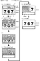
前記示唆演出において、前記可動体を前記第1位置から前記第2位置へ移動させ、可変表示の仮停止態様として前記有利状態に制御されないことを示唆する非有利仮停止態様で可変表示を仮停止したことに基づいて、前記可動体を前記第2位置から前記第1位置へ移動させることが可能であり(例えば、演出制御用CPU120が、ノーマルリーチ演出を開始してから所定期間が経過したタイミングTa3でハズレ組合せの飾り図柄画像009SG020を仮停止表示した後(図8−10(C)参照)、該タイミングTa3から所定期間が経過したタイミングTa4で、可動体32を原点位置から上方へ向けて移動させ(図8−10(D)参照)、ハズレ組合せの飾り図柄画像009SG020を仮停止表示したタイミングTa5から所定期間が経過したタイミングTb1で、可動体32を第1速度(高速)で下降させる制御を開始する部分。)、
前記可動体を前記第2位置から前記第1位置へ移動させるときに、前記非有利仮停止態様を異なる態様へ変化させることが可能である(例えば、演出制御用CPU120が、図8−14(B)(B’)(C)に示すように、可動体32が演出位置から原点位置へ下方に向けて移動(動作)することに連動して飾り図柄画像009SG020の態様を変化させる表示を行う部分。)
ことを特徴としている。
この特徴によれば、可動体を第1位置へ移動させるときに、非有利仮停止態様が異なる態様に変化して有利状態に制御されることを期待できるようになるため、興趣が向上する。
In order to solve the above problems, the gaming machine of
A gaming machine (for example, a pachinko gaming machine 1) that can perform variable display and can be controlled to an advantageous state (for example, a big hit gaming state, a probable variation state, a short time state, etc.),
Display means capable of variable display (for example, the image display device 5);
A movable body (for example, a movable body 32) movable between a first position (for example, an origin position) and a second position (for example, an effect position) different from the first position;
Suggestion effect execution means (for example, a portion where the
With
The suggestion effect execution means includes:
In the suggestion effect, the movable body is moved from the first position to the second position, and the variable display is temporarily stopped in a non-advantageous temporary stop mode that suggests that the variable display temporary stop mode is not controlled to the advantageous state. Based on the above, it is possible to move the movable body from the second position to the first position (for example, the timing Ta3 when a predetermined period has elapsed since the
When the movable body is moved from the second position to the first position, it is possible to change the non-advantageous temporary stop mode to a different mode (for example, the
It is characterized by that.
According to this feature, when the movable body is moved to the first position, the non-advantageous temporary stop mode can be expected to be changed to a different mode and controlled to be in an advantageous state.
本発明の手段2の遊技機は、手段1に記載の遊技機であって、
前記示唆演出実行手段は、前記非有利仮停止態様を変化させたことに基づいて特別演出を実行可能である(例えば、演出制御用CPU120が、可動体32により飾り図柄画像009SG020を完全縮小または完全破壊されたタイミングで、飾り図柄画像009SG020を消去し(図8−14(C)参照)、タイミングTb1から所定期間が経過したタイミングTb2において、可動体32が原点位置に復帰するとともに、背景画像を特殊背景画像009SG012に切り替えた後、さらに復活演出用背景画像009SG013に切り替え(図8−14(D)参照)、復活演出を開始する部分。)
ことを特徴としている。
この特徴によれば、非有利仮停止態様の変化に注目させることができる。
The gaming machine of
The suggestion effect execution means can execute a special effect based on changing the non-advantageous temporary stop mode (for example, the
It is characterized by that.
According to this feature, attention can be paid to changes in the non-advantageous temporary stop mode.
本発明の手段3の遊技機は、手段1または2に記載の遊技機であって、
前記示唆演出実行手段は、前記有利状態に制御する場合、前記有利状態に制御しない場合に前記可動体を前記第2位置から前記第1位置へ移動させるときの動作態様とは異なる動作態様で前記可動体を前記第2位置から前記第1位置へ移動させる(例えば、演出制御用CPU120が、リーチ演出パターン1(ハズレ)の場合は、第1速度よりも遅い第2速度(低速)で可動体32を演出位置から原点位置へ下降させるのに対し、リーチ演出パターン7,8の場合は、第2速度よりも速い第1速度(高速)で可動体32を演出位置から原点位置へ下降させる部分など。)
ことを特徴としている。
この特徴によれば、可動体の動作態様に注目させることができる。
The gaming machine of
The suggestion effect execution means has an operation mode different from an operation mode when moving the movable body from the second position to the first position when controlling to the advantageous state and not controlling to the advantageous state. The movable body is moved from the second position to the first position (for example, when the
It is characterized by that.
According to this feature, attention can be paid to the operation mode of the movable body.
本発明の手段4の遊技機は、手段1〜3のいずれかに記載の遊技機であって、
前記示唆演出実行手段は、
前記可動体を前記第2位置から前記第1位置へ移動させるときに、前記非有利仮停止態様を変化させない第1演出(例えば、リーチ演出パターン2に基づく演出)と前記非有利仮停止態様を変化させる第2演出(例えば、リーチ演出パターン3〜8に基づく演出)とのうちいずれかを実行可能であり、
前記第1演出を実行するときと前記第2演出を実行するときとで、前記可動体を共通の動作態様で前記第2位置から前記第1位置へ移動させる(例えば、可動体32の下降に連動してハズレ組合せの飾り図柄の態様を変化させないリーチ演出パターン2の場合でも、可動体32の下降に連動してハズレ組合せの飾り図柄の態様を変化させるリーチ演出パターン3〜8の場合でも、可動体32の下降速度を同じ高速とする(下降動作態様を共通とする)ことで、下降速度により復活演出が実行されるか否かを予測できないようにしている部分。)
ことを特徴としている。
この特徴によれば、非有利仮停止態様を変化させないときでも、遊技者に非有利仮停止態様が変化することを期待させることができる。
A gaming machine according to
The suggestion effect execution means includes:
When moving the movable body from the second position to the first position, the first effect (for example, the effect based on the reach effect pattern 2) that does not change the non-advantageous temporary stop mode and the non-advantageous temporary stop mode. One of the second effects to be changed (for example, effects based on
When the first effect is executed and when the second effect is executed, the movable body is moved from the second position to the first position in a common operation mode (for example, when the
It is characterized by that.
According to this feature, even when the non-advantageous temporary stop mode is not changed, the player can be expected to change the non-advantageous temporary stop mode.
本発明の手段5の遊技機は、手段1〜4のいずれかに記載の遊技機であって、
前記示唆演出実行手段は、前記可動体の移動に連係して前記非有利仮停止態様を異なる態様へ変化させることが可能である(例えば、演出制御用CPU120が、可動体32が演出位置から原点位置へ下方に向けて移動(動作)することに連動して、ハズレ組合せの飾り図柄画像009SG020の態様を変化させる表示を行う部分。)
ことを特徴としている。
この特徴によれば、可動体の移動に連係して非有利仮停止態様が変化するため、非有利仮停止態様の変化タイミングを遊技者が認識しやすくなる。
A gaming machine of
The suggestion effect execution means can change the non-advantageous temporary stop mode to a different mode in conjunction with the movement of the movable body (for example, the CPU for
It is characterized by that.
According to this feature, since the non-advantageous temporary stop mode changes in conjunction with the movement of the movable body, the player can easily recognize the change timing of the non-advantageous temporary stop mode.
本発明の手段6の遊技機は、手段1〜5のいずれかに記載の遊技機であって、
前記示唆演出実行手段は、
複数種類の変化態様のうちからいずれかの変化態様にて前記非有利仮停止態様を変化させることが可能であり(例えば、演出制御用CPU120が、スーパーリーチ演出パターン3,5,7の場合、可動体32の下降に連動してハズレ組合せの飾り図柄画像009SG020が破壊されるように表示し、スーパーリーチ演出パターン4,6,8の場合、可動体32の下降に連動してハズレ組合せの飾り図柄画像009SG020が縮小されるように表示する部分。)、
前記非有利仮停止態様の変化態様に応じて前記有利状態に制御される割合が異なる(例えば、リーチ演出パターン9,8,7,6,5,4,3,2,1の順に大当り信頼度が高くなるように設定されているとともに、ハズレ組合せの飾り図柄の変化態様(例えば、半分縮小、完全縮小、半分破壊、完全縮小など)に応じて大当りとなる割合が異なる部分。)
ことを特徴としている。
この特徴によれば、非有利仮停止態様の変化態様に遊技者を注目させることができる。
A gaming machine of
The suggestion effect execution means includes:
It is possible to change the non-advantageous temporary stop mode in any one of a plurality of types of change modes (for example, when the
Depending on the change mode of the non-advantageous temporary stop mode, the ratio controlled to the advantageous state is different (for example, the jackpot reliability in the order of
It is characterized by that.
According to this feature, the player can be focused on the change mode of the non-advantageous temporary stop mode.
尚、本発明は、本発明の請求項に記載された発明特定事項のみを有するものであっても良いし、本発明の請求項に記載された発明特定事項とともに該発明特定事項以外の構成を有するものであっても良い。 In addition, this invention may have only the invention specific matter described in the claim of this invention, and the structure other than this invention specific matter is included with the invention specific matter described in the claim of this invention. You may have.
(基本説明)
まず、パチンコ遊技機1の基本的な構成及び制御(一般的なパチンコ遊技機の構成及び制御でもある。)について説明する。
(Basic explanation)
First, a basic configuration and control of the pachinko gaming machine 1 (which is also a configuration and control of a general pachinko gaming machine) will be described.
(パチンコ遊技機1の構成等)
図1は、パチンコ遊技機1の正面図であり、主要部材の配置レイアウトを示す。パチンコ遊技機(遊技機)1は、大別して、遊技盤面を構成する遊技盤(ゲージ盤)2と、遊技盤2を支持固定する遊技機用枠(台枠)3とから構成されている。遊技盤2には、遊技領域が形成され、この遊技領域には、遊技媒体としての遊技球が、所定の打球発射装置から発射されて打ち込まれる。
(Configuration of pachinko machine 1)
FIG. 1 is a front view of a
遊技盤2の所定位置(図1に示す例では、遊技領域の右側方)には、複数種類の特別識別情報としての特別図柄(特図ともいう)の可変表示(特図ゲームともいう)を行う第1特別図柄表示装置4A及び第2特別図柄表示装置4Bが設けられている。これらは、それぞれ、7セグメントのLEDなどからなる。特別図柄は、「0」〜「9」を示す数字や「−」などの点灯パターンなどにより表される。特別図柄には、LEDを全て消灯したパターンが含まれてもよい。
In a predetermined position of the game board 2 (in the example shown in FIG. 1, to the right of the game area), a variable display (also called a special figure game) of special symbols (also called special figures) as a plurality of types of special identification information is provided. A first special
尚、特別図柄の「可変表示」とは、例えば、複数種類の特別図柄を変動可能に表示することである(後述の他の図柄についても同じ)。変動としては、複数の図柄の更新表示、複数の図柄のスクロール表示、1以上の図柄の変形、1以上の図柄の拡大/縮小などがある。特別図柄や後述の普通図柄の変動では、複数種類の特別図柄又は普通図柄が更新表示される。後述の飾り図柄の変動では、複数種類の飾り図柄がスクロール表示又は更新表示されたり、1以上の飾り図柄が変形や拡大/縮小されたりする。尚、変動には、ある図柄を点滅表示する態様も含まれる。可変表示の最後には、表示結果として所定の特別図柄が停止表示(導出又は導出表示などともいう)される(後述の他の図柄の可変表示についても同じ)。尚、可変表示を変動表示、変動と表現する場合がある。 The “variable display” of the special symbol is, for example, to display a plurality of special symbols in a variable manner (the same applies to other symbols described later). Examples of the fluctuation include an update display of a plurality of symbols, a scroll display of a plurality of symbols, deformation of one or more symbols, and enlargement / reduction of one or more symbols. In the case of a special symbol or a variation of a normal symbol described later, a plurality of types of special symbols or normal symbols are updated and displayed. In the variation of the decorative pattern described later, a plurality of types of decorative patterns are scroll-displayed or updated, or one or more decorative symbols are deformed or enlarged / reduced. Note that the variation includes a mode in which a certain symbol is blinked. At the end of the variable display, a predetermined special symbol is stopped as a display result (also referred to as derivation or derivation display) (the same applies to variable display of other symbols described later). Note that variable display may be expressed as variable display or fluctuation.
尚、第1特別図柄表示装置4Aにおいて可変表示される特別図柄を「第1特図」ともいい、第2特別図柄表示装置4Bにおいて可変表示される特別図柄を「第2特図」ともいう。また、第1特図を用いた特図ゲームを「第1特図ゲーム」といい、第2特図を用いた特図ゲームを「第2特図ゲーム」ともいう。尚、特別図柄の可変表示を行う特別図柄表示装置は1種類であってもよい。
The special symbol variably displayed on the first special
遊技盤2における遊技領域の中央付近には画像表示装置5が設けられている。画像表示装置5は、例えばLCD(液晶表示装置)や有機EL(Electro Luminescence)等から構成され、各種の演出画像を表示する。画像表示装置5は、プロジェクタ及びスクリーンから構成されていてもよい。画像表示装置5には、各種の演出画像が表示される。
An
例えば、画像表示装置5の画面上では、第1特図ゲームや第2特図ゲームと同期して、特別図柄とは異なる複数種類の装飾識別情報としての飾り図柄(数字などを示す図柄など)の可変表示が行われる。ここでは、第1特図ゲーム又は第2特図ゲームに同期して、「左」、「中」、「右」の各飾り図柄表示エリア5L、5C、5Rにおいて飾り図柄が可変表示(例えば上下方向のスクロール表示や更新表示)される。尚、同期して実行される特図ゲーム及び飾り図柄の可変表示を総称して単に可変表示ともいう。
For example, on the screen of the
画像表示装置5の画面上には、実行が保留されている可変表示に対応する保留表示や、実行中の可変表示に対応するアクティブ表示を表示するための表示エリアが設けられていてもよい。保留表示及びアクティブ表示を総称して可変表示に対応する可変表示対応表示ともいう。
On the screen of the
保留されている可変表示の数は保留記憶数ともいう。第1特図ゲームに対応する保留記憶数を第1保留記憶数、第2特図ゲームに対応する保留記憶数を第2保留記憶数ともいう。また、第1保留記憶数と第2保留記憶数との合計を合計保留記憶数ともいう。 The number of variable displays that are held is also called the number of stored memories. The number of reserved memories corresponding to the first special figure game is also referred to as a first reserved memory number, and the number of reserved memories corresponding to the second special figure game is also referred to as a second reserved memory number. The total of the first reserved memory number and the second reserved memory number is also referred to as the total reserved memory number.
また、遊技盤2の所定位置には、複数のLEDを含んで構成された第1保留表示器25Aと第2保留表示器25Bとが設けられ、第1保留表示器25Aは、LEDの点灯個数によって、第1保留記憶数を表示し、第2保留表示器25Bは、LEDの点灯個数によって、第2保留記憶数を表示する。
In addition, a
画像表示装置5の下方には、入賞球装置6Aと、可変入賞球装置6Bとが設けられている。
Below the
入賞球装置6Aは、例えば所定の玉受部材によって常に遊技球が進入可能な一定の開放状態に保たれる第1始動入賞口を形成する。第1始動入賞口に遊技球が進入したときには、所定個(例えば3個)の賞球が払い出されるとともに、第1特図ゲームが開始され得る。
The winning
可変入賞球装置6B(普通電動役物)は、ソレノイド81(図2参照)によって閉鎖状態と開放状態とに変化する第2始動入賞口を形成する。可変入賞球装置6Bは、例えば、一対の可動翼片を有する電動チューリップ型役物を備え、ソレノイド81がオフ状態であるときに可動翼片が垂直位置となることにより、当該可動翼片の先端が入賞球装置6Aに近接し、第2始動入賞口に遊技球が進入しない閉鎖状態になる(第2始動入賞口が閉鎖状態になるともいう。)。その一方で、可変入賞球装置6Bは、ソレノイド81がオン状態であるときに可動翼片が傾動位置となることにより、第2始動入賞口に遊技球が進入できる開放状態になる(第2始動入賞口が開放状態になるともいう。)。第2始動入賞口に遊技球が進入したときには、所定個(例えば3個)の賞球が払い出されるとともに、第2特図ゲームが開始され得る。尚、可変入賞球装置6Bは、閉鎖状態と開放状態とに変化するものであればよく、電動チューリップ型役物を備えるものに限定されない。
The variable winning
遊技盤2の所定位置(図1に示す例では、遊技領域の左右下方4箇所)には、所定の玉受部材によって常に一定の開放状態に保たれる一般入賞口10が設けられる。この場合には、一般入賞口10のいずれかに進入したときには、所定個数(例えば10個)の遊技球が賞球として払い出される。
At a predetermined position of the game board 2 (in the example shown in FIG. 1, four places in the lower left and right sides of the game area), there are provided general winning holes 10 that are always kept in a certain open state by a predetermined ball receiving member. In this case, when entering any of the general winning
入賞球装置6Aと可変入賞球装置6Bの下方には、大入賞口を有する特別可変入賞球装置7が設けられている。特別可変入賞球装置7は、ソレノイド82(図2参照)によって開閉駆動される大入賞口扉を備え、その大入賞口扉によって開放状態と閉鎖状態とに変化する特定領域としての大入賞口を形成する。
Below the winning
一例として、特別可変入賞球装置7では、大入賞口扉用(特別電動役物用)のソレノイド82がオフ状態であるときに大入賞口扉が大入賞口を閉鎖状態として、遊技球が大入賞口に進入(通過)できなくなる。その一方で、特別可変入賞球装置7では、大入賞口扉用のソレノイド82がオン状態であるときに大入賞口扉が大入賞口を開放状態として、遊技球が大入賞口に進入しやすくなる。
As an example, in the special variable winning
大入賞口に遊技球が進入したときには、所定個数(例えば14個)の遊技球が賞球として払い出される。大入賞口に遊技球が進入したときには、例えば第1始動入賞口や第2始動入賞口及び一般入賞口10に遊技球が進入したときよりも多くの賞球が払い出される。
When game balls enter the big prize opening, a predetermined number (for example, 14) of game balls are paid out as prize balls. When game balls enter the big prize opening, for example, more prize balls are paid out than when game balls enter the first start prize opening, the second start prize opening, and the
一般入賞口10を含む各入賞口に遊技球が進入することを「入賞」ともいう。特に、始動口(第1始動入賞口、第2始動入賞口始動口)への入賞を始動入賞ともいう。
The entry of a game ball into each winning opening including the general winning
遊技盤2の所定位置(図1に示す例では、遊技領域の左側方)には、普通図柄表示器20が設けられている。一例として、普通図柄表示器20は、7セグメントのLEDなどからなり、特別図柄とは異なる複数種類の普通識別情報としての普通図柄の可変表示を行う。普通図柄は、「0」〜「9」を示す数字や「−」などの点灯パターンなどにより表される。普通図柄には、LEDを全て消灯したパターンが含まれてもよい。このような普通図柄の可変表示は、普図ゲームともいう。
A
画像表示装置5の左方には、遊技球が通過可能な通過ゲート41が設けられている。遊技球が通過ゲート41を通過したことに基づき、普図ゲームが実行される。
On the left side of the
普通図柄表示器20の上方には、普図保留表示器25Cが設けられている。普図保留表示器25Cは、例えば4個のLEDを含んで構成され、実行が保留されている普図ゲームの数である普図保留記憶数をLEDの点灯個数により表示する。
Above the
遊技盤2の表面には、上記の構成以外にも、遊技球の流下方向や速度を変化させる風車及び多数の障害釘が設けられている。遊技領域の最下方には、いずれの入賞口にも進入しなかった遊技球が取り込まれるアウト口が設けられている。
In addition to the above-described configuration, the surface of the
遊技機用枠3の左右上部位置には、効果音等を再生出力するためのスピーカ8L、8Rが設けられており、さらに遊技領域周辺部には、遊技効果用の遊技効果ランプ9が設けられている。遊技効果ランプ9は、LEDを含んで構成されている。
遊技盤2の所定位置(図1では図示略)には、演出に応じて動作する可動体32が設けられている。
At a predetermined position (not shown in FIG. 1) of the
遊技機用枠3の右下部位置には、遊技球を打球発射装置により遊技領域に向けて発射するために遊技者等によって操作される打球操作ハンドル(操作ノブ)30が設けられている。
At the lower right position of the
遊技領域の下方における遊技機用枠3の所定位置には、賞球として払い出された遊技球や所定の球貸機により貸し出された遊技球を、打球発射装置へと供給可能に保持(貯留)する打球供給皿(上皿)が設けられている。上皿の下方には、上皿満タン時に賞球が払い出される打球供給皿(下皿)が設けられている。
At a predetermined position of the
遊技領域の下方における遊技機用枠3の所定位置には、遊技者が把持して傾倒操作が可能なスティックコントローラ31Aが取付けられている。スティックコントローラ31Aには、遊技者が押下操作可能なトリガボタンが設けられている。スティックコントローラ31Aに対する操作は、コントローラセンサユニット35A(図2参照)により検出される。
At a predetermined position of the
遊技領域の下方における遊技機用枠3の所定位置には、遊技者が押下操作などにより所定の指示操作を可能なプッシュボタン31Bが設けられている。プッシュボタン31Bに対する操作は、プッシュセンサ35B(図2参照)により検出される。
At a predetermined position of the
パチンコ遊技機1では、遊技者の動作(操作等)を検出する検出手段として、スティックコントローラ31Aやプッシュボタン31Bが設けられるが、これら以外の検出手段が設けられていてもよい。
In the
(遊技の進行の概略)
パチンコ遊技機1が備える打球操作ハンドル30への遊技者による回転操作により、遊技球が遊技領域に向けて発射される。遊技球が通過ゲート41を通過すると、普通図柄表示器20による普図ゲームが開始される。尚、前回の普図ゲームの実行中の期間等に遊技球が通過ゲート41を通過した場合(遊技球が通過ゲート41を通過したが当該通過に基づく普図ゲームを直ちに実行できない場合)には、当該通過に基づく普図ゲームは所定の上限数(例えば4)まで保留される。
(Outline of game progress)
A game ball is launched toward the game area by a rotation operation by the player to the hitting operation handle 30 provided in the
この普図ゲームでは、特定の普通図柄(普図当り図柄)が停止表示されれば、普通図柄の表示結果が「普図当り」となる。その一方、確定普通図柄として、普図当り図柄以外の普通図柄(普図ハズレ図柄)が停止表示されれば、普通図柄の表示結果が「普図ハズレ」となる。「普図当り」となると、可変入賞球装置6Bを所定期間開放状態とする開放制御が行われる(第2始動入賞口が開放状態になる)。
In this ordinary game, if a specific ordinary symbol (a symbol per ordinary symbol) is stopped and displayed, the display result of the ordinary symbol becomes “per ordinary symbol”. On the other hand, if a normal symbol other than the symbols per ordinary symbol (ordinary symbol losing symbol) is stopped and displayed as the fixed ordinary symbol, the display result of the ordinary symbol becomes “ordinary symbol losing”. When the “normal hit” is reached, an opening control is performed to open the variable winning
入賞球装置6Aに形成された第1始動入賞口に遊技球が進入すると、第1特別図柄表示装置4Aによる第1特図ゲームが開始される。
When a game ball enters the first start winning opening formed in the winning
可変入賞球装置6Bに形成された第2始動入賞口に遊技球が進入すると、第2特別図柄表示装置4Bによる第2特図ゲームが開始される。
When the game ball enters the second start winning opening formed in the variable winning
尚、特図ゲームの実行中の期間や、後述する大当り遊技状態や小当り遊技状態に制御されている期間に、遊技球が始動入賞口へ進入(入賞)した場合(始動入賞が発生したが当該始動入賞に基づく特図ゲームを直ちに実行できない場合)には、当該進入に基づく特図ゲームは所定の上限数(例えば4)までその実行が保留される。 If a game ball enters (wins) a start winning opening during a period during which a special figure game is being executed, or a period where a big hit gaming state or a small hit gaming state, which will be described later, is controlled (a start winning has occurred) In the case where the special game based on the start prize cannot be immediately executed), the special game based on the entry is suspended until a predetermined upper limit number (for example, 4).
特図ゲームにおいて、確定特別図柄として特定の特別図柄(大当り図柄、例えば「7」、後述の大当り種別に応じて実際の図柄は異なる。)が停止表示されれば、「大当り」となり、大当り図柄とは異なる所定の特別図柄(小当り図柄、例えば「2」)が停止表示されれば、「小当り」となる。また、大当り図柄や小当り図柄とは異なる特別図柄(ハズレ図柄、例えば「−」)が停止表示されれば「ハズレ」となる。 In a special game, if a specific special symbol (a jackpot symbol, for example, “7”, the actual symbol differs depending on the jackpot type to be described later) is stopped and displayed as a special symbol, it will be a “hit” symbol. If a predetermined special symbol different from (a small hit symbol, for example, “2”) is stopped and displayed, “small hit” is obtained. In addition, if a special symbol (losing symbol, for example, “-”) different from the big hit symbol or the small winning symbol is stopped and displayed, it is “lost”.
特図ゲームでの表示結果が「大当り」になった後には、遊技者にとって有利な有利状態として大当り遊技状態に制御される。特図ゲームでの表示結果が「小当り」になった後には、小当り遊技状態に制御される。 After the display result in the special figure game becomes “big hit”, the big hit gaming state is controlled as an advantageous state advantageous to the player. After the display result in the special figure game becomes “small hit”, the game is controlled to the small hit gaming state.
大当り遊技状態においては、遊技者は、遊技球を大入賞口に進入させることで、賞球を得ることができる。従って、大当り遊技状態は、遊技者にとって有利な状態である。大当り遊技状態におけるラウンド数が多い程、また、開放上限期間が長い程遊技者にとって有利となる。 In the big hit game state, the player can obtain a prize ball by causing the game ball to enter the big prize opening. Therefore, the big hit gaming state is an advantageous state for the player. The greater the number of rounds in the big hit gaming state, and the longer the opening upper limit period, the more advantageous for the player.
尚、「大当り」には、大当り種別が設定されている。例えば、大入賞口の開放態様(ラウンド数や開放上限期間)や、大当り遊技状態後の遊技状態(後述の、通常状態、時短状態、確変状態など)を複数種類用意し、これらに応じて大当り種別が設定されている。大当り種別として、多くの賞球を得ることができる大当り種別や、賞球の少ない又はほとんど賞球を得ることができない大当り種別が設けられていてもよい。 Note that a “big hit” type is set for the big hit. For example, a number of types of opening of the big prize opening (number of rounds and opening upper limit period) and gaming state after the big hit gaming state (described later, normal state, short-time state, probability change state, etc.) are prepared, and depending on them Type is set. As the jackpot type, there may be provided a jackpot type that can obtain many prize balls, or a jackpot type that has few prize balls or hardly obtains prize balls.
小当り遊技状態では、特別可変入賞球装置7により形成される大入賞口が所定の開放態様で開放状態となる。例えば、小当り遊技状態では、一部の大当り種別のときの大当り遊技状態と同様の開放態様(大入賞口の開放回数が上記ラウンド数と同じであり、かつ、大入賞口の閉鎖タイミングも同じ等)で大入賞口が開放状態となる。尚、大当り種別と同様に、「小当り」にも小当り種別を設けてもよい。
In the small hit gaming state, the special winning opening formed by the special variable winning
大当り遊技状態が終了した後は、上記大当り種別に応じて、時短状態や確変状態に制御されることがある。 After the big hit gaming state is ended, depending on the big hit type, it may be controlled to a short time state or a probable change state.
時短状態では、平均的な特図変動時間(特図を変動させる期間)を通常状態よりも短縮させる制御(時短制御)が実行される。時短状態では、平均的な普図変動時間(普図を変動させる期間)を通常状態よりも短縮させたり、普図ゲームで「普図当り」となる確率を通常状態よりも向上させる等により、第2始動入賞口に遊技球が進入しやすくなる制御(高開放制御、高ベース制御)も実行される。時短状態は、特別図柄(特に第2特別図柄)の変動効率が向上する状態であるので、遊技者にとって有利な状態である。 In the short-time state, control (short-time control) is executed to shorten the average special figure change time (period during which the special figure is changed) compared to the normal state. In the short-time state, by reducing the average normal map change time (period in which the normal map is changed) from the normal state, or by improving the probability of “per normal map” in the normal game, than the normal state, Control (high opening control, high base control) that makes it easy for the game ball to enter the second start winning opening is also executed. The short-time state is a state advantageous for the player because the variation efficiency of the special symbol (especially the second special symbol) is improved.
確変状態(確率変動状態)では、時短制御に加えて、表示結果が「大当り」となる確率が通常状態よりも高くなる確変制御が実行される。確変状態は、特別図柄の変動効率が向上することに加えて「大当り」となりやすい状態であるので、遊技者にとってさらに有利な状態である。 In the probability variation state (probability variation state), in addition to the time reduction control, probability variation control is executed in which the probability that the display result is “big hit” is higher than in the normal state. The probability variation state is a state that is more advantageous for the player because it is likely to be a “hit” in addition to the improvement of the variation efficiency of the special symbol.
時短状態や確変状態は、所定回数の特図ゲームが実行されたことと、次回の大当り遊技状態が開始されたこと等といった、いずれか1つの終了条件が先に成立するまで継続する。所定回数の特図ゲームが実行されたことが終了条件となるものを、回数切り(回数切り時短、回数切り確変等)ともいう。 The short-time state or the probability change state continues until any one end condition such as that a predetermined number of special game has been executed and the next big hit game state has been established. A game whose end condition is that a predetermined number of special game has been executed is also referred to as a number of cuts (short time cut, number change probability change, etc.).
通常状態とは、遊技者にとって有利な大当り遊技状態等の有利状態、時短状態、確変状態等の特別状態以外の遊技状態のことであり、普図ゲームにおける表示結果が「普図当り」となる確率及び特図ゲームにおける表示結果が「大当り」となる確率などのパチンコ遊技機1が、パチンコ遊技機1の初期設定状態(例えばシステムリセットが行われた場合のように、電源投入後に所定の復帰処理を実行しなかったとき)と同一に制御される状態である。
The normal state is a gaming state other than a special state such as a big hit gaming state advantageous for the player, a short-time state, a probable change state, etc., and the display result in the ordinary game is “per ordinary figure”. The
確変制御が実行されている状態を高確状態、確変制御が実行されていない状態を低確状態ともいう。時短制御が実行されている状態を高ベース状態、時短制御が実行されていない状態を低ベース状態ともいう。これらを組合せて、時短状態は低確高ベース状態、確変状態は高確高ベース状態、通常状態は低確低ベース状態などともいわれる。高確状態かつ低ベース状態は高確低ベース状態ともいう。 A state in which the probability variation control is being executed is also referred to as a high probability state, and a state in which the probability variation control is not being performed is also referred to as a low probability state. The state where the time reduction control is executed is also referred to as a high base state, and the state where the time reduction control is not executed is also referred to as a low base state. By combining these, it is also said that the time-short state is a low-accuracy base state, the probability variation state is a high-accuracy high-base state, the normal state is a low-accuracy low-base state, and the like. The highly accurate state and the low base state are also referred to as a highly accurate low base state.
小当り遊技状態が終了した後は、遊技状態の変更が行われず、特図ゲームの表示結果が「小当り」となる以前の遊技状態に継続して制御される(但し、「小当り」発生時の特図ゲームが、上記回数切りにおける上記所定回数目の特図ゲームである場合には、当然遊技状態が変更される)。尚、特図ゲームの表示結果として「小当り」がなくてもよい。 After the small hit game state ends, the game state is not changed, and the game state before the display result of the special game is “small hit” is controlled continuously (however, “small hit” occurs) If the special figure game at the time is the special figure game of the predetermined number of times, the gaming state is naturally changed). It should be noted that there is no “small hit” as the display result of the special game.
尚、遊技状態は、大当り遊技状態中に遊技球が特定領域(例えば、大入賞口内の特定領域)を通過したことに基づいて、変化してもよい。例えば、遊技球が特定領域を通過したとき、その大当り遊技状態後に確変状態に制御してもよい。 Note that the gaming state may change based on the fact that the game ball has passed a specific area (for example, a specific area in the big prize opening) during the big hit gaming state. For example, when the game ball passes through a specific area, the game ball may be controlled to be in a probable change state after the big hit game state.
(演出の進行など)
パチンコ遊技機1では、遊技の進行に応じて種々の演出(遊技の進行状況を報知したり、遊技を盛り上げたりする演出)が実行される。当該演出について以下説明する。尚、当該演出は、画像表示装置5に各種の演出画像を表示することによって行われるが、当該表示に加えて又は代えて、スピーカ8L、8Rからの音声出力、及び/又は、遊技効果ランプ9の点等/消灯、可動体32の動作等により行われてもよい。
(Progress of production, etc.)
In the
遊技の進行に応じて実行される演出として、画像表示装置5に設けられた「左」、「中」、「右」の飾り図柄表示エリア5L、5C、5Rでは、第1特図ゲーム又は第2特図ゲームが開始されることに対応して、飾り図柄の可変表示が開始される。第1特図ゲームや第2特図ゲームにおいて表示結果(確定特別図柄ともいう。)が停止表示されるタイミングでは、飾り図柄の可変表示の表示結果となる確定飾り図柄(3つの飾り図柄の組合せ)も停止表示(導出)される。
In the “left”, “middle”, and “right” decorative
飾り図柄の可変表示が開始されてから終了するまでの期間では、飾り図柄の可変表示の態様が所定のリーチ態様となる(リーチが成立する)ことがある。ここで、リーチ態様とは、画像表示装置5の画面上にて停止表示された飾り図柄が後述の大当り組合せの一部を構成しているときに未だ停止表示されていない飾り図柄については可変表示が継続している態様などのことである。
In the period from the start of the variable display of the decorative design to the end thereof, the variable display mode of the decorative design may be a predetermined reach mode (reach is established). Here, the reach mode is a variable display for decorative symbols that have not been stopped yet when the decorative symbols stopped on the screen of the
また、飾り図柄の可変表示中に上記リーチ態様となったことに対応してリーチ演出が実行される。パチンコ遊技機1では、演出態様に応じて表示結果(特図ゲームの表示結果や飾り図柄の可変表示の表示結果)が「大当り」となる割合(大当り信頼度、大当り期待度とも呼ばれる。)が異なる複数種類のリーチ演出が実行される。リーチ演出には、例えば、ノーマルリーチと、ノーマルリーチよりも大当り信頼度の高いスーパーリーチと、がある。
In addition, a reach effect is executed in response to the above-described reach mode during variable display of decorative symbols. In the
特図ゲームの表示結果が「大当り」となるときには、画像表示装置5の画面上において、飾り図柄の可変表示の表示結果として、予め定められた大当り組合せとなる確定飾り図柄が導出される(飾り図柄の可変表示の表示結果が「大当り」となる)。一例として、「左」、「中」、「右」の飾り図柄表示エリア5L、5C、5Rにおける所定の有効ライン上に同一の飾り図柄(例えば、「7」等)が揃って停止表示される。
When the display result of the special figure game is “big hit”, a predetermined decorative pattern that is a predetermined big hit combination is derived as a display result of variable display of decorative symbols on the screen of the image display device 5 (decoration) The display result of the variable display of the symbol is “big hit”). As an example, the same decorative symbols (for example, “7”, etc.) are stopped and displayed together on predetermined active lines in the “left”, “middle”, and “right” decorative
大当り遊技状態の終了後に確変状態に制御される「確変大当り」である場合には、奇数の飾り図柄(例えば、「7」等)が揃って停止表示され、大当り遊技状態の終了後に確変状態に制御されない「非確変大当り(通常大当り)」である場合には、偶数の飾り図柄(例えば、「6」等)が揃って停止表示されるようにしてもよい。この場合、奇数の飾り図柄を確変図柄、偶数の飾り図柄を非確変図柄(通常図柄)ともいう。非確変図柄でリーチ態様となった後に、最終的に「確変大当り」となる昇格演出を実行するようにしてもよい。 In the case of “probable big hit”, which is controlled to the probable change state after the big hit gaming state, odd numbers of decorative symbols (for example, “7”, etc.) are all stopped and displayed, and after the big hit gaming state is finished, In the case of a “non-probable big hit (normal big hit)” that is not controlled, an even number of decorative symbols (for example, “6”, etc.) may be stopped and displayed together. In this case, odd-numbered decorative symbols are also referred to as probability variation symbols, and even-numbered decorative symbols are also referred to as non-probable variation symbols (normal symbols). After becoming a reach mode with a non-probable variation pattern, a promotion effect that finally becomes a “probability large hit” may be executed.
特図ゲームの表示結果が「小当り」となるときには、画像表示装置5の画面上において、飾り図柄の可変表示の表示結果として、予め定められた小当り組合せとなる確定飾り図柄(例えば、「1 3 5」等)が導出される(飾り図柄の可変表示の表示結果が「小当り」となる)。一例として、「左」、「中」、「右」の飾り図柄表示エリア5L、5C、5Rにおける所定の有効ライン上にチャンス目を構成する飾り図柄が停止表示される。尚、特図ゲームの表示結果が、一部の大当り種別(小当り遊技状態と同様の態様の大当り遊技状態の大当り種別)の「大当り」となるときと、「小当り」となるときとで、共通の確定飾り図柄が導出表示されてもよい。
When the display result of the special game is “small hit”, as a display result of variable display of decorative symbols on the screen of the
特図ゲームの表示結果が「ハズレ」となる場合には、飾り図柄の可変表示の態様がリーチ態様とならずに、飾り図柄の可変表示の表示結果として、非リーチ組合せの確定飾り図柄(「非リーチハズレ」ともいう。)が停止表示される(飾り図柄の可変表示の表示結果が「非リーチハズレ」となる)ことがある。また、表示結果が「ハズレ」となる場合には、飾り図柄の可変表示の態様がリーチ態様となった後に、飾り図柄の可変表示の表示結果として、大当り組合せでない所定のリーチ組合せ(「リーチハズレ」ともいう)の確定飾り図柄が停止表示される(飾り図柄の可変表示の表示結果が「リーチハズレ」となる)こともある。 When the display result of the special figure game is “losing”, the decorative display variable display mode is not the reach mode, but the non-reach combination fixed display pattern (“ (Also referred to as “non-reach lose”) may be stopped (the display result of the variable display of the decorative pattern may be “non-reach lose”). Further, when the display result is “losing”, after the decorative display variable display mode becomes the reach mode, the predetermined reach combination (“reach loss”) that is not a big hit combination is displayed as the variable display display result of the decorative design. In other cases, the fixed decorative symbol (also referred to as “definitely”) is stopped and displayed (the display result of the variable display of the decorative symbol is “reach lose”).
パチンコ遊技機1が実行可能な演出には、上記の可変表示対応表示(保留表示やアクティブ表示)を表示することも含まれる。また、他の演出として、例えば、大当り信頼度を予告する予告演出等が飾り図柄の可変表示中に実行される。予告演出には、実行中の可変表示における大当り信頼度を予告する予告演出や、実行前の可変表示(実行が保留されている可変表示)における大当り信頼度を予告する先読み予告演出がある。先読み予告演出として、可変表示対応表示(保留表示やアクティブ表示)の表示態様を通常とは異なる態様に変化させる演出が実行されるようにしてもよい。
The effects that can be executed by the
また、画像表示装置5において、飾り図柄の可変表示中に飾り図柄を一旦仮停止させた後に可変表示を再開させることで、1回の可変表示を擬似的に複数回の可変表示のように見せる擬似連演出を実行するようにしてもよい。
Further, in the
大当り遊技状態中にも、大当り遊技状態を報知する大当り中演出が実行される。大当り中演出としては、ラウンド数を報知する演出や、大当り遊技状態の価値が向上することを示す昇格演出が実行されてもよい。また、小当り遊技状態中にも、小当り遊技状態を報知する小当り中演出が実行される。尚、小当り遊技状態中と、一部の大当り種別(小当り遊技状態と同様の態様の大当り遊技状態の大当り種別で、例えばその後の遊技状態を高確状態とする大当り種別)での大当り遊技状態とで、共通の演出を実行することで、現在が小当り遊技状態中であるか、大当り遊技状態中であるかを遊技者に分からないようにしてもよい。そのような場合であれば、小当り遊技状態の終了後と大当り遊技状態の終了後とで共通の演出を実行することで、高確状態であるか低確状態であるかを識別できないようにしてもよい。 Even during the big hit game state, the big hit effect for informing the big hit game state is executed. As the big hit effect, an effect for notifying the number of rounds or a promotion effect indicating that the value of the big hit gaming state may be executed. In addition, during the small hit game state, the small hit effect during the small hit game state is executed. In addition, the big hit game in the small hit game state and a part of the big hit type (a big hit type of the big hit game state in the same manner as the small hit game state, for example, a big hit type in which the subsequent game state is a high probability state) By executing a common effect with the state, the player may not know whether the current state is the small hit game state or the big hit game state. In such a case, a common effect is executed after the end of the small hit gaming state and after the end of the big hit gaming state, so that it is not possible to identify whether the state is a high probability state or a low probability state. May be.
また、例えば特図ゲーム等が実行されていないときには、画像表示装置5にデモ(デモンストレーション)画像が表示される(客待ちデモ演出が実行される)。 Further, for example, when a special game or the like is not being executed, a demonstration (demonstration) image is displayed on the image display device 5 (a customer waiting demonstration effect is executed).
(基板構成)
パチンコ遊技機1には、例えば図2に示すような主基板11、演出制御基板12、音声制御基板13、ランプ制御基板14、中継基板15などが搭載されている。その他にも、パチンコ遊技機1の背面には、例えば払出制御基板、情報端子基板、発射制御基板、電源基板などといった、各種の基板が配置されている。
(Board configuration)
In the
主基板11は、メイン側の制御基板であり、パチンコ遊技機1における上記遊技の進行(特図ゲームの実行(保留の管理を含む)、普図ゲームの実行(保留の管理を含む)、大当り遊技状態、小当り遊技状態、遊技状態など)を制御する機能を有する。主基板11は、遊技制御用マイクロコンピュータ100、スイッチ回路110、ソレノイド回路111などを有する。
The
主基板11に搭載された遊技制御用マイクロコンピュータ100は、例えば1チップのマイクロコンピュータであり、ROM(Read Only Memory)101と、RAM(Random Access Memory)102と、CPU(Central Processing Unit)103と、乱数回路104と、I/O(Input/Output port)105とを備える。
The
CPU103は、ROM101に記憶されたプログラムを実行することにより、遊技の進行を制御する処理(主基板11の機能を実現する処理)を行う。このとき、ROM101が記憶する各種データ(後述の変動パターン、後述の演出制御コマンド、後述の各種決定を行う際に参照される各種テーブルなどのデータ)が用いられ、RAM102がメインメモリとして使用される。RAM102は、その一部または全部がパチンコ遊技機1に対する電力供給が停止しても、所定期間記憶内容が保存されるバックアップRAMとなっている。尚、ROM101に記憶されたプログラムの全部又は一部をRAM102に展開して、RAM102上で実行するようにしてもよい。
The
乱数回路104は、遊技の進行を制御するときに使用される各種の乱数値(遊技用乱数)を示す数値データを更新可能にカウントする。遊技用乱数は、CPU103が所定のコンピュータプログラムを実行することで更新されるもの(ソフトウェアで更新されるもの)であってもよい。
The
I/O105は、例えば各種信号(後述の検出信号)が入力される入力ポートと、各種信号(第1特別図柄表示装置4A、第2特別図柄表示装置4B、普通図柄表示器20、第1保留表示器25A、第2保留表示器25B、普図保留表示器25Cなどを制御(駆動)する信号、ソレノイド駆動信号)を伝送するための出力ポートとを含んで構成される。
The I /
スイッチ回路110は、遊技球検出用の各種スイッチ(ゲートスイッチ21、始動口スイッチ(第1始動口スイッチ22Aおよび第2始動口スイッチ22B)、カウントスイッチ23)からの検出信号(遊技球が通過又は進入してスイッチがオンになったことを示す検出信号など)を取り込んで遊技制御用マイクロコンピュータ100に伝送する。検出信号の伝送により、遊技球の通過又は進入が検出されたことになる。
The
ソレノイド回路111は、遊技制御用マイクロコンピュータ100からのソレノイド駆動信号(例えば、ソレノイド81やソレノイド82をオンする信号など)を、普通電動役物用のソレノイド81や大入賞口扉用のソレノイド82に伝送する。
The
主基板11(遊技制御用マイクロコンピュータ100)は、遊技の進行の制御の一部として、遊技の進行に応じて演出制御コマンド(遊技の進行状況等を指定(通知)するコマンド)を演出制御基板12に供給する。主基板11から出力された演出制御コマンドは、中継基板15により中継され、演出制御基板12に供給される。当該演出制御コマンドには、例えば主基板11における各種の決定結果(例えば、特図ゲームの表示結果(大当り種別を含む。)、特図ゲームを実行する際に使用される変動パターン(詳しくは後述))、遊技の状況(例えば、可変表示の開始や終了、大入賞口の開放状況、入賞の発生、保留記憶数、遊技状態)、エラーの発生等を指定するコマンド等が含まれる。
The main board 11 (game control microcomputer 100) sends an effect control command (a command for designating (notifying) the progress of the game) according to the progress of the game as part of the control of the progress of the game. 12 is supplied. The effect control command output from the
演出制御基板12は、主基板11とは独立したサブ側の制御基板であり、演出制御コマンドを受信し、受信した演出制御コマンドに基づいて演出(遊技の進行に応じた種々の演出であり、可動体32の駆動、エラー報知、電断復旧の報知等の各種報知を含む)を実行する機能を有する。
The
演出制御基板12には、演出制御用CPU120と、ROM121と、RAM122と、表示制御部123と、乱数回路124と、I/O125とが搭載されている。
On the
演出制御用CPU120は、ROM121に記憶されたプログラムを実行することにより、表示制御部123とともに演出を実行するための処理(演出制御基板12の上記機能を実現するための処理であり、実行する演出の決定等を含む)を行う。このとき、ROM121が記憶する各種データ(各種テーブルなどのデータ)が用いられ、RAM122がメインメモリとして使用される。
The
演出制御用CPU120は、コントローラセンサユニット35Aやプッシュセンサ35Bからの検出信号(遊技者による操作を検出したときに出力される信号であり、操作内容を適宜示す信号)に基づいて演出の実行を表示制御部123に指示することもある。
The
表示制御部123は、VDP(Video Display Processor)、CGROM(Character Generator ROM)、VRAM(Video RAM)などを備え、演出制御用CPU120からの演出の実行指示に基づき、演出を実行する。
The
表示制御部123は、演出制御用CPU120からの演出の実行指示に基づき、実行する演出に応じた映像信号を画像表示装置5に供給することで、演出画像を画像表示装置5に表示させる。表示制御部123は、さらに、演出画像の表示に同期した音声出力や、遊技効果ランプ9の点灯/消灯を行うため、音指定信号(出力する音声を指定する信号)を音声制御基板13に供給したり、ランプ信号(ランプの点灯/消灯態様を指定する信号)をランプ制御基板14に供給したりする。また、表示制御部123は、可動体32を動作させる信号を当該可動体32又は当該可動体32を駆動する駆動回路に供給する。
The
音声制御基板13は、スピーカ8L、8Rを駆動する各種回路を搭載しており、当該音指定信号に基づきスピーカ8L、8Rを駆動し、当該音指定信号が指定する音声をスピーカ8L、8Rから出力させる。
The
ランプ制御基板14は、遊技効果ランプ9を駆動する各種回路を搭載しており、当該ランプ信号に基づき遊技効果ランプ9を駆動し、当該ランプ信号が指定する態様で遊技効果ランプ9を点灯/消灯する。このようにして、表示制御部123は、音声出力、ランプの点灯/消灯を制御する。
The
尚、音声出力、ランプの点灯/消灯の制御(音指定信号やランプ信号の供給等)、可動体32の制御(可動体32を動作させる信号の供給等)は、演出制御用CPU120が実行するようにしてもよい。
The
乱数回路124は、各種演出を実行するために使用される各種の乱数値(演出用乱数)を示す数値データを更新可能にカウントする。演出用乱数は、演出制御用CPU120が所定のコンピュータプログラムを実行することで更新されるもの(ソフトウェアで更新されるもの)であってもよい。
The
演出制御基板12に搭載されたI/O125は、例えば主基板11などから伝送された演出制御コマンドを取り込むための入力ポートと、各種信号(映像信号、音指定信号、ランプ信号)を伝送するための出力ポートとを含んで構成される。
For example, the I /
演出制御基板12、音声制御基板13、ランプ制御基板14といった、主基板11以外の基板をサブ基板ともいう。パチンコ遊技機1のようにサブ基板が機能別に複数設けられていてもよいし、1のサブ基板が複数の機能を有するように構成してもよい。
A board other than the
(動作)
次に、パチンコ遊技機1の動作(作用)を説明する。
(Operation)
Next, the operation (action) of the
(主基板11の主要な動作)
まず、主基板11における主要な動作を説明する。パチンコ遊技機1に対して電力供給が開始されると、遊技制御用マイクロコンピュータ100が起動し、CPU103によって遊技制御メイン処理が実行される。図3は、主基板11におけるCPU103が実行する遊技制御メイン処理を示すフローチャートである。
(Main operations of the main board 11)
First, main operations in the
図3に示す遊技制御メイン処理では、CPU103は、まず、割込禁止に設定する(ステップS1)。続いて、必要な初期設定を行う(ステップS2)。初期設定には、スタックポインタの設定、内蔵デバイス(CTC(カウンタ/タイマ回路)、パラレル入出力ポート等)のレジスタ設定、RAM102をアクセス可能状態にする設定等が含まれる。
In the game control main process shown in FIG. 3, the
次いで、クリアスイッチからの出力信号がオンであるか否かを判定する(ステップS3)。クリアスイッチは、例えば電源基板に搭載されている。クリアスイッチがオンの状態で電源が投入されると、出力信号(クリア信号)が入力ポートを介して遊技制御用マイクロコンピュータ100に入力される。クリアスイッチからの出力信号がオンである場合、初期化処理(ステップS8)を実行する。初期化処理では、CPU103は、RAM102に記憶されるフラグ、カウンタ、バッファをクリアするRAMクリア処理を行い、作業領域に初期値を設定する。
Next, it is determined whether or not the output signal from the clear switch is on (step S3). The clear switch is mounted on, for example, a power supply board. When the power is turned on while the clear switch is on, an output signal (clear signal) is input to the
また、CPU103は、初期化を指示する演出制御コマンドを演出制御基板12に送信する(ステップS9)。演出制御用CPU120は、当該演出制御コマンドを受信すると、例えば画像表示装置5において、遊技機の制御の初期化がなされたことを報知するための画面表示を行う。
Further, the
クリアスイッチからの出力信号がオンでない場合には、RAM102(バックアップRAM)にバックアップデータが保存されているか否かを判定する(ステップS4)。不測の停電等(電断)によりパチンコ遊技機1への電力供給が停止したときには、CPU103は、当該電力供給の停止によって動作できなくなる直前に、電源供給停止時処理を実行する。この電源供給停止時処理では、RAM102にデータをバックアップすることを示すバックアップフラグをオンする処理、RAM102のデータ保護処理等が実行される。データ保護処理には、誤り検出符号(チェックサム、パリティビット等)の付加、各種データをバックアップする処理が含まれる。バックアップされるデータには、遊技を進行するための各種データ(各種フラグ、各種タイマの状態等を含む)の他、前記バックアップフラグの状態や誤り検出符号も含まれる。ステップS4では、バックアップフラグがオンであるか否かを判定する。バックアップフラグがオフでRAM102にバックアップデータが記憶されていない場合、初期化処理(ステップS8)を実行する。
If the output signal from the clear switch is not on, it is determined whether backup data is stored in the RAM 102 (backup RAM) (step S4). When the power supply to the
RAM102にバックアップデータが記憶されている場合、CPU103は、バックアップしたデータのデータチェックを行い(誤り検出符号を用いて行われる)、データが正常か否かを判定する(ステップS5)。ステップS5では、例えば、パリティビットやチェックサムにより、RAM102のデータが、電力供給停止時のデータと一致するか否かを判定する。これらが一致すると判定された場合、RAM102のデータが正常であると判定する。
When the backup data is stored in the
RAM102のデータが正常でないと判定された場合、内部状態を電力供給停止時の状態に戻すことができないので、初期化処理(ステップS8)を実行する。
If it is determined that the data in the
RAM102のデータが正常であると判定された場合、CPU103は、主基板11の内部状態を電力供給停止時の状態に戻すための復旧処理(ステップS6)を行う。復旧処理では、CPU103は、RAM102の記憶内容(バックアップしたデータの内容)に基づいて作業領域の設定を行う。これにより、電力供給停止時の遊技状態に復旧し、特別図柄の変動中であった場合には、後述の遊技制御用タイマ割込み処理の実行によって、復旧前の状態から特別図柄の変動が再開されることになる。
When it is determined that the data in the
そして、CPU103は、電断からの復旧を指示する演出制御コマンドを演出制御基板12に送信する(ステップS7)。これに合わせて、バックアップされている電断前の遊技状態を指定する演出制御コマンドや、特図ゲームの実行中であった場合には当該実行中の特図ゲームの表示結果を指定する演出制御コマンドを送信するようにしてもよい。これらコマンドは、後述の特別図柄プロセス処理で送信設定されるコマンドと同じコマンドを使用できる。演出制御用CPU120は、電断からの復旧時を特定する演出制御コマンドを受信すると、例えば画像表示装置5において、電断からの復旧がなされたこと又は電断からの復旧中であることを報知するための画面表示を行う。演出制御用CPU120は、前記演出制御コマンドに基づいて、適宜の画面表示を行うようにしてもよい。
And CPU103 transmits the production control command which instruct | indicates the recovery | restoration from a power interruption to the production control board 12 (step S7). In conjunction with this, an effect control command for designating a backed-up gaming state before power interruption, or an effect control for designating the display result of the special figure game being executed when the special figure game is being executed. A command may be transmitted. As these commands, the same commands as those set for transmission in the special symbol process processing described later can be used. When the
復旧処理または初期化処理を終了して演出制御基板12に演出制御コマンドを送信した後には、CPU103は、乱数回路104を初期設定する乱数回路設定処理を実行する(ステップS10)。そして、所定時間(例えば2ms)毎に定期的にタイマ割込がかかるように遊技制御用マイクロコンピュータ100に内蔵されているCTCのレジスタの設定を行い(ステップS11)、割込みを許可する(ステップS12)。その後、ループ処理に入る。以後、所定時間(例えば2ms)ごとにCTCから割込み要求信号がCPU103へ送出され、CPU103は定期的にタイマ割込み処理を実行することができる。
After finishing the restoration process or the initialization process and transmitting the effect control command to the
こうした遊技制御メイン処理を実行したCPU103は、CTCからの割込み要求信号を受信して割込み要求を受付けると、図4のフローチャートに示す遊技制御用タイマ割込み処理を実行する。図4に示す遊技制御用タイマ割込み処理を開始すると、CPU103は、まず、所定のスイッチ処理を実行することにより、スイッチ回路110を介してゲートスイッチ21、第1始動口スイッチ22A、第2始動口スイッチ22B、カウントスイッチ23といった各種スイッチからの検出信号の受信の有無を判定する(ステップS21)。続いて、所定のメイン側エラー処理を実行することにより、パチンコ遊技機1の異常診断を行い、その診断結果に応じて必要ならば警告を発生可能とする(ステップS22)。この後、所定の情報出力処理を実行することにより、例えばパチンコ遊技機1の外部に設置されたホール管理用コンピュータに供給される大当り情報(大当りの発生回数等を示す情報)、始動情報(始動入賞の回数等を示す情報)、確率変動情報(確変状態となった回数等を示す情報)などのデータを出力する(ステップS23)。
When the
情報出力処理に続いて、主基板11の側で用いられる遊技用乱数の少なくとも一部をソフトウェアにより更新するための遊技用乱数更新処理を実行する(ステップS24)。この後、CPU103は、特別図柄プロセス処理を実行する(ステップS25)。CPU103がタイマ割込み毎に特別図柄プロセス処理を実行することにより、特図ゲームの実行及び保留の管理や、大当り遊技状態や小当り遊技状態の制御、遊技状態の制御などが実現される(詳しくは後述)。
Subsequent to the information output process, a game random number update process for updating at least a part of the game random numbers used on the
特別図柄プロセス処理に続いて、普通図柄プロセス処理が実行される(ステップS26)。CPU103がタイマ割込み毎に普通図柄プロセス処理を実行することにより、ゲートスイッチ21からの検出信号に基づく(通過ゲート41に遊技球が通過したことに基づく)普図ゲームの実行及び保留の管理や、「普図当り」に基づく可変入賞球装置6Bの開放制御などを可能にする。普図ゲームの実行は、普通図柄表示器20を駆動することにより行われ、普図保留表示器25Cを点灯させることにより普図保留数を表示する。
Following the special symbol process, the normal symbol process is executed (step S26). The
普通図柄プロセス処理を実行した後、遊技制御用タイマ割込み処理の一部として、電断が発生したときの処理、賞球を払い出すための処理等などが行われてもよい。その後、CPU103は、コマンド制御処理を実行する(ステップS27)。CPU103は、上記各処理にて演出制御コマンドを送信設定することがある。ステップS27のコマンド制御処理では、送信設定された演出制御コマンドを演出制御基板12などのサブ側の制御基板に対して伝送させる処理が行われる。コマンド制御処理を実行した後には、割込みを許可してから、遊技制御用タイマ割込み処理を終了する。
After executing the normal symbol process, a process when a power interruption occurs, a process for paying out a prize ball, or the like may be performed as part of the game control timer interrupt process. Thereafter, the
図5は、特別図柄プロセス処理として、図4に示すステップS25にて実行される処理の一例を示すフローチャートである。この特別図柄プロセス処理において、CPU103は、まず、始動入賞判定処理を実行する(ステップS101)。
FIG. 5 is a flowchart showing an example of processing executed in step S25 shown in FIG. 4 as special symbol process processing. In this special symbol process, the
始動入賞判定処理では、始動入賞の発生を検出し、RAM102の所定領域に保留情報を格納し保留記憶数を更新する処理が実行される。始動入賞が発生すると、表示結果(大当り種別を含む)や変動パターンを決定するための乱数値が抽出され、保留情報として記憶される。また、抽出した乱数値に基づいて、表示結果や変動パターンを先読み判定する処理が実行されてもよい。保留情報や保留記憶数を記憶した後には、演出制御基板12に始動入賞の発生、保留記憶数、先読み判定等の判定結果を指定するための演出制御コマンドを送信するための送信設定が行われる。こうして送信設定された始動入賞時の演出制御コマンドは、例えば特別図柄プロセス処理が終了した後、図4に示すステップS27のコマンド制御処理が実行されることなどにより、主基板11から演出制御基板12に対して伝送される。
In the start winning determination process, a process of detecting occurrence of a start winning, storing hold information in a predetermined area of the
S101にて始動入賞判定処理を実行した後、CPU103は、RAM102に設けられた特図プロセスフラグの値に応じて、ステップS110〜S120の処理のいずれかを選択して実行する。尚、特別図柄プロセス処理の各処理(ステップS110〜S120)では、各処理に対応した演出制御コマンドを演出制御基板12に送信するための送信設定が行われる。
After executing the start winning determination process in S101, the
ステップS110の特別図柄通常処理は、特図プロセスフラグの値が“0”(初期値)のときに実行される。この特別図柄通常処理では、保留情報の有無などに基づいて、第1特図ゲーム又は第2特図ゲームを開始するか否かの判定が行われる。また、特別図柄通常処理では、表示結果決定用の乱数値に基づき、特別図柄や飾り図柄の表示結果を「大当り」または「小当り」とするか否かや「大当り」とする場合の大当り種別を、その表示結果が導出表示される以前に決定(事前決定)する。さらに、特別図柄通常処理では、決定された表示結果に対応して、特図ゲームにおいて停止表示させる確定特別図柄(大当り図柄や小当り図柄、ハズレ図柄のいずれか)が設定される。その後、特図プロセスフラグの値が“1”に更新され、特別図柄通常処理は終了する。尚、第2特図を用いた特図ゲームが第1特図を用いた特図ゲームよりも優先して実行されるようにしてもよい(特図2優先消化ともいう)。また、第1始動入賞口及び第2始動入賞口への遊技球の入賞順序を記憶し、入賞順に特図ゲームの開始条件を成立させるようにしてもよい(入賞順消化ともいう)。 The special symbol normal process of step S110 is executed when the value of the special symbol process flag is “0” (initial value). In this special symbol normal process, whether or not to start the first special symbol game or the second special symbol game is determined based on the presence or absence of the hold information. Also, in the special symbol normal processing, whether or not the display result of the special symbol or decorative symbol is “big hit” or “small hit” based on the random number value for determining the display result, and the big hit type when “big hit” is assumed Is determined (predetermined) before the display result is derived and displayed. Further, in the special symbol normal process, a confirmed special symbol (any one of the big hit symbol, the small hit symbol, or the lost symbol) to be stopped and displayed in the special symbol game is set according to the determined display result. Thereafter, the value of the special symbol process flag is updated to “1”, and the special symbol normal process ends. It should be noted that the special figure game using the second special figure may be executed with priority over the special figure game using the first special figure (also referred to as special figure 2 priority digestion). In addition, the winning order of the game balls to the first start winning opening and the second starting winning opening may be stored, and the start condition of the special figure game may be established in order of winning (also referred to as winning order digestion).
乱数値に基づき各種の決定を行う場合には、ROM101に格納されている各種のテーブル(乱数値と比較される決定値が決定結果に割り当てられているテーブル)が参照される。主基板11における他の決定、演出制御基板12における各種の決定についても同じである。演出制御基板12においては、各種のテーブルがROM121に格納されている。
When various determinations are made based on random number values, various tables stored in the ROM 101 (tables in which determination values to be compared with random number values are assigned to the determination results) are referred to. The same applies to other decisions on the
ステップS111の変動パターン設定処理は、特図プロセスフラグの値が“1”のときに実行される。この変動パターン設定処理には、表示結果を「大当り」または「小当り」とするか否かの事前決定結果等に基づき、変動パターン決定用の乱数値を用いて変動パターンを複数種類のいずれかに決定する処理などが含まれている。変動パターン設定処理では、変動パターンを決定したときに、特図プロセスフラグの値が“2”に更新され、変動パターン設定処理は終了する。 The variation pattern setting process of step S111 is executed when the value of the special figure process flag is “1”. In this variation pattern setting process, one of multiple types of variation patterns can be selected using a random value for determining the variation pattern based on the result of prior determination as to whether the display result is “big hit” or “small hit”. The process to decide on is included. In the variation pattern setting process, when the variation pattern is determined, the value of the special figure process flag is updated to “2”, and the variation pattern setting process ends.
変動パターンは、特図ゲームの実行時間(特図変動時間)(飾り図柄の可変表示の実行時間でもある)や、飾り図柄の可変表示の態様(リーチの有無等)、飾り図柄の可変表示中の演出内容(リーチ演出の種類等)を指定するものであり、可変表示パターンとも呼ばれる。 Fluctuation patterns include special game execution time (special graphic fluctuation time) (also the execution time of decorative symbol variable display), decorative symbol variable display mode (such as the presence or absence of reach), and variable decorative symbol display The content of the production (the type of reach production etc.) is designated and is also called a variable display pattern.
ステップS112の特別図柄変動処理は、特図プロセスフラグの値が“2”のときに実行される。この特別図柄変動処理には、第1特別図柄表示装置4Aや第2特別図柄表示装置4Bにおいて特別図柄を変動させるための設定を行う処理や、その特別図柄が変動を開始してからの経過時間を計測する処理などが含まれている。また、計測された経過時間が変動パターンに対応する特図変動時間に達したか否かの判定も行われる。そして、特別図柄の変動を開始してからの経過時間が特図変動時間に達したときには、特図プロセスフラグの値が“3”に更新され、特別図柄変動処理は終了する。
The special symbol variation process in step S112 is executed when the value of the special symbol process flag is “2”. This special symbol variation process includes a process for setting the special symbol to be varied in the first special
ステップS113の特別図柄停止処理は、特図プロセスフラグの値が“3”のときに実行される。この特別図柄停止処理には、第1特別図柄表示装置4Aや第2特別図柄表示装置4Bにて特別図柄の変動を停止させ、特別図柄の表示結果となる確定特別図柄を停止表示(導出)させるための設定を行う処理が含まれている。そして、表示結果が「大当り」である場合には特図プロセスフラグの値が“4”に更新される。その一方で、大当りフラグがオフであり、表示結果が「小当り」である場合には、特図プロセスフラグの値が“8”に更新される。また、表示結果が「ハズレ」である場合には、特図プロセスフラグの値が“0”に更新される。表示結果が「小当り」又は「ハズレ」である場合、時短状態や確変状態に制御されているときであって、回数切りの終了成立する場合には、遊技状態も更新される。特図プロセスフラグの値が更新されると、特別図柄停止処理は終了する。
The special symbol stop process in step S113 is executed when the value of the special symbol process flag is “3”. In the special symbol stop process, the first special
ステップS114の大当り開放前処理は、特図プロセスフラグの値が“4”のときに実行される。この大当り開放前処理には、表示結果が「大当り」となったことなどに基づき、大当り遊技状態においてラウンドの実行を開始して大入賞口を開放状態とするための設定を行う処理などが含まれている。大入賞口を開放状態とするときには、大入賞口扉用のソレノイド82に対してソレノイド駆動信号を供給する処理が実行される。このときには、例えば大当り種別がいずれであるかに対応して、大入賞口を開放状態とする開放上限期間や、ラウンドの上限実行回数を設定する。これらの設定が終了すると、特図プロセスフラグの値が“5”に更新され、大当り開放前処理は終了する。
The big hit release pre-processing in step S114 is executed when the value of the special figure process flag is “4”. This pre-opening process for jackpots includes a process for starting the execution of a round in the jackpot game state and setting the jackpot to be open based on the display result being “hit”. It is. When the big prize opening is in an open state, a process of supplying a solenoid drive signal to the
ステップS115の大当り開放中処理は、特図プロセスフラグの値が“5”のときに実行される。この大当り開放中処理には、大入賞口を開放状態としてからの経過時間を計測する処理や、その計測した経過時間やカウントスイッチ23によって検出された遊技球の個数などに基づいて、大入賞口を開放状態から閉鎖状態に戻すタイミングとなったか否かを判定する処理などが含まれている。そして、大入賞口を閉鎖状態に戻すときには、大入賞口扉用のソレノイド82に対するソレノイド駆動信号の供給を停止させる処理などを実行した後、特図プロセスフラグの値が“6”に更新し、大当り開放中処理を終了する。
The big hit release processing in step S115 is executed when the value of the special figure process flag is "5". In the big hit opening process, the winning prize opening is based on the process of measuring the elapsed time since the big winning opening is in the open state, the measured elapsed time, the number of game balls detected by the
ステップS116の大当り開放後処理は、特図プロセスフラグの値が“6”のときに実行される。この大当り開放後処理には、大入賞口を開放状態とするラウンドの実行回数が設定された上限実行回数に達したか否かを判定する処理や、上限実行回数に達した場合に大当り遊技状態を終了させるための設定を行う処理などが含まれている。そして、ラウンドの実行回数が上限実行回数に達していないときには、特図プロセスフラグの値が“5”に更新される一方、ラウンドの実行回数が上限実行回数に達したときには、特図プロセスフラグの値が“7”に更新される。特図プロセスフラグの値が更新されると、大当り解放後処理は終了する。 The big hit release post-processing in step S116 is executed when the value of the special figure process flag is “6”. In this post-hit-opening process, a process for determining whether or not the number of executions of the round in which the big prize opening is in an open state has reached the set upper limit execution number, and when the upper limit execution number is reached, the big hit game state The process etc. which perform the setting for ending are included. When the round execution count has not reached the upper limit execution count, the value of the special figure process flag is updated to “5”, while when the round execution count has reached the upper limit execution count, The value is updated to “7”. When the value of the special figure process flag is updated, the processing after the big hit release ends.
ステップS117の大当り終了処理は、特図プロセスフラグの値が“7”のときに実行される。この大当り終了処理には、大当り遊技状態の終了を報知する演出動作としてのエンディング演出が実行される期間に対応した待ち時間が経過するまで待機する処理や、大当り遊技状態の終了に対応して確変制御や時短制御を開始するための各種の設定を行う処理などが含まれている。こうした設定が行われたときには、特図プロセスフラグの値が“0”に更新され、大当り終了処理は終了する。 The big hit ending process in step S117 is executed when the value of the special figure process flag is “7”. The jackpot end process includes a process of waiting until a waiting time corresponding to a period in which an ending effect is executed as an effect operation for notifying the end of the jackpot game state, and a probability change corresponding to the end of the jackpot game state. This includes processing for performing various settings for starting control and time-saving control. When such setting is performed, the value of the special figure process flag is updated to “0”, and the jackpot end processing is ended.
ステップS118の小当り開放前処理は、特図プロセスフラグの値が“8”のときに実行される。この小当り開放前処理には、表示結果が「小当り」となったことに基づき、小当り遊技状態において大入賞口を開放状態とするための設定を行う処理などが含まれている。このときには、特図プロセスフラグの値が“9”に更新され、小当り開放前処理は終了する。 The small hit pre-release process in step S118 is executed when the value of the special figure process flag is “8”. This pre-opening process for small hits includes a process for setting the big winning opening in the small hit gaming state based on the fact that the display result is “small hit”. At this time, the value of the special figure process flag is updated to “9”, and the small hit release pre-processing ends.
ステップS119の小当り開放中処理は、特図プロセスフラグの値が“9”のときに実行される。この小当り開放中処理には、大入賞口を開放状態としてからの経過時間を計測する処理や、その計測した経過時間などに基づいて、大入賞口を開放状態から閉鎖状態に戻すタイミングとなったか否かを判定する処理などが含まれている。大入賞口を閉鎖状態に戻して小当り遊技状態の終了タイミングとなったときには、特図プロセスフラグの値が“10”に更新され、小当り開放中処理は終了する。 The small hit releasing process in step S119 is executed when the value of the special figure process flag is “9”. This small hit opening process is the timing to return the big prize opening from the open state to the closed state based on the process of measuring the elapsed time since the big prize opening is in the open state and the measured elapsed time. The process etc. which determine whether or not were included are included. When the big prize opening is returned to the closed state and the end timing of the small hit gaming state is reached, the value of the special figure process flag is updated to “10”, and the small hit opening process ends.
ステップS120の小当り終了処理は、特図プロセスフラグの値が“10”のときに実行される。この小当り終了処理には、小当り遊技状態の終了を報知する演出動作が実行される期間に対応した待ち時間が経過するまで待機する処理などが含まれている。ここで、小当り遊技状態が終了するときには、小当り遊技状態となる以前のパチンコ遊技機1における遊技状態を継続させる。小当り遊技状態の終了時における待ち時間が経過したときには、特図プロセスフラグの値が“0”に更新され、小当り終了処理は終了する。
The small hit end process in step S120 is executed when the value of the special figure process flag is “10”. This small hit end process includes a process of waiting until a waiting time corresponding to a period during which the effect operation for notifying the end of the small hit gaming state is executed. Here, when the small hit gaming state ends, the gaming state in the
(演出制御基板12の主要な動作)
次に、演出制御基板12における主要な動作を説明する。演出制御基板12では、電源基板等から電源電圧の供給を受けると、演出制御用CPU120が起動して、図6のフローチャートに示すような演出制御メイン処理を実行する。図6に示す演出制御メイン処理を開始すると、演出制御用CPU120は、まず、所定の初期化処理を実行して(ステップS71)、RAM122のクリアや各種初期値の設定、また演出制御基板12に搭載されたCTC(カウンタ/タイマ回路)のレジスタ設定等を行う。また、初期動作制御処理を実行する(ステップS72)。初期動作制御処理では、可動体32を駆動して初期位置に戻す制御、所定の動作確認を行う制御といった可動体32の初期動作を行う制御が実行される。
(Main operations of the production control board 12)
Next, main operations in the
その後、タイマ割込みフラグがオンとなっているか否かの判定を行う(ステップS73)。タイマ割込みフラグは、例えばCTCのレジスタ設定に基づき、所定時間(例えば2ミリ秒)が経過するごとにオン状態にセットされる。このとき、タイマ割込みフラグがオフであれば、ステップS73の処理を繰返し実行して待機する。 Thereafter, it is determined whether or not the timer interrupt flag is on (step S73). The timer interrupt flag is set to the on state every time a predetermined time (for example, 2 milliseconds) elapses based on, for example, the CTC register setting. At this time, if the timer interrupt flag is off, the process of step S73 is repeatedly executed and waits.
また、演出制御基板12の側では、所定時間が経過するごとに発生するタイマ割込みとは別に、主基板11からの演出制御コマンドを受信するための割込みが発生する。この割込みは、例えば主基板11からの演出制御INT信号がオン状態となることにより発生する割込みである。演出制御INT信号がオン状態となることによる割込みが発生すると、演出制御用CPU120は、自動的に割込み禁止に設定するが、自動的に割込み禁止状態にならないCPUを用いている場合には、割込み禁止命令(DI命令)を発行することが望ましい。演出制御用CPU120は、演出制御INT信号がオン状態となることによる割込みに対応して、例えば所定のコマンド受信割込み処理を実行する。このコマンド受信割込み処理では、I/O125に含まれる入力ポートのうちで、中継基板15を介して主基板11から送信された制御信号を受信する所定の入力ポートより、演出制御コマンドを取り込む。このとき取り込まれた演出制御コマンドは、例えばRAM122に設けられた演出制御コマンド受信用バッファに格納する。その後、演出制御用CPU120は、割込み許可に設定してから、コマンド受信割込み処理を終了する。
On the side of the
ステップS73にてタイマ割込みフラグがオンである場合には、タイマ割込みフラグをクリアしてオフ状態にするとともに(ステップS74)、コマンド解析処理を実行する(ステップS75)。コマンド解析処理では、例えば主基板11の遊技制御用マイクロコンピュータ100から送信されて演出制御コマンド受信用バッファに格納されている各種の演出制御コマンドを読み出した後に、その読み出された演出制御コマンドに対応した設定や制御などが行われる。例えば、どの演出制御コマンドを受信したかや演出制御コマンドが特定する内容等を演出制御プロセス処理等で確認できるように、読み出された演出制御コマンドをRAM122の所定領域に格納したり、RAM122に設けられた受信フラグをオンしたりする。また、演出制御コマンドが遊技状態を特定する場合、遊技状態に応じた背景の表示を表示制御部123に指示してもよい。
If the timer interrupt flag is on in step S73, the timer interrupt flag is cleared and turned off (step S74), and command analysis processing is executed (step S75). In the command analysis processing, for example, after reading various effect control commands transmitted from the
ステップS75にてコマンド解析処理を実行した後には、演出制御プロセス処理を実行する(ステップS76)。演出制御プロセス処理では、例えば画像表示装置5の表示領域における演出画像の表示動作、スピーカ8L、8Rからの音声出力動作、遊技効果ランプ9及び装飾用LEDといった装飾発光体における点灯動作、可動体32の駆動動作といった、各種の演出装置を動作させる制御が行われる。また、各種の演出装置を用いた演出動作の制御内容について、主基板11から送信された演出制御コマンド等に応じた判定や決定、設定などが行われる。
After executing the command analysis process in step S75, an effect control process is executed (step S76). In the effect control process, for example, an effect image display operation in the display area of the
ステップS76の演出制御プロセス処理に続いて、演出用乱数更新処理が実行され(ステップS77)、演出制御基板12の側で用いられる演出用乱数の少なくとも一部がソフトウェアにより更新される。その後、ステップS73の処理に戻る。ステップS73の処理に戻る前に、他の処理が実行されてもよい。
Following the effect control process of step S76, an effect random number update process is executed (step S77), and at least a part of the effect random numbers used on the
図7は、演出制御プロセス処理として、図6のステップS76にて実行される処理の一例を示すフローチャートである。図7に示す演出制御プロセス処理において、演出制御用CPU120は、まず、先読予告設定処理を実行する(ステップS161)。先読予告設定処理では、例えば、主基板11から送信された始動入賞時の演出制御コマンドに基づいて、先読み予告演出を実行するための判定や決定、設定などが行われる。また、当該演出制御コマンドから特定される保留記憶数に基づき保留表示を表示するための処理が実行される。
FIG. 7 is a flowchart showing an example of the process executed in step S76 of FIG. 6 as the effect control process. In the effect control process shown in FIG. 7, the
ステップS161の処理を実行した後、演出制御用CPU120は、例えばRAM122に設けられた演出プロセスフラグの値に応じて、以下のようなステップS170〜S177の処理のいずれかを選択して実行する。
After executing the process of step S161, the
ステップS170の可変表示開始待ち処理は、演出プロセスフラグの値が“0”(初期値)のときに実行される処理である。この可変表示開始待ち処理は、主基板11から可変表示の開始を指定するコマンドなどを受信したか否かに基づき、画像表示装置5における飾り図柄の可変表示を開始するか否かを判定する処理などを含んでいる。画像表示装置5における飾り図柄の可変表示を開始すると判定された場合、演出プロセスフラグの値を“1”に更新し、可変表示開始待ち処理を終了する。
The variable display start waiting process in step S170 is a process executed when the value of the effect process flag is “0” (initial value). This variable display start waiting process is a process for determining whether or not to start variable display of decorative symbols on the
ステップS171の可変表示開始設定処理は、演出プロセスフラグの値が“1”のときに実行される処理である。この可変表示開始設定処理では、演出制御コマンドにより特定される表示結果や変動パターンに基づいて、飾り図柄の可変表示の表示結果(確定飾り図柄)、飾り図柄の可変表示の態様、リーチ演出や各種予告演出などの各種演出の実行の有無やその態様や実行開始タイミングなどを決定する。そして、その決定結果等を反映した演出制御パターン(表示制御部123に演出の実行を指示するための制御データの集まり)を設定する。その後、設定した演出制御パターンに基づいて、飾り図柄の可変表示の実行開始を表示制御部123に指示し、演出プロセスフラグの値を“2”に更新し、可変表示開始設定処理を終了する。表示制御部123は、飾り図柄の可変表示の実行開始の指示により、画像表示装置5において、飾り図柄の可変表示を開始させる。
The variable display start setting process in step S171 is a process executed when the value of the effect process flag is “1”. In this variable display start setting process, based on the display result and the variation pattern specified by the effect control command, the display result of the variable display of the decorative design (determined decorative design), the variable display mode of the decorative design, the reach effect and various The presence / absence of execution of various effects such as a notice effect, its mode, execution start timing, and the like are determined. Then, an effect control pattern (a collection of control data for instructing the
ステップS172の可変表示中演出処理は、演出プロセスフラグの値が“2”のときに実行される処理である。この可変表示中演出処理において、演出制御用CPU120は、表示制御部123を指示することで、ステップS171にて設定された演出制御パターンに基づく演出画像を画像表示装置5の表示画面に表示させることや、可動体32を駆動させること、音声制御基板13に対する指令(効果音信号)の出力によりスピーカ8L、8Rから音声や効果音を出力させること、ランプ制御基板14に対する指令(電飾信号)の出力により遊技効果ランプ9や装飾用LEDを点灯/消灯/点滅させることといった、飾り図柄の可変表示中における各種の演出制御を実行する。こうした演出制御を行った後、例えば演出制御パターンから飾り図柄の可変表示終了を示す終了コードが読み出されたこと、あるいは、主基板11から確定飾り図柄を停止表示させることを指定するコマンドを受信したことなどに対応して、飾り図柄の表示結果となる確定飾り図柄を停止表示させる。確定飾り図柄を停止表示したときには、演出プロセスフラグの値が“3”に更新され、可変表示中演出処理は終了する。
The variable display effect process in step S172 is a process executed when the value of the effect process flag is “2”. In this variable display effect processing, the
ステップS173の特図当り待ち処理は、演出プロセスフラグの値が“3”のときに実行される処理である。この特図当り待ち処理において、演出制御用CPU120は、主基板11から大当り遊技状態又は小当り遊技状態を開始することを指定する演出制御コマンドの受信があったか否かを判定する。そして、大当り遊技状態又は小当り遊技状態を開始することを指定する演出制御コマンドを受信したきに、そのコマンドが大当り遊技状態の開始を指定するものであれば、演出プロセスフラグの値を“6”に更新する。これに対して、そのコマンドが小当り遊技状態の開始を指定するものであれば、演出プロセスフラグの値を小当り中演出処理に対応した値である“4”に更新する。また、大当り遊技状態又は小当り遊技状態を開始することを指定するコマンドを受信せずに、当該コマンドの受信待ち時間が経過したときには、特図ゲームにおける表示結果が「ハズレ」であったと判定して、演出プロセスフラグの値を初期値である“0”に更新する。演出プロセスフラグの値を更新すると、特図当り待ち処理を終了する。
The special figure waiting process in step S173 is a process executed when the value of the effect process flag is “3”. In this special figure waiting process, the
ステップS174の小当り中演出処理は、演出制御プロセスフラグの値が“4”のときに実行される処理である。この小当り中演出処理において、演出制御用CPU120は、例えば小当り遊技状態における演出内容に対応した演出制御パターン等を設定し、その設定内容に基づく小当り遊技状態における各種の演出制御を実行する。また、小当り中演出処理では、例えば主基板11から小当り遊技状態を終了することを指定するコマンドを受信したことに対応して、演出プロセスフラグの値を小当り終了演出に対応した値である“5”に更新し、小当り中演出処理を終了する。
The small hitting effect process in step S174 is a process executed when the value of the effect control process flag is “4”. In this small hit effect processing, the
ステップS175の小当り終了演出処理は、演出制御プロセスフラグの値が“5”のときに実行される処理である。この小当り終了演出処理において、演出制御用CPU120は、例えば小当り遊技状態の終了などに対応した演出制御パターン等を設定し、その設定内容に基づく小当り遊技状態の終了時における各種の演出制御を実行する。その後、演出プロセスフラグの値を初期値である“0”に更新し、小当り終了演出処理を終了する。
The small hit end effect process in step S175 is a process executed when the value of the effect control process flag is “5”. In this small hit end effect process, the
ステップS176の大当り中演出処理は、演出プロセスフラグの値が“6”のときに実行される処理である。この大当り中演出処理において、演出制御用CPU120は、例えば大当り遊技状態における演出内容に対応した演出制御パターン等を設定し、その設定内容に基づく大当り遊技状態における各種の演出制御を実行する。また、大当り中演出処理では、例えば主基板11から大当り遊技状態を終了することを指定するコマンドを受信したことに対応して、演出制御プロセスフラグの値をエンディング演出処理に対応した値である“7”に更新し、大当り中演出処理を終了する。
The big hit effect process in step S176 is a process executed when the value of the effect process flag is “6”. In the jackpot effect processing, the
ステップS177のエンディング演出処理は、演出プロセスフラグの値が“7”のときに実行される処理である。このエンディング演出処理において、演出制御用CPU120は、例えば大当り遊技状態の終了などに対応した演出制御パターン等を設定し、その設定内容に基づく大当り遊技状態の終了時におけるエンディング演出の各種の演出制御を実行する。その後、演出プロセスフラグの値を初期値である“0”に更新し、エンディング演出処理を終了する。
The ending effect process in step S177 is a process executed when the value of the effect process flag is “7”. In this ending effect process, the
(基本説明の変形例)
この発明は、上記基本説明で説明したパチンコ遊技機1に限定されず、本発明の趣旨を逸脱しない範囲で、様々な変形及び応用が可能である。
(Modification of basic explanation)
The present invention is not limited to the
上記基本説明のパチンコ遊技機1は、入賞の発生に基づいて所定数の遊技媒体を景品として払い出す払出式遊技機であったが、遊技媒体を封入し入賞の発生に基づいて得点を付与する封入式遊技機であってもよい。
The
特別図柄の可変表示中に表示されるものは1種類の図柄(例えば、「−」を示す記号)だけで、当該図柄の表示と消灯とを繰り返すことによって可変表示を行うようにしてもよい。さらに可変表示中に当該図柄が表示されるものも、可変表示の停止時には、当該図柄が表示されなくてもよい(表示結果としては「−」を示す記号が表示されなくてもよい)。 Only one type of symbol (for example, a symbol indicating “−”) is displayed during variable display of the special symbol, and variable display may be performed by repeatedly displaying and extinguishing the symbol. Further, in the case where the symbol is displayed during variable display, the symbol may not be displayed when the variable display is stopped (a symbol indicating “−” may not be displayed as a display result).
上記基本説明では、遊技機としてパチンコ遊技機1を示したが、メダルが投入されて所定の賭け数が設定され、遊技者による操作レバーの操作に応じて複数種類の図柄を回転させ、遊技者によるストップボタンの操作に応じて図柄を停止させたときに停止図柄の組合せが特定の図柄の組合せになると、所定数のメダルが遊技者に払い出されるゲームを実行可能なスロット機(例えば、ビッグボーナス、レギュラーボーナス、RT、AT、ART、CZ(以下、ボーナス等)のうち1以上を搭載するスロット機)にも本発明を適用可能である。
In the above basic explanation, the
本発明を実現するためのプログラム及びデータは、パチンコ遊技機1に含まれるコンピュータ装置などに対して、着脱自在の記録媒体により配布・提供される形態に限定されるものではなく、予めコンピュータ装置などの有する記憶装置にインストールしておくことで配布される形態を採っても構わない。さらに、本発明を実現するためのプログラム及びデータは、通信処理部を設けておくことにより、通信回線等を介して接続されたネットワーク上の、他の機器からダウンロードすることによって配布する形態を採っても構わない。
The program and data for realizing the present invention are not limited to a form distributed and provided by a detachable recording medium with respect to the computer device or the like included in the
そして、ゲームの実行形態も、着脱自在の記録媒体を装着することにより実行するものだけではなく、通信回線等を介してダウンロードしたプログラム及びデータを、内部メモリ等に一旦格納することにより実行可能とする形態、通信回線等を介して接続されたネットワーク上における、他の機器側のハードウェア資源を用いて直接実行する形態としてもよい。さらには、他のコンピュータ装置等とネットワークを介してデータの交換を行うことによりゲームを実行するような形態とすることもできる。 The game execution mode is not only executed by attaching a detachable recording medium, but can also be executed by temporarily storing a program and data downloaded via a communication line or the like in an internal memory or the like. It is also possible to execute directly using hardware resources on the other device side on a network connected via a communication line or the like. Furthermore, the game can be executed by exchanging data with other computer devices or the like via a network.
尚、本明細書において、演出の実行割合などの各種割合の比較の表現(「高い」、「低い」、「異ならせる」などの表現)は、一方が「0%」の割合であることを含んでもよい。例えば、一方が「0%」の割合で、他方が「100%」の割合又は「100%」未満の割合であることも含む。 In the present specification, the comparison expression of various ratios such as the performance execution ratio (expressions such as “high”, “low”, and “difference”) means that one is a ratio of “0%”. May be included. For example, one of the ratios is “0%” and the other is a ratio of “100%” or a ratio of less than “100%”.
(特徴部009SGに関する説明)
次に、本実施の形態の特徴部009SGについて説明する。尚、本実施の形態におけるフローチャートの各ステップの説明において、例えば「ステップS1」と記載する箇所を「S1」や「009SGS1」と略記したり、「ノーマルリーチ」を「Nリーチ」と略記したり、「スーパーリーチ」を「Sリーチ」や「SPリーチ」と略記したりする場合がある。また、基本説明にて説明したパチンコ遊技機1と同様または形態や配置位置等が異なるが同様の機能を有する構成については、同様の符号を付すことにより詳細な説明を省略する。尚、以下において、図1の手前側をパチンコ遊技機1の前方(前面、正面)側、奥側を背面(後方)側とし、パチンコ遊技機1を前面側から見たときの上下左右方向を基準として説明する。尚、本実施の形態におけるパチンコ遊技機1の前面とは、該パチンコ遊技機1にて遊技を行う遊技者と対向する対向面である。
(Explanation regarding feature 009SG)
Next, the feature part 009SG of the present embodiment will be described. In the description of each step of the flowchart in the present embodiment, for example, a place described as “step S1” is abbreviated as “S1” or “009SGS1”, “normal reach” is abbreviated as “N reach”, “Super reach” is sometimes abbreviated as “S reach” or “SP reach”. In addition, the same reference numerals are given to configurations having the same functions as those of the
(可動体32)
次に、本実施の形態の特徴部009SGで用いられるパチンコ遊技機1の可動体32について説明する。図8−1は、特徴部009SGで用いられる可動体が、(A)は原点位置に位置している状態、(B)は演出位置に位置している状態を示す概略正面図である。
(Movable body 32)
Next, the
図8−1に示すように、本実施の形態の特徴部009SGで用いられるパチンコ遊技機1の可動体32は、正面視横長長方形状をなす枠状のフレーム部材32Aにて構成され、開口からなる窓部32Bはアクリル樹脂材等からなる透過性板により閉鎖されているため、該透明板を透して背面側を視認可能とされている。尚、本実施の形態では、窓部32Bは透過性板により閉鎖されているが、透過性板により閉鎖されず開口していてもよいし、非透過性板により閉鎖される、つまり、可動体32は枠状体でなく非透過性板にて構成されていてもよい。
As shown in FIG. 8A, the
可動体32は、遊技盤2の背面側における画像表示装置5の左右側に設けられる案内手段009SG001L,009SG001Rにより上下方向に移動可能に設けられている。案内手段009SG001L,009SG001Rは、外周面に螺旋状の溝が形成された上下方向を向く回転軸009SG002と、回転軸009SG002に螺入され回転軸009SG002の回転により上下方向に移動する移動体009SG003と、移動体009SG003と可動体32とを連結する連結部材009SG004と、から構成され、回転軸009SG002は画像表示装置5の左右側辺に沿うように配置されている。
The
そして、昇降モータ(図示略)等の駆動源により回転軸009SG002が軸心周りに第1方向に回転することにより、移動体009SG003とともに可動体32が上方に移動し、第1方向とは逆の第2方向に回転することにより、移動体009SG003とともに可動体32が下方に移動するようになっている。
Then, when the rotary shaft 009SG002 rotates in the first direction around the axis by a driving source such as a lifting motor (not shown), the
可動体32は、画像表示装置5の表示領域5Eの前方近傍位置に配置され、画像表示装置5の表示領域5Eの下部に対応する原点位置(初期位置、図8−1(A)参照)と、画像表示装置5の表示領域5Eの上部に対応する演出位置(図8−1(B)参照)と、の間で、表示領域5Eに沿うように上下方向に移動可能とされている。
The
また、可動体32は、原点位置と演出位置及び原点位置と演出位置との間の移動範囲において、窓部32B全域は表示領域5Eに対応する部分に位置するため、常に窓部32Bを透して背面側の表示領域5Eに表示された画像を視認可能とされている。尚、原点位置及び演出位置において、窓部32Bの一部または全域が表示領域5Eに対応しない部分に位置するようにしてもよい。
Further, since the
また、演出制御基板12には、原点位置において可動体32を検出可能な原点位置検出スイッチ(図示略)と、演出位置において可動体32を検出可能な演出位置検出スイッチ(図示略)と、が接続されており、演出制御用CPU120は、原点位置検出スイッチ(図示略)や演出位置検出スイッチ(図示略)からの検出信号の受信に基づいて、可動体32が原点位置や演出位置に位置していることを判定できるようになっている。
The
可動体32は、遊技状態が通常状態であるときには、図8−1(A)に示す原点位置に位置し、表示領域5Eにおける可動体32よりも上方の領域にて各種演出や飾り図柄の可変表示等が実行される。また、後述するスーパーリーチ演出が実行されるとき、大当り遊技状態や高ベース制御が行われる高ベース状態であるときには、原点位置から図8−1(B)に示す演出位置へ移動し、表示領域5Eにおける可動体32よりも下方の領域にて各種演出や飾り図柄の可変表示等が実行されるようになっている。
When the game state is the normal state, the
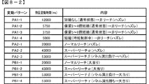
次に、図8−2は、本実施の形態における変動パターンを示している。本実施の形態では、可変表示結果が「ハズレ」となる場合のうち、飾り図柄の可変表示態様が「非リーチ」である場合と「リーチ」である場合のそれぞれに対応して、複数の変動パターンが予め用意されている。尚、可変表示結果が「ハズレ」で飾り図柄の可変表示態様が「非リーチ」である場合に対応した変動パターンは、非リーチ変動パターン(「非リーチハズレ変動パターン」ともいう)と称され、可変表示結果が「ハズレ」で飾り図柄の可変表示態様が「リーチ」である場合に対応した変動パターンは、リーチ変動パターン(「リーチハズレ変動パターン」ともいう)と称される。また、非リーチ変動パターンとリーチ変動パターンは、可変表示結果が「ハズレ」となる場合に対応したハズレ変動パターンに含まれる。可変表示結果が「大当り」である場合に対応した変動パターンは、大当り変動パターンと称される。 Next, FIG. 8-2 shows a variation pattern in the present embodiment. In the present embodiment, among the cases where the variable display result is “losing”, a plurality of fluctuations corresponding to each of the case where the decorative display variable display mode is “non-reach” and “reach” A pattern is prepared in advance. The variation pattern corresponding to the case where the variable display result is “losing” and the decorative symbol variable display mode is “non-reach” is called a non-reach variation pattern (also referred to as “non-reach loss variation pattern”) and is variable. The variation pattern corresponding to the case where the display result is “losing” and the decorative symbol variable display mode is “reach” is referred to as a reach variation pattern (also referred to as “reach loss variation pattern”). The non-reach variation pattern and the reach variation pattern are included in the loss variation pattern corresponding to the case where the variable display result is “lost”. A variation pattern corresponding to the case where the variable display result is “big hit” is referred to as a big hit variation pattern.
大当り変動パターンやリーチ変動パターンには、ノーマルリーチのリーチ演出が実行されるノーマルリーチ変動パターンと、スーパーリーチα、スーパーリーチβ、スーパーリーチγといったスーパーリーチのリーチ演出が実行されるスーパーリーチ変動パターンとがある。尚、本実施の形態では、ノーマルリーチ変動パターンを1種類のみしか設けていないが、本発明はこれに限定されるものではなく、スーパーリーチと同様に、ノーマルリーチα、ノーマルリーチβ、…のように、複数のノーマルリーチ変動パターンを設けても良い。また、スーパーリーチ変動パターンでも、4以上のスーパーリーチ変動パターンを設けても良い。 The big hit fluctuation pattern and the reach fluctuation pattern include a normal reach fluctuation pattern in which a reach of normal reach is executed, and a super reach fluctuation pattern in which a reach of super reach such as super reach α, super reach β, and super reach γ is executed. is there. In the present embodiment, only one type of normal reach variation pattern is provided.However, the present invention is not limited to this, and, like super reach, normal reach α, normal reach β,... A plurality of normal reach fluctuation patterns may be provided. Further, four or more super reach variation patterns may be provided.
図8−2に示すように、本実施の形態におけるノーマルリーチのリーチ演出が実行されるノーマルリーチ変動パターンの特図変動時間については、スーパーリーチ変動パターンであるスーパーリーチα、スーパーリーチβ、スーパーリーチγよりも短く設定されている。また、本実施の形態におけるスーパーリーチα、スーパーリーチβ、スーパーリーチγといったスーパーリーチのリーチ演出が実行されるスーパーリーチ変動パターンの特図変動時間については、スーパーリーチβ及びスーパーリーチγのスーパーリーチ演出が実行される変動パターンの方が、スーパーリーチαのスーパーリーチ演出が実行される変動パターンよりも特図変動時間が長く設定されている。 As shown in FIG. 8B, the special reach fluctuation time of the normal reach fluctuation pattern in which the reach effect of the normal reach in the present embodiment is executed is the super reach fluctuation pattern super reach α, super reach β, and super reach γ. Is set shorter. In addition, regarding the special figure variation time of the super reach variation pattern in which super reach reach production such as super reach α, super reach β, and super reach γ in the present embodiment is performed, the super reach β and super reach γ super reach The variation pattern in which the effect is executed is set to have a longer special figure variation time than the variation pattern in which the super reach effect of the super reach α is executed.
尚、本実施の形態では、前述したように、スーパーリーチγ、スーパーリーチβ、スーパーリーチα、ノーマルリーチの順に可変表示結果が「大当り」となる大当り信頼度が高くなるように設定されているため、ノーマルリーチ変動パターン及びスーパーリーチ変動パターンにおいては変動時間が長いほど大当り信頼度が高くなっている。尚、例えば、スーパーリーチαの信頼度は、大当りとなるときにスーパーリーチαが出現する確率を、当該スーパーリーチαが出現する全確率(ハズレとなる場合にスーパーリーチαが実行される確率と大当りとなるときにスーパーリーチαが実行される確率との合計)で除した値(割合)である。 In the present embodiment, as described above, since the variable display result is “big hit” in the order of super reach γ, super reach β, super reach α, and normal reach, the big hit reliability is set to be high. In the normal reach variation pattern and the super reach variation pattern, the longer the variation time, the higher the big hit reliability. Note that, for example, the reliability of the super reach α is the probability that the super reach α will appear when it is a big hit, and the total probability that the super reach α will appear (the probability that the super reach α will be executed if it is lost). It is a value (ratio) divided by the sum of the probability that super reach α will be executed when it is a big hit.
尚、本実施の形態においては、これら変動パターンを、例えば、非リーチの種別や、ノーマルリーチの種別や、スーパーリーチの種別等のように、変動パターンの種別を先に決定してから、該決定した種別に属する変動パターンに属する変動パターンから実行する変動パターンを決定するのではなく、これらの種別を決定することなしに変動パターン判定用の乱数値MR3のみを用いて決定するようにしているが、本発明はこれに限定されるものではなく、例えば、変動パターン判定用の乱数値MR3に加えて、変動パターン種別判定用の乱数値を設けて、これら変動パターン種別判定用の乱数値から変動パターンの種別を先に決定してから、該決定した種別に属する変動パターンに属する変動パターンから実行する変動パターンを決定するようにしても良い。 In the present embodiment, these variation patterns are determined after the variation pattern type is first determined, such as a non-reach type, a normal reach type, a super reach type, or the like. The variation pattern to be executed is not determined from the variation pattern belonging to the variation pattern belonging to the selected type, but is determined using only the random value MR3 for variation pattern determination without determining these types. The present invention is not limited to this. For example, in addition to the random value MR3 for determining the variation pattern, a random value for determining the variation pattern type is provided, and the variation from the random value for determining the variation pattern type is changed. After determining the pattern type first, the variation pattern to be executed is determined from the variation pattern belonging to the variation pattern belonging to the determined type. Unishi and may be.
また、ROM101には、変動パターン判定用の乱数値MR3に基づいて変動パターンを決定するための変動パターン判定テーブルも記憶されており、変動パターンを、事前決定結果に応じて前述した複数種類のうちのいずれかの変動パターンに決定する。
The
具体的には、変動パターン判定テーブルとしては、図8−3に示すような変動パターン判定テーブルが予め用意されている。大当り種別が「確変大当り」である場合と、大当り種別が「非確変大当り」である場合と、「ハズレ」である場合と、に応じた判定値数が予め用意されている。具体的には、「確変大当り」の場合、ノーマルリーチに対して5個の判定値が割り当てられ、スーパーリーチαに対して10個の判定値が割り当てられ、スーパーリーチβに対して35個の判定値が割り当てられ、スーパーリーチγに対して50個の判定値が割り当てられている。「非確変大当り」の場合、ノーマルリーチに対して5個の判定値が割り当てられ、スーパーリーチαに対して50個の判定値が割り当てられ、スーパーリーチβに対して35個の判定値が割り当てられ、スーパーリーチγに対して10個の判定値が割り当てられている。「ハズレ」の場合、非リーチに対して70個の判定値が割り当てられ、ノーマルリーチに対して20個の判定値が割り当てられ、スーパーリーチαに対して7個の判定値が割り当てられ、スーパーリーチβに対して2個の判定値が割り当てられ、スーパーリーチγに対して1個の判定値が割り当てられている。このように、大当りの場合、ハズレの場合よりも高い割合でスーパーリーチα、β、γが選択され、確変大当りの場合、非確変大当りの場合よりも高い割合でスーパーリーチγが選択されるようになっている。また、ハズレの場合、スーパーリーチαはスーパーリーチβ、γよりも高い割合で選択される。 Specifically, a variation pattern determination table as shown in FIG. 8C is prepared in advance as the variation pattern determination table. The number of determination values corresponding to the case where the big hit type is “probable big hit”, the case where the big hit type is “non-probable big hit”, and the case where “lost” is prepared. Specifically, in the case of “probability big hit”, 5 determination values are assigned to normal reach, 10 determination values are assigned to super reach α, and 35 determination values are assigned to super reach β. A value is assigned and 50 decision values are assigned to the super reach γ. In the case of “non-probable big hit”, 5 decision values are assigned to normal reach, 50 decision values are assigned to super reach α, and 35 decision values are assigned to super reach β. Ten determination values are assigned to the super reach γ. In the case of “losing”, 70 decision values are assigned to non-reach, 20 decision values are assigned to normal reach, and 7 decision values are assigned to super reach α. Two determination values are assigned to β, and one determination value is assigned to super reach γ. Thus, in the case of big hit, super reach α, β, γ is selected at a higher rate than in the case of loss, and in the case of probability variable big hit, super reach γ is selected at a higher rate than in the case of non-probable big hit. It has become. In the case of loss, the super reach α is selected at a higher ratio than the super reach β and γ.
尚、特に詳細な図示はしないが、「ハズレ」である場合には、合計保留記憶数が2個以下である場合と、合計保留記憶数が3個である場合と、合計保留記憶数が4個である場合と、遊技状態が時短制御の実施されている高ベース状態である場合と、に応じた判定値数が予め用意されている。例えば、短縮なしの非リーチハズレの変動パターン(PA1−1)よりも非リーチハズレの変動パターン(PA1−2)の方が変動時間は短く、更に、変動パターン(PA1−2)よりも非リーチハズレの変動パターン(PA1−3)の方が変動時間は短い。よって、保留記憶数が増加した場合には、変動時間が短い非リーチハズレの変動パターンが決定されることにより、保留記憶が消化されやすくなって、保留記憶数が上限数である4に達しているときに始動入賞することで、保留記憶がなされない無駄な始動入賞が発生し難くなるようになるとともに、保留記憶数が減少した場合には、変動時間が長い短縮なしの非リーチハズレの変動パターン(PA1−1)が決定されることによって、可変表示の時間が長くなることにより、可変表示が実行されないことによる遊技の興趣低下を防ぐことができるようになっている。 Although not shown in detail in detail, in the case of “losing”, when the total number of reserved memories is 2 or less, when the total number of reserved memories is 3, and when the total number of reserved memories is 4 The number of determination values corresponding to the case where the number is individual and the case where the gaming state is a high base state where time-shortening control is performed are prepared in advance. For example, the non-reach loss variation pattern (PA1-2) has a shorter variation time than the non-reach loss variation pattern (PA1-1) without shortening, and further, the non-reach loss variation more than the variation pattern (PA1-2). The pattern (PA1-3) has a shorter variation time. Therefore, when the number of reserved memories increases, the non-reach loss variation pattern with a short variation time is determined, so that the reserved memories are easily digested, and the number of reserved memories reaches the upper limit number of 4. Occasionally, the winning prize makes it difficult to generate useless starting prizes that are not reserved, and when the number of reserved memories decreases, the fluctuation pattern of non-reach loss without shortening with a long fluctuation time ( By determining PA1-1), it is possible to prevent a decrease in the interest of the game due to the fact that the variable display is not executed by increasing the time for variable display.
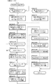
次に、図8−4は、図7に示された演出制御プロセス処理における可変表示開始設定処理(S171)を示すフローチャートである。 Next, FIG. 8-4 is a flowchart showing a variable display start setting process (S171) in the effect control process shown in FIG.
図8−4に示す可変表示開始設定処理において、演出制御用CPU120は、まず、第1変動開始コマンド受信フラグがセットされているか否かを判定する(009SGS271)。第1変動開始コマンド受信フラグがセットされている場合は、始動入賞時受信コマンドバッファ(図示略)における第1特図保留記憶のバッファ番号「1−0」〜「1−4」に対応付けて格納されている各種コマンドデータと各種フラグを、バッファ番号1個分ずつ上位にシフトする(009SGS272)。尚、バッファ番号「1−0」の内容については、シフトする先が存在しないためにシフトすることはできないので消去される。
In the variable display start setting process shown in FIG. 8-4, the
具体的には、第1特図保留記憶のバッファ番号「1−1」に対応付けて格納されている各種コマンドデータと各種フラグをバッファ番号「1−0」に対応付けて格納するようにシフトし、第1特図保留記憶のバッファ番号「1−2」に対応付けて格納されている各種コマンドデータと各種フラグをバッファ番号「1−1」に対応付けて格納するようにシフトし、第1特図保留記憶のバッファ番号「1−3」に対応付けて格納されている各種コマンドデータと各種フラグをバッファ番号「1−2」に対応付けて格納するようにシフトし、第1特図保留記憶のバッファ番号「1−4」に対応付けて格納されている各種コマンドデータと各種フラグをバッファ番号「1−3」に対応付けて格納するようにシフトする。 Specifically, various command data and various flags stored in association with the buffer number “1-1” in the first special figure hold memory are shifted so as to be stored in association with the buffer number “1-0”. Then, the various command data and various flags stored in association with the buffer number “1-2” in the first special figure reservation memory are shifted so as to be stored in association with the buffer number “1-1”. Various command data and various flags stored in association with the buffer number “1-3” in the 1 special figure hold memory are shifted so as to be stored in association with the buffer number “1-2”. Various command data and various flags stored in association with the buffer number “1-4” in the pending storage are shifted so as to be stored in association with the buffer number “1-3”.
また、009SGS271において第1変動開始コマンド受信フラグがセットされていない場合は、第2変動開始コマンド受信フラグがセットされているか否かを判定する(009SGS273)。第2変動開始コマンド受信フラグがセットされていない場合は、処理を終了し、第2変動開始コマンド受信フラグがセットされている場合は、始動入賞時受信コマンドバッファ(図示略)における第2特図保留記憶のバッファ番号「2−0」〜「2−4」に対応付けて格納されている各種コマンドデータと各種フラグを、バッファ番号1個分ずつ上位にシフトする(009SGS274)。尚、バッファ番号「2−0」の内容については、シフトする先が存在しないためにシフトすることはできないので消去される。 If the first change start command reception flag is not set in 009SGS271, it is determined whether the second change start command reception flag is set (009SGS273). If the second variation start command reception flag is not set, the processing is terminated, and if the second variation start command reception flag is set, the second special chart in the start winning reception command buffer (not shown). The various command data and the various flags stored in association with the buffer numbers “2-0” to “2-4” in the pending storage are shifted up by one buffer number (009 SGS274). Note that the contents of the buffer number “2-0” are erased because they cannot be shifted because there is no destination to shift.
具体的には、第2特図保留記憶のバッファ番号「2−1」に対応付けて格納されている各種コマンドデータと各種フラグをバッファ番号「2−0」に対応付けて格納するようにシフトし、第2特図保留記憶のバッファ番号「2−2」に対応付けて格納されている各種コマンドデータと各種フラグをバッファ番号「2−1」に対応付けて格納するようにシフトし、第2特図保留記憶のバッファ番号「2−3」に対応付けて格納されている各種コマンドデータと各種フラグをバッファ番号「2−2」に対応付けて格納するようにシフトし、第2特図保留記憶のバッファ番号「2−4」に対応付けて格納されている各種コマンドデータと各種フラグをバッファ番号「2−3」に対応付けて格納するようにシフトする。 Specifically, various command data and various flags stored in association with the buffer number “2-1” in the second special figure reservation memory are shifted so as to be stored in association with the buffer number “2-0”. Then, the various command data and the various flags stored in association with the buffer number “2-2” in the second special figure reservation memory are shifted so as to be stored in association with the buffer number “2-1”. The second special figure is shifted so that the various command data and the various flags stored in association with the buffer number “2-3” stored in the special figure hold memory are associated with the buffer number “2-2”. Various command data and various flags stored in association with the buffer number “2-4” in the pending storage are shifted so as to be stored in association with the buffer number “2-3”.
009SGS272または009SGS274の実行後、演出制御用CPU120は、変動パターン指定コマンド格納領域から変動パターン指定コマンドを読み出す(009SGS275)。
After execution of 009SGS272 or 009SGS274, the
次いで、表示結果指定コマンド格納領域に格納されているデータ(即ち、受信した表示結果指定コマンド)に応じて飾り図柄の表示結果(停止図柄)を決定する(009SGS276)。この場合、演出制御用CPU120は、表示結果指定コマンドで指定される表示結果に応じた飾り図柄の停止図柄を決定し、決定した飾り図柄の停止図柄を示すデータを飾り図柄表示結果格納領域に格納する。
Next, the display result (stop symbol) of the decorative symbol is determined according to the data stored in the display result specifying command storage area (that is, the received display result specifying command) (009SGS276). In this case, the
尚、この実施の形態では、受信した可変表示結果指定コマンドが確変大当りに該当する可変表示結果指定コマンドである場合において、演出制御用CPU120は、例えば、停止図柄として3図柄が奇数図柄で揃った飾り図柄の組合せ(大当り図柄)を決定する。また、受信した可変表示結果指定コマンドが非確変大当りに該当する可変表示結果指定コマンドである場合において、演出制御用CPU120は、例えば、停止図柄として3図柄が偶数図柄で揃った飾り図柄の組合せ(大当り図柄)を決定する。また、受信した可変表示結果指定コマンドが、ハズレに該当する第1可変表示結果指定コマンドである場合には、停止図柄として3図柄が不揃いとなる飾り図柄の組合せ(ハズレ図柄)を決定する。
In this embodiment, when the received variable display result designation command is a variable display result designation command corresponding to the probability variation big hit, the
これら停止図柄の決定においては、演出制御用CPU120は、例えば、停止図柄を決定するための乱数を抽出し、飾り図柄の組合せを示すデータと数値とが対応付けられている停止図柄判定テーブルを用いて、飾り図柄の停止図柄を決定すれば良い。即ち、抽出した乱数に一致する数値に対応する飾り図柄の組合せを示すデータを選択することによって停止図柄を決定すれば良い。
In determining these stop symbols, the
次いで、演出制御用CPU120は、原点位置検出スイッチ(図示略)がオン状態であるか否か、つまり、可動体32が原点位置に位置しているか否かを判定する(009SGS276A)。原点位置検出スイッチ(図示略)がオン状態ではない、つまり、原点位置に位置していない場合、時短制御が実行されていることを示す時短制御フラグがセットされているか否か、つまり、高ベース状態であるか否かを判定する(009SGS276B)。時短制御フラグがセットされていなければ、昇降モータをオン状態にして可動体32を原点位置に向けて後述する第2速度(低速)で下降させる制御を開始する(009SGS276C)。尚、可動体32を原点位置に向けて下降させる制御は、原点位置検出スイッチ(図示略)がオン状態になるタイミング(例えば、後述する009SGS311など)で終了する。
Next, the
次いで、演出制御用CPU120は、読み出した変動パターン指定コマンドから特定される変動パターンが、スーパーリーチβの変動パターンPA2−3、PB1−3またはスーパーリーチγの変動パターンPB1−4であるか否かを判定する(009SGS277)。変動パターンがスーパーリーチβまたはスーパーリーチγ以外の変動パターンである場合は、変動パターンに対応するプロセステーブルを選択する(009SGS281)。変動パターンがスーパーリーチβまたはスーパーリーチγの変動パターンである場合、各スーパーリーチ変動パターンに対応する複数種類のリーチ演出パターンのうちからいずれかを決定する処理(009SGS278、009SGS279)へ移行する。
Next, the
(リーチ演出)
図8−2に示すように、本実施の形態では、飾り図柄の可変表示の態様がリーチ態様とならずに表示結果が「ハズレ」となる非リーチハズレの変動パターンPA1−1、PA1−2、PA1−3、PA1−4、飾り図柄の可変表示の態様がリーチ態様となって表示結果が「ハズレ」となるリーチハズレの変動パターンPA2−1、表示結果が「大当り」となる変動パターンPB1−1等が用意されている。
(Reach production)
As shown in FIG. 8B, in the present embodiment, the non-reach losing variation patterns PA1-1, PA1-2, in which the decorative display variable display mode is not the reach mode and the display result is “lost”. PA1-3, PA1-4, the variable display mode of the decorative pattern is the reach mode and the display result is “lost”, the change pattern PA2-1 of the reach loss, and the change pattern PB1-1 of which the display result is “big hit” Etc. are prepared.
また、本実施の形態では、ノーマルリーチやスーパーリーチといったリーチ演出が実行されるようになっており、これら各リーチ演出は、大当り状態に制御されることを示唆する示唆演出とも称される。各リーチが実行されたときの信頼度(大当り信頼度)は、図8−3で表すように、スーパーリーチγ並びにスーパーリーチβ、スーパーリーチα、ノーマルリーチの順に高くなっている。尚、大当りとなることが確定するリーチを設けてもよい。 In the present embodiment, reach effects such as normal reach and super reach are executed, and each reach effect is also referred to as a suggestion effect suggesting that the game is controlled to a big hit state. The reliability (big hit reliability) when each reach is executed increases in the order of super reach γ, super reach β, super reach α, and normal reach, as shown in FIG. In addition, you may provide the reach which determines that it becomes a big hit.
また、スーパーリーチγ、スーパーリーチβ、スーパーリーチαは、ノーマルリーチを経由して、該ノーマルリーチよりも大当り信頼度の高いスーパーリーチに発展(昇格)するようになっている。図8−2に示す変動パターンPA2−2、PA2−3、PB1−2、PB1−3、PB1−4等が信頼度が一段階上のスーパーリーチ演出が実行されることに対応した変動パターンとなっているが、信頼度が二段階以上発展する変動パターンを設けてもよいし、スーパーリーチに発展しない変動パターンを設けてもよい。また、ノーマルリーチの変動パターンPA2−1、PB1−1についても、各々複数のリーチ演出のうちからいずれかを決定可能としてもよい。 Further, the super reach γ, the super reach β, and the super reach α are developed (promoted) via the normal reach to a super reach having a higher hit reliability than the normal reach. The fluctuation patterns PA2-2, PA2-3, PB1-2, PB1-3, PB1-4, etc. shown in FIG. However, a variation pattern in which the reliability develops in two or more stages may be provided, or a variation pattern that does not develop into super reach may be provided. Also, the normal reach variation patterns PA2-1 and PB1-1 may each be determined from a plurality of reach effects.
尚、本実施の形態では、CPU103が決定した一の変動パターンに対し、演出制御用CPU120が一のリーチ演出に対応した演出パターンを選択可能な形態を例示したが、本発明はこれに限定されるものではなく、一の変動パターンに対し複数のリーチ演出のうちから一の演出パターンを選択可能とてもよい。
In the present embodiment, an example is shown in which the
本実施の形態では、変動パターンがスーパーリーチγ、スーパーリーチβ、スーパーリーチαである場合、可変表示を開始してから所定期間が経過したタイミングでノーマルリーチ演出が実行され、その後、ハズレ組合せの飾り図柄が仮停止表示されたときに可動体32が原点位置から演出位置へ移動してスーパーリーチ演出に発展(移行)する。そして、スーパーリーチγまたはスーパーリーチβの場合は、スーパーリーチ演出としてバトル演出が開始され、スーパーリーチαの場合は、スーパーリーチ演出としてバトル演出以外の演出が開始される。
In the present embodiment, when the variation pattern is Super Reach γ, Super Reach β, Super Reach α, the normal reach effect is executed at the timing when a predetermined period has elapsed after the start of variable display, and then the combination of the lost combinations When the symbol is temporarily stopped and displayed, the
バトル演出では、例えば、味方キャラクタが敵キャラクタと対決し、味方キャラクタが対決に勝利すれば大当りが報知され、対決に敗北すればハズレが報知される。バトル演出には、味方キャラクタが敗北した後、可動体32が演出位置から下降して原点位置まで戻る前にハズレ組合せの飾り図柄が停止表示されてハズレや大当りが報知される場合がある(図8−12参照)。
In the battle effect, for example, a teammate character confronts an enemy character, and if the teammate character wins the confrontation, a jackpot is notified, and if the confrontation is defeated, a loss is notified. In the battle production, after the teammate character is defeated, before the
また、味方キャラクタが敗北した後、ハズレ組合せの飾り図柄が停止表示される前に可動体32が演出位置から下降して原点位置まで戻るときに、仮停止表示されているハズレ組合せの飾り図柄(飾り図柄画像)が変化(完全縮小または完全破壊)することで、一度敗北した味方キャラクタが再度敵キャラクタと対決する復活演出(救済演出)に発展(移行)し、該復活演出の実行後に、最終的に大当りが報知される場合とハズレが報知される場合とがある(図8−14参照)。
Further, after the teammate character is defeated, when the
また、味方キャラクタが敗北した後、ハズレ組合せの飾り図柄が停止表示される前に可動体32が演出位置から下降して原点位置まで戻るときに、仮停止表示されているハズレ組合せの飾り図柄(飾り図柄画像)が変化(半分縮小または半分破壊)するが、変化前の態様に戻ってしまい、復活演出に発展することなくハズレが報知される場合や(図8−13参照)、味方キャラクタが敗北した後、ハズレ組合せの飾り図柄が停止表示される前に可動体32が演出位置から下降して原点位置まで戻るときに、仮停止表示されているハズレ組合せの飾り図柄(飾り図柄画像)が変化せず、復活演出に発展することなくハズレが報知される場合(図8−12参照)等がある。
Further, after the teammate character is defeated, when the
このように、ハズレ組合せの飾り図柄が停止表示される前に可動体32が演出位置から下降して原点位置まで戻る動作制御が実行されることで、復活演出が実行される可能性があることが示唆される。つまり、この可動体32の下降動作は、復活演出の実行を示唆する示唆演出である。
In this way, there is a possibility that the revival effect may be executed by performing the operation control in which the
図8−5(A)は、バトル演出に対応する複数種類のリーチ演出パターン1〜9が示されている。リーチ演出パターン1は、バトル演出に敗北した後、可動体32は下降せず、ハズレ組合せの飾り図柄も変化しないので、復活演出が実行されないリーチ演出パターンである。リーチ演出パターン2は、バトル演出に敗北した後、可動体32は演出位置から原点位置へ下降するときに、ハズレ組合せの飾り図柄は変化しないので、復活演出が実行されないリーチ演出パターンである。リーチ演出パターン3は、バトル演出に敗北した後、可動体32が演出位置から原点位置へ下降するときに、ハズレ組合せの飾り図柄が半分破壊されるが完全破壊(変化)されないので、復活演出が実行されないリーチ演出パターンである。リーチ演出パターン4は、バトル演出に敗北した後、可動体32が演出位置から原点位置へ下降するときに、ハズレ組合せの飾り図柄が半分縮小されるが完全縮小(変化)されないので、復活演出が実行されないリーチ演出パターンである。リーチ演出パターン5は、バトル演出に敗北した後、可動体32が演出位置から原点位置へ下降するときに、ハズレ組合せの飾り図柄が完全破壊(変化)されることで復活演出が実行されるが、最終的にハズレが報知されるリーチ演出パターンである。リーチ演出パターン6は、バトル演出に敗北した後、可動体32が演出位置から原点位置へ下降するときに、ハズレ組合せの飾り図柄が完全縮小(変化)されることで復活演出が実行されるが、最終的にハズレが報知されるリーチ演出パターンである。リーチ演出パターン7は、バトル演出に敗北した後、可動体32が演出位置から原点位置へ下降するときに、ハズレ組合せの飾り図柄が完全に破壊(変化)されることで復活演出が実行され、最終的に大当りが報知されるリーチ演出パターンである。リーチ演出パターン8は、バトル演出に敗北した後、可動体32が演出位置から原点位置へ下降するときに、ハズレ組合せの飾り図柄が完全に縮小(変化)されることで復活演出が実行され、最終的に大当りが報知されるリーチ演出パターンである。リーチ演出パターン9は、バトル演出に勝利するので、可動体32が演出位置から原点位置へ下降せず、ハズレ組合せの飾り図柄は変化せず、復活演出も実行されないスーパーリーチγに対応したリーチ演出パターンである。
FIG. 8-5 (A) shows a plurality of types of
また、図8−5(B)に示すように、バトル演出に敗北した後、可動体32が演出位置から原点位置へ下降するときの下降速度は、リーチ演出パターン2〜6(ハズレ)の場合及びリーチ演出パターン7,8(大当り)の場合では共通の第1速度(高速)である。つまり、ハズレ組合せの飾り図柄が停止表示される前に可動体32が下降して復活演出の実行が示唆された後に大当りまたはハズレとなる場合でも、可動体32の動作態様は共通であるため、可動体32の下降動作態様により大当りになるか否かを予測し難くなっている。これに対し、リーチ演出パターン1,9の場合は、第1速度よりも遅い第2速度(低速)とされている。
Also, as shown in FIG. 8-5 (B), after defeating the battle effect, the descending speed when the
このように本実施の形態では、リーチ演出パターン1,9のように、大当りやハズレの報知が行われた後(例えば、確定飾り図柄が停止表示された後)に可動体32が原点位置に戻る場合と、リーチ演出パターン2〜8のように、大当りやハズレの報知が行われる前(例えば、確定飾り図柄が停止表示される前)に可動体32が原点位置に戻る場合とで、下降速度が異なっている。また、リーチ演出パターン2〜6(ハズレ)の場合でも、リーチ演出パターン7,8(大当り)の場合でも、可動体32の下降速度を同じ高速とする(下降動作態様を共通とする)ことで、下降速度により大当りになるか否かを予測できないようにしている。
As described above, in the present embodiment, as in the case of the
また、可動体32の下降に連動してハズレ組合せの飾り図柄の態様を変化させないリーチ演出パターン2の場合でも、可動体32の下降に連動してハズレ組合せの飾り図柄の態様を変化させるリーチ演出パターン3〜8の場合でも、可動体32の下降速度を同じ高速とする(下降動作態様を共通とする)ことで、下降速度により復活演出が実行されるか否かを予測できないようにしている。
Further, even in the case of the
また、リーチ演出パターン3,5,7の場合、可動体32の下降に連動してハズレ組合せの飾り図柄が破壊されるように表示する一方で、リーチ演出パターン4,6,8の場合、可動体32の下降に連動してハズレ組合せの飾り図柄が縮小されるように表示する。つまり、演出制御用CPU120は、ハズレ組合せの飾り図柄の変化態様が異なる複数種類のリーチ演出パターンのうちからいずれかのリーチ演出パターンを選択可能である。
In the case of the
また、本実施の形態では、バトル演出に敗北した後、大当りやハズレの報知が行われる前に可動体32が演出位置から原点位置へ下降する場合、表示領域5Eに表示されている背景表示画像が、リーチ演出用背景画像009SG011から特殊背景画像009SG012に切り替わり、その後、復活演出が実行されない場合は、スーパーリーチ演出が実行される前に表示されていた通常背景画像009SG010に戻る一方で、復活演出が実行される場合は、復活演出用背景画像009SG013に切り替わり、復活演出の終了後に通常背景画像009SG010または大当り用背景画像(図示略)に切り替わる。
Further, in the present embodiment, after defeating the battle effect, the background display image displayed in the
また、演出制御用CPU120は、読み出した変動パターン指定コマンドがスーパーリーチγまたはスーパーリーチβの変動パターンである場合、図8−6に示すリーチ演出パターン決定用テーブルを用いて、リーチ演出パターン1〜9のうちから変動パターンに応じたいずれかのリーチ演出パターンを決定する。
In addition, when the read variation pattern designation command is a super reach γ or super reach β variation pattern, the
図8−6は、リーチ演出パターン決定用テーブルの構成例を示す図である。尚、本実施の形態では、リーチ演出パターン決定用乱数は、1〜100の範囲の乱数とされていて1〜100の範囲のいずれかの値が抽出される。 FIG. 8-6 is a diagram illustrating a configuration example of a reach effect pattern determination table. In the present embodiment, the reach effect pattern determination random number is a random number in the range of 1 to 100, and any value in the range of 1 to 100 is extracted.
図8−6に示すように、リーチ演出パターン決定用テーブルでは、リーチ演出パターン1〜9のそれぞれに対して、スーパーリーチβハズレの場合、スーパーリーチβ大当りの場合、スーパーリーチγ大当りの場合、のそれぞれに異なる判定値が、図8−6に示す判定値数となるように割り当てられている。具体的には、スーパーリーチβハズレの場合、リーチ演出パターン1に対して30個の判定値が割り当てられ、リーチ演出パターン2に対して25個の判定値が割り当てられ、リーチ演出パターン3に対して20個の判定値が割り当てられ、リーチ演出パターン4に対して15個の判定値が割り当てられ、リーチ演出パターン5に対して7個の判定値が割り当てられ、リーチ演出パターン6に対して3個の判定値が割り当てられている。また、スーパーリーチβ大当りの場合、リーチ演出パターン7に対して40個の判定値が割り当てられ、リーチ演出パターン8に対して60個の判定値が割り当てられている。また、スーパーリーチγ大当りの場合、リーチ演出パターン9に対して100個の判定値が割り当てられている。
As shown in FIG. 8-6, in the reach effect pattern determination table, for each of the
このように、変動パターンがスーパーリーチβの場合において、ハズレのときには、復活演出が実行されるリーチ演出パターン5,6よりも高い割合で復活演出が実行されないリーチ演出パターン1〜4の実行が決定され、大当りのときには、復活演出が実行されるリーチ演出パターン7,8のいずれかの実行が決定される。
As described above, when the variation pattern is Super Reach β, the execution of the
また、ハズレのときには、可動体32の下降に応じてハズレ組合せの飾り図柄が破壊されるリーチ演出パターン3,5が、可動体32の下降に応じてハズレ組合せの飾り図柄が縮小されるリーチ演出パターン4,6よりも高い割合で決定される。また、可動体32の下降に応じてハズレ組合せの飾り図柄が半分破壊されるリーチ演出パターン3が、可動体32の下降に応じてハズレ組合せの飾り図柄が完全破壊されるリーチ演出パターン5よりも高い割合で決定される。また、可動体32の下降に応じてハズレ組合せの飾り図柄が半分縮小されるリーチ演出パターン4が、可動体32の下降に応じてハズレ組合せの飾り図柄が完全縮小されるリーチ演出パターン6よりも高い割合で決定される。
In the case of a loss, the
よって、大当り信頼度は、可動体32の下降に応じてハズレ組合せの飾り図柄が破壊されるリーチ演出パターンよりも可動体32の下降に応じてハズレ組合せの飾り図柄が縮小されるリーチ演出パターンの方が高く、ハズレ組合せの飾り図柄が半分縮小されるリーチ演出パターンよりも可動体32の下降に応じてハズレ組合せの飾り図柄が完全縮小されるリーチ演出パターンの方が高く、ハズレ組合せの飾り図柄が半分破壊されるリーチ演出パターンよりも可動体32の下降に応じてハズレ組合せの飾り図柄が完全破壊されるリーチ演出パターンの方が高くなっている。
Therefore, the big hit reliability is a reach effect pattern in which the decorative pattern of the lost combination is reduced according to the descent of the
つまり、リーチ演出パターン9,8,7,6,5,4,3,2,1の順に大当り信頼度が高くなるように設定されているとともに、ハズレ組合せの飾り図柄の変化態様(例えば、半分縮小、完全縮小、半分破壊、完全縮小など)に応じて大当りとなる割合が異なっている。
In other words, the jackpot reliability is set to increase in the order of
図8−4に戻り、009SGS277において、変動パターンがスーパーリーチβまたはスーパーリーチγの変動パターンである場合は、リーチ演出パターン決定用乱数を抽出し、図8−6に示すリーチ演出パターン決定用テーブルを用いて、リーチ演出パターンをリーチ演出パターン1〜9のいずれかに決定し(009SGS278)、変動パターン及び決定したリーチ演出パターン1〜9のいずれかに対応するプロセステーブルを選択する(009SGS279)。
8-4, in 009SGS277, when the variation pattern is a variation pattern of super reach β or super reach γ, a reach effect pattern determining random number is extracted, and a reach effect pattern determining table shown in FIG. 8-6 is obtained. The reach effect pattern is determined to be one of
009SGS279または009SGS281の処理を実行した後は、選択したプロセステーブルのプロセスデータ1におけるプロセスタイマをスタートさる(009SGS382)。
After executing the process of 009SGS279 or 009SGS281, the process timer in the
プロセステーブルには、画像表示装置5の表示を制御するための表示制御実行データ、各LEDの点灯を制御するためのランプ制御実行データ、スピーカ8L,8Rから出力する音の制御するための音制御実行データや、プッシュボタン31Bやスティックコントローラ31Aの操作を制御するための操作部制御実行データ等が、各プロセスデータn(1〜N番まで)に対応付けて時系列に順番配列されている。
The process table includes display control execution data for controlling the display of the
次いで、演出制御用CPU120は、プロセスデータ1の内容(表示制御実行データ1、ランプ制御実行データ1、音制御実行データ1、操作部制御実行データ1)に従って演出装置(演出用部品としての画像表示装置5、演出用部品としての各種ランプ及び演出用部品としてのスピーカ8L,8R、操作部(プッシュボタン31B、スティックコントローラ31A等))の制御を実行する(009SGS283)。例えば、画像表示装置5において変動パターンに応じた画像を表示させるために、表示制御部123に指令を出力する。また、各種ランプを点灯/消灯制御を行わせるために、ランプ制御基板14に対して制御信号(ランプ制御実行データ)を出力する。また、スピーカ8L,8Rからの音声出力を行わせるために、音声制御基板13に対して制御信号(音番号データ)を出力する。
Next, the
尚、009SGS279または009SGS281を実行した後に、レベルアップ予告やセリフ予告といった予告演出決定処理を実行し、実行が決定された場合には、予告演出開始待ちタイマに、予告演出開始までの期間として、決定した予告演出の種別に対応する期間を設定するようにしてもよい。 In addition, after executing 009SGS279 or 009SGS281, a notice effect determination process such as a level-up notice or a serif notice is executed. When execution is decided, the notice effect start waiting timer is set as a period until the notice effect start. It is also possible to set a period corresponding to the type of the notice effect.
そして、可変表示時間タイマに、変動パターン指定コマンドで特定される変動時間に相当する値を設定する(009SGS284)。また、可変表示制御タイマに所定時間を設定する(009SGS285)。尚、所定時間は例えば30msであり、演出制御用CPU120は、所定時間が経過する毎に左中右の飾り図柄の表示状態を示す画像データをVRAMに書き込み、表示制御部123がVRAMに書き込まれた画像データに応じた信号を画像表示装置5に出力し、画像表示装置5が信号に応じた画像を表示することによって飾り図柄の変動が実現される。次いで、演出制御プロセスフラグの値を可変表示中演出処理(S172)に対応した値にする(009SGS286)。
Then, a value corresponding to the variation time specified by the variation pattern designation command is set in the variable display time timer (009SGS284). Further, a predetermined time is set in the variable display control timer (009SGS285). The predetermined time is, for example, 30 ms, and the
図8−7は、演出制御プロセス処理における可変表示中演出処理(S172)を示すフローチャートである。可変表示中演出処理において、演出制御用CPU120は、プロセスタイマ、可変表示時間タイマ、可変表示制御タイマのそれぞれの値を−1する(009SGS301,009SGS302,009SGS303)。
FIG. 8-7 is a flowchart showing the variable display effect process (S172) in the effect control process. In the variable display effect process, the
次いで、演出制御用CPU120は、可動体32の上昇開始タイミングであるか否か、つまり、リーチ演出パターン1〜9のいずれかを実行中でスーパーリーチ演出に発展するタイミングであるか否かを判定し(009SGS304)、可動体32の上昇開始タイミングである場合は、昇降モータ(図示略)をオン状態にして可動体32を原点位置から演出位置へ上昇させる制御を開始する(009SGS305)。
Next, the
可動体32の上昇開始タイミングでない場合及び009SGS305の処理を実行した後は、可動体32の上昇終了タイミングであるか否か、つまり、可動体32の上昇制御を実行中で可動体32が演出位置に到達したタイミングであるか否かを判定し(009SGS306)、可動体32の上昇終了タイミングである場合は、昇降モータ(図示略)をオフ状態にして可動体32を演出位置に停止させる(009SGS307)。
When it is not the rising start timing of the
可動体32の上昇終了タイミングでない場合及び009SGS307の処理を実行した後は、可動体32の下降開始タイミングであるか否か、つまり、リーチ演出パターン2〜8のいずれかを実行中で可動体32を原点位置に戻すタイミングであるか否かを判定し(009SGS308)、可動体32の下降開始タイミングである場合は、昇降モータ(図示略)をオン状態にして、実行中のリーチ演出パターン2〜8に応じた第1速度(高速)で可動体32を演出位置から原点位置へ下降させる制御を開始する(009SGS309)。
If it is not the rising end timing of the
可動体32の下降開始タイミングでない場合及び009SGS309の処理を実行した後は、可動体32の下降終了タイミングであるか否か、つまり、可動体32の下降制御を実行中で可動体32が原点位置に到達したタイミングであるか否かを判定し(009SGS310)、可動体32の下降終了タイミングである場合は、昇降モータ(図示略)をオフ状態にして可動体32を原点位置に停止させる(009SGS311)。
If it is not the lowering start timing of the
可動体32の下降終了タイミングでない場合及び009SGS311の処理を実行した後は、飾り図柄の変化開始タイミングであるか否か、つまり、飾り図柄の変化を伴うリーチ演出パターン3〜8に基づいて可動体32の下降制御を実行中であり、飾り図柄を変化させるタイミングであるか否かを判定し(009SGS312)、飾り図柄の変化開始タイミングである場合は、仮停止表示しているハズレ組合せの飾り図柄の破壊または縮小表示を開始する(009SGS313)。
If it is not the descent end timing of the
飾り図柄の変化開始タイミングでない場合及び009SGS313の処理を実行した後は、飾り図柄の変化終了タイミングであるか否か、つまり、飾り図柄を変化させる表示制御を実行中であり、飾り図柄の変化を終了させるタイミングであるか否かを判定し(009SGS314)、飾り図柄の変化終了タイミングである場合は、リーチ演出パターン3〜P8に対応した態様で飾り図柄の変化を終了する(009SGS315)。具体的には、リーチ演出パターン3,4の場合は、飾り図柄が半分破壊または半分縮小したタイミングで飾り図柄を元の態様に復帰させ、リーチ演出パターン5〜8の場合は、飾り図柄が完全破壊または完全縮小したタイミングで飾り図柄を消去する。
If it is not the decorative pattern change start timing and after the processing of 009SGS313, whether or not it is the decorative pattern change end timing, that is, display control for changing the decorative pattern is being executed, It is determined whether or not it is a timing to end (009SGS314), and if it is a decorative symbol change end timing, the decorative symbol change is terminated in a manner corresponding to the
飾り図柄の変化終了タイミングでない場合及び009SGS315の処理を実行した後は、背景画像の変化開始タイミングであるか否か、つまり、リーチ演出パターン1〜9に基づいて可動体32の下降制御を実行中であり、該可動体32の下降に応じて背景画像を変化させるタイミングであるか否かを判定し(009SGS316)、背景画像の変化開始タイミングである場合は、実行中のリーチ演出パターン1〜9に応じた態様で背景画像の変化表示を開始する(009SGS317)。
When it is not the decorative pattern change end timing and after executing the process 009SGS315, whether or not it is the change start timing of the background image, that is, the lowering control of the
背景画像の変化開始タイミングでない場合及び009SGS317の処理を実行した後は、背景画像の変化終了タイミングであるか否か、つまり、背景画像を変化させる表示制御を実行中であり、背景画像の表示変化を終了させるタイミングであるか否かを判定し(009SGS318)、背景画像の変化終了タイミングである場合は、リーチ演出パターン1〜9に対応した態様で背景画像の変化を終了し(009SGS319)、009SGS320に進む。
If it is not the change start timing of the background image and after executing the processing of 009SGS317, whether or not it is the change end timing of the background image, that is, the display control for changing the background image is being executed, and the display change of the background image (009SGS318), and if it is the background image change end timing, the background image change ends in a manner corresponding to the
具体的には、リーチ演出パターン1の場合は、飾り図柄を停止表示した後に、リーチ演出用背景画像009SG011から通常背景画像に切り替える。リーチ演出パターン9の場合は、飾り図柄を停止表示した後に、リーチ演出用背景画像009SG011から大当り用背景画像(図示略)に切り替える。リーチ演出パターン2〜4の場合は、可動体32の下降とともにリーチ演出用背景画像009SG011から特殊背景画像009SG012に漸次切り替えた後、通常背景画像に切り替える。リーチ演出パターン5,6の場合は、可動体32の下降とともにリーチ演出用背景画像009SG011から特殊背景画像009SG012に漸次切り替えた後、復活演出用背景画像009SG013に切り替え、飾り図柄を停止表示した後に、特殊背景画像009SG012から通常背景画像に切り替える。リーチ演出パターン7,8の場合は、可動体32の下降とともにリーチ演出用背景画像009SG011から特殊背景画像009SG012に漸次切り替えた後、復活演出用背景画像009SG013に切り替え、飾り図柄を停止表示した後に、特殊背景画像009SG012から大当り用背景画像に切り替える。
Specifically, in the case of the
009SGS320において演出制御用CPU120は、プロセスタイマがタイマアウトしたか否か確認する。プロセスタイマがタイマアウトしていたら、プロセスデータの切り替えを行う(009SGS321)。即ち、プロセステーブルにおける次に設定されているプロセスタイマ設定値をプロセスタイマに設定することによってプロセスタイマをあらためてスタートさせる(009SGS322)。また、その次に設定されている表示制御実行データ、ランプ制御実行データ、音制御実行データ、操作部制御データ等にもとづいて演出装置(演出用部品)に対する制御状態を変更する(009SGS323)。一方、プロセスタイマがタイマアウトしていない場合は、プロセスタイマに対応するプロセスデータの内容(表示制御実行データ、ランプ制御実行データ、音制御実行データ、操作部制御データ等)に従って演出装置(演出用部品)の制御を実行する(009SGS324)。
In 009SGS320, the
009SGS323または009SGS324の処理を実行した後は、可変表示制御タイマがタイマアウトしているか否かを確認する(009SGS325)。可変表示制御タイマがタイマアウトしている場合には、演出制御用CPU120は、左中右の飾り図柄の次表示画面(前回の飾り図柄の表示切り替え時点から30ms経過後に表示されるべき画面)の画像データを作成し、VRAMの所定領域に書き込む(009SGS326)。そのようにして、画像表示装置5において、飾り図柄の変動制御が実現される。表示制御部123は、設定されている背景画像等の所定領域の画像データと、プロセステーブルに設定されている表示制御実行データにもとづく画像データとを重畳したデータに基づく信号を画像表示装置5に出力する。そのようにして、画像表示装置5において、飾り図柄の変動における背景画像、キャラクタ画像及び飾り図柄が表示される。また、可変表示制御タイマに所定値を再セットする(009SGS327)。
After executing the process of 009SGS323 or 009SGS324, it is confirmed whether or not the variable display control timer has timed out (009SGS325). When the variable display control timer has timed out, the
また、可変表示制御タイマがタイマアウトしていない場合または009SGS327の処理の実行後、演出制御用CPU120は、可変表示時間タイマがタイマアウトしているか否か確認する(009SGS328)。可変表示時間タイマがタイマアウトしていれば、演出制御プロセスフラグの値を特図当り待ち処理(S176)に応じた値に更新する(009SGS330)。可変表示時間タイマがタイマアウトしていなくても、図柄確定指定コマンドを受信したことを示す確定コマンド受信フラグがセットされていたら、演出制御プロセスフラグの値を特図当り待ち処理(S176)に応じた値に更新する(009SGS329)。可変表示時間タイマがタイマアウトしていなくても図柄確定指定コマンドを受信したら変動を停止させる制御に移行するので、例えば、基板間でのノイズ等に起因して長い変動時間を示す変動パターン指定コマンドを受信したような場合でも、正規の変動時間経過時(特別図柄の変動終了時)に、飾り図柄の変動を終了させることができる。
When the variable display control timer has not timed out or after execution of the process of 009SGS327, the
(バトル演出の演出動作例)
次に、スーパーリーチ演出の演出動作例について、図8−8〜図8−14に基づいて説明する。図8−8は、(A)はリーチ演出パターン1に基づく演出動作例を示すタイミングチャート、(B)はリーチ演出パターン9に基づく演出動作例を示すタイミングチャート、(C)はリーチ演出パターン2に基づく演出動作例を示すタイミングチャートである。図8−9は、(A)はリーチ演出パターン3,4に基づく演出動作例を示すタイミングチャート、(B)はリーチ演出パターン5,6に基づく演出動作例を示すタイミングチャート、(C)はリーチ演出パターン7,8に基づく演出動作例を示すタイミングチャートである。図8−10は、(A)〜(F)はリーチ演出パターン1〜9に基づくスーパーリーチ演出に発展するまでの演出動作例を示す図である。図8−11は、(A)〜(D)はリーチ演出パターン1に基づくスーパーリーチ演出の終了時の演出動作例を示す図、(E)、(F)はリーチ演出パターン9に基づくスーパーリーチ演出の終了時の演出動作例を示す図である。図8−12は、(A)〜(F)はリーチ演出パターン2に基づくスーパーリーチ演出の終了時の演出動作例を示す図である。図8−13は、(A)〜(F)はリーチ演出パターン3,4に基づくスーパーリーチ演出の終了時の演出動作例を示す図である。図8−14は、(A)〜(F)はリーチ演出パターン5〜8に基づくスーパーリーチ演出の終了時の演出動作例を示す図である。
(Example of directing operations for battle production)
Next, an example of a production operation for super reach production will be described based on FIGS. 8-8 to 8-14. 8A is a timing chart showing an example of an effect operation based on the
まず、図8−8(A)のタイミングチャートに基づいて、リーチ演出パターン1に基づく演出動作例を、図8−10及び図8−11(A)〜(D)を参照しながら説明する。
First, based on the timing chart of FIG. 8-8 (A), an example of an effect operation based on the
演出制御用CPU120は、リーチ演出パターン1に対応するプロセステーブルに基づく可変表示を開始した場合(図8−10(A)参照)、可変表示を開始したタイミングTa1から所定時間が経過したタイミングTa2でノーマルリーチ演出を開始する(図8−10(B)参照)。ノーマルリーチ演出を開始してから所定期間が経過したタイミングTa3でハズレ組合せの飾り図柄(以下、飾り図柄画像009SG020という)を仮停止表示した後(図8−10(C)参照)、該タイミングTa3から所定期間が経過したタイミングTa4で、可動体32を原点位置から上方へ向けて移動させる(図8−10(D)参照)。
When the variable display based on the process table corresponding to the
そして、可動体32が演出位置に到達したときに、表示領域5Eのうち可動体32よりも下方の領域にて飾り図柄の可変表示を再開するとともに、背景画像を通常背景画像009SG010からリーチ演出用背景画像009SG011に切り替え、かつ、表示領域5Eにおける窓部32Bに対応する部分に「SPリーチ!」なる文字画像009SG015を表示し、スピーカ8L,8Rにてスーパーリーチ演出へ発展したことを音声等により報知する(図8−10(E)参照)。そして、バトル演出を開始する(図8−10(F)参照)。
When the
次いで、表示領域5Eのうち可動体32よりも下方の領域にて、バトル演出を開始してから所定期間が経過したタイミングTa5で、ハズレ組合せの飾り図柄画像009SG020を仮停止表示するとともに、表示領域5Eにおける窓部32Bに対応する部分に表示した「敗北」を示す文字画像009SG015を含むリーチ演出用背景画像009SG011を表示することにより、対決の結果、味方キャラクタが敵キャラクタに倒され、対決に敗北したことを報知する(図8−11(A)参照)。
Next, in the area below the
そして、ハズレ組合せの飾り図柄画像009SG020を仮停止表示し、かつ、可動体32を下降させずに所定期間が経過したタイミングTa6で、ハズレ組合せの確定飾り図柄画像009SG020を停止表示し(図8−11(B)参照)、背景画像をリーチ演出用背景画像009SG011から通常背景画像009SG010に切り替え、可変表示結果がハズレとなったことを確定報知する。
Then, the decorative combination decorative pattern image 009SG020 is temporarily stopped and displayed, and at the timing Ta6 when the predetermined period has elapsed without lowering the
尚、演出制御用CPU120は、可変表示を開始するときに、可動体32が原点位置に位置しているか否かを判定し、時短制御の実行中でない場合に可動体32が原点位置に復帰していない場合、可動体32を演出位置から原点位置へ復帰させる処理(図8−4の009SGS276A〜009SGS276Cの処理)を実行するようになっているため、可変表示結果がハズレとなったことを確定報知した後、次の可変表示を開始するときに可動体32を演出位置から原点位置に復帰させる(図8−11(C)(D)参照)。
The
尚、演出制御用CPU120は、可動体32を動作させる可動体予告を予告演出として実行可能である場合、上記のように可変表示を開始するときに可動体32を演出位置から原点位置に復帰させるときには、上記可動体予告の実行を禁止するようにすることが好ましい。
In addition, when the movable body notice for operating the
また、次の可変表示が開始されないまま所定時間が経過したことに基づきデモ画面演出を実行するときに、可動体32が原点位置に復帰していない場合、可動体32を演出位置から原点位置へ復帰させる制御を実行するようにしてもよい。
Further, when the demonstration screen effect is executed based on the fact that the predetermined time has elapsed without starting the next variable display, if the
次に、図8−8(B)のタイミングチャートに基づいて、リーチ演出パターン9に基づく演出動作例を、図8−11(E)〜(F)を参照しながら説明する。尚、可変表示を開始したタイミングTa1からバトル演出を開始するタイミングTa4までの演出内容は、リーチ演出パターン1〜9の全てで共通とされているため、ここでの詳細な説明は省略する。
Next, based on the timing chart of FIG. 8-8 (B), an example of an effect operation based on the
リーチ演出パターン9の場合、スーパーリーチ演出を開始してから所定期間が経過したタイミングTa5で、大当り組合せの飾り図柄を仮停止表示するとともに、表示領域5Eにおける窓部32Bに対応する領域に「勝利!」を示す文字画像009SG015を含むリーチ演出用背景画像009SG011を表示するなどして、対決の結果、味方キャラクタが敵キャラクタを倒し、対決に勝利したことを報知する(図8−11(E)参照)。
In the case of the
そして、大当り組合せの飾り図柄を仮停止表示し、かつ、可動体32を下降させずに所定期間が経過したタイミングTa6で、大当り組合せの確定飾り図柄を停止表示するとともに(図8−11(F)参照)、背景画像をリーチ演出用背景画像009SG011から大当り用背景画像に切り替え、可変表示結果が大当りとなったことを確定報知する。この場合、大当り遊技状態に制御(移行)されるため、可動体32を下降させずに演出位置に維持し、大当り遊技状態が終了した後、時短制御が終了してから可動体32を原点位置に復帰させる。
The jackpot combination decorative symbol is temporarily stopped and displayed, and at a timing Ta6 when the predetermined period has elapsed without lowering the
次に、図8−8(C)のタイミングチャートに基づいて、リーチ演出パターン2に基づく演出動作例を、図8−12(A)〜(F)を参照しながら説明する。尚、可変表示を開始したタイミングTa1からバトル演出を開始するタイミングTa4までの演出内容は、リーチ演出パターン1〜9の全てで共通とされているため、ここでの詳細な説明は省略する。
Next, based on the timing chart of FIG. 8-8 (C), an example of the effect operation based on the
リーチ演出パターン2の場合、スーパーリーチ演出を開始してから所定期間が経過したタイミングTa5で、ハズレ組合せの飾り図柄画像009SG020を仮停止表示するとともに、表示領域5Eにおける窓部32Bに対応する部分に表示した「敗北」を示す文字画像009SG015を含むリーチ演出用背景画像009SG011を表示するなどして、対決の結果、味方キャラクタが敵キャラクタに倒され、対決に敗北したことを報知する(図8−12(A)参照)。
In the case of the
そして、ハズレ組合せの飾り図柄画像009SG020を仮停止表示するとともに、表示領域5Eにおける窓部32Bに対応する領域に表示した「敗北」を示す文字画像009SG015を含むリーチ演出用背景画像009SG011を表示したタイミングTa5から所定期間が経過したタイミングTb1で、可動体32を第1速度(高速)で下降させる制御を開始する一方で、可動体32の下降動作に応じて、背景画像をリーチ演出用背景画像009SG011から特殊背景画像009SG012に切り替える制御を開始する。
The timing of displaying the reach effect background image 009SG011 including the character image 009SG015 indicating the “defeat” displayed in the area corresponding to the
具体的には、図8−12(B)(C)に示すように、可動体32が演出位置から原点位置へ下方に向けて移動(動作)することに連動して、表示領域5Eにおける可動体32の下部から下方の領域に表示しているリーチ演出用背景画像009SG011を漸次下方に向けて縮小表示する一方で、表示領域5Eにおける可動体32の上部から上方の領域に特殊背景画像009SG012を漸次下方に向けて拡大表示する制御を行うとともに、窓部32Bに対応する領域では、飾り図柄画像009SG020を漸次消去する表示を行う。尚、表示領域5Eにおける窓部32Bに対応する部分には飾り図柄画像009SG020を表示する。
Specifically, as shown in FIGS. 8-12 (B) and (C), the
尚、特殊背景画像009SG012とは、通常背景画像009SG010、リーチ演出用背景画像009SG011、大当り用背景画像(図示略)等とは異なる背景画像であって、背景画像をリーチ演出用背景画像009SG011から通常背景画像009SG010または大当り用背景画像(図示略)へ切り替えるときに用いられる画像とされている。 Note that the special background image 009SG012 is a different background image from the normal background image 009SG010, the reach effect background image 009SG011, the big hit background image (not shown), and the background image is changed from the reach effect background image 009SG011 to the normal background image 009SG011. The image is used when switching to the background image 009SG010 or the big hit background image (not shown).
そして、タイミングTb1から所定期間が経過したタイミングTb2において、可動体32が原点位置に復帰するとともに、背景画像が通常背景画像009SG010に切り替わる(図8−12(D)参照)。次いで、表示領域5Eにおける可動体32の上方の部分において、特殊背景画像009SG012を右側から左側に向けて漸次縮小表示するとともに、通常背景画像009SG010を右側から左側に向けて漸次拡大表示する(図8−12(E)参照)。その後、ハズレ組合せの飾り図柄画像009SG020を仮停止表示してから所定期間が経過したタイミングTa6で、ハズレ組合せの確定飾り図柄画像009SG020を停止表示し、可変表示結果がハズレとなったことを確定報知する(図8−12(F)参照)。
Then, at a timing Tb2 when a predetermined period has elapsed from the timing Tb1, the
次に、図8−9(A)のタイミングチャートに基づいて、リーチ演出パターン3,4に基づく演出動作例を、図8−13(A)〜(F)を参照しながら説明する。尚、可変表示を開始したタイミングTa1からバトル演出を開始するタイミングTa4までの演出内容は、リーチ演出パターン1〜9の全てで共通とされているため、ここでの詳細な説明は省略する。
Next, based on the timing chart of FIG. 8-9 (A), an example of the effect operation based on the
リーチ演出パターン3,4の場合、スーパーリーチ演出を開始してから所定期間が経過したタイミングTa5で、ハズレ組合せの飾り図柄画像009SG020を仮停止表示するとともに、表示領域5Eにおける窓部32Bに対応する領域に表示した「敗北」を示す文字画像009SG015を含むリーチ演出用背景画像009SG011を表示するなどして、対決の結果、味方キャラクタが敵キャラクタに倒され、対決に敗北したことを報知する(図8−13(A)参照)。
In the case of the
そして、ハズレ組合せの飾り図柄を仮停止表示するとともに、表示領域5Eにおける窓部32Bに対応する領域に「敗北」を示す文字画像009SG015を含むリーチ演出用背景画像009SG011を表示したタイミングTa5から所定期間が経過したタイミングTb1で、可動体32を第1速度(高速)で下降させる制御を開始する一方で、可動体32の下降動作に応じて、背景画像をリーチ演出用背景画像009SG011から特殊背景画像009SG012に切り替える制御を開始する。
Then, the decorative pattern of the lost combination is temporarily stopped and displayed, and the reach effect background image 009SG011 including the character image 009SG015 indicating “defeat” is displayed in the area corresponding to the
具体的には、図8−13(B)(B’)(C)に示すように、可動体32が演出位置から原点位置へ下方に向けて移動(動作)することに連動して、表示領域5Eにおける可動体32の下部から下方の領域に表示しているリーチ演出用背景画像009SG011を漸次下方に向けて縮小表示する一方で、表示領域5Eにおける可動体32の上部から上方の領域に特殊背景画像009SG012を漸次下方に向けて拡大表示する制御を行う。
Specifically, as shown in FIGS. 8-13 (B), (B ′), and (C), the display is performed in conjunction with the movement (operation) of the
また、表示領域5Eにおける可動体32の下方の部分においては、飾り図柄画像009SG020の上部に対応する位置に可動体32の下部が到達してから、該可動体32の下降に応じてハズレ組合せの飾り図柄画像009SG020の態様を変化させる表示を行う。
Further, in the lower part of the
具体的には、リーチ演出パターン4の場合は、図8−13(B)に示すように、可動体32の下降に応じて該可動体32により飾り図柄画像009SG020が押し潰されて見えるように下方に収縮させる表示を行う一方で、リーチ演出パターン3の場合は、図8−13(B’)に示すように、可動体32の下降に応じて該可動体32により飾り図柄画像009SG020が破壊されて見えるように下方に収縮させる表示を行う。
Specifically, in the case of the
次いで、可動体32により飾り図柄の上下寸法が変化前の上下寸法の約半分程度まで縮小または破壊されたタイミングで、半分縮小または半分破壊されていた飾り図柄を変形前の態様に復帰させる(図8−13(C)参照)。このように飾り図柄画像009SG020の態様が復帰する様子は窓部32Bに対応する部分にて表示される。
Next, at the timing when the vertical dimension of the decorative design is reduced or destroyed to about half of the vertical dimension before the change by the
そして、タイミングTb1から所定期間が経過したタイミングTb2において、可動体32が原点位置に復帰するとともに、飾り図柄画像009SG020を消去し、背景画像を特殊背景画像009SG012に切り替える(図8−13(D)参照)。次いで、表示領域5Eにおける可動体32の上方の部分において、特殊背景画像009SG012を右側から左側に向けて漸次縮小表示するとともに、通常背景画像009SG010を右側から左側に向けて漸次拡大表示する(図8−13(E)参照)。その後、ハズレ組合せの飾り図柄画像009SG020を仮停止表示し、かつ、可動体32が原点位置に復帰してから所定期間が経過したタイミングTa6で、ハズレ組合せの確定飾り図柄画像009SG020を停止表示して(図8−13(F)参照)、可変表示結果がハズレとなったことを確定報知する。
At timing Tb2 when a predetermined period has elapsed from timing Tb1, the
次に、図8−9(B)(C)のタイミングチャートに基づいて、リーチ演出パターン5〜8に基づく演出動作例を、図8−14(A)〜(F)を参照しながら説明する。尚、可変表示を開始したタイミングTa1からバトル演出を開始するタイミングTa4までの演出内容は、リーチ演出パターン1〜9の全てで共通とされているため、ここでの詳細な説明は省略する。
Next, based on the timing charts of FIGS. 8-9 (B) and (C), an example of an effect operation based on the
リーチ演出パターン5〜8の場合、スーパーリーチ演出を開始してから所定期間が経過したタイミングTa5で、ハズレ組合せの飾り図柄を仮停止表示するとともに、表示領域5Eにおける窓部32Bに対応する領域に表示した「敗北」を示す文字画像009SG015を含むリーチ演出用背景画像009SG011を表示するなどして、対決の結果、味方キャラクタが敵キャラクタに倒され、対決に敗北したことを報知する(図8−14(A)参照)。
In the case of the
そして、ハズレ組合せの飾り図柄を仮停止表示するとともに、表示領域5Eにおける窓部32Bに対応する領域に表示した「敗北」を示す文字画像009SG015を含むリーチ演出用背景画像009SG011を表示したタイミングTa5から所定期間が経過したタイミングTb1で、可動体32を第1速度(高速)で下降させる制御を開始する一方で、可動体32の下降動作に応じて、背景画像をリーチ演出用背景画像009SG011から特殊背景画像009SG012に切り替える制御を開始する。
From the timing Ta5 when the decorative pattern of the lost combination is temporarily stopped and displayed, and the reach effect background image 009SG011 including the character image 009SG015 indicating “defeat” displayed in the area corresponding to the
具体的には、図8−14(B)(B’)(C)に示すように、可動体32が演出位置から原点位置へ下方に向けて移動(動作)することに連動して、表示領域5Eにおける可動体32の下部から下方の領域に表示しているリーチ演出用背景画像009SG011を漸次下方に向けて縮小表示する一方で、表示領域5Eにおける可動体32の上部から上方の領域に特殊背景画像009SG012を漸次下方に向けて拡大表示する制御を行う。
Specifically, as shown in FIGS. 8-14 (B), (B ′), and (C), the display is performed in conjunction with the movement (operation) of the
また、表示領域5Eにおける可動体32の下方の部分においては、飾り図柄画像009SG020の上部に対応する位置に可動体32の下部が到達してから、該可動体32が下降することに応じて、飾り図柄画像009SG020の態様を変化させる表示を行う。
Further, in the lower part of the
具体的には、リーチ演出パターン6,8の場合は、図8−14(B)に示すように、可動体32の下降に応じて該可動体32により飾り図柄画像009SG020が押し潰されて見えるように下方に収縮させる表示を行う一方で、リーチ演出パターン5,7の場合は、図8−14(B’)に示すように、可動体32の下降に応じて該可動体32により飾り図柄画像009SG020が破壊されて見えるように下方に収縮させる表示を行う。
Specifically, in the case of
そして、可動体32により飾り図柄画像009SG020を完全縮小または完全破壊されせたタイミングで、飾り図柄画像009SG020を消去し(図8−14(C)参照)、タイミングTb1から所定期間が経過したタイミングTb2において、可動体32が原点位置に復帰するとともに、背景画像を特殊背景画像009SG012に切り替えた後、さらに復活演出用背景画像009SG013に切り替え(図8−14(D)参照)、復活演出を開始する。
Then, at the timing when the decorative symbol image 009SG020 is completely reduced or completely destroyed by the
次いで、表示領域5Eにおける可動体32の上方の部分において、特殊背景画像009SG012を右側から左側に向けて漸次縮小表示するとともに、通常背景画像009SG010を右側から左側に向けて漸次拡大表示する(図8−14(E)参照)。その後、リーチ演出パターン7,8の場合は、大当り組合せの確定飾り図柄画像009SG020を仮停止表示し(図8−14(E)参照)、表示領域5Eにおける窓部32Bに対応する領域に表示した「勝利!」を示す文字画像009SG015を表示したタイミングT6で、可変表示結果が大当りとなったことを確定報知する一方で、リーチ演出パターン5,6の場合は、ハズレ組合せの確定飾り図柄画像009SG020を仮停止表示し(図8−14(F)参照)、表示領域5Eにおける窓部32Bに対応する領域に表示した「敗北」を示す文字画像009SG015を表示したタイミングT6で、可変表示結果がハズレとなったことを確定報知する。
Next, in the upper part of the
以上説明したように、本実施の形態には、以下に示す第1発明が含まれている。つまり、従来、動作可能な可動体を備えた遊技機において、例えば、特開2013−42762号公報等に記載されたもののように、初期位置に位置する可動体を、表示手段の表示領域を通過させて待機位置まで移動するとともに、該待機位置から表示領域の前方に進出させて演出を実行した後、初期位置に戻すもの等があった。上記特許公報に記載の遊技機では、可動体を待機位置から表示領域の前方に進出させて演出を実行した後は、可動体を初期位置に戻すだけであるため、可動体による演出効果が不十分であるという問題があった。そこで、可動体による演出効果を高めることができる遊技機を提供することを目的として、第1発明の手段1の遊技機は、
可変表示を行い、遊技者にとって有利な有利状態(例えば、大当り遊技状態、確変状態、時短状態など)に制御可能な遊技機(例えば、パチンコ遊技機1)であって、
可変表示が可能な表示手段(例えば、画像表示装置5)と、
第1位置(例えば、原点位置)と該第1位置とは異なる第2位置(例えば、演出位置)との間で移動可能な可動体(例えば、可動体32)と、
前記有利状態に制御される可能性を示唆する示唆演出を実行可能な示唆演出実行手段(例えば、演出制御用CPU120が、ノーマルリーチやスーパーリーチといった示唆演出としてのリーチ演出を実行可能な部分。)と、
を備え、
前記示唆演出実行手段は、
前記示唆演出において、前記可動体を前記第1位置から前記第2位置へ移動させ、可変表示の仮停止態様として前記有利状態に制御されないことを示唆する非有利仮停止態様で可変表示を仮停止したことに基づいて、前記可動体を前記第2位置から前記第1位置へ移動させることが可能であり(例えば、演出制御用CPU120が、ノーマルリーチ演出を開始してから所定期間が経過したタイミングTa3でハズレ組合せの飾り図柄画像009SG020を仮停止表示した後(図8−10(C)参照)、該タイミングTa3から所定期間が経過したタイミングTa4で、可動体32を原点位置から上方へ向けて移動させ(図8−10(D)参照)、ハズレ組合せの飾り図柄画像009SG020を仮停止表示したタイミングTa5から所定期間が経過したタイミングTb1で、可動体32を第1速度(高速)で下降させる制御を開始する部分。)、
前記可動体を前記第2位置から前記第1位置へ移動させるときに、前記非有利仮停止態様を異なる態様へ変化させることが可能である(例えば、演出制御用CPU120が、図8−14(B)(B’)(C)に示すように、可動体32が演出位置から原点位置へ下方に向けて移動(動作)することに連動して飾り図柄の態様を変化させる表示を行う部分。)
ことを特徴としている。
この特徴によれば、可動体32を原点位置へ移動させるときに、ハズレ組合せの飾り図柄画像009SG020が異なる態様(例えば、収縮した態様や破壊された態様)へ変化して大当り遊技状態に制御されることを期待できるようになるため、興趣が向上する。
As described above, the present invention includes the first invention described below. In other words, in a conventional gaming machine equipped with an operable movable body, for example, as described in JP 2013-42762 A, the movable body positioned at the initial position passes through the display area of the display means. In addition to moving to the standby position, the stage is advanced from the standby position to the front of the display area to execute the effect, and then returned to the initial position. In the gaming machine described in the above-mentioned patent publication, after the movable body is advanced from the standby position to the front of the display area and the presentation is performed, the movable body is simply returned to the initial position, so that the effect of the movable body is not effective. There was a problem that it was enough. Therefore, for the purpose of providing a gaming machine that can enhance the effect of the moving body, the gaming machine of
A gaming machine (for example, a pachinko gaming machine 1) that can perform variable display and can be controlled to an advantageous state (for example, a big hit gaming state, a probable variation state, a short time state, etc.),
Display means capable of variable display (for example, the image display device 5);
A movable body (for example, a movable body 32) movable between a first position (for example, an origin position) and a second position (for example, an effect position) different from the first position;
Suggestion effect execution means (for example, a portion where the
With
The suggestion effect execution means includes:
In the suggestion effect, the movable body is moved from the first position to the second position, and the variable display is temporarily stopped in a non-advantageous temporary stop mode that suggests that the variable display temporary stop mode is not controlled to the advantageous state. Based on the above, it is possible to move the movable body from the second position to the first position (for example, the timing Ta3 when a predetermined period has elapsed since the
When the movable body is moved from the second position to the first position, it is possible to change the non-advantageous temporary stop mode to a different mode (for example, the
It is characterized by that.
According to this feature, when the
詳しくは、ハズレ組合せの飾り図柄画像009SG020が仮停止表示された後、可動体32が原点位置に復帰することでハズレが確定するところ、可動体32を原点位置へ移動させるときにハズレ組合せの飾り図柄画像009SG020が異なる態様に変化することがあるため、可動体32とハズレ組合せの飾り図柄画像009SG020の態様の変化とに注目させることができる。
Specifically, after the decorative pattern image 009SG020 of the lost combination is temporarily stopped and displayed, the loss is determined by the
尚、可変表示の仮停止態様とは、例えば、仮停止表示されたハズレ組合せの飾り図柄のように、飾り図柄の可変表示が完全に停止表示されない状態(例えば、図柄が揺れていたり変形していたりするなど)の態様を示す。尚、本実施の形態では、特別図柄の可変表示が停止表示されるまでの間に飾り図柄が停止表示される場合、全てが仮停止表示態様となる。 Note that the variable display temporary stop mode is a state in which the decorative display variable display is not completely stopped and displayed, such as, for example, a decorative combination of a combination of temporary display that is temporarily stopped (for example, the design is shaken or deformed). Or the like). In the present embodiment, when the decorative symbols are stopped and displayed until the variable symbol special display is stopped and displayed, all are temporarily stopped.
第1発明の手段2の遊技機は、手段1に記載の遊技機であって、
前記示唆演出実行手段は、前記非有利仮停止態様を変化させたことに基づいて特別演出を実行可能である(例えば、演出制御用CPU120が、可動体32により飾り図柄を完全縮小または完全破壊させたタイミングで、ハズレ組合せの飾り図柄画像009SG020を消去し(図8−14(C)参照)、タイミングTb1から所定期間が経過したタイミングTb2において、可動体32が原点位置に復帰するとともに、背景画像を特殊背景画像009SG012に切り替えた後、さらに復活演出用背景画像009SG013に切り替え(図8−14(D)参照)、復活演出を開始する部分。)
ことを特徴としている。
この特徴によれば、ハズレ組合せの飾り図柄画像009SG020の変化に注目させることができる。より詳しくは、ハズレ組合せの飾り図柄画像009SG020の態様が変化して、復活演出へ発展することに対して期待させることができる。
The gaming machine of
The suggestion effect execution means can execute a special effect based on changing the non-advantageous temporary stop mode (for example, the
It is characterized by that.
According to this feature, attention can be paid to a change in the decorative symbol image 009SG020 of the combination of loses. More specifically, it can be expected that the aspect of the decorative symbol image 009SG020 of the combination of changes will change and develop into a revival effect.
第1発明の手段3の遊技機は、手段1または2に記載の遊技機であって、
前記示唆演出実行手段は、前記有利状態に制御する場合、前記有利状態に制御しない場合に前記可動体を前記第2位置から前記第1位置へ移動させるときの動作態様とは異なる動作態様で前記可動体を前記第2位置から前記第1位置へ移動させる(例えば、演出制御用CPU120が、リーチ演出パターン1(ハズレ)の場合は、第1速度よりも遅い第2速度(低速)で可動体32を演出位置から原点位置へ下降させるのに対し、リーチ演出パターン7,8の場合は、第2速度よりも速い第1速度(高速)で可動体32を演出位置から原点位置へ下降させる部分など。)
ことを特徴としている。
この特徴によれば、可動体32の動作態様に注目させることができる。
The gaming machine of
The suggestion effect execution means has an operation mode different from an operation mode when moving the movable body from the second position to the first position when controlling to the advantageous state and not controlling to the advantageous state. The movable body is moved from the second position to the first position (for example, when the
It is characterized by that.
According to this feature, attention can be paid to the operation mode of the
第1発明の手段4の遊技機は、手段1〜3のいずれかに記載の遊技機であって、
前記示唆演出実行手段は、
前記可動体を前記第2位置から前記第1位置へ移動させるときに、前記非有利仮停止態様を変化させない第1演出(例えば、リーチ演出パターン2に基づく演出)と前記非有利仮停止態様を変化させる第2演出(例えば、リーチ演出パターン3〜8に基づく演出)とのうちいずれかを実行可能であり、
前記第1演出を実行するときと前記第2演出を実行するときとで、前記可動体を共通の動作態様で前記第2位置から前記第1位置へ移動させる(例えば、可動体32の下降に連動してハズレ組合せの飾り図柄画像009SG020の態様を変化させないリーチ演出パターン2の場合でも、可動体32の下降に連動してハズレ組合せの飾り図柄画像009SG020の態様を変化させるリーチ演出パターン3〜8の場合でも、可動体32の下降速度を同じ高速とする(下降動作態様を共通とする)ことで、下降速度により復活演出が実行されるか否かを予測できないようにしている部分。)
ことを特徴としている。
この特徴によれば、ハズレ組合せの飾り図柄画像009SG020の態様を変化させないときでも、遊技者にハズレ組合せの飾り図柄画像009SG020の態様が変化することを期待させることができる。
The gaming machine of
The suggestion effect execution means includes:
When moving the movable body from the second position to the first position, the first effect (for example, the effect based on the reach effect pattern 2) that does not change the non-advantageous temporary stop mode and the non-advantageous temporary stop mode. One of the second effects to be changed (for example, effects based on
When the first effect is executed and when the second effect is executed, the movable body is moved from the second position to the first position in a common operation mode (for example, when the
It is characterized by that.
According to this feature, the player can be expected to change the aspect of the decorative pattern image 009SG020 of the lost combination even when the aspect of the decorative pattern image 009SG020 of the lost combination is not changed.
第1発明の手段5の遊技機は、手段1〜4のいずれかに記載の遊技機であって、
前記示唆演出実行手段は、前記可動体の移動に連係して前記非有利仮停止態様を異なる態様へ変化させることが可能である(例えば、演出制御用CPU120が、可動体32が演出位置から原点位置へ下方に向けて移動(動作)することに連動して、ハズレ組合せの飾り図柄画像009SG020の態様を変化させる表示を行う部分。)
ことを特徴としている。
この特徴によれば、可動体32の移動に連係してハズレ組合せの飾り図柄画像009SG020の態様が変化するため、ハズレ組合せの飾り図柄画像009SG020の態様の変化タイミングを遊技者が認識しやすくなる。
The gaming machine of
The suggestion effect execution means can change the non-advantageous temporary stop mode to a different mode in conjunction with the movement of the movable body (for example, the CPU for
It is characterized by that.
According to this feature, the mode of the decorative symbol image 009SG020 of the combination of combinations changes in conjunction with the movement of the
詳しくは、可動体32を演出位置から原点位置に移動させる途中において、該可動体32がハズレ組合せの飾り図柄画像009SG020に差し掛かるタイミングで、可動体32がハズレ組合せの飾り図柄画像009SG020に作用して縮小または破壊して見えるようにすることで、可動体32の動作に連係(連動)してハズレ組合せの飾り図柄画像009SG020の態様が変化するので、可動体32の動作に注目させることができる。
Specifically, in the middle of moving the
第1発明の手段6の遊技機は、手段1〜5のいずれかに記載の遊技機であって、
前記示唆演出実行手段は、
複数種類の変化態様のうちからいずれかの変化態様にて前記非有利仮停止態様を変化させることが可能であり(例えば、演出制御用CPU120が、スーパーリーチ演出パターン3,5,7の場合、可動体32の下降に連動してハズレ組合せの飾り図柄が破壊されるように表示し、スーパーリーチ演出パターン4,6,8の場合、可動体32の下降に連動してハズレ組合せの飾り図柄画像009SG020が縮小されるように表示する部分。)、
前記非有利仮停止態様の変化態様に応じて前記有利状態に制御される割合が異なる(例えば、リーチ演出パターン9,8,7,6,5,4,3,2,1の順に大当り信頼度が高くなるように設定されているとともに、ハズレ組合せの飾り図柄の変化態様(例えば、半分縮小、完全縮小、半分破壊、完全縮小など)に応じて大当りとなる割合が異なる部分。)
ことを特徴としている。
この特徴によれば、非有利仮停止態様の変化態様に遊技者を注目させることができる。
The gaming machine of
The suggestion effect execution means includes:
It is possible to change the non-advantageous temporary stop mode in any one of a plurality of types of change modes (for example, when the
Depending on the change mode of the non-advantageous temporary stop mode, the ratio controlled to the advantageous state is different (for example, the jackpot reliability in the order of
It is characterized by that.
According to this feature, the player can be focused on the change mode of the non-advantageous temporary stop mode.
また、前記実施の形態には、以下に示す第2発明が含まれている。つまり、従来、動作可能な可動体を備えた遊技機において、例えば、特開2013−42762号公報等に記載されたもののように、初期位置に位置する可動体を、表示手段の表示領域を通過させて待機位置まで移動するとともに、該待機位置から表示領域の前方に進出させて演出を実行した後、初期位置に戻すもの等があった。上記特許公報に記載の遊技機では、可動体を待機位置から表示領域の前方に進出させて演出を実行した後は、可動体を初期位置に戻すだけであるため、可動体による演出効果が不十分であるという問題があった。そこで、可動体による演出効果を高めることができる遊技機を提供することを目的として、第2発明の手段1の遊技機は、
可変表示を行い、遊技者にとって有利な有利状態(例えば、大当り遊技状態、確変状態、時短状態など)に制御可能な遊技機(例えば、パチンコ遊技機1)であって、
可変表示が可能な表示手段(例えば、画像表示装置5)と、
第1位置(例えば、原点位置)と該第1位置とは異なる第2位置(例えば、演出位置)との間で移動可能な可動体(例えば、可動体32)と、
前記有利状態に制御される可能性を示唆する示唆演出を実行可能な示唆演出実行手段(例えば、演出制御用CPU120が、ノーマルリーチやスーパーリーチといった示唆演出としてのリーチ演出を実行可能な部分。)と、
を備え、
前記示唆演出実行手段は、
前記示唆演出において、前記可動体を前記第1位置から前記第2位置へ移動させ、可変表示の背景表示態様として前記有利状態に制御されないことを示唆する非有利背景表示態様で背景表示したことに基づいて、前記可動体を前記第2位置から前記第1位置へ移動させることが可能であり(例えば、演出制御用CPU120が、ノーマルリーチ演出を開始してから所定期間が経過したタイミングTa3でハズレ組合せの飾り図柄画像009SG020を仮停止表示した後(図8−10(C)参照)、該タイミングTa3から所定期間が経過したタイミングTa4で、可動体32を原点位置から上方へ向けて移動させ(図8−10(D)参照)、ハズレ組合せの飾り図柄画像009SG020を仮停止表示するとともに、表示領域5Eにおける窓部32Bに対応する領域に表示した「敗北」を示す文字画像009SG015を含むリーチ演出用背景画像009SG011を表示したタイミングTa5から所定期間が経過したタイミングTb1で、可動体32を第1速度(高速)で下降させる制御を開始する部分。)、
前記可動体を前記第2位置から前記第1位置へ移動させるときに、前記非有利背景表示態様を異なる態様へ変化させることが可能である(例えば、演出制御用CPU120が、図8−14(B)(B’)(C)に示すように、可動体32が演出位置から原点位置へ下方に向けて移動(動作)することに連動してハズレ組合せの飾り図柄画像009SG020の態様を変化させるとともに、背景画像をリーチ演出用背景画像009SG011から特殊背景画像009SG012へ切り替える部分。)
ことを特徴としている。
この特徴によれば、可動体32を原点位置へ移動させるときに、「敗北」を示す文字画像009SG015を含むリーチ演出用背景画像009SG011が異なる態様(例えば、特殊背景画像009SG012)へ変化して大当り遊技状態に制御されることを期待できるようになるため、興趣が向上する。
The embodiment includes the second invention described below. In other words, in a conventional gaming machine equipped with an operable movable body, for example, as described in JP 2013-42762 A, the movable body positioned at the initial position passes through the display area of the display means. In addition to moving to the standby position, the stage is advanced from the standby position to the front of the display area to execute the effect, and then returned to the initial position. In the gaming machine described in the above-mentioned patent publication, after the movable body is advanced from the standby position to the front of the display area and the presentation is performed, the movable body is simply returned to the initial position, so that the effect of the movable body is not effective. There was a problem that it was enough. Therefore, for the purpose of providing a gaming machine that can enhance the effect of the moving body, the gaming machine of
A gaming machine (for example, a pachinko gaming machine 1) that can perform variable display and can be controlled to an advantageous state (for example, a big hit gaming state, a probable variation state, a short time state, etc.),
Display means capable of variable display (for example, the image display device 5);
A movable body (for example, a movable body 32) movable between a first position (for example, an origin position) and a second position (for example, an effect position) different from the first position;
Suggestion effect execution means (for example, a portion where the
With
The suggestion effect execution means includes:
In the suggestion effect, the movable body is moved from the first position to the second position, and the background is displayed in a non-advantageous background display mode that suggests that the variable display background display mode is not controlled to the advantageous state. Based on this, it is possible to move the movable body from the second position to the first position (for example, at the timing Ta3 at which a predetermined period has elapsed since the
When the movable body is moved from the second position to the first position, the non-advantageous background display mode can be changed to a different mode (for example, the
It is characterized by that.
According to this feature, when the
詳しくは、ハズレ組合せの飾り図柄画像009SG020が仮停止表示された後、可動体32が原点位置に復帰することでハズレが確定するところ、可動体32を原点位置へ移動させるときに「敗北」を示す文字画像009SG015を含むリーチ演出用背景画像009SG011が特殊背景画像009SG012へ変化することがあるため、可動体32とリーチ演出用背景画像009SG011の変化とに注目させることができる。
More specifically, after the decorative combination decorative image 009SG020 is temporarily displayed, the loss of the
尚、背景表示画像は、識別情報としての図柄などの可変表示の背景として表示する背景画像であって、飾り図柄以外の画像を示す。 The background display image is a background image that is displayed as a variable display background such as a symbol as identification information, and indicates an image other than a decorative symbol.
また、本実施の形態では、可動体32を原点位置へ移動させるときに、リーチ演出用背景画像009SG011が特殊背景画像009SG012へ変化してから、通常背景画像009SG010、復活演出用背景画像009SG013、大当り用背景画像(図示略)のいずれかに変化するようにしていることで、可動体32が下降して飾り図柄画像009SG020を通過するタイミングにおいて、表示領域5Eにおける可動体32の上方の部分に通常背景画像009SG010、復活演出用背景画像009SG013、大当り用背景画像(図示略)のいずれかが表示されることにより、可動体32が原点位置に戻る前に遊技者が表示結果を認識可能となってしまうことを回避できる。
In the present embodiment, when the
第2発明の手段2の遊技機は、手段1に記載の遊技機であって、
前記示唆演出実行手段は、前記示唆演出において前記可動体を前記第2位置から前記第1位置へ移動させるときに、前記非有利背景表示態様を当該示唆演出を実行する前の所定背景表示態様に変化可能である(例えば、演出制御用CPU120が、タイミングTb2において可動体32を原点位置に復帰させるとともに、飾り図柄画像009SG020を消去し、背景画像を特殊背景画像009SG012に切り替える(図8−13(D)参照)。次いで、表示領域5Eにおける可動体32の上方の部分において、特殊背景画像009SG012を右側から左側に向けて漸次縮小表示するとともに、通常背景画像009SG010を右側から左側に向けて漸次拡大表示する(図8−13(E)参照)部分。)
ことを特徴としている。
この特徴によれば、元の通常背景画像009SG010に戻すときでも、可動体32の原点位置への移動に応じてリーチ演出用背景画像009SG011が変化することを期待させることが可能となる。
A gaming machine according to means 2 of the second invention is the gaming machine according to
The suggestion effect execution means changes the non-favorable background display mode to a predetermined background display mode before executing the suggestion effect when the movable body is moved from the second position to the first position in the suggestion effect. (For example, the
It is characterized by that.
According to this feature, even when returning to the original normal background image 009SG010, it is possible to expect the reach effect background image 009SG011 to change in accordance with the movement of the
第2発明の手段3の遊技機は、手段1または2に記載の遊技機であって、
前記示唆演出実行手段は、前記示唆演出において前記可動体を前記第2位置から前記第1位置へ移動させるときに、該可動体の移動に連係して前記非有利背景表示態様を異なる態様へ変化させる(例えば、演出制御用CPU120が、タイミングTb1で、可動体32を第1速度(高速)で下降させる制御を開始する一方で、可動体32の下降動作に応じて、背景画像をリーチ演出用背景画像009SG011から特殊背景画像009SG012に切り替える制御を開始する部分(図8−14参照)。)
ことを特徴としている。
この特徴によれば、可動体32の移動に連係して「敗北」を示す文字画像009SG015を含むリーチ演出用背景画像009SG011が変化するため、「敗北」を示す文字画像009SG015を含むリーチ演出用背景画像009SG011の変化タイミングを遊技者が認識しやすくなる。
The gaming machine of
The suggestion effect execution means changes the non-favorable background display mode to a different mode in conjunction with the movement of the movable body when moving the movable body from the second position to the first position in the suggestion stage. (For example, the
It is characterized by that.
According to this feature, since the reach effect background image 009SG011 including the character image 009SG015 indicating “defeat” is changed in conjunction with the movement of the
第2発明の手段4の遊技機は、手段1〜3のいずれかに記載の遊技機であって、
前記示唆演出実行手段は、前記非有利背景表示態様を変化させたことに基づいて特別演出を実行可能である(例えば、演出制御用CPU120が、タイミングTb1から所定期間が経過したタイミングTb2において、可動体32が原点位置に復帰するとともに、背景画像を特殊背景画像009SG012に切り替えた後、さらに復活演出用背景画像009SG013に切り替え(図8−14(D)参照)、復活演出を開始する部分。)
ことを特徴としている。
この特徴によれば、「敗北」を示す文字画像009SG015を含むリーチ演出用背景画像009SG011の変化に遊技者を注目させることができる。
The gaming machine of
The suggestion effect execution means can execute a special effect based on changing the non-advantageous background display mode (for example, the
It is characterized by that.
According to this feature, it is possible to make the player pay attention to the change in the reach effect background image 009SG011 including the character image 009SG015 indicating “defeat”.
第2発明の手段5の遊技機は、手段1〜4のいずれかに記載の遊技機であって、
前記示唆演出実行手段は、
前記示唆演出において前記可動体を前記第2位置から前記第1位置へ移動させるときに、前記非有利背景表示態様を当該示唆演出を実行する前の所定背景表示態様に変化させる第1演出(例えば、リーチ演出パターン2に基づく演出)と、前記非有利背景表示態様を前記所定背景表示態様とは異なる特定背景表示態様に変化させる第2演出(例えば、リーチ演出パターン3〜8に基づく演出)と、を実行可能であり、
前記第2演出が実行された場合、前記第1演出が実行された場合よりも前記有利状態に制御される割合が高い(例えば、リーチ演出パターン9,8,7,6,5,4,3,2,1の順に大当り信頼度が高くなるように設定されているとともに、ハズレ組合せの飾り図柄画像009SG020の変化態様(例えば、半分縮小、完全縮小、半分破壊、完全縮小など)に応じて大当りとなる割合が異なる部分。)
ことを特徴としている。
この特徴によれば、特殊背景画像009SG012や復活演出用背景画像009SG013に変化することに対する遊技者の期待感を高めることができる。
The gaming machine of
The suggestion effect execution means includes:
When the movable body is moved from the second position to the first position in the suggestion effect, a first effect (for example, changing the non-advantageous background display mode to a predetermined background display mode before executing the suggestion effect) , An effect based on reach effect pattern 2), and a second effect (for example, an effect based on
When the second effect is executed, the ratio of controlling to the advantageous state is higher than when the first effect is executed (for example, reach
It is characterized by that.
According to this feature, it is possible to increase the player's expectation for changing to the special background image 009SG012 or the reversion effect background image 009SG013.
第2発明の手段6の遊技機は、手段1〜5のいずれかに記載の遊技機であって、
前記示唆演出実行手段は、
複数種類の示唆演出のうちからいずれかを実行可能であるとともに、複数種類の動作態様のうちからいずれかの動作態様にて前記可動体を前記第2位置から前記第1位置へ移動させることが可能であり、
前記複数種類の示唆演出のうちいずれが実行されるかに応じて、前記複数種類の動作態様各々の実行割合が異なる
ことを特徴としている。
例えば、リーチ演出パターン1〜9を実行可能なものにおいて、リーチ演出パターン1〜9のうちいずれが実行されるかに応じて、可動体32が高速または低速で下降する割合が異なるようにすればよい。例えば、飾り図柄が破壊されるリーチ演出パターン3,5,7のいずれかを実行するときは、可動体32を高い割合で低速で下降させ、飾り図柄が縮小されるリーチ演出パターン4,6,8のいずれかを実行するときは、可動体32を高い割合で高速で下降させることができる。この特徴によれば、演出を多様化できるため、興趣が向上する。
A gaming machine of
The suggestion effect execution means includes:
Any one of a plurality of types of suggestion effects can be executed, and the movable body can be moved from the second position to the first position in any one of a plurality of types of operation modes. Is possible,
The execution ratio of each of the plurality of types of operation modes is different depending on which of the plurality of types of suggestion effects is executed.
For example, if the
以上、本発明の実施の形態を図面により説明してきたが、具体的な構成はこれら実施の形態に限られるものではなく、本発明の要旨を逸脱しない範囲における変更や追加があっても本発明に含まれる。 Although the embodiments of the present invention have been described with reference to the drawings, the specific configuration is not limited to these embodiments, and the present invention can be changed or added without departing from the scope of the present invention. include.
例えば、前記実施の形態では、遊技者にとって有利な有利状態として大当り遊技状態を適用した形態を例示したが、本発明はこれに限定されるものではなく、確変状態や時短状態といった他の遊技状態であってもよい。 For example, in the above-described embodiment, a mode in which the jackpot gaming state is applied as an advantageous state advantageous to the player is illustrated, but the present invention is not limited to this, and other gaming states such as a probability variation state and a short-time state. It may be.
また、前記実施の形態では、可動体32は、画像表示装置5の表示領域5Eの下部に対応する原点位置と上部に対応する演出位置との間で移動可能な形態を例示したが、本発明はこれに限定されるものではなく、第1位置と第2位置との間で移動するときに、少なくとも一部が表示領域5Eの少なくとも一部を横切るように移動可能であれば、第1位置と第2位置は任意の箇所に設定可能であり、例えば、表示領域5Eの下方の第1位置と上方の第2位置との間で移動可能でもよいし、表示領域5Eの左方の第1位置と右方の第2位置との間で移動可能でもよい。さらに、一端が表示領域5Eの角部近傍に軸支された可動体32が、表示領域5Eの一辺に沿う第1位置と一辺に隣り合う他辺に沿う第2位置との間で揺動可能とされていてもよい。
Moreover, in the said embodiment, although the
また、前記実施の形態では、可動体32の窓部32Bは透明板により閉鎖されている形態を例示したが、本発明はこれに限定されるものではなく、演出表示が可能な導光板装置や液晶表示装置等であってもよい。
Moreover, in the said embodiment, although the
また、前記実施の形態では、有利状態に制御される可能性を示唆する示唆演出としてノーマルリーチやスーパーリーチといったリーチ演出を適用した形態を例示したが、本発明はこれに限定されるものではなく、飾り図柄を仮停止表示した後に再変動表示させる擬似連演出等といった他の演出も適用可能である。 Moreover, in the above-described embodiment, the form in which the reach effect such as the normal reach or the super reach is applied as the suggestion effect that suggests the possibility of being controlled to the advantageous state, but the present invention is not limited to this, Other effects such as a pseudo-continuous effect in which a decorative symbol is displayed in a variably displayed after being temporarily stopped are also applicable.
また、前記実施の形態では、可動体32を演出位置から原点位置に移動させる途中において、該可動体32がハズレ組合せの飾り図柄画像009SG020に差し掛かるタイミングで、可動体32がハズレ組合せの飾り図柄画像009SG020に作用して縮小または破壊して見えるようにした形態を例示したが、本発明はこれに限定されるものではなく、可動体32の動作に連係(連動)してハズレ組合せの飾り図柄画像009SG020の態様が変化するものでなくてもよく、例えば、可動体32の原点位置への移動を開始したタイミング、終了したタイミング、移動中においてハズレ組合せの飾り図柄画像009SG020に作用しないタイミング等において、ハズレ組合せの飾り図柄画像009SG020の態様が変化するようにしてもよい。
Moreover, in the said embodiment, in the middle of moving the
また、前記実施の形態では、有利状態に制御されないことを示唆する非有利仮停止態様として、リーチハズレ組合せの飾り図柄画像009SG020とした形態を例示したが、本発明はこれに限定されるものではなく、ハズレ組合せの飾り図柄であれば、リーチハズレ組合せの飾り図柄に限定されるものではない。また、ハズレ組合せの飾り図柄を仮停止表示させたものだけでなく、ハズレ組合せの特別図柄を仮停止表示させたものであってもよいし、図柄以外の識別情報を仮停止表示させたものであってもよい。さらに、図柄を用いずにハズレを示す可変表示結果を示す画像(例えば、○と×とを可変表示して×を示す画像など)を仮停止表示させたものであってもよい。 Moreover, in the said embodiment, although the form made into the decorative design image 009SG020 of the reach lose combination was illustrated as a non-advantage temporary stop mode which suggests that it is not controlled to an advantageous state, this invention is not limited to this. As long as it is a decorative combination of lost combinations, it is not limited to a decorative pattern of reach lose combinations. In addition, the decorative symbols of the lost combination are not only temporarily stopped and displayed, but the special symbols of the lost combination may be temporarily stopped or identification information other than the symbols may be temporarily stopped and displayed. There may be. Furthermore, an image showing a variable display result indicating a loss without using a symbol (for example, an image showing variably displaying ◯ and x and indicating x) may be temporarily stopped.
また、前記実施の形態では、ハズレ組合せの飾り図柄画像009SG020の態様の変化の一例を縮小と破壊とした形態を例示したが、本発明はこれに限定されるものではなく、他には、飾り図柄画像が溶解する、削れる、膨張する、破裂する、違う数字に変化するなど形状が変化(変形)するもの等も含む。また、飾り図柄の色彩、明度(輝度)、彩度が変化したり、色が薄くまたは濃くなるもの等も含む。 Further, in the above-described embodiment, an example in which an example of a change in the aspect of the decorative symbol image 009SG020 of the combination of combinations is reduced and destroyed is described, but the present invention is not limited to this, and other than that, Also included are those in which the shape changes (deforms), such as the design image melts, scrapes, expands, ruptures or changes to a different number. Also included are those in which the color, brightness (brightness), and saturation of the decorative pattern change, or the color becomes lighter or darker.
また、前記実施の形態では、ハズレ組合せの飾り図柄画像009SG020の態様が完全縮小または完全破壊した場合、最終的な可変表示結果として大当りまたはハズレとなる場合がある形態を例示したが、本発明はこれに限定されるものではなく、ハズレ組合せの飾り図柄画像009SG020の態様が完全縮小または完全破壊した場合は必ず大当りになるようにしてもよいし、前記実施の形態のように一部でハズレとなるようにしてもよい。さらに、ハズレ組合せの飾り図柄画像009SG020の態様がチャンス図柄や擬似連図柄等に変化するようにしてもよい。 Further, in the above-described embodiment, in the case where the aspect of the decorative image 009SG020 of the combination of loss is completely reduced or completely destroyed, the final variable display result may be a big hit or loss, but the present invention has been illustrated. However, the present invention is not limited to this, and when the decorative symbol image 009SG020 of the combination of lost patterns is completely reduced or completely destroyed, it may be a big hit. It may be made to become. In addition, the aspect of the decorative symbol image 009SG020 of the combination of loses may be changed to a chance symbol, a pseudo-continuous symbol, or the like.
また、前記実施の形態では、スーパーリーチ演出においてハズレ組合せの飾り図柄画像009SG020を仮停止表示した後、可動体32を原点位置へ移動させるときにハズレ組合せの飾り図柄画像009SG020の態様を変化させることが可能な形態を例示したが、本発明はこれに限定されるものではなく、ノーマルリーチ演出においてハズレ組合せの飾り図柄画像009SG020を仮停止表示して可動体32を原点位置へ移動させるときにハズレ組合せの飾り図柄画像009SG020の態様を変化させるようにしてもよい。
Further, in the above embodiment, after temporarily displaying the lost combination decorative pattern image 009SG020 in the super reach effect, the mode of the lost combined decorative pattern image 009SG020 is changed when the
また、前記実施の形態では、スーパーリーチ演出においてハズレ組合せの飾り図柄画像009SG020を仮停止表示した後、可動体32を原点位置へ移動させるときにハズレ組合せの飾り図柄画像009SG020の態様が変化することで特別演出としての復活演出に移行可能な形態を例示したが、本発明はこれに限定されるものではなく、可動体32を原点位置へ移動させるときにハズレ組合せの飾り図柄画像009SG020の態様が変化することで特別演出としての強スーパーリーチ演出等に移行可能としてもよい。
Further, in the above-described embodiment, after temporarily displaying the lost combination decorative pattern image 009SG020 in the super reach effect, the aspect of the lost combined decorative pattern image 009SG020 changes when the
また、前記実施の形態では、リーチ演出パターン1(ハズレ)の場合は、第1速度よりも遅い第2速度(低速)で可動体32を演出位置から原点位置へ下降させるのに対し、リーチ演出パターン7,8の場合は、第2速度よりも速い第1速度(高速)で可動体32を演出位置から原点位置へ下降させる形態を例示したが、本発明はこれに限定されるものではなく、例えば、大当りになる場合、ハズレになる場合よりも高い割合で第1速度(高速)で下降するようにしてもよい。この場合、可動体32の下降速度に注目させることができるようになる。
In the embodiment, in the case of the reach effect pattern 1 (losing), the
また、前記実施の形態では、リーチ演出パターン1(ハズレ)の場合、次の可変表示の開始に基づいて可動体32を演出位置から原点位置へ移動させる形態を例示したが、本発明はこれに限定されるものではなく、当該可変表示において可動体32を演出位置から原点位置へ移動させるようにしてもよい。
In the above embodiment, in the case of the reach effect pattern 1 (losing), the
また、本実施の形態では、リーチ演出パターン1,9に基づく可動体32の下降速度と他のリーチ演出パターン2〜8に基づく可動体32の下降速度とが異なる形態を例示したが、本発明はこれに限定されるものではなく、可動体32を原点位置に戻すときの下降速度と、リーチ演出中における所定タイミングで可動体32を自由落下させるときなどの下降速度と、を異なるようにしてもよい。
Moreover, in this Embodiment, although the descending speed of the
また、前記実施の形態では、リーチ演出パターンに応じて可動体32が第1速度(高速)または第2速度(低速)のいずれかで下降する形態を例示したが、本発明はこれに限定されるものではなく、リーチ演出パターンに応じて可動体32が高速、中速、低速など3種類以上のうちからいずれかの速度で下降するようにしてもよい。また、下降の速度でなく、下降途中で一時停止したり、振動したり、蛇行したりするなど、複数種類の動作パターンを設定してもよい。
Moreover, in the said embodiment, although the
また、前記実施の形態では、可動体32の演出位置から原点位置への移動に連動して、背景画像をリーチ演出用背景画像009SG011から特殊背景画像009SG012へ切り替えた後、復活演出用背景画像009SG013、通常背景画像009SG010、大当り用背景画像(図示略)のいずれかへ切り替える形態を例示したが、本発明はこれに限定されるものではなく、例えば、図8−15の変形例1に示すように、可動体32の演出位置から原点位置への移動に連動して、背景画像をリーチ演出用背景画像009SG011から特殊背景画像009SG012へ切り替えることなく、復活演出用背景画像009SG013へ切り替えた後、通常背景画像009SG010や大当り用背景画像(図示略)へ切り替えるようにしてもよい。
In the embodiment described above, the background image is switched from the reach effect background image 009SG011 to the special background image 009SG012 in conjunction with the movement of the
また、前記実施の形態では、可動体32の演出位置から原点位置への移動に連動して、背景画像をリーチ演出用背景画像009SG011から、特殊背景画像009SG012、復活演出用背景画像009SG013、通常背景画像009SG010、大当り用背景画像(図示略)のいずれかへ切り替えることにより、背景表示態様を変化させる形態を例示したが、本発明はこれに限定されるものではなく、例えば、背景画像を上記のような異なる種別の画像に切り替えるのでなく、背景全体の画像を切り替えずに、「敗北」の文字を「復活!」に変化させるなど一部の背景画像を変化させたり、背景色のみを変化させたり、新たなキャラクタを登場させること等により変化させるもの等を含む。
In the embodiment, the background image is changed from the reach effect background image 009SG011, the special background image 009SG012, the resurrection effect background image 009SG013, the normal background in conjunction with the movement of the
また、前記実施の形態では、大当り状態に制御されないことを示唆する非有利背景表示態様の背景画像として、バトル演出の「敗北」を示す文字画像009SG015を含むリーチ演出用背景画像009SG011を適用した形態を例示したが、本発明はこれに限定されるものではなく、例えば、「ハズレ」や「残念」なる文字画像等を含むリーチ演出用背景画像009SG011であってもよいし、倒されたキャラクタ画像など文字以外でハズレを示す画像等を含むリーチ演出用背景画像009SG011であってもよい。 Moreover, in the said embodiment, the form which applied the reach effect background image 009SG011 including the character image 009SG015 which shows "defeat" of a battle effect as a background image of the non-advantageous background display mode which suggests that it is not controlled to a big hit state However, the present invention is not limited to this. For example, it may be a reach effect background image 009SG011 including a character image such as “losing” or “unfortunate”, or a fallen character image. The reach effect background image 009SG011 including an image showing a loss other than the characters may be used.
また、実行前の可変表示(実行が保留されている可変表示)における大当り信頼度を予告する先読み予告演出を実行可能とする場合において、バトル演出の「敗北」を示す文字画像009SG015を含むリーチ演出用背景画像009SG011を表示して、可動体32を原点位置まで復帰させるときに、当該変動表示結果に対応する背景画像に替えて、実行前の可変表示(ターゲット変動)に対応する特別背景画像を表示するようにしてもよい。
In addition, in the case where it is possible to execute a pre-reading notice effect that predicts the jackpot reliability in the variable display before execution (variable display in which execution is suspended), the reach effect including the character image 009SG015 indicating the “defeat” of the battle effect When the background image 009SG011 is displayed and the
また、前記実施の形態では、図8−10(D)に示すタイミングTa4において、可動体32を原点位置から上方へ向けて移動させたときに、表示領域5Eのうち可動体32よりも下方の領域にて飾り図柄の可変表示を再開する形態を例示したが、本発明はこれに限定されるものではなく、タイミングTa4において可動体32を原点位置から上方へ向けて移動させたときに、表示領域5Eのうち可動体32よりも下方の領域以外の領域(例えば、表示領域5Eにおける可動体32の窓部32Bに対応する部分など)にて飾り図柄の可変表示を行うようにしてもよい。
In the embodiment, when the
また、前記実施の形態では、遊技機の一例としてパチンコ遊技機1を例示しているが、本発明はこれに限定されるものではなく、例えば、予め定められた球数の遊技球が遊技機内部に循環可能に内封され、遊技者による貸出要求に応じて貸し出された貸出球や、入賞に応じて付与された賞球数が加算される一方、遊技に使用された遊技球数が減算されて記憶される、所謂、封入式遊技機にも本発明を適用可能である。尚、これら封入式遊技機においては遊技球ではなく得点やポイントが遊技者に付与されるので、これら付与される得点やポイントが遊技価値に該当する。
In the above embodiment, the
また、前記実施の形態では、遊技媒体の一例として、球状の遊技球(パチンコ球)が適用されていたが、球状の遊技媒体に限定されるものではなく、例えば、メダル等の非球状の遊技媒体であってもよい。 In the above embodiment, a spherical game ball (pachinko ball) is applied as an example of a game medium. However, the present invention is not limited to a spherical game medium, and for example, a non-spherical game such as a medal. It may be a medium.
また、前記実施の形態では、遊技機の一例としてパチンコ遊技機が適用されていたが、例えば遊技用価値を用いて1ゲームに対して所定数の賭数を設定することによりゲームが開始可能となるとともに、各々が識別可能な複数種類の図柄を変動表示可能な変動表示装置に変動表示結果が導出されることにより1ゲームが終了し、該変動表示装置に導出された変動表示結果に応じて入賞が発生可能とされたスロットマシンにも適用可能である。 In the above embodiment, a pachinko gaming machine is applied as an example of a gaming machine. However, for example, a game can be started by setting a predetermined number of bets for one game using a gaming value. At the same time, one game is completed by deriving a variation display result to a variation display device capable of variably displaying a plurality of types of symbols that can be identified, and according to the variation display result derived to the variation display device. The present invention can also be applied to a slot machine in which a winning can be generated.
尚、スロットマシンの場合、本発明の遊技領域とは、例えば、リール等の変動表示装置による図柄の変動表示が実行される可変表示領域などが該当する。また、本発明の表示装置とは、上記のような図柄の変動表示装置(例えば、リールや液晶表示器など)が該当する。 In the case of a slot machine, the game area of the present invention corresponds to, for example, a variable display area in which a variable display of symbols is executed by a variable display device such as a reel. In addition, the display device of the present invention corresponds to the above-described variable display device (for example, a reel or a liquid crystal display).
1 パチンコ遊技機
5 画像表示装置
120 演出制御用CPU
009SG001L,R 案内手段
009SG010 通常背景画像
009SG011 リーチ演出用背景画像
009SG012 特殊背景画像
009SG013 復活演出用背景画像
009SG015 文字画像
009SG020 飾り図柄画像
1
009SG001L, R Guide means 009SG010 Normal background image 009SG011 Reach effect background image 009SG012 Special background image 009SG013 Revival effect background image 009SG015 Character image 009SG020 Decorative design image
Claims (1)
可変表示が可能な表示手段と、
第1位置と該第1位置とは異なる第2位置との間で移動可能な可動体と、
前記有利状態に制御される可能性を示唆する示唆演出を実行可能な示唆演出実行手段と、
を備え、
前記示唆演出実行手段は、
前記示唆演出において、前記可動体を前記第1位置から前記第2位置へ移動させ、可変表示の仮停止態様として前記有利状態に制御されないことを示唆する非有利仮停止態様で可変表示を仮停止したことに基づいて、前記可動体を前記第2位置から前記第1位置へ移動させることが可能であり、
前記可動体を前記第2位置から前記第1位置へ移動させるときに、前記非有利仮停止態様を異なる態様へ変化させることが可能である
ことを特徴とする遊技機。 A gaming machine that performs variable display and can be controlled to an advantageous state advantageous to the player,
Display means capable of variable display;
A movable body movable between a first position and a second position different from the first position;
Suggestion effect execution means capable of executing an suggestion effect that suggests the possibility of being controlled to the advantageous state;
With
The suggestion effect execution means includes:
In the suggestion effect, the movable body is moved from the first position to the second position, and the variable display is temporarily stopped in a non-advantageous temporary stop mode that suggests that the variable display temporary stop mode is not controlled to the advantageous state. Based on the above, it is possible to move the movable body from the second position to the first position,
The non-advantageous temporary stop mode can be changed to a different mode when the movable body is moved from the second position to the first position.
Priority Applications (1)
| Application Number | Priority Date | Filing Date | Title |
|---|---|---|---|
| JP2018074611A JP2019180743A (en) | 2018-04-09 | 2018-04-09 | Game machine |
Applications Claiming Priority (1)
| Application Number | Priority Date | Filing Date | Title |
|---|---|---|---|
| JP2018074611A JP2019180743A (en) | 2018-04-09 | 2018-04-09 | Game machine |
Publications (2)
| Publication Number | Publication Date |
|---|---|
| JP2019180743A true JP2019180743A (en) | 2019-10-24 |
| JP2019180743A5 JP2019180743A5 (en) | 2019-12-19 |
Family
ID=68337278
Family Applications (1)
| Application Number | Title | Priority Date | Filing Date |
|---|---|---|---|
| JP2018074611A Withdrawn JP2019180743A (en) | 2018-04-09 | 2018-04-09 | Game machine |
Country Status (1)
| Country | Link |
|---|---|
| JP (1) | JP2019180743A (en) |
Cited By (1)
| Publication number | Priority date | Publication date | Assignee | Title |
|---|---|---|---|---|
| JP2019180744A (en) * | 2018-04-09 | 2019-10-24 | 株式会社三共 | Game machine |
Citations (8)
| Publication number | Priority date | Publication date | Assignee | Title |
|---|---|---|---|---|
| JP2013009839A (en) * | 2011-06-29 | 2013-01-17 | Newgin Co Ltd | Game machine |
| JP2016171958A (en) * | 2015-03-18 | 2016-09-29 | 株式会社平和 | Game machine |
| JP2018057536A (en) * | 2016-10-04 | 2018-04-12 | 株式会社アテックス | Folding bed |
| JP2018057537A (en) * | 2016-10-04 | 2018-04-12 | サミー株式会社 | Slot machine |
| JP2018074612A (en) * | 2015-03-10 | 2018-05-10 | パナソニックIpマネジメント株式会社 | Power storage control system and charge/discharge control method |
| JP2019166197A (en) * | 2018-03-26 | 2019-10-03 | 株式会社三共 | Game machine |
| JP2019166198A (en) * | 2018-03-26 | 2019-10-03 | 株式会社三共 | Game machine |
| JP2019180744A (en) * | 2018-04-09 | 2019-10-24 | 株式会社三共 | Game machine |
-
2018
- 2018-04-09 JP JP2018074611A patent/JP2019180743A/en not_active Withdrawn
Patent Citations (8)
| Publication number | Priority date | Publication date | Assignee | Title |
|---|---|---|---|---|
| JP2013009839A (en) * | 2011-06-29 | 2013-01-17 | Newgin Co Ltd | Game machine |
| JP2018074612A (en) * | 2015-03-10 | 2018-05-10 | パナソニックIpマネジメント株式会社 | Power storage control system and charge/discharge control method |
| JP2016171958A (en) * | 2015-03-18 | 2016-09-29 | 株式会社平和 | Game machine |
| JP2018057536A (en) * | 2016-10-04 | 2018-04-12 | 株式会社アテックス | Folding bed |
| JP2018057537A (en) * | 2016-10-04 | 2018-04-12 | サミー株式会社 | Slot machine |
| JP2019166197A (en) * | 2018-03-26 | 2019-10-03 | 株式会社三共 | Game machine |
| JP2019166198A (en) * | 2018-03-26 | 2019-10-03 | 株式会社三共 | Game machine |
| JP2019180744A (en) * | 2018-04-09 | 2019-10-24 | 株式会社三共 | Game machine |
Cited By (1)
| Publication number | Priority date | Publication date | Assignee | Title |
|---|---|---|---|---|
| JP2019180744A (en) * | 2018-04-09 | 2019-10-24 | 株式会社三共 | Game machine |
Similar Documents
| Publication | Publication Date | Title |
|---|---|---|
| JP6735783B2 (en) | Amusement machine | |
| JP7073083B2 (en) | Pachinko machine | |
| JP2019126459A (en) | Game machine | |
| JP2019166198A (en) | Game machine | |
| JP6716532B2 (en) | Amusement machine | |
| JP2019195363A (en) | Game machine | |
| JP2019201930A (en) | Game machine | |
| JP2019180744A (en) | Game machine | |
| JP7266972B2 (en) | game machine | |
| JP2019180743A (en) | Game machine | |
| JP2019126457A (en) | Game machine | |
| JP6781193B2 (en) | Game machine | |
| JP6781195B2 (en) | Game machine | |
| JP6718900B2 (en) | Amusement machine | |
| JP6718899B2 (en) | Amusement machine | |
| JP6716533B2 (en) | Amusement machine | |
| JP2019198522A (en) | Game machine | |
| JP2019198523A (en) | Game machine | |
| JP2019198538A (en) | Game machine | |
| JP2019115445A (en) | Game machine | |
| JP2019107074A (en) | Game machine | |
| JP2019115444A (en) | Game machine | |
| JP2019050959A (en) | Game machine | |
| JP6781192B2 (en) | Game machine | |
| JP6781194B2 (en) | Game machine |
Legal Events
| Date | Code | Title | Description |
|---|---|---|---|
| A621 | Written request for application examination |
Free format text: JAPANESE INTERMEDIATE CODE: A621 Effective date: 20190524 |
|
| A521 | Request for written amendment filed |
Free format text: JAPANESE INTERMEDIATE CODE: A523 Effective date: 20191108 |
|
| A131 | Notification of reasons for refusal |
Free format text: JAPANESE INTERMEDIATE CODE: A131 Effective date: 20200212 |
|
| A761 | Written withdrawal of application |
Free format text: JAPANESE INTERMEDIATE CODE: A761 Effective date: 20200407 |