JP6605501B2 - Mechanical locking system for building material panels - Google Patents
Mechanical locking system for building material panels Download PDFInfo
- Publication number
- JP6605501B2 JP6605501B2 JP2016566266A JP2016566266A JP6605501B2 JP 6605501 B2 JP6605501 B2 JP 6605501B2 JP 2016566266 A JP2016566266 A JP 2016566266A JP 2016566266 A JP2016566266 A JP 2016566266A JP 6605501 B2 JP6605501 B2 JP 6605501B2
- Authority
- JP
- Japan
- Prior art keywords
- panel
- groove
- tongue
- edge
- panels
- Prior art date
- Legal status (The legal status is an assumption and is not a legal conclusion. Google has not performed a legal analysis and makes no representation as to the accuracy of the status listed.)
- Active
Links
- 239000004566 building material Substances 0.000 title description 2
- 210000002105 tongue Anatomy 0.000 claims description 171
- 238000003780 insertion Methods 0.000 claims description 69
- 230000037431 insertion Effects 0.000 claims description 69
- 238000000034 method Methods 0.000 description 9
- 238000000354 decomposition reaction Methods 0.000 description 5
- 230000001154 acute effect Effects 0.000 description 3
- 230000007423 decrease Effects 0.000 description 3
- 239000004033 plastic Substances 0.000 description 2
- 239000000853 adhesive Substances 0.000 description 1
- 230000001070 adhesive effect Effects 0.000 description 1
- 239000000919 ceramic Substances 0.000 description 1
- 230000001419 dependent effect Effects 0.000 description 1
- 239000000463 material Substances 0.000 description 1
- 239000007769 metal material Substances 0.000 description 1
- 239000002557 mineral fiber Substances 0.000 description 1
- 238000004806 packaging method and process Methods 0.000 description 1
- 239000002245 particle Substances 0.000 description 1
- 239000011120 plywood Substances 0.000 description 1
- 230000001568 sexual effect Effects 0.000 description 1
- 239000004575 stone Substances 0.000 description 1
- 229920001169 thermoplastic Polymers 0.000 description 1
- 239000004416 thermosoftening plastic Substances 0.000 description 1
- 239000002023 wood Substances 0.000 description 1
Images


Classifications
-
- F—MECHANICAL ENGINEERING; LIGHTING; HEATING; WEAPONS; BLASTING
- F16—ENGINEERING ELEMENTS AND UNITS; GENERAL MEASURES FOR PRODUCING AND MAINTAINING EFFECTIVE FUNCTIONING OF MACHINES OR INSTALLATIONS; THERMAL INSULATION IN GENERAL
- F16B—DEVICES FOR FASTENING OR SECURING CONSTRUCTIONAL ELEMENTS OR MACHINE PARTS TOGETHER, e.g. NAILS, BOLTS, CIRCLIPS, CLAMPS, CLIPS OR WEDGES; JOINTS OR JOINTING
- F16B12/00—Jointing of furniture or the like, e.g. hidden from exterior
- F16B12/10—Jointing of furniture or the like, e.g. hidden from exterior using pegs, bolts, tenons, clamps, clips, or the like
- F16B12/12—Jointing of furniture or the like, e.g. hidden from exterior using pegs, bolts, tenons, clamps, clips, or the like for non-metal furniture parts, e.g. made of wood, of plastics
- F16B12/125—Jointing of furniture or the like, e.g. hidden from exterior using pegs, bolts, tenons, clamps, clips, or the like for non-metal furniture parts, e.g. made of wood, of plastics using mortise and tenon joints
-
- A—HUMAN NECESSITIES
- A47—FURNITURE; DOMESTIC ARTICLES OR APPLIANCES; COFFEE MILLS; SPICE MILLS; SUCTION CLEANERS IN GENERAL
- A47B—TABLES; DESKS; OFFICE FURNITURE; CABINETS; DRAWERS; GENERAL DETAILS OF FURNITURE
- A47B13/00—Details of tables or desks
- A47B13/02—Underframes
- A47B13/021—Fastening devices of the feet or legs
-
- A—HUMAN NECESSITIES
- A47—FURNITURE; DOMESTIC ARTICLES OR APPLIANCES; COFFEE MILLS; SPICE MILLS; SUCTION CLEANERS IN GENERAL
- A47B—TABLES; DESKS; OFFICE FURNITURE; CABINETS; DRAWERS; GENERAL DETAILS OF FURNITURE
- A47B47/00—Cabinets, racks or shelf units, characterised by features related to dismountability or building-up from elements
- A47B47/0075—Flat or flat-like panels connected without frames
-
- A—HUMAN NECESSITIES
- A47—FURNITURE; DOMESTIC ARTICLES OR APPLIANCES; COFFEE MILLS; SPICE MILLS; SUCTION CLEANERS IN GENERAL
- A47B—TABLES; DESKS; OFFICE FURNITURE; CABINETS; DRAWERS; GENERAL DETAILS OF FURNITURE
- A47B47/00—Cabinets, racks or shelf units, characterised by features related to dismountability or building-up from elements
- A47B47/02—Cabinets, racks or shelf units, characterised by features related to dismountability or building-up from elements made of metal only
- A47B47/021—Racks or shelf units
- A47B47/025—Racks or shelf units with panels connected together without three dimensional frames
-
- A—HUMAN NECESSITIES
- A47—FURNITURE; DOMESTIC ARTICLES OR APPLIANCES; COFFEE MILLS; SPICE MILLS; SUCTION CLEANERS IN GENERAL
- A47B—TABLES; DESKS; OFFICE FURNITURE; CABINETS; DRAWERS; GENERAL DETAILS OF FURNITURE
- A47B47/00—Cabinets, racks or shelf units, characterised by features related to dismountability or building-up from elements
- A47B47/04—Cabinets, racks or shelf units, characterised by features related to dismountability or building-up from elements made mainly of wood or plastics
- A47B47/042—Panels connected without frames
-
- A—HUMAN NECESSITIES
- A47—FURNITURE; DOMESTIC ARTICLES OR APPLIANCES; COFFEE MILLS; SPICE MILLS; SUCTION CLEANERS IN GENERAL
- A47B—TABLES; DESKS; OFFICE FURNITURE; CABINETS; DRAWERS; GENERAL DETAILS OF FURNITURE
- A47B63/00—Cabinets, racks or shelf units, specially adapted for storing books, documents, forms, or the like
-
- A—HUMAN NECESSITIES
- A47—FURNITURE; DOMESTIC ARTICLES OR APPLIANCES; COFFEE MILLS; SPICE MILLS; SUCTION CLEANERS IN GENERAL
- A47B—TABLES; DESKS; OFFICE FURNITURE; CABINETS; DRAWERS; GENERAL DETAILS OF FURNITURE
- A47B77/00—Kitchen cabinets
-
- F—MECHANICAL ENGINEERING; LIGHTING; HEATING; WEAPONS; BLASTING
- F16—ENGINEERING ELEMENTS AND UNITS; GENERAL MEASURES FOR PRODUCING AND MAINTAINING EFFECTIVE FUNCTIONING OF MACHINES OR INSTALLATIONS; THERMAL INSULATION IN GENERAL
- F16B—DEVICES FOR FASTENING OR SECURING CONSTRUCTIONAL ELEMENTS OR MACHINE PARTS TOGETHER, e.g. NAILS, BOLTS, CIRCLIPS, CLAMPS, CLIPS OR WEDGES; JOINTS OR JOINTING
- F16B12/00—Jointing of furniture or the like, e.g. hidden from exterior
- F16B12/10—Jointing of furniture or the like, e.g. hidden from exterior using pegs, bolts, tenons, clamps, clips, or the like
- F16B12/12—Jointing of furniture or the like, e.g. hidden from exterior using pegs, bolts, tenons, clamps, clips, or the like for non-metal furniture parts, e.g. made of wood, of plastics
- F16B12/24—Jointing of furniture or the like, e.g. hidden from exterior using pegs, bolts, tenons, clamps, clips, or the like for non-metal furniture parts, e.g. made of wood, of plastics using separate pins, dowels, or the like
-
- F—MECHANICAL ENGINEERING; LIGHTING; HEATING; WEAPONS; BLASTING
- F16—ENGINEERING ELEMENTS AND UNITS; GENERAL MEASURES FOR PRODUCING AND MAINTAINING EFFECTIVE FUNCTIONING OF MACHINES OR INSTALLATIONS; THERMAL INSULATION IN GENERAL
- F16B—DEVICES FOR FASTENING OR SECURING CONSTRUCTIONAL ELEMENTS OR MACHINE PARTS TOGETHER, e.g. NAILS, BOLTS, CIRCLIPS, CLAMPS, CLIPS OR WEDGES; JOINTS OR JOINTING
- F16B12/00—Jointing of furniture or the like, e.g. hidden from exterior
- F16B12/44—Leg joints; Corner joints
- F16B12/46—Non-metal corner connections
-
- A—HUMAN NECESSITIES
- A47—FURNITURE; DOMESTIC ARTICLES OR APPLIANCES; COFFEE MILLS; SPICE MILLS; SUCTION CLEANERS IN GENERAL
- A47B—TABLES; DESKS; OFFICE FURNITURE; CABINETS; DRAWERS; GENERAL DETAILS OF FURNITURE
- A47B13/00—Details of tables or desks
- A47B13/02—Underframes
- A47B13/021—Fastening devices of the feet or legs
- A47B2013/022—Fastening devices of the feet or legs with detachable connection of a tubular leg
-
- A—HUMAN NECESSITIES
- A47—FURNITURE; DOMESTIC ARTICLES OR APPLIANCES; COFFEE MILLS; SPICE MILLS; SUCTION CLEANERS IN GENERAL
- A47B—TABLES; DESKS; OFFICE FURNITURE; CABINETS; DRAWERS; GENERAL DETAILS OF FURNITURE
- A47B88/00—Drawers for tables, cabinets or like furniture; Guides for drawers
- A47B88/90—Constructional details of drawers
- A47B2088/902—Corner connectors for drawers
-
- F—MECHANICAL ENGINEERING; LIGHTING; HEATING; WEAPONS; BLASTING
- F16—ENGINEERING ELEMENTS AND UNITS; GENERAL MEASURES FOR PRODUCING AND MAINTAINING EFFECTIVE FUNCTIONING OF MACHINES OR INSTALLATIONS; THERMAL INSULATION IN GENERAL
- F16B—DEVICES FOR FASTENING OR SECURING CONSTRUCTIONAL ELEMENTS OR MACHINE PARTS TOGETHER, e.g. NAILS, BOLTS, CIRCLIPS, CLAMPS, CLIPS OR WEDGES; JOINTS OR JOINTING
- F16B12/00—Jointing of furniture or the like, e.g. hidden from exterior
- F16B12/44—Leg joints; Corner joints
- F16B12/46—Non-metal corner connections
- F16B2012/466—Non-metal corner connections using mortise and tenon joints
Landscapes
- Engineering & Computer Science (AREA)
- General Engineering & Computer Science (AREA)
- Mechanical Engineering (AREA)
- Life Sciences & Earth Sciences (AREA)
- Wood Science & Technology (AREA)
- Connection Of Plates (AREA)
- Assembled Shelves (AREA)
- Furniture Connections (AREA)
- Joining Of Building Structures In Genera (AREA)
- Finishing Walls (AREA)
- Snaps, Bayonet Connections, Set Pins, And Snap Rings (AREA)
Description
本開示は、建材パネル用の機械的係止システム、特に、機械的係止システムを有する家具部品の分野に関し、家具部品は互いに直交して又は平行に係止されることが意図されている。 The present disclosure relates to the field of mechanical locking systems for building material panels, in particular furniture parts having a mechanical locking system, which are intended to be locked orthogonally or parallel to each other.
本発明の実施形態は、特に家具部品への利用に適している。家具部品は、好適には、シート状パネルから形成されるとともに、パネルに一体とされた、すなわち工場で取り付けられた係止システムにより機械的に接合される。したがって、公知技術、公知システムの問題、及び本発明の課題及び特徴に関する以下の説明は、非制限的な例として、中でもこの応用分野を目的とするものであり、特に、矩形又は正方形のパネルとして形成されたパネルであって、一対の対向する縁部において他の隣接するパネルに直交して又は平行に機械的に接合されることが意図されたパネルとして形成された家具部品を目的とするものである。 The embodiments of the present invention are particularly suitable for use in furniture parts. The furniture parts are preferably formed from sheet-like panels and mechanically joined by a locking system that is integral with the panels, ie factory-installed. Accordingly, the following description of known techniques, problems of known systems, and the problems and features of the present invention is intended as a non-limiting example, and above all for this application field, particularly as a rectangular or square panel. A formed panel intended for a furniture part formed as a panel intended to be mechanically joined perpendicularly or in parallel to other adjacent panels at a pair of opposing edges It is.
本発明は、例えば木材系HDF、パーチクルボード、ベニヤ板、プラスチックシート状材料、鉱物繊維及び金属系材料、石材、セラミック、及びこれらの類似物等のあらゆるタイプのシート状パネルに適用可能であることが強調されなければならない。本発明は、家具部品、床パネル、箱を梱包する要素、及びこれらの類似物を組立てたり分解したりするように利用され得る。また、本発明は、例えばテーブルの脚等の円筒形状を有する部品を係止したり係止解除したりするためにも利用され得る。 It is emphasized that the present invention is applicable to all types of sheet-like panels such as wood-based HDF, particle board, plywood, plastic sheet-like material, mineral fiber and metal-based material, stone, ceramic, and the like. It must be. The present invention can be used to assemble and disassemble furniture parts, floor panels, boxes packaging elements, and the like. The present invention can also be used to lock or unlock a part having a cylindrical shape such as a table leg.
食器棚、本棚、引出、テーブル及びこれらの類似物等の家具は、一般に、輸送費用を節約すべくフラットな部品として供給される。顧客がこれらを組立てなければならない。接着剤、釘、ねじ及びこれらの類似物等のいくつかの手法がこのような家具部品を組み立てるために利用される。プラスチック部品を備えたスナップ連結部は、例えば引出を連結するために広く使用されている。組立てられた家具部品を、簡単な方法で部分的に又は完全に再び分解できれば有利である。組立の際の手違いを修正したり、ある部屋から他の部屋の移動に関して家具を再びフラットな部品へと分解することが可能となる。単純且つ容易に分解できることは、家具部品が工場で組立てられる場合においても有利である。 Furniture such as cupboards, bookcases, drawers, tables and the like are generally supplied as flat parts to save transportation costs. The customer must assemble these. Several techniques such as adhesives, nails, screws and the like are utilized to assemble such furniture parts. Snap connections with plastic parts are widely used, for example, to connect drawers. It is advantageous if the assembled furniture parts can be disassembled again partly or completely in a simple manner. It is possible to correct mistakes during assembly, and to disassemble the furniture into flat parts again with respect to movement from one room to another. The simple and easy disassembly is advantageous even when furniture parts are assembled in the factory.
WO2012/154113号から、家具部品を直交スナップ動作によって機械的に係止できることが知られている。図1aは、第1パネル1及び第2パネル2を示す。第1パネル1は、パネルコア7に形成された溝部6を備えている。溝部壁のうちの1つに形成された挿入溝部4が可撓性舌部3を備えており、この可撓性舌部3は、第2パネル2の縁部が溝部6内へと移動すると舌部用溝部5に係止する。図1bは、床パネルを連結するために使用される公知の可撓性逆立ち状舌部3を示す。このような舌部は、また、家具部品を連結するためにも使用される。舌部3は、スナップ動作中に舌部の長さ方向において撓むとともに舌部を挿入溝部4内に移動させる可撓性突起8を備えている。図1bは、外側係止位置にある舌部3を示している。
From WO 2012/154113 it is known that furniture parts can be mechanically locked by means of an orthogonal snap action. FIG. 1 a shows a
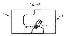
図1c及び1dは、係止システムが分解され得ることを示している。ロッド状スティック9を舌部用溝部3に側方から挿入する。可撓性舌部3は、押し返されて挿入溝部4に入り込み、第2パネル2を第1パネル1から解放することができる。
Figures 1c and 1d show that the locking system can be disassembled. The rod-
このような分解の主たる問題点は、ロッド状スティック9を正しい位置に入れて、且つ舌部用溝部5に正確に挿入しなければならないことである。ロッド状スティックが挿入溝部4に挿入された場合、分解は不可能である。
The main problem of such disassembly is that the rod-
本発明の実施形態の基本的な目的は、可撓性舌部により互いに直交して係止されたパネルの分解を単純化することである。 The basic purpose of an embodiment of the present invention is to simplify the disassembly of panels locked perpendicular to each other by flexible tongues.
本発明の実施形態の上記目的は、より強力でありながらより簡易な係止及び係止解除を提供する独立請求項による機械的係止システム及びパネルによって全体的に又は部分的に達成される。本発明の実施形態は、従属請求項から、そして発明の詳細な説明及び図面から明らかになる。 The above objects of the embodiments of the present invention are achieved in whole or in part by mechanical locking systems and panels according to the independent claims that provide stronger and simpler locking and unlocking. Embodiments of the invention will become apparent from the dependent claims and from the detailed description of the invention and the drawings.
本発明の第1態様は、第1パネルと第2パネルとを備えた一組のパネルである。第1パネルと第2パネルとの機械的連結を得るように、第2パネルのパネル縁部が第1パネルのコア溝部に挿入可能である。第1及び第2パネルが互いに本質的に直交して配設されているときの第1及び第2パネルの本質的に直線的な相対移動によって、パネル縁部はコア溝部に挿入可能である。パネル縁部は別箇の可撓性舌部を備えるとともにコア溝部は舌部用溝部を備えており、又は、パネル縁部は舌部用溝部を備えるとともにコア溝部は別箇の可撓性舌部を備えている。第1パネルの主面(MP−1)に対して直交する第1方向においてパネルを互いに連結するように、別箇の可撓性舌部は舌部用溝部に挿入可能である。第2パネルの主面(MP−2)に対して直交する第2方向においてパネルを互いに連結するように、第2パネルのパネル縁部は、第1パネルのコア溝と協働する(掛かり合う)ように構成されている。別箇の可撓性舌部の長手方向は、パネル縁部及び/又はコア溝部に対して平行に延在している。別箇の可撓性舌部は挿入溝部に配設されていて、第1及び第2パネルの係止中に、挿入溝部の底部に向かって内方に、そして舌部用溝部内へと外方に移動可能である。別箇の可撓性舌部は、ガイド突起を別箇の可撓性舌部の短縁に備え、ガイド突起は、第1及び第2パネルの係止及び/又は係止解除中に、その形状が変化するように構成されている。 A first aspect of the present invention is a set of panels including a first panel and a second panel. The panel edge of the second panel can be inserted into the core groove of the first panel so as to obtain a mechanical connection between the first panel and the second panel. The panel edges can be inserted into the core groove by the essentially linear relative movement of the first and second panels when the first and second panels are disposed essentially orthogonal to each other. The panel edge is provided with a separate flexible tongue and the core groove is provided with a tongue groove, or the panel edge is provided with a tongue groove and the core groove is a separate flexible tongue. Department. The separate flexible tongue can be inserted into the tongue groove so as to connect the panels to each other in a first direction orthogonal to the main surface (MP-1) of the first panel. The panel edges of the second panel cooperate with (engage with) the core groove of the first panel so as to connect the panels to each other in a second direction orthogonal to the main surface (MP-2) of the second panel. ) Is configured as follows. The longitudinal direction of the separate flexible tongue extends parallel to the panel edge and / or the core groove. A separate flexible tongue is disposed in the insertion groove and is outwardly directed toward the bottom of the insertion groove and into the tongue groove during locking of the first and second panels. It is possible to move towards. The separate flexible tongue is provided with a guide projection on the short edge of the separate flexible tongue, the guide projection being disengaged during the locking and / or unlocking of the first and second panels. It is comprised so that a shape may change.
本発明の概念により、パネルは改良された単純な態様で分解され得る。 Due to the inventive concept, the panel can be disassembled in an improved and simple manner.
好適には、一組のパネルにおけるパネルは、本質的に平行六面体として、より具体的には矩形平行六面体として形成される。 Preferably, the panels in a set of panels are formed essentially as parallelepipeds, more specifically as rectangular parallelepipeds.
各パネル、具体的には第1及び第2パネルは、下側面と上側面とを備え得る。好適には、下側面及び上側面は、矩形又は正方形として成形されるとともに平坦である。下側面及び上側面は、平行であり得る。一例において、パネルは均一な厚さを有している。別の例において、パネルは非均一な厚さを有している。更に別の例において、パネルは2つ以上の部分を有し、それぞれは均一な厚さを有している。パネルの下側面及び上側面は、パネルの主面に対して平行であり得る。特に、パネルの主面は、パネルの下側面又は上側面と一致し得る。更に、各パネルは、上側面と下側面とを連結し得る側縁を備え得る。平行六面体として形成されたパネルの場合、二対の側縁が存在するであろう。好適には、一対の側縁のそれぞれにおける少なくとも2つの側縁の一部同士が平行である。 Each panel, specifically the first and second panels, may comprise a lower side and an upper side. Preferably, the lower side and the upper side are shaped as a rectangle or square and are flat. The lower side and the upper side can be parallel. In one example, the panel has a uniform thickness. In another example, the panel has a non-uniform thickness. In yet another example, the panel has two or more portions, each having a uniform thickness. The lower side and the upper side of the panel may be parallel to the main surface of the panel. In particular, the main surface of the panel can coincide with the lower or upper surface of the panel. Further, each panel may include a side edge that can connect the upper side surface and the lower side surface. In the case of a panel formed as a parallelepiped, there will be two pairs of side edges. Preferably, a part of at least two side edges in each of the pair of side edges are parallel to each other.
一例において、パネルの密度は均一である。別の例において、パネルの密度は、パネルの中央部よりも上側面及び/又は下側面に近接した位置においてより高い。 In one example, the panel density is uniform. In another example, the density of the panel is higher at a location closer to the upper and / or lower side than the center of the panel.
第1方向は、第2パネルの主面に対して平行であり得る。更に、第2方向は、第1パネルの主面に対して平行であり得る。 The first direction may be parallel to the main surface of the second panel. Furthermore, the second direction may be parallel to the major surface of the first panel.
パネルのパネル縁部は、パネルの側縁の少なくとも一部を備え得る。また、パネル縁部は、側縁の近傍のパネルの下側面の一部及び上側面の一部を備え得る。パネル縁部の形状は、コア溝部の形状に実質的に一致し得る。したがって、第2パネルはしっかりとフィットした態様で第1パネルに係合し得る。特に、パネル縁部とコア溝部は、本質的にU字形状である。選択的に、パネル縁部及び/又はコア溝部の隅部は勾配を付けられ得る。 The panel edge of the panel may comprise at least a portion of the side edge of the panel. Further, the panel edge portion may include a part of the lower side surface and a part of the upper side surface of the panel in the vicinity of the side edge. The shape of the panel edge can substantially match the shape of the core groove. Thus, the second panel can engage the first panel in a tight fit manner. In particular, the panel edge and the core groove are essentially U-shaped. Optionally, the panel edges and / or the corners of the core grooves can be beveled.
ここで、別箇の可撓性舌部の短縁とは、別箇の可撓性舌部の長手方向における縁を意味している。 Here, the short edge of the separate flexible tongue means the edge in the longitudinal direction of the separate flexible tongue.
別箇の可撓性舌部は、ガイド突起として形成された外側縁部分を備え得る。 The separate flexible tongue may comprise an outer edge portion formed as a guide projection.
ガイド突起は、係止中に挿入溝部の内部に接触し得る。 The guide protrusion can contact the inside of the insertion groove during locking.
特に、第1及び第2パネルの係止状態において、ガイド突起は、挿入溝部の内部に接触し得る。 In particular, in the locked state of the first and second panels, the guide protrusion can contact the inside of the insertion groove.
或いは、第1及び第2パネルの係止状態において、挿入溝部の内部とガイド突起との間にはスペースが存在し得る。スペースは、好適には、挿入溝部の内部に向かう方向に沿った係止動作中の別箇の可撓性舌部の移動距離より小さい。 Alternatively, there may be a space between the inside of the insertion groove and the guide protrusion in the locked state of the first and second panels. The space is preferably smaller than the distance traveled by the separate flexible tongue during the locking operation along the direction towards the interior of the insertion groove.
ガイド突起は湾曲した形状であるとともに、ロッド形状工具が挿入溝部に挿入されると、このロッド形状工具を舌部用溝部内へガイドするように構成されている。ここで、湾曲した形状とは、ガイド突起の少なくとも一部が湾曲として成形されているということを意味している。湾曲は、非ゼロ曲率を有し得る。特に上面図から理解されるように、ガイド突起の外側面が、湾曲として成形され得る。曲率は、好適には、ガイド突起の外側面の接線方向と、ロッド形状工具の長手方向との間に形成される角度が鋭角であるようなものとされる。具体的には、この角度は1°乃至89°であり得る。ガイド突起は湾曲した形状であるため、ガイド突起の先端に向かう方向において、当該鋭角はガイド突起に沿って変化し得る。例えば、当該鋭角はガイド突起の先端に向かって拡大し得る。 The guide projection has a curved shape and is configured to guide the rod-shaped tool into the tongue groove when the rod-shaped tool is inserted into the insertion groove. Here, the curved shape means that at least a part of the guide protrusion is formed as a curve. The curvature may have a non-zero curvature. As can be seen in particular from the top view, the outer surface of the guide projection can be shaped as a curve. The curvature is preferably such that the angle formed between the tangential direction of the outer surface of the guide projection and the longitudinal direction of the rod-shaped tool is an acute angle. Specifically, this angle can be between 1 ° and 89 °. Since the guide protrusion has a curved shape, the acute angle can change along the guide protrusion in the direction toward the tip of the guide protrusion. For example, the acute angle can expand toward the tip of the guide protrusion.
別の実施形態によれば、ガイド突起は、少なくとも1つの直線部分を備えている。上面図から理解されるように、各直線部分は舌部の長手方向に対して傾斜し得る。一例において、ガイド突起は1つの直線部分を備えている。別の例において、ガイド突起は、少なくとも2つの直線部分を備えている。後者の例において、好適には、直線部分は並置されている。舌部の長手方向に対する角度は、異なる直線部分で異なっていてもよい。例えば、当該角度は、各直線部分によってガイド突起の先端に向かって拡大し得る。 According to another embodiment, the guide protrusion comprises at least one straight portion. As can be seen from the top view, each straight portion can be inclined with respect to the longitudinal direction of the tongue. In one example, the guide protrusion has one straight portion. In another example, the guide protrusion includes at least two straight portions. In the latter example, preferably the straight portions are juxtaposed. The angle of the tongue with respect to the longitudinal direction may be different in different linear portions. For example, the angle can be expanded toward the tip of the guide protrusion by each linear portion.
一例において、ガイド突起の先端に向かう方向に沿ったガイド突起の断面は一定である。別の例において、ガイド突起の断面はテーパしている。更に、非制限的な例において、先端に向かう方向に沿ったガイド突起の断面は、円形、楕円形、多角形、矩形、正方形、又は三角形として成形され得る。 In one example, the cross-section of the guide protrusion along the direction toward the tip of the guide protrusion is constant. In another example, the cross-section of the guide protrusion is tapered. Further, in a non-limiting example, the cross-section of the guide protrusion along the direction toward the tip can be shaped as a circle, ellipse, polygon, rectangle, square, or triangle.
ガイド突起は可撓性であり得る。より一般的には、ガイド突起の少なくとも一部が可撓性であり得る。 The guide protrusion can be flexible. More generally, at least a portion of the guide protrusion may be flexible.
ロッド形状工具は、本質的に丸い断面を備え得る。具体的には、当該断面は、円形又は楕円形として成形され得る。円形のような回転対称断面を有することにより、ロッド形状工具を溝に挿入する際のその適切な配向が重要でなくなるであろう。これにより、パネルの分解が更に簡単になるであろう。 The rod-shaped tool may have an essentially round cross section. Specifically, the cross section can be shaped as a circle or an ellipse. By having a rotationally symmetric cross-section such as a circle, its proper orientation when inserting the rod-shaped tool into the groove will not be important. This will further simplify panel disassembly.
別箇の可撓性舌部は、舌部の長さ方向に延在する複数の可撓性突起を備え得る。 The separate flexible tongue may comprise a plurality of flexible protrusions extending along the length of the tongue.
挿入溝部が、第1パネルのコア溝部に形成され得る。 An insertion groove may be formed in the core groove of the first panel.
パネル縁部が舌部用溝部を備えるとともにコア溝部が別箇の可撓性舌部を備えている場合、舌部用溝部は、第1パネルの下側面に又は上側面に配設され得る。具体的には、舌部用溝部は、第2パネルの下側面又は上側面において、第2パネルの側縁に近接して配設され得る。 If the panel edge comprises a tongue groove and the core groove comprises a separate flexible tongue, the tongue groove may be disposed on the lower side or upper side of the first panel. Specifically, the tongue groove portion may be disposed in proximity to the side edge of the second panel on the lower surface or upper surface of the second panel.
更に、パネル縁部が舌部用溝部を備えるとともにコア溝部が別箇の可撓性舌部を備えている場合、挿入溝部はコア溝部に形成され得る。コア溝部は、2つの側壁と底壁とを備え得る。コア溝部の2つの側壁は平行であり得る。一実施形態において、挿入溝部は、コア溝部の側壁に配設され得る。可撓性舌部の少なくとも一部の形状は、挿入溝部の形状に実質的に一致し得る。具体的には、可撓性舌部及び挿入溝部は、本質的にU字形状であり得る。挿入溝部は、2つの側壁と底壁とを備え得る。挿入溝部の側壁は平行であり得る。第1例において、挿入溝部の底壁は平坦である。第2例において、挿入溝部の底壁は丸みを帯びている。挿入溝部は、第1パネルの下側面及び/又は上側面に対して傾斜され得る。非制限的な例において、挿入溝部の側壁と第1パネルの下側面及び/又は上側面との間の角度は、5°乃至45°であり得る。 Further, when the panel edge portion includes a tongue groove portion and the core groove portion includes a separate flexible tongue portion, the insertion groove portion may be formed in the core groove portion. The core groove may include two side walls and a bottom wall. The two side walls of the core groove may be parallel. In one embodiment, the insertion groove may be disposed on the side wall of the core groove. The shape of at least a portion of the flexible tongue can substantially match the shape of the insertion groove. Specifically, the flexible tongue and the insertion groove can be essentially U-shaped. The insertion groove may include two side walls and a bottom wall. The sidewalls of the insertion groove can be parallel. In the first example, the bottom wall of the insertion groove is flat. In the second example, the bottom wall of the insertion groove is rounded. The insertion groove may be inclined with respect to the lower surface and / or the upper surface of the first panel. In a non-limiting example, the angle between the side wall of the insertion groove and the lower and / or upper side of the first panel can be 5 ° to 45 °.
舌部用溝部は、2つの側壁と底壁とを備え得る。舌部用溝部の側壁は平行であり得る。第1例において、舌部用溝部の底壁は平坦である。第2例において、舌部用溝部の底壁は丸みを帯びている。舌部用溝部は、第2パネルの下側面及び/又は上側面に対して傾斜され得る。非制限的な例において、舌部用溝部の側壁と第2パネルの下側面及び/又は上側面との間の角度は、45°乃至85°であり得る。舌部用溝部の傾斜は、挿入溝部の傾斜に一致し得る。これにより、第1及び第2パネルの連結状態において、舌部用溝部の平行な側壁と挿入溝部の平行な側壁は、本質的に互いに整列する。 The tongue groove may comprise two side walls and a bottom wall. The side walls of the tongue groove may be parallel. In the first example, the bottom wall of the tongue groove is flat. In the second example, the bottom wall of the tongue groove is rounded. The tongue groove may be inclined with respect to the lower surface and / or the upper surface of the second panel. In a non-limiting example, the angle between the side wall of the tongue groove and the lower and / or upper side of the second panel can be 45 ° to 85 °. The inclination of the tongue groove can coincide with the inclination of the insertion groove. Thereby, in the connected state of the first and second panels, the parallel side walls of the tongue groove and the parallel side walls of the insertion groove are essentially aligned with each other.
本発明の第2態様は、第1パネルと第2パネルとを備えたパネルの係止のための係止システムである。第1パネルと第2パネルとの機械的連結を得るように、第2パネルのパネル縁部が、第1パネルのコア溝部に挿入可能である。第1及び第2パネルが互いに本質的に直交して配設されているときの第1及び第2パネルの本質的に直線的な相対移動によって、パネル縁部はコア溝部に挿入可能である。係止システムは、コア溝部に形成された挿入溝部に配設された別箇の可撓性舌部と、パネル縁部にある舌部用溝部と、を備えている。舌部用溝部は、別箇の可撓性舌部の一部を収容するように適合されている。別箇の可撓性舌部は、ガイド突起を別箇の可撓性舌部の短縁に備えている。ガイド突起は、ロッド形状工具が舌部用溝部の少なくとも一部に挿入されると、その形状が変化するように構成されている。 A second aspect of the present invention is a locking system for locking a panel including a first panel and a second panel. The panel edge of the second panel can be inserted into the core groove of the first panel so as to obtain a mechanical connection between the first panel and the second panel. The panel edges can be inserted into the core groove by the essentially linear relative movement of the first and second panels when the first and second panels are disposed essentially orthogonal to each other. The locking system includes a separate flexible tongue disposed in the insertion groove formed in the core groove, and a tongue groove on the panel edge. The tongue groove is adapted to receive a portion of a separate flexible tongue. The separate flexible tongue comprises a guide projection on the short edge of the separate flexible tongue. The guide protrusion is configured to change its shape when the rod-shaped tool is inserted into at least a part of the tongue groove.
ロッド形状工具は、本質的に丸い断面を備え得る。 The rod-shaped tool may have an essentially round cross section.
本発明は、ロッド形状工具を、側方から、通常舌部用溝部よりも大きい挿入溝部に挿入すると、工具が自動的にガイド突起によって舌部用溝部にガイドされるという利点を提供する。ロッド形状工具は単純な丸い断面を有し得る。そして、溝部への挿入に際して工具を正確に配向しなくてよくなる。これにより、係止されたパネルの簡単且つ単純な分解が容易となる。 The present invention provides the advantage that when a rod-shaped tool is inserted from the side into an insertion groove that is usually larger than the tongue groove, the tool is automatically guided by the guide protrusion into the tongue groove. The rod-shaped tool can have a simple round cross section. And it becomes unnecessary to orient a tool correctly at the time of insertion in a groove part. This facilitates easy and simple disassembly of the locked panel.
本発明の第3態様によれば、第1パネルと第2パネルとを備えた一組のパネルが提供される。第1パネルと第2パネルとの機械的連結を得るように、第2パネルのパネル縁部が第1パネルのコア溝部に挿入可能であり、第1及び第2パネルが互いに本質的に直交して配設されているときの第1及び第2パネルの本質的に直線的な相対移動によって、パネル縁部はコア溝部に挿入可能である。更に、パネル縁部は別箇の可撓性舌部を備え、コア溝部は舌部用溝部を備えている。第1パネルの主面に直交する第1方向においてパネルを互いに連結するように、別箇の可撓性舌部は舌部用溝部に挿入可能である。第2パネルの主面に直交する第2方向においてパネルを互いに連結するように、第2パネルのパネル縁部は第1パネルのコア溝部と協働するように構成されている。別箇の可撓性舌部の長手方向は、パネル縁部及び/又はコア溝に対して平行に延在している。別箇の可撓性舌部は挿入溝部に配設されていて、第1及び第2パネルの係止中に、挿入溝部の底部に向かって内方に、そして前記舌部用溝部内へと外方に移動可能である。別箇の可撓性舌部を挿入溝部の底部に向かって内方に移動させつつ第1及び第2パネルを係止する際に、コア溝部の係合部が、別箇の可撓性舌部と係合するように配設されており、前記係合部は勾配を付けられている。 According to the third aspect of the present invention, a set of panels including a first panel and a second panel is provided. In order to obtain a mechanical connection between the first panel and the second panel, the panel edge of the second panel can be inserted into the core groove of the first panel, and the first and second panels are essentially orthogonal to each other. The panel edge can be inserted into the core groove by the essentially linear relative movement of the first and second panels when disposed. Further, the panel edge portion is provided with a separate flexible tongue portion, and the core groove portion is provided with a tongue groove portion. The separate flexible tongue can be inserted into the tongue groove so as to connect the panels to each other in a first direction orthogonal to the main surface of the first panel. The panel edge portion of the second panel is configured to cooperate with the core groove portion of the first panel so as to connect the panels to each other in a second direction orthogonal to the main surface of the second panel. The longitudinal direction of the separate flexible tongue extends parallel to the panel edge and / or the core groove. A separate flexible tongue is disposed in the insertion groove, inwardly toward the bottom of the insertion groove and into the tongue groove during locking of the first and second panels. It can move outward. When the first and second panels are locked while the separate flexible tongue is moved inward toward the bottom of the insertion groove, the engaging portion of the core groove is the separate flexible tongue. It is arrange | positioned so that it may engage with a part, The said engaging part is given the gradient.
勾配係合部は、第2パネルの上側面又は下側面に、又はその近傍に設けられた上方勾配係合部であり得る。 The gradient engaging portion may be an upward gradient engaging portion provided on or near the upper side or lower side of the second panel.
勾配係合部は、第1パネルの上部であって、第1パネルの中央部より高い密度を有する上部に設けられ得る。 The gradient engaging portion may be provided on an upper portion of the first panel and having a higher density than a central portion of the first panel.
勾配係合部は、コア溝部の側壁と第1パネルの下側面又は上側面との間に設けられ得る。具体的には、勾配係合部は、コア溝部の側壁と第1パネルの下側面又は上側面とを接合し得る。 The gradient engaging portion may be provided between the side wall of the core groove and the lower surface or the upper surface of the first panel. Specifically, the gradient engaging portion can join the side wall of the core groove and the lower surface or upper surface of the first panel.
第2パネルは、第1及び第2パネルの係止状態において勾配係合部と係合する重複部を備え得る。 The second panel may include an overlapping portion that engages with the gradient engaging portion in the locked state of the first and second panels.
第2パネルの厚さは、パネル縁部において、第2パネルの、第1及び第2パネルの係止状態において目に見える可視部より小さくてもよい。 The thickness of the second panel may be smaller at the panel edge than the visible portion of the second panel visible in the locked state of the first and second panels.
パネル縁部の下縁側面と平行上縁側面との間の距離が、下側面と平行上側面との間の距離より小さくてもよく、下縁側面及び上縁側面は、下側面及び上側面よりも第2パネルの側縁に近接して配置されている。 The distance between the lower edge side of the panel edge and the parallel upper edge side may be smaller than the distance between the lower side and the parallel upper side, and the lower edge side and the upper edge side are the lower side and the upper side. Rather than the side edge of the second panel.
挿入溝部は、パネル縁部の下縁側面に又は上縁側面に設けられ得る。或いは、挿入溝部は、第2パネルの下側面に又は上側面に設けられ得る。 The insertion groove may be provided on the lower edge side of the panel edge or on the upper edge side. Alternatively, the insertion groove may be provided on the lower surface or the upper surface of the second panel.
本発明の第4態様によれば、第1パネルと第2パネルとを備えた一組のパネルが提供される。第1パネルと第2パネルとの機械的連結を得るように、第2パネルのパネル縁部が第1パネルのコア溝部に挿入可能であり、第1及び第2パネルが本質的に同一平面MP−1に配設されているときの第1及び第2パネルの本質的に直線状の相対移動によってパネル縁部はコア縁部に挿入可能である。更に、パネル縁部は別箇の可撓性舌部を備えるとともにコア溝部は舌部用溝部を備えており、又は、パネル縁部は舌部用溝部を備えるとともにコア溝部が別箇の可撓性舌部を備えている。別箇の可撓性舌部は、第1パネルの主面に対して平行な第1方向においてパネルを互いに連結するために、舌部用溝部に挿入可能である。第2パネルの主面に直交する第2方向においてパネルを互いに連結するように、第2パネルのパネル縁部は第1パネルのコア溝部と協働するように構成されている。別箇の可撓性舌部の長手方向は、パネル縁部及び/又はコア溝に対して平行に延在している。更に、別箇の可撓性舌部は挿入溝部に配設されていて、第1及び第2パネルの係止中に、挿入溝部の底部に向かって内方に、そして舌部用溝部内へと外方に移動可能である。別箇の可撓性舌部は、ガイド突起を別箇の可撓性舌部の短縁に備えており、ガイド突起は、第1及び第2パネルの係止及び/又は係止解除中にその形状が変化するように構成されている。 According to the fourth aspect of the present invention, a set of panels including a first panel and a second panel is provided. To obtain a mechanical connection between the first panel and the second panel, the panel edge of the second panel can be inserted into the core groove of the first panel, and the first and second panels are essentially coplanar MP. The panel edge can be inserted into the core edge by the essentially linear relative movement of the first and second panels when disposed at -1. Further, the panel edge includes a separate flexible tongue and the core groove includes a tongue groove, or the panel edge includes a tongue groove and the core groove separate. Has a sexual tongue. A separate flexible tongue can be inserted into the tongue groove to connect the panels together in a first direction parallel to the major surface of the first panel. The panel edge portion of the second panel is configured to cooperate with the core groove portion of the first panel so as to connect the panels to each other in a second direction orthogonal to the main surface of the second panel. The longitudinal direction of the separate flexible tongue extends parallel to the panel edge and / or the core groove. In addition, a separate flexible tongue is disposed in the insertion groove, inwardly toward the bottom of the insertion groove and into the tongue groove during locking of the first and second panels. And move outwards. The separate flexible tongue is provided with a guide projection on the short edge of the separate flexible tongue, the guide projection during locking and / or unlocking of the first and second panels. The shape is configured to change.
ガイド突起は、更に、係止中に挿入溝部の内部に接触するように構成され得る。 The guide protrusion may be further configured to contact the inside of the insertion groove during locking.
ガイド突起は湾曲した形状であるとともに、ロッド形状工具が挿入溝部に挿入されると、ロッド形状工具を舌部用溝部内へガイドするように構成されている。 The guide protrusion has a curved shape and is configured to guide the rod-shaped tool into the tongue groove when the rod-shaped tool is inserted into the insertion groove.
ロッド形状工具は、本質的に丸い断面を備え得る。 The rod-shaped tool may have an essentially round cross section.
理解を容易にするために、図面中のいくつかの係止システムが概略的に示されている。好適な実施形態の組合せを用いて、より良い又は別の機能が達成されることが強調しておく。 For ease of understanding, several locking systems in the drawings are shown schematically. It is emphasized that better or different functions are achieved using a combination of preferred embodiments.
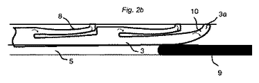
図2a乃至2dは、本実施形態により互いに連結された第1パネル1と第パネル2とを示す。第1パネル1は、この第1パネル1の上側面1bに配設されたコア溝部6を備えている。コア溝部6は、2つの対向する側壁6a、6bと、底壁6cとを備えている。対向する側壁6a、6bは平行である。第2パネル2は、パネル1、2の係止状態においてコア溝部6に配設されるパネル縁部12を備えている。より具体的には、第2パネルの下側面2aの一部、上側面2bの一部、及び側縁部2cが、コア溝部6に配設される。パネル1、2は、別箇の可撓性舌部3によって互いに係止され得る。
2a to 2d show a
図2aは、係止位置にある可撓性舌部3の上面図である。可撓性突起8を備えた可撓性舌部3の一部が、挿入溝部4に配置されている。公知技術によれば、対向する部分が舌部用溝5に配置されている。可撓性舌部3は外側縁部分3aを備えている。外側縁部分3aは、ロッド状工具9が挿入溝部4に側方から挿入されると自動的に工具9を舌部用溝部5にガイドするガイド突起10として形成されている。ガイド突起10は、舌部3の短縁に配設されている。対応するガイド突起10が、舌部3の他方の短縁(図示せず)に配設され得ることが理解される。
FIG. 2a is a top view of the
図2bは、舌部3が挿入溝4に押し込まれるようにロッド状工具9を側方から舌部3の長さ方向に対して平行に移動させているときに、可撓性のガイド突起が変形する様子を示している。係止中、及び舌部が挿入溝に押し込まれるときに、可撓性のガイド突起10が挿入溝4の内部に接触していれば有利である。ガイド突起10は好適には可撓性を有しており、且つ好適には湾曲した縁部分として形成されている。
FIG. 2 b shows that when the rod-shaped
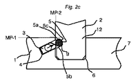
図2cは、係止システムの側面図である。本実施の形態によれば、第1パネル1の主面MP−1が、第1パネル1の上側面1bに一致している。更に、第2パネル2の主面MP−2が、図2cに示すように、左側に位置している第1パネル2の下側面2aに一致している。ロッド状工具9は、好適には、本質的に丸い断面を有している。本実施形態によれば、ロッド状工具9の断面は円形である。更に、ロッド状工具9の幅は、2つの平行な側壁5a、5bの間における舌部用溝部5の幅に一致している。本実施形態によれば、2つの側壁を連結する舌部用溝部5の底壁5cは丸みを帯びている。丸みを帯びた底壁5cの曲率は、ロッド状工具9の曲率に実質的に一致している。したがって、ロッド状工具9に対する良好なガイド動作が提供され得る。本実施形態において、ロッド状工具9は、舌部用溝部5の内部に嵌合するように適合されており、これにより、ロッド状工具9の本質的にいずれの部分も第2パネル2の下側面2aの外部に延出しない。したがって、パネル1、2は簡単に分解され得る。なぜならば、舌部3が挿入溝4へと移動する際にロッド状工具9は舌部用溝部5の内部に嵌合し得るからであり、これにより第1パネル及び第2パネル2との機械的連結が解放される。図2dは、本実施形態による第1パネル1と第2パネル2との分解を示している。
FIG. 2c is a side view of the locking system. According to the present embodiment, the main surface MP-1 of the
ロッド状工具9及び舌部用溝部5の他の形状が同様に想定され得ることが、明らかである。例えば、ロッド状工具9の断面は、多角形、矩形、正方形、楕円形、三角形又は星形として成形されてもよい。また、他の実施形態によれば、底壁はロッド状工具9の形状に一致していなくてもよい。例えば、ロッド状工具9の断面は円形であってもよく、舌部用溝部5の断面は、例えば平面的な底壁を備えたU字形状であってもよい。
It is clear that other shapes of the rod-shaped
また、挿入溝部4は第2パネル2に形成され得るとともに、舌部用溝部5は第1パネル1のコア溝6に形成され得る。これについて以下により詳細に説明する。
In addition, the
上述の実施形態は、工具9の挿入が、挿入溝4及び舌部用溝5を含む全体的な断面において実施されるという利点を提供する。対称的な断面の利用により、溝への挿入前に工具9を正確に配向しなくてもよくなる。
The embodiment described above offers the advantage that the insertion of the
ロッド状工具9のガイド動作が図2a及び2cに示されている。破線が、ロッド状工具9の挿入溝4への挿入時の位置を示し、矢印がロッド状ツール9が舌部用溝部5内へと図示の方向においてガイドされる様子を示している。
The guide action of the rod-shaped
図3aは、いくつかの射出成形された熱可塑性の可撓性舌部3を備えた舌部ブランク11を示している。舌部は、好適には、ブランク11から、内側に配置されるとともに舌部3の外側縁部から距離を置いた離間部Sにおいて離間している。
FIG. 3 a shows a tongue blank 11 with several injection-molded thermoplastic
図3bは、ガイド突起10を可撓性突起8のうちの1つに代え得ることを示している。これにより、全ての可撓性突起8が舌部に沿って舌部の長さ方向に配置されるとともに、ガイド突起10から長さ方向において離間している。
FIG. 3 b shows that the
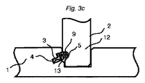
図3cは、他のタイプの舌部、例えば外側部分にスナップタブ13を備えた可撓性舌部が使用される場合にも本発明の原理を利用して分解を改善し得ることを示している。可撓性のスナップタブ13を備えた係止システムは、本質的に丸い断面を有する工具9を使用して第1パネルと第2パネルとを解放するように形成され得る。
FIG. 3c shows that other types of tongues, such as flexible tongues with
図3dは、スナップタブ13を備えた舌部3が、内側部分において対称的な断面と、楔状縁部分14となるように切断又は形成され得る縁部分とを備え得ることを示している。可撓性舌部は、可撓性のスナップタブと、その長さ方向に沿った非対称的な断面とを備え得る。
FIG. 3 d shows that the
特に、可撓性舌部3は、可撓性舌部3の縁部に向かって長手方向にテーパ状となっていてもよい。したがって、可撓性舌部3の断面積は、縁部に向かって減少してもよい。また、断面の内側部分から断面の外側部分に至る最大水平距離は、縁部に向かって減少していてもよい。ここで、水平距離は、可撓性舌部3が接触且つ伸張するように適合された方向において測定される。例えば、水平距離は、可撓性のスナップタブ13が接触且つ伸張するように適合された方向において測定され得る。図3dによる実施形態に示すように、可撓性スナップタブ13の断面は、縁部に向かって減少している。可撓性スナップタブ13の一部分13aが、テーパした縁部を提供するように可撓性舌部3から切り欠かれている。
In particular, the
次に、図4a乃至4cを参照して別の実施形態を説明する。図4a及び4bは、組立て中の第1パネル1及び第2パネル2の側面図である。図4a乃至4cにおいて、第1パネル1は水平方向に延在し、第2パネル2は鉛直方向に延在していることが理解され、第1パネル1と第2パネルとの連結領域のみが示されている。第1パネル1及び第2パネル2は、本質的に互いに直交するように配設されている。
Next, another embodiment will be described with reference to FIGS. 4a to 4c. 4a and 4b are side views of the
本実施形態によれば、第1パネル1は、上部30、中央部32及び下部34の3つの部分を備えている。上部30及び下部34は、上側面1b及び下側面1aにそれぞれ近接して配置され、中央部32より高い密度を有している。
According to the present embodiment, the
コア溝部6は、2つの対向する側壁6a、6b、及び底壁6cを備えている。コア溝部6は、舌部用溝部5を備えている。舌部用溝部5は、舌部用溝部5の側壁6aに設けられている。したがって、舌部用溝部5は、コア溝部6の左側に配置された、第1パネル1の左側部21aに設けられている。更に、舌部用溝部5は、2つの平行な側壁5a、5b、及び底壁5cを備えている。図4a乃至4cの側面図から理解されるように、下側壁5aの延長直線Eが、コア溝部6の右側に配置された、第1パネル1の右側部21bにおいて又はその上方に位置している。したがって、切断工具等の工具により、工具を直線状に移動させることによって簡単に舌部用溝部5が設けられ得る。
The
コア溝部6の係合部20は勾配を付けられている。勾配係合部20は、側壁6aの上部と第1パネル1の上側面1bとの間に設けられて、これらを接合している。或いは、コア溝部6の係合部20は、丸みを付けられていてもよい。
The engaging
更に、第2パネル2のパネル縁部12は、パネル2の内側部よりも小さい厚さを有している。ここで、内側部とは、パネル縁部12よりも第2パネル2の側縁2cから離れた位置にある。より具体的には、パネル縁部12は、下縁側面22aと上縁側面22bとを備えている。下縁側面22aと上縁側面22bとは、互いに平行であるとともに、第2パネル2の下側面2a及び上側面2bよりも、第2パネルの側縁2cに近接している。図4cに示すように、下縁側面22aと上縁側面22bとの間の距離d1は、下側面2aと上側面2bとの間の距離d2より小さい。
Furthermore, the
下縁側面22aは、重複部24により下側面2aに接合されている。本実施形態によれば、重複部25により第2パネル2の上側面2bに接合された対応する上縁側面22bが存在している。コア溝部6の勾配係合部20と勾配面27とにそれぞれ係合した第1パネルと第2パネル2の、組立てられた状態にある又は係止位置にある重複部24、25により、パネル縁部12及び/又はコア溝部6を、より目に見えないようにすることができる。
The lower edge side surface 22 a is joined to the
パネル縁部12は、別箇の可撓性舌部3を備えている。別箇の可撓性舌部3は、収縮状態と伸張状態とをとり得るとともに、力が作用していない場合には伸長状態をとる性質を有している。別箇の可撓性舌部3は、パネル縁部12の下縁側面22aに設けられた挿入溝部4に配設されている。別箇の可撓性舌部3は、面取部23を備えている。別箇の可撓性舌部3が挿入溝部4に挿入されるとき、面取部23は下方を向いている。
The
第1パネル1と第2パネルとを組立てる場合、第1パネルと第2パネルとの相対的な鉛直方向移動により、第2パネル2のパネル縁部12を第1パネル1のコア溝部6に挿入する。移動は直線的である。別箇の可撓性舌部3は、挿入溝部4に部分的に挿入されているが、鉛直方向移動中に面取部23が勾配係合部20に係合すると挿入溝部4の内部へ更に移動する。勾配係合部20により、面取部23は組立に際して平滑な表面と係合する。したがって、面取部23が組立中に尖った縁部に係合することが回避され得る。更に挿入溝部4の内部へと移動すると、別箇の可撓性舌部3は収縮状態となる。挿入溝部4の側壁4a、4bが舌部用溝部5の側璧5a、5bと整列すると、別箇の可撓性舌部3は伸長して挿入溝部4から出て舌部用溝部5に入るように移動して、これにより、第1パネルの主面MP−1に直交する方向における第1パネル1及び第2パネル2の係止が得られる。
When the
コア溝部6は、側壁6aと底壁6cとの間、及び側壁6bと底壁6cとの間に傾斜部16を備えている。更に、パネル縁部12は、下縁側面22aと第2パネル2の側縁2cとの間の勾配部26と、上縁側面22bと第2パネルの側縁2cとの間の勾配部26と、を備えている。傾斜部16の形状は、勾配部26の形状と実質的に一致していてもよい。例えば、傾斜部16と勾配部26の傾斜は実質的に同じである。勾配部26は、縁側面22a、22bと側縁2cとの間の尖った隅部を除去し得る。また、勾配部26は、第2パネル2を適切な係止位置へとガイドし得る。
The
パネル1、2の係止状態において、第2パネル2の主面MP−2に直交する方向である第2方向においてパネル同士を互いに連結するように、パネル縁部12はコア溝部6と協働する。
In the locked state of the
図4bから、第1パネルと第2パネル2の係止状態において、第1パネル1及び第2パネル2の目に見える外側部分が均一な厚さを有していることが明らかである。
From FIG. 4b, it is clear that the visible outer portions of the
別の実施形態によれば、第2パネル2は均一な厚さを有し得ることが理解される。
It will be appreciated that according to another embodiment, the
図4cは、分解中の第1パネル1と第2パネル2の側面図である。これは、図2a乃至2dについて説明した分解方法と類似している。特に、分解に際して、ロッド形状工具9が側方から挿入溝部4に挿入されて、別箇の可撓性舌部3の短縁に設けられたガイド突起10によって舌部用溝部5の適切な位置へとガイドされる。ロッド形状工具9が舌部用溝部5に挿入されると、別箇の可撓性舌部3は挿入溝部4内へと移動する。したがって、パネル2は係止解除されて、パネル縁部12は、第1パネル1と第2パネル2の相対的な直線鉛直方向移動によってコア溝部6から取り外され得る。
FIG. 4c is a side view of the
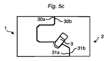
図5a乃至5dは、係止状態において同一の主面MP−1に配置される第1パネルと第1パネル2との係止及び係止解除に使用され得る係止システムを示している。換言すれば、パネルは、互いに本質的に平行に配設される。このような係止システムは、例えば0.6mの長さを有し、係止後に例えば1.2又は1.8mの長さを有する本棚の部品を形成するような、2つ又は複数個の家具部品を係止するために使用され得る。このようなタイプの係止システムを提供する利点は、小型の部品は輸送や組立及び分解が容易であるということである。他の長さを有する家具部品が想定され得ることが明らかである。非制限的な例において、長さは、0.1m乃至1.0mである。
5a to 5d show a locking system that can be used for locking and unlocking the
本実施形態において、第1パネル1と第2パネルは同一の厚さを有している。
In the present embodiment, the
第1パネル1はコア溝6と舌部用溝部5とを備え、第2パネル2はパネル縁部12を備えている。パネル縁部12は、第1及び第2パネルの主面MP−1に平行な移動によってコア溝部6に挿入可能である。パネル縁部12は、挿入溝部4に設けられた別箇の可撓性舌部3を備えている。パネルの係止状態において、別箇の可撓性舌部3は、舌部用溝部5内に係止する。
The
別の実施形態(図示せず)によれば、舌部用溝部5が第2パネル2に設けられ得るとともに、別箇の可撓性舌部3が第1パネル1に設けられ得る。
According to another embodiment (not shown), the
係止された部品の十分な剛性を提供するために、係止システムは強固でなくてはならない。好適には、パネル1、2が係止されたとき、第1パネル1の上縁30a及び下縁31aと、第2パネル2の上縁31b及び下縁31bが互いに接触する。
In order to provide sufficient rigidity of the locked part, the locking system must be strong. Preferably, when the
本実施形態によれば、第1及び第2パネルの係止状態において、パネル縁部12の側面がコア溝部6の底壁に係合する。これは図5cにおいて理解され得る。また、係止状態において、パネル縁部12の上面及び下面が、コア溝部6の2つの対向する側壁のそれぞれと係合する。しかしながら別の実施形態(図示せず)によれば、第1及び第2パネルの係止状態において、パネル縁部12の側面はコア溝部6の底壁から離間していてもよい。
According to this embodiment, the side surface of the
第1パネル1は、係合部40を備えている。別箇の可撓性舌部3を挿入溝部4の底部に向けて内側に移動させつつ第1及び第2パネルを係止する際に、係合部40は別箇の可撓性舌部3に係合するように配設されている。係合部40は、第1及び第2パネルの主面MP−1に対して傾斜している。更に、係合部40は、舌部用溝部5に隣接する部分42において勾配を付けられている。
The
図5dは、上述の方法による、ロッド形状工具9を用いた第1及び第2パネルの係止解除を示している。別箇の可撓性舌部3は、ガイド突起10として形成された外縁部3aを備えている。工具9が側方から挿入溝部4に挿入されると、ガイド突起10は自動的にロッド形状工具9を舌部用溝部5内へガイドする。
FIG. 5d shows the unlocking of the first and second panels using the rod-shaped
Claims (15)
前記パネル縁部(12)は別箇の可撓性舌部(3)を備えるとともに、前記コア溝部(6)は舌部用溝部(5)を備えており、
前記第1パネルの上側面(1b)に対応する前記第1パネルの主面(MP−1)に対して直交する第1方向においてパネルを互いに連結するように、前記別箇の可撓性舌部(3)は前記舌部用溝部(5)に挿入可能であり、
前記第2パネルの下側面(2a)に対応する前記第2パネルの主面(MP−2)に対して直交する第2方向において前記パネルを互いに連結するように、前記第2パネル(2)の前記パネル縁部(12)は、前記第1パネル(1)の前記コア溝部(6)に挿入されるように構成されており、
前記別箇の可撓性舌部(3)の長手方向は、前記パネル縁部(12)及び/又はコア溝部(6)に対して平行に延在しており、
前記別箇の可撓性舌部(3)は挿入溝部(4)に配設されていて、前記第1及び第2パネルの係止中に、前記挿入溝部(4)の底部に向かって内方に、そして前記舌部用溝部(5)内へと外方に移動可能であり、
前記別箇の可撓性舌部(3)を前記挿入溝部(4)の底部に向かって内方に移動させつつ前記第1及び第2パネルを係止する際に、前記コア溝部(6)の係合部(20)が、前記別箇の可撓性舌部(3)と係合するように配設されており、前記係合部(20)は勾配を付けられているか、又は、丸められている、
ことを特徴とする一組のパネル。 A set of panels (1, 2), which is a furniture component comprising a first panel (1) and a second panel (2) formed as a rectangle or a square , wherein the first panel and the second panel The panel edge (12) of the second panel (2) can be inserted into the core groove (6) of the first panel (1) so as to obtain a mechanical connection with the first and second panels. The panel edge (12) can be inserted into the core groove (6) by the essentially linear relative movement of the first and second panels when they are arranged essentially orthogonal to each other. A set of panels,
The panel edge (12) includes a separate flexible tongue (3), and the core groove (6) includes a tongue groove (5),
The separate flexible tongue so as to connect the panels to each other in a first direction orthogonal to the main surface (MP-1) of the first panel corresponding to the upper side surface (1b) of the first panel. The part (3) can be inserted into the tongue groove (5),
The second panel (2) so as to connect the panels to each other in a second direction orthogonal to the main surface (MP-2) of the second panel corresponding to the lower surface (2a) of the second panel. the panel edge (12) is configured to be inserted into the core grooves (6) of said first panel (1),
The longitudinal direction of the separate flexible tongue (3) extends parallel to the panel edge (12) and / or the core groove (6),
The separate flexible tongue (3) is disposed in the insertion groove (4) and is moved toward the bottom of the insertion groove (4) during the locking of the first and second panels. And outwardly into the tongue groove (5),
When the separate flexible tongue (3) is moved inward toward the bottom of the insertion groove (4) and the first and second panels are locked, the core groove (6) The engagement portion (20) is arranged to engage the separate flexible tongue (3), and the engagement portion (20) is beveled, or Rounded,
A set of panels characterized by that.
請求項1に記載の一組のパネル。 The engaging part (20) is provided on the upper part (30) of the first panel (1), and the upper part (30) has a higher density than the central part (32) of the first panel (1). is doing,
A set of panels according to claim 1.
請求項1又は2に記載の一組のパネル。 The engaging portion (20) is provided between a side wall (6a) of the core groove portion (6) and a lower side surface (1a) or an upper side surface (1b) of the first panel (1).
A set of panels according to claim 1 or 2.
ことを特徴とする請求項1乃至3のいずれかに記載の一組のパネル。 The second panel (2) has an overlapping portion (24) configured to engage with the engaging portion (20) when the first panel (1) and the second panel (2) are locked. Have
A set of panels according to any one of claims 1 to 3.
ことを特徴とする請求項4に記載の一組のパネル。 The second panel (2) engages with a gradient portion (27) provided on the first panel (1) in a locked state of the first panel (1) and the second panel (2). Further having an overlapping portion (25) configured in
A set of panels as claimed in claim 4.
請求項1乃至5のいずれかに記載の一組のパネル。 The thickness of the panel edge (12) of the second panel (2) located inside the core groove (6) in the locked state of the first panel (1) and the second panel (2). Is smaller than the visible portion located outside the core groove (6) in the locked state of the first panel (1) and the second panel (2) of the second panel (2).
A set of panels according to any of claims 1-5.
請求項1乃至6のいずれかに記載の一組のパネル。 The distance between the lower edge side surface (22a) of the panel edge (12) and the parallel upper edge side surface (22b) is smaller than the distance between the lower side surface (2a) and the parallel upper side surface (2b), The lower edge side surface (22a) and the upper edge side surface (22b) are disposed closer to the side edge (2c) of the second panel (2) than the lower side surface (2a) and the upper side surface (2b). ing,
A set of panels according to any of claims 1-6.
請求項7に記載の一組のパネル。 The insertion groove (4) is provided on the lower edge side (22a) of the panel edge (12) or on the upper edge side (22b).
A set of panels according to claim 7.
請求項1乃至8のいずれかに記載の一組のパネル。 The tongue groove (5) is provided on the side wall (6a) of the core groove (6).
A set of panels according to any of claims 1-8.
請求項9に記載の一組のパネル。 The tongue groove (5) is provided on one side (21a) of the first panel (1) disposed on one side of the core groove (6), and the tongue groove (5). Has two parallel side wall portions (5a, 5b) and a bottom wall (5c), and the extended straight line (E) of the lower side wall portion (5b) is the other of the core groove portion (6). Arranged on the other side (21b) of the first panel (1) or above it,
A set of panels according to claim 9.
前記別箇の可撓性舌部(3)はさらに、前記挿入溝部(4)に部分的に挿入され、且つ、本質的に直線的な相対移動中に、前記面取部(23)が前記係合部(20)に係合すると、前記挿入溝部(4)の内部へ移動するように構成されている、
請求項1乃至10のいずれかに記載の一組のパネル。 Flexible tongues of the Bekko (3), when the flexible tongue of the Bekko (3) is inserted into the insertion groove (4), configured to face downward chamfered Part (23),
The separate flexible tongue (3) is further partially inserted into the insertion groove (4), and the chamfer (23) is inserted into the chamfer (23) during an essentially linear relative movement. When engaged with the engaging portion (20), it is configured to move into the insertion groove (4).
A set of panels according to any one of the preceding claims.
請求項1乃至11のいずれかに記載の一組のパネル。 The core groove part (6) has an inclined part (16) between the side wall (6a) and the bottom wall (6c) and between the side wall (6b) and the bottom wall (6c). ,
A set of panels according to any of the preceding claims.
請求項12に記載の一組のパネル。 The panel edge portion (12) includes a slope portion (26) between a lower edge side surface (22a) and a side edge (2c) of the second panel (2), an upper edge side surface (22b), and the second edge. A slope (26) between the side edges (2c) of the panel (2),
A set of panels according to claim 12.
請求項1乃至13のいずれかに記載の一組のパネル。 When the side wall (4a, 4b) of the insertion groove (4) is aligned with the side wall (5a, 5b) of the groove (5) for the tongue, the separate flexible tongue (3) is In order to obtain a locking state of the first panel (1) and the second panel (2) in a direction perpendicular to the main surface (MP-1) of the first panel (1), the extension and the insertion groove Configured to move from (4) to the tongue groove (5).
A set of panels according to any of the preceding claims.
請求項1乃至14のいずれかに記載の一組のパネル。 The separate flexible tongue (3) has a guide protrusion (10) on a short edge of the separate flexible tongue (3), and the guide protrusion (10) is the first protrusion. The guide projection (10) has a curved shape, and the rod-shaped tool (9) is configured to change in shape while the panel and the second panel are locked and / or released. The set according to any one of claims 1 to 14, wherein the rod-shaped tool (9) is configured to guide into the tongue groove (5) when inserted into the insertion groove (4). Panel.
Applications Claiming Priority (3)
| Application Number | Priority Date | Filing Date | Title |
|---|---|---|---|
| SE1400231-5 | 2014-05-09 | ||
| SE1400231 | 2014-05-09 | ||
| PCT/SE2015/050518 WO2015171068A1 (en) | 2014-05-09 | 2015-05-08 | Mechanical locking system for building panels |
Publications (3)
| Publication Number | Publication Date |
|---|---|
| JP2017519950A JP2017519950A (en) | 2017-07-20 |
| JP2017519950A5 JP2017519950A5 (en) | 2018-05-31 |
| JP6605501B2 true JP6605501B2 (en) | 2019-11-13 |
Family
ID=54392762
Family Applications (1)
| Application Number | Title | Priority Date | Filing Date |
|---|---|---|---|
| JP2016566266A Active JP6605501B2 (en) | 2014-05-09 | 2015-05-08 | Mechanical locking system for building material panels |
Country Status (15)
| Country | Link |
|---|---|
| US (3) | US10876562B2 (en) |
| EP (2) | EP3140555B1 (en) |
| JP (1) | JP6605501B2 (en) |
| KR (1) | KR102475315B1 (en) |
| CN (2) | CN111237308B (en) |
| BR (1) | BR112016025783B1 (en) |
| CA (1) | CA2946997C (en) |
| EA (1) | EA037707B1 (en) |
| ES (1) | ES2873499T3 (en) |
| MX (1) | MX2016014501A (en) |
| MY (1) | MY181141A (en) |
| PL (1) | PL3140555T3 (en) |
| SG (1) | SG11201608909VA (en) |
| UA (1) | UA123304C2 (en) |
| WO (1) | WO2015171068A1 (en) |
Families Citing this family (52)
| Publication number | Priority date | Publication date | Assignee | Title |
|---|---|---|---|---|
| US8061104B2 (en) | 2005-05-20 | 2011-11-22 | Valinge Innovation Ab | Mechanical locking system for floor panels |
| BE1019891A5 (en) | 2011-03-28 | 2013-02-05 | Unilin Bvba | COMPOSITIONED ELEMENT AND BACK WALL CONSTRUCTION APPLIED HEREIN. |
| UA109938C2 (en) | 2011-05-06 | 2015-10-26 | MECHANICAL LOCKING SYSTEM FOR CONSTRUCTION PANELS | |
| EP4166731A1 (en) | 2013-06-27 | 2023-04-19 | Välinge Innovation AB | Building panel with a mechanical locking system |
| US9726210B2 (en) | 2013-09-16 | 2017-08-08 | Valinge Innovation Ab | Assembled product and a method of assembling the product |
| CN105518316B (en) | 2013-09-16 | 2019-03-29 | 瓦林格创新股份有限公司 | Combination product and the method for assembling the combination product |
| US10830268B2 (en) | 2014-01-10 | 2020-11-10 | Valinge Innovation Ab | Furniture panel |
| US9714672B2 (en) | 2014-01-10 | 2017-07-25 | Valinge Innovation Ab | Panels comprising a mechanical locking device and an assembled product comprising the panels |
| SG11201608909VA (en) | 2014-05-09 | 2016-11-29 | Vaelinge Innovation Ab | Mechanical locking system for building panels |
| MY179064A (en) | 2014-07-11 | 2020-10-27 | Valinge Innovation Ab | Panel with a slider |
| CN107002411B (en) | 2014-11-27 | 2020-06-16 | 瓦林格创新股份有限公司 | Mechanical locking system for floor panels |
| US9655442B2 (en) | 2014-12-19 | 2017-05-23 | Valinge Innovation Ab | Panels comprising a mechanical locking device and an assembled product comprising the panels |
| EP3285620A4 (en) | 2015-04-21 | 2018-11-14 | Välinge Innovation AB | Panel with a slider |
| EP3288422B1 (en) | 2015-04-30 | 2020-02-26 | Välinge Innovation AB | Panel with a fastening device |
| PL3353429T3 (en) | 2015-09-22 | 2024-04-29 | Välinge Innovation AB | Set of panels comprising a mechanical locking device and method for dis-assembling said panels |
| KR20180090838A (en) | 2015-12-03 | 2018-08-13 | 뵈린게 이노베이션 에이비이 | Panels comprising mechanical locks and assembled products containing such panels |
| WO2017131574A1 (en) | 2016-01-26 | 2017-08-03 | Välinge Innovation AB | Panels comprising a mechanical locking device and an assembled product comprising the panels |
| BR112018014377A2 (en) | 2016-02-04 | 2018-12-18 | Välinge Innovation AB | panel set for an assembled product |
| CA3011703A1 (en) | 2016-02-09 | 2017-08-17 | Valinge Innovation Ab | Element and method for providing dismantling groove |
| UA124383C2 (en) | 2016-02-09 | 2021-09-08 | Велінге Інновейшн Аб | A set of three panel-shaped elements |
| HUE053138T2 (en) | 2016-02-15 | 2021-06-28 | Vaelinge Innovation Ab | A method for forming a panel for a furniture product |
| FR3054419B1 (en) * | 2016-07-26 | 2018-12-07 | Inovame | FURNITURE BOX |
| CA3040653A1 (en) | 2016-10-27 | 2018-05-03 | Valinge Innovation Ab | Set of panels with a mechanical locking device |
| JP7201617B2 (en) | 2017-05-15 | 2023-01-10 | ベーリンゲ、イノベイション、アクチボラグ | Elements and locking devices for assemblies |
| CN108029674A (en) * | 2017-12-06 | 2018-05-15 | 珠海格力电器股份有限公司 | Rat-proof baffle structure and air conditioner |
| PL3728870T3 (en) | 2017-12-22 | 2023-08-21 | Välinge Innovation AB | A set of panels |
| CN111465773B (en) | 2017-12-22 | 2021-11-02 | 瓦林格创新股份有限公司 | Panel set, method for assembling the panel set and locking device for furniture products |
| NO20172047A1 (en) * | 2017-12-24 | 2019-06-25 | Humeneq As | The invention relates to a click arrangement for countertop and other plate joints. |
| PL3768981T3 (en) | 2018-03-23 | 2024-01-22 | Välinge Innovation AB | Set of panels |
| EA202092389A1 (en) * | 2018-04-18 | 2021-01-27 | Велинге Инновейшн Аб | PANEL KIT WITH MECHANICAL LOCKING DEVICE |
| CN112119226B (en) * | 2018-04-18 | 2022-05-27 | 瓦林格创新股份有限公司 | Panel set with mechanical locking device |
| EP3781824B1 (en) * | 2018-04-18 | 2024-04-10 | Välinge Innovation AB | Set of panels with a mechanical locking device |
| KR20200141076A (en) * | 2018-04-18 | 2020-12-17 | 뵈린게 이노베이션 에이비이 | Symmetrical tongue and tea-cross |
| US11614114B2 (en) | 2018-04-19 | 2023-03-28 | Valinge Innovation Ab | Panels for an assembled product |
| US11497303B2 (en) * | 2018-05-04 | 2022-11-15 | Poppin Inc. | Toolless attachment assembly |
| EA202190506A1 (en) | 2018-08-30 | 2021-07-30 | Велинге Инновейшн Аб | PANEL SET WITH MECHANICAL LOCKING DEVICE |
| MX2021008215A (en) * | 2019-01-10 | 2021-08-11 | Vaelinge Innovation Ab | Set of panels that can be vertically unlocked, a method and a device therefore. |
| EP3834661A1 (en) | 2019-12-11 | 2021-06-16 | Välinge Innovation AB | Mechanical locking system for panels |
| JP2023507075A (en) | 2019-12-19 | 2023-02-21 | ベーリンゲ、イノベイション、アクチボラグ | A set of panels with mechanical locking devices |
| KR20220130156A (en) | 2020-01-22 | 2022-09-26 | 뵈린게 이노베이션 에이비이 | set of panels with mechanical locking device |
| EP3871560A1 (en) | 2020-02-26 | 2021-09-01 | Välinge Innovation AB | Set of panels with a mechanical locking device |
| EP3871559A1 (en) | 2020-02-26 | 2021-09-01 | Välinge Innovation AB | Set of panels with a mechanical locking device |
| US11702844B2 (en) | 2020-06-05 | 2023-07-18 | Valinge Innovation Ab | Building panels comprising a locking device |
| CN115867171A (en) * | 2020-07-17 | 2023-03-28 | 瓦林格创新股份有限公司 | Mechanical locking system for panels |
| CN112223744A (en) * | 2020-09-30 | 2021-01-15 | 深圳市创想三维科技有限公司 | Simple device platform and 3D printer with same |
| US11680595B2 (en) | 2020-12-11 | 2023-06-20 | Valinge Innovation Ab | Rail for cabinets |
| WO2022150002A1 (en) | 2021-01-07 | 2022-07-14 | Välinge Innovation AB | Wedge-shaped tongue insertion groove |
| WO2022159013A1 (en) | 2021-01-19 | 2022-07-28 | Välinge Innovation AB | A set of panels, a method for assembly of the same and a locking device for a furniture product |
| CA3206480A1 (en) | 2021-02-03 | 2022-08-11 | Valinge Innovation Ab | Building panels comprising a locking device |
| US12018707B2 (en) | 2021-03-01 | 2024-06-25 | Välinge Innovation AB | Mechanical connection arrangement for panels |
| CN116981818A (en) * | 2021-03-19 | 2023-10-31 | 瓦林格创新股份有限公司 | Building panel with mechanical locking system |
| EP4413272A1 (en) * | 2021-10-04 | 2024-08-14 | Välinge Innovation AB | Mechanical connection arrangement for panels |
Family Cites Families (332)
| Publication number | Priority date | Publication date | Assignee | Title |
|---|---|---|---|---|
| DE228872C (en) | ||||
| US291032A (en) | 1884-01-01 | Isaac g- | ||
| US634581A (en) | 1898-11-21 | 1899-10-10 | Robert H Miller | Carpenter's square. |
| US701000A (en) | 1901-07-31 | 1902-05-27 | Carl F W Ahrens | File-cabinet. |
| US861911A (en) | 1905-11-04 | 1907-07-30 | William Stewart | Joint for articles of furniture or woodwork. |
| US881673A (en) | 1907-03-11 | 1908-03-10 | Arthur L Ellison | Wardrobe or safe. |
| US1534468A (en) | 1922-10-30 | 1925-04-21 | Jr John J Shea | Joint structure |
| US1533099A (en) | 1924-07-14 | 1925-04-14 | Robert E Carroll | Square-corner glue joint |
| GB245332A (en) | 1925-05-04 | 1926-01-07 | George Hugh Foster | An improved dowelled joint for woodwork and the like |
| US1800386A (en) | 1926-08-28 | 1931-04-14 | Andrew Hoffman Mfg Company | Display rail |
| US1800387A (en) | 1926-12-30 | 1931-04-14 | Andrew Hoffman Mfg Company | Article-supporting device |
| US1802245A (en) | 1930-08-26 | 1931-04-21 | Clarence L Foretich | Display stand and shelving |
| US1954242A (en) | 1932-07-28 | 1934-04-10 | Thomas E Heppenstall | Dovetail spring joint |
| US2360451A (en) | 1942-06-02 | 1944-10-17 | Stone Abraham | Collapsible clothing container |
| US2362904A (en) | 1943-01-20 | 1944-11-14 | Allied Purchasing Corp | Joint for demountable furniture |
| US2496184A (en) | 1946-06-11 | 1950-01-31 | Canon Paul L Von | Furniture drawer construction and method |
| US2681483A (en) | 1948-10-14 | 1954-06-22 | Morawetz Hugo | Dowel connection |
| DE1062499B (en) | 1955-08-09 | 1959-07-30 | Waldes Kohinoor Inc | Oval spring ring |
| DE1107910B (en) | 1957-03-26 | 1961-05-31 | Curt Weinert | Flexible duebel |
| CH365507A (en) | 1958-11-17 | 1962-11-15 | Antonius Bus Johannes | Device for connecting perpendicular walls with automatic locking, in particular furniture walls |
| US3002630A (en) | 1960-05-24 | 1961-10-03 | Robert E Heisser | Toothbrush rack |
| US3195968A (en) | 1962-12-06 | 1965-07-20 | Lok Trim Corp | Knock-down furniture |
| DE1240638B (en) | 1963-03-07 | 1967-05-18 | Kueche | Dismountable furniture |
| GB1022377A (en) | 1963-08-19 | 1966-03-09 | Trepatent As | Arrangement of building sections for cupboards, benches or other equipment |
| US3313054A (en) | 1965-06-09 | 1967-04-11 | Poster Products Inc | Display devices |
| IS831B6 (en) | 1965-10-28 | 1973-04-12 | Nordischer Maschinenbau Rud. BaaderNordischer Maschinenbau, Rud. Baader | Method of removing the liver from the fishToys to decapitate the highly cut fish so that the wet bone remains on the fish |
| US3410441A (en) | 1966-06-29 | 1968-11-12 | Jeff S. Rhyne | Container |
| US3347610A (en) | 1966-07-28 | 1967-10-17 | Pilliod Cabinet Company | Cabinet construction |
| DE1955922C3 (en) | 1969-11-06 | 1974-01-10 | Hefendehl, Hansfriedrich, 5893 Kierspe | Box furniture made of plastic |
| US3722704A (en) | 1970-07-23 | 1973-03-27 | Castelli Sas Anonima | Structural components for the composition of disassemblable pieces offurniture |
| US3765465A (en) | 1972-01-05 | 1973-10-16 | Deutsch Fastener Corp | Retractable captive fastener |
| US3742807A (en) | 1972-02-03 | 1973-07-03 | D Manning | Leveling and locking pin |
| GB1398187A (en) | 1972-06-22 | 1975-06-18 | Schreiber Furniture | Kitchen cabinets |
| US3884002A (en) | 1973-03-15 | 1975-05-20 | American Store Equip | Partition system |
| DE2414104A1 (en) | 1974-03-23 | 1975-10-09 | Alfer Alu Fertigbau | Fastener for wooden shelving - comprises straight locking pins engaged by pressure of support plate |
| DE2514357C3 (en) | 1974-04-02 | 1979-03-22 | Takeshi Tokio Shimizu | Fitting for the pivotable connection of a furniture panel with a fixed furniture part |
| US3885845A (en) | 1974-06-27 | 1975-05-27 | Hans Krieks | Knock-down furniture system |
| US3981118A (en) | 1974-10-17 | 1976-09-21 | The Goodyear Tire & Rubber Company | Clamping insert |
| ATA882576A (en) | 1975-12-02 | 1983-01-15 | Heinze Fa R | FURNITURE HINGE WITH A HINGED POT ANCHORABLE IN A HOLE OF A FURNITURE PART |
| CA1062321A (en) | 1976-05-12 | 1979-09-11 | I. T. W. Ltd. | Grommets for furniture connectors |
| DE2635237A1 (en) | 1976-08-05 | 1978-02-09 | Heinze Fa R | FURNITURE HINGE |
| JPS53113160U (en) | 1977-02-16 | 1978-09-08 | ||
| US4116510A (en) | 1977-03-03 | 1978-09-26 | Gte Automatic Electric Laboratories Incorporated | Chassis formed of sheet stock |
| US4099887A (en) | 1977-07-18 | 1978-07-11 | Einhard Mackenroth | Structural joints |
| US4222544A (en) | 1977-08-10 | 1980-09-16 | Kenneth Crowder | Picture rail apparatus |
| SE409603B (en) | 1977-12-20 | 1979-08-27 | Stockum Design Ab | CONNECTION |
| SE7809081L (en) | 1978-08-29 | 1980-03-01 | Hafa Fabriks Ab | DEVICE FOR COLLECTION OF CABINETS, MIRRORS, SHELVES AND OTHER DETAILS |
| US4211379A (en) | 1978-11-20 | 1980-07-08 | Morgan Myron B | Panelboard and mounting fixture combination |
| US4299067A (en) | 1979-10-30 | 1981-11-10 | J. C. Penney Company, Inc. | Partition connector system |
| US4308961A (en) | 1980-05-05 | 1982-01-05 | Kunce Thomas M | Article supporting structure |
| US4324517A (en) | 1980-06-16 | 1982-04-13 | Sps Technologies, Inc. | Panel fastener assembly with retainer ring |
| DE3047642A1 (en) | 1980-12-17 | 1982-10-28 | Arturo Salice S.p.A., 22060 Novedrate, Como | CONNECTING FITTING |
| DE3103281C2 (en) | 1981-01-31 | 1984-05-10 | C + A Dick GmbH, 5275 Bergneustadt | Material cupboard |
| FR2501805A1 (en) | 1981-03-10 | 1982-09-17 | Haeusler Roland | NEW TYPE TENON AND MORTISE GENDER ASSEMBLY SYSTEM AND FURNITURE ARTICLES INCORPORATING THE SAME SYSTEM |
| FR2517187A1 (en) | 1981-12-01 | 1983-06-03 | Beaux Dominique | DETACHABLE BOX FOR FURNITURE USE |
| US4509648A (en) | 1982-07-26 | 1985-04-09 | The Stanley Works | Merchandising display system and components therefor |
| US4593734A (en) | 1983-09-26 | 1986-06-10 | M. Bosley Wright | Frame routing apparatus |
| US4629076A (en) | 1984-05-10 | 1986-12-16 | Amstore Corporation | Slatboard |
| GB2163825B (en) | 1984-08-30 | 1988-03-02 | Hettich Paul Gmbh & Co | Furniture connector |
| US4595105A (en) | 1984-09-12 | 1986-06-17 | Gold Kenneth S | Interlocking bookrack |
| US4750794A (en) | 1984-11-21 | 1988-06-14 | Bass Cabinet Manufacturing, Inc. | Slide-fitted article of furniture |
| US4597122A (en) | 1985-06-10 | 1986-07-01 | Hirsh Company | Free-standing drawer |
| US4615448A (en) | 1985-09-27 | 1986-10-07 | Masonite Corporation | Display panel |
| US4891897A (en) | 1985-12-12 | 1990-01-09 | Gieske Detlef J | Display panel |
| FR2597173B1 (en) | 1986-04-10 | 1988-10-07 | Forschle Andre | DEVICE FOR EASILY ASSEMBLING AND MODIFYING THE COMPOSITION OF A KITCHEN FURNITURE |
| GB8612597D0 (en) | 1986-05-23 | 1986-07-02 | George W R | Joint between members |
| FR2602013B1 (en) | 1986-07-25 | 1988-12-30 | Kapikian Jean Claude | ASSEMBLY SYSTEM OF TENON AND MORTISE TYPE EASILY MOUNTABLE AND REMOVABLE |
| US4815908A (en) | 1986-10-14 | 1989-03-28 | Avibank Mfg., Inc. | Captive panel fastener assembly |
| US4844266A (en) | 1987-07-16 | 1989-07-04 | Intercraft Industries Corporation | Display system |
| CA1297934C (en) | 1987-07-24 | 1992-03-24 | Craig Mengel | Method of and structure for the joining of substantially rigidparts together |
| US4886326A (en) | 1988-01-29 | 1989-12-12 | Tetrad Marketing/Sales Ltd. | Interlock system for ready to assemble furniture, and furniture incorporating such system |
| US4961295A (en) | 1988-03-14 | 1990-10-09 | Kosch Sr Paul | Metal slat and wall system utilizing same |
| US4817900A (en) | 1988-05-09 | 1989-04-04 | Gorrie Advertising Management Limited | Support device for use on a display wall |
| JPH0266308A (en) | 1988-08-30 | 1990-03-06 | Kazuhiro Matsui | Assembly tool |
| IT215989Z2 (en) | 1988-09-02 | 1991-03-26 | Cattarozzi Andrea | MODULAR CONTAINER MODULAR AND MANUALLY TRANSPORTABLE, FOR THE STORAGE OF SUBSTANCES, IN SPECIAL WAY FOR FOOD USE |
| NL8802459A (en) | 1988-10-07 | 1990-05-01 | Homburg Interieuren B V | SHOW WALL. |
| US5471804A (en) | 1988-11-21 | 1995-12-05 | Winter, Iv; Amos G. | Building system using prefabricated building panels and fastening components used therewith |
| US4944416A (en) | 1988-11-21 | 1990-07-31 | Petersen Robert J | Light-weight slot-wall display panel |
| US4909581A (en) | 1988-12-12 | 1990-03-20 | American Moulding & Millwork Company | Drawer construction |
| WO1990007066A2 (en) | 1988-12-13 | 1990-06-28 | Rudolf Tanner | Connecting element for form-fitting connection |
| US5018323A (en) | 1989-05-12 | 1991-05-28 | Knud Clausen | Wall panel system |
| US5109993A (en) | 1989-10-31 | 1992-05-05 | Hutchison V James | Merchandise display system and merchandise holder therefor |
| US5138803A (en) | 1991-01-11 | 1992-08-18 | Commercial And Architectural Products, Inc. | Display panel assembly |
| US5121578A (en) | 1991-01-28 | 1992-06-16 | Holz Plastics, Inc. | Slat wall decorating system |
| CA2107465C (en) | 1991-04-01 | 1999-06-29 | Walter Lindal | Wooden frame building construction |
| US5209556A (en) | 1991-04-01 | 1993-05-11 | Anderson Robert F | Drawer assembly |
| US5114265A (en) | 1991-04-15 | 1992-05-19 | Grisley Kenneth M | Interlocking routed joint |
| US5299509A (en) | 1991-07-29 | 1994-04-05 | Ballard Donald M | Connectors for shelves and bins |
| US5125518A (en) | 1991-08-12 | 1992-06-30 | Innovative Accessories | Interlocking hanging system |
| CH684284A5 (en) | 1991-09-03 | 1994-08-15 | Edgar Probst | Rear wall fitting. |
| US5212925A (en) | 1991-11-21 | 1993-05-25 | Mcclinton John | Wall corner composite, mold and method for producing glazed unit for such |
| US5360121A (en) | 1992-08-07 | 1994-11-01 | Commerical And Architectural Products, Inc. | Slotted display wall panel |
| JP2530326Y2 (en) | 1992-08-24 | 1997-03-26 | 株式会社イトーキクレビオ | Device for connecting members in furniture etc. |
| CH685276A5 (en) | 1992-11-25 | 1995-05-31 | Werner Schmidt | Building elements for assembling shelves, cupboards and walling |
| ZA94676B (en) | 1993-02-03 | 1994-08-03 | Rohm & Haas | Reduction of microfoam in spray-applied waterborne composition. |
| US5423155A (en) | 1993-06-02 | 1995-06-13 | Darko Company, Inc. | Panel for resurfacing slat walls |
| US5499667A (en) | 1994-06-21 | 1996-03-19 | Nakanishi Construction Company | Drill/cutting bit, and method of making structural joint |
| AT400611B (en) | 1993-09-30 | 1996-02-26 | Kreutzinger Johann | Connecting and attachment element |
| US5527103A (en) | 1993-10-01 | 1996-06-18 | Pittman; Charles | Cabinet of improved design and construction |
| US5375802A (en) | 1993-11-17 | 1994-12-27 | Bill Branham Designs, Ltd. | Structure for fastening facing structural units |
| US5451102A (en) | 1994-01-13 | 1995-09-19 | Chuan; Yuan-Jung | Cabinet with connecting mechanism for two adjacent wall plate |
| US5499886A (en) | 1994-03-02 | 1996-03-19 | Sauder Woodworking Co. | Coupling assembly for furniture components |
| DE4410901A1 (en) | 1994-03-29 | 1995-10-05 | Licentia Gmbh | Fridge with refrigerated goods shelves |
| US5507331A (en) | 1994-06-21 | 1996-04-16 | Nakanishi Construction Company | Drilling/cutting bit, and method of making joint |
| DE9417168U1 (en) | 1994-10-26 | 1995-02-09 | Seeland, Peter, 37130 Gleichen | Kit for a piece of furniture |
| US5536108A (en) | 1995-02-27 | 1996-07-16 | Kval, Inc. | Low cohesion material joint |
| SE9500810D0 (en) | 1995-03-07 | 1995-03-07 | Perstorp Flooring Ab | Floor tile |
| DK9500332U3 (en) | 1995-08-29 | 1996-12-27 | Ikea Of Sweden Ab | Corner assembly between the end portions of two board-like items |
| US5658086A (en) | 1995-11-24 | 1997-08-19 | Brokaw; Paul E. | Furniture connector |
| US5775521A (en) | 1996-03-22 | 1998-07-07 | Custom Plastics, Inc. | Office organizer |
| CA2207533A1 (en) | 1996-06-12 | 1997-12-12 | David P. Thurston | Adjustable hanger system |
| US5950389A (en) | 1996-07-02 | 1999-09-14 | Porter; William H. | Splines for joining panels |
| US5810505A (en) | 1996-07-26 | 1998-09-22 | Kimball International, Inc. | Double threaded fastener system |
| GB2315988A (en) | 1996-08-07 | 1998-02-18 | Ultimate Systems Limited | Furniture with adjustable size panels |
| US5711115A (en) | 1996-10-30 | 1998-01-27 | Design Components, Inc. | Fireplace shelf and mantel support system |
| US5882098A (en) | 1996-11-22 | 1999-03-16 | Decolam, Inc. | Preassembled foldable printer stand |
| CA2200422C (en) | 1997-03-19 | 2002-05-07 | Jan B. Leurdijk | Storage track system |
| US5857304A (en) | 1997-04-07 | 1999-01-12 | Abex Display Systems | Slidable locking system for disengageable panels |
| CA2204301C (en) | 1997-05-02 | 2000-04-18 | Shang-Ming Lee | A connecting assembly for horizontal boards and wall boards of a cabinet |
| CN2310398Y (en) * | 1997-07-08 | 1999-03-10 | 张基财 | Safety socket |
| DE29714096U1 (en) | 1997-08-07 | 1998-12-03 | Dorth, Ursel, 51766 Engelskirchen | Connector system |
| NO974666L (en) | 1997-10-09 | 1999-04-12 | New Ideas | Joining device for plate-shaped structural parts, as well as measuring structure |
| US5941026A (en) | 1998-01-20 | 1999-08-24 | Storewall Llc | Slatwall display system |
| DE19805538A1 (en) | 1998-02-03 | 1999-08-12 | Montana Innovations Corp | Securing vehicle load using cams mounted on U-shaped frame |
| AT406181B (en) | 1998-02-09 | 2000-03-27 | Blum Gmbh Julius | FASTENING DEVICE FOR FASTENING SEVERAL FURNITURE FITTINGS ON ONE FURNITURE PART |
| DE29924630U1 (en) | 1998-02-11 | 2004-05-13 | Ipeg Gmbh - Ingenieurdienstleistungen | Securing vehicle load using cams mounted on U-shaped frame |
| AU2926299A (en) | 1998-02-11 | 1999-08-30 | Ipeg Unabhangige Immobilienberatungs- Und Patentverwertungs- GmbH | Device for joining flat elements or other components |
| US6363645B1 (en) | 1998-02-25 | 2002-04-02 | Bruce A Hunter | Insert for display panels |
| US5944294A (en) | 1998-07-06 | 1999-08-31 | Baer; Thomas C. | Mounting device in form of C-clamp mounted space from a wall |
| DE29820031U1 (en) | 1998-11-10 | 1999-02-25 | Grant, Alasdair E., 33659 Bielefeld | Form-fitting connecting device for furniture or panel elements |
| US6349507B1 (en) | 1999-03-15 | 2002-02-26 | Spectra Products Corporation | Slat wall structure with profile for different shelf support brackets and the like |
| US6547086B1 (en) | 1999-03-25 | 2003-04-15 | Russell-William, Ltd. | Display wall panel |
| IT1307424B1 (en) | 1999-04-29 | 2001-11-06 | Costa S P A A | METHOD FOR PROFILING STRIPS FOR PARQUET AND SQUARING MACHINE SUITABLE TO CREATE SUCH METHOD. |
| SE517478C2 (en) | 1999-04-30 | 2002-06-11 | Valinge Aluminium Ab | Locking system for mechanical hoisting of floorboards, floorboard provided with the locking system and method for producing mechanically foldable floorboards |
| WO2001002670A1 (en) | 1999-06-30 | 2001-01-11 | Akzenta Paneele + Profile Gmbh | Panel and panel fastening system |
| DE29911462U1 (en) | 1999-07-02 | 1999-11-18 | Akzenta Paneele & Profile Gmbh | Fastening system for panels |
| DE10001076C1 (en) | 2000-01-13 | 2001-10-04 | Huelsta Werke Huels Kg | Panel element to construct floor covering; has groove and spring on opposite longitudinal sides and has groove and tongue on opposite end faces, to connect and secure adjacent panel elements |
| SE517183C2 (en) | 2000-01-24 | 2002-04-23 | Valinge Aluminium Ab | Locking system for mechanical joining of floorboards, floorboard provided with the locking system and method for making such floorboards |
| AU2001247787A1 (en) | 2000-03-24 | 2001-10-08 | Commercial And Architectural Products, Inc. | Merchandising panel display system |
| US6413007B1 (en) | 2000-05-01 | 2002-07-02 | Sauder Woodworking Co. | Joint assembly |
| US6578498B1 (en) | 2000-06-06 | 2003-06-17 | Steelcase Development Corporation | Furniture accessory kit for portable computers and the like |
| KR20090028647A (en) | 2001-01-12 | 2009-03-18 | 뵈린게 이노베이션 에이비이 | Floorboard and locking system |
| US20050104483A1 (en) | 2001-01-13 | 2005-05-19 | Darren Saravis | Snap together connectable elements |
| US6675979B2 (en) | 2001-05-21 | 2004-01-13 | Gregory Albert Taylor | Furniture assembly system |
| DE10138285A1 (en) | 2001-08-10 | 2003-03-06 | Akzenta Paneele & Profile Gmbh | Panel and fastening system for panels |
| DE10142508A1 (en) | 2001-08-30 | 2003-03-27 | Bsh Bosch Siemens Hausgeraete | Locking device and food processor equipped with this |
| SE525558C2 (en) | 2001-09-20 | 2005-03-08 | Vaelinge Innovation Ab | System for forming a floor covering, set of floorboards and method for manufacturing two different types of floorboards |
| ES2255637T3 (en) | 2001-09-26 | 2006-07-01 | Agostino Ferrari S.P.A. | DEVICE AND PROCEDURE FOR CONNECTING ENVIRONMENTALLY STRUCTURAL SUPPORT PARTS AND A MEMBER OF UNION TO FORM THIS DEVICE. |
| JP2003239921A (en) | 2002-02-20 | 2003-08-27 | Takagaki Mokuzai Kogei Kk | Joining structure by tenon and mortise |
| US6772890B2 (en) | 2002-04-03 | 2004-08-10 | Commercial And Architectural Products, Inc. | Narrow groove display panel |
| SI2281978T1 (en) | 2002-04-03 | 2017-02-28 | Vaelinge Innovation Ab | Method of attaching a strip to a floorboard |
| USD482552S1 (en) | 2002-04-03 | 2003-11-25 | Commercial And Architectural Products, Inc. | Insert for a display panel |
| AUPS265502A0 (en) | 2002-05-30 | 2002-06-20 | Ibj Resources Pty Ltd | Mounting system |
| US20050236544A1 (en) | 2002-07-17 | 2005-10-27 | Device Works Company | Cable organization and hardware shelving system |
| ATE395481T1 (en) * | 2002-11-15 | 2008-05-15 | Flooring Technologies Ltd | DEVICE CONSISTS OF TWO BUILDING PLATES THAT CAN BE CONNECTED TO EACH OTHER AND AN INSERT FOR LOCKING THESE BUILDING PLATES |
| US6827028B1 (en) | 2002-12-11 | 2004-12-07 | E. Pryor Callaway | Collapsible support |
| US7228977B2 (en) | 2003-06-16 | 2007-06-12 | Whirlpool Corporation | Workroom storage system |
| EP1604079B1 (en) | 2003-03-06 | 2010-06-16 | Välinge Innovation AB | Flooring systems and methods for installation |
| US7306299B2 (en) | 2003-03-07 | 2007-12-11 | Masterbrand Cabinets, Inc. | Semi-frameless cabinet and method for making the same |
| DE20304761U1 (en) | 2003-03-24 | 2004-04-08 | Kronotec Ag | Device for connecting building boards, in particular floor panels |
| US6971614B2 (en) | 2003-07-11 | 2005-12-06 | Jifram Extrusions, Inc. | Slatwall hanger stabilizing chip |
| KR100975937B1 (en) | 2003-09-30 | 2010-08-16 | 엘지전자 주식회사 | A mounting apparatus of door basket for refrigerator |
| US20050166516A1 (en) | 2004-01-13 | 2005-08-04 | Valinge Aluminium Ab | Floor covering and locking systems |
| SE526596C2 (en) | 2004-01-13 | 2005-10-11 | Vaelinge Innovation Ab | Floating floor with mechanical locking system that allows movement between the floorboards |
| CH696889A5 (en) | 2004-03-23 | 2008-01-15 | Vifian Moebelwerkstaette Ag | Locking element for locking of two plates, has slide surface that is provided at end of springy middle area that overlaps middle area and wedge shaped head area, and fixing area that is provided at other end of middle area |
| US20050247653A1 (en) | 2004-05-06 | 2005-11-10 | Dr. Brooks Innovations, L.L.C. | System for holding implements |
| US7641414B1 (en) | 2004-09-04 | 2010-01-05 | Joyce Jared L | Furniture and joint systems |
| US7454875B2 (en) | 2004-10-22 | 2008-11-25 | Valinge Aluminium Ab | Mechanical locking system for floor panels |
| DK1936068T3 (en) * | 2004-10-22 | 2012-03-19 | Vaelinge Innovation Ab | Method of providing floor panels with a mechanical locking system |
| US7841144B2 (en) | 2005-03-30 | 2010-11-30 | Valinge Innovation Ab | Mechanical locking system for panels and method of installing same |
| DE202004017486U1 (en) | 2004-11-11 | 2006-04-13 | Vietmeyer, Adolf | Framework for cabinet or shelf has two side panels, underbody and top end such that the upper body and the top end are connected to the side panels in the longitudinal direction by connecting elements by means of dowel pins or springs |
| GB0426634D0 (en) | 2004-12-03 | 2005-01-05 | Abbott Ooo | Display panel and display system |
| DE202004019882U1 (en) | 2004-12-20 | 2006-04-27 | Fritz Egger Gmbh & Co. | Furniture parts with connecting means |
| US7686172B2 (en) | 2005-02-14 | 2010-03-30 | Whirlpool Corporation | Storage bin |
| GB2423332B (en) | 2005-02-17 | 2009-05-27 | Arctium As | Connecting device |
| CA2603420A1 (en) | 2005-03-29 | 2006-10-05 | Pieter Martin Henderson | Fastener for connecting components and assemblies embodying same |
| US20060273085A1 (en) | 2005-05-18 | 2006-12-07 | Casto Daniel A | Joint for connecting workpieces |
| US20090014401A1 (en) | 2005-05-24 | 2009-01-15 | Windquest Companies, Inc. | Slotwall mounting assembly |
| SE529076C2 (en) | 2005-07-11 | 2007-04-24 | Pergo Europ Ab | A joint for panels |
| EP1913214A1 (en) | 2005-07-28 | 2008-04-23 | Granbay Holdings PTY Ltd. | Interlocking members |
| CH698988B1 (en) | 2005-08-27 | 2009-12-31 | Lindauer Gmbh | Plate-shaped solid wood elements for cover, have profile section with groove running parallel to upper side and connected groove-shaped profile element aligned approximately perpendicular against lower side |
| DE202005019986U1 (en) | 2005-12-20 | 2006-02-23 | fif Möbel Vertriebs GmbH | Construction set for box shaped furniture comprises box elements with side walls, top-floor, lower-floor and back wall whereby walls and floors are made of identical, square plates and identical square rods, which act as connectors |
| US8464489B2 (en) * | 2006-01-12 | 2013-06-18 | Valinge Innovation Ab | Laminate floor panels |
| US7854100B2 (en) * | 2006-01-12 | 2010-12-21 | Valinge Innovation Ab | Laminate floor panels |
| SE530653C2 (en) | 2006-01-12 | 2008-07-29 | Vaelinge Innovation Ab | Moisture-proof floor board and floor with an elastic surface layer including a decorative groove |
| DE102006011887A1 (en) | 2006-01-13 | 2007-07-19 | Akzenta Paneele + Profile Gmbh | Blocking element, panel with separate blocking element, method of installing a panel covering of panels with blocking elements, and method and device for pre-assembling a blocking element on a panel |
| DE102006006124A1 (en) | 2006-02-10 | 2007-08-23 | Flooring Technologies Ltd. | Device for locking two building panels |
| SE533410C2 (en) | 2006-07-11 | 2010-09-14 | Vaelinge Innovation Ab | Floor panels with mechanical locking systems with a flexible and slidable tongue as well as heavy therefore |
| SE531110C2 (en) * | 2006-07-14 | 2008-12-23 | Vaelinge Innovation Ab | Locking system comprising a combination lock for panels |
| US7861482B2 (en) | 2006-07-14 | 2011-01-04 | Valinge Innovation Ab | Locking system comprising a combination lock for panels |
| DE102006037614B3 (en) | 2006-08-10 | 2007-12-20 | Guido Schulte | Floor covering, has head spring pre-assembled in slot and protruding over end of slot, and wedge surface formed at slot or head spring such that head spring runs into wedge surface by shifting projecting end of head spring into slot |
| US20080042532A1 (en) | 2006-08-16 | 2008-02-21 | Crabtree Phillip C | Cabinet system and method of assembling the same |
| US7614350B2 (en) | 2006-10-05 | 2009-11-10 | Haworth, Inc. | Wall-mounted shelf unit |
| EP1922954B1 (en) | 2006-11-14 | 2009-07-15 | Spichtig AG | Depositing and sorting device |
| SE531111C2 (en) | 2006-12-08 | 2008-12-23 | Vaelinge Innovation Ab | Mechanical locking of floor panels |
| GB2445954A (en) | 2007-01-23 | 2008-07-30 | Touac Internat Ltd | A panel joining fastener |
| CH698986B1 (en) | 2007-03-12 | 2009-12-31 | Maca Loca Ag | Maca food comprises a combination of ingredients of coffee, ingredients of maca plant e.g. Lepidium peruvianum Chacon and Lepidium meyenii Walp, and milk |
| EP1989956B1 (en) | 2007-05-08 | 2015-09-02 | Franz Baur | Connecting device and method for creating a connection between a first component and a second component |
| SE533028C2 (en) | 2007-06-05 | 2010-06-15 | Rickard Olsson | Box construction and mounting method |
| US7818939B2 (en) | 2007-06-05 | 2010-10-26 | Irvin Bearinger | Snap lock joint |
| US7726088B2 (en) | 2007-07-20 | 2010-06-01 | Moritz Andre Muehlebach | Flooring system |
| US8220217B2 (en) | 2007-07-20 | 2012-07-17 | Innovaris Ag | Flooring system |
| CN101099618A (en) | 2007-07-26 | 2008-01-09 | 刘瑞东 | Mortise and tenon type furniture |
| DE102007043308B4 (en) | 2007-09-11 | 2009-12-03 | Flooring Technologies Ltd. | Device for connecting and locking two building panels, in particular floor panels |
| JP5595924B2 (en) * | 2007-11-19 | 2014-09-24 | ベーリンゲ、イノベイション、アクチボラグ | Fiber-based panel with wear-resistant surface |
| US8146754B2 (en) | 2007-12-07 | 2012-04-03 | Red Star Traders, Llc | Storage and organization system |
| US8505257B2 (en) | 2008-01-31 | 2013-08-13 | Valinge Innovation Ab | Mechanical locking of floor panels |
| CA2623707A1 (en) | 2008-03-07 | 2009-09-07 | Pierre Trudel | Tongue and groove profile to ease desassembly of floorboards |
| GB0808252D0 (en) | 2008-05-07 | 2008-06-11 | Self Energising Coupling Compa | Latch mechanism |
| CN102066674B (en) * | 2008-05-15 | 2015-06-03 | 瓦林格创新股份有限公司 | Floor panels with a mechanical locking system activated by a magnetic field and a method to install the panels |
| US7717278B2 (en) | 2008-07-07 | 2010-05-18 | Jui-Chien Kao | Tool suspension device |
| DE102008035293A1 (en) | 2008-07-29 | 2010-02-04 | Gronbach Forschungs- Und Entwicklungs Gmbh & Co. Kg | Mounting article for use in e.g. home, has two aluminum profiles provided with side surfaces, at which connection bolts are inserted, where bolts exhibit recess, in which o-rings are inserted |
| US8220648B2 (en) | 2008-08-01 | 2012-07-17 | Southern Imperial, Inc. | Folded slatwall inserts |
| DE202008011589U1 (en) | 2008-09-01 | 2008-11-27 | Akzenta Paneele + Profile Gmbh | Plastic floor panel with mechanical locking edges |
| CN102239301A (en) | 2008-10-08 | 2011-11-09 | 阿姆斯特郎世界工业公司 | Flooring panel with first and second decorative surfaces |
| US20100104354A1 (en) | 2008-10-29 | 2010-04-29 | Lamar Spalding | Pinned Lock Joint |
| BE1018389A3 (en) * | 2008-12-17 | 2010-10-05 | Unilin Bvba | COMPOSITE ELEMENT, MULTI-LAYER PLATE AND PANEL-SHAPED ELEMENT FOR FORMING SUCH COMPOSITE ELEMENT. |
| US7998549B2 (en) | 2009-01-08 | 2011-08-16 | Thermwood Corporation | Structure and method of assembly thereof |
| BE1018627A5 (en) | 2009-01-16 | 2011-05-03 | Flooring Ind Ltd Sarl | FLOOR PANEL. |
| EP2391783B1 (en) | 2009-01-30 | 2017-12-20 | Välinge Innovation AB | Mechanical lockings of floor panels and a tongue blank |
| US8464408B2 (en) | 2009-06-03 | 2013-06-18 | Tracy Leigh Hazzard | Hardware for furniture assembly |
| NL2003019C2 (en) | 2009-06-12 | 2010-12-15 | 4Sight Innovation Bv | FLOOR PANEL AND FLOOR COVERAGE CONSISING OF MULTIPLE OF SUCH FLOOR PANELS. |
| DE102009034902B4 (en) | 2009-07-27 | 2015-10-01 | Guido Schulte | Surface made of mechanically interconnectable panels |
| US8931174B2 (en) | 2009-07-31 | 2015-01-13 | Valinge Innovation Ab | Methods and arrangements relating to edge machining of building panels |
| US8365499B2 (en) | 2009-09-04 | 2013-02-05 | Valinge Innovation Ab | Resilient floor |
| DE102009041142B4 (en) | 2009-09-14 | 2015-11-05 | System 180 Gmbh | Arrangement with wall elements, kit for an arrangement as well as wall element for a furniture |
| DE202009012917U1 (en) | 2009-09-26 | 2011-02-10 | Fehre, Jürgen | drawer |
| EP2333353A3 (en) | 2009-12-02 | 2012-07-25 | Lolli, Paride | Longitudinal sliding joint |
| EP4092213B1 (en) | 2010-01-11 | 2023-12-13 | Välinge Innovation AB | Floor covering with interlocking design |
| US8544230B2 (en) | 2010-01-12 | 2013-10-01 | Valinge Innovation Ab | Mechanical locking system for floor panels |
| CN102811645A (en) | 2010-01-13 | 2012-12-05 | 费尔设计有限公司 | Drawer Which Can Be Dismantled And Stacked |
| DE102010004717A1 (en) | 2010-01-15 | 2011-07-21 | Pergo (Europe) Ab | Set of panels comprising retaining profiles with a separate clip and method for introducing the clip |
| WO2011096879A1 (en) | 2010-02-04 | 2011-08-11 | Välinge Innovation AB | Mechanical locking system for floor panels and a tongue therefore |
| US8234830B2 (en) * | 2010-02-04 | 2012-08-07 | Välinge Innovations AB | Mechanical locking system for floor panels |
| GB201002535D0 (en) | 2010-02-15 | 2010-03-31 | Fgb Ltd | Improvements relating to cabinets |
| BE1019361A5 (en) | 2010-06-03 | 2012-06-05 | Unilin Bvba | COMPOSED ELEMENT. |
| PL2575542T3 (en) | 2010-06-03 | 2021-09-06 | Unilin, Bv | Composed element and corner connection applied herewith |
| CN103038521A (en) | 2010-06-22 | 2013-04-10 | 乔因洛克私人有限公司 | Key and keyway connectors |
| US20120009383A1 (en) | 2010-07-09 | 2012-01-12 | Michael Hardesty | Method for Joining Workpieces Together and Product Made Thereby |
| US8911037B2 (en) | 2010-12-14 | 2014-12-16 | Tenn-Tex Plastics, Inc. | Brackets and associated components for drawer and tray slides in cabinetry |
| GB201100622D0 (en) | 2011-01-14 | 2011-03-02 | Phillips Sean | Article of furniture |
| IT1403925B1 (en) | 2011-02-09 | 2013-11-08 | O M M S A S Dell Ing Roberto Mariani & C | JUNCTION DEVICE FOR PANELS OF A FURNITURE. |
| US8864407B1 (en) | 2011-03-17 | 2014-10-21 | Petter Sorum | Locking joint for joining structural members |
| UA109938C2 (en) * | 2011-05-06 | 2015-10-26 | MECHANICAL LOCKING SYSTEM FOR CONSTRUCTION PANELS | |
| EP2526819A1 (en) | 2011-05-25 | 2012-11-28 | Steen Sauer | Assembling of drawer |
| US8602227B1 (en) | 2011-06-08 | 2013-12-10 | Megawall, Inc. | Slatwall panel |
| CH705082A2 (en) | 2011-06-14 | 2012-12-14 | Denz Ag | Locking element for locking arrangement for cabinets and shelf board, has arc-shaped projecting lug formed at cylindrical base body for axial holding of locking element in pan bore at base, shelf board or cover |
| BE1020044A5 (en) | 2011-06-29 | 2013-04-02 | Unilin Bvba | TRAY, TRAY CONSTRUCTION AND METHOD FOR MANUFACTURING A TRAY. |
| UA114715C2 (en) * | 2011-07-05 | 2017-07-25 | Сералок Інновейшн Аб | Mechanical locking of floor panels with a glued tongue |
| CN103649437B (en) | 2011-07-11 | 2017-04-19 | 塞拉洛克创新股份有限公司 | Mechanical locking system for floor panels |
| US9725912B2 (en) | 2011-07-11 | 2017-08-08 | Ceraloc Innovation Ab | Mechanical locking system for floor panels |
| TR201802375T4 (en) * | 2011-08-15 | 2018-03-21 | Ceraloc Innovation Ab | Mechanical locking system for floor panels. |
| US20130048632A1 (en) | 2011-08-29 | 2013-02-28 | Yi Hsiang Chen | Quick-disconnect storage box modular structure |
| KR101147274B1 (en) | 2011-11-09 | 2012-05-18 | 주식회사 한샘 | Method for manufacturing furniture panel |
| BE1020453A3 (en) | 2011-12-01 | 2013-10-01 | Unilin Bvba | FURNITURE AND METHOD FOR MANUFACTURING FURNITURE. |
| DE102012105219A1 (en) | 2011-12-23 | 2013-06-27 | Guido Schulte | Glueless body |
| DE102011057018B4 (en) | 2011-12-23 | 2017-11-02 | Guido Schulte | Glueless body |
| US20150034522A1 (en) | 2012-01-27 | 2015-02-05 | Dic Corporation | Coating material composition, can coating material containing the same, and metal material with coating formed by the can coating material for can interior surfaces |
| BE1020495A4 (en) | 2012-02-08 | 2013-11-05 | Unilin Bvba | COMPOSED ELEMENT AND CORNER CONNECTION APPLIED HEREIN. |
| US9216541B2 (en) | 2012-04-04 | 2015-12-22 | Valinge Innovation Ab | Method for producing a mechanical locking system for building panels |
| US8596013B2 (en) | 2012-04-04 | 2013-12-03 | Valinge Innovation Ab | Building panel with a mechanical locking system |
| ITBO20120281A1 (en) | 2012-05-23 | 2013-11-24 | Biesse Spa | MACHINE FOR EDGING WOODEN PANELS OR THE LIKE |
| BE1020722A3 (en) | 2012-06-01 | 2014-04-01 | Unilin Bvba | PANEL FOR FORMING A FLOOR COVERING AND METHOD FOR MANUFACTURING SUCH PANELS. |
| CA3053601C (en) * | 2012-06-19 | 2021-10-05 | Valinge Innovation Ab | A method for dividing a board into a first panel and a second panel, a method of forming a mechanical locking system for locking of a first and a second panel, and building panels |
| US9510518B2 (en) | 2012-07-11 | 2016-12-06 | Dimitri Shein | Sheet metal structure |
| DE102012013807A1 (en) | 2012-07-12 | 2014-05-15 | Kolbus Gmbh & Co. Kg | Device for grooving cardboard blank |
| DE112012006949T5 (en) | 2012-09-27 | 2015-06-11 | Whirlpool Corporation | Rail for a slot wall system |
| KR101423546B1 (en) | 2012-09-28 | 2014-07-25 | 주식회사 한샘 | panel for furniture and manufacturing method of the same |
| US9771964B2 (en) | 2012-11-06 | 2017-09-26 | Inter Ikea Systems B.V. | Fastening device, fastening system and furniture assembly |
| DE102013100352A1 (en) | 2013-01-14 | 2014-07-17 | Guido Schulte | Glueless panel composite and method for glueless joining of two panel elements |
| WO2014121410A1 (en) | 2013-02-05 | 2014-08-14 | Luis Antonio Lira Campino | Prefabricated modular construction cell |
| PT2978909T (en) * | 2013-03-25 | 2018-06-18 | Vaelinge Innovation Ab | Floorboards provided with a mechanical locking system and a method to produce such a locking system |
| US20140294498A1 (en) | 2013-04-02 | 2014-10-02 | William Robert Logan | Furniture component joining system |
| EP4166731A1 (en) * | 2013-06-27 | 2023-04-19 | Välinge Innovation AB | Building panel with a mechanical locking system |
| WO2015015603A1 (en) | 2013-07-31 | 2015-02-05 | 株式会社白井産業 | Member-coupling structure, and assembly structure provided with same |
| DE202014100090U1 (en) | 2013-08-09 | 2014-11-13 | Paul Henke Gmbh & Co. Kg | Connection fitting for furniture parts |
| CN203424576U (en) | 2013-08-21 | 2014-02-12 | 陈世威 | Plate combined automatic locks and combined cabinet |
| PL3038495T3 (en) | 2013-08-30 | 2023-10-09 | Ikea Supply Ag | Furniture module |
| CN105518316B (en) | 2013-09-16 | 2019-03-29 | 瓦林格创新股份有限公司 | Combination product and the method for assembling the combination product |
| US9726210B2 (en) | 2013-09-16 | 2017-08-08 | Valinge Innovation Ab | Assembled product and a method of assembling the product |
| GB2520927A (en) | 2013-11-13 | 2015-06-10 | Hassan Fouladi | Panel for building a structure |
| US9700157B2 (en) | 2013-12-20 | 2017-07-11 | Andreas Gesswein | Suspension device |
| US10830268B2 (en) | 2014-01-10 | 2020-11-10 | Valinge Innovation Ab | Furniture panel |
| EP3501339B1 (en) | 2014-01-10 | 2022-11-09 | Välinge Innovation AB | An assembled product and a method of assembling the product |
| EP3594513A1 (en) | 2014-01-10 | 2020-01-15 | Välinge Innovation AB | Panels comprising a mechanical locking device and an assembled product comprising the panels |
| US9714672B2 (en) | 2014-01-10 | 2017-07-25 | Valinge Innovation Ab | Panels comprising a mechanical locking device and an assembled product comprising the panels |
| FR3019862B1 (en) | 2014-04-11 | 2017-07-21 | Elsa Profil | SYSTEM FOR ASSEMBLING PANELS FOLLOWING A DIEDRE FOR MAKING A FURNITURE AND FURNITURE SO PRODUCED |
| SG11201608909VA (en) | 2014-05-09 | 2016-11-29 | Vaelinge Innovation Ab | Mechanical locking system for building panels |
| US9458634B2 (en) | 2014-05-14 | 2016-10-04 | Valinge Innovation Ab | Building panel with a mechanical locking system |
| MY179064A (en) | 2014-07-11 | 2020-10-27 | Valinge Innovation Ab | Panel with a slider |
| DE102014110124A1 (en) | 2014-07-18 | 2016-01-21 | Guido Schulte | Tongue and Federeckverbindung of two components under inclusion of an additional tongue and groove connector |
| US9938066B2 (en) | 2014-09-12 | 2018-04-10 | Sonoco Development, Inc. | Temperature controlled pallet shipper |
| PT3031998T (en) | 2014-12-08 | 2017-12-29 | Innovations4Flooring Holding N V | Panel with a hook-like locking system |
| US9655442B2 (en) | 2014-12-19 | 2017-05-23 | Valinge Innovation Ab | Panels comprising a mechanical locking device and an assembled product comprising the panels |
| CA2876325A1 (en) | 2014-12-31 | 2016-06-30 | Fitneff Inc. | Clip and rail attachment system |
| US10378570B2 (en) | 2015-01-07 | 2019-08-13 | Fyrn | Securing pin for securing structural members |
| EP3285620A4 (en) | 2015-04-21 | 2018-11-14 | Välinge Innovation AB | Panel with a slider |
| EP3288422B1 (en) | 2015-04-30 | 2020-02-26 | Välinge Innovation AB | Panel with a fastening device |
| PL3353429T3 (en) | 2015-09-22 | 2024-04-29 | Välinge Innovation AB | Set of panels comprising a mechanical locking device and method for dis-assembling said panels |
| KR20180090838A (en) | 2015-12-03 | 2018-08-13 | 뵈린게 이노베이션 에이비이 | Panels comprising mechanical locks and assembled products containing such panels |
| WO2017131574A1 (en) | 2016-01-26 | 2017-08-03 | Välinge Innovation AB | Panels comprising a mechanical locking device and an assembled product comprising the panels |
| BR112018014377A2 (en) | 2016-02-04 | 2018-12-18 | Välinge Innovation AB | panel set for an assembled product |
| UA124383C2 (en) | 2016-02-09 | 2021-09-08 | Велінге Інновейшн Аб | A set of three panel-shaped elements |
| CA3011703A1 (en) | 2016-02-09 | 2017-08-17 | Valinge Innovation Ab | Element and method for providing dismantling groove |
| HUE053138T2 (en) | 2016-02-15 | 2021-06-28 | Vaelinge Innovation Ab | A method for forming a panel for a furniture product |
| US11331824B2 (en) * | 2016-06-29 | 2022-05-17 | Valinge Innovation Ab | Method and device for inserting a tongue |
| EP3478902B1 (en) * | 2016-06-29 | 2021-02-24 | Välinge Innovation AB | Method and device for inserting a tongue |
| CA3040653A1 (en) | 2016-10-27 | 2018-05-03 | Valinge Innovation Ab | Set of panels with a mechanical locking device |
| HRP20211974T1 (en) * | 2016-12-22 | 2022-03-18 | Välinge Innovation AB | Device for inserting a tongue into an insertion groove in a panel |
| JP7201617B2 (en) | 2017-05-15 | 2023-01-10 | ベーリンゲ、イノベイション、アクチボラグ | Elements and locking devices for assemblies |
| CN111465773B (en) | 2017-12-22 | 2021-11-02 | 瓦林格创新股份有限公司 | Panel set, method for assembling the panel set and locking device for furniture products |
| PL3728870T3 (en) | 2017-12-22 | 2023-08-21 | Välinge Innovation AB | A set of panels |
| PL3768981T3 (en) | 2018-03-23 | 2024-01-22 | Välinge Innovation AB | Set of panels |
| EA202092389A1 (en) | 2018-04-18 | 2021-01-27 | Велинге Инновейшн Аб | PANEL KIT WITH MECHANICAL LOCKING DEVICE |
| KR20200141076A (en) | 2018-04-18 | 2020-12-17 | 뵈린게 이노베이션 에이비이 | Symmetrical tongue and tea-cross |
| CN112119226B (en) | 2018-04-18 | 2022-05-27 | 瓦林格创新股份有限公司 | Panel set with mechanical locking device |
| EP3781824B1 (en) | 2018-04-18 | 2024-04-10 | Välinge Innovation AB | Set of panels with a mechanical locking device |
| US11614114B2 (en) | 2018-04-19 | 2023-03-28 | Valinge Innovation Ab | Panels for an assembled product |
| BR112021002459A2 (en) | 2018-08-30 | 2021-05-04 | Välinge Innovation AB | panel assembly with a mechanical locking device |
| EA202190506A1 (en) | 2018-08-30 | 2021-07-30 | Велинге Инновейшн Аб | PANEL SET WITH MECHANICAL LOCKING DEVICE |
| EP3718437A1 (en) * | 2019-04-05 | 2020-10-07 | Välinge Innovation AB | Method for assembling a piece of furniture |
| EP3730807A1 (en) | 2019-04-26 | 2020-10-28 | Välinge Innovation AB | Set of panels with a mechanical locking device |
| EP3834661A1 (en) | 2019-12-11 | 2021-06-16 | Välinge Innovation AB | Mechanical locking system for panels |
| JP2023507075A (en) | 2019-12-19 | 2023-02-21 | ベーリンゲ、イノベイション、アクチボラグ | A set of panels with mechanical locking devices |
| KR20220130156A (en) | 2020-01-22 | 2022-09-26 | 뵈린게 이노베이션 에이비이 | set of panels with mechanical locking device |
| EP3871560A1 (en) | 2020-02-26 | 2021-09-01 | Välinge Innovation AB | Set of panels with a mechanical locking device |
| EP3871559A1 (en) | 2020-02-26 | 2021-09-01 | Välinge Innovation AB | Set of panels with a mechanical locking device |
| EP3875195A1 (en) | 2020-03-03 | 2021-09-08 | Välinge Innovation AB | Machine for producing two or more holes in a surface of a panel |
| US11702844B2 (en) | 2020-06-05 | 2023-07-18 | Valinge Innovation Ab | Building panels comprising a locking device |
| CN115867171A (en) | 2020-07-17 | 2023-03-28 | 瓦林格创新股份有限公司 | Mechanical locking system for panels |
| US20220049735A1 (en) | 2020-08-12 | 2022-02-17 | Välinge Innovation AB | Panels with edge reinforcement |
| CN116981818A (en) * | 2021-03-19 | 2023-10-31 | 瓦林格创新股份有限公司 | Building panel with mechanical locking system |
-
2015
- 2015-05-08 SG SG11201608909VA patent/SG11201608909VA/en unknown
- 2015-05-08 CA CA2946997A patent/CA2946997C/en active Active
- 2015-05-08 WO PCT/SE2015/050518 patent/WO2015171068A1/en active Application Filing
- 2015-05-08 MX MX2016014501A patent/MX2016014501A/en unknown
- 2015-05-08 EP EP15788871.0A patent/EP3140555B1/en active Active
- 2015-05-08 CN CN202010024807.4A patent/CN111237308B/en active Active
- 2015-05-08 EP EP21161911.9A patent/EP3851684A1/en active Pending
- 2015-05-08 PL PL15788871T patent/PL3140555T3/en unknown
- 2015-05-08 UA UAA201612123A patent/UA123304C2/en unknown
- 2015-05-08 EA EA201692205A patent/EA037707B1/en unknown
- 2015-05-08 ES ES15788871T patent/ES2873499T3/en active Active
- 2015-05-08 KR KR1020167033816A patent/KR102475315B1/en active IP Right Grant
- 2015-05-08 BR BR112016025783-9A patent/BR112016025783B1/en active IP Right Grant
- 2015-05-08 MY MYPI2016703841A patent/MY181141A/en unknown
- 2015-05-08 CN CN201580023382.2A patent/CN106460901B/en active Active
- 2015-05-08 JP JP2016566266A patent/JP6605501B2/en active Active
- 2015-05-08 US US15/308,872 patent/US10876562B2/en active Active
-
2020
- 2020-06-04 US US16/946,047 patent/US11326636B2/en active Active
-
2022
- 2022-04-11 US US17/717,359 patent/US11885355B2/en active Active
Also Published As
| Publication number | Publication date |
|---|---|
| US10876562B2 (en) | 2020-12-29 |
| BR112016025783A2 (en) | 2017-08-15 |
| US11885355B2 (en) | 2024-01-30 |
| SG11201608909VA (en) | 2016-11-29 |
| WO2015171068A1 (en) | 2015-11-12 |
| US11326636B2 (en) | 2022-05-10 |
| CN106460901A (en) | 2017-02-22 |
| CA2946997A1 (en) | 2015-11-12 |
| PL3140555T3 (en) | 2021-07-26 |
| KR102475315B1 (en) | 2022-12-06 |
| US20220299057A1 (en) | 2022-09-22 |
| EA037707B1 (en) | 2021-05-13 |
| US20200300284A1 (en) | 2020-09-24 |
| US20170089379A1 (en) | 2017-03-30 |
| EP3140555B1 (en) | 2021-03-17 |
| CN111237308B (en) | 2022-05-31 |
| KR20170002540A (en) | 2017-01-06 |
| EP3851684A1 (en) | 2021-07-21 |
| CN111237308A (en) | 2020-06-05 |
| UA123304C2 (en) | 2021-03-17 |
| BR112016025783B1 (en) | 2022-02-01 |
| EA201692205A1 (en) | 2017-02-28 |
| ES2873499T3 (en) | 2021-11-03 |
| CA2946997C (en) | 2022-08-16 |
| JP2017519950A (en) | 2017-07-20 |
| EP3140555A4 (en) | 2018-03-07 |
| MY181141A (en) | 2020-12-19 |
| CN106460901B (en) | 2020-02-04 |
| EP3140555A1 (en) | 2017-03-15 |
| MX2016014501A (en) | 2017-01-23 |
Similar Documents
| Publication | Publication Date | Title |
|---|---|---|
| JP6605501B2 (en) | Mechanical locking system for building material panels | |
| US11428253B2 (en) | Mechanical locking system for building panels | |
| JP6884778B2 (en) | Panels with mechanical locking devices and assemblies that include these panels | |
| JP6682437B2 (en) | Assembly and method of assembling assembly | |
| US20120321378A1 (en) | Corner joint system for furniture panels | |
| JP2019508637A (en) | Panel with mechanical locking device and assembly product with these panels | |
| KR20180109957A (en) | Set of panels for assembled products | |
| KR20190002756U (en) | Rack structure for cabinet |
Legal Events
| Date | Code | Title | Description |
|---|---|---|---|
| A521 | Request for written amendment filed |
Free format text: JAPANESE INTERMEDIATE CODE: A523 Effective date: 20180411 |
|
| A621 | Written request for application examination |
Free format text: JAPANESE INTERMEDIATE CODE: A621 Effective date: 20180411 |
|
| A977 | Report on retrieval |
Free format text: JAPANESE INTERMEDIATE CODE: A971007 Effective date: 20190222 |
|
| A131 | Notification of reasons for refusal |
Free format text: JAPANESE INTERMEDIATE CODE: A131 Effective date: 20190301 |
|
| A521 | Request for written amendment filed |
Free format text: JAPANESE INTERMEDIATE CODE: A523 Effective date: 20190521 |
|
| TRDD | Decision of grant or rejection written | ||
| A01 | Written decision to grant a patent or to grant a registration (utility model) |
Free format text: JAPANESE INTERMEDIATE CODE: A01 Effective date: 20190920 |
|
| A61 | First payment of annual fees (during grant procedure) |
Free format text: JAPANESE INTERMEDIATE CODE: A61 Effective date: 20191016 |
|
| R150 | Certificate of patent or registration of utility model |
Ref document number: 6605501 Country of ref document: JP Free format text: JAPANESE INTERMEDIATE CODE: R150 |
|
| R250 | Receipt of annual fees |
Free format text: JAPANESE INTERMEDIATE CODE: R250 |
|
| R250 | Receipt of annual fees |
Free format text: JAPANESE INTERMEDIATE CODE: R250 |