JP6585626B2 - Snare instrument having a distal snare structure - Google Patents
Snare instrument having a distal snare structure Download PDFInfo
- Publication number
- JP6585626B2 JP6585626B2 JP2016565331A JP2016565331A JP6585626B2 JP 6585626 B2 JP6585626 B2 JP 6585626B2 JP 2016565331 A JP2016565331 A JP 2016565331A JP 2016565331 A JP2016565331 A JP 2016565331A JP 6585626 B2 JP6585626 B2 JP 6585626B2
- Authority
- JP
- Japan
- Prior art keywords
- lanyard
- snare
- wire
- base portion
- bent
- Prior art date
- Legal status (The legal status is an assumption and is not a legal conclusion. Google has not performed a legal analysis and makes no representation as to the accuracy of the status listed.)
- Active
Links
Images


Classifications
-
- A—HUMAN NECESSITIES
- A61—MEDICAL OR VETERINARY SCIENCE; HYGIENE
- A61B—DIAGNOSIS; SURGERY; IDENTIFICATION
- A61B17/00—Surgical instruments, devices or methods, e.g. tourniquets
- A61B17/32—Surgical cutting instruments
- A61B17/3205—Excision instruments
- A61B17/32056—Surgical snare instruments
-
- A—HUMAN NECESSITIES
- A61—MEDICAL OR VETERINARY SCIENCE; HYGIENE
- A61B—DIAGNOSIS; SURGERY; IDENTIFICATION
- A61B17/00—Surgical instruments, devices or methods, e.g. tourniquets
- A61B17/22—Implements for squeezing-off ulcers or the like on the inside of inner organs of the body; Implements for scraping-out cavities of body organs, e.g. bones; Calculus removers; Calculus smashing apparatus; Apparatus for removing obstructions in blood vessels, not otherwise provided for
- A61B17/221—Gripping devices in the form of loops or baskets for gripping calculi or similar types of obstructions
-
- A—HUMAN NECESSITIES
- A61—MEDICAL OR VETERINARY SCIENCE; HYGIENE
- A61B—DIAGNOSIS; SURGERY; IDENTIFICATION
- A61B17/00—Surgical instruments, devices or methods, e.g. tourniquets
- A61B17/00234—Surgical instruments, devices or methods, e.g. tourniquets for minimally invasive surgery
- A61B2017/00358—Snares for grasping
-
- A—HUMAN NECESSITIES
- A61—MEDICAL OR VETERINARY SCIENCE; HYGIENE
- A61B—DIAGNOSIS; SURGERY; IDENTIFICATION
- A61B17/00—Surgical instruments, devices or methods, e.g. tourniquets
- A61B17/22—Implements for squeezing-off ulcers or the like on the inside of inner organs of the body; Implements for scraping-out cavities of body organs, e.g. bones; Calculus removers; Calculus smashing apparatus; Apparatus for removing obstructions in blood vessels, not otherwise provided for
- A61B17/221—Gripping devices in the form of loops or baskets for gripping calculi or similar types of obstructions
- A61B2017/2215—Gripping devices in the form of loops or baskets for gripping calculi or similar types of obstructions having an open distal end
Description
本発明は、請求項1の前提部によるスネア器具に関する。この種のスネア器具は、好ましくは対応する内視鏡的カテーテル器具を使用して、異物、血塊、石又は他の凝結物をヒト又は動物組織から除去するために、又はそれらを捕捉するために、特に医療用スネア器具として使用することができる。このため、スネア構造の開放された位置において、捕捉すべき物体は、遠位スネア開口を介してスネアに通され、スネア構造を引っ張って閉じることによってスネアの中に確実に保持される。閉鎖動作は、柔軟性屈曲チューブの遠位端が互いの方へ半径方向に移動するように、締め縄状ワイヤを軸方向に引き戻すことによって開始され、締め縄状ワイヤの遠位締め縄状アーチがこれによって短くなる。締め縄状ワイヤが再び軸方向前方に移動されると、それら遠位締め縄状アーチが再び伸長し、柔軟性屈曲チューブ、従ってスネア構造全体が、それら開放された開始位置に再び弾性的に戻る。 The invention relates to a snare instrument according to the premise of claim 1. This type of snare instrument preferably uses a corresponding endoscopic catheter instrument to remove or capture foreign bodies, blood clots, stones or other coagulum from human or animal tissue. In particular, it can be used as a medical snare instrument. Thus, in the open position of the snare structure, the object to be captured is passed through the snare through the distal snare opening and is securely held in the snare by pulling and closing the snare structure. The closing action is initiated by pulling back the lanyard wire axially so that the distal ends of the flexible flex tube move radially toward each other, and the distal lanyard arch of the lanyard wire This shortens. When the lanyard wires are moved axially forward again, their distal lanyard arches extend again, and the flexible flex tubes, and thus the entire snare structure, return elastically back to their open starting position. .
本発明が取り組む技術的問題は、冒頭に記載した種類のスネア器具を使用可能にすることであり、スネア器具は従来のスネア器具と比較すると改良された捕捉機能を有し、且つ、比較的低コストで製造できる。 The technical problem addressed by the present invention is to enable the use of a snare instrument of the type described at the outset, which has an improved capture function compared to conventional snare instruments and is relatively low. Can be manufactured at low cost.
本発明は請求項1によるスネア器具の提供を介してこの問題を解決する。一実施形態において、締め縄状ワイヤの少なくとも1つの締め縄状アーチが、少なくとも2つの屈曲チューブの円周方向間隔の円周方向長さで、スネア構造の円周方向に延在する。このことは、締め縄状アーチが、スネア構造の円周方向において、1つの屈曲チューブから直接隣接する屈曲チューブまで延在せず、代わりに、少なくとも隣の1つ以外の屈曲チューブまで延在するが、締め縄状アーチは、自身が現れる同一の屈曲チューブに一周して戻されることによって、スネア構造の円周方向長さ全体に360°広がることもでき、又は360°を超えて広がることさえできることを意味する。一実施形態において、いくつかの締め縄状アーチが、少なくとも2つの屈曲チューブの円周方向間隔のこの円周方向長さで、スネア構造の円周方向に延在し、締め縄状ワイヤの全ての締め縄状アーチが、少なくとも2つの屈曲チューブの円周方向間隔のこの円周方向長さで、スネア構造の円周方向に延在する場合、有利となる可能性がある。 The present invention solves this problem through the provision of a snare device according to claim 1. In one embodiment, at least one lanyard-like arch of the lanyard-like wire extends in the circumferential direction of the snare structure with a circumferential length of the circumferential spacing of the at least two bent tubes. This means that the lanyard-shaped arch does not extend from one bent tube to the adjacent bend tube in the circumferential direction of the snare structure, but instead extends to at least one other bend tube. However, the lanyard-shaped arch can extend 360 ° over the entire circumferential length of the snare structure, or even extend beyond 360 °, by being circled back to the same bent tube in which it appears. Means you can. In one embodiment, several lanyard-shaped arches extend circumferentially of the snare structure at this circumferential length of circumferential spacing of at least two bent tubes, and all of the lanyard-shaped wires It can be advantageous if the lanyard-shaped arch extends in the circumferential direction of the snare structure at this circumferential length of the circumferential spacing of at least two bent tubes.
スネア器具は特に好ましい捕捉機能を可能にし、このことは物体、例えばヒト又は動物組織内の異物、血塊、石および他の凝結物を確実に捕捉し、固定した状態に保持できることを意味する。さらに、スネア器具は比較的低コストで製造可能である。本発明の他の有利な実施形態は従属項に記載される。 The snare device allows for a particularly favorable capture function, which means that objects such as foreign bodies, blood clots, stones and other aggregates in human or animal tissue can be reliably captured and held stationary. Furthermore, the snare device can be manufactured at a relatively low cost. Other advantageous embodiments of the invention are described in the dependent claims.
一実施形態において、締め縄状アーチは交差締め縄状構造を形成し、少なくとも1つの締め縄状アーチが第1の部分において第1の他の締め縄状アーチの前方に延在し、第2の部分において第1の他の締め縄状アーチの後方又は第2の他の締め縄状アーチの後方に延在する。この種類の交差締め縄状構造は、スネア構造が引っ張られて閉鎖されるときスネア構造の遠位端の結び目状の閉鎖の形成を可能にする。さらに、交差締め縄状構造は、交差締め縄状アーチ部分のせん断効果の結果として、捕捉すべき粒子を組織壁からより簡単に切り離すことができるようなものである。 In one embodiment, the lanyard arch forms a cross lanyard-like structure, at least one lanyard arch extends in front of the first other lanyard arch in the first portion, and the second Extending behind the first other lanyard arch or behind the second other lanyard arch. This type of crossed lanyard allows the formation of a knot-like closure at the distal end of the snare structure when the snare structure is pulled closed. Furthermore, the cross lanyard structure is such that the particles to be captured can be more easily separated from the tissue wall as a result of the shear effect of the cross lanyard arch portion.
一実施形態において、締め縄状ワイヤの少なくとも1つの双方のベース部分は、同一の方向に且つ同期して軸方向に移動可能となるように配置される。引っ張られて閉鎖される又は収縮されるスネア構造について、締め縄状ワイヤの遠位締め縄状アーチが双方のアーチ側で均一に短くなるように、関連する締め縄状ワイヤの双方のベース部分を同一の方向に且つ同期して引っ張ることが可能である。有利には、締め縄状ワイヤのいくつか又は全ての2つのベース部分は、同一の方向に且つ同期して軸方向に移動できるように、このような方法で配置される。代替的に、少なくとも1つの締め縄状ワイヤの2つのベース部分のうちの一方だけが軸方向に移動可能であるように配置され、一方で、他方のベース部分は、例えばシャフト領域の外側ケースに、又は、スネア構造が収縮されるとき軸方向に移動されないままのスネア器具の別の構成要素に、軸方向に移動不能に結合することによって、軸方向に移動できないままである。 In one embodiment, both base portions of at least one of the lanyard wires are arranged to be axially movable in the same direction and synchronously. For snare structures that are pulled closed or shrunk, the base portions of both of the associated lanyard wires are aligned so that the distal lanyard arch of the lanyard wire is uniformly shortened on both arch sides. It is possible to pull in the same direction and synchronously. Advantageously, some or all two base parts of the lanyard wire are arranged in this way so that they can move axially in the same direction and synchronously. Alternatively, only one of the two base portions of the at least one lanyard wire is arranged to be axially movable, while the other base portion is, for example, in the outer case of the shaft region Alternatively, it remains axially immovable by coupling it axially immovable to another component of the snare instrument that remains axially unmovable when the snare structure is deflated.
一実施形態において、いくつかの締め縄状ワイヤのベース部分は、少なくとも1つの屈曲チューブ内を同一の方向に且つ同期して軸方向に移動可能に延在する。有利には、いくつかの締め縄状ワイヤのベース部分、例えばそれらのうちの2つが、このような方法で、屈曲チューブのいくつか又は全ての中を同一の方向に且つ同期して軸方向に移動可能に延在する。代替的に、屈曲チューブ内に延在するいくつかの締め縄状ワイヤのベース部分の少なくとも1つを軸方向に移動しないように配置できる。 In one embodiment, the base portions of several lanyard wires extend movably in the same direction and synchronously axially within at least one bent tube. Advantageously, the base portions of several lanyard wires, for example two of them, can be axially synchronized in the same direction and synchronously in some or all of the bent tubes in this way. Extends movable. Alternatively, at least one of the base portions of several lanyard wires extending into the bend tube can be arranged so as not to move axially.
一実施形態において、締め縄状ワイヤの少なくとも1つの締め縄状アーチは、スネア構造の円周方向において、スネア構造の円周方向長さに等しい円周方向長さで延在する。換言すると、締め縄状アーチは、スネア構造の円周方向長さ全体に広がり、次いで、例えば締め縄状アーチが現れる屈曲チューブの中に戻る。このことはスネア構造の遠位端において360°一杯の締め縄を提供する。有利には、締め縄状ワイヤのいくつか又は全ての締め縄状アーチは、スネア構造のこの円周方向長さ一杯に延在できる。 In one embodiment, at least one lanyard arch of the lanyard wire extends in the circumferential direction of the snare structure with a circumferential length equal to the circumferential length of the snare structure. In other words, the lanyard-shaped arch extends over the entire circumferential length of the snare structure and then returns, for example, into a bent tube where the lanyard-shaped arch appears. This provides a 360 ° full lanyard at the distal end of the snare structure. Advantageously, some or all of the lanyard arches of the lanyard wire can extend this full length of the snare structure.
一実施形態において、締め縄状ワイヤのベース部分の少なくとも2つが、屈曲チューブの少なくとも1つの中で、互いに接続されて延在する。接続は、例えばベース部分が撚り合せられ、及び/又は、共に溶接され、及び/又は、共に接合されることを伴うことがある。適切な使用に際し、このことは締め縄状ワイヤのベース部分における安定性を改善でき、且つ、それぞれの屈曲チューブ内を案内される締め縄状ワイヤのベース部分の、同一の方向における且つ同期した、軸方向の移動を容易にすることができる。 In one embodiment, at least two of the base portions of the lanyard wire extend connected to each other in at least one of the bent tubes. The connection may involve, for example, the base portions being twisted and / or welded together and / or joined together. In proper use, this can improve the stability in the base portion of the lanyard wire, and in the same direction and in sync with the base portion of the lanyard wire guided in the respective bending tube, Axial movement can be facilitated.
一実施形態において、屈曲チューブの少なくとも1つは、らせん状ばねチューブによって形成される。これは屈曲チューブの1つの有利な構成を表す。有利には、屈曲チューブのいくつか又は全ては、このような方法でらせん状ばねチューブによって形成される。代替的に、屈曲チューブの少なくとも1つは、別の方法で、例えばモノフィラメント中空ワイヤ材料から形成される。 In one embodiment, at least one of the bent tubes is formed by a helical spring tube. This represents one advantageous configuration of the bent tube. Advantageously, some or all of the bent tubes are formed by helical spring tubes in this way. Alternatively, at least one of the bent tubes is otherwise formed, for example from a monofilament hollow wire material.
一実施形態において、ちょうど1つの締め縄状ワイヤのベース部分は、屈曲チューブの少なくとも1つの中に延在する。これによって、屈曲チューブは単一の締め縄状ワイヤのベース部分を収容するだけでよく、従って例えば比較的小さい直径で製造できる。締め縄状ワイヤのベース部分が1つだけ屈曲チューブ内に存在するので、屈曲チューブ内に延在するいくつかの締め縄状ワイヤのベース部分間の相互作用による問題、例えば、スネア構造を収縮するために屈曲チューブ内に延在する締め縄状ワイヤのベース部分の少なくとも一方が軸方向に移動される一方で、締め縄状ワイヤのベース部分の少なくとも1つの他方が屈曲チューブ内で軸方向に移動できないままである場合の摩擦効果は生じない。 In one embodiment, the base portion of exactly one lanyard wire extends into at least one of the bent tubes. Thereby, the bent tube need only accommodate a single lanyard wire base portion and can thus be produced, for example, with a relatively small diameter. Since there is only one base portion of the lanyard wire in the bend tube, problems due to interactions between the base portions of several lanyard wires extending into the bend tube, such as shrinking the snare structure For this reason, at least one of the base portions of the lanyard wire extending into the bent tube is moved in the axial direction, while at least one other of the base portions of the lanyard wire moves in the axial direction within the bent tube. There is no frictional effect if it remains impossible.
一実施形態において、締め縄状ワイヤは、シャフト領域全体を通って器具の近位制御領域まで延在するプルロッドの遠位端に結合される接続部位まで近位に延在する。この実施形態において、スネア構造は、シャフト側のプルロッドの助力を受けて作動される。 In one embodiment, the lanyard wire extends proximally to a connection site that is coupled to the distal end of a pull rod that extends through the entire shaft region to the proximal control region of the instrument. In this embodiment, the snare structure is actuated with the help of a pull rod on the shaft side.
一実施形態において、締め縄状ワイヤは、シャフト領域全体を通って器具の近位制御領域まで近位に延在する。この実施形態において、締め縄状ワイヤは、締め縄状ワイヤのベース部分が器具の近位制御領域まで延在する状態で、スネア構造を収縮するための引張り力の伝達要素として働く。 In one embodiment, the lanyard wire extends proximally through the entire shaft region to the proximal control region of the instrument. In this embodiment, the lanyard wire acts as a tensile force transmission element for contracting the snare structure with the base portion of the lanyard wire extending to the proximal control region of the instrument.
一実施形態において、スネア構造は柔軟性捕捉用網構造を有し、柔軟性捕捉用網構造は屈曲チューブによって形成される捕捉空間内に配置され、屈曲チューブ上に保持される。特定の使用に関して、捕捉用網構造はスネア器具の捕捉特性をさらに改善する。 In one embodiment, the snare structure has a flexible capture network structure that is disposed within a capture space formed by the bent tube and held on the bent tube. For certain uses, the capture network structure further improves the capture characteristics of the snare instrument.
本発明の有利な実施形態が後述され、図面に示される。 Advantageous embodiments of the invention are described below and shown in the drawings.
本開示は、捕捉領域が、遠位でシャフト領域に隣接し、物体を捕捉するように働く弾性的に折畳み可能なスネア構造を有する、スネア器具に関し、特にスネア器具が医療用スネア器具として使用されるとき、捕捉すべき物体が、ヒト又は動物組織から内視鏡的に除去されるように意図した異物、石、凝結物、及び他の粒子とすることができる。図1〜図3は斯かるスネア構造1の第一の例示的実施形態を示し、スネア構造1は、図1に示される開放位置において、捕捉開口2が前方に横たわった状態でスネアを形成し、且つ、開放位置から弾性的に収縮可能である。図2及び図3は連続的に、より収縮された位置におけるスネア構造1を示す。
The present disclosure relates to a snare device where the capture region is distal and adjacent to the shaft region and has an elastically foldable snare structure that serves to capture an object, and in particular, the snare device is used as a medical snare device. The object to be captured can be foreign objects, stones, aggregates, and other particles intended to be removed endoscopically from human or animal tissue. 1 to 3 show a first exemplary embodiment of such a snare structure 1, which forms a snare with the
図1〜図3に示される例において、スネア構造1は、3つの屈曲チューブ31、32、33を備え、これらは、スネア構造1の円周方向において、それぞれ120°の円周方向間隔で互いに等距離に配置される。屈曲チューブ31、32、33は柔軟性金属又はプラスチック材料から構成され、スネア構造の開放位置において、遠位前方に且つ放射形状に半径方向外側に延在してスネアを形成する。さらに、それら遠位端41、42、43は、スネア構造1を引っ張って閉鎖するように半径方向内側に互いの方へ移動可能である。
In the example shown in FIGS. 1 to 3, the snare structure 1 comprises three
この閉鎖移動を可能にするために、3つの締め縄状ワイヤ51、52、53が提供され、締め縄状ワイヤの各々は、第1ベース部分6aが器具のシャフト領域(図示せず)から屈曲チューブ31、32、33の1つの中を緩やかに通って屈曲チューブの遠位端41、42、43まで伸び、遠位端から締め縄状アーチ6bが同一の屈曲チューブ31、32、33の遠位端41、42、43まで伸び、遠位端から第2ベース部分6cが後者、すなわち同一の屈曲チューブ31、32、33の中を緩やかに通ってシャフト領域に戻る。各々の場合に、3つの締め縄状ワイヤ51、52、53の1つのちょうど2つのベース部分6a、6cが、各屈曲チューブ31、32、33を通って延在する。
To enable this closed movement, three
図1〜図3において、示される例の各締め縄状アーチ6bは、スネア構造1の開放位置において、円形状に、実質的に器具の長手方向に対して直交する横断面内に、屈曲チューブ31、32、33の遠位端41、42、43が横たわる横断面に対して平行に、延在する。従って、3つの締め縄状ワイヤ51、52、53の各々の締め縄状アーチ6bは、スネア構造1の360°一杯の円周方向長さに等しい円周方向長さであって、3つの屈曲チューブを備えたスネア構造の示される例において、従って3つの屈曲チューブの円周方向間隔の円周方向長さに対応する円周方向長さで延在する。換言すると、各締め縄状ワイヤ51、52、53の締め縄状アーチ6bは、関連する屈曲チューブ31、32、33の遠位端41、42、43から前方に延在し、横断面方向において屈曲し、2つの他の屈曲チューブの上を又は2つの他の屈曲チューブを通り過ぎて延在し、関連する屈曲チューブに再び戻る。代替実施形態において、それぞれ締め縄状ワイヤの締め縄状アーチは、360°未満又は360°超の円周方向角度にわたって延在し、特定の使用に際し、スネア構造は、その締め縄状アーチが異なる円周方向長さを有する締め縄状ワイヤを使用することも可能である。
1-3, each lanyard-like arch 6b in the example shown is a bent tube in a cross-section that is circular and substantially perpendicular to the longitudinal direction of the instrument in the open position of the snare structure 1. The distal ends 4 1 , 4 2 , 4 3 of 3 1 , 3 2 , 3 3 extend parallel to the transverse plane on which they lie. Accordingly, each lanyard arch 6b of the three
図1〜図3の例示的な実施形態において、締め縄状アーチ6bは、各締め縄状アーチ6bが第1の部分において2つの他の締め縄状アーチの第1の前方に延在し、第2の部分において第1の他の締め縄状アーチの後方に延在する、交差締め縄状構造を形成する。同時に、さらなる部分において、締め縄状アーチは2つの他の締め縄状アーチの第2の前方に延在し、さらに別の部分において、締め縄状アーチは2つの他の締め縄状アーチのこの第2の後方に延在する。全体として、このことが図1〜図3に示される交差締め縄状構造をもたらし、この1つの効果は、スネア構造1が収縮されるとき、交差する締め縄状アーチ6bから構成される一種の結び目7が、遠位捕捉開口2の中心領域を形成するということである。結び目領域7は、有利には、スネアに捕捉された物体がスネアの収縮した遠位捕捉開口2から誤って逃れるのを確実に防止するように働くことができる。さらに、結び目領域7は、締め縄状アーチ6bをそれら相互の位置に安定させる。交差締め縄状構造のさらなる利点は、交差の結果として互いにもたれ合う締め縄状アーチの部分が一種のせん断効果を提供し、これによって、必要であれば、例えば捕捉すべき組織内の粒子又は凝結物を、組織壁への癒着からより簡単に切り離すことができる。
In the exemplary embodiment of FIGS. 1-3, the lanyard arch 6b extends in a first portion to the first front of two
図1〜図3の例におけるスネア構造1を収縮するために、全ての締め縄状ワイヤ51、52、53の全てのベース部分6a、6cが同一の方向に且つ同期して軸方向に移動可能となるように配置され、屈曲チューブ31、32、33内を案内される。このようにして、締め縄状アーチ6bは、それぞれ関連する屈曲チューブ31、32、33に通じる両側で均一に収縮するように構成される。
In order to contract the snare structure 1 in the example of FIGS. 1 to 3 , all the
図4は、図1〜図3のスネア構造1に使用される3つの締め縄状ワイヤの1つを示し、遠位部分において締め縄状ワイヤ51と同様のものである。図5は、変形スネア構造に使用できるような締め縄状ワイヤ54の遠位部分を対応して示す。図5の締め縄状ワイヤ54において、遠位締め縄状アーチ6bは、スネア構造の円周方向に、スネアの円周一杯に広がらないが、代わりに、約240°の円周方向角度長さだけ広がる。3つの屈曲チューブを備えたスネア構造において、これは2つの屈曲チューブの円周方向間隔の円周方向長さに一致する。
Figure 4 shows one of the three lanyard shaped wires used to snare structure 1 of Figures 1-3 is similar to the lanyard shaped
図6は、3つの屈曲チューブを備えたスネア構造、例えば図1〜図3のスネア構造1を収縮するために使用できる図5の種類の3つの締め縄状ワイヤ54のうちの2つを示す。これら屈曲チューブのうち、このスネア構造の屈曲チューブ31が図6に概略的に示されている。図7は、3つの締め縄状ワイヤ54を備えた完全な締め縄状ワイヤ配置を示し、締め縄状ワイヤ配置はそれら締め縄状アーチ6bが各々の場合に120°だけ互いにオフセットされた状態で配置される。図6の屈曲チューブ31で見ることができるように、3つの屈曲チューブの各々は、3つのノーズワイヤ54の1つの第1ベース部分6aと、3つのノーズワイヤ54の別の第2ベース部分6cとを収容する。次に締め縄状アーチ6bは交差締め縄状構造を形成する。
6, three snare structure having a bending tube, the two of the three lanyard shaped
図8は、図6及び図7のスネア構造の実施形態の変形を示し、3つの二重ルーメン屈曲チューブ34が屈曲チューブとして使用され、このうちの1つがその遠位端部分で図8に示されている。二重ルーメン屈曲チューブ34は基本的に、横方向に互いにもたれ合い且つ互いに接続され且つ図1〜図7の例示的な実施形態の屈曲チューブ31、32、33の方法で構成される、2つの単一ルーメン屈曲チューブの形状を有する。2つの関連付けられる締め縄状ワイヤのベース部分、すなわち締め縄状ワイヤの1つの第1ベース部分6aと、締め縄状ワイヤ54の別の第2ベース部分6cとが、それぞれ二重ルーメン屈曲チューブ34の2つのルーメン内に、緩やかに案内され、且つ互いに離間される。このようにして、同一の屈曲チューブ34内に案内された2つの締め縄状ワイヤのベース部分6a、6cは、互いに悪影響を及ぼす可能性がなく、特に、2つの締め縄状ワイヤのベース部分6a、6cが互いにこすれ合う結果として摩擦効果が生じることはない。
Figure 8 shows a variant embodiment of the snare structure of FIGS. 6 and 7, three double lumen
種々の実施形態に適用される締め縄状ワイヤの遠位締め縄状アーチの形状に関して、いくつかの例示的な実施形態が図9〜図11に示されている。図9は図4の締め縄状ワイヤ51を側面図で示す。側面図から分かるように、締め縄状ワイヤ51は、屈曲チューブ内に収容すべきそのベース部分6aから、比較的狭い曲率で且つ実質的に直角で、器具の長手方向に対して、従ってスネア構造の軸方向又は長手方向に対して直交する横断面へ、離間して曲がり、締め縄状ワイヤは次いでその締め縄状アーチ6bで延在する。図10は締め縄状ワイヤ55の一実施形態を示し、締め縄状ワイヤは、より広い曲率で、すなわち図9の実施形態の締め縄状ワイヤ51の曲率半径を超える曲率半径で、実質的に器具の長手方向に伸びるベース部分6aから、器具の長手方向に対して直交する面に延在する締め縄状アーチ部分6bへと曲がる。図11は、締め縄状ワイヤ56の別の実施形態を示し、締め縄状ワイヤは、そのベース部分6aに隣接して、90°超で湾曲され、それがその締め縄状アーチ部分6bに合流する前にわずかに曲げ戻される。図11の実施形態において、ベース部分6aから締め縄状アーチ部分6bへの曲がりは、約180°である。
With respect to the shape of the distal lanyard arch of the lanyard wire applied to various embodiments, several exemplary embodiments are shown in FIGS. Figure 9 shows a lanyard shaped
図12は、締め縄状ワイヤ57が、締め縄状アーチ部分6bにおいて、ベース部分6a、6cへ移行する領域の反対側に横たわる側に鼻状の隆起6dを具備する実施形態を示す。この隆起6dは、スネア構造を収縮するために、締め縄状ワイヤ57、特にその締め縄状アーチ6bを短縮することをより簡単にする。
Figure 12 is a lanyard shaped
図1〜図7の例示的な実施形態において、2つの関連する締め縄状ワイヤのベース部分6a、6cは、それぞれ屈曲チューブ31、32、33内を一緒に、緩やかに、且つ互いに独立して案内される。代替的に、それぞれ屈曲チューブ内に収容される締め縄状ワイヤのベース部分は、例えば撚ること、溶接すること、及び/又は、接着接合することによって、互いに接続することができる。これに関連して、図13及び図14は、撚りを利用する2つの実施形態を示す。
In the exemplary embodiment of FIGS. 1-7, two associated lanyard
図13は、図6及び図7の例のようなスネア構造の締め縄状ワイヤ配置の一実施形態を示し、それぞれ屈曲チューブに収容される2つの締め縄状ワイヤ54の2つのベース部分6a、6cが撚り合せられる。図14は、図4の実施形態による締め縄状ワイヤ51の2つのベース部分6a、6cの類似の撚りを示す。それぞれ屈曲チューブ内に案内される2つの締め縄状ワイヤのベース部分6a、6cの接続は、屈曲チューブ内における、適切な場合器具のシャフト領域内における、それら案内及び安定性を向上させることができる。さらに、同じくこの変形によって、これら2つの締め縄状ワイヤのベース部分6a、6c間の相互作用、例えば互いにこすれ合うのを回避できる。
Figure 13 shows an embodiment of a lanyard shaped wire placement of the snare structure as in the example of FIG. 6 and FIG. 7, two lanyard shaped
図15〜図18は、図6及び図7の実施形態によるスネア構造11を、粒子8の捕捉を示す順序で示す。スネア構造11は3つの屈曲チューブ31、32、33を有し、屈曲チューブは、図15のスネア構造11の開放位置において、遠位前方に、且つ、放射状に、且つ、斜め外側に伸びる。それら遠位端41、42、43での収縮のために、3つの締め縄状ワイヤ54が提供され、この締め縄状アーチ6bは、スネア構造11の円周方向において、各々の場合に2つの屈曲チューブの円周方向間隔の円周方向長さで、従って約240°の円周方向長さで延在する。
Figures 15-18 are a snare structure 1 1 according to the embodiment of FIG. 6 and FIG. 7, indicated by the order indicating the capture of
操作中、捕捉すべき物体8が、図16に示されるように、遠位捕捉開口2を通して、屈曲チューブ31、32、33によって区切られるスネア空間へ導入されるように、スネア構造11が、図15の開放位置において、全体的に軸方向前方に移動される。その後、スネア構造11は、締め縄状ワイヤ54がそれらベース部分6a、6cで屈曲チューブ31、32、33に対して軸方向後方に移動されることによって収縮される。このため、締め縄状ワイヤ54は、それらベース部分6a、6cの近位端でプルロッド9の遠位端に結合され、プルロッドは、図15〜図18に示されない方法で、器具のシャフト領域全体を通って器具の近位制御部分まで延在する。図17は、スネア構造11を中間位置で示す。図18は、柔軟性屈曲チューブ31、32、33が、ぴんと張った状態で、捕捉された物体8の外側に当接し、これによって物体を確実に保持する、スネア構造11を収縮位置で示す。締め縄状アーチ6bの交差配置の結果として、結び目領域71が、図1〜図3の例示的な実施形態における結び目領域7に対応して、遠位捕捉開口2の中央領域に得られる。このようにして、収縮された締め縄状アーチ6bは、捕捉開口2を閉じるワイヤ構造を形成し、これによって、捕捉された物体8が捕捉開口2から誤って逃れないようにする。
During operation, the snare structure 1 is such that the
図19において、図15〜図18の実施形態が、シャフト側のプルロッド9とともにさらに示される。プルロッド9は、この目的に適切であり、磁気共鳴(MR)で使用するのに適切である当業者に知られたいずれかの材料、例えば適切なプラスチックのMR適合性、非磁性、及び電気非伝導性の材料から作製可能である。屈曲チューブ31、32、33は、例えばそのような使用のためにそれ自体知られた金属合金、例えば超弾性ニッケル−チタニウム合金から、又はプラスチックホース材料から作製可能である。
In FIG. 19, the embodiment of FIGS. 15-18 is further illustrated with a pull rod 9 on the shaft side. The pull rod 9 is suitable for this purpose and is suitable for use in magnetic resonance (MR), any material known to those skilled in the art, for example suitable plastic MR compatibility, non-magnetic and non-electrical. It can be made from a conductive material. The
図20は、締め縄状ワイヤ54のベース部分6a、6cが、撚り合せられ、且つ、シャフト部分全体を通して器具の近位制御部分(図示せず)まで後方に続く、実施形態を示す。シャフト部分全体を通して延在する撚られた締め縄状ワイヤのベース部分6a、6cは、図19の例示的な実施形態のプルロッドの代わりとして機能できる。
Figure 20 is a lanyard shaped
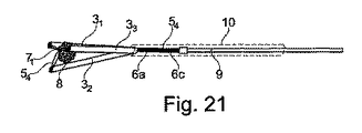
図21は、図19の実施形態を図18に示される位置に類似したスネア構造11の収縮位置で示し、捕捉された物体を例えばヒト又は動物の組織流路から取り出すことができるように、スネア構造11が捕捉された物体8を確実に保持する。図21において、器具は、プルロッド9と、屈曲チューブ31、32、33から後方に且つ近位に延在する締め縄状ワイヤのベース部分6a、6cとが軸方向に移動できるように収容されるシャフトケース10によって補完される。捕捉された物体8が、例えば組織流路から取り出された後に、再び解放されると、締め縄状ワイヤ54は再び軸方向に前方に移動され、この結果として、遠位締め縄状アーチが再び伸びる。これによりスネア構造が自動的に開放することが可能になり、このことは柔軟性屈曲チューブがそれら固有の弾性によりそれら開放された開始位置に戻るという事実により得られる。
21, as can be taken out to the embodiment of FIG. 19 shows a contracted position of the snare structure 1 1 analogous to the position shown in Figure 18, the tissue passage of the captured objects such as human or animal, snare structure 1 1 is securely holds the
それら近位端部分において、屈曲チューブ31、32、33は、互いに、及び/又は、問題になっている種類の従来型スネア器具からそれ自体知られているような器具のシャフト部分の遠位端に提供される接続要素に、適切に固定される。代替的に図22〜図24は、屈曲チューブ31、32、33を固定するさらに可能な方法を示す。図22の実施形態において、前述のシャフトケース10は、例えばホース要素として、接着接合又は締まり嵌めによって、屈曲チューブ31、32、33の近位端部分に直接接続される。図23の実施形態において、ホースケース10は、追加の周囲接続スリーブ11を用いて屈曲チューブ31、32、33の近位端部分に正面で接続され、接続はここでも再び例えば接着接合又は溶接によって達成できる。
At their proximal end portions, the bending
図24の実施形態において、シャフトケース10及び屈曲チューブ31、32、33の接続は、図22の例のように、屈曲チューブの近位端をシャフトケース10の遠位端領域に直接挿入することによって及び続いて固定することによって得られ、軸方向に移動可能なカバーホース12が追加で提供され、カバーホースは特に、より長いスネア構造の場合、追加の閉鎖補助具として使用可能である。
In the embodiment of FIG. 24, the
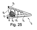
実施形態において、本開示によるスネア器具のスネア構造は、柔軟性捕捉用網構造によって補完可能であり、柔軟性捕捉用網構造は屈曲チューブによって形成される捕捉空間に配置され、屈曲チューブ上に保持される。図25〜図29は、図15〜図24の例示的な実施形態に対応する3つの屈曲チューブ31、32、33及び締め縄状ワイヤ54を備えたスネア構造12の例を再び使用して、これのいくつかの例示的な実施形態を示す。
In an embodiment, the snare structure of the snare device according to the present disclosure can be supplemented by a flexible capture network structure, which is disposed in a capture space formed by the bent tube and retained on the bent tube Is done. 25 to FIG. 29, an example of the snare structure 1 2 with FIGS. 15 Three
図25の実施形態において、らせん状ワイヤ渦巻線131が柔軟性捕捉用網構造として導入され、らせん状ワイヤ渦巻線は例えば締め縄状ワイヤ54のワイヤ材料から作製可能である。らせん状ワイヤ渦巻線131は、捕捉空間の円錐状又は漏斗状の拡張に対応しながら、遠位方向に円錐状に広くなる。図26の実施形態では、円錐台状格子構造132が漏斗状又は円錐状の捕捉空間内の柔軟性捕捉用網構造として機能する。
In the embodiment of FIG. 25, is introduced as a helical wire spirals 13 1 flexible capturing network structure, helical wire spiral can be made of wire material lanyard shaped
図27の実施形態において、屈曲チューブ31、32、33はわずかにより長く、捕捉空間の円錐状拡張部分に隣接する円筒部分を形成する。円筒状格子133が柔軟性捕捉用網構造として捕捉空間の円筒部分に導入される。同様に、図28の実施形態では、円筒状織物要素134が捕捉空間の円筒部分に導入される。さらなる代替的な形態として、図29の実施形態では、円筒状ハニカム織物要素135が柔軟性捕捉用網構造として捕捉空間の円筒部分に導入される。
In the embodiment of FIG. 27, the
図25〜図29の実施形態において、遠位捕捉開口は、締め縄状ワイヤ54の交差締め縄状アーチによって及びその結果として得られる結び目領域71によって、同じく閉鎖される。特定の使用において、柔軟性捕捉用網構造131〜135の導入により、スネア構造12の捕捉する特徴及び確保する特徴を改善できる。円筒状捕捉用網構造133〜135は例えば医療用ステントの分野の当業者にそれ自体知られている種類の構造とすることができる。従って本開示のスネア器具は、ステントを身体組織に導入する働きをすることもできる一方、スネア構造が続いて開放され、器具が引き戻され、このプロセス中、ステントが遠位捕捉開口を介して捕捉空間から逃れることができる。
In the embodiment of FIGS. 25 29, the distal capturing opening, the lanyard shaped
図30は、図15〜図19の実施形態に示されるスネア構造11の実施形態を示し、屈曲ワイヤ31、32、33がらせん状ばねチューブ141、142、143によって各々形成される。代替的な構成において、屈曲チューブの1つだけ又はいくつかをこのようにらせん状ばねチューブから製造し、1つ又は複数の他の屈曲チューブを前述の例示的な実施形態の屈曲チューブのように、例えばモノフィラメントワイヤチューブから又はプラスチックホース材料から、製造することも可能であることが分かるだろう。
Figure 30 each show an embodiment of the snare structure 1 1 shown in the embodiment of FIGS. 15 to 19, by bending the
図31は、4つの屈曲チューブと、4つの締め縄状ワイヤ58の配置とを備えたスネア構造の実施形態を示し、4つの締め縄状ワイヤ58は、それら締め縄状アーチ6bにより、各々スネアの円周の半分だけ延在し、交差して配置されない。
Figure 31 includes four bending tubes, illustrate embodiments of the snare structure with the arrangement of the four lanyard shaped
図32〜図35は、図31の実施形態の締め縄状ワイヤ配置の平面図を、徐々に閉鎖する位置で示し、図31及び図32の完全に開放した位置から始まる。図32〜図35の順序から分かるように、関連するスネア構造が引っ張られて閉鎖されるにつれて、遠位捕捉開口が、締め縄状ワイヤ58の収縮する遠位締め縄状アーチ6bによって徐々に狭められて閉鎖される。
32 to 35 show a plan view of the lanyard wire arrangement of the embodiment of FIG. 31 in a gradually closed position, starting from the fully open position of FIGS. 31 and 32. As can be seen from the sequence of FIGS. 32 35, as it is closed by being pulled associated snare structure, the distal capturing opening is gradually by the
図36〜図39は、図32〜図35の順序に対応する締め縄状ワイヤ58の及びそれら締め縄状アーチ6bの収縮の順序において、4つの締め縄状ワイヤ58が配置され、それら4つの締め縄状アーチ6bが互いに交差する実施形態を示す。このため、各締め縄状ワイヤ58は、その2つのベース部分6a、6bの間のその遠位締め縄状アーチ6bが、第1の部分において、3つの他の締め縄状アーチの第1の締め縄状アーチの上に、すなわちその前に延在し、第2の部分において、3つの他の締め縄状アーチの第2の締め縄状アーチの下に、すなわちその後ろに延在する。
FIGS. 36 39, in the order of contraction of the lanyard shaped
図32〜図35の例における非交差構造と比べて、締め縄状アーチ6bの交差構造を有する図36〜図39による実施形態は、せん断効果を提供し、このことは例えば、捕捉すべき粒子を組織壁からより簡単に切り離すことができることを意味する。さらに、締め縄状アーチの交差は、遠位捕捉開口を閉鎖するための締め縄状アーチ6bの織物状の交差を提供する。他方で、図32〜図35の実施形態の他の同一条件のもとでは、スネア構造を収縮するためにより弱い引張り力を適用しなければならない。
Compared to the non-intersecting structure in the examples of FIGS. 32 to 35, the embodiment according to FIGS. 36 to 39 with the crossing structure of the lanyard-
これまで考察した例示的な実施形態では、2つの締め縄状ワイヤのベース部分が、各屈曲チューブに収容される。しかしながら、本開示はまた、締め縄状ワイヤのベース部分が1つだけ屈曲ワイヤの1つ、いくつか、又は全てに収容されるスネア器具にも関連する。図40〜図43は、図31〜図39の例示的な実施形態による4つの屈曲チューブを備えたスネア構造の例示的な実施形態を示す。 In the exemplary embodiments discussed so far, a base portion of two lanyard wires is housed in each flex tube. However, the present disclosure also relates to a snare instrument in which only one base portion of the lanyard wire is housed in one, some, or all of the bending wires. 40-43 illustrate an exemplary embodiment of a snare structure with four flex tubes according to the exemplary embodiment of FIGS. 31-39.
図40において、スネア構造の締め縄状ワイヤ配置は、2つの締め縄状ワイヤ59を含み、それら締め縄状アーチ6bが、各々の場合に3つの屈曲チューブの円周方向間隔だけ、従って約270°の円周方向長さにわたって、スネア構造の円周方向に延在する。4つの締め縄状ワイヤベース部分6a、6cの各々は、それ自体の屈曲チューブに収容される。
In Figure 40, lanyard shaped wire placement of the snare structure includes two lanyard shaped
図41〜図43は、交差締め縄状アーチ6bを備えたこの締め縄状ワイヤ配置の収縮挙動を示す。図41は、図40に対応する完全に開放された位置を示す。図42は、収縮された中間位置を示し、図43は、実質的に完全に収縮された位置を示す。他の例示的な実施形態のように、図41〜図43に示される締め縄状ワイヤのベース部分6a、6cの位置は、関連する4つの屈曲チューブの遠位端の位置を表す。上記の例示的な実施形態のように、屈曲チューブは、それら遠位端で、スネア構造の収縮の結果として半径方向内側に互いに移動するように構成される。
FIGS. 41-43 show the contraction behavior of this lanyard wire arrangement with
図44〜図47は、6つの屈曲チューブを備えたスネア構造について、図40〜図43の締め縄状ワイヤ配置の一実施形態を示し、6つの屈曲チューブの各々に、ここでも締め縄状ワイヤのベース部分が1つだけ収容される。 44-47 show one embodiment of the lanyard wire arrangement of FIGS. 40-43 for a snare structure with six bend tubes, each of which is again a lanyard wire. Only one base portion is accommodated.
図44は、3つの使用される締め縄状ワイヤ510のうちの1つの平面図を示し、図45は、交差締め縄状アーチ6bを備えた配置において全部で3つの締め縄状ワイヤ510の関連配置を示す。この場合、各締め縄状ワイヤ510の締め縄状アーチ6bは、スネア構造の円周方向において、5つの屈曲チューブの円周方向間隔の円周方向長さで、従って約300°の円周方向角度にわたって延在する。図46は、締め縄状アーチ配置の収縮の中間段階を示し、図47は、事実上完全に収縮された状態における締め縄状アーチ構造を示す。締め縄状ワイヤのベース部分6a、6cの位置によって示される屈曲ワイヤの遠位端は、遠位捕捉開口を狭めるように、収縮移動によって半径方向内側に互いの方に移動するように構成される。加えて、交差締め縄状アーチ構造は、遠位捕捉開口の中央領域に結び目領域72の形成をもたらし、この結び目を用いることによって捕捉開口がさらに閉鎖される。
FIG. 44 shows a plan view of one of the three used
それぞれ屈曲チューブ内に締め縄状ワイヤのベース部分を1つだけ備えた実施形態は、スネア器具の特に小型且つ軽量の構成と、相対的に小さい直径の屈曲ワイヤの使用を可能にする。さらに、これら変形は製造が比較的簡単である。 Embodiments each having only one lanyard wire base portion within the flex tube allow for a particularly small and lightweight configuration of the snare instrument and the use of a relatively small diameter bend wire. Furthermore, these variants are relatively easy to manufacture.
図48及び図49は、4つの屈曲ワイヤ34、35、36、37から構成されたスネア器具13の一実施形態を示し、4つの屈曲ワイヤは、スネアの開放位置において漏斗状に外側に広くなる。スネア器具13は、締め縄状ワイヤ配置によって収縮可能であり、このために、例えば図31〜図43の実施形態の締め縄状ワイヤ配置の1つを使用可能である。対応する締め縄状ワイヤ511が、それら遠位締め縄状アーチ部分から、屈曲チューブ34〜37を通って延在し、後続の撚り合せ部分は、器具のシャフト領域全体を通って、シャフトケース10によって囲まれ、器具の近位制御部分(図示せず)まで延在する。図48に示される開放位置から、スネア構造13は、図49による完全な収縮位置まで収縮可能であり、完全な収縮位置では、その屈曲チューブ34〜37が器具の長手方向とほぼ平行に延在し、遠位捕捉開口は大部分が閉鎖される。
48 and 49, four
図50は、図48及び図49の器具のさらなる実施形態を示し、この実施形態は図27〜図29の例示的な実施形態による追加の円筒状捕捉空間を備えたスネア構造14を有する。図24の例示的な実施形態のように、シャフトケース10は、軸方向に移動可能なカバーホース又はカバーチューブ12を追加的に装備する。図50は、スネア構造14の完全に開放された位置にある器具を示す。
Figure 50 shows a further embodiment of the apparatus of FIGS. 48 and 49, this embodiment has the snare structure 1 4 with additional cylindrical trapping space in accordance with an exemplary embodiment of FIGS. 27 29. As with the exemplary embodiment of FIG. 24, the
図51は、図50の器具をスネア構造14の所定位置で示し、所定位置では締め縄状ワイヤ511が完全な範囲まで軸方向に引き戻されている。スネア構造14の球状の形状及び比較的長い長さのために、スネア構造14のわずかな残留隆起が残るが、残留隆起はカバーチューブ12を用いてさらに圧縮できる。このため、カバーチューブ12は、図52に示されるように軸方向に前方に移動される。このようにして、カバーチューブ12は、通常であれば締め縄状ワイヤ58の軸方向の後退によって行われるスネア構造14の閉鎖を支援する。軸方向に移動可能なカバーホース12によってもたらされるこの支援型閉鎖動作は、より長い器具及び/又は図50〜図52のスネア構造14のような球状スネア構造の場合に特に有利である。この手段によって、締め縄状ワイヤ58の引張り力および引張り荷重は、比較的低めに保ち続けることができる。このことは、スネア構造を収縮するために一緒に押圧しなければならない図25〜図29の網構造131〜135の1つのような柔軟性捕捉用網構造がスネア構造の捕捉空間に追加的に導入される場合に特にあてはまる。
Figure 51 is a device of Figure 50 shown in a predetermined position of the snare structure 1 4, lanyard shaped
上記開示の例示的な実施形態は、締め縄状ワイヤ配置によって収縮可能な有利なスネア構造を備えたスネア器具を提供し、この締め縄状ワイヤ配置では、締め縄状ワイヤのすくなくとも1つの締め縄状アーチが、スネア構造の遠位領域で、スネア構造の円周方向において少なくとも2つの屈曲チューブの円周方向間隔の円周方向長さで延在する。このことは、スネア構造の及びその遠位捕捉開口の収縮に、及び、捕捉空間に捕捉される物体の意図しない逃れに対抗する遠位捕捉開口の閉鎖に、有利に働く。本発明によるスネア器具のさらなる代替実施形態は、当業者に容易に明らかになるように、前述した例示の対策の組合せから実現可能であることが分かるだろう。 The exemplary embodiments of the above disclosure provide a snare device with an advantageous snare structure that can be retracted by a lanyard wire arrangement, wherein the lanyard wire arrangement includes at least one lanyard of the lanyard wire. A arch extends at a distal region of the snare structure with a circumferential length of at least two bend tube circumferential intervals in the circumferential direction of the snare structure. This favors the contraction of the snare structure and its distal capture opening, and the closure of the distal capture opening against unintentional escape of an object captured in the capture space. It will be appreciated that further alternative embodiments of the snare device according to the present invention can be realized from a combination of the exemplary measures described above, as will be readily apparent to those skilled in the art.
Claims (7)
− 遠位で前記シャフト領域に隣接するスネア領域のスネア構造(1)であって、該スネア構造(1)は、遠位開放スネアを形成する開放位置から引っ張って閉鎖可能であり、前記スネア構造(1)の開放位置において、遠位前方に且つ半径方向外側に放射形状で延在してスネアを形成する複数の柔軟性屈曲チューブ(31、32、33)を有し、該複数の柔軟性屈曲チューブの遠位端(41、42、43)は、複数の締め縄状ワイヤ(51、52、53)が引っ張られることによって前記スネア構造(1)を閉鎖するように、半径方向内側に互いの方へ移動可能である、スネア構造と、
− 複数の締め縄状ワイヤ(51、52、53)であって、該複数の締め縄状ワイヤの各々は、第1ベース部分(6a)が前記シャフト領域から屈曲チューブ(31、32、33)の1つを緩やかに通って該屈曲チューブの遠位端(41、42、43)まで延在し、該遠位端から締め縄状アーチ(6b)が同一の又は別の屈曲チューブ(31、32、33)の遠位端(41、42、43)まで延在し、該遠位端から第2ベース部分(6c)が前記同一の又は別の屈曲チューブ(31、32、33)を緩やかに通って前記シャフト領域まで戻り、前記締め縄状ワイヤの前記第1ベース部分及び前記第2ベース部分(6a、6c)の少なくとも1つが各屈曲チューブ(31、32、33)を通って延在する、複数の締め縄状ワイヤと、
を有し、
前記複数の締め縄状ワイヤ(51、52、53)の前記締め縄状アーチ(6b)が、前記スネア構造(1)の前記開放位置で、かつ円周方向に延在する、
スネア器具(13)において、
各々の締め縄状ワイヤ(51、52、53)の前記第1ベース部分及び前記第2ベース部分(6a、6c)の少なくとも1つが、同一の方向に且つ同期して軸方向に移動可能となるように配置されると共に、前記屈曲チューブ(31、32、33)内を案内され、
複数の締め縄状アーチ(6b)が交差締め縄状構造を形成し、少なくとも1つの締め縄状アーチ(6b)が、第1の部分において第1の他の締め縄状アーチ(6b)の前方に延在し、第2の部分において前記第1の他の締め縄状アーチ(6b)の後方又は第2の他の締め縄状アーチ(6b)の後方に延在する、ことを特徴とするスネア器具。 -The shaft area;
A snare structure (1) of the snare region distally adjacent to the shaft region, the snare structure (1) being closable by being pulled from an open position forming a distal open snare, said snare structure In the open position of (1), it has a plurality of flexible bent tubes (31, 32, 33) extending radially distally and radially outward to form a snare, the plurality of flexibility the distal end of the bent tube (41, 42, 43), the snare structure by a plurality of fastening rope-like wire (51, 52, 53) is pulled (1) so as to close the chain, radially inward A snare structure that can move towards each other,
A plurality of lanyard wires (51, 52, 53), each of the plurality of lanyard wires having a first base portion (6a) bent from the shaft region (31, 32, 33); Extending to one of the distal ends (41, 42, 43) of the bent tube, from which the lanyard arch (6b) is the same or another bent tube (31, 32, 33) extends to the distal end (41, 42, 43) from which the second base portion (6c) loosens the same or another bent tube (31, 32, 33). To the shaft region and at least one of the first base portion and the second base portion (6a, 6c) of the lanyard wire extends through each bent tube (31, 32, 33). A plurality of lanyard wires,
Have
The front Symbol lanyard arches of a plurality of lanyard shaped wires (51, 52, 53) (6b) is in the open position prior Symbol snare structure (1), and extends in the circumferential direction,
In the snare device (13),
At least one of the first base portion and the second base portion (6a, 6c) of each lanyard wire (51, 52, 53) is movable in the same direction and synchronously in the axial direction. And is guided in the bent tube (31, 32, 33) ,
A plurality of lanyard-shaped arches (6b) form a crossed lanyard-shaped structure, and at least one lanyard-shaped arch (6b) is in front of the first other lanyard-shaped arch (6b) in the first portion. Extending in the second portion and behind the first other lanyard arch (6b) or behind the second other lanyard arch (6b). Snare instrument.
Applications Claiming Priority (3)
| Application Number | Priority Date | Filing Date | Title |
|---|---|---|---|
| DE102014208168.8A DE102014208168A1 (en) | 2014-04-30 | 2014-04-30 | Fangkelinstrument with distal Fangkelchstruktur |
| DE102014208168.8 | 2014-04-30 | ||
| PCT/DK2015/050110 WO2015165474A1 (en) | 2014-04-30 | 2015-04-29 | A snare instrument with a distal snare structure |
Publications (3)
| Publication Number | Publication Date |
|---|---|
| JP2017516532A JP2017516532A (en) | 2017-06-22 |
| JP2017516532A5 JP2017516532A5 (en) | 2018-05-10 |
| JP6585626B2 true JP6585626B2 (en) | 2019-10-02 |
Family
ID=53174750
Family Applications (1)
| Application Number | Title | Priority Date | Filing Date |
|---|---|---|---|
| JP2016565331A Active JP6585626B2 (en) | 2014-04-30 | 2015-04-29 | Snare instrument having a distal snare structure |
Country Status (6)
| Country | Link |
|---|---|
| US (2) | US10335185B2 (en) |
| EP (2) | EP3136997B1 (en) |
| JP (1) | JP6585626B2 (en) |
| CN (1) | CN106232039B (en) |
| DE (1) | DE102014208168A1 (en) |
| WO (1) | WO2015165474A1 (en) |
Families Citing this family (8)
| Publication number | Priority date | Publication date | Assignee | Title |
|---|---|---|---|---|
| DE102014208168A1 (en) | 2014-04-30 | 2015-11-19 | Epflex Feinwerktechnik Gmbh | Fangkelinstrument with distal Fangkelchstruktur |
| US10111677B2 (en) * | 2014-12-11 | 2018-10-30 | Boston Scientific Scimed, Inc. | Retrieval devices and related methods of use |
| US11653942B2 (en) * | 2015-03-24 | 2023-05-23 | Boston Scientific Scimed, Inc. | Retrieval devices and related methods of use |
| DE102017205725B4 (en) | 2017-04-04 | 2018-12-06 | Epflex Feinwerktechnik Gmbh | Medical claw instrument |
| WO2019083757A1 (en) * | 2017-10-26 | 2019-05-02 | Teleflex Innovations S.A.R.L. | Subintimal catheter device and assembly |
| JP7281475B2 (en) | 2017-11-09 | 2023-05-25 | 11 ヘルス アンド テクノロジーズ リミテッド | Stoma monitoring system and method |
| USD893514S1 (en) | 2018-11-08 | 2020-08-18 | 11 Health And Technologies Limited | Display screen or portion thereof with graphical user interface |
| US11006973B2 (en) * | 2019-01-17 | 2021-05-18 | Olympus Corporation | Method for constricting tissue |
Family Cites Families (55)
| Publication number | Priority date | Publication date | Assignee | Title |
|---|---|---|---|---|
| DE1414809B2 (en) | 1959-02-26 | 1970-04-16 | Hughes Aircraft Company, Culver City, Calif. (V.St.A.) | Electron beam halftone storage tube |
| DE4317914A1 (en) | 1993-05-28 | 1994-12-01 | Haas Carl Gmbh & Co | Flexible endoscope tube |
| US5656011A (en) | 1994-04-28 | 1997-08-12 | Epflex Feinwerktechnik Gmbh | Endoscope tube system |
| US6350266B1 (en) * | 1995-02-02 | 2002-02-26 | Scimed Life Systems, Inc. | Hybrid stone retrieval device |
| DE19512047C2 (en) | 1995-03-31 | 1998-09-03 | Epflex Feinwerktech Gmbh | Guide wire, in particular for a surgical instrument |
| DE19607595C2 (en) | 1996-02-29 | 2000-01-20 | Epflex Feinwerktech Gmbh | Guide wire core, in particular for a surgical instrument |
| US5954713A (en) * | 1996-07-12 | 1999-09-21 | Newman; Fredric A. | Endarterectomy surgical instruments and procedure |
| DE19647761C1 (en) | 1996-11-19 | 1998-01-08 | Epflex Feinwerktech Gmbh | Manual control for endoscope with handle and endoscope tube arrangement |
| AU7266298A (en) | 1997-04-29 | 1998-11-24 | Raymond F. Lippitt | Annularly expanding and retracting gripping and releasing mechanism |
| WO1998048709A1 (en) * | 1997-04-29 | 1998-11-05 | Lippitt Raymond F | Positively expanding and retracting medical extractor |
| DE19751194C1 (en) | 1997-11-19 | 1999-05-06 | Epflex Feinwerktech Gmbh | Wire dispenser for elastically deformable wires |
| DE19823414A1 (en) | 1998-05-26 | 1999-06-17 | Epflex Feinwerktech Gmbh | Spiral wire guide tube made of two types of wire for surgical procedure |
| DE19928272C2 (en) | 1999-06-21 | 2003-08-14 | Ep Flex Feinwerktechnik Gmbh | Elastic bendable endoscope tube part |
| DE10113713C1 (en) | 2001-03-19 | 2002-12-05 | Epflex Feinwerktech Gmbh | Flexible endoscope tube uses linked individual elements each provided by 2 or more segments spaced apart by intermediate axial gaps |
| US7101379B2 (en) | 2001-04-02 | 2006-09-05 | Acmi Corporation | Retrieval basket for a surgical device and system and method for manufacturing same |
| DE10138953B4 (en) | 2001-08-03 | 2005-03-24 | Epflex Feinwerktechnik Gmbh | Guidewire with core wire and coil spring sheath |
| DE10160922A1 (en) | 2001-12-06 | 2003-05-15 | Epflex Feinwerktech Gmbh | Endoscope tube piece e.g. for surgical endoscope, has interlocking elements on facing tube segments surfaces for stabilizing torsional or lateral forces |
| US7041108B2 (en) | 2002-05-28 | 2006-05-09 | Lippitt Extractor Company, Llc | Grasper mechanism with biased fixed flexure elements |
| DE10243261B4 (en) | 2002-09-17 | 2006-03-09 | Epflex Feinwerktechnik Gmbh | Guide wire with marking pattern |
| DE102004055375B4 (en) | 2004-11-08 | 2007-12-06 | Epflex Feinwerktechnik Gmbh | Multi-wire unit and manufacturing method thereof |
| DE102005022688B4 (en) | 2005-05-12 | 2011-06-30 | EPflex Feinwerktechnik GmbH, 72581 | Guidewire for a medical instrument |
| DE102005030010B4 (en) | 2005-06-17 | 2007-12-27 | Epflex Feinwerktechnik Gmbh | Stone catcher unit |
| US8157818B2 (en) * | 2005-08-01 | 2012-04-17 | Ension, Inc. | Integrated medical apparatus for non-traumatic grasping, manipulating and closure of tissue |
| DE102005040214A1 (en) | 2005-08-15 | 2007-03-01 | Epflex Feinwerktechnik Gmbh | Multi-wire unit and manufacturing method thereof |
| DE102005042216A1 (en) | 2005-09-05 | 2007-03-08 | Andramed Gmbh | Catheter for the removal of foreign bodies, comprises a tip which is slightly angled, and a loop shaped section |
| DE102006002531A1 (en) | 2006-01-11 | 2007-07-12 | Epflex Feinwerktechnik Gmbh | Multiwire instrument, in particular for endoscopes |
| DE102006018489A1 (en) | 2006-02-15 | 2007-10-25 | Epflex Feinwerktechnik Gmbh | Controlled stiffenable hose |
| US20070250149A1 (en) | 2006-04-21 | 2007-10-25 | Abbott Laboratories | Stiffening Support Catheters and Methods for Using the Same |
| DE102006024094A1 (en) | 2006-05-17 | 2007-11-22 | Epflex Feinwerktechnik Gmbh | Controlled stiffenable guidewire unit |
| DE102006024095A1 (en) | 2006-05-17 | 2007-12-06 | Epflex Feinwerktechnik Gmbh | Pressure connection device for a guide wire unit |
| DE102006047675A1 (en) | 2006-09-28 | 2008-04-03 | Epflex Feinwerktechnik Gmbh | Guidewire with core and distal sheath |
| US9072514B2 (en) | 2006-10-05 | 2015-07-07 | Thomas P. Knapp | Shape memory filament for suture management |
| US20080269774A1 (en) * | 2006-10-26 | 2008-10-30 | Chestnut Medical Technologies, Inc. | Intracorporeal Grasping Device |
| DE102007005559B4 (en) | 2007-01-24 | 2014-11-06 | Epflex Feinwerktechnik Gmbh | Guidewire with electrical functional element |
| WO2009112048A1 (en) | 2008-03-11 | 2009-09-17 | Epflex Feinwerktechnik Gmbh | Guide wire having marking pattern |
| US8617177B2 (en) | 2008-04-01 | 2013-12-31 | Coloplast A/S | Wire basket unit having fixing disk element |
| JP5191338B2 (en) * | 2008-10-01 | 2013-05-08 | Hoya株式会社 | Bipolar high-frequency snare for endoscope |
| JPWO2010090089A1 (en) * | 2009-02-06 | 2012-08-09 | オリンパスメディカルシステムズ株式会社 | Treatment tool |
| DE102009022379A1 (en) | 2009-05-22 | 2010-11-25 | Epflex Feinwerktechnik Gmbh | Interchangeable handle system, especially for medical instruments |
| DE102009037827A1 (en) | 2009-08-10 | 2011-02-17 | Epflex Feinwerktechnik Gmbh | Medical catheter instrument |
| DE102010007194A1 (en) | 2010-02-05 | 2011-08-11 | EPflex Feinwerktechnik GmbH, 72581 | Hand-operated functional hose element and operating handle for this |
| DE102010010798A1 (en) | 2010-03-09 | 2011-09-15 | Epflex Feinwerktechnik Gmbh | Hand-operated functional hose instrument and operating device therefor |
| US20130018385A1 (en) | 2011-07-11 | 2013-01-17 | Boston Scientific Scimed, Inc. | Polypectomy Snare Device |
| US8469970B2 (en) * | 2011-07-11 | 2013-06-25 | Great Aspirations Ltd. | Apparatus for entrapping and extracting objects from body cavities |
| WO2013018445A1 (en) * | 2011-08-01 | 2013-02-07 | オリンパスメディカルシステムズ株式会社 | Treatment instrument |
| DE102011081445A1 (en) | 2011-08-23 | 2013-02-28 | Epflex Feinwerktechnik Gmbh | Medical guide wire for e.g. MRI application, has wire core whose wire threads are formed by non-metallic fiber that is volume-doped with magnetic resonance-marker, where magnetic resonance-marker is provided between fibers in interstices |
| DE102012208888B4 (en) | 2012-05-25 | 2016-09-01 | Epflex Feinwerktechnik Gmbh | Wire catcher instrument |
| DE102012214785A1 (en) | 2012-08-20 | 2014-02-20 | Epflex Feinwerktechnik Gmbh | Medical guide wire with MR marker |
| DE102012222356B4 (en) | 2012-12-05 | 2017-03-16 | Epflex Feinwerktechnik Gmbh | Medical stone catcher instrument |
| US10582938B2 (en) * | 2013-09-03 | 2020-03-10 | Bosotn Scientific Scimed, Inc. | Medical retrieval devices and related methods of use |
| EP3797717B1 (en) * | 2014-01-10 | 2023-04-05 | Boston Scientific Scimed, Inc. | Expandable basket retrieval device |
| DE102014205366B4 (en) | 2014-03-21 | 2019-03-28 | Coloplast A/S | Catch wire instrument with catch wire structure made of tubular piece |
| DE102014207344A1 (en) | 2014-04-16 | 2015-10-22 | Epflex Feinwerktechnik Gmbh | Safety wire instrument with distal catch structure |
| DE102014208168A1 (en) | 2014-04-30 | 2015-11-19 | Epflex Feinwerktechnik Gmbh | Fangkelinstrument with distal Fangkelchstruktur |
| DE102014222600A1 (en) | 2014-11-05 | 2016-05-12 | Epflex Feinwerktechnik Gmbh | Medical safety wire instrument |
-
2014
- 2014-04-30 DE DE102014208168.8A patent/DE102014208168A1/en not_active Withdrawn
-
2015
- 2015-04-29 WO PCT/DK2015/050110 patent/WO2015165474A1/en active Application Filing
- 2015-04-29 US US15/306,768 patent/US10335185B2/en active Active
- 2015-04-29 EP EP15721559.1A patent/EP3136997B1/en active Active
- 2015-04-29 JP JP2016565331A patent/JP6585626B2/en active Active
- 2015-04-29 EP EP18177501.6A patent/EP3409220B1/en active Active
- 2015-04-29 CN CN201580022484.2A patent/CN106232039B/en active Active
-
2019
- 2019-05-16 US US16/413,639 patent/US11337721B2/en active Active
Also Published As
| Publication number | Publication date |
|---|---|
| EP3136997A1 (en) | 2017-03-08 |
| CN106232039A (en) | 2016-12-14 |
| EP3409220A1 (en) | 2018-12-05 |
| JP2017516532A (en) | 2017-06-22 |
| DE102014208168A1 (en) | 2015-11-19 |
| US10335185B2 (en) | 2019-07-02 |
| US20190262026A1 (en) | 2019-08-29 |
| US20170049472A1 (en) | 2017-02-23 |
| US11337721B2 (en) | 2022-05-24 |
| WO2015165474A1 (en) | 2015-11-05 |
| CN106232039B (en) | 2019-04-16 |
| EP3409220B1 (en) | 2022-03-30 |
| EP3136997B1 (en) | 2020-11-18 |
Similar Documents
| Publication | Publication Date | Title |
|---|---|---|
| JP6585626B2 (en) | Snare instrument having a distal snare structure | |
| US20170143358A1 (en) | Retrieval device | |
| JP6194381B2 (en) | Collection device | |
| RU2011106747A (en) | MULTILAYERED MEDICAL DEVICE FOR TARGET TREATMENT TREATMENT AND METHOD RELATED TO IT | |
| JP2008036418A5 (en) | ||
| US9795401B2 (en) | Medical retrieval devices and related methods of use | |
| US9924960B2 (en) | Endoscope treatment tool | |
| US11259822B2 (en) | Device for retrieving a body from a tubular structure | |
| JP6749336B2 (en) | Collection device and related usage | |
| JP2017516532A5 (en) | ||
| US20220401112A1 (en) | Medical instrument | |
| JP4959787B2 (en) | Artificial blood vessel stent insertion device | |
| US20160089170A1 (en) | Invertable medical retrieval devices and methods | |
| JP6549609B2 (en) | A capture device having a capture structure consisting of tube sections | |
| KR101586615B1 (en) | Branched stent | |
| WO2023014919A1 (en) | Endoscopic loop systems and methods of use | |
| JP7114482B2 (en) | stent | |
| EP3367874A1 (en) | Colonic polyp removal | |
| JP2005204807A (en) | Basket type grasping forceps |
Legal Events
| Date | Code | Title | Description |
|---|---|---|---|
| A521 | Request for written amendment filed |
Free format text: JAPANESE INTERMEDIATE CODE: A523 Effective date: 20180322 |
|
| A621 | Written request for application examination |
Free format text: JAPANESE INTERMEDIATE CODE: A621 Effective date: 20180322 |
|
| A131 | Notification of reasons for refusal |
Free format text: JAPANESE INTERMEDIATE CODE: A131 Effective date: 20181204 |
|
| A601 | Written request for extension of time |
Free format text: JAPANESE INTERMEDIATE CODE: A601 Effective date: 20190304 |
|
| A521 | Request for written amendment filed |
Free format text: JAPANESE INTERMEDIATE CODE: A523 Effective date: 20190604 |
|
| TRDD | Decision of grant or rejection written | ||
| A01 | Written decision to grant a patent or to grant a registration (utility model) |
Free format text: JAPANESE INTERMEDIATE CODE: A01 Effective date: 20190806 |
|
| A61 | First payment of annual fees (during grant procedure) |
Free format text: JAPANESE INTERMEDIATE CODE: A61 Effective date: 20190905 |
|
| R150 | Certificate of patent or registration of utility model |
Ref document number: 6585626 Country of ref document: JP Free format text: JAPANESE INTERMEDIATE CODE: R150 |
|
| R250 | Receipt of annual fees |
Free format text: JAPANESE INTERMEDIATE CODE: R250 |
|
| R250 | Receipt of annual fees |
Free format text: JAPANESE INTERMEDIATE CODE: R250 |