JP6559155B2 - Single motor type transmission mechanism actuator with slider mechanism that selects and shifts gear stage of automobile transmission mechanism device - Google Patents
Single motor type transmission mechanism actuator with slider mechanism that selects and shifts gear stage of automobile transmission mechanism device Download PDFInfo
- Publication number
- JP6559155B2 JP6559155B2 JP2016559194A JP2016559194A JP6559155B2 JP 6559155 B2 JP6559155 B2 JP 6559155B2 JP 2016559194 A JP2016559194 A JP 2016559194A JP 2016559194 A JP2016559194 A JP 2016559194A JP 6559155 B2 JP6559155 B2 JP 6559155B2
- Authority
- JP
- Japan
- Prior art keywords
- slider mechanism
- shift
- transmission mechanism
- actuator
- slider
- Prior art date
- Legal status (The legal status is an assumption and is not a legal conclusion. Google has not performed a legal analysis and makes no representation as to the accuracy of the status listed.)
- Expired - Fee Related
Links
Images


Classifications
-
- F—MECHANICAL ENGINEERING; LIGHTING; HEATING; WEAPONS; BLASTING
- F16—ENGINEERING ELEMENTS AND UNITS; GENERAL MEASURES FOR PRODUCING AND MAINTAINING EFFECTIVE FUNCTIONING OF MACHINES OR INSTALLATIONS; THERMAL INSULATION IN GENERAL
- F16H—GEARING
- F16H61/00—Control functions within control units of change-speed- or reversing-gearings for conveying rotary motion ; Control of exclusively fluid gearing, friction gearing, gearings with endless flexible members or other particular types of gearing
- F16H61/26—Generation or transmission of movements for final actuating mechanisms
- F16H61/28—Generation or transmission of movements for final actuating mechanisms with at least one movement of the final actuating mechanism being caused by a non-mechanical force, e.g. power-assisted
-
- F—MECHANICAL ENGINEERING; LIGHTING; HEATING; WEAPONS; BLASTING
- F16—ENGINEERING ELEMENTS AND UNITS; GENERAL MEASURES FOR PRODUCING AND MAINTAINING EFFECTIVE FUNCTIONING OF MACHINES OR INSTALLATIONS; THERMAL INSULATION IN GENERAL
- F16H—GEARING
- F16H59/00—Control inputs to control units of change-speed- or reversing-gearings for conveying rotary motion
- F16H59/02—Selector apparatus
-
- F—MECHANICAL ENGINEERING; LIGHTING; HEATING; WEAPONS; BLASTING
- F16—ENGINEERING ELEMENTS AND UNITS; GENERAL MEASURES FOR PRODUCING AND MAINTAINING EFFECTIVE FUNCTIONING OF MACHINES OR INSTALLATIONS; THERMAL INSULATION IN GENERAL
- F16H—GEARING
- F16H61/00—Control functions within control units of change-speed- or reversing-gearings for conveying rotary motion ; Control of exclusively fluid gearing, friction gearing, gearings with endless flexible members or other particular types of gearing
- F16H61/26—Generation or transmission of movements for final actuating mechanisms
- F16H61/28—Generation or transmission of movements for final actuating mechanisms with at least one movement of the final actuating mechanism being caused by a non-mechanical force, e.g. power-assisted
- F16H61/32—Electric motors , actuators or related electrical control means therefor
-
- F—MECHANICAL ENGINEERING; LIGHTING; HEATING; WEAPONS; BLASTING
- F16—ENGINEERING ELEMENTS AND UNITS; GENERAL MEASURES FOR PRODUCING AND MAINTAINING EFFECTIVE FUNCTIONING OF MACHINES OR INSTALLATIONS; THERMAL INSULATION IN GENERAL
- F16H—GEARING
- F16H61/00—Control functions within control units of change-speed- or reversing-gearings for conveying rotary motion ; Control of exclusively fluid gearing, friction gearing, gearings with endless flexible members or other particular types of gearing
- F16H61/26—Generation or transmission of movements for final actuating mechanisms
- F16H61/28—Generation or transmission of movements for final actuating mechanisms with at least one movement of the final actuating mechanism being caused by a non-mechanical force, e.g. power-assisted
- F16H61/30—Hydraulic or pneumatic motors or related fluid control means therefor
-
- F—MECHANICAL ENGINEERING; LIGHTING; HEATING; WEAPONS; BLASTING
- F16—ENGINEERING ELEMENTS AND UNITS; GENERAL MEASURES FOR PRODUCING AND MAINTAINING EFFECTIVE FUNCTIONING OF MACHINES OR INSTALLATIONS; THERMAL INSULATION IN GENERAL
- F16H—GEARING
- F16H63/00—Control outputs from the control unit to change-speed- or reversing-gearings for conveying rotary motion or to other devices than the final output mechanism
- F16H63/02—Final output mechanisms therefor; Actuating means for the final output mechanisms
-
- F—MECHANICAL ENGINEERING; LIGHTING; HEATING; WEAPONS; BLASTING
- F16—ENGINEERING ELEMENTS AND UNITS; GENERAL MEASURES FOR PRODUCING AND MAINTAINING EFFECTIVE FUNCTIONING OF MACHINES OR INSTALLATIONS; THERMAL INSULATION IN GENERAL
- F16H—GEARING
- F16H61/00—Control functions within control units of change-speed- or reversing-gearings for conveying rotary motion ; Control of exclusively fluid gearing, friction gearing, gearings with endless flexible members or other particular types of gearing
- F16H61/26—Generation or transmission of movements for final actuating mechanisms
- F16H61/28—Generation or transmission of movements for final actuating mechanisms with at least one movement of the final actuating mechanism being caused by a non-mechanical force, e.g. power-assisted
- F16H2061/2838—Arrangements with single drive motor for selecting and shifting movements, i.e. one motor used for generating both movements
-
- F—MECHANICAL ENGINEERING; LIGHTING; HEATING; WEAPONS; BLASTING
- F16—ENGINEERING ELEMENTS AND UNITS; GENERAL MEASURES FOR PRODUCING AND MAINTAINING EFFECTIVE FUNCTIONING OF MACHINES OR INSTALLATIONS; THERMAL INSULATION IN GENERAL
- F16H—GEARING
- F16H61/00—Control functions within control units of change-speed- or reversing-gearings for conveying rotary motion ; Control of exclusively fluid gearing, friction gearing, gearings with endless flexible members or other particular types of gearing
- F16H61/26—Generation or transmission of movements for final actuating mechanisms
- F16H61/28—Generation or transmission of movements for final actuating mechanisms with at least one movement of the final actuating mechanism being caused by a non-mechanical force, e.g. power-assisted
- F16H2061/2869—Cam or crank gearing
-
- F—MECHANICAL ENGINEERING; LIGHTING; HEATING; WEAPONS; BLASTING
- F16—ENGINEERING ELEMENTS AND UNITS; GENERAL MEASURES FOR PRODUCING AND MAINTAINING EFFECTIVE FUNCTIONING OF MACHINES OR INSTALLATIONS; THERMAL INSULATION IN GENERAL
- F16H—GEARING
- F16H61/00—Control functions within control units of change-speed- or reversing-gearings for conveying rotary motion ; Control of exclusively fluid gearing, friction gearing, gearings with endless flexible members or other particular types of gearing
- F16H61/26—Generation or transmission of movements for final actuating mechanisms
- F16H61/28—Generation or transmission of movements for final actuating mechanisms with at least one movement of the final actuating mechanism being caused by a non-mechanical force, e.g. power-assisted
- F16H2061/2884—Screw-nut devices
-
- F—MECHANICAL ENGINEERING; LIGHTING; HEATING; WEAPONS; BLASTING
- F16—ENGINEERING ELEMENTS AND UNITS; GENERAL MEASURES FOR PRODUCING AND MAINTAINING EFFECTIVE FUNCTIONING OF MACHINES OR INSTALLATIONS; THERMAL INSULATION IN GENERAL
- F16H—GEARING
- F16H61/00—Control functions within control units of change-speed- or reversing-gearings for conveying rotary motion ; Control of exclusively fluid gearing, friction gearing, gearings with endless flexible members or other particular types of gearing
- F16H61/26—Generation or transmission of movements for final actuating mechanisms
- F16H61/28—Generation or transmission of movements for final actuating mechanisms with at least one movement of the final actuating mechanism being caused by a non-mechanical force, e.g. power-assisted
- F16H61/30—Hydraulic or pneumatic motors or related fluid control means therefor
- F16H2061/308—Modular hydraulic shift units, i.e. preassembled actuator units for select and shift movements adapted for being mounted on transmission casing
-
- F—MECHANICAL ENGINEERING; LIGHTING; HEATING; WEAPONS; BLASTING
- F16—ENGINEERING ELEMENTS AND UNITS; GENERAL MEASURES FOR PRODUCING AND MAINTAINING EFFECTIVE FUNCTIONING OF MACHINES OR INSTALLATIONS; THERMAL INSULATION IN GENERAL
- F16H—GEARING
- F16H61/00—Control functions within control units of change-speed- or reversing-gearings for conveying rotary motion ; Control of exclusively fluid gearing, friction gearing, gearings with endless flexible members or other particular types of gearing
- F16H61/26—Generation or transmission of movements for final actuating mechanisms
- F16H61/28—Generation or transmission of movements for final actuating mechanisms with at least one movement of the final actuating mechanism being caused by a non-mechanical force, e.g. power-assisted
- F16H61/32—Electric motors , actuators or related electrical control means therefor
- F16H2061/326—Actuators for range selection, i.e. actuators for controlling the range selector or the manual range valve in the transmission
Landscapes
- Engineering & Computer Science (AREA)
- General Engineering & Computer Science (AREA)
- Mechanical Engineering (AREA)
- Gear-Shifting Mechanisms (AREA)
- Connection Of Motors, Electrical Generators, Mechanical Devices, And The Like (AREA)
- Transmission Devices (AREA)
- Gasket Seals (AREA)
Description
本発明は、複数のギヤ段を形成すべく複数の変速段を有する自動車伝動機構装置用のシングルモータ型伝動機構アクチュエータ(1−Motor−Getriebeaktor)に関する。 The present invention relates to a single motor type transmission mechanism actuator (1-Motor-Getriebeaktor) for an automobile transmission mechanism apparatus having a plurality of shift stages to form a plurality of gear stages.
本発明に係る伝動機構アクチュエータとは、特に、自動車内で下記装置の少なくとも1つを操作する(車両伝動機構、クラッチ及びブレーキを操作、セレクト及び/又はシフトする)ように働く伝動機構アクチュエータと解すべきである。 The transmission mechanism actuator according to the present invention is particularly understood as a transmission mechanism actuator that operates to operate (select, and / or shift a vehicle transmission mechanism, a clutch and a brake) at least one of the following devices in an automobile. Should.
公知のように、自動車伝動機構、例えばオートメーテッドマニュアルトランスミッション(automatisiertes Schaltgetriebe:ASG)、パラレルシフトトランスミッション(Parallelschaltgetriebe:PSG)若しくはデュアルクラッチトランスミッション(Doppelkupplungsgetriebe:DKG)、またはその他の類似の伝動機構のギヤ段を入れたり外したりすることは、伝動機構アクチュエータにより行うことができ、その際、伝動機構アクチュエータは、「外部の伝動機構切り換え部(aeussere Getriebeschaltung)」を形成している。 As is well known, automotive transmission mechanisms such as automated manual transmissions (ASG), parallel shift transmissions (Parscheltgetriebe: PSG) or dual clutch transmissions (Doppelupplingsgetries or other gears of DK gear, other gears: The transmission / removal can be performed by a transmission mechanism actuator, in which case the transmission mechanism actuator forms an “external transmission mechanism switching unit”.
例えば独国特許出願公開第102004038955号明細書において、伝動機構内でセレクト運動とシフト運動とを実施するのに、1つの電動モータしか自動車の伝動機構アクチュエータ内で使用しないことが公知である。それゆえ、相応の伝動機構アクチュエータは、シングルモータ型伝動機構アクチュエータともいう。 For example, it is known from DE 102004038955 that only one electric motor is used in the transmission mechanism actuator of a motor vehicle in order to carry out the select and shift movements in the transmission mechanism. Therefore, the corresponding transmission mechanism actuator is also referred to as a single motor type transmission mechanism actuator.
さらに、本件出願人の独国特許出願公開第102006054901号明細書において、このシングルモータ型伝動機構アクチュエータを、(伝動機構アクチュエータのための駆動ユニットとしての)電動モータの一方向の回転がシフト運動を引き起こし、電動モータの他方向の相応の運動が伝動機構のシフト軸のセレクト運動を引き起こすように構成することが公知である。シフト運動とセレクト運動とを切り換えるために、伝動機構アクチュエータは、シフト軸のシフト運動またはセレクト運動を引き起こすべく、スピンドルナットを対応するラックまたは歯車に連結する接続装置を備えている。 Furthermore, in German Patent Application Publication No. 102006054901 of the applicant of the present application, this single motor type transmission mechanism actuator has a unidirectional rotation of an electric motor (as a drive unit for the transmission mechanism actuator) to perform a shift motion. It is known that a corresponding movement in the other direction of the electric motor causes a selection movement of the shift shaft of the transmission mechanism. In order to switch between the shift movement and the selection movement, the transmission mechanism actuator is provided with a connecting device for connecting the spindle nut to the corresponding rack or gear in order to cause a shift movement or a selection movement of the shift shaft.
さらに、独国特許出願公開第102006017158号明細書において、円筒状の周面と、円筒状の周面に配置され、軸方向に間隔をおいた複数の環状溝とを有する、固定に配置される第1のスライダ機構部分を有するスライダ機構(Kulisse)が公知である。さらにスライダ機構は、軸方向で可動かつ回転可動または旋回可動に配置される第2のスライダ機構部分を有し、第2のスライダ機構部分は、軸方向で相対移動不能かつ相対回動不能にシフト軸に結合されている。第2のスライダ機構部分は、その軸方向位置に応じて、その都度、第1のスライダ機構部分の、軸方向で間隔をおいた溝内に旋回可能である。つまり、スライダ機構は、伝動機構アクチュエータの調節可能性、つまり伝動機構アクチュエータのシフト軸の調節可能性を、シフトゲート/セレクトゲートアッセンブリに応じた調節可能性に実質的に限定するガイド装置である。すなわち、スライダ機構は、シフト軸の回動可能性がこのシフト軸の軸方向位置次第であることかつ/又はシフト軸の軸方向可動性がこのシフト軸の旋回位置または回動位置次第であるようにする。このスライダ機構の場合、環状溝間に配置される突起には、各溝の両側に面取り部が設けられており、その結果、第2のスライダ機構部分は、第1のスライダ機構部分内に容易に旋回できるようになっている。 Furthermore, in DE 102006017158, a cylindrical peripheral surface and a plurality of annular grooves disposed on the cylindrical peripheral surface and spaced apart in the axial direction are fixedly disposed. A slider mechanism (Kulisse) having a first slider mechanism portion is known. Further, the slider mechanism has a second slider mechanism portion that is movable in the axial direction, and is rotatably or pivotally movable. The second slider mechanism portion is shifted so as not to be relatively movable and relatively unrotable in the axial direction. It is connected to the shaft. The second slider mechanism part can be swung in the axially spaced grooves of the first slider mechanism part each time depending on its axial position. That is, the slider mechanism is a guide device that substantially limits the adjustability of the transmission mechanism actuator, that is, the adjustability of the shift shaft of the transmission mechanism actuator to the adjustability according to the shift gate / select gate assembly. That is, in the slider mechanism, the pivotability of the shift shaft depends on the position of the shift shaft in the axial direction, and / or the axial mobility of the shift shaft depends on the turning position or the rotational position of the shift shaft. To. In the case of this slider mechanism, the protrusions disposed between the annular grooves are provided with chamfered portions on both sides of each groove, and as a result, the second slider mechanism portion can be easily placed in the first slider mechanism portion. You can turn to.
シングルモータ型伝動機構アクチュエータの場合、この両側の面取り部は、しかし、接続装置全体に歪みを与えることになりかねず、その結果、伝動機構アクチュエータの機能に悪影響を及ぼす虞がある。 In the case of a single motor type transmission mechanism actuator, the chamfered portions on both sides, however, may give distortion to the entire connecting device, and as a result, the function of the transmission mechanism actuator may be adversely affected.
自動車伝動機構装置用のシングルモータ型伝動機構アクチュエータの構造に関して、特に、本件出願時には未公開の本件出願人の独国特許出願102013207871号を参照されたい。これをもって、当該刊行物は、その全体が参照により援用されるものとする。 Regarding the structure of a single motor type transmission mechanism actuator for an automobile transmission mechanism device, in particular, reference should be made to the unpublished German patent application 103013207871 of the present applicant at the time of filing this application. This publication is hereby incorporated by reference in its entirety.
本発明の課題は、シフト運動及びセレクト運動をスライダ機構により正確に制御することができ、その結果、伝動機構の誤操作を阻止し、伝動機構アクチュエータの接続装置の歪みを回避するシングルモータ型伝動機構アクチュエータを提案することである。この課題は、独立請求項1の特徴により解決される。有利な発展形態は、従属請求項に係る発明である。
An object of the present invention is to provide a single motor type transmission mechanism that can accurately control a shift movement and a selection movement by means of a slider mechanism, thereby preventing erroneous operation of the transmission mechanism and avoiding distortion of the connection device of the transmission mechanism actuator. It is to propose an actuator. This problem is solved by the features of
本発明は、複数のギヤ段を形成すべく複数の変速段を有する自動車伝動機構装置用の伝動機構アクチュエータ、特にシングルモータ型伝動機構アクチュエータに関する。伝動機構アクチュエータは、シフト軸を備え、シフト軸は、ギヤ段のシフトのために回転可動に支持されており、ギヤ段のセレクトのために軸方向で移動可能に支持されている。伝動機構アクチュエータは、スライダ機構を備え、スライダ機構は、固定に配置される第1のスライダ機構部分と、軸方向で移動可能かつ回転可動の第2のスライダ機構部分とを有し、両スライダ機構部分の一方のスライダ機構部分は、一方向に沿って交互に溝と突起とを有し、他方のスライダ機構部分は、突起のそれぞれ1つと協働可能かつ溝のそれぞれ1つに進入可能である少なくとも1つの要素を有する。少なくとも1つの要素は、決まった方向でのセレクト運動時、突起及び溝の傍らを通過(つまり、特に溝及び突起の延びに対して垂直に通過)し、シフト運動時、溝の1つに進入(つまり、溝及び突起の延びに対して平行に進入)する。少なくとも突起又は要素に導入面取り部が設けられており、第2のスライダ機構部分は、シフト運動中の要素と突起との間の衝突時、導入面取り部を介してセレクト運動の決まった方向でさらに可動であり、シフト運動は続行可能であり、他方、略直角の移行部が設けられており、シフト運動中の要素と突起との間の衝突時、第2のスライダ機構部分は、セレクト運動の決まった方向とは逆方向に不動であり、シフト運動は停止される。 The present invention relates to a transmission mechanism actuator for an automobile transmission mechanism apparatus having a plurality of shift stages to form a plurality of gear stages, and more particularly to a single motor type transmission mechanism actuator. The transmission mechanism actuator includes a shift shaft. The shift shaft is rotatably supported for shifting the gear stage, and is supported to be movable in the axial direction for selecting the gear stage. The transmission mechanism actuator includes a slider mechanism, and the slider mechanism includes a first slider mechanism portion that is fixedly disposed, and a second slider mechanism portion that is movable in the axial direction and is rotatable. One slider mechanism portion of the portion has grooves and protrusions alternately along one direction, and the other slider mechanism portion can cooperate with each one of the protrusions and enter each one of the grooves. Having at least one element. At least one element passes beside the protrusion and groove during a select movement in a fixed direction (ie, in particular perpendicular to the extension of the groove and protrusion) and enters one of the grooves during a shift movement (In other words, it enters parallel to the extension of the groove and the protrusion). At least the protrusion or the element is provided with an introduction chamfer, and the second slider mechanism portion is further arranged in a predetermined direction of the select movement through the introduction chamfer when a collision occurs between the element and the protrusion during the shift movement. It is movable and the shifting movement can be continued, while a substantially right-angled transition is provided, and during a collision between the shifting element and the projection, the second slider mechanism part is in the select movement. It does not move in the direction opposite to the fixed direction, and the shift movement is stopped.
ここで提案する、スライダ機構を備える伝動機構アクチュエータは、特に、本件出願時には未公開の独国特許出願102013207871号において公知であるようなシングルモータ型伝動機構アクチュエータとして好適である。これをもって、当該刊行物は、その全体が参照により援用されるものとする。当該刊行物に記載のシングルモータ型伝動機構アクチュエータは、本明細書に記載のスライダ機構により補完され得る。 The transmission mechanism actuator provided with the slider mechanism proposed here is particularly suitable as a single motor type transmission mechanism actuator as known in German patent application 103013207871, which was not disclosed at the time of the present application. This publication is hereby incorporated by reference in its entirety. The single motor type transmission mechanism actuator described in the publication can be supplemented by the slider mechanism described herein.
しかし、本発明は、さらに別の伝動機構アクチュエータにも使用可能である。上記独国特許出願102013207871号では、1つのモータが2つの回転方向を発生させ、両回転方向は、シフト軸の回転運動(シフト運動)と行程運動(セレクト運動)とに接続装置を介して変換される。シフト軸のこのセレクト運動(行程運動)及びシフト運動(回転運動)をガイドするためにスライダ機構が設けられている。スライダ機構は、シフト軸に配置されて自動車の伝動機構を操作するシフトフィンガが、伝動機構に対して正しい位置に配置されていることを保証する。 However, the present invention can also be used for other transmission mechanism actuators. In the above-mentioned German patent application 103013207871, one motor generates two rotational directions, and both rotational directions are converted into rotational motion (shift motion) and stroke motion (select motion) of the shift shaft via a connecting device. Is done. A slider mechanism is provided to guide this selection movement (stroke movement) and shift movement (rotational movement) of the shift shaft. The slider mechanism ensures that the shift finger, which is arranged on the shift shaft and operates the transmission mechanism of the automobile, is arranged in the correct position with respect to the transmission mechanism.
このシングルモータ型伝動機構アクチュエータの場合、いわゆるフリーホイールが接続装置内に設けられており、フリーホイールは、一方向での回転を可能にし、他方向での回転時には、この回転運動をロックする(ロック方向)。 In the case of this single motor type transmission mechanism actuator, a so-called free wheel is provided in the connecting device, and the free wheel allows rotation in one direction and locks this rotational movement when rotating in the other direction ( Lock direction).
このロック方向とは逆方向のシフト軸の運動を阻止すべく、導入面取り部は、シフト運動中の要素と突起との間の衝突時、第2のスライダ機構部分が、セレクト運動の決まった方向でさらに可動であり、シフト運動が続行可能であり、他方、シフト運動中の要素と突起との間の衝突時、第2のスライダ機構部分が、セレクト運動の決まった方向とは逆方向に移動することはなく、シフト運動が停止されるように配置されている。まさにこの場合、つまりフリーホイールが接続装置内に設けられている場合、接続装置の歪みが生じ、伝動機構アクチュエータの機能にも持続的に悪影響が生じる。 In order to prevent the movement of the shift shaft in the direction opposite to the lock direction, the introduction chamfered portion is configured so that the second slider mechanism portion is in the direction in which the select motion is determined at the time of a collision between the element and the projection during the shift motion. The second slider mechanism part moves in the direction opposite to the fixed direction of the select movement at the time of a collision between the element and the protrusion during the shift movement. It is arranged so that the shift movement is stopped. Exactly in this case, that is, if the freewheel is provided in the connecting device, the connecting device is distorted, and the function of the transmission mechanism actuator is also continuously affected.
特に要素は、決まった方向を向いている第1の壁と、溝に向かう端面とを有し、端面と第1の壁との間に導入面取り部が存在している。さらに要素は、決まった方向とは逆向きの第2の壁を有し、端面と第2の壁との間に略直角の移行部(90度)が存在する。 In particular, the element has a first wall facing a fixed direction and an end face toward the groove, and an introduction chamfer is present between the end face and the first wall. Furthermore, the element has a second wall opposite to the fixed direction, and a substantially perpendicular transition (90 degrees) exists between the end face and the second wall.
つまり、導入面取り部は、決まった方向に対して90度より小さい、特に50〜70度の角度を有している。その際、導入面取り部は、シフト運動の方向に長さを有しており、その結果、第2のスライダ機構部分は、導入面取り部の長さにわたって所定の区間の分だけ決まった方向にさらに移動可能である。 That is, the introduction chamfer has an angle of less than 90 degrees, particularly 50 to 70 degrees, with respect to a fixed direction. At that time, the introduction chamfered portion has a length in the direction of the shift movement, and as a result, the second slider mechanism portion further extends in a direction determined by a predetermined section over the length of the introduction chamfered portion. It is movable.
好ましい一形態では、第2のスライダ機構部分が、溝及び突起を有する。 In a preferred embodiment, the second slider mechanism portion has a groove and a protrusion.
特に第2のスライダ機構部分は、シフト軸に固定に配置されており、シフト軸とともに、固定に配置される第1のスライダ機構部分に対して可動である。すなわち、特に第2のスライダ機構部分は、堅固にシフト軸に結合されており、シフト軸と一緒にのみ可動であり、第1のスライダ機構部分は、ハウジング固定に配置されており、その結果、シフト軸は、この第1のスライダ機構部分に対して動かされる。 Particularly, the second slider mechanism portion is fixedly disposed on the shift shaft, and is movable with respect to the first slider mechanism portion disposed fixedly together with the shift shaft. That is, in particular, the second slider mechanism portion is firmly coupled to the shift shaft and is movable only together with the shift shaft, and the first slider mechanism portion is disposed on the housing, and as a result, The shift shaft is moved with respect to the first slider mechanism portion.
別の特に好ましい一形態では、第2のスライダ機構部分が、溝及び突起を有し、シフト軸に対して同軸に配置され、シフト軸を取り巻くように延在し、溝及び突起は、周方向で延在し、第2のスライダ機構部分は、さらに少なくとも1つのゲートを有し、ゲート内で第1のスライダ機構部分の少なくとも1つの要素は、セレクト運動中、可動である。 In another particularly preferred form, the second slider mechanism portion has a groove and a protrusion, is arranged coaxially with respect to the shift axis, and extends to surround the shift axis. And the second slider mechanism portion further comprises at least one gate within which at least one element of the first slider mechanism portion is movable during the select movement.
特に第2のスライダ機構部分は、少なくとも1つのゲートの両側に溝及び突起を有し、シフト運動は、セレクト運動が第1の方向でなされるときは、第1の周方向でのみ実施され、セレクト運動が第1の方向とは逆方向の第2の方向でなされるときは、第2の周方向でのみ実施され、少なくとも1つの要素は、相応して2つの端面を有する。その際、それぞれの端面は、ゲートのそれぞれの側に設けられたそれぞれの溝及び突起と協働する。 In particular, the second slider mechanism portion has grooves and protrusions on both sides of at least one gate, and the shift movement is performed only in the first circumferential direction when the selection movement is performed in the first direction, When the selection movement is performed in a second direction opposite to the first direction, it is carried out only in the second circumferential direction, and at least one element has correspondingly two end faces. In doing so, each end face cooperates with a respective groove and projection provided on each side of the gate.
特に「決まった方向」とは、セレクト運動が実施される(第1、第2の)方向のことをいう。セレクト運動のこの決まった方向から出発して、一方の周方向でのみ回転が可能である(例えば:上方へのセレクト運動、左方へのシフト運動;下方へのセレクト運動、右方へのシフト運動)。 In particular, the “determined direction” refers to the (first and second) directions in which the select movement is performed. Starting from this fixed direction of select movement, rotation is possible only in one circumferential direction (eg: upward select movement, left shift movement; downward select movement, right shift) motion).
特に第2のスライダ機構部分は、内周面に設けられた第1の輪郭歯列を介して、シフト軸の外周面に設けられた第2の輪郭歯列に相対回動不能に結合されており、両輪郭歯列に、第2のスライダ機構部分及びシフト軸相互の1つの組み付け位置のみを許容するそれぞれ1つのコーディング歯が存在する。特に、輪郭歯列の1つの歯(と、この歯を受け入れる、他方の輪郭歯列の歯間の対応する空間と)は、完形に形成されておらず、その結果、コーティング歯が向かい合っていないときは、内周面に設けられた第1の輪郭歯列は、外周面に設けられた第2の輪郭歯列に嵌合されない。 In particular, the second slider mechanism portion is coupled to a second contour tooth row provided on the outer peripheral surface of the shift shaft through a first contour tooth row provided on the inner peripheral surface so as not to be relatively rotatable. In each of the contour tooth rows, there is one coding tooth that allows only one assembly position between the second slider mechanism portion and the shift shaft. In particular, one tooth of the contour dentition (and the corresponding space between the teeth of the other contour dentition that accepts this tooth) is not perfectly formed so that the coated teeth are facing each other. When there is not, the first contour tooth row provided on the inner peripheral surface is not fitted to the second contour tooth row provided on the outer peripheral surface.
特に第2のスライダ機構部分にマーキングが配置されており、これにより、組み付け位置が認識可能である。 In particular, the marking is arranged on the second slider mechanism portion, and thereby the assembly position can be recognized.
特に第1のスライダ機構部分は、環状に構成されており、シフト軸に対して同軸に配置されており、シフト軸及び第2のスライダ機構部分を取り巻くように延在している。 In particular, the first slider mechanism portion is formed in an annular shape, is disposed coaxially with the shift shaft, and extends so as to surround the shift shaft and the second slider mechanism portion.
別の好ましい一形態において、第1のスライダ機構部分は、互いに反対側に位置する2つの要素を有し、第2のスライダ機構部分は、互いに反対側に位置する2つのゲートを有する。互いに反対側とは、ここでは、スライダ機構部分が、180°回転させたときに対称に構成されていることをいう。つまり、ゲート及び要素は、シフト軸の共通の軸線の互いに反対側に配置されている。同時に溝、突起又はゲートと協働するそれぞれ2つの要素のこのような配置は、スライダ機構、ひいては伝動機構アクチュエータの安定性、ひいては耐摩耗性を向上させる。 In another preferred embodiment, the first slider mechanism portion has two elements located on opposite sides of each other, and the second slider mechanism portion has two gates located on opposite sides of each other. Here, “opposite sides” means that the slider mechanism is configured symmetrically when rotated 180 °. That is, the gate and the element are arranged on opposite sides of the common axis of the shift axis. Such an arrangement of two elements each cooperating with the grooves, protrusions or gates at the same time improves the stability and thus the wear resistance of the slider mechanism and thus the transmission mechanism actuator.
別の特に有利な一形態において、伝動機構アクチュエータは、スピンドルナットを有するスピンドルを備え、スピンドルナットは、ラックを形成し、2つの歯車のその都度1つを介して軸歯車に作用結合されており、軸歯車は、シフト軸に堅固に結合されている。その際、スピンドルナットは、それ自体が第2のスライダ機構部分を形成し、溝及び突起は、スピンドル軸線に対して平行に延びている。第1のスライダ機構部分の要素は、スピンドルナットの溝及び突起と協働可能な少なくとも1つのピンにより形成されている。 In another particularly advantageous form, the transmission mechanism actuator comprises a spindle having a spindle nut, which forms a rack and is operatively coupled to the shaft gear via one of the two gears in each case. The shaft gear is firmly connected to the shift shaft. In this case, the spindle nut itself forms the second slider mechanism part, and the groove and the protrusion extend parallel to the spindle axis. The element of the first slider mechanism part is formed by at least one pin that can cooperate with the groove and protrusion of the spindle nut.
本実施の形態については、特に独国特許出願102013207871号に記載の伝動機構アクチュエータの構造を参照されたい。特に第2のスライダ機構部分は、そこに設けられたスピンドルナットにより形成される。ピンは、ハウジング固定に配置されており、第1のスライダ機構部分をなしている。ピンは、スピンドルナットに設けられた第2のスライダ機構部分とともに、第1の軸方向の位置範囲内でのスピンドルナットの係止装置または係止部を形成する。 Regarding the present embodiment, refer to the structure of the transmission mechanism actuator described in German Patent Application No. 103013207871 in particular. In particular, the second slider mechanism portion is formed by a spindle nut provided there. The pin is disposed in a fixed housing and forms a first slider mechanism portion. The pin, together with the second slider mechanism portion provided on the spindle nut, forms a locking device or locking portion for the spindle nut within the first axial position range.
その際、特に第1のスライダ機構部分は、2つのピンを有し、両ピンは、互いに平行にかつスピンドル軸線の互いに反対側に配置されている。 In particular, the first slider mechanism part has two pins, which are arranged in parallel to each other and on opposite sides of the spindle axis.
2つのピンまたは2つの要素の相対する配置(つまり、スピンドル軸線又はシフト軸の軸線の互いに反対側への配置)は、第1のスライダ機構部分及び第2のスライダ機構部分のより安定な配置を達成するのに用いられる。さらに、第1のスライダ機構部分及び第2のスライダ機構部分は、上/下又は0/180°の指定方向を有さず、その結果、より確実に組み立てを実施可能である。 The opposing arrangement of the two pins or the two elements (ie, the arrangement of the spindle axis or the axis of the shift axis on opposite sides of each other) provides a more stable arrangement of the first slider mechanism portion and the second slider mechanism portion. Used to achieve. Furthermore, the first slider mechanism portion and the second slider mechanism portion do not have a designated direction of up / down or 0/180 °, and as a result, assembly can be performed more reliably.
さらに本発明は、伝動機構アクチュエータ、特に本発明に係る伝動機構アクチュエータを用いてギヤ段をセレクト及びシフトする方法であって、制御部が設けられており、
a.シフト運動を実施し、少なくとも1つの要素を溝内に配置するステップと、
b.セレクト運動を実施し、要素と突起とを互いに接触させるステップと、
c.突起及び/又は要素の、セレクト運動の方向での実際位置を特定するステップと、
d.目標位置と実際位置とを制御部内で照合し、伝動機構アクチュエータの摩耗を特定するステップと、
を含む方法に関する。
Further, the present invention is a method of selecting and shifting a gear stage using a transmission mechanism actuator, particularly a transmission mechanism actuator according to the present invention, and a control unit is provided.
a. Performing a shift movement and placing at least one element in the groove;
b. Performing a select movement to bring the element and the protrusion into contact with each other;
c. Identifying the actual position of the protrusion and / or element in the direction of the select movement;
d. Collating the target position with the actual position in the control unit to identify the wear of the transmission mechanism actuator;
Relates to a method comprising:
スライダ機構の機能は、ゲート外またはセレクト帯外のセレクト運動を阻止することである。さらに中間ゲート位置へのシフト運動、すなわち、2つのギヤ段が同時に入れられてしまうことが阻止される。つまり、スライダ機構は、1つの目標シフトゲートまたはシフト溝しか合致しないようにする。導入面取り部は、とりわけシフト運動に関わる要素、例えばシフトフィンガの製造公差を拡大させ、これらの要素相互のより大きなエラー位置も補償することができるようにし、シフト動作を試みて失敗する回数を減少させるのに用いられる。 The function of the slider mechanism is to prevent select movement outside the gate or select band. Further, the shift movement to the intermediate gate position, that is, the two gear stages are prevented from being simultaneously entered. That is, the slider mechanism ensures that only one target shift gate or shift groove matches. Introducing chamfers, among other things, increase the manufacturing tolerances of elements involved in the shift movement, such as shift fingers, to compensate for larger error positions between these elements, and reduce the number of failed attempts to shift. Used to make
さらにスライダ機構は、溝からセレクト帯(例えばゲート)内に戻る際のトルクサポートとして用いられる。スライダ機構なしには、伝動機構アクチュエータがセレクト方向の運動を実施すべきか、シフト方向の運動を実施すべきか、帰路が規定されていない。スライダ機構により、要素がゲート内に配置されておりゲートに沿って可動であるときだけ、セレクト運動が可能であることが保証される。その場合にのみ、シフトレバーは、シフトレールがギヤ段を入れるべく操作されずに、自動車伝動機構装置内で可動である。 Further, the slider mechanism is used as a torque support when returning from the groove into a select band (for example, a gate). Without the slider mechanism, the return path is not defined as to whether the transmission mechanism actuator should perform the movement in the select direction or the movement in the shift direction. The slider mechanism ensures that select motion is possible only when the element is located within the gate and is movable along the gate. Only then is the shift lever movable within the vehicle transmission mechanism without the shift rail being operated to engage the gear.
特許請求の範囲に個々に記載した特徴は、技術的に意義のある任意の形で互いに組み合わせ可能であり、明細書に記載した事項及び図面に示した詳細により補足可能であって、本発明のさらなる実施変化形態をなす。特に、伝動機構アクチュエータについての説明は、方法の説明に援用可能であり、反対に、方法についての説明は、伝動機構アクチュエータの説明に援用可能である。 The features individually recited in the claims can be combined with each other in any technically meaningful form, and can be supplemented by the details described in the specification and the details shown in the drawings. Further implementation variations are made. In particular, the description of the transmission mechanism actuator can be incorporated into the description of the method, and conversely, the description of the method can be incorporated into the description of the transmission mechanism actuator.
以下、本発明及び技術的環境について図面を参照しながら詳しく説明する。図面は、特に好ましい実施の形態を複数示すが、本発明はこれらに限定されない。特に附言すると、図面、特に図示の縮尺は、概略にすぎない。同じ符号は、同じ対象を指す。 Hereinafter, the present invention and the technical environment will be described in detail with reference to the drawings. Although the drawings show a plurality of particularly preferred embodiments, the present invention is not limited to these. In particular, the drawings, and in particular the scale shown, are only schematic. The same reference numbers refer to the same object.
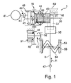
図1は、独国特許出願102013207871号に記載の従来技術によるシングルモータ型伝動機構アクチュエータを示している。モータ41により、円筒歯車歯列42が対応するモータスピンドル43を介して駆動され、両回転方向44,45が可能である。円筒歯車歯列42は、内歯車内歯列46に係合する。内歯車内歯列46は、本実施の形態では、スピンドル30(ねじ山付きスピンドル)を直接駆動する。モータ41のモータスピンドル43の回転方向次第で、スピンドル30も、第1の回転方向44又は逆向きの第2の回転方向45で回転運動を実施する。
FIG. 1 shows a single motor type transmission mechanism actuator according to the prior art described in German patent application 103013207871. The
(ねじ山付き)スピンドル30には、スピンドルナット31が配置されている。スピンドルナット31は、歯列56(図2参照)を介して2つの歯車33,34のその都度一方に係合しており、歯車33,34自体は、軸歯車35を介してシフト軸3に作用結合されている。スピンドルナット31の軸方向の調節は、2つの歯車33,34の一方の歯車の回転を引き起こす。この回転は、軸歯車35の回転と、これに応じて、シフト軸3に配置されているシフトレバー47の旋回とを引き起こす。シフトレバー47は、自動車伝動機構装置2と協働する。自動車伝動機構装置2は、複数のギヤ段を形成すべく複数の変速段を有している。シフトレバー47は、旋回運動によりシフト運動12を実施する。
A
スピンドルナット31がスピンドル30に沿って動かされると、第3の歯車49との係合が拡大する、すなわち、重なり領域が生じる。この運動によって初めて係合が生じるようにすることも可能である。その際、スピンドルナット31がねじ山付きスピンドル30の第1の軸方向の位置範囲50にあり、係止部48に係合している限り、スピンドルナット31は、係止部48の係止力に抗して軸方向で移動不能である。シフト軸3の回転、すなわち、シフト動作は、スピンドルナット31と係止部48との間の係止力が克服されるまで、スピンドルナット31がこの第1の軸方向の位置範囲50から離脱し、スピンドル30に沿って別の軸方向の範囲に進入して初めて可能となる。スピンドルナット31は、第3の歯車49を介してフリーホイール51に接続されている。フリーホイール51は、第2の回転方向45でのみ回転運動を許容するので、スピンドルナット31は、第1の回転方向44でのみ回転運動を実施可能である。フリーホイール51の回転軸線上には、セレクト歯車52も配置されており、スピンドルナット31またはモータスピンドル43の回転は、セレクト歯車52を介してセレクトポット53に伝達される。セレクトポット53も、相応して一回転方向でのみ駆動されることができ、セレクトポット53の周囲に配置される軌道カム54により、この回転運動をガイドピン55の昇降運動に変換する。ガイドピン55は、軌道カム54内に係合し、シフト軸3に結合されている。これにより、ガイドピン55の昇降運動は、シフトレバー3のセレクト運動11に相当する。このセレクト運動11は、モータ41が第1の回転方向44で動いている間、実施される。モータ41がその回転方向を変えると、セレクト運動11は、フリーホイール51に基づいて停止する。しかし、それでもスピンドル30は回転し、止められているスピンドルナット31は、スピンドル30に沿って第1の軸方向の位置範囲50に戻る。第1の軸方向の位置範囲50では、さらなる軸方向の運動が、係止部48により改めて阻止される。スピンドルナット31のこの軸方向の運動60のとき、スピンドルナット6は、歯列56を介して、改めて、シフト軸3に作用結合されている2つの歯車33,34のうちのその都度一方に係合している。これにより、スピンドルナット31の軸方向の運動を介して、シフト運動12が実施される。
As the
独国特許出願102013207871号の記載内容の全体を参照により援用する。 The entire description of German patent application 103013207871 is incorporated by reference.
モータ41の運動をスピンドル30、フリーホイール51、セレクトポット53及び軸歯車35に伝達し、ひいてはシフト軸3のセレクト運動11及びシフト運動12を引き起こす歯車対を、接続装置18という。
A gear pair that transmits the motion of the
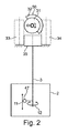
図2は、図1の要部を90°回転させた位置で示している。本図では、スピンドルナット31は、歯列56を介して第2の歯車34に係合しており、その結果、軸方向の運動60(図1参照)は、第2の歯車34の回転、ひいては軸歯車35の回転、ひいてはシフト軸3のシフト運動12を引き起こす。シフト軸3に配置されるシフトレバー47は、シフト軸3の回転時、シフト運動12を実施する。シフト運動12により自動車伝動機構装置2が操作され、これに応じて1つのギヤ段がシフトされる。
FIG. 2 shows the main part of FIG. 1 at a position rotated by 90 °. In this figure, the
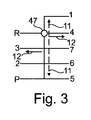
図3は、セレクト運動11及びシフト運動12を抽象化したH型シフトパターン図を示している。本図では、シフトレバー47が、後進ギヤ段または4速のギヤ段の手前に配置されており、適当にセレクト運動11を実施して、シフト運動12を実施することができる。
FIG. 3 shows an H-type shift pattern diagram in which the
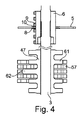
図4は、シフト軸3であって、シフト軸3上に配置されるスライダ機構4及びシフトレバー47を有するシフト軸3と、自動車伝動機構装置2のシフトレール57とを示している。シフトレバー47は、1つのシフトフィンガ62と複数のエジェクタカム61とを有している。シフトレバー47のエジェクタカム61は、「アクティブインターロック(Active Interlock)」の形態で、自動車伝動機構装置2の、本図に示すシフトレール57と相互作用可能であるように形成されている。このような「アクティブインターロック」の作用及び構造については、本件出願人による本件出願時には未公開の独国特許出願102013203284号を参照されたい。これをもって当該刊行物の記載内容の全体も参照により援用される。
FIG. 4 shows the
本図では、シフトフィンガ62は、1つのシフトレール57の直前に配置されているので、シフト軸3のシフト運動12時、1つのギヤ段を入れることができる。シフトレール57手前のシフトフィンガ62のこの位置は、スライダ機構4により設定される。このためにスライダ機構4は、突起(ランド)9と溝8とを有する第2のスライダ機構部分6を有しており、第2のスライダ機構部分6は、シフト軸3を取り巻くようにかつシフト軸3に対して同軸に配置されている。ここでは、要素10を有する第1のスライダ機構部分5が、第2のスライダ機構部分6を取り巻くように延在しており、要素10は、外側から突起9間の溝8内に係合可能である。これにより、シフト軸3のシフト運動12の際には、シフト軸3に堅固に結合される第2のスライダ機構部分6が、第1のスライダ機構部分5に対して周方向19,20で回動可能であるので、要素10が、シフト運動12の枠内で溝8内に入り込むことが可能となる。
In this figure, since the
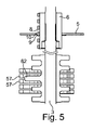
図5は、図4に示したアッセンブリを示している。本図では、シフトフィンガ62が、2つの隣接するシフトレール57の手前に配置されており、シフト運動12時、2つのギヤ段が同時に入れられてしまう虞がある。しかし、このシフト運動12は、シフト運動12の際に要素10が突起9に衝突するため、スライダ機構4によって阻止される。
FIG. 5 shows the assembly shown in FIG. In this figure, the
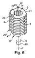
図6は、第1の実施変化形態による第2のスライダ機構部分6を示している。第2のスライダ機構部分6は、方向7,22で交互に溝8及び突起9を有している。第2のスライダ機構部分6は、内周面24に第1の輪郭歯列23を有している。第1の輪郭歯列23には、第2のスライダ機構部分6及びシフト軸3(本図には図示せず)相互の1つの組み付け位置のみを許容するコーディング歯27が設けられている。さらにマーキング29が第2のスライダ機構部分6に配置されており、シフト軸3に対する第2のスライダ機構部分6の組み付け位置28が看取可能であるようになっている。これにより、第2のスライダ機構部分6の組み立てが簡単になり、シフト軸3に対する間違った配置が回避される。第2のスライダ機構部分6は、互いに反対側に位置する2つのゲート21を有しており、各ゲート21の両側26に複数の溝9及び複数の突起8を有している。これにより、シフト運動12を、第1の周方向19と第2の周方向20とで実施可能である。
FIG. 6 shows a second
本図で看取可能であるように、図示の第2のスライダ機構部分6の場合、別のゲート21が反対側に配置されている。これにより、第2のスライダ機構部分6は(例えば2つのコーティング歯27が存在する場合)、180°回転されて、場合によっては、180°裏返されて組み立てられてもよい。
As can be seen in this figure, in the case of the illustrated second
図7は、図6に示した第2のスライダ機構部分6と第1のスライダ機構部分5との協働を示している。第1のスライダ機構部分5は、可動のシフト軸3に対してハウジング固定に組み立てられている。第2のスライダ機構部分6は、シフト軸3に配置されており、シフト軸3とともにギヤ段のセレクトのために軸方向で移動可能であり、ギヤ段のシフトのために回転可動である。第1のスライダ機構部分5は、複数の要素10を有している。複数の要素10のそれぞれは、複数の突起9のそれぞれ1つと協働可能であるとともに、複数の溝8のそれぞれ1つに進入可能である。セレクト運動11のとき、要素10は、ゲート21内に配置されており、突起8及び溝9の傍らを通過可能である。シフト運動12のとき、要素10は、溝9の1つに進入可能である。突起8は、シフトフィンガ62が自動車伝動機構装置2内で正しく位置決めされていないときに、シフト運動12が実施されてしまわないようにする。このために、第1のスライダ機構部分5に対する自動車伝動機構装置2の位置または第2のスライダ機構部分6及びシフト軸3に対する自動車伝動機構装置2の位置は、正確に調整されていなければならない。
FIG. 7 shows the cooperation of the second
スライダ機構4は、而るに、図8〜11に略示する以下の機能を有している。1つには、スライダ機構4は、1つのギヤ段が入れられている間のセレクト運動11を阻止する(例えば図9参照)。さらにスライダ機構4は、2つのギヤ段が同時に入れられてしまわないようにする(例えば図11参照)。さらにスライダ機構4は、例えば溝8からゲート21内に戻る際のトルクサポートとしても用いられる。スライダ機構4なしには、シフトフィンガ62がセレクト運動11を実施すべきか、又はシフト運動12を実施すべきか、帰路が規定されない。遮断(要素10が突起9に突き当たったとき)は、制御部38によりセンサを介して検出可能であり、その結果、シフト軸3、ひいては第2のスライダ機構部分6の実際位置39を特定可能である。求められた実際位置39から出発して、目標位置40に正確に到達可能である(セレクト運動11、シフト運動12)。
Thus, the slider mechanism 4 has the following functions schematically shown in FIGS. For example, the slider mechanism 4 prevents the
さらにスライダ機構4は、シフト運動に関わる要素、例えばシフトフィンガの、より大きな製造公差が許容されることを可能にする。その結果、これらの要素相互のより大きなエラー位置も補償可能であり、シフト動作を試みて失敗する回数が減少し、同時に接続装置18の歪みが回避される。すなわち、まさにシングルモータ型伝動機構アクチュエータ1の場合、フリーホイール51のロックされた回転方向で作用するシフト軸3の運動が引き起こされるか又は強制されることは、回避すべきである。
Furthermore, the slider mechanism 4 allows a larger manufacturing tolerance of elements involved in the shift movement, for example shift fingers, to be tolerated. As a result, larger error positions between these elements can also be compensated, reducing the number of failed attempts to shift and at the same time avoiding distortion of the connecting
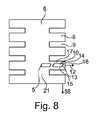
図8は、第2のスライダ機構部分6のゲート21、溝8及び突起9と、第1のスライダ機構部分5の要素10とを示している。要素10と溝8との協働は、図3に示した抽象的なシフトパターン図に対応している。本図では、第1のスライダ機構部分5の要素10は、第2のスライダ機構部分6の溝8内にある。このことは、1つのギヤ段がシフトフィンガ62のシフト運動12により自動車伝動機構装置2内で入れられていることを意味する。要素10は、端壁16と、端壁16と第1の壁15との間に設けられた導入面取り部13とを有している。第1の壁15は、セレクト運動11の決まった方向58を向いている。
FIG. 8 shows the
図9は、第1のスライダ機構部分5及び第2のスライダ機構部分6相互の別の配置でスライダ機構4を示している。本図では、要素10は、溝9内で突起8と接触している。これにより、セレクト運動11に沿った方向7,22での突起8及び/又は要素10の実際位置39を特定可能である。この実際位置39は、制御部38内の目標位置40と照合可能であるので、伝動機構アクチュエータ1の摩耗も特定可能である。セレクト運動11のとき、第2のスライダ機構部分6は、固定の第1のスライダ機構部分5に対して、決まった方向58に沿って動かされる。
FIG. 9 shows the slider mechanism 4 in another arrangement with respect to the first
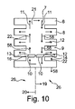
図10は、可動の第2のスライダ機構部分6と固定の第1のスライダ機構部分5とを有するスライダ機構4のセレクト運動11及びシフト運動12のすべてを示している。第2のスライダ機構部分6は、スライダ機構部分5に対して軸方向で移動可能かつ回転可動に配置可能であり、本図では、第2のスライダ機構部分6は、方向7,22に沿って交互に溝8及び突起9を有している。さらに第2のスライダ機構部分6は、ゲート21の両側26に溝9及び突起8を有しており、その結果、決まった方向58でのゲート21内のセレクト運動11から出発して、シフト運動12をその都度一方の周方向19,20でのみ実施可能である。
FIG. 10 shows all of the
溝9及び突起8は、而るに、セレクト運動11のとき、決まった方向58に沿って要素10の傍らを通過し、その後、シフト運動12のとき、第2のスライダ機構部分6は、一方の周方向19,20で要素10に対して旋回され、要素10は、溝9の1つに進入可能である。要素10の図示の位置において、シフト運動12が実施されると、右側の要素10は、導入面取り部13を介して第2のスライダ機構部分6をセレクト運動11の決まった方向58に沿ってさらに移動させることができ、溝8に合致し、要素10は、溝8内に挿入され得る。これにより、シフトフィンガ62も、正しく位置決めされるので、場合によっては、シフトフィンガ62及び/又は溝8のエラー位置が補償され、ひいては、ギヤ段のシフトのために利用可能なウインドウが拡大する。なお、シフト運動12が周方向20で実施される場合は、左側の要素10が、ゲート21の他方の側26の溝9及び突起8と協働する。
Thus, the
図11は、図8に則した図であり、本図では、エラーのあるシフト運動12が停止される。要素10を有する第1のスライダ機構部分5と、溝9及び突起8を有する第2のスライダ機構部分6との、本図に示した配置では、要素10の端面16が突起8に衝突するので、シフト運動12は不可能である。ここには導入面取り部13が存在しないため、第2のスライダ機構部分6は、決まった方向58とは逆向きの方向に動くことができず、その結果、シフト運動12、同時に接続装置18の歪みは、ここでは阻止される。
FIG. 11 is a diagram according to FIG. 8, and in this figure, the
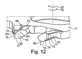
図12は、2つの要素10を有する第1のスライダ機構部分5を示している。両要素10は、ともに第2のスライダ機構部分6(例えば図4〜11)の1つのゲート21内に配置可能である。要素10は、セレクト運動11の決まった方向58にそれぞれ第1の壁16と、決まった方向58とは逆向きの方向に第2の壁17とを有している。第2の壁17と端壁16との間には、それぞれ直角の移行部14が設けられており、端壁16と第1の壁15との間には、それぞれ導入面取り部13が設けられている。導入面取り部13を介して、第2のスライダ機構部分6は、セレクト運動11の決まった方向58でさらに移動可能であり、セレクト運動11から出発して、その都度一方の周方向19,20でのみシフト運動12を実施可能である。
FIG. 12 shows a first
つまり、導入面取り部13は、決まった方向58に対して90度より小さい、特に50〜70度の角度63を有している。この場合、導入面取り部13は、シフト運動12の方向(本図では周方向20)に長さ65を有しており、その結果、第2のスライダ機構部分6は、導入面取り部13の長さ65にわたって、区間64の分だけ決まった方向58でさらに移動可能である。この説明は、第2のスライダ機構部分6に導入面取り部13を設けた場合(又は図14及び15に示す第2の実施変化形態によるスライダ機構4)にも相応に当てはまる。
That is, the
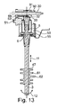
図13は、シングルモータ型伝動機構アクチュエータを側方から見た断面図で示している。図1に関連して既に説明したように、本図には示さないモータ41を介してスピンドル30が駆動され、スピンドルナット31と第3の歯車49とを介して、フリーホイール51に配置されるセレクト歯車52が駆動される。セレクト歯車52は、セレクトポット53を回転させるように設けられている。セレクトポット53内には、軌道カム54が延びており、軌道カム54は、ガイドピン55と協働し、セレクトポット53の回転時に、ガイドピン55を介してセレクトポット53に作用結合されているシフト軸3が、セレクト運動11を実施するようにする。シフト軸3には、シフトフィンガ62とエジェクタカム61とを有するシフトレバー47が配置されている。スピンドル30を介してねじ山付きスピンドル31は、軸方向の運動60を実施可能であり、その結果、ラック32として構成されるスピンドルナット31を介して、歯車33,34は回動され得る。歯車33,34は、相対回動不能にシフト軸3に結合されている軸歯車35に作用結合されている。つまり、スピンドルナット31の軸方向の運動60を介して、シフト運動12が実施される。このとき、第1のスライダ機構部分5は、シフト軸3に関して半径方向外側に配置されるポットを介して提供される一方、第2のスライダ機構部分6は、シフト軸3の構成部分である。特に第2のスライダ機構部分6は、シフト軸3の変形加工法又はフライス加工によりシフト軸3自体から製造されてもよい。
FIG. 13 is a sectional view of a single motor type transmission mechanism actuator as viewed from the side. As already described in connection with FIG. 1, the
図14は、スライダ機構4の第2の実施変化形態を含むシングルモータ型伝動機構アクチュエータ1の要部斜視図である。図1の説明を参照されたい。同じ符号は、同じ対象を指している。伝動機構アクチュエータ1は、本形態では、スピンドルナット31を有するスピンドル30を有しており、スピンドルナット31は、ラック32を形成し、2つの歯車33,34のその都度一方を介して軸歯車35に作用結合されており、軸歯車35は、シフト軸3に堅固に結合されている。
FIG. 14 is a perspective view of a main part of the single motor type
本形態では、スピンドルナット31が第2のスライダ機構部分6を形成している。溝9及び突起8は、スピンドル軸線36に対して平行に延びており、第1のスライダ機構部分5の要素10は、少なくとも1つのピン37(本形態では、互いに平行にかつスピンドル軸線36の互いに反対側に配置されている2つのピン)により形成されている。
In this embodiment, the
図15は、図14に示したシングルモータ型伝動機構アクチュエータの要部を、スピンドル軸線36に沿って見た図である。セレクト運動11時、第2のスライダ機構部分6は、第1のスライダ機構部分4の固定のピン37に対して、決まった方向58で回転される。シフト運動12時、スピンドルナットは、スピンドル軸線36に沿った軸方向の運動60を実施する。ピン37は、位置が合致したとき、第2のスライダ機構部分6の溝9内に係合し、シフト運動12を可能にする。本形態でも、端面16から第1の壁15への移行部14に設けられた導入面取り部13は、ピン37と突起8とが衝突したとき、決まった方向58で第2のスライダ機構部分6を移動させることを可能にする。逆向きの方向での移動は、端面16と第2の壁15との間の直角の移行部14により阻止される。
FIG. 15 is a view of the main part of the single motor type transmission mechanism actuator shown in FIG. 14 as viewed along the
上述の構造に関わらず、もちろん、上述の伝動機構アクチュエータの作用原理を反転させることが可能である。その際、スライダ機構レールを位置固定に取り付けることは、当業者とって容易に可能である。このスライダ機構レールは、上述のスライダ機構4に相当するが、この場合、このスライダ機構4に対して実質的に相補的に、すなわち、とりわけ内部中空に構成されている。このスライダ機構レールは、ハウジング固定となり、シフト軸3に相対回動不能に配置される要素10のための溝8を提供することになる。第1のスライダ機構部分は、相応して第1のスライダ機構部分6に対して相補的に構成され、シフト軸3に結合される。
Regardless of the structure described above, it is of course possible to reverse the operating principle of the above-described transmission mechanism actuator. At that time, it is possible for those skilled in the art to easily attach the slider mechanism rail to the fixed position. The slider mechanism rail corresponds to the above-described slider mechanism 4, but in this case, is configured to be substantially complementary to the slider mechanism 4, i.e., particularly hollow inside. This slider mechanism rail is fixed to the housing, and provides a
1 伝動機構アクチュエータ
2 自動車伝動機構装置
3 シフト軸
4 スライダ機構
5 第1のスライダ機構部分
6 第2のスライダ機構部分
7 第1の方向
8 溝
9 突起
10 要素
11 セレクト運動
12 シフト運動
13 導入面取り部
14 移行部
15 第1の壁
16 端面
17 第2の壁
18 接続装置
19 第1の周方向
20 第2の周方向
21 ゲート
22 第2の方向
23 第1の輪郭歯列
24 内周面
25 溝
26 側
27 コーディング歯
28 組み付け位置
29 マーキング
30 スピンドル
31 スピンドルナット
32 ラック
33 第1の歯車
34 第2の歯車
35 軸歯車
36 スピンドル軸線
37 ピン
38 制御部
39 実際位置
40 目標位置
41 モータ
42 円筒歯車歯列
43 モータスピンドル
44 第1の回転方向
45 第2の回転方向
46 内歯車内歯列
47 シフトレバー
48 係止部
49 第3の歯車
50 第1の軸方向の位置範囲
51 フリーホイール
52 セレクト歯車
53 セレクトポット
54 軌道カム
55 ガイドピン
56 歯列
57 シフトレール
58 決まった方向
59 外周面
60 軸方向の運動
61 エジェクタカム
62 シフトフィンガ
63 角度
64 区間
65 長さ
DESCRIPTION OF
Claims (12)
前記伝動機構アクチュエータ(1)は、シフト軸(3)を備え、前記シフト軸(3)は、前記ギヤ段のシフトのために回転可動に支持されており、前記ギヤ段のセレクトのために軸方向で移動可能に支持されており、前記伝動機構アクチュエータ(1)は、スライダ機構(4)を備え、前記スライダ機構(4)は、固定に配置される第1のスライダ機構部分(5)と、軸方向で移動可能かつ回転可動の第2のスライダ機構部分(6)とを有し、両前記スライダ機構部分の一方のスライダ機構部分(5,6)は、一方向(7,22)に沿って交互に溝(8)と突起(9)とを有し、他方のスライダ機構部分(6,5)は、前記突起(9)のそれぞれ1つと協働可能かつ前記溝(8)のそれぞれ1つに進入可能である少なくとも1つの要素(10)を有し、前記少なくとも1つの要素(10)は、決まった方向(58)でのセレクト運動(11)のとき、前記突起(9)及び前記溝(8)の傍らを通過し、シフト運動(12)のとき、前記溝(8)の1つに進入し、
少なくとも前記突起(9)又は前記要素(10)に導入面取り部(13)が設けられており、前記第2のスライダ機構部分(6)は、シフト運動(12)中の前記要素(10)と前記突起(9)との間の衝突時、前記導入面取り部(13)を介してセレクト運動(11)の前記決まった方向(58)でさらに可動であり、シフト運動(12)は続行可能であり、他方、略直角の移行部(14)が設けられており、シフト運動(12)中の前記要素(10)と前記突起(9)との間の衝突時、前記第2のスライダ機構部分(6)は、セレクト運動(11)の前記決まった方向(58)とは逆方向に不動であり、シフト運動(12)は停止される、伝動機構アクチュエータ(1)において、
前記要素(10)は、前記決まった方向(58)を向いている第1の壁(15)と、前記溝(8)に向かう端面(16)とを有し、前記端面(16)と前記第1の壁(15)との間に前記導入面取り部(13)が存在し、前記要素(10)は、前記決まった方向(58)とは逆向きの第2の壁(17)を有し、前記端面(16)と前記第2の壁(17)との間に前記略直角の移行部(14)が存在することを特徴とする、伝動機構アクチュエータ(1)。 A transmission mechanism actuator (1) for an automotive transmission mechanism device (2) having a plurality of shift stages to form a plurality of gear stages,
The transmission mechanism actuator (1) includes a shift shaft (3), and the shift shaft (3) is rotatably supported for shifting the gear stage, and a shaft for selecting the gear stage. The transmission mechanism actuator (1) includes a slider mechanism (4), and the slider mechanism (4) includes a first slider mechanism portion (5) fixedly disposed. A second slider mechanism portion (6) that is movable in the axial direction and is rotatable, and one slider mechanism portion (5, 6) of both the slider mechanism portions is in one direction (7, 22). Alternately having grooves (8) and protrusions (9), and the other slider mechanism portion (6, 5) can cooperate with each one of the protrusions (9) and each of the grooves (8). At least one element (10 Wherein said at least one element (10), when the select motion (11) in the fixed direction (58), passes through the side of the projection (9) and the groove (8), a shift motion ( 12) enter one of the grooves ( 8 ) ,
At least the protrusion ( 9 ) or the element (10) is provided with an introduction chamfer (13), and the second slider mechanism part (6) is connected to the element (10) in a shift motion (12). At the time of collision with the protrusion ( 9 ), it is further movable in the determined direction (58) of the select movement (11) via the introduction chamfer (13), and the shift movement (12) can be continued. On the other hand, a substantially right-angled transition (14) is provided, the second slider mechanism part in the event of a collision between the element (10) and the projection ( 9 ) during a shift movement (12) (6) In the transmission mechanism actuator (1), the select movement (11) is stationary in the direction opposite to the fixed direction (58), and the shift movement (12) is stopped .
The element (10) has a first wall (15) facing the fixed direction (58) and an end face (16) towards the groove (8), the end face (16) and the The introduction chamfer (13) is present between the first wall (15) and the element (10) has a second wall (17) opposite to the fixed direction (58). The transmission mechanism actuator (1) is characterized in that the substantially perpendicular transition portion (14) exists between the end face (16) and the second wall (17 ).
a.シフト運動(12)を実施し、前記少なくとも1つの要素(10)を前記溝(8)内に配置するステップと、
b.セレクト運動(11)を実施し、前記要素(10)と前記突起(9)とを互いに接触させるステップと、
c.前記突起(9)及び/又は前記要素(10)の、セレクト運動(11)の方向(7,22)での実際位置(39)を特定するステップと、
d.目標位置(40)と前記実際位置(39)とを前記制御部(38)内で照合し、前記伝動機構アクチュエータ(1)の摩耗を特定するステップと、
を含むことを特徴とする方法。 A method for selecting and shifting a gear stage using the transmission mechanism actuator (1) according to any one of claims 1 to 11, wherein a control unit (38) is provided,
a. Performing a shift movement (12) and placing the at least one element (10) in the groove ( 8 );
b. Performing a select movement (11), bringing the element (10) and the protrusion ( 9 ) into contact with each other;
c. Identifying the actual position (39) of the projection ( 9 ) and / or the element (10) in the direction (7, 22) of the select movement (11);
d. Collating the target position (40) and the actual position (39) in the control unit (38) to identify the wear of the transmission mechanism actuator (1);
A method comprising the steps of:
Applications Claiming Priority (3)
| Application Number | Priority Date | Filing Date | Title |
|---|---|---|---|
| DE102014205659.4 | 2014-03-26 | ||
| DE102014205659 | 2014-03-26 | ||
| PCT/DE2015/200100 WO2015144153A1 (en) | 2014-03-26 | 2015-02-24 | Single-motor transmission actuator comprising a gate for selecting and shifting gears of a motor vehicle transmission device |
Publications (2)
| Publication Number | Publication Date |
|---|---|
| JP2017512951A JP2017512951A (en) | 2017-05-25 |
| JP6559155B2 true JP6559155B2 (en) | 2019-08-14 |
Family
ID=52697178
Family Applications (4)
| Application Number | Title | Priority Date | Filing Date |
|---|---|---|---|
| JP2016559177A Expired - Fee Related JP6509250B2 (en) | 2014-03-26 | 2015-02-24 | Transmission actuator for automobile transmission |
| JP2016559338A Expired - Fee Related JP6509251B2 (en) | 2014-03-26 | 2015-02-24 | Transmission actuator for automobile transmission |
| JP2016559204A Expired - Fee Related JP6559156B2 (en) | 2014-03-26 | 2015-02-24 | Cam transmission mechanism for shift shaft operation |
| JP2016559194A Expired - Fee Related JP6559155B2 (en) | 2014-03-26 | 2015-02-24 | Single motor type transmission mechanism actuator with slider mechanism that selects and shifts gear stage of automobile transmission mechanism device |
Family Applications Before (3)
| Application Number | Title | Priority Date | Filing Date |
|---|---|---|---|
| JP2016559177A Expired - Fee Related JP6509250B2 (en) | 2014-03-26 | 2015-02-24 | Transmission actuator for automobile transmission |
| JP2016559338A Expired - Fee Related JP6509251B2 (en) | 2014-03-26 | 2015-02-24 | Transmission actuator for automobile transmission |
| JP2016559204A Expired - Fee Related JP6559156B2 (en) | 2014-03-26 | 2015-02-24 | Cam transmission mechanism for shift shaft operation |
Country Status (7)
| Country | Link |
|---|---|
| US (2) | US10260626B2 (en) |
| EP (3) | EP3123062B1 (en) |
| JP (4) | JP6509250B2 (en) |
| KR (4) | KR20160137549A (en) |
| CN (5) | CN106104100B (en) |
| DE (5) | DE112015001417A5 (en) |
| WO (5) | WO2015144148A1 (en) |
Families Citing this family (18)
| Publication number | Priority date | Publication date | Assignee | Title |
|---|---|---|---|---|
| DE102015201352A1 (en) | 2015-01-27 | 2016-07-28 | Schaeffler Technologies AG & Co. KG | Single-motor gearbox actuator with independent freewheel |
| CN106286794B (en) * | 2015-06-02 | 2019-02-15 | 上海汽车集团股份有限公司 | A vehicle transmission gear selection and shifting device |
| DE102016219322A1 (en) | 2016-10-06 | 2018-04-12 | Schaeffler Technologies AG & Co. KG | Hydraulic gear actuator |
| CN106481802B (en) * | 2016-12-05 | 2018-11-20 | 广州汽车集团股份有限公司 | shift actuator |
| DE102016125096B4 (en) * | 2016-12-21 | 2019-09-19 | Schaeffler Technologies AG & Co. KG | Drive train with actuator for connecting an electrical machine to a rotating part of the drive train |
| DE102017204119A1 (en) * | 2017-03-13 | 2018-09-13 | Robert Bosch Gmbh | Actuator with a drive unit and a gear unit |
| DE102017204114A1 (en) * | 2017-03-13 | 2018-09-13 | Robert Bosch Gmbh | Drive unit for an actuator, as well as actuator with a drive unit and a gear unit |
| US20200014284A1 (en) * | 2017-03-31 | 2020-01-09 | Nidec Tosok Corporation | Electric actuator |
| CN106958642B (en) * | 2017-05-02 | 2023-05-02 | 苏州江南嘉捷光机电技术有限公司 | Two-gear automatic gearbox of electric automobile |
| DE102018216742A1 (en) | 2018-09-28 | 2020-04-02 | Knorr-Bremse Systeme für Nutzfahrzeuge GmbH | Connection between a switching element and an aisle selector rod |
| DE102019220181B3 (en) * | 2019-12-19 | 2021-06-02 | Magna Pt B.V. & Co. Kg | Shift drum arrangement for a shifting device of a transmission arrangement |
| DE102020105685A1 (en) * | 2020-03-03 | 2021-09-09 | HELLA GmbH & Co. KGaA | Device comprising an electronics housing and a functional housing |
| DE102020107596A1 (en) | 2020-03-19 | 2021-09-23 | Nidec Corporation | Gear housing arrangement with a freewheel for mounting a motor shaft |
| DE102020107597B4 (en) | 2020-03-19 | 2024-03-21 | Nidec Corporation | Actuator of a motor vehicle automatic transmission |
| CN111677859B (en) * | 2020-06-28 | 2025-02-11 | 浙江科博达工业有限公司 | Select shift actuator |
| DE102020123965B4 (en) * | 2020-09-15 | 2022-12-22 | Schaeffler Technologies AG & Co. KG | Spindle drive arrangement, steering unit and landing gear actuator |
| EP4461996A1 (en) * | 2023-05-09 | 2024-11-13 | ArvinMeritor Technology, LLC | Modular shifting system |
| DE102023113811A1 (en) | 2023-05-25 | 2024-11-28 | Daimler Truck AG | Switching device for an at least partially electrically operated motor vehicle |
Family Cites Families (66)
| Publication number | Priority date | Publication date | Assignee | Title |
|---|---|---|---|---|
| FR2212772A5 (en) | 1972-12-29 | 1974-07-26 | Bettiol Bruno | |
| JP3053254B2 (en) * | 1991-05-17 | 2000-06-19 | 三信工業株式会社 | Engine ignition timing adjustment device |
| DE4137142A1 (en) * | 1991-11-12 | 1993-05-13 | Zahnradfabrik Friedrichshafen | SWITCHING DEVICE FOR OEDIE SWITCHING ACTUATION OF MULTI-STAGE GEARBOXES FOR MOTOR VEHICLES |
| FR2698945B1 (en) * | 1992-12-07 | 1995-01-06 | Valeo Systemes Dessuyage | Mechanical transmission member of the type comprising a shaft and a toothed wheel and wiper motor comprising such a mechanical member. |
| US5740695A (en) * | 1996-01-29 | 1998-04-21 | Ford Global Technologies, Inc. | Shift device for a manual transmission |
| IT1289758B1 (en) * | 1996-12-17 | 1998-10-16 | Magneti Marelli Spa | COMMAND DEVICE FOR A VEHICLE SPEED CHANGE. |
| FR2774447B1 (en) * | 1998-02-03 | 2005-03-04 | Luk Getriebe Systeme Gmbh | VEHICLE EQUIPPED WITH AN AUTOMATED MANEUVER DEVICE FOR A GEARBOX |
| EP1450022B1 (en) * | 1999-03-29 | 2007-07-18 | Hitachi, Ltd. | Motor driving type trhottle apparatus |
| IT1311099B1 (en) * | 1999-10-18 | 2002-02-28 | Magneti Marelli Spa | CONTROL UNIT OF THE SELECTION SHAFT AND GEAR OF THE GEARS OF A SPEED CHANGE. |
| US6155126A (en) * | 1999-10-18 | 2000-12-05 | Borgwarner Inc. | Integrated shift motor and electronic controller |
| CN1115267C (en) * | 2000-03-10 | 2003-07-23 | 赵济威 | Executor for full-automatic speed variation of car |
| DE10045729C2 (en) * | 2000-09-15 | 2003-07-17 | Zf Sachs Ag | setting device |
| DE10134937A1 (en) * | 2001-07-18 | 2003-02-06 | Bosch Gmbh Robert | Gear drive unit with speed detection |
| JP3799270B2 (en) * | 2001-12-21 | 2006-07-19 | 株式会社日立製作所 | Control device for switching the driving state of an automobile |
| US20030125150A1 (en) * | 2001-12-28 | 2003-07-03 | Visteon Global Technologies, Inc. | Enhanced shift couplers for shift-on-the-go transmission |
| JPWO2004068679A1 (en) * | 2003-01-27 | 2006-05-25 | 株式会社日立製作所 | Electric motor unit with controller |
| JP4449476B2 (en) * | 2003-03-31 | 2010-04-14 | いすゞ自動車株式会社 | Shift actuator for transmission |
| FR2853373B1 (en) * | 2003-04-02 | 2006-03-03 | Hutchinson | DECOUPLING ELEMENT OF DEFORMABLE MATERIAL IN A POWER TRANSMISSION SYSTEM |
| DE102004038955A1 (en) * | 2003-08-16 | 2005-03-10 | Luk Lamellen & Kupplungsbau | Actuator, especially for shifting gearbox, has bidirectionally driven drive shaft, control device with thread profile complementary to drive shaft profile, control element rotating with control device |
| JP2005113956A (en) * | 2003-10-03 | 2005-04-28 | Bosch Automotive Systems Corp | Motor driven transmission operating device |
| TWI242506B (en) * | 2003-12-30 | 2005-11-01 | Ind Tech Res Inst | Automatic gear device |
| JP2005351387A (en) * | 2004-06-10 | 2005-12-22 | Toyota Motor Corp | Shift gate mechanism of manually operated transmission |
| JP2006029507A (en) * | 2004-07-20 | 2006-02-02 | Toyota Motor Corp | Shift gate mechanism of manual transmission |
| DE102004036369B4 (en) * | 2004-07-27 | 2007-12-13 | Selzer Fertigungstechnik Gmbh & Co. Kg | Control drum arrangement for a motor vehicle change gearbox |
| DE102004039068B4 (en) * | 2004-08-12 | 2014-03-13 | Zf Friedrichshafen Ag | Actuator for an automated multi-stage manual transmission of a motor vehicle |
| JP4587066B2 (en) * | 2004-11-10 | 2010-11-24 | マツダ株式会社 | transmission |
| DE102006017158B4 (en) | 2005-05-07 | 2022-04-21 | Schaeffler Technologies AG & Co. KG | Transmission actuator for a motor vehicle transmission device, motor vehicle transmission device with a transmission actuator and motor vehicle drive train with a motor vehicle transmission device |
| JP2007024150A (en) * | 2005-07-14 | 2007-02-01 | Aisin Ai Co Ltd | Shift device for transmission |
| JP2007056994A (en) * | 2005-08-24 | 2007-03-08 | Aisin Ai Co Ltd | Shift device of transmission |
| DE102006054907A1 (en) * | 2005-12-15 | 2007-06-28 | Luk Lamellen Und Kupplungsbau Beteiligungs Kg | Actuator for a vehicle transmission comprises a first axially moving steering rack and a second axially moving steering rack connected to a spindle nut |
| DE102006054902A1 (en) * | 2005-12-15 | 2007-06-28 | Luk Lamellen Und Kupplungsbau Beteiligungs Kg | Gear actuator for a motor vehicle's gearing device has an electric motor, a rotating threaded spindle driven by this motor, a spindle nut driven by the threaded spindle and a gear selector shaft |
| DE102006054901A1 (en) | 2005-12-15 | 2007-06-28 | Luk Lamellen Und Kupplungsbau Beteiligungs Kg | Vehicle gearbox gear actuator, with an electromotor for a threaded spindle and spindle nut, has meshing cogwheels and racks at the selection shaft coupled to the nut and spindle |
| DE102006054906A1 (en) * | 2005-12-15 | 2007-06-28 | Luk Lamellen Und Kupplungsbau Beteiligungs Kg | Actuator for vehicle transmission has threaded spindle including right hand thread and left hand thread, and one spindle nut thread for each of these |
| US7845249B2 (en) * | 2006-09-08 | 2010-12-07 | Schaeffler Technologies Gmbh & Co. Kg | Single motor transmission shifting mechanism for a motor vehicle transmission |
| JP4499083B2 (en) * | 2006-11-30 | 2010-07-07 | 本田技研工業株式会社 | Engine equipped with variable speed actuator |
| US9043100B2 (en) * | 2007-08-17 | 2015-05-26 | Steering Solutions Ip Holding Corporation | Transmission shift assembly for a vehicle and a method of monitoring the same |
| JP2009180249A (en) * | 2008-01-29 | 2009-08-13 | Toyota Motor Corp | Shift operation device and transmission |
| JP5287472B2 (en) * | 2009-04-24 | 2013-09-11 | 株式会社デンソー | Engine starter |
| DE102009002661A1 (en) * | 2009-04-27 | 2010-10-28 | Fzgmbh | Device for actuating a wengistens switchable between three switching positions interlocking switching element |
| CN201385576Y (en) * | 2009-04-30 | 2010-01-20 | 南京奥联汽车电子电器有限公司 | Manual/automatic integrated AT gear-shifting execution mechanism |
| DE102009024099A1 (en) * | 2009-06-06 | 2010-12-09 | Dr. Ing. H.C. F. Porsche Aktiengesellschaft | Switching device for a multi-stage manual transmission |
| KR101181073B1 (en) * | 2009-07-28 | 2012-09-07 | 현대자동차주식회사 | Clutch Actuating Apparatus for Double Clutch Transmission |
| JP5440862B2 (en) * | 2009-09-01 | 2014-03-12 | 株式会社ジェイテクト | Transmission |
| US8011201B2 (en) * | 2009-09-30 | 2011-09-06 | Thermo Fisher Scientific (Asheville) Llc | Refrigeration system mounted within a deck |
| DE102009048876A1 (en) * | 2009-10-09 | 2011-04-14 | Schaeffler Technologies Gmbh & Co. Kg | switching device |
| JP5234293B2 (en) * | 2010-03-02 | 2013-07-10 | 三菱自動車工業株式会社 | Transmission |
| JP5543816B2 (en) * | 2010-03-24 | 2014-07-09 | アイシン・エーアイ株式会社 | Transmission shift and select shaft assembly |
| JP5543815B2 (en) * | 2010-03-24 | 2014-07-09 | アイシン・エーアイ株式会社 | Transmission shift and select shaft assembly |
| AT510037B1 (en) * | 2010-07-26 | 2012-01-15 | Stiwa Holding Gmbh | MULTI-PIECE ROCKING SLEEVE AND METHOD FOR THE PRODUCTION THEREOF |
| AT509999B1 (en) * | 2010-09-08 | 2012-01-15 | Stiwa Holding Gmbh | CIRCUIT ARRANGEMENT AND A GEAR GEAR GEARBOX EQUIPPED THEREFOR |
| KR101251503B1 (en) * | 2010-12-01 | 2013-04-05 | 현대자동차주식회사 | Shifting apparatus for manual transmission |
| DE102010055406A1 (en) * | 2010-12-21 | 2012-06-21 | Schaeffler Technologies Gmbh & Co. Kg | switching unit |
| CN102174959A (en) * | 2011-02-24 | 2011-09-07 | 上海汽车变速器有限公司 | Transmission gearshif mechanism |
| KR101799772B1 (en) * | 2011-04-29 | 2017-11-21 | 레이저 (아시아-퍼시픽) 피티이 엘티디 | A speaker mechanism and a method for translating rotary torque into linear motion |
| US8556772B2 (en) * | 2011-05-27 | 2013-10-15 | GM Global Technology Operations LLC | Manual transmission clutch protection apparatus |
| CN102230530B (en) * | 2011-06-20 | 2014-01-22 | 奇瑞汽车股份有限公司 | Alveolus automatic gear shift operating mechanism |
| CN102506159B (en) * | 2011-10-20 | 2014-08-13 | 上海汽车变速器有限公司 | Gear selection and shift system for gear box |
| JP2013100857A (en) * | 2011-11-08 | 2013-05-23 | Jtekt Corp | Transmission actuating device |
| CN202349182U (en) * | 2011-11-22 | 2012-07-25 | 河南科技大学 | Cam type gear selection and shifting mechanism |
| DE102012100870B4 (en) * | 2011-12-29 | 2014-07-31 | Getrag Ford Transmissions Gmbh | Switching device for a manual transmission |
| JP2013245809A (en) * | 2012-05-29 | 2013-12-09 | Jtekt Corp | Electric actuator |
| JP5966742B2 (en) * | 2012-08-03 | 2016-08-10 | スズキ株式会社 | Manual transmission shift device |
| JP2014054160A (en) * | 2012-08-08 | 2014-03-20 | Jtekt Corp | Electric actuator |
| CN103016711B (en) * | 2012-12-25 | 2016-04-20 | 长城汽车股份有限公司 | A kind of shift-selecting and changing actuating mechanism and automatic transmission |
| CN203162126U (en) * | 2013-01-09 | 2013-08-28 | 上海海能汽车电子有限公司 | Electric lead screw driving mechanism of automatic transmission |
| DE102013207871A1 (en) | 2013-04-30 | 2014-10-30 | Schaeffler Technologies Gmbh & Co. Kg | Transmission actuator for a motor vehicle transmission and control for controlling a gear actuator |
-
2015
- 2015-02-24 CN CN201580015409.3A patent/CN106104100B/en not_active Expired - Fee Related
- 2015-02-24 KR KR1020167026442A patent/KR20160137549A/en not_active Withdrawn
- 2015-02-24 JP JP2016559177A patent/JP6509250B2/en not_active Expired - Fee Related
- 2015-02-24 WO PCT/DE2015/200095 patent/WO2015144148A1/en not_active Ceased
- 2015-02-24 WO PCT/DE2015/200094 patent/WO2015144147A1/en not_active Ceased
- 2015-02-24 KR KR1020167026418A patent/KR20160137548A/en not_active Withdrawn
- 2015-02-24 KR KR1020167025959A patent/KR102249031B1/en not_active Expired - Fee Related
- 2015-02-24 DE DE112015001417.9T patent/DE112015001417A5/en not_active Withdrawn
- 2015-02-24 KR KR1020167025958A patent/KR102247256B1/en not_active Expired - Fee Related
- 2015-02-24 JP JP2016559338A patent/JP6509251B2/en not_active Expired - Fee Related
- 2015-02-24 US US15/127,110 patent/US10260626B2/en not_active Expired - Fee Related
- 2015-02-24 WO PCT/DE2015/200100 patent/WO2015144153A1/en not_active Ceased
- 2015-02-24 EP EP15713836.3A patent/EP3123062B1/en active Active
- 2015-02-24 CN CN201580015410.6A patent/CN106133403B/en not_active Expired - Fee Related
- 2015-02-24 CN CN201580015400.2A patent/CN106133408B/en not_active Expired - Fee Related
- 2015-02-24 US US15/127,729 patent/US20170152941A1/en not_active Abandoned
- 2015-02-24 DE DE112015001393.8T patent/DE112015001393A5/en not_active Withdrawn
- 2015-02-24 WO PCT/DE2015/200096 patent/WO2015144149A1/en not_active Ceased
- 2015-02-24 CN CN201580014866.0A patent/CN106133407B/en not_active Expired - Fee Related
- 2015-02-24 CN CN201580015405.5A patent/CN106133402B/en not_active Expired - Fee Related
- 2015-02-24 DE DE112015001414.4T patent/DE112015001414A5/en active Pending
- 2015-02-24 DE DE112015001447.0T patent/DE112015001447A5/en not_active Withdrawn
- 2015-02-24 WO PCT/DE2015/200099 patent/WO2015144152A1/en not_active Ceased
- 2015-02-24 JP JP2016559204A patent/JP6559156B2/en not_active Expired - Fee Related
- 2015-02-24 EP EP15711041.2A patent/EP3123060A1/en not_active Withdrawn
- 2015-02-24 DE DE112015001436.5T patent/DE112015001436A5/en not_active Withdrawn
- 2015-02-24 EP EP15711419.0A patent/EP3123061A1/en not_active Withdrawn
- 2015-02-24 JP JP2016559194A patent/JP6559155B2/en not_active Expired - Fee Related
Also Published As
Similar Documents
| Publication | Publication Date | Title |
|---|---|---|
| JP6559155B2 (en) | Single motor type transmission mechanism actuator with slider mechanism that selects and shifts gear stage of automobile transmission mechanism device | |
| US7026770B2 (en) | Actuation device | |
| KR101699629B1 (en) | Shift apparatus for dual clutch transmission | |
| US20160102761A1 (en) | Shift apparatus | |
| US8505403B2 (en) | Gear shifting actuator and method of shifting gear ratios | |
| JP6351709B2 (en) | Transmission actuator for automobile transmission and control method of transmission actuator | |
| JP7085557B2 (en) | Motion transmission device for gear shift actuators | |
| CN107429754A (en) | jaw clutch mechanism | |
| JP7059907B2 (en) | Parking lock device | |
| KR101735465B1 (en) | Actuator System For Dual Clutch | |
| KR101971187B1 (en) | Gear Actuator of Automated Manual Transmission | |
| JP2013019469A (en) | Shift device for transmission | |
| US7698965B2 (en) | Transmission device for a motor vehicle | |
| JP4015113B2 (en) | Single rod gearshift device for automotive manual transmission | |
| KR101628104B1 (en) | Shifting apparatus for vehicle | |
| KR20110029644A (en) | Transmission of dual clutch transmission | |
| CN101603593B (en) | Gear shift device | |
| JP4712710B2 (en) | Gear shift device | |
| US9534684B2 (en) | Shift device having rotational free travel for the shift shaft, and motor vehicle transmission having such shift device | |
| US7798031B2 (en) | Method and device for shifting gears of an automatic transmission | |
| KR101645709B1 (en) | Shifting apparatus for dual clutch transmission | |
| KR20140039500A (en) | Apparatus for shifting change gear of transmission | |
| CN102635691A (en) | Gear-shifting drum interlocking mechanism of automatic gearbox | |
| KR101637513B1 (en) | Gear actuator of Dual clutch transmission | |
| KR101610510B1 (en) | Shift actuator for transmission in hybrid vehicle |
Legal Events
| Date | Code | Title | Description |
|---|---|---|---|
| A621 | Written request for application examination |
Free format text: JAPANESE INTERMEDIATE CODE: A621 Effective date: 20180221 |
|
| A977 | Report on retrieval |
Free format text: JAPANESE INTERMEDIATE CODE: A971007 Effective date: 20190220 |
|
| A131 | Notification of reasons for refusal |
Free format text: JAPANESE INTERMEDIATE CODE: A131 Effective date: 20190304 |
|
| A521 | Request for written amendment filed |
Free format text: JAPANESE INTERMEDIATE CODE: A523 Effective date: 20190604 |
|
| TRDD | Decision of grant or rejection written | ||
| A01 | Written decision to grant a patent or to grant a registration (utility model) |
Free format text: JAPANESE INTERMEDIATE CODE: A01 Effective date: 20190617 |
|
| A61 | First payment of annual fees (during grant procedure) |
Free format text: JAPANESE INTERMEDIATE CODE: A61 Effective date: 20190716 |
|
| R150 | Certificate of patent or registration of utility model |
Ref document number: 6559155 Country of ref document: JP Free format text: JAPANESE INTERMEDIATE CODE: R150 |
|
| LAPS | Cancellation because of no payment of annual fees |