JP6555072B2 - Protection control device - Google Patents
Protection control device Download PDFInfo
- Publication number
- JP6555072B2 JP6555072B2 JP2015204866A JP2015204866A JP6555072B2 JP 6555072 B2 JP6555072 B2 JP 6555072B2 JP 2015204866 A JP2015204866 A JP 2015204866A JP 2015204866 A JP2015204866 A JP 2015204866A JP 6555072 B2 JP6555072 B2 JP 6555072B2
- Authority
- JP
- Japan
- Prior art keywords
- collision
- threshold
- bicycle
- low output
- output area
- Prior art date
- Legal status (The legal status is an assumption and is not a legal conclusion. Google has not performed a legal analysis and makes no representation as to the accuracy of the status listed.)
- Active
Links
Images


Classifications
-
- B—PERFORMING OPERATIONS; TRANSPORTING
- B60—VEHICLES IN GENERAL
- B60R—VEHICLES, VEHICLE FITTINGS, OR VEHICLE PARTS, NOT OTHERWISE PROVIDED FOR
- B60R21/00—Arrangements or fittings on vehicles for protecting or preventing injuries to occupants or pedestrians in case of accidents or other traffic risks
- B60R21/34—Protecting non-occupants of a vehicle, e.g. pedestrians
-
- B—PERFORMING OPERATIONS; TRANSPORTING
- B60—VEHICLES IN GENERAL
- B60R—VEHICLES, VEHICLE FITTINGS, OR VEHICLE PARTS, NOT OTHERWISE PROVIDED FOR
- B60R21/00—Arrangements or fittings on vehicles for protecting or preventing injuries to occupants or pedestrians in case of accidents or other traffic risks
- B60R21/01—Electrical circuits for triggering passive safety arrangements, e.g. airbags, safety belt tighteners, in case of vehicle accidents or impending vehicle accidents
- B60R21/013—Electrical circuits for triggering passive safety arrangements, e.g. airbags, safety belt tighteners, in case of vehicle accidents or impending vehicle accidents including means for detecting collisions, impending collisions or roll-over
- B60R21/0136—Electrical circuits for triggering passive safety arrangements, e.g. airbags, safety belt tighteners, in case of vehicle accidents or impending vehicle accidents including means for detecting collisions, impending collisions or roll-over responsive to actual contact with an obstacle, e.g. to vehicle deformation, bumper displacement or bumper velocity relative to the vehicle
-
- B—PERFORMING OPERATIONS; TRANSPORTING
- B60—VEHICLES IN GENERAL
- B60R—VEHICLES, VEHICLE FITTINGS, OR VEHICLE PARTS, NOT OTHERWISE PROVIDED FOR
- B60R19/00—Wheel guards; Radiator guards, e.g. grilles; Obstruction removers; Fittings damping bouncing force in collisions
- B60R19/02—Bumpers, i.e. impact receiving or absorbing members for protecting vehicles or fending off blows from other vehicles or objects
- B60R19/48—Bumpers, i.e. impact receiving or absorbing members for protecting vehicles or fending off blows from other vehicles or objects combined with, or convertible into, other devices or objects, e.g. bumpers combined with road brushes, bumpers convertible into beds
- B60R19/483—Bumpers, i.e. impact receiving or absorbing members for protecting vehicles or fending off blows from other vehicles or objects combined with, or convertible into, other devices or objects, e.g. bumpers combined with road brushes, bumpers convertible into beds with obstacle sensors of electric or electronic type
-
- B—PERFORMING OPERATIONS; TRANSPORTING
- B60—VEHICLES IN GENERAL
- B60R—VEHICLES, VEHICLE FITTINGS, OR VEHICLE PARTS, NOT OTHERWISE PROVIDED FOR
- B60R21/00—Arrangements or fittings on vehicles for protecting or preventing injuries to occupants or pedestrians in case of accidents or other traffic risks
- B60R21/01—Electrical circuits for triggering passive safety arrangements, e.g. airbags, safety belt tighteners, in case of vehicle accidents or impending vehicle accidents
- B60R21/013—Electrical circuits for triggering passive safety arrangements, e.g. airbags, safety belt tighteners, in case of vehicle accidents or impending vehicle accidents including means for detecting collisions, impending collisions or roll-over
- B60R21/0134—Electrical circuits for triggering passive safety arrangements, e.g. airbags, safety belt tighteners, in case of vehicle accidents or impending vehicle accidents including means for detecting collisions, impending collisions or roll-over responsive to imminent contact with an obstacle, e.g. using radar systems
-
- B—PERFORMING OPERATIONS; TRANSPORTING
- B60—VEHICLES IN GENERAL
- B60R—VEHICLES, VEHICLE FITTINGS, OR VEHICLE PARTS, NOT OTHERWISE PROVIDED FOR
- B60R21/00—Arrangements or fittings on vehicles for protecting or preventing injuries to occupants or pedestrians in case of accidents or other traffic risks
- B60R21/34—Protecting non-occupants of a vehicle, e.g. pedestrians
- B60R2021/343—Protecting non-occupants of a vehicle, e.g. pedestrians using deformable body panel, bodywork or components
Description
本発明は、車両と衝突する人間を保護するための保護デバイスの動作を制御する保護制御装置に関する。 The present invention relates to a protection control device that controls the operation of a protection device for protecting a person who collides with a vehicle.
フロントバンパ等といった車両の前端部と歩行者とが衝突(いわゆる1次衝突)した場合、歩行者が車両側に倒れこむことによって、当該歩行者の頭部や胸部が車両のボディと衝突(つまり2次衝突)する場合がある。なお、ここでの前端部とはコーナー部を含む。 When the front end of a vehicle such as a front bumper collides with a pedestrian (so-called primary collision), the pedestrian falls to the vehicle and the pedestrian's head or chest collides with the vehicle body (that is, Secondary collision). Here, the front end portion includes a corner portion.
そのような2次衝突による歩行者への被害を軽減するために、従来、車両と衝突する歩行者を保護するための保護デバイスを、歩行者との1次衝突を検出した場合に動作させるシステムが提案されている(例えば特許文献1)。なお、車両と衝突する歩行者を保護するための保護デバイスとしては、ウインドシールドや、ピラー部分、カウルトップ等のといった種々の領域に展開するエアバッグの他、フード後方を持ち上げるポップアップフード装置等がある。 In order to reduce damage to pedestrians caused by such secondary collisions, a conventional system for operating a protection device for protecting pedestrians that collide with vehicles when primary collisions with pedestrians are detected. Has been proposed (for example, Patent Document 1). In addition, as a protective device for protecting a pedestrian that collides with a vehicle, a pop-up hood device that lifts the rear of the hood in addition to a windshield, an airbag that is deployed in various areas such as a pillar portion, a cowl top, etc. is there.
そのようなシステムにおいては、1次衝突を検出するための衝突センサの出力値に対して、保護デバイスを動作させるための閾値(以降、動作閾値)が予め設定されている。そして、保護デバイスの動作を制御する装置(以降、保護制御装置)は、衝突センサの出力値がその動作閾値を超過した場合に、保護デバイスを動作させる。 In such a system, a threshold value (hereinafter referred to as an operation threshold value) for operating the protection device is set in advance for the output value of the collision sensor for detecting the primary collision. And the apparatus (henceforth a protection control apparatus) which controls operation | movement of a protection device operates a protection device, when the output value of a collision sensor exceeds the operation | movement threshold value.
しかし、車両の前端部のなかには、仮に同じ衝撃が印加された場合であっても他の部分に比べて、衝突センサの出力が出にくい部分(以降、低出力エリア)が存在しうる。 However, in the front end portion of the vehicle, even if the same impact is applied, there may be a portion (hereinafter referred to as a low output area) in which the output of the collision sensor is difficult to be output compared to other portions.
例えば、前端部のコーナー部では、衝突の衝撃がコーナー部の形状に沿って分散される。具体的には、衝突の衝撃が車両の側方方向に逃されてしまうため、車両の背面方向に作用する力が小さくなる。その結果、車両の車幅方向中央付近で衝突した場合に比べて、衝突センサの出力値が小さくなりやすい。 For example, in the corner portion at the front end, the impact of the collision is distributed along the shape of the corner portion. Specifically, since the impact of the collision is released in the lateral direction of the vehicle, the force acting in the rear direction of the vehicle is reduced. As a result, the output value of the collision sensor tends to be smaller than when the vehicle collides near the center in the vehicle width direction.
なお、ここでの背面方向とは、車両の前端から後端に向かう方向を指し、側方方向とは、車幅方向に平行であって、かつ、車両の内側から外側に向かう方向を指す。 Here, the back direction refers to the direction from the front end to the rear end of the vehicle, and the side direction refers to the direction parallel to the vehicle width direction and from the inside to the outside of the vehicle.
そのように前端部において歩行者が衝突した位置(以降、衝突位置)が、低出力エリアとなっている場合には、衝突センサの出力が動作閾値に到達せず、保護デバイスが動作しない場合が生じうる。当然、歩行者保護の観点からは、保護デバイスが動作することが好ましい。 When the position where the pedestrian collides at the front end portion (hereinafter referred to as the collision position) is a low output area, the output of the collision sensor may not reach the operation threshold value and the protection device may not operate. Can occur. Naturally, from the viewpoint of pedestrian protection, it is preferable that the protection device operates.
ところで、歩行者だけでなく、乗員が乗車した自転車と車両とが衝突した場合にも、前述の保護装置が動作するべきである。つまり、自転車の乗員もまた、車両との衝突時において保護すべき対象である。衝突対象が乗員が乗車した自転車である場合にも、衝突対象が歩行者の場合と同様の問題が生じる。 By the way, not only the pedestrian but also the bicycle on which the occupant got on and the vehicle collide, the above-mentioned protective device should operate. In other words, a bicycle occupant is also an object to be protected in the event of a collision with a vehicle. Even when the collision target is a bicycle on which an occupant rides, the same problem occurs as when the collision target is a pedestrian.
本発明は、この事情に基づいて成されたものであり、その目的とするところは、車両前端部での衝突位置に起因して保護デバイスが動作しない恐れを低減できる保護制御装置を提供することにある。 The present invention has been made based on this situation, and an object of the present invention is to provide a protection control device that can reduce the possibility that the protection device does not operate due to the collision position at the front end of the vehicle. It is in.
その目的を達成するための第1の発明は、車両と衝突する人物を保護するための保護デバイスが設けられている車両で用いられ、車両の前端部における他の物体との衝突を検知するための衝突センサの出力値を取得する出力値取得部(F1)と、車両の前方に存在する物体についての情報を取得する物体認識部(F2)と、物体認識部が取得している情報に基づいて、車両と衝突する対象である衝突対象及びその相対位置を特定する衝突対象特定部(F31)と、衝突対象特定部が特定している衝突対象の相対位置に基づいて、車両の前端部において衝突対象が一次衝突する位置である衝突位置を推定する衝突位置取得部(F32)と、出力値取得部が取得した出力値が、保護デバイスを作動させるための動作閾値よりも大きい値となっている場合に、保護デバイスを動作させる動作判定部(F4)と、を備え、前端部のコーナー部が、前端部のうち、他の部分に比べて衝突センサの出力値が抑制される傾向にある部分である低出力エリアに設定されており、動作判定部は、衝突位置取得部が推定した衝突位置が、低出力エリアではない場合には、動作閾値として所定のデフォルト閾値を採用する一方、衝突位置取得部が推定した衝突位置が、低出力エリアとなっている場合には、デフォルト閾値よりも小さい低出力エリア用閾値を、動作閾値として採用するとともに、衝突位置推定部が推定した衝突位置が、衝突センサが設けられていない部分である場合には、出力値に関わらず、保護デバイスを動作させるように構成されていることを特徴とする。
また、上記目的を達成するための第2の発明は、車両と衝突する人物を保護するための保護デバイスが設けられている車両で用いられ、車両の前端部における他の物体との衝突を検知するための衝突センサの出力値を取得する出力値取得部(F1)と、車両の前方に存在する物体についての情報を取得する物体認識部(F2)と、物体認識部が取得している情報に基づいて、車両と衝突する対象である衝突対象及びその相対位置を特定する衝突対象特定部(F31)と、衝突対象特定部が特定している衝突対象の相対位置に基づいて、車両の前端部において衝突対象が一次衝突する位置である衝突位置を推定する衝突位置取得部(F32)と、出力値取得部が取得した出力値に基づいて保護デバイスの動作を制御する動作判定部(F4)と、を備え、前端部のコーナー部が、前端部のうち、他の部分に比べて衝突センサの出力値が抑制される傾向にある部分である低出力エリアに設定されており、動作判定部は、衝突位置取得部が推定した衝突位置が、低出力エリアとなっている場合には、衝突位置が低出力エリアではない場合よりも小さい出力値で保護デバイスを動作させるとともに、衝突位置推定部が推定した衝突位置が、衝突センサが設けられていない部分である場合には、出力値に変化がなくとも保護デバイスを動作させるように構成されていることを特徴とする。
A first invention for achieving the object is used in a vehicle provided with a protection device for protecting a person colliding with the vehicle, and detects a collision with another object at the front end of the vehicle. An output value acquisition unit (F1) for acquiring the output value of the collision sensor, an object recognition unit (F2) for acquiring information about an object existing in front of the vehicle, and information acquired by the object recognition unit Te, the collision target identifying unit for identifying a collision object and its relative position is subject to collision with the vehicle and (F 31), based on the relative position of the collision object is colliding object identifying unit has identified, at the front portion of the vehicle collision position acquisition unit collision object to estimate the collision position is a position to collide primary and (F32), the output value output value acquiring unit has acquired, it has become greater than the operating threshold for actuating the protective device The operation determination unit (F4) for operating the protection device, and the corner part of the front end part of the front end part tends to suppress the output value of the collision sensor compared to other parts. When the collision position estimated by the collision position acquisition unit is not a low output area, the motion determination unit adopts a predetermined default threshold value as the motion threshold value. When the collision position estimated by the acquisition unit is a low output area, the threshold for the low output area smaller than the default threshold is adopted as the operation threshold , and the collision position estimated by the collision position estimation unit is When the collision sensor is not provided, the protection device is configured to operate regardless of the output value .
A second invention for achieving the above object is used in a vehicle provided with a protection device for protecting a person colliding with the vehicle, and detects a collision with another object at the front end of the vehicle. An output value acquisition unit (F1) for acquiring an output value of a collision sensor for performing an operation, an object recognition unit (F2) for acquiring information about an object existing in front of the vehicle, and information acquired by the object recognition unit Based on the collision target specifying unit (F31) for specifying the collision target and the relative position of the target to collide with the vehicle, and the front end of the vehicle based on the relative position of the collision target specified by the collision target specifying unit A collision position acquisition unit (F32) that estimates a collision position that is a position where the collision target is a primary collision in the unit, and an operation determination unit (F4) that controls the operation of the protection device based on the output value acquired by the output value acquisition unit When, The corner of the front end is set in a low output area where the output value of the collision sensor tends to be suppressed compared to other parts of the front end. When the collision position estimated by the position acquisition unit is in a low output area, the protection device is operated with a smaller output value than when the collision position is not in the low output area, and the collision position estimation unit estimates When the collision position is a portion where no collision sensor is provided, the protection device is configured to operate even if the output value does not change .
以上の構成では、衝突位置取得部が車両前端部内における衝突位置を取得する。そして、動作判定部は、その取得された衝突位置が低出力エリアとなっている場合には、衝突位置が低出力エリアとなっていない場合に用いるデフォルト閾値よりも小さい低出力エリア用閾値を用いて、保護デバイスを動作させるか否かを判定する。 In the above configuration, the collision position acquisition unit acquires the collision position in the vehicle front end. Then, when the acquired collision position is a low output area, the motion determination unit uses a low output area threshold smaller than a default threshold used when the collision position is not a low output area. To determine whether or not to operate the protection device.
以上の構成によれば、衝突位置が低出力エリアであることによって衝突センサの出力値がデフォルト閾値未満となっている場合であっても、出力値が低出力エリア用閾値を超過していれば、保護デバイスは動作する。したがって以上の構成によれば、前端部での衝突位置に起因して、保護デバイスが動作しない恐れを低減することができる。 According to the above configuration, even if the output value of the collision sensor is less than the default threshold due to the collision position being in the low output area, the output value exceeds the threshold for the low output area. The protection device works. Therefore, according to the above configuration, it is possible to reduce the possibility that the protection device does not operate due to the collision position at the front end.
なお、特許請求の範囲に記載した括弧内の符号は、一つの態様として後述する実施形態に記載の具体的手段との対応関係を示すものであって、本発明の技術的範囲を限定するものではない。 In addition, the code | symbol in the parenthesis described in the claim shows the correspondence with the specific means as described in embodiment mentioned later as one aspect, Comprising: The technical scope of this invention is limited is not.
以下、本発明の実施形態について図を用いて説明する。図1は、本実施形態に係る保護装置制御システム100の概略的な構成の一例を示す図である。この保護装置制御システム100は、車両に搭載されている。便宜上、この保護装置制御システム100が搭載された車両を自車両とする。
Hereinafter, embodiments of the present invention will be described with reference to the drawings. FIG. 1 is a diagram illustrating an example of a schematic configuration of a protection
この保護装置制御システム100は、自車両と衝突する人物を保護するためのシステムである。ここでの保護の対象とする人物としては、例えば、歩行者や、自転車の乗員などが想定される。なお、他の態様として、保護装置制御システム100は原動機付き自転車や自動二輪車といった、自転車以外の二輪移動体の乗員も保護対象として想定した態様としてもよい。
The protection
<保護装置制御システム100の構成>
本実施形態における保護装置制御システム100は、図1に示すように、ECU1、カメラ2、衝突センサ3、及び外部保護装置4を備えている。なお、ECUは、Electronic Control Unitの略である。ECU1は、カメラ2、衝突センサ3、及び外部保護装置4のそれぞれと、車両内に構築されたローカルエリアネットワークを介して接続されている。
<Configuration of Protection
As shown in FIG. 1, the protection
ECU1は、通常のコンピュータとして構成されており、CPU11、RAM12、ROM13、I/O、及びこれらの構成を接続するバスラインなどを備えている。RAM12は、CPU11にとっての主記憶装置(いわゆるメモリ)として機能する。ROM13は、補助記憶装置(いわゆるストレージ)として機能する。
The ECU 1 is configured as a normal computer, and includes a
ROM13には、通常のコンピュータを、本実施形態におけるECU1として機能させるためのプログラム(以降、制御プログラム)等が格納されている。なお、上述の制御プログラムは、例えばフラッシュメモリやROM等といった、非遷移的実体的記録媒体(non- transitory tangible storage medium)に格納されていればよい。CPU11が当該制御プログラムを実行することは、当該制御プログラムに対応する方法が実行されることに相当する。
The
また、ROM13には、自車両の前端部のうち、仮に同じ衝撃が印加された場合であっても他の部分に比べて衝突センサ3の出力値が出にくい部分(以降、低出力エリア)を示すデータが格納されている。低出力エリアについては、別途後述する。なお、ここでの前端部とは、コーナー部分も含む。
Further, the
このECU1は、カメラ2及び衝突センサ3から入力される信号に基づいて、外部保護装置4の作動を制御する。このECU1が請求項に記載の保護制御装置に相当する。ECU1が備える機能の詳細については、カメラ2、衝突センサ3、及び外部保護装置4について述べた後に説明する。
The
カメラ2は、光学式のカメラであって、例えばCMOSカメラやCCDカメラ等を用いることができる。カメラ2は、自車両前方の所定範囲を撮影するように、ウインドシールド上端部近傍(例えばルームミラー付近)に設置されればよい。カメラ2が撮影した画像データは逐次ECU1に提供される。
The camera 2 is an optical camera, and for example, a CMOS camera or a CCD camera can be used. The camera 2 should just be installed in the windshield upper end part vicinity (for example, vicinity of a room mirror) so that the predetermined range ahead of the own vehicle may be image | photographed. Image data taken by the camera 2 is sequentially provided to the
もちろん、カメラ2の設置位置は、ルームミラー付近に限らず、車両前方に対するドライバの視界を遮らない位置に取り付けられればよい。また、他の態様としてカメラ2は、赤外線カメラや近赤外線カメラなどであってもよい。さらに、カメラ2はステレオカメラであってもよい。 Of course, the installation position of the camera 2 is not limited to the vicinity of the rearview mirror, and may be attached to a position that does not block the driver's field of view in front of the vehicle. As another aspect, the camera 2 may be an infrared camera, a near-infrared camera, or the like. Furthermore, the camera 2 may be a stereo camera.
衝突センサ3は、自車両の前端部と、自車両以外の物体との最初の衝突(いわゆる1次衝突)を検出するためのセンサである。衝突センサ3は、車両の前端部において車幅方向に沿って配置されており、衝突の衝撃の大きさに応じた値をECU1に出力する。
The
ここでは一例として衝突センサ3は、フロントバンパと略平行に配された圧力チャンバと、当該圧力チャンバ内の圧力を感知する圧力センサを用いて実現されているものとする。すなわち、衝突センサ3は、圧力チャンバの変形に伴う圧力の変化量を出力値として出力する。
Here, as an example, it is assumed that the
もちろん、衝突センサ3は、圧力式のセンサに限らない。例えば、車両のボディに沿って配された光ファイバから出力される光量の変化に基づいて衝突を検知するタイプのものであってもよい。また、衝突センサ3として加速度センサを用いてもよい。
Of course, the
外部保護装置4は、自車両と衝突する人物を保護するための装置である。外部保護装置4としては、エンジンフード(換言すればボンネット)の後方を瞬時に持ち上げるポップアップフード装置や、車両外部の所定領域に展開する外部エアバッグ等がある。外部エアバッグとしては、フロントピラーの前面を覆うように展開するピラーエアバッグや、カウルトップを覆うように展開されるカウルトップエアバッグなど、その展開領域に応じた様々なものがある。外部保護装置4は、ECU1からの指示に基づいて動作する。外部保護装置4が請求項に記載の保護デバイスに相当する。
The external protection device 4 is a device for protecting a person colliding with the host vehicle. Examples of the external protection device 4 include a pop-up hood device that instantaneously lifts the rear of an engine hood (in other words, a hood), an external airbag that is deployed in a predetermined area outside the vehicle, and the like. There are various types of external airbags depending on the deployment area, such as a pillar airbag that is deployed so as to cover the front surface of the front pillar and a cowl top airbag that is deployed so as to cover the cowl top. The external protection device 4 operates based on an instruction from the
<低出力エリアについて>
ここでは、図2〜図4を用いて、ROM13に登録されている低出力エリアについて述べる。低出力エリアは、前述の通り、自車両の前端部のうち、他の部分に比べて衝突センサ3の出力値が出にくい部分である。
<About low output area>
Here, the low output area registered in the
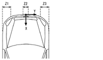
低出力エリアとなる部分としては、例えば、コーナー部が該当する。コーナー部では、図2に示すように、衝突の衝撃がコーナー部の形状に沿って分散する。すなわち、衝突の衝撃が車両の側方方向に逃されてしまうため、車両の背面方向に作用する力が小さくなる。その結果、歩行者等が前端部のコーナー部で衝突した場合には、車両の車幅方向中央付近で衝突した場合に比べて、出力値が小さくなりやすい。 For example, a corner portion corresponds to the low output area. In the corner portion, as shown in FIG. 2, the impact of the collision is distributed along the shape of the corner portion. That is, since the impact of the collision is released in the lateral direction of the vehicle, the force acting in the rear direction of the vehicle is reduced. As a result, when a pedestrian or the like collides at the corner portion of the front end, the output value tends to be smaller than when the vehicle collides near the center in the vehicle width direction.
なお、ここでの背面方向とは、車両の前端から後端に向かう方向を指し、側方方向とは、車幅方向に平行であって、かつ、車両の内側から外側に向かう方向を指す。図2の白塗り矢印は、車両に印加される衝撃の大きさを概念的に表しており、ハッチングを付与した矢印は、コーナー部に印加された衝撃のうち、背面方向に伝わる成分と、側方後方に伝わる成分を概念的に表している。 Here, the back direction refers to the direction from the front end to the rear end of the vehicle, and the side direction refers to the direction parallel to the vehicle width direction and from the inside to the outside of the vehicle. The white arrow in FIG. 2 conceptually represents the magnitude of the impact applied to the vehicle, and the hatched arrow represents the component transmitted in the rear direction and the side of the impact applied to the corner portion. The components transmitted to the rear are conceptually represented.
また、コーナー部以外の領域であっても、低出力エリアとなる場合もある。衝突センサ3の近くに、相対的に変形しにくい部材が配置されている場合には、当該部材が、衝突の衝撃による車体の変形や、衝突センサ3への衝撃の伝搬を阻害し、衝突センサ3の出力が出にくくなってしまう。そのような車体の変形を阻害するような相対的に硬い部材が、衝突検出センサ付近に配置されている部分も、低出力エリアとなりうる。
Further, even in a region other than the corner portion, there may be a low output area. When a member that is relatively difficult to deform is disposed near the
例えば、車幅方向の中央部では、ミリ波レーダ等の測距センサ5が、図3に示すように、衝突センサ3を構成する圧力チャンバ31の近くに位置するようにラジエータ6に固定されている場合がある。このように測距センサ5が圧力チャンバ31の近くに配置されている場合には、ラジエータ6によって支えられている測距センサ5が、圧力チャンバ31への衝撃の伝搬を阻害する要因(以降、阻害物)として作用する場合がある。
For example, at the center in the vehicle width direction, a
その結果、前端部の車幅方向中央付近であっても、低出力エリアとなる場合がある。特に、測距センサ5が、衝突センサ3を構成する圧力チャンバ31よりも車両前端側に配置されている場合には、測距センサ5が阻害物として作用しやすい。
As a result, there may be a low output area even in the vicinity of the center of the front end in the vehicle width direction. In particular, when the
もちろん、阻害物として作用する部材は、測距センサ5に限らない。前照灯やフォグランプなども、衝突センサ3に対する位置関係によっては、阻害物となりうる。つまり、車両前端部のうち、低出力エリアとなる部分は、車両前端部の形状や、車両前端部における部品の配置等といった、車両モデル毎の特性(以降、車両特性)によって定まる。
Of course, the member acting as an obstacle is not limited to the
本実施形態では一例として、図4に示すように前端部のうち、左側コーナー部Z1と、中央部Z2と、右側コーナー部Z3が低出力エリアとして設定されているものとする。 In the present embodiment, as an example, it is assumed that the left corner portion Z1, the central portion Z2, and the right corner portion Z3 of the front end portion are set as low output areas as shown in FIG.
なお、ここでの左側コーナー部Z1とは、車幅方向において最も左側となる部分から中央部側に一定距離(例えば0.4m)以内となるまでの領域とする。また、右側コーナー部Z3とは、車幅方向において最も右側となる部分から中央部側に一定距離(例えば0.4m)以内となるまでの領域とする。中央部Z2は、車幅方向の中央から左右に一定距離(例えば0.1m)以内となる領域とする。 Here, the left corner portion Z1 is a region from a portion on the left side in the vehicle width direction to a region within a certain distance (for example, 0.4 m) from the leftmost portion to the center portion. Further, the right corner portion Z3 is a region from a portion on the rightmost side in the vehicle width direction to a center distance that is within a certain distance (for example, 0.4 m). The central portion Z2 is a region that is within a certain distance (for example, 0.1 m) from the center in the vehicle width direction to the left and right.
なお、前端部における低出力エリアは、車両前後方向をX軸、車幅方向をY軸とする平面座標系(XY座標系とする)の座標によって表されればよい。XY座標系の原点は、例えば車両前端部のうち、車幅方向において中央となる点とすればよい。なお、X軸は、背面方向を正方向とし、Y軸は、車両左側から右側に向かう方向を正方向とする。 Note that the low output area at the front end may be represented by coordinates in a plane coordinate system (XY coordinate system) in which the vehicle longitudinal direction is the X axis and the vehicle width direction is the Y axis. The origin of the XY coordinate system may be, for example, the center point in the vehicle width direction in the front end portion of the vehicle. The X-axis has a back direction as the positive direction, and the Y-axis has a positive direction from the left side to the right side of the vehicle.
<ECU1の構成及び作動について>
次に、ECU1が備える機能について述べる。ECU1は、CPU11がROM13に格納されている制御プログラムを実行することで実現される機能ブロックとして、図5に示すように、衝突検知部F1、画像認識部F2、衝突対象情報取得部F3、及び、動作判定部F4を備える。また、衝突対象情報取得部F3は、より細かい機能ブロックとして、衝突対象特定部F31、及び、衝突位置取得部F32を備える。なお、ECU1が備える種々の機能ブロックのそれぞれは、一つあるいは複数のIC等によりハードウェア的に実現されてもよい。本実施形態では一例として、動作判定部F4の一部は、ハードウェア的に実現されているものとする。
<Configuration and operation of
Next, functions provided in the
衝突検知部F1は、衝突センサ3の出力値を取得し、その出力値を動作判定部F4に提供する。この衝突検知部F1が請求項に記載の出力値取得部に相当する。
The collision detection unit F1 acquires the output value of the
また、衝突検知部F1は、より好ましい態様として、衝突センサ3の出力値が、自車両以外の物体と自車両の前端部とが衝突(つまり1次衝突)したか否かを判定するための衝突判定閾値以上となっている場合に、1次衝突が発生したと判定する。そして、前端部における衝突が生じた旨を示す衝突検知信号を、衝突対象情報取得部F3に提供する。
Further, as a more preferable aspect, the collision detection unit F1 determines whether the output value of the
画像認識部F2は、カメラ2から入力される画像データを解析し、検出対象として予め設定されている物体の検出、及び、その種別の特定を実施する。例えば画像認識部F2は、画像データに対してエッジ検出などの公知の画像処理を行い、画像に含まれている全ての物体の輪郭を抽出する。そして、画像処理を施した画像データに対して、パターンマッチング処理を行うことによって、検出対象となっている物体を検出するとともに、その物体の種別を特定する。 The image recognition unit F2 analyzes the image data input from the camera 2, and detects an object preset as a detection target and specifies its type. For example, the image recognition unit F2 performs known image processing such as edge detection on the image data, and extracts the contours of all objects included in the image. Then, by performing pattern matching processing on the image data that has undergone image processing, an object that is a detection target is detected and the type of the object is specified.
検出対象とする物体は適宜設計されれば良い。本実施形態では、歩行者と、乗員が乗車している自転車(以降、乗員付き自転車)が、検出対象として登録されているものとする。乗員付き自転車を検出対象とすることは、自転車の乗員を検出対象とすることに相当する。なお、検出対象とする物体は、上述したものに限らない。原動機付き自転車や、自動二輪車、自動四輪車などといった、他の種別の移動体を検出対象として設定されていても良い。また、電柱などの構造物なども検出対象として設定されていても良い。 The object to be detected may be appropriately designed. In this embodiment, it is assumed that a pedestrian and a bicycle on which an occupant is riding (hereinafter, a bicycle with an occupant) are registered as detection targets. Setting a bicycle with an occupant as a detection target corresponds to setting a bicycle occupant as a detection target. The object to be detected is not limited to that described above. Other types of moving bodies such as a motorbike, a motorcycle, an automobile, and the like may be set as detection targets. A structure such as a utility pole may also be set as a detection target.
なお、画像認識部F2が画像データからこれらの検出対象とする物体を検出するために用いられるデータ(以降、画像認識用データ)は、ROM13に格納されていればよい。画像認識用データとは、例えば検出対象とする物体の形状パターンを表すデータなどが該当する。
Note that data (hereinafter, image recognition data) used for the image recognition unit F2 to detect these detection target objects from the image data may be stored in the
また、画像認識部F2は、画像データ内における検出した物体(以降、検出物)の位置や大きさから、検出物と自車両との相対位置を推定する。さらに、一旦検出した物体については、周知の物体追跡手法を援用して追尾する。これにより、複数の連続するフレーム間における同一検出物の位置や大きさの変化度合いから、当該検出物の相対的な移動方向や移動速度を推定する。なお、検出物の自車両に対する相対位置は、前述のXY座標系の座標によって表されればよい。 Further, the image recognition unit F2 estimates the relative position between the detected object and the host vehicle from the position and size of the detected object (hereinafter, detected object) in the image data. Furthermore, the object once detected is tracked with the aid of a well-known object tracking method. Thereby, the relative moving direction and moving speed of the detected object are estimated from the degree of change in the position and size of the same detected object between a plurality of consecutive frames. Note that the relative position of the detected object with respect to the host vehicle may be represented by the coordinates of the XY coordinate system described above.
なお、仮にカメラ2がステレオカメラである場合には、それぞれの画像データ内における同一物体の位置の差に基づいて相対位置を推定してもよい。画像認識部F2による画像認識処理の結果は、衝突対象情報取得部F3に提供される。画像認識部F2が請求項に記載の物体認識部に相当する。 If the camera 2 is a stereo camera, the relative position may be estimated based on the position difference of the same object in each image data. The result of the image recognition processing by the image recognition unit F2 is provided to the collision target information acquisition unit F3. The image recognition unit F2 corresponds to the object recognition unit described in the claims.
衝突対象情報取得部F3は、自車両前方に存在する物体についての情報として、画像認識部F2による画像認識処理の結果を取得する。具体的には、検出物毎の相対位置や相対速度、移動体としての種別などを取得する。 The collision target information acquisition unit F3 acquires the result of the image recognition process by the image recognition unit F2 as information about the object existing in front of the host vehicle. Specifically, the relative position and relative speed for each detected object, the type as a moving object, and the like are acquired.
そして、衝突対象情報取得部F3は、画像認識部F2による画像認識処理の結果に基づいて、自車両と衝突した物体(以降、衝突対象)を特定する。衝突対象情報取得部F3が備える衝突対象特定部F31、及び、衝突位置取得部F32は、衝突対象についての種々の情報を取得するための機能ブロックである。 Then, the collision target information acquisition unit F3 identifies an object (hereinafter referred to as a collision target) that has collided with the host vehicle based on the result of the image recognition processing by the image recognition unit F2. The collision target identification unit F31 and the collision position acquisition unit F32 included in the collision target information acquisition unit F3 are functional blocks for acquiring various information about the collision target.
衝突対象特定部F31は、衝突検知部F1が衝突の発生を検知した場合に、逐次収集している自車両前方に存在する物体についての情報に基づき、衝突対象を特定する。ここでは一例として、衝突対象特定部F31は、自車両前方に存在する検出物のうち、衝突発生時点において最も自車両に近い位置に存在している検出物が衝突対象であると判定する。なお、ここでの衝突発生時点とは、衝突する直前(例えば0.5秒前等)を含むものとする。 When the collision detection unit F1 detects the occurrence of a collision, the collision target specifying unit F31 specifies a collision target based on information about objects existing ahead of the host vehicle that are sequentially collected. Here, as an example, the collision target specifying unit F31 determines that, among the detection objects existing in front of the host vehicle, the detection object present at the position closest to the host vehicle at the time of the collision is the collision target. Here, the collision occurrence time point includes immediately before the collision (for example, 0.5 seconds before).
ただし、自車両から最も近い物体が、自車両から一定距離(例えば3m)以上離れている場合には、その検出物以外の物体と接触している可能性がある。したがって、最も自車両に近い位置に存在している検出物と自車両との距離が一定距離以上となっている場合には、衝突対象は、未検出の物体であると判定する。 However, when the object closest to the host vehicle is a certain distance (for example, 3 m) or more from the host vehicle, there is a possibility that the object is in contact with an object other than the detected object. Therefore, when the distance between the detected object present at the position closest to the host vehicle and the host vehicle is a certain distance or more, it is determined that the collision target is an undetected object.
なお、本実施形態では、衝突検知部F1が衝突の発生を検知したことをトリガとして、衝突対象を確定する態様とするが、これに限らない。画像認識部F2によって検出されている検出物のうち、相対速度などから定まる自車両と衝突するまでの残り時間としての衝突余裕時間が、一定時間(例えば0.5秒)未満となっている物体が存在する時点で、衝突対象を確定してもよい。つまり、衝突対象は、実際に1次衝突した物体だけでなく、これから1次衝突する物体であってもよい。 In the present embodiment, although the collision detection unit F1 detects the occurrence of the collision as a trigger, the collision target is determined, but the present invention is not limited to this. Among the detected objects detected by the image recognition unit F2, an object whose collision surplus time as a remaining time until it collides with the host vehicle determined from the relative speed is less than a certain time (for example, 0.5 seconds) The target of collision may be determined at the point in time when That is, the collision target may be not only an object that has actually undergone a primary collision, but also an object that will undergo a primary collision in the future.
衝突位置取得部F32は、画像認識部F2の認識結果に基づいて、自車両の前端部において衝突対象が衝突した位置(以降、衝突位置)を特定する。具体的には、衝突が検出された時点における衝突対象の相対位置を、衝突位置として取得する。衝突位置は、XY座標系の座標で表されればよい。なお、他の態様として衝突位置取得部F32は、衝突直前における衝突対象の相対位置をその時点における相対速度及び相対的な移動方向を用いて補正することで、衝突位置を推定してもよい。 The collision position acquisition unit F32 specifies the position (hereinafter referred to as the collision position) where the collision target collides at the front end portion of the host vehicle based on the recognition result of the image recognition unit F2. Specifically, the relative position of the collision target at the time when the collision is detected is acquired as the collision position. The collision position may be represented by coordinates in the XY coordinate system. As another aspect, the collision position acquisition unit F32 may estimate the collision position by correcting the relative position of the collision target immediately before the collision using the relative speed and the relative movement direction at that time.
また、衝突対象特定部F31によって衝突対象が乗員付き自転車であると判定されている場合には、衝突位置取得部F32は、その衝突対象としての乗員付き自転車の重心の位置を衝突位置として取得すればよい。 When the collision target specifying unit F31 determines that the collision target is a bicycle with an occupant, the collision position acquisition unit F32 acquires the position of the center of gravity of the bicycle with the occupant as the collision target as the collision position. That's fine.
乗員付き自転車における重心位置とは、自転車の前輪と後輪の中間となる位置とすればよい。他の態様として、運転者が乗車している位置(例えば運転者の腰の位置)を、乗員付き自転車における重心位置と見なしてもよい。また、サドルの位置を衝突位置と見なしてもよい。 The center-of-gravity position in the occupant-equipped bicycle may be a position that is intermediate between the front and rear wheels of the bicycle. As another aspect, the position on which the driver is riding (for example, the position of the driver's waist) may be regarded as the position of the center of gravity of the bicycle with the occupant. Further, the position of the saddle may be regarded as a collision position.
そして、衝突対象特定部F31によって特定されている衝突対象の移動体としての種別、及び、衝突位置取得部F32が取得した衝突位置は、動作判定部F4に提供される。 Then, the type of the collision target identified by the collision target identification unit F31 and the collision position acquired by the collision position acquisition unit F32 are provided to the operation determination unit F4.
動作判定部F4は、衝突検知部F1から提供される出力値Pに基づいて、外部保護装置4を動作させるべきか否かを判定する。そして、外部保護装置4を動作させるべきであると判定した場合には、外部保護装置4に対して、動作するように指示する動作指示信号を出力し、動作させる。 The operation determination unit F4 determines whether or not the external protection device 4 should be operated based on the output value P provided from the collision detection unit F1. When it is determined that the external protection device 4 should be operated, an operation instruction signal for instructing the external protection device 4 to operate is output and operated.
ここでは一例として、デフォルト閾値と、歩行者用閾値と、自転車用閾値の3種類の閾値が用意されており、動作判定部F4は、衝突位置や衝突対象の移動体としての種別に応じて、それら3つの閾値うちの何れかを動作閾値として採用する。そして、出力値Pが動作閾値として採用している閾値を超過している場合に、外部保護装置4を動作させるべきであると判定する。 Here, as an example, three types of threshold values, a default threshold value, a pedestrian threshold value, and a bicycle threshold value, are prepared, and the motion determination unit F4 is configured according to the collision position and the type of the moving object as a collision target. Any one of these three threshold values is adopted as the operation threshold value. Then, when the output value P exceeds the threshold adopted as the operation threshold, it is determined that the external protection device 4 should be operated.
デフォルト閾値ThDは、衝突位置が低出力エリア以外である場合に用いる閾値である。デフォルト閾値ThDは、適宜設計されれば良い。ただし、デフォルト閾値ThDは、少なくとも前述の衝突検知閾値よりは大きく、更には、小動物(例えば猫)やロードコーン等といった、人間よりも十分に質量が軽い物体との衝突では超過しない値となっていることが好ましい。デフォルト閾値ThDは、ダミー人形等を用いた実試験やシミュレーション等(以降、実試験等)によって決定されれば良い。 The default threshold ThD is a threshold used when the collision position is outside the low output area. The default threshold ThD may be designed as appropriate. However, the default threshold ThD is at least larger than the above-described collision detection threshold, and further does not exceed a collision with an object that is sufficiently lighter than a human, such as a small animal (for example, a cat) or a road cone. Preferably it is. The default threshold ThD may be determined by an actual test, a simulation, or the like (hereinafter, an actual test) using a dummy doll or the like.
歩行者用閾値ThWは、低出力エリアに歩行者が衝突した場合を想定した閾値である。例えば歩行者用閾値ThWは、低出力エリアに歩行者が衝突した場合に衝突センサ3が出力しうる出力値Pの最小値とすればよい。低出力エリアに歩行者が衝突した場合に衝突センサ3が出力しうる出力値Pの最小値は、実試験等によって決定されればよい。歩行者用閾値ThWは、デフォルト閾値ThDよりも小さく設定される。
The pedestrian threshold ThW is a threshold that assumes a case where a pedestrian collides with a low output area. For example, the pedestrian threshold ThW may be the minimum value of the output value P that can be output by the
自転車用閾値ThBは、低出力エリアに乗員付き自転車が衝突した場合を想定した閾値である。自転車用閾値ThBは、例えば、低出力エリアに乗員付き自転車が衝突した場合に衝突センサ3が出力しうる出力値Pの最小値とすればよい。低出力エリアに乗員付き自転車が衝突した場合に衝突センサ3が出力しうる出力値Pの最小値もまた、実試験等によって決定されればよい。自転車用閾値ThBは、歩行者用閾値ThWよりも小さく設定される。
The bicycle threshold ThB is a threshold that is assumed when a bicycle with a passenger collides with a low output area. For example, the bicycle threshold ThB may be a minimum value of the output value P that can be output by the
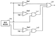
この動作判定部F4が、衝突位置、及び、衝突対象の移動体としての種別に応じた動作閾値を用いて外部保護装置4の動作の是非を判定するための構成の一例を図6に示す。動作判定部F4は、図6に示すように条件判定部F41、比較器Cmp1〜3、AND素子Lc1〜2、及びOR素子Ld1を備える。 FIG. 6 shows an example of a configuration for the operation determination unit F4 to determine whether the external protection device 4 operates properly by using an operation threshold corresponding to the collision position and the type of the collision target moving body. As illustrated in FIG. 6, the operation determination unit F4 includes a condition determination unit F41, comparators Cmp1 to Cmp1 to 3, AND elements Lc1 to Lc2, and an OR element Ld1.
比較器Cmp1〜3のそれぞれは、プラス側入力端子とマイナス側入力端子を備え、プラス側入力端子に入力されている値(例えば電圧値)が、マイナス側入力端子よりも大きい場合にハイレベルの信号(換言すれば正論理回路での1)を出力する素子又は回路である。比較器Cmp1〜3のそれぞれのプラス側入力端子には、衝突センサ3の出力値Pが入力されている。
Each of the comparators Cmp1 to Cmp3 includes a plus-side input terminal and a minus-side input terminal. When the value (for example, voltage value) input to the plus-side input terminal is larger than the minus-side input terminal, the comparators Cmp1 to Cmp3 are high level. An element or circuit that outputs a signal (in other words, 1 in a positive logic circuit). The output value P of the
比較器Cmp1のマイナス側入力端子には、デフォルト閾値ThDに対応する電圧が入力されている。つまり、比較器Cmp1は、衝突センサ3の出力値Pとデフォルト閾値ThDを比較し、衝突センサ3の出力値Pがデフォルト閾値ThDを超過している場合に、ハイレベルを出力するように構成されている。比較器Cmp1の出力は、OR素子Ld1に入力される。
A voltage corresponding to the default threshold ThD is input to the negative side input terminal of the comparator Cmp1. That is, the comparator Cmp1 is configured to compare the output value P of the
比較器Cmp2のマイナス側入力端子には、歩行者用閾値ThWに対応する電圧が入力されている。また、比較器Cmp2の出力は、AND素子Lc1に入力される。つまり、比較器Cmp2は、衝突センサ3の出力値Pと歩行者用閾値ThWを比較し、衝突センサ3の出力値Pが歩行者用閾値ThWを超過している場合に、ハイレベルを出力するように構成されている。
A voltage corresponding to the pedestrian threshold ThW is input to the negative input terminal of the comparator Cmp2. The output of the comparator Cmp2 is input to the AND element Lc1. That is, the comparator Cmp2 compares the output value P of the
比較器Cmp3のマイナス側入力端子には、自転車用閾値ThBに対応する電圧が入力されている。また、比較器Cmp3の出力は、AND素子Lc2に入力される。つまり、比較器Cmp3は、衝突センサ3の出力値Pと自転車用閾値ThBを比較し、衝突センサ3の出力値Pが自転車用閾値ThBを超過している場合に、AND素子Lc2にハイレベルを入力するように構成されている。
A voltage corresponding to the bicycle threshold ThB is input to the negative side input terminal of the comparator Cmp3. The output of the comparator Cmp3 is input to the AND element Lc2. That is, the comparator Cmp3 compares the output value P of the
条件判定部F41は、歩行者用閾値ThWを動作閾値として採用するための条件を充足しているか否か、及び、自転車用閾値ThBを動作閾値として採用するための条件を充足しているか否かを判定する。なお、歩行者用閾値ThWを動作閾値として採用するための条件とは、換言すれば、歩行者用閾値ThWを用いた判定結果を有効化するための条件に相当する。また、自転車用閾値ThBを動作閾値として採用するための条件とは、自転車用閾値ThBを用いた判定結果を有効化するための条件に相当する。 Whether the condition determination unit F41 satisfies the condition for adopting the pedestrian threshold ThW as the motion threshold and whether the condition for employing the bicycle threshold ThB as the motion threshold is satisfied Determine. In addition, the condition for adopting the pedestrian threshold ThW as the operation threshold corresponds to a condition for validating the determination result using the pedestrian threshold ThW. The condition for adopting the bicycle threshold ThB as the operation threshold corresponds to a condition for validating the determination result using the bicycle threshold ThB.
この条件判定部F41は、具体的にはまず、衝突位置取得部F32によって取得されている衝突位置が低出力エリアとなっているか否かを判定する。そして、衝突位置が低出力エリアとなっている場合には、衝突対象特定部F31によって取得されている衝突対象は、歩行者であるか否かを判定する。また、衝突対象が、歩行者ではない場合には、衝突対象が乗員付き自転車であるか否かを判定する。 Specifically, the condition determination unit F41 first determines whether or not the collision position acquired by the collision position acquisition unit F32 is a low output area. When the collision position is a low output area, it is determined whether or not the collision target acquired by the collision target specifying unit F31 is a pedestrian. Further, when the collision target is not a pedestrian, it is determined whether or not the collision target is a bicycle with an occupant.
衝突位置が低出力エリアであって、かつ、衝突対象が歩行者である場合には、歩行者用閾値ThWを動作閾値として採用するための条件を充足していると判定し、AND素子Lc1にハイレベルを入力する。なお、歩行者用閾値ThWを動作閾値として採用するための条件が充足されていない場合には、ローレベル(換言すれば正論理回路での0)をAND素子Lc1に入力する。 When the collision position is a low output area and the collision target is a pedestrian, it is determined that the condition for adopting the pedestrian threshold ThW as the operation threshold is satisfied, and the AND element Lc1 Enter a high level. Note that when the condition for adopting the pedestrian threshold ThW as the operation threshold is not satisfied, a low level (in other words, 0 in the positive logic circuit) is input to the AND element Lc1.
また、衝突位置が低出力エリアであって、かつ、衝突対象が乗員付き自転車である場合には、自転車用閾値ThBを動作閾値として採用するための条件を充足していると判定し、AND素子Lc2にハイレベルを入力する。なお、自転車用閾値ThBを動作閾値として採用するための条件が充足されていない場合には、ローレベルをAND素子Lc2に入力する。 Further, when the collision position is a low output area and the collision target is a bicycle with an occupant, it is determined that the condition for adopting the bicycle threshold ThB as the operation threshold is satisfied, and the AND element A high level is input to Lc2. Note that if the condition for adopting the bicycle threshold ThB as the operation threshold is not satisfied, a low level is input to the AND element Lc2.
AND素子Lc1は、比較器Cmp2及び条件判定部F41の両方からハイレベルが入力されている場合にのみ、ハイレベルをOR素子Ld1に出力する。つまり、衝突位置が低出力エリアであり、かつ、衝突対象が歩行者であり、かつ、出力値Pが歩行者用閾値ThWを超過している場合に、AND素子Lc1からOR素子Ld1にハイレベルが入力される。 The AND element Lc1 outputs a high level to the OR element Ld1 only when a high level is input from both the comparator Cmp2 and the condition determination unit F41. That is, when the collision position is a low output area, the collision target is a pedestrian, and the output value P exceeds the pedestrian threshold ThW, the AND element Lc1 is switched to the OR element Ld1. Is entered.
AND素子Lc2は、比較器Cmp3及び条件判定部F41の両方からハイレベルが入力されている場合にのみ、ハイレベルをOR素子Ld1に出力する。つまり、衝突位置が低出力エリアであり、かつ、衝突対象が乗員付き自転車であり、かつ、出力値Pが自転車用閾値ThBを超過している場合に、AND素子Lc2からOR素子Ld1にハイレベルが入力される。 The AND element Lc2 outputs a high level to the OR element Ld1 only when a high level is input from both the comparator Cmp3 and the condition determination unit F41. That is, when the collision position is a low output area, the collision target is a bicycle with an occupant, and the output value P exceeds the bicycle threshold ThB, a high level is output from the AND element Lc2 to the OR element Ld1. Is entered.
OR素子Ld1は、複数の入力に対する論理和を出力する論理素子である。OR素子Ld1は、比較器Cmp1、AND素子Lc1、AND素子Lc2の少なくとも何れか1つからハイレベルが入力されている場合に、ハイレベルを出力する。動作判定部F4は、OR素子Ld1の出力がハイレベルとなった場合に、外部保護装置4に対して、動作するように指示する動作指示信号を出力する。なお、OR素子Ld1の出力信号を、そのまま動作指示信号として用いても良い。つまり、外部保護装置4を、OR素子Ld1の出力がハイレベルとなった場合に動作するように構成してもよい。 The OR element Ld1 is a logic element that outputs a logical sum for a plurality of inputs. The OR element Ld1 outputs a high level when a high level is input from at least one of the comparator Cmp1, the AND element Lc1, and the AND element Lc2. The operation determination unit F4 outputs an operation instruction signal instructing the external protection device 4 to operate when the output of the OR element Ld1 becomes a high level. Note that the output signal of the OR element Ld1 may be used as it is as an operation instruction signal. That is, the external protection device 4 may be configured to operate when the output of the OR element Ld1 becomes high level.
以上の構成によれば、動作判定部F4全体としては、動作閾値として、デフォルト閾値ThDと、歩行者用閾値ThWと、自転車用閾値ThBの3種類の閾値の何れかを動作閾値として採用し、その動作閾値を出力値Pが超過している場合に、外部保護装置4を動作させることになる。 According to the above configuration, the motion determination unit F4 as a whole employs, as the motion threshold, any one of the three thresholds of the default threshold ThD, the pedestrian threshold ThW, and the bicycle threshold ThB as the motion threshold. When the output value P exceeds the operation threshold, the external protection device 4 is operated.
歩行者用閾値ThW及び自転車用閾値ThBはともに、衝突位置が低出力エリアとなっている場合に動作閾値として採用される閾値であり、デフォルト閾値ThDよりも小さい値に設定されている。つまり、歩行者用閾値ThW及び自転車用閾値ThBのそれぞれが請求項に記載の低出力エリア用閾値に相当する。 Both the pedestrian threshold ThW and the bicycle threshold ThB are thresholds that are employed as operation thresholds when the collision position is in a low output area, and are set to values smaller than the default threshold ThD. In other words, each of the pedestrian threshold ThW and the bicycle threshold ThB corresponds to the low output area threshold described in the claims.
<実施形態のまとめ>
以上の構成では、衝突位置が低出力エリアとなっていない場合には、衝突センサの出力値Pがデフォルト閾値ThDを超過している場合に、外部保護装置4を動作させる。つまり、デフォルト閾値ThDを動作閾値として採用して、外部保護装置4を動作させるか否かを判定することになる。
<Summary of Embodiment>
In the above configuration, when the collision position is not in the low output area, the external protection device 4 is operated when the output value P of the collision sensor exceeds the default threshold ThD. That is, it is determined whether or not to operate the external protection device 4 by adopting the default threshold ThD as the operation threshold.
一方、衝突位置が低出力エリアとなっており、かつ、衝突対象が歩行者である場合には、衝突センサの出力値Pが歩行者用閾値ThWを超過した場合に、外部保護装置4を動作させる。つまり、衝突位置が低出力エリアとなっており、かつ、衝突対象が歩行者である場合には、歩行者用閾値ThWを動作閾値として採用して、外部保護装置4を動作させるか否かを判定することになる。 On the other hand, when the collision position is a low output area and the collision target is a pedestrian, the external protection device 4 is operated when the output value P of the collision sensor exceeds the pedestrian threshold ThW. Let That is, when the collision position is a low output area and the collision target is a pedestrian, whether or not to operate the external protection device 4 by adopting the pedestrian threshold ThW as an operation threshold. It will be judged.
この歩行者用閾値ThWは、デフォルト閾値ThDよりも小さい値であって、低出力エリアに歩行者が衝突した場合を想定した閾値である。したがって、以上の構成によれば、歩行者が低出力エリアに衝突した場合に、外部保護装置4が動作しない恐れは低減される。すなわち、前端部での衝突位置に起因して外部保護装置4が動作しない恐れを低減できる。 This pedestrian threshold ThW is a value that is smaller than the default threshold ThD, and is a threshold that assumes a case where a pedestrian collides with a low output area. Therefore, according to the above configuration, when the pedestrian collides with the low output area, the possibility that the external protection device 4 does not operate is reduced. That is, the possibility that the external protection device 4 does not operate due to the collision position at the front end can be reduced.
また、衝突位置が低出力エリアとなっており、かつ、衝突対象が乗員付き自転車である場合には、衝突センサの出力値Pが自転車用閾値ThBを超過した場合に、外部保護装置4を動作させる。つまり、衝突位置が低出力エリアとなっており、かつ、衝突対象が乗員付き自転車である場合には、自転車用閾値ThBを動作閾値として採用して、外部保護装置4を動作させるか否かを判定することになる。 When the collision position is a low output area and the collision target is a bicycle with an occupant, the external protection device 4 operates when the output value P of the collision sensor exceeds the bicycle threshold ThB. Let That is, when the collision position is a low output area and the collision target is a bicycle with an occupant, whether or not to operate the external protection device 4 by adopting the bicycle threshold ThB as the operation threshold. It will be judged.
この自転車用閾値ThBも、デフォルト閾値ThDよりも小さい値であって、低出力エリアに乗員付き自転車が衝突した場合を想定した値となっている。このような構成によれば、乗員付き自転車が低出力エリアに衝突した場合に、外部保護装置4が動作しない恐れを低減できる。つまり、前端部での衝突位置に起因して外部保護装置4が動作しない恐れを低減できる。 This bicycle threshold value ThB is also a value that is smaller than the default threshold value ThD, and is a value that assumes a case where a bicycle with a passenger collides with the low output area. According to such a configuration, it is possible to reduce the possibility that the external protection device 4 does not operate when a bicycle with a passenger collides with a low output area. That is, the possibility that the external protection device 4 does not operate due to the collision position at the front end can be reduced.
さらに、本実施形態では、自転車用閾値ThBを、歩行者用閾値ThWよりも小さい値に設定している。衝突対象が乗員付き自転車の場合には、衝突対象が歩行者の場合よりも衝突センサ3の出力値Pが抑制される傾向がある。したがって、本実施形態のように、自転車用閾値ThBを歩行者用閾値ThWよりも小さい値に設定することで、衝突対象が乗員付き自転車である場合に外部保護装置4が動作しない可能性を抑制できる。
Furthermore, in the present embodiment, the bicycle threshold ThB is set to a value smaller than the pedestrian threshold ThW. When the collision target is a bicycle with an occupant, the output value P of the
ところで、衝突位置が低出力エリアであることに起因する外部保護装置4の不動作を抑制するための他の構成としては、衝突位置が低出力エリアであっても外部保護装置4が動作するように、デフォルト閾値を十分に小さい値に設定しておく構成も考えられる。便宜上、そのような構成を比較構成と称する。 By the way, as another configuration for suppressing the non-operation of the external protection device 4 due to the collision position being in the low output area, the external protection device 4 operates even when the collision position is in the low output area. In addition, a configuration in which the default threshold is set to a sufficiently small value is also conceivable. For convenience, such a configuration is referred to as a comparative configuration.
しかしながら、そのような比較構成においては、小動物やロードコーンといった外部保護装置4を動作させる必要がない物体との衝突によって、外部保護装置を動作させてしまう恐れが高まる。つまり、比較構成では、外乱などで外部保護装置を不必要に動作させてしまう恐れが高まってしまう。 However, in such a comparative configuration, there is an increased risk of operating the external protection device due to a collision with an object that does not require operation of the external protection device 4 such as a small animal or a load cone. That is, in the comparison configuration, there is an increased risk that the external protection device will be operated unnecessarily due to disturbance or the like.
そのような課題に対し、本実施形態の構成によれば、外部保護装置4の誤動作を抑制しつつ、前端部での衝突位置に起因して外部保護装置4が動作しない恐れを低減することができる。つまり、より適切に外部保護装置4を動作させることが出来る。 In response to such a problem, according to the configuration of the present embodiment, it is possible to reduce the possibility that the external protection device 4 will not operate due to the collision position at the front end while suppressing the malfunction of the external protection device 4. it can. That is, the external protection device 4 can be operated more appropriately.
以上、本発明の実施形態を説明したが、本発明は上述の実施形態に限定されるものではなく、以降で述べる種々の変形例も本発明の技術的範囲に含まれ、さらに、下記以外にも要旨を逸脱しない範囲内で種々変更して実施することができる。 As mentioned above, although embodiment of this invention was described, this invention is not limited to the above-mentioned embodiment, The various modifications described below are also contained in the technical scope of this invention, and also in addition to the following However, various modifications can be made without departing from the scope of the invention.
[変形例1]
衝突対象特定部F31は、衝突対象が乗員付き自転車であると判定している場合には、さらに、画像認識部F2と協働し、自車両に対する当該乗員付き自転車の姿勢に応じた閾値を動作閾値として採用する態様としてもよい(これを変形例1とする)。
[Modification 1]
When the collision target specifying unit F31 determines that the collision target is a bicycle with an occupant, the collision target specifying unit F31 further operates in conjunction with the image recognition unit F2 to operate a threshold value according to the posture of the bicycle with the occupant with respect to the host vehicle. It is good also as an aspect employ | adopted as a threshold value (this is set as the modification 1).
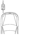
この変形例1は、例えば次のように実現されればよい。まず、画像認識部F2は、乗員付き自転車を検出している場合に、その自転車の自車両に対する姿勢が、横向き姿勢となっているか、縦向き姿勢となっているかを判定する。ここでの横向き姿勢とは、図7に示すように、自車両の進行方向に対する乗員付き自転車の進行方向が垂直となる姿勢である。また、縦向き姿勢とは、図8に示すように、自車両の進行方向に対する乗員付き自転車の進行方向が平行となる姿勢である。 For example, the first modification may be realized as follows. First, when detecting a bicycle with an occupant, the image recognition unit F2 determines whether the posture of the bicycle with respect to the host vehicle is a landscape orientation or a portrait orientation. Here, as shown in FIG. 7, the lateral orientation is an orientation in which the traveling direction of the bicycle with the occupant is perpendicular to the traveling direction of the host vehicle. Further, as shown in FIG. 8, the vertical posture is a posture in which the traveling direction of the bicycle with the occupant is parallel to the traveling direction of the host vehicle.
なお、ここでの垂直とは、完全な垂直に限らず、略垂直を含む。同様に、平行とは、完全な平行に限らず、略平行を含む。例えば、自車両の進行方向に対する乗員付き自転車の進行方向が為す角度の絶対値が45度〜135度以内である場合には横向き姿勢であると見なし、他の場合は縦向き姿勢であると見なせば良い。検出物としての乗員付き自転車が縦向き姿勢となっているか横向き姿勢となっているかを示す情報は、当該検出物の相対位置や、移動体としての種別を示す情報と対応付けて衝突対象情報取得部F3に提供する。 Note that the vertical here is not limited to complete vertical, but includes substantially vertical. Similarly, the term “parallel” includes not only complete parallel but also substantially parallel. For example, when the absolute value of the angle formed by the traveling direction of the cyclist with the occupant relative to the traveling direction of the host vehicle is within 45 degrees to 135 degrees, it is regarded as a horizontal posture, and in other cases, it is regarded as a vertical posture. What should I do? Information indicating whether a bicycle with a passenger as a detected object is in a portrait orientation or a landscape orientation is obtained by associating with the relative position of the detected object or information indicating the type as a moving object. Provided to part F3.
衝突対象特定部F31は、衝突対象が乗員付き自転車であると判定している場合には、さらに、画像認識部F2から提供される情報に基づき、衝突対象としての乗員付き自転車の自車両に対する姿勢が、横向き姿勢となっているか縦向き姿勢となっているかを認識する。 When the collision target specifying unit F31 determines that the collision target is a bicycle with an occupant, the position of the cyclist with an occupant as a collision target with respect to the host vehicle is further based on information provided from the image recognition unit F2. Recognizes whether it is in a landscape orientation or a portrait orientation.
そして、動作判定部F4は、衝突対象としての乗員付き自転車が、縦向き姿勢となっている場合には、横向き姿勢となっている場合よりも小さい閾値を動作閾値として採用して、外部保護装置4を動作させるべきか否かを判定する。例えば、自転車用閾値として、乗員付き自転車が横向き姿勢で自車両と衝突する場合を想定した横向き用閾値と、その横向き用閾値よりも小さい、乗員付き自転車が縦向き姿勢で自車両と衝突する場合を想定した縦向き用閾値とを予め設定しておけばよい。 Then, the motion determination unit F4 adopts a smaller threshold as the motion threshold when the passenger-equipped bicycle as the collision target is in the vertical posture than in the horizontal posture, and the external protection device 4 is determined whether or not to operate. For example, as a threshold for a bicycle, when a bicycle with an occupant collides with the own vehicle in a sideways posture, and when the bicycle with an occupant collides with the own vehicle in a vertical posture that is smaller than the threshold for the sideways It is only necessary to set in advance a vertical direction threshold value assuming the above.
縦向き用閾値を横向き用閾値よりも小さい値とする理由は次の通りである。自転車が縦向き姿勢で衝突した場合、自転車において自車両前端部と直接的に衝突する部分は、自転車の車輪となる。自転車が縦向き姿勢で衝突した場合は、横向き姿勢で衝突した場合に比べて、自車両の前端部と接触する面積が小さいため、衝突の衝撃が衝突センサ3に伝わりにくい。特に低出力エリアでは、衝撃が自車両側方に逃されたり、衝撃が阻害物によって自転車に作用したりしやすい。
The reason why the vertical threshold is set smaller than the horizontal threshold is as follows. When the bicycle collides in a vertical orientation, the portion of the bicycle that directly collides with the front end of the host vehicle becomes the wheel of the bicycle. When the bicycle collides in a vertical posture, the impact of the collision is less likely to be transmitted to the
また、自転車の車輪は相対的に変形しやすく、且つ、自転車自体が路面との摩擦が小さい。そのため、衝突の衝撃によって自車両の進行方向に滑りやすい。その結果、横向き姿勢で衝突した場合に比べて、衝突の衝撃が自車両側に伝わりにくく、衝突センサ3の出力が小さくなりやすい。
In addition, the bicycle wheel is relatively easily deformed, and the bicycle itself has little friction with the road surface. Therefore, it is easy to slip in the traveling direction of the host vehicle due to the impact of the collision. As a result, the impact of the collision is less likely to be transmitted to the own vehicle side and the output of the
したがって、衝突対象としての乗員付き自転車が縦向き姿勢となっている場合には、横向き姿勢となっている場合に比べて相対的に小さい値を動作閾値として採用することで、より適切に外部保護装置を動作するべきか否かを判定できるようになる。 Therefore, when the bicycle with occupant as the collision target is in the vertical orientation, the external protection is more appropriately applied by adopting a relatively small value as the operation threshold compared to the case of the horizontal orientation. It becomes possible to determine whether or not to operate the device.
なお、自転車の衝突時の姿勢に由来する上述した傾向は、前端部の低出力エリア以外の部分でも同様である。つまり、低出力エリア以外の部分でも、衝突対象としての乗員付き自転車が、縦向き姿勢で衝突した場合には、横向き姿勢で衝突した場合に比べて、衝突センサ3の出力が出にくい。
In addition, the tendency mentioned above derived from the posture at the time of the collision of the bicycle is the same in portions other than the low output area at the front end. That is, even in a portion other than the low output area, when the bicycle with a passenger as a collision target collides in a vertical posture, the output of the
したがって、衝突位置が低出力エリア以外となっている場合にも、衝突対象が乗員付き自転車である場合には自車両と衝突した自転車の姿勢に応じた閾値を適用することが好ましい。つまり、衝突位置に関わらず、衝突対象が乗員付き自転車であって、その衝突時の姿勢が縦向き姿勢である場合には、横向き姿勢である場合よりも小さい閾値を動作閾値として採用して、外部保護装置4を動作させるか否かを判定することが好ましい。 Therefore, even when the collision position is outside the low output area, it is preferable to apply a threshold value corresponding to the posture of the bicycle that collided with the host vehicle when the collision target is a bicycle with an occupant. In other words, regardless of the collision position, when the collision target is a bicycle with a passenger and the posture at the time of the collision is a vertical posture, a threshold smaller than the case of the horizontal posture is adopted as the operation threshold, It is preferable to determine whether or not to operate the external protection device 4.
つまり、デフォルト閾値として、縦向き用閾値や、横向き用閾値などに相当する複数種類の閾値が設定されていることが好ましい。 That is, it is preferable that a plurality of types of threshold values corresponding to a vertical threshold value, a horizontal threshold value, and the like are set as default threshold values.
[変形例2]
上述の実施形態では、衝突位置が低出力エリアである場合に、さらに、歩行者や自転車といった衝突対象の移動体としての種別を考慮して動作閾値を決定する態様を例示したが、これに限らない。例えば、衝突位置が低出力エリアか否かだけに基づいて、動作閾値を選択する態様としてもよい(これを変形例2とする)。
[Modification 2]
In the above-described embodiment, when the collision position is a low output area, the mode in which the operation threshold is determined in consideration of the type as the collision target moving body such as a pedestrian or a bicycle is exemplified. Absent. For example, it is good also as an aspect which selects an operation | movement threshold value only based on whether a collision position is a low output area (this is set as the modification 2).
便宜上、衝突位置が低出力エリアとなっている場合に動作閾値として用いる閾値を、低出力エリア用閾値と称する。低出力エリア用閾値は、デフォルト閾値ThDよりも小さければよい。ただし、低出力用エリアに小動物やロードコーン等が衝突した場合に観測されうる出力値Pよりも大きい値となっていることが好ましい。低出力エリア用閾値は、実試験等によって決定されればよい。 For convenience, a threshold used as an operation threshold when the collision position is a low output area is referred to as a low output area threshold. The low output area threshold may be smaller than the default threshold ThD. However, it is preferable that the value be larger than the output value P that can be observed when a small animal, a road cone, or the like collides with the low output area. The threshold for the low output area may be determined by an actual test or the like.
この変形例2における動作判定部F4は、衝突位置に応じた動作閾値を用いて外部保護装置4を動作させるべきか否かを判定するための構成として、図9に示すように衝突位置判定部G41、比較器Cmp4〜5、AND素子Lc3、及びOR素子Ld2を備える。 As shown in FIG. 9, the motion determination unit F4 according to the second modification has a configuration for determining whether or not the external protection device 4 should be operated using an operation threshold value corresponding to the collision position. G41, comparators Cmp4 to Cmp5, an AND element Lc3, and an OR element Ld2.
比較器Cmp4〜5のそれぞれは、前述の比較器Cmp1〜3に相当する部材である。比較器Cmp4〜5のそれぞれのプラス側入力端子には、衝突センサ3の出力値Pが入力されている。
Each of the comparators Cmp4 to Cmp5 is a member corresponding to the above-described comparators Cmp1 to Cmp3. The output value P of the
比較器Cmp4のマイナス側入力端子には、デフォルト閾値ThDに対応する電圧が入力されている。比較器Cmp4の出力は、OR素子Ld2に入力される。つまり、比較器Cmp4は、衝突センサ3の出力値Pとデフォルト閾値ThDを比較し、衝突センサ3の出力値Pがデフォルト閾値ThDを超過している場合に、ハイレベルを出力するように構成されている。
A voltage corresponding to the default threshold ThD is input to the negative side input terminal of the comparator Cmp4. The output of the comparator Cmp4 is input to the OR element Ld2. That is, the comparator Cmp4 is configured to compare the output value P of the
比較器Cmp5のマイナス側入力端子には、所定の低出力エリア用閾値Thαに対応する電圧が入力されている。また、比較器Cmp5の出力は、AND素子Lc3に入力される。つまり、比較器Cmp5は、衝突センサ3の出力値Pと低出力エリア用閾値Thαを比較し、衝突センサ3の出力値Pが低出力エリア用閾値Thαを超過している場合にAND素子Lc3にハイレベルを出力するように構成されている。
A voltage corresponding to a predetermined low output area threshold Thα is input to the negative input terminal of the comparator Cmp5. The output of the comparator Cmp5 is input to the AND element Lc3. That is, the comparator Cmp5 compares the output value P of the
衝突位置判定部G41は、衝突位置取得部F32によって取得されている衝突位置が低出力エリアとなっているか否かを判定する。そして、衝突位置が低出力エリアとなっている場合には、AND素子Lc3にハイレベルを入力する。また、衝突位置が低出力エリアとなっていない場合には、ローレベルをAND素子Lc2に入力する。 The collision position determination unit G41 determines whether or not the collision position acquired by the collision position acquisition unit F32 is a low output area. When the collision position is a low output area, a high level is input to the AND element Lc3. When the collision position is not in the low output area, the low level is input to the AND element Lc2.
AND素子Lc3は、比較器Cmp5及び衝突位置判定部G41の両方からハイレベルが入力されている場合にのみ、ハイレベルをOR素子Ld2に出力する。つまり、衝突位置が低出力エリアであり、かつ、出力値Pが低出力エリア用閾値Thαを超過している場合に、AND素子Lc3からOR素子Ld2にハイレベルが入力される。 The AND element Lc3 outputs a high level to the OR element Ld2 only when a high level is input from both the comparator Cmp5 and the collision position determination unit G41. That is, when the collision position is the low output area and the output value P exceeds the low output area threshold Thα, a high level is input from the AND element Lc3 to the OR element Ld2.
OR素子Ld1は、比較器Cmp4及びAND素子Lc2の少なくとも何れか一方からハイレベルが入力されている場合に、ハイレベルを出力する。 The OR element Ld1 outputs a high level when a high level is input from at least one of the comparator Cmp4 and the AND element Lc2.
動作判定部F4は、OR素子Ld2の出力がハイレベルとなった場合に、外部保護装置4に対して、動作するように指示する動作指示信号を出力する。なお、OR素子Ld2の出力信号を、そのまま動作指示信号として用いても良い。つまり、外部保護装置4を、OR素子Ld2の出力がハイレベルとなった場合に動作するように構成してもよい。 The operation determination unit F4 outputs an operation instruction signal instructing the external protection device 4 to operate when the output of the OR element Ld2 becomes high level. Note that the output signal of the OR element Ld2 may be used as it is as an operation instruction signal. That is, the external protection device 4 may be configured to operate when the output of the OR element Ld2 becomes high level.
以上の構成によれば、動作判定部F4全体としては、衝突位置が低出力エリア以外の部分である場合には動作閾値としてデフォルト閾値ThDを採用する一方、衝突位置が低出力エリアとなっている場合には、低出力エリア用閾値Thαを動作閾値として採用することになる。そして、その採用した動作閾値を出力値Pが超過している場合に、外部保護装置4は動作する。 According to the above configuration, the motion determination unit F4 as a whole adopts the default threshold ThD as the operation threshold when the collision position is a part other than the low output area, while the collision position is the low output area. In this case, the low output area threshold Thα is adopted as the operation threshold. When the output value P exceeds the adopted operation threshold, the external protection device 4 operates.
[変形例3]
上述の変形例2では、低出力エリア用閾値を固定値とする態様を例示したが、これに限らない。動作判定部F4は画像認識部F2から衝突対象の大きさを示す情報を取得し、低出力エリア用閾値を、衝突対象の大きさに応じた値に動的に調整する態様としてもよい(これを変形例3とする)。衝突対象が大きいほど、衝突の衝撃は大きくなることが期待されるためである。
[Modification 3]
In the above-described modification 2, the mode in which the low output area threshold value is set to the fixed value is illustrated, but the present invention is not limited to this. The motion determination unit F4 may acquire information indicating the size of the collision target from the image recognition unit F2, and dynamically adjust the threshold for the low output area to a value corresponding to the size of the collision target (this) As modified example 3). This is because the impact of the collision is expected to increase as the collision target increases.
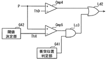
以下、この変形例3における動作判定部F4の概略的な構成及び作動を図10、図11を用いて説明する。変形例3における動作判定部F4は、図10に示すように、衝突位置判定部G41、閾値決定部G42、比較器Cmp4〜5、AND素子Lc3、及びOR素子Ld2を備える。
Hereinafter, a schematic configuration and operation of the operation determination unit F4 in
なお、前述の変形例2で述べた部材と同一の機能を有する部材については、同一の符号を付し、その説明を省略する。また、構成の一部のみに言及している場合、他の部分については先に説明した変形例2の構成を適用することができる。 In addition, about the member which has the same function as the member described in the above-mentioned modification 2, the same code | symbol is attached | subjected and the description is abbreviate | omitted. In addition, when only a part of the configuration is mentioned, the configuration of the modified example 2 described above can be applied to the other portions.
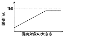
閾値決定部G42は、画像認識部F2が特定している衝突対象の大きさに応じて、低出力エリア用閾値ThXを決定する。例えば閾値決定部G42は、衝突対象の大きさに対応する低出力エリア用閾値ThXを示すデータ(以降、対応関係データ)と、画像認識部F2から提供される衝突対象の大きさとから、低出力エリア用閾値ThXを決定する。対応関係データはROM13に予め格納しておけばよい。対応関係データは、図11に示すように、衝突対象の大きさに応じた閾値を示すデータであればよく、衝突対象の大きさを変数とする関数として表されていても良いし、マップ形式で現れていても良い。少なくとも衝突対象の大きさが大きいほど、低出力エリア用閾値ThXが大きい値となるように定義されていれば良い。
The threshold determination unit G42 determines the low output area threshold ThX according to the size of the collision target specified by the image recognition unit F2. For example, the threshold determination unit G42 generates a low output from data indicating the low output area threshold ThX corresponding to the size of the collision target (hereinafter referred to as correspondence data) and the size of the collision target provided from the image recognition unit F2. An area threshold ThX is determined. The correspondence data may be stored in the
ただし、衝突対象の大きさが、小動物に対応するような大きさである場合には、衝突対象が人物である可能性は低い。衝突対象の大きさが、衝突対象が人物ではないと見なすことができる下限値以下である場合には、外部保護装置4を動作させる必要はない。したがって、対応関係データは、下限値以上の大きさに対応する閾値が定義されていれば良い。なお、衝突対象の大きさが下限値未満となっている場合には、例えば、外部保護装置4を動作させるための判定を実施しないなど、例外的に取り扱われれば良い。 However, if the size of the collision target is such that it corresponds to a small animal, the possibility that the collision target is a person is low. When the size of the collision target is equal to or lower than a lower limit value at which it can be considered that the collision target is not a person, it is not necessary to operate the external protection device 4. Accordingly, the correspondence relationship data only needs to define a threshold value corresponding to a size equal to or greater than the lower limit value. When the size of the collision target is less than the lower limit value, it may be handled exceptionally, for example, the determination for operating the external protection device 4 is not performed.
衝突対象の大きさは、衝突対象の路面に対する高さで評価されてもよいし、幅で評価されても良い。また、衝突対象の大きさは、高さと幅の両方で評価されても良い。下限値に相当する大きさとは、例えば、3〜5歳程度の子供を想定した大きさとすればよい。 The size of the collision target may be evaluated by the height of the collision target with respect to the road surface, or may be evaluated by the width. Further, the size of the collision target may be evaluated by both the height and the width. The size corresponding to the lower limit value may be a size assuming a child of about 3 to 5 years old, for example.
また、対応関係データは、衝突対象の大きさが大きいほど、低出力エリア用閾値ThXが大きい値となるように定義される一方、デフォルト閾値ThDを超過しないように設定されているものとする。例えば、低出力エリア用閾値ThXは、デフォルト閾値ThDよりも小さい所定の値に収束するように設定されていれば良い。低出力エリア用閾値ThXの最大値を収束値と称する。収束値は適宜設計されればよい。 Further, it is assumed that the correspondence relationship data is set so that the threshold value ThX for the low output area becomes larger as the size of the collision target is larger, while the default threshold value ThD is not exceeded. For example, the low output area threshold ThX only needs to be set to converge to a predetermined value smaller than the default threshold ThD. The maximum value of the low output area threshold ThX is referred to as a convergence value. The convergence value may be designed as appropriate.
なお、図11では、低出力エリア用閾値ThXは収束値に達するまで、衝突対象の大きさに比例して大きくなる態様を図示しているが、衝突対象の大きさと低出力エリア用閾値ThXの対応関係はこれに限らない。対数関数的に増加させてもよいし、階段状に増加させてもよい。 In FIG. 11, a mode in which the low output area threshold ThX increases in proportion to the size of the collision target until the convergence value is reached is illustrated, but the size of the collision target and the low output area threshold ThX are illustrated. The correspondence relationship is not limited to this. It may be increased logarithmically or may be increased stepwise.
以上で述べた閾値決定部G42が決定した低出力エリア用閾値ThXは、比較器Cmp5のマイナス側入力端子に入力される。つまり、この変形例3における比較器Cmp5は、衝突センサ3の出力値Pと、衝突対象の大きさに応じて定まる低出力エリア用閾値ThXを比較する。そして、衝突センサ3の出力値Pが低出力エリア用閾値ThXを超過している場合にAND素子Lc3にハイレベルを出力するように構成されている。
The low output area threshold ThX determined by the threshold determination unit G42 described above is input to the negative input terminal of the comparator Cmp5. That is, the comparator Cmp5 in the modified example 3 compares the output value P of the
以上の構成によれば、衝突位置が低出力エリアである場合、衝突対象の大きさに応じた閾値を用いて、外部保護装置4を動作させるか否かが判定される。したがって、より適切に外部保護装置4を動作させるか否かを判定することができ、外部保護装置4の誤作動を抑制することができる。 According to the above configuration, when the collision position is a low output area, it is determined whether or not to operate the external protection device 4 using a threshold value corresponding to the size of the collision target. Therefore, it can be determined whether or not the external protection device 4 is operated more appropriately, and malfunction of the external protection device 4 can be suppressed.
[変形例4]
ところで、保護対象とする人物の身長や姿勢、相対位置などによっては、衝突センサ3が衝突を検出することが困難な部分で1次衝突が発生する場合も生じうる。車両の前端部において衝突センサ3が衝突を検出することが困難な部分とは、例えば衝突センサ3が設けられていない部分等であって、具体的には、圧力チャンバ31よりも下方となる部分などである。
[Modification 4]
By the way, depending on the height, posture, relative position, etc. of the person to be protected, a primary collision may occur in a portion where it is difficult for the
そのような事情を鑑みると、車幅方向だけでなく、高さ方向においても低出力エリアが設定されていても良い。つまり、前端部における低出力エリアは3次元的に設定されていても良い。衝突センサ3が設けられていない部分、すなわち、衝突センサ3の出力値がほぼ0となるような部分も低出力エリアに含まれる。
In view of such circumstances, a low output area may be set not only in the vehicle width direction but also in the height direction. That is, the low output area at the front end may be set three-dimensionally. A portion where the
この変形例4の構成においては、動作判定部F4は、衝突位置が衝突センサ3が設けられていない部分となっている場合には、衝突センサ3の出力値Pが0であっても、外部保護装置4を動作させてもよい。例えば、衝突位置が衝突センサ3が設けられていない部分となっている場合には、低出力エリア用閾値を負の値に設定することで、論理的には、出力値Pを動作閾値以上とすることができる。
In the configuration of the modified example 4, when the collision position is a portion where the
[変形例5]
以上では、動作判定部F4が備える機能の一部をハードウェア的に実現する態様を例示したが、これに限らない。種々の回路素子に対応する処理は、ソフトウェア的に実現されても良い。また、動作判定部F4が備える機能の一部をソフトウェア的に実現する態様を例示したが、これに限らない。動作判定部F4全体がハードウェア的に実現されてもよい。
[Modification 5]
Although the aspect which implement | achieves a part of function with which operation | movement determination part F4 is provided above by hardware was illustrated above, it is not restricted to this. Processing corresponding to various circuit elements may be realized by software. Moreover, although the aspect which implement | achieves a part of function with which operation determination part F4 is provided in software was illustrated, it does not restrict to this. The entire operation determination unit F4 may be realized in hardware.
100 保護装置制御システム、1 ECU、2 カメラ、3 衝突センサ、4 外部保護装置、5 測距センサ、6 ラジエータ、11 CPU、12 RAM、13 ROM、31 圧力チャンバ、F1 衝突検知部(出力値取得部)、F2 画像認識部(物体認識部)、F3 衝突対象情報取得部、F31 衝突対象特定部、F32 衝突位置取得部、F4 動作判定部、F41 条件判定部、G41 衝突位置判定部、G42 閾値決定部、Cmp1〜5 比較器、Lc1〜3 AND素子、Ld1〜2 OR素子 100 protection device control system, 1 ECU, 2 camera, 3 collision sensor, 4 external protection device, 5 ranging sensor, 6 radiator, 11 CPU, 12 RAM, 13 ROM, 31 pressure chamber, F1 collision detection unit (output value acquisition) Part), F2 image recognition part (object recognition part), F3 collision target information acquisition part, F31 collision target identification part, F32 collision position acquisition part, F4 motion determination part, F41 condition determination part, G41 collision position determination part, G42 threshold Determination unit, Cmp1-5 comparator, Lc1-3 AND element, Ld1-2 OR element
Claims (10)
前記車両の前端部における他の物体との衝突を検知するための衝突センサの出力値を取得する出力値取得部(F1)と、
前記車両の前方に存在する物体についての情報を取得する物体認識部(F2)と、
前記物体認識部が取得している情報に基づいて、前記車両と衝突する対象である衝突対象及びその相対位置を特定する衝突対象特定部(F31)と、
前記衝突対象特定部が特定している前記衝突対象の相対位置に基づいて、前記車両の前端部において前記衝突対象が一次衝突する位置である衝突位置を推定する衝突位置取得部(F32)と、
前記出力値取得部が取得した前記出力値が、前記保護デバイスを作動させるための動作閾値よりも大きい値となっている場合に、前記保護デバイスを動作させる動作判定部(F4)と、を備え、
前記前端部のコーナー部が、前記前端部のうち、他の部分に比べて前記衝突センサの出力値が抑制される傾向にある部分である低出力エリアに設定されており、
前記動作判定部は、
前記衝突位置取得部が推定した前記衝突位置が、前記低出力エリアではない場合には、前記動作閾値として所定のデフォルト閾値を採用する一方、
前記衝突位置取得部が推定した前記衝突位置が、前記低出力エリアとなっている場合には、前記デフォルト閾値よりも小さい低出力エリア用閾値を、前記動作閾値として採用するとともに、
前記衝突位置取得部が推定した前記衝突位置が、前記衝突センサが設けられていない部分である場合には、前記出力値に変化がなくとも前記保護デバイスを動作させるように構成されている保護制御装置。 Used in vehicles equipped with protection devices to protect people who collide with the vehicle,
An output value acquisition unit (F1) for acquiring an output value of a collision sensor for detecting a collision with another object at the front end of the vehicle;
An object recognition unit (F2) for acquiring information about an object existing in front of the vehicle;
Based on the information acquired by the object recognition unit, a collision target identifying unit (F31) that identifies a collision target that is a target that collides with the vehicle and its relative position ;
Based on the relative position of the collision object the collision target identifying section is specified, the collision position acquiring unit that the collision object at the front end portion estimates the collision position is a position impinging primary of the vehicle and (F32),
An operation determination unit (F4) that operates the protection device when the output value acquired by the output value acquisition unit is larger than an operation threshold value for operating the protection device; ,
The corner portion of the front end portion is set to a low output area that is a portion in which the output value of the collision sensor tends to be suppressed compared to other portions of the front end portion,
The operation determination unit
When the collision position estimated by the collision position acquisition unit is not the low output area, a predetermined default threshold is adopted as the operation threshold,
When the collision position estimated by the collision position acquisition unit is the low output area, a threshold for the low output area smaller than the default threshold is adopted as the operation threshold ,
Protection control configured to operate the protection device even if the output value does not change when the collision position estimated by the collision position acquisition unit is a part where the collision sensor is not provided apparatus.
前記車両の前端部における他の物体との衝突を検知するための衝突センサの出力値を取得する出力値取得部(F1)と、
前記車両の前方に存在する物体についての情報を取得する物体認識部(F2)と、
前記物体認識部が取得している情報に基づいて、前記車両と衝突する対象である衝突対象及びその相対位置を特定する衝突対象特定部(F31)と、
前記衝突対象特定部が特定している前記衝突対象の相対位置に基づいて、前記車両の前端部において前記衝突対象が一次衝突する位置である衝突位置を推定する衝突位置取得部(F32)と、
前記出力値取得部が取得した前記出力値に基づいて前記保護デバイスの動作を制御する動作判定部(F4)と、を備え、
前記前端部のコーナー部が、前記前端部のうち、他の部分に比べて前記衝突センサの出力値が抑制される傾向にある部分である低出力エリアに設定されており、
前記動作判定部は、
前記衝突位置取得部が推定した前記衝突位置が、前記低出力エリアとなっている場合には、前記衝突位置が前記低出力エリアではない場合よりも小さい前記出力値で前記保護デバイスを動作させるとともに、
前記衝突位置取得部が推定した前記衝突位置が、前記衝突センサが設けられていない部分である場合には、前記出力値に変化がなくとも前記保護デバイスを動作させるように構成されている保護制御装置。 Used in vehicles equipped with protection devices to protect people who collide with the vehicle,
An output value acquisition unit (F1) for acquiring an output value of a collision sensor for detecting a collision with another object at the front end of the vehicle;
An object recognition unit (F2) for acquiring information about an object existing in front of the vehicle;
Based on the information acquired by the object recognition unit, a collision target identifying unit (F31) that identifies a collision target that is a target that collides with the vehicle and its relative position ;
Based on the relative position of the collision object the collision target identifying section is specified, the collision position acquiring unit that the collision object at the front end portion estimates the collision position is a position impinging primary of the vehicle and (F32),
An operation determination unit (F4) that controls the operation of the protection device based on the output value acquired by the output value acquisition unit;
The corner portion of the front end portion is set to a low output area that is a portion in which the output value of the collision sensor tends to be suppressed compared to other portions of the front end portion,
The operation determination unit
When the collision position estimated by the collision position acquisition unit is the low output area, the protection device is operated with the output value smaller than when the collision position is not the low output area. ,
Protection control configured to operate the protection device even if the output value does not change when the collision position estimated by the collision position acquisition unit is a part where the collision sensor is not provided apparatus.
前記低出力エリア用閾値として、前記衝突対象の移動体としての種別に応じた閾値を備え、
前記衝突対象特定部は、前記物体認識部が取得している情報に基づいて、前記衝突対象の移動体としての種別を判定し、
前記動作判定部は、前記衝突位置が前記低出力エリアである場合には、前記衝突対象の移動体としての種別に応じた閾値を前記動作閾値として採用することを特徴とする保護制御装置。 Oite to claim 1,
As the threshold for the low output area, comprising a threshold according to the type as the moving object of the collision target,
The collision target specifying unit determines the type of the collision target moving body based on the information acquired by the object recognition unit,
The said operation determination part employ | adopts the threshold value according to the classification as a mobile body of the said collision object as said operation | movement threshold value, when the said collision position is the said low output area.
前記低出力エリア用閾値として、前記低出力エリアに歩行者が衝突した場合を想定した歩行者用閾値を備え、
前記衝突対象特定部は、前記物体認識部が取得している情報に基づいて、前記衝突対象が歩行者であるか否かを判定し、
前記動作判定部は、前記衝突対象が歩行者であって、かつ、前記衝突位置が前記低出力エリアである場合には、前記歩行者用閾値を前記動作閾値として採用することを特徴とする保護制御装置。 Oite to claim 1 or 3,
As the low output area threshold, comprising a pedestrian threshold assuming the case where a pedestrian collides with the low output area,
The collision target specifying unit determines whether the collision target is a pedestrian based on information acquired by the object recognition unit,
The operation determining unit adopts the pedestrian threshold as the operation threshold when the collision target is a pedestrian and the collision position is the low output area. Control device.
前記低出力エリア用閾値として、前記低出力エリアに乗員が乗車している自転車が衝突した場合を想定した自転車用閾値を備え、
前記衝突対象特定部は、前記物体認識部が取得している情報に基づいて、前記衝突対象が、乗員が乗車している自転車である乗員付き自転車であるか否かを判定し、
前記動作判定部は、前記衝突対象が前記乗員付き自転車であって、かつ、前記衝突位置が前記低出力エリアである場合には、前記自転車用閾値を前記動作閾値として採用することを特徴とする保護制御装置。 In any one of Claims 1 , 3, and 4,
As the threshold for the low output area, a threshold for a bicycle assuming a case where a bicycle on which an occupant is riding collides with the low output area,
The collision target specifying unit determines whether the collision target is a bicycle with an occupant, which is a bicycle on which an occupant is riding, based on the information acquired by the object recognition unit.
The motion determination unit adopts the bicycle threshold value as the motion threshold value when the collision target is the bicycle with a passenger and the collision position is the low output area. Protection control device.
前記自転車用閾値は、前記低出力エリアに歩行者が衝突した場合を想定して設定される閾値よりも小さい値に設定されていることを特徴とする保護制御装置。 In claim 5,
The bicycle control threshold value is set to a value smaller than a threshold value set on the assumption that a pedestrian collides with the low output area.
前記自転車用閾値として、
前記低出力エリアにおいて前記乗員付き自転車が、前記車両の進行方向に対して前記乗員付き自転車の進行方向が垂直となる姿勢である横向き姿勢で衝突した場合を想定した横向き用閾値と、
前記低出力エリアにおいて前記乗員付き自転車が、前記車両の進行方向に対して前記乗員付き自転車の進行方向が平行となる姿勢である縦向き姿勢で衝突した場合を想定した閾値であって、前記横向き用閾値よりも小さい縦向き用閾値と、を備え、
前記動作判定部は、
前記衝突対象特定部が特定した前記衝突対象が前記乗員付き自転車である場合には、前記車両に対して前記乗員付き自転車の向きが前記縦向き姿勢となっているか前記横向き姿勢となっているかを判定し、
前記衝突対象としての前記乗員付き自転車が前記横向き姿勢となっている場合には、前記横向き用閾値を前記動作閾値として採用する一方、前記乗員付き自転車が前記縦向き姿勢となっている場合には、前記縦向き用閾値を前記動作閾値として採用することを特徴とする保護制御装置。 In claim 5 or 6,
As the bicycle threshold,
In the low output area, the bicycle with occupant assumes a sideways threshold that assumes a case in which the bicycle with the occupant collides in a sideways posture that is a posture in which the traveling direction of the occupant bicycle is perpendicular to the traveling direction of the vehicle;
In the low output area, the bicycle with the occupant is a threshold value assuming a case where the bicycle collides in a vertical posture that is a posture in which the traveling direction of the cyclist with the passenger is parallel to the traveling direction of the vehicle. A vertical orientation threshold value smaller than the use threshold value,
The operation determination unit
When the collision target specified by the collision target specifying unit is the bicycle with the occupant, whether the direction of the bicycle with the occupant is the vertical posture or the horizontal posture with respect to the vehicle. Judgment,
When the bicycle with the occupant as the collision target is in the lateral posture, the threshold for lateral orientation is adopted as the operation threshold, while when the bicycle with the occupant is in the vertical posture. The protection control device adopting the vertical threshold as the operation threshold.
前記低出力エリア用閾値は、前記衝突対象の大きさに応じた値が設定されており、
前記衝突対象特定部は、前記物体認識部が取得している情報に基づいて、前記衝突対象の大きさを取得し、
前記動作判定部は、前記衝突対象特定部が取得している前記衝突対象の大きさに応じた前記低出力エリア用閾値を前記動作閾値として採用することを特徴とする保護制御装置。 Oite to claim 1,
The threshold for the low output area is set to a value according to the size of the collision target,
The collision target specifying unit acquires the size of the collision target based on the information acquired by the object recognition unit,
The said operation determination part employ | adopts the said threshold value for low output areas according to the magnitude | size of the said collision object which the said collision object specific | specification part acquires as said operation | movement threshold value.
前記前端部において前照灯が配置されている部分、及び、フォグランプが配置されている部分の少なくとも何れか一方が前記低出力エリアに設定されていることを特徴とする保護制御装置。 In any one of Claim 1 to 8 ,
At least one of a portion where a headlamp is disposed and a portion where a fog lamp is disposed at the front end is set in the low output area.
前記衝突センサは、前記前端部において車幅方向に沿って配置されていることを特徴とする保護制御装置。 In any one of Claim 1 to 9,
The said collision sensor is arrange | positioned along the vehicle width direction in the said front-end part, The protection control apparatus characterized by the above-mentioned.
Priority Applications (4)
| Application Number | Priority Date | Filing Date | Title |
|---|---|---|---|
| JP2015204866A JP6555072B2 (en) | 2015-10-16 | 2015-10-16 | Protection control device |
| PCT/JP2016/079374 WO2017065045A1 (en) | 2015-10-16 | 2016-10-04 | Protection control device |
| DE112016004692.8T DE112016004692B4 (en) | 2015-10-16 | 2016-10-04 | Protective control device |
| US15/767,963 US20180304849A1 (en) | 2015-10-16 | 2016-10-04 | Protection control device |
Applications Claiming Priority (1)
| Application Number | Priority Date | Filing Date | Title |
|---|---|---|---|
| JP2015204866A JP6555072B2 (en) | 2015-10-16 | 2015-10-16 | Protection control device |
Publications (3)
| Publication Number | Publication Date |
|---|---|
| JP2017074919A JP2017074919A (en) | 2017-04-20 |
| JP2017074919A5 JP2017074919A5 (en) | 2017-12-14 |
| JP6555072B2 true JP6555072B2 (en) | 2019-08-07 |
Family
ID=58517221
Family Applications (1)
| Application Number | Title | Priority Date | Filing Date |
|---|---|---|---|
| JP2015204866A Active JP6555072B2 (en) | 2015-10-16 | 2015-10-16 | Protection control device |
Country Status (4)
| Country | Link |
|---|---|
| US (1) | US20180304849A1 (en) |
| JP (1) | JP6555072B2 (en) |
| DE (1) | DE112016004692B4 (en) |
| WO (1) | WO2017065045A1 (en) |
Families Citing this family (7)
| Publication number | Priority date | Publication date | Assignee | Title |
|---|---|---|---|---|
| JP6802053B2 (en) * | 2016-12-12 | 2020-12-16 | トヨタ自動車株式会社 | Vehicle peripheral monitoring device mounting structure |
| US11312324B2 (en) * | 2016-12-20 | 2022-04-26 | Pioneer Corporation | Accident determination device |
| JP6690601B2 (en) | 2017-06-07 | 2020-04-28 | 株式会社デンソー | Protection control device |
| JP6806018B2 (en) * | 2017-09-25 | 2020-12-23 | 株式会社デンソー | Protection control device and protection system |
| JP7125917B2 (en) * | 2019-05-31 | 2022-08-25 | 本田技研工業株式会社 | Vehicle protection device |
| JP7195219B2 (en) * | 2019-05-31 | 2022-12-23 | 本田技研工業株式会社 | Collision Prediction Judgment Device and Vulnerable Traffic Protection System |
| KR20210138289A (en) | 2020-05-12 | 2021-11-19 | 현대모비스 주식회사 | Apparatus for protecting waker and control method thereof |
Family Cites Families (16)
| Publication number | Priority date | Publication date | Assignee | Title |
|---|---|---|---|---|
| JP2004017812A (en) | 2002-06-17 | 2004-01-22 | Mazda Motor Corp | Collision protective device for vehicle |
| GB2400353A (en) * | 2003-04-09 | 2004-10-13 | Autoliv Dev | Pedestrian detecting system provided on a motor vehicle |
| KR20040094480A (en) * | 2003-05-02 | 2004-11-10 | 기아자동차주식회사 | Controlling Method of Unfolding Air Bag for Vehicle |
| JP4367088B2 (en) | 2003-10-29 | 2009-11-18 | 株式会社デンソー | Pedestrian discrimination device for vehicles |
| JP2007118831A (en) | 2005-10-28 | 2007-05-17 | Denso Corp | Colliding object discriminating device for vehicle and actuation system for pedestrian protecting device |
| JP4434293B2 (en) * | 2007-07-17 | 2010-03-17 | 株式会社デンソー | Vehicle collision detection device |
| JP2010036660A (en) * | 2008-08-01 | 2010-02-18 | Denso Corp | Collision protection system for vehicle |
| JP4831149B2 (en) | 2008-09-10 | 2011-12-07 | 株式会社デンソー | Vehicle collision detection device |
| JP4873068B2 (en) * | 2009-11-20 | 2012-02-08 | 株式会社デンソー | Collision damage reduction device |
| US8700257B2 (en) * | 2010-05-13 | 2014-04-15 | Toyota Motor Engineering & Manufacturing North America, Inc. | Control methodology of pedestrian kinematics using the active hood lift system |
| JP5825530B2 (en) | 2012-11-22 | 2015-12-02 | 株式会社デンソー | Vehicle collision detection device |
| JP5907182B2 (en) * | 2014-01-20 | 2016-04-26 | トヨタ自動車株式会社 | Pop-up hood device for vehicle |
| JP5949803B2 (en) * | 2014-02-07 | 2016-07-13 | トヨタ自動車株式会社 | Collision detection device |
| JP6090196B2 (en) * | 2014-02-10 | 2017-03-08 | トヨタ自動車株式会社 | Bumper structure for vehicles with pedestrian collision detection sensor |
| JP6149758B2 (en) * | 2014-02-21 | 2017-06-21 | トヨタ自動車株式会社 | Pedestrian collision detection system |
| JP2015204866A (en) | 2014-04-17 | 2015-11-19 | サミー株式会社 | Game machine |
-
2015
- 2015-10-16 JP JP2015204866A patent/JP6555072B2/en active Active
-
2016
- 2016-10-04 DE DE112016004692.8T patent/DE112016004692B4/en active Active
- 2016-10-04 US US15/767,963 patent/US20180304849A1/en not_active Abandoned
- 2016-10-04 WO PCT/JP2016/079374 patent/WO2017065045A1/en active Application Filing
Also Published As
| Publication number | Publication date |
|---|---|
| JP2017074919A (en) | 2017-04-20 |
| WO2017065045A1 (en) | 2017-04-20 |
| DE112016004692B4 (en) | 2021-10-14 |
| DE112016004692T5 (en) | 2018-06-28 |
| US20180304849A1 (en) | 2018-10-25 |
Similar Documents
| Publication | Publication Date | Title |
|---|---|---|
| JP6555072B2 (en) | Protection control device | |
| JP6337834B2 (en) | Protection control device | |
| WO2017006532A1 (en) | Protection control device | |
| US10573180B2 (en) | Vehicle control device and vehicle control method | |
| US9797734B2 (en) | Object recognition apparatus | |
| CN104276121B (en) | Control system, vehicle and the method for controlling security parameter of vehicle safety parameter | |
| EP3041714B1 (en) | System for controlling the deployment of an external safety device | |
| CN109891262B (en) | Object detecting device | |
| CN104709213A (en) | Apparatus and method for vehicle occupant protection in large animal collisions | |
| JP2013084242A (en) | Video-based warning system for vehicle | |
| JP2012008718A (en) | Obstacle avoiding apparatus | |
| JP2018118615A (en) | Occupant protection device for vehicle and occupant protection method for vehicle | |
| JP2008247111A (en) | Collision safety control system for vehicle | |
| JP6409736B2 (en) | Pop-up control device | |
| JP6794972B2 (en) | Protection control device | |
| JP2015205640A (en) | Vehicular collision control device | |
| WO2014171863A1 (en) | System for controlling the deployment of an external safety device | |
| SE1151023A1 (en) | Procedure and system for influencing collision consequences in a motor vehicle | |
| JP4171883B2 (en) | Collision prediction controller | |
| CN114364578A (en) | Method for adapting a triggering algorithm of a personal restriction device and control device for adapting a triggering algorithm of a personal restriction device | |
| SE1450739A1 (en) | System for controlling the deployment of an external safety device | |
| JP6806018B2 (en) | Protection control device and protection system | |
| KR101596995B1 (en) | Impact absorption method for vehicles | |
| JP7202790B2 (en) | Personnel protection system for vehicles | |
| KR102591195B1 (en) | Vehicle and method for controlling thereof |
Legal Events
| Date | Code | Title | Description |
|---|---|---|---|
| A521 | Request for written amendment filed |
Free format text: JAPANESE INTERMEDIATE CODE: A523 Effective date: 20171106 |
|
| A621 | Written request for application examination |
Free format text: JAPANESE INTERMEDIATE CODE: A621 Effective date: 20171106 |
|
| A131 | Notification of reasons for refusal |
Free format text: JAPANESE INTERMEDIATE CODE: A131 Effective date: 20181120 |
|
| A521 | Request for written amendment filed |
Free format text: JAPANESE INTERMEDIATE CODE: A523 Effective date: 20190118 |
|
| TRDD | Decision of grant or rejection written | ||
| A01 | Written decision to grant a patent or to grant a registration (utility model) |
Free format text: JAPANESE INTERMEDIATE CODE: A01 Effective date: 20190611 |
|
| A61 | First payment of annual fees (during grant procedure) |
Free format text: JAPANESE INTERMEDIATE CODE: A61 Effective date: 20190624 |
|
| R151 | Written notification of patent or utility model registration |
Ref document number: 6555072 Country of ref document: JP Free format text: JAPANESE INTERMEDIATE CODE: R151 |
|
| R250 | Receipt of annual fees |
Free format text: JAPANESE INTERMEDIATE CODE: R250 |
|
| R250 | Receipt of annual fees |
Free format text: JAPANESE INTERMEDIATE CODE: R250 |