JP6526600B2 - Piston type compressor - Google Patents

Piston type compressor Download PDF

Info

Publication number
JP6526600B2
JP6526600B2 JP2016096034A JP2016096034A JP6526600B2 JP 6526600 B2 JP6526600 B2 JP 6526600B2 JP 2016096034 A JP2016096034 A JP 2016096034A JP 2016096034 A JP2016096034 A JP 2016096034A JP 6526600 B2 JP6526600 B2 JP 6526600B2
Authority
JP
Japan
Prior art keywords
piston
compressor
discharge
support plate
drive shaft
Prior art date
Legal status (The legal status is an assumption and is not a legal conclusion. Google has not performed a legal analysis and makes no representation as to the accuracy of the status listed.)
Active
Application number
JP2016096034A
Other languages
Japanese (ja)
Other versions
JP2017203428A5 (en
JP2017203428A (en
Inventor
和弘 真島
和弘 真島
心吾 星崎
心吾 星崎
Current Assignee (The listed assignees may be inaccurate. Google has not performed a legal analysis and makes no representation or warranty as to the accuracy of the list.)
Koganei Corp
Original Assignee
Koganei Corp
Priority date (The priority date is an assumption and is not a legal conclusion. Google has not performed a legal analysis and makes no representation as to the accuracy of the date listed.)
Filing date
Publication date
Application filed by Koganei Corp filed Critical Koganei Corp
Priority to JP2016096034A priority Critical patent/JP6526600B2/en
Priority to PCT/JP2017/016080 priority patent/WO2017195576A1/en
Priority to TW106115703A priority patent/TW201740020A/en
Publication of JP2017203428A publication Critical patent/JP2017203428A/en
Publication of JP2017203428A5 publication Critical patent/JP2017203428A5/ja
Application granted granted Critical
Publication of JP6526600B2 publication Critical patent/JP6526600B2/en
Active legal-status Critical Current
Anticipated expiration legal-status Critical

Links

Images

Classifications

    • FMECHANICAL ENGINEERING; LIGHTING; HEATING; WEAPONS; BLASTING
    • F04POSITIVE - DISPLACEMENT MACHINES FOR LIQUIDS; PUMPS FOR LIQUIDS OR ELASTIC FLUIDS
    • F04BPOSITIVE-DISPLACEMENT MACHINES FOR LIQUIDS; PUMPS
    • F04B27/00Multi-cylinder pumps specially adapted for elastic fluids and characterised by number or arrangement of cylinders
    • F04B27/02Multi-cylinder pumps specially adapted for elastic fluids and characterised by number or arrangement of cylinders having cylinders arranged oppositely relative to main shaft
    • FMECHANICAL ENGINEERING; LIGHTING; HEATING; WEAPONS; BLASTING
    • F04POSITIVE - DISPLACEMENT MACHINES FOR LIQUIDS; PUMPS FOR LIQUIDS OR ELASTIC FLUIDS
    • F04BPOSITIVE-DISPLACEMENT MACHINES FOR LIQUIDS; PUMPS
    • F04B41/00Pumping installations or systems specially adapted for elastic fluids

Landscapes

  • Engineering & Computer Science (AREA)
  • Mechanical Engineering (AREA)
  • General Engineering & Computer Science (AREA)
  • Compressors, Vaccum Pumps And Other Relevant Systems (AREA)

Description

本発明は、ピストンの往復動により空気等の気体を圧縮するためのピストン式コンプレッサに関する。   The present invention relates to a piston compressor for compressing a gas such as air by reciprocating movement of a piston.

空気等の気体を圧縮するために使用されるコンプレッサには、ピストンの往復動によりポンプ室を膨張収縮させるようにしたピストン式がある。特許文献1には、4つのピストンを備えたピストン式コンプレッサが記載されている。このコンプレッサはピストンケースを有し、それぞれピストンが組み込まれる4つのシリンダ孔がピストンケース内に設けられ、4つのシリンダ孔は十字形に同一平面上に配置される。4つのシリンダ孔の中心部に配置されたカム部材が駆動軸に設けられている。駆動軸を回転駆動するための電動モータの主軸が駆動軸と同軸に連結されている。特許文献2には、それぞれピストンが設けられた4つのシリンダを備えた往復動圧縮機が記載されている。この往復動圧縮機においては、モータ軸に固定された偏心軸に4つのピストンが軸方向にずらしてシリンダに設けられている。   As a compressor used to compress a gas such as air, there is a piston type in which a pump chamber is expanded and contracted by reciprocating motion of a piston. Patent Document 1 describes a piston compressor having four pistons. This compressor has a piston case, and four cylinder holes in which the pistons are respectively incorporated are provided in the piston case, and the four cylinder holes are arranged in the same plane in a cruciform. A cam member disposed at the center of four cylinder holes is provided on the drive shaft. A main shaft of an electric motor for rotationally driving the drive shaft is coaxially connected to the drive shaft. Patent Document 2 describes a reciprocating compressor provided with four cylinders each provided with a piston. In this reciprocating compressor, four pistons are provided on the cylinder so as to be axially offset from an eccentric shaft fixed to the motor shaft.

特許文献3には2台のポンプを備えたポンプ機構が記載されている。このポンプ機構においては、ポンプ回転軸がベースに平行となるように、2台のポンプはベースの表面側に取り付けられ、ベースの背面側に電動モータが搭載されている。電動モータの駆動軸に取り付けられた駆動輪と、それぞれのポンプ軸に取り付けられたプーリとにはベルトが掛け渡されており、ベルトはベースに設けられた貫通孔を貫いている。特許文献4には、エアタンクに取り付けられる圧縮機本体を備えた往復動圧縮機が記載されている。この往復動圧縮機においては、圧縮機本体と電動モータが相互に平行となってエアタンクに取り付けられ、モータの駆動軸に取り付けられた駆動プーリと、圧縮機本体のクランク軸に取り付けられた従動プーリとにはベルトが掛け渡されている。   Patent Document 3 describes a pump mechanism provided with two pumps. In this pump mechanism, the two pumps are mounted on the surface side of the base so that the pump rotation axis is parallel to the base, and the electric motor is mounted on the back side of the base. A belt is stretched around a drive wheel attached to a drive shaft of the electric motor and a pulley attached to each pump shaft, and the belt passes through a through hole provided in the base. Patent Document 4 describes a reciprocating compressor provided with a compressor body attached to an air tank. In this reciprocating compressor, the compressor body and the electric motor are mounted parallel to each other on the air tank, and the driven pulley mounted on the drive shaft of the motor and the driven pulley mounted on the crankshaft of the compressor body A belt is stretched over the.

特許文献5には、ベルト駆動形往復圧縮機のベルトガードセットが記載されている。この圧縮機本体と電動モータとは相互に平行にベース等に取り付けられている。この圧縮機においては、往復動圧縮機の駆動軸に取り付けられるフライホイールプーリと、モータプーリとにはVベルトが掛け渡されており、それぞれのプーリとVベルトとを覆うベルトガードセットがそれぞれ分割モジュール化して樹脂成形される。   Patent Document 5 describes a belt guard set of a belt-driven reciprocating compressor. The compressor body and the electric motor are attached to a base or the like in parallel with each other. In this compressor, a V-belt is stretched around a flywheel pulley attached to a drive shaft of a reciprocating compressor and a motor pulley, and a belt guard set covering each pulley and the V-belt is a divided module. And resin molded.

特開2016−23555号公報JP, 2016-23555, A 特開2009−185789号公報JP, 2009-185789, A 特開平10−288159号公報JP 10-288159 A 特開2007−92680号公報JP 2007-92680 A 特開平8−270565号公報JP-A-8-270565

特許文献1に記載されるように、コンプレッサの駆動軸とこれを回転駆動するための電動モータの駆動軸とを同軸に配置すると、電動モータを含めたコンプレッサの軸方向寸法を小さくすることができない。また、特許文献2に記載されるように、4つのピストンを偏心軸に軸方向にずらして配置すると、モータを含めた往復動圧縮機の軸方向寸法を小さくすることができない。さらに、特許文献3に記載されるように、ベースの表面側に2台のポンプをポンプ回転軸がベースに平行となるように取り付け、ベースの背面側に電動モータを搭載するようにしたポンプ機構においても、ポンプ機構の上下方向の寸法を小さくすることができない。   As described in Patent Document 1, if the drive shaft of the compressor and the drive shaft of the electric motor for rotationally driving the same are coaxially arranged, the axial dimension of the compressor including the electric motor can not be reduced. . In addition, as described in Patent Document 2, when the four pistons are axially offset from the eccentric shaft, the axial dimension of the reciprocating compressor including the motor can not be reduced. Furthermore, as described in Patent Document 3, a pump mechanism in which two pumps are attached to the surface side of the base so that the pump rotation axis is parallel to the base and an electric motor is mounted on the back side of the base Also in the above, the vertical dimension of the pump mechanism can not be reduced.

特許文献4,5に記載された往復動圧縮機においても、電動モータと圧縮機本体とをエアタンク等の部材に取り付ける必要があり、電動モータを含めた圧縮機本体を小型化することができない。しかも、圧縮機本体に複数のシリンダを設けると、それぞれのシリンダに空気を供給する給気配管と、シリンダから吐出される吐出配管とを圧縮機本体の周囲に這い回す必要があり、往復動圧縮機の構造が複雑となる。さらに、それぞれの配管が圧縮機本体の駆動時に振動源となり、往復動圧縮機からの振動騒音が大きくなる。   Even in the reciprocating compressors described in Patent Documents 4 and 5, it is necessary to attach the electric motor and the compressor body to a member such as an air tank, and the compressor body including the electric motor can not be miniaturized. Moreover, when a plurality of cylinders are provided in the compressor body, it is necessary to wrap around the compressor body, the air supply piping for supplying air to each cylinder, and the discharge piping discharged from the cylinders. The structure of the aircraft becomes complicated. Furthermore, each pipe becomes a vibration source when the compressor body is driven, and vibration noise from the reciprocating compressor becomes large.

本発明の目的は、ピストン式コンプレッサの小型化および薄型化を図ることにある。   An object of the present invention is to reduce the size and thickness of a piston compressor.

本発明のピストン式コンプレッサは、ポンプ室を膨張収縮する複数のピストンが設けられたシリンダブロックと、それぞれ前記ピストンに対向して前記シリンダブロックの外周面に取り付けられ前記ポンプ室に連通する吸気連通孔および吐出連通孔が設けられた複数のアダプタと、前記ピストンを駆動する駆動軸とを有するコンプレッサ組立体を備えたピストン式コンプレッサであって、前記駆動軸を駆動する電動モータの主軸と前記駆動軸とが貫通し、前記シリンダブロック、それぞれの前記アダプタおよび前記電動モータが表面側に装着された支持プレートと、前記支持プレートの背面側に配置され、前記主軸の回転を前記駆動軸に伝達する動力伝達機構と、前記支持プレートを介して前記コンプレッサ組立体の背面に取り付けられ、前記吐出連通孔に連通しそれぞれの前記ポンプ室で圧縮された気体を被供給部材に供給する吐出流路が形成された流路部材と、を有する。 The piston compressor according to the present invention includes a cylinder block provided with a plurality of pistons for expanding and contracting the pump chamber, and an intake communication hole attached to the outer peripheral surface of the cylinder block opposite to the piston and communicating with the pump chamber. And a compressor assembly having a plurality of adapters provided with discharge communication holes and a drive shaft for driving the piston, wherein the main shaft of the electric motor for driving the drive shaft and the drive shaft And the support block on which the cylinder block, the respective adapters and the electric motor are mounted on the front side, and the back side of the support plate, the power for transmitting the rotation of the main shaft to the drive shaft a transmission mechanism mounted on a rear surface of the compressor assembly via the support plate, before The gas compressed in each of the pump chamber communicates with discharge passage having a flow path member which discharge channel is formed for supplying the supply target member.

コンプレッサ組立体と電動モータが支持プレートの表面側に装着され、電動モータの主軸の回転をコンプレッサ組立体の駆動軸に伝達するための動力伝達機構は支持プレートの背面側に配置されるので、支持プレートに垂直な方向におけるピストン式コンプレッサの厚み寸法を小さくすることができる。これにより、ピストン式コンプレッサを小型化および薄型化することができる。   Since the compressor assembly and the electric motor are mounted on the surface side of the support plate, and the power transmission mechanism for transmitting the rotation of the main shaft of the electric motor to the drive shaft of the compressor assembly is disposed on the back side of the support plate The thickness dimension of the piston compressor in the direction perpendicular to the plate can be reduced. Thereby, the piston compressor can be miniaturized and thinned.

一実施の形態であるピストン式コンプレッサの一方面側を示す斜視図である。It is a perspective view showing one side of a piston type compressor which is one embodiment. 図1の他方面側を示す斜視図である。It is a perspective view which shows the other surface side of FIG. 図1の一方面側を示す正面図である。It is a front view which shows the one surface side of FIG. 図2の他方面側を示す正面図である。It is a front view which shows the other surface side of FIG. 図1の左側面図である。It is a left view of FIG. 図5におけるA−A線拡大断面図である。It is the AA expanded sectional view in FIG. 図5におけるB−B線断面図である。It is the BB sectional drawing in FIG. 図3におけるC−C線拡大断面図である。It is the CC sectional view expanded line in FIG. 図8に示されたコンプレッサ組立体の斜視図である。FIG. 9 is a perspective view of the compressor assembly shown in FIG. 8; (A)は図3におけるD部拡大正面図であり、(B)は(A)の矢印E方向の側面図である。(A) is a D section enlarged front view in Drawing 3, and (B) is a side view of the arrow E direction of (A). (A)は図10(B)におけるF−F線断面図であり、(B)は(A)におけるG-G線断面図である。(A) is a cross-sectional view taken along the line F-F in FIG. 10 (B), and (B) is a cross-sectional view taken along the line G-G in (A). (A)は図11(B)における矢印H−H線断面図であり、(B)は(A)におけるI−I線断面図である。(A) is the arrow HH sectional view taken on the line in FIG.11 (B), (B) is the II sectional view taken on the line in (A). コンプレッサ組立体の変形例を示す正面図である。It is a front view showing a modification of a compressor assembly. 図13におけるJ−J線断面図である。It is a JJ sectional view taken on the line in FIG. 図14の斜視図である。It is a perspective view of FIG. 他の実施の形態であるピストン式コンプレッサの一方面側を示す斜視図である。It is a perspective view which shows one surface side of the piston type compressor which is other embodiment. 図16の他方面側を示す斜視図である。It is a perspective view which shows the other surface side of FIG. 図16の一方面側を示す正面図である。It is a front view which shows one side of FIG. 図17の他方面側を示す正面図である。It is a front view which shows the other surface side of FIG. 図16の左側面図である。It is a left view of FIG. 図20におけるK−K線断面図である。It is the KK sectional view taken on the line in FIG. 図20におけるL−L線断面図である。It is the LL sectional view in FIG. 図18におけるM−M線断面図である。It is the MM sectional view taken on the line in FIG.

以下、本発明の実施の形態を図面に基づいて詳細に説明する。それぞれの図においては、共通の機能を有する部材には、同一の符号が付されている。   Hereinafter, embodiments of the present invention will be described in detail based on the drawings. In each of the drawings, members having the same function are denoted by the same reference numerals.

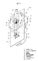
図1〜図5に示されるように、ピストン式コンプレッサ10aは長方形の支持プレート11を有する。コンプレッサ組立体12と電動モータ13が支持プレート11の一方面11aの側に装着される。電動モータ13は、アウターロータ型であり、電動モータ13の主軸14は支持プレート11を貫通して他方面11b側に突出し、駆動側回転体としての駆動プーリ15が主軸14の先端部に固定される。コンプレッサ組立体12の駆動軸16が支持プレート11を貫通して他方面11b側に突出し、従動側回転体としての従動プーリ17が駆動軸16の先端に固定される。明細書において、支持プレート11は、コンプレッサ組立体12と電動モータ13が装着される一方面11aを表面とし、反対側の他方面11bを背面とする。   As shown in FIGS. 1 to 5, the piston compressor 10 a has a rectangular support plate 11. The compressor assembly 12 and the electric motor 13 are mounted on the side of one surface 11 a of the support plate 11. The electric motor 13 is an outer rotor type, and the main shaft 14 of the electric motor 13 penetrates the support plate 11 and protrudes to the other surface 11 b side, and the drive pulley 15 as a drive side rotating body is fixed to the tip of the main shaft 14 Ru. The drive shaft 16 of the compressor assembly 12 penetrates the support plate 11 and protrudes to the other surface 11 b side, and a driven pulley 17 as a driven side rotating body is fixed to the tip of the drive shaft 16. In the specification, the support plate 11 has one surface 11a on which the compressor assembly 12 and the electric motor 13 are mounted as a surface, and the other surface 11b on the opposite side as a back surface.

動力伝達部材としてのタイミングベルト18が駆動プーリ15と従動プーリ17とに掛け渡され、タイミングベルト18を介して電動モータ13により駆動軸16が回転駆動される。駆動プーリ15および従動プーリ17の両方のプーリとタイミングベルト18は、支持プレート11の背面側に配置される。両方のプーリと、タイミングベルト18とにより、電動モータ13の主軸14の回転トルクを駆動軸16に伝達するための動力伝達機構19が形成される。流路部材20が支持プレート11の背面に取り付けられる。流路部材20は、図4に示されるように、従動プーリ17を囲むように支持プレート11の左右両側辺に沿って延在する平行部20aと、これらの平行部20aの一端部に一体となった連結部20bとを有している。流路部材20は、2つの平行部20aと1つの連結部20bとによって構成される。コンプレッサ組立体12から吐出された気体を外部に案内するための流路が、流路部材20に設けられている。流路部材20は横断面が四角形の部材により形成されており、流路部材20を支持プレート11に取り付けることにより、支持プレート11の強度が高められる。これにより、支持プレート11を薄い板材で構成することができる。   A timing belt 18 as a power transmission member is stretched around the drive pulley 15 and the driven pulley 17, and the drive shaft 16 is rotationally driven by the electric motor 13 via the timing belt 18. Both the drive pulley 15 and the driven pulley 17 and the timing belt 18 are disposed on the back side of the support plate 11. The power transmission mechanism 19 for transmitting the rotational torque of the main shaft 14 of the electric motor 13 to the drive shaft 16 is formed by both the pulleys and the timing belt 18. The flow path member 20 is attached to the back of the support plate 11. The flow path member 20 is, as shown in FIG. 4, integrally formed with parallel portions 20a extending along the left and right sides of the support plate 11 so as to surround the driven pulley 17, and one end of these parallel portions 20a. And the connecting portion 20b. The flow path member 20 is constituted by two parallel parts 20a and one connecting part 20b. A flow path for guiding the gas discharged from the compressor assembly 12 to the outside is provided in the flow path member 20. The flow passage member 20 is formed of a member having a square cross section, and by attaching the flow passage member 20 to the support plate 11, the strength of the support plate 11 is enhanced. Thereby, the support plate 11 can be comprised with a thin board | plate material.

図6および図8に示されるように、コンプレッサ組立体12はシリンダブロック21を備えており、シリンダブロック21は外周面が六角形となっている。カム収容室22がシリンダブロック21の中央部に設けられ、カム部材23がカム収容室22内に組み込まれる。カム部材23は駆動軸16に取り付けられ、カム部材23は駆動軸16により回転駆動される。図8に示されるように、駆動軸16の回転中心軸Oが支持プレート11に対して垂直方向に取り付けられ、支持プレート11の背面側に突出する。6つのシリンダ孔24が、シリンダブロック21にカム収容室22を横切り方向に設けられている。シリンダ孔24は、シリンダブロック21の外周面に沿う方向に60度置きに、シリンダブロック21に設けられている。6つのシリンダ孔24のうち、同軸状に設けられる2つのシリンダ孔24は対となっており、3対のシリンダ孔24がシリンダブロック21に設けられている。シリンダ孔24の中心軸は、駆動軸16の回転中心軸Oに対して直交する。シリンダ孔24は、内方端がカム収容室22に連通し、外方端がシリンダブロック21の外周面に開口する。   As shown in FIGS. 6 and 8, the compressor assembly 12 includes a cylinder block 21. The cylinder block 21 has a hexagonal outer peripheral surface. A cam chamber 22 is provided at the center of the cylinder block 21, and the cam member 23 is incorporated in the cam chamber 22. The cam member 23 is attached to the drive shaft 16, and the cam member 23 is rotationally driven by the drive shaft 16. As shown in FIG. 8, the rotation center axis O of the drive shaft 16 is attached vertically to the support plate 11 and protrudes on the back side of the support plate 11. Six cylinder holes 24 are provided in the cylinder block 21 in a direction crossing the cam storage chamber 22. The cylinder holes 24 are provided in the cylinder block 21 at an angle of 60 degrees in a direction along the outer peripheral surface of the cylinder block 21. Of the six cylinder holes 24, two coaxially provided cylinder holes 24 are paired, and three pairs of cylinder holes 24 are provided in the cylinder block 21. The central axis of the cylinder bore 24 is orthogonal to the rotational center axis O of the drive shaft 16. An inner end of the cylinder hole 24 communicates with the cam storage chamber 22, and an outer end of the cylinder hole 24 opens to the outer peripheral surface of the cylinder block 21.

シリンダブロック21は6つの装着面25を有し、シリンダ孔24の外方端は装着面25に開口している。アダプタ26がそれぞれの装着面25にねじ部材27により取り付けられる。アダプタ26は、装着面25に当接される磁石ホルダ28と、磁石ホルダ28に取り付けられる流路プレート29とを有している。磁石ホルダ28と流路プレート29は、それぞれ樹脂やアルミニウム合金等の非磁性材料により形成される。   The cylinder block 21 has six mounting surfaces 25, and the outer end of the cylinder bore 24 is open to the mounting surface 25. Adapters 26 are attached to their respective mounting surfaces 25 by means of threaded members 27. The adapter 26 has a magnet holder 28 in contact with the mounting surface 25 and a flow path plate 29 attached to the magnet holder 28. The magnet holder 28 and the flow path plate 29 are each formed of a nonmagnetic material such as a resin or an aluminum alloy.

ピストン31がそれぞれのシリンダ孔24に往復動自在に装着され、シリンダブロック21は6つのピストン31を有している。ピストン31は、樹脂やアルミニウム合金等の非磁性材料により形成される。ピストン31の頂部はアダプタ26に対向し、ピストン31の底部はカム部材23に対向する。ポンプ室32がピストン31とアダプタ26の磁石ホルダ28とにより区画される。ピストン31がアダプタ26に向けて移動するとポンプ室32は収縮し、ピストン31がカム部材23に向けて移動するとポンプ室32は膨張する。6つのピストン31のうち、同軸状に配置される2つのピストン31は対となっている。   The pistons 31 are mounted reciprocally in the respective cylinder bores 24, and the cylinder block 21 has six pistons 31. The piston 31 is formed of a nonmagnetic material such as resin or aluminum alloy. The top of the piston 31 faces the adapter 26, and the bottom of the piston 31 faces the cam member 23. The pump chamber 32 is partitioned by the piston 31 and the magnet holder 28 of the adapter 26. When the piston 31 moves toward the adapter 26, the pump chamber 32 contracts, and when the piston 31 moves toward the cam member 23, the pump chamber 32 expands. Of the six pistons 31, two coaxially arranged pistons 31 are paired.

永久磁石からなるピストン磁石33がそれぞれのピストン31の頂部に埋め込まれている。ピストン磁石33は、ピストン31の頂部に露出しアダプタ26に対向する対向面を有している。永久磁石からなるアダプタ磁石34が磁石ホルダ28に設けられている。アダプタ磁石34は、磁力発生部材を構成しており、磁石ホルダ28に埋め込まれ、磁石ホルダ28の内面に露出してピストン磁石33の露出面に対向する対向面を有している。アダプタ磁石34は、図6および図8に示されるように、長方形の棒状となっており、駆動軸16に平行に配置される。アダプタ磁石34の形状は、長方形の棒状に限られず、円柱状または楕円でもよい。   A piston magnet 33 consisting of a permanent magnet is embedded in the top of each piston 31. The piston magnet 33 has a facing surface exposed at the top of the piston 31 and facing the adapter 26. An adapter magnet 34 consisting of a permanent magnet is provided on the magnet holder 28. The adapter magnet 34 constitutes a magnetic force generating member, is embedded in the magnet holder 28, and has an opposing surface exposed to the inner surface of the magnet holder 28 and opposed to the exposed surface of the piston magnet 33. The adapter magnet 34 is in the shape of a rectangular bar as shown in FIGS. 6 and 8 and is disposed parallel to the drive shaft 16. The shape of the adapter magnet 34 is not limited to a rectangular bar, and may be cylindrical or elliptical.

アダプタ磁石34の対向面は、ピストン磁石33の対向面と同極性となっている。これにより、アダプタ磁石34は、ピストン磁石33に対して反発する磁力を加え、ピストン31にポンプ室32を膨張させる方向の推力つまり膨張磁力を加える。   The opposing surface of the adapter magnet 34 has the same polarity as the opposing surface of the piston magnet 33. Thereby, the adapter magnet 34 applies a magnetic force that repels the piston magnet 33, and applies a thrust in a direction to expand the pump chamber 32, ie, an expansion magnetic force, to the piston 31.

図6および図8に示されるように、回転体35がそれぞれのピストン31の底部に回転自在に装着される。回転体35は、ピストン31に取り付けられる支持ピン36により支持される。回転体35としては、ボール軸受が用いられており、支持ピン36に固定される内側環状部材と、その外側に多数のボールを介して回転自在に装着される外側環状部材とを有している。   As shown in FIGS. 6 and 8, a rotary body 35 is rotatably mounted on the bottom of each piston 31. The rotating body 35 is supported by a support pin 36 attached to the piston 31. A ball bearing is used as the rotating body 35, and has an inner annular member fixed to the support pin 36, and an outer annular member rotatably mounted on the outside through a large number of balls. .

カム面37がカム部材23の外周面に設けられており、カム面37は、回転体35の外周面に転がり接触する。カム面37は、図6に示されるように、最大半径の2つの長径部と、最小半径の2つの短径部とを有し、ピストン31の移動軌跡がサイン曲線となるような形状である。カム部材23が駆動軸16により回転駆動されると、ピストン31は、アダプタ26に最も近づく位置から最も遠ざかる位置との間を往復動する。駆動軸16は、図8に示されるように、シリンダブロック21に取り付けられた軸受38に回転自在に支持される。   The cam surface 37 is provided on the outer peripheral surface of the cam member 23, and the cam surface 37 is in rolling contact with the outer peripheral surface of the rotating body 35. The cam surface 37, as shown in FIG. 6, has a shape such that the movement trajectory of the piston 31 is a sine curve, having two major diameter portions with the largest radius and two minor diameter portions with the smallest radius. . When the cam member 23 is rotationally driven by the drive shaft 16, the piston 31 reciprocates between the position closest to the adapter 26 and the position farthest from the position. The drive shaft 16 is rotatably supported by bearings 38 mounted on the cylinder block 21 as shown in FIG.

図6においては、カッコ書きで符号a、bが付された2つのピストン31(a)、31(b)は対となっており、2つのピストン31(a)、31(b)の回転体35がカム面37の長径部に転がり接触した状態を示す。このときには、2つのピストン31(a)、31(b)は、アダプタ26に最も近づく。この最も近づく位置に向けてピストン31が移動するときには、ピストン磁石33とアダプタ磁石34との反発力に抗して2つのピストン31(a)、31(b)がアダプタ26に向けて移動し、ポンプ室32が収縮される。   In FIG. 6, two pistons 31 (a) and 31 (b), which are indicated by brackets a and b in parentheses, are paired, and the rotating bodies of the two pistons 31 (a) and 31 (b) 35 shows a state of rolling contact with the major diameter portion of the cam surface 37. FIG. At this time, the two pistons 31 (a), 31 (b) come closest to the adapter 26. When the piston 31 moves toward the closest position, the two pistons 31 (a) and 31 (b) move toward the adapter 26 against the repulsive force of the piston magnet 33 and the adapter magnet 34, The pump chamber 32 is contracted.

カム部材23が図6に示される位置から90度回転すると、カム面37の短径部が2つのピストン31(a)、31(b)の回転体35と転がり接触する。このときには、2つのピストン31(a)、31(b)は、アダプタ26から最も遠ざかる。カム面37の長径部が回転体35に接触した位置から短径部が接触する位置に向けてカム部材23が回転するときには、ピストン磁石33とアダプタ磁石34との反発力により、ピストン31はアダプタ26に対して最も近づく位置から最も遠ざかる位置に移動する。これにより、ポンプ室32が膨張する。他の対のピストン31についても同様である。   When the cam member 23 is rotated 90 degrees from the position shown in FIG. 6, the short diameter portion of the cam surface 37 makes rolling contact with the rotating bodies 35 of the two pistons 31 (a), 31 (b). At this time, the two pistons 31 (a), 31 (b) are the farthest from the adapter 26. When the cam member 23 rotates from the position where the major diameter portion of the cam surface 37 contacts the rotating body 35 toward the position where the minor diameter portion contacts, the piston 31 is an adapter due to the repulsive force between the piston magnet 33 and the adapter magnet 34 Move to the position farthest away from the position closest to 26. Thereby, the pump chamber 32 is expanded. The same applies to the other pairs of pistons 31.

このように、アダプタ磁石34がそれぞれのピストン31に対してポンプ室32を膨張させる方向の磁力を加えた状態のもとで、カム部材23のカム面37と回転体35との転がり接触により、ピストン31は直線往復動する。つまり、カム部材23とピストン31は滑り接触することがない。これにより、カム面37の摩耗発生が防止されて、カム部材23を高速回転させても、コンプレッサ組立体12の高い耐久性を維持できる。   In this manner, the rolling contact between the cam surface 37 of the cam member 23 and the rotary body 35 in a state where the adapter magnet 34 applies a magnetic force in the direction to expand the pump chamber 32 to each piston 31 The piston 31 reciprocates linearly. That is, the cam member 23 and the piston 31 do not make sliding contact. As a result, the occurrence of wear of the cam surface 37 is prevented, and the high durability of the compressor assembly 12 can be maintained even if the cam member 23 is rotated at high speed.

さらに、対をなすピストン31は同時に外側に向けて、または2つ同時に内側に向けて動くので、対をなす2つのピストン31の重心は偏心することなく一定位置を保つ。したがって、6つのピストン31の動的バランスが高められ、振動発生を抑制しつつ高速動作させることが可能となる。   Furthermore, since the paired pistons 31 simultaneously move outward or two simultaneously inward, the centers of gravity of the two paired pistons 31 maintain a constant position without eccentricity. Therefore, the dynamic balance of the six pistons 31 is enhanced, and it is possible to operate at high speed while suppressing the occurrence of vibration.

全てのシリンダ孔24の中心軸は1点で交差しているので、1つのカム部材23によって全てのピストン31を駆動することができる。さらに、それぞれのピストン31は駆動軸16に対して直角方向に往復動する。したがって、シリンダブロック21の駆動軸16の方向の寸法を小さくすることができる。このように、小型のシリンダブロック21により所望のポンプ室容積を得ることができるので、コンプレッサ10aを小型化することができる。   Since the central axes of all the cylinder bores 24 intersect at one point, one cam member 23 can drive all the pistons 31. Furthermore, each piston 31 reciprocates in a direction perpendicular to the drive shaft 16. Accordingly, the dimension of the cylinder block 21 in the direction of the drive shaft 16 can be reduced. As described above, since the desired pump chamber volume can be obtained by the small cylinder block 21, the compressor 10a can be miniaturized.

しかも、電動モータ13はアウターロータ型であり、図5に示されるように、電動モータ13の主軸14の軸方向における厚み寸法は、シリンダブロック21の厚み寸法に近くなっている。コンプレッサ組立体12は電動モータ13の径方向外方に配置されて支持プレート11の表面側に装着され、駆動軸16と主軸14とが平行に配置されて支持プレート11を貫通する。また、動力伝達機構19は支持プレート11の背面側に配置される。したがって、駆動軸16と主軸14とを同軸状に配置する形態と相違して、本発明においてはコンプレッサ10aの駆動軸16の軸方向の寸法つまり厚み寸法は小さいので、コンプレッサ10aを小型化、薄型化することができる。   Moreover, the electric motor 13 is an outer rotor type, and as shown in FIG. 5, the thickness dimension in the axial direction of the main shaft 14 of the electric motor 13 is close to the thickness dimension of the cylinder block 21. The compressor assembly 12 is disposed radially outward of the electric motor 13 and mounted on the surface side of the support plate 11, and the drive shaft 16 and the main shaft 14 are disposed in parallel and penetrate the support plate 11. Also, the power transmission mechanism 19 is disposed on the back side of the support plate 11. Therefore, unlike the embodiment in which the drive shaft 16 and the main shaft 14 are coaxially arranged, in the present invention, the axial dimension of the drive shaft 16 of the compressor 10a, that is, the thickness dimension is small. Can be

さらに、主軸14を駆動軸16に同軸状に連結する形態の場合には、主軸14の回転を円滑に駆動軸16に伝達するために、両方の軸の組立精度を高める必要がある。これに対して、本発明においては、主軸14と駆動軸16を平行配置にすることにより、主軸14と駆動軸16の平行度に誤差が発生しても、その誤差をタイミングベルト18により吸収することができる。これにより、コンプレッサ組立体12と電動モータ13の組立精度を高める必要がなく、コンプレッサ10aの組立作業性を高めることができる。また、駆動プーリ15と従動プーリ17との径を相違させることにより、モータ回転数を変化させることなく、駆動軸16の回転数や回転トルクが相違する多種類のコンプレッサ10aを組み立てることができる。なお、動力伝達部材としてのタイミングベルト18に代えて、Vベルトや平ベルトを使用したり、チェーンを使用したりすることもできる。チェーンが使用されるときには、駆動プーリ15と従動プーリ17に代えてスプロケットが回転体として使用される。   Furthermore, in the case where the main shaft 14 is coaxially coupled to the drive shaft 16, in order to smoothly transmit the rotation of the main shaft 14 to the drive shaft 16, it is necessary to improve the assembly accuracy of both shafts. On the other hand, in the present invention, by arranging the main shaft 14 and the drive shaft 16 in parallel, even if an error occurs in the parallelism between the main shaft 14 and the drive shaft 16, the error is absorbed by the timing belt 18. be able to. As a result, it is not necessary to increase the assembly accuracy of the compressor assembly 12 and the electric motor 13, and the assembly workability of the compressor 10a can be improved. Further, by making the diameters of the drive pulley 15 and the driven pulley 17 different, it is possible to assemble many types of compressors 10a having different rotational speeds and rotational torques of the drive shaft 16 without changing the motor rotational speed. In place of the timing belt 18 as a power transmission member, a V-belt or a flat belt may be used, or a chain may be used. When a chain is used, a sprocket is used as a rotating body instead of the drive pulley 15 and the driven pulley 17.

駆動軸16が電動モータ13により回転駆動されて、ポンプ室32がピストン31によって膨張されると、外部から気体がポンプ室32に供給される。一方、ポンプ室32がピストン31によって収縮されると、ポンプ室32内の気体が外部に吐出される。図8に示されるように、息付き孔40がシリンダブロック21に設けられ、ポンプ室32の膨張収縮に伴って外気が給排される。   When the drive shaft 16 is rotationally driven by the electric motor 13 and the pump chamber 32 is expanded by the piston 31, gas is supplied to the pump chamber 32 from the outside. On the other hand, when the pump chamber 32 is contracted by the piston 31, the gas in the pump chamber 32 is discharged to the outside. As shown in FIG. 8, a breathing hole 40 is provided in the cylinder block 21, and outside air is supplied and discharged as the pump chamber 32 expands and contracts.

図10(A)は図3におけるD部拡大正面図であり、アダプタ26を拡大して示す。図10(B)は図10(A)における矢印E方向から見たアダプタ26の外面を示す側面図である。図11(A)は図10(B)におけるF−F線断面図であり、アダプタ26の断面を示す。図11(B)は図11(A)におけるG-G線断面図であり、磁石ホルダ28の内面を示す。図12(A)は図11(B)における矢印H−H線断面図であり、図12(B)は図12(A)におけるI−I線断面図である。   FIG. 10A is an enlarged front view of a portion D in FIG. 3 and shows the adapter 26 in an enlarged manner. FIG. 10 (B) is a side view showing the outer surface of the adapter 26 as viewed in the direction of arrow E in FIG. 10 (A). FIG. 11A is a cross-sectional view taken along the line F-F in FIG. 10B and shows a cross section of the adapter 26. FIG. 11B is a cross-sectional view taken along the line GG in FIG. 11A, showing the inner surface of the magnet holder 28. As shown in FIG. 12A is a cross-sectional view taken along the line HH in FIG. 11B, and FIG. 12B is a cross-sectional view taken along the line I-I in FIG.

図3において、符号aがカッコ書きで示されたアダプタ26(a)は、図6および図8に示されたピストン31(a)に対向し、符号bがカッコ書きで示されたアダプタ26(b)は、ピストン31(b)に対向する。   In FIG. 3, the adapter 26 (a) indicated by the symbol a in parentheses is opposed to the piston 31 (a) shown in FIGS. 6 and 8, and the adapter 26 indicated by the symbol b in parentheses ( b) faces the piston 31 (b).

図11(A)に示されるように、それぞれポンプ室32に連通する吸気孔41と、吐出孔42が磁石ホルダ28に設けられている。吸気孔41は流路プレート29に設けられた吸気連通孔43に連通し、吐出孔42は流路プレート29に設けられた吐出連通孔44に連通する。吸気連通孔43と吐出連通孔44は、図12(A)に示されるように、流路プレート29の取付面45に開口する。取付面45は支持プレート11の表面に密着して取り付けられる。吸気連通孔43は、図4および図7に示されるように、支持プレート11に設けられた吸気ポート46を介して外気に連通する。図6に示した対をなす2つのピストン31(a)、31(b)のポンプ室32に連通する吸気連通孔43は、流路部材20を貫通する吸気ポート46を介して外部に連通する。他のピストン31のポンプ室32は、支持プレート11に設けられた吸気ポート46により外部に直接連通する。 As shown in FIG. 11A, an intake hole 41 communicating with the pump chamber 32 and a discharge hole 42 are provided in the magnet holder 28. The intake holes 41 communicate with the intake communication holes 43 provided in the flow passage plate 29, and the discharge holes 42 communicate with the discharge communication holes 44 provided in the flow passage plate 29. The intake communication hole 43 and the discharge communication hole 44 open in the mounting surface 45 of the flow path plate 29, as shown in FIG. 12A. The mounting surface 45 is closely attached to the surface of the support plate 11. The intake communication hole 43 communicates with the outside air through an intake port 46 provided in the support plate 11 as shown in FIGS. 4 and 7. The intake communication hole 43 communicating with the pump chamber 32 of the two pistons 31 (a) and 31 (b) forming a pair shown in FIG. 6 communicates with the outside through the intake port 46 penetrating the flow path member 20 . The pump chamber 32 of the other piston 31 directly communicates with the outside through an intake port 46 provided on the support plate 11.

一方、吐出連通孔44は、図7に示されるように、支持プレート11を貫通し、流路部材20に設けられた吐出孔47に連通する。それぞれの吐出孔47は、流路部材20に設けられた吐出流路48に連通しており、全てのポンプ室32から吐出された気体は、吐出流路48の吐出ポート49から外部に供給される。吐出ポート49に連通する継手50が流路部材20に取り付けられ、図示しないホースやパイプ等からなる配管が継手50に取り付けられる。それぞれのポンプ室32から吐出された気体は、配管により被供給部材に供給される。   On the other hand, as shown in FIG. 7, the discharge communication holes 44 penetrate the support plate 11 and communicate with the discharge holes 47 provided in the flow path member 20. Each discharge hole 47 communicates with the discharge flow path 48 provided in the flow path member 20, and the gas discharged from all the pump chambers 32 is supplied to the outside from the discharge port 49 of the discharge flow path 48. Ru. A joint 50 communicating with the discharge port 49 is attached to the flow path member 20, and a piping made of a hose, a pipe or the like not shown is attached to the joint 50. The gas discharged from each pump chamber 32 is supplied to the supply target member by piping.

このように、全てのポンプ室32から吐出される気体を1つの流路部材20に集合させて外部に案内するようにしたので、シリンダブロック21に複数本の配管を設けることが不要となり、コンプレッサ10aを小型化することができる。   As described above, since the gas discharged from all the pump chambers 32 is gathered in one flow path member 20 and guided to the outside, it becomes unnecessary to provide a plurality of pipes in the cylinder block 21, and the compressor 10a can be miniaturized.

図11(A)に示されるように、吸気用の逆止弁51が吸気孔41に装着され、吐出用の逆止弁52が吐出孔42に装着される。それぞれの逆止弁51,52は、図11(A)に示されるように、磁石ホルダ28に取り付けられる基部53と、これよりも大径の弾性変形部54とを有している。吸気用の逆止弁51は、ポンプ室32が膨張するときには吸気孔41を開放する。これにより、吸気ポート46から流入した気体である外気がポンプ室32に供給される。これに対し、ポンプ室32が収縮するときには逆止弁51は吸気孔41を閉じる。一方、吐出用の逆止弁52は、ポンプ室32が膨張するときには吐出孔42を閉じる。これに対し、ポンプ室32が収縮するときには、吐出用の逆止弁52は吐出孔42を開放する。これにより、全てのポンプ室32から吐出された気体は、吐出ポート49から外部に吐出される。   As shown in FIG. 11A, a check valve 51 for suction is mounted in the suction hole 41, and a check valve 52 for discharge is mounted in the discharge hole. As shown in FIG. 11A, each of the check valves 51 and 52 has a base 53 attached to the magnet holder 28 and an elastically deformable portion 54 larger in diameter than this. The suction check valve 51 opens the suction hole 41 when the pump chamber 32 is expanded. Thus, the outside air, which is a gas flowing from the intake port 46, is supplied to the pump chamber 32. On the other hand, when the pump chamber 32 contracts, the check valve 51 closes the intake hole 41. On the other hand, the discharge check valve 52 closes the discharge hole 42 when the pump chamber 32 expands. On the other hand, when the pump chamber 32 contracts, the check valve 52 for discharge opens the discharge hole 42. Thereby, the gas discharged from all the pump chambers 32 is discharged from the discharge port 49 to the outside.

なお、吸気ポート46は、支持プレート11の背面側で外部に開口しているが、吸気孔41に連通する吸気ポートを流路プレート29に設けても良い。その場合には、外気が支持プレート11の表面側からポンプ室32に吸入される。   Although the intake port 46 is opened to the outside on the back surface side of the support plate 11, an intake port communicating with the intake hole 41 may be provided in the flow path plate 29. In that case, the outside air is drawn into the pump chamber 32 from the surface side of the support plate 11.

図13は、変形例であるコンプレッサ組立体12aを示す正面図であり、図14は図13におけるJ−J線断面図であり、図15は図14の斜視図である。コンプレッサ組立体12aは、上述したコンプレッサ組立体12と同様に、支持プレート11の表面側に装着され、コンプレッサ組立体12aの径方向外方に位置させて電動モータ13が支持プレート11の表面側に装着される。電動モータ13の回転トルクは、上述した場合と同様に、支持プレート11の背面側に配置される動力伝達機構19により駆動軸16に伝達される。シリンダブロック21とこれに組み込まれるピストン31等の構造は、図1〜図9に示したコンプレッサ組立体12と同様であり、重複した説明は省略する。   13 is a front view showing a compressor assembly 12a which is a modification, FIG. 14 is a cross-sectional view taken along the line J-J in FIG. 13, and FIG. 15 is a perspective view of FIG. The compressor assembly 12a is mounted on the surface side of the support plate 11 in the same manner as the compressor assembly 12 described above, and is positioned radially outward of the compressor assembly 12a so that the electric motor 13 is on the surface side of the support plate 11. It is attached. The rotational torque of the electric motor 13 is transmitted to the drive shaft 16 by the power transmission mechanism 19 disposed on the back side of the support plate 11 as described above. The structures of the cylinder block 21 and the pistons 31 and the like incorporated therein are the same as those of the compressor assembly 12 shown in FIGS. 1 to 9, and redundant description will be omitted.

コンプレッサ組立体12aは、上述したコンプレッサ組立体12と同様に、6つのシリンダ孔24が設けられたシリンダブロック21を有している。アダプタ26aが6つの装着面25に装着され、磁力発生部材としてのソレノイド55がアダプタ26aに設けられている。ソレノイド55は、鉄心56が組み込まれたボビン57を有し、ボビン57の外側にはコイル58が巻き付けられている。図14に示されるように、コイル58の接続端子59がアダプタ26aの外部に突出しており、接続端子59に接続される図示しない給電プラグを介して、外部からコイル58に電力が供給される。   The compressor assembly 12a has a cylinder block 21 provided with six cylinder holes 24 in the same manner as the compressor assembly 12 described above. The adapter 26a is mounted on the six mounting surfaces 25, and a solenoid 55 as a magnetic force generating member is provided on the adapter 26a. The solenoid 55 has a bobbin 57 in which an iron core 56 is incorporated, and a coil 58 is wound around the bobbin 57. As shown in FIG. 14, the connection terminal 59 of the coil 58 protrudes to the outside of the adapter 26 a, and power is supplied to the coil 58 from the outside via a power supply plug (not shown) connected to the connection terminal 59.

図13〜図15に示したコンプレッサ組立体12aを有するピストン式コンプレッサにおいては、電力がコイル58に供給され、ソレノイド55は、ピストン磁石33に対して反発する磁力を発生する。これにより、それぞれポンプ室32を膨張させる方向の推力つまり膨張磁力が複数のピストン31に加えられる。このコンプレッサ組立体12aにおいては、コイル58に対する電力量や通電タイミングを制御することにより、ソレノイド55によりピストン磁石33に加えられる反発力の強度と、磁力を発生させるタイミングとをカム部材23の回転位置に応じて変化させることができる。   In the piston-type compressor having the compressor assembly 12a shown in FIGS. 13-15, power is supplied to the coil 58, and the solenoid 55 generates a magnetic force that repels the piston magnet 33. As a result, the thrust in the direction in which the pump chamber 32 is expanded, that is, the expansion magnetic force is applied to the plurality of pistons 31. In this compressor assembly 12a, the intensity of the repulsive force applied to the piston magnet 33 by the solenoid 55 and the timing for generating the magnetic force are controlled by controlling the amount of electric power and the energization timing to the coil 58, and the rotational position of the cam member 23. It can be changed accordingly.

上述したアダプタ26が磁石ホルダ28と流路プレート29とにより形成されているのに対し、アダプタ26aはソレノイド55が組み込まれるブロック材を有している。このブロック材には、図10〜図12に示した吸気孔41や吐出孔42等が設けられており、ポンプ室32には外部から空気が供給され、圧縮された気体は流路部材20の吐出ポート49から外部に吐出される。   While the adapter 26 described above is formed of the magnet holder 28 and the flow path plate 29, the adapter 26a has a block material in which the solenoid 55 is incorporated. This block is provided with the intake holes 41 and the discharge holes 42 shown in FIGS. 10 to 12, and the pump chamber 32 is supplied with air from the outside, and the compressed gas flows in the flow path member 20. The ink is discharged from the discharge port 49 to the outside.

図16〜図23は、他の実施の形態であるピストン式コンプレッサ10bを示す。このコンプレッサ10bは、上述したコンプレッサ10aが単体のコンプレッサ組立体12を有しているのに対し、第1と第2の2つのコンプレッサ組立体12bを有している。両方のコンプレッサ組立体12bは、支持プレート11の表面に装着され、支持プレート11の表面に装着される電動モータ13により駆動される。コンプレッサ組立体12と同様に、駆動側回転体としての駆動プーリ15が電動モータ13の主軸14に装着され、従動側回転体としての従動プーリ17が両方の駆動軸16に装着される。動力伝達部材としてのタイミングベルト18は、駆動側の駆動プーリ15と従動側の2つの従動プーリ17に掛け渡されており、駆動プーリ15および従動プーリ17とタイミングベルト18により、動力伝達機構19が構成される。動力伝達機構19は、支持プレート11の背面側に配置され、流路部材20が支持プレート11の背面に装着される。図16〜図23に示されたコンプレッサ10bにおいて、上述したコンプレッサ10aを構成する部材と同様の部材については重複した説明を省略する。   16 to 23 show a piston compressor 10b according to another embodiment. The compressor 10b has first and second two compressor assemblies 12b, while the above-described compressor 10a has a single compressor assembly 12. Both compressor assemblies 12 b are mounted on the surface of the support plate 11 and driven by an electric motor 13 mounted on the surface of the support plate 11. Similar to the compressor assembly 12, a drive pulley 15 as a drive-side rotor is mounted on the main shaft 14 of the electric motor 13, and a driven pulley 17 as a driven-side rotor is mounted on both drive shafts 16. The timing belt 18 as a power transmission member is stretched around the drive pulley 15 on the drive side and the two driven pulleys 17 on the driven side, and the power transmission mechanism 19 is formed by the drive pulley 15 and the driven pulley 17 and the timing belt 18. Configured The power transmission mechanism 19 is disposed on the back side of the support plate 11, and the flow path member 20 is mounted on the back side of the support plate 11. In the compressor 10b shown in FIG. 16 to FIG. 23, the description of the same members as those constituting the compressor 10a described above will be omitted.

図21および図23に示されるように、2つのコンプレッサ組立体12bは相互に同様の構造である。カム収容室22に連通するシリンダ孔24が、それぞれのシリンダブロック21に設けられており、シリンダ孔24はシリンダブロック21の外周面に沿う方向に120度置きにシリンダブロック21に設けられている。シリンダ孔24は、上述したコンプレッサ組立体12と同様に、内方端がカム収容室22に連通し、外方端がシリンダブロック21の外周面に開口する。両方のコンプレッサ組立体12bにおける1つのピストン31は、符号31(a)、31(b)で示すように、一直線状に配置されている。   As shown in FIGS. 21 and 23, the two compressor assemblies 12b are of similar construction to one another. Cylinder holes 24 communicating with the cam storage chambers 22 are provided in each cylinder block 21, and the cylinder holes 24 are provided in the cylinder block 21 at intervals of 120 degrees in a direction along the outer peripheral surface of the cylinder block 21. Similar to the above-described compressor assembly 12, the cylinder bore 24 communicates with the cam housing chamber 22 at its inner end, and opens at the outer peripheral surface of the cylinder block 21 at its outer end. One piston 31 in both compressor assemblies 12b is arranged in a straight line as indicated by reference numerals 31 (a), 31 (b).

シリンダブロック21は3つの装着面25を有し、シリンダ孔24の外方端は装着面25に開口している。アダプタ26がそれぞれの装着面25に装着され、それぞれのアダプタ26は、図10〜図12に示したものと同様の構造であり、ピストン31も同様の構造である。   The cylinder block 21 has three mounting surfaces 25, and the outer end of the cylinder bore 24 is open to the mounting surface 25. Adapters 26 are mounted on their respective mounting surfaces 25 and each adapter 26 is of similar construction to that shown in FIGS. 10-12 and piston 31 is of similar construction.

図19および図22に示されるように、吸気ポート46が支持プレート11に設けられ、それぞれの吸気ポート46は、アダプタ26に設けられた吸気連通孔43を介して吸気孔41に連通している。吐出孔47が流路部材20に設けられ、それぞれの吐出孔47は、アダプタ26に設けられた吐出連通孔44を介して吐出孔42に連通し、流路部材20に設けられた吐出流路48に連通している。図21に示されるように、外周面に沿う方向に隣り合う装着面25の間には、凹溝61が設けられており、シリンダブロック21の放熱性が高められている。   As shown in FIGS. 19 and 22, the intake port 46 is provided on the support plate 11, and each intake port 46 is in communication with the intake hole 41 via the intake communication hole 43 provided on the adapter 26. . The discharge holes 47 are provided in the flow passage member 20, and the respective discharge holes 47 communicate with the discharge holes 42 through the discharge communication holes 44 provided in the adapter 26, and the discharge flow passages provided in the flow passage member 20 It is in communication with 48. As shown in FIG. 21, recessed grooves 61 are provided between the mounting surfaces 25 adjacent in the direction along the outer peripheral surface, and the heat dissipation of the cylinder block 21 is enhanced.

電動モータ13が駆動されると、タイミングベルト18を介して両方の駆動軸16によりそれぞれのカム部材23が回転駆動される。カム部材23が回転駆動されると、ピストン31はアダプタ磁石34とピストン磁石33の反発力に抗してポンプ室32を収縮させる。これにより、ポンプ室32内の気体は、逆止弁52を通過しアダプタ26内の流路を介して流路部材20の吐出流路48に流入する。吐出流路48には6つのポンプ室32から吐出された気体が全て流入する。吐出流路48に流入した気体は、吐出ポート49から外部の被供給部材に供給される。   When the electric motor 13 is driven, the respective cam members 23 are rotationally driven by both drive shafts 16 via the timing belt 18. When the cam member 23 is driven to rotate, the piston 31 contracts the pump chamber 32 against the repulsive force of the adapter magnet 34 and the piston magnet 33. Thereby, the gas in the pump chamber 32 passes through the check valve 52 and flows into the discharge flow passage 48 of the flow passage member 20 via the flow passage in the adapter 26. All the gases discharged from the six pump chambers 32 flow into the discharge flow path 48. The gas that has flowed into the discharge flow channel 48 is supplied from the discharge port 49 to an external supply target member.

コンプレッサ組立体12bは、磁力発生部材としてアダプタ磁石34が用いられているが、図13〜図15に示したコンプレッサ組立体12aと同様に、アダプタ磁石34に代えてソレノイド55をアダプタに設けると、磁力発生部材をソレノイドとした形態のコンプレッサ組立体となる。   In the compressor assembly 12b, the adapter magnet 34 is used as a magnetic force generating member, but if the solenoid 55 is provided in the adapter instead of the adapter magnet 34 as in the compressor assembly 12a shown in FIGS. A compressor assembly in which the magnetic force generating member is a solenoid is provided.

本発明は前記実施の形態に限定されるものではなく、その要旨を逸脱しない範囲で種々変更可能である。例えば、上述したピストン式コンプレッサ10a,10bにおいては、空気を圧縮して被供給部材に供給するために使用されるが、窒素ガス等の他の気体を圧縮して被供給部材に供給するためにそれぞれのコンプレッサを適用することができる。   The present invention is not limited to the above embodiment, and various modifications can be made without departing from the scope of the invention. For example, in the piston compressors 10a and 10b described above, air is compressed to be supplied to a member to be supplied, but in order to compress other gas such as nitrogen gas to be supplied to the member to be supplied Each compressor can be applied.

10a、10b ピストン式コンプレッサ
11 支持プレート
12、12a、12b コンプレッサ組立体
13 電動モータ
14 主軸
15 駆動プーリ
16 駆動軸
17 従動プーリ
18 タイミングベルト
19 動力伝達機構
20 流路部材
21 シリンダブロック
22 カム収容室
23 カム部材
24 シリンダ孔
26、26a アダプタ
28 磁石ホルダ
29 流路プレート
31 ピストン
32 ポンプ室
33 ピストン磁石
34 アダプタ磁石
35 回転体
37 カム面
41 吸気孔
42 吐出孔
46 吸気ポート
47 吐出孔
48 吐出流路
49 吐出ポート
55 ソレノイド
10a, 10b Piston type compressor 11 Support plate 12, 12a, 12b Compressor assembly 13 Electric motor 14 Main shaft 15 Drive pulley 16 Drive pulley 17 Drive pulley 17 Driven pulley 18 Timing belt 19 Power transmission mechanism 20 Flow path member 21 Cylinder block 22 Cam storage chamber 23 Cam member 24 Cylinder hole 26, 26a Adapter 28 Magnet holder 29 Channel plate 31 Piston 32 Pump chamber 33 Piston magnet 34 Adapter magnet 35 Rotor 37 Cam surface 41 Intake hole 42 Discharge hole 46 Intake port 47 Discharge hole 48 Discharge flow path 49 Discharge port 55 solenoid

Claims (10)

ポンプ室を膨張収縮する複数のピストンが設けられたシリンダブロックと、それぞれ前記ピストンに対向して前記シリンダブロックの外周面に取り付けられ前記ポンプ室に連通する吸気連通孔および吐出連通孔が設けられた複数のアダプタと、前記ピストンを駆動する駆動軸とを有するコンプレッサ組立体を備えたピストン式コンプレッサであって、
前記駆動軸を駆動する電動モータの主軸と前記駆動軸とが貫通し、前記シリンダブロック、それぞれの前記アダプタおよび前記電動モータが表面側に装着された支持プレートと、
前記支持プレートの背面側に配置され、前記主軸の回転を前記駆動軸に伝達する動力伝達機構と、
前記支持プレートを介して前記コンプレッサ組立体の背面に取り付けられ、前記吐出連通孔に連通しそれぞれの前記ポンプ室で圧縮された気体を被供給部材に供給する吐出流路が形成された流路部材と、
を有するピストン式コンプレッサ。
A cylinder block provided with a plurality of pistons for expanding and contracting a pump chamber, and an intake communication hole and a discharge communication hole attached to the outer peripheral surface of the cylinder block opposite to the piston and communicating with the pump chamber A piston compressor comprising a compressor assembly having a plurality of adapters and a drive shaft for driving the piston, the compressor comprising:
A support plate on which a main shaft of an electric motor for driving the drive shaft and the drive shaft penetrate and the cylinder block, each of the adapters, and the electric motor are mounted on the surface side;
A power transmission mechanism disposed on the back side of the support plate and transmitting the rotation of the main shaft to the drive shaft;
A flow path member attached to the back surface of the compressor assembly via the support plate, and formed with a discharge flow passage communicating with the discharge communication hole and supplying the gas compressed by each of the pump chambers to the supply target member When,
Piston compressor.
請求項1記載のピストン式コンプレッサにおいて、In the piston type compressor according to claim 1,
前記支持プレートは、背面に開口され前記吸気連通孔に連通する吸気ポートを備え、前記吸気連通孔を介して前記ポンプ室へ外気が供給される、ピストン式コンプレッサ。The piston-type compressor, wherein the support plate includes an intake port opened on a rear surface and in communication with the intake communication hole, and outside air is supplied to the pump chamber through the intake communication hole.
請求項1または2記載のピストン式コンプレッサにおいて、The piston compressor according to claim 1 or 2
前記吐出連通孔は、前記支持プレートを貫通し、前記流路部材に設けられた吐出孔と直接連通し、前記吐出流路に連通する、ピストン式コンプレッサ。The piston-type compressor, wherein the discharge communication hole penetrates the support plate, directly communicates with a discharge hole provided in the flow path member, and communicates with the discharge flow path.
請求項1または2記載のピストン式コンプレッサにおいて、The piston compressor according to claim 1 or 2
前記流路部材には、前記吐出連通孔にそれぞれ連通する吐出孔と、The flow passage member includes discharge holes respectively communicating with the discharge communication holes;
それぞれの前記吐出孔が連通する前記吐出流路とが、備えられ、The discharge flow path communicating with the respective discharge holes;
前記ポンプ室で圧縮された気体を前記吐出流路に集合させて被供給部材に供給する、ピストン式コンプレッサ。The piston type compressor which gathers the gas compressed by the pump chamber in the discharge passage and supplies it to a member to be supplied.
請求項1〜4のいずれか1項に記載のピストン式コンプレッサにおいて、The piston compressor according to any one of claims 1 to 4, wherein
前記流路部材は、前記支持プレートの左右両側辺に沿って延在する複数の平行部と、The flow path member includes a plurality of parallel portions extending along the left and right sides of the support plate;
前記平行部の一端に一体となった連結部とが構成される、ピストン式コンプレッサ。A piston type compressor comprising a connecting part integrated with one end of the parallel part.
請求項1〜5のいずれか1項に記載のピストン式コンプレッサにおいて、
前記シリンダブロックに設けられたカム収容室に配置され、前記駆動軸により回転駆動されるカム部材と、
前記ピストンに設けられ、前記カム部材のカム面に転がり接触して前記ピストンに前記ポンプ室が収縮する方向の推力を加える回転体と、を有し、
それぞれの前記ピストンにピストン磁石を設け、
前記ピストン磁石に反発する磁力を加えることにより前記ピストンに前記ポンプ室が膨張する方向の推力を加える磁力発生部材を、それぞれの前記アダプタに設けた、ピストン式コンプレッサ。
The piston compressor according to any one of claims 1 to 5 , wherein
A cam member disposed in a cam chamber provided in the cylinder block and rotationally driven by the drive shaft;
A rotary body provided on the piston and rollingly contacting the cam surface of the cam member to apply a thrust in a direction in which the pump chamber contracts to the piston;
Each of the pistons is provided with a piston magnet,
The piston type compressor which provided the magnetic force generation member which adds the thrust of the direction which the said pump chamber expands to the said piston by applying the magnetic force which repels the said piston magnet to each said adapter.
請求項6記載のピストン式コンプレッサにおいて、前記磁力発生部材は、アダプタ磁石またはソレノイドである、ピストン式コンプレッサ。 The piston compressor according to claim 6 , wherein the magnetic force generation member is an adapter magnet or a solenoid. 請求項1〜7のいずれか1項に記載のピストン式コンプレッサにおいて、前記コンプレッサ組立体は、シリンダ孔が6つ設けられたシリンダブロックを有する、ピストン式コンプレッサ。 A piston compressor according to any one of the preceding claims, wherein the compressor assembly comprises a cylinder block provided with six cylinder bores. 請求項1〜7のいずれか1項に記載のピストン式コンプレッサにおいて、それぞれシリンダ孔が3つ設けられたシリンダブロックを有する2つのコンプレッサ組立体を備えた、ピストン式コンプレッサ。 A piston compressor according to any of the preceding claims, comprising two compressor assemblies each having a cylinder block provided with three cylinder bores. 請求項1〜9のいずれか1項に記載のピストン式コンプレッサにおいて、前記動力伝達機構は、前記主軸に固定される駆動側回転体と、前記駆動軸に固定される従動側回転体と、前記駆動側回転体と前記従動側回転体に掛け渡される動力伝達部材を備えた、ピストン式コンプレッサ。 The piston compressor according to any one of claims 1 to 9 , wherein the power transmission mechanism includes a drive-side rotating member fixed to the main shaft, a driven-side rotating member fixed to the drive shaft, and A piston type compressor comprising a drive side rotating body and a power transmission member stretched around the driven side rotating body.
JP2016096034A 2016-05-12 2016-05-12 Piston type compressor Active JP6526600B2 (en)

Priority Applications (3)

Application Number Priority Date Filing Date Title
JP2016096034A JP6526600B2 (en) 2016-05-12 2016-05-12 Piston type compressor
PCT/JP2017/016080 WO2017195576A1 (en) 2016-05-12 2017-04-21 Piston-type compressor
TW106115703A TW201740020A (en) 2016-05-12 2017-05-12 Piston-type compressor

Applications Claiming Priority (1)

Application Number Priority Date Filing Date Title
JP2016096034A JP6526600B2 (en) 2016-05-12 2016-05-12 Piston type compressor

Publications (3)

Publication Number Publication Date
JP2017203428A JP2017203428A (en) 2017-11-16
JP2017203428A5 JP2017203428A5 (en) 2018-07-12
JP6526600B2 true JP6526600B2 (en) 2019-06-05

Family

ID=60266518

Family Applications (1)

Application Number Title Priority Date Filing Date
JP2016096034A Active JP6526600B2 (en) 2016-05-12 2016-05-12 Piston type compressor

Country Status (3)

Country Link
JP (1) JP6526600B2 (en)
TW (1) TW201740020A (en)
WO (1) WO2017195576A1 (en)

Family Cites Families (3)

* Cited by examiner, † Cited by third party
Publication number Priority date Publication date Assignee Title
JPS6077059A (en) * 1983-10-05 1985-05-01 Fujitsu Ltd Air supply device
JPH03102070U (en) * 1990-02-07 1991-10-24
JP6210943B2 (en) * 2014-07-17 2017-10-11 株式会社コガネイ Piston compressor

Also Published As

Publication number Publication date
WO2017195576A1 (en) 2017-11-16
TW201740020A (en) 2017-11-16
JP2017203428A (en) 2017-11-16

Similar Documents

Publication Publication Date Title
US7334548B2 (en) Piston joint
KR101305404B1 (en) Membrane pump
EP1440241B1 (en) Variable stroke balancing
US6460450B1 (en) Piston engine balancing
US6913447B2 (en) Metering pump with varying piston cylinders, and with independently adjustable piston strokes
JP2009529619A (en) Axial plunger pump or motor
US11661928B2 (en) Piston pump and piston motor
JP4818280B2 (en) Vibrating piston machine
WO2003100231A1 (en) Overload protection mecanism
JP6526600B2 (en) Piston type compressor
JP6210943B2 (en) Piston compressor
KR20170063386A (en) A hydraulic machine with floating cylinders
US20190323491A1 (en) Compressor assembly
JP5827978B2 (en) Rotating vane compressor and method for manufacturing the same
JP6177566B2 (en) Reciprocating compressor
CN100348862C (en) Double action radial plunger pump
CN114412742B (en) Double-output axial plunger pump
JP6593945B1 (en) Rotary cylinder device
CA2342932C (en) Piston engine balancing
WO2002063139A1 (en) Variable stroke/clearance mechanism
CN116241468A (en) Fluid machine and heat exchange device with bearing
CA2381278C (en) Piston engine balancing
KR101047693B1 (en) compressor
JPS62129581A (en) Variable capacity compressor
KR20090126599A (en) Flow control system with rotary pistion pump

Legal Events

Date Code Title Description
A521 Request for written amendment filed

Free format text: JAPANESE INTERMEDIATE CODE: A523

Effective date: 20180531

A621 Written request for application examination

Free format text: JAPANESE INTERMEDIATE CODE: A621

Effective date: 20180531

TRDD Decision of grant or rejection written
A01 Written decision to grant a patent or to grant a registration (utility model)

Free format text: JAPANESE INTERMEDIATE CODE: A01

Effective date: 20190416

A61 First payment of annual fees (during grant procedure)

Free format text: JAPANESE INTERMEDIATE CODE: A61

Effective date: 20190508

R150 Certificate of patent or registration of utility model

Ref document number: 6526600

Country of ref document: JP

Free format text: JAPANESE INTERMEDIATE CODE: R150

R250 Receipt of annual fees

Free format text: JAPANESE INTERMEDIATE CODE: R250