JP6210943B2 - Piston compressor - Google Patents

Piston compressor Download PDF

Info

Publication number
JP6210943B2
JP6210943B2 JP2014146421A JP2014146421A JP6210943B2 JP 6210943 B2 JP6210943 B2 JP 6210943B2 JP 2014146421 A JP2014146421 A JP 2014146421A JP 2014146421 A JP2014146421 A JP 2014146421A JP 6210943 B2 JP6210943 B2 JP 6210943B2
Authority
JP
Japan
Prior art keywords
piston
magnet
cam
pistons
type compressor
Prior art date
Legal status (The legal status is an assumption and is not a legal conclusion. Google has not performed a legal analysis and makes no representation as to the accuracy of the status listed.)
Active
Application number
JP2014146421A
Other languages
Japanese (ja)
Other versions
JP2016023555A (en
JP2016023555A5 (en
Inventor
和弘 真島
和弘 真島
心悟 星崎
心悟 星崎
周平 湊谷
周平 湊谷
Current Assignee (The listed assignees may be inaccurate. Google has not performed a legal analysis and makes no representation or warranty as to the accuracy of the list.)
Koganei Corp
Original Assignee
Koganei Corp
Priority date (The priority date is an assumption and is not a legal conclusion. Google has not performed a legal analysis and makes no representation as to the accuracy of the date listed.)
Filing date
Publication date
Application filed by Koganei Corp filed Critical Koganei Corp
Priority to JP2014146421A priority Critical patent/JP6210943B2/en
Publication of JP2016023555A publication Critical patent/JP2016023555A/en
Publication of JP2016023555A5 publication Critical patent/JP2016023555A5/ja
Application granted granted Critical
Publication of JP6210943B2 publication Critical patent/JP6210943B2/en
Active legal-status Critical Current
Anticipated expiration legal-status Critical

Links

Images

Landscapes

  • Compressors, Vaccum Pumps And Other Relevant Systems (AREA)

Description

本発明は、ピストンの往復動により空気等の気体を圧縮して吐出するためのピストン式コンプレッサに関する。   The present invention relates to a piston type compressor for compressing and discharging a gas such as air by reciprocating movement of a piston.

空気等の気体を圧縮するために使用されるコンプレッサには、ピストンの往復動によりポンプ室を膨張収縮させるようにしたピストン式がある。例えば、特許文献1には、酸素濃縮装置に使用されるピストン式のコンプレッサが記載されている。このコンプレッサは、モータにより駆動されるクランク軸を有し、クランク軸には、4つのクランク部が軸方向にずらして設けられている。それぞれのクランク部にはコンロッドによりピストンが連結され、コンロッドにより駆動されるピストンによりポンプ室が膨張収縮される。   As a compressor used for compressing a gas such as air, there is a piston type in which a pump chamber is expanded and contracted by a reciprocating motion of a piston. For example, Patent Document 1 describes a piston-type compressor used in an oxygen concentrator. This compressor has a crankshaft driven by a motor, and the crankshaft is provided with four crank portions shifted in the axial direction. A piston is connected to each crank portion by a connecting rod, and the pump chamber is expanded and contracted by a piston driven by the connecting rod.

特許文献2には、クランク軸により往復動されるコンロッドと、コンロッドに接触するプランジャピストンとを有する昇圧供給装置が記載されている。プランジャピストンをコンロッドに摺動接触させるために、コンロッドに向かう付勢力が圧縮コイルばねや磁石によりプランジャに加えられている。4つのプランジャピストンは、クランク軸が1回転する間に、順番に1回ずつ往復動するようになっている。   Patent Document 2 describes a booster supply device having a connecting rod that is reciprocated by a crankshaft and a plunger piston that contacts the connecting rod. In order to bring the plunger piston into sliding contact with the connecting rod, a biasing force toward the connecting rod is applied to the plunger by a compression coil spring or a magnet. The four plunger pistons reciprocate once in order while the crankshaft makes one rotation.

特許文献3に記載される水槽用ポンプ装置は、ポンプ室に取り付けられたベローズを有し、ベローズには磁石が設けられ、モータにより駆動される回転子にも磁石が設けられている。回転子の回転により、ベローズ側の磁石と回転子側の磁石とが吸引と反発を繰り返し、ベローズが伸縮してポンプ室が膨張収縮される。   The water tank pump device described in Patent Document 3 has a bellows attached to a pump chamber, a magnet is provided in the bellows, and a magnet is also provided in a rotor driven by a motor. As the rotor rotates, the bellows-side magnet and the rotor-side magnet repeatedly attract and repel, the bellows expands and contracts, and the pump chamber expands and contracts.

特開2010−19235号公報JP 2010-19235 A 特開平11−62817号公報JP-A-11-62817 実公平3−45580号公報Japanese Utility Model Publication 3-45580

特許文献1に記載されるように、4つのポンプ室を駆動するために、4つのクランク部を軸方向にずらしてクランク軸に設けると、クランク軸を長くしなければならず、ポンプの小型化を達成することができない。特許文献2に記載されるように、クランク軸が1回転する間に、4つのプランジャピストンを、順番に1回ずつ往復動するようにしたのでは、昇圧装置の動的バランスを得ることができない。また、特許文献3に記載されるように、ベローの弾性力でポンプ室を膨張させるようにしたポンプ装置では、一方のベローを圧縮するときには、他方のベローズが膨張し、ポンプの動的バランスを得ることができない。動的バランスが得られないと、高速動作時に装置が左右に振動してしまう。   As described in Patent Document 1, in order to drive the four pump chambers, if the four crank portions are shifted in the axial direction and provided on the crankshaft, the crankshaft must be lengthened, and the pump can be downsized. Cannot be achieved. As described in Patent Document 2, if the four plunger pistons are reciprocated once in order while the crankshaft rotates once, the dynamic balance of the booster cannot be obtained. . Further, as described in Patent Document 3, in a pump device in which the pump chamber is expanded by the elastic force of the bellows, when compressing one bellow, the other bellows expands, and the dynamic balance of the pump is increased. Can't get. If dynamic balance cannot be obtained, the device will vibrate left and right during high-speed operation.

本発明の目的は、コンプレッサの小型化を達成することにある。   An object of the present invention is to achieve downsizing of a compressor.

本発明の他の目的は、コンプレッサの高速動作を可能とすることにある。   Another object of the present invention is to enable high speed operation of the compressor.

本発明のピストン式コンプレッサは、カム部材が組み込まれるカム収容室、および前記カム部材の回転中心軸に直交する軸上に、それぞれ前記回転中心軸に対して対称位置に位置して2つで対をなすシリンダ孔が前記回転中心軸を中心に90度ずらして2対設けられたピストンケースと、前記ピストンケースに回転自在に装着され、前記カム部材を回転駆動する駆動軸と、それぞれの前記シリンダ孔に往復動自在に収容されるピストンと、前記ピストンケースに取り付けられ、前記ピストンとの間でポンプ室を区画するアダプタと、それぞれの前記ピストンに設けられるピストン磁石と、それぞれの前記アダプタに設けられ、前記ピストン磁石に反発する磁力を加えることにより前記ピストンに前記ポンプ室が膨張する方向の推力を加える磁力発生部材と、を有し、一対の前記シリンダ孔に設けられた一対の前記ピストンにより一対の前記ポンプ室が膨張するときに、他の一対の前記シリンダ孔に設けられた他の一対の前記ピストンにより他の一対の前記ポンプ室を収縮する。 Piston compressor according to the present invention, the cam housing chamber where the cam member is incorporated, and on an axis perpendicular to the axis of rotation of said cam member, 2 Tsude pairs located at symmetrical positions with respect to each of the rotation center shaft a piston case the cylinder bore has kicked 2 contraposed shifted 90 degrees around the rotation center axis forming a said rotatably mounted to the piston case, a drive shaft for rotating said cam member, each of said A piston that is reciprocally accommodated in a cylinder hole, an adapter that is attached to the piston case and divides a pump chamber with the piston, a piston magnet provided in each piston, and each adapter A magnetic force is provided to apply a thrust force in a direction in which the pump chamber expands to the piston by applying a repulsive magnetic force to the piston magnet. Possess a generating member, when the pair of the pump chamber is expanded by a pair of the piston provided on the pair of the cylinder bore, the other pair of pistons provided in the other of the pair of the cylinder bore Thus, the other pair of pump chambers are contracted.

ピストンに設けられたピストン磁石とアダプタに設けられた磁力発生部材とにより、ピストンにはポンプ室を膨張させる方向の推力が加えられる。ポンプ室を膨張させる方向に抗してポンプ室を収縮させる方向の推力は、カム部材の回転により加えられる。カム部材が回転すると、ピストンに設けられた回転体とカム部材との転がり接触、またはピストンに設けられたピストン磁石とカム部材に設けられたカム磁石との磁力により、ピストンはポンプ室を収縮させる方向に駆動される。このように、ピストンとカム部材は摺動接触することなく、カム部材の回転によりピストンが駆動されるので、摺動接触部に起因した摩耗の発生がなく、高速駆動してもコンプレッサの耐久性を向上させることができる。しかも、カム部材の回転によりピストンを往復動させることにより、コンプレッサを小型化することができる。   Due to the piston magnet provided on the piston and the magnetic force generating member provided on the adapter, thrust in the direction of expanding the pump chamber is applied to the piston. The thrust in the direction of contracting the pump chamber against the direction of expanding the pump chamber is applied by the rotation of the cam member. When the cam member rotates, the piston contracts the pump chamber by the rolling contact between the rotating member provided on the piston and the cam member, or by the magnetic force between the piston magnet provided on the piston and the cam magnet provided on the cam member. Driven in the direction. In this way, the piston is driven by the rotation of the cam member without sliding contact between the piston and the cam member. Therefore, there is no wear due to the sliding contact portion, and the durability of the compressor even when driven at high speed. Can be improved. Moreover, the compressor can be reduced in size by reciprocating the piston by the rotation of the cam member.

さらに、同軸に延びて2つで対をなすシリンダ孔にピストンが設けられている。対をなすピストンは同時に外側に向けて、または2つ同時に内側に向けて動くので、2つのピストンの重心は偏心することなく一定位置を保つ。従って、ピストンの動的バランスが高められ、コンプレッサの高速動作が可能となる。   Furthermore, the piston is provided in the cylinder hole which extends coaxially and makes a pair of two. Since the paired pistons move outward simultaneously or two simultaneously inward, the center of gravity of the two pistons remains constant without being eccentric. Therefore, the dynamic balance of the piston is increased, and the compressor can be operated at high speed.

一実施の形態であるピストン式コンプレッサの外観を示す斜視図である。It is a perspective view which shows the external appearance of the piston type compressor which is one Embodiment. 図1に示されたコンプレッサ組立体の上部を、矢印2で示す方向から見た正面図である。FIG. 3 is a front view of the upper part of the compressor assembly shown in FIG. 図2の平面図である。FIG. 3 is a plan view of FIG. 2. 図2における4−4線断面図である。FIG. 4 is a sectional view taken along line 4-4 in FIG. 図4における5−5線断面図である。FIG. 5 is a sectional view taken along line 5-5 in FIG. 図4における6−6線断面図である。FIG. 6 is a sectional view taken along line 6-6 in FIG. 図6の斜視図である。FIG. 7 is a perspective view of FIG. 6. 図3における8−8線断面図である。FIG. 8 is a cross-sectional view taken along line 8-8 in FIG. 3. (A)はアダプタの内面を示す斜視図であり、(B)はアダプタを構成する磁石ホルダの外面を示す斜視図である。(A) is a perspective view which shows the inner surface of an adapter, (B) is a perspective view which shows the outer surface of the magnet holder which comprises an adapter. 他の実施の形態であるビストン式コンプレッサの外観を示す斜視図である。It is a perspective view which shows the external appearance of the biston type compressor which is other embodiment. さらに他の実施の形態であるピストン式コンプレッサを示す断面図である。It is sectional drawing which shows the piston type compressor which is other embodiment. 図11の斜視図である。FIG. 12 is a perspective view of FIG. 11. さらに他の実施の形態であるピストン式コンプレッサの外観を示す斜視図である。It is a perspective view which shows the external appearance of the piston type compressor which is further another embodiment. 図13に示されたコンプレッサ組立体を示す断面図である。FIG. 14 is a cross-sectional view illustrating the compressor assembly illustrated in FIG. 13. 図14の斜視図である。FIG. 15 is a perspective view of FIG. 14.

以下、本発明の実施の形態を図面に基づいて詳細に説明する。それぞれの図面においては、共通の機能を有する部材には、同一の符号が付されている。   Hereinafter, embodiments of the present invention will be described in detail with reference to the drawings. In each drawing, the same reference numerals are given to members having a common function.

図1〜図3に示されるように、ピストン式コンプレッサ10aは、コンプレッサ組立体11と電動モータ12とを備えている。コンプレッサ組立体11は4つの装着面13a〜13dが外周面に設けられたピストンケース14を有している。図2および図5に示されるように、円筒部15がピストンケース14の一端部に設けられ、電動モータ12により駆動される駆動軸16が軸受17により円筒部15に回転自在に支持される。   As shown in FIGS. 1 to 3, the piston compressor 10 a includes a compressor assembly 11 and an electric motor 12. The compressor assembly 11 includes a piston case 14 having four mounting surfaces 13a to 13d provided on the outer peripheral surface. As shown in FIGS. 2 and 5, the cylindrical portion 15 is provided at one end of the piston case 14, and the drive shaft 16 driven by the electric motor 12 is rotatably supported by the cylindrical portion 15 by a bearing 17.

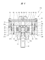
図4および図5に示されるように、カム収容室18がピストンケース14の径方向中央部に設けられている。カム部材19がカム収容室18内に組み込まれる。カム部材19は駆動軸16の先端部に固定され、駆動軸16により回転駆動される。4つのシリンダ孔21a〜21dがそれぞれカム収容室18に連通してピストンケース14に設けられており、シリンダ孔21a〜21dは内方端の部分でカム収容室18に連通している。シリンダ孔21a〜21dの中心軸は、駆動軸16およびカム部材19の回転中心軸Oに対して直交している。シリンダ孔21a〜21dはカム部材19に対して径方向に延びている。シリンダ孔21a〜21dは、図4に示されるように、円周方向に相互に90度ごとに設けられている。図4〜図6に示されるように、2つのシリンダ孔21a,21bはカム部材19の回転中心軸Oを中心に、一直線状つまり同軸に延びて対となっている。2つのシリンダ孔21c,21dはカム部材の回転中心軸Oを中心に、一直線状つまり同軸に延びて対となっている。このように、4つのシリンダ孔21a〜21dは、カム収容室18を中心として十字形状に配置されてピストンケース14に設けられている。   As shown in FIGS. 4 and 5, the cam housing chamber 18 is provided in the central portion in the radial direction of the piston case 14. A cam member 19 is incorporated in the cam housing chamber 18. The cam member 19 is fixed to the distal end portion of the drive shaft 16 and is driven to rotate by the drive shaft 16. Four cylinder holes 21a to 21d communicate with the cam housing chamber 18, respectively, and are provided in the piston case 14. The cylinder holes 21a to 21d communicate with the cam housing chamber 18 at the inner end portion. The center axes of the cylinder holes 21 a to 21 d are orthogonal to the drive shaft 16 and the rotation center axis O of the cam member 19. The cylinder holes 21 a to 21 d extend in the radial direction with respect to the cam member 19. As shown in FIG. 4, the cylinder holes 21 a to 21 d are provided every 90 degrees in the circumferential direction. As shown in FIGS. 4 to 6, the two cylinder holes 21 a and 21 b extend in a straight line, that is, coaxially with the rotation center axis O of the cam member 19 as a pair. The two cylinder holes 21c and 21d are paired extending in a straight line, that is, coaxially with the rotation center axis O of the cam member as the center. Thus, the four cylinder holes 21 a to 21 d are arranged in a cross shape with the cam housing chamber 18 as the center and are provided in the piston case 14.

それぞれのシリンダ孔21a〜21dの外方端は、それぞれ対応する装着面13a〜13dに開口している。図1および図4に示されるように、アダプタ22a〜22dがピストンケース14の装着面13a〜13dに、ねじ部材23により取り付けられている。アダプタ22a〜22dは、それぞれ装着面13a〜13dに取り付けられる磁石ホルダ24と、それぞれの磁石ホルダ24に取り付けられる流路プレート25とを有している。磁石ホルダ24と流路プレート25は、それぞれ樹脂やアルミニウム合金等の非磁性材料により形成される。   The outer ends of the respective cylinder holes 21a to 21d are opened to the corresponding mounting surfaces 13a to 13d, respectively. As shown in FIGS. 1 and 4, the adapters 22 a to 22 d are attached to the mounting surfaces 13 a to 13 d of the piston case 14 by screw members 23. Each of the adapters 22a to 22d has a magnet holder 24 attached to each of the mounting surfaces 13a to 13d and a flow path plate 25 attached to each magnet holder 24. The magnet holder 24 and the flow path plate 25 are each formed of a nonmagnetic material such as resin or aluminum alloy.

図4に示されるように、ピストン26a〜26dがそれぞれのシリンダ孔21a〜21dに往復動自在に装着される。ピストン26a〜26dは、樹脂やアルミニウム合金等の非磁性材料により形成される。ピストン26a〜26dの頂部はアダプタ22a〜22dに対向し、ピストン26a〜26dの底部はカム部材19に対向する。ポンプ室27a〜27dがピストン26a〜26dとアダプタ22a〜22dとにより区画される。ポンプ室27a〜27dは、ピストン26a〜26dがアダプタ22a〜22dに向けて移動すると収縮し、カム部材19に向けて移動すると膨張する。   As shown in FIG. 4, pistons 26a to 26d are attached to the respective cylinder holes 21a to 21d so as to reciprocate. The pistons 26a to 26d are formed of a nonmagnetic material such as a resin or an aluminum alloy. The top portions of the pistons 26 a to 26 d face the adapters 22 a to 22 d, and the bottom portions of the pistons 26 a to 26 d face the cam member 19. Pump chambers 27a to 27d are partitioned by pistons 26a to 26d and adapters 22a to 22d. The pump chambers 27a to 27d contract when the pistons 26a to 26d move toward the adapters 22a to 22d, and expand when the pistons 26a to 27d move toward the cam member 19.

永久磁石であるピストン磁石31がそれぞれのピストン26a〜26dの頂部に設けられている。ピストン磁石31は、外周面が円形となっており、中心がシリンダ孔21a〜21dの中心軸と同軸となって、ピストン26a〜26dの頂部に埋め込まれている。ピストン磁石31は、ピストン26a〜26dの頂面に露出しアダプタ22a〜22dに対向する対向面を有している。   A piston magnet 31, which is a permanent magnet, is provided at the top of each of the pistons 26a to 26d. The piston magnet 31 has a circular outer peripheral surface, the center is coaxial with the central axis of the cylinder holes 21a to 21d, and is embedded in the tops of the pistons 26a to 26d. The piston magnet 31 has a facing surface that is exposed on the top surfaces of the pistons 26a to 26d and faces the adapters 22a to 22d.

永久磁石からなるアダプタ磁石32が磁石ホルダ24に設けられている。アダプタ磁石32は、磁力発生部材を構成しており、磁石ホルダ24に埋め込まれ、磁石ホルダ24の内面に露出してピストン磁石31の露出面に対向する対向面を有している。   An adapter magnet 32 made of a permanent magnet is provided on the magnet holder 24. The adapter magnet 32 constitutes a magnetic force generating member, is embedded in the magnet holder 24, and has a facing surface that is exposed on the inner surface of the magnet holder 24 and faces the exposed surface of the piston magnet 31.

アダプタ磁石32の対向面は、ピストン磁石31の対向面と同極性となっている。これにより、アダプタ磁石32は、ピストン磁石31に対して反発する磁力を加え、ピストン26a〜26dにポンプ室27a〜27dを膨張させる方向の推力つまり膨張磁力を加える。   The facing surface of the adapter magnet 32 has the same polarity as the facing surface of the piston magnet 31. Thereby, the adapter magnet 32 applies a repulsive magnetic force to the piston magnet 31, and applies a thrust in the direction of expanding the pump chambers 27a to 27d to the pistons 26a to 26d, that is, an expanding magnetic force.

また、アダプタ磁石32の対向面は、ピストン磁石31の対向面と同極性となっているだけでなく、ピストン26aのピストン磁石31のカム部材19側の極性と、ピストン26bのピストン磁石31のカム部材19側の極性とは、異なっている。これにより、ピストン26aとピストン26bはお互いに引き合うので、ポンプ室27a,27bを膨張させる力を補助する。ピストン26cとピストン26dも同様である。   Further, the facing surface of the adapter magnet 32 is not only the same polarity as the facing surface of the piston magnet 31, but also the polarity of the piston magnet 31 of the piston 26a on the cam member 19 side and the cam of the piston magnet 31 of the piston 26b. The polarity on the member 19 side is different. Thereby, since the piston 26a and the piston 26b attract each other, the force which expands the pump chambers 27a and 27b is assisted. The same applies to the piston 26c and the piston 26d.

図4〜図6に示されるように、回転体33がそれぞれのピストン26a〜26dの底部に回転自在に装着される。回転体33を支持するための支持ピン34がピストン26a〜26dに取り付けられている。回転体33としては、ボール軸受が用いられており、支持ピン34に固定される内側回転体と、その外側に多数のボールを介して回転自在に装着される外側回転体とを有している。   As shown in FIGS. 4 to 6, the rotating body 33 is rotatably mounted on the bottom of each of the pistons 26 a to 26 d. A support pin 34 for supporting the rotating body 33 is attached to the pistons 26a to 26d. As the rotator 33, a ball bearing is used. The rotator 33 includes an inner rotator fixed to the support pin 34 and an outer rotator that is rotatably mounted on the outside via a large number of balls. .

カム面35がカム部材19に設けられており、カム面35は、回転体33の外周面つまり外側回転体の外周面に転がり接触する。カム部材19は、図4に示されるように、最大半径の長径部と最小半径の短径部とを有している。カム面35は、回転体33の外径に合わせて設計されており、ピストン26a,26b,26c,26dの移動軌跡はsin曲線となるようなカム面である。カム部材19が電動モータ12により回転駆動されると、ピストン26a〜26dは、アダプタ22a〜22dに最も近づく位置から最も遠ざかる位置との間を往復動する。   A cam surface 35 is provided on the cam member 19, and the cam surface 35 is in rolling contact with the outer peripheral surface of the rotating body 33, that is, the outer peripheral surface of the outer rotating body. As shown in FIG. 4, the cam member 19 has a long diameter portion with a maximum radius and a short diameter portion with a minimum radius. The cam surface 35 is designed in accordance with the outer diameter of the rotating body 33, and the movement trajectory of the pistons 26a, 26b, 26c, and 26d is a cam surface that forms a sin curve. When the cam member 19 is rotationally driven by the electric motor 12, the pistons 26a to 26d reciprocate between a position closest to the adapters 22a to 22d and a position farthest from the position closest to the adapter 22a to 22d.

図4に示されるように、カム面35の長径部が回転体33と転がり接触すると、対をなす2つのピストン26c,26dは、アダプタ22c,22dに最も近づく。この最も近づく位置に向けてピストンが移動するときには、ピストン磁石31とアダプタ磁石32との反発力に抗して2つのピストン26c,26dがアダプタ22c,22dに向けて移動し、ポンプ室27c,27dが収縮される。   As shown in FIG. 4, when the long diameter portion of the cam surface 35 is in rolling contact with the rotating body 33, the two pistons 26c and 26d that make a pair are closest to the adapters 22c and 22d. When the piston moves toward the closest position, the two pistons 26c and 26d move toward the adapters 22c and 22d against the repulsive force between the piston magnet 31 and the adapter magnet 32, and the pump chambers 27c and 27d. Is shrunk.

カム面35の長径部が回転体33と転がり接触したときには、図4に示されるように、カム面35の短径部は回転体33と転がり接触する。このときには、対をなす2つのピストン26a,26bは、アダプタ22a,22bから最も遠ざかる。カム面35の長径部が回転体に接触した位置から短径部が接触する位置に向けてカム部材19が回転するときには、ピストン磁石31とアダプタ磁石32との反発力により、ピストンはアダプタに対して最も近づく位置から最も遠ざかる位置に移動する。これにより、ポンプ室が膨張する。図4は、回転体33がカム面35の短径部に接触し、ポンプ室27a,27bが最も膨張した状態を示す。   When the long diameter portion of the cam surface 35 comes into rolling contact with the rotating body 33, the short diameter portion of the cam surface 35 comes into rolling contact with the rotating body 33 as shown in FIG. 4. At this time, the two pistons 26a and 26b making a pair are furthest away from the adapters 22a and 22b. When the cam member 19 rotates from the position where the long diameter portion of the cam surface 35 is in contact with the rotating body to the position where the short diameter portion is in contact, the repulsive force between the piston magnet 31 and the adapter magnet 32 causes the piston to move against the adapter. Move to the position farthest from the closest position. As a result, the pump chamber expands. FIG. 4 shows a state where the rotating body 33 is in contact with the short diameter portion of the cam surface 35 and the pump chambers 27a and 27b are expanded most.

このように、アダプタ磁石32がそれぞれのピストン26a〜26dにポンプ室27a〜27dを膨張させる方向の磁力を加えた状態のもとで、カム部材19のカム面35と回転体33との転がり接触により、ピストン26a〜26dは直線往復動している。つまり、カム部材19とピストン26a〜26dは滑り接触つまり摺動接触することがない。これにより、カム面35の摩耗発生が防止されて、カム部材19を高速回転させても、コンプレッサ10aの高い耐久性を維持できる。   In this way, the rolling contact between the cam surface 35 of the cam member 19 and the rotating body 33 is performed in a state where the adapter magnet 32 applies a magnetic force in the direction of expanding the pump chambers 27a to 27d to the pistons 26a to 26d. Thus, the pistons 26a to 26d are reciprocating linearly. That is, the cam member 19 and the pistons 26a to 26d do not make sliding contact, that is, sliding contact. Thereby, the wear of the cam surface 35 is prevented, and the high durability of the compressor 10a can be maintained even when the cam member 19 is rotated at a high speed.

さらに、同軸に延びて2つで対をなすシリンダ孔にピストンが設けられている。対をなすピストンは同時に外側に向けて、または2つ同時に内側に向けて動くので、2つのピストンの重心は偏心することなく一定位置を保つ。従って、ピストンの動的バランスが高められ、高速動作させることが可能となる。特に、図4に示されるように、2対のシリンダ孔をピストンケース14に設け、一対のシリンダ孔21c,21dに設けられたピストン26c,26dによりポンプ室27c,27dが膨張するときに、他の一対のシリンダ孔21a,21bに設けられたピストン26a,26bによりポンプ室27a,27bを収縮させると、コンプレッサの動的バランスが高められ、高速動作させることが可能となる。   Furthermore, the piston is provided in the cylinder hole which extends coaxially and makes a pair of two. Since the paired pistons move outward simultaneously or two simultaneously inward, the center of gravity of the two pistons remains constant without being eccentric. Therefore, the dynamic balance of the piston is increased and it is possible to operate at high speed. In particular, as shown in FIG. 4, when two pairs of cylinder holes are provided in the piston case 14 and the pump chambers 27c and 27d are expanded by the pistons 26c and 26d provided in the pair of cylinder holes 21c and 21d, When the pump chambers 27a and 27b are contracted by the pistons 26a and 26b provided in the pair of cylinder holes 21a and 21b, the dynamic balance of the compressor is enhanced and the pump chamber 27a and 27b can be operated at high speed.

全てのシリンダ孔21a〜21dの中心軸は1点で交差しているので、1つのカム部材19によって全てのピストン26a〜26dを駆動することができる。したがって、ピストンケース14の駆動軸方向寸法を小さくすることができる。このように、小型のピストンケース14により所望のポンプ室容積を得ることができるので、コンプレッサを小型化することができる。   Since the central axes of all the cylinder holes 21 a to 21 d intersect at one point, all the pistons 26 a to 26 d can be driven by one cam member 19. Therefore, the dimension of the piston case 14 in the drive shaft direction can be reduced. Thus, since a desired pump chamber volume can be obtained by the small piston case 14, the compressor can be miniaturized.

図1に示されるように、吸気口41がそれぞれの流路プレート25に設けられている。図8および図9(B)に示されるように、吸気連通孔42が吸気口41に対応させて磁石ホルダ24に設けられている。図9(A)に示されるように、吸気弁43が磁石ホルダ24の内面にねじ部材44により取り付けられている。吸気弁43は、逆止弁の機能を有しており、ポンプ室が膨張すると、吸気連通孔42を開いて吸気口41から空気をポンプ室に導入し、ポンプ室が収縮すると、吸気連通孔42を閉じてポンプ室から吸気口41に空気が流れるのを阻止する。   As shown in FIG. 1, intake ports 41 are provided in the respective flow path plates 25. As shown in FIGS. 8 and 9B, the intake communication hole 42 is provided in the magnet holder 24 so as to correspond to the intake port 41. As shown in FIG. 9A, the intake valve 43 is attached to the inner surface of the magnet holder 24 with a screw member 44. The intake valve 43 functions as a check valve. When the pump chamber is expanded, the intake communication hole 42 is opened to introduce air into the pump chamber from the intake port 41. When the pump chamber is contracted, the intake communication hole 42 is closed to prevent air from flowing from the pump chamber to the intake port 41.

図8に示されるように、吐出口45が磁石ホルダ24に設けられ、吐出口45は流路プレート25の内面に形成された連通凹部46に連通している。図9(B)に示されるように、吐出弁47が磁石ホルダ24の外面にねじ部材48により取り付けられている。吐出弁47は、逆止弁の機能を有しており、ポンプ室が膨張すると、吐出口45を閉じて吐出口45から空気がポンプ室内に逆流するのを阻止し、ポンプ室が収縮すると、吐出口45を開いて吐出口45から連通凹部46内に空気を吐出する。   As shown in FIG. 8, the discharge port 45 is provided in the magnet holder 24, and the discharge port 45 communicates with a communication recess 46 formed on the inner surface of the flow path plate 25. As shown in FIG. 9B, the discharge valve 47 is attached to the outer surface of the magnet holder 24 by a screw member 48. The discharge valve 47 has a check valve function. When the pump chamber is expanded, the discharge port 45 is closed to prevent the air from flowing back from the discharge port 45 into the pump chamber, and when the pump chamber is contracted, The discharge port 45 is opened and air is discharged from the discharge port 45 into the communication recess 46.

図9に示されるように、磁石ホルダ24はねじ部材49によりピストンケース14に固定される。流路プレート25は図1に示されるねじ部材23によりピストンケース14に固定され、ねじ部材23は磁石ホルダ24に設けられた取付孔23aを貫通する。図9には、磁石ホルダ24と流路プレート25とが1つずつ示されているが、全ての磁石ホルダ24と流路プレート25が同様の構造となっている。   As shown in FIG. 9, the magnet holder 24 is fixed to the piston case 14 by a screw member 49. The flow path plate 25 is fixed to the piston case 14 by a screw member 23 shown in FIG. 1, and the screw member 23 passes through an attachment hole 23 a provided in the magnet holder 24. Although one magnet holder 24 and one flow path plate 25 are shown in FIG. 9, all the magnet holders 24 and the flow path plates 25 have the same structure.

図6および図7に示されるように、連通流路51が流路プレート25に設けられている。連通流路51は一端が連通凹部46に連通し、他端が流路プレート25の端面に開口している。図1に示されるように、十字形状の吐出プレート52が流路プレート25にねじ部材53により固定される。吐出プレート52はピストンケース14の端面に密着している。図6および図7に示されるように、連通開口部54が吐出プレート52の中央部に設けられており、連通開口部54は連通流路55により連通流路51に連通している。ジョイント部材56が吐出プレート52の中央部にねじ部材57により固定されており、連通開口部54に連通する吐出口58がジョイント部材56に設けられている。したがって、圧縮空気はポンプ室27a〜27dから加圧されて吐出され、吐出口58に集合されて外部に吐出される。吐出口58から吐出された圧縮空気を外部の機器に案内するときには、吐出口58には配管等が接続される。   As shown in FIGS. 6 and 7, the communication channel 51 is provided in the channel plate 25. One end of the communication channel 51 communicates with the communication recess 46, and the other end opens on the end surface of the channel plate 25. As shown in FIG. 1, the cross-shaped discharge plate 52 is fixed to the flow path plate 25 by a screw member 53. The discharge plate 52 is in close contact with the end surface of the piston case 14. As shown in FIG. 6 and FIG. 7, the communication opening 54 is provided at the center of the discharge plate 52, and the communication opening 54 communicates with the communication channel 51 through the communication channel 55. A joint member 56 is fixed to the central portion of the discharge plate 52 by a screw member 57, and a discharge port 58 communicating with the communication opening 54 is provided in the joint member 56. Accordingly, the compressed air is pressurized and discharged from the pump chambers 27a to 27d, is collected at the discharge port 58, and is discharged to the outside. When the compressed air discharged from the discharge port 58 is guided to an external device, piping or the like is connected to the discharge port 58.

図10は他の実施の形態であるピストン式コンプレッサ10bの外観を示す斜視図である。このコンプレッサ10bは、上述した4つのシリンダ孔21a〜21dを1組として、2組のシリンダ孔がピストンケース14に設けられている。つまり、対をなす2つのシリンダ孔21a,21bと、他の対をなす2つのシリンダ孔21c,21dが合計4対設けられている。それぞれのシリンダ孔には、ピストン26a〜26dが収容されている。合計4つの磁石ホルダ24がそれぞれのピストン26a〜26dに対応してピストンケース14に設けられている。このように、ピストンケース14に複数組のシリンダ孔を設けるようにしても良い。   FIG. 10 is a perspective view showing an appearance of a piston type compressor 10b according to another embodiment. The compressor 10b includes the above-described four cylinder holes 21a to 21d as one set, and two sets of cylinder holes are provided in the piston case 14. That is, a total of four pairs of two cylinder holes 21a and 21b making a pair and two cylinder holes 21c and 21d making another pair are provided. Pistons 26a to 26d are accommodated in the respective cylinder holes. A total of four magnet holders 24 are provided in the piston case 14 corresponding to the respective pistons 26a to 26d. As described above, a plurality of sets of cylinder holes may be provided in the piston case 14.

図11は他の実施の形態であるピストン式コンプレッサ10cを示す断面図であり、図12は図11の斜視図である。図11は上述したコンプレッサ10aにおける図6と同様の部分の断面を示す。   FIG. 11 is a cross-sectional view showing a piston type compressor 10c according to another embodiment, and FIG. 12 is a perspective view of FIG. FIG. 11 shows a cross section of the same portion as FIG. 6 in the above-described compressor 10a.

図11および図12に示されるコンプレッサ10cは、上述したコンプレッサ10aと同様に、4つのピストン26a〜26dを有しており、ピストンケース14とアダプタ22a〜22dの構造は、上述したコンプレッサ10aと同様である。これに対し、図11および図12のコンプレッサ10cは、ピストン26a〜26dとカム部材19の構造が上述したコンプレッサ10aと相違している。   The compressor 10c shown in FIG. 11 and FIG. 12 has four pistons 26a to 26d similarly to the compressor 10a described above, and the structures of the piston case 14 and the adapters 22a to 22d are the same as those of the compressor 10a described above. It is. On the other hand, the compressor 10c of FIGS. 11 and 12 is different from the compressor 10a described above in the structure of the pistons 26a to 26d and the cam member 19.

ピストン磁石31は、ピストン26a〜26dの底部に設けられており、ピストン磁石31の露出面はカム部材19に対向している。アダプタ22a〜22dには、コンプレッサ10aと同様に、アダプタ磁石32が磁力発生部材として設けられている。ピストン磁石31の露出面に対して反対側の面は、アダプタ磁石32の対向面と同極性となっている。これにより、アダプタ磁石32は、ピストン磁石31に対して反発する磁力を加えることにより、ポンプ室27a〜27dを膨張する方向の推力つまり膨張磁力をピストン26a〜26dに加える。図11および図12においては、アダプタ22a,22bが示されているが、他のアダプタ22c,22dも同様の構造となっている。   The piston magnet 31 is provided at the bottom of the pistons 26 a to 26 d, and the exposed surface of the piston magnet 31 faces the cam member 19. Similarly to the compressor 10a, the adapter magnet 32 is provided in the adapters 22a to 22d as a magnetic force generating member. The surface opposite to the exposed surface of the piston magnet 31 has the same polarity as the facing surface of the adapter magnet 32. As a result, the adapter magnet 32 applies a repulsive magnetic force to the piston magnet 31, thereby applying a thrust in the direction of expanding the pump chambers 27a to 27d, that is, an expanding magnetic force to the pistons 26a to 26d. 11 and 12, adapters 22a and 22b are shown, but the other adapters 22c and 22d have the same structure.

カム磁石36がカム部材19に設けられている。カム磁石36のピストン磁石31に対向する面の極性は、ピストン磁石31の露出面の極性と同極性となっている。これにより、カム磁石36は、ピストン磁石31に反発する磁力を加えることにより、ポンプ室27a〜27dを収縮する方向の推力つまり収縮磁力をピストン26a〜26dに加える。   A cam magnet 36 is provided on the cam member 19. The polarity of the surface of the cam magnet 36 facing the piston magnet 31 is the same as the polarity of the exposed surface of the piston magnet 31. Thereby, the cam magnet 36 applies a thrust force in the direction of contracting the pump chambers 27a to 27d, that is, a contracting magnetic force to the pistons 26a to 26d by applying a repulsive magnetic force to the piston magnet 31.

カム磁石36は、カム部材19の回転中心からの半径方向に長い長さを持つ、長寸の磁石片と、長寸の磁石片よりも半径方向の長さが短い、短寸の磁石片とを有している。長寸の磁石片と短寸の磁石片は、回転方向に90度ずれて2つずつ設けられる。2つの長寸の磁石片は、回転中心軸を中心として対称位置に位置する。2つの短寸の磁石片は、回転中心軸を中心として対称位置に位置する。図11および図12には、カム磁石36の短寸の磁石片がピストン磁石31に対向した状態が示されている。ピストン磁石31はピストン26a〜26dの底部に設けられており、カム磁石36はピストン磁石31に直接対向し、アダプタ磁石32はピストン26a〜26dを介して対向しているので、カム磁石36によるポンプ室27a〜27dの収縮方向の推力は、アダプタ磁石32によるポンプ室27a〜27dの膨張方向の推力よりも大きくなっている。   The cam magnet 36 includes a long magnet piece having a long length in the radial direction from the rotation center of the cam member 19, and a short magnet piece having a shorter radial length than the long magnet piece. have. Two long magnet pieces and two short magnet pieces are provided with a 90 degree shift in the rotational direction. The two long magnet pieces are located at symmetrical positions around the rotation center axis. The two short magnet pieces are located at symmetrical positions around the rotation center axis. 11 and 12 show a state in which the short magnet piece of the cam magnet 36 faces the piston magnet 31. The piston magnet 31 is provided at the bottom of the pistons 26a to 26d, the cam magnet 36 directly faces the piston magnet 31, and the adapter magnet 32 faces the pistons 26a to 26d. The thrust in the contraction direction of the chambers 27a to 27d is larger than the thrust in the expansion direction of the pump chambers 27a to 27d by the adapter magnet 32.

したがって、駆動軸16の回転に伴って長寸の磁石片がピストン磁石31に対向する位置に接近すると、ピストン磁石31とカム磁石36の反発力により、ピストン26a〜26dは、ピストン磁石31とアダプタ磁石32の反発力に抗してアダプタ22a〜22dに向けて駆動される。これにより、ポンプ室27a〜27dは収縮する。一方、長寸の磁石片がピストン磁石31に対向する位置から離れると、ピストン磁石31とアダプタ磁石32の反発力がピストン磁石31とカム磁石36の反発力よりも勝り、ピストン26a〜26dはアダプタ22a〜22dから離れる方向に駆動される。これにより、ポンプ室27a〜27dは膨張する。棒状のストッパ37がピストンケース14に取り付けられており、ストッパ37はピストン26a〜26dに当接し、ピストン26a〜26dがカム磁石36に最接近する位置を規制する。これにより、ピストン26a〜26dはカム磁石36に当接しない。   Therefore, when the long magnet piece approaches the position facing the piston magnet 31 as the drive shaft 16 rotates, the pistons 26a to 26d are caused to react with the piston magnet 31 and the adapter by the repulsive force of the piston magnet 31 and the cam magnet 36. It is driven toward the adapters 22a to 22d against the repulsive force of the magnet 32. Thereby, the pump chambers 27a to 27d contract. On the other hand, when the long magnet piece is separated from the position facing the piston magnet 31, the repulsive force of the piston magnet 31 and the adapter magnet 32 is greater than the repulsive force of the piston magnet 31 and the cam magnet 36, and the pistons 26a to 26d are adapters. It is driven in a direction away from 22a to 22d. Thereby, the pump chambers 27a to 27d expand. A rod-shaped stopper 37 is attached to the piston case 14, and the stopper 37 abuts against the pistons 26 a to 26 d, and regulates the position where the pistons 26 a to 26 d are closest to the cam magnet 36. Thereby, the pistons 26 a to 26 d do not contact the cam magnet 36.

このように、本実施例では、ピストン磁石31と、アダプタ磁石32と、カム磁石36との反発力を利用する。カム部材19の回転によって、カム磁石36によりピストン磁石31に加わる反発力を変化させ、ピストン26a〜26dが往復動される。このように、カム部材19の回転により、非接触でピストン26a〜26dを駆動するようにしたので、カム部材19が摩耗することはない。これにより、カム部材19を高速回転させても、コンプレッサ10cの高い耐久性を維持できる。さらに、上述したコンプレッサ10aと同様に、コンプレッサ10cの小型化を達成することができる。   Thus, in this embodiment, the repulsive force of the piston magnet 31, the adapter magnet 32, and the cam magnet 36 is used. The repulsive force applied to the piston magnet 31 by the cam magnet 36 is changed by the rotation of the cam member 19, and the pistons 26a to 26d are reciprocated. As described above, since the pistons 26a to 26d are driven in a non-contact manner by the rotation of the cam member 19, the cam member 19 is not worn. Thereby, even if the cam member 19 is rotated at high speed, the high durability of the compressor 10c can be maintained. Furthermore, similarly to the compressor 10a described above, the compressor 10c can be reduced in size.

図13は、さらに他の実施の形態であるピストン式コンプレッサ10dの外観を示す斜視図である。図14は図13に示されたコンプレッサ組立体を示す断面図であり、図15は図14の斜視図である。   FIG. 13 is a perspective view showing the appearance of a piston-type compressor 10d as still another embodiment. 14 is a cross-sectional view showing the compressor assembly shown in FIG. 13, and FIG. 15 is a perspective view of FIG.

このコンプレッサ10dは、上述したコンプレッサ10a,10cと同様に、4つのシリンダ孔21a〜21dが設けられたピストンケース14を有している。カム磁石36が、コンプレッサ10cと同様に、カム部材19に設けられている。これに対し、第1のピストン磁石31aがピストン26a〜26dの頂部に設けられ、第2のピストン磁石31bがピストン26a〜26dの底部に設けられている。第1のピストン磁石31aはピストン26a〜26dの頂面に露出してアダプタ22a〜22dに対向する対向面を有している。第2のピストン磁石31bはピストン26a〜26dの底面に露出してカム磁石36に対向する対向面を有している。図14および図15には、ピストン26a,26bが示されているが、他のピストン26c,26dも同様に、第1のピストン磁石31cと第2のピストン磁石31dが設けられている。   The compressor 10d has a piston case 14 provided with four cylinder holes 21a to 21d, similarly to the compressors 10a and 10c described above. The cam magnet 36 is provided on the cam member 19 in the same manner as the compressor 10c. On the other hand, the 1st piston magnet 31a is provided in the top part of piston 26a-26d, and the 2nd piston magnet 31b is provided in the bottom part of piston 26a-26d. The first piston magnet 31a has a facing surface that is exposed on the top surfaces of the pistons 26a to 26d and faces the adapters 22a to 22d. The second piston magnet 31b has a facing surface exposed to the bottom surfaces of the pistons 26a to 26d and facing the cam magnet 36. 14 and 15 show the pistons 26a and 26b, the other pistons 26c and 26d are similarly provided with a first piston magnet 31c and a second piston magnet 31d.

アダプタ22a〜22dがピストンケース14の装着面13a〜13dに装着され、ソレノイド61がそれぞれのアダプタ22a〜22dに設けられている。ソレノイド61は磁力発生部材を構成しており、アダプタ22a〜22dはソレノイドホルダを構成している。ソレノイド61は鉄心62が組み込まれたボビン63を有し、ボビン63の外側にはコイル64が巻き付けられている。図13に示されるように、コイル64の接続端子65がアダプタ22a〜22dの外部に突出しており、接続端子65に接続される図示しない給電プラグを介して、コイル64には外部から電力が供給される。   Adapters 22a to 22d are mounted on the mounting surfaces 13a to 13d of the piston case 14, and solenoids 61 are provided in the respective adapters 22a to 22d. The solenoid 61 constitutes a magnetic force generating member, and the adapters 22a to 22d constitute a solenoid holder. The solenoid 61 has a bobbin 63 in which an iron core 62 is incorporated, and a coil 64 is wound around the bobbin 63. As shown in FIG. 13, the connection terminal 65 of the coil 64 protrudes outside the adapters 22 a to 22 d, and power is supplied to the coil 64 from the outside via a power supply plug (not shown) connected to the connection terminal 65. Is done.

このコンプレッサ10dにおいては、コイル64に供給される電力により第1のピストン磁石31aに対して反発する磁力がソレノイド61により加えられる。これにより、ポンプ室27a〜27dを膨張する方向の推力つまり膨張磁力がピストン26a〜26dに加えられる。   In the compressor 10d, a magnetic force repelling the first piston magnet 31a by the electric power supplied to the coil 64 is applied by the solenoid 61. Thereby, thrust in the direction of expanding the pump chambers 27a to 27d, that is, expansion magnetic force is applied to the pistons 26a to 26d.

一方、カム磁石36は、コンプレッサ10cのカム磁石36と同様に、第2のピストン磁石31bに反発する磁力を加える。これにより、ポンプ室27a〜27dを収縮する方向の推力つまり収縮磁力がピストン26a〜26dに加えられる。   On the other hand, the cam magnet 36 applies a repulsive magnetic force to the second piston magnet 31b, like the cam magnet 36 of the compressor 10c. Thereby, thrust in the direction of contracting the pump chambers 27a to 27d, that is, contracting magnetic force is applied to the pistons 26a to 26d.

コンプレッサ10dにおいては、コイル64に対する電力量や通電タイミングを制御することにより、ソレノイド61により第1のピストン磁石31aに加えられる反発力の強度と、磁力を発生させるタイミングとをカム部材19の回転位置に応じて変化させることができる。   In the compressor 10d, the amount of power to the coil 64 and the energization timing are controlled, whereby the strength of the repulsive force applied to the first piston magnet 31a by the solenoid 61 and the timing for generating the magnetic force are determined by the rotational position of the cam member 19. It can be changed according to.

このように、コンプレッサ10dにおいては、第1のピストン磁石31aおよびソレノイド61の反発力と、第2のピストン磁石31bおよびカム磁石36の反発力とを利用する。つまり、第2のピストン磁石31bにカム磁石36から加えられる反発力をカム磁石36の回転に応じて変化させることにより、ピストン26a〜26dが往復動される。したがって、コンプレッサ10dにおいても、カム部材19の回転により、非接触でピストン26a〜26dを駆動するようにしたので、カム部材19が摩耗することはない。これにより、カム部材19を高速回転させても、コンプレッサ10cの高い耐久性を維持できる。さらに、上述したコンプレッサ10a〜10cと同様に、コンプレッサ10dの小型化を達成することができる。   Thus, in the compressor 10d, the repulsive force of the first piston magnet 31a and the solenoid 61 and the repulsive force of the second piston magnet 31b and the cam magnet 36 are used. That is, by changing the repulsive force applied to the second piston magnet 31b from the cam magnet 36 according to the rotation of the cam magnet 36, the pistons 26a to 26d are reciprocated. Therefore, in the compressor 10d as well, since the pistons 26a to 26d are driven in a non-contact manner by the rotation of the cam member 19, the cam member 19 is not worn. Thereby, even if the cam member 19 is rotated at high speed, the high durability of the compressor 10c can be maintained. Furthermore, similarly to the compressors 10a to 10c described above, the compressor 10d can be reduced in size.

それぞれのコンプレッサ10a〜10dにおいては、カム部材19の回転によりピストンを駆動させるようにしたので、駆動軸とピストンとをコンロッドを介して連結する場合に比して、コンプレッサの小型化を達成することができる。また、カム部材19とピストンとが摺動接触しないので、摺動に起因した摩耗発生がなく、高速で駆動してもコンプレッサの高い耐久性を維持できる。さらに、同軸に延びて2つで対をなすシリンダ孔にピストンが設けられている。対をなすピストンは同時に外側に向けて、または2つ同時に内側に向けて動くので、2つのピストンの重心は偏心することなく一定位置を保つ。従って、コンプレッサの動的バランスが得られ、高速動作させることが可能となる。   In each of the compressors 10a to 10d, since the piston is driven by the rotation of the cam member 19, the size of the compressor can be reduced as compared with the case where the drive shaft and the piston are connected via a connecting rod. Can do. Further, since the cam member 19 and the piston are not in sliding contact with each other, there is no occurrence of wear due to sliding, and high durability of the compressor can be maintained even when driven at a high speed. Furthermore, the piston is provided in the cylinder hole which extends coaxially and makes a pair of two. Since the paired pistons move outward simultaneously or two simultaneously inward, the center of gravity of the two pistons remains constant without being eccentric. Therefore, a dynamic balance of the compressor can be obtained, and high speed operation can be achieved.

本発明は前記実施の形態に限定されるものではなく、その要旨を逸脱しない範囲で種々変更可能である。たとえば、それぞれのコンプレッサ10a,10c,10dにおいては、4つのシリンダ孔21a〜21dの中心軸が回転中心軸Oに直交してピストンケース14に設けられているが、1組を構成するシリンダ孔の数は、4つに限られることなく、任意の数のシリンダ孔をピストンケース14に設けることができる。ピストンケース14に複数のシリンダ孔を設ける場合には、ピストンケース14に相互に円周方向にずらしてシリンダ孔を設け、それぞれのシリンダ孔にピストンが装着される。また、コンプレッサ10a,10cにおけるアダプタ磁石32に代えて、コンプレッサ10dに示されるソレノイド61を用いるようにしても良く、ピストンに対する永久磁石の組み付け形態と、アダプタに対して設けられる磁力発生部材の形態は、種々の組み合わせとすることができる。コンプレッサにより圧縮する気体としては、空気のみに限られず、種々の気体を加圧することができる。   The present invention is not limited to the above-described embodiment, and various modifications can be made without departing from the scope of the invention. For example, in each of the compressors 10a, 10c, and 10d, the center axes of the four cylinder holes 21a to 21d are provided in the piston case 14 so as to be orthogonal to the rotation center axis O. The number is not limited to four, and an arbitrary number of cylinder holes can be provided in the piston case 14. When a plurality of cylinder holes are provided in the piston case 14, the cylinder holes are provided in the piston case 14 so as to be shifted from each other in the circumferential direction, and a piston is attached to each cylinder hole. Moreover, it may replace with the adapter magnet 32 in compressor 10a, 10c, and you may make it use the solenoid 61 shown by the compressor 10d, and the form of the assembly of the permanent magnet with respect to a piston and the form of the magnetic force generation member provided with respect to an adapter are as follows. Various combinations can be made. The gas compressed by the compressor is not limited to air, and various gases can be pressurized.

ピストン式コンプレッサ10c、10dにおいて、長寸の磁石片と短寸の磁石片を設けたが、短寸の磁石片は無くても良い。さらには、長寸の磁石片と短寸の磁石片はその極性が反対になるように設けてもよい。この場合には、長寸の磁石片がポンプ室26a、26bを圧縮し、続いて駆動軸16が90度回転したときには短寸の磁石片がポンプ室26a、26bを膨張させる力をピストン26a、26bに与える。また、この場合には短寸の磁石片の長さは、長寸の磁石片と同じであっても良い。   In the piston compressors 10c and 10d, the long magnet piece and the short magnet piece are provided, but the short magnet piece may be omitted. Furthermore, you may provide a long magnet piece and a short magnet piece so that the polarity may become reverse. In this case, the long magnet piece compresses the pump chambers 26a and 26b, and when the drive shaft 16 is subsequently rotated 90 degrees, the short magnet piece exerts a force to expand the pump chambers 26a and 26b. 26b. In this case, the length of the short magnet piece may be the same as that of the long magnet piece.

10a〜10d ピストン式コンプレッサ
11 コンプレッサ組立体
12 電動モータ
13a〜13d 装着面
14 ピストンケース
16 駆動軸
18 カム収容室
19 カム部材
21a〜21d シリンダ孔
22a〜22d アダプタ
24 磁石ホルダ
25 流路プレート
26a〜26d ピストン
27a〜27d ポンプ室
31 ピストン磁石
31a 第1のピストン磁石
31b 第2のピストン磁石
32 アダプタ磁石
33 回転体
35 カム面
36 カム磁石
43 吸気弁
47 吐出弁
52 吐出プレート
61 ソレノイド
64 コイル
10a to 10d Piston compressor 11 Compressor assembly 12 Electric motors 13a to 13d Mounting surface 14 Piston case 16 Drive shaft 18 Cam accommodating chamber 19 Cam members 21a to 21d Cylinder holes 22a to 22d Adapter 24 Magnet holder 25 Flow path plates 26a to 26d Pistons 27a to 27d Pump chamber 31 Piston magnet 31a First piston magnet 31b Second piston magnet 32 Adapter magnet 33 Rotating body 35 Cam surface 36 Cam magnet 43 Intake valve 47 Discharge valve 52 Discharge plate 61 Solenoid 64 Coil

Claims (7)

カム部材が組み込まれるカム収容室、および前記カム部材の回転中心軸に直交する軸上に、それぞれ前記回転中心軸に対して対称位置に位置して2つで対をなすシリンダ孔が前記回転中心軸を中心に90度ずらして2対設けられたピストンケースと、
前記ピストンケースに回転自在に装着され、前記カム部材を回転駆動する駆動軸と、
それぞれの前記シリンダ孔に往復動自在に収容されるピストンと、
前記ピストンケースに取り付けられ、前記ピストンとの間でポンプ室を区画するアダプタと、
それぞれの前記ピストンに設けられるピストン磁石と、
それぞれの前記アダプタに設けられ、前記ピストン磁石に反発する磁力を加えることにより前記ピストンに前記ポンプ室が膨張する方向の推力を加える磁力発生部材と、を有し、
一対の前記シリンダ孔に設けられた一対の前記ピストンにより一対の前記ポンプ室が膨張するときに、他の一対の前記シリンダ孔に設けられた他の一対の前記ピストンにより他の一対の前記ポンプ室を収縮する、ピストン式コンプレッサ。
Cam housing chamber in which the cam member is incorporated, and on an axis perpendicular to the axis of rotation of the cam member, the cylinder bore is the center of rotation form a 2 Tsude pairs located at symmetrical positions with respect to each of the rotation center shaft and 2 oppositely arranged kicked the piston case shifted 90 degrees about the axis,
A drive shaft that is rotatably mounted on the piston case and rotationally drives the cam member;
Pistons reciprocally accommodated in the respective cylinder holes;
An adapter attached to the piston case and defining a pump chamber with the piston;
A piston magnet provided on each of the pistons;
Provided in each of said adapter, it has a, a magnetic force generating member for applying a thrust in the direction of the pump chamber expands to the piston by applying a magnetic force to repel the piston magnet,
When the pair of pump chambers is expanded by the pair of pistons provided in the pair of cylinder holes, the other pair of pump chambers is provided by the other pair of pistons provided in the other pair of cylinder holes. The piston type compressor that contracts .
請求項1記載のピストン式コンプレッサにおいて、
前記ピストンに回転体を設け、
前記回転体の外周面に転がり接触して前記ピストンに前記ポンプ室が収縮する方向の推力を加えるカム面を前記カム部材に形成した、ピストン式コンプレッサ。
The piston type compressor according to claim 1, wherein
A rotating body is provided on the piston,
A piston-type compressor, wherein a cam surface is formed on the cam member that rolls into contact with the outer peripheral surface of the rotating body and applies a thrust force in a direction in which the pump chamber contracts to the piston.
請求項1記載のピストン式コンプレッサにおいて、
前記ピストン磁石に反発する磁力を加えて前記ピストンに対して前記ポンプ室が収縮する方向の推力を加えるカム磁石を前記カム部材に設けた、ピストン式コンプレッサ。
The piston type compressor according to claim 1, wherein
A piston-type compressor, wherein a cam magnet is provided on the cam member to apply a magnetic force repelling the piston magnet to apply a thrust force in a direction in which the pump chamber contracts against the piston.
請求項1〜3のいずれか1項に記載のピストン式コンプレッサにおいて、前記磁力発生部材は、アダプタ磁石である、ピストン式コンプレッサ。   The piston type compressor according to any one of claims 1 to 3, wherein the magnetic force generating member is an adapter magnet. 請求項1〜3のいずれか1項に記載のピストン式コンプレッサにおいて、前記磁力発生部材は、ソレノイドである、ピストン式コンプレッサ。   The piston type compressor according to any one of claims 1 to 3, wherein the magnetic force generating member is a solenoid. 請求項3記載のピストン式コンプレッサにおいて、前記磁力発生部材はアダプタ磁石であり、前記ピストン磁石を前記カム部材に対向させて前記ピストンの底部に設け、前記カム磁石による前記ポンプ室の収縮方向の推力を、前記アダプタ磁石による前記ポンプ室の膨張方向の推力よりも大きくした、ピストン式コンプレッサ。   4. The piston compressor according to claim 3, wherein the magnetic force generating member is an adapter magnet, the piston magnet is provided at the bottom of the piston so as to face the cam member, and the thrust in the contraction direction of the pump chamber by the cam magnet. Is a piston type compressor, which is larger than the thrust in the expansion direction of the pump chamber by the adapter magnet. 請求項3記載のピストン式コンプレッサにおいて、前記磁力発生部材は、ソレノイドであり、前記ソレノイドに対向させて前記ピストンの頂部に第1のピストン磁石を設け、前記カム磁石に対向させて前記ピストンの底部に第2のピストン磁石を設けた、ピストン式コンプレッサ。   4. The piston-type compressor according to claim 3, wherein the magnetic force generating member is a solenoid, a first piston magnet is provided on the top of the piston so as to face the solenoid, and a bottom of the piston is made facing the cam magnet. A piston type compressor provided with a second piston magnet.
JP2014146421A 2014-07-17 2014-07-17 Piston compressor Active JP6210943B2 (en)

Priority Applications (1)

Application Number Priority Date Filing Date Title
JP2014146421A JP6210943B2 (en) 2014-07-17 2014-07-17 Piston compressor

Applications Claiming Priority (1)

Application Number Priority Date Filing Date Title
JP2014146421A JP6210943B2 (en) 2014-07-17 2014-07-17 Piston compressor

Publications (3)

Publication Number Publication Date
JP2016023555A JP2016023555A (en) 2016-02-08
JP2016023555A5 JP2016023555A5 (en) 2016-10-06
JP6210943B2 true JP6210943B2 (en) 2017-10-11

Family

ID=55270571

Family Applications (1)

Application Number Title Priority Date Filing Date
JP2014146421A Active JP6210943B2 (en) 2014-07-17 2014-07-17 Piston compressor

Country Status (1)

Country Link
JP (1) JP6210943B2 (en)

Cited By (1)

* Cited by examiner, † Cited by third party
Publication number Priority date Publication date Assignee Title
JP7390190B2 (en) 2017-06-07 2023-12-01 ノベリス・インコーポレイテッド Multi-layer finish for can lids

Families Citing this family (2)

* Cited by examiner, † Cited by third party
Publication number Priority date Publication date Assignee Title
JP6526600B2 (en) * 2016-05-12 2019-06-05 株式会社コガネイ Piston type compressor
CN111271246A (en) * 2020-02-14 2020-06-12 魏文民 Plunger type fluid compressor

Family Cites Families (3)

* Cited by examiner, † Cited by third party
Publication number Priority date Publication date Assignee Title
JPS6038101U (en) * 1983-08-23 1985-03-16 松尾 茂 Drive devices for compressors, engines, etc.
JPH06264864A (en) * 1993-03-10 1994-09-20 Toshiba Corp Compression device
JP4655286B2 (en) * 2009-07-25 2011-03-23 恒太 野田 The opposing linear motion plunger pump converts the rotating cam into linear motion with a cam follower, and a compression spring and piston are installed in the space between the cylinder head and the cylinder. A structure that forms a positive cam that follows and performs intake / compression / exhaust of the pump by reciprocating movement of the piston without a crank.

Cited By (1)

* Cited by examiner, † Cited by third party
Publication number Priority date Publication date Assignee Title
JP7390190B2 (en) 2017-06-07 2023-12-01 ノベリス・インコーポレイテッド Multi-layer finish for can lids

Also Published As

Publication number Publication date
JP2016023555A (en) 2016-02-08

Similar Documents

Publication Publication Date Title
JP6119018B2 (en) Reciprocating compressor
JP6210943B2 (en) Piston compressor
JP4347684B2 (en) Horizontally opposed compressor
CN111396287A (en) Compressor and refrigerating device with same
CN107709770B (en) Reciprocating motion of the pistons mechanism, pump, compressor and vacuum pump
US20080075616A1 (en) Orbiting Valve For A Reciprocating Pump
CN112601891A (en) Pump and method of operating the same
US10519853B2 (en) Driving apparatus with swinging linear motion mechanism
JP2006283612A (en) Radial piston pump
JP6526600B2 (en) Piston type compressor
CN106050653B (en) Pump body assembly and compressor with same
US20170298915A1 (en) Plunger electric fuel pump
JPH0219684A (en) Fluid compressor
KR20120117467A (en) Hydraulic actuator equipped with radial piston pump with concentric structure and radial piston pump with concentric structure
US11649811B2 (en) Variable capacity swash plate type compressor
JP2019513946A (en) Spherical compressor
JP4691031B2 (en) Piston pump and method of using the piston pump
JP3756982B2 (en) Multistage compressor
KR200264471Y1 (en) An eccentric adjusting structure of crank shaft for hermetic compressor
JP2016056737A (en) Reciprocating pump
KR20130143398A (en) Variable displacement swash plate type compressor
WO2014083164A1 (en) A fluid inlet/outlet interface for an axial piston motor or pump
JPH01257775A (en) Device for driving plunger of plunger pump
KR20060002165A (en) Hermetic compressor
KR20190093836A (en) Pump

Legal Events

Date Code Title Description
A521 Request for written amendment filed

Free format text: JAPANESE INTERMEDIATE CODE: A523

Effective date: 20160819

A621 Written request for application examination

Free format text: JAPANESE INTERMEDIATE CODE: A621

Effective date: 20160819

A131 Notification of reasons for refusal

Free format text: JAPANESE INTERMEDIATE CODE: A131

Effective date: 20170425

A977 Report on retrieval

Free format text: JAPANESE INTERMEDIATE CODE: A971007

Effective date: 20170427

A521 Request for written amendment filed

Free format text: JAPANESE INTERMEDIATE CODE: A523

Effective date: 20170613

TRDD Decision of grant or rejection written
A01 Written decision to grant a patent or to grant a registration (utility model)

Free format text: JAPANESE INTERMEDIATE CODE: A01

Effective date: 20170905

A61 First payment of annual fees (during grant procedure)

Free format text: JAPANESE INTERMEDIATE CODE: A61

Effective date: 20170912

R150 Certificate of patent or registration of utility model

Ref document number: 6210943

Country of ref document: JP

Free format text: JAPANESE INTERMEDIATE CODE: R150

R250 Receipt of annual fees

Free format text: JAPANESE INTERMEDIATE CODE: R250

R250 Receipt of annual fees

Free format text: JAPANESE INTERMEDIATE CODE: R250

R250 Receipt of annual fees

Free format text: JAPANESE INTERMEDIATE CODE: R250