KR20170063386A - A hydraulic machine with floating cylinders - Google Patents
A hydraulic machine with floating cylinders Download PDFInfo
- Publication number
- KR20170063386A KR20170063386A KR1020160159065A KR20160159065A KR20170063386A KR 20170063386 A KR20170063386 A KR 20170063386A KR 1020160159065 A KR1020160159065 A KR 1020160159065A KR 20160159065 A KR20160159065 A KR 20160159065A KR 20170063386 A KR20170063386 A KR 20170063386A
- Authority
- KR
- South Korea
- Prior art keywords
- rotor
- hydraulic
- rotor body
- cylinder
- axis
- Prior art date
Links
- 239000012530 fluid Substances 0.000 claims description 12
- 238000004891 communication Methods 0.000 claims description 6
- 238000005096 rolling process Methods 0.000 claims description 6
- 238000000034 method Methods 0.000 claims description 4
- 230000001105 regulatory effect Effects 0.000 claims 1
- 239000000725 suspension Substances 0.000 claims 1
- 238000006073 displacement reaction Methods 0.000 description 7
- 238000007789 sealing Methods 0.000 description 4
- 230000033001 locomotion Effects 0.000 description 2
- 230000005540 biological transmission Effects 0.000 description 1
- 230000001419 dependent effect Effects 0.000 description 1
Images


Classifications
-
- F—MECHANICAL ENGINEERING; LIGHTING; HEATING; WEAPONS; BLASTING
- F04—POSITIVE - DISPLACEMENT MACHINES FOR LIQUIDS; PUMPS FOR LIQUIDS OR ELASTIC FLUIDS
- F04B—POSITIVE-DISPLACEMENT MACHINES FOR LIQUIDS; PUMPS
- F04B1/00—Multi-cylinder machines or pumps characterised by number or arrangement of cylinders
- F04B1/12—Multi-cylinder machines or pumps characterised by number or arrangement of cylinders having cylinder axes coaxial with, or parallel or inclined to, main shaft axis
- F04B1/14—Multi-cylinder machines or pumps characterised by number or arrangement of cylinders having cylinder axes coaxial with, or parallel or inclined to, main shaft axis having stationary cylinders
- F04B1/16—Multi-cylinder machines or pumps characterised by number or arrangement of cylinders having cylinder axes coaxial with, or parallel or inclined to, main shaft axis having stationary cylinders having two or more sets of cylinders or pistons
-
- F—MECHANICAL ENGINEERING; LIGHTING; HEATING; WEAPONS; BLASTING
- F01—MACHINES OR ENGINES IN GENERAL; ENGINE PLANTS IN GENERAL; STEAM ENGINES
- F01B—MACHINES OR ENGINES, IN GENERAL OR OF POSITIVE-DISPLACEMENT TYPE, e.g. STEAM ENGINES
- F01B3/00—Reciprocating-piston machines or engines with cylinder axes coaxial with, or parallel or inclined to, main shaft axis
- F01B3/0032—Reciprocating-piston machines or engines with cylinder axes coaxial with, or parallel or inclined to, main shaft axis having rotary cylinder block
- F01B3/0035—Reciprocating-piston machines or engines with cylinder axes coaxial with, or parallel or inclined to, main shaft axis having rotary cylinder block having two or more sets of cylinders or pistons
- F01B3/0038—Reciprocating-piston machines or engines with cylinder axes coaxial with, or parallel or inclined to, main shaft axis having rotary cylinder block having two or more sets of cylinders or pistons inclined to main shaft axis
-
- F—MECHANICAL ENGINEERING; LIGHTING; HEATING; WEAPONS; BLASTING
- F03—MACHINES OR ENGINES FOR LIQUIDS; WIND, SPRING, OR WEIGHT MOTORS; PRODUCING MECHANICAL POWER OR A REACTIVE PROPULSIVE THRUST, NOT OTHERWISE PROVIDED FOR
- F03C—POSITIVE-DISPLACEMENT ENGINES DRIVEN BY LIQUIDS
- F03C1/00—Reciprocating-piston liquid engines
- F03C1/02—Reciprocating-piston liquid engines with multiple-cylinders, characterised by the number or arrangement of cylinders
- F03C1/06—Reciprocating-piston liquid engines with multiple-cylinders, characterised by the number or arrangement of cylinders with cylinder axes generally coaxial with, or parallel or inclined to, main shaft axis
- F03C1/0636—Reciprocating-piston liquid engines with multiple-cylinders, characterised by the number or arrangement of cylinders with cylinder axes generally coaxial with, or parallel or inclined to, main shaft axis having rotary cylinder block
- F03C1/0639—Reciprocating-piston liquid engines with multiple-cylinders, characterised by the number or arrangement of cylinders with cylinder axes generally coaxial with, or parallel or inclined to, main shaft axis having rotary cylinder block having two or more sets of cylinders or pistons
-
- F—MECHANICAL ENGINEERING; LIGHTING; HEATING; WEAPONS; BLASTING
- F01—MACHINES OR ENGINES IN GENERAL; ENGINE PLANTS IN GENERAL; STEAM ENGINES
- F01B—MACHINES OR ENGINES, IN GENERAL OR OF POSITIVE-DISPLACEMENT TYPE, e.g. STEAM ENGINES
- F01B3/00—Reciprocating-piston machines or engines with cylinder axes coaxial with, or parallel or inclined to, main shaft axis
- F01B3/0032—Reciprocating-piston machines or engines with cylinder axes coaxial with, or parallel or inclined to, main shaft axis having rotary cylinder block
- F01B3/0044—Component parts, details, e.g. valves, sealings, lubrication
- F01B3/0064—Machine housing
-
- F—MECHANICAL ENGINEERING; LIGHTING; HEATING; WEAPONS; BLASTING
- F03—MACHINES OR ENGINES FOR LIQUIDS; WIND, SPRING, OR WEIGHT MOTORS; PRODUCING MECHANICAL POWER OR A REACTIVE PROPULSIVE THRUST, NOT OTHERWISE PROVIDED FOR
- F03C—POSITIVE-DISPLACEMENT ENGINES DRIVEN BY LIQUIDS
- F03C1/00—Reciprocating-piston liquid engines
- F03C1/02—Reciprocating-piston liquid engines with multiple-cylinders, characterised by the number or arrangement of cylinders
- F03C1/06—Reciprocating-piston liquid engines with multiple-cylinders, characterised by the number or arrangement of cylinders with cylinder axes generally coaxial with, or parallel or inclined to, main shaft axis
- F03C1/0636—Reciprocating-piston liquid engines with multiple-cylinders, characterised by the number or arrangement of cylinders with cylinder axes generally coaxial with, or parallel or inclined to, main shaft axis having rotary cylinder block
- F03C1/0644—Component parts
- F03C1/0652—Cylinders
-
- F—MECHANICAL ENGINEERING; LIGHTING; HEATING; WEAPONS; BLASTING
- F03—MACHINES OR ENGINES FOR LIQUIDS; WIND, SPRING, OR WEIGHT MOTORS; PRODUCING MECHANICAL POWER OR A REACTIVE PROPULSIVE THRUST, NOT OTHERWISE PROVIDED FOR
- F03C—POSITIVE-DISPLACEMENT ENGINES DRIVEN BY LIQUIDS
- F03C1/00—Reciprocating-piston liquid engines
- F03C1/02—Reciprocating-piston liquid engines with multiple-cylinders, characterised by the number or arrangement of cylinders
- F03C1/06—Reciprocating-piston liquid engines with multiple-cylinders, characterised by the number or arrangement of cylinders with cylinder axes generally coaxial with, or parallel or inclined to, main shaft axis
- F03C1/0636—Reciprocating-piston liquid engines with multiple-cylinders, characterised by the number or arrangement of cylinders with cylinder axes generally coaxial with, or parallel or inclined to, main shaft axis having rotary cylinder block
- F03C1/0644—Component parts
- F03C1/0668—Swash or actuated plate
-
- F—MECHANICAL ENGINEERING; LIGHTING; HEATING; WEAPONS; BLASTING
- F03—MACHINES OR ENGINES FOR LIQUIDS; WIND, SPRING, OR WEIGHT MOTORS; PRODUCING MECHANICAL POWER OR A REACTIVE PROPULSIVE THRUST, NOT OTHERWISE PROVIDED FOR
- F03C—POSITIVE-DISPLACEMENT ENGINES DRIVEN BY LIQUIDS
- F03C1/00—Reciprocating-piston liquid engines
- F03C1/02—Reciprocating-piston liquid engines with multiple-cylinders, characterised by the number or arrangement of cylinders
- F03C1/06—Reciprocating-piston liquid engines with multiple-cylinders, characterised by the number or arrangement of cylinders with cylinder axes generally coaxial with, or parallel or inclined to, main shaft axis
- F03C1/0678—Control
- F03C1/0694—Control by changing the inclination of the axis of the cylinder barrel in relation to the axis of the actuated element
-
- F—MECHANICAL ENGINEERING; LIGHTING; HEATING; WEAPONS; BLASTING
- F04—POSITIVE - DISPLACEMENT MACHINES FOR LIQUIDS; PUMPS FOR LIQUIDS OR ELASTIC FLUIDS
- F04B—POSITIVE-DISPLACEMENT MACHINES FOR LIQUIDS; PUMPS
- F04B1/00—Multi-cylinder machines or pumps characterised by number or arrangement of cylinders
- F04B1/12—Multi-cylinder machines or pumps characterised by number or arrangement of cylinders having cylinder axes coaxial with, or parallel or inclined to, main shaft axis
- F04B1/122—Details or component parts, e.g. valves, sealings or lubrication means
- F04B1/124—Pistons
-
- F—MECHANICAL ENGINEERING; LIGHTING; HEATING; WEAPONS; BLASTING
- F04—POSITIVE - DISPLACEMENT MACHINES FOR LIQUIDS; PUMPS FOR LIQUIDS OR ELASTIC FLUIDS
- F04B—POSITIVE-DISPLACEMENT MACHINES FOR LIQUIDS; PUMPS
- F04B1/00—Multi-cylinder machines or pumps characterised by number or arrangement of cylinders
- F04B1/12—Multi-cylinder machines or pumps characterised by number or arrangement of cylinders having cylinder axes coaxial with, or parallel or inclined to, main shaft axis
- F04B1/14—Multi-cylinder machines or pumps characterised by number or arrangement of cylinders having cylinder axes coaxial with, or parallel or inclined to, main shaft axis having stationary cylinders
- F04B1/141—Details or component parts
- F04B1/146—Swash plates; Actuating elements
-
- F—MECHANICAL ENGINEERING; LIGHTING; HEATING; WEAPONS; BLASTING
- F04—POSITIVE - DISPLACEMENT MACHINES FOR LIQUIDS; PUMPS FOR LIQUIDS OR ELASTIC FLUIDS
- F04B—POSITIVE-DISPLACEMENT MACHINES FOR LIQUIDS; PUMPS
- F04B1/00—Multi-cylinder machines or pumps characterised by number or arrangement of cylinders
- F04B1/12—Multi-cylinder machines or pumps characterised by number or arrangement of cylinders having cylinder axes coaxial with, or parallel or inclined to, main shaft axis
- F04B1/20—Multi-cylinder machines or pumps characterised by number or arrangement of cylinders having cylinder axes coaxial with, or parallel or inclined to, main shaft axis having rotary cylinder block
- F04B1/2014—Details or component parts
- F04B1/2078—Swash plates
-
- F—MECHANICAL ENGINEERING; LIGHTING; HEATING; WEAPONS; BLASTING
- F04—POSITIVE - DISPLACEMENT MACHINES FOR LIQUIDS; PUMPS FOR LIQUIDS OR ELASTIC FLUIDS
- F04B—POSITIVE-DISPLACEMENT MACHINES FOR LIQUIDS; PUMPS
- F04B1/00—Multi-cylinder machines or pumps characterised by number or arrangement of cylinders
- F04B1/12—Multi-cylinder machines or pumps characterised by number or arrangement of cylinders having cylinder axes coaxial with, or parallel or inclined to, main shaft axis
- F04B1/20—Multi-cylinder machines or pumps characterised by number or arrangement of cylinders having cylinder axes coaxial with, or parallel or inclined to, main shaft axis having rotary cylinder block
- F04B1/22—Multi-cylinder machines or pumps characterised by number or arrangement of cylinders having cylinder axes coaxial with, or parallel or inclined to, main shaft axis having rotary cylinder block having two or more sets of cylinders or pistons
-
- F—MECHANICAL ENGINEERING; LIGHTING; HEATING; WEAPONS; BLASTING
- F04—POSITIVE - DISPLACEMENT MACHINES FOR LIQUIDS; PUMPS FOR LIQUIDS OR ELASTIC FLUIDS
- F04B—POSITIVE-DISPLACEMENT MACHINES FOR LIQUIDS; PUMPS
- F04B1/00—Multi-cylinder machines or pumps characterised by number or arrangement of cylinders
- F04B1/12—Multi-cylinder machines or pumps characterised by number or arrangement of cylinders having cylinder axes coaxial with, or parallel or inclined to, main shaft axis
- F04B1/26—Control
- F04B1/28—Control of machines or pumps with stationary cylinders
- F04B1/29—Control of machines or pumps with stationary cylinders by varying the relative positions of a swash plate and a cylinder block
- F04B1/295—Control of machines or pumps with stationary cylinders by varying the relative positions of a swash plate and a cylinder block by changing the inclination of the swash plate
-
- F—MECHANICAL ENGINEERING; LIGHTING; HEATING; WEAPONS; BLASTING
- F04—POSITIVE - DISPLACEMENT MACHINES FOR LIQUIDS; PUMPS FOR LIQUIDS OR ELASTIC FLUIDS
- F04B—POSITIVE-DISPLACEMENT MACHINES FOR LIQUIDS; PUMPS
- F04B1/00—Multi-cylinder machines or pumps characterised by number or arrangement of cylinders
- F04B1/12—Multi-cylinder machines or pumps characterised by number or arrangement of cylinders having cylinder axes coaxial with, or parallel or inclined to, main shaft axis
- F04B1/26—Control
- F04B1/30—Control of machines or pumps with rotary cylinder blocks
- F04B1/32—Control of machines or pumps with rotary cylinder blocks by varying the relative positions of a swash plate and a cylinder block
- F04B1/328—Control of machines or pumps with rotary cylinder blocks by varying the relative positions of a swash plate and a cylinder block by changing the inclination of the axis of the cylinder barrel relative to the swash plate
-
- F—MECHANICAL ENGINEERING; LIGHTING; HEATING; WEAPONS; BLASTING
- F15—FLUID-PRESSURE ACTUATORS; HYDRAULICS OR PNEUMATICS IN GENERAL
- F15B—SYSTEMS ACTING BY MEANS OF FLUIDS IN GENERAL; FLUID-PRESSURE ACTUATORS, e.g. SERVOMOTORS; DETAILS OF FLUID-PRESSURE SYSTEMS, NOT OTHERWISE PROVIDED FOR
- F15B2211/00—Circuits for servomotor systems
- F15B2211/20—Fluid pressure source, e.g. accumulator or variable axial piston pump
- F15B2211/205—Systems with pumps
-
- F—MECHANICAL ENGINEERING; LIGHTING; HEATING; WEAPONS; BLASTING
- F15—FLUID-PRESSURE ACTUATORS; HYDRAULICS OR PNEUMATICS IN GENERAL
- F15B—SYSTEMS ACTING BY MEANS OF FLUIDS IN GENERAL; FLUID-PRESSURE ACTUATORS, e.g. SERVOMOTORS; DETAILS OF FLUID-PRESSURE SYSTEMS, NOT OTHERWISE PROVIDED FOR
- F15B2211/00—Circuits for servomotor systems
- F15B2211/70—Output members, e.g. hydraulic motors or cylinders or control therefor
- F15B2211/705—Output members, e.g. hydraulic motors or cylinders or control therefor characterised by the type of output members or actuators
- F15B2211/7058—Rotary output members
Abstract
유압 기계로서,
제1 전방 판(16) 및 제2 전방 판(18)을 포함한 외부 케이싱(12),
주축(A) 주위에서 상기 제1 및 제2 전방 판(16,18)에 의해 회전가능하게 배열된 샤프트(24),
상기 주축(A) 주위에서 상기 샤프트(24)와 회전가능한 제1 로터 몸체(32)를 포함하고 상기 제1 로터 몸체(32)에 고정되고 각각의 구형 링 헤드(36)들을 가진 복수 개의 제1 피스톤(34)들을 포함한 제1 로터(28),
제2 로터 몸체(44)를 포함하고 각각의 구형 링 헤드(48)를 가진 복수 개의 제2 피스톤(46)들을 포함한 제2 로터(30)를 포함하고, 상기 제2 로터(30)는 제2 축(B) 주위에서 회전가능하고 상기 주축(A)에 대해 기울어지며,
서로 분리되고 독립적인 복수 개의 슬리브(68)들을 포함하고, 각각의 슬리브는 마주보는 단부들에서 개방되고 제1 피스톤(34)과 제2 피스톤(46)에 의해 마주보는 측부들에 연결되는 실린더(70)를 가지며,
상기 제1 피스톤(34)과 제2 피스톤(46)의 구형 링 헤드(36,48)들은 상기 실린더(70)와 유압 밀봉 접촉되고, 각각의 슬리브(68)는 상기 실린더(70)의 종 방향 축(D)에 대해 직교하는 각각의 횡 방향 대칭 평면(72)을 가지며, 상기 개별 슬리브(68)의 횡 방향 대칭 평면(72)들이 공통의 기준 평면(78)내에 계속해서 구속되도록 상기 슬리브(68)들과 부유 상태로 연결되고 상기 슬리브(68)들을 구속하는 안내 장치(76)를 포함한다.As a hydraulic machine,
An outer casing 12 including a first front plate 16 and a second front plate 18,
A shaft 24 rotatably arranged around the main axis A by the first and second front plates 16 and 18,
A first rotor body (32) rotatable with said shaft (24) about said main axis (A) and being fixed to said first rotor body (32) and having a plurality of first ring heads A first rotor 28 including pistons 34,
And a second rotor (30) including a second rotor body (44) and including a plurality of second pistons (46) each having a respective spherical ring head (48), said second rotor (30) Is rotatable about an axis (B) and is inclined with respect to the main axis (A)
Each of the sleeves comprising a cylinder (68) which is open at opposite ends and which is connected to the sides facing by the first piston (34) and the second piston (46) 70,
The spherical ring heads 36 and 48 of the first piston 34 and the second piston 46 are in hydraulic hermetic contact with the cylinder 70 and each sleeve 68 is in hydraulic contact with the cylinder 70 in the longitudinal direction (72) having respective transverse symmetry planes (72) orthogonal to the axis (D) such that the transverse symmetry planes (72) of the individual sleeves (68) 68 and a guiding device 76 connected in a floating state and restricting the sleeves 68.

Description
본 발명은 피스톤을 가진 유압기계에 관한 것이다. 좀 더 정확하게 말하면, 본 발명은 펌프 및 모터로서 이용될 수 있고 제1 축 주위에서 회전가능한 제1 로터 및 제1 축에 대해 경사진 제2축 주위에서 회전가능한 제2 로터를 포함한 형태의 유압 기계에 관한 것이다.The present invention relates to a hydraulic machine with a piston. More precisely, the invention relates to a hydraulic machine of the type which can be used as a pump and motor and comprises a first rotor rotatable about a first axis and a second rotor rotatable about a second axis inclined with respect to the first axis, .
문헌 제WO03/058035호에서 설명되는 유압 장치는 케이싱, 제1 축 주위에서 회전가능하고 상기 제1 로터의 마주보는 측부들로부터 돌출하는 제1 및 제2 일련의 피스톤들을 가진 제1 로터를 포함한다. 제2 및 제3 로터가 상기 제1 로터의 마주보는 측부들위에 배열되고 상기 제1 로터의 회전축에 대해 기울어진 각각의 축들주위에서 회전할 수 있다. 상기 제2 및 제3 로터는 각각의 피스톤과 연결된 실린더들의 각 배열을 가진다.The hydraulic device described in document WO03 / 058035 includes a casing, a first rotor rotatable about a first axis and having first and second series of pistons projecting from opposing sides of the first rotor . Second and third rotors are arranged on opposing sides of the first rotor and can rotate about respective axes tilted with respect to the rotation axis of the first rotor. The second and third rotors have respective arrangements of cylinders associated with each piston.
상기 문헌 제WO03/058035호에 설명된 방법이 가지는 문제점은, 부품과 유압 밀봉 영역들의 수가 많다는 것이다.The problem with the method described in the document WO 03/058035 is that there are a large number of parts and hydraulic sealing areas.
본 발명의 목적은, 종래기술의 방법에 비해 동일한 변위에서 상대적으로 작은 전체 치수를 가지고 상대적으로 작은 갯수의 부품 및 유압 밀봉 영역들을 가진 유압 기계를 제공하는 것이다.It is an object of the present invention to provide a hydraulic machine having a relatively small total number of parts and hydraulic seal areas with relatively small overall dimensions at the same displacement compared to the prior art method.
본 발명에 의하면 상기 목적이 제1 항의 주제를 형성하는 특징을 가진 유압 기계에 의해 달성된다.According to the present invention, this object is achieved by a hydraulic machine having the features forming the subject matter of claim 1.
본 발명의 선호되는 실시예들이 종속항의 주제를 형성한다.Preferred embodiments of the invention form the subject matter of the dependent claims.
청구항들은 본 발명에 관하여 본 명세서에 제공된 공개내용의 일체 부분을 형성한다.The claims form an integral part of the disclosure provided herein with respect to the present invention.
본 발명은 본 발명을 제한하지 않는 예에 의해 주어지는 첨부된 도면들을 참고하여 상세하게 설명된다.The present invention is described in detail with reference to the accompanying drawings given by way of non-limiting examples.
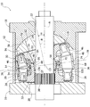
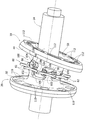
도 1은 본 발명을 따르고 분해된 유압 기계를 도시한 축 방향 횡단면도.
도 2는 도 1에 도시되고 분해된 유압 기계를 도시한 축 방향 횡단면도.
도 3은 도 2의 화살표(III)로 표시되고 분해된 부품들을 도시한 사시도.
도 4는 도 3의 화살표(IV)로 표시된 부분을 횡단면으로 도시한 사시도.
도 5는 일부 부품들이 제거되고 도 3의 화살표(IV)로 표시된 부분을 도시한 사시도.
도 6은, 도 3의 화살표(IV)로 표시되고 분해된 부품들을 도시한 사시도.
도 7은, 본 발명을 따르는 유압 기계의 제1 및 제2 로터들사이에 배열된 등속 조인트(constant velocity joint)를 도시한 사시도.
도 8은, 본 발명을 따르는 기계내에서 유압 연결부를 도시한 축 방향 횡단면도.
도 9는 본 발명을 따르는 기계의 변위를 조정하는 조정장치를 도시한 사시도.BRIEF DESCRIPTION OF THE DRAWINGS Figure 1 is an axial cross-sectional view of a disassembled hydraulic machine according to the present invention;
2 is an axial cross-sectional view of the hydraulic machine shown and broken in Fig.
Fig. 3 is a perspective view showing parts broken down and represented by arrow III in Fig. 2; Fig.
Fig. 4 is a perspective view showing a cross section of a portion indicated by an arrow IV in Fig. 3; Fig.
Fig. 5 is a perspective view showing some parts removed and indicated by the arrow (IV) in Fig. 3;
Fig. 6 is a perspective view showing the components shown and disassembled by arrow IV in Fig. 3; Fig.
Figure 7 is a perspective view showing a constant velocity joint arranged between first and second rotors of a hydraulic machine according to the present invention;
8 is an axial cross-sectional view of a hydraulic connection in a machine according to the invention;
9 is a perspective view showing an adjusting device for adjusting the displacement of a machine according to the invention;
도 1 및 도 2를 참고할 때 본 발명을 따르는 유압 기계(10)가 도시된다. 상기 유압 기계(10)는 펌프 또는 모터로서 작동할 수 있다. 상기 유압 기계(10)는 관형 중앙 몸체(14), 제1 전방 판(16) 및 제2 전방 판(18)을 포함한 정지상태의 케이싱(12)을 가진다. 상기 제1 및 제2 전방 판(16,18)들은 상기 중앙 몸체(14)의 마주보는 단부들에 고정된다. 상기 제1 및 제2 전방 판(16,18)들은, 주축(A) 주위에서 상기 케이싱(12)에 대해 회전가능한 샤프트(24)를 회전상태에서 지지하는 (도면에 도시되지 않는) 베어링과 밀봉체(seals)를 위한 각각의 시트(seat)(20,22)들을 가진다.Referring to Figures 1 and 2, a
상기 케이싱(12)은 챔버(26)를 형성하고, 상기 챔버내에 제1 로터(28) 및 제2 로터(30)가 배열된다.The
상기 제1 로터(28)는, 제1 로터 몸체(32) 및 상기 제1 로터 몸체(32)에 고정된 복수 개의 제1 피스톤(34)들을 포함한다. 상기 제1 로터 몸체(32)는 상기 샤프트(24)의 스플라인 부분(splined portion)(38)과 연결된 스플라인 구멍(37)을 가진다. 따라서, 제1 로터(38)는 상기 샤프트(24)에 대해 회전상태로 고정된다.The
상기 제1 피스톤(34)은 상기 제1 로터 몸체(32)에 대해 캔틸레버 지지되어 고정되고 상기 주축(A)에 대해 평행한 각각의 종 방향 축들을 가진다. 상기 제1 피스톤(34)은, 상기 제1 로터 몸체(32)에 대해 원위(distal) 배열된 각각의 구형 링 헤드(ring head)(36)를 가진다. 상기 제1 로터 몸체(32)는, 상기 제1 전방 판(16)의 해당 지지 표면(42)에 대하여 유압 밀봉 접촉(sealing contact) 상태로 배열된 반경 방향의 지지 표면(40)을 가진다. 작동하는 동안, 상기 제1 로터 몸체(32)의 반경 방향 지지표면(40)은 상기 제1 전방 판(16)의 지지 표면(42)과 접촉한 상태로 회전한다.The
제2 로터(30)는 제2 로터 몸체(44) 및 복수 개의 제2 피스톤(46)을 포함한다. 상기 제2 피스톤(46)은 상기 제2 로터 몸체(44)에 고정된다. 상기 제2 피스톤(46)은 상기 제2 로터 몸체(44)로부터 캔틸레버 지지되어 돌출하고 상기 제2 로터 몸체(44)에 대해 원위 배열된 각각의 구형 링 헤드(48)를 가진다. 구조적인 관점에서 볼 때, 상기 제2 피스톤(46)은 상기 제1 피스톤(34)과 동일할 수 있다.The second rotor (30) includes a second rotor body (44) and a plurality of second pistons (46). The second piston (46) is fixed to the second rotor body (44). The
상기 제2 로터 몸체(44)는 중앙 개구부(50)를 가지고, 상기 중앙 개구부를 통해 상기 샤프트(24)가 연장된다. 상기 제2 로터 몸체(44)의 중앙 개구부(50)는 실질적으로 상기 샤프트(24)의 직경보다 큰 치수를 가진다. 상기 제2 로터 몸체(44)의 중앙 개구부(50)는 상기 제2 로터(30)가 제2 축(B) 주위에서 회전하는 것을 허용하는 치수를 가지고, 상기 제2축은 상기 주축(A)에 대해 0°에 해당하는 최소값(상기 제2 축(B)이 상기 주축(A)과 정렬되는 상태), 도 1에 도시된 양의 최대 각도(α) 및 음의 최대각(-α)사이에서 변할 수 있는 각도로 기울어진다.The second rotor body (44) has a central opening (50) through which the shaft (24) extends. The central opening (50) of the second rotor body (44) has a dimension that is substantially larger than the diameter of the shaft (24). A central opening (50) of the second rotor body (44) has a dimension allowing the second rotor (30) to rotate about a second axis (B) (A state in which the second axis B is aligned with the main axis A), a minimum value corresponding to 0 占 between the maximum angle? And the maximum negative angle? It tilts at a variable angle.
상기 제2 전방 판(18)은 상기 주축(A)에 대해 직교하는 축을 가진 오목한 반 원통형 시트(52)를 가진다. 조정 판(54)이 상기 제2 로터 몸체(44) 및 제2 전방 판(18)사이에 배열된다. 상기 조정 판(54)은 상기 제2 전방 판(18)의 오목한 반 원통형의 시트(52)와 연결되는 볼록한 반 원통형의 표면(56)을 가진다. 상기 조정 판(54)은 지지 표면(58)을 가지고, 상기 제2 로터 몸체(44)의 해당 지지 표면(60)이 유압 밀봉 접촉하면서 상기 지지 표면(58)에 대해 배열된다. 상기 조정 판(54)은 상기 샤프트(24)가 가로지르는 중앙 개구부(62)를 가진다. 상기 중앙 개구부(62)는 실질적으로 상기 샤프트(24)의 직경보다 큰 치수를 가져서 상기 조정 판(54)은 상기 주축(A)에 대해 복수 개의 경사 위치를 가질 수 있다.The second front plate (18) has a concave semi-cylindrical sheet (52) having an axis orthogonal to the main axis (A). The
작동하는 동안, 일정한 변위에서 상기 조정 판(54)은 상기 제2 전방 판(18)에 대해 고정된 위치에 배열된다. 상기 제2 로터(30)는 상기 조정 판(54)에 대해 가압되고 상기 조정 판(54)은 상기 시트(52)에 대해 가압되어 지지 표면(58,60,56,52)들은 지속적으로 유압 밀봉 접촉에 의해 서로 접촉한다. 상기 제2 전방 판(18)에 대한 상기 조정 판(54)의 각 위치는, 상기 제2 로터(30)의 제2 회전축(B) 및 주축(A)사이에서 각도(α)를 결정한다.During operation, the adjusting
도 9를 참고할 때, 본 발명을 제한하지 않는 실시예에 따라 상기 조정 판(54)은 상기 제2 전방 판(18)에 대해 상기 조정 판(54)의 각 위치를 조정하는 액추에이터(64)와 연결된다. 도 9에 도시된 예에서 상기 액추에이터(64)는 회전식(rotary) 액추에이터이고, 상기 액추에이터는 샤프트(66)를 회전구동하며, 상기 조정 판(54)에 제공된 치형 부분(toothed portion)(70)과 함께 작동하는 나사(68)가 상기 샤프트(66)에 고정된다. 상기 액추에이터(64)는, 상기 주축(A)과 직교하는 축 주위에서 상기 조정 판(54)의 진동을 제어한다. 상기 제2 로터(30)가 상기 조정 판(54)의 지지 표면(58)과 접촉한 상태를 유지하도록 구속되기 때문에 상기 조정 판(54)의 진동 운동은 상기 주축(A) 및 상기 제2 로터(30)의 회전축(B)사이의 각도(α)를 조정한다.9, the
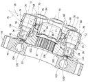
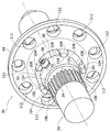
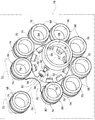
도 3 및 도 4를 참고할 때, 기계(10)는, 서로 분리되고 독립적인 복수 개의 슬리브(68)들을 포함한다. 각각의 슬리브는 양쪽 단부들을 향해 개방된 각각의 실린더(70)를 가진다. 각각의 슬리브(70)는 각각의 제1 피스톤(34) 및 각각의 제2 피스톤(46)에 의해 마주보는 측부들에 연결된다. 상기 피스톤(34,36)들의 구형 헤드(36,38)들은 각각의 실린더(70)의 벽들과 유압 밀봉 접촉(hydraulic sealing contact)을 형성한다.3 and 4, the
특히 도 4를 참고할 때, 각각의 슬리브(68)는 실린더(70)의 종 방향 축(D)과 수직인 실린더(70)의 대칭면으로서 형성되는 각각의 횡 방향 대칭면(72)을 가진다. 슬리브의 외측면에서 각각의 슬리브(68)는 상기 실린더(70)의 종 방향 축(D)과 공축을 이루고 상기 중심의 횡 방향 평면(72)에 대해 대칭인 원형 그루브(74)를 가진다.4, each
도 2, 도 4 및 도 6을 참고할 때, 기계(10)는 상기 슬리브(68)와 연결된 안내 장치(76)를 포함한다. 상기 안내 장치(76)는 부유상태로 슬리브(68)와 연결되고 각각의 슬리브(68)의 중심의 횡 방향 평면(72)이 공통의 기준 평면(78)내에서 계속해서 구속되도록 상기 안내 장치는 상기 슬리브(68)를 구속한다. 상기 공통의 기준 평면(78)과 수직인 직선이, 제1 로터(28)의 회전축(A) 및 제2 로터(30)의 회전축(B)에 대해 0 내지 α의 각도 선호적으로 α/2의 각으로 기울어진다. 상기 안내 장치(76)는 복수 개의 반원형 시트(82)를 가진 안내 판(80)을 포함하고, 상기 반원형 시트는 상기 슬리브(68)의 각 그루브(74)와 연결된다. 상기 안내 판(80)의 반원형 시트(82)는 상기 슬리브(68)의 원형 그루브(74)의 반경보다 큰 반경을 가진다. 상기 반원형 시트(82)의 두께는 필수적으로 상기 슬리브(68)의 원형 그루브(74)의 두께와 동일하다. 상기 슬리브(68)는 상기 각각의 반원형 시트(82)와 단순 지지 관계를 가지며 연결된다. 상기 슬리브(68)는 상기 안내 판(80)에 대해 자유롭게 부유되며 상기 반원형 시트(82) 및 원형 그루브(74)사이에서 연결상태를 유지한다. 이렇게 하여, 개별 슬리브(68)의 중심의 횡 방향 평면(72)들은 구속되어 서로 공면(coplanar)을 유지하고 상기 안내 판(80)의 중심 평면과 일치하는 공통의 기준 평면(78)내에 구속된다.2, 4 and 6, the
상기 안내 장치(76)는 볼록한 구형 표면(86) 및 중심 구멍(88)을 가진 지지 링(84)을 포함하고, 상기 중심 구멍은 상기 샤프트(24)와 자유롭게 회전하도록 연결된다. 상기 지지 링(84)은 상기 제1 로터(28) 및 제2 로터(30)사이에서 상기 샤프트(24)상에 배열된다. 상기 구형 표면(86)의 중심(C1)은 주축(A)에 배열된다.The
특히 도 6을 참고할 때, 상기 안내 장치(76)는 각각의 오목한 구형 표면(92)을 가진 복수 개의 피트(feet)(90)를 포함하고, 상기 오목한 구형표면은 상기 지지 링(84)의 볼록한 구형 표면(86)위에 배열된다. 상기 오목한 구형 표면(92)의 곡률 반경은 상기 지지링(84)의 볼록한 구형 표면(86)이 가지는 곡률 반경과 동일하다. 상기 피트(90)는 포크(fork) 형상의 시트를 가진 각각의 스템(94)을 가지며, 상기 안내 판(80)의 반경 방향 내측 부분으로부터 돌출하는 각각의 반경 방향 치형부(96)가 상기 시트속에 삽입된다. 선호적으로 회전기능의 구형 외부 표면들을 가진 각각의 구름 몸체(98)들이 상기 피트(90)의 스템(94)에 회전가능하게 장착된다. 상기 피트(90)는 상기 지지 링(84)에 대해 상기 안내 장치(76)를 구속하여, (상기 안내 판(80)의 중심 평면과 일치하는) 공통의 기준 평면(78)이 상기 구형 표면(86)의 중심(C1)을 통해 연속적으로 통과한다. 상기 공통의 기준 평면(78)은 또한 모든 실린더(70)들의 중심(C)을 통과한다(도 4). 상기 지지 링(84)의 중심(C1)은 상기 공통의 기준 평면(78)의 위치를 형성하며 상기 지지 링(84)은 하기 방법에 따라 상기 제1 로터(28) 및 제2 로터(30)사이에 구속된다.6, the guiding
도 7을 참고할 때, 유압 기계(10)는, 상기 제1 로터(28) 및 제2 로터(30)를 서로 연결하는 등속 장치(100)를 포함한다. 상기 등속(constant- velocity) 장치(100)는, 상기 제1 로터(28) 몸체와 일체 구성되거나 고정되는 제1 일련의 전방 치형부(102) 및 상기 제2 로터 몸체(44)와 일체 구성되거나 고정되는 제2 일련의 전방 치형부(104)를 포함한다. 상기 전방 치형부(102,104)들은 상기 구름 몸체(98)의 외부 표면과 접촉하는 원통형 표면을 가진 각각의 측부(106,108)들을 가진다. 각각의 구름 몸체(98)는, 상기 제1 로터(28)의 전방 치형부(102)의 측부(106) 및 제2 로터(30)의 전방 치형부(104)의 측부(108)사이에 유지된다. 각각의 전방 치형부(102, 104)는 두 개의 인접한 구름 몸체(98)들사이에 배열된다. 상기 측부(106,108)들의 원통형 표면들이 가지는 곡률 반경은, 상기 구름 몸체(98)의 외측 표면들이 가지는 반경과 동일하다. 상기 배열은 상기 제1 로터(28) 및 제2 로터(30)사이에서 등속 전달을 형성하여, 각각의 축(A,B)들 주위에서 두 개의 로터(28,30)들이 가지는 각속도가 서로 계속적으로 동일하다.Referring to Fig. 7, the
도 5를 참고할 때, 상기 제2 로터 몸체(44)의 전방 치형부(104)는, 상기 지지 링(84)의 볼록한 구형 표면(86)에 대해 가압되고 접촉되는 오목한 구 형상을 가진 내부 표면(134)을 가진다. 도 4를 참고할 때, 압축상태의 탄성 요소(136)가 지지 링(84) 및 제1 로터 몸체(32)사이에 배열된다. 상기 탄성 요소(136)는 도 4에 도시된 웨이브 스프링(wave spring) 또는 선택적으로 나선형 스프링 또는 상기 지지 링(84) 및 제1 로터 몸체(32)사이에서 축 방향 하중을 발생시키기 위한 다른 모든 탄성 요소에 의해 형성될 수 있다. 상기 탄성 요소(136)는, 상기 전방 치형부(102)에 대해 내부에 위치한 상기 제1 로터 몸체(32)의 시트(138)내에 수용된다. 상기 탄성 요소(136)는, 상기 주축(A)의 방향을 따라 상기 지지 링(84)위에 탄성 하중을 발생시키고 상기 제2 로터 몸체(44)의 구형 표면(134)에 대해 지지 링(84)의 구형 표면(86)을 가압하고 접촉한다. 상기 실린더(70) 내에서 유압력이 없을 때 상기 탄성 요소(136)에 의해 발생되는 탄성력은, 상기 제1 로터(28) 및 제1 전방판(16)사에서 유입 밀봉을 형성하고 상기 제2 로터(30), 조정 판(34) 및 제2 전방 판(18)사이에서 유압 밀봉을 형성하기 위해 필요한 접촉하중을 발생시킨다.5, the
도 4, 도 5 및 도 7을 참고할 때, 제1 로터 몸체(32)는 제1 개구부(110)를 가지고, 각각의 제1 피스톤(34)의 루트(root) 부분들이 상기 제1 개구부내에 고정된다. 유사하게, 제2 로터 몸체(44)는 제2 개구부(112)를 가지고, 각각의 제2 피스톤(46)의 루트 부분들이 상기 제2 개구부내에 고정된다. 도 1 및 도 8에 도시된 것처럼, 상기 제1 및 제2 피스톤(34, 46)들은, 각각의 개구부(110,112)를 각각의 실린더(70)와 연결시키는 각각의 구멍(116,118)을 가진다. 도 4를 참고할 때, 상기 제1 로터 몸체(32)의 제1 개구부(110)들은 상기 제1 전방 판(16)의 지지 표면(42)내에 형성된 포트(120)들과 주기적으로 유체 교환(communication)한다. 상기 포트(120)들은 유입구/유출구 유압 유체 도관(122,124)들과 연결된다. 도 8을 참고할 때, 상기 제2 로터 몸체(44)의 개구부(112)는 상기 조정 판(54)내에 형성된 관통 개구부(126)와 주기적으로 유체 교환한다. 다음에, 상기 관통 개구부(126)들은 제2 전방 판(18)내에 형서된 포트(128)와 유체 교환하고 유입구/유출구 유체 도관(130,132)과 유체 교환한다.Referring to Figures 4, 5 and 7, the
선택적 실시예에서, 유입구/유출구 유압 유체 도관(122,124)들은 상기 제1 전방 판(16)내에서만 제공될 수 있다. 이 경우, 제2 전방판(18)은 유압 도관(130, 132)들을 가지지 않을 수 있다. 이 경우, 제2 피스톤(46)의 구멍(118)은 구멍(118)내부에 삽입된 밀폐 요소들에 의해 부분적으로 채워져서 실린더(70)내에서 오일의 체적을 제한한다. 상기 관통 개구부(126)는 하중을 보상하기 위한 연결부를 빈 상태로 남겨놓는다.In an alternative embodiment, the inlet / outlet hydraulic
유압 기계(10)는 유압 펌프 또는 유압 모터로서 유사하게 작동한다. 양쪽 작동 모드들에서, 조정판(54)의 경사각(α)은 기계의 작동 변위를 결정한다. 상기 제2 회전축(B) 및 상기 주축(A)사이의 각도(α)가 영( 두 개의 축들이 일치하는 상태)일 때 상기 작동 변위는 영이다. 상기 회전축(B,A)들사이의 각도(α)가 최대 작동 각과 동일할 때 상기 작동 변위는 최대값을 가진다. 액추에이터(64)에 의해 상기 조정 판(54)의 경사각을 -α 내지 +α로 변화시켜서 기계의 변위가 음의 최대값 및 양의 최대값사이에서 계속해서 변화할 수 있다.The
상기 각(α)이 영과 다른 위치에서, 상기 로터(28,30)들이 각각의 회전축(A,B) 주위에서 회전하면, 각각의 실린더(70)내부에 배열된 피스톤(34,46)들이 서로 이격된 위치 및 서로 근접한 위치사이에서 교대로 운동한다. 상기 운동에 의해 상기 실린더의 체적은 두 개의 피스톤(34,46)들사이에서 주기적으로 변화한다. 상기 실린더(70)의 체적이 주기적으로 변화하면, 펌프로서 작동하는 경우에 유동이 발생되고 모터로서 작동하는 경우에 작업 토크가 발생된다.When the
물론, 본 발명의 원리에 편향되지 않고 상기 상세한 설명 및 실시예에 관한 설명은 하기 청구범위에 정의된 본 발명의 범위내에서 상기 설명과 도면에 대해 변경될 수 있다.Of course, without intending to be bound by the principles of the present invention, the foregoing description and the description of embodiments may be varied from the above description and drawings within the scope of the present invention as defined in the following claims.
16.......제1 전방 판,
18.......제2 전방 판,
12.......외부 케이싱,
24.......샤프트,
32.......제1 로터 몸체,
38.......구형 링 헤드,
44.......제2 로터 몸체,
48.......구형 링 헤드,
46.......제2 피스톤,
30.......제2 로터,
68.......슬리브,
70.......실린더,
72.......횡 방향 대칭 평면,
78.......공통의 기준 평면.16: a first front plate,
18 ... second front plate,
12 ... outer casing,
24 ....... shaft,
32: a first rotor body,
38 ....... spherical ring head,
44 ... the second rotor body,
48 ....... spherical ring head,
46: a second piston,
30 ... second rotor,
68 ....... Sleeve,
70 ....... cylinder,
72 ......... lateral symmetry plane,
78 ....... common reference plane.
Claims (13)
주축(A) 주위에서 상기 제1 및 제2 전방 판(16,18)에 의해 회전가능하게 배열된 샤프트(24),
상기 주축(A) 주위에서 상기 샤프트(24)와 회전가능한 제1 로터 몸체(32)를 포함하고 상기 제1 로터 몸체(32)에 고정되고 각각의 구형 링 헤드(36)들을 가진 복수 개의 제1 피스톤(34)들을 포함한 제1 로터(28),
제2 로터 몸체(44)를 포함하고 각각의 구형 링 헤드(48)를 가진 복수 개의 제2 피스톤(46)들을 포함한 제2 로터(30)를 포함하고, 상기 제2 로터(30)는 제2 축(B) 주위에서 회전가능하고 상기 주축(A)에 대해 기울어지며,
서로 분리되고 독립적인 복수 개의 슬리브(68)들을 포함하고, 각각의 슬리브는 마주보는 단부들에서 개방되고 제1 피스톤(34)과 제2 피스톤(46)에 의해 마주보는 측부들에 연결되는 실린더(70)를 가지며,
상기 제1 피스톤(34)과 제2 피스톤(46)의 구형 링 헤드(36,48)들은 상기 실린더(70)와 유압 밀봉 접촉되고, 각각의 슬리브(68)는 상기 실린더(70)의 종 방향 축(D)에 대해 직교하는 각각의 횡 방향 대칭 평면(72)을 가지며, 상기 개별 슬리브(68)의 횡 방향 대칭 평면(72)들이 공통의 기준 평면(78)내에 계속해서 구속되도록 상기 슬리브(68)들과 부유 상태로 연결되고 상기 슬리브(68)들을 구속하는 안내 장치(76)를 포함하는 것을 특징으로 하는 유압 기계.
An outer casing 12 including a first front plate 16 and a second front plate 18,
A shaft 24 rotatably arranged around the main axis A by the first and second front plates 16 and 18,
A first rotor body (32) rotatable with said shaft (24) about said main axis (A) and being fixed to said first rotor body (32) and having a plurality of first ring heads A first rotor 28 including pistons 34,
And a second rotor (30) including a second rotor body (44) and including a plurality of second pistons (46) each having a respective spherical ring head (48), said second rotor (30) Is rotatable about an axis (B) and is inclined with respect to the main axis (A)
Each of the sleeves comprising a cylinder (68) which is open at opposite ends and which is connected to the sides facing by the first piston (34) and the second piston (46) 70,
The spherical ring heads 36 and 48 of the first piston 34 and the second piston 46 are in hydraulic hermetic contact with the cylinder 70 and each sleeve 68 is in hydraulic contact with the cylinder 70 in the longitudinal direction (72) having respective transverse symmetry planes (72) orthogonal to the axis (D) such that the transverse symmetry planes (72) of the individual sleeves (68) And a guide device (76) connected in suspension with said sleeves (68) and restricting said sleeves (68).
The guide device according to claim 1, wherein the guide device includes a guide plate having a plurality of semicircular sheets, each of the circular grooves formed on an outer surface of the sleeve, Wherein the circular grooves 74 are symmetrical with respect to the transverse plane 72 of each central axis and coaxial with the longitudinal axis D of the sleeve 68.
3. The apparatus of claim 2, wherein the guide device (76) comprises a support ring (84) coaxial with the shaft (24) and arranged between the first rotor (38) and the second rotor The support ring 84 has a convex spherical outer surface 86 on which each support pit 90 is supported and the support peg connects the rectangular cross section 96 of the guide plate 80 to each radial tooth Wherein the hydraulic cylinder has a stem for allowing the hydraulic cylinder to move.
4. Hydraulic machine according to claim 3, characterized in that the second rotor body (44) has a concave spherical surface (134) supported on the convex spherical surface (86) of the support ring (84).
5. Hydraulic machine according to claim 4, characterized in that a compressed elastic element (136) is arranged between said support ring (84) and said first rotor body (40).
6. A rotary compressor according to any one of claims 1 to 5, characterized in that it comprises a first cylinder (52) housed in a cylindrical seat (52) of the second front plate (18) Characterized in that said second rotor body (30) is arranged with respect to an adjusting plate (54) connected to an actuator (64).
2. The rotor of claim 1 including a first set of front teeth (102) formed on the first rotor body (32) and a second set of front teeth (104) formed on the second rotor body The first and second front teeth (102, 104) are connected to each other by a constant velocity device (100) such that the first and second rotors (28, 30) Has side portions (106,108).
The hydraulic machine according to claim 7 or claim 3, characterized in that the rolling body (98) is rotatably mounted on each stem (94) of the pit (90) of the guiding device (76).
9. A method according to any one of claims 1 to 8, wherein the first piston (34) comprises a respective hole (116) connecting the cylinder (70) to the opening (110) of the first rotor body (32) Wherein the openings are periodically in fluid communication with the ports (120) of the first front plate (16) and the ports are in fluid communication with the inlet / outlet hydraulic fluid conduits (122,124).
10. A compressor according to any one of claims 1 to 9, wherein the second pistons (46) have respective openings (118) connecting the cylinders (70) to the openings (112) of the second rotor body , Said openings being periodically fluid-exchanged with through openings (126) arranged in said regulating plate (54) and arranged to fluidly exchange with the ports (128) of said second front plate (18) Ports are in fluid communication with the inlet / outlet hydraulic fluid conduits (130,132).
4. The apparatus of claim 3 wherein the pits 90 restrain the guide plate 76 against the support ring 84 such that a common reference plane 78 is defined by the convex spherical surface 86 of the support ring 84. [ And passes through the center C of the cylinder 70 and the support ring 84 is confined between the first rotor 28 and the second rotor 30. [ Hydraulic machine.
4. The apparatus according to claim 3, wherein the pits (90) restrain the guide plate (76) against the support ring (84) so that a common reference plane (78) coincides with the central plane of the guide plate Features a hydraulic machine.
13. The method according to any one of claims 1 to 12, wherein the common reference plane (76) and the common reference plane (76) are formed with respect to the rotational axis (A) of the first rotor (28) The vertical straight line is inclined at an angle? / 2 corresponding to half of the angle? Between the rotation axis A of the first rotor 28 and the rotation axis B of the second rotor 30 Wherein the hydraulic motor is arranged in the first direction.
Applications Claiming Priority (2)
| Application Number | Priority Date | Filing Date | Title |
|---|---|---|---|
| ITUB2015A005999A ITUB20155999A1 (en) | 2015-11-30 | 2015-11-30 | HYDRAULIC FLOATING CYLINDER MACHINE |
| IT102015000078409 | 2015-11-30 |
Publications (1)
| Publication Number | Publication Date |
|---|---|
| KR20170063386A true KR20170063386A (en) | 2017-06-08 |
Family
ID=55485192
Family Applications (1)
| Application Number | Title | Priority Date | Filing Date |
|---|---|---|---|
| KR1020160159065A KR20170063386A (en) | 2015-11-30 | 2016-11-28 | A hydraulic machine with floating cylinders |
Country Status (7)
| Country | Link |
|---|---|
| US (1) | US10400742B2 (en) |
| EP (1) | EP3179101B1 (en) |
| JP (1) | JP6787556B2 (en) |
| KR (1) | KR20170063386A (en) |
| CN (1) | CN106907308B (en) |
| ES (1) | ES2685946T3 (en) |
| IT (1) | ITUB20155999A1 (en) |
Families Citing this family (3)
| Publication number | Priority date | Publication date | Assignee | Title |
|---|---|---|---|---|
| WO2019190440A2 (en) * | 2018-01-25 | 2019-10-03 | Ali̇ Kilinç Metal Hobi̇ Model Araçlar Ve Oyuncak İmalat İthalat İhracat Sanayi̇ Ti̇caret Anoni̇m Şi̇rketi̇ | Hydraulic motor configuration that provides high efficiency at low bar values |
| US10968741B2 (en) * | 2019-02-08 | 2021-04-06 | Volvo Car Corporation | Variable pre and de-compression control mechanism and method for hydraulic displacement pump |
| ES2937207B2 (en) * | 2021-09-23 | 2023-07-31 | Moran Emiliano Fernandez | AXIAL PISTON PUMP |
Family Cites Families (12)
| Publication number | Priority date | Publication date | Assignee | Title |
|---|---|---|---|---|
| JPS5929765U (en) * | 1982-08-18 | 1984-02-24 | 住友重機械工業株式会社 | Swash plate type hydraulic pump/motor rotation detection device |
| JPS6163485U (en) * | 1984-09-30 | 1986-04-30 | ||
| CN85103883A (en) * | 1985-05-10 | 1987-01-14 | 株式会社日立制作所 | Hydraulic press |
| JPS62170782A (en) * | 1986-01-22 | 1987-07-27 | Shimadzu Corp | Flow rate synchronizer |
| DE10124031B4 (en) * | 2001-05-16 | 2009-08-20 | Daimler Ag | Reciprocating engine with a driver |
| NL1020932C2 (en) * | 2002-01-12 | 2003-07-15 | Innas Bv | Hydraulic device. |
| CN101424282B (en) * | 2008-11-05 | 2011-05-18 | 北京理工大学 | Inclined shaft type hydraulic transformer and voltage transformation method |
| WO2013087666A1 (en) * | 2011-12-15 | 2013-06-20 | Robert Bosch Gmbh | Hydrostatic axial piston machine |
| DE102012006289A1 (en) * | 2012-03-29 | 2013-10-02 | Robert Bosch Gmbh | Hydrostatic axial piston machine |
| JP6114089B2 (en) * | 2013-03-29 | 2017-04-12 | Kyb株式会社 | Opposite swash plate type piston pump / motor |
| DE102013222602A1 (en) * | 2013-11-07 | 2015-05-07 | Robert Bosch Gmbh | Hydrostatic axial piston machine |
| DE102014104953A1 (en) * | 2014-04-08 | 2015-10-08 | Linde Hydraulics Gmbh & Co. Kg | Hydrostatic axial piston machine in bent-axis design with a follower joint for driving the cylinder drum |
-
2015
- 2015-11-30 IT ITUB2015A005999A patent/ITUB20155999A1/en unknown
-
2016
- 2016-11-23 EP EP16200148.1A patent/EP3179101B1/en active Active
- 2016-11-23 ES ES16200148.1T patent/ES2685946T3/en active Active
- 2016-11-28 JP JP2016230695A patent/JP6787556B2/en active Active
- 2016-11-28 KR KR1020160159065A patent/KR20170063386A/en not_active Application Discontinuation
- 2016-11-30 CN CN201611090599.8A patent/CN106907308B/en active Active
- 2016-11-30 US US15/364,501 patent/US10400742B2/en active Active
Also Published As
| Publication number | Publication date |
|---|---|
| CN106907308A (en) | 2017-06-30 |
| US10400742B2 (en) | 2019-09-03 |
| JP2017125494A (en) | 2017-07-20 |
| CN106907308B (en) | 2020-03-27 |
| ITUB20155999A1 (en) | 2017-05-30 |
| ES2685946T3 (en) | 2018-10-15 |
| JP6787556B2 (en) | 2020-11-18 |
| EP3179101A1 (en) | 2017-06-14 |
| EP3179101B1 (en) | 2018-06-13 |
| US20170152832A1 (en) | 2017-06-01 |
Similar Documents
| Publication | Publication Date | Title |
|---|---|---|
| ES2230055T3 (en) | ROTATING POWER UNIT. | |
| US20190293118A1 (en) | System and method for hydrostatic bearings | |
| JP6333553B2 (en) | Fluid device including a face plate | |
| JP2015507158A (en) | Rotary actuator | |
| US20080060510A1 (en) | Variable pump or hydraulic motor | |
| JP2007503543A5 (en) | ||
| KR20170063386A (en) | A hydraulic machine with floating cylinders | |
| EP2872779B1 (en) | Hydraulic radial piston devices | |
| CN106964533A (en) | The oscillation drive of pulse generation device with hydraulic pressure | |
| JP5398786B2 (en) | Micro compressor | |
| JP4813367B2 (en) | Hydraulic motor / pump | |
| KR20160116950A (en) | Lever twin cylinder pump | |
| KR101700918B1 (en) | twin circle positive-displacement pump | |
| ES2932663T3 (en) | A sliding vane rotary machine with hydrostatic slide bearings for the vanes | |
| JP6951590B2 (en) | Hydraulic system | |
| JP2018505347A (en) | Process pump with crank mechanism | |
| JP6611453B2 (en) | Oblique shaft type axial piston machine with slide shoe on transmission flange | |
| JP6526600B2 (en) | Piston type compressor | |
| JP2019529769A (en) | Rotary piston and cylinder device | |
| KR101724653B1 (en) | Twin circle positive-displacement pump | |
| US10273946B2 (en) | Rotary fluid device with bent cylinder sleeves | |
| KR20030068890A (en) | Swash plate type axial piston apparatus | |
| KR101724657B1 (en) | Twin circle positive-displacement pump | |
| RU2004849C1 (en) | Positive-displacement machine | |
| KR20150084889A (en) | Vane pumps and methods of operating same |
Legal Events
| Date | Code | Title | Description |
|---|---|---|---|
| A201 | Request for examination | ||
| E902 | Notification of reason for refusal | ||
| E90F | Notification of reason for final refusal |