JP4813367B2 - Hydraulic motor / pump - Google Patents
Hydraulic motor / pump Download PDFInfo
- Publication number
- JP4813367B2 JP4813367B2 JP2006544172A JP2006544172A JP4813367B2 JP 4813367 B2 JP4813367 B2 JP 4813367B2 JP 2006544172 A JP2006544172 A JP 2006544172A JP 2006544172 A JP2006544172 A JP 2006544172A JP 4813367 B2 JP4813367 B2 JP 4813367B2
- Authority
- JP
- Japan
- Prior art keywords
- crankshaft
- cylinder
- main bearing
- hydraulic machine
- piston
- Prior art date
- Legal status (The legal status is an assumption and is not a legal conclusion. Google has not performed a legal analysis and makes no representation as to the accuracy of the status listed.)
- Expired - Fee Related
Links
Images


Classifications
-
- F—MECHANICAL ENGINEERING; LIGHTING; HEATING; WEAPONS; BLASTING
- F03—MACHINES OR ENGINES FOR LIQUIDS; WIND, SPRING, OR WEIGHT MOTORS; PRODUCING MECHANICAL POWER OR A REACTIVE PROPULSIVE THRUST, NOT OTHERWISE PROVIDED FOR
- F03C—POSITIVE-DISPLACEMENT ENGINES DRIVEN BY LIQUIDS
- F03C1/00—Reciprocating-piston liquid engines
- F03C1/02—Reciprocating-piston liquid engines with multiple-cylinders, characterised by the number or arrangement of cylinders
- F03C1/04—Reciprocating-piston liquid engines with multiple-cylinders, characterised by the number or arrangement of cylinders with cylinders in star or fan arrangement
- F03C1/0403—Details, component parts specially adapted of such engines
- F03C1/0406—Pistons
-
- F—MECHANICAL ENGINEERING; LIGHTING; HEATING; WEAPONS; BLASTING
- F03—MACHINES OR ENGINES FOR LIQUIDS; WIND, SPRING, OR WEIGHT MOTORS; PRODUCING MECHANICAL POWER OR A REACTIVE PROPULSIVE THRUST, NOT OTHERWISE PROVIDED FOR
- F03C—POSITIVE-DISPLACEMENT ENGINES DRIVEN BY LIQUIDS
- F03C1/00—Reciprocating-piston liquid engines
- F03C1/02—Reciprocating-piston liquid engines with multiple-cylinders, characterised by the number or arrangement of cylinders
- F03C1/04—Reciprocating-piston liquid engines with multiple-cylinders, characterised by the number or arrangement of cylinders with cylinders in star or fan arrangement
- F03C1/0447—Controlling
- F03C1/0457—Controlling by changing the effective piston stroke
- F03C1/046—Controlling by changing the effective piston stroke by changing the excentricity of one element relative to another element
-
- F—MECHANICAL ENGINEERING; LIGHTING; HEATING; WEAPONS; BLASTING
- F03—MACHINES OR ENGINES FOR LIQUIDS; WIND, SPRING, OR WEIGHT MOTORS; PRODUCING MECHANICAL POWER OR A REACTIVE PROPULSIVE THRUST, NOT OTHERWISE PROVIDED FOR
- F03C—POSITIVE-DISPLACEMENT ENGINES DRIVEN BY LIQUIDS
- F03C1/00—Reciprocating-piston liquid engines
- F03C1/003—Reciprocating-piston liquid engines controlling
- F03C1/005—Reciprocating-piston liquid engines controlling motor piston stroke control
-
- F—MECHANICAL ENGINEERING; LIGHTING; HEATING; WEAPONS; BLASTING
- F03—MACHINES OR ENGINES FOR LIQUIDS; WIND, SPRING, OR WEIGHT MOTORS; PRODUCING MECHANICAL POWER OR A REACTIVE PROPULSIVE THRUST, NOT OTHERWISE PROVIDED FOR
- F03C—POSITIVE-DISPLACEMENT ENGINES DRIVEN BY LIQUIDS
- F03C1/00—Reciprocating-piston liquid engines
- F03C1/02—Reciprocating-piston liquid engines with multiple-cylinders, characterised by the number or arrangement of cylinders
- F03C1/04—Reciprocating-piston liquid engines with multiple-cylinders, characterised by the number or arrangement of cylinders with cylinders in star or fan arrangement
- F03C1/0403—Details, component parts specially adapted of such engines
- F03C1/0415—Cylinders
-
- F—MECHANICAL ENGINEERING; LIGHTING; HEATING; WEAPONS; BLASTING
- F03—MACHINES OR ENGINES FOR LIQUIDS; WIND, SPRING, OR WEIGHT MOTORS; PRODUCING MECHANICAL POWER OR A REACTIVE PROPULSIVE THRUST, NOT OTHERWISE PROVIDED FOR
- F03C—POSITIVE-DISPLACEMENT ENGINES DRIVEN BY LIQUIDS
- F03C1/00—Reciprocating-piston liquid engines
- F03C1/02—Reciprocating-piston liquid engines with multiple-cylinders, characterised by the number or arrangement of cylinders
- F03C1/04—Reciprocating-piston liquid engines with multiple-cylinders, characterised by the number or arrangement of cylinders with cylinders in star or fan arrangement
- F03C1/053—Reciprocating-piston liquid engines with multiple-cylinders, characterised by the number or arrangement of cylinders with cylinders in star or fan arrangement the pistons co-operating with an actuated element at the inner ends of the cylinders
- F03C1/0535—Reciprocating-piston liquid engines with multiple-cylinders, characterised by the number or arrangement of cylinders with cylinders in star or fan arrangement the pistons co-operating with an actuated element at the inner ends of the cylinders with two or more radial piston/cylinder units in series
-
- F—MECHANICAL ENGINEERING; LIGHTING; HEATING; WEAPONS; BLASTING
- F04—POSITIVE - DISPLACEMENT MACHINES FOR LIQUIDS; PUMPS FOR LIQUIDS OR ELASTIC FLUIDS
- F04B—POSITIVE-DISPLACEMENT MACHINES FOR LIQUIDS; PUMPS
- F04B1/00—Multi-cylinder machines or pumps characterised by number or arrangement of cylinders
- F04B1/04—Multi-cylinder machines or pumps characterised by number or arrangement of cylinders having cylinders in star- or fan-arrangement
- F04B1/0404—Details or component parts
- F04B1/0408—Pistons
-
- F—MECHANICAL ENGINEERING; LIGHTING; HEATING; WEAPONS; BLASTING
- F04—POSITIVE - DISPLACEMENT MACHINES FOR LIQUIDS; PUMPS FOR LIQUIDS OR ELASTIC FLUIDS
- F04B—POSITIVE-DISPLACEMENT MACHINES FOR LIQUIDS; PUMPS
- F04B1/00—Multi-cylinder machines or pumps characterised by number or arrangement of cylinders
- F04B1/04—Multi-cylinder machines or pumps characterised by number or arrangement of cylinders having cylinders in star- or fan-arrangement
- F04B1/0404—Details or component parts
- F04B1/0421—Cylinders
-
- F—MECHANICAL ENGINEERING; LIGHTING; HEATING; WEAPONS; BLASTING
- F04—POSITIVE - DISPLACEMENT MACHINES FOR LIQUIDS; PUMPS FOR LIQUIDS OR ELASTIC FLUIDS
- F04B—POSITIVE-DISPLACEMENT MACHINES FOR LIQUIDS; PUMPS
- F04B1/00—Multi-cylinder machines or pumps characterised by number or arrangement of cylinders
- F04B1/04—Multi-cylinder machines or pumps characterised by number or arrangement of cylinders having cylinders in star- or fan-arrangement
- F04B1/053—Multi-cylinder machines or pumps characterised by number or arrangement of cylinders having cylinders in star- or fan-arrangement with actuating or actuated elements at the inner ends of the cylinders
- F04B1/0536—Multi-cylinder machines or pumps characterised by number or arrangement of cylinders having cylinders in star- or fan-arrangement with actuating or actuated elements at the inner ends of the cylinders with two or more serially arranged radial piston-cylinder units
-
- F—MECHANICAL ENGINEERING; LIGHTING; HEATING; WEAPONS; BLASTING
- F04—POSITIVE - DISPLACEMENT MACHINES FOR LIQUIDS; PUMPS FOR LIQUIDS OR ELASTIC FLUIDS
- F04B—POSITIVE-DISPLACEMENT MACHINES FOR LIQUIDS; PUMPS
- F04B1/00—Multi-cylinder machines or pumps characterised by number or arrangement of cylinders
- F04B1/04—Multi-cylinder machines or pumps characterised by number or arrangement of cylinders having cylinders in star- or fan-arrangement
- F04B1/06—Control
- F04B1/07—Control by varying the relative eccentricity between two members, e.g. a cam and a drive shaft
-
- F—MECHANICAL ENGINEERING; LIGHTING; HEATING; WEAPONS; BLASTING
- F04—POSITIVE - DISPLACEMENT MACHINES FOR LIQUIDS; PUMPS FOR LIQUIDS OR ELASTIC FLUIDS
- F04B—POSITIVE-DISPLACEMENT MACHINES FOR LIQUIDS; PUMPS
- F04B49/00—Control, e.g. of pump delivery, or pump pressure of, or safety measures for, machines, pumps, or pumping installations, not otherwise provided for, or of interest apart from, groups F04B1/00 - F04B47/00
- F04B49/12—Control, e.g. of pump delivery, or pump pressure of, or safety measures for, machines, pumps, or pumping installations, not otherwise provided for, or of interest apart from, groups F04B1/00 - F04B47/00 by varying the length of stroke of the working members
- F04B49/123—Control, e.g. of pump delivery, or pump pressure of, or safety measures for, machines, pumps, or pumping installations, not otherwise provided for, or of interest apart from, groups F04B1/00 - F04B47/00 by varying the length of stroke of the working members by changing the eccentricity of one element relative to another element
- F04B49/125—Control, e.g. of pump delivery, or pump pressure of, or safety measures for, machines, pumps, or pumping installations, not otherwise provided for, or of interest apart from, groups F04B1/00 - F04B47/00 by varying the length of stroke of the working members by changing the eccentricity of one element relative to another element by changing the eccentricity of the actuation means, e.g. cams or cranks, relative to the driving means, e.g. driving shafts
- F04B49/126—Control, e.g. of pump delivery, or pump pressure of, or safety measures for, machines, pumps, or pumping installations, not otherwise provided for, or of interest apart from, groups F04B1/00 - F04B47/00 by varying the length of stroke of the working members by changing the eccentricity of one element relative to another element by changing the eccentricity of the actuation means, e.g. cams or cranks, relative to the driving means, e.g. driving shafts with a double eccenter mechanism
-
- F—MECHANICAL ENGINEERING; LIGHTING; HEATING; WEAPONS; BLASTING
- F04—POSITIVE - DISPLACEMENT MACHINES FOR LIQUIDS; PUMPS FOR LIQUIDS OR ELASTIC FLUIDS
- F04B—POSITIVE-DISPLACEMENT MACHINES FOR LIQUIDS; PUMPS
- F04B53/00—Component parts, details or accessories not provided for in, or of interest apart from, groups F04B1/00 - F04B23/00 or F04B39/00 - F04B47/00
- F04B53/006—Crankshafts
-
- F—MECHANICAL ENGINEERING; LIGHTING; HEATING; WEAPONS; BLASTING
- F04—POSITIVE - DISPLACEMENT MACHINES FOR LIQUIDS; PUMPS FOR LIQUIDS OR ELASTIC FLUIDS
- F04B—POSITIVE-DISPLACEMENT MACHINES FOR LIQUIDS; PUMPS
- F04B9/00—Piston machines or pumps characterised by the driving or driven means to or from their working members
- F04B9/02—Piston machines or pumps characterised by the driving or driven means to or from their working members the means being mechanical
-
- F—MECHANICAL ENGINEERING; LIGHTING; HEATING; WEAPONS; BLASTING
- F05—INDEXING SCHEMES RELATING TO ENGINES OR PUMPS IN VARIOUS SUBCLASSES OF CLASSES F01-F04
- F05B—INDEXING SCHEME RELATING TO WIND, SPRING, WEIGHT, INERTIA OR LIKE MOTORS, TO MACHINES OR ENGINES FOR LIQUIDS COVERED BY SUBCLASSES F03B, F03D AND F03G
- F05B2210/00—Working fluid
- F05B2210/10—Kind or type
- F05B2210/11—Kind or type liquid, i.e. incompressible
-
- F—MECHANICAL ENGINEERING; LIGHTING; HEATING; WEAPONS; BLASTING
- F05—INDEXING SCHEMES RELATING TO ENGINES OR PUMPS IN VARIOUS SUBCLASSES OF CLASSES F01-F04
- F05B—INDEXING SCHEME RELATING TO WIND, SPRING, WEIGHT, INERTIA OR LIKE MOTORS, TO MACHINES OR ENGINES FOR LIQUIDS COVERED BY SUBCLASSES F03B, F03D AND F03G
- F05B2260/00—Function
- F05B2260/40—Transmission of power
-
- Y—GENERAL TAGGING OF NEW TECHNOLOGICAL DEVELOPMENTS; GENERAL TAGGING OF CROSS-SECTIONAL TECHNOLOGIES SPANNING OVER SEVERAL SECTIONS OF THE IPC; TECHNICAL SUBJECTS COVERED BY FORMER USPC CROSS-REFERENCE ART COLLECTIONS [XRACs] AND DIGESTS
- Y10—TECHNICAL SUBJECTS COVERED BY FORMER USPC
- Y10S—TECHNICAL SUBJECTS COVERED BY FORMER USPC CROSS-REFERENCE ART COLLECTIONS [XRACs] AND DIGESTS
- Y10S417/00—Pumps
Description
本発明は、静水圧駆動装置または液圧機械として知られる液圧モータ/ポンプに関連する。 The present invention relates to a hydraulic motor / pump, known as the hydrostatic drive or the hydraulic machine.
液圧ポンプ/モータは、マテリアル・ハンドリング、採鉱、製造業を含む多くの産業での用途を持つ。 Hydraulic pumps / motors have applications in many industries, including material handling, mining and manufacturing.
液圧モータ/ポンプは二種類の方法のうちの一方で作動することができる。一動作モードでは、入力媒体は加圧作動液であり、出力は回転運動である。液圧モータ/ポンプに回転運動が提供されるように、プロセスは逆転できる。この第二動作モードでは、作動液がモータ/ポンプから供給される。 The hydraulic motor / pump can operate in one of two ways. In one mode of operation, the input medium is a pressurized hydraulic fluid and the output is a rotational motion. The process can be reversed so that a rotary motion is provided to the hydraulic motor / pump. In this second mode of operation, hydraulic fluid is supplied from the motor / pump.
他の多くの望ましい特徴のうち、液圧モータ/ポンプの長所の一つは、一般的に総合効率が優れていることである。 Among many other desirable features, one of the advantages of a hydraulic motor / pump is that it generally has good overall efficiency.
しかし、多くの液圧モータ/ポンプには明らかな短所が見られる。トルクと速度の兼ね合いが存在するため、モータ速度が上昇すると出力トルクが低下し、その逆も当てはまる。 However, many hydraulic motors / pumps have obvious disadvantages. Since there is a tradeoff between torque and speed, the output torque decreases as the motor speed increases, and vice versa.
先行技術による液圧モータ/ポンプは一般的に、出力シャフトに接続された偏心ディスクを有する。一組の液圧ピストン・シリンダアセンブリが、出力シャフトの回転軸を中心として径方向(「星形」または「扇形」としても知られる)構成で配置されている。一般的に、このような液圧ピストン・シリンダアセンブリは5個設けられる。 Prior art hydraulic motors / pumps typically have an eccentric disk connected to the output shaft. A set of hydraulic piston and cylinder assemblies are arranged in a radial (also known as “star” or “fan”) configuration about the rotational axis of the output shaft. In general, five such hydraulic piston and cylinder assemblies are provided.
偏心ディスクが回転するように、ピストンは、調整された形でディスクのエッジへ断続的に力を加える。力を加えた後に、偏心ディスクにより各ピストンの後退が実施される。 As the eccentric disk rotates, the piston is added intermittently force to the edge of the disk in a coordinated form. After addition of forces, retraction of each piston is carried by an eccentric disc.
(駆動動作モードで)モータのトルクを変化させるため、このようなモータの中には、出力シャフトと偏心ディスクの中心との間に小型ピストンが装着されているものもある。小型ピストンの長さを変更することにより、ディスクの偏心率が変化する。 Some motors have a small piston mounted between the output shaft and the center of the eccentric disk to change the torque of the motor (in drive mode). By changing the length of the small piston, the eccentricity of the disk changes.
同様に供給動作モードでは、小型ピストンの長さを変更することによって流体流量および/または出力流体圧力を変えることができる。 Similarly, in the delivery mode of operation, the fluid flow rate and / or output fluid pressure can be varied by changing the length of the small piston.
このような先行技術の液圧モータ/ポンプの短所の一つは、出力シャフト速度が液圧シリンダの液流通能力を超えた時にピストンが偏心ディスクから離れることである。この結果、液圧モータ/ポンプが完全に故障する。 One disadvantage of such prior art hydraulic motors / pumps is that the piston moves away from the eccentric disk when the output shaft speed exceeds the liquid distribution capacity of the hydraulic cylinder. As a result, the hydraulic motor / pump completely fails.
可変偏心ディスクを有する先行技術の装置の別の短所は、可能な偏心率範囲が制限されることである。一般的に、ゼロ偏心率状況は可能でない。 Another disadvantage of prior art devices having a variable eccentric disc is to eccentricity possible range is limited. In general, a zero eccentricity situation is not possible.
さらに別の短所は、小型ピストンでは偏心率が細かく変動して望ましくないことである。このような変動は、液の性質とシステムの弾性の結果である。 Yet another disadvantage is that the eccentricity of the small piston is not desirable due to fine fluctuations. Such fluctuations are a result of the nature of the liquid and the elasticity of the system.
液圧モータ/ポンプから高い総合効率を得るには、高速において同時に高いトルクを発生できる装置の必要性がある。 To obtain high overall efficiency from a hydraulic motor / pump, there is a need for a device that can simultaneously generate high torque at high speeds.
本発明によれば、作動液圧力を動力継手の回転運動と交換できる液圧機械であって、該動力継手に結合された少なくとも1本のクランクシャフトを中心とする複数のピストン・シリンダアセンブリの放射状配列と、該複数のピストン・シリンダアセンブリにおけるピストンのストローク長をゼロと最大ストローク長との間で変化させるように前記クランクシャフトの偏心率を変化させるための手段とを有しており、前記複数のピストン・シリンダアセンブリは前記クランクシャフト上で長手方向に離間している、液圧機械が提供される。 According to the present invention, the hydraulic fluid pressure to a hydraulic machine which can be exchanged for rotational movement of the power coupling, radial plurality of piston and cylinder assembly having a center of at least one crankshaft coupled to said animal force Joint and sequences, and have a means for varying the eccentricity of the crankshaft so as to vary between the stroke length of the piston to zero and the maximum stroke length of the plurality of piston and cylinder assembly, said plurality A hydraulic machine is provided wherein the piston and cylinder assemblies are spaced longitudinally on the crankshaft .
好ましくは、各ピストンは接続ロッドによって少なくとも1本のクランクシャフトに接続される。 Preferably, each piston is connected to at least one crankshaft by a connecting rod.
好ましくは、各接続ロッドと各々のクランクシャフトとの間に球面ベアリングが設けられる。 Preferably, a spherical bearing is provided between each connecting rod and each crankshaft.
好ましくは、前記クランクシャフトの前記偏心率を変化させるための前記手段は、該クランクシャフトの各端部に設けられていると共に、中空偏心円筒形部分を備える内側シリンダと、中空偏心円筒形部分を備える外側シリンダと、偏心中空円筒形部分を備える円筒形のメインベアリングと、前記外側シリンダおよび前記内側シリンダを同時に回転させて、各々のクランクシャフトの両端部において前記メインベアリングおよび前記クランクシャフトの長手軸の間の距離を変化させるように作動可能の駆動手段とを含んでおり、
前記内側シリンダの前記中空偏心円筒形部分内に、前記内側シリンダおよび前記クランクシャフトの長手軸が平行でオフセットするように各々のクランクシャフトが収容されており、
前記外側シリンダの前記中空偏心円筒形部分内に、前記外側シリンダおよび前記内側シリンダの長手軸が平行でオフセットするように、前記内側シリンダが収容されており、
前記メインベアリングの前記偏心中空円筒形部分内に前記外側シリンダが収容されている。駆動手段は、外側および内側シリンダを同時に回転させて、各々のクランクシャフトの両端部におけるメインベアリングおよびクランクシャフトの長手軸の間の距離を変化させるように、作動することができる。
Preferably, said means for varying the eccentricity of the crankshaft, together are found at each end of the crankshaft, and an inner cylinder having a medium air eccentric cylindrical portion, a hollow eccentric cylindrical an outer cylinder provided with a portion, a cylindrical main bearing with an eccentric hollow cylindrical portion, wherein by rotating the outer cylinder and the inner cylinder at the same time, at both ends of each of the crankshaft of the main bearing and the crankshaft includes a ready driving means so as to vary the distance between the longitudinal axis,
Each crankshaft is accommodated in the hollow eccentric cylindrical portion of the inner cylinder such that the longitudinal axes of the inner cylinder and the crankshaft are parallel and offset,
Wherein the hollow eccentric cylindrical inside portion of the outer cylinder such that said longitudinal axis of the outer cylinder and the inner cylinder are offset parallel, being the inner cylinder is accommodated,
The outer cylinder is housed in the eccentric hollow cylindrical portion of the main bearing. Drive means can rotate the outer and inner cylinders at the same time, to vary the distance between the longitudinal axis of the main bearing and the crankshaft at both ends of each of the crankshaft and working.
好ましくは、前記クランクシャフトの各端部において前記駆動手段が、
リングの内面および外面の両方に歯を備えるリングギヤと、
前記内側シリンダおよび前記外側シリンダの各々の端部の周囲の一組の歯と、
前記リングギヤから前記内側シリンダおよび前記外側シリンダへ回転を伝達するギヤトレーンとを含んでおり、該リングギヤが各自のメインベアリングによって支持され、該メインベアリングが有する切欠き部分を介して前記ギヤトレーンが延在し前記リングギヤと嵌合する。
Preferably, the driving means at each end of the crankshaft is
A ring gear with teeth on both the inner and outer surfaces of the ring;
A set of teeth around the end of each of said inner cylinder and said outer cylinder,
Includes a gear train for transmitting rotation to said inner cylinder and said outer cylinder from said ring gear, said ring gear is supported by the respective main bearing, extending the gear train via a notch portion in which the main bearing has Mates with the ring gear.
好ましくは、前記メインベアリングが前記外面に歯を有し、前記リングギヤが各々のメインベアリングの該歯に隣接して設けられ、
前記駆動手段がさらに、外面に形成されたらせんと、前記メインベアリングの各々にある前記歯と嵌合するピニオンギヤとを備えるらせんシャフトを含んでいて、該らせんシャフトが前記メインベアリングとともに回転するようになっており、
前記駆動手段がさらに、前記らせんシャフトの前記らせんと嵌合する内側らせんと、前記らせんシャフトに対して径方向である少なくとも1個の突出部とを備える少なくとも1個のナットを含み、
前記駆動手段がさらに、前記らせんシャフトが中に延在する少なくとも1個の中空円筒形外装を含み、該少なくとも1個の中空円筒形外装はその各端部に2個の小ピニオンギヤを有していて、各小ピニオンギヤが前記駆動手段のリングギヤと嵌合し、前記少なくとも1個の中空円筒形外装が、前記少なくとも1個の突出部が延出する少なくとも1個の長手方向スロットを有する。
Preferably, the main bearing has teeth on the outer surface, and the ring gear is provided adjacent to the teeth of each main bearing,
The drive means further includes a helical shaft comprising a helix formed on an outer surface and a pinion gear that engages the teeth on each of the main bearings, such that the helical shaft rotates with the main bearing. And
It said drive means further comprises an inner helix the helix and mating of the spiral shaft, at least one nut and at least one protrusion is a radial direction relative to the spiral shaft,
The drive means further includes at least one hollow cylindrical sheath into which the helical shaft extends, the at least one hollow cylindrical sheath having two small pinion gears at each end thereof. Te, the small pinion gear engaged with the ring gear of said drive means, said at least one hollow cylindrical exterior is said at least one longitudinal slot at least one protrusion extends.
本発明がさらに容易に理解されるように、以下、添付図面を参照して実施例を単なる例として説明する。 In order that the present invention may be more readily understood, embodiments will now be described by way of example only with reference to the accompanying drawings.
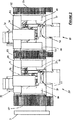
図1から6は、本発明の実施例による液圧機械1を示している。液圧機械1はハウジング10に収容されている。液圧機械1は、回転軸(図示せず)を中心として液圧機械1へ、または液圧機械から回転運動を伝達するために相補的動力継手に接続される動力継手5を有する。
1 to 6 show a hydraulic machine 1 according to an embodiment of the invention. The hydraulic machine 1 is accommodated in a
図2は、ハウジング10が除去された液圧機械1を示す。液圧機械1は、5個のピストン・シリンダアセンブリ50によるバンク20の各々が径方向に配列された2本のクランクシャフト15を有する。こうしてこの実施例の液圧機械1は、10個のピストン・シリンダアセンブリ50を有する。
FIG. 2 shows the hydraulic machine 1 with the
液圧機械1は、バンク20をいかなる整数個でも有することができる。ゆえに、本発明による液圧機械1におけるピストン・シリンダアセンブリ50の総数は、バンク20あたりのピストン・シリンダアセンブリ50の数の倍数、つまりピストン・シリンダアセンブリは5個、10個、15個である。
The hydraulic machine 1 can have any integer number of
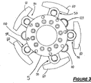
図3から5は、回転軸に沿って眺めた際の液圧機械1の図である。 3 to 5 are views of the hydraulic machine 1 when viewed along the rotation axis.
図3と4から分かるように、各バンク20の5個のピストン・シリンダアセンブリ50は回転軸を中心として等角度で配列されている。こうして、回転軸について測定すると、隣接する各ピストン・シリンダアセンブリ対50の間の角度は72°である。
As can be seen from FIGS. 3 and 4, the five piston /
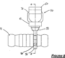
図2と6は、回転軸が紙面上にあるように液圧機械1を平面図で示す。各ピストン・シリンダアセンブリ50は、接続ロッド55によって各々のクランクシャフト15に直接装着されている。各ピストン・シリンダアセンブリ50に接続ロッド55が設けられているので、各バンク20のピストン・シリンダアセンブリ50は、回転軸に対して長手方向にオフセットしている。したがって、各バンク20の接続ロッド55は、各々のクランクシャフト15上において並置状態で配列されている。
2 and 6 show the hydraulic machine 1 in plan view with the axis of rotation on the paper . Each piston /
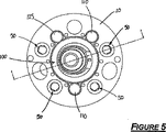
図5は、図1のB‐B線から見た液圧機械1の断面図を示す。ゆえに図5は、液圧機械1のバンク20の端面図を示す。
FIG. 5 shows a sectional view of the hydraulic machine 1 as seen from the line BB in FIG. FIG. 5 therefore shows an end view of the
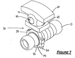
図7から11は、ピストン・シリンダアセンブリ50とクランクシャフト15の様々な図を示す。ピストン・シリンダアセンブリ50は、バンク20の5個のピストン・シリンダアセンブリのうちの1個である。
FIGS. 7 to 11 show various views of the piston and
各ピストン・シリンダアセンブリ50は、外側のスラストブロック60と内側のスラストブロック65によって支持されている。スラストブロック60,65はハウジング10に装着されている。各ピストン・シリンダアセンブリ50のシリンダヘッド70は球形を持つ。スラストブロック60,65はシリンダヘッド70を位置決めするが、クランクシャフト15の位置が変化する際にはシリンダヘッド70を往復動させる。
Each piston and
接続ロッド55とロッドキャップ56との間には、球面ベアリング75が保持されている。球面ベアリング75はクランクシャフト15を囲繞し、接続ロッド55に対するクランクシャフト15の自由相対回転運動を付与する。ロッドキャップ56は、2本の大型エンドボルト80により接続ロッド55に装着されている。
A
この構成により、各ピストン・シリンダアセンブリ50のピストン85は、接続ロッド55とロッドキャップ56との構成によってクランクシャフト15に確実に装着される。こうして、液圧モータの速度範囲は、作動液の流動特性のみによって制限される。
With this configuration, the piston 85 of each piston /
作動液は、2個の流体ポート95を介してシリンダヘッド70に対して供給および排出される。
The hydraulic fluid is supplied to and discharged from the
図10は、ピストン・シリンダアセンブリ50の断面を示す。ピストン85は接続ロッド55に直接装着されている。
FIG. 10 shows a cross section of the piston and
シリンダボアが狭すぎるので、大きな力を処理するのに充分な断面積を持つガジオンピンをシリンダ内に配置することはできない。ゆえに、接続ロッド55により必要とされる角運動を行うため、シリンダヘッド70は球形に設計されている。
Since the cylinder bore is too narrow, a gadion pin with a sufficient cross-sectional area to handle large forces cannot be placed in the cylinder. Therefore, in order to perform the angular motion required by the connecting
シリンダヘッド70は、外側および内側のスラストブロック60,65の間に保持されている。スラストブロック60,65の表面62,67は、シリンダヘッド70の球形を補完するように凹状である。クランクシャフト15の長手軸に対して平行な軸を中心に、シリンダヘッド70は自由に往復する。
図11は、図9のB‐B線におけるクランクシャフト15とピストン・シリンダアセンブリ50の断面を示す。作動液は、流体ポート95を介してピストン・シリンダアセンブリ50へ導入されるとともにピストン・シリンダアセンブリから排出される。
11 shows a cross section of the
図12は、動力継手5と一対のクランクアセンブリ25とを示す。各バンク20について1個のクランクアセンブリ25が設けられている。各バンク20には、一対のストローク調整機構100も設けられている。一対のストローク調整機構100は、各々のクランクシャフト15の行程を調整するように協働する。クランクシャフト15の行程を調整することにより、液圧機械の排出量は可変となる。言い換えると、シリンダアセンブリ50のストローク長を変化させることにより、行程容積を増減することができるのである。ゆえに、液圧機械1は速度範囲全体にわたって、無段比伝達を行う。
FIG. 12 shows the
2個のメインベアリング105(クランクシャフト15の各端部に1個)は、ストローク調整機構100を含む。その結果、トルクを伝達するのにメインベアリング105は使用できない。
Two main bearings 105 (one at each end of the crankshaft 15) include a
(液圧機械1の動作モードに応じて)出力または入力トルクを伝達するには、各メインベアリング105でトルクを集める必要がある。これは、レイシャフト110(図13参照)を用いて実施される。好適な実施例では、2本のレイシャフト110が使用される。
In order to transmit the output or input torque (depending on the operation mode of the hydraulic machine 1), it is necessary to collect the torque at each
レイシャフト110は、メインベアリング105の各々に装着されたブルギヤ120と各々が嵌合するピニオンギヤ115を有する。レイシャフト110は、ブルギヤ120からのトルクを集め、また、ブルギヤ120間の同期化を維持する役割を果たす。
The
ピストン85のストローク長を制御するため、ブルギヤ120にはらせんシャフト125が結合されている。らせんシャフト125はトルクの伝達には使用されないが、ブルギヤ120との同期状態に維持される。
In order to control the stroke length of the piston 85, a
ピストン・シリンダアセンブリ50の各バンク20について、らせんシャフト125にらせん130が形成され、らせんナット135が嵌着している。らせんナット135は突出部140を有する。各バンク20には、外装145も設けられている(図14参照)。各外装145は、各端部に浅いピニオンギヤ150を有する。外装145は、らせんシャフト125を囲繞する。
For each
突出部140は、外装145のスロット155と嵌合する。らせんナット135は回転の際に、らせんシャフト125上を長手方向に移動する。ゆえに、このようならせんナット135の長手方向移動によって、関連の外装145が回転する。
The protrusion 140 is fitted into the
各ピニオンギヤ150は、クランクシャフト15と同じ側で、ブルギヤ120に隣接して配置されたリングギヤ160に嵌合する。各リングギヤ160は、メインベアリング105上で回転自在である。らせんシャフト125上でらせんナット135が長手方向に移動すると、各々のバンク20の2個のリングギヤ160が回転する。この機構は、液圧機械1がいかなる速度または負荷で作動していてもリングギヤ160を回転させる手段となる。
Each
リングギヤ160は、ストローク調整機構100を駆動する。ゆえに、らせんナット135の長手方向移動によって、ストローク調整機構100を駆動する手段が得られる。
ストローク調整機構100は、図15から20に図示されている。
The
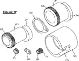
メインベアリング105は、該メインベアリング105内に偏心状態で配置された中空円筒形部分を備える円筒体である。一対の偏心リング190,205が実際のストローク変化を与える。
The
外側の偏心リング190は、中空円筒形部分を備える円筒体形状である。外側の偏心リング190の円筒体の直径は、メインベアリング105の中空部分のボアの中に回転自在に収容されるような幾何学的寸法を持つ。
Outer
外側の偏心リング190の第1端部の一部分は、一組の歯195を備える。他の端部は、釣合いおもり200を備える。
A portion of the first end portion of the outer
内側の偏心リング205は中空円筒形部分を備える円筒体形状である。内側の偏心リング205の円筒体の直径は、外側の偏心リング190の中空部分のボアの中に回転自在に支持されるような幾何学的寸法を持つ。
Inner
内側の偏心リング205の第1端部の一部分は、一組の歯210を備える。他の端部は釣合いおもり215を備える。
A portion of the first end portion of the inner
クランクシャフト15の各端部は、内側の偏心リング205の中空部分の中に保持されている。クランクシャフト15を各々のメインベアリング105に対して径方向に移動させることにより、クランクシャフト15の行程が変化する。この径方向移動は、外側の偏心リング190を第1方向に回転させるのと同時に内側の偏心リング205を反対方向に回転させることにより実施される。偏心リング190,205の回転速度は同じである。
Each end of the
各リングギヤ160の内面には、一組の歯165が形成されている。歯165は、ギヤトレーン170の第1一次ギヤ175の歯と嵌合する。第1一次ギヤ175は、外側の偏心リング190の歯195と嵌合する。
A set of teeth 165 is formed on the inner surface of each
第2一次ギヤ180は、第1一次ギヤ175の側面に装着されている。第2一次ギヤ180は第1一次ギヤ175とともに回転する。二次ギヤ185は、第2一次ギヤ180と内側の偏心リング205の歯210との間に配置される。
The second
ギヤトレーンベアリング220は、ギヤトレーン170を所定箇所に固定する。メインベアリング105は、ギヤトレーン170が延出する切欠き部106を有する。
The gear train bearing 220 fixes the
ストローク調整機構100が回転バランスを確実に維持するように、釣合いおもり200,215は各々の偏心リング190,205とともに回転する。釣合いおもり200,215は、ゼロストローク長では相殺され、フルストロークでは協働する。ストローク調整機構100、ひいては液圧機械1は、常にバランスが保たれている。
The
図16は、メインベアリング105と外側および内側の偏心リング190,205とギヤトレーン170との稜線図を示す。釣合いおもり200,215は破線で示されている。
Figure 16 shows a ridge view of the
図17は、ストローク調整機構100の分解図である。
FIG. 17 is an exploded view of the
図18から20は、外側および内側の偏心リング190,205を示す。図18はギヤトレーン170も示す。
Figures 18 20 show the outer and inner eccentric rings 190,205. FIG. 18 also shows the
液圧機械1をモータとして作動させる時には、各バンク20の5個のピストン・シリンダアセンブリ50がクランクシャフト15へ連続的に力を加えるため、クランクシャフト15に回転運動が付与される。回転運動は、ブルギヤ120を介してレイシャフト110へ伝達される。
When the hydraulic machine 1 is operated as a motor, the five piston /
液圧機械1をポンプとして作動させる時には、動力継手5が回転する。シリンダアセンブリ50は、クランクシャフト15の回転によって駆動される。ゆえに、液圧機械1から作動液が供給される。
When the hydraulic machine 1 is operated as a pump, the
発明の範囲を逸脱することなく多くの変形が可能であることは、発明の技術分野の熟練者には理解できるだろう。 It will be appreciated by those skilled in the art that many variations are possible without departing from the scope of the invention.
以下の請求項と前掲した発明の説明においては、明白な文言または必要な含意のために文脈上、他の意味を必要とする場合を除いて、例えば「備える」のような語は、包括的な意味で、つまり記載された特徴の存在を明記するが、発明の様々な実施例における別の特徴の存在または追加を除外しないように使用される。 In the following claims and in the description of the invention set forth above, words such as “comprising” are inclusive unless the context requires other meanings for obvious language or necessary implications. It is used in such a way that it explicitly states the presence of the described feature, but does not exclude the presence or addition of another feature in various embodiments of the invention.
Claims (5)
前記内側シリンダの前記中空偏心円筒形部分内に、前記内側シリンダおよび前記クランクシャフトの長手軸が平行でオフセットするように各々のクランクシャフトが収容されており、
前記外側シリンダの前記中空偏心円筒形部分内に、前記外側シリンダおよび前記内側シリンダの長手軸が平行でオフセットするように、前記内側シリンダが収容されており、
前記メインベアリングの前記偏心中空円筒形部分内に前記外側シリンダが収容されている、
請求項1または2に記載の液圧機械。The means for changing the eccentricity of the crankshaft is provided at each end of the crankshaft and includes an inner cylinder having a hollow eccentric cylindrical portion and an outer cylinder having a hollow eccentric cylindrical portion. And a cylindrical main bearing having an eccentric hollow cylindrical portion, and simultaneously rotating the outer cylinder and the inner cylinder between the main bearing and the longitudinal axis of the crankshaft at both ends of each crankshaft. Driving means operable to change the distance,
Each crankshaft is accommodated in the hollow eccentric cylindrical portion of the inner cylinder such that the longitudinal axes of the inner cylinder and the crankshaft are parallel and offset,
The inner cylinder is housed in the hollow eccentric cylindrical portion of the outer cylinder such that the longitudinal axes of the outer cylinder and the inner cylinder are offset in parallel;
The outer cylinder is housed in the eccentric hollow cylindrical portion of the main bearing;
The hydraulic machine according to claim 1 or 2.
リングの内面および外面の両方に歯を備えるリングギヤと、
前記内側シリンダおよび前記外側シリンダの各々の端部の周囲の一組の歯と、
前記リングギヤから前記内側シリンダおよび前記外側シリンダへ回転を伝達するギヤトレーンとを含んでおり、該リングギヤが各自のメインベアリングによって支持され、該メインベアリングが有する切欠き部分を介して前記ギヤトレーンが延在し前記リングギヤと嵌合する、請求項3に記載の液圧機械。The drive means at each end of the crankshaft is
A ring gear with teeth on both the inner and outer surfaces of the ring;
A set of teeth around the end of each of the inner and outer cylinders;
A gear train that transmits rotation from the ring gear to the inner cylinder and the outer cylinder. The ring gear is supported by a main bearing of the ring gear, and the gear train extends through a notch portion of the main bearing. The hydraulic machine according to claim 3, wherein the hydraulic machine is fitted with the ring gear.
前記駆動手段がさらに、外面に形成されたらせんと、前記メインベアリングの各々にある前記歯と嵌合するピニオンギヤとを備えるらせんシャフトを含んでいて、該らせんシャフトが前記メインベアリングとともに回転するようになっており、
前記駆動手段がさらに、前記らせんシャフトの前記らせんと嵌合する内側らせんと、前記らせんシャフトに対して径方向である少なくとも1個の突出部とを備える少なくとも1個のナットを含み、
前記駆動手段がさらに、前記らせんシャフトが中に延在する少なくとも1個の中空円筒形外装を含み、該少なくとも1個の中空円筒形外装はその各端部に2個の小ピニオンギヤを有していて、各小ピニオンギヤが前記駆動手段のリングギヤと嵌合し、前記少なくとも1個の中空円筒形外装が、前記少なくとも1個の突出部が延出する少なくとも1個の長手方向スロットを有する、
請求項4に記載の液圧機械。The main bearing has teeth on the outer surface, and the ring gear is provided adjacent to the teeth of each main bearing;
The drive means further includes a helical shaft comprising a helix formed on an outer surface and a pinion gear that engages the teeth on each of the main bearings, such that the helical shaft rotates with the main bearing. And
The drive means further comprises at least one nut comprising an inner helix that mates with the helix of the helical shaft and at least one protrusion that is radial with respect to the helical shaft;
The drive means further includes at least one hollow cylindrical sheath into which the helical shaft extends, the at least one hollow cylindrical sheath having two small pinion gears at each end thereof. Each small pinion gear engages with a ring gear of the drive means, and the at least one hollow cylindrical sheath has at least one longitudinal slot from which the at least one protrusion extends.
The hydraulic machine according to claim 4.
Applications Claiming Priority (3)
| Application Number | Priority Date | Filing Date | Title |
|---|---|---|---|
| AU2003906932A AU2003906932A0 (en) | 2003-12-15 | Hydraulic motor/pump | |
| AU2003906932 | 2003-12-15 | ||
| PCT/AU2004/001765 WO2005057007A1 (en) | 2003-12-15 | 2004-12-15 | Hydraulic motor/pump |
Publications (2)
| Publication Number | Publication Date |
|---|---|
| JP2007516380A JP2007516380A (en) | 2007-06-21 |
| JP4813367B2 true JP4813367B2 (en) | 2011-11-09 |
Family
ID=34658488
Family Applications (1)
| Application Number | Title | Priority Date | Filing Date |
|---|---|---|---|
| JP2006544172A Expired - Fee Related JP4813367B2 (en) | 2003-12-15 | 2004-12-15 | Hydraulic motor / pump |
Country Status (10)
| Country | Link |
|---|---|
| US (1) | US7637202B2 (en) |
| EP (1) | EP1694962A4 (en) |
| JP (1) | JP4813367B2 (en) |
| KR (1) | KR101167141B1 (en) |
| CN (1) | CN100482939C (en) |
| AU (1) | AU2004297297B2 (en) |
| CA (1) | CA2550584C (en) |
| NZ (1) | NZ548297A (en) |
| WO (1) | WO2005057007A1 (en) |
| ZA (1) | ZA200605396B (en) |
Families Citing this family (5)
| Publication number | Priority date | Publication date | Assignee | Title |
|---|---|---|---|---|
| DE102005037206A1 (en) * | 2005-08-06 | 2007-02-15 | Mahle International Gmbh | Assembly for an internal combustion engine |
| WO2012073280A1 (en) | 2010-11-30 | 2012-06-07 | Mitsubishi Heavy Industries, Ltd. | Hydraulic pump structure for wind turbine generator or tidal current generator and method of mounting hydraulic pump |
| CN105020189B (en) * | 2015-08-12 | 2019-09-27 | 西安汇鑫传动控制有限责任公司 | A kind of multi-output shaft fluid pressure drive device |
| CN107299888B (en) * | 2016-04-15 | 2020-10-16 | 罗伯特·博世有限公司 | Hydrostatic radial piston machine |
| KR102141813B1 (en) * | 2020-06-18 | 2020-08-06 | 엠아이케이티(주) | Fluid motor |
Citations (2)
| Publication number | Priority date | Publication date | Assignee | Title |
|---|---|---|---|---|
| JPH02283867A (en) * | 1989-04-21 | 1990-11-21 | Honda Motor Co Ltd | Variable stroke crank mechanism |
| JPH05240144A (en) * | 1992-02-27 | 1993-09-17 | Honda Motor Co Ltd | Variable stroke crank mechanism |
Family Cites Families (21)
| Publication number | Priority date | Publication date | Assignee | Title |
|---|---|---|---|---|
| CH34050A (en) * | 1905-04-28 | 1906-02-28 | Sinclair G W | Device on piston pumps to change the piston stroke |
| US1227780A (en) * | 1915-12-16 | 1917-05-29 | Joseph H Rapel | Rotary engine. |
| US1974961A (en) * | 1931-03-04 | 1934-09-25 | Johnson Gerald | Variable displacement pump or motor |
| US2316115A (en) * | 1941-04-23 | 1943-04-06 | Builder Thompson Engineering A | Rotary pump or motor |
| US3081708A (en) * | 1960-08-10 | 1963-03-19 | Sargent Engineering Corp | Rotary motor or pump |
| US3174436A (en) * | 1962-11-23 | 1965-03-23 | Seeger Wanner Corp | Radial pump |
| US3610106A (en) * | 1968-04-30 | 1971-10-05 | Riccardo Cavalieri | Radial variable displacement hydraulic motor of the slow type |
| FR2296778A1 (en) * | 1975-01-03 | 1976-07-30 | Rexroth Sigma | Radial-piston pump or motor - has cylinder heads of more than hemisphere section with centres held in fixed positions |
| US4236874A (en) * | 1979-03-02 | 1980-12-02 | Westinghouse Electric Corp. | Dual capacity compressor with reversible motor and controls arrangement therefor |
| SU1002611A1 (en) | 1981-11-20 | 1983-03-07 | Харьковский Ордена Ленина Политехнический Институт Им.В.И.Ленина | Piston machine |
| DE3440543A1 (en) * | 1984-11-07 | 1986-05-22 | G. Düsterloh GmbH, 4322 Sprockhövel | FLUIDIC RADIAL PISTON MACHINE |
| IT1199304B (en) | 1986-12-10 | 1988-12-30 | Siapa Spa | FLOW RATE ADJUSTMENT DEVICE FOR VARIABLE FLOW PISTON PUMPS |
| DE3711729A1 (en) | 1987-04-07 | 1988-10-27 | Josef Smidrkal | Adjustable crankshaft which makes it possible to perform continuous adjustment of the stroke of piston machines during operation |
| US4887560A (en) | 1988-06-20 | 1989-12-19 | Heniges William B | Crankshaft assembly for variable stroke engine for variable compression |
| DE3936649A1 (en) * | 1989-11-03 | 1991-05-08 | Ingelheim Peter Graf Von | Crankshaft giving adjustable stroke - has drive to adjusting components from one end via components rotating with it |
| EP0536267B1 (en) | 1990-06-29 | 1998-09-16 | Whitemoss Inc. | Adjustable rotor for a radial piston fluid machine |
| SU1825399A3 (en) | 1991-04-02 | 1993-06-30 | Kpaуиhьш Пetp Яhobич | Radial-piston hydraulic motor |
| US5368448A (en) * | 1992-02-27 | 1994-11-29 | Honda Giken Kogyo Kabushiki Kaisha | Variable-stroke crank mechanism |
| JP2576839B2 (en) * | 1993-08-07 | 1997-01-29 | プロミネント ドジーアテヒニーク ゲゼルシャフト ミット ベシュレンクター ハフツング | Stroke adjusting device for reciprocating pump |
| JPH11190326A (en) | 1997-12-25 | 1999-07-13 | Tm Japan:Kk | Variable crank stroke mechanism |
| US6840151B1 (en) * | 2003-04-10 | 2005-01-11 | Powerverde, Llc | Motor |
-
2004
- 2004-12-15 JP JP2006544172A patent/JP4813367B2/en not_active Expired - Fee Related
- 2004-12-15 KR KR1020067014263A patent/KR101167141B1/en not_active IP Right Cessation
- 2004-12-15 NZ NZ548297A patent/NZ548297A/en not_active IP Right Cessation
- 2004-12-15 AU AU2004297297A patent/AU2004297297B2/en not_active Ceased
- 2004-12-15 CA CA2550584A patent/CA2550584C/en not_active Expired - Fee Related
- 2004-12-15 EP EP04802067A patent/EP1694962A4/en not_active Withdrawn
- 2004-12-15 CN CNB2004800414834A patent/CN100482939C/en not_active Expired - Fee Related
- 2004-12-15 US US10/582,961 patent/US7637202B2/en not_active Expired - Fee Related
- 2004-12-15 WO PCT/AU2004/001765 patent/WO2005057007A1/en active Application Filing
-
2006
- 2006-06-29 ZA ZA200605396A patent/ZA200605396B/en unknown
Patent Citations (2)
| Publication number | Priority date | Publication date | Assignee | Title |
|---|---|---|---|---|
| JPH02283867A (en) * | 1989-04-21 | 1990-11-21 | Honda Motor Co Ltd | Variable stroke crank mechanism |
| JPH05240144A (en) * | 1992-02-27 | 1993-09-17 | Honda Motor Co Ltd | Variable stroke crank mechanism |
Also Published As
| Publication number | Publication date |
|---|---|
| US7637202B2 (en) | 2009-12-29 |
| NZ548297A (en) | 2010-07-30 |
| ZA200605396B (en) | 2008-05-28 |
| KR20070033318A (en) | 2007-03-26 |
| CN100482939C (en) | 2009-04-29 |
| KR101167141B1 (en) | 2012-07-20 |
| CA2550584C (en) | 2012-08-21 |
| AU2004297297A1 (en) | 2005-06-23 |
| US20070151443A1 (en) | 2007-07-05 |
| EP1694962A1 (en) | 2006-08-30 |
| AU2004297297B2 (en) | 2011-04-14 |
| CN1914418A (en) | 2007-02-14 |
| WO2005057007A1 (en) | 2005-06-23 |
| EP1694962A4 (en) | 2012-01-18 |
| CA2550584A1 (en) | 2005-06-23 |
| JP2007516380A (en) | 2007-06-21 |
Similar Documents
| Publication | Publication Date | Title |
|---|---|---|
| US5304043A (en) | Multiple axis rotary compressor | |
| US4297086A (en) | Fluid motor-pump unit | |
| US5079994A (en) | Radial piston machine | |
| JP4813367B2 (en) | Hydraulic motor / pump | |
| US6698199B2 (en) | Swash plate type hydraulic drive transmission and hydrostatic type continuously variable transmission | |
| US3981645A (en) | Displaced piston machine | |
| US5542308A (en) | Crank mechanism and machines, especially engines, using same | |
| KR20170063386A (en) | A hydraulic machine with floating cylinders | |
| US20210079955A1 (en) | Spherical device provided with convex splines for forming a ball-and-socket joint having a finger, and wobble pump provided with such a device | |
| US4132118A (en) | Piston power generating and working machine | |
| RU2698867C1 (en) | Piston machine | |
| RU2612230C1 (en) | Volume rotary-vane machines (two versions) | |
| KR100433392B1 (en) | Swash plate type axial piston apparatus | |
| JP3079230B2 (en) | Swash plate type hydraulic device | |
| RU217475U1 (en) | Axial piston hydraulic machine | |
| JPH1037848A (en) | Axial piston type hydraulic device | |
| US10273946B2 (en) | Rotary fluid device with bent cylinder sleeves | |
| RU2177063C2 (en) | Rotary machine | |
| UA64807C2 (en) | Hydraulic power transmission | |
| JPH10288149A (en) | Reciprocating type hydraulic unit and hydraulic type continuously variable transmission | |
| JPH0337464A (en) | Hydraulic continuously variable transmission | |
| GB190807478A (en) | Improvements in Pumps and Fluid Actuated Motors. | |
| MXPA96005985A (en) | Hydrostatic transmission continuously variable that has blocks of cylinders mounted in a motorcycle | |
| WO1999041499A1 (en) | A hydraulic rotating axial piston engine | |
| KR20060005021A (en) | Hydraulic pump |
Legal Events
| Date | Code | Title | Description |
|---|---|---|---|
| A621 | Written request for application examination |
Free format text: JAPANESE INTERMEDIATE CODE: A621 Effective date: 20070712 |
|
| A131 | Notification of reasons for refusal |
Free format text: JAPANESE INTERMEDIATE CODE: A131 Effective date: 20100302 |
|
| A601 | Written request for extension of time |
Free format text: JAPANESE INTERMEDIATE CODE: A601 Effective date: 20100601 |
|
| A602 | Written permission of extension of time |
Free format text: JAPANESE INTERMEDIATE CODE: A602 Effective date: 20100608 |
|
| A601 | Written request for extension of time |
Free format text: JAPANESE INTERMEDIATE CODE: A601 Effective date: 20100701 |
|
| A602 | Written permission of extension of time |
Free format text: JAPANESE INTERMEDIATE CODE: A602 Effective date: 20100708 |
|
| A601 | Written request for extension of time |
Free format text: JAPANESE INTERMEDIATE CODE: A601 Effective date: 20100730 |
|
| A602 | Written permission of extension of time |
Free format text: JAPANESE INTERMEDIATE CODE: A602 Effective date: 20100806 |
|
| RD04 | Notification of resignation of power of attorney |
Free format text: JAPANESE INTERMEDIATE CODE: A7424 Effective date: 20101008 |
|
| A02 | Decision of refusal |
Free format text: JAPANESE INTERMEDIATE CODE: A02 Effective date: 20101026 |
|
| A521 | Request for written amendment filed |
Free format text: JAPANESE INTERMEDIATE CODE: A523 Effective date: 20110228 |
|
| A911 | Transfer to examiner for re-examination before appeal (zenchi) |
Free format text: JAPANESE INTERMEDIATE CODE: A911 Effective date: 20110510 |
|
| A131 | Notification of reasons for refusal |
Free format text: JAPANESE INTERMEDIATE CODE: A131 Effective date: 20110628 |
|
| A521 | Request for written amendment filed |
Free format text: JAPANESE INTERMEDIATE CODE: A523 Effective date: 20110708 |
|
| TRDD | Decision of grant or rejection written | ||
| A01 | Written decision to grant a patent or to grant a registration (utility model) |
Free format text: JAPANESE INTERMEDIATE CODE: A01 Effective date: 20110802 |
|
| A01 | Written decision to grant a patent or to grant a registration (utility model) |
Free format text: JAPANESE INTERMEDIATE CODE: A01 |
|
| A61 | First payment of annual fees (during grant procedure) |
Free format text: JAPANESE INTERMEDIATE CODE: A61 Effective date: 20110824 |
|
| R150 | Certificate of patent or registration of utility model |
Free format text: JAPANESE INTERMEDIATE CODE: R150 |
|
| FPAY | Renewal fee payment (event date is renewal date of database) |
Free format text: PAYMENT UNTIL: 20140902 Year of fee payment: 3 |
|
| LAPS | Cancellation because of no payment of annual fees |