JP6489137B2 - Front body structure of the vehicle - Google Patents
Front body structure of the vehicle Download PDFInfo
- Publication number
- JP6489137B2 JP6489137B2 JP2017032913A JP2017032913A JP6489137B2 JP 6489137 B2 JP6489137 B2 JP 6489137B2 JP 2017032913 A JP2017032913 A JP 2017032913A JP 2017032913 A JP2017032913 A JP 2017032913A JP 6489137 B2 JP6489137 B2 JP 6489137B2
- Authority
- JP
- Japan
- Prior art keywords
- vehicle
- rain
- surface portion
- apron
- apron member
- Prior art date
- Legal status (The legal status is an assumption and is not a legal conclusion. Google has not performed a legal analysis and makes no representation as to the accuracy of the status listed.)
- Expired - Fee Related
Links
Images


Landscapes
- Body Structure For Vehicles (AREA)
Description
この発明は、車両の前後方向に延びる左右一対のエプロンメンバと、上記左右一対のエプロンメンバの前端部に結合されるシュラウドメンバとを備えた車両の前部車体構造に関する。 The present invention relates to a vehicle front body structure including a pair of left and right apron members extending in the front-rear direction of a vehicle and a shroud member coupled to a front end portion of the pair of left and right apron members.
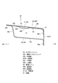
従来、上述例の車両の前部車体構造としては、図8に示すような構造が知られている。
すなわち、同図に示すように、ヒンジピラー91の上部から車両の前後方向に延びる左右一対のエプロンメンバ92,92を設けると共に、これら左右一対のエプロンメンバ92の前端部に結合部93にて結合された左右一対のシュラウドメンバ94,94を設け、さらに、これら一対のシュラウドメンバ94,94を、ラジエータシュラウド95のアッパメンバ96にて車幅方向に連結したものである。
Conventionally, a structure as shown in FIG. 8 is known as the front body structure of the vehicle in the above example.
That is, as shown in the figure, a pair of left and
上述の前部車体構造を備えた車両において、当該車両の前部左側に衝突物が低速で矢印c方向から衝突した場合、車両左側のシュラウドメンバ94が後方に押され、これにより車両右側では、シュラウドメンバ94がエプロンメンバ92と締結されている結合部93に対して、右側のシュラウドメンバ94が矢印aで示すように後退する方向の荷重(後退荷重)が入力する。車両左側だけに軽衝突荷重が入力されているので、車両右側においては図8に矢印bで示す回転力が同時に作用することになる。
上述の結合部93が補強されていない場合には、結合部93の後部に応力が集中して、エプロンメンバ92外板面が凹むような変形が生ずる。
In the vehicle having the front body structure described above, when a colliding object collides with the left side of the front portion of the vehicle from the direction of the arrow c at a low speed, the
When the above-described
このような変形を防止するためには、上述のエプロンメンバ92の結合部93近傍からヒンジピラー91近傍にかけて車両前後方向に比較的長いレインフォースメントを設け、このレインフォースメントによりエプロンメンバ92を補強することが考えられるが、上述のレインフォースメントの後部において、該レインフォースメントで補強された部位と、補強されていない部位との剛性差により、剛性差が低い部分が回転の軸となって、当該剛性差が低い部分が変形することで、エプロンメンバ92が回転変形するため、斯る回転変形を抑制する観点で改善の余地があった。
In order to prevent such deformation, a relatively long reinforcement is provided in the vehicle longitudinal direction from the vicinity of the
ところで、特許文献1には、シュラウドメンバとエプロンメンバとの結合部を補強した構造が開示されているが、この特許文献1においても、車両前部の一方側に対する軽衝突荷重の入力時には、車両他方側のエプロンメンバが回転変形することになり、この点で改善の余地があった。
By the way,
そこで、本発明は、軽衝突時のエプロンメンバにおけるシュラウドメンバとの結合部の変形を抑制すると共に、エプロンメンバ上面部の変形を抑制することができる車両の前部車体構造の提供を目的とする。 SUMMARY OF THE INVENTION Accordingly, an object of the present invention is to provide a front vehicle body structure of a vehicle that can suppress deformation of a joint portion of an apron member with a shroud member at the time of a light collision and can suppress deformation of an upper surface portion of an apron member. .
この発明による車両の前部車体構造は、車両の前後方向に延びる左右一対のエプロンメンバと、上記左右一対のエプロンメンバの前端部に結合されるシュラウドメンバとを備えた車両の前部車体構造であって、上記エプロンメンバは、略水平に延びる上面部を含む車両正面視閉断面を備え、上記エプロンメンバには、上記上面部かつ上記閉断面の内部に上記エプロンメンバ前端から車両後方に延びる前側レインが設けられ、上記前側レインの後方かつ車幅方向外側に車両前後方向に延びる後側レインが設けられ、上記前側レインの後部と上記後側レインの前部とが車両側面視でオーバラップして設けられたものである。 A vehicle front body structure according to the present invention is a vehicle front body structure including a pair of left and right apron members extending in the front-rear direction of the vehicle, and a shroud member coupled to a front end portion of the pair of left and right apron members. The apron member includes a vehicle front closed section including a top surface extending substantially horizontally, and the apron member includes a front side extending from the front end of the apron member toward the rear of the vehicle inside the top surface and the closed section. A rain is provided, a rear rain extending in the vehicle front-rear direction is provided behind the front rain and outside in the vehicle width direction, and the rear portion of the front rain and the front portion of the rear rain overlap in a side view of the vehicle. It is provided.
上記構成によれば、軽衝突時にシュラウドメンバから入力される後退荷重を、前側レインが車両後方に伝達することで、エプロンメンバにおけるシュラウドメンバとの結合部の変形を抑制することができ、また、軽衝突時に上記結合部を車幅方向内側に引込むモーメント荷重が入力される際、該モーメントの回転軸となりうる部位としての前側レインの車両後方かつ車幅方向外側を、当該前側レインとオーバラップ構造の後側レインにて補強することで、エプロンメンバの上面部に剛性差が生じないため、該上面部の変形を抑制することができる。 According to the above configuration, the rearward load input from the shroud member at the time of a light collision can be transmitted to the rear of the vehicle by the front rain, so that deformation of the joint portion of the apron member with the shroud member can be suppressed. When a moment load that pulls the connecting portion inward in the vehicle width direction during a light collision is input, the front rain as a portion that can become a rotation axis of the moment is arranged behind the vehicle in the vehicle width direction and the vehicle width direction outside. By reinforcing with the rear rain, there is no difference in rigidity in the upper surface portion of the apron member, so that deformation of the upper surface portion can be suppressed.
この発明の一実施態様においては、上記エプロンメンバは、上記上面部の下方に対向する下面部と、上記上面部と上記下面部の車幅方向内側端部を連結する内面部と、上記上面部と上記下面部の車幅方向外側端部を連結する外面部とを備えると共に、上記上面部と上記内面部とが交わる稜線部を備え、上記前側レインは上記上面部と上記内面部とに跨って設けられたものである。 In one embodiment of the present invention, the apron member includes a lower surface portion facing below the upper surface portion, an inner surface portion connecting the upper surface portion and the inner end portion in the vehicle width direction of the lower surface portion, and the upper surface portion. And an outer surface portion connecting the outer end portion in the vehicle width direction of the lower surface portion, and a ridge line portion where the upper surface portion and the inner surface portion intersect, and the front rain straddles the upper surface portion and the inner surface portion. It is provided.
上記構成によれば、前側レインがエプロンメンバの稜線部と協働して荷重伝達経路を形成するので、軽衝突時の荷重をより一層確実に車両後方へ伝達することができる。 According to the above configuration, the front rain forms a load transmission path in cooperation with the ridge line portion of the apron member, so that the load at the time of a light collision can be more reliably transmitted to the rear of the vehicle.
この発明の一実施態様においては、上記前側レインは上記上面部から下方に延びる縦壁部と、該縦壁部の下端から上記内面部へと延びる底面部とを備え、上記前側レインは上記上面部および上記内面部と協働して車両正面視で閉断面を形成し、上記前側レインの該閉断面は、少なくとも上記エプロンメンバの上記シュラウドメンバとの結合位置に形成されたものである。 In one embodiment of the present invention, the front rain includes a vertical wall portion extending downward from the upper surface portion, and a bottom surface portion extending from a lower end of the vertical wall portion to the inner surface portion, and the front rain is the upper surface. The closed section of the front rain is formed at least at a position where the apron member is coupled to the shroud member in cooperation with the inner portion and the inner surface portion.
上記構成によれば、前側レインとエプロンメンバの上面部、内面部とによる閉断面を、上記結合位置に形成したので、エプロンメンバの剛性が向上し、軽衝突時のエプロンメンバ上面部のシュラウドメンバとの結合部の変形を抑制することができる。
特に、軽衝突時において上記結合部が凹もうとする変形は、曲げ変形であるが、上記閉断面により、この曲げ変形に対する耐力の向上を図ることができる。
According to the above configuration, since the closed cross section formed by the front rain and the upper surface portion and the inner surface portion of the apron member is formed at the coupling position, the rigidity of the apron member is improved and the shroud member of the upper surface portion of the apron member at the time of a light collision is improved. The deformation of the connecting portion can be suppressed.
In particular, the deformation that the coupling portion tries to dent at the time of a light collision is a bending deformation, but the closed cross section can improve the resistance to the bending deformation.
この発明の一実施態様においては、上記エプロンメンバの後端部から車両後方に延びる後部エプロンメンバが設けられ、上記後側レインは上記エプロンメンバと該後部エプロンメンバとに跨って設けられ、上記後部エプロンメンバは上記エプロンメンバに対して強度が高く設定されたものである。 In one embodiment of the present invention, a rear apron member extending from the rear end portion of the apron member to the rear of the vehicle is provided, and the rear rain is provided across the apron member and the rear apron member, and the rear portion The apron member has a higher strength than the apron member.
上記構成によれば、軽衝突荷重が前側レインから後側レインに入力される際、後側レインは高強度の後部エプロンメンバに荷重を伝達分散することができ、エプロンメンバ上面部の変形を抑制することができると共に、該エプロンメンバのモーメントによる回転変形を抑制することができる。 According to the above configuration, when a light collision load is input from the front rain to the rear rain, the rear rain can transmit and distribute the load to the high-strength rear apron member and suppress deformation of the apron member upper surface portion. In addition, the rotational deformation due to the moment of the apron member can be suppressed.
この発明によれば、軽衝突時のエプロンメンバにおけるシュラウドメンバとの結合部の変形を抑制すると共に、エプロンメンバ上面部の変形を抑制することができる効果がある。 According to the present invention, it is possible to suppress the deformation of the joint portion of the apron member with the shroud member at the time of a light collision and to suppress the deformation of the apron member upper surface portion.
軽衝突時のエプロンメンバにおけるシュラウドメンバとの結合部の変形を抑制すると共に、エプロンメンバ上面部の変形を抑制するという目的を、車両の前後方向に延びる左右一対のエプロンメンバと、上記左右一対のエプロンメンバの前端部に結合されるシュラウドメンバとを備えた車両の前部車体構造であって、上記エプロンメンバは、略水平に延びる上面部を含む車両正面視閉断面を備え、上記エプロンメンバには、上記上面部かつ上記閉断面の内部に上記エプロンメンバ前端から車両後方に延びる前側レインが設けられ、上記前側レインの後方かつ車幅方向外側に車両前後方向に延びる後側レインが設けられ、上記前側レインの後部と上記後側レインの前部とが車両側面視でオーバラップして設けられるという構成で実現した。 A pair of left and right apron members extending in the front-rear direction of the vehicle, and the pair of left and right apron members for the purpose of suppressing deformation of the joint portion of the apron member with the shroud member at the time of a light collision and suppressing deformation of the upper surface portion of the apron member. A front body structure of a vehicle including a shroud member coupled to a front end portion of an apron member, wherein the apron member has a vehicle front-view closed cross section including an upper surface portion extending substantially horizontally, and the apron member Is provided with a front rain extending from the front end of the apron member to the rear of the vehicle inside the upper surface portion and the closed cross section, and a rear rain extending in the vehicle front-rear direction behind the front rain and outside in the vehicle width direction. The rear portion of the front rain and the front portion of the rear rain are provided so as to overlap each other when viewed from the side of the vehicle.
この発明の一実施例を以下図面に基づいて詳述する。
図面は車両の前部車体構造を示し、図1は当該前部車体構造を示す斜視図である。
An embodiment of the present invention will be described in detail with reference to the drawings.
The drawing shows the front body structure of the vehicle, and FIG. 1 is a perspective view showing the front body structure.
図1において、車両の前後方向に延びるサイドシル部1を設け、このサイドシル部1の前端部には、当該前端部から上方に立上がるヒンジピラー2を設けている。また、該ヒンジピラー2の上端から後方かつ上方に傾斜状に延びる左右一対のフロントピラー部3,3を設け、これら左右のフロントピラー部3,3の上端部相互間を、車幅方向に延びるフロントヘッダ4で連結している。
In FIG. 1, a
上述のサイドシル部1の前後方向中間と、図示しないルーフサイドレールの前後方向中間とを上下方向に連結する左右一対のセンタピラー5を設け、上述のサイドシル部1とヒンジピラー2とフロントピラー部3とルーフサイドレールとセンタピラー5とで囲繞された左右のドア開口部6,6を形成している。
A pair of left and
一方、エンジンルームと車室とを車両前後方向に仕切るダッシュロアパネル7を設け、該ダッシュロアパネル7の上端部には、車幅方向に延びるダッシュアッパパネル8を取付けて、左右のフロントピラー部3,3とフロントヘッダ4とダッシュアッパパネル8とで囲繞されたフロントウインド配設用の開口部9を形成している。
On the other hand, a dash
上述のエンジンルームの左右両サイドにおいてダッシュロアパネル7から車両前方に延びる左右一対のフロントサイドフレーム10を設け、これら各フロントサイドフレーム10の前端部にはセットプレート11を取付けている。このセットプレート11には、図示しない取付けプレートを介してクラッシュカンが取付けられる。
A pair of left and right
上述のフロントサイドフレーム10に対して上方かつ車幅方向外側の位置において、ヒンジピラー2の上部から車両前方に延びる左右一対のエプロンメンバ20(エプロンレインフォースメントと同意)を設けている。このエプロンメンバ20は、車両の前後方向に延びる車体強度部材である。
上述のエンジンルームの前部で、かつ車幅方向中央部には、アッパメンバ12、ロアメンバ13、左右のサイドメンバ14,14および2つのシュラウドアッシ部15,15を備えたラジエータシュラウド16を配設している。
A pair of left and right apron members 20 (agree with apron reinforcement) extending from the upper part of the
A
図1に示すように、左右一対のエプロンメンバ20の前端部に結合部17にて結合されるシュラウドメンバ18を設け、左右一対のシュラウドメンバ18によりラジエータシュラウド16のアッパメンバ12を連結している。つまり、ラジエータシュラウド16のアッパメンバ12は、左右一対のシュラウドメンバ18を介してエプロンメンバ20の前端部に連結されたものである。
上述のエンジンルームの後部対応位置において、上側のエプロンメンバ20と下側のフロントサイドフレーム10とを、上下方向に連結するサスペンションタワー30を設けている。
As shown in FIG. 1, a
A
このサスペンションタワー30は、サスハウジング31と、タワー部32と、ダンパ支持部を兼ねるサストップ部33とを備えている。
The
一方、図1に示すように、エプロンメンバ20の前端部と、フロントサイドフレーム10の前端部とは、連結部材19により上下方向に連結されている。なお、図1において、34はサストップ部33後部におけるエプロンメンバ20の上部かつ車幅方向内側を補強するためのカウルサイドアッパレインである。
On the other hand, as shown in FIG. 1, the front end portion of the
図2は図1の車両右側の要部拡大斜視図、図3は図2から前側のエプロンインナパネル21を取外した状態の斜視図、図4は図3の平面図である。
2 is an enlarged perspective view of the main part on the right side of the vehicle in FIG. 1, FIG. 3 is a perspective view of the front apron
図2〜図4に示すように、上述のエプロンメンバ20は、前側のエプロンインナパネル21と後側のエプロンインナパネル22とから成る正面視で逆L字状のエプロンインナパネル23(図2参照)と、前側のエプロンアウタパネル24と後側のエプロンアウタパネル25とから成る正面視で略L字状のエプロンアウタパネル26(図3参照)と、を備えている。
As shown in FIGS. 2 to 4, the
ここで、図2に示すように、前側のエプロンインナパネル21の後部と、後側のエプロンインナパネル22の前部とは連結されていて、これら両者21,22で車両の前後方向に延びるエプロンインナパネル23を構成している。
Here, as shown in FIG. 2, the rear part of the front apron
同様に、図3に示すように、前側のエプロンアウタパネル24の後部と、後側のエプロンアウタパネル25の前部とは連結されていて、これら両者24,25で車両の前後方向に延びるエプロンアウタパネル26を構成している。
Similarly, as shown in FIG. 3, the rear part of the front apron
図5は前側レインおよび後側レインを示す斜視図、図6は図4のA−A線矢視断面図、図7は図4のB−B線矢視断面図である。 5 is a perspective view showing the front rain and the rear rain, FIG. 6 is a cross-sectional view taken along line AA in FIG. 4, and FIG. 7 is a cross-sectional view taken along line BB in FIG.
図6、図7に示すように、上述のエプロンメンバ20は、略水平に延びる上面部20Uと、この上面部20Uの下方に対向する下面部20Lと、上面部20Uと下面部20Lの車幅方向内側端部を連結する内面部20INと、上面部20Uと下面部20Lの車幅方向外側端部を連結する外面部20Eとを備えると共に、これら各面部20U,20L,20IN,20Eで囲繞されて、車両前後方向に延びる車両正面視での第1閉断面S1(以下、単に閉断面S1と略記する)を備えている。
また、上述のエプロンメンバ20は、図6、図7に示すように、上面部20Uと内面部20INとが交わる稜線部X1を備えている。図2に示すように、該稜線部X1は車両の前後方向に延びている。
As shown in FIGS. 6 and 7, the
In addition, as shown in FIGS. 6 and 7, the
詳しくは、図6、図7に示すように、エプロンアウタパネル26の車幅方向内側に下面部20L内端から下方に延びるフランジ部26aを一体形成し、このフランジ部26aを内面部20INに接合固定すると共に、エプロンアウタパネル26の車幅方向外側に外面部20E上端から外方に延びるフランジ部26bを一体形成し、このフランジ部26bを上面部20Uに接合固定したものである。
Specifically, as shown in FIGS. 6 and 7, a
さらに、図2〜図4に示すように、上述の前側のエプロンインナパネル21と、前側のエプロンアウタパネル24との両者により、前部エプロンメンバ20Fを構成すると共に、上述の後側のエプロンインナパネル22と、後側のエプロンアウタパネル25との両者により、後部エプロンメンバ20Rを構成している。
Further, as shown in FIGS. 2 to 4, the front apron
上述の後部エプロンメンバ20Rは前部エプロンメンバ20Fの後端部から車両後方に延びるメンバで、この後部エプロンメンバ20Rは、当該後部エプロンメンバ20Rを構成する材料または板厚により、前部エプロンメンバ20Fに対して強度が高く設定されると共に、該後部エプロンメンバ20Rには上述のサスペンションタワー30を取付けることで、当該後部エプロンメンバ20Rの支持剛性が、前部エプロンメンバ20Fの支持剛性に対して高く設定されている。
The
図3、図4、図6、図7に示すように、エプロンメンバ20における前部エプロンメンバ20Fには、上面部20Uかつ上述の閉断面S1の内部に前部エプロンメンバ20Fの前端から車両後方に延びる前側レイン40が設けられている。この実施例では、図6、図7に示すように、該前側レイン40はエプロンメンバ20の上面部20Uと内面部20INとに跨って設けられている。
As shown in FIGS. 3, 4, 6, and 7, the
しかも、図3、図4に示すように、前側レイン40の後方で、かつ車幅方向外側には、車両前後方向に延びる後側レイン50が設けられ、前側レイン40の後部と後側レイン50の前部とが車両側面視でオーバラップして設けられている。上述の後側レイン50はエプロンメンバ20の上面部20Uの内側に接合固定されたものである。
Moreover, as shown in FIGS. 3 and 4, a
これにより、車両の前部左側に衝突物が低速で衝突する軽衝突時には、車両左側のシュラウドメンバ18が後方に押され、車両右側では、シュラウドメンバ18がエプロンメンバ20と締結されている結合部17に対して、右側のシュラウドメンバ18が後退する方向の荷重(後退荷重)が入力するが、この後退荷重を、前側レイン40が車両後方に伝達し、エプロンメンバ20におけるシュラウドメンバ18との結合部17の変形を抑制し、また上述の軽衝突時に結合部17を車幅方向内側に引込むモーメント荷重が入力される際、該モーメントの回転軸となりうる部位としての前側レイン40の車両後方かつ車幅方向外側を、前側レイン40とオーバラップさせた後側レイン50により補強し、エプロンメンバ20の上面部20Uに剛性差が生じないように成して、当該上面部20Uの変形を抑制すべく構成したものである。
Thereby, at the time of a light collision in which a collision object collides with the front left side of the vehicle at a low speed, the
また、図6、図7に示すように、上述の前側レイン40が、稜線部X1を介して連続する上面部20Uと内面部20INとに跨って設けられていることで、該前側レイン40がエプロンメンバ20の稜線部X1と協働して荷重伝達経路を形成し、これにより軽衝突時の荷重をより一層確実に車両後方へ伝達するよう構成したものである。
As shown in FIGS. 6 and 7, the
さらに、図6、図7に示すように、上述の前側レイン40は、エプロンメンバ20の上面部20Uから下方に延びる縦壁部40Hと、この縦壁部40Hの下端から内面部20INへと延びる底面部40Bとを備えている。
Further, as shown in FIGS. 6 and 7, the
前側レイン40は、上述の縦壁部40Hの上端部から車幅方向外側に延びるフランジ部40aと、上述の底面部40Bの車幅方向内端部から下方に延びるフランジ部40bと、を備えており、一方のフランジ部40aをエプロンメンバ20の上面部20Uに接合固定し、他方のフランジ部40bをエプロンメンバ20の内面部20INに接合固定することで、該前側レイン40が、図6、図7に示すように、上面部20Uおよび内面部20INと協働して車両正面視で第2閉断面S2(以下、単に閉断面S2と略記する)を形成している。
The
そして、上述の前側レイン40の閉断面S2は、エプロンメンバ20のシュラウドメンバ18との結合位置(結合部17参照)を含んで車両前後方向に延びるように形成されている。この実施例では、当該閉断面S2は前側レイン40におけるフランジ部40aの前後方向長さと対応する範囲に形成されている。
The closed section S2 of the
このように、前側レイン40とエプロンメンバ20の上面部20U、内面部20INとによる上記閉断面S2を、少なくとも結合部17が位置するシュラウドメンバ18との結合位置に形成することで、閉断面S1と閉断面S2との2重閉断面構造により、エプロンメンバ20の剛性が向上し、上述の軽衝突時におけるエプロンメンバ20の上面部20Uのシュラウドメンバ18との結合部17の変形を抑制するよう構成したものである。
As described above, the closed cross section S2 formed by the
さらに、図3、図4に示すように、上述の後側レイン50は、前部エプロンメンバ20Fと、該前部エプロンメンバ20Fに対して高強度の後部エプロンメンバ20Rとに跨って設けられており、これにより、軽衝突荷重が前側レイン40から後側レイン50に入力される際、後側レイン50は高強度の後部エプロンメンバ20Rに荷重を伝達分散して、エプロンメンバ20の上面部20Uの変形を抑制すると共に、該エプロンメンバ20のモーメントによる回転変形を抑制するよう構成したものである。
なお、図中、矢印Fは車両前方を示し、矢印Rは車両後方を示し、矢印INは車幅方向の内方を示し、矢印OUTは車幅方向の外方を示し、矢印UPは車両上方を示す。
Further, as shown in FIGS. 3 and 4, the
In the figure, arrow F indicates the front of the vehicle, arrow R indicates the rear of the vehicle, arrow IN indicates the inward in the vehicle width direction, arrow OUT indicates the outward in the vehicle width direction, and arrow UP indicates the upper side of the vehicle. Indicates.
このように、上記実施例の車両の前部車体構造は、車両の前後方向に延びる左右一対のエプロンメンバ20,20と、上記左右一対のエプロンメンバ20,20の前端部に結合されるシュラウドメンバ18とを備えた車両の前部車体構造であって、上記エプロンメンバ20は、略水平に延びる上面部20Uを含む車両正面視閉断面S1を備え、上記エプロンメンバ20には、上記上面部20Uかつ上記閉断面S1の内部に上記エプロンメンバ20前端から車両後方に延びる前側レイン40が設けられ、上記前側レイン40の後方かつ車幅方向外側に車両前後方向に延びる後側レイン50が設けられ、上記前側レイン40の後部と上記後側レイン50の前部とが車両側面視でオーバラップして設けられたものである(図1、図3、図6、図7参照)。
As described above, the front body structure of the vehicle according to the embodiment includes the pair of left and
この構成によれば、軽衝突時にシュラウドメンバ18から入力される後退荷重を、前側レイン40が車両後方に伝達することで、エプロンメンバ20におけるシュラウドメンバ18との結合部17の変形を抑制することができ、また、軽衝突時に上記結合部17を車幅方向内側に引込むモーメント荷重が入力される際、該モーメントの回転軸となりうる部位としての前側レイン40の車両後方かつ車幅方向外側を、当該前側レイン40とオーバラップ構造の後側レイン50にて補強することで、エプロンメンバ20の上面部20Uに剛性差が生じないため、該上面部20Uの変形を抑制することができる。
上述の構成は、特に、車両全幅が異なる車両において、エプロンメンバ20に共通部分を用いる必要がある場合に、有効となる。
According to this configuration, the
The above-described configuration is particularly effective when a common portion needs to be used for the
この発明の一実施形態においては、上記エプロンメンバ20は、上記上面部20Uの下方に対向する下面部20Lと、上記上面部20Uと上記下面部20Lの車幅方向内側端部を連結する内面部20INと、上記上面部20Uと上記下面部20Lの車幅方向外側端部を連結する外面部20Eとを備えると共に、上記上面部20Uと上記内面部20INとが交わる稜線部X1を備え、上記前側レイン40は上記上面部20Uと上記内面部20INとに跨って設けられたものである(図6、図7参照)。
In an embodiment of the present invention, the
この構成によれば、前側レイン40がエプロンメンバ20の稜線部X1と協働して荷重伝達経路を形成するので、軽衝突時の荷重をより一層確実に車両後方へ伝達することができる。
According to this configuration, the
この発明の一実施形態においては、上記前側レイン40は上記上面部20Uから下方に延びる縦壁部40Hと、該縦壁部40Hの下端から上記内面部20INへと延びる底面部40Bとを備え、上記前側レイン40は上記上面部20Uおよび上記内面部20INと協働して車両正面視で閉断面S2を形成し、上記前側レイン40の該閉断面S2は、少なくとも上記エプロンメンバ20の上記シュラウドメンバ18との結合位置(結合部17の位置参照)に形成されたものである(図3、図4、図6参照)。
In one embodiment of the present invention, the
この構成によれば、前側レイン40とエプロンメンバ20の上面部20U、内面部20INとによる閉断面S2を、上記結合位置に形成したので、エプロンメンバ20の剛性が向上し、軽衝突時のエプロンメンバ20上面部20Uのシュラウドメンバ18との結合部17の変形を抑制することができる。
特に、軽衝突時において上記結合部17が凹もうとする変形は、曲げ変形であるが、上記閉断面S2により、この曲げ変形に対する耐力の向上を図ることができる。
According to this configuration, since the closed cross section S2 formed by the
In particular, the deformation that the
この発明の一実施形態においては、上記エプロンメンバ(前部エプロンメンバ20F参照)の後端部から車両後方に延びる後部エプロンメンバ20Rが設けられ、上記後側レイン50は上記エプロンメンバ(前部エプロンメンバ20F)と該後部エプロンメンバ20Rとに跨って設けられ、上記後部エプロンメンバ20Rは上記エプロンメンバ(前部エプロンメンバ20F)に対して強度が高く設定されたものである(図3、図4参照)。
In one embodiment of the present invention, a
この構成によれば、軽衝突荷重が前側レイン40から後側レイン50に入力される際、後側レイン50は高強度の後部エプロンメンバ20Rに荷重を伝達分散することができ、エプロンメンバ上面部(前部エプロンメンバ20Fの上面部20U)の変形を抑制することができると共に、該エプロンメンバ20のモーメントによる回転変形を抑制することができる。
According to this configuration, when a light collision load is input from the
この発明の構成と、上述の実施例との対応において、
この発明の請求項4に記載のエプロンメンバは、実施例の前部エプロンメンバ20Fに対応するも、
この発明は、上述の実施例の構成のみに限定されるものではない。
例えば、上記実施例においてはエプロンメンバ20の閉断面S1内部に前側レイン40と後側レイン50との合計2つのレインを設けたが、前側レイン、中間レイン、後側レインの合計3つのレインを設ける構造を採用してもよい。
In the correspondence between the configuration of the present invention and the above-described embodiment,
The apron member according to claim 4 of the present invention corresponds to the
The present invention is not limited to the configuration of the above-described embodiment.
For example, in the above embodiment, a total of two rains of the
以上説明したように、本発明は、車両の前後方向に延びる左右一対のエプロンメンバと、上記左右一対のエプロンメンバの前端部に結合されるシュラウドメンバとを備えた車両の前部車体構造について有用である。 As described above, the present invention is useful for a front body structure of a vehicle including a pair of left and right apron members extending in the front-rear direction of the vehicle and a shroud member coupled to a front end portion of the pair of left and right apron members. It is.
18…シュラウドメンバ
20…エプロンメンバ
20F…前部エプロンメンバ
20R…後部エプロンメンバ
20E…外面部
20IN…内面部
20L…下面部
20U…上面部
40…前側レイン
40B…底面部
40H…縦壁部
50…後側レイン
S1,S2…閉断面
X1…稜線
18 ...
Claims (4)
上記左右一対のエプロンメンバの前端部に結合されるシュラウドメンバとを備えた
車両の前部車体構造であって、
上記エプロンメンバは、略水平に延びる上面部を含む車両正面視閉断面を備え、
上記エプロンメンバには、上記上面部かつ上記閉断面の内部に上記エプロンメンバ前端から車両後方に延びる前側レインが設けられ、
上記前側レインの後方かつ車幅方向外側に車両前後方向に延びる後側レインが設けられ、
上記前側レインの後部と上記後側レインの前部とが車両側面視でオーバラップして設けられたことを特徴とする
車両の前部車体構造。 A pair of left and right apron members extending in the longitudinal direction of the vehicle;
A vehicle front body structure including a shroud member coupled to a front end portion of the pair of left and right apron members,
The apron member includes a vehicle front view closed cross section including an upper surface portion extending substantially horizontally,
The apron member is provided with a front rain extending from the front end of the apron member to the rear of the vehicle in the upper surface portion and the closed cross section.
A rear rain extending in the vehicle front-rear direction is provided behind the front rain and outside in the vehicle width direction,
A front body structure of a vehicle, wherein a rear portion of the front rain and a front portion of the rear rain are provided so as to overlap in a side view of the vehicle.
上記上面部と上記内面部とが交わる稜線部を備え、
上記前側レインは上記上面部と上記内面部とに跨って設けられた
請求項1に記載の車両の前部車体構造。 The apron member includes a lower surface facing the lower surface of the upper surface, an inner surface connecting the upper surface and the inner end in the vehicle width direction of the lower surface, and the outer surface of the upper surface and the lower surface in the vehicle width direction. And an outer surface connecting the end portions,
A ridge line portion where the upper surface portion and the inner surface portion intersect,
The front body structure of a vehicle according to claim 1, wherein the front rain is provided across the upper surface portion and the inner surface portion.
上記前側レインは上記上面部および上記内面部と協働して車両正面視で閉断面を形成し、
上記前側レインの該閉断面は、少なくとも上記エプロンメンバの上記シュラウドメンバとの結合位置に形成された
請求項2に記載の車両の前部車体構造。 The front rain includes a vertical wall portion extending downward from the upper surface portion, and a bottom surface portion extending from the lower end of the vertical wall portion to the inner surface portion,
The front rain forms a closed cross section in front view of the vehicle in cooperation with the upper surface portion and the inner surface portion,
The vehicle front body structure according to claim 2, wherein the closed cross section of the front rain is formed at a position where at least the apron member is coupled to the shroud member.
上記後側レインは上記エプロンメンバと該後部エプロンメンバとに跨って設けられ、
上記後部エプロンメンバは上記エプロンメンバに対して強度が高く設定された
請求項1〜3の何れか一項に記載の車両の前部車体構造。 A rear apron member extending rearward from the rear end of the apron member is provided;
The rear rain is provided across the apron member and the rear apron member,
The front body structure of a vehicle according to any one of claims 1 to 3, wherein the rear apron member has a higher strength than the apron member.
Priority Applications (1)
| Application Number | Priority Date | Filing Date | Title |
|---|---|---|---|
| JP2017032913A JP6489137B2 (en) | 2017-02-24 | 2017-02-24 | Front body structure of the vehicle |
Applications Claiming Priority (1)
| Application Number | Priority Date | Filing Date | Title |
|---|---|---|---|
| JP2017032913A JP6489137B2 (en) | 2017-02-24 | 2017-02-24 | Front body structure of the vehicle |
Publications (2)
| Publication Number | Publication Date |
|---|---|
| JP2018135079A JP2018135079A (en) | 2018-08-30 |
| JP6489137B2 true JP6489137B2 (en) | 2019-03-27 |
Family
ID=63365209
Family Applications (1)
| Application Number | Title | Priority Date | Filing Date |
|---|---|---|---|
| JP2017032913A Expired - Fee Related JP6489137B2 (en) | 2017-02-24 | 2017-02-24 | Front body structure of the vehicle |
Country Status (1)
| Country | Link |
|---|---|
| JP (1) | JP6489137B2 (en) |
Family Cites Families (12)
| Publication number | Priority date | Publication date | Assignee | Title |
|---|---|---|---|---|
| JPH033102Y2 (en) * | 1985-03-15 | 1991-01-28 | ||
| JPS61196182U (en) * | 1985-05-29 | 1986-12-06 | ||
| JPH054464Y2 (en) * | 1986-10-28 | 1993-02-03 | ||
| JP2530644B2 (en) * | 1987-03-18 | 1996-09-04 | マツダ株式会社 | Front body structure of automobile |
| JP2796173B2 (en) * | 1990-04-25 | 1998-09-10 | ダイハツ工業株式会社 | Vehicle side member structure |
| JP2795010B2 (en) * | 1991-10-18 | 1998-09-10 | トヨタ自動車株式会社 | Car front side member |
| JPH06286658A (en) * | 1993-03-31 | 1994-10-11 | Mazda Motor Corp | Car body structure of automobile |
| JP2001010534A (en) * | 1999-06-24 | 2001-01-16 | Nissan Motor Co Ltd | Automotive front end module structure |
| JP2008068760A (en) * | 2006-09-14 | 2008-03-27 | Nissan Motor Co Ltd | Vehicle body front structure |
| JP4728289B2 (en) * | 2007-06-19 | 2011-07-20 | 本田技研工業株式会社 | Body front structure |
| US8517461B2 (en) * | 2011-07-29 | 2013-08-27 | Nissan North America, Inc. | Vehicle body structure |
| JP5692210B2 (en) * | 2012-12-07 | 2015-04-01 | トヨタ自動車株式会社 | Body front structure |
-
2017
- 2017-02-24 JP JP2017032913A patent/JP6489137B2/en not_active Expired - Fee Related
Also Published As
| Publication number | Publication date |
|---|---|
| JP2018135079A (en) | 2018-08-30 |
Similar Documents
| Publication | Publication Date | Title |
|---|---|---|
| JP4853101B2 (en) | Front body structure of automobile | |
| JP5776560B2 (en) | Auto body front structure | |
| JP5867115B2 (en) | Lower body structure of the vehicle | |
| JP6982760B2 (en) | Vehicle front body structure | |
| JP6299486B2 (en) | Body front structure | |
| JP6079708B2 (en) | Front body structure of the vehicle | |
| EP3566931B1 (en) | Vehicle body structure, and vehicle | |
| JP6181099B2 (en) | Rear structure of the car body | |
| JP4244666B2 (en) | Front body structure of the vehicle | |
| JP5857412B2 (en) | Reinforcement structure at the front of the vehicle | |
| JP5639936B2 (en) | Body side structure | |
| JP4935330B2 (en) | Body front structure | |
| JP6172211B2 (en) | Rear body structure of the vehicle | |
| JP6579131B2 (en) | Front body structure of the vehicle | |
| JP5007575B2 (en) | Auto body structure | |
| JP6156088B2 (en) | Front body structure of the vehicle | |
| US11142251B2 (en) | Upper vehicle-body structure | |
| JP6237669B2 (en) | Upper body structure of the vehicle | |
| JP6171878B2 (en) | Front body structure of the vehicle | |
| JP5076718B2 (en) | Front body structure of automobile | |
| JP6269758B1 (en) | Front body structure of the vehicle | |
| JP6489137B2 (en) | Front body structure of the vehicle | |
| JP6221164B2 (en) | Body structure | |
| JP2009101956A (en) | Cowl structure of automobile | |
| JP4592399B2 (en) | Vehicle front pillar structure |
Legal Events
| Date | Code | Title | Description |
|---|---|---|---|
| A977 | Report on retrieval |
Free format text: JAPANESE INTERMEDIATE CODE: A971007 Effective date: 20190117 |
|
| TRDD | Decision of grant or rejection written | ||
| A01 | Written decision to grant a patent or to grant a registration (utility model) |
Free format text: JAPANESE INTERMEDIATE CODE: A01 Effective date: 20190129 |
|
| A61 | First payment of annual fees (during grant procedure) |
Free format text: JAPANESE INTERMEDIATE CODE: A61 Effective date: 20190211 |
|
| R150 | Certificate of patent or registration of utility model |
Ref document number: 6489137 Country of ref document: JP Free format text: JAPANESE INTERMEDIATE CODE: R150 |
|
| LAPS | Cancellation because of no payment of annual fees |