JP6470599B2 - Mold - Google Patents

Mold Download PDF

Info

Publication number
JP6470599B2
JP6470599B2 JP2015049471A JP2015049471A JP6470599B2 JP 6470599 B2 JP6470599 B2 JP 6470599B2 JP 2015049471 A JP2015049471 A JP 2015049471A JP 2015049471 A JP2015049471 A JP 2015049471A JP 6470599 B2 JP6470599 B2 JP 6470599B2
Authority
JP
Japan
Prior art keywords
ring
resin
cavity
plunger
flange portion
Prior art date
Legal status (The legal status is an assumption and is not a legal conclusion. Google has not performed a legal analysis and makes no representation as to the accuracy of the status listed.)
Active
Application number
JP2015049471A
Other languages
Japanese (ja)
Other versions
JP2015214140A (en
Inventor
青木 邦弘
邦弘 青木
賢司 西澤
賢司 西澤
Current Assignee (The listed assignees may be inaccurate. Google has not performed a legal analysis and makes no representation or warranty as to the accuracy of the list.)
Apic Yamada Corp
Original Assignee
Apic Yamada Corp
Priority date (The priority date is an assumption and is not a legal conclusion. Google has not performed a legal analysis and makes no representation as to the accuracy of the date listed.)
Filing date
Publication date
Application filed by Apic Yamada Corp filed Critical Apic Yamada Corp
Priority to JP2015049471A priority Critical patent/JP6470599B2/en
Publication of JP2015214140A publication Critical patent/JP2015214140A/en
Application granted granted Critical
Publication of JP6470599B2 publication Critical patent/JP6470599B2/en
Active legal-status Critical Current
Anticipated expiration legal-status Critical

Links

Images

Classifications

    • BPERFORMING OPERATIONS; TRANSPORTING
    • B29WORKING OF PLASTICS; WORKING OF SUBSTANCES IN A PLASTIC STATE IN GENERAL
    • B29CSHAPING OR JOINING OF PLASTICS; SHAPING OF MATERIAL IN A PLASTIC STATE, NOT OTHERWISE PROVIDED FOR; AFTER-TREATMENT OF THE SHAPED PRODUCTS, e.g. REPAIRING
    • B29C45/00Injection moulding, i.e. forcing the required volume of moulding material through a nozzle into a closed mould; Apparatus therefor
    • B29C45/17Component parts, details or accessories; Auxiliary operations
    • B29C45/46Means for plasticising or homogenising the moulding material or forcing it into the mould
    • B29C45/58Details
    • B29C45/586Injection or transfer plungers

Landscapes

  • Engineering & Computer Science (AREA)
  • Manufacturing & Machinery (AREA)
  • Mechanical Engineering (AREA)
  • Moulds For Moulding Plastics Or The Like (AREA)
  • Injection Moulding Of Plastics Or The Like (AREA)
  • Encapsulation Of And Coatings For Semiconductor Or Solid State Devices (AREA)

Description

本発明は、成形金型に適用して有効な技術に関する。   The present invention relates to a technique effective when applied to a molding die.

特開2004−134607号公報(以下、「特許文献1」という。)に記載のプランジャには、ヘッド部(先端部)に周溝が形成されると共に、該周溝よりもプランジャ先端の側面にテーパ部が形成されている。これによれば、樹脂封止動作により、周溝に樹脂が残って樹脂リングとなり、樹脂リングにより、プランジャ後端側に樹脂かすを流さないことができる。   In the plunger described in Japanese Patent Application Laid-Open No. 2004-134607 (hereinafter referred to as “Patent Document 1”), a circumferential groove is formed in the head portion (tip portion), and on the side surface of the plunger tip rather than the circumferential groove. A tapered portion is formed. According to this, resin remains in the circumferential groove by the resin sealing operation to form a resin ring, and the resin ring can prevent the resin debris from flowing on the plunger rear end side.

特開2007−15119号公報(以下、「特許文献2」という。)に記載のプランジャには、ポットを構成する金属よりも熱膨張係数が大きな材質(樹脂)からなるプランジャリングがヘッド部に設けられている。これによれば、プランジャリングの熱膨張によって、ポットとの隙間がなくなり、プランジャの下方に樹脂かすが落下するのを防止することができる。   The plunger described in Japanese Patent Application Laid-Open No. 2007-15119 (hereinafter referred to as “Patent Document 2”) is provided with a plunger ring made of a material (resin) having a thermal expansion coefficient larger than that of the metal constituting the pot in the head portion. It has been. According to this, the gap between the pot and the pot disappears due to the thermal expansion of the plunger ring, and the resin debris can be prevented from dropping below the plunger.

特開2003−175535号公報(以下、「特許文献3」という。)に記載のプランジャには、樹脂からなるシール用部材がヘッド部下に設けられている。このシール用部材には、ヘッド部から露出しているシール用部材の上面においてヘッド部を囲む溝が設けられ、この溝とシール用部材の外周側面との間に肉厚の小さい変形部が設けられている。これによれば、樹脂を圧送する際に溝を満たした樹脂からの圧力を受けて、シール用部材の外周側面側に撓むように変形部が変形し、シール用部材とポットとの間において隙間の発生を抑制することができる。   In the plunger described in Japanese Patent Laid-Open No. 2003-175535 (hereinafter referred to as “Patent Document 3”), a sealing member made of resin is provided below the head portion. The sealing member is provided with a groove surrounding the head portion on the upper surface of the sealing member exposed from the head portion, and a small deformation portion is provided between the groove and the outer peripheral side surface of the sealing member. It has been. According to this, when the resin is pumped, the deformed portion is deformed so as to bend toward the outer peripheral side surface of the sealing member under pressure from the resin filling the groove, and the gap between the sealing member and the pot Occurrence can be suppressed.

特開2012−166432号公報(以下、「特許文献4」という。)には、キャビティ凹部の底面に設けられたポットと、ポット内で型閉じ動作に応じて相対的に進退動(往復動)するように設けられたプランジャとを有する成形金型が記載されている。   Japanese Patent Application Laid-Open No. 2012-166432 (hereinafter referred to as “Patent Document 4”) describes a pot provided on the bottom surface of a cavity recess and a relative advance and retreat (reciprocation) in the pot according to a mold closing operation. A molding die having a plunger provided to do so is described.

特許第5174874号公報(以下、「特許文献5」という。)には、上型と、この上型に対向配置された、枠部材及びこの枠部材内で上下動可能な底面部材からなる下型とを備える圧縮成形型が記載されている。   In Japanese Patent No. 5174874 (hereinafter referred to as “Patent Document 5”), an upper mold, a lower mold comprising a frame member and a bottom member which can be moved up and down within the frame member, are arranged opposite to the upper mold. A compression mold is provided.

特開2004−134607号公報JP 2004-134607 A 特開2007−15119号公報JP 2007-15119 A 特開2003−175535号公報JP 2003-175535 A 特開2012−166432号公報JP 2012-166432 A 特許第5174874号公報Japanese Patent No. 5174874

例えば半導体チップなどの電子部品が樹脂で封止された成形品(半導体装置などの樹脂封止製品)に対して、近年、薄型化(小型化)が求められている。このため、成形品の薄型化に合わせてトランスファ成形を行う場合、小容量のキャビティ内で行われ、また、より高流動性で高密着性の樹脂が用いられるようになってきている。   For example, in recent years, thinning (miniaturization) has been demanded for molded products in which electronic components such as semiconductor chips are sealed with resin (resin-sealed products such as semiconductor devices). For this reason, when performing transfer molding in accordance with the reduction in thickness of a molded product, it is performed in a small-capacity cavity, and a resin having higher fluidity and higher adhesion has been used.

トランスファ成形において高流動性の樹脂を用いた場合、プランジャ(押圧部材)の進退動の際にポット(貫通部材)とプランジャの隙間に樹脂が漏れ易くなってしまう。その結果としてプランジャ摺動面にかじりが発生し、プランジャ作動不良が起きていた。また、その隙間に樹脂が漏れてしまうと、樹脂が硬化してプランジャの進退動抵抗(摺動抵抗)が増加してしまう。その結果として樹脂プランジャの下側に樹脂が堆積することによりプランジャの作動不良がおきてプランジャ破損やトランスファユニットの破損がおきていた。このように進退動抵抗が変化してしまうと、プランジャがキャビティ内へ樹脂を圧送する圧力に差が生じてしまい、樹脂封止した際にボイドが発生する原因となる。したがって、成形品の品質(信頼性)が低下してしまう。このため、ポットとプランジャの隙間で樹脂が漏れるのを防止することが求められる。   When a highly fluid resin is used in transfer molding, the resin is likely to leak into the gap between the pot (penetrating member) and the plunger when the plunger (pressing member) moves forward and backward. As a result, galling occurred on the plunger sliding surface, causing malfunction of the plunger. Further, if the resin leaks into the gap, the resin hardens and the advance / retreat resistance (sliding resistance) of the plunger increases. As a result, the resin is deposited on the lower side of the resin plunger, resulting in malfunction of the plunger, and damage to the plunger or transfer unit. If the forward / backward resistance changes in this way, a difference occurs in the pressure with which the plunger pumps the resin into the cavity, which causes a void when the resin is sealed. Therefore, the quality (reliability) of the molded product is deteriorated. For this reason, it is required to prevent the resin from leaking through the gap between the pot and the plunger.

また、高密着性の樹脂を用いた場合、樹脂を圧送するヘッド部の押圧面(ヘッド上面)に硬化した樹脂が張り付き易くなってしまう。ヘッド部に樹脂が張り付いてしまうと、金型から成形品を離型する際に欠けてしまい、搬送できなくなる原因となる。したがって、成形品の生産性が低下してしまう。このため、プランジャのメンテナンス性を向上させることが求められる。   In addition, when a highly adhesive resin is used, the cured resin tends to stick to the pressing surface (head upper surface) of the head portion that pumps the resin. If the resin sticks to the head part, it will be chipped when the molded product is released from the mold, and this will cause conveyance failure. Therefore, the productivity of the molded product is reduced. For this reason, it is required to improve the maintainability of the plunger.

また、圧縮成形においても、キャビティの底面に設けられるプランジャ(例えば、特許文献4参照)や底面部材(例えば、特許文献5参照)を用いる場合、これらが進退動(上下動)する押圧部材(可動部材)となるため、摺動箇所(隙間)で樹脂が漏れる(入り込む)のを防止することが求められる。   Also, in compression molding, when a plunger (for example, see Patent Document 4) or a bottom member (for example, see Patent Document 5) provided on the bottom surface of the cavity is used, a pressing member (movable) that moves forward and backward (up and down movement). Therefore, it is required to prevent the resin from leaking (entering) at the sliding portion (gap).

本発明の目的は、押圧部材の周囲で樹脂が漏れるのを防止することのできる技術を提供することにある。本発明の他の目的は、可動部材のメンテナンス性を向上させることのできる技術を提供することにある。本発明の前記ならびにその他の目的と新規な特徴は、本明細書の記述および添付図面から明らかになるであろう。   The objective of this invention is providing the technique which can prevent that resin leaks around a press member. Another object of the present invention is to provide a technique capable of improving the maintainability of a movable member. The above and other objects and novel features of the present invention will be apparent from the description of this specification and the accompanying drawings.

本願において開示される発明のうち、代表的なものの概要を簡単に説明すれば、次のとおりである。   Of the inventions disclosed in the present application, the outline of typical ones will be briefly described as follows.

本発明の一実施形態に係る成形金型は、貫通孔を有する貫通部材(ポットまたはクランパ)と、前記貫通孔に挿入され、樹脂を押圧する押圧面を有する押圧部材(プランジャまたはキャビティ駒)とを備え、前記貫通部材と前記押圧部材とが相対的に進退動可能に設けられる成形金型であって、前記押圧部材は、端部にフランジ部を有すると共に、外周側面には周溝が形成され、前記押圧部材の外周側面から突き出て前記貫通部材の内周面との隙間を塞ぐようにシールリング(プランジャリングまたはキャビティリング)が前記周溝に嵌め込まれ、前記シールリングには樹脂溜まり部となる環状溝部が形成されており、前記環状溝部は、前記フランジ部側の開口縁から前記フランジ部と逆側の開口縁に至る形状が径方向内側に向かって掘設された溝状に形成され、且つ、前記フランジ部側の開口縁が面取りされて前記フランジ部と逆側の開口縁よりも開口が所定寸法径方向内側となるように形成されており、前記フランジ部の外径寸法が前記環状溝部の前記フランジ部側の開口縁の外径寸法と同じであり、且つ、前記ヘッド本体部の周溝ではない位置の外径寸法が前記環状溝部の前記フランジ部と逆側の開口縁の外径寸法よりも小さいことを特徴とする。これによれば、樹脂溜まり部に樹脂が溜まるため押圧部材の周囲で樹脂が漏れるのを防止することができる。 A molding die according to an embodiment of the present invention includes a penetrating member (pot or clamper) having a through hole, and a pressing member (plunger or cavity piece) having a pressing surface that is inserted into the through hole and presses the resin. A molding die in which the penetrating member and the pressing member are provided so as to be relatively movable back and forth. The pressing member has a flange portion at an end portion and a circumferential groove is formed on an outer peripheral side surface. A seal ring (plunger ring or cavity ring) is fitted into the circumferential groove so as to protrude from the outer peripheral side surface of the pressing member and close the gap with the inner peripheral surface of the penetrating member. Ho設of an annular groove made is formed, the annular groove, the shape extending from the opening edge of the flange portion side opening edge of the flange portion and the opposite side is radially inward The flange portion side opening edge is chamfered so that the opening is on the inner side in the predetermined dimension radial direction with respect to the opening edge opposite to the flange portion, and the flange portion The outer diameter of the annular groove is the same as the outer diameter of the opening edge on the flange portion side of the annular groove, and the outer diameter of the position that is not the circumferential groove of the head main body is the flange of the annular groove. It is characterized by being smaller than the outer diameter of the opening edge on the opposite side . According to this, since resin accumulates in the resin reservoir portion, it is possible to prevent the resin from leaking around the pressing member.

前記一実施形態に係る成形金型において、前記樹脂溜まり部に樹脂リングが形成され、前記シールリングが拡径するように変形していることがより好ましい。このように、シールリングが拡径方向に変形したりすることで、押圧部材と貫通部材の隙間を塞いで(あるいは小さくして)、押圧部材が相対的に摺動することとなる。したがって、押圧面の周囲で樹脂が漏れるのを防止することができる。   In the molding die according to the one embodiment, it is more preferable that a resin ring is formed in the resin reservoir portion and the seal ring is deformed so as to expand its diameter. As described above, the seal ring is deformed in the diameter increasing direction, thereby closing (or reducing) the gap between the pressing member and the penetrating member, and the pressing member slides relatively. Therefore, it is possible to prevent the resin from leaking around the pressing surface.

前記一実施形態に係る成形金型において、前記押圧部材の外周側面には、前記周溝と交差するように、前記押圧面から前記樹脂溜まり部に連通する連通溝が形成されていることがより好ましい。これによれば、押圧面で樹脂を押圧する際に、連通溝を介して樹脂溜まり部に樹脂を入り込むことができる。   In the molding die according to the embodiment, a communication groove that communicates from the pressing surface to the resin reservoir portion is formed on the outer peripheral side surface of the pressing member so as to intersect the circumferential groove. preferable. According to this, when the resin is pressed by the pressing surface, the resin can enter the resin reservoir through the communication groove.

本発明の他の実施形態に係る成形金型は、貫通孔を有する貫通部材と、前記貫通孔に挿入され、樹脂を押圧する押圧面を有する押圧部材とを備え、前記貫通部材と前記押圧部材とが相対的に進退動可能に設けられる成形金型であって、前記押圧部材の外周側面には周溝が形成され、前記押圧部材の外周側面から突き出て前記貫通部材の内周面との隙間を塞ぐようにシールリングが前記周溝に嵌め込まれ、前記押圧面で樹脂を押圧する押圧力の反力によって前記シールリングが拡径方向に移動することを特徴とする。ここで、前記シールリングは、第1リングと第2リングに分割されて積層されており、前記第1リングと前記第2リングとの分割面がテーパ面に形成されていること、または、前記シールリングと前記押圧部材との当接面がテーパ面に形成されていることがより好ましい。これによれば、シールリングが拡径方向に移動し、貫通部材の内周面の隙間を塞いで(あるいは小さくして)押圧部材が摺動するので、押圧面の周囲で樹脂が漏れるのを防止することができる。   A molding die according to another embodiment of the present invention includes a penetrating member having a through hole, and a pressing member having a pressing surface that is inserted into the through hole and presses the resin, and the penetrating member and the pressing member Is a molding die provided so as to be relatively movable back and forth, and a circumferential groove is formed on the outer peripheral side surface of the pressing member, and protrudes from the outer peripheral side surface of the pressing member with the inner peripheral surface of the penetrating member. A seal ring is fitted in the circumferential groove so as to close the gap, and the seal ring moves in the diameter-expanding direction by a reaction force of a pressing force pressing the resin by the pressing surface. Here, the seal ring is divided and laminated into a first ring and a second ring, and a dividing surface between the first ring and the second ring is formed as a tapered surface, or More preferably, the contact surface between the seal ring and the pressing member is a tapered surface. According to this, the seal ring moves in the diameter increasing direction, and the pressing member slides by closing (or reducing) the gap on the inner peripheral surface of the penetrating member, so that the resin leaks around the pressing surface. Can be prevented.

本発明の他の実施形態に係る成形金型は、貫通孔を有する貫通部材と、前記貫通孔に挿入され、樹脂を押圧する押圧面を有する押圧部材とを備え、前記貫通部材と前記押圧部材とが相対的に進退動可能に設けられる成形金型であって、前記押圧部材の外周側面には周溝が形成され、前記押圧部材の外周側面から突き出て前記貫通部材の内周面との隙間を塞ぐようにシールリングが前記周溝に嵌め込まれ、前記シールリングの一部がポーラス材または耐熱布であることを特徴とする。これによれば、ポーラス材または耐熱布に樹脂が溜まるため押圧部材の周囲で樹脂が漏れるのを防止することができる。   A molding die according to another embodiment of the present invention includes a penetrating member having a through hole, and a pressing member having a pressing surface that is inserted into the through hole and presses the resin, and the penetrating member and the pressing member Is a molding die provided so as to be relatively movable back and forth, and a circumferential groove is formed on the outer peripheral side surface of the pressing member, and protrudes from the outer peripheral side surface of the pressing member with the inner peripheral surface of the penetrating member. A seal ring is fitted into the circumferential groove so as to close the gap, and a part of the seal ring is a porous material or a heat-resistant cloth. According to this, since resin accumulates in the porous material or the heat resistant cloth, it is possible to prevent the resin from leaking around the pressing member.

前記実施形態に係る成形金型は、前記押圧部材は、樹脂を押圧するフランジ部と、前記フランジ部が組み付けられる前記シールリングの受け部とを備えており、前記シールリングは、前記フランジ部と前記受け部との間に形成される前記周溝に嵌め込まれて組み付けられることがより好ましい。これによれば、シールリングに不具合があっても、容易にシールリングを交換することができる。   In the molding die according to the embodiment, the pressing member includes a flange portion that presses resin, and a receiving portion of the seal ring to which the flange portion is assembled, and the seal ring includes the flange portion and the flange portion. It is more preferable that the peripheral groove formed between the receiving portion and the receiving portion is fitted and assembled. According to this, even if there is a defect in the seal ring, the seal ring can be easily replaced.

本願において開示される発明のうち、代表的なものによって得られる効果を簡単に説明すれば、次のとおりである。本発明の一実施形態によれば、押圧部材の周囲で樹脂が漏れるのを防止することができる。   Of the inventions disclosed in the present application, effects obtained by typical ones will be briefly described as follows. According to one embodiment of the present invention, it is possible to prevent the resin from leaking around the pressing member.

本発明の一実施形態に係るプランジャの分解図である。It is an exploded view of the plunger which concerns on one Embodiment of this invention. 図1に示すプランジャの側面図である。It is a side view of the plunger shown in FIG. 図2に示すプランジャの拡大断面図である。It is an expanded sectional view of the plunger shown in FIG. 本発明の一実施形態に係るプランジャを備えた樹脂封止装置の要部断面図である。It is principal part sectional drawing of the resin sealing apparatus provided with the plunger which concerns on one Embodiment of this invention. 図4に示す樹脂封止装置の動作説明図である。It is operation | movement explanatory drawing of the resin sealing apparatus shown in FIG. 本発明の他の実施形態に係るプランジャの拡大断面図である。It is an expanded sectional view of the plunger which concerns on other embodiment of this invention. 本発明の他の実施形態に係るプランジャの拡大断面図である。It is an expanded sectional view of the plunger which concerns on other embodiment of this invention. 本発明の他の実施形態に係るプランジャの拡大断面図である。It is an expanded sectional view of the plunger which concerns on other embodiment of this invention. 本発明の他の実施形態に係るプランジャの拡大断面図である。It is an expanded sectional view of the plunger which concerns on other embodiment of this invention. 図3に示すプランジャの寸法関係が分かる拡大断面図である。It is an expanded sectional view in which the dimensional relationship of the plunger shown in FIG. 3 is understood. 本発明の他の実施形態に係るプランジャを備えた樹脂封止装置の要部断面図である。It is principal part sectional drawing of the resin sealing apparatus provided with the plunger which concerns on other embodiment of this invention. 本発明の他の実施形態に係るキャビティ駒を備えた樹脂封止装置の要部断面図である。It is principal part sectional drawing of the resin sealing apparatus provided with the cavity piece which concerns on other embodiment of this invention. 本発明の他の実施形態に係るキャビティ駒の分解図である。It is an exploded view of the cavity piece which concerns on other embodiment of this invention. 図13に示すキャビティ駒を構成する部材の説明図である。It is explanatory drawing of the member which comprises the cavity piece shown in FIG. 図13に示すキャビティ駒を構成する部材の説明図である。It is explanatory drawing of the member which comprises the cavity piece shown in FIG. 図13に示すキャビティ駒を構成する部材の説明図である。It is explanatory drawing of the member which comprises the cavity piece shown in FIG. 図13に示すキャビティ駒の側面図である。It is a side view of the cavity piece shown in FIG. 図17に示すキャビティ駒の拡大断面図である。It is an expanded sectional view of the cavity piece shown in FIG. 本発明者らが検討したキャビティ駒を備えた樹脂封止装置の要部断面図である。It is principal part sectional drawing of the resin sealing apparatus provided with the cavity piece which the present inventors examined. 本発明の他の実施形態に係るキャビティ駒の拡大断面図である。It is an expanded sectional view of the cavity piece which concerns on other embodiment of this invention. 本発明の他の実施形態に係るキャビティ駒の説明図である。It is explanatory drawing of the cavity piece which concerns on other embodiment of this invention. 図21に示すキャビティ駒の分解図である。It is an exploded view of the cavity piece shown in FIG. 本発明の他の実施形態に係るキャビティ駒の説明図である。It is explanatory drawing of the cavity piece which concerns on other embodiment of this invention. 図23に示すキャビティ駒の分解図である。It is an exploded view of the cavity piece shown in FIG. 本発明の他の実施形態に係るキャビティ駒の説明図である。It is explanatory drawing of the cavity piece which concerns on other embodiment of this invention. 図25に示すキャビティ駒の分解図である。FIG. 26 is an exploded view of the cavity piece shown in FIG. 25. 本発明の他の実施形態に係るキャビティ駒を構成する部材の説明図である。It is explanatory drawing of the member which comprises the cavity piece which concerns on other embodiment of this invention. 図27に示すキャビティ駒の変形例の説明図である。It is explanatory drawing of the modification of the cavity piece shown in FIG. 本発明の他の実施形態に係るキャビティ駒を備えた樹脂封止装置の要部断面図である。It is principal part sectional drawing of the resin sealing apparatus provided with the cavity piece which concerns on other embodiment of this invention.

以下の本発明における実施形態では、必要な場合に複数のセクションなどに分けて説明するが、原則、それらはお互いに無関係ではなく、一方は他方の一部または全部の変形例、詳細などの関係にある。このため、全図において、同一の機能を有する部材には同一の符号を付し、その繰り返しの説明は省略する。   In the following embodiments of the present invention, the description will be divided into a plurality of sections when necessary. However, in principle, they are not irrelevant to each other, and one of them is related to some or all of the other modifications, details, etc. It is in. For this reason, the same code | symbol is attached | subjected to the member which has the same function in all the figures, and the repeated description is abbreviate | omitted.

また、構成要素の数(個数、数値、量、範囲などを含む)については、特に明示した場合や原理的に明らかに特定の数に限定される場合などを除き、その特定の数に限定されるものではなく、特定の数以上でも以下でも良い。また、構成要素などの形状に言及するときは、特に明示した場合および原理的に明らかにそうではないと考えられる場合などを除き、実質的にその形状などに近似または類似するものなどを含むものとする。   In addition, the number of components (including the number, numerical value, quantity, range, etc.) is limited to that specific number unless otherwise specified or in principle limited to a specific number in principle. It may be more than a specific number or less. In addition, when referring to the shape of a component, etc., it shall include substantially the same or similar to the shape, etc., unless explicitly stated or in principle otherwise considered otherwise .

(実施形態1)
本発明の実施形態に係るプランジャ10について、主として図1〜図3を参照して説明する。図1は、プランジャ10の組み立てられる前の分解図である。また、図2はプランジャ10の組み立てられた後の側面図である。また、図3は、図2に示す一点鎖線による円Aで囲まれたプランジャ10(ヘッド部11)を拡大した断面図である。なお、説明を明解にするために、図1、図2では、プランジャ10の内部を破線で示し、特に、図2では、ロッド部24およびノックピン19にハッチングを付している。
(Embodiment 1)
A plunger 10 according to an embodiment of the present invention will be described mainly with reference to FIGS. FIG. 1 is an exploded view of the plunger 10 before it is assembled. FIG. 2 is a side view after the plunger 10 is assembled. FIG. 3 is an enlarged cross-sectional view of the plunger 10 (head portion 11) surrounded by a circle A indicated by a one-dot chain line shown in FIG. For the sake of clarity, the inside of the plunger 10 is indicated by a broken line in FIGS. 1 and 2, and in particular, the rod portion 24 and the knock pin 19 are hatched in FIG.

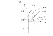
プランジャ10は、筒状のポットP(図4、図5参照)内に進退動可能(摺動可能)に挿入され、ポットPに供給された樹脂Rを押圧する押圧面21aを有するヘッド部11(先端部)を備えている。ここで、プランジャ10は、樹脂Rを押圧する押圧面21aを有するため押圧部材となり、ポットPは、そのプランジャ10が挿入される貫通孔を有するため貫通部材となる。ヘッド部11は、樹脂Rを押圧する押圧面21a(ヘッド上面)を有するフランジ部21と、ヘッド本体部31とが分割可能に構成されている。具体的には、ヘッド部11は、フランジ部21を有する第1ホルダ20と、ヘッド本体部31を有する第2ホルダ30とが一体に組み付けられて構成されている。   The plunger 10 is inserted into a cylindrical pot P (see FIGS. 4 and 5) so as to be movable back and forth (slidable), and has a pressing surface 21a that presses the resin R supplied to the pot P. (Tip). Here, since the plunger 10 has a pressing surface 21a that presses the resin R, it becomes a pressing member, and the pot P becomes a penetrating member because it has a through hole into which the plunger 10 is inserted. The head portion 11 is configured such that a flange portion 21 having a pressing surface 21a (head upper surface) for pressing the resin R and a head main body portion 31 can be divided. Specifically, the head portion 11 is configured by integrally assembling a first holder 20 having a flange portion 21 and a second holder 30 having a head main body portion 31.

第1ホルダ20は、図1に示すように、フランジ部21と、ロッド部24とを有している。フランジ部21は、所定の厚みを有し、ポットPの内径より若干小さい外径に形成されている。ロッド部24は、プランジャ軸10a(図2参照)方向に延在するようにフランジ部21の下面(押圧面21aとは反対の面)に連結されている。第1ホルダ20は、フランジ部21およびロッド部24が一体となるように、例えば合金鋼や超硬合金鋼から形成されてなる。   As shown in FIG. 1, the first holder 20 has a flange portion 21 and a rod portion 24. The flange portion 21 has a predetermined thickness and has an outer diameter slightly smaller than the inner diameter of the pot P. The rod portion 24 is connected to the lower surface (the surface opposite to the pressing surface 21a) of the flange portion 21 so as to extend in the direction of the plunger shaft 10a (see FIG. 2). The first holder 20 is made of, for example, alloy steel or cemented carbide steel so that the flange portion 21 and the rod portion 24 are integrated.

フランジ部21の押圧面21aでは、梨地面(図示せず)が形成されている。また、フランジ部21の外周側面では、押圧面21a側に向かって窄まるようにカーブ(曲面)の付いた、一例として垂直に対してθは15〜20度程度のテーパ面(傾斜面)が形成されている(図10参照)。すなわち、押圧面21aの外周縁部21bでは曲面が形成されている。このため、ヘッド部11(フランジ部21)がドーム状となる。また、ロッド部24には、その径方向に貫通するノックピン孔25が形成されている。このノックピン孔25には、ノックピン19が挿入される(図2参照)。   On the pressing surface 21 a of the flange portion 21, a matte surface (not shown) is formed. Further, on the outer peripheral side surface of the flange portion 21, as an example, a taper surface (inclined surface) having a curve (curved surface) so as to narrow toward the pressing surface 21 a side and having a θ of about 15 to 20 degrees with respect to the vertical direction. It is formed (see FIG. 10). That is, a curved surface is formed at the outer peripheral edge 21b of the pressing surface 21a. For this reason, the head part 11 (flange part 21) becomes a dome shape. Further, the rod part 24 is formed with a knock pin hole 25 penetrating in the radial direction. The knock pin 19 is inserted into the knock pin hole 25 (see FIG. 2).

また、第2ホルダ30は、図1に示すように、ヘッド本体部31と、胴体部32(軸部)とを有している。ヘッド本体部31は、後述のプランジャリング12の受け部として所定の厚みを有し、ポットPの内径より若干小さい外径に形成されている。胴体部32は、プランジャ軸10a方向に延在するようにヘッド本体部31に連結され、ヘッド本体部31よりも縮径して形成されている。第2ホルダ30は、ヘッド本体部31および胴体部32が一体となるように、例えば合金鋼や超硬合金鋼から形成されてなる。   Moreover, the 2nd holder 30 has the head main-body part 31 and the trunk | drum 32 (shaft part), as shown in FIG. The head main body 31 has a predetermined thickness as a receiving portion for the plunger ring 12 described later, and is formed to have an outer diameter slightly smaller than the inner diameter of the pot P. The body portion 32 is connected to the head main body portion 31 so as to extend in the direction of the plunger shaft 10 a, and is formed with a diameter smaller than that of the head main body portion 31. The second holder 30 is made of, for example, alloy steel or cemented carbide steel so that the head main body 31 and the body 32 are integrated.

胴体部32には、第1ホルダ20のロッド部24が挿入される挿入部33がプランジャ軸10a方向に形成されている。また、胴体部32には、胴体部32の径方向に貫通するノックピン孔34が形成されている。このノックピン孔34には、ノックピン19が挿入される(図2参照)。   An insertion portion 33 into which the rod portion 24 of the first holder 20 is inserted is formed in the body portion 32 in the direction of the plunger shaft 10a. The body portion 32 is formed with a knock pin hole 34 penetrating in the radial direction of the body portion 32. The knock pin 19 is inserted into the knock pin hole 34 (see FIG. 2).

ここで、第1ホルダ20と第2ホルダ30の組み付け方法について説明する。まず、第1ホルダ20のロッド部24を、第2ホルダのヘッド本体部31の上端面から挿入部33へ挿入する(図1の矢印参照)。この際、胴体部32のノックピン孔34と、挿入部33に挿入されたロッド部24のノックピン孔25との孔位置を一致させる。次いで、ノックピン孔34およびノックピン孔25を通過するように、胴体部32の外周側面側からノックピン19を挿入する(図2参照)。したがって、ノックピン19により第1ホルダ20が抜け止めされて、第1ホルダ20と第2ホルダ30が組み付けられる。   Here, a method of assembling the first holder 20 and the second holder 30 will be described. First, the rod portion 24 of the first holder 20 is inserted into the insertion portion 33 from the upper end surface of the head main body portion 31 of the second holder (see the arrow in FIG. 1). At this time, the positions of the knock pin hole 34 of the body portion 32 and the knock pin hole 25 of the rod portion 24 inserted into the insertion portion 33 are matched. Next, the knock pin 19 is inserted from the outer peripheral side surface of the body portion 32 so as to pass through the knock pin hole 34 and the knock pin hole 25 (see FIG. 2). Accordingly, the first holder 20 is prevented from coming off by the knock pin 19 and the first holder 20 and the second holder 30 are assembled.

このように、第1ホルダ20と第2ホルダ30とが組み付けられることで、プランジャ軸10aの周方向に、ヘッド部11の外周側面の全周に渡ってリング周溝14が形成される。なお、図1では、説明を明解にするために、ヘッド部11に形成されたリング周溝14を図示している。   Thus, the ring circumferential groove 14 is formed over the entire circumference of the outer peripheral side surface of the head portion 11 in the circumferential direction of the plunger shaft 10 a by assembling the first holder 20 and the second holder 30. In FIG. 1, the ring circumferential groove 14 formed in the head portion 11 is illustrated for clarity of explanation.

本実施形態では、ヘッド本体部31の上端面(フランジ部21側端面)に、上端面から突き出る端面周凸部35を設けている。このため、第1ホルダ20と第2ホルダ30とが組み付けられることで、フランジ部21の下面と、ヘッド本体部31の上端面と、端面周凸部35の外周面とで囲まれた領域がリング周溝14として形成される。すなわち、ヘッド部11では、フランジ部21と、ヘッド本体部31の間であって、プランジャ軸10aの周方向に、ヘッド部11の外周側面の全周に渡ってリング周溝14が形成される。なお、端面周凸部35は、ヘッド本体部31の上端面に限らず、フランジ部21の下面に設けることもできる(図9参照)。   In the present embodiment, an end surface circumferential convex portion 35 protruding from the upper end surface is provided on the upper end surface (end surface on the flange portion 21 side) of the head main body 31. For this reason, by assembling the first holder 20 and the second holder 30, an area surrounded by the lower surface of the flange portion 21, the upper end surface of the head main body portion 31, and the outer peripheral surface of the end surface circumferential convex portion 35 is It is formed as a groove 14. That is, in the head portion 11, the ring circumferential groove 14 is formed over the entire circumference of the outer peripheral side surface of the head portion 11 between the flange portion 21 and the head main body portion 31 and in the circumferential direction of the plunger shaft 10 a. . The end surface circumferential convex portion 35 can be provided not only on the upper end surface of the head main body portion 31 but also on the lower surface of the flange portion 21 (see FIG. 9).

このように形成されるリング周溝14に環状のプランジャリング12が周設される(嵌め込まれる)。本実施形態では、端面周凸部35の外径に対して、プランジャリング12の貫通孔12bの内径を同一としている。したがって、第1ホルダ20と第2ホルダ30とを組み付ける際に、端面周凸部35に環状のプランジャリング12を嵌め込み、第1ホルダ20と第2ホルダ30とでプランジャリング12をホールドする(組み付ける)ことができる。   An annular plunger ring 12 is provided around (inserted into) the ring circumferential groove 14 formed in this way. In the present embodiment, the inner diameter of the through hole 12 b of the plunger ring 12 is the same as the outer diameter of the end surface circumferential convex portion 35. Therefore, when the first holder 20 and the second holder 30 are assembled, the annular plunger ring 12 is fitted into the end surface circumferential convex portion 35, and the plunger ring 12 is held (assembled) by the first holder 20 and the second holder 30. Can do.

また、本実施形態では、ヘッド本体部31の厚みに対して、プランジャリング12の厚みを薄くしている。すなわち、ヘッド本体部31は、プランジャリング12の受け部(支持部)であるため、ヘッド本体部31の厚みをフランジ部21よりも肉厚としている。また、プランジャリング12をフランジ部21でホールドするため、プランジャリング12の厚みに対して、端面周凸部35の厚みをほぼ同一あるいは若干薄くしている。   In the present embodiment, the plunger ring 12 is made thinner than the head main body 31. That is, since the head main body 31 is a receiving portion (supporting portion) for the plunger ring 12, the thickness of the head main body 31 is thicker than that of the flange portion 21. Further, since the plunger ring 12 is held by the flange portion 21, the thickness of the end surface circumferential convex portion 35 is made substantially the same or slightly thinner than the plunger ring 12.

そして、本実施形態では、ヘッド部11の外周側面から突き出るように環状のプランジャリング12をリング周溝14に周設している。図10に記載したように、このプランジャリング12の外径は、フランジ部21やヘッド本体部31の外径よりもa寸法分大きく、ポットPの内径とほぼ同一である。   In this embodiment, an annular plunger ring 12 is provided in the ring circumferential groove 14 so as to protrude from the outer peripheral side surface of the head portion 11. As shown in FIG. 10, the outer diameter of the plunger ring 12 is larger than the outer diameter of the flange portion 21 and the head main body portion 31 by the dimension a, and is almost the same as the inner diameter of the pot P.

このように、ヘッド部11の外周側面から突き出るプランジャリング12を設け、プランジャ10とポットPの隙間を小さくすることで、ヘッド部11の周囲で樹脂Rが漏れるのを防止することができる。すなわち、樹脂漏れによるプランジャ10の進退動抵抗が増加してしまうのを防止することができる。ここで、プランジャリング12は、プランジャ10とポットPの隙間をシールするためシールリングとなる。   Thus, by providing the plunger ring 12 protruding from the outer peripheral side surface of the head portion 11 and reducing the gap between the plunger 10 and the pot P, it is possible to prevent the resin R from leaking around the head portion 11. That is, it is possible to prevent the advance / retreat resistance of the plunger 10 from increasing due to resin leakage. Here, the plunger ring 12 serves as a seal ring for sealing the gap between the plunger 10 and the pot P.

また、ヘッド部11とポットPの間の隙間を小さくし、樹脂漏れを防止することで、プランジャ後端部側(胴体部32側)へ樹脂かすが落下するのを防止し、メンテナンス回数を抑制することができる。また、プランジャリング12の厚みを薄くすることでも、プランジャ10の進退動抵抗が増加してしまうのを防止することができる。また、プランジャリング12に不具合があっても、フランジ部21とヘッド本体部31とを分割することで、容易にプランジャリング12を交換することができ、メンテナンス性を向上することができる。   Further, by reducing the gap between the head portion 11 and the pot P and preventing resin leakage, the resin debris is prevented from dropping to the plunger rear end side (the body portion 32 side), and the number of maintenance is suppressed. be able to. Further, by reducing the thickness of the plunger ring 12, it is possible to prevent the advance / retreat resistance of the plunger 10 from increasing. Even if the plunger ring 12 has a problem, by dividing the flange portion 21 and the head main body portion 31, the plunger ring 12 can be easily replaced, and the maintainability can be improved.

また、本実施形態では、フランジ部21の押圧面21aを梨地面としている。梨地面の押圧面21aでは、樹脂ワックス分が保持されているので、熱硬化された樹脂Rとヘッド部11との離型を補助する(離型を容易にする)ことができる。すなわち、ヘッド部11に熱硬化した樹脂Rが付着するのを防止することができる。したがって、メンテナンス回数を抑制することができる。   Moreover, in this embodiment, the pressing surface 21a of the flange part 21 is made into a pear ground. Since the resin wax component is held on the pressing surface 21a of the matte ground surface, it is possible to assist the mold release between the heat-cured resin R and the head portion 11 (to facilitate the mold release). That is, it is possible to prevent the thermosetting resin R from adhering to the head portion 11. Therefore, the maintenance frequency can be suppressed.

ここで、プランジャリング12には、ポットP内で進退動しても摩耗量の少ない硬質な材質を用いることが好ましい。本実施形態では、金属(例えば、ステンレス鋼やバネ鋼などの鋼材)からなるプランジャリング12を用いている。金属からなるプランジャリング12を用いることで、樹脂からなるものと比較して硬質となり、その耐久性が向上する。したがって、プランジャリング12が破損する割合を極めて低くすることができ、メンテナンス回数を抑制することができる。また、プランジャ10の進退動不良の発生を防止することができる。   Here, it is preferable to use a hard material with a small amount of wear even if the plunger ring 12 moves back and forth in the pot P. In the present embodiment, the plunger ring 12 made of metal (for example, a steel material such as stainless steel or spring steel) is used. By using the plunger ring 12 made of a metal, it becomes harder than that made of a resin, and its durability is improved. Therefore, the rate at which the plunger ring 12 is broken can be made extremely low, and the number of maintenance can be suppressed. In addition, the occurrence of poor advance / retreat failure of the plunger 10 can be prevented.

また、金属からなるプランジャリング12には、表面処理として例えばメッキ処理を施こすことが有効である。メッキ処理により、プランジャリング12の表面には、例えば、ハードCr膜、CrN膜、TiN膜が形成される。このため、プランジャリング12全体がより硬質となってプランジャ10の耐久性、進退動性を向上させることができる。また、プランジャリング12には、他の表面処理として例えば窒化処理を施して窒化層を形成することで進退動性を向上させることも可能である。   Further, it is effective to subject the plunger ring 12 made of metal, for example, to a plating treatment as a surface treatment. By the plating process, for example, a hard Cr film, a CrN film, and a TiN film are formed on the surface of the plunger ring 12. For this reason, the whole plunger ring 12 becomes harder and the durability of the plunger 10 and the advance / retreat performance can be improved. The plunger ring 12 can also be improved in forward and backward movement by forming a nitride layer by performing, for example, nitriding as another surface treatment.

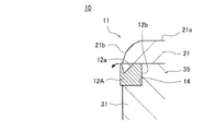
さらに、本実施形態では、図3に示すように、プランジャリング12のフランジ部21側の外周側面において、全周に渡って樹脂溜まり部12a(環状溝部)を形成している。フランジ部21下側においては、ストレート部b寸法(図10参照)があっても良いし、無くとも良い。そして、樹脂溜まり部12aのフランジ部21側の開口縁を面取りし、フランジ部21側で樹脂溜まり部12aの開口をa寸法分広くしている。また、前述したように、押圧面21aの外周縁部21bが曲面に形成されている。このため、ヘッド部11が樹脂Rを押圧する際に、樹脂溜まり部12aに樹脂Rが充填されて(入り込み)、プランジャリング12の外周側面に硬化した樹脂Rからなる樹脂リングRLが形成される。プランジャリング12のフランジ部21との接触部分と樹脂溜りRLとの間には僅かなストレート部c(図10参照)があっても良いし、無くとも良い。   Furthermore, in this embodiment, as shown in FIG. 3, a resin reservoir 12 a (annular groove) is formed over the entire circumference on the outer peripheral side surface of the plunger ring 12 on the flange portion 21 side. On the lower side of the flange portion 21, there may or may not be a straight portion b dimension (see FIG. 10). The opening edge on the flange portion 21 side of the resin reservoir portion 12a is chamfered, and the opening of the resin reservoir portion 12a is widened by the dimension a on the flange portion 21 side. Further, as described above, the outer peripheral edge 21b of the pressing surface 21a is formed in a curved surface. For this reason, when the head part 11 presses the resin R, the resin reservoir 12a is filled (entered) with the resin R, and a resin ring RL made of the cured resin R is formed on the outer peripheral side surface of the plunger ring 12. . There may or may not be a slight straight portion c (see FIG. 10) between the contact portion of the plunger ring 12 with the flange portion 21 and the resin reservoir RL.

このように、押圧面21aの外周縁部21bを曲面とすることで、樹脂溜まり部12aで樹脂Rを溜めて樹脂リングRLを形成することができる。このように、プランジャリング12の外周側面に樹脂リングRLを付けることで、ヘッド部11とポットPの隙間を塞いで(小さくして)、プランジャ10を摺動することができる。したがって、ヘッド部11の周囲で樹脂Rが漏れるのをより防止することができる。樹脂封止後にプランジャリング12とフランジ部21との狭い境で樹脂Rが分断される(千切られる)ことにより(図3参照)、一方は樹脂リングRLとなってプランジャ10側に残り、他方はカル側となる。   Thus, by making the outer peripheral edge 21b of the pressing surface 21a into a curved surface, the resin R can be accumulated in the resin reservoir 12a to form the resin ring RL. Thus, by attaching the resin ring RL to the outer peripheral side surface of the plunger ring 12, the gap between the head portion 11 and the pot P can be closed (smaller), and the plunger 10 can be slid. Therefore, it is possible to further prevent the resin R from leaking around the head portion 11. After resin sealing, the resin R is divided (cut into pieces) at the narrow boundary between the plunger ring 12 and the flange portion 21 (see FIG. 3), so that one becomes the resin ring RL and remains on the plunger 10 side, and the other It becomes the Cal side.

また、ヘッド部11から樹脂リングRLを取り除く際には、フランジ部21とヘッド本体部31とを分割することで、樹脂リングRLが付いたままでプランジャリング12を交換することができる。また、分割されたプランジャリング12から樹脂リングRLを取り外せばよいので、容易にプランジャリング12をクリーニングすることができる。   Further, when the resin ring RL is removed from the head portion 11, the plunger ring 12 can be exchanged with the resin ring RL attached by dividing the flange portion 21 and the head main body portion 31. Further, since the resin ring RL may be removed from the divided plunger ring 12, the plunger ring 12 can be easily cleaned.

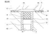
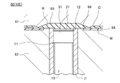
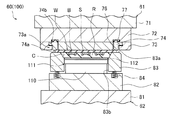
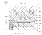
次に、前述のプランジャ10を、トランスファ機構を有する樹脂封止装置100に適用した場合について、図4、図5を参照して説明する。図4、図5は、プランジャ10を備えた樹脂封止装置100の要部(成形金型60)の断面図である。なお、説明を明解にするために、図4、図5では、プランジャ10を側面視で示している。   Next, a case where the above-described plunger 10 is applied to a resin sealing device 100 having a transfer mechanism will be described with reference to FIGS. 4 and 5. 4 and 5 are cross-sectional views of a main part (molding mold 60) of the resin sealing device 100 including the plunger 10. FIG. For clarity of explanation, FIGS. 4 and 5 show the plunger 10 in a side view.

樹脂封止装置100は、例えば、図示しない供給部と収納部との間に、少なくとも一つのプレス部を備えて構成される。各プレス部には、型閉じの状態でキャビティCが形成される成形金型60が少なくとも1つ設けられて、キャビティCまでの樹脂路に溶融した樹脂Rを圧送するプランジャ10が設けられる。   The resin sealing device 100 includes, for example, at least one press unit between a supply unit and a storage unit (not shown). Each press part is provided with at least one molding die 60 in which a cavity C is formed in a closed state, and a plunger 10 that pumps molten resin R into a resin path to the cavity C.

供給部は、ローダ(搬送装置)を用いて被成形品であるワークWや封止するための樹脂Rをプレス部に供給する公知の機構で構成される。また、収納部は、プレス部からアンローダ(搬送装置)を用いて樹脂封止成形された成形品であるワークWを取り出し、収納する公知の機構で構成される。なお、樹脂封止装置100は、供給部および収納部を備えずに、プレス部(成形金型60)のみを備えたマニュアル式であってもよい。   A supply part is comprised by the well-known mechanism which supplies the workpiece | work W which is a to-be-molded product, and resin R for sealing to a press part using a loader (conveyance apparatus). In addition, the storage unit is configured by a known mechanism that takes out and stores the workpiece W, which is a molded product molded by resin sealing, using an unloader (conveying device) from the press unit. The resin sealing device 100 may be a manual type that includes only a press unit (molding die 60) without including a supply unit and a storage unit.

ワークWは、例えば、基板(有機基板、セラミック基板等)やリードフレーム上に複数の電子部品(例えば、半導体チップに限らず、コンデンサ、抵抗等を含む電気、電子部品でも良い)が実装されたものである。樹脂Rは、例えば、タブレット状、液状、顆粒状、粉末状、シート状などの種々の封止用樹脂である。   For example, the workpiece W is mounted with a plurality of electronic components (for example, not only semiconductor chips but also electric and electronic components including capacitors, resistors, etc.) on a substrate (organic substrate, ceramic substrate, etc.) or a lead frame. Is. The resin R is a variety of sealing resins such as tablets, liquids, granules, powders, and sheets.

成形金型60(プレス部)は、上型61(一方の金型)および下型62(他方の金型)と、下型62に設けられて樹脂Rが供給される円筒状のポットPと、ポットPに型開閉方向(上下方向)に進退動可能に収容されたプランジャ10とを備えている。下型62の中央部では、パーティング面で開口するポットPの両側に、ワークWをセットするセット部64が設けられている。   The molding die 60 (press part) includes an upper die 61 (one die) and a lower die 62 (the other die), and a cylindrical pot P provided on the lower die 62 to which the resin R is supplied. And a plunger 10 accommodated in the pot P so as to be movable back and forth in the mold opening / closing direction (vertical direction). In the central portion of the lower mold 62, set portions 64 for setting the workpiece W are provided on both sides of the pot P that opens at the parting surface.

下型62の下方には、プランジャ10を型開閉方向に進退動する駆動機構(図示せず)が設けられている。例えば、駆動機構は、油圧あるいは電動モータによる駆動力を利用するものであり、この駆動機構とプランジャ10とは、駆動機構に設けられた押動ロッドの上端面とプランジャ10の後端部とがキー係合して、抜け止め状態で連結されている。   A drive mechanism (not shown) for moving the plunger 10 back and forth in the mold opening / closing direction is provided below the lower mold 62. For example, the drive mechanism uses a drive force generated by a hydraulic pressure or an electric motor, and the drive mechanism and the plunger 10 include an upper end surface of a push rod provided in the drive mechanism and a rear end portion of the plunger 10. The key is engaged and connected in a retaining state.

成形金型60を用いて成形品を製造するには、まず、型開きした状態において、ポットPに樹脂Rおよびセット部64にワークW(被成形品)が供給される。このとき、ポットP内のプランジャ10のヘッド部11は、パーティング面から後退した位置(待機位置)にある(図4参照)。その後、図4に示すように、型閉じすることによって、上型61と下型62とでワークWがクランプされる。このとき、成形金型60では、キャビティCが形成される。このキャビティCとポットPとは、カル65およびランナ・ゲート66を介して連通される。   In order to manufacture a molded product using the molding die 60, first, in a state where the mold is opened, the resin R is supplied to the pot P and the work W (molded product) is supplied to the set portion 64. At this time, the head portion 11 of the plunger 10 in the pot P is in a position (standby position) retracted from the parting surface (see FIG. 4). Thereafter, as shown in FIG. 4, the workpiece W is clamped by the upper die 61 and the lower die 62 by closing the die. At this time, the cavity C is formed in the molding die 60. The cavity C and the pot P communicate with each other via a cull 65 and a runner gate 66.

続いて、図5に示すように、溶融している樹脂Rを押圧しながら、プランジャ10のヘッド部11が上死点位置まで前進させる。これにより、ポットPからカル65およびランナ・ゲート66を介してキャビティC内へ樹脂Rが圧送(注入)される。そして、キャビティC内を樹脂Rで充填し、これを熱硬化させることで、ワークWが成形品として略完成する。なお、本実施形態では、プランジャ10の先端(ヘッド部11の上死点位置)をカル65内まで前進させない(上げない)こととしている。   Subsequently, as shown in FIG. 5, the head portion 11 of the plunger 10 is advanced to the top dead center position while pressing the molten resin R. As a result, the resin R is pumped (injected) from the pot P into the cavity C through the cull 65 and the runner gate 66. And the work W is substantially completed as a molded article by filling the cavity C with the resin R and thermally curing it. In the present embodiment, the tip of the plunger 10 (the top dead center position of the head portion 11) is not advanced (not raised) into the cull 65.

プランジャ10を備えた樹脂封止装置100によれば、ヘッド部11の周囲、すなわち、ヘッド部11とポットPの間の隙間(ポットPの内周面)での樹脂漏れを防止し、プランジャ10の進退動抵抗が増加するのを抑制して、キャビティC内で樹脂封止した際にボイドが発生するのを防止することができる。したがって、成形品の品質の低下を防止することができる。   According to the resin sealing device 100 including the plunger 10, the resin leakage is prevented around the head portion 11, that is, in the gap between the head portion 11 and the pot P (inner peripheral surface of the pot P). It is possible to prevent the void from being generated when the resin is sealed in the cavity C by suppressing the increase / decrease resistance of the resin. Therefore, it is possible to prevent the quality of the molded product from being deteriorated.

また、樹脂漏れを防止することで、プランジャ後端部側(金型内部)へ樹脂かすが落下するのを防止し、メンテナンス回数を抑制することができる。また、プランジャリング12に不具合があっても、フランジ部21とヘッド本体部31とを分割することで、容易にプランジャリング12を交換することができ、メンテナンス性を向上することができる。したがって、成形品の生産性を向上することができる。   Further, by preventing resin leakage, it is possible to prevent the resin debris from dropping to the plunger rear end side (inside the mold) and to reduce the number of maintenance. Even if the plunger ring 12 has a problem, by dividing the flange portion 21 and the head main body portion 31, the plunger ring 12 can be easily replaced, and the maintainability can be improved. Therefore, the productivity of the molded product can be improved.

(実施形態2)
前記実施形態1では、プランジャリング12の外周側面に樹脂リングRLを形成し、ヘッド部11とポットPの隙間を塞ぐ(あるいは小さくする)場合について説明した。本実施形態では、プランジャリング12とは異なる形状のものを用いる場合について、図6を参照して説明する。図6は、本実施形態に係るプランジャ10(ヘッド部11)を拡大した断面図である。
(Embodiment 2)
In the first embodiment, the case where the resin ring RL is formed on the outer peripheral side surface of the plunger ring 12 to close (or reduce) the gap between the head portion 11 and the pot P has been described. In the present embodiment, a case where a shape different from that of the plunger ring 12 is used will be described with reference to FIG. FIG. 6 is an enlarged cross-sectional view of the plunger 10 (head portion 11) according to the present embodiment.

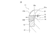
本実施形態に係るプランジャリング12Aは、ヘッド部11の外周側面から突き出るようにリング周溝14に周設されている。このプランジャリング12Aのフランジ部21側の端面には、全周に渡って切り込まれた樹脂溜まり部12a(環状溝部)が形成されている。そして、この樹脂溜まり部12aの開口内に、押圧面21aの外周縁部21bの端がオーバーラップしている。   The plunger ring 12 </ b> A according to the present embodiment is provided around the ring circumferential groove 14 so as to protrude from the outer peripheral side surface of the head portion 11. On the end surface of the plunger ring 12A on the flange portion 21 side, a resin reservoir portion 12a (annular groove portion) that is cut over the entire circumference is formed. The end of the outer peripheral edge 21b of the pressing surface 21a overlaps the opening of the resin reservoir 12a.

前述したように、押圧面21aの外周縁部21bが曲面に形成されている。このため、ヘッド部11がドーム状となる。このヘッド部11が樹脂Rを押圧する際に、樹脂溜まり部12aに樹脂Rが入り込み、プランジャリング12Aの外周部がポットP側(外側)へ拡径する(倒れる)ように変形する。   As described above, the outer peripheral edge 21b of the pressing surface 21a is formed in a curved surface. For this reason, the head part 11 becomes dome shape. When the head portion 11 presses the resin R, the resin R enters the resin reservoir 12a, and the outer peripheral portion of the plunger ring 12A is deformed so as to expand (fall down) to the pot P side (outside).

このように、押圧面21aの外周縁部21bを曲面とすることで、樹脂Rからの圧力を受けてプランジャリング12Aを変形することができる。プランジャリング12Aの外周部が拡径方向へ変形することで、ヘッド部11とポットPの隙間を塞いで(あるいは小さくして)、プランジャ10を摺動することができる。したがって、ヘッド部11の周囲で樹脂Rが漏れるのを防止することができる。   Thus, the plunger ring 12A can be deformed by receiving pressure from the resin R by making the outer peripheral edge portion 21b of the pressing surface 21a a curved surface. Since the outer peripheral part of the plunger ring 12A is deformed in the diameter increasing direction, the gap between the head part 11 and the pot P can be closed (or reduced), and the plunger 10 can be slid. Therefore, it is possible to prevent the resin R from leaking around the head portion 11.

(実施形態3)
前記実施形態1では、プランジャリング12の外周側面に樹脂リングRLを形成し、ヘッド部11とポットPの隙間を塞いだ(あるいは小さくする)場合について説明した。本実施形態では、プランジャリング12とは異なる形状のものを用いる場合について、図7を参照して説明する。図7は、本実施形態に係るプランジャ10(ヘッド部11)を拡大した断面図である。
(Embodiment 3)
In the first embodiment, the case where the resin ring RL is formed on the outer peripheral side surface of the plunger ring 12 to close (or reduce) the gap between the head portion 11 and the pot P has been described. In the present embodiment, a case where a shape different from that of the plunger ring 12 is used will be described with reference to FIG. FIG. 7 is an enlarged cross-sectional view of the plunger 10 (head portion 11) according to the present embodiment.

本実施形態に係るプランジャリング12Bは、ヘッド部11の外周側面から突き出るようにリング周溝14に周設されている。また、リング周溝14には、プランジャリング12Bの他に、ウエッジリング13がプランジャリング12Bと積層して周設されている。リング周溝14に周設されるプランジャリング12B(第1リング)とウエッジリング13(第2リング)とを合わせてプランジャリングとみなせば、これらは分割されて積層されていることとなる。   The plunger ring 12 </ b> B according to the present embodiment is provided around the ring circumferential groove 14 so as to protrude from the outer peripheral side surface of the head portion 11. In addition to the plunger ring 12B, a wedge ring 13 is provided around the ring circumferential groove 14 so as to be laminated with the plunger ring 12B. If the plunger ring 12B (first ring) and the wedge ring 13 (second ring) provided around the ring circumferential groove 14 are regarded as a plunger ring, they are divided and stacked.

このウエッジリング13は、外径がポットPの内径より若干小さく、内径が端面周凸部35の外径とほぼ同一となるように形成されている。このウエッジリング13の材質は、プランジャリング12と同じ材質であってもよいし、異なる材質であってもよい。また、ウエッジリング13は、弾性体であってもよい。   The wedge ring 13 is formed so that the outer diameter is slightly smaller than the inner diameter of the pot P and the inner diameter is substantially the same as the outer diameter of the end surface circumferential convex portion 35. The material of the wedge ring 13 may be the same material as the plunger ring 12 or may be a different material. Further, the wedge ring 13 may be an elastic body.

プランジャリング12Bは、厚みが内径側で薄く、外径側で厚くなるように、ウエッジリング13側の下端面がテーパ面(傾斜面)に形成されている。一方、ウエッジリング13は、厚みが内径側で厚く、外径側で薄くなるように、プランジャリング12B側の上端面がテーパ面(傾斜面)に形成されている。   The plunger ring 12B is formed with a tapered surface (inclined surface) at the lower end surface on the wedge ring 13 side so that the plunger ring 12B is thinner on the inner diameter side and thicker on the outer diameter side. On the other hand, the upper surface of the plunger ring 12B side is formed as a tapered surface (inclined surface) so that the wedge ring 13 is thicker on the inner diameter side and thinner on the outer diameter side.

本実施形態では、プランジャリング12Bのテーパ面(下端面)と、ウエッジリング13のテーパ面(上端面)とを向かい合わせて、プランジャリング12Bとウエッジリング13とを一組としてウエッジ構造としている。すなわち、プランジャリング12Bとウエッジリング13との分割面がテーパ面に形成されている。後述するが、このウエッジ構造は、フランジ部21からの押圧力の反力によってプランジャリング12Bを拡径方向に移動させる。   In this embodiment, the tapered surface (lower end surface) of the plunger ring 12B and the tapered surface (upper end surface) of the wedge ring 13 are opposed to each other, and the plunger ring 12B and the wedge ring 13 are combined into a wedge structure. That is, the dividing surface of the plunger ring 12B and the wedge ring 13 is formed into a tapered surface. As will be described later, this wedge structure moves the plunger ring 12B in the diameter expansion direction by the reaction force of the pressing force from the flange portion 21.

また、本実施形態では、フランジ部21がヘッド本体部31(端面周凸部35)と接しないように組み付けられ、フランジ部21とヘッド本体部31(端面周凸部35)の間には隙間Gが形成されている。一方、フランジ部21がプランジャリング12Bの上端面と接するように組み付けられている。   In the present embodiment, the flange portion 21 is assembled so as not to contact the head main body portion 31 (end surface circumferential convex portion 35), and a gap G is formed between the flange portion 21 and the head main body portion 31 (end surface circumferential convex portion 35). ing. On the other hand, the flange portion 21 is assembled so as to contact the upper end surface of the plunger ring 12B.

このため、ヘッド部11が樹脂Rを押圧する際に、樹脂圧(加圧)がフランジ部21の押圧面21aに加わり、隙間Gの範囲内でフランジ部21がわずかにヘッド本体部31側へ下動する。そして、フランジ部21からの押圧力の反力によって、プランジャリング12Bが拡径方向(ポットP側)に移動される(押し広げられる)。   For this reason, when the head portion 11 presses the resin R, a resin pressure (pressurization) is applied to the pressing surface 21a of the flange portion 21, and the flange portion 21 slightly moves toward the head main body portion 31 within the gap G. Move down. Then, due to the reaction force of the pressing force from the flange portion 21, the plunger ring 12 </ b> B is moved (pushed apart) in the diameter increasing direction (pot P side).

プランジャリング12Bが拡径方向へ移動することで、ヘッド部11とポットPの隙間を塞いで(あるいは小さくして)、プランジャ10を摺動することができる。したがって、ヘッド部11の周囲で樹脂Rが漏れるのを防止することができる。なお、フランジ部21からの押圧力の反力によってプランジャリング12Bが拡径方向に移動されるのであれば、プランジャリング12Bとウエッジリング13を上下逆に重ねることもできる。   By moving the plunger ring 12B in the diameter expanding direction, the gap between the head portion 11 and the pot P can be closed (or reduced), and the plunger 10 can be slid. Therefore, it is possible to prevent the resin R from leaking around the head portion 11. In addition, if the plunger ring 12B is moved in the diameter expansion direction by the reaction force of the pressing force from the flange portion 21, the plunger ring 12B and the wedge ring 13 can be stacked upside down.

(実施形態4)
前記実施形態3では、プランジャリング12Bとウエッジリング13とを一組としたウエッジ構造を用い、プランジャリング12Bがフランジ部21からの押圧力の反力によって拡径方向に移動する場合について説明した。本実施形態では、ウエッジリング13の代わりに、リング周溝14の形状を変える場合について、図8を参照して説明する。図8は、本実施形態に係るプランジャ10(ヘッド部11)を拡大した断面図である。
(Embodiment 4)
In the third embodiment, a case where a wedge structure in which the plunger ring 12B and the wedge ring 13 are paired is used and the plunger ring 12B moves in the diameter expansion direction by the reaction force of the pressing force from the flange portion 21 has been described. In the present embodiment, a case where the shape of the ring circumferential groove 14 is changed instead of the wedge ring 13 will be described with reference to FIG. FIG. 8 is an enlarged cross-sectional view of the plunger 10 (head portion 11) according to the present embodiment.

本実施形態に係るプランジャリング12Bは、ヘッド部11の外周側面から突き出るようにリング周溝14に周設されている。このプランジャリング12Bは、厚みが内径側で薄く、外径側で厚くなるように、下端面がテーパ面に形成されている。そして、本実施形態では、このプランジャリング12Bが嵌め込まれる端面周凸部35の裾部が、プランジャリング12Bのテーパ面に対応したテーパ面に形成されている。   The plunger ring 12 </ b> B according to the present embodiment is provided around the ring circumferential groove 14 so as to protrude from the outer peripheral side surface of the head portion 11. The plunger ring 12B has a tapered lower end surface that is thin on the inner diameter side and thicker on the outer diameter side. And in this embodiment, the skirt part of the end surface surrounding convex part 35 in which this plunger ring 12B is fitted is formed in the taper surface corresponding to the taper surface of the plunger ring 12B.

すなわち、プランジャリング12Bとリング周溝14(ヘッド部11)との当接面がテーパ面に形成されている。このように、本実施形態では、プランジャリング12Bのテーパ面(下端面)と、リング周溝14のテーパ面とを向かい合わせて、ウエッジ構造としている。   That is, the contact surface between the plunger ring 12B and the ring circumferential groove 14 (head portion 11) is formed as a tapered surface. Thus, in this embodiment, the tapered surface (lower end surface) of the plunger ring 12B and the tapered surface of the ring circumferential groove 14 are opposed to each other to form a wedge structure.

このため、ヘッド部11が樹脂Rを押圧する際に、樹脂圧(加圧)がフランジ部21の押圧面21aに加わり、隙間Gの範囲内でフランジ部21がわずかにヘッド本体部31側へ下動する。そして、フランジ部21からの押圧力の反力によって、プランジャリング12Bが拡径方向(ポットP側)に移動する(押し広げられる)。プランジャリング12Bが拡径方向へ移動することで、ヘッド部11とポットPの隙間を塞いで(あるいは小さくして)、プランジャ10を摺動することができる。したがって、ヘッド部11の周囲で樹脂Rが漏れるのを防止することができる。   For this reason, when the head portion 11 presses the resin R, a resin pressure (pressurization) is applied to the pressing surface 21a of the flange portion 21, and the flange portion 21 slightly moves toward the head main body portion 31 within the gap G. Move down. The plunger ring 12B is moved (pushed and expanded) in the diameter expansion direction (pot P side) by the reaction force of the pressing force from the flange portion 21. By moving the plunger ring 12B in the diameter expanding direction, the gap between the head portion 11 and the pot P can be closed (or reduced), and the plunger 10 can be slid. Therefore, it is possible to prevent the resin R from leaking around the head portion 11.

(実施形態5)
前記実施形態4では、ヘッド本体部31側にリング周溝14を設け、そのリング周溝14にウエッジ構造を構成するテーパ面を形成した場合について説明した。本実施形態では、フランジ部21側にリング周溝14を設け、そのリング周溝14にウエッジ構造を構成するテーパ面を形成した場合について、図9を参照して説明する。図9は、本実施形態に係るプランジャ10(ヘッド部11)を拡大した断面図である。
(Embodiment 5)
In the fourth embodiment, the case where the ring circumferential groove 14 is provided on the head main body 31 side and the tapered surface constituting the wedge structure is formed in the ring circumferential groove 14 has been described. In the present embodiment, a case where the ring circumferential groove 14 is provided on the flange portion 21 side and a tapered surface forming a wedge structure is formed in the ring circumferential groove 14 will be described with reference to FIG. FIG. 9 is an enlarged cross-sectional view of the plunger 10 (head portion 11) according to the present embodiment.

本実施形態に係るプランジャリング12Cは、ヘッド部11の外周側面から突き出るようにリング周溝14に周設されている。このプランジャリング12Cは、厚み方向上部側で内径が大きく、厚み方向下部側で内径が小さくなるように、内周面(貫通孔12bの内壁面)がテーパ面となったウエッジ構造に形成されている。そして、本実施形態では、このプランジャリング12Cが嵌め込まれる端面周凸部35が、フランジ部21の下端面に設けられており、その端面周凸部35の外周側面が、プランジャリング12Cのテーパ面に対応したテーパ面に形成されている。   The plunger ring 12 </ b> C according to the present embodiment is provided around the ring circumferential groove 14 so as to protrude from the outer peripheral side surface of the head portion 11. The plunger ring 12C is formed in a wedge structure in which the inner peripheral surface (the inner wall surface of the through hole 12b) is a tapered surface so that the inner diameter is large on the upper side in the thickness direction and smaller on the lower side in the thickness direction. Yes. In this embodiment, the end surface circumferential convex portion 35 into which the plunger ring 12C is fitted is provided on the lower end surface of the flange portion 21, and the outer peripheral side surface of the end surface circumferential convex portion 35 is a taper corresponding to the tapered surface of the plunger ring 12C. Formed on the surface.

すなわち、プランジャリング12Cとリング周溝14(ヘッド部11)との当接面がテーパ面に形成されている。このように、本実施形態では、プランジャリング12Cのテーパ面(内周面)と、リング周溝14のテーパ面とを向かい合わせて、ウエッジ構造としている。   That is, the contact surface between the plunger ring 12C and the ring circumferential groove 14 (head portion 11) is formed into a tapered surface. Thus, in the present embodiment, the tapered surface (inner peripheral surface) of the plunger ring 12C and the tapered surface of the ring peripheral groove 14 are opposed to each other to form a wedge structure.

このため、ヘッド部11が樹脂Rを押圧する際に、樹脂圧(加圧)がフランジ部21の押圧面21aに加わり、隙間Gの範囲内でフランジ部21がわずかにヘッド本体部31側へ下動する。そして、フランジ部21からの押圧力の反力によって、プランジャリング12Cが拡径方向(ポットP側)に移動する(押し広げられる)。プランジャリング12Cが拡径方向に移動することで、ヘッド部11とポットPの隙間を塞いで(あるいは小さくして)、プランジャ10を摺動することができる。したがって、ヘッド部11の周囲で樹脂Rが漏れるのを防止することができる。   For this reason, when the head portion 11 presses the resin R, a resin pressure (pressurization) is applied to the pressing surface 21a of the flange portion 21, and the flange portion 21 slightly moves toward the head main body portion 31 within the gap G. Move down. Then, due to the reaction force of the pressing force from the flange portion 21, the plunger ring 12 </ b> C moves (is pushed and expanded) in the diameter expansion direction (the pot P side). By moving the plunger ring 12C in the diameter increasing direction, the gap between the head portion 11 and the pot P can be closed (or reduced), and the plunger 10 can be slid. Therefore, it is possible to prevent the resin R from leaking around the head portion 11.

(実施形態6)
本発明の実施形態に係る樹脂封止装置100の要部である圧縮成形方式の成形金型60について図11を参照して説明する。図11は、樹脂封止装置100の要部である成形金型60(対をなす上型61および下型62)の断面図である。図11に示すプランジャ10(側面が示されている。)は、前記実施形態1〜5で説明したヘッド部11(端部)を有し、キャビティC(キャビティ凹部)の底面で開口(連通)する円筒状のポットP内に進退動可能に挿入して設けられている。図11に示す成形金型60は、公知の型開閉機構によって型開きしている(上型61と下型62とが離隔している)状態であり、上型61にワークW、下型62のキャビティCに樹脂Rがセット(配置)されている。図11に示すワークWは、基板S(例えば、配線基板)の片面でマトリクス状に複数の電子部品B(例えば、半導体チップ)が表面実装されたものである。また、図11に示す樹脂Rは、顆粒状のものであるが、液状、粉状、タブレット状のものであってもよい。なお、プランジャ10の個数、大きさ、形状には、図11に示すものに限定されず、金型構成を上下逆にしてプランジャ10およびキャビティCを上型61に設けてもよい。
(Embodiment 6)
A compression-molding molding die 60, which is a main part of the resin sealing device 100 according to the embodiment of the present invention, will be described with reference to FIG. FIG. 11 is a cross-sectional view of a molding die 60 (a pair of an upper die 61 and a lower die 62) that is a main part of the resin sealing device 100. A plunger 10 (a side surface is shown) shown in FIG. 11 has the head portion 11 (end portion) described in the first to fifth embodiments, and has an opening (communication) at the bottom surface of the cavity C (cavity recess). It is inserted into a cylindrical pot P that can move forward and backward. The molding die 60 shown in FIG. 11 is in a state where the mold is opened by a known mold opening / closing mechanism (the upper mold 61 and the lower mold 62 are separated from each other). Resin R is set (arranged) in the cavity C. A workpiece W shown in FIG. 11 is obtained by surface-mounting a plurality of electronic components B (for example, semiconductor chips) in a matrix on one side of a substrate S (for example, a wiring substrate). Moreover, although resin R shown in FIG. 11 is a granular thing, it may be liquid, a powder form, and a tablet form. The number, size, and shape of the plunger 10 are not limited to those shown in FIG. 11, and the plunger 10 and the cavity C may be provided in the upper mold 61 with the mold configuration turned upside down.

図11に示す上型61(成形金型10の一方の金型)は、ベース71と、チェイス72と、ガイド73と、インサート74とを備えている。これらは金型ブロックであり、組み付けられて上型61を構成するものである。ベース71は、図示しない固定プラテンに固定されている。このベース71には、チェイス72が固定されている。このチェイス72には、ベース71側とは反対側の外周部にガイド73が固定されている。このガイド73には、チェイス72と当接するように、インサート74が支持されている。   An upper mold 61 (one mold of the molding mold 10) shown in FIG. 11 includes a base 71, a chase 72, a guide 73, and an insert 74. These are mold blocks that are assembled to form the upper mold 61. The base 71 is fixed to a fixed platen (not shown). A chase 72 is fixed to the base 71. In the chase 72, a guide 73 is fixed to the outer peripheral portion opposite to the base 71 side. An insert 74 is supported by the guide 73 so as to contact the chase 72.

インサート74は、下方に凸となるように両側をガイド73で支持されており、下型62側にワークWを吸着保持する吸着面74a(金型クランプ面74aともいう)および外周側部に段差部74bが形成された断面凸状となっている。また、ガイド73は、内側に段部73aが形成され、断面L字状となっている。このため、インサート74の段部74bと、ガイド73の段部73aとが係合することによって、ガイド73には、インサート74が支持される。   The insert 74 is supported by guides 73 on both sides so as to protrude downward, a suction surface 74a (also referred to as a mold clamp surface 74a) for sucking and holding the workpiece W on the lower die 62 side, and a step on the outer peripheral side portion. The section 74b is formed with a convex section. Further, the guide 73 has a stepped portion 73a on the inner side and has an L-shaped cross section. For this reason, the insert 74 is supported by the guide 73 by the step 74 b of the insert 74 and the step 73 a of the guide 73 engaging with each other.

また、インサート74には吸着面74aに通じるエア吸引路76が形成されている。このエア吸引路76は、チェイス72に形成されているエア吸引路(図示せず)と接続され、さらに、成形金型60外で設けられているエアを吸引する吸引装置(図示せず)と接続されている。また、インサート74とチェイス72との間にはリング状のシール部材77(例えば、Oリング)が挟み込まれており、エア吸引路76の気密性を確保するようになっている。このため、吸引装置が作動すると、エア吸引路76などを介してワークWがインサート74の吸着面74aに吸着保持されることとなる。   In addition, an air suction path 76 communicating with the suction surface 74a is formed in the insert 74. The air suction path 76 is connected to an air suction path (not shown) formed in the chase 72, and further, a suction device (not shown) for sucking air provided outside the molding die 60. It is connected. In addition, a ring-shaped seal member 77 (for example, an O-ring) is sandwiched between the insert 74 and the chase 72 so as to ensure the airtightness of the air suction path 76. For this reason, when the suction device is activated, the workpiece W is sucked and held on the suction surface 74a of the insert 74 via the air suction path 76 and the like.

図11に示す下型62(成形金型10の他方の金型)は、ベース81と、チェイス82と、クランパ83と、ポットPと、プランジャ10とを備えている。これらは金型ブロックであり、組み付けられて下型62を構成するものである。ベース81は、図示しない可動プラテンに固定されている。このベース81には、チェイス82が固定されている。   A lower mold 62 (the other mold of the molding mold 10) shown in FIG. 11 includes a base 81, a chase 82, a clamper 83, a pot P, and a plunger 10. These are mold blocks that are assembled to form the lower mold 62. The base 81 is fixed to a movable platen (not shown). A chase 82 is fixed to the base 81.

このチェイス82では、クランパ83がチェイス82との間に弾装された弾性部材84により常時上方に付勢されている。クランパ83の中央部では、厚さ方向に貫通する貫通孔が形成されており、この貫通孔に筒状のポットPが抜け止めされて固定されている。下型62のクランパ83には、金型クランプ面83aから窪んで開口するキャビティCが形成されている。このキャビティCの底面にポットPが設けられており、このポットPには、その内部で型閉じ動作に応じて相対的に進退動(往復動)するプランジャリング12(シールリング)を有するプランジャ10が設けられている。   In this chase 82, the clamper 83 is always urged upward by an elastic member 84 elastically mounted between the chase 82. A through-hole penetrating in the thickness direction is formed in the center portion of the clamper 83, and the cylindrical pot P is secured to the through-hole so as not to come off. The clamper 83 of the lower mold 62 is formed with a cavity C that is recessed from the mold clamp surface 83a and opens. A pot P is provided on the bottom surface of the cavity C. The pot P has a plunger ring 12 (seal ring) that relatively moves forward and backward (reciprocates) in accordance with the mold closing operation. Is provided.

ここで、プランジャ10が、クランパ83に対して相対的に進退動する構成について具体的に説明する。キャビティC(キャビティ凹部)が形成されたクランパ83が、チェイス82に弾性部材84を介して組み付けられている。このクランパ83の貫通孔(ポットP)に挿入されるプランジャ10がチェイス82に固定して組み付けられている。このため、成形金型60の型閉じの際、弾性部材84を押し縮ませてクランパ83を動かすことにより、プランジャ10を相対的に上昇させることができる。すなわち、ポットP内でプランジャ10は、可動部材となって型閉じ動作に応じて相対的に進退動(往復動)することとなる。   Here, the configuration in which the plunger 10 moves forward and backward relative to the clamper 83 will be specifically described. A clamper 83 in which a cavity C (cavity recess) is formed is assembled to the chase 82 via an elastic member 84. The plunger 10 inserted into the through hole (pot P) of the clamper 83 is fixed and assembled to the chase 82. For this reason, when the mold 60 is closed, the plunger 10 can be relatively raised by moving the clamper 83 by pressing and contracting the elastic member 84. That is, in the pot P, the plunger 10 becomes a movable member and relatively moves back and forth (reciprocates) according to the mold closing operation.

本実施形態では、プランジャ10として、例えば、図3に示したような、平面視(クランプ面視)円形状のヘッド部11に設けられた周溝14にヘッド部11より外形が大きく、樹脂溜まり部12a(環状溝部)が形成された円形環状のプランジャリング12を有するものを用いている。このようなプランジャリング12を用いることで、プランジャ10によって樹脂Rを押圧する際に、プランジャ10(可動部材)の摺動箇所(プランジャ10とポットPとの隙間)から樹脂Rが漏れるのを防止することができる。また、プランジャリング12に不具合があった場合(例えば、摺動抵抗が増大してしまうなど)、プランジャリング12自体を容易に交換することができ、プランジャ10(可動部材)のメンテナンス性を向上させることができる。なお、図6、図7、図8、図9に示したようなプランジャリング12Bを用いることもでき、同様の作用効果を得ることができる。   In this embodiment, as the plunger 10, for example, as shown in FIG. 3, the circumferential groove 14 provided in the circular head portion 11 in plan view (clamp surface view) has a larger outer shape than the head portion 11, and the resin pool What has the circular annular plunger ring 12 in which the part 12a (annular groove part) was formed is used. By using such a plunger ring 12, when the resin R is pressed by the plunger 10, the resin R is prevented from leaking from the sliding portion of the plunger 10 (movable member) (the gap between the plunger 10 and the pot P). can do. Moreover, when there is a malfunction in the plunger ring 12 (for example, sliding resistance increases), the plunger ring 12 itself can be easily replaced, and the maintainability of the plunger 10 (movable member) is improved. be able to. In addition, the plunger ring 12B as shown in FIG. 6, FIG. 7, FIG. 8, and FIG. 9 can also be used, and the same effect can be obtained.

このようなプランジャ10を備える成形金型60(樹脂封止装置100)の動作方法(樹脂成形方法)は、まず、型開きした状態で、金型内部にワークWおよび樹脂Rをセット(配置)する。ワークWは、図示しないローダによって金型内部へ搬入(供給)され、吸着面74aにセットされる。また、樹脂Rは、図示しないローダによって金型内部へ搬入(供給)され、ポットPおよびキャビティC(キャビティ凹部)内にセットされる(図11参照)。次いで、型開閉機構によって型閉じしていき、上型61と下型62とでワークWをクランプする。これにより、基板Sが上型61の金型クランプ面74aと、下型62の金型クランプ面83aとの間に挟まれ、電子部品BがキャビティC(キャビティ凹部が基板Sによって閉塞されたもの)内に収容される。なお、図示しない減圧機構によってキャビティC内は減圧されている。   The operation method (resin molding method) of the molding die 60 (resin sealing device 100) provided with such a plunger 10 is as follows. First, the workpiece W and the resin R are set (arranged) inside the die while the mold is opened. To do. The workpiece W is carried (supplied) into the mold by a loader (not shown) and set on the suction surface 74a. Resin R is carried (supplied) into the mold by a loader (not shown), and set in pot P and cavity C (cavity recess) (see FIG. 11). Next, the mold is closed by the mold opening / closing mechanism, and the workpiece W is clamped by the upper mold 61 and the lower mold 62. As a result, the substrate S is sandwiched between the mold clamping surface 74a of the upper mold 61 and the mold clamping surface 83a of the lower mold 62, and the electronic component B is cavity C (the cavity recess is closed by the substrate S). ). Note that the inside of the cavity C is decompressed by a decompression mechanism (not shown).

続いて、型開閉機構によって更に成形金型60を型閉じする(型締めする)ことによって弾性部材84を押し縮め、クランパ83に対してプランジャ10を相対的に上昇させる。これにより、キャビティC内で溶融している樹脂Rがプランジャ10で押圧され、樹脂RがキャビティC内で充填される。次いで、キャビティC内で充填された樹脂Rを所定の樹脂圧で保持(すなわち保圧)して、成形金型60を所定温度に加熱することによって樹脂Rを熱硬化(キュア)させる。その後、成形金型60を型開きして、図示しないアンローダによって、ワークW(成形品)が成形金型60から取り出されて収納部に収納される。   Subsequently, the mold member 60 is further closed (clamped) by the mold opening / closing mechanism, whereby the elastic member 84 is pressed and contracted, and the plunger 10 is raised relative to the clamper 83. Accordingly, the resin R melted in the cavity C is pressed by the plunger 10 and the resin R is filled in the cavity C. Next, the resin R filled in the cavity C is held at a predetermined resin pressure (that is, holding pressure), and the molding die 60 is heated to a predetermined temperature to cure (cure) the resin R. Thereafter, the molding die 60 is opened, and the workpiece W (molded product) is taken out from the molding die 60 and stored in the storage unit by an unloader (not shown).

(実施形態7)
本発明の実施形態に係る樹脂封止装置100の要部である圧縮成形方式の成形金型60について図12を参照して説明する。図12は、樹脂封止装置100の要部である成形金型60(対をなす上型61および下型62)の断面図である。この樹脂封止装置100は、例えば、図示しない供給部と収納部との間に、少なくとも一つの成形金型60を有するプレス部を備えて構成される。図12に示す成形金型60は、下型62に設けられた平面視(クランプ面視)矩形状のキャビティC(キャビティ凹部)が閉塞されるよう型閉じしている(上型61と下型62とが近接し、ワークWをクランプしている)状態である。図12に示すワークWは、基板S(例えば、配線基板)の片面でマトリクス状に複数の電子部品B(例えば、半導体チップ)がワイヤボンディング実装されたものであり、上型61にセット(配置)されている。また、図12に示す樹脂Rは、顆粒状、液状、粉状などの形状したものが溶融した状態となって、下型62のキャビティC内を充填している。なお、キャビティCを上型61に設けるように、金型構成を上下逆にしてもよい。
(Embodiment 7)
A compression molding mold 60, which is a main part of the resin sealing device 100 according to the embodiment of the present invention, will be described with reference to FIG. FIG. 12 is a cross-sectional view of a molding die 60 (a pair of an upper die 61 and a lower die 62) that is a main part of the resin sealing device 100. The resin sealing device 100 includes, for example, a press unit having at least one molding die 60 between a supply unit and a storage unit (not shown). The mold 60 shown in FIG. 12 is closed so that a cavity C (cavity recess) in a plan view (clamp view) provided in the lower mold 62 is closed (upper mold 61 and lower mold). 62 is approaching, and the workpiece W is clamped). A workpiece W shown in FIG. 12 is obtained by wire bonding mounting a plurality of electronic components B (for example, semiconductor chips) in a matrix on one side of a substrate S (for example, a wiring substrate). ) Further, the resin R shown in FIG. 12 is in a melted state in the form of granules, liquid, powder, etc., and fills the cavity C of the lower mold 62. Note that the mold configuration may be turned upside down so that the cavity C is provided in the upper mold 61.

図12に示す上型61は、図11に示した上型61と同様の構成となっている。他方、図12に示す下型62は、ベース81と、チェイス82と、クランパ83と、キャビティ駒110とを備えている。これらは金型ブロックであり、組み付けられて下型62を構成するものである。ベース81は、図示しない可動プラテンに固定されている。このベース81には、チェイス82が固定されている。チェイス82では、クランパ83がチェイス82との間に弾装された弾性部材84により常時上方に付勢されている。クランパ83の中央部では、その厚さ方向に貫通する貫通孔83b(収納部)が形成されている。この金型クランパ83の貫通孔83bに挿入されるキャビティ駒110がチェイス82に固定して組み付けられている。このため、成形金型60の型閉じの際、弾性部材84を押し縮ませてクランパ83を動かすことにより、キャビティ駒110を相対的に上昇させることができる。すなわち、クランパ83の貫通孔83b内でキャビティ駒110は、可動部材となって型閉じ動作に応じて相対的に進退動(往復動)することとなる。このため、キャビティ駒110は、キャビティC内に充填された樹脂Rを押圧することができる。なお、キャビティ駒110の進退動によってキャビティC(キャビティ凹部)の深さ(容積)が変わるため、キャビティCが可動キャビティに構成されることとなる。   The upper mold 61 shown in FIG. 12 has the same configuration as the upper mold 61 shown in FIG. On the other hand, the lower mold 62 shown in FIG. 12 includes a base 81, a chase 82, a clamper 83, and a cavity piece 110. These are mold blocks that are assembled to form the lower mold 62. The base 81 is fixed to a movable platen (not shown). A chase 82 is fixed to the base 81. In the chase 82, the clamper 83 is always urged upward by an elastic member 84 elastically mounted between the chase 82. In the center portion of the clamper 83, a through-hole 83b (storage portion) that penetrates in the thickness direction is formed. The cavity piece 110 to be inserted into the through hole 83 b of the mold clamper 83 is fixedly assembled to the chase 82. For this reason, when the mold 60 is closed, the cavity piece 110 can be relatively raised by pressing the elastic member 84 and moving the clamper 83. That is, in the through hole 83b of the clamper 83, the cavity piece 110 becomes a movable member and relatively moves back and forth (reciprocates) according to the mold closing operation. For this reason, the cavity piece 110 can press the resin R filled in the cavity C. In addition, since the depth (volume) of the cavity C (cavity recess) is changed by the forward and backward movement of the cavity piece 110, the cavity C is configured as a movable cavity.

そして、下型62のクランパ83には、金型クランプ面83aから窪んで開口するキャビティC(キャビティ凹部)が設けられている。具体的には、キャビティCの底面がクランパ83の貫通孔83bに挿入されたキャビティ駒110の上端面で構成され、キャビティCの側面(内壁面)がクランパ83の貫通孔83bから金型クランプ面83aへ拡径するクランパ83のテーパ面で構成されている。本実施形態では、キャビティCは平面視(クランプ面視)矩形状であり、このキャビティCの底面を構成するキャビティ駒110の平面視形状も矩形状である。   The clamper 83 of the lower mold 62 is provided with a cavity C (cavity recess) that is recessed from the mold clamping surface 83a and opens. Specifically, the bottom surface of the cavity C is constituted by the upper end surface of the cavity piece 110 inserted into the through hole 83b of the clamper 83, and the side surface (inner wall surface) of the cavity C extends from the through hole 83b of the clamper 83 to the mold clamping surface. It is composed of a tapered surface of a clamper 83 that expands to 83a. In this embodiment, the cavity C has a rectangular shape in plan view (clamp surface view), and the shape of the cavity piece 110 that forms the bottom surface of the cavity C also has a rectangular shape.

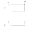
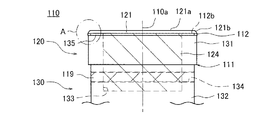
ここで、本実施形態に係るキャビティ駒110について、主として図13〜図18を参照して説明する。図13は、キャビティ駒110の組み付けられる前の分解図である。また、図14〜図16は、キャビティ駒110を構成する部材の説明図である。図14において、(a)は(b)および(c)中の矢印a視の平面図、(b)は(a)および(c)中の矢印b視の側面図、(c)は(a)および(b)中の矢印c視の正面図である。図15および図16のそれぞれについても同様である。また、図17は、キャビティ駒110の組み付けられた後の側面図である。また、図18は、図17に示す円A(一点鎖線)で囲まれたキャビティ駒110(ヘッド部111)を拡大した断面図である。なお、図13〜図17では、透視あるいは仮想視したものを破線で示している。   Here, the cavity piece 110 according to the present embodiment will be described mainly with reference to FIGS. 13 to 18. FIG. 13 is an exploded view before the cavity piece 110 is assembled. 14-16 is explanatory drawing of the member which comprises the cavity piece 110. FIG. 14, (a) is a plan view of the arrow a in (b) and (c), (b) is a side view of the arrow b in (a) and (c), and (c) is (a) It is a front view of the arrow c view in () and (b). The same applies to each of FIGS. 15 and 16. FIG. 17 is a side view after the cavity piece 110 is assembled. 18 is an enlarged cross-sectional view of the cavity piece 110 (head portion 111) surrounded by a circle A (dashed line) shown in FIG. Note that in FIG. 13 to FIG. 17, a perspective view or a virtual view is indicated by a broken line.

前述したように、クランパ83の貫通孔83b内に相対的に進退動可能に挿入されるキャビティ駒110(図12、図17参照)は、キャビティCの底面に供給された樹脂Rを押圧する押圧面121a(ヘッド上面)を有するヘッド部111(先端部)を備えている。このヘッド部111は、樹脂Rを押圧する押圧面121a(ヘッド上面)を有するフランジ部121を有する上ホルダ120と、ヘッド本体部131を有する下ホルダ130と、上ホルダ120と下ホルダ130との間で挟まれるキャビティリング112とが一体に組み付けられて構成されている。ここで、キャビティ駒110は、樹脂Rを押圧する押圧面121aを有するため押圧部材となり、クランパ83は、そのキャビティ駒110が挿入される貫通孔83bを有するため貫通部材となる。また、キャビティリング112は、キャビティ駒110とクランパ83の隙間をシールするためシールリングとなる。本実施形態では、キャビティCの底面形状として、キャビティ駒110のヘッド部111の端面が矩形状に構成されている。また、ヘッド部111に組み付けられるキャビティリング112(図13、図15参照)は、所定幅の平面視矩形環状であり、貫通孔112bを有している。   As described above, the cavity piece 110 (see FIGS. 12 and 17) that is inserted into the through hole 83b of the clamper 83 so as to be relatively movable back and forth presses the resin R supplied to the bottom surface of the cavity C. A head portion 111 (tip portion) having a surface 121a (head upper surface) is provided. The head portion 111 includes an upper holder 120 having a flange portion 121 having a pressing surface 121 a (head upper surface) for pressing the resin R, a lower holder 130 having a head main body portion 131, and the upper holder 120 and the lower holder 130. A cavity ring 112 sandwiched between them is integrally assembled. Here, the cavity piece 110 is a pressing member because it has a pressing surface 121a for pressing the resin R, and the clamper 83 is a penetration member because it has a through hole 83b into which the cavity piece 110 is inserted. The cavity ring 112 serves as a seal ring for sealing the gap between the cavity piece 110 and the clamper 83. In the present embodiment, as the bottom shape of the cavity C, the end surface of the head portion 111 of the cavity piece 110 is formed in a rectangular shape. Further, the cavity ring 112 (see FIGS. 13 and 15) assembled to the head portion 111 has a rectangular shape in a plan view and has a through hole 112b.

また、上ホルダ120(図13、図14参照)は、平面視矩形状のフランジ部121および突起部124(ロッド部)を有している。フランジ部121は、所定の厚みを有し、クランパ83の貫通孔83bの大きさより若干小さい大きさに形成されている。フランジ部121の外周縁部121b全体では、押圧面121a側に向かって窄まるようにカーブ(曲面)の付いたテーパ面(傾斜面)が形成されている(例えば、図10に示すように、θが15〜20度程度)。突起部124は、中心軸110a(図17参照)方向に延在するようにフランジ部121の下面(押圧面121aとは反対の面)から突起(連結)している。また、突起部124には、その長手方向に貫通するノックピン孔125が形成されている。このノックピン孔125には、ノックピン119が挿入される(図17参照)。上ホルダ120は、フランジ部121および突起部124が一体となるように、例えば合金鋼や超硬合金鋼から形成されてなる。   Further, the upper holder 120 (see FIGS. 13 and 14) has a flange portion 121 and a projection portion 124 (rod portion) that are rectangular in plan view. The flange portion 121 has a predetermined thickness and is formed in a size slightly smaller than the size of the through hole 83 b of the clamper 83. The entire outer peripheral edge 121b of the flange 121 is formed with a tapered surface (inclined surface) with a curve (curved surface) so as to be narrowed toward the pressing surface 121a (for example, as shown in FIG. θ is about 15 to 20 degrees). The protrusion 124 protrudes (connects) from the lower surface of the flange 121 (the surface opposite to the pressing surface 121a) so as to extend in the direction of the central axis 110a (see FIG. 17). Further, the projection 124 is formed with a knock pin hole 125 penetrating in the longitudinal direction. A knock pin 119 is inserted into the knock pin hole 125 (see FIG. 17). The upper holder 120 is made of, for example, alloy steel or cemented carbide steel so that the flange portion 121 and the protruding portion 124 are integrated.

また、下ホルダ130(図13、図16参照)は、平面視矩形状のヘッド本体部131および胴体部132(軸部)を有している。ヘッド本体部131は、キャビティリング112の受け部として所定の厚みを有し、貫通孔83bの大きさより若干小さく形成されている。胴体部132は、中心軸110a方向に延在するようにヘッド本体部131に連結され、ヘッド本体部131よりも若干小さく形成されている。下ホルダ130は、ヘッド本体部131および胴体部132が一体となるように、例えば合金鋼や超硬合金鋼から形成されてなる。胴体部132には、上ホルダ120の突起部124が挿入される挿入部133が中心軸110a方向に形成されている。また、胴体部132には、胴体部132の長手方向に貫通するノックピン孔134が形成されている。このノックピン孔134には、ノックピン119が挿入される(図17参照)。   Further, the lower holder 130 (see FIGS. 13 and 16) includes a head body 131 and a body 132 (shaft) that are rectangular in plan view. The head main body 131 has a predetermined thickness as a receiving portion of the cavity ring 112 and is formed slightly smaller than the size of the through hole 83b. The body portion 132 is connected to the head main body portion 131 so as to extend in the direction of the central axis 110a, and is formed to be slightly smaller than the head main body portion 131. The lower holder 130 is made of, for example, alloy steel or cemented carbide steel so that the head main body 131 and the body 132 are integrated. An insertion portion 133 into which the protrusion 124 of the upper holder 120 is inserted is formed in the body portion 132 in the direction of the central axis 110a. The body portion 132 is formed with a knock pin hole 134 that penetrates in the longitudinal direction of the body portion 132. A knock pin 119 is inserted into the knock pin hole 134 (see FIG. 17).

本実施形態では、ヘッド本体部131の上端面(フランジ部121側端面)に、上端面から突き出る端面周凸部135を設けている。このため、上ホルダ120と下ホルダ130とが組み付けられることで、フランジ部121の下面と、ヘッド本体部131の上端面と、端面周凸部135の外周面とで囲まれた領域がリング周溝114として形成される。すなわち、ヘッド部111の外周側面の全周に渡って平面視矩形状のリング周溝114が形成される(図13参照)。このように形成されるリング周溝114に矩形環状のキャビティリング112(図15参照)が周設される(嵌め込まれる)。具体的には、上ホルダ120と下ホルダ130とを組み付ける際に、平面視矩形状の端面周凸部135に矩形環状のキャビティリング112を嵌め込み、キャビティリング112が上ホルダ120と下ホルダ130とでホールド(接続)される。   In the present embodiment, an end surface circumferential convex portion 135 protruding from the upper end surface is provided on the upper end surface (end surface on the flange portion 121 side) of the head main body 131. For this reason, by assembling the upper holder 120 and the lower holder 130, a region surrounded by the lower surface of the flange portion 121, the upper end surface of the head main body portion 131, and the outer peripheral surface of the end surface circumferential convex portion 135 is a ring circumferential groove 114. Formed as. That is, a ring circumferential groove 114 having a rectangular shape in plan view is formed over the entire circumference of the outer peripheral side surface of the head portion 111 (see FIG. 13). A rectangular annular cavity ring 112 (see FIG. 15) is provided around (inserted into) the ring circumferential groove 114 formed in this manner. Specifically, when assembling the upper holder 120 and the lower holder 130, the rectangular annular cavity ring 112 is fitted into the end surface circumferential convex portion 135 that is rectangular in plan view, and the cavity ring 112 is held by the upper holder 120 and the lower holder 130. (Connected).

また、本実施形態では、ヘッド本体部131の厚みに対して、キャビティリング112の厚みを薄くしている。すなわち、ヘッド本体部131は、キャビティリング112の受け部(支持部)であるため、ヘッド本体部131の厚みをフランジ部121よりも肉厚としている。また、キャビティリング112をフランジ部121でホールドするため、キャビティリング112の厚みに対して、端面周凸部135の厚みをほぼ同一あるいは若干薄くしている。そして、ヘッド部111の外周側面から突き出るように矩形環状のキャビティリング112をリング周溝114に周設している。   In the present embodiment, the cavity ring 112 is thinner than the head main body 131. That is, since the head main body 131 is a receiving portion (supporting portion) for the cavity ring 112, the thickness of the head main body 131 is thicker than the flange portion 121. Further, since the cavity ring 112 is held by the flange portion 121, the thickness of the end surface circumferential convex portion 135 is made substantially the same or slightly thinner than the thickness of the cavity ring 112. A rectangular annular cavity ring 112 is provided in the ring circumferential groove 114 so as to protrude from the outer peripheral side surface of the head portion 111.

キャビティリング112には、貫通孔83b内で進退動(摺動)しても摩耗量の少ない硬質な材質を用いることが好ましい。本実施形態では、金属(例えば、ステンレス鋼やバネ鋼などの鋼材)からなるキャビティリング112を用いている。金属からなるキャビティリング112を用いることで、樹脂からなるものと比較して硬質となり、その耐久性が向上する。したがって、キャビティリング112が破損する割合を極めて低くすることができ、メンテナンス回数を抑制することができる。また、キャビティ駒110の進退動不良の発生を防止することができる。また、金属からなるキャビティリング112には、表面処理として例えばメッキ処理を施こすことが有効である。   For the cavity ring 112, it is preferable to use a hard material with a small amount of wear even if the cavity ring 112 moves back and forth (slides) in the through hole 83b. In the present embodiment, the cavity ring 112 made of metal (for example, a steel material such as stainless steel or spring steel) is used. By using the cavity ring 112 made of a metal, it becomes harder than that made of a resin, and its durability is improved. Therefore, the rate at which the cavity ring 112 is damaged can be made extremely low, and the number of maintenance can be suppressed. Further, it is possible to prevent the advancement / retraction failure of the cavity piece 110. Further, it is effective to subject the cavity ring 112 made of metal, for example, to plating as a surface treatment.

また、キャビティリング112は、図18(a)に示すように、フランジ部121側の外周側面において、全周に渡って形成された樹脂溜まり部112a(円弧に窪む環状溝部)を有している。また、樹脂溜まり部112aのフランジ部121側の開口縁を面取りし、フランジ部121側で樹脂溜まり部112aの開口が広く形成されている。このため、ヘッド部111が樹脂Rを押圧する際に、樹脂溜まり部112aに樹脂Rが充填されて(入り込み)、図18(b)に示すように、キャビティリング112の外周側面に硬化した樹脂Rからなる樹脂リングRLが形成される。このように、キャビティリング112の外周側面に樹脂リングRLを形成することで、ヘッド部111と貫通孔83bの隙間を塞いで(小さくして)、キャビティ駒110を摺動させることができる。したがって、ヘッド部111の周囲で樹脂Rが漏れるのをより防止することができる。   Further, as shown in FIG. 18A, the cavity ring 112 has a resin reservoir portion 112a (annular groove portion recessed in an arc) formed over the entire circumference on the outer peripheral side surface on the flange portion 121 side. Yes. Further, the opening edge of the resin reservoir 112a on the flange 121 side is chamfered, and the opening of the resin reservoir 112a is widely formed on the flange 121 side. Therefore, when the head portion 111 presses the resin R, the resin reservoir portion 112a is filled (entered) with the resin R, and as shown in FIG. 18B, the resin cured on the outer peripheral side surface of the cavity ring 112. A resin ring RL made of R is formed. Thus, by forming the resin ring RL on the outer peripheral side surface of the cavity ring 112, the gap between the head portion 111 and the through hole 83b can be closed (reduced), and the cavity piece 110 can be slid. Therefore, it is possible to further prevent the resin R from leaking around the head portion 111.

ところで、図19に示すように、従来において成形金型60’(樹脂封止装置100’)の下型62に設けられたキャビティ駒110’を可動させて、樹脂Rを圧縮して成形する場合、樹脂漏れによる可動不良を防止するためにリリースフィルムFが設けられていた。特に、平面視(クランプ面視)矩形状のキャビティ駒110’の場合は、コーナー部でキャビティ駒110’と貫通孔83bの隙間ができやすく、可動不良になり易いため、リリースフィルムFが必要と考えられていた。   By the way, as shown in FIG. 19, when the cavity piece 110 ′ provided in the lower mold 62 in the conventional molding die 60 ′ (resin sealing device 100 ′) is moved, the resin R is compressed and molded. The release film F was provided in order to prevent the movement failure due to resin leakage. In particular, in the case of the cavity piece 110 ′ having a rectangular shape in plan view (clamp surface view), a gap between the cavity piece 110 ′ and the through hole 83 b is likely to be formed at the corner portion, and the release film F is necessary. It was thought.

これに対して、本実施形態では、キャビティ駒110として、平面視(クランプ面視)矩形状のヘッド部111に設けられた周溝114にヘッド部111より外形が大きく、樹脂溜まり部112a(環状溝部)が形成された矩形環状のキャビティリング112を有するものを用いている。このようなキャビティリング112を用いることで、リリースフィルムを用いなくとも、キャビティ駒110によって樹脂Rを押圧する際に、キャビティ駒110(可動部材)の摺動箇所(キャビティ駒110と貫通孔83bとの隙間)から樹脂Rが漏れるのを防止することができる。また、キャビティリング112に不具合があった場合(例えば、摺動抵抗が増大してしまうなど)、キャビティリング112自体を容易に交換することができ、キャビティ駒110(可動部材)のメンテナンス性を向上させることができる。   On the other hand, in this embodiment, as the cavity piece 110, the outer shape of the circumferential groove 114 provided in the rectangular head portion 111 in plan view (clamp surface view) is larger than the head portion 111, and the resin reservoir portion 112a (annular) A rectangular ring-shaped cavity ring 112 having a groove) is used. By using such a cavity ring 112, when the resin R is pressed by the cavity piece 110 without using a release film, the sliding part of the cavity piece 110 (movable member) (the cavity piece 110 and the through hole 83b) It is possible to prevent the resin R from leaking from the gap. In addition, when there is a defect in the cavity ring 112 (for example, sliding resistance increases), the cavity ring 112 itself can be easily replaced, and the maintainability of the cavity piece 110 (movable member) is improved. Can be made.

このようなキャビティ駒110を備える成形金型60(樹脂封止装置100)の動作方法(樹脂成形方法)は、まず、型開きした状態で、金型内部にワークWおよび樹脂Rをセット(配置)する。ワークWは、図示しないローダによって金型内部へ搬入(供給)され、吸着面74aにセットされる。また、樹脂Rは、図示しないローダによって金型内部へ搬入(供給)され、キャビティC(キャビティ凹部)内にセットされる。次いで、型閉じしていき、上型61と下型62とでワークWをクランプする。これにより、基板Sが上型61の金型クランプ面74aと、下型62の金型クランプ面83aとの間に挟まれ、電子部品BがキャビティC(キャビティ凹部が基板Sによって閉塞されたもの)内に収容される。なお、図示しない減圧機構によってキャビティC内は減圧されている。   The operation method (resin molding method) of the molding die 60 (resin sealing device 100) provided with such a cavity piece 110 is first set (arranged) with the workpiece W and the resin R inside the die with the mold opened. ) The workpiece W is carried (supplied) into the mold by a loader (not shown) and set on the suction surface 74a. The resin R is carried (supplied) into the mold by a loader (not shown) and set in the cavity C (cavity recess). Next, the mold is closed, and the workpiece W is clamped by the upper mold 61 and the lower mold 62. As a result, the substrate S is sandwiched between the mold clamping surface 74a of the upper mold 61 and the mold clamping surface 83a of the lower mold 62, and the electronic component B is cavity C (the cavity recess is closed by the substrate S). ). Note that the inside of the cavity C is decompressed by a decompression mechanism (not shown).

続いて、更に成形金型60を型閉じする(型締めする)ことによって弾性部材84を押し縮め、クランパ83に対してキャビティ駒110を相対的に上昇させる。これにより、キャビティC内で溶融している樹脂Rがキャビティ駒110で押圧され、樹脂RがキャビティC内で充填される。次いで、キャビティC内で充填された樹脂Rを所定の樹脂圧で保持(すなわち保圧)して、成形金型60を所定温度に加熱することによって樹脂Rを熱硬化(キュア)させる。その後、成形金型60を型開きして、図示しないアンローダによって、ワークW(成形品)が成形金型60から取り出されて収納部に収納される。   Subsequently, the elastic member 84 is further compressed by closing the mold 60 (clamping), and the cavity piece 110 is raised relative to the clamper 83. Accordingly, the resin R melted in the cavity C is pressed by the cavity piece 110 and the resin R is filled in the cavity C. Next, the resin R filled in the cavity C is held at a predetermined resin pressure (that is, holding pressure), and the molding die 60 is heated to a predetermined temperature to cure (cure) the resin R. Thereafter, the molding die 60 is opened, and the workpiece W (molded product) is taken out from the molding die 60 and stored in the storage unit by an unloader (not shown).

型開きの際は、図18(b)に示すように、キャビティリング112とフランジ部121との狭い境で樹脂Rが分断される(千切られる)ことにより、一方は樹脂リングRLとなってキャビティ駒110側に残り、他方はカル側となる。また、ヘッド部111から樹脂リングRLを取り除く際には、フランジ部121とヘッド本体部131とを分割することで、樹脂リングRLが付いたままでキャビティリング112を交換することができる。また、分割されたキャビティリング112から樹脂リングRLを取り外せばよいので、容易にキャビティリング112をクリーニングすることができる。   When the mold is opened, as shown in FIG. 18B, the resin R is divided (cut into pieces) at the narrow boundary between the cavity ring 112 and the flange portion 121, so that one becomes the resin ring RL and the cavity It remains on the piece 110 side, and the other is the cull side. Further, when removing the resin ring RL from the head portion 111, the cavity ring 112 can be replaced with the resin ring RL attached by dividing the flange portion 121 and the head main body portion 131. Further, since the resin ring RL may be removed from the divided cavity ring 112, the cavity ring 112 can be easily cleaned.

(実施形態8)
前記実施形態7では、キャビティリング112の外周側面に樹脂リングRLを形成し、ヘッド部111と貫通孔83b(図12参照)の隙間を塞ぐ(あるいは小さくする)場合について説明した。本実施形態では、キャビティリング112とは異なる形状のものを用いる場合について、図20を参照して説明する。図20は、キャビティ駒110(ヘッド部111)を拡大した断面図であり、キャビティ駒110の変形例を(a)、(b)、(c)、(d)、(e)、(f)のそれぞれに示す。
(Embodiment 8)
In the seventh embodiment, the case where the resin ring RL is formed on the outer peripheral side surface of the cavity ring 112 to close (or reduce) the gap between the head portion 111 and the through hole 83b (see FIG. 12) has been described. In the present embodiment, a case where a shape different from that of the cavity ring 112 is used will be described with reference to FIG. FIG. 20 is an enlarged cross-sectional view of the cavity piece 110 (head portion 111). Modification examples of the cavity piece 110 are shown in (a), (b), (c), (d), (e), and (f). Shown in each.

図20(a)に示すキャビティリング112Aは、ヘッド部111の外周側面から突き出るようにリング周溝114に周設されている。このキャビティリング112Aのフランジ部121側の端面には、全周に渡って切り込まれた樹脂溜まり部112a(環状溝部)が形成されている。そして、この樹脂溜まり部112aの開口内に、外周縁部121b(テーパ面)の端がオーバーラップ(連通)している。このため、ヘッド部111が樹脂Rを押圧する際に、樹脂溜まり部112aに樹脂Rが入り込み、キャビティリング112Aの外周部が外側方向(貫通孔83b側)へ倒れるように変形する。すなわち、樹脂Rからの圧力を受けてキャビティリング112Aを変形させることができる。これにより、ヘッド部111と貫通孔83bの隙間を塞いで(あるいは小さくして)、キャビティ駒110を摺動することができる。したがって、キャビティ駒110の周囲で樹脂Rが漏れるのを防止することができる。   The cavity ring 112 </ b> A shown in FIG. 20A is provided around the ring circumferential groove 114 so as to protrude from the outer peripheral side surface of the head portion 111. On the end surface of the cavity ring 112A on the flange portion 121 side, a resin reservoir portion 112a (annular groove portion) that is cut over the entire circumference is formed. The end of the outer peripheral edge 121b (tapered surface) overlaps (communicates) with the opening of the resin reservoir 112a. For this reason, when the head portion 111 presses the resin R, the resin R enters the resin reservoir portion 112a, and the outer peripheral portion of the cavity ring 112A is deformed so as to fall outward (through the through hole 83b). That is, the cavity ring 112A can be deformed by receiving pressure from the resin R. Thereby, the cavity piece 110 can be slid by closing (or reducing) the gap between the head portion 111 and the through hole 83b. Therefore, it is possible to prevent the resin R from leaking around the cavity piece 110.

図20(b)に示すキャビティリング112Bは、ヘッド部111の外周側面から突き出るようにリング周溝114に周設されている。また、リング周溝114には、キャビティリング112Bの他に、キャビティリング112Bと同様の平面視矩形環状のウエッジリング113がキャビティリング112Bと積層して周設されている。キャビティリング112Bは、厚みが内側で薄く、外側で厚くなるように、ウエッジリング113側の下端面がテーパ面(傾斜面)に形成されている。一方、ウエッジリング113は、厚みが内側で厚く、外側で薄くなるように、キャビティリング112B側の上端面がテーパ面(傾斜面)に形成されている。そして、キャビティリング112Bのテーパ面(下端面)と、ウエッジリング113のテーパ面(上端面)とを向かい合わせて、キャビティリング112Bとウエッジリング113とを一組としてウエッジ構造としている。   The cavity ring 112 </ b> B shown in FIG. 20B is provided around the ring circumferential groove 114 so as to protrude from the outer peripheral side surface of the head portion 111. In addition to the cavity ring 112B, the ring circumferential groove 114 is provided with a rectangular ring-shaped wedge ring 113 similar to the cavity ring 112B in a laminated manner with the cavity ring 112B. In the cavity ring 112B, the lower end surface on the wedge ring 113 side is formed into a tapered surface (inclined surface) so that the thickness is thin on the inside and thick on the outside. On the other hand, the upper end surface of the wedge ring 113 on the cavity ring 112B side is formed into a tapered surface (inclined surface) so that the thickness is thick on the inside and thin on the outside. The tapered surface (lower end surface) of the cavity ring 112B and the tapered surface (upper end surface) of the wedge ring 113 are opposed to each other, and the cavity ring 112B and the wedge ring 113 are combined into a wedge structure.

リング周溝114に周設されるキャビティリング112B(第1リング)とウエッジリング113(第2リング)とを合わせてプランジャリングとみなせば、これらは分割されて積層されていることとなる。ウエッジリング113は、外側の大きさが貫通孔83bより若干小さく、内側の大きさが端面周凸部135の外形とほぼ同一となるように形成されている。ウエッジリング113の材質は、キャビティリング112と同じ材質であってもよいし、異なる材質であってもよい。また、ウエッジリング113は、弾性体であってもよい。   If the cavity ring 112B (first ring) and the wedge ring 113 (second ring) provided around the ring circumferential groove 114 are regarded as a plunger ring, they are divided and laminated. The wedge ring 113 is formed so that the outer size is slightly smaller than the through-hole 83 b and the inner size is substantially the same as the outer shape of the end surface circumferential convex portion 135. The material of the wedge ring 113 may be the same material as the cavity ring 112 or may be a different material. The wedge ring 113 may be an elastic body.

このように図20(b)に示すキャビティリング112Bでは、フランジ部121がヘッド本体部131(端面周凸部135)と接しないように組み付けられ、フランジ部121とヘッド本体部131(端面周凸部135)の間には隙間Gが形成されている。一方、フランジ部121がキャビティリング112Bの上端面と接するように組み付けられている。このため、ヘッド部111が樹脂Rを押圧する際に、樹脂圧(加圧)がフランジ部121の押圧面121aに加わり、隙間Gの範囲内でフランジ部121がわずかにヘッド本体部131側へ下動する。そして、フランジ部121からの押圧力の反力によって、キャビティリング112Bが外側(貫通孔83b側)に移動される(押し広げられる)。キャビティリング112Bが外側方向へ移動することで、ヘッド部111と貫通孔83bの隙間を塞いで(あるいは小さくして)、キャビティ駒110を摺動することができる。したがって、ヘッド部111の周囲で樹脂Rが漏れるのを防止することができる。なお、フランジ部121からの押圧力の反力によってキャビティリング112Bが外側方向に移動されるのであれば、キャビティリング112Bとウエッジリング113を上下逆に重ねることもできる。   Thus, in the cavity ring 112B shown in FIG. 20B, the flange portion 121 is assembled so as not to contact the head main body portion 131 (end surface circumferential convex portion 135), and the flange portion 121 and the head main body portion 131 (end surface circumferential convex portion 135) are assembled. A gap G is formed between them. On the other hand, the flange portion 121 is assembled so as to contact the upper end surface of the cavity ring 112B. For this reason, when the head portion 111 presses the resin R, a resin pressure (pressurization) is applied to the pressing surface 121a of the flange portion 121, and the flange portion 121 slightly moves toward the head main body portion 131 within the gap G. Move down. Then, the cavity ring 112B is moved to the outside (through the through hole 83b side) by the reaction force of the pressing force from the flange portion 121 (pushed out). By moving the cavity ring 112B in the outward direction, the cavity piece 110 can be slid by closing (or reducing) the gap between the head portion 111 and the through hole 83b. Therefore, it is possible to prevent the resin R from leaking around the head portion 111. If the cavity ring 112B is moved outward by the reaction force of the pressing force from the flange portion 121, the cavity ring 112B and the wedge ring 113 can be stacked upside down.

図20(c)に示すキャビティリング112Bは、ヘッド部111の外周側面から突き出るようにリング周溝114に周設されている。このキャビティリング112Bは、厚みが内側で薄く、外側で厚くなるように、下端面がテーパ面に形成されている。そして、図20(c)では、キャビティリング112Bが嵌め込まれる端面周凸部135の裾部が、キャビティリング112Bのテーパ面に対応したテーパ面に形成されている。すなわち、キャビティリング112Bとリング周溝114(ヘッド部111)との当接面がテーパ面に形成されている。そして、キャビティリング112Bのテーパ面(下端面)と、リング周溝114のテーパ面とを向かい合わせて、ウエッジ構造としている。このため、ヘッド部111が樹脂Rを押圧する際に、樹脂圧(加圧)がフランジ部121の押圧面121aに加わり、隙間Gの範囲内でフランジ部121がわずかにヘッド本体部131側へ下動する。そして、フランジ部121からの押圧力の反力によって、キャビティリング112Bが外側方向(貫通孔83b側)に移動する(押し広げられる)。キャビティリング112Bが外側方向へ移動することで、ヘッド部111と貫通孔83bの隙間を塞いで(あるいは小さくして)、キャビティ駒110を摺動することができる。したがって、ヘッド部111の周囲で樹脂Rが漏れるのを防止することができる。   The cavity ring 112 </ b> B shown in FIG. 20C is provided around the ring circumferential groove 114 so as to protrude from the outer peripheral side surface of the head portion 111. The cavity ring 112B has a tapered lower end surface that is thin on the inside and thick on the outside. In FIG. 20C, the skirt portion of the end surface circumferential convex portion 135 into which the cavity ring 112B is fitted is formed in a tapered surface corresponding to the tapered surface of the cavity ring 112B. That is, the contact surface between the cavity ring 112B and the ring circumferential groove 114 (head portion 111) is formed into a tapered surface. The tapered surface (lower end surface) of the cavity ring 112B and the tapered surface of the ring circumferential groove 114 are opposed to each other to form a wedge structure. For this reason, when the head portion 111 presses the resin R, a resin pressure (pressurization) is applied to the pressing surface 121a of the flange portion 121, and the flange portion 121 slightly moves toward the head main body portion 131 within the gap G. Move down. Then, due to the reaction force of the pressing force from the flange portion 121, the cavity ring 112B moves (is pushed and expanded) in the outer direction (through hole 83b side). By moving the cavity ring 112B in the outward direction, the cavity piece 110 can be slid by closing (or reducing) the gap between the head portion 111 and the through hole 83b. Therefore, it is possible to prevent the resin R from leaking around the head portion 111.

図20(d)に示すキャビティリング112Cは、ヘッド部111の外周側面から突き出るようにリング周溝114に周設されている。このキャビティリング112Cは、厚み方向上部側で広く、厚み方向下部側で狭くなるように、内周面(貫通孔112bの内壁面)がテーパ面となったウエッジ構造に形成されている。そして、図20(d)では、キャビティリング112Cが嵌め込まれる端面周凸部135が、フランジ部121の下端面に設けられており、その端面周凸部135の外周側面が、キャビティリング112Cのテーパ面に対応したテーパ面に形成されている。すなわち、キャビティリング112Cとリング周溝114(ヘッド部111)との当接面がテーパ面に形成されている。そして、キャビティリング112Cのテーパ面(内周面)と、リング周溝114のテーパ面とを向かい合わせて、ウエッジ構造としている。このため、ヘッド部111が樹脂Rを押圧する際に、樹脂圧(加圧)がフランジ部121の押圧面121aに加わり、隙間Gの範囲内でフランジ部121がわずかにヘッド本体部131側へ下動する。そして、フランジ部121からの押圧力の反力によって、キャビティリング112Cが外側方向(貫通孔83b側)に移動する(押し広げられる)。キャビティリング112Cが外側方向に移動することで、ヘッド部111と貫通孔83bの隙間を塞いで(あるいは小さくして)、キャビティ駒110を摺動することができる。したがって、ヘッド部111の周囲で樹脂Rが漏れるのを防止することができる。   The cavity ring 112 </ b> C shown in FIG. 20 (d) is provided in the ring circumferential groove 114 so as to protrude from the outer peripheral side surface of the head portion 111. The cavity ring 112C is formed in a wedge structure in which an inner peripheral surface (an inner wall surface of the through hole 112b) is a tapered surface so as to be wide on the upper side in the thickness direction and narrow on the lower side in the thickness direction. In FIG. 20D, the end surface circumferential convex portion 135 into which the cavity ring 112C is fitted is provided on the lower end surface of the flange portion 121, and the outer peripheral side surface of the end surface circumferential convex portion 135 corresponds to the tapered surface of the cavity ring 112C. It is formed on a tapered surface. That is, the contact surface between the cavity ring 112C and the ring circumferential groove 114 (head portion 111) is formed into a tapered surface. The tapered surface (inner peripheral surface) of the cavity ring 112C and the tapered surface of the ring peripheral groove 114 are opposed to each other to form a wedge structure. For this reason, when the head portion 111 presses the resin R, a resin pressure (pressurization) is applied to the pressing surface 121a of the flange portion 121, and the flange portion 121 slightly moves toward the head main body portion 131 within the gap G. Move down. Then, the cavity ring 112 </ b> C moves (is pushed and spread) in the outer direction (through hole 83 b side) by the reaction force of the pressing force from the flange portion 121. By moving the cavity ring 112C in the outward direction, the cavity piece 110 can be slid by closing (or reducing) the gap between the head portion 111 and the through hole 83b. Therefore, it is possible to prevent the resin R from leaking around the head portion 111.

図20(e)に示すキャビティリング112Dは、ヘッド部111の外周側面から突き出るようにリング周溝114に周設されている。このキャビティリング112Dのフランジ部121側の端面には全周に渡って環状溝部112aが形成され、この環状溝部112aにフランジ部121側に開くY字状のパッキン112cが設けられている。なお、Y字状のパッキンは耐熱性シリコーン製が一例である。そして、このパッキン112cの開口内に、押圧面121aの外周縁部121b(テーパ面)の端がオーバーラップしている。このため、ヘッド部111が樹脂Rを押圧する際にパッキン112cに樹脂Rが入り込み、パッキン112cの開口が外側方向(貫通孔83b側)へ拡がるように変形する。すなわち、樹脂Rからの圧力を受けてキャビティリング112Dを変形させることができる。これにより、ヘッド部111と貫通孔83bの隙間を塞いで(あるいは小さくして)、キャビティ駒110を摺動することができる。したがって、キャビティ駒110の周囲で樹脂Rが漏れるのを防止することができる。   A cavity ring 112 </ b> D shown in FIG. 20 (e) is provided in the ring circumferential groove 114 so as to protrude from the outer peripheral side surface of the head portion 111. An annular groove 112a is formed on the end surface of the cavity ring 112D on the flange 121 side over the entire circumference, and a Y-shaped packing 112c that opens to the flange 121 is provided in the annular groove 112a. An example of the Y-shaped packing is made of heat-resistant silicone. The end of the outer peripheral edge 121b (tapered surface) of the pressing surface 121a overlaps the opening of the packing 112c. For this reason, when the head part 111 presses the resin R, the resin R enters the packing 112c, and the opening of the packing 112c is deformed so as to expand outward (through hole 83b side). That is, the cavity ring 112D can be deformed by receiving pressure from the resin R. Thereby, the cavity piece 110 can be slid by closing (or reducing) the gap between the head portion 111 and the through hole 83b. Therefore, it is possible to prevent the resin R from leaking around the cavity piece 110.

図20(f)に示すキャビティリング112Eは、ヘッド部111の外周側面から突き出るようにリング周溝114に周設されている。このキャビティリング112Eのフランジ部121側の端面には全周に渡って環状溝部112aが形成され、この環状溝部112aに樹脂吸収部材112dが設けられている。この樹脂吸収部材112dは、例えば、金属またはセラミックスのポーラス材、あるいは平織りや綾織りなどの耐熱布(ガラスクロス)である。このため、ヘッド部111が樹脂Rを押圧する際に樹脂吸収部材112d(例えば、ポーラス材または耐熱布の隙間)に樹脂Rが入り込み、硬化することで、その樹脂Rが抜け落ちずにキャビティリング112Eの一部となる。このキャビティリング112Eによれば、ヘッド部111と貫通孔83bの隙間を塞いで(あるいは小さくして)、キャビティ駒110を摺動することができる。したがって、樹脂吸収剤112dに樹脂Rが溜まるためキャビティ駒110の周囲で樹脂Rが漏れるのを防止することができる。   The cavity ring 112E shown in FIG. 20 (f) is provided around the ring circumferential groove 114 so as to protrude from the outer peripheral side surface of the head portion 111. An annular groove 112a is formed over the entire periphery of the end surface of the cavity ring 112E on the flange 121 side, and a resin absorbing member 112d is provided in the annular groove 112a. The resin absorbing member 112d is, for example, a metal or ceramic porous material, or a heat resistant cloth (glass cloth) such as a plain weave or a twill weave. For this reason, when the head portion 111 presses the resin R, the resin R enters the resin absorbing member 112d (for example, a gap between the porous material or the heat-resistant cloth) and hardens, so that the resin R does not fall off and the cavity ring 112E is removed. Part of According to the cavity ring 112E, the cavity piece 110 can be slid by closing (or reducing) the gap between the head portion 111 and the through hole 83b. Accordingly, since the resin R accumulates in the resin absorbent 112d, it is possible to prevent the resin R from leaking around the cavity piece 110.

なお、本実施形態では、種々のキャビティリング112A、112B、112C、112D、112Eをシールリングとしてキャビティ駒110に適用した場合について説明したが、同様のシールリングを例えば前記実施形態1で説明したプランジャリング12としてプランジャ10に適用することもできる。   In the present embodiment, the case where various cavity rings 112A, 112B, 112C, 112D, and 112E are applied to the cavity piece 110 as seal rings has been described. However, similar seal rings may be used in the plunger described in the first embodiment, for example. The ring 12 can be applied to the plunger 10.

(実施形態9)
前記実施形態7では、上ホルダ120、キャビティリング112および下ホルダ130に三分割されるキャビティ駒110(図13および図17参照)の接続構造について説明した。本実施形態では、上ホルダ120、キャビティリング112、中ホルダ130Aおよび下ホルダ130Bに四分割されるキャビティ駒110A、110B、110Cの接続構造について、図21〜図26を参照して説明する。図21および図22はキャビティ駒110Aを構成する部材の説明図、図23および図24はキャビティ駒110Bを構成する部材の説明図、図25および図26はキャビティ駒110Cを構成する部材の説明図である。図21に示す組み付け後のキャビティ駒110Aにおいて、(a)は(b)および(c)中の矢印a視の平面図、(b)は(a)および(c)中の矢印b視の側面図、(c)は(a)および(b)中の矢印c視の正面図である。図23に示す組み付け後のキャビティ駒110Bおよび図25に示す組み付け後のキャビティ駒110Cのそれぞれについても同様である。また、図22に示す組み付け前のキャビティ駒110Aにおいて、(a)は図21(b)に対応する側面図、(b)は図21(c)に対応する正面図である。図24に示す組み付け前のキャビティ駒110Bおよび図26に示す組み付け前のキャビティ駒110Cのそれぞれについても同様である。なお、図21〜図26では、透視したものを破線で示している。
(Embodiment 9)
In the seventh embodiment, the connection structure of the cavity piece 110 (see FIGS. 13 and 17) that is divided into the upper holder 120, the cavity ring 112, and the lower holder 130 has been described. In the present embodiment, a connection structure of the cavity pieces 110A, 110B, and 110C that are divided into the upper holder 120, the cavity ring 112, the middle holder 130A, and the lower holder 130B will be described with reference to FIGS. 21 and 22 are explanatory views of members constituting the cavity piece 110A, FIGS. 23 and 24 are explanatory views of members constituting the cavity piece 110B, and FIGS. 25 and 26 are explanatory views of members constituting the cavity piece 110C. It is. In the cavity piece 110A after assembly shown in FIG. 21, (a) is a plan view as seen from the arrow a in (b) and (c), and (b) is a side view as seen from the arrow b in (a) and (c). FIG. 4C is a front view as viewed in the direction of arrow c in FIGS. The same applies to the cavity piece 110B after assembly shown in FIG. 23 and the cavity piece 110C after assembly shown in FIG. Moreover, in the cavity piece 110A before the assembly shown in FIG. 22, (a) is a side view corresponding to FIG. 21 (b), and (b) is a front view corresponding to FIG. 21 (c). The same applies to the cavity piece 110B before assembly shown in FIG. 24 and the cavity piece 110C before assembly shown in FIG. In FIG. 21 to FIG. 26, what is seen through is indicated by a broken line.

まず、キャビティ駒110A、110B、110Cの概略構成について説明する。ヘッド部111を有するキャビティ駒110A、110B、110Cは、成形金型60(図12参照)において、キャビティ駒110に置き換わってキャビティCの底面を構成し、クランパ83の貫通孔83b内に相対的に進退動可能に挿入されるものである。キャビティ駒110A、110B、110Cは、樹脂Rを押圧する押圧面121aを有するフランジ部121を有する上ホルダ120と、キャビティリング112と、ヘッド本体部131を有する中ホルダ130Aと、胴体部132を有する下ホルダ130Bとが、ノックピン119を用いて一体に組み付けられて構成されている。四分割されるキャビティ駒110A、110B、110Cでは、三分割されるキャビティ駒110と比べて上型61と下型62とを離隔させる距離を大きく取る必要がなくなり、キャビティリング112をクリーニングする際には、側面側または正面側からノックピン119を抜き取ることで容易に分割してキャビティリング112を取り外すことができる。   First, a schematic configuration of the cavity pieces 110A, 110B, and 110C will be described. Cavity pieces 110A, 110B, and 110C having a head portion 111 replace the cavity piece 110 in the molding die 60 (see FIG. 12) to form the bottom surface of the cavity C, and are relatively within the through hole 83b of the clamper 83. It is inserted so that it can move forward and backward. The cavity pieces 110A, 110B, and 110C include an upper holder 120 having a flange portion 121 having a pressing surface 121a for pressing the resin R, a cavity ring 112, a middle holder 130A having a head main body portion 131, and a body portion 132. The lower holder 130 </ b> B is configured to be integrally assembled using a knock pin 119. The cavity pieces 110A, 110B, and 110C divided into four parts do not need to have a large distance for separating the upper mold 61 and the lower mold 62 as compared with the cavity piece 110 divided into three parts. The cavity ring 112 can be easily separated by removing the knock pin 119 from the side or front side.

キャビティ駒110A、110Bでは平面視(クランプ面視)で短手方向に延在する2本のノックピン119が用いられ、キャビティ駒110Cでは長手方向に延在する1本のノックピン119が用いられる。また、キャビティ駒110A、110Cでは、ノックピン119が胴体部132側のヘッド本体部131に挿入して設けられ、キャビティ駒110Bでは、ノックピン119がフランジ部121側のヘッド本体部131に挿入して設けられる。例えば、キャビティリング112を取り外す際には、ノックピン119を抜き取ってから分割することとなるが、成形金型60の構造によってノックピン119を抜き差しし易いキャビティ駒110A、110B、110Cを選択することができる。   The cavity pieces 110A and 110B use two knock pins 119 extending in the short direction in plan view (clamp surface view), and the cavity piece 110C uses one knock pin 119 extending in the longitudinal direction. Further, in the cavity pieces 110A and 110C, a knock pin 119 is provided by being inserted into the head main body part 131 on the body part 132 side, and in the cavity piece 110B, the knock pin 119 is provided by being inserted into the head main body part 131 on the flange part 121 side. It is done. For example, when removing the cavity ring 112, the knock pin 119 is extracted and then divided, but the cavity pieces 110A, 110B, and 110C that allow the knock pin 119 to be easily inserted and removed can be selected depending on the structure of the molding die 60. .

次に、キャビティ駒110Aの具体的構成について図21および図22を参照して説明する。キャビティ駒110Aの上ホルダ120は、平面視矩形状のフランジ部121および突起部124Aを有している。フランジ部121は、所定の厚みを有し、クランパ83の貫通孔83b(図12参照)の大きさより若干小さい大きさに形成されている。フランジ部121の外周縁部121bでは、押圧面121a側に向かって窄まるようにカーブ(曲面)の付いたテーパ面(傾斜面)が形成されている。突起部124Aは、フランジ部121の下面(押圧面121aとは反対の面)からL形鋼状(正面視L字状)に突起するよう形成されている。この突起部124A(一段と突起している箇所)には、短手方向に貫通するノックピン孔125Aが形成されている。   Next, a specific configuration of the cavity piece 110A will be described with reference to FIGS. The upper holder 120 of the cavity piece 110A has a flange 121 and a projection 124A that are rectangular in plan view. The flange portion 121 has a predetermined thickness and is formed in a size slightly smaller than the size of the through hole 83b (see FIG. 12) of the clamper 83. A tapered surface (inclined surface) with a curve (curved surface) is formed on the outer peripheral edge portion 121b of the flange portion 121 so as to be narrowed toward the pressing surface 121a. The protruding portion 124A is formed so as to protrude from the lower surface of the flange portion 121 (the surface opposite to the pressing surface 121a) into an L-shaped steel shape (L shape when viewed from the front). A knock pin hole 125A penetrating in the short direction is formed in the protruding portion 124A (a portion protruding further).

また、キャビティ駒110Aの下ホルダ130Bは、平面視矩形状の胴体部132および突起部124Bを有している。突起部124Bは、胴体部132の上面から角柱状(正面視矩形状)に突起するよう形成されている(角柱状の突起部124Bが横たわっている)。また、突起部124Bには、短手方向に貫通するノックピン孔125Bが形成されている。キャビティ駒110Aの組み付けの際には、上ホルダ120の突起部124A(L形鋼状)と下ホルダ130Bの突起部124B(角柱状)とが嵌め合わされ、突起部124Aのノックピン孔125Aと突起部124Bのノックピン125Bとが連通される。   Further, the lower holder 130B of the cavity piece 110A has a body part 132 and a protrusion part 124B that are rectangular in plan view. The protrusion 124B is formed to protrude in a prismatic shape (rectangular shape in front view) from the upper surface of the body portion 132 (the prismatic protrusion 124B lies down). The protrusion 124B is formed with a knock pin hole 125B penetrating in the short direction. When the cavity piece 110A is assembled, the protrusion 124A (L-shaped steel) of the upper holder 120 and the protrusion 124B (square column shape) of the lower holder 130B are fitted together, and the knock pin hole 125A of the protrusion 124A and the protrusion The knock pin 125B of 124B is communicated.

また、キャビティ駒110Aの中ホルダ130Aは、平面視矩形状のヘッド本体部131を有している。ヘッド本体部131は、キャビティリング112の受け部として所定の厚みを有し、クランパ83の貫通孔83b(図12参照)の大きさより若干小さく形成され、胴体部132よりも若干大きく形成されている。また、ヘッド本体部131は、上ホルダ120の突起部124Aと下ホルダ130Bの突起部124Bが嵌め合わさって挿入される挿入部133(貫通孔)を有している。ヘッド本体部131には、胴体部132の短手方向に貫通するノックピン孔134が形成されている。キャビティ駒110Aの組み付けの際には、ノックピン孔134と、突起部124Aのノックピン孔125Aと、突起部124Bのノックピン125Bとが連通して、これらにノックピン119が挿入される。   The middle holder 130A of the cavity piece 110A has a head main body 131 that is rectangular in plan view. The head main body 131 has a predetermined thickness as a receiving portion of the cavity ring 112, is formed slightly smaller than the size of the through hole 83 b (see FIG. 12) of the clamper 83, and is slightly larger than the body portion 132. . Further, the head main body 131 has an insertion portion 133 (through hole) into which the protrusion 124A of the upper holder 120 and the protrusion 124B of the lower holder 130B are fitted and inserted. The head main body 131 is formed with a knock pin hole 134 that penetrates in the lateral direction of the body portion 132. When the cavity piece 110A is assembled, the knock pin hole 134, the knock pin hole 125A of the protrusion 124A, and the knock pin 125B of the protrusion 124B communicate with each other, and the knock pin 119 is inserted into these.

ヘッド本体部131の上面(フランジ部121側端面)には、上端面から突き出る端面周凸部135が設けられている。上ホルダ120と中ホルダ130Aとが組み付けられることで、フランジ部121の下面と、ヘッド本体部131の上面と、端面周凸部135の外周面とで囲まれた領域がリング周溝114として形成される。すなわち、ヘッド部111の外周側面の全周に渡って平面視矩形状のリング周溝114が形成される。このリング周溝114に矩形環状のキャビティリング112が周設される(嵌め込まれる)。具体的には、上ホルダ120と中ホルダ130Aとを組み付ける際に、平面視矩形状の端面周凸部135に矩形環状のキャビティリング112を嵌め込み、キャビティリング112が上ホルダ120と中ホルダ130Aとでホールド(接続)される。   An end surface circumferential convex portion 135 protruding from the upper end surface is provided on the upper surface (end surface on the flange portion 121 side) of the head main body 131. By assembling the upper holder 120 and the middle holder 130 </ b> A, a region surrounded by the lower surface of the flange portion 121, the upper surface of the head main body portion 131, and the outer peripheral surface of the end surface circumferential convex portion 135 is formed as the ring circumferential groove 114. . That is, the ring circumferential groove 114 having a rectangular shape in plan view is formed over the entire circumference of the outer peripheral side surface of the head portion 111. A rectangular annular cavity ring 112 is provided around (inserted into) the ring circumferential groove 114. Specifically, when the upper holder 120 and the middle holder 130A are assembled, the rectangular annular cavity ring 112 is fitted into the end surface circumferential convex portion 135 that is rectangular in plan view, and the cavity ring 112 is held by the upper holder 120 and the middle holder 130A. (Connected).

また、キャビティ駒110Bの具体的構成について、図23、図24に示すように、上ホルダ120に角柱状の突起部124Aと、下ホルダ130BにL形鋼状の突起部124Bとが設けられ、短手方向にノックピン119が設けられる他はキャビティ駒110Aと同様の構成である。また、キャビティ駒110Bの具体的構成について、図25、図26に示すように、上ホルダ120に二股状の突起部124Aと、下ホルダ130Bに角柱状の突起部124Bとが設けられ、長手方向にノックピン119が設けられる他はキャビティ駒110Aと同様の構成である。   As for the specific configuration of the cavity piece 110B, as shown in FIGS. 23 and 24, the upper holder 120 is provided with a prismatic protrusion 124A, and the lower holder 130B is provided with an L-shaped steel protrusion 124B. The configuration is the same as that of the cavity piece 110A except that a knock pin 119 is provided in the short direction. As for the specific configuration of the cavity piece 110B, as shown in FIGS. 25 and 26, the upper holder 120 is provided with a bifurcated protrusion 124A, and the lower holder 130B is provided with a prismatic protrusion 124B. The configuration is the same as that of the cavity piece 110A except that the knock pin 119 is provided.

(実施形態10)
前記実施形態7では、フランジ部121の外周縁部121b全体がテーパ面の場合について説明した。本実施形態では、外周縁部121bの一部分にテーパ面を有する連通溝136が形成される場合について、図27および図28を参照して説明する。図27は、キャビティ駒110を構成する部材の説明図であり、(a)は上ホルダ120の平面図、(b)は上ホルダ120の側面図、(c)はキャビティ駒110の要部(ヘッド部111)の断面図である。図28は、図27に示すキャビティ駒110の変形例の説明図であり、(a)、(b)、(c)はそれぞれ異なるキャビティ駒110の要部(ヘッド部111)の断面図である。
(Embodiment 10)
In the seventh embodiment, the case where the entire outer peripheral edge 121b of the flange 121 is a tapered surface has been described. In the present embodiment, the case where the communication groove 136 having a tapered surface is formed in a part of the outer peripheral edge 121b will be described with reference to FIGS. FIG. 27 is an explanatory view of members constituting the cavity piece 110, (a) is a plan view of the upper holder 120, (b) is a side view of the upper holder 120, and (c) is a main part of the cavity piece 110 ( It is sectional drawing of the head part 111). FIG. 28 is an explanatory diagram of a modified example of the cavity piece 110 shown in FIG. 27, and (a), (b), and (c) are cross-sectional views of the main part (head portion 111) of the different cavity piece 110. .

図27(c)に示すように、キャビティ駒110の外周側面には周溝114が形成され、周溝114には樹脂溜まり部112a(環状溝部)を有するキャビティリング112が嵌め込まれている。図27(a)、(b)に示すように、平面視矩形状のフランジ部121では、外周縁部121bが厚み方向にストレート状(鉛直面状)となっている。この外周縁部121b(キャビティ駒110の外周側面)の所定箇所(コーナー部や辺部)には、周溝114と交差するように、押圧面121a(キャビティCの底面)から樹脂溜まり部112aに連通する連通溝113(縦溝)が複数形成されている。この連通溝136では、押圧面121a側に向かって窄まるようにカーブ(曲面)の付いたテーパ面(傾斜面)が形成されている。また、キャビティリング112のフランジ部121側の端面には、全周に渡って円弧状に窪む樹脂溜まり部112a(環状溝部)が形成されている。そして、樹脂溜まり部112a側で狭くなるような連通溝136の端が樹脂溜まり部112aの開口内にオーバーラップ(連通)している。このため、ヘッド部111が押圧面121aで樹脂Rを押圧する際に、連通溝136を介して樹脂溜まり部112aに樹脂Rが充填されて(入り込み)、キャビティリング112の外周側面に硬化した樹脂Rからなる樹脂リングRLが形成される。このように、キャビティリング112の外周側面に樹脂リングRLを形成することで、ヘッド部111と貫通孔83b(図12参照)の隙間を塞いで(小さくして)、キャビティ駒110を摺動させることができる。したがって、ヘッド部111の周囲で樹脂Rが漏れるのを防止することができる。   As shown in FIG. 27C, a circumferential groove 114 is formed on the outer peripheral side surface of the cavity piece 110, and a cavity ring 112 having a resin reservoir 112 a (annular groove) is fitted into the circumferential groove 114. As shown in FIGS. 27A and 27B, in the flange 121 having a rectangular shape in plan view, the outer peripheral edge 121b has a straight shape (vertical surface shape) in the thickness direction. At a predetermined portion (corner portion or side portion) of the outer peripheral edge portion 121b (the outer peripheral side surface of the cavity piece 110), from the pressing surface 121a (the bottom surface of the cavity C) to the resin reservoir portion 112a so as to intersect the peripheral groove 114. A plurality of communication grooves 113 (vertical grooves) that communicate with each other are formed. In the communication groove 136, a tapered surface (inclined surface) with a curve (curved surface) is formed so as to be narrowed toward the pressing surface 121a side. Further, a resin reservoir portion 112a (annular groove portion) that is recessed in an arc shape over the entire periphery is formed on the end surface of the cavity ring 112 on the flange portion 121 side. The end of the communication groove 136 that narrows on the resin reservoir 112a side overlaps (communicates) with the opening of the resin reservoir 112a. For this reason, when the head portion 111 presses the resin R with the pressing surface 121a, the resin R is filled (entered) into the resin reservoir portion 112a via the communication groove 136, and the resin hardened on the outer peripheral side surface of the cavity ring 112. A resin ring RL made of R is formed. Thus, by forming the resin ring RL on the outer peripheral side surface of the cavity ring 112, the gap between the head portion 111 and the through hole 83b (see FIG. 12) is closed (reduced), and the cavity piece 110 is slid. be able to. Therefore, it is possible to prevent the resin R from leaking around the head portion 111.

また、図28(a)に示すように、フランジ部121側の端面において全周に渡って矩形状に窪む樹脂溜まり部112a(環状溝部)が形成されたキャビティリング112を用いる場合であってもよい。また、図28(b)に示すように、連通溝136がテーパ面(傾斜面)ではなく、フランジ部121の厚み方向にストレート状(鉛直面状)の場合であってもよい。また、図28(c)に示すように、連通溝136が樹脂溜まり部112a側で広くなるテーパ面を有する場合であってもよい。図28に示すようなキャビティ駒110においても、ヘッド部111が押圧面121aで樹脂Rを押圧する際に、連通溝136を介して樹脂溜まり部112aに樹脂Rが充填されて(入り込み)、キャビティリング112の外周側面に硬化した樹脂Rからなる樹脂リングRLが形成される。このため、キャビティ駒110が摺動したとしても、ヘッド部111の周囲で樹脂Rが漏れるのを防止することができる。   Further, as shown in FIG. 28 (a), a cavity ring 112 in which a resin reservoir 112a (annular groove) that is recessed in a rectangular shape is formed on the entire end surface on the flange 121 side is used. Also good. Further, as shown in FIG. 28B, the communication groove 136 may be a straight shape (vertical surface shape) in the thickness direction of the flange portion 121 instead of the tapered surface (inclined surface). In addition, as shown in FIG. 28C, the communication groove 136 may have a tapered surface that becomes wider on the resin reservoir 112a side. Also in the cavity piece 110 as shown in FIG. 28, when the head portion 111 presses the resin R with the pressing surface 121a, the resin R is filled (enters) into the resin reservoir portion 112a via the communication groove 136, and the cavity A resin ring RL made of the cured resin R is formed on the outer peripheral side surface of the ring 112. For this reason, even if the cavity piece 110 slides, the resin R can be prevented from leaking around the head portion 111.

(実施形態11)
本発明の実施形態に係る樹脂封止装置100の要部であるトランスファ成形方式と圧縮成形方式とを組み合わせた成形金型60について図29を参照して説明する。図29は、樹脂封止装置100の要部である成形金型60(対をなす上型61および下型62)の断面図である。この樹脂封止装置100は、例えば、図示しない供給部と収納部との間に、少なくとも一つの成形金型60を有するプレス部を備えて構成される。図29に示す成形金型60は、公知の型開閉機構によって型開きしている(上型61と下型62とが離隔している)状態である。この成形金型60は、平面視(クランプ面視)矩形状のキャビティC(キャビティ凹部)が上型61に設けられ、下型62にワークW、ポットPに樹脂Rがセット(配置)されている。図29に示すワークWは、基板S(例えば、配線基板)の片面でマトリクス状に複数の電子部品B(例えば、半導体チップ)が表面実装されたものである。また、図29に示す樹脂Rは、タブレット状のものであるが、液状、粉状、顆粒状、シート状のものであってもよい。なお、キャビティCを上型61に設けるように、金型構成を上下逆にしてもよい。
(Embodiment 11)
A molding die 60 combining a transfer molding method and a compression molding method, which is a main part of the resin sealing device 100 according to the embodiment of the present invention, will be described with reference to FIG. FIG. 29 is a cross-sectional view of a molding die 60 (a pair of an upper die 61 and a lower die 62) that is a main part of the resin sealing device 100. The resin sealing device 100 includes, for example, a press unit having at least one molding die 60 between a supply unit and a storage unit (not shown). The molding die 60 shown in FIG. 29 is in a state where the mold is opened (the upper mold 61 and the lower mold 62 are separated) by a known mold opening / closing mechanism. The molding die 60 has a rectangular cavity C (cavity recess) in plan view (clamp surface view) provided in an upper mold 61, a work W in a lower mold 62, and a resin R set in a pot P (arrangement). Yes. A workpiece W shown in FIG. 29 is obtained by surface-mounting a plurality of electronic components B (for example, semiconductor chips) in a matrix on one side of a substrate S (for example, a wiring substrate). Moreover, although resin R shown in FIG. 29 is a tablet-like thing, a liquid, a powder form, a granular form, and a sheet-like thing may be sufficient. Note that the mold configuration may be turned upside down so that the cavity C is provided in the upper mold 61.

本実施形態においても、キャビティ駒110として、前記実施形態7で説明したように、キャビティリング112を有するものを用いている。キャビティリング112を用いることで、キャビティ駒110によって樹脂Rを押圧する際に、キャビティ駒110(可動部材)の摺動箇所(キャビティ駒110と貫通孔83bとの隙間)から樹脂Rが漏れるのを防止している。また、キャビティリング112に不具合があった場合(例えば、摺動抵抗が増大してしまうなど)、キャビティリング112自体を容易に交換することができ、キャビティ駒110(可動部材)のメンテナンス性を向上させることができる。   Also in this embodiment, the cavity piece 110 having the cavity ring 112 is used as described in the seventh embodiment. By using the cavity ring 112, when the resin R is pressed by the cavity piece 110, the resin R leaks from the sliding portion of the cavity piece 110 (movable member) (the gap between the cavity piece 110 and the through hole 83b). It is preventing. In addition, when there is a defect in the cavity ring 112 (for example, sliding resistance increases), the cavity ring 112 itself can be easily replaced, and the maintainability of the cavity piece 110 (movable member) is improved. Can be made.

このようなキャビティ駒110を備える成形金型60(樹脂封止装置100)の動作方法(樹脂成形方法)は、まず、型開きした状態で、金型内部にワークWおよび樹脂Rをセット(配置)する。ワークWは、図示しないローダによって金型内部へ搬入(供給)され、吸着面74aにセットされる。また、樹脂Rは、図示しないローダによって金型内部へ搬入(供給)され、ポットP内にセットされる。ポットP内にセットされた樹脂Rは、金型内に組み込まれたヒーターによって加熱されて溶融された状態となる。次いで、型開閉機構によって型閉じしていき、上型61と下型62とでワークWをクランプする。これにより、基板Sが上型61の金型クランプ面83aと、下型62の金型クランプ面74aとの間に挟まれ、電子部品BがキャビティC(キャビティ凹部が基板Sによって閉塞されたもの)内に収容される。なお、図示しない減圧機構によってキャビティC内は減圧されている。   The operation method (resin molding method) of the molding die 60 (resin sealing device 100) provided with such a cavity piece 110 is first set (arranged) with the workpiece W and the resin R inside the die with the mold opened. ) The workpiece W is carried (supplied) into the mold by a loader (not shown) and set on the suction surface 74a. Further, the resin R is carried (supplied) into the mold by a loader (not shown) and set in the pot P. The resin R set in the pot P is heated and melted by a heater incorporated in the mold. Next, the mold is closed by the mold opening / closing mechanism, and the workpiece W is clamped by the upper mold 61 and the lower mold 62. As a result, the substrate S is sandwiched between the mold clamp surface 83a of the upper mold 61 and the mold clamp surface 74a of the lower mold 62, and the electronic component B is cavity C (the cavity recess is closed by the substrate S). ). Note that the inside of the cavity C is decompressed by a decompression mechanism (not shown).

次いで、図示しない駆動部によってプランジャ10を駆動し、溶融した樹脂Rを押圧して、カル65、ランナ・ゲート66を介してキャビティC内に注入する。この段階では、電子部品Bの上面とキャビティCの底面との間には充分な隙間があり、溶融した樹脂RはキャビティC内の隅々まで良好に充填される。次いで、型開閉機構によって更に成形金型60を型閉じする(型締めする)ことによって弾性部材84を押し縮め、クランパ83に対してプランジャ10を相対的に下降させる。これにより、クランパ83が下型62に接近し、キャビティC内の空間(容積)が狭められるから、キャビティC内の溶融した樹脂RがポットP内に押し戻される。次いで、キャビティC内で充填された樹脂Rを所定の樹脂圧で保持(すなわち保圧)して、成形金型60を所定温度に加熱することによって樹脂Rを熱硬化(キュア)させる。その後、成形金型60を型開きして、図示しないアンローダによって、ワークW(成形品)が成形金型60から取り出されて収納部に収納される。本実施形態に係る成形金型60によれば、薄型の成形品であっても樹脂Rの未充填を防止することができる。   Next, the plunger 10 is driven by a drive unit (not shown), the molten resin R is pressed, and injected into the cavity C through the cull 65 and the runner gate 66. At this stage, there is a sufficient gap between the upper surface of the electronic component B and the bottom surface of the cavity C, and the molten resin R is satisfactorily filled to every corner in the cavity C. Next, the mold member 60 is further closed (clamped) by the mold opening / closing mechanism, whereby the elastic member 84 is pressed and contracted, and the plunger 10 is lowered relative to the clamper 83. Accordingly, the clamper 83 approaches the lower mold 62 and the space (volume) in the cavity C is narrowed, so that the molten resin R in the cavity C is pushed back into the pot P. Next, the resin R filled in the cavity C is held at a predetermined resin pressure (that is, holding pressure), and the molding die 60 is heated to a predetermined temperature to cure (cure) the resin R. Thereafter, the molding die 60 is opened, and the workpiece W (molded product) is taken out from the molding die 60 and stored in the storage unit by an unloader (not shown). According to the molding die 60 according to the present embodiment, unfilling of the resin R can be prevented even in a thin molded product.

以上、本発明を実施形態に基づき具体的に説明したが、本発明は前記実施形態に限定されるものではなく、その要旨を逸脱しない範囲で種々変更可能であることはいうまでもない。   Although the present invention has been specifically described above based on the embodiments, it is needless to say that the present invention is not limited to the above-described embodiments, and various modifications can be made without departing from the scope of the invention.

例えば、前記実施形態1では、金属からなるプランジャリング12を用いた場合について説明した。これに限らず、プラスチック(例えば、フッ素系樹脂)やゴム(例えば、合成ゴムやYパッキンあるいはシリコーンゴム)のような樹脂材からなるプランジャリング12を用いることもできる。また、成形温度において熱膨張によってプランジャリング12が拡径するような、熱膨張係数(または線膨張係数)の大きい弾性材料からなるプランジャリング12を用いることもできる。   For example, in the first embodiment, the case where the plunger ring 12 made of metal is used has been described. Not only this but the plunger ring 12 which consists of resin materials, such as a plastic (for example, fluorine resin) and rubber | gum (for example, synthetic rubber, Y packing, or silicone rubber) can also be used. Alternatively, a plunger ring 12 made of an elastic material having a large thermal expansion coefficient (or linear expansion coefficient) such that the diameter of the plunger ring 12 is expanded by thermal expansion at the molding temperature can be used.

また、例えば、前記実施形態1では、押圧面21aの外周縁部21bが曲面(R面状のテーパ面)の場合について説明した。これに限らず、押圧面21aの外周縁部21bが、単なる平坦状のテーパ面(傾斜面)であったり、C面状のテーパ面であったりしてもよい。   For example, in the first embodiment, the case where the outer peripheral edge 21b of the pressing surface 21a is a curved surface (R-shaped tapered surface) has been described. Not limited to this, the outer peripheral edge 21b of the pressing surface 21a may be a simple flat taper surface (inclined surface) or a C-surface taper surface.

また、例えば、前記実施形態1では、樹脂封止装置100にプランジャ10を用いた場合について説明した。これに限らず、樹脂などの液体を押圧して所定箇所まで液体を圧送する装置に本発明に係るプランジャを用いることもできる。   Further, for example, in the first embodiment, the case where the plunger 10 is used for the resin sealing device 100 has been described. The plunger according to the present invention can be used not only for this but also for a device that presses a liquid such as a resin and pumps the liquid to a predetermined location.

10 プランジャ
11 ヘッド部
12 プランジャリング
12a 樹脂溜まり部
14 リング周溝
P ポット
R 樹脂
DESCRIPTION OF SYMBOLS 10 Plunger 11 Head part 12 Plunger ring 12a Resin pool part 14 Ring circumferential groove P Pot R Resin

Claims (8)

貫通孔を有する貫通部材と、前記貫通孔に挿入され、樹脂を押圧する押圧面を有する押圧部材とを備え、前記貫通部材と前記押圧部材とが相対的に進退動可能に設けられる成形金型であって、
前記押圧部材は、端部にフランジ部を有すると共に、外周側面には周溝が形成され、
前記押圧部材の外周側面から突き出て前記貫通部材の内周面との隙間を塞ぐようにシールリングが前記周溝に嵌め込まれ、
前記シールリングには樹脂溜まり部となる環状溝部が形成されており、
前記環状溝部は、前記フランジ部側の開口縁から前記フランジ部と逆側の開口縁に至る形状が径方向内側に向かって掘設された溝状に形成され、且つ、前記フランジ部側の開口縁が面取りされて前記フランジ部と逆側の開口縁よりも開口が所定寸法径方向内側となるように形成されており、
前記フランジ部の外径寸法が前記環状溝部の前記フランジ部側の開口縁の外径寸法と同じであり、且つ、前記ヘッド本体部の周溝ではない位置の外径寸法が前記環状溝部の前記フランジ部と逆側の開口縁の外径寸法よりも小さいこと
を特徴とする成形金型。
A molding die provided with a penetrating member having a through hole and a pressing member having a pressing surface that is inserted into the through hole and presses the resin, and the penetrating member and the pressing member are provided so as to be relatively movable back and forth. Because
The pressing member has a flange portion at the end, and a circumferential groove is formed on the outer peripheral side surface.
A seal ring is fitted in the circumferential groove so as to protrude from the outer peripheral side surface of the pressing member and close the gap with the inner peripheral surface of the penetrating member,
The seal ring is formed with an annular groove serving as a resin reservoir ,
The annular groove portion is formed in a groove shape in which a shape extending from the opening edge on the flange portion side to the opening edge on the opposite side to the flange portion is digged radially inward, and the opening on the flange portion side The edge is chamfered and the opening is formed so that the opening is inward in the predetermined dimension radial direction from the opening edge opposite to the flange portion,
The outer diameter dimension of the flange portion is the same as the outer diameter dimension of the opening edge of the annular groove portion on the flange portion side, and the outer diameter dimension at a position other than the circumferential groove of the head main body portion is the same as that of the annular groove portion. A molding die characterized by being smaller than the outer diameter dimension of the opening edge opposite to the flange portion .
請求項1記載の成形金型において、
前記樹脂溜まり部に樹脂リングが形成され、前記シールリングが拡径するように変形していることを特徴とする成形金型。
The molding die according to claim 1,
A molding die, wherein a resin ring is formed in the resin reservoir, and the seal ring is deformed so as to expand its diameter.
請求項1または2記載の成形金型において、
前記押圧部材の外周側面には、前記周溝と交差するように、前記押圧面から前記樹脂溜まり部に連通する連通溝が形成されていることを特徴とする成形金型。
The molding die according to claim 1 or 2,
A molding die characterized in that a communication groove that communicates from the pressing surface to the resin reservoir is formed on the outer peripheral side surface of the pressing member so as to intersect the circumferential groove.
請求項1〜のいずれか一項に記載の成形金型において、
前記押圧部材は、樹脂を押圧するフランジ部と、前記フランジ部が組み付けられる前記シールリングの受け部とを備えており、
前記シールリングは、前記フランジ部と前記受け部との間に形成される前記周溝に嵌め込まれて組み付けられることを特徴とする成形金型。
In the molding die according to any one of claims 1 to 3 ,
The pressing member includes a flange portion that presses resin, and a receiving portion of the seal ring to which the flange portion is assembled,
The mold according to claim 1, wherein the seal ring is fitted and assembled in the circumferential groove formed between the flange portion and the receiving portion.
請求項1〜のいずれか一項に記載の成形金型において、
前記押圧部材がプランジャであり、前記貫通部材がポットであることを特徴とする成形金型。
In the molding die according to any one of claims 1 to 4 ,
The molding die, wherein the pressing member is a plunger and the penetrating member is a pot.
請求項1〜のいずれか一項に記載の成形金型において、
前記押圧部材がキャビティ駒であり、前記貫通部材がクランパであることを特徴とする成形金型。
In the molding die according to any one of claims 1 to 5 ,
The pressing mold is a cavity piece, and the penetrating member is a clamper.
請求項1〜6のいずれか一項に記載の成形金型において、In the molding die according to any one of claims 1 to 6,
前記押圧部材は、上ホルダ、中ホルダ、及び下ホルダが接続されて構成されており、The pressing member is configured by connecting an upper holder, a middle holder, and a lower holder,
前記上ホルダは、前記フランジ部、及び前記フランジ部から突起して第1ノックピン孔を有する第1突起部を備え、The upper holder includes the flange portion, and a first protrusion portion protruding from the flange portion and having a first knock pin hole,
前記下ホルダは、胴体部、及び前記胴体部から突起して第2ノックピン孔を有する第2突起部を備え、The lower holder includes a body part, and a second protrusion part protruding from the body part and having a second knock pin hole,
前記中ホルダは、前記上ホルダの前記第1突起部と前記下ホルダの前記第2突起部とが嵌め合わさって挿入される貫通孔、並びに前記貫通孔に前記第1突起部と前記第2突起部とが嵌め合わさって挿入された状態で前記第1ノックピン孔及び前記第2ノックピン孔と連通する第3ノックピン孔を備えることThe middle holder includes a through hole into which the first protrusion of the upper holder and the second protrusion of the lower holder are fitted together, and the first protrusion and the second protrusion in the through hole. A third knock pin hole communicating with the first knock pin hole and the second knock pin hole in a state in which the portion is fitted and inserted.
を特徴とする成形金型。Mold characterized by
請求項1〜7のいずれか一項に記載の成形金型において、In the molding die according to any one of claims 1 to 7,
前記フランジ部は、外周縁部の所定箇所に前記押圧面から前記樹脂溜まり部に連通する縦溝が複数形成されていることThe flange portion is formed with a plurality of longitudinal grooves communicating with the resin reservoir portion from the pressing surface at a predetermined location on the outer peripheral edge portion.
を特徴とする成形金型。Mold characterized by
JP2015049471A 2014-04-22 2015-03-12 Mold Active JP6470599B2 (en)

Priority Applications (1)

Application Number Priority Date Filing Date Title
JP2015049471A JP6470599B2 (en) 2014-04-22 2015-03-12 Mold

Applications Claiming Priority (3)

Application Number Priority Date Filing Date Title
JP2014087821 2014-04-22
JP2015049471A JP6470599B2 (en) 2014-04-22 2015-03-12 Mold

Publications (2)

Publication Number Publication Date
JP2015214140A JP2015214140A (en) 2015-12-03
JP6470599B2 true JP6470599B2 (en) 2019-02-13

Family

ID=54751497

Family Applications (1)

Application Number Title Priority Date Filing Date
JP2015049471A Active JP6470599B2 (en) 2014-04-22 2015-03-12 Mold

Country Status (1)

Country Link
JP (1) JP6470599B2 (en)

Families Citing this family (4)

* Cited by examiner, † Cited by third party
Publication number Priority date Publication date Assignee Title
JP2017212419A (en) * 2016-05-27 2017-11-30 Towa株式会社 Resin sealed product manufacturing method and resin sealing device
NL2018533B1 (en) * 2017-03-16 2018-09-24 Besi Netherlands Bv Plunger for feeding encapsulating material to a mould cavity
US11213883B2 (en) 2018-04-12 2022-01-04 Ahresty Corporation Casting device, method for manufacturing casting, and seal structure
JP7218646B2 (en) * 2019-03-27 2023-02-07 セイコーエプソン株式会社 Material supply device, injection molding device and three-dimensional modeling device

Family Cites Families (3)

* Cited by examiner, † Cited by third party
Publication number Priority date Publication date Assignee Title
JP2002187159A (en) * 2000-12-22 2002-07-02 Towa Corp Plunger of resin molding device
JP3790461B2 (en) * 2001-12-11 2006-06-28 Towa株式会社 Plunger for resin molding equipment
JP5174874B2 (en) * 2010-09-16 2013-04-03 Towa株式会社 Compression molding die and compression molding method

Also Published As

Publication number Publication date
JP2015214140A (en) 2015-12-03

Similar Documents

Publication Publication Date Title
JP6470599B2 (en) Mold
JP6444381B2 (en) Resin mold and resin molding method
KR101643451B1 (en) Resin-sealing apparatus and resin-sealing method
JP5776094B2 (en) Resin molding method and resin molding apparatus
TWI645952B (en) Resin molding metal mold and resin molding method
JP5174874B2 (en) Compression molding die and compression molding method
JP5799422B2 (en) Resin molding method and resin molding apparatus
JP5930394B2 (en) Resin molding equipment
JP4084844B2 (en) Resin sealing molding method and apparatus for electronic parts
JP2017209904A (en) Resin molding die and resin molding method
JP6431757B2 (en) Mold
JP6259263B2 (en) Resin mold and resin mold molding method
JP5514366B2 (en) Sealing material molding method
JP6546767B2 (en) Resin mold
JP4855026B2 (en) Resin sealing molding method and apparatus for electronic parts
JP6111459B2 (en) Resin molding method and resin molding apparatus
WO2016125571A1 (en) Resin molding die, resin molding method, and method for producing resin molded article
JP5870385B2 (en) Mold and resin sealing device
JP5776093B2 (en) Resin sealing device
JP2012143937A (en) Resin molding apparatus
JP6397808B2 (en) Resin molding die and resin molding method
JP6564227B2 (en) Resin molding die, resin molding apparatus and resin molding method
KR101972960B1 (en) Plunger, resin molding machine and method of resin molding
JP6028465B2 (en) Resin molding method and resin molding apparatus
JP6919805B2 (en) Molding mold, molding equipment and manufacturing method for medical rubber stoppers

Legal Events

Date Code Title Description
A621 Written request for application examination

Free format text: JAPANESE INTERMEDIATE CODE: A621

Effective date: 20171108

A977 Report on retrieval

Free format text: JAPANESE INTERMEDIATE CODE: A971007

Effective date: 20181010

A131 Notification of reasons for refusal

Free format text: JAPANESE INTERMEDIATE CODE: A131

Effective date: 20181016

A521 Request for written amendment filed

Free format text: JAPANESE INTERMEDIATE CODE: A523

Effective date: 20181211

TRDD Decision of grant or rejection written
A01 Written decision to grant a patent or to grant a registration (utility model)

Free format text: JAPANESE INTERMEDIATE CODE: A01

Effective date: 20190115

A61 First payment of annual fees (during grant procedure)

Free format text: JAPANESE INTERMEDIATE CODE: A61

Effective date: 20190118

R150 Certificate of patent or registration of utility model

Ref document number: 6470599

Country of ref document: JP

Free format text: JAPANESE INTERMEDIATE CODE: R150

R250 Receipt of annual fees

Free format text: JAPANESE INTERMEDIATE CODE: R250