JP6469080B2 - Active stereo with one or more satellite devices - Google Patents
Active stereo with one or more satellite devices Download PDFInfo
- Publication number
- JP6469080B2 JP6469080B2 JP2016508993A JP2016508993A JP6469080B2 JP 6469080 B2 JP6469080 B2 JP 6469080B2 JP 2016508993 A JP2016508993 A JP 2016508993A JP 2016508993 A JP2016508993 A JP 2016508993A JP 6469080 B2 JP6469080 B2 JP 6469080B2
- Authority
- JP
- Japan
- Prior art keywords
- image
- base station
- data
- satellite device
- depth
- Prior art date
- Legal status (The legal status is an assumption and is not a legal conclusion. Google has not performed a legal analysis and makes no representation as to the accuracy of the status listed.)
- Expired - Fee Related
Links
Images


Classifications
-
- G—PHYSICS
- G01—MEASURING; TESTING
- G01B—MEASURING LENGTH, THICKNESS OR SIMILAR LINEAR DIMENSIONS; MEASURING ANGLES; MEASURING AREAS; MEASURING IRREGULARITIES OF SURFACES OR CONTOURS
- G01B11/00—Measuring arrangements characterised by the use of optical techniques
- G01B11/24—Measuring arrangements characterised by the use of optical techniques for measuring contours or curvatures
- G01B11/25—Measuring arrangements characterised by the use of optical techniques for measuring contours or curvatures by projecting a pattern, e.g. one or more lines, moiré fringes on the object
- G01B11/2513—Measuring arrangements characterised by the use of optical techniques for measuring contours or curvatures by projecting a pattern, e.g. one or more lines, moiré fringes on the object with several lines being projected in more than one direction, e.g. grids, patterns
-
- B—PERFORMING OPERATIONS; TRANSPORTING
- B29—WORKING OF PLASTICS; WORKING OF SUBSTANCES IN A PLASTIC STATE IN GENERAL
- B29C—SHAPING OR JOINING OF PLASTICS; SHAPING OF MATERIAL IN A PLASTIC STATE, NOT OTHERWISE PROVIDED FOR; AFTER-TREATMENT OF THE SHAPED PRODUCTS, e.g. REPAIRING
- B29C64/00—Additive manufacturing, i.e. manufacturing of three-dimensional [3D] objects by additive deposition, additive agglomeration or additive layering, e.g. by 3D printing, stereolithography or selective laser sintering
- B29C64/30—Auxiliary operations or equipment
- B29C64/386—Data acquisition or data processing for additive manufacturing
-
- G—PHYSICS
- G01—MEASURING; TESTING
- G01B—MEASURING LENGTH, THICKNESS OR SIMILAR LINEAR DIMENSIONS; MEASURING ANGLES; MEASURING AREAS; MEASURING IRREGULARITIES OF SURFACES OR CONTOURS
- G01B11/00—Measuring arrangements characterised by the use of optical techniques
- G01B11/22—Measuring arrangements characterised by the use of optical techniques for measuring depth
-
- G—PHYSICS
- G01—MEASURING; TESTING
- G01B—MEASURING LENGTH, THICKNESS OR SIMILAR LINEAR DIMENSIONS; MEASURING ANGLES; MEASURING AREAS; MEASURING IRREGULARITIES OF SURFACES OR CONTOURS
- G01B11/00—Measuring arrangements characterised by the use of optical techniques
- G01B11/24—Measuring arrangements characterised by the use of optical techniques for measuring contours or curvatures
- G01B11/25—Measuring arrangements characterised by the use of optical techniques for measuring contours or curvatures by projecting a pattern, e.g. one or more lines, moiré fringes on the object
- G01B11/2518—Projection by scanning of the object
- G01B11/2527—Projection by scanning of the object with phase change by in-plane movement of the patern
-
- G—PHYSICS
- G01—MEASURING; TESTING
- G01B—MEASURING LENGTH, THICKNESS OR SIMILAR LINEAR DIMENSIONS; MEASURING ANGLES; MEASURING AREAS; MEASURING IRREGULARITIES OF SURFACES OR CONTOURS
- G01B11/00—Measuring arrangements characterised by the use of optical techniques
- G01B11/24—Measuring arrangements characterised by the use of optical techniques for measuring contours or curvatures
- G01B11/25—Measuring arrangements characterised by the use of optical techniques for measuring contours or curvatures by projecting a pattern, e.g. one or more lines, moiré fringes on the object
- G01B11/2545—Measuring arrangements characterised by the use of optical techniques for measuring contours or curvatures by projecting a pattern, e.g. one or more lines, moiré fringes on the object with one projection direction and several detection directions, e.g. stereo
-
- G—PHYSICS
- G02—OPTICS
- G02B—OPTICAL ELEMENTS, SYSTEMS OR APPARATUS
- G02B27/00—Optical systems or apparatus not provided for by any of the groups G02B1/00 - G02B26/00, G02B30/00
- G02B27/42—Diffraction optics, i.e. systems including a diffractive element being designed for providing a diffractive effect
- G02B27/4205—Diffraction optics, i.e. systems including a diffractive element being designed for providing a diffractive effect having a diffractive optical element [DOE] contributing to image formation, e.g. whereby modulation transfer function MTF or optical aberrations are relevant
-
- G—PHYSICS
- G02—OPTICS
- G02B—OPTICAL ELEMENTS, SYSTEMS OR APPARATUS
- G02B27/00—Optical systems or apparatus not provided for by any of the groups G02B1/00 - G02B26/00, G02B30/00
- G02B27/42—Diffraction optics, i.e. systems including a diffractive element being designed for providing a diffractive effect
- G02B27/44—Grating systems; Zone plate systems
-
- G—PHYSICS
- G02—OPTICS
- G02B—OPTICAL ELEMENTS, SYSTEMS OR APPARATUS
- G02B5/00—Optical elements other than lenses
- G02B5/18—Diffraction gratings
- G02B5/1876—Diffractive Fresnel lenses; Zone plates; Kinoforms
- G02B5/189—Structurally combined with optical elements not having diffractive power
- G02B5/1895—Structurally combined with optical elements not having diffractive power such optical elements having dioptric power
-
- G—PHYSICS
- G06—COMPUTING OR CALCULATING; COUNTING
- G06F—ELECTRIC DIGITAL DATA PROCESSING
- G06F11/00—Error detection; Error correction; Monitoring
- G06F11/30—Monitoring
- G06F11/3003—Monitoring arrangements specially adapted to the computing system or computing system component being monitored
- G06F11/3024—Monitoring arrangements specially adapted to the computing system or computing system component being monitored where the computing system component is a central processing unit [CPU]
-
- G—PHYSICS
- G06—COMPUTING OR CALCULATING; COUNTING
- G06F—ELECTRIC DIGITAL DATA PROCESSING
- G06F12/00—Accessing, addressing or allocating within memory systems or architectures
-
- G—PHYSICS
- G06—COMPUTING OR CALCULATING; COUNTING
- G06F—ELECTRIC DIGITAL DATA PROCESSING
- G06F12/00—Accessing, addressing or allocating within memory systems or architectures
- G06F12/02—Addressing or allocation; Relocation
-
- G—PHYSICS
- G06—COMPUTING OR CALCULATING; COUNTING
- G06F—ELECTRIC DIGITAL DATA PROCESSING
- G06F12/00—Accessing, addressing or allocating within memory systems or architectures
- G06F12/02—Addressing or allocation; Relocation
- G06F12/0207—Addressing or allocation; Relocation with multidimensional access, e.g. row/column, matrix
-
- G—PHYSICS
- G06—COMPUTING OR CALCULATING; COUNTING
- G06F—ELECTRIC DIGITAL DATA PROCESSING
- G06F12/00—Accessing, addressing or allocating within memory systems or architectures
- G06F12/02—Addressing or allocation; Relocation
- G06F12/0223—User address space allocation, e.g. contiguous or non contiguous base addressing
- G06F12/0292—User address space allocation, e.g. contiguous or non contiguous base addressing using tables or multilevel address translation means
-
- G—PHYSICS
- G06—COMPUTING OR CALCULATING; COUNTING
- G06F—ELECTRIC DIGITAL DATA PROCESSING
- G06F3/00—Input arrangements for transferring data to be processed into a form capable of being handled by the computer; Output arrangements for transferring data from processing unit to output unit, e.g. interface arrangements
- G06F3/06—Digital input from, or digital output to, record carriers, e.g. RAID, emulated record carriers or networked record carriers
- G06F3/0601—Interfaces specially adapted for storage systems
- G06F3/0628—Interfaces specially adapted for storage systems making use of a particular technique
- G06F3/0653—Monitoring storage devices or systems
-
- G—PHYSICS
- G06—COMPUTING OR CALCULATING; COUNTING
- G06F—ELECTRIC DIGITAL DATA PROCESSING
- G06F3/00—Input arrangements for transferring data to be processed into a form capable of being handled by the computer; Output arrangements for transferring data from processing unit to output unit, e.g. interface arrangements
- G06F3/06—Digital input from, or digital output to, record carriers, e.g. RAID, emulated record carriers or networked record carriers
- G06F3/0601—Interfaces specially adapted for storage systems
- G06F3/0628—Interfaces specially adapted for storage systems making use of a particular technique
- G06F3/0655—Vertical data movement, i.e. input-output transfer; data movement between one or more hosts and one or more storage devices
- G06F3/0659—Command handling arrangements, e.g. command buffers, queues, command scheduling
-
- G—PHYSICS
- G06—COMPUTING OR CALCULATING; COUNTING
- G06F—ELECTRIC DIGITAL DATA PROCESSING
- G06F3/00—Input arrangements for transferring data to be processed into a form capable of being handled by the computer; Output arrangements for transferring data from processing unit to output unit, e.g. interface arrangements
- G06F3/06—Digital input from, or digital output to, record carriers, e.g. RAID, emulated record carriers or networked record carriers
- G06F3/0601—Interfaces specially adapted for storage systems
- G06F3/0668—Interfaces specially adapted for storage systems adopting a particular infrastructure
- G06F3/0671—In-line storage system
- G06F3/0683—Plurality of storage devices
-
- G—PHYSICS
- G06—COMPUTING OR CALCULATING; COUNTING
- G06F—ELECTRIC DIGITAL DATA PROCESSING
- G06F9/00—Arrangements for program control, e.g. control units
- G06F9/06—Arrangements for program control, e.g. control units using stored programs, i.e. using an internal store of processing equipment to receive or retain programs
- G06F9/30—Arrangements for executing machine instructions, e.g. instruction decode
- G06F9/30003—Arrangements for executing specific machine instructions
- G06F9/3004—Arrangements for executing specific machine instructions to perform operations on memory
- G06F9/30043—LOAD or STORE instructions; Clear instruction
-
- G—PHYSICS
- G06—COMPUTING OR CALCULATING; COUNTING
- G06F—ELECTRIC DIGITAL DATA PROCESSING
- G06F9/00—Arrangements for program control, e.g. control units
- G06F9/06—Arrangements for program control, e.g. control units using stored programs, i.e. using an internal store of processing equipment to receive or retain programs
- G06F9/30—Arrangements for executing machine instructions, e.g. instruction decode
- G06F9/30098—Register arrangements
- G06F9/3012—Organisation of register space, e.g. banked or distributed register file
- G06F9/30123—Organisation of register space, e.g. banked or distributed register file according to context, e.g. thread buffers
- G06F9/30127—Register windows
-
- G—PHYSICS
- G06—COMPUTING OR CALCULATING; COUNTING
- G06T—IMAGE DATA PROCESSING OR GENERATION, IN GENERAL
- G06T1/00—General purpose image data processing
- G06T1/60—Memory management
-
- G—PHYSICS
- G06—COMPUTING OR CALCULATING; COUNTING
- G06T—IMAGE DATA PROCESSING OR GENERATION, IN GENERAL
- G06T7/00—Image analysis
-
- G—PHYSICS
- G06—COMPUTING OR CALCULATING; COUNTING
- G06T—IMAGE DATA PROCESSING OR GENERATION, IN GENERAL
- G06T7/00—Image analysis
- G06T7/50—Depth or shape recovery
- G06T7/55—Depth or shape recovery from multiple images
- G06T7/586—Depth or shape recovery from multiple images from multiple light sources, e.g. photometric stereo
-
- G—PHYSICS
- G06—COMPUTING OR CALCULATING; COUNTING
- G06V—IMAGE OR VIDEO RECOGNITION OR UNDERSTANDING
- G06V20/00—Scenes; Scene-specific elements
- G06V20/60—Type of objects
- G06V20/64—Three-dimensional [3D] objects
-
- H—ELECTRICITY
- H04—ELECTRIC COMMUNICATION TECHNIQUE
- H04N—PICTORIAL COMMUNICATION, e.g. TELEVISION
- H04N13/00—Stereoscopic video systems; Multi-view video systems; Details thereof
- H04N13/10—Processing, recording or transmission of stereoscopic or multi-view image signals
- H04N13/106—Processing image signals
- H04N13/128—Adjusting depth or disparity
-
- H—ELECTRICITY
- H04—ELECTRIC COMMUNICATION TECHNIQUE
- H04N—PICTORIAL COMMUNICATION, e.g. TELEVISION
- H04N13/00—Stereoscopic video systems; Multi-view video systems; Details thereof
- H04N13/20—Image signal generators
- H04N13/204—Image signal generators using stereoscopic image cameras
- H04N13/239—Image signal generators using stereoscopic image cameras using two two-dimensional [2D] image sensors having a relative position equal to or related to the interocular distance
-
- H—ELECTRICITY
- H04—ELECTRIC COMMUNICATION TECHNIQUE
- H04N—PICTORIAL COMMUNICATION, e.g. TELEVISION
- H04N13/00—Stereoscopic video systems; Multi-view video systems; Details thereof
- H04N13/20—Image signal generators
- H04N13/204—Image signal generators using stereoscopic image cameras
- H04N13/25—Image signal generators using stereoscopic image cameras using two or more image sensors with different characteristics other than in their location or field of view, e.g. having different resolutions or colour pickup characteristics; using image signals from one sensor to control the characteristics of another sensor
-
- H—ELECTRICITY
- H04—ELECTRIC COMMUNICATION TECHNIQUE
- H04N—PICTORIAL COMMUNICATION, e.g. TELEVISION
- H04N13/00—Stereoscopic video systems; Multi-view video systems; Details thereof
- H04N13/20—Image signal generators
- H04N13/204—Image signal generators using stereoscopic image cameras
- H04N13/254—Image signal generators using stereoscopic image cameras in combination with electromagnetic radiation sources for illuminating objects
-
- H—ELECTRICITY
- H04—ELECTRIC COMMUNICATION TECHNIQUE
- H04N—PICTORIAL COMMUNICATION, e.g. TELEVISION
- H04N13/00—Stereoscopic video systems; Multi-view video systems; Details thereof
- H04N13/20—Image signal generators
- H04N13/271—Image signal generators wherein the generated image signals comprise depth maps or disparity maps
-
- H—ELECTRICITY
- H04—ELECTRIC COMMUNICATION TECHNIQUE
- H04N—PICTORIAL COMMUNICATION, e.g. TELEVISION
- H04N17/00—Diagnosis, testing or measuring for television systems or their details
- H04N17/002—Diagnosis, testing or measuring for television systems or their details for television cameras
-
- H—ELECTRICITY
- H04—ELECTRIC COMMUNICATION TECHNIQUE
- H04N—PICTORIAL COMMUNICATION, e.g. TELEVISION
- H04N23/00—Cameras or camera modules comprising electronic image sensors; Control thereof
- H04N23/10—Cameras or camera modules comprising electronic image sensors; Control thereof for generating image signals from different wavelengths
- H04N23/11—Cameras or camera modules comprising electronic image sensors; Control thereof for generating image signals from different wavelengths for generating image signals from visible and infrared light wavelengths
-
- H—ELECTRICITY
- H04—ELECTRIC COMMUNICATION TECHNIQUE
- H04N—PICTORIAL COMMUNICATION, e.g. TELEVISION
- H04N23/00—Cameras or camera modules comprising electronic image sensors; Control thereof
- H04N23/56—Cameras or camera modules comprising electronic image sensors; Control thereof provided with illuminating means
-
- H—ELECTRICITY
- H04—ELECTRIC COMMUNICATION TECHNIQUE
- H04N—PICTORIAL COMMUNICATION, e.g. TELEVISION
- H04N25/00—Circuitry of solid-state image sensors [SSIS]; Control thereof
- H04N25/10—Circuitry of solid-state image sensors [SSIS]; Control thereof for transforming different wavelengths into image signals
- H04N25/11—Arrangement of colour filter arrays [CFA]; Filter mosaics
- H04N25/13—Arrangement of colour filter arrays [CFA]; Filter mosaics characterised by the spectral characteristics of the filter elements
- H04N25/131—Arrangement of colour filter arrays [CFA]; Filter mosaics characterised by the spectral characteristics of the filter elements including elements passing infrared wavelengths
-
- H—ELECTRICITY
- H04—ELECTRIC COMMUNICATION TECHNIQUE
- H04N—PICTORIAL COMMUNICATION, e.g. TELEVISION
- H04N25/00—Circuitry of solid-state image sensors [SSIS]; Control thereof
- H04N25/60—Noise processing, e.g. detecting, correcting, reducing or removing noise
- H04N25/61—Noise processing, e.g. detecting, correcting, reducing or removing noise the noise originating only from the lens unit, e.g. flare, shading, vignetting or "cos4"
- H04N25/611—Correction of chromatic aberration
-
- H—ELECTRICITY
- H04—ELECTRIC COMMUNICATION TECHNIQUE
- H04N—PICTORIAL COMMUNICATION, e.g. TELEVISION
- H04N5/00—Details of television systems
- H04N5/30—Transforming light or analogous information into electric information
- H04N5/33—Transforming infrared radiation
-
- A—HUMAN NECESSITIES
- A63—SPORTS; GAMES; AMUSEMENTS
- A63F—CARD, BOARD, OR ROULETTE GAMES; INDOOR GAMES USING SMALL MOVING PLAYING BODIES; VIDEO GAMES; GAMES NOT OTHERWISE PROVIDED FOR
- A63F13/00—Video games, i.e. games using an electronically generated display having two or more dimensions
- A63F13/20—Input arrangements for video game devices
- A63F13/21—Input arrangements for video game devices characterised by their sensors, purposes or types
- A63F13/213—Input arrangements for video game devices characterised by their sensors, purposes or types comprising photodetecting means, e.g. cameras, photodiodes or infrared cells
-
- G—PHYSICS
- G02—OPTICS
- G02B—OPTICAL ELEMENTS, SYSTEMS OR APPARATUS
- G02B27/00—Optical systems or apparatus not provided for by any of the groups G02B1/00 - G02B26/00, G02B30/00
- G02B27/42—Diffraction optics, i.e. systems including a diffractive element being designed for providing a diffractive effect
- G02B27/4233—Diffraction optics, i.e. systems including a diffractive element being designed for providing a diffractive effect having a diffractive element [DOE] contributing to a non-imaging application
-
- G—PHYSICS
- G06—COMPUTING OR CALCULATING; COUNTING
- G06F—ELECTRIC DIGITAL DATA PROCESSING
- G06F2218/00—Aspects of pattern recognition specially adapted for signal processing
- G06F2218/12—Classification; Matching
-
- G—PHYSICS
- G06—COMPUTING OR CALCULATING; COUNTING
- G06T—IMAGE DATA PROCESSING OR GENERATION, IN GENERAL
- G06T2207/00—Indexing scheme for image analysis or image enhancement
- G06T2207/30—Subject of image; Context of image processing
- G06T2207/30244—Camera pose
-
- H—ELECTRICITY
- H04—ELECTRIC COMMUNICATION TECHNIQUE
- H04N—PICTORIAL COMMUNICATION, e.g. TELEVISION
- H04N13/00—Stereoscopic video systems; Multi-view video systems; Details thereof
- H04N2013/0074—Stereoscopic image analysis
- H04N2013/0081—Depth or disparity estimation from stereoscopic image signals
Landscapes
- Engineering & Computer Science (AREA)
- Physics & Mathematics (AREA)
- Theoretical Computer Science (AREA)
- General Physics & Mathematics (AREA)
- Multimedia (AREA)
- Signal Processing (AREA)
- General Engineering & Computer Science (AREA)
- Computer Vision & Pattern Recognition (AREA)
- Software Systems (AREA)
- Optics & Photonics (AREA)
- Human Computer Interaction (AREA)
- Chemical & Material Sciences (AREA)
- Materials Engineering (AREA)
- Mathematical Physics (AREA)
- Computing Systems (AREA)
- Mechanical Engineering (AREA)
- Manufacturing & Machinery (AREA)
- Biomedical Technology (AREA)
- Health & Medical Sciences (AREA)
- General Health & Medical Sciences (AREA)
- Electromagnetism (AREA)
- Quality & Reliability (AREA)
- Spectroscopy & Molecular Physics (AREA)
- Image Processing (AREA)
- Length Measuring Devices By Optical Means (AREA)
- Testing, Inspecting, Measuring Of Stereoscopic Televisions And Televisions (AREA)
- Diffracting Gratings Or Hologram Optical Elements (AREA)
- Lenses (AREA)
- Controls And Circuits For Display Device (AREA)
- User Interface Of Digital Computer (AREA)
- Image Analysis (AREA)
- Measurement Of Optical Distance (AREA)
- Transforming Electric Information Into Light Information (AREA)
- Color Television Image Signal Generators (AREA)
- Life Sciences & Earth Sciences (AREA)
- Non-Portable Lighting Devices Or Systems Thereof (AREA)
- Extrusion Moulding Of Plastics Or The Like (AREA)
- Telephone Function (AREA)
- Artificial Intelligence (AREA)
- Bioinformatics & Cheminformatics (AREA)
Description
能動的なステレオシステムによって使用されるような能動深度感知において、プロジェクタは、赤外(IR)ドット又はIR線のような光のパターンを投影して、感知されているシーンを照明する。プロジェクタは、約1Wの電力を消費するレーザを使用し得ることに留意されたい。これは、プロジェクタが多くの電力を消費するために、典型的に壁コンセントにプラグインされるデバイスの一部とする代わりに、スマートフォンやタブレットといった小さな衛星デバイスに組み込むことは、ほとんどできないことを意味する。 In active depth sensing, such as that used by active stereo systems, the projector projects a pattern of light, such as infrared (IR) dots or IR rays, to illuminate the scene being sensed. Note that the projector may use a laser that consumes about 1 W of power. This means that because a projector consumes a lot of power, it can hardly be integrated into a small satellite device such as a smartphone or tablet instead of being part of a device that is typically plugged into a wall outlet. To do.
投影されるパターンは、次いで、深度マップ又は同様のものを計算するよう処理される画像(複数可)とともに、カメラ/センサ(ステレオシステム内では2つ以上)によってキャプチャされる。例えばステレオシステムでは、ステレオカメラが異なる視点から2つの画像をキャプチャする。次いで、例えば画像のステレオペアを伴う深度推定を実行する1つの方法は、画像間の対応を見つけること、例えば左の画像内の投影及び感知されたドットと、右画像内の対応するドットを相関させることである。マッチすると、両画像内の投影されたパターンは相互に相関され、そして可能であれば、相関されたドットの1つ以上の特徴(例えば強度を含む)の間の差異とともに三角測量を使用して、その特定の投影ドットによって照らされる対象物までの深度を推定することができる。 The projected pattern is then captured by the camera / sensor (two or more in the stereo system) along with the image (s) processed to calculate a depth map or the like. For example, in a stereo system, a stereo camera captures two images from different viewpoints. Then, for example, one method of performing depth estimation with a stereo pair of images is to find correspondences between images, eg correlate projections and sensed dots in the left image with corresponding dots in the right image. It is to let you. When matched, the projected patterns in both images are correlated with each other and, if possible, using triangulation with the difference between one or more features (eg including intensity) of the correlated dots , The depth to the object illuminated by that particular projected dot can be estimated.
ほとんどのシナリオにおいて、ステレオ画像をキャプチャするカメラは、部屋のように比較的大きな空間を感知するように配置され、比較的大きい可能性がある。その結果、顔のように遠くの対象物(object)は、比較的少ない数のカメラピクセルのみにしか現れない。したがって、顔認識等のような多くのアプリケーションによって必要とされるほど十分な詳細及び/又は正確な深度推定は利用可能でない。 In most scenarios, a camera that captures a stereo image is positioned to sense a relatively large space, such as a room, and can be relatively large. As a result, objects as far away as the face appear only in a relatively small number of camera pixels. Thus, sufficient detail and / or accurate depth estimation that is required by many applications such as face recognition etc. is not available.
この「発明の概要」における記載は、以下で「発明を実施するための形態」において更に説明される代表的な概念の選択を簡略化した形で紹介するために提供される。この「発明の概要」における記載は、特許請求に係る主題の主要な特徴又は本質的な特徴を特定するようには意図されておらず、また特許請求に係る主題の範囲を限定するような方法で使用されることも意図されていない。 This description in the “Summary of the Invention” is provided to introduce in a simplified manner the selection of representative concepts that are further described below in the “Detailed Description of the Invention”. This Statement of Summary is not intended to identify key or essential features of the claimed subject matter, nor is it a method that limits the scope of the claimed subject matter. It is not intended to be used in.
簡潔に言うと、本明細書で説明される主題の様々な態様の1つ以上は、衛星(例えばモバイル)デバイスからの情報を使用して、基地局のような別のデバイスによって計算される深度データを強化することを対象とする。1つ以上の態様は、衛星デバイスからの画像関連のデータを他のデバイスにおいて受け取り、この画像関連のデータ及び衛星デバイスのポーズ(pose)情報に少なくとも部分的に基づいて、深度データの第1のセットを強化することを対象とする。 Briefly stated, one or more of the various aspects of the subject matter described herein are depths calculated by another device, such as a base station, using information from a satellite (eg, mobile) device. Targeting to enhance data. One or more aspects receive image-related data from a satellite device at another device and a first of the depth data based at least in part on the image-related data and the pose information of the satellite device. Targeted to strengthen the set.
1つ以上の態様において、基地局は、衛星デバイスのポーズ情報を決定し、1つ以上の画像をキャプチャするように構成される。基地局は、画像関連のデータを衛星デバイスから受け取り、ポーズ情報及び画像関連のデータに少なくとも部分的に基づいて、深度マップを計算する。 In one or more aspects, the base station is configured to determine pause information for the satellite device and capture one or more images. The base station receives image-related data from the satellite device and calculates a depth map based at least in part on the pose information and the image-related data.
1つ以上の態様は、基地局において衛星デバイスからの画像関連のデータを受け取り、基地局において、能動的に照明される(actively illuminated)ステレオ画像をキャプチャすることを対象とする。衛星デバイスに対応するポーズ情報が決定される。能動的に照明されるステレオ画像は、基地局の視点から、画像関連のデータに対応する深度情報によって強化される深度マップを決定するように処理される。 One or more aspects are directed to receiving image-related data from a satellite device at a base station and capturing an actively illuminated stereo image at the base station. Pause information corresponding to the satellite device is determined. The actively illuminated stereo image is processed from the base station viewpoint to determine a depth map that is enhanced by depth information corresponding to the image related data.
他の利点は、以下の詳細な説明を図面と関連して考慮するときに、以下の詳細な説明から明らかになり得る。 Other advantages may become apparent from the following detailed description when the following detailed description is considered in conjunction with the drawings.
本発明は、限定ではなく例として添付の図面に図示されている。図面において、同様の参照番号は類似する要素を示す。
本明細書で説明される技術の様々な態様は、概して、スマートフォンやタブレットコンピュータといった衛星(例えばモバイル)デバイスを使用して、例えば深度感知を向上させ、更なる画像の詳細を提供し、かつ/又はポーズを推定すること等のために、能動的な照明の基地局との間で情報を通信することを対象とする。同時に、衛星デバイスは、衛星デバイス自体の能動的な感知のために、基地局の能動的な照明を利用するので、衛星デバイスは、光パターンを投影するのにバッテリ電力を消費する必要がない。 Various aspects of the techniques described herein generally use satellite (eg, mobile) devices such as smartphones and tablet computers to improve depth sensing, provide additional image details, and / or Alternatively, it is intended to communicate information with an active lighting base station, such as for estimating a pose. At the same time, since the satellite device utilizes the base station's active illumination for active sensing of the satellite device itself, the satellite device need not consume battery power to project the light pattern.
1つ以上の代替形態では、複数の衛星デバイスが、外部ソースからの投影された光を使用して、画像/深度/これらから計算される位置データを相互間で通信することができる。深度及びシーンに関する他の有益なデータは、固定の基地局の必要性なしに、これらのデバイスに利用可能にすることができる。 In one or more alternatives, multiple satellite devices can communicate image / depth / position data calculated from them using projected light from an external source. Other useful data regarding depth and scene can be made available to these devices without the need for a fixed base station.
本明細書における例示のいずれも、非限定的であることを理解されたい。例えば衛星デバイスは、本明細書では概してモバイルとして例示されるが、1つ(又は1つより多くの)補助デバイスが、所望により基地局と較正され得る「固定の衛星(fixed satellite)」として配置されてもよい。これは、例えばシーンの何らかの顕著な部分により近いカメラを提供するのに使用され得る。したがって、本明細書で使用されるとき、「衛星」という用語は、モバイルである必要はなく、任意の補助デバイスを含んでもよい。別の例として、飛行時間(time-of-flight)カメラが、少なくとも何らかのデータを決定するのに使用されてもよい。したがって、本発明は、本明細書で説明されるいずれかの特定の実施形態、態様、概念、構造、機能又は例に限定されない。むしろ、本明細書で説明される実施形態、態様、概念、構造、機能又は例はいずれも非限定的であり、本発明は、能動的な深度感知及び画像キャプチャ及び一般的な処理における利点及び効果を提供する様々な方法で使用され得る。 It should be understood that any of the examples herein are non-limiting. For example, a satellite device is generally illustrated herein as mobile, but one (or more than one) auxiliary device is arranged as a “fixed satellite” that can be calibrated with a base station if desired. May be. This can be used, for example, to provide a camera that is closer to some prominent part of the scene. Thus, as used herein, the term “satellite” need not be mobile and may include any auxiliary device. As another example, a time-of-flight camera may be used to determine at least some data. Accordingly, the present invention is not limited to any particular embodiment, aspect, concept, structure, function or example described herein. Rather, any of the embodiments, aspects, concepts, structures, functions or examples described herein are non-limiting and the present invention provides advantages in active depth sensing and image capture and general processing and It can be used in various ways to provide an effect.
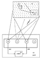
図1は、基地局100が、異なる視点からシーン104の画像をキャプチャするステレオ(例えば赤外)カメラ102及び103を含む一実装を例示している。プロジェクタ106は、光パターン(例えば約100,000ポイント)でシーン104を照らす。光パターンは疑似乱数であってもよく、回折光素子を通してレーザ光を放射することにより生成され得る。代わりに線パターンや他の形状のスポット等が生成され、感知されることもあるが、簡潔性の目的で、本明細書では、放射されたパターンのポイント/コンポーネントを一般的にドットと称する。
FIG. 1 illustrates one implementation in which
カメラ102及び103は、シーン222及び(場合によっては)背景内の物体面からドットが反射されると、これらのドットをキャプチャする。一般に一方のカメラ(例えば102)によって感知されるドットは、画像処理108(例えばシステム又はサブシステム)を介して他のカメラ(例えば103)によって感知されるドットと相関され、これにより、各ドットが入射した反射面までの距離を(例えば三角測量により)提供することができる。図1は、いずれかのサイズ、距離、ドットの分散パターン、ドットの密度についてスケーリングするよう意図されておらず、またこれらを示すようにも意図されていないことに留意されたい。
また、基地局100は、クリーンなIRカメラ、例えば能動照明パターンをブロックするフィルタを有するIRカメラ及び/又は可視光をキャプチャするRGBカメラを含むこともあり、その双方が存在する場合は、これらのカメラを単一のカメラに組み合わせてもよい。図1のカメラ112は、これらの代替的なカメラのうちのいずれかを表す。
The
図1に示されるように、シーン104内で感知される対象物の1つは、モバイルのスマートフォン又はタブレットコンピューティングデバイスといった、衛星デバイス110であり得る。同時に、衛星デバイスは、例えばその深度を含め、シーン内の他の対象物を感知していることがあり、これは、例えば照明パターンを感知し、場合によっては、そのクリーンIR及び/又はRGB画像を感知するステレオIRカメラ等を介して行われる。
As shown in FIG. 1, one of the objects sensed in the
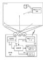
図2は、例示の基地局100を示しており、基地局100内では、画像キャプチャシステム又はサブシステム224のステレオカメラ102及び103が、時間で同期される画像をキャプチャする(例えばこれらのカメラは“ゲンロック(genlocked)”される)。一実装において、カメラは赤外(IR)画像をキャプチャするが、これは、IRがシーンの視覚的外観に影響しないためである(このことは、例えばビデオ会議やオブジェクトモデル化アプリケーションにおいて非常に有利である)。容易に認識されるように、スタジオ環境のような一部のシナリオでは、2つより多くのIR深度感知カメラが存在してもよい。さらに、RGBカメラのような1つ以上の他のカメラが、所与のシステム内に存在してもよく、そのような他のカメラを使用して、例えば画像を整列させ、異なるステレオ画像内のドットのペアを相関させること等を助けることができる。
FIG. 2 shows an
図2では、プロジェクタ106は、IRパターンをシーン上に投影する。シーンを比較的多数の分散赤外ドットで照らすことにより、カメラ102及び103は、更なるテクスチャデータを赤外画像データの一部としてキャプチャすることができる。プロジェクタ106の配置は、カメラの外側(例えば図2)であっても、カメラの間(例えば図1)であってもよく、あるいは、双方の又は一方のカメラの上又は下のような別の位置であってもよいことに留意されたい。この説明における例は、カメラ102、103及び/又はプロジェクタ106が互いに対して配置される場所を限定するものではなく、カメラを、互いに対して異なる位置に配置してよい。
In FIG. 2, the
一実装において、例示の画像キャプチャシステム又はサブシステム224は、カメラインタフェース230を介してカメラ102及び103の動作を制御し、存在する場合にはカメラ112の動作も制御するコントローラ228を含む。例示されるコントローラは、プロジェクタインタフェース232を介してプロジェクタ106の動作も制御する。例えばカメラ102及び103は、例えば1つのコントローラの信号(あるいはカメラ毎に異なる信号)等によって、ステレオ画像を同時にキャプチャするように同期(ゲンロック)される。プロジェクタ106は、例えばターンオン又はターンオフされるか、パルス化されるか、そうでなくとも制御可能に変化する1つ以上のパラメータを有することがある。
In one implementation, the example image capture system or
カメラ102及び103(存在する場合は、更にカメラ112)によってキャプチャされる画像は、ハードウェア及び/又はソフトウェアで(例えばコンピュータ読取可能命令として)実装されるロジックを備える画像処理108システム又はサブシステムに提供される。一部の実装では、画像処理システム108と画像キャプチャシステム又はサブシステム224を、あるいはこれらの一部を組み合わせて、単一のデバイスにしてもよい。例えばホームエンターテイメントデバイスが、図1に示されるコンポーネント(並びに図示されないコンポーネント)の全てを含んでもよい。他の実装では、カメラ及びプロジェクタといった、画像キャプチャシステム又はサブシステム224の一部(又は全て)が、ゲームコンソール、パーソナルコンピュータ、衛星デバイス、専用の処理デバイス及び/又は同様のものに結合する別個のデバイスであってもよい。
Images captured by
1つ以上の実装において、画像処理システム又はサブシステム108は、プロセッサ240と、1つ以上の画像処理アルゴリズム244を含むメモリ242とを含む。1つ以上の深度マップ246は、アルゴリズム124により、例えば合致する(ドット及び/又は線といった)特徴を抽出すること等によって取得され得る。例えば既知であるように、例えば米国特許出願公開第2013/0,100,256号で説明されるように、異なるドット又は他の投影される素子は、キャプチャされるとき、プロジェクタから反射面までの距離及び/又はカメラから反射面までの距離に応じて、強度(明度)を含め異なる特徴を有する。これもまた知られているように、(例えばゲンロックされるステレオカメラにより)同時に撮られた異なる画像内のドットは、同じ瞬間にキャプチャされた同じシーンのRGB画像の間の小さい(例えばRGB)パッチを合致させること等により、相互に相関され得る。したがって、キャプチャされた画像により、既知のアルゴリズムは、深度を決定するために合致したドット間の特定の特徴の三角測量/差異を使用して、各画像内の投影された光コンポーネント(例えばドット)を合致させることにより、個々の深度に関連する特徴(深度マップ)を決定することができる。これは、ステレオ画像処理を介して深度マップを取得し得る1つの方法である。
In one or more implementations, the image processing system or
また、図1には、基地局への1つ以上のインタフェース、例えば深度マップを用いるアプリケーション等と対話をするのにユーザにとって適切であるように、キーボード、ゲームコントローラ、ディスプレイ、音声コマンドのためのポインティングデバイスマイクロフォン及び/又は同様のものを接続するためのインタフェースが示されている。少なくとも1つのインタフェース132は、衛星デバイス110が、本明細書で説明されるように基地局と(例えば無線で)通信するのを可能にする。
Also shown in FIG. 1 is a keyboard, game controller, display, voice command, as appropriate for the user to interact with one or more interfaces to the base station, such as an application using a depth map. An interface for connecting a pointing device microphone and / or the like is shown. The at least one
1つ以上の実装は、レーザーパターンを放射して深度を計算する、室内の基地局100を備える。ユーザが、スマートフォンやタブレットといった衛星デバイス110を使用するとき、衛星デバイス110上のカメラ又はステレオカメラは、ベースユニット(基地局)の放射レーザーパターンを観察することができる。衛星デバイス110は、したがって、その外部生成されたレーザーパターンに基づいて、ステレオを計算し、さらに、情報を基地局100に通信することができる。
One or more implementations include an
本明細書で説明されるように、衛星デバイスのデータを使用して、基地局が計算することができる解像度よりも、高い解像度で深度マップを生成することができる(本明細書で使用されるとき、「高解像度」は、カメラ自体の解像度を指してはおらず、衛星デバイスが対象物、例えばユーザの顔により近いために、基地局上の遠くにあるカメラよりも多くのピクセルで対象物をキャプチャすることができる能力を指していることに留意されたい)。さらに、空間的解像度が向上するだけでなく、深度解像度/精度も向上し得る。画像情報又は情報に対応するデータ(例えば衛星デバイスで計算される深度マップ)がベースユニットに伝送されることがある。本明細書で使用されるとき、「画像関連のデータ」とは、(全体又は部分的に、1つ以上のIR及び/RGBの能動的に照明される画像及び/又はクリーンIR及び/又はRGB画像の)実際の画像データ、任意の関連付けられるメタデータ及び/又は例えば深度マップのような画像データから処理される任意の対応する情報を指す。したがって、画像関連のデータは、基地局へ及び基地局から、そして衛星デバイスへ及び衛星デバイスから通信され得る。 As described herein, satellite device data can be used to generate a depth map at a higher resolution than can be calculated by the base station (as used herein). Sometimes, "high resolution" does not refer to the resolution of the camera itself, but because the satellite device is closer to the object, for example the user's face, the object is taken up with more pixels than a camera far away on the base station. Note that this refers to the ability to capture). Furthermore, not only the spatial resolution is improved, but also the depth resolution / accuracy can be improved. Image information or data corresponding to the information (eg, a depth map calculated by a satellite device) may be transmitted to the base unit. As used herein, “image related data” means (in whole or in part, one or more IR and / or RGB actively illuminated images and / or clean IR and / or RGB Refers to the actual image data (of the image), any associated metadata and / or any corresponding information processed from the image data, eg, a depth map. Thus, image-related data can be communicated to and from the base station and to and from the satellite device.
加えて、衛星デバイス及びベースユニットで撮られた画像及び/又は深度マップを相関させることができる。これは、ベースユニットに対するモバイルユニットの位置のポーズ推定に対して、6つの自由度(6DoF)を提供する。 In addition, images and / or depth maps taken with satellite devices and base units can be correlated. This provides 6 degrees of freedom (6 DoF) for pose estimation of the position of the mobile unit relative to the base unit.
ポーズ推定は、画像整列によって、かつ/又はパターンマッチング/ドット相関により決定され得る。例として、衛星デバイスが、基地局も感知することができる(例えばユーザ又はデバイスが、同じエリアを基地局が「見る」ことをブロックしていない)画像をキャプチャする場合、ピクセル(又は各ピクセルの対応する周囲のパッチ)を既知の方法で合致させることができる。基地局から計算される深度データを、衛星デバイスから計算される深度データと整列させることによって、整列を確立することもできる。したがって、衛星デバイスのポーズが推定され得る。 Pose estimation can be determined by image alignment and / or by pattern matching / dot correlation. As an example, if the satellite device captures an image that can also be sensed by the base station (eg, the user or device is not blocking the base station from “seeing” the same area), the pixel (or for each pixel) Corresponding surrounding patches) can be matched in a known manner. Alignment can also be established by aligning the depth data calculated from the base station with the depth data calculated from the satellite device. Thus, the pose of the satellite device can be estimated.
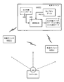
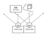
これは、一般的に図3に示されており、図3では、基地局300はプロジェクタ306からの光パターンを投影し、この光パターンが、基地局のカメラ301及び203によって、並びに衛星デバイス330(2つ以上の衛星デバイスが存在することもある)上の1つ以上のカメラによって感知される。カメラ301及び302は、衛星デバイスデータ334とともに画像処理に供給される基地局画像332を提供する。衛星デバイスデータ334は、各衛星デバイスにおいて画像からローカルで処理される深度マップのような画像又は情報であり得る。
This is generally illustrated in FIG. 3, where the
デバイス330からの破線により示されるように、オプションの(例えば低電力の)プロジェクタが、1つ以上の衛星デバイスのいずれか又は全てに含まれてもよい。衛星デバイスによって投影されるデータは、基地局から投影されるデータを強調する。衛星デバイス330内のプロジェクタは、距離的に制限され、空間的に制限され(例えば非常にまばらなパターンであるか、小さな画像領域のみでフォーカスされる)及び/又は時間的に制限される(例えば数フレームごとのみ放射される)ために、低電力であり得る。
As indicated by the dashed line from
基地局画像332は、衛星デバイス330のポーズ/3D位置を決定するのに処理され得る。この情報により、画像処理308は深度データ336を出力する。深度データ336は、衛星デバイスデータ334によって強化される、基地局自体のカメラからの従来的な深度データであってよい。一般に、基地局カメラによってキャプチャされる投影ドットは、解像度の差に起因するサイズの差等を調整した後、衛星デバイスによってキャプチャされるドットと相関され得る。ポーズデータ338は、例えば他の衛星デバイスへ出力されることもある。
衛星デバイスが、基地局に、その画像データを強化するためのデータを提供する代わりに、基地局が、(デバイスのポーズとともに)近似深度マップを衛星デバイスに送信してもよいことに留意されたい。これは、正確性を向上させ、かつ/又は衛星デバイス自体の深度推定のために必要とされる計算を低減させるのに使用され得る。 Note that instead of the satellite device providing the base station with data to enhance its image data, the base station may send an approximate depth map (with device pose) to the satellite device. . This can be used to improve accuracy and / or reduce the computation required for depth estimation of the satellite device itself.
基地局の深度マップ(並びにRGBデータ)は、高解像度のデータを部分的な深度マップへとダウンサンプリングすることによって強化され得る。部分的な深度マップは、適切な座標において初期の基地局の深度マップと結合され、例えばポーズについて深度を調整した後、これらの座標における精度が改善され得る。基地局の深度マップを強化し得る別の方法は、例えば元の深度マップを、より高解像度の深度マップと関連付けて(例えばポーズに基づいて深度を調整した後に)保持することである。このようにして、深度マップを使用するアプリケーションは、望むときに、より精細な粒度の深度データに「ズームイン」することができ、例えばアプリケーションは、元の深度マップのピクセル解像度に制限される必要がない。 The base station depth map (as well as RGB data) can be enhanced by down-sampling the high resolution data into a partial depth map. The partial depth map may be combined with the initial base station depth map at the appropriate coordinates to improve accuracy at these coordinates, for example after adjusting the depth for the pose. Another way that the depth map of the base station can be enhanced is, for example, to keep the original depth map associated with a higher resolution depth map (eg, after adjusting the depth based on the pose). In this way, applications that use depth maps can “zoom in” to finer granularity depth data when desired, for example, applications need to be limited to the pixel resolution of the original depth map. Absent.
幾つかのモバイルデバイスは、正面及び背面のカメラを有することに留意されたい。そのような場合、あるシナリオではカメラを異なる目的で使用することになる。例えば背面カメラを使用してポーズ計算のための画像をキャプチャし、一方、正面カメラが、ユーザの顔の画像、例えば強化される深度計算に使用され得る画像をキャプチャしてもよい。 Note that some mobile devices have front and back cameras. In such a case, the camera will be used for different purposes in some scenarios. For example, a rear camera may be used to capture an image for pose calculation, while a front camera may capture an image of the user's face, for example an image that can be used for enhanced depth calculation.
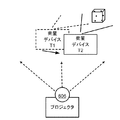
図4は、別の代替形態を示しており、図4では、複数の衛星デバイス440(1)〜440(n)がピアとして動作し、したがって、基地局を必要とせずに、シーンについての深度情報を計算することができる。しかしながら、衛星デバイスは電池式なので、1つの(又は2つ以上の)外部プロジェクタ406からの光パターンが利用され得る。基地局は、基本的に、一般的にはモバイルでないことを除いて、単に別のデバイスであることに留意されたい(基地局は、比較的コンパクトでポータブルであるが、大きな又は固定式の電源を使用するので、タブレットデバイスやスマートフォンとは異なり、典型的には持ち運びされない)。
FIG. 4 shows another alternative, in which multiple satellite devices 440 (1) -440 (n) operate as peers, and thus do not require a base station, and depth for the scene. Information can be calculated. However, since satellite devices are battery powered, light patterns from one (or more)
図4に示されるように、衛星デバイス440(1)〜440(n)の各々は、そのデータを相互に交換する。デバイス440(2)のうちの1つが、画像処理408を有するように示されており、画像処理408は、デバイス440(2)自身の画像データ442及び他の衛星デバイスのデータ444を処理して、1つ以上の他の衛星デバイスのデータによって強化される深度データ446を取得する。理解されるように、任意の衛星デバイスが、同様の画像処理能力を有してもよく、かつ/又は別の衛星デバイスから深度データを受け取ってもよい。
As shown in FIG. 4, each of the satellite devices 440 (1) -440 (n) exchanges their data with each other. One of the devices 440 (2) is shown as having image processing 408, which processes the
別の態様として、図5は、例えば赤外光を介して基地局500に識別子をフラッシュするなどして、信号を提供するように構成される衛星デバイス550及び552を示している。識別子は、デバイスのタイプ、能力等を含め、任意のタイプの情報を含むか、このような任意のタイプの情報をルックアップするのに使用され得る。信号は、衛星デバイスのポーズをより効果的に決定する際の助けにもなり得る。
As another aspect, FIG. 5 shows
基地局が衛星デバイスを識別し、かつ/又はそのポーズを推定する代わりに、衛星デバイスが基地局を識別し、その情報に基づいて、自身のポーズを推定してもよいことに留意されたい。これは、衛星デバイスが、基地局と通信する必要なくそのポーズを決定することを可能にし、これは一部の状況(例えば比較的多くの数の衛星デバイスが存在する場合)に有益なものとなり得る。 Note that instead of the base station identifying the satellite device and / or estimating its pose, the satellite device may identify the base station and estimate its pose based on that information. This allows the satellite device to determine its pose without having to communicate with the base station, which can be beneficial in some situations (eg when there is a relatively large number of satellite devices). obtain.
別の態様として、図6Aは、時間とともに動く衛星デバイスが、単一のカメラで深度データをどのように計算することができるかについて示している。ドットは動かないので、デバイスのいずれかの動きが、ドットの位置を、カメラの以前の視点から新たな視点へと変化させる。 As another aspect, FIG. 6A shows how a satellite device moving over time can calculate depth data with a single camera. Since the dots do not move, any movement of the device changes the position of the dots from the camera's previous viewpoint to the new viewpoint.
図6Bは、衛星モバイルデバイス上の1つのカメラによって感知される、2つのプロジェクタ606及び607を示している。投影されるパターンは異なり、これにより、衛星デバイスは一方のソースを別のソースから区別することができ、あるいは、これらのプロジェクタは交互に入れ替わって、一度に1つのプロジェクタが、感知されている同じ対象物/シーンの2つの異なる視点を提供するように投影することができる。
FIG. 6B shows two
実際、プロジェクタが、光パターンの知識を有することがあり、そのような場合は基本的に、反対に、カメラである。したがって、単一のプロジェクタと単一の衛星デバイスカメラを使用して、ステレオ深度データを計算することができる。 In fact, the projector may have knowledge of the light pattern, in which case it is basically the camera, on the contrary. Accordingly, stereo depth data can be calculated using a single projector and a single satellite device camera.
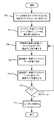
図7は、衛星デバイスを介して、強化された深度情報(及び場合によっては、RGB画像のような他の情報)を取得するのに行われ得るステップの例示のセットを表す、簡略化されたフロー図である。例えば基地局上で実行されるか、基地局に結合されるアプリケーションプログラムが、基地局から比較的離れており、かつ近くに移動するのが特に容易ではないか望ましくない対象物についての詳細なクローズアップ表現を生成することを望むという状況を考える。以下では、例示のステップにおいて基地局について説明するが、理解されるように、基地局の代わりに、別のモバイルデバイス又はデバイスのセットを使用してもよい。 FIG. 7 is a simplified representation representing an exemplary set of steps that may be taken to obtain enhanced depth information (and possibly other information such as RGB images) via a satellite device. FIG. For example, an application program that runs on or is coupled to a base station that is relatively remote from the base station and detailed close-up on objects that are not particularly easy or desirable to move nearby Consider a situation where one wants to generate an up representation. In the following, the base station will be described in an exemplary step, but as will be appreciated, another mobile device or set of devices may be used in place of the base station.
ステップ702において、基地局のプログラム(又はこれに結合されるプログラム)が、ユーザに、一部のクローズアップビデオフレームを取得するために衛星デバイスを対象物に向けるようにユーザに指示するメッセージを通信する。ステップ704において、ユーザがそのようにすると、これにより衛星デバイスは、基地局へのデータ(例えば画像のストリーム又はそれから処理されるべき深度データ)の伝送を開始する。各フレームでは、ステップ706において、基地局は、基地局自体のキャプチャされた画像を処理して、衛星カメラのポーズを決定し、初期の深度マップを計算する。
In
ステップ708は、衛星デバイスからデータを受け取ることを表しているが、これらのステップの少なくとも一部は、並行に及び/又は異なる順序で生じてもよく、例えば基地局の処理の前に、処理の間に又は処理の後に、データの一部又は全てが衛星デバイスから受け取られることがあることに留意されたい。さらに、アプリケーションに応じて、フレームごとではなく、より低速のサンプリングレートが使用されてもよいことにも留意されたい。 Step 708 represents receiving data from the satellite device, but at least some of these steps may occur in parallel and / or in a different order, e.g., before processing of the base station. Note that during or after processing, some or all of the data may be received from the satellite device. It should also be noted that slower sampling rates may be used rather than frame by frame, depending on the application.
ステップ710は、衛星データを使用して、例えばより正確な深度データで深度マップを強化し、かつ/又はキャプチャされた対象物について別個の深度マップを保持することを表す。ステップ712は、ユーザに通知されるときまで、処理を繰り返す。 Step 710 represents using satellite data to enhance the depth map, eg, with more accurate depth data, and / or maintaining a separate depth map for the captured object. Step 712 repeats the process until notified to the user.
ユーザは、異なる方向から対象物のビデオをキャプチャするように要求され得る。投影された光が衛星デバイスによって感知されている場合、ユーザは、対象物の異なる部分が異なる時間にプロジェクタに面するように対象物を回転させるよう指示され得る(ユーザは、赤外光のパターンを見ることはできないので、これが投影されていることを知らないことがあり、このため、その指示が、基地局デバイスに面するように対象物を回転させるようにし得ることに留意されたい)。あるいは、異なる方向からの複数のプロジェクタが存在してもよい。このようにして、基地局がキャプチャすることができるレベルよりも非常に高い詳細レベルで、対象物についての完全な3次元のメッシュ又は同様のものが生成され得る(RGB画像データがこれと組み合わされてもよい)。 The user may be requested to capture the video of the object from different directions. If the projected light is being sensed by the satellite device, the user can be instructed to rotate the object so that different parts of the object face the projector at different times (the user can see the pattern of infrared light (Note that it may not know that this is being projected, so the indication may cause the object to rotate to face the base station device). Alternatively, there may be a plurality of projectors from different directions. In this way, a complete three-dimensional mesh or the like for the object can be generated with a level of detail much higher than the level that the base station can capture (RGB image data is combined with this). May be).
衛星デバイス及び基地局(又は他のモバイルデバイス)は、人の介入なしに一緒に動作することがある。例えばモバイルデバイスアプリケーションは、デバイスカメラを介して興味ある何かを検出し、画像データを基地局に通信することがある。周期的又は何らかの他のスケジュールで、基地局は、衛星デバイスに1つ以上の画像を要求することがある。基地局は(例えばアプリケーションプログラムによって指示されるように)、(ポーズデータを介して知られるような)衛星デバイスのカメラが向いている何らかの物について改善された画像を持ちたいことがある。例えばこれにより、望むときはいつでも、より高解像度の画像を取得できることになる。 Satellite devices and base stations (or other mobile devices) may work together without human intervention. For example, a mobile device application may detect something of interest via a device camera and communicate image data to a base station. Periodically or on some other schedule, the base station may request one or more images from the satellite device. The base station may want to have an improved image of anything the satellite device's camera is facing (such as known via pause data) (eg, as directed by the application program). For example, this will allow higher resolution images to be acquired whenever desired.
別の例として、衛星デバイスからのデータを使用して、1つ又は複数の衛星デバイスがキャプチャした画像内のデータを置き換えてもよい。具体的な例として、何かがシーンの所望の部分を基地局の視点からブロックしていること、例えば衛星デバイスがキャプチャしようとしているシーン内の興味ある部分の前を人が歩いていることを考える。衛星デバイス又は衛星デバイスのセットを用いてシーンを(異なるアングルから、そして場合によっては異なる解像度で)キャプチャし、これにより、人がシーンのその部分をブロックしていないかのように、シーンの深度(及びRGB若しくはクリーンIRデータ)を再計算することができる。 As another example, data from satellite devices may be used to replace data in images captured by one or more satellite devices. A specific example is that something is blocking the desired part of the scene from the base station's point of view, for example a person walking in front of the part of the scene that the satellite device is trying to capture. Think. Capture the scene with a satellite device or set of satellite devices (from different angles and possibly at different resolutions) so that the depth of the scene as if a person is not blocking that part of the scene (And RGB or clean IR data) can be recalculated.
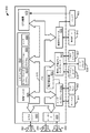
<例示の動作環境>
図8は、本明細書で説明される主題の態様が実装され得る適切なモバイルデバイス800の例を図示している。モバイルデバイス800は、デバイスの単なる一例であり、本明細書で説明される主題の態様の使用又は機能の範囲に関して何らかの限定を示唆するようには意図されていない。また、モバイルデバイス800は、例示のモバイルデバイス800内に図示されるコンポーネントのいずれか1つ又は組合せに関して、何らかの依存性又は要件を有するものとして解釈されるべきでもない。
<Example operating environment>
FIG. 8 illustrates an example of a suitable
図8を参照すると、本明細書で説明される主題の諸態様を実装するための例示のデバイスは、モバイルデバイス800を含む。一部の実施形態において、モバイルデバイス800は、携帯電話、他者への音声通信を可能にするハンドヘルドデバイス又は何らかの他の音声通信デバイス等を備える。これらの実施形態では、モバイルデバイス800に、写真を撮るためのカメラを搭載することができるが、他の実施形態ではこれは必ずしも必要とされない。他の実施形態では、モバイルデバイス800は、パーソナルデジタルアシスタント(PDA)、ハンドヘルドゲームデバイス、ノートブックコンピュータ、プリンタ、セットトップを含む機器、メディアセンター又は他の機器又は他のモバイルデバイス等を備えてもよい。更に他の実施形態では、モバイルデバイス800は、パーソナルコンピュータやサーバ等といった一般的には非モバイルと考えられるデバイスを備えてもよい。
With reference to FIG. 8, an exemplary device for implementing aspects of the subject matter described in this specification includes a
モバイルデバイスは、リモートコントロールにデータを入力する方法とともに制御ロジックを提供する追加の回路を有する、機器又は玩具のハンドヘルド型のリモートコントロールを備えてもよい。例えば入力ジャック又は他のデータ受信センサは、デバイスが、非制御コードデータ伝送のために目的変更されることを可能にする。これは、伝送すべきデータの多くを格納する必要なく達成されることがあり、例えばデバイスは、スマートフォンのような(場合によっては幾らかのバッファリングを伴う)別のデバイスへのデータ中継として機能し得る。 The mobile device may comprise a handheld remote control of the device or toy with additional circuitry that provides control logic along with a method for entering data into the remote control. For example, an input jack or other data receiving sensor allows the device to be repurposed for non-control code data transmission. This may be achieved without having to store much of the data to be transmitted, for example the device acts as a data relay to another device (possibly with some buffering) such as a smartphone Can do.
モバイルデバイス800のコンポーネントには、これらに限られないが、処理ユニット805と、システムメモリ810と、システムメモリ810を含め、様々なシステムコンポーネントを処理ユニット805に結合するバス815が含まれ得る。バス815は、様々なバスアーキテクチャのいずれかを使用するメモリバス、メモリコントローラ、周辺バス及びローカルバス等を含め、幾つかのタイプのバス構造のうちのいずれかを含み得る。バス815は、モバイルデバイス800の様々なコンポーネント間でデータが伝送されるのを可能にする。
The components of
モバイルデバイス800は、様々なコンピュータ読取可能媒体を含み得る。コンピュータ読取可能媒体は、モバイルデバイス800によりアクセスすることができる任意の利用可能な媒体とすることができ、揮発性及び不揮発性媒体と、取外し可能及び取外し不可能媒体の双方を含む。限定ではなく例として、コンピュータ読取可能媒体は、コンピュータ記憶媒体と通信媒体を備えることがある。コンピュータ記憶媒体は、コンピュータ読取可能命令、データ構造、プログラムモジュール又は他のデータといった、情報の記憶のための任意の方法又は技術で実装される揮発性及び不揮発性、取外し可能及び取外し不可能媒体を含む。コンピュータ記憶媒体は、これらに限られないが、RAM、ROM、EEPROM、フラッシュメモリ又は他のメモリ技術、CD−ROM、デジタル多用途ディスク(DVD)又は他の光ディスクストレージ、磁気カセット、磁気テープ、磁気ディスクストレージ又は他の磁気記憶デバイス、あるいは所望の情報を格納するのに使用することができ、かつモバイルデバイス800によりアクセス可能な任意の他の媒体を含む。
通信媒体は、典型的に、コンピュータ読取可能命令、データ構造、プログラムモジュール又は他のデータを、搬送波や他の伝送機構といった変調データ信号に具現化し、任意の情報伝達媒体を含む。「変調データ信号」という用語は、信号内に情報を符号化するような手法で設定又は変更された特性の1つ以上を有する信号を意味する。限定ではなく例として、通信媒体は、有線ネットワークや直接有線接続といった有線媒体と、音響、RF、Bluetooth(登録商標)、無線USB、赤外線、Wi-Fi、WiMAX及び他の無線媒体といった無線媒体とを含む。上記の任意の組合せもコンピュータ読取可能媒体の範囲内に含まれるべきである。 Communication media typically embodies computer readable instructions, data structures, program modules or other data in a modulated data signal such as a carrier wave or other transport mechanism and includes any information delivery media. The term “modulated data signal” means a signal that has one or more of its characteristics set or changed in such a manner as to encode information in the signal. By way of example, and not limitation, communication media includes wired media such as a wired network and direct-wired connection, and wireless media such as acoustic, RF, Bluetooth, wireless USB, infrared, Wi-Fi, WiMAX, and other wireless media. including. Any combination of the above should also be included within the scope of computer-readable media.
システムメモリ810は、揮発性及び/又は不揮発性メモリの形式のコンピュータ記憶媒体を含み、読取専用メモリ(ROM)及びランダムアクセスメモリ(RAM)を含むこともある。携帯電話のようなモバイルデバイスでは、時々、オペレーティングシステムコード820がROMに含まれるが、他の実施形態ではこれは必要とされない。同様に、アプリケーションプログラム825はしばしばRAMに配置されるが、やはり、他の実施形態では、アプリケーションプログラムは、ROM又は他のコンピュータ読取可能メモリに配置されてよい。ヒープ830は、オペレーティングシステム820及びアプリケーションプログラム825に関連付けられる状態をメモリに提供する。例えばオペレーティングシステム820及びアプリケーションプログラム825は、変数及びデータ構造を、これらの動作中にヒープ830内に格納し得る。
The
モバイルデバイス800は、他の取外し可能/取外し不可能、揮発性/不揮発性メモリを含んでもよい。例として、図8は、フラッシュカード835、ハードディスクドライブ836及びメモリスティック837を図示している。ハードディスクドライブ836は、例えばメモリスロットにフィットするよう小型化され得る。モバイルデバイス800は、取外し可能メモリインタフェース831を介して、これらのタイプの不揮発性の取外し可能媒体とインタフェースしてよく、あるいはユニバーサルシリアルバス(USB)、IEEE8394、有線ポート840のうちの1つ以上又はアンテナ865を介して接続され得る。これらの実施形態では、取外し不可能なメモリデバイス835〜837は、通信モジュール832を介してモバイルデバイスとインタフェースし得る。一部の実施形態では、これらのタイプのメモリの必ずしも全てが単一のモバイルデバイスに含まれなくてもよい。他の実施形態では、これら及び他のタイプの取外し可能メモリのうちの1つ以上が、単一のモバイルデバイスに含まれ得る。
The
一部の実施形態において、ハードディスクドライブ836は、モバイルデバイス800により恒久的に取り付けられるような方法で接続され得る。例えばハードディスクドライブ836は、パラレルATA(PATA)、シリアルATA(SATA)又は他の方法デバイス815に接続され得るインタフェースへ接続される。そのような実施形態では、ハードドライブを取り外すことは、モバイルデバイス800のカバーを取外し、ハードドライブ836をモバイルデバイス800内の支持構造に接続するネジ又は他の留め具を取り外すことを要することがある。
In some embodiments, the
上述及び図8に図示される取外し可能なメモリデバイス835〜837及びその関連するコンピュータ記憶媒体は、コンピュータ読取可能命令、プログラムモジュール、データ構造及びモバイルデバイス800のための他のデータのストレージを提供する。例えば1つ以上の取外しメモリデバイス835〜837は、モバイルデバイス800が撮った画像、音声記録、連絡先情報、プログラム、プログラム用のデータ等を格納することがある。
The removable memory devices 835-837 and their associated computer storage media described above and illustrated in FIG. 8 provide storage of computer readable instructions, program modules, data structures and other data for the
ユーザは、コマンド及び情報を、キーパッド841及びマイクロフォン842といった入力デバイスを介してモバイルデバイス800に入力することができる。一部の実施形態では、ディスプレイ843は、タッチセンサ式画面であってよく、ユーザがその上にコマンド及び情報を入力するのを可能にすることができる。キーパッド841及びディスプレイ843は、バス815に結合されるユーザ入力インタフェース850を介して処理ユニット805に接続され得るが、通信モジュール832及び有線ポート840といった他のインタフェース及びバス構造によって接続されてもよい。動き検出852を使用して、デバイス800を用いて行われたジェスチャを決定することができる。
A user may enter commands and information into the
ユーザは、例えばマイクロフォン842に話すことにより、そしてキーパッド841又はタッチセンサ式のディスプレイ843上に入力されるテキストメッセージにより、他のユーザと通信してもよい。オーディオユニット855は、スピーカ844を駆動する電子信号を提供し、そしてマイクロフォン842からオーディオ信号を受け取り、受け取ったオーディオ信号をデジタル化することができる。
A user may communicate with other users, for example, by speaking to the
モバイルデバイス800は、カメラ861を駆動する信号を提供するビデオユニット860を含んでもよい。ビデオユニット860は、カメラ861によって取得された画像を受け取ることもあり、これらの画像を処理ユニット805及び/又はモバイルデバイス800に含まれるメモリに提供することがある。カメラ861によって取得される画像は、ビデオ、ビデオを形成しない1つ以上の画像又はこれらの何らかの組合せを備え得る。
通信モジュール832は、1つ以上のアンテナ865に信号を提供し、1つ以上のアンテナ865から信号を受け取ることがある。アンテナ865のうちの1つが、携帯電話ネットワークのためのメッセージを送受信し得る。別のアンテナはBluetooth(登録商標)のメッセージを送受信し得る。更に別のアンテナ(又は共有アンテナ)は、無線のEthernet(登録商標)のネットワーク規格を介してネットワークねっセージを送受信し得る。
またさらに、アンテナは、位置ベースの情報、例えばGPS信号をGPSインタフェース及び機構872に提供する。次いで、GPS機構872は、対応するGPSデータ(例えば時間と座標)を処理に利用可能にする。
Still further, the antenna provides position-based information, eg, GPS signals, to the GPS interface and
一部の実施形態では、単一のアンテナが、1つより多くのタイプのネットワークのためのメッセージを送信及び/又は受信するのに使用され得る。例えば単一のアンテナが音声及びパケットメッセージを送受信し得る。 In some embodiments, a single antenna may be used to transmit and / or receive messages for more than one type of network. For example, a single antenna can send and receive voice and packet messages.
ネットワーク環境で操作されるとき、モバイルデバイス800は1つ以上のリモートデバイスに接続することがある。リモートデバイスは、パーソナルコンピュータ、サーバ、ルータ、ネットワークPC、携帯電話、メディア再生デバイス、ピアデバイス又は他の一般的なネットワークノードを含んでよく、典型的には、モバイルデバイス800に関連して上述したような要素の多く又は全てを含む。
When operated in a network environment, the
本明細書で説明される主題の態様は、多数の他の汎用又は専用のコンピューティングシステム環境又は構成で動作する。本明細書で説明される主題の態様とともに使用するのに適切であり得る周知のコンピューティングシステム、環境及び/又は構成の例には、これらに限られないが、パーソナルコンピュータ、サーバコンピュータ、ハンドヘルド又はラップトップデバイス、マルチプロセッサシステム、マルチコントローラベースのシステム、セットトップボックス、プログラマブル家庭用電化製品、ネットワークPC、ミニコンピュータ、メインフレームコンピュータ、上記のシステム若しくはデバイスのいずれかを含む分散コンピューティング環境及び同様のものが含まれる。 Aspects of the subject matter described in this specification operate in numerous other general purpose or special purpose computing system environments or configurations. Examples of well-known computing systems, environments and / or configurations that may be suitable for use with aspects of the subject matter described herein include, but are not limited to, personal computers, server computers, handhelds, or Laptop devices, multiprocessor systems, multi-controller based systems, set top boxes, programmable consumer electronics, network PCs, minicomputers, mainframe computers, distributed computing environments including any of the above systems or devices, and the like Is included.
本明細書で説明される主題の態様は、プログラムモジュールのように、モバイルデバイスによって実行されるコンピュータ実行可能命令の一般的なコンテキストで説明され得る。一般に、プログラムモジュールは、特定のタスクを実行するか特定の抽象データタイプを実装するルーチン、プログラム、オブジェクト、コンポーネント、データ構造等を含む。本明細書で説明される主題の態様は、通信ネットワークを介してリンクされるリモート処理デバイスによってタスクが実行される、分散コンピューティング環境においても実施され得る。分散コンピューティング環境において、プログラムモジュールは、メモリ記憶デバイスを含め、ローカルとリモートの記憶媒体の双方に配置されてもよい。 Aspects of the subject matter described in this specification can be described in the general context of computer-executable instructions, such as program modules, being executed by mobile devices. Generally, program modules include routines, programs, objects, components, data structures, etc. that perform particular tasks or implement particular abstract data types. Aspects of the subject matter described in this specification can also be practiced in distributed computing environments where tasks are performed by remote processing devices that are linked through a communications network. In a distributed computing environment, program modules may be located in both local and remote storage media including memory storage devices.
さらに、本明細書ではサーバという用語が使用され得るが、この用語は、クライアント、1つ以上のコンピュータ上で分散される1つ以上のプロセスのセット、1つ以上のスタンドアロンの記憶デバイス、1つ以上の他のデバイスのセット、上記のうちの1つ以上の組合せ等も含み得る。 Further, the term server may be used herein, which refers to a client, a set of one or more processes distributed on one or more computers, one or more stand-alone storage devices, one Other sets of devices, combinations of one or more of the above, and the like may also be included.
<結論>
本発明は、様々な修正及び代替的構成を許容するが、その特定の例示の実施形態を図面に示し、上記で詳細に説明してきた。しかしながら、本発明を、開示した特定の形式に限定するという意図はなく、反対に、全ての修正、代替的構成並びに本発明の精神及び範囲に入る均等物を網羅するよう意図されることを理解されたい。
<Conclusion>
While the invention is susceptible to various modifications and alternative constructions, certain exemplary embodiments thereof are shown in the drawings and have been described above in detail. It should be understood, however, that the intention is not to limit the invention to the particular form disclosed, but on the contrary is intended to cover all modifications, alternative constructions, and equivalents falling within the spirit and scope of the invention. I want to be.
Claims (8)
前記基地局によって、前記照明されたシーンの画像をキャプチャするステップと;
前記基地局によってキャプチャされた前記画像に基づいて、前記衛星デバイスのポーズ情報を決定し、前記画像に関連する深度データのセットを計算するステップと;
前記画像関連データ及び前記衛星デバイスのポーズ情報に少なくとも部分的に基づいて、前記深度データのセットを強化して深度データマップを計算するステップと;
を備える、方法。 Receiving image-related data from a satellite device at a base station, the image-related data comprising a scene illuminated by a light pattern projected from the base station , wherein the satellite device comprises the illuminated scene Within the steps;
Capturing an image of the illuminated scene by the base station;
Determining pose information for the satellite device based on the image captured by the base station and calculating a set of depth data associated with the image;
Enhancing the set of depth data and calculating a depth data map based at least in part on the image-related data and the pose information of the satellite device;
A method comprising:
請求項1に記載の方法。 Enhancing the set of depth data includes replacing at least a portion of the data in the set of depth data with other depth data corresponding to at least a portion of the image-related data.
The method of claim 1.
請求項1に記載の方法。 Enhancing the depth data set includes maintaining a first depth map corresponding to the depth data set in association with a second depth map corresponding to the image-related data.
The method of claim 1.
前記少なくとも一部の深度データは、前記画像関連データの少なくとも一部であり、
前記少なくとも一部の深度データは、前記衛星デバイスによってキャプチャされる、1つ以上の能動的に照明された画像を処理することによって計算されるか、前記衛星デバイスによってキャプチャされる1つ以上の能動的に照明されたステレオ画像及び前記衛星デバイスから放射される少なくとも一部の能動的照明を処理することによって計算される、
請求項1に記載の方法。 Receiving at least some depth data calculated at the satellite device based on at least one image captured by the satellite device;
The at least some depth data is at least part of the image-related data;
The at least some depth data is calculated by processing one or more actively illuminated images captured by the satellite device or one or more active data captured by the satellite device. Calculated by processing automatically illuminated stereo images and at least some active illumination emitted from the satellite device;
The method of claim 1.
当該基地局により、当該基地局から投影された光パターンによって照明されたシーンの1つ以上の画像をキャプチャし、
当該基地局によってキャプチャされた前記1つ以上の画像に基づいて、前記照明されたシーン内にある衛星デバイスのポーズ情報を決定し、前記1つ以上の画像に関連する深度データのセットを計算し、
前記衛星デバイスから前記照明されたシーンの画像関連データを受け取り、
前記衛星デバイスの前記ポーズ情報及び前記画像関連データに少なくとも部分的に基づいて、前記深度データのセットを強化して深度データマップを計算する
ように構成される、プロセッサ
を具備する、システム。 A system comprising a base station, wherein the base station is
Capturing one or more images of the scene illuminated by the light pattern projected from the base station by the base station ;
Based on the one or more images captured by the base station, determine pose information for satellite devices in the illuminated scene and calculate a set of depth data associated with the one or more images. ,
Receives the image-related data of the illuminated scene from the satellite device,
A system, comprising: a processor configured to enhance the set of depth data and calculate a depth data map based at least in part on the pose information and the image related data of the satellite device.
請求項5に記載のシステム。 The one or more images captured by the base station are actively illuminated image data;
The system according to claim 5.
請求項5に記載のシステム。 The satellite device is configured to calculate depth data and communicate the depth data to the base station as at least part of the image related data.
The system according to claim 5.
前記基地局において、衛星デバイスから画像関連データを受け取るステップであって、前記画像関連データが、前記基地局から投影された光パターンによって照明されたシーンを備え、前記衛星デバイスは、前記照明されたシーン内にある、ステップと;
前記基地局によって、前記照明されたシーンの画像をキャプチャするステップと;
前記基地局によってキャプチャされた前記画像に基づいて、前記衛星デバイスのポーズ情報を決定し、前記画像に関連する深度データのセットを計算するステップと、
前記画像関連データ及び前記衛星デバイスのポーズ情報に少なくとも部分的に基づいて、前記深度データのセットを強化して深度データマップを計算するステップと;
を含むステップを実行させる1つ以上のコンピュータプログラム。 Once executed, the base station processor
Receiving image-related data from a satellite device at the base station, the image-related data comprising a scene illuminated by a light pattern projected from the base station , the satellite device being the illuminated Steps in the scene ;
Capturing an image of the illuminated scene by the base station;
Determining pose information for the satellite device based on the image captured by the base station and calculating a set of depth data associated with the image;
Enhancing the set of depth data and calculating a depth data map based at least in part on the image-related data and the pose information of the satellite device;
One or more computer programs that cause the steps comprising:
Applications Claiming Priority (5)
| Application Number | Priority Date | Filing Date | Title |
|---|---|---|---|
| US201361812232P | 2013-04-15 | 2013-04-15 | |
| US61/812,232 | 2013-04-15 | ||
| US13/924,475 US9697424B2 (en) | 2013-04-15 | 2013-06-21 | Active stereo with satellite device or devices |
| US13/924,475 | 2013-06-21 | ||
| PCT/US2014/033919 WO2014172231A1 (en) | 2013-04-15 | 2014-04-14 | Active stereo with satellite device or devices |
Publications (3)
| Publication Number | Publication Date |
|---|---|
| JP2016522889A JP2016522889A (en) | 2016-08-04 |
| JP2016522889A5 JP2016522889A5 (en) | 2017-04-20 |
| JP6469080B2 true JP6469080B2 (en) | 2019-02-13 |
Family
ID=51686521
Family Applications (1)
| Application Number | Title | Priority Date | Filing Date |
|---|---|---|---|
| JP2016508993A Expired - Fee Related JP6469080B2 (en) | 2013-04-15 | 2014-04-14 | Active stereo with one or more satellite devices |
Country Status (11)
| Country | Link |
|---|---|
| US (14) | US20140307055A1 (en) |
| EP (9) | EP2987320B1 (en) |
| JP (1) | JP6469080B2 (en) |
| KR (2) | KR102130187B1 (en) |
| CN (8) | CN105229696A (en) |
| AU (1) | AU2014254219B2 (en) |
| BR (1) | BR112015025819A8 (en) |
| CA (1) | CA2907895C (en) |
| MX (1) | MX357307B (en) |
| RU (1) | RU2663329C2 (en) |
| WO (8) | WO2014172227A1 (en) |
Families Citing this family (204)
| Publication number | Priority date | Publication date | Assignee | Title |
|---|---|---|---|---|
| KR20120072245A (en) * | 2010-12-23 | 2012-07-03 | 한국전자통신연구원 | Apparatus and method for stereo matching |
| US9438813B2 (en) * | 2012-03-13 | 2016-09-06 | Dolby Laboratories Licensing Corporation | Lighting system and method for image and object enhancement |
| EP2700920B1 (en) | 2012-08-23 | 2016-06-22 | ams AG | Light sensor system and method for processing light sensor signals |
| US20140307055A1 (en) | 2013-04-15 | 2014-10-16 | Microsoft Corporation | Intensity-modulated light pattern for active stereo |
| US9467680B2 (en) | 2013-12-12 | 2016-10-11 | Intel Corporation | Calibration of a three-dimensional acquisition system |
| CN105829829B (en) * | 2013-12-27 | 2019-08-23 | 索尼公司 | Image processing device and image processing method |
| US9720506B2 (en) * | 2014-01-14 | 2017-08-01 | Microsoft Technology Licensing, Llc | 3D silhouette sensing system |
| CN105939837B (en) * | 2014-01-16 | 2019-05-10 | 惠普发展公司,有限责任合伙企业 | Processing slice data for additive manufacturing systems |
| US11265534B2 (en) * | 2014-02-08 | 2022-03-01 | Microsoft Technology Licensing, Llc | Environment-dependent active illumination for stereo matching |
| US9842424B2 (en) * | 2014-02-10 | 2017-12-12 | Pixar | Volume rendering using adaptive buckets |
| US20170078649A1 (en) | 2014-03-07 | 2017-03-16 | Brown University | Method and system for unsynchronized structured lighting |
| US20150266235A1 (en) * | 2014-03-19 | 2015-09-24 | Autodesk, Inc. | Systems and methods for improved 3d printing |
| US9674493B2 (en) * | 2014-03-24 | 2017-06-06 | Omnivision Technologies, Inc. | Color image sensor with metal mesh to detect infrared light |
| WO2015152829A1 (en) * | 2014-04-03 | 2015-10-08 | Heptagon Micro Optics Pte. Ltd. | Structured-stereo imaging assembly including separate imagers for different wavelengths |
| GB201407270D0 (en) * | 2014-04-24 | 2014-06-11 | Cathx Res Ltd | 3D data in underwater surveys |
| US9823842B2 (en) | 2014-05-12 | 2017-11-21 | The Research Foundation For The State University Of New York | Gang migration of virtual machines using cluster-wide deduplication |
| US9533449B2 (en) | 2014-06-19 | 2017-01-03 | Autodesk, Inc. | Material deposition systems with four or more axes |
| US10252466B2 (en) | 2014-07-28 | 2019-04-09 | Massachusetts Institute Of Technology | Systems and methods of machine vision assisted additive fabrication |
| CN106461378B (en) * | 2014-08-08 | 2019-10-25 | 塞姆布有限公司 | Vehicle equipment with scanning system for contactless measurement |
| US10455212B1 (en) * | 2014-08-25 | 2019-10-22 | X Development Llc | Projected pattern motion/vibration for depth sensing |
| JP6397698B2 (en) * | 2014-08-28 | 2018-09-26 | 任天堂株式会社 | Information processing terminal, information processing program, information processing terminal system, and information processing method |
| US9507995B2 (en) * | 2014-08-29 | 2016-11-29 | X Development Llc | Combination of stereo and structured-light processing |
| DE102014113389A1 (en) * | 2014-09-17 | 2016-03-17 | Pilz Gmbh & Co. Kg | Method and device for identifying structural elements of a projected structural pattern in camera images |
| CN107073827B (en) | 2014-09-26 | 2022-06-10 | 惠普发展公司有限责任合伙企业 | Illumination for additive manufacturing |
| EP3018587B1 (en) * | 2014-11-05 | 2018-08-29 | Renesas Electronics Europe GmbH | Memory access unit |
| JP6302399B2 (en) * | 2014-11-17 | 2018-03-28 | キヤノン株式会社 | Image forming apparatus provided with short-range wireless communication unit, control method thereof, and program |
| EP3043159B1 (en) * | 2015-01-08 | 2019-12-18 | ams AG | Method for processing light sensor signals and light sensor system |
| WO2016098400A1 (en) * | 2014-12-15 | 2016-06-23 | ソニー株式会社 | Image capture device assembly, three-dimensional shape measurement device, and motion detection device |
| EP3040941B1 (en) * | 2014-12-29 | 2017-08-02 | Dassault Systèmes | Method for calibrating a depth camera |
| US11562286B2 (en) * | 2015-02-06 | 2023-01-24 | Box, Inc. | Method and system for implementing machine learning analysis of documents for classifying documents by associating label values to the documents |
| DE102015202182A1 (en) * | 2015-02-06 | 2016-08-11 | Siemens Aktiengesellschaft | Apparatus and method for sequential, diffractive pattern projection |
| US9699394B2 (en) | 2015-03-09 | 2017-07-04 | Microsoft Technology Licensing, Llc | Filter arrangement for image sensor |
| JP6484071B2 (en) * | 2015-03-10 | 2019-03-13 | アルプスアルパイン株式会社 | Object detection device |
| CN106032059B (en) * | 2015-03-13 | 2019-11-26 | 三纬国际立体列印科技股份有限公司 | Three-dimensional printing method and three-dimensional printing device |
| KR102238794B1 (en) * | 2015-03-25 | 2021-04-09 | 한국전자통신연구원 | Method for increasing film speed of video camera |
| JP6244061B2 (en) | 2015-03-30 | 2017-12-06 | 富士フイルム株式会社 | Distance image acquisition device and distance image acquisition method |
| EP3081384B1 (en) * | 2015-04-17 | 2019-11-13 | Canon Kabushiki Kaisha | Image processing apparatus, image processing method, and program |
| CN108307675B (en) | 2015-04-19 | 2020-12-25 | 快图有限公司 | Multi-baseline camera array system architecture for depth enhancement in VR/AR applications |
| US9751263B2 (en) * | 2015-04-20 | 2017-09-05 | Xerox Corporation | Injection molding to finish parts printed with a three-dimensional object printer |
| WO2016187328A1 (en) | 2015-05-18 | 2016-11-24 | Lasermotive, Inc. | Power beaming vcsel arrangement |
| US9683834B2 (en) * | 2015-05-27 | 2017-06-20 | Intel Corporation | Adaptable depth sensing system |
| US9495584B1 (en) * | 2015-06-05 | 2016-11-15 | Digital Signal Corporation | System and method for facial recognition using images captured from a target illuminated with infrared light |
| US11054664B2 (en) * | 2015-06-18 | 2021-07-06 | Apple Inc. | Monitoring DOE performance using software scene evaluation |
| US9734409B2 (en) * | 2015-06-24 | 2017-08-15 | Netflix, Inc. | Determining native resolutions of video sequences |
| CN107851322B (en) * | 2015-07-13 | 2022-04-19 | 皇家飞利浦有限公司 | Method and apparatus for determining a depth map for an image |
| WO2017014691A1 (en) * | 2015-07-17 | 2017-01-26 | Heptagon Micro Optics Pte. Ltd. | Generating a distance map based on captured images of a scene |
| US10699476B2 (en) | 2015-08-06 | 2020-06-30 | Ams Sensors Singapore Pte. Ltd. | Generating a merged, fused three-dimensional point cloud based on captured images of a scene |
| WO2017030507A1 (en) | 2015-08-19 | 2017-02-23 | Heptagon Micro Optics Pte. Ltd. | Generating a disparity map having reduced over-smoothing |
| CN106550228B (en) * | 2015-09-16 | 2019-10-15 | 上海图檬信息科技有限公司 | The equipment for obtaining the depth map of three-dimensional scenic |
| US20170116779A1 (en) * | 2015-10-26 | 2017-04-27 | Microsoft Technology Licensing, Llc | Volumetric representation of objects |
| US10554956B2 (en) | 2015-10-29 | 2020-02-04 | Dell Products, Lp | Depth masks for image segmentation for depth-based computational photography |
| US10021371B2 (en) | 2015-11-24 | 2018-07-10 | Dell Products, Lp | Method and apparatus for gross-level user and input detection using similar or dissimilar camera pair |
| KR102323217B1 (en) * | 2015-12-21 | 2021-11-08 | 삼성전자주식회사 | Depth sensor, 3 Dimensional Camera and Method for controlling noise of macro pixel |
| US9800795B2 (en) | 2015-12-21 | 2017-10-24 | Intel Corporation | Auto range control for active illumination depth camera |
| US10761497B2 (en) | 2016-01-14 | 2020-09-01 | Microsoft Technology Licensing, Llc | Printing 3D objects with automatic dimensional accuracy compensation |
| CN106980630B (en) * | 2016-01-19 | 2020-03-10 | 菜鸟智能物流控股有限公司 | Data rotation display method and device |
| KR20240051334A (en) * | 2016-02-18 | 2024-04-19 | 애플 인크. | Head-mounted display for virtual and mixed reality with inside-out positional, user body and environment tracking |
| JP6860000B2 (en) * | 2016-03-03 | 2021-04-14 | ソニー株式会社 | Medical image processing equipment, systems, methods, programs, image processing systems and medical image processing systems |
| DE102016106121B4 (en) | 2016-04-04 | 2025-12-31 | Carl Zeiss Ag | Method and device for determining parameters for spectacle fitting |
| WO2017193013A1 (en) * | 2016-05-06 | 2017-11-09 | Zhang, Yunbo | Determining manufacturable models |
| WO2017212509A1 (en) * | 2016-06-08 | 2017-12-14 | パナソニックIpマネジメント株式会社 | Projection system |
| US10659764B2 (en) | 2016-06-20 | 2020-05-19 | Intel Corporation | Depth image provision apparatus and method |
| US10609359B2 (en) * | 2016-06-22 | 2020-03-31 | Intel Corporation | Depth image provision apparatus and method |
| US10638060B2 (en) * | 2016-06-28 | 2020-04-28 | Intel Corporation | Color correction of RGBIR sensor stream based on resolution recovery of RGB and IR channels |
| CN106210568A (en) * | 2016-07-15 | 2016-12-07 | 深圳奥比中光科技有限公司 | Image processing method and device |
| US10241244B2 (en) | 2016-07-29 | 2019-03-26 | Lumentum Operations Llc | Thin film total internal reflection diffraction grating for single polarization or dual polarization |
| US10192311B2 (en) * | 2016-08-05 | 2019-01-29 | Qualcomm Incorporated | Methods and apparatus for codeword boundary detection for generating depth maps |
| CN106204414A (en) * | 2016-08-05 | 2016-12-07 | 蓝普金睛(北京)科技有限公司 | A kind of method and system of dynamic image caching |
| CN106375740B (en) * | 2016-09-28 | 2018-02-06 | 华为技术有限公司 | Generate the methods, devices and systems of RGB image |
| CN106447588A (en) * | 2016-09-30 | 2017-02-22 | 天津大学 | Fresnel transform domain chaotic double random phase encoding optical image encryption method |
| JP6645394B2 (en) * | 2016-10-03 | 2020-02-14 | 株式会社デンソー | Image sensor |
| WO2018169587A2 (en) | 2016-12-16 | 2018-09-20 | Massachusetts Institute Of Technology | Adaptive material deposition for additive manufacturing |
| CN110114803B (en) * | 2016-12-28 | 2023-06-27 | 松下电器(美国)知识产权公司 | Three-dimensional model distribution method, three-dimensional model receiving method, three-dimensional model distribution device, and three-dimensional model receiving device |
| US10372974B2 (en) | 2017-01-11 | 2019-08-06 | Microsoft Technology Licensing, Llc | 3D imaging recognition by stereo matching of RGB and infrared images |
| CN108399633A (en) * | 2017-02-06 | 2018-08-14 | 罗伯团队家居有限公司 | Method and apparatus for stereoscopic vision |
| CN106908391A (en) * | 2017-02-10 | 2017-06-30 | 广东欧珀移动通信有限公司 | Terminal cover plate glass colour recognition methods and device |
| CN106909320B (en) * | 2017-02-20 | 2020-01-21 | 北京中科睿芯科技有限公司 | Method, device and system for expanding and transmitting multidimensional data |
| WO2018154965A1 (en) * | 2017-02-24 | 2018-08-30 | ソニー株式会社 | Image processing device and imaging apparatus |
| US11181886B2 (en) * | 2017-04-24 | 2021-11-23 | Autodesk, Inc. | Closed-loop robotic deposition of material |
| US10955814B2 (en) | 2017-04-24 | 2021-03-23 | Autodesk, Inc. | Closed-loop robotic deposition of material |
| CN107084686B (en) * | 2017-04-26 | 2019-04-30 | 西安交通大学 | A dynamic multi-knife scanning measurement method without moving parts |
| CN110692084B (en) * | 2017-05-31 | 2023-05-09 | 惠普发展公司,有限责任合伙企业 | Apparatus and machine-readable storage medium for deriving topology information of a scene |
| US20180347967A1 (en) * | 2017-06-01 | 2018-12-06 | RGBDsense Information Technology Ltd. | Method and apparatus for generating a random coding pattern for coding structured light |
| US10817493B2 (en) | 2017-07-07 | 2020-10-27 | Raytheon Company | Data interpolation |
| KR102346031B1 (en) | 2017-07-25 | 2022-01-03 | 삼성디스플레이 주식회사 | Display device and method for driving the same |
| KR102402477B1 (en) * | 2017-08-04 | 2022-05-27 | 엘지이노텍 주식회사 | Time of flight module |
| US10586342B2 (en) * | 2017-08-31 | 2020-03-10 | Facebook Technologies, Llc | Shifting diffractive optical element for adjustable depth sensing resolution |
| US20190072771A1 (en) * | 2017-09-05 | 2019-03-07 | Facebook Technologies, Llc | Depth measurement using multiple pulsed structured light projectors |
| US10962790B2 (en) | 2017-09-05 | 2021-03-30 | Facebook Technologies, Llc | Depth measurement using a pulsed structured light projector |
| DE102017215850B4 (en) | 2017-09-08 | 2019-12-24 | Robert Bosch Gmbh | Process for producing a diffractive optical element, LIDAR system with a diffractive optical element and motor vehicle with a LIDAR system |
| CN107884066A (en) * | 2017-09-29 | 2018-04-06 | 深圳奥比中光科技有限公司 | Optical sensor and its 3D imaging devices based on flood lighting function |
| US10310281B1 (en) * | 2017-12-05 | 2019-06-04 | K Laser Technology, Inc. | Optical projector with off-axis diffractive element |
| US10545457B2 (en) | 2017-12-05 | 2020-01-28 | K Laser Technology, Inc. | Optical projector with off-axis diffractive element and conjugate images |
| CN109889799B (en) * | 2017-12-06 | 2020-08-25 | 西安交通大学 | Monocular structure light depth perception method and device based on RGBIR camera |
| US10628952B2 (en) | 2017-12-11 | 2020-04-21 | Google Llc | Dual-band stereo depth sensing system |
| US11227371B2 (en) * | 2017-12-14 | 2022-01-18 | Nec Corporation | Image processing device, image processing method, and image processing program |
| DE102017222708A1 (en) * | 2017-12-14 | 2019-06-19 | Conti Temic Microelectronic Gmbh | 3D environment detection via projector and camera modules |
| JP6939501B2 (en) * | 2017-12-15 | 2021-09-22 | オムロン株式会社 | Image processing system, image processing program, and image processing method |
| CN108133494A (en) * | 2018-01-17 | 2018-06-08 | 南京华捷艾米软件科技有限公司 | The system and method for generating depth map and cromogram simultaneously using RGB-IR |
| DE102019000272B4 (en) | 2018-01-19 | 2023-11-16 | Cognex Corporation | SYSTEM FOR FORMING A HOMOGENIZED ILLUMINATION LINE WHICH CAN BE IMAGED AS A LOW SPECKLE LINE |
| US10317684B1 (en) | 2018-01-24 | 2019-06-11 | K Laser Technology, Inc. | Optical projector with on axis hologram and multiple beam splitter |
| CN108319437B (en) * | 2018-02-28 | 2019-01-11 | 上海熙香艺享电子商务有限公司 | Content big data concentration analysis platform |
| CN108490632B (en) * | 2018-03-12 | 2020-01-10 | Oppo广东移动通信有限公司 | Laser projection module, depth camera and electronic device |
| EP3769121A4 (en) * | 2018-03-20 | 2021-12-29 | Magik Eye Inc. | Distance measurement using projection patterns of varying densities |
| US10643341B2 (en) | 2018-03-22 | 2020-05-05 | Microsoft Technology Licensing, Llc | Replicated dot maps for simplified depth computation using machine learning |
| US10565720B2 (en) | 2018-03-27 | 2020-02-18 | Microsoft Technology Licensing, Llc | External IR illuminator enabling improved head tracking and surface reconstruction for virtual reality |
| US10771766B2 (en) * | 2018-03-30 | 2020-09-08 | Mediatek Inc. | Method and apparatus for active stereo vision |
| CN108564613A (en) * | 2018-04-12 | 2018-09-21 | 维沃移动通信有限公司 | A kind of depth data acquisition methods and mobile terminal |
| WO2019226555A1 (en) | 2018-05-22 | 2019-11-28 | NanoCore Technologies, Inc. | Method and system for automated toolpath generation |
| US10878590B2 (en) * | 2018-05-25 | 2020-12-29 | Microsoft Technology Licensing, Llc | Fusing disparity proposals in stereo matching |
| CN108917640A (en) * | 2018-06-06 | 2018-11-30 | 佛山科学技术学院 | A kind of laser blind hole depth detection method and its system |
| FI128523B (en) * | 2018-06-07 | 2020-07-15 | Ladimo Oy | Modeling the topography of a three-dimensional surface |
| CA3106823A1 (en) | 2018-07-19 | 2020-01-23 | Activ Surgical, Inc. | Systems and methods for multi-modal sensing of depth in vision systems for automated surgical robots |
| US11067820B2 (en) * | 2018-07-31 | 2021-07-20 | Himax Technologies Limited | Structured light projector and three-dimensional image sensing module |
| CN109102540B (en) * | 2018-08-16 | 2022-01-28 | 杭州电子科技大学 | FPGA-based lower limit separation and lane division method for marked area blocks |
| TWI676781B (en) * | 2018-08-17 | 2019-11-11 | 鑑微科技股份有限公司 | Three-dimensional scanning system |
| US10761337B2 (en) * | 2018-08-24 | 2020-09-01 | Himax Technologies Limited | Projecting apparatus for spreading non-diffracted light |
| JP6907277B2 (en) | 2018-08-30 | 2021-07-21 | コグネックス・コーポレイション | Methods and devices for generating 3D reconstructions of distorted objects |
| US11039122B2 (en) * | 2018-09-04 | 2021-06-15 | Google Llc | Dark flash photography with a stereo camera |
| CN109146953B (en) * | 2018-09-11 | 2021-12-10 | 杭州电子科技大学 | FPGA-based upper limit separation and lane separation method for marked area blocks |
| US10791277B2 (en) * | 2018-09-11 | 2020-09-29 | Cognex Corporation | Methods and apparatus for optimizing image acquisition of objects subject to illumination patterns |
| US20200082160A1 (en) * | 2018-09-12 | 2020-03-12 | Kneron (Taiwan) Co., Ltd. | Face recognition module with artificial intelligence models |
| KR102562360B1 (en) * | 2018-10-05 | 2023-08-02 | 엘지이노텍 주식회사 | Method and camera module for acquiring depth information |
| CN109532021B (en) * | 2018-10-10 | 2020-08-25 | 浙江大学 | Layer-by-layer detection method of 3D printing deposition defects based on structural light linear anomalies |
| US11176694B2 (en) * | 2018-10-19 | 2021-11-16 | Samsung Electronics Co., Ltd | Method and apparatus for active depth sensing and calibration method thereof |
| US11480793B2 (en) * | 2018-10-24 | 2022-10-25 | Google Llc | Systems, devices, and methods for aligning a lens in a laser projector |
| JP7146576B2 (en) * | 2018-10-29 | 2022-10-04 | 芝浦機械株式会社 | Layered manufacturing apparatus, layered manufacturing method, and program |
| WO2020091764A1 (en) | 2018-10-31 | 2020-05-07 | Hewlett-Packard Development Company, L.P. | Recovering perspective distortions |
| US11024037B2 (en) | 2018-11-15 | 2021-06-01 | Samsung Electronics Co., Ltd. | Foreground-background-aware atrous multiscale network for disparity estimation |
| US10628968B1 (en) * | 2018-12-05 | 2020-04-21 | Toyota Research Institute, Inc. | Systems and methods of calibrating a depth-IR image offset |
| CN112912896B (en) * | 2018-12-14 | 2024-06-28 | 苹果公司 | Machine learning assisted image prediction |
| CN109798838B (en) * | 2018-12-19 | 2020-10-27 | 西安交通大学 | A ToF depth sensor based on laser speckle projection and its ranging method |
| CN109741386B (en) * | 2018-12-26 | 2020-07-31 | 豪威科技(武汉)有限公司 | Enhancement method of stereoscopic vision system and stereoscopic vision system |
| WO2020140042A1 (en) | 2018-12-28 | 2020-07-02 | Activ Surgical, Inc. | User interface elements for orientation of remote camera during surgery |
| US10917568B2 (en) * | 2018-12-28 | 2021-02-09 | Microsoft Technology Licensing, Llc | Low-power surface reconstruction |
| CA3125185A1 (en) | 2018-12-28 | 2020-07-02 | Activ Surgical, Inc. | Systems and methods to optimize reachability, workspace, and dexterity in minimally invasive surgery |
| US11333895B1 (en) | 2019-01-11 | 2022-05-17 | Facebook Technologies, Llc | Systems and methods for structured light projector operational safety |
| JP7211835B2 (en) * | 2019-02-04 | 2023-01-24 | i-PRO株式会社 | IMAGING SYSTEM AND SYNCHRONIZATION CONTROL METHOD |
| CN110087057B (en) * | 2019-03-11 | 2021-10-12 | 歌尔股份有限公司 | Depth image acquisition method and device for projector |
| US20200292297A1 (en) * | 2019-03-15 | 2020-09-17 | Faro Technologies, Inc. | Three-dimensional measurement device |
| US12292564B2 (en) | 2019-04-08 | 2025-05-06 | Activ Surgical, Inc. | Systems and methods for medical imaging |
| WO2020210168A1 (en) | 2019-04-08 | 2020-10-15 | Activ Surgical, Inc. | Systems and methods for medical imaging |
| US11039118B2 (en) | 2019-04-17 | 2021-06-15 | XRSpace CO., LTD. | Interactive image processing system using infrared cameras |
| WO2020214821A1 (en) | 2019-04-19 | 2020-10-22 | Activ Surgical, Inc. | Systems and methods for trocar kinematics |
| EP3731175A1 (en) * | 2019-04-26 | 2020-10-28 | XRSpace CO., LTD. | Interactive image processing system using infrared cameras |
| CN110111390A (en) * | 2019-05-15 | 2019-08-09 | 湖南科技大学 | Thin-wall part omnidirectional vibration measurement method and system based on binocular vision optical flow tracking |
| CN110012206A (en) * | 2019-05-24 | 2019-07-12 | Oppo广东移动通信有限公司 | Image acquisition method, image acquisition device, electronic apparatus, and readable storage medium |
| CN110209363A (en) * | 2019-05-30 | 2019-09-06 | 大连理工大学 | Intelligent 3D printing paths planning method based on genetic algorithm |
| EP3760967A3 (en) * | 2019-07-02 | 2021-04-07 | Topcon Corporation | Method of processing optical coherence tomography (oct) data |
| EP4017340A4 (en) | 2019-08-21 | 2023-12-13 | Activ Surgical, Inc. | SYSTEMS AND METHODS FOR MEDICAL IMAGING |
| CN110524874B (en) * | 2019-08-23 | 2022-03-08 | 源秩科技(上海)有限公司 | Photocuring 3D printing device and printing method thereof |
| CN114600165B (en) | 2019-09-17 | 2025-08-15 | 波士顿偏振测定公司 | Systems and methods for surface modeling using polarization cues |
| CN112559037B (en) * | 2019-09-25 | 2024-04-12 | 阿里巴巴集团控股有限公司 | Instruction execution method, unit, device and system |
| DE112020004810B4 (en) | 2019-10-07 | 2023-10-26 | Boston Polarimetrics, Inc. | Systems and methods for recording surface normals with polarization |
| US11796829B1 (en) * | 2019-10-31 | 2023-10-24 | Meta Platforms Technologies, Llc | In-field illuminator for eye depth sensing |
| US10890839B1 (en) * | 2019-11-06 | 2021-01-12 | Himax Technologies Limited | Structured light imaging device |
| CN114746905A (en) * | 2019-11-27 | 2022-07-12 | 特里纳米克斯股份有限公司 | Depth measurement by display |
| MX2022005289A (en) | 2019-11-30 | 2022-08-08 | Boston Polarimetrics Inc | SYSTEMS AND METHODS FOR SEGMENTATION OF TRANSPARENT OBJECTS USING POLARIZATION SIGNALS. |
| CN113009705A (en) * | 2019-12-19 | 2021-06-22 | 苏州苏大维格科技集团股份有限公司 | Structured light assembly for eliminating zero-order diffraction influence |
| US11132804B2 (en) * | 2020-01-07 | 2021-09-28 | Himax Technologies Limited | Hybrid depth estimation system |
| WO2021154386A1 (en) | 2020-01-29 | 2021-08-05 | Boston Polarimetrics, Inc. | Systems and methods for characterizing object pose detection and measurement systems |
| JP7542070B2 (en) | 2020-01-30 | 2024-08-29 | イントリンジック イノベーション エルエルシー | Systems and methods for synthesizing data for training statistical models across different imaging modalities, including polarization images - Patents.com |
| WO2021171695A1 (en) * | 2020-02-28 | 2021-09-02 | 富士フイルム株式会社 | Imaging system, control method for imaging system, and program |
| CN113365035B (en) * | 2020-03-04 | 2022-10-21 | 合肥君正科技有限公司 | Calibration system for image color restoration |
| US11503266B2 (en) * | 2020-03-06 | 2022-11-15 | Samsung Electronics Co., Ltd. | Super-resolution depth map generation for multi-camera or other environments |
| CN111246073B (en) * | 2020-03-23 | 2022-03-25 | 维沃移动通信有限公司 | Imaging device, method and electronic equipment |
| US12022584B2 (en) | 2020-04-30 | 2024-06-25 | Siemens Healthcare Diagnostics Inc. | Apparatus, method for calibrating an apparatus and device therefor |
| CN111678457B (en) * | 2020-05-08 | 2021-10-01 | 西安交通大学 | A ToF device under an OLED transparent screen and a distance measurement method |
| US11953700B2 (en) | 2020-05-27 | 2024-04-09 | Intrinsic Innovation Llc | Multi-aperture polarization optical systems using beam splitters |
| CN111787084A (en) * | 2020-06-23 | 2020-10-16 | 杭州数澜科技有限公司 | Method and device for selecting object |
| KR102788915B1 (en) | 2020-09-10 | 2025-03-31 | 삼성전자주식회사 | Augmented reality device and method for controlling the same |
| CN114268774A (en) * | 2020-09-16 | 2022-04-01 | Oppo广东移动通信有限公司 | Image acquisition method, image sensor, device, equipment and storage medium |
| US11657529B2 (en) * | 2020-10-12 | 2023-05-23 | Black Sesame Technologies Inc. | Multiple camera system with flash for depth map generation |
| DE102020133085A1 (en) | 2020-12-11 | 2022-06-15 | Dürr Assembly Products GmbH | Procedure for measuring the fender edge of a vehicle in a test stand |
| CN112959661B (en) * | 2021-01-26 | 2024-02-02 | 深圳市创必得科技有限公司 | LCD photo-curing 3D printing uniform light optimization compensation method and device |
| WO2022164720A1 (en) * | 2021-01-29 | 2022-08-04 | Essentium, Inc. | Contour smoothing for material extrusion three-dimensionally printed parts |
| CN112859330B (en) * | 2021-02-18 | 2025-03-25 | 嘉兴驭光光电科技有限公司 | Diffractive optical element and design method, optical projection device and vehicle |
| US12069227B2 (en) | 2021-03-10 | 2024-08-20 | Intrinsic Innovation Llc | Multi-modal and multi-spectral stereo camera arrays |
| US12020455B2 (en) | 2021-03-10 | 2024-06-25 | Intrinsic Innovation Llc | Systems and methods for high dynamic range image reconstruction |
| US11954886B2 (en) | 2021-04-15 | 2024-04-09 | Intrinsic Innovation Llc | Systems and methods for six-degree of freedom pose estimation of deformable objects |
| US11290658B1 (en) | 2021-04-15 | 2022-03-29 | Boston Polarimetrics, Inc. | Systems and methods for camera exposure control |
| US12067746B2 (en) | 2021-05-07 | 2024-08-20 | Intrinsic Innovation Llc | Systems and methods for using computer vision to pick up small objects |
| US20240223878A1 (en) * | 2021-05-26 | 2024-07-04 | Nippon Telegraph And Telephone Corporation | Cracking image inspection system and method |
| US12175741B2 (en) | 2021-06-22 | 2024-12-24 | Intrinsic Innovation Llc | Systems and methods for a vision guided end effector |
| US12340538B2 (en) | 2021-06-25 | 2025-06-24 | Intrinsic Innovation Llc | Systems and methods for generating and using visual datasets for training computer vision models |
| US11636623B2 (en) * | 2021-06-28 | 2023-04-25 | Motional Ad Llc | Systems and methods for camera alignment using pre-distorted targets |
| US12172310B2 (en) | 2021-06-29 | 2024-12-24 | Intrinsic Innovation Llc | Systems and methods for picking objects using 3-D geometry and segmentation |
| US11689813B2 (en) | 2021-07-01 | 2023-06-27 | Intrinsic Innovation Llc | Systems and methods for high dynamic range imaging using crossed polarizers |
| US12293535B2 (en) | 2021-08-03 | 2025-05-06 | Intrinsic Innovation Llc | Systems and methods for training pose estimators in computer vision |
| AU2022324102B2 (en) * | 2021-08-06 | 2025-05-01 | Ppg Industries Ohio, Inc. | System and method for 3d printing a non-planar surface |
| US11852439B2 (en) * | 2021-11-24 | 2023-12-26 | Wrap Technologies, Inc. | Systems and methods for generating optical beam arrays |
| CN114371554B (en) * | 2021-12-31 | 2024-08-13 | 嘉兴驭光光电科技有限公司 | Diffraction optical element for beam splitting, design method thereof and structured light projector |
| US12288362B2 (en) | 2022-01-21 | 2025-04-29 | Motional Ad Llc | Active alignment of an optical assembly with intrinsic calibration |
| CN116800947A (en) * | 2022-03-16 | 2023-09-22 | 安霸国际有限合伙企业 | Rapid RGB-IR calibration verification for large-scale production processes |
| EP4502534A4 (en) | 2022-03-30 | 2025-07-09 | Sony Group Corp | INFORMATION PROCESSING DEVICE, INFORMATION PROCESSING METHOD AND INFORMATION PROCESSING PROGRAM |
| KR102877641B1 (en) | 2022-04-08 | 2025-10-27 | 삼성전자주식회사 | Method and apparatus for acquiring an image using a multispectral sensor |
| US12501180B2 (en) | 2022-05-25 | 2025-12-16 | Samsung Electronics Co., Ltd. | RGB-NIR processing and calibration |
| KR20230174621A (en) * | 2022-06-21 | 2023-12-28 | 삼성전자주식회사 | Electronic device for generating depth map and operating method for the same |
| US12244937B2 (en) * | 2022-07-29 | 2025-03-04 | Texas Instruments Incorporated | RGB-IR pixel pattern conversion via conversion engine |
| US11972504B2 (en) * | 2022-08-10 | 2024-04-30 | Zhejiang Lab | Method and system for overlapping sliding window segmentation of image based on FPGA |
| KR102674408B1 (en) * | 2022-12-28 | 2024-06-12 | 에이아이다이콤 (주) | Non-contact medical image control system |
| US12207003B2 (en) | 2023-03-02 | 2025-01-21 | e-con Systems India Private | System and method for IR subtraction in an RGB-IR image sensor using FPGA |
| US12499622B2 (en) | 2023-03-23 | 2025-12-16 | Microsoft Technology Licensing, Llc. | Late stage reprojection using tessellated mesh |
| CN116448250A (en) * | 2023-06-14 | 2023-07-18 | 国网山西省电力公司超高压变电分公司 | Auxiliary positioning device and auxiliary positioning method for infrared thermal imaging of power equipment |
Family Cites Families (163)
| Publication number | Priority date | Publication date | Assignee | Title |
|---|---|---|---|---|
| US3938102A (en) | 1974-08-19 | 1976-02-10 | International Business Machines Corporation | Method and apparatus for accessing horizontal sequences and rectangular sub-arrays from an array stored in a modified word organized random access memory system |
| EP0085210A1 (en) | 1982-01-29 | 1983-08-10 | International Business Machines Corporation | Image processing system |
| US5351152A (en) | 1991-07-23 | 1994-09-27 | The Board Of Governers Of Wayne State University | Direct-view stereoscopic confocal microscope |
| US5471326A (en) | 1993-04-30 | 1995-11-28 | Northrop Grumman Corporation | Holographic laser scanner and rangefinder |
| US5586200A (en) | 1994-01-07 | 1996-12-17 | Panasonic Technologies, Inc. | Segmentation based image compression system |
| US5739906A (en) | 1996-06-07 | 1998-04-14 | The United States Of America As Represented By The Secretary Of Commerce | Interferometric thickness variation test method for windows and silicon wafers using a diverging wavefront |
| US6105139A (en) | 1998-06-03 | 2000-08-15 | Nec Usa, Inc. | Controller-based power management for low-power sequential circuits |
| TW495749B (en) | 1998-08-03 | 2002-07-21 | Matsushita Electric Industrial Co Ltd | Optical head |
| JP3450792B2 (en) | 1999-03-25 | 2003-09-29 | キヤノン株式会社 | Depth image measurement device and method, and mixed reality presentation system |
| US6751344B1 (en) | 1999-05-28 | 2004-06-15 | Champion Orthotic Investments, Inc. | Enhanced projector system for machine vision |
| GB0008303D0 (en) | 2000-04-06 | 2000-05-24 | British Aerospace | Measurement system and method |
| US6826299B2 (en) | 2000-07-31 | 2004-11-30 | Geodetic Services, Inc. | Photogrammetric image correlation and measurement system and method |
| US6850872B1 (en) | 2000-08-30 | 2005-02-01 | Microsoft Corporation | Facial image processing methods and systems |
| US7554737B2 (en) | 2000-12-20 | 2009-06-30 | Riake Corporation | Illumination device and method using adaptable source and output format |
| US6895115B2 (en) | 2001-04-23 | 2005-05-17 | The United States Of America As Represented By The United States National Aeronautics And Space Administration | Method for implementation of recursive hierarchical segmentation on parallel computers |
| IL159677A0 (en) | 2001-07-06 | 2004-06-20 | Explay Ltd | An image projecting device and method |
| JP4635392B2 (en) | 2001-08-09 | 2011-02-23 | コニカミノルタホールディングス株式会社 | 3D object surface shape modeling apparatus and program |
| US6940538B2 (en) | 2001-08-29 | 2005-09-06 | Sony Corporation | Extracting a depth map from known camera and model tracking data |
| RU2237284C2 (en) | 2001-11-27 | 2004-09-27 | Самсунг Электроникс Ко., Лтд. | Method for generating structure of assemblies, meant for presenting three-dimensional objects with use of images having depth |
| US7762964B2 (en) | 2001-12-10 | 2010-07-27 | Candela Corporation | Method and apparatus for improving safety during exposure to a monochromatic light source |
| JP4075418B2 (en) | 2002-03-15 | 2008-04-16 | ソニー株式会社 | Image processing apparatus, image processing method, printed material manufacturing apparatus, printed material manufacturing method, and printed material manufacturing system |
| US6771271B2 (en) | 2002-06-13 | 2004-08-03 | Analog Devices, Inc. | Apparatus and method of processing image data |
| US7399220B2 (en) | 2002-08-02 | 2008-07-15 | Kriesel Marshall S | Apparatus and methods for the volumetric and dimensional measurement of livestock |
| CN1176351C (en) | 2002-10-09 | 2004-11-17 | 天津大学 | Method and device for dynamic multi-resolution three-dimensional digital imaging |
| CN1186671C (en) | 2002-10-09 | 2005-01-26 | 天津大学 | Production method and device of projection structural light |
| JP2004135209A (en) | 2002-10-15 | 2004-04-30 | Hitachi Ltd | Apparatus and method for generating wide-view high-resolution video |
| GB2395261A (en) | 2002-11-11 | 2004-05-19 | Qinetiq Ltd | Ranging apparatus |
| US7103212B2 (en) | 2002-11-22 | 2006-09-05 | Strider Labs, Inc. | Acquisition of three-dimensional images by an active stereo technique using locally unique patterns |
| US7154157B2 (en) | 2002-12-30 | 2006-12-26 | Intel Corporation | Stacked semiconductor radiation sensors having color component and infrared sensing capability |
| JP3938120B2 (en) | 2003-09-17 | 2007-06-27 | ノーリツ鋼機株式会社 | Image processing apparatus, method, and program |
| FR2870621B1 (en) | 2004-05-21 | 2006-10-27 | Inst Francais Du Petrole | METHOD FOR GENERATING A THREE-DIMENSIONALLY THREADED HYBRID MESH OF A HETEROGENEOUS FORMATION CROSSED BY ONE OR MORE GEOMETRIC DISCONTINUITIES FOR THE PURPOSE OF MAKING SIMULATIONS |
| JP4011039B2 (en) | 2004-05-31 | 2007-11-21 | 三菱電機株式会社 | Imaging apparatus and signal processing method |
| DE102004029552A1 (en) | 2004-06-18 | 2006-01-05 | Peter Mäckel | Method for visualizing and measuring oscillations of oscillating objects by means of a combination of a synchronized, stroboscopic image recording with image correlation method |
| US7315383B1 (en) | 2004-07-09 | 2008-01-01 | Mohsen Abdollahi | Scanning 3D measurement technique using structured lighting and high-speed CMOS imager |
| US20080094406A1 (en) | 2004-08-11 | 2008-04-24 | Koninklijke Philips Electronics, N.V. | Stripe-Based Image Data Storage |
| WO2006025271A1 (en) | 2004-09-03 | 2006-03-09 | Konica Minolta Opto, Inc. | Coupling lens and optical pickup device |
| JP4883517B2 (en) | 2004-11-19 | 2012-02-22 | 学校法人福岡工業大学 | Three-dimensional measuring apparatus, three-dimensional measuring method, and three-dimensional measuring program |
| US7719533B2 (en) | 2004-11-24 | 2010-05-18 | General Electric Company | Graph extraction labelling and visualization |
| US7367682B2 (en) | 2004-12-07 | 2008-05-06 | Symbol Technologies, Inc. | Color image projection arrangement and method |
| US7430312B2 (en) | 2005-01-07 | 2008-09-30 | Gesturetek, Inc. | Creating 3D images of objects by illuminating with infrared patterns |
| JP4506501B2 (en) | 2005-02-21 | 2010-07-21 | 株式会社日立製作所 | Image composition device and imaging system |
| US7512262B2 (en) | 2005-02-25 | 2009-03-31 | Microsoft Corporation | Stereo-based image processing |
| WO2007043036A1 (en) | 2005-10-11 | 2007-04-19 | Prime Sense Ltd. | Method and system for object reconstruction |
| US7295771B2 (en) | 2005-04-25 | 2007-11-13 | Delphi Technologies, Inc. | Method and apparatus for minimizing ambient illumination effects in a vision system |
| JP4577126B2 (en) | 2005-07-08 | 2010-11-10 | オムロン株式会社 | Projection pattern generation apparatus and generation method for stereo correspondence |
| US8390821B2 (en) | 2005-10-11 | 2013-03-05 | Primesense Ltd. | Three-dimensional sensing using speckle patterns |
| US20070145273A1 (en) | 2005-12-22 | 2007-06-28 | Chang Edward T | High-sensitivity infrared color camera |
| US7821552B2 (en) | 2005-12-27 | 2010-10-26 | Sanyo Electric Co., Ltd. | Imaging apparatus provided with imaging device having sensitivity in visible and infrared regions |
| JP4466569B2 (en) | 2006-01-10 | 2010-05-26 | 株式会社豊田中央研究所 | Color image playback device |
| DE102006007170B4 (en) | 2006-02-08 | 2009-06-10 | Sirona Dental Systems Gmbh | Method and arrangement for fast and robust chromatic confocal 3D metrology |
| JP5592070B2 (en) | 2006-03-14 | 2014-09-17 | プライム センス リミティド | Light field that changes depth for 3D detection |
| US7970177B2 (en) | 2006-03-23 | 2011-06-28 | Tyzx, Inc. | Enhancing stereo depth measurements with projected texture |
| GB0718706D0 (en) | 2007-09-25 | 2007-11-07 | Creative Physics Ltd | Method and apparatus for reducing laser speckle |
| CN101443809A (en) | 2006-05-09 | 2009-05-27 | 皇家飞利浦电子股份有限公司 | Programmable data processing circuit |
| JP5317206B2 (en) | 2006-09-21 | 2013-10-16 | トムソン ライセンシング | Method and system for 3D model acquisition |
| CN101536051B (en) | 2006-09-28 | 2012-08-22 | B.E.A.有限公司 | Sensor for presence detection |
| WO2008133650A2 (en) | 2006-11-07 | 2008-11-06 | Rudolph Technologies, Inc. | Method and system for providing a high definition triangulation system |
| US8090194B2 (en) | 2006-11-21 | 2012-01-03 | Mantis Vision Ltd. | 3D geometric modeling and motion capture using both single and dual imaging |
| EP2084491A2 (en) | 2006-11-21 | 2009-08-05 | Mantisvision Ltd. | 3d geometric modeling and 3d video content creation |
| JP5129267B2 (en) | 2007-01-10 | 2013-01-30 | スリーディー システムズ インコーポレーテッド | 3D printing material system with improved color, article performance and ease of use |
| US8326020B2 (en) * | 2007-02-28 | 2012-12-04 | Sungkyunkwan University Foundation | Structural light based depth imaging method and system using signal separation coding, and error correction thereof |
| US7683962B2 (en) | 2007-03-09 | 2010-03-23 | Eastman Kodak Company | Camera using multiple lenses and image sensors in a rangefinder configuration to provide a range map |
| FR2914422B1 (en) | 2007-03-28 | 2009-07-03 | Soitec Silicon On Insulator | METHOD FOR DETECTING SURFACE DEFECTS OF A SUBSTRATE AND DEVICE USING THE SAME |
| AU2008244492A1 (en) | 2007-04-23 | 2008-11-06 | California Institute Of Technology | Single-lens, single-sensor 3-D imaging device with a central aperture for obtaining camera position |
| JP2008288629A (en) * | 2007-05-15 | 2008-11-27 | Sony Corp | Image signal processing apparatus, image sensor, image signal processing method, and computer program |
| US20090273834A1 (en) * | 2007-05-18 | 2009-11-05 | Panasonic Corporation | Stereoscopic image display apparatus |
| JP5018282B2 (en) | 2007-07-04 | 2012-09-05 | マツダ株式会社 | How to create 3D shape model data for products |
| WO2009018647A1 (en) | 2007-08-08 | 2009-02-12 | Tony Mayer | Non-retro-reflective license plate imaging system |
| US7933056B2 (en) | 2007-09-26 | 2011-04-26 | Che-Chih Tsao | Methods and systems of rapid focusing and zooming for volumetric 3D displays and cameras |
| GB2465739A (en) | 2007-10-02 | 2010-06-02 | Doubleshot Inc | Laser beam pattern projector |
| US8446470B2 (en) * | 2007-10-04 | 2013-05-21 | Magna Electronics, Inc. | Combined RGB and IR imaging sensor |
| IL191615A (en) | 2007-10-23 | 2015-05-31 | Israel Aerospace Ind Ltd | Method and system for producing tie points for use in stereo-matching of stereoscopic images and method for detecting differences in a photographed scenery between two time points |
| US8384997B2 (en) * | 2008-01-21 | 2013-02-26 | Primesense Ltd | Optical pattern projection |
| US8788990B2 (en) | 2008-02-21 | 2014-07-22 | Oracle America, Inc. | Reuse of circuit labels in subcircuit recognition |
| US7958468B2 (en) | 2008-02-21 | 2011-06-07 | Oracle America, Inc. | Unidirectional relabeling for subcircuit recognition |
| US7861193B2 (en) | 2008-02-21 | 2010-12-28 | Oracle America, Inc. | Reuse of circuit labels for verification of circuit recognition |
| US8368753B2 (en) | 2008-03-17 | 2013-02-05 | Sony Computer Entertainment America Llc | Controller with an integrated depth camera |
| US9173554B2 (en) | 2008-03-18 | 2015-11-03 | Novadaq Technologies, Inc. | Imaging system for combined full-color reflectance and near-infrared imaging |
| US8405727B2 (en) * | 2008-05-01 | 2013-03-26 | Apple Inc. | Apparatus and method for calibrating image capture devices |
| NZ567986A (en) | 2008-05-02 | 2010-08-27 | Auckland Uniservices Ltd | Real-time stereo image matching system |
| US8866920B2 (en) | 2008-05-20 | 2014-10-21 | Pelican Imaging Corporation | Capturing and processing of images using monolithic camera array with heterogeneous imagers |
| JP5317169B2 (en) | 2008-06-13 | 2013-10-16 | 洋 川崎 | Image processing apparatus, image processing method, and program |
| JP4513905B2 (en) | 2008-06-27 | 2010-07-28 | ソニー株式会社 | Signal processing apparatus, signal processing method, program, and recording medium |
| KR101530930B1 (en) | 2008-08-19 | 2015-06-24 | 삼성전자주식회사 | Pattern projecting apparatus, 3D imaging apparatus having the same, and varifocal liquid lens being used in the same |
| EP2166304A1 (en) * | 2008-09-23 | 2010-03-24 | Sick Ag | Lighting unit and method for creating a pattern dissimilar to itself |
| US8442940B1 (en) | 2008-11-18 | 2013-05-14 | Semantic Research, Inc. | Systems and methods for pairing of a semantic network and a natural language processing information extraction system |
| JP5430138B2 (en) | 2008-12-17 | 2014-02-26 | 株式会社トプコン | Shape measuring apparatus and program |
| CN101509764A (en) | 2009-02-27 | 2009-08-19 | 东南大学 | Method for rapidly acquiring object three-dimensional form |
| DE102009001889A1 (en) | 2009-03-26 | 2010-09-30 | Robert Bosch Gmbh | Laser marking with coordinate system |
| US8823775B2 (en) | 2009-04-30 | 2014-09-02 | Board Of Regents, The University Of Texas System | Body surface imaging |
| US9582889B2 (en) | 2009-07-30 | 2017-02-28 | Apple Inc. | Depth mapping based on pattern matching and stereoscopic information |
| US8204904B2 (en) | 2009-09-30 | 2012-06-19 | Yahoo! Inc. | Network graph evolution rule generation |
| KR101173668B1 (en) | 2009-10-27 | 2012-08-20 | 서울대학교산학협력단 | method and apparatus for measuring depth of three dimensional object with multiple spatial frequencies |
| US9047674B2 (en) | 2009-11-03 | 2015-06-02 | Samsung Electronics Co., Ltd. | Structured grids and graph traversal for image processing |
| KR101377325B1 (en) | 2009-12-21 | 2014-03-25 | 한국전자통신연구원 | Stereoscopic image, multi-view image and depth image acquisition appratus and its control method |
| US20130278631A1 (en) | 2010-02-28 | 2013-10-24 | Osterhout Group, Inc. | 3d positioning of augmented reality information |
| US20110222757A1 (en) | 2010-03-10 | 2011-09-15 | Gbo 3D Technology Pte. Ltd. | Systems and methods for 2D image and spatial data capture for 3D stereo imaging |
| JP2011191221A (en) | 2010-03-16 | 2011-09-29 | Sanyo Electric Co Ltd | Object detection device and information acquisition device |
| US8619143B2 (en) | 2010-03-19 | 2013-12-31 | Pixim, Inc. | Image sensor including color and infrared pixels |
| WO2011152634A2 (en) | 2010-05-29 | 2011-12-08 | Lee Moon Key | Monitor-based augmented reality system |
| US8670029B2 (en) | 2010-06-16 | 2014-03-11 | Microsoft Corporation | Depth camera illuminator with superluminescent light-emitting diode |
| EP2400261A1 (en) | 2010-06-21 | 2011-12-28 | Leica Geosystems AG | Optical measurement method and system for determining 3D coordination in a measuring object surface |
| GB2481459B (en) | 2010-06-25 | 2017-05-03 | Fraunhofer-Gesellschaft Zur Forderung Der Angewandten Forschung E V | Capturing a surface structure of an object surface |
| US8357899B2 (en) | 2010-07-30 | 2013-01-22 | Aptina Imaging Corporation | Color correction circuitry and methods for dual-band imaging systems |
| US9036158B2 (en) * | 2010-08-11 | 2015-05-19 | Apple Inc. | Pattern projector |
| DE102010039246A1 (en) | 2010-08-12 | 2012-02-16 | Robert Bosch Gmbh | Method for calibrating a measuring system and device for carrying out the method |
| US20120056982A1 (en) | 2010-09-08 | 2012-03-08 | Microsoft Corporation | Depth camera based on structured light and stereo vision |
| US8903119B2 (en) | 2010-10-11 | 2014-12-02 | Texas Instruments Incorporated | Use of three-dimensional top-down views for business analytics |
| JP5787508B2 (en) | 2010-11-11 | 2015-09-30 | キヤノン株式会社 | Diffractive optical element and optical system |
| US20120154397A1 (en) | 2010-12-03 | 2012-06-21 | Old Dominion University Research Foundation | Method and system for generating mesh from images |
| KR101694292B1 (en) | 2010-12-17 | 2017-01-09 | 한국전자통신연구원 | Apparatus for matching stereo image and method thereof |
| CN102867328B (en) | 2011-01-27 | 2014-04-23 | 深圳泰山在线科技有限公司 | Object surface reconstruction system |
| US9247238B2 (en) | 2011-01-31 | 2016-01-26 | Microsoft Technology Licensing, Llc | Reducing interference between multiple infra-red depth cameras |
| DE102011004663B4 (en) * | 2011-02-24 | 2018-11-22 | Robert Bosch Gmbh | Device for vehicle measurement |
| KR101289595B1 (en) | 2011-02-28 | 2013-07-24 | 이경자 | Grid pattern projection device |
| KR101792501B1 (en) | 2011-03-16 | 2017-11-21 | 한국전자통신연구원 | Method and apparatus for feature-based stereo matching |
| KR101801355B1 (en) | 2011-03-25 | 2017-11-24 | 엘지전자 주식회사 | Apparatus for recognizing distance of object using diffracting element and light source |
| US8718748B2 (en) | 2011-03-29 | 2014-05-06 | Kaliber Imaging Inc. | System and methods for monitoring and assessing mobility |
| CN103477186B (en) * | 2011-04-07 | 2016-01-27 | 松下知识产权经营株式会社 | Stereo camera |
| CN102760234B (en) | 2011-04-14 | 2014-08-20 | 财团法人工业技术研究院 | Depth image acquisition device, system and method |
| US8760499B2 (en) | 2011-04-29 | 2014-06-24 | Austin Russell | Three-dimensional imager and projection device |
| WO2012151173A1 (en) | 2011-05-02 | 2012-11-08 | Faro Technologies, Inc. | Three-dimensional scanner for hand-held phones |
| US9536312B2 (en) | 2011-05-16 | 2017-01-03 | Microsoft Corporation | Depth reconstruction using plural depth capture units |
| KR101547740B1 (en) | 2011-06-01 | 2015-08-26 | 엠파이어 테크놀로지 디벨롭먼트 엘엘씨 | Structured light projection for motion detection in augmented reality |
| CN102831380A (en) | 2011-06-15 | 2012-12-19 | 康佳集团股份有限公司 | Body action identification method and system based on depth image induction |
| US9530192B2 (en) | 2011-06-30 | 2016-12-27 | Kodak Alaris Inc. | Method for determining stereo quality score and automatically improving the quality of stereo images |
| US9369632B2 (en) | 2011-07-29 | 2016-06-14 | Hewlett-Packard Development Company, L.P. | Projection capture system, programming and method |
| DE102011052802B4 (en) * | 2011-08-18 | 2014-03-13 | Sick Ag | 3D camera and method for monitoring a room area |
| US8867825B2 (en) | 2011-08-30 | 2014-10-21 | Thompson Licensing | Method and apparatus for determining a similarity or dissimilarity measure |
| EP2754129A4 (en) | 2011-09-07 | 2015-05-06 | Commw Scient Ind Res Org | SYSTEM AND METHOD FOR THREE DIMENSIONAL SURFACE IMAGING |
| US9285871B2 (en) | 2011-09-30 | 2016-03-15 | Microsoft Technology Licensing, Llc | Personal audio/visual system for providing an adaptable augmented reality environment |
| US20130095920A1 (en) * | 2011-10-13 | 2013-04-18 | Microsoft Corporation | Generating free viewpoint video using stereo imaging |
| US9248623B2 (en) | 2011-10-14 | 2016-02-02 | Makerbot Industries, Llc | Grayscale rendering in 3D printing |
| US9098908B2 (en) | 2011-10-21 | 2015-08-04 | Microsoft Technology Licensing, Llc | Generating a depth map |
| US20140098342A1 (en) | 2011-11-04 | 2014-04-10 | The General Hospital Corporation | System and method for corneal irradiation |
| JP5910043B2 (en) * | 2011-12-02 | 2016-04-27 | 富士通株式会社 | Imaging apparatus, image processing program, image processing method, and image processing apparatus |
| JP5898484B2 (en) | 2011-12-19 | 2016-04-06 | キヤノン株式会社 | Information processing apparatus, information processing apparatus control method, and program |
| CN102572485B (en) | 2012-02-02 | 2015-04-22 | 北京大学 | Self-adaptive weighted stereo matching algorithm, stereo display and collecting device and system |
| US20130229396A1 (en) | 2012-03-05 | 2013-09-05 | Kenneth J. Huebner | Surface aware, object aware, and image aware handheld projector |
| JP5994715B2 (en) | 2012-04-10 | 2016-09-21 | パナソニックIpマネジメント株式会社 | Computer generated hologram display |
| KR20130120730A (en) | 2012-04-26 | 2013-11-05 | 한국전자통신연구원 | Method for processing disparity space image |
| US9514522B2 (en) | 2012-08-24 | 2016-12-06 | Microsoft Technology Licensing, Llc | Depth data processing and compression |
| US9332243B2 (en) | 2012-10-17 | 2016-05-03 | DotProduct LLC | Handheld portable optical scanner and method of using |
| US10674135B2 (en) | 2012-10-17 | 2020-06-02 | DotProduct LLC | Handheld portable optical scanner and method of using |
| US9117267B2 (en) | 2012-10-18 | 2015-08-25 | Google Inc. | Systems and methods for marking images for three-dimensional image generation |
| US20140120319A1 (en) | 2012-11-01 | 2014-05-01 | Benjamin E. Joseph | 3d mapping using structured light and formation of custom surface contours |
| KR20140075163A (en) | 2012-12-11 | 2014-06-19 | 한국전자통신연구원 | Method and apparatus for projecting pattern using structured-light |
| US10049281B2 (en) | 2012-11-12 | 2018-08-14 | Shopperception, Inc. | Methods and systems for measuring human interaction |
| BR112015012073A2 (en) | 2012-11-29 | 2017-07-11 | Koninklijke Philips Nv | laser device to project a structured light pattern over a scene, and use a device |
| DE202012104890U1 (en) | 2012-12-14 | 2013-03-05 | Faro Technologies, Inc. | Device for optically scanning and measuring an environment |
| US9298945B2 (en) | 2012-12-26 | 2016-03-29 | Elwha Llc | Ad-hoc wireless sensor package |
| US9292927B2 (en) | 2012-12-27 | 2016-03-22 | Intel Corporation | Adaptive support windows for stereoscopic image correlation |
| US9251590B2 (en) | 2013-01-24 | 2016-02-02 | Microsoft Technology Licensing, Llc | Camera pose estimation for 3D reconstruction |
| US20140241612A1 (en) | 2013-02-23 | 2014-08-28 | Microsoft Corporation | Real time stereo matching |
| US20140293011A1 (en) | 2013-03-28 | 2014-10-02 | Phasica, LLC | Scanner System for Determining the Three Dimensional Shape of an Object and Method for Using |
| US9191643B2 (en) | 2013-04-15 | 2015-11-17 | Microsoft Technology Licensing, Llc | Mixing infrared and color component data point clouds |
| US20140307055A1 (en) | 2013-04-15 | 2014-10-16 | Microsoft Corporation | Intensity-modulated light pattern for active stereo |
| US20140320605A1 (en) | 2013-04-25 | 2014-10-30 | Philip Martin Johnson | Compound structured light projection system for 3-D surface profiling |
| CN103308517B (en) | 2013-05-21 | 2015-09-30 | 谢绍鹏 | Chinese medicine color objectifies method and Chinese medicine image acquiring device |
| US10311746B2 (en) | 2016-06-14 | 2019-06-04 | Orcam Technologies Ltd. | Wearable apparatus and method for monitoring posture |
| US11328239B2 (en) | 2019-04-12 | 2022-05-10 | University Of Iowa Research Foundation | System and method to predict, prevent, and mitigate workplace injuries |
| CN113345069B (en) | 2020-03-02 | 2025-02-18 | 京东方科技集团股份有限公司 | Modeling method, device, system and storage medium of three-dimensional human body model |
| CN115211683A (en) | 2022-06-10 | 2022-10-21 | 重庆第二师范学院 | A sitting posture correction method, system, device and medium based on smart seat |
-
2013
- 2013-06-11 US US13/915,626 patent/US20140307055A1/en not_active Abandoned
- 2013-06-11 US US13/915,622 patent/US10268885B2/en active Active
- 2013-06-14 US US13/918,892 patent/US9760770B2/en active Active
- 2013-06-20 US US13/923,135 patent/US9959465B2/en active Active
- 2013-06-21 US US13/924,475 patent/US9697424B2/en not_active Expired - Fee Related
- 2013-06-21 US US13/924,464 patent/US10929658B2/en active Active
- 2013-06-21 US US13/924,485 patent/US9922249B2/en active Active
- 2013-06-24 US US13/925,762 patent/US9928420B2/en active Active
- 2013-11-24 US US14/088,408 patent/US20140309764A1/en not_active Abandoned
-
2014
- 2014-04-14 BR BR112015025819A patent/BR112015025819A8/en not_active Application Discontinuation
- 2014-04-14 JP JP2016508993A patent/JP6469080B2/en not_active Expired - Fee Related
- 2014-04-14 CN CN201480021493.5A patent/CN105229696A/en active Pending
- 2014-04-14 EP EP14726261.2A patent/EP2987320B1/en not_active Not-in-force
- 2014-04-14 EP EP14724942.9A patent/EP2987138B1/en active Active
- 2014-04-14 WO PCT/US2014/033915 patent/WO2014172227A1/en not_active Ceased
- 2014-04-14 CN CN201480021422.5A patent/CN105308650B/en active Active
- 2014-04-14 CN CN201480021519.6A patent/CN105247859B/en active Active
- 2014-04-14 KR KR1020157032651A patent/KR102130187B1/en active Active
- 2014-04-14 RU RU2015143654A patent/RU2663329C2/en not_active IP Right Cessation
- 2014-04-14 CN CN201480021487.XA patent/CN105143817B/en active Active
- 2014-04-14 EP EP20184935.3A patent/EP3757510B1/en active Active
- 2014-04-14 WO PCT/US2014/033916 patent/WO2014172228A1/en not_active Ceased
- 2014-04-14 CA CA2907895A patent/CA2907895C/en active Active
- 2014-04-14 EP EP14724600.3A patent/EP2987132B1/en active Active
- 2014-04-14 WO PCT/US2014/033919 patent/WO2014172231A1/en not_active Ceased
- 2014-04-14 WO PCT/US2014/033910 patent/WO2014172222A1/en not_active Ceased
- 2014-04-14 WO PCT/US2014/033917 patent/WO2014172229A1/en not_active Ceased
- 2014-04-14 EP EP14723271.4A patent/EP2987131A1/en not_active Ceased
- 2014-04-14 WO PCT/US2014/033909 patent/WO2014172221A1/en not_active Ceased
- 2014-04-14 AU AU2014254219A patent/AU2014254219B2/en not_active Ceased
- 2014-04-14 CN CN201480021528.5A patent/CN105210112B/en active Active
- 2014-04-14 EP EP14725312.4A patent/EP2986935B1/en active Active
- 2014-04-14 EP EP14727992.1A patent/EP2986936B1/en not_active Not-in-force
- 2014-04-14 CN CN201480021460.0A patent/CN105229411B/en active Active
- 2014-04-14 CN CN201480021958.7A patent/CN105230003B/en active Active
- 2014-04-14 WO PCT/US2014/033996 patent/WO2014172276A1/en not_active Ceased
- 2014-04-14 CN CN201480021199.4A patent/CN105229412B/en active Active
- 2014-04-14 KR KR1020157032633A patent/KR102207768B1/en not_active Expired - Fee Related
- 2014-04-14 EP EP14725861.0A patent/EP2986931A1/en not_active Ceased
- 2014-04-14 WO PCT/US2014/033911 patent/WO2014172223A1/en not_active Ceased
- 2014-04-14 EP EP14724934.6A patent/EP2987323B1/en not_active Not-in-force
- 2014-04-14 MX MX2015014577A patent/MX357307B/en active IP Right Grant
- 2014-04-15 US US14/253,696 patent/US9508003B2/en active Active
-
2018
- 2018-02-05 US US15/889,188 patent/US10816331B2/en active Active
- 2018-03-05 US US15/912,555 patent/US10928189B2/en active Active
- 2018-03-27 US US15/937,851 patent/US20180218210A1/en not_active Abandoned
-
2023
- 2023-03-20 US US18/186,933 patent/US12305974B2/en active Active
Also Published As
Similar Documents
| Publication | Publication Date | Title |
|---|---|---|
| JP6469080B2 (en) | Active stereo with one or more satellite devices | |
| TWI544781B (en) | Real-time 3d reconstruction with power efficient depth sensor usage | |
| US10038893B2 (en) | Context-based depth sensor control | |
| CN106233089B (en) | Environment-dependent active lighting for stereo matching | |
| US10282857B1 (en) | Self-validating structured light depth sensor system | |
| WO2019223468A1 (en) | Camera orientation tracking method and apparatus, device, and system | |
| TWI748439B (en) | Positioning method and device based on shared map, electronic equipment and computer readable storage medium | |
| WO2019242418A1 (en) | Camera localization method and apparatus, and terminal and storage medium | |
| JP2014533347A (en) | How to extend the range of laser depth map | |
| US20200077019A1 (en) | Electronic device for obtaining images by controlling frame rate for external moving object through point of interest, and operating method thereof | |
| CN108495032A (en) | Image processing method, device, storage medium and electronic equipment | |
| CN108965579A (en) | Method and device for realizing distance measurement based on TOF camera, terminal and storage medium | |
| CN114731362A (en) | Electronic device including camera and method thereof | |
| US20140354784A1 (en) | Shooting method for three dimensional modeling and electronic device supporting the same | |
| US10447998B2 (en) | Power efficient long range depth sensing | |
| JPWO2018216342A1 (en) | Information processing apparatus, information processing method, and program | |
| US20160163057A1 (en) | Three-Dimensional Shape Capture Using Non-Collinear Display Illumination | |
| WO2024139261A1 (en) | Method and apparatus for determining depth image | |
| CN112804481B (en) | Method and device for determining position of monitoring point and computer storage medium | |
| CN114155175A (en) | Image generation method, image generation device, electronic equipment and storage medium | |
| CN110087002A (en) | A shooting method and terminal equipment | |
| CN111886853B (en) | Image data processing method and apparatus thereof | |
| CN108765321A (en) | Shooting repair method and device, storage medium and terminal equipment | |
| KR102179432B1 (en) | Method and apparatus for detecting three-dimensional informaion | |
| RO130715A0 (en) | Integrated device for video assembling - selfie video gadget "imstar" |
Legal Events
| Date | Code | Title | Description |
|---|---|---|---|
| A521 | Request for written amendment filed |
Free format text: JAPANESE INTERMEDIATE CODE: A523 Effective date: 20170315 |
|
| A621 | Written request for application examination |
Free format text: JAPANESE INTERMEDIATE CODE: A621 Effective date: 20170315 |
|
| A977 | Report on retrieval |
Free format text: JAPANESE INTERMEDIATE CODE: A971007 Effective date: 20180112 |
|
| A131 | Notification of reasons for refusal |
Free format text: JAPANESE INTERMEDIATE CODE: A131 Effective date: 20180206 |
|
| A521 | Request for written amendment filed |
Free format text: JAPANESE INTERMEDIATE CODE: A523 Effective date: 20180426 |
|
| A131 | Notification of reasons for refusal |
Free format text: JAPANESE INTERMEDIATE CODE: A131 Effective date: 20180807 |
|
| A521 | Request for written amendment filed |
Free format text: JAPANESE INTERMEDIATE CODE: A523 Effective date: 20181106 |
|
| TRDD | Decision of grant or rejection written | ||
| A01 | Written decision to grant a patent or to grant a registration (utility model) |
Free format text: JAPANESE INTERMEDIATE CODE: A01 Effective date: 20181218 |
|
| A61 | First payment of annual fees (during grant procedure) |
Free format text: JAPANESE INTERMEDIATE CODE: A61 Effective date: 20190115 |
|
| R150 | Certificate of patent or registration of utility model |
Ref document number: 6469080 Country of ref document: JP Free format text: JAPANESE INTERMEDIATE CODE: R150 |
|
| R250 | Receipt of annual fees |
Free format text: JAPANESE INTERMEDIATE CODE: R250 |
|
| R250 | Receipt of annual fees |
Free format text: JAPANESE INTERMEDIATE CODE: R250 |
|
| R250 | Receipt of annual fees |
Free format text: JAPANESE INTERMEDIATE CODE: R250 |
|
| LAPS | Cancellation because of no payment of annual fees |