US11657529B2 - Multiple camera system with flash for depth map generation - Google Patents
Multiple camera system with flash for depth map generation Download PDFInfo
- Publication number
- US11657529B2 US11657529B2 US17/068,180 US202017068180A US11657529B2 US 11657529 B2 US11657529 B2 US 11657529B2 US 202017068180 A US202017068180 A US 202017068180A US 11657529 B2 US11657529 B2 US 11657529B2
- Authority
- US
- United States
- Prior art keywords
- camera image
- main
- flash
- depth map
- mapping
- Prior art date
- Legal status (The legal status is an assumption and is not a legal conclusion. Google has not performed a legal analysis and makes no representation as to the accuracy of the status listed.)
- Active, expires
Links
Images


Classifications
-
- G—PHYSICS
- G06—COMPUTING; CALCULATING OR COUNTING
- G06T—IMAGE DATA PROCESSING OR GENERATION, IN GENERAL
- G06T1/00—General purpose image data processing
- G06T1/20—Processor architectures; Processor configuration, e.g. pipelining
-
- G—PHYSICS
- G06—COMPUTING; CALCULATING OR COUNTING
- G06T—IMAGE DATA PROCESSING OR GENERATION, IN GENERAL
- G06T7/00—Image analysis
- G06T7/50—Depth or shape recovery
- G06T7/55—Depth or shape recovery from multiple images
- G06T7/593—Depth or shape recovery from multiple images from stereo images
-
- H—ELECTRICITY
- H04—ELECTRIC COMMUNICATION TECHNIQUE
- H04N—PICTORIAL COMMUNICATION, e.g. TELEVISION
- H04N13/00—Stereoscopic video systems; Multi-view video systems; Details thereof
- H04N13/20—Image signal generators
- H04N13/204—Image signal generators using stereoscopic image cameras
- H04N13/239—Image signal generators using stereoscopic image cameras using two 2D image sensors having a relative position equal to or related to the interocular distance
-
- G—PHYSICS
- G06—COMPUTING; CALCULATING OR COUNTING
- G06T—IMAGE DATA PROCESSING OR GENERATION, IN GENERAL
- G06T1/00—General purpose image data processing
- G06T1/60—Memory management
-
- G—PHYSICS
- G06—COMPUTING; CALCULATING OR COUNTING
- G06T—IMAGE DATA PROCESSING OR GENERATION, IN GENERAL
- G06T7/00—Image analysis
- G06T7/50—Depth or shape recovery
- G06T7/55—Depth or shape recovery from multiple images
-
- H—ELECTRICITY
- H04—ELECTRIC COMMUNICATION TECHNIQUE
- H04N—PICTORIAL COMMUNICATION, e.g. TELEVISION
- H04N13/00—Stereoscopic video systems; Multi-view video systems; Details thereof
- H04N13/10—Processing, recording or transmission of stereoscopic or multi-view image signals
- H04N13/106—Processing image signals
- H04N13/122—Improving the 3D impression of stereoscopic images by modifying image signal contents, e.g. by filtering or adding monoscopic depth cues
-
- H—ELECTRICITY
- H04—ELECTRIC COMMUNICATION TECHNIQUE
- H04N—PICTORIAL COMMUNICATION, e.g. TELEVISION
- H04N13/00—Stereoscopic video systems; Multi-view video systems; Details thereof
- H04N13/20—Image signal generators
- H04N13/204—Image signal generators using stereoscopic image cameras
- H04N13/254—Image signal generators using stereoscopic image cameras in combination with electromagnetic radiation sources for illuminating objects
-
- H—ELECTRICITY
- H04—ELECTRIC COMMUNICATION TECHNIQUE
- H04N—PICTORIAL COMMUNICATION, e.g. TELEVISION
- H04N13/00—Stereoscopic video systems; Multi-view video systems; Details thereof
- H04N13/20—Image signal generators
- H04N13/271—Image signal generators wherein the generated image signals comprise depth maps or disparity maps
-
- H—ELECTRICITY
- H04—ELECTRIC COMMUNICATION TECHNIQUE
- H04N—PICTORIAL COMMUNICATION, e.g. TELEVISION
- H04N13/00—Stereoscopic video systems; Multi-view video systems; Details thereof
- H04N13/20—Image signal generators
- H04N13/296—Synchronisation thereof; Control thereof
-
- H—ELECTRICITY
- H04—ELECTRIC COMMUNICATION TECHNIQUE
- H04N—PICTORIAL COMMUNICATION, e.g. TELEVISION
- H04N23/00—Cameras or camera modules comprising electronic image sensors; Control thereof
- H04N23/90—Arrangement of cameras or camera modules, e.g. multiple cameras in TV studios or sports stadiums
-
- G—PHYSICS
- G06—COMPUTING; CALCULATING OR COUNTING
- G06T—IMAGE DATA PROCESSING OR GENERATION, IN GENERAL
- G06T2200/00—Indexing scheme for image data processing or generation, in general
- G06T2200/28—Indexing scheme for image data processing or generation, in general involving image processing hardware
-
- G—PHYSICS
- G06—COMPUTING; CALCULATING OR COUNTING
- G06T—IMAGE DATA PROCESSING OR GENERATION, IN GENERAL
- G06T2207/00—Indexing scheme for image analysis or image enhancement
- G06T2207/10—Image acquisition modality
- G06T2207/10004—Still image; Photographic image
- G06T2207/10012—Stereo images
-
- G—PHYSICS
- G06—COMPUTING; CALCULATING OR COUNTING
- G06T—IMAGE DATA PROCESSING OR GENERATION, IN GENERAL
- G06T2207/00—Indexing scheme for image analysis or image enhancement
- G06T2207/10—Image acquisition modality
- G06T2207/10024—Color image
-
- G—PHYSICS
- G06—COMPUTING; CALCULATING OR COUNTING
- G06T—IMAGE DATA PROCESSING OR GENERATION, IN GENERAL
- G06T2207/00—Indexing scheme for image analysis or image enhancement
- G06T2207/10—Image acquisition modality
- G06T2207/10028—Range image; Depth image; 3D point clouds
-
- G—PHYSICS
- G06—COMPUTING; CALCULATING OR COUNTING
- G06T—IMAGE DATA PROCESSING OR GENERATION, IN GENERAL
- G06T2207/00—Indexing scheme for image analysis or image enhancement
- G06T2207/10—Image acquisition modality
- G06T2207/10048—Infrared image
-
- G—PHYSICS
- G06—COMPUTING; CALCULATING OR COUNTING
- G06T—IMAGE DATA PROCESSING OR GENERATION, IN GENERAL
- G06T2207/00—Indexing scheme for image analysis or image enhancement
- G06T2207/10—Image acquisition modality
- G06T2207/10141—Special mode during image acquisition
- G06T2207/10152—Varying illumination
-
- H—ELECTRICITY
- H04—ELECTRIC COMMUNICATION TECHNIQUE
- H04N—PICTORIAL COMMUNICATION, e.g. TELEVISION
- H04N13/00—Stereoscopic video systems; Multi-view video systems; Details thereof
- H04N13/20—Image signal generators
- H04N13/257—Colour aspects
-
- H—ELECTRICITY
- H04—ELECTRIC COMMUNICATION TECHNIQUE
- H04N—PICTORIAL COMMUNICATION, e.g. TELEVISION
- H04N13/00—Stereoscopic video systems; Multi-view video systems; Details thereof
- H04N2013/0074—Stereoscopic image analysis
- H04N2013/0081—Depth or disparity estimation from stereoscopic image signals
Definitions
- the instant disclosure is related to image signal processing and specifically providing a multiple camera system with flash for depth map generation.
- a method is sought to allow depth mapping in sub-optimal conditions.
- One example embodiment provides a method of depth map generation, comprising at least one of simultaneously capturing a main-off camera image and an auxiliary-off camera image with an unpowered flash, sparse depth mapping an object based on the main-off camera image and the auxiliary-off camera image, capturing a main-on camera image with a powered flash, foreground probability mapping the object based on the main-off camera image and the main-on camera image and dense depth mapping the object based on the sparse depth map and the foreground probability map.
- Another example embodiment provides a non-transitory computer readable medium comprising instructions, that when read by a processor, cause the processor to perform at least one of simultaneously capturing a main-off camera image and an auxiliary-off camera image with an unpowered flash, sparse depth mapping an object based on the main-off camera image and the auxiliary-off camera image, capturing a main-on camera image with a powered flash, foreground probability mapping the object based on the main-off camera image and the main-on camera image and dense depth mapping the object based on the sparse depth map and the foreground probability map.
- FIG. 1 is a first example system diagram in accordance with one embodiment of the disclosure
- FIG. 2 is a second example system diagram in accordance with one embodiment of the disclosure.
- FIG. 3 is an example stereoscopic depth system in accordance with one embodiment of the disclosure.
- FIG. 4 is an example having a foreground occlusion in accordance with one embodiment of the disclosure.
- FIG. 5 is an example having a foreground peek-through occlusion in accordance with one embodiment of the disclosure
- FIG. 6 is an example two step image capture method in accordance with one embodiment of the disclosure.
- FIG. 7 is an example of a first stage flash off image capture having weak edges in accordance with one embodiment of the disclosure.
- FIG. 8 is an example flash illuminated image in accordance with one embodiment of the disclosure.
- FIG. 9 is an example method flow in accordance with one embodiment of the disclosure.
- FIG. 10 is an example RGBIr system in accordance with one embodiment of the disclosure.
- FIG. 11 is an example method in accordance with one embodiment of the disclosure.
- the terms “including” and “comprising” are used in an open-ended fashion, and thus may be interpreted to mean “including, but not limited to . . . .”
- the term “couple” or “couples” is intended to mean either an indirect or direct connection. Thus, if a first device couples to a second device that connection may be through a direct connection or through an indirect connection via other devices and connections.
- FIG. 1 depicts an example hybrid computational system 100 that may be used to implement neural nets associated with the operation of one or more portions or steps of process 600 .
- the processors associated with the hybrid system comprise a field programmable gate army (FPGA) 122 , a graphical processor unit (GPU) 120 and a central processing unit (CPU) 118 .
- FPGA field programmable gate array
- GPU graphical processor unit
- CPU central processing unit
- the CPU 118 , GPU 120 and FPGA 122 have the capability of providing a neural net.
- a CPU is a general processor that may perform many different functions, its generality leads to the ability to perform multiple different tasks, however, its processing of multiple streams of data is limited and its function with respect to neural networks is limited.
- a GPU is a graphical processor which has many small processing cores capable of processing parallel tasks in sequence.
- An FPGA is a field programmable device, it has the ability to be reconfigured and perform in hardwired circuit fashion any function that may be programmed into a CPU or GPU. Since the programming of an FPGA is in circuit form, its speed is many times faster than a CPU and appreciably faster than a GPU.
- processors there are other types of processors that the system may encompass such as an accelerated processing unit (APUs) which comprise a CPU with GPU elements on chip and digital signal processors (DSPs) which are designed for performing high speed numerical data processing.
- APUs accelerated processing unit
- DSPs digital signal processors
- ASICs application specific integrated circuits
- FPGA field-programmable gate array
- the graphical processor unit 120 , central processing unit 118 and field programmable gate arrays 122 are connected and are connected to a memory interface controller 112 .
- the FPGA is connected to the memory interface through a programmable logic circuit to memory interconnect 130 . This additional device is utilized due to the fact that the FPGA is operating with a very large bandwidth and to minimize the circuitry utilized from the FPGA to perform memory tasks.
- the memory and interface controller 112 is additionally connected to persistent memory disk 110 , system memory 114 and read only memory (ROM) 116 .
- the system of FIG. 1 A may be utilized for programming and training the FPGA.
- the GPU functions well with unstructured data and may be utilized for training, once the data has been trained a deterministic inference model may be found and the CPU may program the FPGA with the model data determined by the GPU.
- the memory interface and controller is connected to a central interconnect 124 , the central interconnect is additionally connected to the GPU 120 , CPU 118 and FPGA 122 .
- the central interconnect 124 is additionally connected to the input and output interface 128 and the network interface 126 .
- FIG. 2 depicts a second example hybrid computational system 200 that may be used to implement neural nets associated with the operation of one or more portions or steps of process 1100 .
- the processors associated with the hybrid system comprise a field programmable gate array (FPGA) 210 and a central processing unit (CPU) 220 .
- FPGA field programmable gate array
- CPU central processing unit
- the FPGA is electrically connected to an FPGA controller 212 which interfaces with a direct memory access (DMA) 218 .
- the DMA is connected to input buffer 214 and output buffer 216 , which are coupled to the FPGA to buffer data into and out of the FPGA respectively.
- the DMA 218 includes of two first in first out (FIFO) buffers one for the host CPU and the other for the FPGA, the DMA allows data to be written to and read from the appropriate buffer.
- a main switch 228 On the CPU side of the DMA are a main switch 228 which shuttles data and commands to the DMA.
- the DMA is also connected to an SDRAM controller 224 which allows data to be shuttled to and from the FPGA to the CPU 220 , the SDRAM controller is also connected to external SDRAM 226 and the CPU 220 .
- the main switch 228 is connected to the peripherals interface 230 .
- a flash controller 222 controls persistent memory and is connected to the CPU 220 .
- the two cameras may not be identical co-planar pin-hole cameras. In this case a rectification is applied to the images to simulate captured by two identical co-planar pin-hole cameras.
- This step includes linear and non-linear transformations. The parameters of these transformations are often calibrated in an offline calibration step, in which a controlled scene will be captured by the system. To recover depth from disparity, the focal length (f) and camera distance (D) are used, which may also be calibrated in the offline calibration step.
- pixel pairs are identified as coming from the same object point via comparing their image similarity. For a pixel in left image multiple pixels may be found in the right image which have approximately the same image similarity, which may lead to a mismatch.
- Disparity is currently computed in a sparse manner. Distinct pixels are matched and then some inference algorithm can be employed to diffuse such sparse matching information into a dense matching. There are at least three fundamental problems in current stereo systems, texture-less objects, transparencies and reflections, and occlusions.
- Texture-less backgrounds induce difficulties in determining what the ‘same object point’ is. It may result in many false 1-to-N matches. It may also induce ‘weak edges’ separating different objects with similar colors and/or brightness's.
- Transparent objects alter the light transmission direction of a surface, which is especially serious for curved surfaces.
- the triangle relation shown in FIG. 3 does not function properly.
- Reflective objects also alter the light transmission direction of a surface, which is also especially serious for curved surfaces. With respect to reflective objects, the triangle relation shown in FIG. 3 again does not function properly.
- FIG. 4 An occlusion is shown in FIG. 4 , a part of background (AB) visible in left image will be blocked by the foreground object 410 in the right image. Another part of background (CD) visible in right image will be blocked by the object in left image. Due to the occlusion these pixels will not be able to find a correct match in another image, so their disparities are uncertain.
- edge In the case where there is a distinct edge, it may provide a useful texture/feature point to find a pixel-pair match. In the instance that the edge is parallel to the baseline, it may increase the difficulty in differentiation.
- peek-through is an image denoted by a background area surrounded by foreground. In this case there are occluded areas in the peek-through. Small peek-through areas are more difficult to match.
- Peek-through may be a combined case of occlusion and texture-less objects.
- the left camera can see the background (BD) through this hole, which is a peek-through.
- BD background
- CD cannot be seen by the right camera, as it is in the occluded area.
- BC can be seen by the right camera, but if there are no textures/features in BC, then it is difficult to determine whether it is background or foreground.
- the camera When capturing an image in the dark, such as a dark room, an outdoor evening, etc, the camera cannot capture the scene with an acceptable brightness even when the camera ISO and exposure time are increased without the use of a flash. In this case the flash will be turned on to illuminate the scene and allow the camera to capture the scene with an acceptable brightness.
- the flash changes the illumination conditions and thus change the exposure/ISO control of the camera. Furthermore, the flash is an extra illuminant to the scene, and the color temperature will be also changed.
- the flash process may be separated into two stages, pre-flash and common-flash.
- the pre-flash stage the flash iteratively energizes at a pre-flash strength, and the data is analyzed to determine the most suitable exposure/ISO control parameters, color temperature parameters and common-flash parameters.
- the iterative parameter estimation process in pre-flash causes the pre-flash process to be inefficient.
- the common-flash stage Following the pre-flash stage is the common-flash stage, in the common-flash stage the flash is energized (turned on) with predetermined common-flash strength and the data processed with determined parameters to create a final image.
- Stereographic methods avoid utilization of a flash for the following reasons.
- Stereographic methods rely on synchronization in brightness and color, the stereo matching algorithm relies on a similar appearance in brightness and color between different cameras.
- the synchronization between cameras is difficult when the flash is energized (turned on).
- the flash strength, exposure control and color temperature of the main camera and those of the auxiliary cameras need to be determined in pre-flash process.
- the iterative pre-flash process is time inefficient.
- a smooth surface of a near object may exhibit reflectance if the flash is energized (turned on), reflectance causes issues in stereo matching.
- the camera system includes a flash, a main camera, and at least one auxiliary camera.
- the main camera and flash are placed proximate to one another.
- the auxiliary camera(s) are placed in different positions with overlapped fields of view with the main camera.
- the camera system also includes control logic to control the main camera, auxiliary cameras and the flash.
- Stereo vision may provide the depth information bases on high confidence feature point matching.
- the disparity may be translated into depth, or distance along the optical axis. If there is no feature point matched due to weak edges, occlusions, peek-through, and the like, the depth map will be degraded.
- ⁇ ( ⁇ i , ⁇ 0 ) is the surface BRDF (bidirectional reflectance distribution function)
- ⁇ i and ⁇ 0 are flash and view directions with respect to the local coordinate frame at P
- r is the distance from the flash
- 0 is the angle between the flash direction and the surface normal at P.
- This inverse square law explains why the flash intensity falls off quickly with distance r.
- the foreground is generally lit up more greatly than the background. It will also be affected by angle.
- the most difficult problem is to determine pixels in the neighborhood due to weak edges, occlusions and peek-through, the flash will provide a new perspective to differentiate the pixels into different layers, as it will increase the contrast on a depth edge, which facilitates determination of a more accurate depth layer.
- the flash provides a different contrast on depth edge. Carefully determination of the exposure control and color related parameters are unnecessary. Due to this no pre-flash process is utilized. Reflection issues may be disregarded because effective lighting shows what portions of the frame is foreground.
- the example will show two cameras, the main camera and auxiliary camera, however, the actual system may provide for a plurality of auxiliary cameras.
- the method is separated into three parts, a non-flash stereo vision capture, a flash single camera capture, and a determination.
- the dual cameras captured a stereo vision image, under the control of a backend system, including timing synchronization and brightness/color/AF synchronization, with the flash de-energized (off).
- the main camera will capture a second image with flash energized (on), with the other controlling parameters unchanged, at which point a depth map may be determined.
- the main and auxiliary cameras capture the scene in a synchronized way, in timing and in content (color, brightness, focus, etc.).
- the flash in this stage is de-energized (off).
- the two images captured are called I main_off and I aux_off .
- the backend system will energize the flash (turn it on), with a preset flash strength.
- the backend system will keep imaging parameters the same as the non-flash process, including exposure control, white balance gain, color matrix, focusing distance, etc.
- the main camera will capture an image with the flash energized (on), denoted as I Main_on .
- FIG. 6 An example system is shown in FIG. 6 .
- I Main_off and I aux_off are captured as shown in FIG. 7 .
- a weak edge is labelled in dotted circle, which means it is difficult to differentiate the person's head and the texture-less background with similar brightness/color.
- there is texture-less peek-through region between the legs Also, for the small region to the left of the man's head in the main image, this region is not visible in the aux image, as it is occluded.
- I Main_on When the flash is on, I Main_on is captured as shown in FIG. 8 . Comparing I main_on (in FIG. 8 ) to I Main_off (in FIG. 7 ), the foreground man is effectively lit up. The weak edge around the head is now easily located. The peek-through between the legs is not significantly lit up, but the legs are lit up, thus the peek-through is not at the similar depth as the foreground. The occluded patch is not lit up, it is a part of background.
- high confidence corner matching may be sum of absolute distance matching, local binary pattern matching, Harris corner detection and matching, scale invariant feature transform corner detection and matching, and the like.
- the Lit-up confidence extraction process analyzes to what extent the pixels in I Main_off are lit up in I Main_on . It may take the form of any difference operation, e.g., I Main_on ⁇ I Main_off , I Main_on /I Main_off , G ⁇ 1 (Main on ) ⁇ G ⁇ 1 (Main off ), G ⁇ 1 (Main on )/G ⁇ 1 (Main off ), etc, where G ⁇ 1 ( ⁇ ) denotes the inverse gamma operation which converts the data back to linear domain, and the like.
- the example method of FIG. 9 includes an additional foreground probability map as an extra data term enforcing the pixel to be propagated from background or foreground.
- the flash of the disclosed method lights up the foreground and provides extra information on depth edges.
- an infrared enabled RGBIr camera may capture the scene in visible and near infrared spectral band.
- An infrared flash may light up the scene in infrared band, which can be captured by RGBIr cameras but invisible to human eye. Thus this possible extension is shown as FIG. 10 .
- This system may enhance data capture in a bright environment.
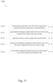
- FIG. 11 depicts an example method of depth map generation, comprising simultaneously capturing 1110 a main-off camera image and an auxiliary-off camera image with an unpowered flash, sparse depth mapping 1112 an object based on the main-off camera image and the auxiliary-off camera image, capturing 1114 a main-on camera image with a powered flash, foreground probability mapping 1116 the object based on the main-off camera image and the main-on camera image and dense depth mapping 1118 the object based on the sparse depth map and the foreground probability map.
- the sparse depth mapping may be based on a corner mapping
- the foreground probability map may be based on a confidence extraction
- the dense depth map may be based on a high confidence corner propagation.
- the main-on camera image may be captured utilizing a set of similar control parameters to the simultaneous capture and the powered flash may be set to a preset flash strength and the powered flash may be one of a visible light flash and an infrared flash.
- the foreground probability mapping may be based on a set of pixel differences between the main-off camera image and the main-on camera image and the main-off camera image and the auxiliary-off camera image may be captured by RGB cameras.
- main-off camera image and the auxiliary-off camera image may be captured by RGBIr cameras.
- a non-transitory computer readable medium comprising instructions, that when read by a processor, cause the processor to perform at least one of simultaneously capturing a main-off camera image and an auxiliary-off camera image with an unpowered flash, sparse depth mapping an object based on the main-off camera image and the auxiliary-off camera image, capturing a main-on camera image with a powered flash, foreground probability mapping the object based on the main-off camera image and the main-on camera image and dense depth mapping the object based on the sparse depth map and the foreground probability map.
- Pronouns in the masculine include the feminine and neuter gender (e.g., her and its) and vice versa. Headings and subheadings, if any, are used for convenience only and do not limit the invention.
- the predicate words “configured to”, “operable to”, and “programmed to” do not imply any particular tangible or intangible modification of a subject, but, rather, are intended to be used interchangeably.
- a processor configured to monitor and control an operation or a component may also mean the processor being programmed to monitor and control the operation or the processor being operable to monitor and control the operation.
- a processor configured to execute code may be construed as a processor programmed to execute code or operable to execute code.
- a phrase such as an “aspect” does not imply that such aspect is essential to the subject technology or that such aspect applies to all configurations of the subject technology.
- a disclosure relating to an aspect may apply to all configurations, or one or more configurations.
- An aspect may provide one or more examples.
- a phrase such as an aspect may refer to one or more aspects and vice versa.
- a phrase such as an “embodiment” does not imply that such embodiment is essential to the subject technology or that such embodiment applies to all configurations of the subject technology.
- a disclosure relating to an embodiment may apply to all embodiments, or one or more embodiments.
- An embodiment may provide one or more examples.
- a phrase such as an “embodiment” may refer to one or more embodiments and vice versa.
- a phrase such as a “configuration” does not imply that such configuration is essential to the subject technology or that such configuration applies to all configurations of the subject technology.
- a disclosure relating to a configuration may apply to all configurations, or one or more configurations.
- a configuration may provide one or more examples.
- a phrase such as a “configuration” may refer to one or more configurations and vice versa.
- example is used herein to mean “serving as an example or illustration.” Any aspect or design described herein as “example” is not necessarily to be construed as preferred or advantageous over other aspects or designs.
- references to “one embodiment,” “an embodiment,” “some embodiments,” “various embodiments”, or the like indicate that a particular element or characteristic is included in at least one embodiment of the invention. Although the phrases may appear in various places, the phrases do not necessarily refer to the same embodiment. In conjunction with the present disclosure, those skilled in the art will be able to design and incorporate any one of the variety of mechanisms suitable for accomplishing the above described functionalities.
Abstract
Description
The two cameras may not be identical co-planar pin-hole cameras. In this case a rectification is applied to the images to simulate captured by two identical co-planar pin-hole cameras. This step includes linear and non-linear transformations. The parameters of these transformations are often calibrated in an offline calibration step, in which a controlled scene will be captured by the system. To recover depth from disparity, the focal length (f) and camera distance (D) are used, which may also be calibrated in the offline calibration step.
E=L·ρ(ωi,ω0)·r −2·cos (1)
Claims (20)
Priority Applications (2)
| Application Number | Priority Date | Filing Date | Title |
|---|---|---|---|
| US17/068,180 US11657529B2 (en) | 2020-10-12 | 2020-10-12 | Multiple camera system with flash for depth map generation |
| CN202110572369.XA CN113298694B (en) | 2020-10-12 | 2021-05-25 | Multi-camera system with flash for depth map generation |
Applications Claiming Priority (1)
| Application Number | Priority Date | Filing Date | Title |
|---|---|---|---|
| US17/068,180 US11657529B2 (en) | 2020-10-12 | 2020-10-12 | Multiple camera system with flash for depth map generation |
Publications (2)
| Publication Number | Publication Date |
|---|---|
| US20220114745A1 US20220114745A1 (en) | 2022-04-14 |
| US11657529B2 true US11657529B2 (en) | 2023-05-23 |
Family
ID=77324766
Family Applications (1)
| Application Number | Title | Priority Date | Filing Date |
|---|---|---|---|
| US17/068,180 Active 2042-01-20 US11657529B2 (en) | 2020-10-12 | 2020-10-12 | Multiple camera system with flash for depth map generation |
Country Status (2)
| Country | Link |
|---|---|
| US (1) | US11657529B2 (en) |
| CN (1) | CN113298694B (en) |
Citations (15)
| Publication number | Priority date | Publication date | Assignee | Title |
|---|---|---|---|---|
| US20040057613A1 (en) * | 2002-09-20 | 2004-03-25 | Nippon Telegraph And Telephone Corp. | Pseudo three dimensional image generating apparatus |
| US20060039690A1 (en) * | 2004-08-16 | 2006-02-23 | Eran Steinberg | Foreground/background segmentation in digital images with differential exposure calculations |
| US20090284627A1 (en) * | 2008-05-16 | 2009-11-19 | Kaibushiki Kaisha Toshiba | Image processing Method |
| US20130182077A1 (en) * | 2012-01-17 | 2013-07-18 | David Holz | Enhanced contrast for object detection and characterization by optical imaging |
| US20130329015A1 (en) * | 2012-06-07 | 2013-12-12 | Kari Pulli | Techniques for generating robust stereo images |
| US20150003725A1 (en) * | 2013-06-28 | 2015-01-01 | Canon Kabushiki Kaisha | Depth constrained superpixel-based depth map refinement |
| US20150235408A1 (en) * | 2014-02-14 | 2015-08-20 | Apple Inc. | Parallax Depth Rendering |
| US9400937B2 (en) * | 2013-11-21 | 2016-07-26 | Nokia Technologies Oy | Method and apparatus for segmentation of foreground objects in images and processing thereof |
| US20160344996A1 (en) * | 2015-05-22 | 2016-11-24 | Intel Corporation | Integrated digital camera platform with nir apodization filter for enhanced depth sensing & image processing |
| US20180249143A1 (en) * | 2017-02-24 | 2018-08-30 | Analog Devices Global | Systems and methods for compression of three dimensional depth sensing |
| US20190037128A1 (en) | 2017-07-28 | 2019-01-31 | Black Sesame International Holding Limited | Fast focus using dual cameras |
| US20190058859A1 (en) * | 2017-08-17 | 2019-02-21 | Microsoft Technology Licensing, Llc | Localized depth map generation |
| US10375378B2 (en) | 2017-12-12 | 2019-08-06 | Black Sesame International Holding Limited | Dual camera system for real-time depth map generation |
| US10742892B1 (en) * | 2019-02-18 | 2020-08-11 | Samsung Electronics Co., Ltd. | Apparatus and method for capturing and blending multiple images for high-quality flash photography using mobile electronic device |
| US20200389642A1 (en) * | 2018-03-31 | 2020-12-10 | Shenzhen Orbbec Co., Ltd. | Target image acquisition system and method |
Family Cites Families (10)
| Publication number | Priority date | Publication date | Assignee | Title |
|---|---|---|---|---|
| US8233077B2 (en) * | 2007-12-27 | 2012-07-31 | Qualcomm Incorporated | Method and apparatus with depth map generation |
| US8605205B2 (en) * | 2011-08-15 | 2013-12-10 | Microsoft Corporation | Display as lighting for photos or video |
| WO2014165244A1 (en) * | 2013-03-13 | 2014-10-09 | Pelican Imaging Corporation | Systems and methods for synthesizing images from image data captured by an array camera using restricted depth of field depth maps in which depth estimation precision varies |
| US10268885B2 (en) * | 2013-04-15 | 2019-04-23 | Microsoft Technology Licensing, Llc | Extracting true color from a color and infrared sensor |
| US20160073094A1 (en) * | 2014-09-05 | 2016-03-10 | Microsoft Corporation | Depth map enhancement |
| US9679387B2 (en) * | 2015-02-12 | 2017-06-13 | Mitsubishi Electric Research Laboratories, Inc. | Depth-weighted group-wise principal component analysis for video foreground/background separation |
| US9973743B2 (en) * | 2015-03-08 | 2018-05-15 | Mediatek Inc. | Electronic device having dynamically controlled flashlight for image capturing and related control method |
| CN105869167A (en) * | 2016-03-30 | 2016-08-17 | 天津大学 | High-resolution depth map acquisition method based on active and passive fusion |
| CN117156114A (en) * | 2019-08-02 | 2023-12-01 | 深圳市灵明光子科技有限公司 | Image acquisition apparatus and method, electronic device, and computer-readable storage medium |
| CN111062981B (en) * | 2019-12-13 | 2023-05-05 | 腾讯科技(深圳)有限公司 | Image processing method, device and storage medium |
-
2020
- 2020-10-12 US US17/068,180 patent/US11657529B2/en active Active
-
2021
- 2021-05-25 CN CN202110572369.XA patent/CN113298694B/en active Active
Patent Citations (15)
| Publication number | Priority date | Publication date | Assignee | Title |
|---|---|---|---|---|
| US20040057613A1 (en) * | 2002-09-20 | 2004-03-25 | Nippon Telegraph And Telephone Corp. | Pseudo three dimensional image generating apparatus |
| US20060039690A1 (en) * | 2004-08-16 | 2006-02-23 | Eran Steinberg | Foreground/background segmentation in digital images with differential exposure calculations |
| US20090284627A1 (en) * | 2008-05-16 | 2009-11-19 | Kaibushiki Kaisha Toshiba | Image processing Method |
| US20130182077A1 (en) * | 2012-01-17 | 2013-07-18 | David Holz | Enhanced contrast for object detection and characterization by optical imaging |
| US20130329015A1 (en) * | 2012-06-07 | 2013-12-12 | Kari Pulli | Techniques for generating robust stereo images |
| US20150003725A1 (en) * | 2013-06-28 | 2015-01-01 | Canon Kabushiki Kaisha | Depth constrained superpixel-based depth map refinement |
| US9400937B2 (en) * | 2013-11-21 | 2016-07-26 | Nokia Technologies Oy | Method and apparatus for segmentation of foreground objects in images and processing thereof |
| US20150235408A1 (en) * | 2014-02-14 | 2015-08-20 | Apple Inc. | Parallax Depth Rendering |
| US20160344996A1 (en) * | 2015-05-22 | 2016-11-24 | Intel Corporation | Integrated digital camera platform with nir apodization filter for enhanced depth sensing & image processing |
| US20180249143A1 (en) * | 2017-02-24 | 2018-08-30 | Analog Devices Global | Systems and methods for compression of three dimensional depth sensing |
| US20190037128A1 (en) | 2017-07-28 | 2019-01-31 | Black Sesame International Holding Limited | Fast focus using dual cameras |
| US20190058859A1 (en) * | 2017-08-17 | 2019-02-21 | Microsoft Technology Licensing, Llc | Localized depth map generation |
| US10375378B2 (en) | 2017-12-12 | 2019-08-06 | Black Sesame International Holding Limited | Dual camera system for real-time depth map generation |
| US20200389642A1 (en) * | 2018-03-31 | 2020-12-10 | Shenzhen Orbbec Co., Ltd. | Target image acquisition system and method |
| US10742892B1 (en) * | 2019-02-18 | 2020-08-11 | Samsung Electronics Co., Ltd. | Apparatus and method for capturing and blending multiple images for high-quality flash photography using mobile electronic device |
Non-Patent Citations (2)
| Title |
|---|
| C. Zhou, A. Troccoli and K. Pulli, "Robust stereo with flash and no-flash image pairs," 2012 IEEE Conference on Computer Vision and Pattern Recognition, Providence, RI, USA, 2012, pp. 342-349, doi: 10.1109/CVPR.2012.6247694. (Year: 2012). * |
| J. Sun, J. Sun, S. B. Kang, Z.-B. Xu, X. Tang and H.-Y. Shum, "Flash Cut: Foreground Extraction with Flash and No-flash Image Pairs," 2007 IEEE Conference on Computer Vision and Pattern Recognition, Minneapolis, MN, USA, 2007, pp. 1-8, doi: 10.1109/CVPR.2007.383080. (Year: 2007). * |
Also Published As
| Publication number | Publication date |
|---|---|
| CN113298694A (en) | 2021-08-24 |
| CN113298694B (en) | 2023-08-08 |
| US20220114745A1 (en) | 2022-04-14 |
Similar Documents
| Publication | Publication Date | Title |
|---|---|---|
| US9392262B2 (en) | System and method for 3D reconstruction using multiple multi-channel cameras | |
| US10068369B2 (en) | Method and apparatus for selectively integrating sensory content | |
| US9948864B2 (en) | Photography illumination compensation method, compensation apparatus, and user equipment | |
| US11330200B2 (en) | Parallax correction using cameras of different modalities | |
| US10916025B2 (en) | Systems and methods for forming models of three-dimensional objects | |
| US10249076B2 (en) | Image processing apparatus, image capturing apparatus, image processing method and storage medium storing image processing program | |
| EP3381015B1 (en) | Systems and methods for forming three-dimensional models of objects | |
| Ngo et al. | Reflectance and shape estimation with a light field camera under natural illumination | |
| WO2019011110A1 (en) | Human face region processing method and apparatus in backlight scene | |
| US20220277512A1 (en) | Generation apparatus, generation method, system, and storage medium | |
| US10839560B1 (en) | Mirror reconstruction | |
| US11657529B2 (en) | Multiple camera system with flash for depth map generation | |
| Rantoson et al. | 3D reconstruction of transparent objects exploiting surface fluorescence caused by UV irradiation | |
| Wang et al. | Separating reflections in human iris images for illumination estimation | |
| Tian et al. | Real-time specularity detection using unnormalized wiener entropy | |
| US11606544B2 (en) | Neural network based auto-white-balancing | |
| US10823950B2 (en) | Camera system with balanced monocular cues for use in digital stereo microscopes | |
| US20220284229A1 (en) | Rgb-nir dual camera face anti-spoofing method | |
| CN111696146B (en) | Face model reconstruction method, face model reconstruction system, image processing system and storage medium | |
| JPH03165737A (en) | Detecting method for line of sight direction | |
| US20230083014A1 (en) | Depth estimation based on data fusion of image sensor and depth sensor frames | |
| WO2023026703A1 (en) | Image analyzing device, method, and program | |
| Chotikakamthorn | Near light source location estimation using illumination of a diffused planar background | |
| Taguchi | Rainbow flash camera: Depth edge extraction using complementary colors | |
| Kobayashi et al. | Interactive Estimation of Light Source Position and Reflectance of Real Objects for Mixed-Reality Application |
Legal Events
| Date | Code | Title | Description |
|---|---|---|---|
| FEPP | Fee payment procedure |
Free format text: ENTITY STATUS SET TO UNDISCOUNTED (ORIGINAL EVENT CODE: BIG.); ENTITY STATUS OF PATENT OWNER: LARGE ENTITY |
|
| FEPP | Fee payment procedure |
Free format text: ENTITY STATUS SET TO SMALL (ORIGINAL EVENT CODE: SMAL); ENTITY STATUS OF PATENT OWNER: LARGE ENTITY |
|
| STPP | Information on status: patent application and granting procedure in general |
Free format text: DOCKETED NEW CASE - READY FOR EXAMINATION |
|
| AS | Assignment |
Owner name: BLACK SESAME INTERNATIONAL HOLDING LIMITED, CALIFORNIA Free format text: ASSIGNMENT OF ASSIGNORS INTEREST;ASSIGNORS:WANG, CHAO;WU, DONGHUI;SIGNING DATES FROM 20201002 TO 20201005;REEL/FRAME:057887/0043 |
|
| FEPP | Fee payment procedure |
Free format text: ENTITY STATUS SET TO UNDISCOUNTED (ORIGINAL EVENT CODE: BIG.); ENTITY STATUS OF PATENT OWNER: LARGE ENTITY |
|
| AS | Assignment |
Owner name: BLACK SESAME TECHNOLOGIES INC., CALIFORNIA Free format text: ASSIGNMENT OF ASSIGNORS INTEREST;ASSIGNOR:BLACK SESAME INTERNATIONAL HOLDING LIMITED;REEL/FRAME:058301/0364 Effective date: 20211121 |
|
| STCF | Information on status: patent grant |
Free format text: PATENTED CASE |