US20170078649A1 - Method and system for unsynchronized structured lighting - Google Patents
Method and system for unsynchronized structured lighting Download PDFInfo
- Publication number
- US20170078649A1 US20170078649A1 US15/124,176 US201515124176A US2017078649A1 US 20170078649 A1 US20170078649 A1 US 20170078649A1 US 201515124176 A US201515124176 A US 201515124176A US 2017078649 A1 US2017078649 A1 US 2017078649A1
- Authority
- US
- United States
- Prior art keywords
- image
- sequence
- image frames
- synchronized
- unsynchronized
- Prior art date
- Legal status (The legal status is an assumption and is not a legal conclusion. Google has not performed a legal analysis and makes no representation as to the accuracy of the status listed.)
- Abandoned
Links
Images
Classifications
-
- G—PHYSICS
- G03—PHOTOGRAPHY; CINEMATOGRAPHY; ANALOGOUS TECHNIQUES USING WAVES OTHER THAN OPTICAL WAVES; ELECTROGRAPHY; HOLOGRAPHY
- G03B—APPARATUS OR ARRANGEMENTS FOR TAKING PHOTOGRAPHS OR FOR PROJECTING OR VIEWING THEM; APPARATUS OR ARRANGEMENTS EMPLOYING ANALOGOUS TECHNIQUES USING WAVES OTHER THAN OPTICAL WAVES; ACCESSORIES THEREFOR
- G03B35/00—Stereoscopic photography
- G03B35/02—Stereoscopic photography by sequential recording
-
- H04N13/0253—
-
- H—ELECTRICITY
- H04—ELECTRIC COMMUNICATION TECHNIQUE
- H04N—PICTORIAL COMMUNICATION, e.g. TELEVISION
- H04N13/00—Stereoscopic video systems; Multi-view video systems; Details thereof
- H04N13/20—Image signal generators
- H04N13/204—Image signal generators using stereoscopic image cameras
- H04N13/254—Image signal generators using stereoscopic image cameras in combination with electromagnetic radiation sources for illuminating objects
-
- G06T7/0057—
-
- G—PHYSICS
- G06—COMPUTING OR CALCULATING; COUNTING
- G06T—IMAGE DATA PROCESSING OR GENERATION, IN GENERAL
- G06T7/00—Image analysis
- G06T7/50—Depth or shape recovery
- G06T7/521—Depth or shape recovery from laser ranging, e.g. using interferometry; from the projection of structured light
-
- H04N13/0051—
-
- H—ELECTRICITY
- H04—ELECTRIC COMMUNICATION TECHNIQUE
- H04N—PICTORIAL COMMUNICATION, e.g. TELEVISION
- H04N13/00—Stereoscopic video systems; Multi-view video systems; Details thereof
- H04N13/10—Processing, recording or transmission of stereoscopic or multi-view image signals
- H04N13/106—Processing image signals
- H04N13/167—Synchronising or controlling image signals
-
- G—PHYSICS
- G06—COMPUTING OR CALCULATING; COUNTING
- G06T—IMAGE DATA PROCESSING OR GENERATION, IN GENERAL
- G06T2207/00—Indexing scheme for image analysis or image enhancement
- G06T2207/10—Image acquisition modality
- G06T2207/10028—Range image; Depth image; 3D point clouds
Definitions
- This patent document relates generally to the field of three-dimensional shape capture of the surface geometry of an object, and more particularly to structured lighting three-dimensional shape capture.
- Three-dimensional scanning and digitization of the surface geometry of objects is commonly used in many industries and services, and their applications are numerous.
- a few examples of such applications are inspection and measurement of shape conformity in industrial production systems, digitization of clay models for industrial design and styling applications, reverse engineering of existing parts with complex geometry for three-dimensional printing, interactive visualization of objects in multimedia applications, three-dimensional documentation of artwork, historic and archaeological artifacts, human body scanning for better orthotics adaptation, biometry or custom-fit clothing, and three-dimensional forensic reconstruction of crime scenes.
- Three dimensional shape capture systems based on structure lighting are more accurate than those based on time-of-flight (TOF) image sensors.
- TOF time-of-flight
- a pattern projector is used to illuminate the scene of interest with a sequence of known two-dimensional patterns, and a camera is used to capture a sequence of images, synchronized with the projected patterns. The camera captures one image for each projected pattern.
- Each sequence of images captured by the camera is decoded by a computer processor into a dense set of projector-camera pixel correspondences, and subsequently into a three-dimensional range image, using the principles of optical triangulation.
- the main limitation of three-dimensional shape capture systems is the required synchronization between projector and camera.
- the sequence of patterns must be projected at a fast rate, the camera must capture image frames exactly at the same frame rate, and the camera has to start capturing the first frame of the sequence exactly when the projector starts to project the first pattern.
- Rolling shutter is a method of image capture in which a still picture or each frame of a video is captured not by taking a snapshot of the entire scene at single instant in time but rather by scanning across the scene rapidly, either vertically or horizontally. In other words, not all parts of the image of the scene are recorded at exactly the same instant. This is in contrast with “global shutter” in which the entire frame is captured at the same instant.
- global shutter Even though most image sensors in consumer devices are rolling shutter sensors, many image sensors used in industrial applications are global shutter sensors.
- a system and method to capture the surface geometry a three-dimensional object in a scene using unsynchronized structured lighting solves the problems of the prior art.
- the method and system includes a pattern projector configured and arranged to project a sequence of image patterns onto the scene at a pattern frame rate, a camera configured and arranged to capture a sequence of unsynchronized image patterns of the scene at an image capture rate; and a processor configured and arranged to synthesize a sequence of synchronized image frames from the unsynchronized image patterns of the scene, each of the synchronized image frames corresponding to one image pattern of the sequence of image patterns. Because the method enables use of an unsynchronized pattern projector and camera significant cost savings can be achieved.
- the method enables use of inexpensive cameras, such as smartphone cameras, webcams, point-and-shoot digital cameras, camcorders as well as industrial cameras. Furthermore, the method and system enable processing the images with a variety of computing hardware, such as computers, digital signal processors, smartphone processors and the like. Consequently, three-dimensional image capture using structured lighting may be used with relatively little capital investment.
- FIG. 1 is an illustration of an exemplary embodiment of the method and system for unsynchronized structured lighting
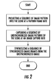
- FIG. 2 shows a flowchart of an exemplary embodiment of the method and system for unsynchronized structured lighting
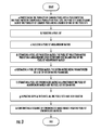
- FIG. 3 shows a flowchart of an exemplary embodiment of the method and system for unsynchronized structured lighting of synthesizing the synchronized sequence of image frames
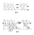
- FIG. 4 is a chart illustrating the timing for a method to synthesize the synchronized sequence of image frames from an unsynchronized sequence of image frames, where a global shutter image sensor is used and where the image frame rate is identical to the pattern frame rate;
- FIG. 5 is a chart illustrating the timing for a method to synthesize the synchronized sequence of image frames from an unsynchronized sequence of image frames, where a rolling shutter image sensor is used and where the image frame rate is identical to the pattern frame rate;
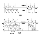
- FIG. 6 is a chart illustrating the timing for a method to synthesize the synchronized sequence of image frames from an unsynchronized sequence of image frames, where a global shutter image sensor is used and where the image frame rate is higher or equal than the pattern frame rate
- FIG. 7 is a chart illustrating the timing for method to synthesize the synchronized sequence of image frames from an unsynchronized sequence of image frames, where a rolling shutter image sensor is used and where the image frame rate is higher or equal than the pattern frame rate;
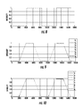
- FIG. 8 shows a chart illustrating a calibration pattern used to correct the time
- FIG. 9 shows a chart illustrating image data normalized according to the method described herein.
- FIG. 10 shows a chart illustrating a model estimating the pattern value for each pixel in a captured image.
- FIGS. 1 and 2 A system and method to capture the surface geometry a three-dimensional object in a scene using unsynchronized structured lighting is shown generally in FIGS. 1 and 2 .
- the method and system includes a pattern projector configured and arranged to project a sequence of image patterns onto the scene at a pattern frame rate, a camera configured and arranged to capture a sequence of unsynchronized image patterns of the scene at an image capture rate; and a processor configured and arranged to synthesize a sequence of synchronized image frames from the unsynchronized image patterns of the scene, each of the synchronized image frames corresponding to one image pattern of the sequence of image patterns.
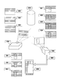
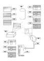
- One object of the present invention is a system to synthesize a synchronized sequence of image frames from an unsynchronized sequence of image frames, illustrated in FIG. 1 ; the unsynchronized image frames captured while a three-dimensional scene was illuminated by a sequence of patterns.
- the system comprises a pattern projector 2020 and a camera 2030 .
- An object 2010 is partially illuminated by the pattern projector 2020 , and partially visible by the camera 2030 .
- the pattern projector projects a sequence of patterns 2021 , 2022 , 2023 at a certain pattern rate.
- the pattern rate is measured in patterns per second.
- the camera 2030 captures a sequence of unsynchronized image frames 2031 , 2032 , 2033 , 2034 , at a certain frame rate.
- the frame rate is larger or equal than the pattern rate.
- the number of unsynchronized image frames captured by the camera is larger or equal than the number of patterns in the sequence of patterns.
- the camera starts capturing the first unsynchronized image frame not earlier than the time when the projector starts projecting the first pattern of the sequence of image patterns.
- the camera ends capturing the last unsynchronized image frame not earlier than the time when the projector ends projecting the last pattern of the sequence of image patterns.
- To capture a frame the camera opens the camera aperture, which it closes after an exposure time.
- the camera determines the pixel values by integrating the incoming light while the aperture is open. Since camera and projector are not synchronized, the projector may switch patterns while the camera has the aperture open.
- the pixels of the captured unsynchronized image frame 2032 will be partially exposed to two consecutive patterns 2021 and 2022 .
- the resulting sequence of unsynchronized image frames are transmitted to a computer processor 2040 , which executes a method to synthesize a synchronized sequence of image frames from the unsynchronized sequence of image frames.
- the number of frames in the synchronized sequence of image frames will be the same as the number of patterns and represent estimates of what the camera would have captured if it were synchronized with the projector.
- the camera 2030 and the computer processor 2040 are components of a single device such a digital camera, smartphone, or computer tablet.
- Another object of the invention is an unsynchronized three-dimensional shape capture system, comprising the system to synthesize a synchronized sequence of image frames from an unsynchronized sequence of image frames described above, and further comprising prior art methods for decoding, three-dimensional triangulation, and optionally geometric processing, executed by the computer processor.
- Another object of the invention is a three-dimensional snapshot camera comprising the unsynchronized three-dimensional shape capture system, where the projector has the means to select the pattern rate from a plurality of supported pattern rates, the camera has the means to select the frame rate from a plurality of supported frame rates, and the camera is capable of capturing the unsynchronized image frames in burst mode at a fast frame rate.
- the projector has a knob to select the pattern rate.
- the pattern rate is set by a pattern rate code sent to the projector through a communications link.
- the system has means to set the pattern rate and the frame rate so that the frame rate is not slower than the pattern rate.
- the user sets the pattern rate and the frame rate.
- the camera has the means to receive a camera trigger signal, and the means to set the number of burst mode frames.
- the camera trigger signal is generated by a camera trigger push-button. When the camera receives the trigger signal it starts capturing the unsynchronized image frames at the set frame rate, and it stops capturing unsynchronized image frames after capturing the set number of burst mode frames.
- the projector continuously projects the sequence of patterns in a cyclic fashion.
- the system has the means of detecting when the first pattern is about to be projected, and the camera trigger signal is delayed until that moment.
- the projector has the means to receive a projector trigger signal.
- the camera generates the projector trigger signal after receiving the camera trigger signal, and the camera has the means to send the projector trigger signal to the projector.
- the camera has a flash trigger output, and it sends the projector trigger signal to the projector through the flash trigger output.
- Another object of this invention is a method to synthesize a synchronized sequence of image frames from an unsynchronized sequence of image frames, generating a number of frames in the synchronized sequence of image frames equal to the number of projected patterns, and representing estimates of what the camera would have captured if it were synchronized with the projector.
- Each of the synchronized image frames corresponds to one of a sequence of image patterns. Further, the synchronized image frames and unsynchronized image frames have the same width and height.
- Each image frame includes a plurality of common pixels.
- a) the plurality of common pixels is partitioned into a pixel partition.
- the pixel partition includes a plurality of pixel sets, each of which is disjoint. Further each of the plurality of common pixels is a member of one of the pixel sets.
- a step b) a pixel set is selected.
- a step c) a pixel set measurement matrix is built.
- a pixel set projection matrix is estimated.
- the pixel set projection matrix projects a measurement space vector onto the column space of the pixel set measurement matrix.
- a pixel set system matrix is estimated.
- the system matrix is parameterized by a set of system matrix parameters.
- a pixel set synchronized matrix as a function of the pixel set measurement matrix and the pixel set system matrix is estimated.
- steps b) to f) are repeated until all the pixels sets have been selected.
- a sequence of synchronized image frames from the pixel set synchronized matrices is constructed.
- the method to synthesize the synchronized sequence of image frames from an unsynchronized sequence of image frames applies to a global shutter image sensor where the image frame rate is identical to the pattern frame rate.
- FIG. 4 illustrates the timing for this embodiment.
- the projector projects N patterns at a fixed frame rate
- a global shutter image sensor capture N images at identical frame rate. Capturing each image takes exactly one unit of time, normalized by the projector frame rate.
- the actual value measured by the image sensor at the (x, y) pixel of the n-th image can be modeled as
- I n ( x, y ) (1 ⁇ t 0 ) P n ( x, y )+ t 0 P n+1 ( x, y )
- P n (x, y) and P n ⁇ 1 (x, y) represent the pattern values to be estimated that contribute to the image pixel (x, y) and P N+1 ⁇ P 1 .
- Projected patterns are known in advance, but since it is not known which projector pixel illuminates each image pixel, they have to be treated as unknown. To estimate the value of t 0 , the following expression is minimized
- the N pattern pixel values P 1 (x, y), . . . , P N (x, y) can be estimated for each pixel (x, y) by minimizing the following expression
- the method to synthesize the synchronized sequence of image frames from an unsynchronized sequence of image frames applies to a rolling shutter image sensor where the image frame rate is identical to the pattern frame rate.
- FIG. 5 illustrates the timing for this embodiment.
- N patterns at fixed framerate a rolling shutter camera captures N images. Capture begins while pattern P 1 is being projected. Projector framerate is 1, pattern P n is projected between time n ⁇ 1 and n.
- a camera frame is read every t f time, camera framerate is assumed equal to projector framerate but in practice may vary a little.
- a camera row requires t r time to be readout from the sensor, thus, a sensor with Y rows needs a time Yt r to read a complete frame, Yt f ⁇ t r .
- Each camera frame is exposed t e time, its readout begins immediately after exposure ends, t e +t r ⁇ t f .
- Camera row y in image n begins being exposed at time t n, y
- I n, y ( n ⁇ t n, y ) k n, y P n +( t n, y +t e ⁇ n ) k n, y P n+1 +C n, y,
- I ⁇ n , y - n ⁇ ⁇ ⁇ ⁇ P n ⁇ 1 t e + ( n - 1 ) ⁇ ⁇ ⁇ ⁇ P n ⁇ t f t e + y ⁇ ⁇ ⁇ ⁇ P n ⁇ t r t e + ⁇ ⁇ ⁇ P n ⁇ t 0 t e + P n + 1
- Image pixel values are given by
- I n ( x, y ) (1 ⁇ t 0 ⁇ yd ) P n ( x, y )+( t 0 +yd ) P n +1( x, y ).
- P n (x, y) and P n+1 (x, y) represent the pattern values contributing to camera pixel (x, y), we define P N+ 1 ⁇ P 1 , P 0 ⁇ P N , I N+1 ⁇ I 1 , and I 0 ⁇ I N , and I will omit pixel (x, y) to simplify the notation. We now minimize the following energy to find the time variables t 0 and d
- [ t 0 d ] ( ⁇ n , x , y ⁇ ⁇ ( P n + 1 - P n ) 2 ⁇ [ 1 y y y 2 ] ) - 1 ⁇ ( ⁇ n , x , y ⁇ ⁇ ( P n + 1 - P n ) ⁇ ( I n - Pn ) ⁇ [ 1 y ] )
- Equation 29 we use Equation 29 to compute t 0 and d when we have some known (or estimated) pattern values.
- the method to synthesize the synchronized sequence of image frames from an unsynchronized sequence of image frames applies to a global shutter image sensor where the image frame rate is higher or equal than the pattern frame rate.
- FIG. 6 illustrates the timing for this embodiment.
- I n 1 ⁇ ⁇ ⁇ t ⁇ ⁇ n ⁇ ( t 0 , ⁇ ⁇ ⁇ t ) T ⁇ p
- ⁇ ( n, m, t 0 , ⁇ t ) max(0, min( m, t n ) ⁇ max( m ⁇ 1 , t n ⁇ 1 ))
- P n (x, y) represents a pattern value contributing to camera pixel (x, y)
- P N+ 1 ⁇ P 1 , P 0 ⁇ P N , I N+1 ⁇ I 1 , and I 0 ⁇ I N we define P N+ 1 ⁇ P 1 , P 0 ⁇ P N , I N+1 ⁇ I 1 , and I 0 ⁇ I N , and I will omit pixel (x, y) to simplify the notation.
- t ( i + 1 ) A t ⁇ ( t ( i ) ) - 1 ⁇ b t ⁇ ( t ( i ) )
- Matrix V A (n, t) and vector V b (n, t) are defined such as
- ⁇ n ⁇ ( t ) V A ⁇ ( n , t ) ⁇ [ t 0 ⁇ ⁇ ⁇ t ] + V b ⁇ ( n , t )
- the method to synthesize the synchronized sequence of image frames from an unsynchronized sequence of image frames applies to a rolling shutter image sensor where the image frame rate is higher or equal than the pattern frame rate.
- FIG. 7 illustrates the timing for this embodiment.
- Projector framerate is 1
- pattern P m is projected between time m ⁇ 1 and m.
- a camera frame is read every t f time.
- a camera row requires t r time to be readout from the sensor, thus, a sensor with Y rows needs a time Yt r to read a complete frame, t f ⁇ Yt r .
- Each camera frame is exposed t e time, its readout begins immediately after exposure ends, t e +t r ⁇ t f .
- Camera row y in image n begins being exposed at time t n, y
- Equation E(h) cannot be minimized in closed form because the values matrix V n, y depends on the unknown values. Using an iterative approach the current value h (i) is used to compute V ny (i) and the next value h (i+1)pl .
- Decoding is done in two steps: 1) the time offset t 0 need to be estimated for this particular sequence; 2) the pattern values are estimated for each camera pixel, as shown in FIG. 10 .
- Value t 0 is estimated using Equation E(h) where the known components of h are fixed, but some pattern values are required to be known, specially we need to know for some pixels whether they are transitioning from ‘black’ to ‘white’ or the opposite. Non-transitioning pixels provided no information in this step. Until now, we have projected a couple of black's and white's at the beginning of the sequence to ensure we can normalized all pixels correctly and to simplify t 0 estimation. We will revisit this point in the future for other pattern sequences.
- the exemplary embodiments of the method and system provides a unique solution to the problem of using structure lighting for three-dimensional image capture where the camera and projector are unsychronized.
Landscapes
- Physics & Mathematics (AREA)
- Engineering & Computer Science (AREA)
- General Physics & Mathematics (AREA)
- Multimedia (AREA)
- Signal Processing (AREA)
- Optics & Photonics (AREA)
- Computer Vision & Pattern Recognition (AREA)
- Theoretical Computer Science (AREA)
- Electromagnetism (AREA)
- Image Processing (AREA)
- Length Measuring Devices By Optical Means (AREA)
Abstract
A system and method to capture the surface geometry a three-dimensional object in a scene using unsynchronized structured lighting is disclosed. The method and system includes a pattern projector configured and arranged to project a sequence of image patterns onto the scene at a pattern frame rate, a camera configured and arranged to capture a sequence of unsynchronized image patterns of the scene at an image capture rate, and a processor configured and arranged to synthesize a sequence of synchronized image frames from the unsynchronized image patterns of the scene. Each of the synchronized image frames corresponds to one image pattern of the sequence of image patterns.
Description
- This application claims priority to earlier filed U.S. Provisional Application Ser. No. 61/949,529, filed Mar. 7, 2014, the contents of which are incorporated herein by reference.
- 1. Field of the Invention
- This patent document relates generally to the field of three-dimensional shape capture of the surface geometry of an object, and more particularly to structured lighting three-dimensional shape capture.
- 2. Background of the Related Art
- Three-dimensional scanning and digitization of the surface geometry of objects is commonly used in many industries and services, and their applications are numerous. A few examples of such applications are inspection and measurement of shape conformity in industrial production systems, digitization of clay models for industrial design and styling applications, reverse engineering of existing parts with complex geometry for three-dimensional printing, interactive visualization of objects in multimedia applications, three-dimensional documentation of artwork, historic and archaeological artifacts, human body scanning for better orthotics adaptation, biometry or custom-fit clothing, and three-dimensional forensic reconstruction of crime scenes.
- One technology for three-dimensional shape capture is based on structured lighting. Three dimensional shape capture systems based on structure lighting are more accurate than those based on time-of-flight (TOF) image sensors. In a standard structured lighting 3D shape capture system a pattern projector is used to illuminate the scene of interest with a sequence of known two-dimensional patterns, and a camera is used to capture a sequence of images, synchronized with the projected patterns. The camera captures one image for each projected pattern. Each sequence of images captured by the camera is decoded by a computer processor into a dense set of projector-camera pixel correspondences, and subsequently into a three-dimensional range image, using the principles of optical triangulation.
- The main limitation of three-dimensional shape capture systems is the required synchronization between projector and camera. To capture a three-dimensional snapshot of a moving scene, the sequence of patterns must be projected at a fast rate, the camera must capture image frames exactly at the same frame rate, and the camera has to start capturing the first frame of the sequence exactly when the projector starts to project the first pattern.
- Therefore, there is a need for three-dimensional shape measurement methods and systems based on structure lighting where the camera and the pattern projector are not synchronized.
- Further complicating matters, image sensors generally use one of two different technologies to capture an image, referred to as “rolling shutter” and “global shutter”. “Rolling shutter” is a method of image capture in which a still picture or each frame of a video is captured not by taking a snapshot of the entire scene at single instant in time but rather by scanning across the scene rapidly, either vertically or horizontally. In other words, not all parts of the image of the scene are recorded at exactly the same instant. This is in contrast with “global shutter” in which the entire frame is captured at the same instant. Even though most image sensors in consumer devices are rolling shutter sensors, many image sensors used in industrial applications are global shutter sensors.
- Therefore, there is a need for three-dimensional shape measurement methods and systems based on structure lighting where the camera and the pattern projector are not synchronized, supporting both global shutter and rolling shutter image sensors.
- A system and method to capture the surface geometry a three-dimensional object in a scene using unsynchronized structured lighting solves the problems of the prior art. The method and system includes a pattern projector configured and arranged to project a sequence of image patterns onto the scene at a pattern frame rate, a camera configured and arranged to capture a sequence of unsynchronized image patterns of the scene at an image capture rate; and a processor configured and arranged to synthesize a sequence of synchronized image frames from the unsynchronized image patterns of the scene, each of the synchronized image frames corresponding to one image pattern of the sequence of image patterns. Because the method enables use of an unsynchronized pattern projector and camera significant cost savings can be achieved. The method enables use of inexpensive cameras, such as smartphone cameras, webcams, point-and-shoot digital cameras, camcorders as well as industrial cameras. Furthermore, the method and system enable processing the images with a variety of computing hardware, such as computers, digital signal processors, smartphone processors and the like. Consequently, three-dimensional image capture using structured lighting may be used with relatively little capital investment.
- These and other features, aspects, and advantages of the method and system will become better understood with reference to the following description, appended claims, and accompanying drawings where:
-
FIG. 1 is an illustration of an exemplary embodiment of the method and system for unsynchronized structured lighting; -
FIG. 2 shows a flowchart of an exemplary embodiment of the method and system for unsynchronized structured lighting; -
FIG. 3 shows a flowchart of an exemplary embodiment of the method and system for unsynchronized structured lighting of synthesizing the synchronized sequence of image frames; -
FIG. 4 is a chart illustrating the timing for a method to synthesize the synchronized sequence of image frames from an unsynchronized sequence of image frames, where a global shutter image sensor is used and where the image frame rate is identical to the pattern frame rate; -
FIG. 5 is a chart illustrating the timing for a method to synthesize the synchronized sequence of image frames from an unsynchronized sequence of image frames, where a rolling shutter image sensor is used and where the image frame rate is identical to the pattern frame rate; -
FIG. 6 is a chart illustrating the timing for a method to synthesize the synchronized sequence of image frames from an unsynchronized sequence of image frames, where a global shutter image sensor is used and where the image frame rate is higher or equal than the pattern frame rate -
FIG. 7 is a chart illustrating the timing for method to synthesize the synchronized sequence of image frames from an unsynchronized sequence of image frames, where a rolling shutter image sensor is used and where the image frame rate is higher or equal than the pattern frame rate; -
FIG. 8 shows a chart illustrating a calibration pattern used to correct the time; -
FIG. 9 shows a chart illustrating image data normalized according to the method described herein; and -
FIG. 10 shows a chart illustrating a model estimating the pattern value for each pixel in a captured image. - A system and method to capture the surface geometry a three-dimensional object in a scene using unsynchronized structured lighting is shown generally in
FIGS. 1 and 2 . The method and system includes a pattern projector configured and arranged to project a sequence of image patterns onto the scene at a pattern frame rate, a camera configured and arranged to capture a sequence of unsynchronized image patterns of the scene at an image capture rate; and a processor configured and arranged to synthesize a sequence of synchronized image frames from the unsynchronized image patterns of the scene, each of the synchronized image frames corresponding to one image pattern of the sequence of image patterns. - One object of the present invention is a system to synthesize a synchronized sequence of image frames from an unsynchronized sequence of image frames, illustrated in
FIG. 1 ; the unsynchronized image frames captured while a three-dimensional scene was illuminated by a sequence of patterns. The system comprises apattern projector 2020 and acamera 2030. Anobject 2010 is partially illuminated by thepattern projector 2020, and partially visible by thecamera 2030. The pattern projector projects a sequence ofpatterns camera 2030 captures a sequence ofunsynchronized image frames unsynchronized image frame 2032 will be partially exposed to twoconsecutive patterns computer processor 2040, which executes a method to synthesize a synchronized sequence of image frames from the unsynchronized sequence of image frames. The number of frames in the synchronized sequence of image frames will be the same as the number of patterns and represent estimates of what the camera would have captured if it were synchronized with the projector. In a preferred embodiment thecamera 2030 and thecomputer processor 2040 are components of a single device such a digital camera, smartphone, or computer tablet. - Another object of the invention is an unsynchronized three-dimensional shape capture system, comprising the system to synthesize a synchronized sequence of image frames from an unsynchronized sequence of image frames described above, and further comprising prior art methods for decoding, three-dimensional triangulation, and optionally geometric processing, executed by the computer processor.
- Another object of the invention is a three-dimensional snapshot camera comprising the unsynchronized three-dimensional shape capture system, where the projector has the means to select the pattern rate from a plurality of supported pattern rates, the camera has the means to select the frame rate from a plurality of supported frame rates, and the camera is capable of capturing the unsynchronized image frames in burst mode at a fast frame rate. In a preferred embodiment the projector has a knob to select the pattern rate. In another preferred embodiment the pattern rate is set by a pattern rate code sent to the projector through a communications link. Furthermore, the system has means to set the pattern rate and the frame rate so that the frame rate is not slower than the pattern rate. In a more preferred embodiment the user sets the pattern rate and the frame rate.
- In a more preferred embodiment of the snapshot camera, the camera has the means to receive a camera trigger signal, and the means to set the number of burst mode frames. In an even more preferred embodiment, the camera trigger signal is generated by a camera trigger push-button. When the camera receives the trigger signal it starts capturing the unsynchronized image frames at the set frame rate, and it stops capturing unsynchronized image frames after capturing the set number of burst mode frames.
- In a first preferred embodiment of the snapshot camera with camera trigger signal, the projector continuously projects the sequence of patterns in a cyclic fashion. In a more preferred embodiment the system has the means of detecting when the first pattern is about to be projected, and the camera trigger signal is delayed until that moment.
- In a second preferred embodiment of the snapshot camera with camera trigger signal, the projector has the means to receive a projector trigger signal. In a more preferred embodiment the camera generates the projector trigger signal after receiving the camera trigger signal, and the camera has the means to send the projector trigger signal to the projector. In an even more preferred embodiment the camera has a flash trigger output, and it sends the projector trigger signal to the projector through the flash trigger output. When the projector receives the trigger signal it starts projecting the sequence of patterns at the set pattern rate, and it stops projecting patterns after it projects the last pattern.
- Another object of this invention is a method to synthesize a synchronized sequence of image frames from an unsynchronized sequence of image frames, generating a number of frames in the synchronized sequence of image frames equal to the number of projected patterns, and representing estimates of what the camera would have captured if it were synchronized with the projector.
- As will be described in greater detail below in the associated proofs, the
- method to synthesize the synchronized sequence of image frames from the unsynchronized sequence of image frames is shown generally in
FIG. 3 . Each of the synchronized image frames corresponds to one of a sequence of image patterns. Further, the synchronized image frames and unsynchronized image frames have the same width and height. Each image frame includes a plurality of common pixels. In a first step a) the plurality of common pixels is partitioned into a pixel partition. The pixel partition includes a plurality of pixel sets, each of which is disjoint. Further each of the plurality of common pixels is a member of one of the pixel sets. In a step b) a pixel set is selected. In a step c) a pixel set measurement matrix is built. In a step d) a pixel set projection matrix is estimated. The pixel set projection matrix projects a measurement space vector onto the column space of the pixel set measurement matrix. In a step e) a pixel set system matrix is estimated. The system matrix is parameterized by a set of system matrix parameters. In a step f) a pixel set synchronized matrix as a function of the pixel set measurement matrix and the pixel set system matrix is estimated. In a step g) steps b) to f) are repeated until all the pixels sets have been selected. In a step h) a sequence of synchronized image frames from the pixel set synchronized matrices is constructed. - In a preferred embodiment, the method to synthesize the synchronized sequence of image frames from an unsynchronized sequence of image frames, applies to a global shutter image sensor where the image frame rate is identical to the pattern frame rate.
FIG. 4 illustrates the timing for this embodiment. In this embodiment, the projector projects N patterns at a fixed frame rate, a global shutter image sensor capture N images at identical frame rate. Capturing each image takes exactly one unit of time, normalized by the projector frame rate. The start time for the first image capture t0 is unknown, but the start time for the n-th image capture is related to the start time for the first image capture tn=t0+n−1. The actual value measured by the image sensor at the (x, y) pixel of the n-th image, can be modeled as -
I n(x, y)=(1−t 0)P n(x, y)+t 0 P n+1(x, y) - where Pn(x, y) and Pn−1(x, y) represent the pattern values to be estimated that contribute to the image pixel (x, y) and PN+1≡P1. Projected patterns are known in advance, but since it is not known which projector pixel illuminates each image pixel, they have to be treated as unknown. To estimate the value of t0, the following expression is minimized
-
- with respect to t0 , where the sum is over a subset of pixels (x, y) for which the corresponding pattern pixel values Pn(x, y) and Pn−1(x, y) are known. Differentiating E(t0) with respect to t0, and equating the result to zero, an expression to estimate t0 is obtained
-
- Once the value of t0 has been estimated, the N pattern pixel values P1(x, y), . . . , PN(x, y) can be estimated for each pixel (x, y) by minimizing the following expression
-
E(P1(x, y), . . . , PN(x, y))= 1 2Σn=1 N((1−t 0)P n(x, y)+t 0 P n+1(x, y)−I n(x, y))2 - which reduces to solving the following system of N linear equations
-
βP n−1(x, y)+αP n(x, y)+βP n+1(x, y)=t0 I n−1(x, y)+(1−t 0)I n(x, y) - for n=1 , . . ., N, where α=t2 0+(1−t0)2 and ⊕=t0(1−−t0).
- In another preferred embodiment, the method to synthesize the synchronized sequence of image frames from an unsynchronized sequence of image frames, applies to a rolling shutter image sensor where the image frame rate is identical to the pattern frame rate.
FIG. 5 illustrates the timing for this embodiment. We project N patterns at fixed framerate, a rolling shutter camera captures N images. Capture begins while pattern P1 is being projected. Projector framerate is 1, pattern Pn is projected between time n−1 and n. A camera frame is read every tf time, camera framerate is assumed equal to projector framerate but in practice may vary a little. A camera row requires tr time to be readout from the sensor, thus, a sensor with Y rows needs a time Ytr to read a complete frame, Ytf≦tr. Each camera frame is exposed te time, its readout begins immediately after exposure ends, te+tr≦tf. - Camera row y in image n begins being exposed at time tn, y
-
t n, y =t 0+(n−1)tf +y t r , y:0 . . . Y−1, - and exposition ends at time tn, y+te
- In this model image n is exposed while pattern Pn and Pn+1 are being projected. Intensity level measured at a pixel in row y is given by
-
I n, y=(n−t n, y)k n, y P n+(t n, y +t e −n)k n, y P n+1 +C n, y, - The constants kn, y and Cn, y are scene dependent.
- Let be min {In, y} a pixel being being exposed while P(t)=0, and max {In, y} a pixel being exposed while P(t)=1, max {In, y}=tekn, y+Cn, y. Now, we define a normalized image Ĩn, y as,
-
- A normalized image is completely defined by the time variables and pattern values. In this section we want to estimate the time variables. Let's rewrite Equation 58 as
-
- being t0 and d unknown. Image pixel values are given by
-
I n(x, y)=(1−t 0 −yd)P n(x, y)+(t 0 +yd)P n+1(x, y). - Same as before, Pn(x, y) and Pn+1 (x, y) represent the pattern values contributing to camera pixel (x, y), we define
P N+1≡P1, P0≡PN, IN+1≡I1, and I0≡IN, and I will omit pixel (x, y) to simplify the notation. We now minimize the following energy to find the time variables t0 and d -
- The partial derivatives are given by
-
- We set the gradient equal to the null vector and reorder as
-
- We use Equation 29 to compute t0 and d when we have some known (or estimated) pattern values.
- With known t0 and d we estimate pattern values minimizing
-
- Analogous as in
Case 1 we obtain that Ap=b with A as inEquation 12 and α, β, and b defined as -
α=(1t 0 −yd)2+(t 0 +yd)2, β=(1−t 0 −yd)(t 0 +yd) -
b=(1−t 0 −yd)(I1 I 2 . . . , I N)T+(t 0 +yd)(I N , I 1 , . . . I N−1)T - Pattern values for each pixel are given by p=A−1 b.
- In another preferred embodiment, the method to synthesize the synchronized sequence of image frames from an unsynchronized sequence of image frames, applies to a global shutter image sensor where the image frame rate is higher or equal than the pattern frame rate.
FIG. 6 illustrates the timing for this embodiment. We now project M patterns at fixed framerate and we capture N images with a global shutter camera, also at a fixed framerate. We require that N≧M. Capture begins while pattern P1 is being projected. We introduce a new variable d which is the camera capture delay from one row to the next. Same as inCase 1, up to two patterns may contribute to each image but here we do not know which ones are because the camera framerate is unknown. The new image equation is -
- Let be Δt≡tn−1−tn the time between image frames, let be p=(P1, . . . , PM)T and Φn(t0, Δt)=(Φ(n, 1, t0, Δt), . . . , Φ(n, M, t0, Δt))T and rewrite Equation 33 as
-
- Each function Φ(n, m, t0, Δt)=∫t
n−1 tn fm(t)dt can be written as -
Φ(n, m, t0, Δt)=max(0, min(m, t n)−max(m−1, t n−1)) - Same as before, Pn(x, y) represents a pattern value contributing to camera pixel (x, y), we define
P N+1≡P1, P0 ≡PN, IN+1≡I1, and I0≡IN, and I will omit pixel (x, y) to simplify the notation. - We now minimize the following energy to find the time variables t0 and Δt
-
- We solve for t0 and Δt by making ∇E(t0, Δt)=0
-
- Because JΦn(t0, Δt) depends on the unknown value t=(t0, Δt)T we solve for them iteratively
-
- Matrix VA(n, t) and vector Vb(n, t) are defined such as
-
- For completeness we include the following definitions:
-
- With known t0 and 66 t we estimate pattern values minimizing
-
- Analogous as in
Case 1 we obtain that Ap=b with -
- Pattern values for each pixel are given by p=A−1b.
- In another preferred embodiment, the method to synthesize the synchronized sequence of image frames from an unsynchronized sequence of image frames, applies to a rolling shutter image sensor where the image frame rate is higher or equal than the pattern frame rate.
FIG. 7 illustrates the timing for this embodiment. Projector framerate is 1, pattern Pm is projected between time m−1 and m. A camera frame is read every tf time. A camera row requires tr time to be readout from the sensor, thus, a sensor with Y rows needs a time Ytr to read a complete frame, tf≧Ytr. Each camera frame is exposed te time, its readout begins immediately after exposure ends, te+tr≦tf. - Camera row y in image n begins being exposed at time tn, y
-
t n, y =t 0+(n−1)t f +y t r , y:0 . . . Y−1 - and exposition ends at time tn, y+te.
- In this model a pixel intensity in image n at row y is given by
-
- The constants kn, y and Cn, y are scene dependent, Pm is either 0 or 1.
- Let be min{In, y} a pixel being exposed while P(t)=0, and max{In, y} a pixel being exposed while P(t)=1,
-
min{In, y}=Cn, y -
max{I n, y }=t e k n, y +C n, y - Now, we define a normalized image Ĩn, yas,
-
- A normalized image is completely defined by the time variables and pattern values. In this section we want to estimate the time variables. Let's rewrite the previous equation as,
-
- We now minimize the following energy to find the unknown h
-
- with the following constraints
-
- or equivalently
-
- Equation E(h) cannot be minimized in closed form because the values matrix Vn, y depends on the unknown values. Using an iterative approach the current value h(i) is used to compute Vny (i) and the next value h(i+1)pl .
- Up to this point we have assumed that the only unknown is h, meaning that pattern values are known for all image pixels. The difficulty lies is knowing which pattern pixel is being observed by each camera pixel. We simplify this issue by making calibration patterns all ‘black or all ‘white’, best seen in
FIG. 8 . For example, a sequence of four patterns ‘{black, black, white, white}’ will produce images with completely black and completely white pixels, as well as pixels in transition from black to white and vice versa. The all black or white pixels are required to produce normalized images, as shown inFIG. 9 , and the pixels in transition constrain the solution of the parameter h in Equation E(h). - Decoding is done in two steps: 1) the time offset t0 need to be estimated for this particular sequence; 2) the pattern values are estimated for each camera pixel, as shown in
FIG. 10 . Value t0 is estimated using Equation E(h) where the known components of h are fixed, but some pattern values are required to be known, specially we need to know for some pixels whether they are transitioning from ‘black’ to ‘white’ or the opposite. Non-transitioning pixels provided no information in this step. Until now, we have projected a couple of black's and white's at the beginning of the sequence to ensure we can normalized all pixels correctly and to simplify t0 estimation. We will revisit this point in the future for other pattern sequences. - Similarly as for the time variables, pattern values are estimated by
- minimizing the following energy
-
- The matrix hTVny T is bi-diagonal for N=M and it is fixed if h is known.
- Therefore, it can be seen that the exemplary embodiments of the method and system provides a unique solution to the problem of using structure lighting for three-dimensional image capture where the camera and projector are unsychronized.
- It would be appreciated by those skilled in the art that various changes and modifications can be made to the illustrated embodiments without departing from the spirit of the present invention. All such modifications and changes are intended to be within the scope of the present invention except as limited by the scope of the appended claims.
- What is claimed is:
Claims (22)
1. A system to capture the surface geometry a three-dimensional object in a scene, comprising:
a pattern projector configured and arranged to project a sequence of image patterns onto the scene at a pattern frame rate;
a camera configured and arranged to capture a sequence of unsynchronized image patterns of the scene at an image capture rate; and
a processor configured and arranged to synthesize a sequence of synchronized image frames from the unsynchronized image patterns of the scene, each of the synchronized image frames corresponding to one image pattern of the sequence of image patterns.
2. The system of claim 1 , wherein the sequence of image patterns comprises binary patterns.
3. The system of claim 1 , wherein the number of image patterns in the sequence of image patterns is less than or equal to the number of unsynchronized image frames in the sequence of unsynchronized image frames.
4. The system of claim 1 , wherein the camera has a rolling shutter operation.
5. The system of claim 1 , wherein the camera has a global shutter operation.
6. The system of claim 1 , wherein the image capture rate of the camera is equal to the pattern frame rate of the projector.
7. The system of claim 1 , wherein the image capture rate of the camera is greater than the pattern frame rate of the projector.
8. A method of capturing the surface geometry of a three-dimensional object in a scene, comprising:
projecting a sequence of image pattern into the scene at a pattern frame rate;
capturing a sequence of unsynchronized image patterns of the scene at an image capture rate; and
synthesizing a sequence of synchronized image frames from the from the unsynchronized image patterns of the scene, each of the synchronized image frames corresponding to one image pattern of the sequence of image patterns.
9. The method of claim 8 , wherein the step of projecting a sequence of image patterns comprises projecting a sequence of binary patterns.
10. The method of claim 8 , wherein the number of image patterns projected in the sequence of image patterns is less than or equal to the number of unsynchronized image frames in the sequence of unsynchronized image frames.
11. The method of claim 8 , further comprising selecting a pattern frame rate.
12. The method of claim 8 , further comprising selecting an image capture rate.
13. The method of claim 8 , wherein the image capture rate is equal to the pattern frame rate.
14. The method of claim 8 , wherein the image capture rate is greater than the pattern frame rate.
15. The method of claim 8 , further comprising decoding the sequence of synchronized image frames.
16. The method of claim 15 , further comprising applying three-dimensional triangulation to the sequence of synchronized image frames.
17. The method of claim 16 , further comprising applying geometric processing to the sequence of synchronized image frames.
18. A method to synthesize a sequence of synchronized image frames synchronized from a sequence of unsynchronized image frames; each of the synchronized image frames corresponding to one of a sequence of image patterns; the synchronized image frames and unsynchronized image frames being image frames of the same width and height; the image frames comprising a plurality of common pixels; the method comprising the steps of:
a) partitioning the plurality of common pixels into a pixel partition; the pixel partition comprising a plurality of pixel sets; the pixel sets being disjoint; each of the plurality of common pixels being a member of one of the pixel sets;
b) selecting a pixel set;
c) building a pixel set measurement matrix;
d) estimating a pixel set projection matrix; the pixel set projection matrix projecting a measurement space vector onto the column space of the pixel set measurement matrix;
e) estimating a pixel set system matrix; the system matrix being parameterized by a set of system matrix parameters;
f) estimating a pixel set synchronized matrix as a function of the pixel set measurement matrix and the pixel set system matrix;
g) repeating steps b) to f) until all the pixels sets have been selected; and
h) constructing a sequence of synchronized image frames from the pixel set synchronized matrices.
19. A method as in claim 18 , where the pixel partition comprises a single pixel set, and the single pixel set contains all the pixels of the image frames.
20. A method as in claim 18 , where the number of pixel sets in the pixel partition is equal to the height of the image frames, and each row of the image frames is a pixel set.
21. A method as in claim 18 , where the pixel set measurement matrix is modeled as the product of the system matrix times the pixel set synchronized matrix, and the step of estimating the pixel set synchronized matrices reduces to the solution of a linear least-squares problem.
22. A method as in claim 18 , where the system matrix is parameterized by an image frame period parameter, an integration time parameter, and a first pattern delay parameter.
Priority Applications (1)
| Application Number | Priority Date | Filing Date | Title |
|---|---|---|---|
| US15/124,176 US20170078649A1 (en) | 2014-03-07 | 2015-03-09 | Method and system for unsynchronized structured lighting |
Applications Claiming Priority (3)
| Application Number | Priority Date | Filing Date | Title |
|---|---|---|---|
| US201461949529P | 2014-03-07 | 2014-03-07 | |
| US15/124,176 US20170078649A1 (en) | 2014-03-07 | 2015-03-09 | Method and system for unsynchronized structured lighting |
| PCT/US2015/019357 WO2015134961A1 (en) | 2014-03-07 | 2015-03-09 | Method and system for unsynchronized structured lighting |
Related Parent Applications (1)
| Application Number | Title | Priority Date | Filing Date |
|---|---|---|---|
| PCT/US2015/019357 A-371-Of-International WO2015134961A1 (en) | 2014-03-07 | 2015-03-09 | Method and system for unsynchronized structured lighting |
Related Child Applications (1)
| Application Number | Title | Priority Date | Filing Date |
|---|---|---|---|
| US16/434,846 Division US20190364264A1 (en) | 2014-03-07 | 2019-06-07 | Method and system for unsynchronized structured lighting |
Publications (1)
| Publication Number | Publication Date |
|---|---|
| US20170078649A1 true US20170078649A1 (en) | 2017-03-16 |
Family
ID=54055938
Family Applications (3)
| Application Number | Title | Priority Date | Filing Date |
|---|---|---|---|
| US15/124,176 Abandoned US20170078649A1 (en) | 2014-03-07 | 2015-03-09 | Method and system for unsynchronized structured lighting |
| US16/434,846 Abandoned US20190364264A1 (en) | 2014-03-07 | 2019-06-07 | Method and system for unsynchronized structured lighting |
| US17/226,920 Active US11425358B2 (en) | 2014-03-07 | 2021-04-09 | Method and system for unsynchronized structured lighting |
Family Applications After (2)
| Application Number | Title | Priority Date | Filing Date |
|---|---|---|---|
| US16/434,846 Abandoned US20190364264A1 (en) | 2014-03-07 | 2019-06-07 | Method and system for unsynchronized structured lighting |
| US17/226,920 Active US11425358B2 (en) | 2014-03-07 | 2021-04-09 | Method and system for unsynchronized structured lighting |
Country Status (2)
| Country | Link |
|---|---|
| US (3) | US20170078649A1 (en) |
| WO (1) | WO2015134961A1 (en) |
Cited By (5)
| Publication number | Priority date | Publication date | Assignee | Title |
|---|---|---|---|---|
| US10154248B2 (en) * | 2015-09-25 | 2018-12-11 | Fujitsu Limited | Encoder apparatus, encoder system, encoding method, and medium for separating frames captured in time series by imaging directions |
| US20200084384A1 (en) * | 2018-09-11 | 2020-03-12 | Cognex Corporation | Methods and apparatus for optimizing image acquisition of objects subject to illumination patterns |
| US20200292306A1 (en) * | 2017-10-17 | 2020-09-17 | Ams Ag | 3d camera system with rolling-shutter image sensor |
| US20210006768A1 (en) * | 2019-07-02 | 2021-01-07 | Coretronic Corporation | Image display device, three-dimensional image processing circuit and synchronization signal correction method thereof |
| US20210409665A1 (en) * | 2020-06-30 | 2021-12-30 | Christie Digital Systems Usa, Inc. | Device, system and method for generating a mapping of projector pixels to camera pixels and/or object positions using alternating patterns |
Families Citing this family (3)
| Publication number | Priority date | Publication date | Assignee | Title |
|---|---|---|---|---|
| CN110446906A (en) | 2017-02-03 | 2019-11-12 | 莫迪特3D公司 | Three-dimensional scanning device and method |
| US10681331B2 (en) | 2017-02-06 | 2020-06-09 | MODit 3D, Inc. | System and method for 3D scanning |
| JP7029654B2 (en) | 2017-07-12 | 2022-03-04 | パナソニックIpマネジメント株式会社 | Projection imaging system, measuring device and projection imaging method |
Citations (2)
| Publication number | Priority date | Publication date | Assignee | Title |
|---|---|---|---|---|
| US20140035480A1 (en) * | 2012-08-02 | 2014-02-06 | Tsvi Blumin | Method for the control of luminance of gas discharge lamps |
| US9256943B2 (en) * | 2013-03-28 | 2016-02-09 | Texas Instruments Incorporated | Projector-camera misalignment correction for structured light systems |
Family Cites Families (11)
| Publication number | Priority date | Publication date | Assignee | Title |
|---|---|---|---|---|
| US6388654B1 (en) * | 1997-10-03 | 2002-05-14 | Tegrity, Inc. | Method and apparatus for processing, displaying and communicating images |
| US8659668B2 (en) * | 2005-10-07 | 2014-02-25 | Rearden, Llc | Apparatus and method for performing motion capture using a random pattern on capture surfaces |
| US7929751B2 (en) * | 2005-11-09 | 2011-04-19 | Gi, Llc | Method and apparatus for absolute-coordinate three-dimensional surface imaging |
| US8016434B2 (en) * | 2008-06-05 | 2011-09-13 | Disney Enterprises, Inc. | Method and system for projecting an animated object and concurrently moving the object's projection area through an animation pattern |
| US8013904B2 (en) * | 2008-12-09 | 2011-09-06 | Seiko Epson Corporation | View projection matrix based high performance low latency display pipeline |
| US9066087B2 (en) * | 2010-11-19 | 2015-06-23 | Apple Inc. | Depth mapping using time-coded illumination |
| CN102760234B (en) * | 2011-04-14 | 2014-08-20 | 财团法人工业技术研究院 | Depth image acquisition device, system and method |
| JP5898484B2 (en) | 2011-12-19 | 2016-04-06 | キヤノン株式会社 | Information processing apparatus, information processing apparatus control method, and program |
| KR102009292B1 (en) * | 2012-05-11 | 2019-08-12 | 한국전자통신연구원 | Apparatus and method for reconstructing three dimensional face based on multiple cameras |
| US10268885B2 (en) | 2013-04-15 | 2019-04-23 | Microsoft Technology Licensing, Llc | Extracting true color from a color and infrared sensor |
| US9569892B2 (en) * | 2013-09-26 | 2017-02-14 | Qualcomm Incorporated | Image capture input and projection output |
-
2015
- 2015-03-09 WO PCT/US2015/019357 patent/WO2015134961A1/en active Application Filing
- 2015-03-09 US US15/124,176 patent/US20170078649A1/en not_active Abandoned
-
2019
- 2019-06-07 US US16/434,846 patent/US20190364264A1/en not_active Abandoned
-
2021
- 2021-04-09 US US17/226,920 patent/US11425358B2/en active Active
Patent Citations (2)
| Publication number | Priority date | Publication date | Assignee | Title |
|---|---|---|---|---|
| US20140035480A1 (en) * | 2012-08-02 | 2014-02-06 | Tsvi Blumin | Method for the control of luminance of gas discharge lamps |
| US9256943B2 (en) * | 2013-03-28 | 2016-02-09 | Texas Instruments Incorporated | Projector-camera misalignment correction for structured light systems |
Cited By (9)
| Publication number | Priority date | Publication date | Assignee | Title |
|---|---|---|---|---|
| US10154248B2 (en) * | 2015-09-25 | 2018-12-11 | Fujitsu Limited | Encoder apparatus, encoder system, encoding method, and medium for separating frames captured in time series by imaging directions |
| US20200292306A1 (en) * | 2017-10-17 | 2020-09-17 | Ams Ag | 3d camera system with rolling-shutter image sensor |
| US20200084384A1 (en) * | 2018-09-11 | 2020-03-12 | Cognex Corporation | Methods and apparatus for optimizing image acquisition of objects subject to illumination patterns |
| US10791277B2 (en) * | 2018-09-11 | 2020-09-29 | Cognex Corporation | Methods and apparatus for optimizing image acquisition of objects subject to illumination patterns |
| US11240435B2 (en) * | 2018-09-11 | 2022-02-01 | Cognex Corporation | Methods and apparatus for optimizing image acquisition of objects subject to illumination patterns |
| US20210006768A1 (en) * | 2019-07-02 | 2021-01-07 | Coretronic Corporation | Image display device, three-dimensional image processing circuit and synchronization signal correction method thereof |
| US20210409665A1 (en) * | 2020-06-30 | 2021-12-30 | Christie Digital Systems Usa, Inc. | Device, system and method for generating a mapping of projector pixels to camera pixels and/or object positions using alternating patterns |
| CN113873207A (en) * | 2020-06-30 | 2021-12-31 | 美国科视数字系统股份有限公司 | Apparatus, system, and method for generating a map using an alternating pattern |
| US11223808B1 (en) * | 2020-06-30 | 2022-01-11 | Christie Digital Systems Usa, Inc. | Device, system and method for generating a mapping of projector pixels to camera pixels and/or object positions using alternating patterns |
Also Published As
| Publication number | Publication date |
|---|---|
| US20190364264A1 (en) | 2019-11-28 |
| US11425358B2 (en) | 2022-08-23 |
| WO2015134961A1 (en) | 2015-09-11 |
| US20210258558A1 (en) | 2021-08-19 |
Similar Documents
| Publication | Publication Date | Title |
|---|---|---|
| US11425358B2 (en) | Method and system for unsynchronized structured lighting | |
| US10161745B2 (en) | Real-time-measurement projection device and three-dimensional-projection measurement device | |
| Vo et al. | Spatiotemporal bundle adjustment for dynamic 3d reconstruction | |
| US9286680B1 (en) | Computational multi-camera adjustment for smooth view switching and zooming | |
| US8350922B2 (en) | Method to compensate the effect of the rolling shutter effect | |
| US9946955B2 (en) | Image registration method | |
| US10359498B2 (en) | Image pickup apparatus having function of generating simulation image,control method therefor, and storage medium | |
| US10872434B2 (en) | Image processing apparatus and method | |
| CN108335322A (en) | Depth estimation method and device, electronic equipment, program and medium | |
| CN106705855A (en) | High-dynamic performance three-dimensional measurement method based on adaptive grating projection | |
| WO2010061956A1 (en) | Stereoscopic image processing device, method, recording medium and stereoscopic imaging apparatus | |
| CN114869528B (en) | Scanning data processing method, device, equipment and medium | |
| JP4831760B2 (en) | 3D information detection method and apparatus | |
| US20180198970A1 (en) | High dynamic range imaging using camera arrays | |
| KR20150145725A (en) | Method and apparatus for dynamic range expansion of ldr video sequence | |
| CN111373222A (en) | Light projection system | |
| CN104427212A (en) | Device and method for removing distortion | |
| US11710247B2 (en) | System for image compositing including training with synthetic data | |
| Zhou et al. | Multi-projector display with continuous self-calibration | |
| US20180091799A1 (en) | Robust disparity estimation in the presence of significant intensity variations for camera arrays | |
| JP2004229093A (en) | Stereoscopic image generating method and stereoscopic image generating apparatus, and stereoscopic image generating program and recording medium | |
| CN100481944C (en) | Method and device for the computer-assisted motion compensation of a digitalized image and computer program products and computer-readable storage media | |
| US20240214697A1 (en) | Image processing device, image processing method, and program | |
| CN110383829B (en) | Image processing apparatus and method | |
| US20230169665A1 (en) | Systems and methods for temporal autocalibration in a camera system |
Legal Events
| Date | Code | Title | Description |
|---|---|---|---|
| AS | Assignment |
Owner name: BROWN UNIVERSITY, RHODE ISLAND Free format text: ASSIGNMENT OF ASSIGNORS INTEREST;ASSIGNORS:TAUBIN, GABRIEL;MORENO, DANIEL;CALAKLI, FATIH;SIGNING DATES FROM 20171024 TO 20171025;REEL/FRAME:047010/0246 |
|
| STCV | Information on status: appeal procedure |
Free format text: NOTICE OF APPEAL FILED |
|
| STCB | Information on status: application discontinuation |
Free format text: ABANDONED -- FAILURE TO RESPOND TO AN OFFICE ACTION |