JP4635392B2 - 3D object surface shape modeling apparatus and program - Google Patents
3D object surface shape modeling apparatus and program Download PDFInfo
- Publication number
- JP4635392B2 JP4635392B2 JP2001242247A JP2001242247A JP4635392B2 JP 4635392 B2 JP4635392 B2 JP 4635392B2 JP 2001242247 A JP2001242247 A JP 2001242247A JP 2001242247 A JP2001242247 A JP 2001242247A JP 4635392 B2 JP4635392 B2 JP 4635392B2
- Authority
- JP
- Japan
- Prior art keywords
- data
- model data
- initial model
- curved surface
- dimensional
- Prior art date
- Legal status (The legal status is an assumption and is not a legal conclusion. Google has not performed a legal analysis and makes no representation as to the accuracy of the status listed.)
- Expired - Lifetime
Links
Images


Classifications
-
- G—PHYSICS
- G06—COMPUTING OR CALCULATING; COUNTING
- G06T—IMAGE DATA PROCESSING OR GENERATION, IN GENERAL
- G06T17/00—Three-dimensional [3D] modelling for computer graphics
- G06T17/30—Polynomial surface description
Landscapes
- Physics & Mathematics (AREA)
- Engineering & Computer Science (AREA)
- General Physics & Mathematics (AREA)
- Computer Graphics (AREA)
- Software Systems (AREA)
- Mathematical Physics (AREA)
- Pure & Applied Mathematics (AREA)
- Mathematical Analysis (AREA)
- Algebra (AREA)
- Geometry (AREA)
- Mathematical Optimization (AREA)
- Theoretical Computer Science (AREA)
- Processing Or Creating Images (AREA)
- Image Processing (AREA)
- Length Measuring Devices By Optical Means (AREA)
- Measurement Of Optical Distance (AREA)
- Image Generation (AREA)
Description
【0001】
【発明の属する技術分野】
本発明は、3次元物体の表面形状モデリング技術に関する。
【0002】
【従来の技術および発明が解決しようとする課題】
<3次元形状入力機により距離画像を直接取得する方法>
レーザやパターン光を物体に照射し、物体表面で反射してくる光をセンサで捉えることにより立体物の3次元形状データ(距離画像データ)を密にサンプリングして入力する3次元形状入力機が、近年CGや工業デザインの分野において使用されることが多くなってきた(投光を行わないタイプのものもあるが精度がよくない)。この理由の一つは、3次元形状入力機の使用により現実の物体の形状を仮想空間に借りてくることができ、簡便に望む3次元モデルを作成することが可能となるからである。
【0003】
しかし、上記のような3次元形状入力機は光の物体表面での乱反射特性を利用しているので、黒髪のような表面反射率の低いもの、金属のような表面が鏡面反射を起こすもの、ガラスのような(半)透明なものなどでは、正しく形状が入力できないか、または、データが欠落してしまう(投光を行わないタイプのものでも同様の現象が発生する)。
【0004】
<シルエットデータを利用する方法>
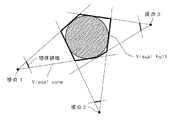
このような場合には、物体の遮蔽輪郭から物体形状を推定するShape from Silhouette法と呼ばれる手法が使用されることが多い。この中でも最もよく使用されている方法の1つはVolume Intersection法と呼ばれ、すべての画像中のシルエット内に収まる3D空間の領域を求める。この領域をVisual Hullと呼び、これを求める最も一般的な方法は以下のようになる。
【0005】
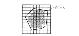
図11に示すように、物体を複数の視点位置から撮影するとともにそのカメラの位置、姿勢などを記録しておく(図では、複数の視点のうち、視点1,2,3を示している)。次に、図12に示すように、仮想3次元空間中の多数のボクセルと呼ばれる立法形状要素を配置する。なお、図11、12は、いずれも便宜的に2次元の模式図として示している。
【0006】
そして、記録しておいたカメラの位置、姿勢などを使用して、ボクセルをすべての画像に投影し、ボクセルのうち、すべての画像において対象物に対応する領域内に投影されたもののみを連結することにより物体の形状を再構成する。
【0007】
Shape from Silhouette法で物体形状を再構成する場合、精度を左右するポイントとなるものの1つは、入力する視点の数である。特に自由曲面物体に対しては、各シルエットに対して、実際の物体表面はごく一部でしか接しないため、生成される3Dモデルは接する部分を除いて元の形状からやや外側に膨らんだ形状となる。図13に、膨らんだ形状として認識される部分(偽の情報)を示している。これを解決するためには、数多くの視点数から入力するほかはない。
【0008】
しかし、数多くの視点から物体の画像を入力するのはユーザへの負担が大きい。回転台やロボットアームなどを用いて自動的に数多くの視点から物体の画像を入力することや、予め多くのカメラを物体の周りに配置しておくことも考えられるが、この方法では、物体の大きさや形状に強い制限が生まれ、また、装置も高価となる。
【0009】
<他の従来の方法>
そこで、曲面モデルを直接シルエットにフィッティングすることにより、シルエットに内接する曲面モデルを生成する方法が、例えばSullivanらによって提案されている。彼らの方法により、スプライン曲面の持つ滑らかである性質を利用してより少ない視点から入力画像を用いて物体の3D形状を生成可能である。
【0010】
ここで、Shape from Silhouette法で作成した3Dデータに曲面モデルをフィッティングせず、シルエットに直接曲面モデルをフィッティングしていることが重要である。シルエットから滑らかな曲面モデルを生成するナイーブな方法としてShape from Silhouette法で作成した3Dデータに曲面モデルをフィッティングすることが考えられるが、入力視点数が少ない場合には大きな歪みを生じてしまう。なぜなら、前述したように、特に少ない視点数のシルエット画像からShape from Silhouette法で作成した3Dデータには多くの偽の情報が含まれるからである。
【0011】
しかし、この方法を使っても、物体表面の中でどの画像にもシルエットとして画像に表れない凹部分は正しく形状が復元できない。つまり、3次元形状入力機により形状データを入力した場合には、上述したように黒髪部分や金属表面などにおいてデータの欠落が生じるといった問題があり、一方、シルエット画像から3Dデータを作成した場合には、凹部分を復元できないといった問題が生じるのである。
【0012】
そこで、特許第2601607号にあるように、3次元形状入力機により形状データを入力すると同時に、シルエット画像から独立に形状を推定し、物体の各部において物体表面の反射率によりどちらか一方を形状情報として選択する方法が提案されている。
【0013】
しかし、この方法は、シルエットから形状を独立に推定するため、3次元形状入力機により入力した部分との境界で、段差などの歪みを発生し易いという欠点がある。また、この方法では、シルエットから形状データを推定するのに、曲面を使用していないため、精度良く形状を再現しようとすると数多くの視点からの入力が必須である。
【0014】
段差を発生させないように、3次元形状入力機で測定した形状とそれとは独立にShape from Silhouette法で推定した形状に、同時に曲面をフィッティングしたり、ブレンドしたりすることも考えられるが、前述したように特に少ない視点数のシルエット画像からShape from Silhouette法で作成した3Dデータには多くの偽の情報が含まれるため、うまくいかない。
【0015】
そこで、本発明は以上のような問題点に鑑み、少ない視点からの撮影データを利用しながら、距離画像データによるモデリング方法とシルエットデータによるモデリング方法の両方の長所を生かした曲面モデルの生成技術を提供することを目的とする。
【0016】
【課題を解決するための手段】
上記課題を解決するため、請求項1の発明は、コンピュータがあつかう仮想空間に3次元物体の曲面モデルデータを生成する装置であって、a)前記仮想空間に前記曲面モデルデータを生成するための初期モデルデータを生成する手段と、b)現実空間に存在する前記3次元物体を計測することにより得られた3次元座標データの集合である測定点群を入力する手段と、c)現実空間に存在する前記3次元物体を撮影することにより得られた2次元の画像データからシルエットデータを生成する手段と、d)前記初期モデルデータの複数の点における局所的な前記初期モデルデータと前記測定点群との近似性を示す第1の適合度を算出する第1の算出手段と、e)前記初期モデルデータの前記複数の点における局所的な前記初期モデルデータと前記シルエットデータとの近似性を示す第2の適合度を算出する第2の算出手段と、f)前記複数の点についての前記第1の適合度と前記第2の適合度との総和を用いて定義される所定の評価量が小さくなるように前記初期モデルデータの前記複数の点を移動して前記初期モデルデータを変形することにより前記3次元物体の曲面モデルデータを生成する生成手段と、を備えることを特徴とする。
【0017】
請求項2の発明は、請求項1に記載の3次元物体の表面形状モデリング装置において、前記生成手段は、f-1)前記初期モデルデータに、テンソル積スプライン曲面をフィッティングすることにより前記曲面モデルデータを生成する手段、を含むことを特徴とする。
【0018】
請求項3の発明は、請求項1または請求項2に記載の3次元物体の表面形状モデリング装置において、前記第1の算出手段は、d-1)前記仮想空間中における前記初期モデルデータと前記測定点群との距離を近似性の尺度として第1の適合度を算出する手段、を含み、前記第2の算出手段は、e-1)前記仮想空間中における前記初期モデルデータと前記シルエットデータとの距離を近似性の尺度として第2の適合度を算出する手段、を含むことを特徴とする。
【0019】
請求項4の発明は、請求項3に記載の3次元物体の表面形状モデリング装置において、前記第2の算出手段は、e-1-1)仮想空間上における撮影視点と当該撮影視点に対応するシルエットの輪郭部とを通る視線を定義し、各視線と前記初期モデルデータとの3次元空間上における距離を近似性の尺度として第2の適合度を算出する手段、を含むことを特徴とする。
【0020】
請求項5の発明は、請求項3に記載の3次元物体の表面形状モデリング装置において、前記第2の算出手段は、e-1-2)前記初期モデルデータを2次元空間に投影することにより得られる2次元投影データと、前記シルエットデータとの2次元空間上の距離を近似性の尺度として第2の適合度を算出する手段、を含むことを特徴とする。
【0021】
請求項6の発明は、請求項3ないし請求項5のいずれかに記載の3次元物体の表面形状モデリング装置において、前記生成手段は、f-2)前記第1の適合度と前記第2の適合度とを所定の比率で加算した加算量を含む統合適合度を前記評価量として算出する手段と、f-3)前記統合適合度が最小となる場合に、前記曲面モデルデータの前記3次元物体への近似性が最も高くなると判断する手段と、を含むことを特徴とする。
【0024】
請求項7の発明は、コンピュータがあつかう仮想空間に3次元物体の曲面モデルデータを生成するプログラムであって、コンピュータを、a)前記仮想空間に前記曲面モデルデータを生成するための初期モデルデータを生成する手段、b)現実空間に存在する前記3次元物体を計測することにより得られた3次元座標データの集合である測定点群を入力する手段、c)現実空間に存在する前記3次元物体を撮影することにより得られた2次元の画像データからシルエットデータを生成する手段、d)前記初期モデルデータの複数の点における局所的な前記初期モデルデータと前記測定点群との近似性を示す第1の適合度を算出する第1の算出手段、e)前記初期モデルデータの前記複数の点における局所的な前記初期モデルデータと前記シルエットデータとの近似性を示す第2の適合度を算出する第2の算出手段、および、f)前記複数の点についての前記第1の適合度と前記第2の適合度との総和を用いて定義される所定の評価量が小さくなるように前記初期モデルデータの前記複数の点を移動して前記初期モデルデータを変形することにより前記3次元物体の曲面モデルデータを生成する生成手段、として機能させることを特徴とする。
【0025】
請求項8の発明は、請求項7に記載のプログラムにおいて、前記生成手段は、f-1)前記初期モデルデータに、テンソル積スプライン曲面をフィッティングすることにより前記曲面モデルデータを生成する手段、を含むことを特徴とする。
【0026】
【発明の実施の形態】
以下、図面を参照しつつ本発明の実施の形態について説明する。
【0027】
{1.システム構成}
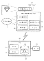
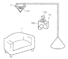
図1、図2を参照しながら、撮影装置10および立体チャート2からなる撮影用システム、および、曲面モデル生成プログラムAPがインストールされたパーソナルコンピュータ20(以下、PC20とする)の構成について説明する。
【0028】
撮影装置10は、3次元物体である被写体1の2次元(2D)カラー画像と距離画像(3次元座標のデータ群)とを同時取得可能な装置である。本実施の形態においては、図2に示すように、デジタルカメラ兼用レンジカメラを撮影装置10として利用する。
【0029】
被写体1が配置される空間内において、被写体1の近傍には、カメラ校正用の立体チャート2が配置されている。立体チャート2は、略角錐状の本体の各側面にチャートパターンCPが施された立体物であり、チャート支持具から吊り下げられている。好ましくは、立体チャート2は被写体1の略上方に吊り下げられる。
【0030】
撮影装置10は、被写体撮影用カメラ10aと可動式カメラ10bとを備えている。さらに、被写体撮影用カメラ10aは、デジタルカメラとしての機能を有する2D撮影部11と、被写体1の距離画像を取得する3D測定部12とを備えている。そして、被写体撮影用カメラ10aの上部に、位置・姿勢センサとして機能する可動式カメラ10bが姿勢変更自在に取り付けられている。
【0031】
可動式カメラ10bは、立体チャート2上のパターンに含まれる複数の単位図形を撮影することにより、立体チャート2と可動式カメラ10bとの相対的な位置姿勢関係を特定し、さらには立体チャート2に対して相対的に固定された絶対座標系における、被写体撮影用カメラ10aの位置および姿勢を検出するために使用される。
【0032】
撮影装置10では、被写体撮影用カメラ10aによって、被写体1の2Dカラー画像および距離画像が入力される際に、同時に、立体チャート2を追尾している可動式カメラ10bによって、立体チャート2の画像が撮影される。そして、解析部15において、被写体撮影カメラ10aの撮影した画像と、可動式カメラ10bの撮影した画像との解析処理が行われ、被写体撮影用カメラ10aの撮影位置データ432および撮影姿勢データ433が算出される(これらのデータは、図5に示すように、後でPC10側に転送される)。なお、可動式カメラ10bに代えて、撮影装置10に加速度センサ付ジャイロセンサを搭載することにより、位置・姿勢データの検出を行うようにしてもよいし、可動式カメラ10bとジャイロセンサとを併用してもよい。
【0033】
そして、算出された撮影位置データ432および撮影姿勢データ433(距離画像データに関して言えば、測定位置データ432および測定姿勢データ433と呼ぶべきであるが)が、被写体1の2Dカラー画像データ41、距離画像データ42と組になってメモリ16に記録される。
【0034】
このとき、光学ユニット制御データ431も同様に一組となってメモリ16に記録される。光学ユニット制御データ431は、被写体撮影用カメラ10aの光学ユニット13から出力される制御信号をデータ化したものであり、被写体撮影用カメラ10aのフォーカス、ズームなどの制御情報である。
【0035】
この光学ユニット制御データ431、撮影位置データ432、および、撮影姿勢データ433を総称して環境データ43と呼ぶことにする。
【0036】
PC20は、CPU21、メモリ22等を備えており、ハードディスク23には、曲面モデル生成プログラムAPがインストールされている。曲面モデル生成プログラムAPの処理内容については後述するが、撮影装置10から入力した2Dカラー画像データ41、距離画像データ42、環境データ43から、被写体1の3次元モデルを生成する処理を実行するものである。
【0037】
撮影装置10からPC20へのデータの転送方法は特に限定されるものではないが、たとえば、IrDA(Infrared Data Association)規格による赤外線通信などを利用することが可能である。
【0038】
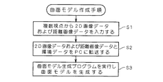
{2.曲面モデル作成手順の概要}
以上の構成からなる3次元モデル生成システムによる曲面モデル作成手順を、図3のフローチャートを用いて説明する。
【0039】
まず、撮影装置10を用いて、複数視点から2Dカラー画像および距離画像の撮影および測定を行う。撮影装置10を被写体1の様々な方向に移動させながら、撮影および測定を行うことにより、これら2Dカラー画像データ41、距離画像データ42と環境データ43とが一組としてメモリ16に順次記録される(ステップS1)。
【0040】
次に、撮影装置10に記録された2Dカラー画像データ41、距離画像データ42および環境データ43をPC20に転送する(ステップS2)。
【0041】
そして、PC20において、曲面モデル生成プログラムAPを起動させ、2Dカラー画像データ41、距離画像データ42、環境データ43を入力データとして処理を実行し、3次元形状モデルである曲面モデルデータ49を生成する(ステップS3)。
【0042】
{3.曲面モデル生成プログラムによる処理内容}
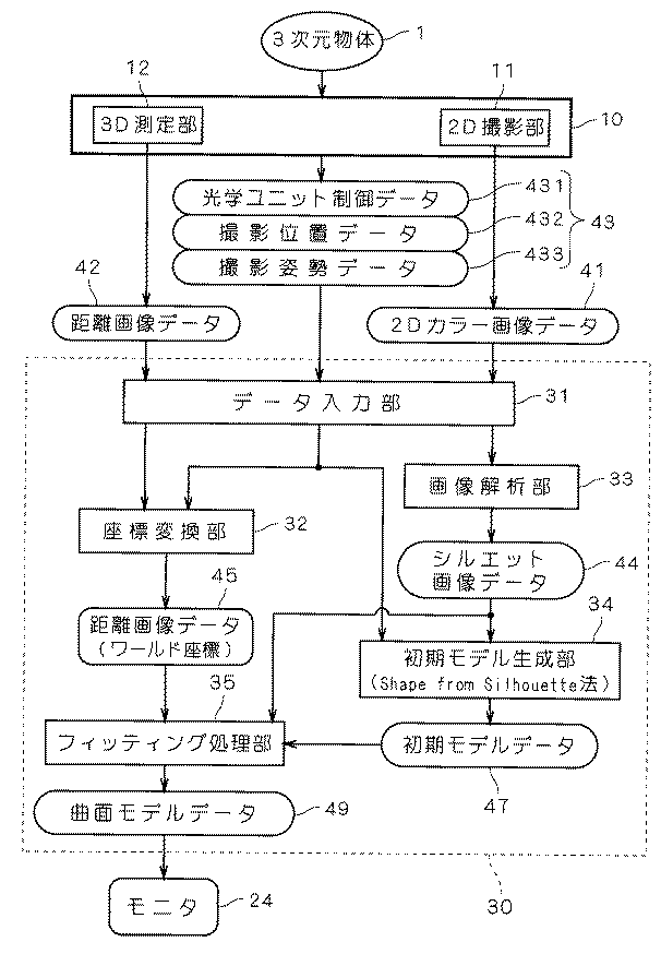
次に、図4のフローチャートおよび図5を参照しながら、曲面モデル生成プログラムAPの処理内容について説明する。図5は、曲面モデル生成部30の機能ブロック構成と各種データの流れを表した図である。曲面モデル生成部30は、曲面モデル生成プログラムAPが、PC20のハードウェア資源を利用することにより実現される機能部であり、図では、さらに、その機能構成を分解して示している。
【0043】
曲面モデル生成部30は、まず、データ入力部31により、2Dカラー画像データ41、距離画像データ42および環境データ43を入力する(ステップS31)。ここで、光学ユニット制御データ431は、事前に作成されている光学ユニット制御データと光学パラメータとの対応テーブルを利用して光学パラメータに変換される。
【0044】
<3−1.距離画像データの変換>
次に、曲面モデル生成部30の座標変換部32により距離画像データ42の座標変換が行われる(ステップS32)。撮影装置10から出力される距離画像データ42は、様々な撮影位置および撮影姿勢で測定された3次元座標のデータ群であり、これらは、被写体撮影用カメラ10aの位置を基準とした相対座標として記録されたものである。
【0045】
そこで、座標変換部31は、環境データ43に含まれる撮影位置データ432、撮影姿勢データ433をもとに、距離画像データ42の相対座標値をワールド座標値に変換するのである。ワールド座標値は、仮想空間上に定義された原点を基準とした座標系であり、様々な撮影位置、撮影姿勢で測定された距離画像データ42が、ワールド座標値に変換されることにより、これらを統一した座標系で扱うことが可能となる。そして、距離画像データ42をワールド座標値において統合することで被写体1の3次元形状データを生成することが可能となるのである。このワールド座標値に変換された距離画像データを、距離画像データ45とする。
【0046】
<3−2.シルエットデータの生成>
次に、曲面モデル生成部30の画像解析部33により2Dカラー画像データ41からシルエット画像データ44の生成処理が行われる(ステップS33)。画像解析部32は、2Dカラー画像データ41を解析し、物体表面と背景との色差をもとに、物体の輪郭を抽出し、シルエットデータ44を生成するのである。シルエット画像データ44は、2値化された画像データであり、たとえば、輪郭の内部を"1"、輪郭の外部を"0"とするようなデータである。
【0047】
このシルエット画像データ44は、ある視点(撮影位置)から見た被写体1のシルエット、つまり、被写体1の2次元空間への投影画像である。そして、様々な視点から撮影された2Dカラー画像データ41が、それぞれ、シルエット画像データ44に変換されることにより、被写体1を各視点からみたシルエットが取得されるのである。
【0048】
<3−3.初期モデルデータの生成>
次に、初期モデル生成部34によりシルエット画像データ44を利用して初期モデルデータ47が生成される(ステップS34)。初期モデルデータ47は、曲面モデル生成部30が最終的に出力する曲面モデルデータ49を生成するための基本となるデータである。つまり、曲面モデル生成部30は、まず、被写体1の大まかな曲面モデルとして初期モデルデータ47を生成し、この初期モデルデータ47を加工することにより、最終的に精度の高い(つまり、現実空間の被写体1により近い)曲面モデルデータ49を生成するのである。
【0049】
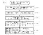
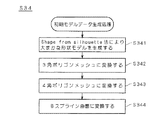
初期モデルデータ47の生成処理について図6のフローチャートを参照しながら説明する。本実施の形態においては、Shape from Silhouette法、とくに、Volume Intersection法により物体の大まかな形状データを生成する(ステップS341)。
【0050】
上述したようにVolume Intersection法は、仮想3次元空間中に多数のボクセルと呼ばれる立方体形状を配置する。そして、各視点(撮影点)と、当該視点からの撮影により取得されたシルエット画像データ44の輪郭(外周部)を結ぶ錐体状の領域内のボクセルを抽出する。そして、各錐体状の領域との共通部分に存在するボクセルを連結することにより被写体1の大まかな形状データが生成される。つまり、Volume Intersection法により求められる被写体1の形状データは、多数の立法格子の集合体として仮想空間上に配置されるものである。
【0051】
なお、各シルエット画像データ44は、異なる視点(撮影位置)から撮影された2Dカラー画像41から抽出されたデータであるため、これら複数のシルエット画像データ44を統合して処理するためには、共通の座標系に変換する必要がある。そこで、初期モデル生成部34は、環境データ43に含まれる光学ユニット制御データ431(光学パラメータ)、撮影位置データ432、撮影姿勢データ433を利用することによって、各視点を共通のワールド座標系に配置したうえで、上記Volume Intersection法を実行するのである。
【0052】
Volume Intersection法により物体の大まかな形状データが求まると、次に、そのデータを3角ポリゴンメッシュデータに変換する(ステップS342)。さらに、後の工程で曲面化を行うために、3角ポリゴンメッシュデータを4角ポリゴンメッシュデータに変換する(ステップS343)。
【0053】
3角ポリゴンメッシュデータを4角ポリゴンメッシュデータに変換する方法は、たとえば、Matthias Eck and Hugues Hoppe, "Automatic reconstruction of B-spline surface of arbitrary topological type",SIGGRAPH'96 Proceedings,1996,Pages325−334にあるように隣接する3角形同士を組み合わせて4角形にすることにより行うことができる。
【0054】
さらに、上記のEckの論文にある方法により、4角形メッシュデータからBスプライン曲面を生成する(ステップS344)。この方法を用いるとBスプライン曲面の制御点は、すべて変換前の4角形メッシュの頂点のアフィン結合で与えられる。
【0055】
Eckらの方法では、4角形メッシュの各ポリゴンに対して自身の頂点と隣接するポリゴンの頂点のアフィン結合により、スプライン曲面パッチを生成する。このとき、隣り合う曲面パッチ同士が滑らかに接続されるようにアフィン結合係数を定めることにより全体として滑らかなスプライン曲面を生成する。
【0056】
ベクトルyがベクトルx1,x2,…xNのアフィン結合で表されているとは、ベクトルyが数1式で表されていることをいう。
【0057】
【数1】
Eckの論文では、j番目のBスプライン曲面の制御点yjは、元の4角形メッシュの頂点x1,x2,…xNを使って数2式のように表されている。
【0059】
【数2】
Bスプライン曲面は、パラメトリック曲面であるテンソル積スプライン曲面の1つであり、Bスプライン曲線と同様の方式で定義される自由曲面である。本実施の形態においては、このように、テンソル積スプライン曲面を利用しているので、一般的なCADやCGのソフトウェアによって、本システムにより生成された曲面モデルを容易に読み込むことが可能である。また、スプライン曲線は、制御点を移動させることにより、曲線の曲率または張力をコントロールすることが可能であるが、Bスプライン曲線は、制御点の移動により局所的な曲線の制御が可能であるという特徴があるので、曲面モデルの修正作業などが行い易い。
【0061】
本実施の形態においては、Bスプライン曲面を使用したが、陰的多項関数、ベジェ曲面パッチ、グレゴリ−パッチ、NURBSなどの他の表現の曲面を使用してもよい。
【0062】
以上の初期モデル生成部34の処理により、被写体1の初期モデルデータ47が生成される。なお、本実施の形態においては、初期モデルデータ47を生成するために、Shape from Silhouette法を利用したが、初期モデルの生成方法は特に限定されるものではない。また、計測データを利用せずに、あらかじめディスク等に蓄積されている所定立体形状サンプルの3Dデータをロードして利用するようにしてもよいし、プリミティブを組み合わせること等により初期モデルを作成するようにしてもよい。
【0063】
以上説明した、距離画像データ42のワールド座標への変換処理(ステップS32)と、初期モデルデータ47の生成処理(ステップS34)の処理順序は特に限定されるものではなく、初期モデルデータ47の生成処理後、距離画像データ42のワールド座標への変換処理を実行するようにしてもよい。
【0064】
<3−4.フィッティング処理>
次に、ステップS34で求めた初期モデルデータ47を用いて最終的な3Dモデルデータ49を生成する処理について説明する。具体的には、初期モデルデータ47と距離画像データ45との間で、仮想空間における両データの近似性を適合度として求め、また、初期モデルデータ47とシルエット画像データ44との間で、仮想空間における両データの近似性を適合度として求め、この2つの適合度の加算量を含む統合適合度をエネルギーとして評価するのである。そして、このエネルギーが最小となるように、初期モデルデータ47を変形することによって3Dモデルデータ49を生成するのである。3Dモデルデータ49の生成は、初期モデルデータ47にBスプライン曲面をフィッティングすることによって行われる(ステップS35)。
【0065】
ここで、上述した距離画像データ45との適合度とシルエット画像データ44との適合度の加算量を含むエネルギーの評価は、次の式を用いる。
【0066】
【数3】
数3式中、J0は、Sullivanの論文にあるようにシルエット上を通る各視線と、その視線から最も近い曲面モデルデータ49(初期状態は初期モデルデータ47)の曲面上の1点との距離の2乗平均である。
【0068】
具体的な算出方法を図7を参照しながら説明する。視点Aと当該視点Aに対応するシルエットBについて、シルエットBの輪郭上の点と視点Aとを結ぶ視線Cを考える。この視線Cを仮想空間上において初期モデルデータ47の領域まで延長させると、初期モデルデータ47の曲面上の各点と各視線Cまでの距離dを算出することができる。そして、各視線Cについて最も近い曲面上の点を選択してその距離dを算出し、全視線について、そのような距離dの2乗平均を算出するのである。
【0069】
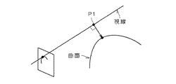
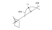
Sullivanらの方法では、シルエットを通る視線が初期モデルデータ47の曲面と交差しないとき(図8で示すようなケース)は視線から最も近い曲面上の点P1を最近点とする。しかし、交差するとき(図9で示すようなケース)は交差する点が常に最近点となってしまうので、これを避けるために、視線からシルエットの外側に向かう法線nの方向に最も遠い曲面上の点を最近点P2として選択する方法がとられているのである。ステップS341においてボクセルの連結として生成された形状モデルは、シルエットを通る視線と交差することはないが、その形状モデルがステップS342〜S344において、3角メッシュ、4角メッシュ、Bスプライン曲面と変形される際に外側に膨らんで変形される場合がある。このような場合に、視線と初期モデルデータ47の曲面とが交差する場合が生じるのである。
【0070】
また、視線に最も近い点の探索は、初期モデルデータ47の曲面上の全ての点について、あらかじめ3次元座標値を求めておき、その中で最も視線に近いものを選択するという方法により、より簡単に算出することが可能である。
【0071】
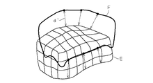
各視線について最も近い曲面上の点を選択する方法として、上記方法は、視線に3次元的に最も近い点を探索する方法をとっているが、画像面上で2次元的に最も近い点を探索する方法でもよい。たとえば、図10に示すように、初期モデルデータ47をシルエット画像データ44と同一の平面上に投影し(この投影されたデータを投影データEとする)、投影された曲面のシルエット上の点の中から、シルエットの輪郭F上の点と最も近い点を選択する方法などが考えられる。ただし、この方法をとる場合、視線と3次元的に最も近い点として選択された点とは同じ点が選択されるわけではない。
【0072】
また、上記方法は、視線と選択された点との3次元的な距離の2乗和を最小とするように評価する方法であるが、画像面上において2次元的な距離(図10における距離d')の2乗和を最小とするように評価する方法でもよい。このような方法をとった場合にも似たような効果が得られるが、たとえば、シルエット画像データ44の中に何枚かのズームアップされた画像が含まれている場合などでは結果に差が生じる。つまり、ズームアップされた画像では、非ズームの場合と比較して、実空間での距離が同じであっても2D画面上ではその距離に対応する画素数が多くなるために、2次元的な距離を評価する方法においては、ズームアップして撮影したシルエット画像に対しては、曲面モデルデータ4との距離が非ズーム画像よりも大きな測度(measure)で評価されることになり、そのシルエットに合致するように重み付けられてフィッティングされるという効果がある。したがって、被写体1の形状の中で特に精密にフィッティングしたい部分がある場合には、他の部分と比較して2D画像の取得の際にその部分の撮影倍率を上げるようにすればよいことになる。
【0073】
また、J1は、距離画像中の各3D点とその3D点から最も近い曲面モデルデータ49(初期状態は初期モデルデータ47)の曲面上の1点との距離の2乗平均である。
【0074】
J2は、やはり、Sullivanの論文にあるように曲面の各部での曲率を評価したものの和であり、一般にthin-plate energyと呼ばれるものである。そして、エネルギーJ2が小さくなるように曲面をフィッティングするということは、曲面を滑らかに繋ぐという効果が得られるものであり、特に、距離画像データ45やシルエット画像データ44が近くにない曲面部分を、その周りと滑らかに繋ぐ役割がある。
【0075】
すなわち、エネルギーJの各成分J0、J1、J2のうち、
(1) J0は、曲面モデルデータ49(初期状態は初期モデルデータ47)とシルエット画像データ44との位置ずれに対応する位置エネルギー、
(2) J1は、曲面モデルデータ49(初期状態は初期モデルデータ47)と距離画像45との位置ずれに対応する位置エネルギー、
(3) J2は、曲面モデルデータ49(初期状態は初期モデルデータ47)の弾性エネルギー、
に相当し、それらのエネルギーの総和を最小とするような変分原理に基づいて、曲面モデルデータ49を決定する。
【0076】
このように、本実施の形態においては、曲面をフィッティングする評価として、シルエット画像データ44との距離を近似性の尺度とした適合度と、距離画像データ45との距離を近似性の尺度とした適合度の両方を評価し、これら適合度の総和が小さくなるように評価しているので、様々な形状、表面特性の被写体1に対しても、より現物に近い形状モデルを被写体1の全周にわたって構成することが可能である。
【0077】
また、上記J0,J1は、それぞれ距離の2乗平均を近似性の尺度として用いているが、近似性の尺度はこれに限定されるものではない。たとえば、距離の絶対値の平均を最小にするような評価をすることも可能である。いずれにしても、ユークリッド空間上における距離を近似性の尺度とし、距離画像とシルエットの双方に対して距離が小さくなるような評価を行うことにより、現実の物体と視覚的に近似した形状モデルを構成することが可能となるのである。
【0078】
数3式を最小とするBスプライン曲面のパラメータは、たとえば、山登り法などを用いて反復計算することができる。
【0079】
ここで、上述したようにBスプライン曲面の制御点はもとの4角形メッシュデータの頂点のアフィン結合で構成されている。つまり、Bスプライン曲面の制御点は元の4角形メッシュの頂点列のアフィン結合として一意に決めることができるので、この曲面の形状を決定する本質的な情報は元の4角形メッシュの頂点列がすべて持っていることとなる。したがって、元の4角形メッシュの頂点列を動かすことのみで、曲面の形状を完全に制御することができるのである。よって、フィッティング処理部35は、元の4角形メッシュの頂点列を動かすことによりデータにフィットする曲面形状を生成するのである。
【0080】
なお、λ0λ1λ2は、ユーザ指定の定数である。ユーザはこれらの定数を操作することにより、距離画像データとの評価を重視する、シルエットデータとの評価を重視する、曲率との評価を重視する、といった重み付けをすることができるのである。被写体1に低反射率の部分が多い場合にはシルエットデータとの評価を重視することが効果的であろうし、凹部が多い場合には、距離画像データとの評価を重視することが効果的である。
【0081】
上記方法により、エネルギーJが最小となるように変形した曲面モデルデータに対して、再び、シルエット上を通る各視線とその視線から最も近い曲面上の点、および、距離画像中の各3D点とその3D点から最も近い曲面上の点を求め直し、さらに、エネルギーJが最小となるように操作を繰り返す。そして、エネルギーJが収束したところで処理を終了し曲面モデルデータ49を出力するのである。
【0082】
すなわち、エネルギーJは、曲面モデルデータ上の各制御点をパラメータとする多変数関数であるため、エネルギーJの全体を最小化するように制御点を動かしたときに、制御点のそれぞれが直接に関係する局所エネルギーのすべてが最小になっているとは限らず、一部の制御点付近の局所エネルギーが変化前よりも高くなったり、制御点と参照画像(シルエット画像や距離画像)との距離を規定する参照画像上の点(図8および図9の例で言えば、点P1やP2:以下「距離定義点」)が、変化前とは別の領域に出現する場合がある。したがって、エネルギーJを一回だけ最小化してもそれが最適解とは限らないため、エネルギーJを一回最小化するごとに距離定義点を再定義し、新たな距離定義点に基づいてエネルギーJの最小化を再度行う、という繰返し演算を、エネルギーJが収束するまで行って(換言すれば、距離定義点の再定義が不要になるまで行って)、最終的な最適解を得ることになる。
【0083】
フィッィング処理部35により曲面モデルデータ49が生成されると、生成された形状モデルがモニタ24上に表示される。さらに、ユーザは、必要に応じて、曲面モデルデータ49に対して修正を加える。また、ユーザは生成された曲面モデルデータ49を他のCGソフトウェア等により自由に修正することが可能である。
【0084】
本実施の形態にかかる曲面モデル生成プログラムは、主に映像製作などの分野に利用される。最近では、WEB上で3Dを表示することにより、WEB上の3Dカタログや3Dマニュアルが提供されているが、これら3Dデータには、物体の全周について、より現物に近い形状モデルが必要とされる。本実施の形態にかかる曲面モデル生成プログラムを利用することで、物体に表面反射率の低い部分や、凹部が存在する場合でも、少ない視点数から物体の全周について形状モデルを構成することが可能であるので、これらの分野への応用が可能である。
【0085】
【発明の効果】
以上説明したように、請求項1記載の発明では、3次元物体を計測することにより得られた3次元座標データの集合である測定点群と、3次元物体を撮影することにより得られた2次元のシルエットデータの両方について近似性を総合的に評価することにより、曲面モデルを生成するので、特に、3次元物体の凹部における形状再現性を最大限保ちながらデータ欠落のない3次元形状モデルを少ない入力視点数で生成可能となる。
【0086】
また、曲面を使用する副次的な効果として、ノイズやキャリブレーションエラーの影響をデータ平滑化により緩和したり、ポリゴンメッシュなどに比べて少ないデータ量で自由曲面を表すなどの効果が得られる。
【0087】
請求項2記載の発明では、曲面の形態として、テンソル積スプライン曲面を採用したので、一般的なCADやCGソフトウェアで容易に読み込むことができ、それらのソフトウェアを利用して修正を行うことや、解析を行うことが可能となる。
【0088】
請求項3記載の発明では、初期モデルデータと測定点群との距離を近似性の尺度として第1の適合度を算出し、初期モデルデータとシルエットデータとの距離を近似性の尺度として第2の適合度を算出するので、測定点群とシルエットデータの双方と視覚的に近似した形状モデルを生成することが可能である。
【0089】
請求項4記載の発明では、シルエット上を通る各視線と初期モデルデータとの距離を近似性の尺度として第2の適合度を算出するので、より再現性の高い3次元モデルを生成可能である。
【0090】
請求項5に記載の発明では、初期モデルデータとシルエットデータとの2次元の画像面上における距離を近似性の尺度として第2の適合度を算出するので、より再現性の高い3次元モデルを生成可能である。
【0091】
請求項6記載の発明では、初期モデルデータと測定点群との距離を近似性の尺度とした第1の適合度と、初期モデルデータとシルエットデータとの距離を近似性の尺度とした第2の適合度との加算量を含む統合適合度を評価し、統合適合度が最も小さくなるように曲面モデルを生成するので、2つの適合度を融合した総合評価が可能となる。
【0093】
請求項7、8記載の発明は、プログラムの発明であり、当該プログラムがコンピュータにおいて実行されることにより、3次元物体の凹部における形状再現性を最大限保ちながらデータ欠落のない3次元形状モデルを少ない入力視点数で生成可能となる。
【図面の簡単な説明】
【図1】3次元形状モデルを生成するシステム全体構成を示す図である。
【図2】撮影システムのイメージ図である。
【図3】曲面モデル作成の全体の手順を示すフローチャートである。
【図4】曲面モデル生成プログラムの機能ブロック構成図と、データの流れを示す図である。
【図5】曲面モデル生成プログラムの処理内容を示すフローチャートである。
【図6】初期モデルデータの生成処理を示すフローチャートである。
【図7】シルエット画像データとの距離を3次元空間上で算出する方法を示す図である。
【図8】視線と曲面とが交差しない場合に定義される距離を示した図である。
【図9】視線と曲面とが交差する場合に定義される距離を示した図である。
【図10】シルエット画像データとの距離を2次元空間上で算出する方法を示す図である。
【図11】 Volume Intersection法による形状データの生成方法を示す図である。
【図12】 visual hull内に存在するボクセルを示す図である。
【図13】各視線と物体との接点、および、Volume Intersection法によって生成された形状データの偽の情報の存在を示す図である。
【符号の説明】
1 被写体(3次元物体)
10 撮影装置
20 PC
31 データ入力部
32 座標変換部
33 画像解析部
34 初期モデル生成部
35 フィッティング処理部
41 2Dカラー画像データ
42 距離画像データ
43 環境データ
44 シルエット画像データ
45 (ワールド座標系)距離画像データ
47 初期モデルデータ
49 曲面モデルデータ
AP 曲面モデル生成プログラム[0001]
BACKGROUND OF THE INVENTION
The present invention relates to a technique for modeling a surface shape of a three-dimensional object.
[0002]
[Background Art and Problems to be Solved by the Invention]
<Method for directly obtaining a distance image with a three-dimensional shape input device>
A three-dimensional shape input machine that irradiates an object with laser or pattern light and captures and reflects light reflected from the object surface with a sensor to sample and input three-dimensional shape data (distance image data) of a three-dimensional object closely. In recent years, it has been increasingly used in the field of CG and industrial design (some types do not perform projection, but the accuracy is not good). One reason for this is that by using a three-dimensional shape input machine, the shape of an actual object can be borrowed in a virtual space, and a desired three-dimensional model can be easily created.
[0003]
However, since the three-dimensional shape input machine as described above uses the irregular reflection characteristics of light on the object surface, it has a low surface reflectivity such as black hair, a metal-like surface causes specular reflection, With a (semi) transparent material such as glass, the shape cannot be input correctly, or data is lost (the same phenomenon occurs even with a type that does not perform projection).
[0004]
<How to use silhouette data>
In such a case, a technique called Shape from Silhouette method is often used to estimate the object shape from the shielding contour of the object. One of the most commonly used methods is called the Volume Intersection method, which finds a 3D space area that fits within the silhouette in all images. This area is called Visual Hull, and the most common way to find it is as follows.
[0005]
As shown in FIG. 11, an object is photographed from a plurality of viewpoint positions, and the positions and orientations of the cameras are recorded (in the figure,
[0006]
Then, using the recorded camera position, posture, etc., the voxels are projected onto all images, and only the voxels that are projected within the area corresponding to the object in all the images are connected. By doing so, the shape of the object is reconstructed.
[0007]
When the object shape is reconstructed by the Shape from Silhouette method, one of the points that influences the accuracy is the number of input viewpoints. In particular, for free-form surfaces, the actual object surface touches only a small part of each silhouette, so the generated 3D model is a shape that swells slightly outward from the original shape except for the touching part. It becomes. FIG. 13 shows a portion (false information) recognized as a swollen shape. In order to solve this, there is no choice but to input from a large number of viewpoints.
[0008]
However, inputting an image of an object from many viewpoints places a heavy burden on the user. It is conceivable to automatically input images of an object from many viewpoints using a turntable or a robot arm, or to arrange many cameras around the object in advance. There are strong limits on size and shape, and the equipment is expensive.
[0009]
<Other conventional methods>
Therefore, for example, Sullivan et al. Have proposed a method of generating a curved surface model inscribed in a silhouette by fitting the curved surface model directly to the silhouette. By their method, it is possible to generate a 3D shape of an object using an input image from a smaller number of viewpoints using the smooth property of a spline curved surface.
[0010]
Here, it is important that the curved surface model is directly fitted to the silhouette without fitting the curved surface model to the 3D data created by the Shape from Silhouette method. As a naive method for generating a smooth curved surface model from a silhouette, it is conceivable to fit a curved surface model to 3D data created by the Shape from Silhouette method. However, when the number of input viewpoints is small, a large distortion occurs. This is because, as described above, 3D data created by the Shape from Silhouette method from a silhouette image having a particularly small number of viewpoints contains a lot of false information.
[0011]
However, even if this method is used, the shape of the concave portion that does not appear in the image as a silhouette in any image on the object surface cannot be restored correctly. In other words, when shape data is input using a three-dimensional shape input device, there is a problem that data is lost in the black hair portion or the metal surface as described above. On the other hand, when 3D data is created from a silhouette image. This causes a problem that the concave portion cannot be restored.
[0012]
Therefore, as disclosed in Japanese Patent No. 2601607, shape data is input from a three-dimensional shape input machine, and at the same time, the shape is estimated independently from the silhouette image. A method of selecting as has been proposed.
[0013]
However, since this method estimates the shape independently from the silhouette, there is a drawback that distortion such as a step is likely to occur at the boundary with the portion input by the three-dimensional shape input machine. In addition, in this method, since a curved surface is not used to estimate shape data from a silhouette, input from many viewpoints is indispensable to reproduce the shape with high accuracy.
[0014]
In order not to generate a step, it is conceivable to simultaneously fit or blend a curved surface to the shape measured by the 3D shape input machine and the shape estimated by the Shape from Silhouette method independently of the shape, as described above. In particular, the 3D data created by the Shape from Silhouette method from silhouette images with a small number of viewpoints contains a lot of fake information, so it does not work.
[0015]
Therefore, in view of the above problems, the present invention provides a curved surface model generation technique that utilizes the advantages of both the modeling method using distance image data and the modeling method using silhouette data while using shooting data from a small number of viewpoints. The purpose is to provide.
[0016]
[Means for Solving the Problems]
In order to solve the above problems, the invention of
[0017]
According to a second aspect of the present invention, in the surface shape modeling apparatus for a three-dimensional object according to the first aspect, the generating means is f-1) fitting the surface model by fitting a tensor product spline surface to the initial model data. Means for generating data.
[0018]
According to a third aspect of the present invention, in the surface shape modeling apparatus for a three-dimensional object according to the first or second aspect, the first calculation means includes: d-1) the initial model data in the virtual space and the Means for calculating a first fitness using the distance to the measurement point group as a measure of approximation, wherein the second calculation means is e-1) the initial model data and the silhouette data in the virtual space. And means for calculating a second fitness using the distance to the measure of approximation.
[0019]
According to a fourth aspect of the present invention, in the surface shape modeling apparatus for a three-dimensional object according to the third aspect, the second calculation means corresponds to the photographing viewpoint in the e-1-1) virtual space and the photographing viewpoint. Means for defining a line of sight passing through the outline of the silhouette, and calculating a second fitness using the distance between each line of sight and the initial model data in a three-dimensional space as a measure of approximation. .
[0020]
According to a fifth aspect of the present invention, in the surface shape modeling apparatus for a three-dimensional object according to the third aspect, the second calculating means is e-1-2) projecting the initial model data onto a two-dimensional space. Means for calculating a second matching degree using a distance between the obtained two-dimensional projection data and the silhouette data in a two-dimensional space as a measure of approximation.
[0021]
According to a sixth aspect of the present invention, in the surface shape modeling apparatus for a three-dimensional object according to any one of the third to fifth aspects, the generation means includes f-2) the first degree of conformity and the second shape. Goodness of fit and Was added at a predetermined ratio Integration suitability including addition amount As the evaluation amount Means for calculating, and f-3) means for determining that the approximation of the curved surface model data to the three-dimensional object is the highest when the integrated fitness is minimum.
[0024]
Claim 7 The present invention is a program for generating curved surface model data of a three-dimensional object in a virtual space handled by a computer, and a) means for generating initial model data for generating the curved surface model data in the virtual space B) means for inputting a measurement point group which is a set of three-dimensional coordinate data obtained by measuring the three-dimensional object existing in the real space; c) photographing the three-dimensional object existing in the real space. Means for generating silhouette data from two-dimensional image data obtained by Local at multiple points of the initial model data A first calculating means for calculating a first matching degree indicating the closeness between the initial model data and the measurement point group; e) Local at the plurality of points of the initial model data; A second calculating means for calculating a second fitness indicating the closeness between the initial model data and the silhouette data; and f) About the plurality of points The first fitness and the second fitness The plurality of points of the initial model data are moved so that a predetermined evaluation amount defined using the sum of The initial model data is deformed to function as generation means for generating curved surface model data of the three-dimensional object.
[0025]
Claim 8 The invention of claim 7 In the program described in (1), the generation means includes f-1) means for generating the curved surface model data by fitting a tensor product spline curved surface to the initial model data.
[0026]
DETAILED DESCRIPTION OF THE INVENTION
Hereinafter, embodiments of the present invention will be described with reference to the drawings.
[0027]
{1. System configuration}
With reference to FIG. 1 and FIG. 2, a configuration of a photographing system including the photographing
[0028]
The
[0029]
In the space where the
[0030]
The photographing
[0031]
The
[0032]
In the photographing
[0033]
Then, the calculated
[0034]
At this time, the optical
[0035]
The optical
[0036]
The
[0037]
A method for transferring data from the photographing
[0038]
{2. Outline of curved surface model creation procedure}
A curved surface model creation procedure by the three-dimensional model generation system configured as described above will be described with reference to the flowchart of FIG.
[0039]
First, using the
[0040]
Next, the 2D
[0041]
Then, the
[0042]
{3. Processing contents by curved surface model generation program}
Next, the processing content of the curved surface model generation program AP will be described with reference to the flowchart of FIG. 4 and FIG. FIG. 5 is a diagram showing the functional block configuration of the curved surface
[0043]
The curved surface
[0044]
<3-1. Conversion of range image data>
Next, the coordinate
[0045]
Therefore, the coordinate
[0046]
<3-2. Generating silhouette data>
Next, generation processing of silhouette image data 44 from 2D
[0047]
The silhouette image data 44 is a silhouette of the subject 1 viewed from a certain viewpoint (shooting position), that is, a projection image of the subject 1 on a two-dimensional space. Then, the 2D
[0048]
<3-3. Generation of initial model data>
Next,
[0049]
The generation process of the
[0050]
As described above, the Volume Intersection method arranges a large number of cubic shapes called voxels in a virtual three-dimensional space. Then, voxels in a cone-shaped region connecting each viewpoint (photographing point) and the contour (outer peripheral part) of the silhouette image data 44 acquired by photographing from the viewpoint are extracted. Then, rough shape data of the subject 1 is generated by connecting voxels existing in common portions with the respective cone-shaped regions. That is, the shape data of the subject 1 obtained by the Volume Intersection method is arranged on the virtual space as an aggregate of a large number of legislative grids.
[0051]
Each silhouette image data 44 is data extracted from the
[0052]
Once the rough shape data of the object is obtained by the Volume Intersection method, the data is then converted into triangular polygon mesh data (step S342). Further, the triangular polygon mesh data is converted into quadrangular polygon mesh data in order to make a curved surface in a later step (step S343).
[0053]
A method for converting triangular polygon mesh data to quadrilateral polygon mesh data is described in, for example, Matthias Eck and Hugues Hoppe, "Automatic reconstruction of B-spline surface of arbitrary topological type", SIGGRAPH '96 Proceedings, 1996, Pages 325-334. It can be performed by combining adjacent triangles to form a square.
[0054]
Further, a B-spline curved surface is generated from the quadrilateral mesh data by the method described in the above Eck paper (step S344). When this method is used, all control points of the B-spline curved surface are given by affine connections of the vertices of the quadrilateral mesh before conversion.
[0055]
In the method of Eck et al., A spline curved surface patch is generated by affine connection of the vertexes of the polygons adjacent to each of the polygons of the quadrilateral mesh. At this time, a smooth spline curved surface as a whole is generated by determining an affine coupling coefficient so that adjacent curved surface patches are smoothly connected.
[0056]
Vector y is vector x 1 , X 2 , ... x N The expression “affine coupling” means that the vector y is expressed by equation (1).
[0057]
[Expression 1]
In Eck's paper, the control point y of the jth B-spline surface j Is the vertex x of the original quadrilateral mesh 1 , X 2 , ... x N It is expressed as in
[0059]
[Expression 2]
The B spline curved surface is one of tensor product spline curved surfaces that are parametric curved surfaces, and is a free curved surface defined in the same manner as the B spline curved surface. In this embodiment, since the tensor product spline curved surface is used as described above, the curved surface model generated by the present system can be easily read by general CAD or CG software. In addition, the spline curve can control the curvature or tension of the curve by moving the control point, but the B spline curve can be controlled locally by moving the control point. Due to the characteristics, it is easy to perform correction work of the curved surface model.
[0061]
In the present embodiment, a B-spline curved surface is used, but curved surfaces of other expressions such as an implicit polynomial function, a Bezier curved surface patch, a Gregory-patch, and a NURBS may be used.
[0062]
The
[0063]
The processing order of the conversion processing of the
[0064]
<3-4. Fitting process>
Next, a process for generating final
[0065]
Here, the following formula is used for the evaluation of energy including the addition amount of the fitness with the
[0066]
[Equation 3]
In
[0068]
A specific calculation method will be described with reference to FIG. Consider a line of sight C connecting a point on the outline of the silhouette B and the viewpoint A with respect to the viewpoint A and the silhouette B corresponding to the viewpoint A. When the line of sight C is extended to the area of the
[0069]
In the method of Sullivan et al., When the line of sight passing through the silhouette does not intersect the curved surface of the initial model data 47 (as shown in FIG. 8), the point P1 on the curved surface closest to the line of sight is set as the closest point. However, when intersecting (in the case shown in FIG. 9), since the intersecting point is always the closest point, in order to avoid this, the curved surface farthest in the direction of the normal n from the line of sight toward the outside of the silhouette The method of selecting the upper point as the nearest point P2 is taken. The shape model generated as a voxel connection in step S341 does not intersect with the line of sight passing through the silhouette, but the shape model is transformed into a triangular mesh, a quadrilateral mesh, or a B-spline curved surface in steps S342 to S344. May swell outward and deform. In such a case, the line of sight and the curved surface of the
[0070]
Further, the search for the point closest to the line of sight is performed by a method in which three-dimensional coordinate values are obtained in advance for all the points on the curved surface of the
[0071]
As a method for selecting a point on the curved surface closest to each line of sight, the above method uses a method of searching for a point that is three-dimensionally closest to the line of sight. A method of searching may be used. For example, as shown in FIG. 10, the
[0072]
Further, the above method is a method for evaluating so that the sum of squares of the three-dimensional distance between the line of sight and the selected point is minimized, but the two-dimensional distance on the image plane (the distance in FIG. 10). A method of evaluating so that the sum of squares of d ′) is minimized may be used. A similar effect can be obtained when this method is used. For example, when the silhouette image data 44 includes several zoomed-up images, there is a difference in the results. Arise. That is, in a zoomed-up image, the number of pixels corresponding to the distance increases on the 2D screen even if the distance in the real space is the same as in the case of non-zoom. In the method of evaluating the distance, for a silhouette image taken by zooming up, the distance from the curved surface model data 4 is evaluated with a measure that is larger than that of the non-zoomed image. There is an effect that fitting is performed by weighting so as to match. Therefore, when there is a part to be particularly precisely fitted in the shape of the subject 1, it is only necessary to increase the photographing magnification of that part when acquiring a 2D image as compared with other parts. .
[0073]
J 1 Is the root mean square of the distance between each 3D point in the distance image and one point on the curved surface of the curved surface model data 49 (
[0074]
J 2 Is the sum of the evaluation of curvature at each part of the curved surface, as in Sullivan's paper, and is generally called thin-plate energy. And energy J 2 Fitting a curved surface so as to reduce the size of the curved surface has the effect of smoothly connecting the curved surface, and in particular, a curved surface portion where the
[0075]
That is, each component J of energy J 0, J 1, J 2 Out of
(1) J 0 Is the potential energy corresponding to the displacement between the curved surface model data 49 (
(2) J 1 Is the potential energy corresponding to the positional deviation between the curved surface model data 49 (initial model is the initial model data 47) and the
(3) J 2 Is the elastic energy of the curved surface model data 49 (the initial state is the initial model data 47),
The curved
[0076]
As described above, in the present embodiment, as an evaluation for fitting a curved surface, the degree of fitness using the distance from the silhouette image data 44 as a measure of closeness and the distance from the
[0077]
In addition, the above J 0 , J 1 Each uses the mean square of distance as a measure of closeness, but the measure of closeness is not limited to this. For example, an evaluation that minimizes the average of absolute values of distances can be performed. In any case, a distance model in Euclidean space is used as a measure of closeness, and a shape model visually approximated to a real object is obtained by evaluating the distance to both the distance image and the silhouette. It becomes possible to configure.
[0078]
The parameter of the B-spline curved surface that minimizes
[0079]
Here, as described above, the control points of the B-spline curved surface are constituted by affine connections of the vertices of the original quadrilateral mesh data. In other words, since the control point of the B-spline curved surface can be uniquely determined as an affine connection of the original quadrilateral mesh vertex row, the essential information for determining the shape of the curved surface is the original quadrilateral mesh vertex row. You will have everything. Therefore, the shape of the curved surface can be completely controlled only by moving the vertex array of the original quadrilateral mesh. Therefore, the fitting processing unit 35 generates a curved surface shape that fits the data by moving the vertex row of the original quadrilateral mesh.
[0080]
Λ 0 λ 1 λ 2 Is a user-specified constant. By manipulating these constants, the user can weight such as emphasizing evaluation with distance image data, emphasizing evaluation with silhouette data, and emphasizing evaluation with curvature. If the
[0081]
With respect to the curved surface model data deformed so that the energy J is minimized by the above method, each line of sight passing through the silhouette, a point on the curved surface closest to the line of sight, and each 3D point in the distance image The point on the curved surface closest to the 3D point is obtained again, and the operation is repeated so that the energy J is minimized. Then, when the energy J has converged, the process is terminated and the curved
[0082]
That is, since energy J is a multivariable function with each control point on the curved surface model data as a parameter, when the control point is moved so as to minimize the entire energy J, each control point is directly Not all of the related local energy is minimized, the local energy near some control points is higher than before the change, or the distance between the control points and the reference image (silhouette image or distance image) In some cases, a point on the reference image defining the point (in the example of FIGS. 8 and 9, points P1 and P2: hereinafter, “distance defining point”) appears in a region different from that before the change. Therefore, even if the energy J is minimized only, it is not always the optimal solution. Therefore, each time the energy J is minimized, the distance definition point is redefined, and the energy J is determined based on the new distance definition point. Is repeated until the energy J converges (in other words, until the redefinition of the distance definition point is unnecessary) to obtain the final optimal solution. .
[0083]
When the curved
[0084]
The curved surface model generation program according to the present embodiment is mainly used in fields such as video production. Recently, 3D catalogs and 3D manuals on WEB have been provided by displaying 3D on WEB, but these 3D data require a shape model that is closer to the actual object for the entire circumference of the object. The By using the curved surface model generation program according to the present embodiment, it is possible to construct a shape model for the entire circumference of the object from a small number of viewpoints even when the surface has a portion with low surface reflectance or a recess. Therefore, application to these fields is possible.
[0085]
【The invention's effect】
As described above, according to the first aspect of the present invention, the measurement point group that is a set of three-dimensional coordinate data obtained by measuring a three-dimensional object and 2 obtained by photographing the three-dimensional object. A curved surface model is generated by comprehensively evaluating the approximateness of both of the three-dimensional silhouette data, and in particular, a three-dimensional shape model without missing data while maintaining the maximum shape reproducibility in the concave portion of the three-dimensional object. Generation is possible with a small number of input viewpoints.
[0086]
Further, as a secondary effect of using a curved surface, effects such as mitigating the influence of noise and calibration error by data smoothing, and representing a free curved surface with a smaller data amount than a polygon mesh or the like can be obtained.
[0087]
In the invention described in
[0088]
According to the third aspect of the present invention, the first fitness is calculated using the distance between the initial model data and the measurement point group as a measure of closeness, and the distance between the initial model data and the silhouette data is used as the second measure of closeness. Therefore, it is possible to generate a shape model that visually approximates both the measurement point group and the silhouette data.
[0089]
In the invention according to claim 4, since the second fitness is calculated using the distance between each line of sight passing on the silhouette and the initial model data as a measure of closeness, it is possible to generate a three-dimensional model with higher reproducibility. .
[0090]
In the invention according to claim 5, since the second fitness is calculated using the distance between the initial model data and the silhouette data on the two-dimensional image plane as a measure of approximation, a more reproducible three-dimensional model is obtained. Can be generated.
[0091]
According to the sixth aspect of the present invention, the first goodness of fit that uses the distance between the initial model data and the measurement point group as a measure of closeness, and the second that uses the distance between the initial model data and silhouette data as a measure of closeness. The integrated fitness including the added amount of the fitness is evaluated, and the curved surface model is generated so that the integrated fitness becomes the smallest. Therefore, it is possible to perform the comprehensive evaluation by fusing the two fitness.
[0093]
Claim 7, 8 The described invention is an invention of a program, and by executing the program on a computer, a three-dimensional shape model without data loss can be obtained with a small number of input viewpoints while maintaining the shape reproducibility in the concave portion of the three-dimensional object. Can be generated.
[Brief description of the drawings]
FIG. 1 is a diagram showing an overall system configuration for generating a three-dimensional shape model.
FIG. 2 is an image diagram of a photographing system.
FIG. 3 is a flowchart showing an overall procedure for creating a curved surface model.
FIG. 4 is a functional block configuration diagram of a curved surface model generation program and a diagram showing a data flow.
FIG. 5 is a flowchart showing the processing contents of a curved surface model generation program.
FIG. 6 is a flowchart showing a process for generating initial model data.
FIG. 7 is a diagram illustrating a method of calculating a distance from silhouette image data in a three-dimensional space.
FIG. 8 is a diagram illustrating a distance defined when a line of sight and a curved surface do not intersect.
FIG. 9 is a diagram illustrating a distance defined when a line of sight and a curved surface intersect each other.
FIG. 10 is a diagram illustrating a method of calculating a distance from silhouette image data in a two-dimensional space.
FIG. 11 is a diagram showing a method for generating shape data by the Volume Intersection method.
FIG. 12 is a diagram showing voxels present in a visual hull.
FIG. 13 is a diagram illustrating the presence of false information in the shape data generated by the contact point between each line of sight and an object and the Volume Intersection method.
[Explanation of symbols]
1 Subject (3D object)
10 Shooting device
20 PC
31 Data input part
32 Coordinate converter
33 Image Analysis Department
34 Initial model generator
35 Fitting processing section
41 2D color image data
42 Distance image data
43 Environmental data
44 Silhouette image data
45 (World coordinate system) Distance image data
47 Initial model data
49 Curved surface model data
AP curved surface model generation program
Claims (8)
a)前記仮想空間に前記曲面モデルデータを生成するための初期モデルデータを生成する手段と、
b)現実空間に存在する前記3次元物体を計測することにより得られた3次元座標データの集合である測定点群を入力する手段と、
c)現実空間に存在する前記3次元物体を撮影することにより得られた2次元の画像データからシルエットデータを生成する手段と、
d)前記初期モデルデータの複数の点における局所的な前記初期モデルデータと前記測定点群との近似性を示す第1の適合度を算出する第1の算出手段と、
e)前記初期モデルデータの前記複数の点における局所的な前記初期モデルデータと前記シルエットデータとの近似性を示す第2の適合度を算出する第2の算出手段と、
f)前記複数の点についての前記第1の適合度と前記第2の適合度との総和を用いて定義される所定の評価量が小さくなるように前記初期モデルデータの前記複数の点を移動して前記初期モデルデータを変形することにより前記3次元物体の曲面モデルデータを生成する生成手段と、
を備えることを特徴とする3次元物体の表面形状モデリング装置。An apparatus for generating curved surface model data of a three-dimensional object in a virtual space handled by a computer,
a) means for generating initial model data for generating the curved surface model data in the virtual space;
b) means for inputting a measurement point group which is a set of three-dimensional coordinate data obtained by measuring the three-dimensional object existing in the real space;
c) means for generating silhouette data from two-dimensional image data obtained by photographing the three-dimensional object existing in the real space;
d) a first calculating means for calculating a first matching degree indicating the closeness between the initial model data locally at a plurality of points of the initial model data and the measurement point group;
e) a second calculating means for calculating a second fitness indicating the closeness between the initial model data locally and the silhouette data at the plurality of points of the initial model data;
f) moving the first fit and the second of said plurality of said initial model data as predetermined evaluation quantity is defined using the sum of the goodness of fit is small point for said plurality of points generating means for generating a surface model data of said three-dimensional body by deforming the initial model data,
A surface shape modeling apparatus for a three-dimensional object.
前記生成手段は、
f-1)前記初期モデルデータに、テンソル積スプライン曲面をフィッティングすることにより前記曲面モデルデータを生成する手段、
を含むことを特徴とする3次元物体の表面形状モデリング装置。The surface shape modeling apparatus for a three-dimensional object according to claim 1,
The generating means includes
f-1) means for generating the curved surface model data by fitting a tensor product spline curved surface to the initial model data;
A surface shape modeling apparatus for a three-dimensional object, comprising:
前記第1の算出手段は、
d-1)前記仮想空間中における前記初期モデルデータと前記測定点群との距離を近似性の尺度として第1の適合度を算出する手段、
を含み、
前記第2の算出手段は、
e-1)前記仮想空間中における前記初期モデルデータと前記シルエットデータとの距離を近似性の尺度として第2の適合度を算出する手段、
を含むことを特徴とする3次元物体の表面形状モデリング装置。The surface shape modeling apparatus for a three-dimensional object according to claim 1 or 2,
The first calculation means includes
d-1) means for calculating a first fitness using a distance between the initial model data and the measurement point group in the virtual space as a measure of approximation;
Including
The second calculation means includes:
e-1) means for calculating a second fitness using the distance between the initial model data and the silhouette data in the virtual space as a measure of approximation;
A surface shape modeling apparatus for a three-dimensional object, comprising:
前記第2の算出手段は、
e-1-1)仮想空間上における撮影視点と当該撮影視点に対応するシルエットの輪郭部とを通る視線を定義し、各視線と前記初期モデルデータとの3次元空間上における距離を近似性の尺度として第2の適合度を算出する手段、
を含むことを特徴とする3次元物体の表面形状モデリング装置。The surface shape modeling apparatus for a three-dimensional object according to claim 3,
The second calculation means includes:
e-1-1) Define the line of sight that passes through the shooting viewpoint in the virtual space and the outline of the silhouette corresponding to the shooting viewpoint, and the distance between each line of sight and the initial model data in the three-dimensional space Means for calculating a second fitness as a scale;
A surface shape modeling apparatus for a three-dimensional object, comprising:
前記第2の算出手段は、
e-1-2)前記初期モデルデータを2次元空間に投影することにより得られる2次元投影データと、前記シルエットデータとの2次元空間上の距離を近似性の尺度として第2の適合度を算出する手段、
を含むことを特徴とする3次元物体の表面形状モデリング装置。The surface shape modeling apparatus for a three-dimensional object according to claim 3,
The second calculation means includes:
e-1-2) The second goodness of fit is obtained by using the distance in the two-dimensional space between the two-dimensional projection data obtained by projecting the initial model data on the two-dimensional space and the silhouette data as a measure of approximation. Means for calculating,
A surface shape modeling apparatus for a three-dimensional object, comprising:
前記生成手段は、
f-2)前記第1の適合度と前記第2の適合度とを所定の比率で加算した加算量を含む統合適合度を前記評価量として算出する手段と、
f-3)前記統合適合度が最小となる場合に、前記曲面モデルデータの前記3次元物体への近似性が最も高くなると判断する手段と、
を含むことを特徴とする3次元物体の表面形状モデリング装置。The surface shape modeling apparatus for a three-dimensional object according to any one of claims 3 to 5,
The generating means includes
f-2) means for calculating, as the evaluation quantity , an integrated fitness including an addition amount obtained by adding the first fitness and the second fitness at a predetermined ratio ;
f-3) means for determining that the approximation of the curved surface model data to the three-dimensional object is highest when the integrated fitness is minimum;
A surface shape modeling apparatus for a three-dimensional object, comprising:
コンピュータを、
a)前記仮想空間に前記曲面モデルデータを生成するための初期モデルデータを生成する手段、
b)現実空間に存在する前記3次元物体を計測することにより得られた3次元座標データの集合である測定点群を入力する手段、
c)現実空間に存在する前記3次元物体を撮影することにより得られた2次元の画像データからシルエットデータを生成する手段、
d)前記初期モデルデータの複数の点における局所的な前記初期モデルデータと前記測定点群との近似性を示す第1の適合度を算出する第1の算出手段、
e)前記初期モデルデータの前記複数の点における局所的な前記初期モデルデータと前記シルエットデータとの近似性を示す第2の適合度を算出する第2の算出手段、および、
f)前記複数の点についての前記第1の適合度と前記第2の適合度との総和を用いて定義される所定の評価量が小さくなるように前記初期モデルデータの前記複数の点を移動して前記初期モデルデータを変形することにより前記3次元物体の曲面モデルデータを生成する生成手段、
として機能させることを特徴とするプログラム。 A program for generating curved surface model data of a three-dimensional object in a virtual space handled by a computer,
Computer
a) means for generating initial model data for generating the curved surface model data in the virtual space ;
b) means for inputting a measurement point group which is a set of three-dimensional coordinate data obtained by measuring the three-dimensional object existing in the real space ;
c) means for generating silhouette data from two-dimensional image data obtained by photographing the three-dimensional object existing in the real space ;
d) a first calculating means for calculating a first fitness indicating locality of the initial model data locally at a plurality of points of the initial model data and the measurement point group ;
e) a second calculating means for calculating a second fitness indicating the closeness between the initial model data locally and the silhouette data at the plurality of points of the initial model data ; and
f) moving the first fit and the second of said plurality of said initial model data as predetermined evaluation quantity is defined using the sum of the goodness of fit is small point for said plurality of points generating means for generating a surface model data of said three-dimensional body by deforming the initial model data,
A program characterized by functioning as
前記生成手段は、
f-1)前記初期モデルデータに、テンソル積スプライン曲面をフィッティングすることにより前記曲面モデルデータを生成する手段、
を含むことを特徴とするプログラム。The program according to claim 7,
The generating means includes
f-1) means for generating the curved surface model data by fitting a tensor product spline curved surface to the initial model data;
The program characterized by including.
Priority Applications (2)
| Application Number | Priority Date | Filing Date | Title |
|---|---|---|---|
| JP2001242247A JP4635392B2 (en) | 2001-08-09 | 2001-08-09 | 3D object surface shape modeling apparatus and program |
| US10/214,363 US6937235B2 (en) | 2001-08-09 | 2002-08-08 | Three-dimensional object surface shape modeling apparatus, method and program |
Applications Claiming Priority (1)
| Application Number | Priority Date | Filing Date | Title |
|---|---|---|---|
| JP2001242247A JP4635392B2 (en) | 2001-08-09 | 2001-08-09 | 3D object surface shape modeling apparatus and program |
Publications (2)
| Publication Number | Publication Date |
|---|---|
| JP2003058911A JP2003058911A (en) | 2003-02-28 |
| JP4635392B2 true JP4635392B2 (en) | 2011-02-23 |
Family
ID=19072555
Family Applications (1)
| Application Number | Title | Priority Date | Filing Date |
|---|---|---|---|
| JP2001242247A Expired - Lifetime JP4635392B2 (en) | 2001-08-09 | 2001-08-09 | 3D object surface shape modeling apparatus and program |
Country Status (2)
| Country | Link |
|---|---|
| US (1) | US6937235B2 (en) |
| JP (1) | JP4635392B2 (en) |
Families Citing this family (39)
| Publication number | Priority date | Publication date | Assignee | Title |
|---|---|---|---|---|
| US7423666B2 (en) * | 2001-05-25 | 2008-09-09 | Minolta Co., Ltd. | Image pickup system employing a three-dimensional reference object |
| US6950099B2 (en) * | 2002-07-01 | 2005-09-27 | Alias Systems Corp. | Approximation of Catmull-Clark subdivision surfaces by Bezier patches |
| JP2004199496A (en) * | 2002-12-19 | 2004-07-15 | Sony Corp | Information processing apparatus and method, and program |
| GB0305315D0 (en) * | 2003-03-07 | 2003-04-09 | Weber Martin | Image processing system |
| JP2006523891A (en) * | 2003-03-26 | 2006-10-19 | ブリガム・ヤング・ユニバーシティ | System and method for defining T-splines and T-NURCC surfaces using local refinement |
| EP1653191A4 (en) * | 2003-07-11 | 2010-09-08 | Olympus Corp | Information presentation device and information presentation system using the same |
| JP4766839B2 (en) * | 2003-08-28 | 2011-09-07 | 富士通株式会社 | Measuring method, measuring system and program |
| US7583272B2 (en) | 2004-11-29 | 2009-09-01 | Purdue Research Foundation | Methods for retrieving shapes and drawings |
| KR100809521B1 (en) * | 2005-12-08 | 2008-03-04 | 한국전자통신연구원 | Method and apparatus of surface reconstruction using corresponding curves in multiple images |
| JP5285487B2 (en) * | 2009-03-31 | 2013-09-11 | 日本放送協会 | Image recording system and image recording method |
| KR101271460B1 (en) * | 2009-12-02 | 2013-06-05 | 한국전자통신연구원 | Video restoration apparatus and its method |
| TWI393071B (en) * | 2010-02-12 | 2013-04-11 | 國立清華大學 | Image processing method and system capable of retaining image features |
| GB2489495B (en) * | 2011-03-31 | 2013-03-06 | Rolls Royce Plc | Checking positional accuracy of features |
| US8803885B1 (en) | 2011-09-07 | 2014-08-12 | Infragistics, Inc. | Method for evaluating spline parameters for smooth curve sampling |
| US9530060B2 (en) | 2012-01-17 | 2016-12-27 | Avigilon Fortress Corporation | System and method for building automation using video content analysis with depth sensing |
| US8754887B2 (en) * | 2012-07-20 | 2014-06-17 | Google Inc. | Determining three-dimensional (3D) object data models based on object movement |
| JP2014074615A (en) * | 2012-10-03 | 2014-04-24 | Stanley Electric Co Ltd | Three-dimensional information generation device and three-dimensional information generation method |
| US20140307055A1 (en) | 2013-04-15 | 2014-10-16 | Microsoft Corporation | Intensity-modulated light pattern for active stereo |
| WO2015021381A1 (en) * | 2013-08-08 | 2015-02-12 | University Of Florida Research Foundation, Incorporated | Real-time reconstruction of the human body and automated avatar synthesis |
| US9438891B2 (en) * | 2014-03-13 | 2016-09-06 | Seiko Epson Corporation | Holocam systems and methods |
| CN104050720B (en) * | 2014-06-24 | 2017-02-15 | 中国科学院深圳先进技术研究院 | Point cloud curve plane reconstruction method and system |
| WO2017031718A1 (en) * | 2015-08-26 | 2017-03-02 | 中国科学院深圳先进技术研究院 | Modeling method of deformation motions of elastic object |
| EP3467765B1 (en) * | 2016-05-23 | 2024-10-23 | Sony Group Corporation | Electronic device, control method for electronic device, and program |
| JP6838912B2 (en) * | 2016-09-29 | 2021-03-03 | キヤノン株式会社 | Image processing equipment, image processing methods and programs |
| JP7105223B2 (en) * | 2017-03-23 | 2022-07-22 | 株式会社Fuji | robot system |
| US10504251B1 (en) * | 2017-12-13 | 2019-12-10 | A9.Com, Inc. | Determining a visual hull of an object |
| CN109671153B (en) * | 2018-12-05 | 2022-12-30 | 安徽慧软科技有限公司 | Three-dimensional reconstruction method for contour line of complex organ |
| CN109580649B (en) * | 2018-12-18 | 2020-11-27 | 清华大学 | A method and system for identification and projection correction of surface cracks in engineering structures |
| KR102221292B1 (en) * | 2019-02-21 | 2021-02-26 | 순천향대학교 산학협력단 | 3d surface printing method |
| JP7192595B2 (en) | 2019-03-18 | 2022-12-20 | 日本電信電話株式会社 | Structure detection device, structure detection method, and structure detection processing program |
| US20220284667A1 (en) * | 2019-08-23 | 2022-09-08 | Art & Space It Inc. | Image processing method and image processing device for generating 3d content by means of 2d images |
| EP3866107A1 (en) * | 2020-02-14 | 2021-08-18 | Koninklijke Philips N.V. | Model-based image segmentation |
| US12511824B2 (en) * | 2020-09-25 | 2025-12-30 | Medit Corp. | Three-dimensional modeling method and apparatus using same |
| CN112364402B (en) * | 2020-10-27 | 2022-04-08 | 成都飞机工业(集团)有限责任公司 | Method for quickly generating curved surface mesh for laying simulation step |
| CN114383531B (en) * | 2021-12-24 | 2023-02-17 | 上海交通大学 | Method and system for detecting three-dimensional profile of spherical optical lens |
| JP2023104131A (en) | 2022-01-17 | 2023-07-28 | キヤノン株式会社 | Information processing device, information processing method, and program |
| CN114571732A (en) * | 2022-01-26 | 2022-06-03 | 桂林航天工业学院 | 3D printing layering method suitable for complex curved surface parts |
| CN117455977B (en) * | 2023-09-27 | 2024-07-09 | 杭州市交通工程集团有限公司 | A method and system for calculating stockpile volume based on three-dimensional laser scanning |
| CN120252599B (en) * | 2025-06-06 | 2025-09-05 | 西安爱德华测量设备股份有限公司 | Three-coordinate measurement method based on incomplete surface fitting |
Family Cites Families (7)
| Publication number | Priority date | Publication date | Assignee | Title |
|---|---|---|---|---|
| JPS61138377A (en) | 1984-12-11 | 1986-06-25 | Hitachi Ltd | Three-dimensional digital picture input method |
| JPH0581377A (en) * | 1991-09-25 | 1993-04-02 | Hitachi Ltd | Three-dimensional shape modeling method |
| JP2601607B2 (en) | 1992-12-21 | 1997-04-16 | 日本電信電話株式会社 | 3D surface data input system |
| JPH1196374A (en) * | 1997-07-23 | 1999-04-09 | Sanyo Electric Co Ltd | Three-dimensional modeling device, three-dimensional modeling method and medium recorded with three-dimensional modeling program |
| JP2000149067A (en) | 1998-11-05 | 2000-05-30 | Toyota Motor Corp | Curved surface generation method and apparatus |
| US6256038B1 (en) * | 1998-12-10 | 2001-07-03 | The Board Of Trustees Of The Leland Stanford Junior University | Parameterized surface fitting technique having independent control of fitting and parameterization |
| US6741246B2 (en) * | 2001-03-16 | 2004-05-25 | Mitsubishi Electric Research Laboratories, Inc. | Hierarchical control point editing of adaptively sampled distance fields |
-
2001
- 2001-08-09 JP JP2001242247A patent/JP4635392B2/en not_active Expired - Lifetime
-
2002
- 2002-08-08 US US10/214,363 patent/US6937235B2/en not_active Expired - Lifetime
Also Published As
| Publication number | Publication date |
|---|---|
| US6937235B2 (en) | 2005-08-30 |
| JP2003058911A (en) | 2003-02-28 |
| US20030034971A1 (en) | 2003-02-20 |
Similar Documents
| Publication | Publication Date | Title |
|---|---|---|
| JP4635392B2 (en) | 3D object surface shape modeling apparatus and program | |
| Huang et al. | Combinatorial manifold mesh reconstruction and optimization from unorganized points with arbitrary topology | |
| EP0526881B1 (en) | Three-dimensional model processing method, and apparatus therefor | |
| Bi et al. | Advances in 3D data acquisition and processing for industrial applications | |
| US20120013617A1 (en) | Method for global parameterization and quad meshing on point cloud | |
| JP2000163590A (en) | Three-dimensional model conversion apparatus and method | |
| CN113393577B (en) | Oblique photography terrain reconstruction method | |
| CN118781178B (en) | A volume measurement method based on surface reconstruction and triple integral | |
| Teutsch | Model-based analysis and evaluation of point sets from optical 3D laser scanners | |
| JP2003115042A (en) | Evaluation method, generation method and apparatus of three-dimensional shape model | |
| CN119850853B (en) | A fully automatic, fast, high-precision 3D reconstruction method and system | |
| JP2002236909A (en) | Image data processing method and modeling device | |
| JP5220144B2 (en) | A method for reconstructing the surface of specular objects from low-density reflection response | |
| Fong | Sensing, acquisition, and interactive playback of data-based models for elastic deformable objects | |
| CN120726213A (en) | Furniture design rendering method, system, device and medium | |
| US6346949B1 (en) | Three-dimensional form data processor retaining information on color boundaries of an object when thinning coordinate data | |
| Teutsch et al. | Evaluation and correction of laser-scanned point clouds | |
| JP2022186654A (en) | Processing cad 3d model of mechanical part | |
| Park et al. | Specularity elimination in range sensing for accurate 3D modeling of specular objects | |
| Kammel | Automated optimization of measurement setups for the inspection of specular surfaces | |
| JP2003123057A (en) | Method and apparatus for generating three-dimensional shape model | |
| He et al. | A next-best-view method with self-termination in active modeling of 3d objects | |
| Tangelder et al. | Object-oriented measurement of pipe systems using edge matching and CSG models with constraints | |
| Li et al. | A view planning method incorporating self-termination for automated surface measurement | |
| CN121414981B (en) | A Method and System for High-Reflectivity Surface Reconstruction with Multi-View Point Cloud Fusion and Optical Optimization |
Legal Events
| Date | Code | Title | Description |
|---|---|---|---|
| A711 | Notification of change in applicant |
Free format text: JAPANESE INTERMEDIATE CODE: A712 Effective date: 20050613 |
|
| A621 | Written request for application examination |
Free format text: JAPANESE INTERMEDIATE CODE: A621 Effective date: 20080425 |
|
| RD04 | Notification of resignation of power of attorney |
Free format text: JAPANESE INTERMEDIATE CODE: A7424 Effective date: 20080606 |
|
| A977 | Report on retrieval |
Free format text: JAPANESE INTERMEDIATE CODE: A971007 Effective date: 20100721 |
|
| A131 | Notification of reasons for refusal |
Free format text: JAPANESE INTERMEDIATE CODE: A131 Effective date: 20100803 |
|
| A521 | Request for written amendment filed |
Free format text: JAPANESE INTERMEDIATE CODE: A523 Effective date: 20101001 |
|
| TRDD | Decision of grant or rejection written | ||
| A01 | Written decision to grant a patent or to grant a registration (utility model) |
Free format text: JAPANESE INTERMEDIATE CODE: A01 Effective date: 20101026 |
|
| A01 | Written decision to grant a patent or to grant a registration (utility model) |
Free format text: JAPANESE INTERMEDIATE CODE: A01 |
|
| A61 | First payment of annual fees (during grant procedure) |
Free format text: JAPANESE INTERMEDIATE CODE: A61 Effective date: 20101108 |
|
| FPAY | Renewal fee payment (event date is renewal date of database) |
Free format text: PAYMENT UNTIL: 20131203 Year of fee payment: 3 |
|
| R150 | Certificate of patent or registration of utility model |
Free format text: JAPANESE INTERMEDIATE CODE: R150 Ref document number: 4635392 Country of ref document: JP Free format text: JAPANESE INTERMEDIATE CODE: R150 |
|
| S531 | Written request for registration of change of domicile |
Free format text: JAPANESE INTERMEDIATE CODE: R313531 |
|
| S533 | Written request for registration of change of name |
Free format text: JAPANESE INTERMEDIATE CODE: R313533 |
|
| R350 | Written notification of registration of transfer |
Free format text: JAPANESE INTERMEDIATE CODE: R350 |
|
| EXPY | Cancellation because of completion of term |