JP6400833B2 - Laminated core manufacturing method and laminated core manufacturing apparatus - Google Patents
Laminated core manufacturing method and laminated core manufacturing apparatus Download PDFInfo
- Publication number
- JP6400833B2 JP6400833B2 JP2017505742A JP2017505742A JP6400833B2 JP 6400833 B2 JP6400833 B2 JP 6400833B2 JP 2017505742 A JP2017505742 A JP 2017505742A JP 2017505742 A JP2017505742 A JP 2017505742A JP 6400833 B2 JP6400833 B2 JP 6400833B2
- Authority
- JP
- Japan
- Prior art keywords
- iron core
- thin plate
- punching
- connecting portion
- core
- Prior art date
- Legal status (The legal status is an assumption and is not a legal conclusion. Google has not performed a legal analysis and makes no representation as to the accuracy of the status listed.)
- Active
Links
Images


Classifications
-
- H—ELECTRICITY
- H02—GENERATION; CONVERSION OR DISTRIBUTION OF ELECTRIC POWER
- H02K—DYNAMO-ELECTRIC MACHINES
- H02K15/00—Methods or apparatus specially adapted for manufacturing, assembling, maintaining or repairing of dynamo-electric machines
- H02K15/02—Methods or apparatus specially adapted for manufacturing, assembling, maintaining or repairing of dynamo-electric machines of stator or rotor bodies
- H02K15/022—Methods or apparatus specially adapted for manufacturing, assembling, maintaining or repairing of dynamo-electric machines of stator or rotor bodies with salient poles or claw-shaped poles
-
- B—PERFORMING OPERATIONS; TRANSPORTING
- B21—MECHANICAL METAL-WORKING WITHOUT ESSENTIALLY REMOVING MATERIAL; PUNCHING METAL
- B21D—WORKING OR PROCESSING OF SHEET METAL OR METAL TUBES, RODS OR PROFILES WITHOUT ESSENTIALLY REMOVING MATERIAL; PUNCHING METAL
- B21D28/00—Shaping by press-cutting; Perforating
- B21D28/02—Punching blanks or articles with or without obtaining scrap; Notching
- B21D28/06—Making more than one part out of the same blank; Scrapless working
-
- B—PERFORMING OPERATIONS; TRANSPORTING
- B21—MECHANICAL METAL-WORKING WITHOUT ESSENTIALLY REMOVING MATERIAL; PUNCHING METAL
- B21D—WORKING OR PROCESSING OF SHEET METAL OR METAL TUBES, RODS OR PROFILES WITHOUT ESSENTIALLY REMOVING MATERIAL; PUNCHING METAL
- B21D28/00—Shaping by press-cutting; Perforating
- B21D28/02—Punching blanks or articles with or without obtaining scrap; Notching
- B21D28/10—Incompletely punching in such a manner that the parts are still coherent with the work
-
- H—ELECTRICITY
- H02—GENERATION; CONVERSION OR DISTRIBUTION OF ELECTRIC POWER
- H02K—DYNAMO-ELECTRIC MACHINES
- H02K1/00—Details of the magnetic circuit
- H02K1/06—Details of the magnetic circuit characterised by the shape, form or construction
- H02K1/12—Stationary parts of the magnetic circuit
- H02K1/14—Stator cores with salient poles
- H02K1/146—Stator cores with salient poles consisting of a generally annular yoke with salient poles
- H02K1/148—Sectional cores
Description
本発明は、モータや発電機のステータおよびロータ等に用いられる積層鉄心の製造方法および積層鉄心の製造装置に関する。 The present invention relates to a method for manufacturing a laminated iron core and an apparatus for producing a laminated iron core used for a stator and a rotor of a motor or a generator.
従来、積層鉄心は、電磁鋼板のフープ材(帯状薄鋼板)を素材として順送り金型装置により製造されるのが一般的である。順送り金型装置では、フープ材に対してパイロット穴やスロット部、内径ティース等の打抜き加工が順次行われることにより鉄心薄板の各部が連続的に形づくられ、積層鉄心は、最終的に外形を打抜かれた鉄心薄板を所定の枚数積層して固着させることにより製造される。しかしながら、例えば、積層鉄心からなるステータコアの内周側に突設された磁極部に巻線を施す場合、巻線治具の挿入代を確保することが難しいこと等から、磁極(コイル)の数や巻線の巻き量を多くすることができない等の不都合がある。 Conventionally, a laminated iron core is generally manufactured by a progressive die apparatus using a hoop material (strip-shaped thin steel plate) of an electromagnetic steel plate as a raw material. In the progressive die device, each part of the core sheet is continuously formed by sequentially punching the hoop material such as pilot holes, slots, and inner diameter teeth, and the laminated core finally punches the outer shape. It is manufactured by laminating a predetermined number of iron core thin plates that have been removed and fixing them. However, for example, when winding a magnetic pole portion projecting on the inner peripheral side of a stator core made of a laminated core, the number of magnetic poles (coils) is difficult because it is difficult to secure a margin for inserting a winding jig. There is a disadvantage that the winding amount of the winding cannot be increased.
そこで、周方向に相互に連結された複数のコア片(分割鉄心片)を有する鉄心薄板を帯状薄鋼板から打抜き、それら鉄心薄板を複数積層した分割型の積層鉄心が開発されており、例えば、分割されたヨーク部とティース部とを有する複数のコア片を互いに無端状に連結することにより、環形状のヨーク部と該ヨーク部の内方に突出する所定数のティース部とを備えたステータコアを製造する方法およびその製造に用いる順送り金型装置が知られている(特許文献1参照)。 Therefore, a split-type laminated core in which a plurality of core thin plates are punched from a strip-shaped thin steel plate and a plurality of the core thin plates are laminated has been developed, for example, A stator core having a ring-shaped yoke portion and a predetermined number of teeth portions projecting inwardly of the yoke portion by connecting a plurality of core pieces having a divided yoke portion and teeth portion to each other endlessly. And a progressive mold apparatus used for the manufacturing thereof are known (see Patent Document 1).
ところで、上記特許文献1に記載された従来技術では、製造されたステータコアの磁極部に巻線を施す際に、各コア片の積層体を互いに分離する必要があるため、各コア片間の連結力は、その積層体を容易に分離可能なように低く設定する必要がある。一方で、各コア片間の連結力を過度に低下させると、ステータコアの製造後に、各コア片の積層体が意図せずに分離してしまい、その後の作業者等による取扱いに支障が出るという問題がある。
By the way, in the prior art described in the above-mentioned
本発明は、このような従来技術の課題を鑑みて案出されたものであり、周方向に相互に連結される複数の分割鉄心片を有する鉄心薄板から構成される分割型の積層鉄心において、分割鉄心片間の連結力を容易に調整可能とする積層鉄心の製造方法および積層鉄心の製造装置を提供することを主目的とする。 The present invention has been devised in view of such problems of the prior art, and in a split-type laminated core composed of core thin plates having a plurality of split core pieces connected to each other in the circumferential direction, It is a main object of the present invention to provide a method of manufacturing a laminated core and an apparatus for manufacturing the laminated core, which can easily adjust the connecting force between the divided core pieces.
本発明の第1の側面では、周方向に相互に連結された複数の分割鉄心片(7a、7b)を有する鉄心薄板(7)を帯状薄鋼板(W)から打抜き、それら鉄心薄板を複数積層して分割型の積層鉄心(3)を製造する方法であって、前記鉄心薄板は、第1の鉄心薄板および第2の鉄心薄板を含み、前記帯状薄鋼板において、前記第1の鉄心薄板を構成する分割鉄心片間の連結部位をそれぞれ打抜き加工する第1連結部打抜き工程と、前記帯状薄鋼板において、前記第2の鉄心薄板を構成する分割鉄心片間の連結部位をそれぞれ打抜き加工する第2連結部打抜き工程と、前記第1の鉄心薄板および前記第2の鉄心薄板をそれぞれ少なくとも1以上積層して互いに結合させる積層工程とを有し、前記第1の鉄心薄板における前記分割鉄心片間の連結部位は、前記第2の鉄心薄板における前記分割鉄心片間の連結部位よりも分離容易に設けられていることを特徴とする。 In the first aspect of the present invention, a core thin plate (7) having a plurality of divided core pieces (7a, 7b) interconnected in the circumferential direction is punched from the strip-shaped thin steel plate (W), and a plurality of the core thin plates are laminated. And manufacturing the split-type laminated iron core (3), wherein the iron core thin plate includes a first iron core thin plate and a second iron core thin plate, and in the strip-shaped thin steel plate, the first iron core thin plate is A first connecting portion punching step for punching each of the connecting portions between the divided core pieces to be formed; and a first punching process for each of the connecting portions between the divided core pieces constituting the second iron core thin plate in the strip-shaped thin steel plate. 2 connecting portion punching step, and a laminating step of laminating at least one of the first iron core thin plate and the second iron core thin plate and bonding them together, and between the divided core pieces in the first iron core thin plate Connecting part It is characterized by that separate easily provided than the connecting portion of the segment core pieces in the second core sheet.
この第1の側面による分割型の積層鉄心の製造方法では、周方向に相互に連結される複数の分割鉄心片を有する鉄心薄板から構成される分割型の積層鉄心において、第1の鉄心薄板における連結部位を第2の鉄心薄板における連結部位よりも分離容易に設ける(すなわち、分割鉄心片間の連結力が互いに異なる複数の鉄心薄板によって分割型の積層鉄心を構成する)ため、分割型の積層鉄心を構成する第1の鉄心薄板および第2の鉄心薄板の数(構成比率)や配置によって分割鉄心片(延いてはその積層体)間の連結力を容易に調整することが可能となる。 In the method for manufacturing a split-type laminated core according to the first aspect, in the split-type laminated core composed of core thin plates having a plurality of split core pieces that are interconnected in the circumferential direction, Since the connecting part is provided more easily than the connecting part in the second core thin plate (that is, a split type laminated core is constituted by a plurality of core thin plates having different connecting forces between the split core pieces) It becomes possible to easily adjust the connecting force between the divided core pieces (and their laminated bodies) by the number (configuration ratio) and arrangement of the first core thin plates and the second core thin plates constituting the iron core.
本発明の第2の側面では、上記第1の側面に関し、前記第1連結部打抜き工程では、前記第1の鉄心薄板における前記連結部位を第1分割線(5)に沿って分割する全抜き加工が施され、前記第2連結部打抜き工程では、前記第2の鉄心薄板における前記連結部位を第2分割線(5)に沿って分割する半抜き加工が施されることを特徴とする。 According to a second aspect of the present invention, with respect to the first aspect described above, in the first connecting portion punching step, the full cutting is performed by dividing the connecting portion of the first iron core thin plate along the first dividing line (5). Processing is performed, and in the second connecting portion punching step, a half punching process is performed in which the connecting portion in the second iron core thin plate is divided along a second dividing line (5).
この第2の側面による分割型の積層鉄心の製造方法では、第1の鉄心薄板における連結部位を全抜き加工する一方、第2の鉄心薄板における連結部位を半抜き加工するため、簡易な手法により第1の鉄心薄板における連結部位を第2の鉄心薄板における連結部位よりも分離容易とすることができる。 In the manufacturing method of the split-type laminated iron core according to the second aspect, the connecting portion in the first iron core thin plate is fully punched while the connecting portion in the second iron core thin plate is half punched. The connection site | part in a 1st iron core thin plate can be made easier to isolate | separate than the connection site | part in a 2nd iron core thin plate.
本発明の第3の側面では、上記第1の側面に関し、前記第1連結部打抜き工程では、前記第1鉄心薄板を構成する前記第1の分割鉄心片間の連結部位を第1分割線(5)に沿って分割する打抜き加工が施され、前記第2連結部打抜き工程では、前記第2の鉄心薄板を構成する前記第2の分割鉄心片間の連結部位にスリット(51)を形成する打抜き加工が施されることを特徴とする。 According to a third aspect of the present invention, in the first connection part punching step, the connection portion between the first divided core pieces constituting the first iron core thin plate is defined as a first dividing line ( 5), a punching process is performed for dividing along the second connecting portion, and in the second connecting portion punching step, a slit (51) is formed at a connecting portion between the second divided core pieces constituting the second iron core thin plate. It is characterized by being stamped.
この第3の側面による分割型の積層鉄心の製造方法では、第2の分割鉄心片間の連結部位について、スリットを形成する(すなわち、連結部位を分割することなくその幅を他の部位の幅よりも狭くする)打抜き加工を施すことにより、製造後の分割型の積層鉄心における各分割鉄心片(延いてはその積層体)が意図せずに分離することをより確実に防止することが可能となる。 In the method for manufacturing a split-type laminated core according to the third aspect, slits are formed in connection portions between the second split core pieces (that is, the widths of the other portions are divided without dividing the connection portions). It is possible to more reliably prevent unintentional separation of each split core piece (and its laminated body) in a split-type laminated core after manufacturing by performing a punching process. It becomes.
本発明の第4の側面では、上記第2または第3の側面に関し、前記第1分割線が直線状をなすことを特徴とする。 According to a fourth aspect of the present invention, the first dividing line is linear with respect to the second or third aspect.
この第4の側面による分割型の積層鉄心の製造方法では、第1分割線を直線状とすることにより、分割鉄心片間の連結部位における歪みおよび応力集中や、性能低下(鉄損増加)などを抑制しつつ、製造後の分割型の積層鉄心における各分割鉄心片が意図せずに分離することを防止することができる。 In the method for manufacturing a split-type laminated core according to the fourth aspect, by making the first split line straight, strain and stress concentration at the connecting portion between the split core pieces, performance degradation (iron loss increase), etc. It is possible to prevent unintentional separation of each divided core piece in the divided laminated core after manufacture.
本発明の第5の側面では、上記第1から第4の側面のいずれかに関し、前記第1連結部打抜き工程における第1の分割鉄心片間の連結部位の打抜き形状と、前記第2連結部打抜き工程における第2の分割鉄心片間の連結部位の打抜き形状とが互いに異なることを特徴とする。 According to a fifth aspect of the present invention, with respect to any one of the first to fourth aspects, the punching shape of the connecting portion between the first split core pieces in the first connecting part punching step, and the second connecting part The punching shape of the connection part between the second divided core pieces in the punching step is different from each other.
この第5の側面による分割型の積層鉄心の製造方法では、第1の鉄心薄板における連結部位と、第2の鉄心薄板における連結部位とを互いに異なる形の打抜き形状とすることにより、簡易な手法により第1の鉄心薄板における連結部位を第2の鉄心薄板における連結部位よりも分離容易とすることができる。 In the manufacturing method of the split-type laminated iron core according to the fifth aspect, a simple method is obtained by forming the connecting portion in the first iron core thin plate and the connecting portion in the second iron core thin plate in different shapes. Thereby, the connection site | part in a 1st iron core thin plate can be made easier to isolate | separate than the connection site | part in a 2nd iron core thin plate.
本発明の第6の側面では、上記第1から第5の側面のいずれかに関し、前記第2の鉄心薄板は、前記積層鉄心における最上層または最下層に配置されることを特徴とする。 According to a sixth aspect of the present invention, in any one of the first to fifth aspects, the second iron core thin plate is disposed in an uppermost layer or a lowermost layer in the laminated iron core.
この第6の側面による分割型の積層鉄心の製造方法では、製造後の積層鉄心を分離する際に、最上層または最下層に配置された第2の鉄心薄板(すなわち、分割鉄心片間の連結部位の連結力が他の鉄心薄板よりも高い鉄心薄板)に高いせん断力を容易に生じさせることができ、これにより、製造後の積層鉄心の分離が容易となる。 In the method for manufacturing a split-type laminated core according to the sixth aspect, the second core thin plate (that is, the connection between the split core pieces arranged in the uppermost layer or the lowermost layer) is separated when separating the manufactured laminated core. A high shearing force can be easily generated in the iron core thin plate (which has a higher connecting force than other iron core thin plates), thereby facilitating separation of the laminated iron core after manufacture.
本発明の第7の側面では、上記第1または第5の側面に関し、前記第1連結部打抜き工程および前記第2連結部打抜き工程は、当該第1及び第2連結部打抜き工程における打抜き加工を選択的に行う同一のパンチ(P8)によって実施されることを特徴とする。 In a seventh aspect of the present invention, with respect to the first or fifth aspect, the first connecting portion punching step and the second connecting portion punching step are performed by punching in the first and second connecting portion punching steps. It is characterized by being carried out by the same punch (P8) selectively performed.
この第7の側面による分割型の積層鉄心の製造方法では、第1及び第2連結部打抜き工程を共通の打抜き部(パンチ)によって実施するため、簡易な装置構成により、分割鉄心片間の連結力を容易に調整できる。 In the manufacturing method of the split-type laminated iron core according to the seventh aspect, the first and second connecting portion punching steps are performed by a common punching portion (punch). The power can be adjusted easily.
本発明の第8の側面による分割型の積層鉄心の製造装置は、周方向に相互に連結された複数の分割鉄心片(7a、7b)を有する鉄心薄板(7)を帯状薄鋼板(W)から打抜き、それら鉄心薄板を複数積層して分割型の積層鉄心(3)を製造する装置(1)であって、前記鉄心薄板は、第1の鉄心薄板および第2の鉄心薄板を含み、前記帯状薄鋼板において、前記第1の鉄心薄板を構成する分割鉄心片間の連結部位をそれぞれ打抜き加工する第1連結部打抜き部と、前記帯状薄鋼板において、前記第2の鉄心薄板を構成する分割鉄心片間の連結部位をそれぞれ打抜き加工する第2連結部打抜き部と、前記第1の鉄心薄板および前記第2の鉄心薄板をそれぞれ少なくとも1以上積層して互いに結合させる積層部とを備え、前記第1の鉄心薄板における前記分割鉄心片間の連結部位は、前記第2の鉄心薄板における前記分割鉄心片間の連結部位よりも分離容易に設けられていることを特徴とする。 The apparatus for manufacturing a split-type laminated core according to the eighth aspect of the present invention is a strip-shaped steel sheet (W) comprising an iron core thin plate (7) having a plurality of split core pieces (7a, 7b) interconnected in the circumferential direction. A device (1) for producing a split-type laminated iron core (3) by punching from a plurality of the iron core thin plates, the iron core thin plate including a first iron core thin plate and a second iron core thin plate, In the strip-shaped thin steel plate, a first connecting portion punched portion for punching each of the connecting portions between the split core pieces constituting the first core thin plate, and a split constituting the second core thin plate in the strip-shaped thin steel plate A second connecting portion punching portion for punching each connecting portion between the core pieces, and a laminated portion for laminating at least one of the first iron core thin plate and the second iron core thin plate and bonding them together. On the first iron core sheet Connecting portion of the segment core pieces kicking is characterized by that separate easily provided than the connecting portion of the segment core pieces in the second core sheet.
このように本発明によれば、周方向に相互に連結される複数の分割鉄心片を有する鉄心薄板から構成される分割型の積層鉄心において、分割鉄心片間の連結力を容易に調整することが可能となる。 As described above, according to the present invention, in a split-type laminated core composed of thin iron core plates having a plurality of split core pieces that are mutually connected in the circumferential direction, the connection force between the split core pieces can be easily adjusted. Is possible.
以下、本発明の実施の形態について図面を参照しながら説明する。 Hereinafter, embodiments of the present invention will be described with reference to the drawings.
(第1実施形態)
図1、図2、及び図3はそれぞれ本発明の第1実施形態に係る順送り金型装置1およびそのストリップレイアウトの一部を示す説明図であり、図4は打抜き後のロータコア片6を示す平面図であり、図5は打抜き後のステータコア片7(非連結状態)を示す平面図であり、図6はステータコア片7における連結部位を示す拡大図であり、図7は順送り金型装置1が備えるカム機構31の概略図であり、図8は工程(8)における半抜き加工の説明図であり、図9は工程(8)における全抜き加工の説明図であり、図10はステータコア3の斜視図である。なお、図1〜図3では、一連のストリップレイアウトを示しており、また、順送り金型装置1の主要な構成要素として、パンチP1〜P6のみを示している。(First embodiment)
1, 2, and 3 are explanatory views showing a part of a
図1〜図3に示すように、フープ材(帯状薄鋼板)Wは、順送り金型装置(積層鉄心の製造装置)1内で間欠送りされながら、複数の工程(1)〜(13)において順次加工を施される。 As shown in FIGS. 1 to 3, the hoop material (strip-shaped thin steel sheet) W is intermittently fed in a progressive die apparatus (laminated iron core manufacturing apparatus) 1, and in a plurality of steps (1) to (13). Processed sequentially.
図1において、前半の工程(1)〜(6)は、モータ用のロータコア2を構成するロータコア片6(図4参照)を打ち抜き、それらを順次積層する工程を示している。このロータコア片6の打抜き工程では、順送り金型装置1の上金型に取り付けられたパンチP1〜P6及びこれらに対応して下金型に設けられたダイにより、(1)パイロット穴pの打抜き加工、(2)ロータコア片6のスロットS1の打抜き加工、(3)ロータコア2における計量用の鉄心薄板(すなわち、ロータコア2の最下層に位置する鉄心薄板)に対するかしめ計量穴C1の打抜き加工、(4)ロータコア片6の内形d1の打抜き加工、(5)ロータコア片6における計量用以外の鉄心薄板に対するかしめ部C2(ここでは、上側凹部及び下側凸部を有する半抜きのダボ形状)を形成するための打抜き加工、(6)ロータコア片6の外形D1打抜き加工(ティース部T1の形成)が順次実施される。なお、工程(6)の後は、後述する工程(13)と同様にロータコア片6の積層が実施される。
In FIG. 1, the first half steps (1) to (6) show a step of punching out the rotor core pieces 6 (see FIG. 4) constituting the
上記工程(4)では、ロータコア片6の内形d1の打抜きと同時に、後述するステータコア片7の2つの分割補助穴Hの打抜きが実施される。両分割補助穴Hは、周方向に沿って延在するように湾曲した長孔(貫通孔)であり、ロータコア片6の中心に関して互いに対称に配置される。また、両分割補助穴Hは、その内縁Haが、ステータコア片7の外形D2(図3参照)の一部と重なるように設けられている。なお、工程(4)は必要に応じて省略することができる。
In the step (4), simultaneously with the punching of the inner shape d1 of the
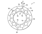
図2及び図3において、後半の工程(7)〜(13)は、モータ用のステータコア3(積層鉄心)を構成する鉄心薄板としてのステータコア片7(図5参照)を打ち抜き、それらを順次積層する工程を示している。このステータコア片7の打抜き工程では、順送り金型装置1の上金型に取り付けられたパンチP7〜P12及びこれらに対応して下金型に設けられたダイにより、(7)ステータコア片7のスロットS2の打抜き加工、(8)ステータコア片7における連結部位4をその連結状態を保持しつつ分割するための打抜き加工(半抜きおよびプッシュバック、または全抜きおよびプッシュバック)、(9)ステータコア3における計量用の鉄心薄板(すなわち、ステータコア3の最下層に位置する鉄心薄板)に対するかしめ計量穴C3の打抜き加工、(10)ステータコア片7の内形d2の打抜き加工(ティース部T2の形成)、(11)ステータコア片7における計量用以外の鉄心薄板に対するかしめ部C4の形成のための打抜き加工、(12)ステータコア片7の外形D2の打抜き加工、(13)打抜き後の鉄心薄板(連結状態にあるステータコア片7)の積層が順次実施される。なお、上記工程(1)〜(13)の間には、アイドルステージが適宜設定される。
2 and 3, in the latter half steps (7) to (13), the stator core piece 7 (see FIG. 5) as an iron core thin plate constituting the stator core 3 (laminated iron core) for the motor is punched, and these are sequentially laminated. The process to perform is shown. In the punching process of the
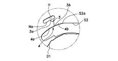
上記工程(8)は、図6にも示すように、ステータコア片7における連結部位4を分割線5に沿って分割する分割工程である。分割線5は、概ね径方向に延在し、その外側端部5aが分割補助穴Hの内縁Haと交差するとともに、その内側端部5bがスロットS2の外縁S2aと交差するように配置される。ステータコア片7は、図5にも示すように、第1及び第2の分割鉄心片7a、7bから構成される。ステータコア片7における連結部位4は、周方向に突出する凸部21を有する第1の分割鉄心片7aの第1連結端部4aと、この凸部21に対応する補完的形状をなす凹部22を有する第2の分割鉄心片7bの第2連結端部4bにそれぞれ分割され、これらの嵌合により、2つの分割鉄心片7a、7bが相互に連結される。
The step (8) is a dividing step of dividing the connecting
また、工程(8)では、図7に示すように、ステータコア片7における連結部位4を分割するための分割用パンチP8のパンチ動作を選択的に実行するためのカム機構31が設けられている。カム機構31は、カム部材32と、このカム部材32をパンチプレート(図示せず)の上面において水平方向にスライドさせる駆動装置33とを有している。カム部材32の底面(カム面)32aには、分割用パンチP8の上端部81を収容可能な凹部34が設けられている。図7(A)に示すように、分割用パンチP8の上端部81がカム部材32の凹部34に収容された状態では、分割用パンチP8の先端部82は、打抜き時(下降時)に第1の打抜き位置(半抜き位置)まで到達し、後述する半抜き加工が実施される。一方、カム部材32が水平(図7(A)中の左方)に移動し、図7(B)に示すように、分割用パンチP8の上端部81が凹部34から脱出してカム部材32の底面32aに当接した状態となると、分割用パンチP8の先端部82は、打抜き時(下降時)に第2の打抜き位置(全抜き位置)まで到達し、後述する全抜き(切断)加工が実施される。
Further, in step (8), as shown in FIG. 7, a
より詳細には、工程(8)において、分割用パンチP8が半抜き加工(第2連結部打抜き工程)を実施する場合には、図8(A)に示すように、分割用パンチP8の先端部82の下降をフープ材Wの板厚の途中の第1の打抜き位置で停める動作が実行される。このとき、図8(B)にも示すように、連結部位4には、半抜き加工により下方に突出した半抜き片(切起こし片)40が形成される。その後、下方に突出した半抜き片40が、下金型(図示せず)において分割用パンチP8に対向するように上方にばね付勢された押圧板41によりプッシュバックされる(すなわち、半抜き片40がフープ材Wにおける元の位置に嵌め込まれるように押し戻される)。これにより、半抜き領域10の左右側縁(すなわち、分割線5の両端に連なる部位)10a,10bは、スロットS2の外縁S2aおよび分割補助穴Hの内縁Haにおける元の位置に戻る。
More specifically, in the step (8), when the dividing punch P8 performs the half punching process (second connecting portion punching step), as shown in FIG. The operation of stopping the lowering of the
一方、工程(8)において、分割用パンチP8が全抜き加工(第1連結部打抜き工程)を実施する場合には、図9に示すように、分割用パンチP8の先端部82を、フープ材Wの板厚を超える第2の打抜き位置まで下降させる動作が実行される。このとき、連結部位4には、分割線5(図6参照)において完全に分離された全抜き片(切起こし片)45が形成される。その後、半抜き加工の場合と同様に、下方に突出した全抜き片45が、押圧板41によりプッシュバックされる。
On the other hand, in the step (8), when the dividing punch P8 performs the complete punching process (first connecting portion punching step), as shown in FIG. 9, the
このように、ステータコア片7における連結部位4に全抜き加工を施した場合には、連結部位4に半抜き加工を施した場合と比べて、ステータコア片7における連結部位4の連結力(ここで、引張り強さ)が低くなる(すなわち、ステータコア片7を構成する分割鉄心片7a、7bを相互に分離し易くなる)。つまり、工程(8)において、分割用パンチP8のパンチ動作に基づき、半抜き加工および全抜き加工を選択的に実施することにより、順送り金型装置1では、ステータコア片7における連結部位4の連結力を変更した2種のステータコア片7(第1及び第2の鉄心薄板)が打抜かれる。
As described above, when the connecting
この分割用パンチP8のパンチ動作は、製造された1つのステータコア3において、半抜き加工がなされたステータコア片7および全抜き加工がなされたステータコア片7をそれぞれ少なくとも1層以上含むように選択的に実行される。例えば、図10に示すように、1つのステータコア3において、最下層のステータコア片7(図10中に色付で示す)のみに半抜き加工を施し、残りの上部のステータコア片7の全てに全抜き加工を施す構成が可能である。逆に、最上層のステータコア片7のみに半抜き加工を施してもよい。これにより、製造後のステータコア3を分離する際に、分割鉄心片7a、7b間の連結力の高い最上層または最下層のステータコア片7に高いせん断力を容易に生じさせることができ、これにより、ステータコア3の分離が容易となる。
The punching operation of the dividing punch P8 is selectively performed in the manufactured
ただし、ステータコア3における半抜き加工がなされたステータコア片7および全抜き加工がなされたステータコア片7の配置および数量は、種々の変更が可能であり、それらの変更により、ステータコア3における連結部位4の連結力を容易に変更することができる。また、ここでは、半抜き加工および全抜き加工を施した2種のステータコア片7を打ち抜く例を示したが、これに限らず、例えば、カム機構31の構成を変更して程度の異なる半抜き加工(すなわち、分割用パンチP8の先端部82の第1の打抜き位置が異なる半抜き加工)を実施可能とすることにより、連結部位4の連結力を変更した2種のステータコア片7を打ち抜く構成としてもよい。
However, the arrangement and quantity of the
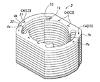
上記工程(13)では、工程(12)において打抜かれたステータコア片7が、順送り金型装置1における図示しないダイ内に順次積層され、さらに、ダイ下部のスクイズリング内へと順次押し込まれる。これにより、上下に隣接するステータコア片7同士が密接し、計量用のステータコア片7に形成されたかしめ計量穴C3および計量用以外のステータコア片7に形成されたかしめ部C4が鉄心薄板間で互いに係合することで、図10に示すように、所定枚のステータコア片7が互いに固着された積層体としてステータコア3が形成される。なお、工程(13)では、各ステータコア片7を所定の角度ずつ回転させて転積したり、ステータコア片7に所定のスキュー角を付与して積層したりすることも可能である。
In the step (13), the
このように、上記順送り金型装置1およびこれによるステータコア3の製造方法においては、周方向に相互に連結される複数の分割鉄心片7a、7bから構成されるステータコア3において、少なくとも一部のステータコア片7(第1の鉄心薄板)における連結部位4を他のステータコア片7(第2の鉄心薄板)における連結部位よりも分離容易に設ける(すなわち、分割鉄心片7a、7b間の連結力が互いに異なる2種のステータコア片7を積層する)ため、半抜き加工されたステータコア片7および全抜き加工されたステータコア片7の数(構成比率)や配置によってステータコア3における連結部位4(全体)の連結力を容易に調整することが可能となる。一般に、積層鉄心では、その用途によって鉄心薄板の形状、積層枚数、及び厚さなどが様々であるため、同一構成の鉄心薄板における連結部位の形状の変更により各分割鉄心片間の連結力を調整することは非常に困難であるが、上記順送り金型装置1およびそれによる製造方法では、分割鉄心片間の連結力が互いに異なる2種のステータコア片7の配置や枚数を調整するだけでよい。
Thus, in the
図11はステータコア3における連結部位4の分割形状の変形例を示す平面図である。ステータコア3における連結部位4の分割形状(分割線5の形状)については、図5等に示したものに限らず種々の変更が可能である。特に、図11に示すように、分割線5を直線状とする連結部位4の分割形状を採用するとよい。これにより、分割鉄心片7a、7bの第1連結端部4aおよび第2連結端部4bにおける歪みおよび応力集中や、ステータコア3の性能低下(鉄損増加)などを抑制しつつ、製造後のステータコア3における各ステータコア片7が意図せずに分離することを防止することが可能となる。
FIG. 11 is a plan view showing a modified example of the divided shape of the connecting
なお、上述の例では、連結部位4の連結力を変更した(すなわち、半抜き加工または全抜き加工が施された)2種のステータコア片7において、分割線5を同一形状としたが、連結部位4の打抜き加工を同一工程で実施しない場合には、分割線5が互いに異なる構成も可能である。
In the above-described example, the
また、ステータコア3の全体形状(全体の外形、ティース部、及びヨーク部等の各部形状ならびにステータコア片7の分割位置および分割数など)についても種々の変更が可能であり、例えば、後述する図15および図16に示すように、1つのステータコア片7が1つのティース部T2を有する構成も可能である。
Various changes can be made to the overall shape of the stator core 3 (the overall external shape, the shape of each part such as the teeth portion and the yoke portion, the division position and the number of divisions of the
(第2実施形態)
図12は本発明の第2実施形態に係る順送り金型装置1およびそのストリップレイアウトの一部を示す説明図であり、図13はステータコア3におけるステータコア片7の連結部を示す平面図であり、図14は図13に示したステータコア片7における連結部位の変形例を示す平面図である。図13は、上述の第1実施形態における図2に対応する図である。なお、図13及び図14において第1実施形態と同様の構成要素については、同一の符号が付されている。また、第2実施形態に関し、以下で特に言及しない事項については、上述の第1実施形態の場合と同様として詳細な説明を省略する。(Second Embodiment)
FIG. 12 is an explanatory view showing a part of the
第2実施形態に係る順送り金型装置1およびステータコア3の製造方法では、第1実施形態における工程(7)の前工程として、(8a)パンチP8aによる連結部位4の切欠き用穴Kの打ち抜き加工(工程(8a))が追加される。このパンチP8aには、上述の第1実施形態におけるカム機構31と同様のカム機構が付設されており、パンチP8aのパンチ動作は選択的に実行される。ただし、ここでは、パンチP8aの打抜き加工が実行されるか否かが選択される。また、工程(7)の後工程として、第1実施形態における工程(8)と同様のパンチP8bによるステータコア片7における連結部位4を分割するための打抜き加工(工程(8b))が実施される。ただし、ここでは、パンチP8bは全抜き加工(または半抜き加工)のみを実施し、カム機構によりパンチP8bの全抜き加工が実行されるか否かが選択される。
In the method of manufacturing the
上記工程(8a)では、切欠き用穴Kの打ち抜き加工により、図13に示すように、ステータコア片7の連結部位4の内周縁から外周側に向けて延在するスリット51が形成される。スリット51は、例えば、周方向の幅を約1mmに設定され、また、略半円状をなす先端部51aと連結部位4の外周縁との間の領域(以下、「幅狭部52」という。)の長さが約0.5〜1.0mm程度に設定される。このように、スリット51の形成により連結部位4の幅(最小幅)を他の部位(ステータコア片7の外周縁部)の幅よりも狭くすることで、連結部位4の分離が容易となる(すなわち、連結力を低下させることができる)。
In the step (8a), the
この工程(8a)は、上述の第1実施形態における半抜き加工(または全抜き加工)の代わりに実施することが可能である。つまり、1つのステータコア3において、切欠き用穴Kが形成されたステータコア片7および切欠き用穴Kが形成されていないステータコア片7をそれぞれ少なくとも1層以上含むように選択的に実行される。一方、工程(8b)では、工程(8a)で切欠き用穴Kが形成されていないステータコア片7に対し、全抜き加工(または半抜き加工)が実施される。これにより、図13中に想像線で示すように、切欠き用穴Kが形成されていない他のステータコア片7については、上記スリット51に対応する位置(ロータコア2の軸方向において重なる位置)において、凸部21および凹部22に分割された連結部位4が形成される。このように、1つのステータコア3を構成する一部のステータコア片7における連結部位4に対して幅狭部52を形成する一方、残りのステータコア片7における連結部位4に上述の第1実施形態と同様の全抜き加工(または半抜き加工)を実施することにより、第1実施形態と同様に分割鉄心片7a、7b間の連結力が互いに異なる2種のステータコア片7を積層することが可能となる。なお、幅狭部52に上述のような分割線5が形成された構成も可能である。
This step (8a) can be carried out instead of the half blanking (or full blanking) in the first embodiment described above. That is, in one
したがって、第2実施形態に係る順送り金型装置1およびステータコア3の製造方法では、幅狭部52が形成されたステータコア片7および全抜き加工(または半抜き加工)されたステータコア片7の数(構成比率)や配置によってステータコア3における連結部位4(全体)の連結力を容易に調整することが可能となる。
Therefore, in the manufacturing method of the progressive
なお、工程(8a)で形成される切欠き用穴Kの形状については種々の変更が可能である。例えば、図14(A)に示すように、例えば、スリット51は、周方向の幅を約1mmに設定され、また、約2mmの直径を有する略円形の先端部51aを有する構成としてもよい。
Various changes can be made to the shape of the notch hole K formed in the step (8a). For example, as shown in FIG. 14A, for example, the
また、例えば、図14(B)に示すように、例えば、スリット51の開口端51bが最大の幅(例えば、2mm)を有するようにし、スリット51が外周側に向けて先細り状をなすように構成してもよい。この場合、先端部51aは、図13に示したものと同様に略半円状とすることができる。
Further, for example, as shown in FIG. 14B, for example, the opening
また、ここでは、工程(8a)を独立した工程として示したが、例えば、切欠き用穴Kをステータコア3の最下層の鉄心薄板にのみ形成する場合には、第1実施形態で説明したかしめ計量穴C3の打抜き加工(工程(9))と同時に切欠き用穴Kを形成することも可能である。
Here, the step (8a) is shown as an independent step. However, for example, when the notch hole K is formed only in the lowermost core thin plate of the
(第3実施形態)
図15及び図16は本発明の第3実施形態に係るステータコア片を示す平面図である。なお、図15及び図16において第1または第2実施形態と同様の構成要素については、同一の符号が付されている。また、第3実施形態に関し、以下で特に言及しない事項については、上述の第1または第2実施形態の場合と同様として詳細な説明を省略する。(Third embodiment)
15 and 16 are plan views showing a stator core piece according to the third embodiment of the present invention. In FIG. 15 and FIG. 16, the same components as those in the first or second embodiment are denoted by the same reference numerals. Further, regarding the third embodiment, matters not particularly mentioned below are the same as those in the first or second embodiment described above, and detailed description thereof is omitted.
上述の第1及び第2実施形態では、分割鉄心片7a、7b間の連結力が互いに異なる2種のステータコア片7を積層する順送り金型装置1およびステータコア3の製造方法について示したが、そのような2種のステータコア片7を積層する手法は、それらの実施形態に限定されるものではない。
In the first and second embodiments described above, the manufacturing method of the
例えば、図15及び図16に示すように連結部位4の形状が異なる2種のステータコア片7を形成するために、第1実施形態における工程(8)と同様の独立した2つの打抜き工程(第1及び第2連結部打抜き工程)を設けることが可能である。この場合、例えば、第1連結部打抜き工程において、図15に示す直線状の分割線5で連結部位4を分割するように打抜き加工を施す一方、第2連結部打抜き工程において、図16に示す湾曲した分割線5で連結部位4を分割するように打抜き加工を施し、周方向に突出する凸部21を有する第1の分割鉄心片7aの第1連結端部4aと、この凸部21に対応する補完的形状をなす凹部22を有する第2の分割鉄心片7bの第2連結端部4bとを形成することも可能である。
For example, as shown in FIGS. 15 and 16, in order to form two types of
このように、1つのステータコア3を構成する一部のステータコア片7における連結部位4に対して打抜き形状(ここでは、分割線5の形状)が異なる打抜き工程を設けることにより、第1及び第2実施形態と同様に、分割鉄心片7a、7b間の連結力が互いに異なる2種のステータコア片7を積層することが可能となる。
As described above, the first and second punching steps having different punching shapes (here, the shapes of the dividing lines 5) are provided for the
したがって、図15及び図16に示したステータコア片7の数(構成比率)や配置によってステータコア3における連結部位4(全体)の連結力を容易に調整することが可能となる。
Therefore, it becomes possible to easily adjust the connecting force of the connecting portion 4 (whole) in the
以上、本発明を特定の実施形態に基づいて説明したが、これらの実施形態はあくまでも例示であって、本発明はこれらの実施形態によって限定されるものではない。たとえば、上記実施形態では、連結部位の連結力が互いに異なる2種の鉄心薄板を用いる例を示したが、これに限らず、連結部位の連結力が互いに異なる3種以上の鉄心薄板を用いて積層鉄心を構成してもよい。また、上記実施形態では積層された鉄心薄板間をかしめ結合させる構成としたが、これに限らず、接着剤やレーザー溶接等によって鉄心薄板間を結合してもよい。なお、上記実施形態に示した本発明に係る積層鉄心の製造方法および積層鉄心の製造装置の各構成要素は、必ずしも全てが必須ではなく、少なくとも本発明の範囲を逸脱しない限りにおいて適宜取捨選択することが可能である。 As mentioned above, although this invention was demonstrated based on specific embodiment, these embodiment is an illustration to the last, Comprising: This invention is not limited by these embodiment. For example, in the said embodiment, although the example using 2 types of core thin plates from which a connection force of a connection part mutually differs was shown, using not only this but 3 or more types of iron core thin plates from which a connection force of a connection part differs from each other A laminated iron core may be configured. Moreover, although it was set as the structure which crimps | bonds between the laminated | stacked iron core thin plates in the said embodiment, you may couple | bond between iron core thin plates not only by this but by an adhesive agent or laser welding. Note that all the components of the method for manufacturing a laminated core and the apparatus for producing a laminated core according to the present invention shown in the above embodiments are not necessarily essential, and are appropriately selected as long as they do not depart from the scope of the present invention. It is possible.
1 順送り金型装置(積層鉄心の製造装置)
3 ステータコア(積層鉄心)
4 連結部位
4a 第1連結端部
4b 第2連結端部
5 分割線
7 ステータコア片(鉄心薄板)
31 カム機構
40 半抜き片
41 押圧板
45 全抜き片
51 スリット
P1−P12 パンチ1 Progressive die equipment (lamination core manufacturing equipment)
3 Stator core (laminated core)
4
31
Claims (9)
前記鉄心薄板は、第1の鉄心薄板および第2の鉄心薄板を含み、
前記帯状薄鋼板において、前記第1の鉄心薄板を構成する分割鉄心片間の連結部位をそれぞれ打抜き加工する第1連結部打抜き工程と、
前記帯状薄鋼板において、前記第2の鉄心薄板を構成する分割鉄心片間の連結部位をそれぞれ打抜き加工する第2連結部打抜き工程と、
前記第1の鉄心薄板および前記第2の鉄心薄板をそれぞれ少なくとも1以上積層して互いに結合させる積層工程と
を有し、
前記第1の鉄心薄板における前記分割鉄心片間の連結部位は、前記第2の鉄心薄板における前記分割鉄心片間の連結部位よりも分離容易に設けられていることを特徴とする分割型の積層鉄心の製造方法。A method of manufacturing a split-type laminated core by punching an iron sheet having a plurality of divided core pieces interconnected in the circumferential direction from a strip-shaped sheet and laminating a plurality of these core sheets.
The iron core thin plate includes a first iron core thin plate and a second iron core thin plate,
In the strip-shaped thin steel plate, a first connecting portion punching step for punching each connecting portion between the divided core pieces constituting the first iron core thin plate;
In the strip-shaped thin steel sheet, a second connecting portion punching step for punching each connecting portion between the divided core pieces constituting the second iron core thin plate;
A laminating step of laminating at least one or more of the first iron core thin plate and the second iron core thin plate and bonding them together.
The divisional type lamination characterized in that the connection portion between the divided core pieces in the first iron core thin plate is provided more easily than the connection portion between the division core pieces in the second iron core thin plate. Manufacturing method of iron core.
前記第2連結部打抜き工程では、前記第2の鉄心薄板における前記連結部位を第2分割線に沿って分割する半抜き加工が施されることを特徴とする請求項1に記載の分割型の積層鉄心の製造方法。In the first connecting portion punching step, a complete punching process is performed to divide the connecting portion in the first iron core thin plate along a first dividing line,
2. The split mold according to claim 1, wherein in the second connecting portion punching step, a half punching process is performed in which the connecting portion of the second iron core thin plate is split along a second dividing line. 3. Manufacturing method of laminated iron core.
前記第2連結部打抜き工程では、前記第2の鉄心薄板における前記連結部位にスリットを形成する打抜き加工が施されることを特徴とする請求項1に記載の分割型の積層鉄心の製造方法。In the first connecting portion punching step, a punching process for dividing the connecting portion in the first iron core thin plate along a first dividing line is performed,
2. The method for manufacturing a split-type laminated core according to claim 1, wherein in the second connecting portion punching step, a punching process is performed to form a slit at the connecting portion of the second iron core thin plate.
前記鉄心薄板は、第1の鉄心薄板および第2の鉄心薄板を含み、
前記帯状薄鋼板において、前記第1の鉄心薄板を構成する分割鉄心片間の連結部位をそれぞれ打抜き加工する第1連結部打抜き部と、
前記帯状薄鋼板において、前記第2の鉄心薄板を構成する分割鉄心片間の連結部位をそれぞれ打抜き加工する第2連結部打抜き部と、
前記第1の鉄心薄板および前記第2の鉄心薄板をそれぞれ少なくとも1以上積層して互いに結合させる積層部と
を備え、
前記第1の鉄心薄板における前記分割鉄心片間の連結部位は、前記第2の鉄心薄板における前記分割鉄心片間の連結部位よりも分離容易に設けられていることを特徴とする分割型の積層鉄心の製造方装置。An apparatus for manufacturing a split-type laminated core by punching out an iron core sheet having a plurality of divided core pieces interconnected in the circumferential direction from a strip-shaped sheet steel sheet, and laminating a plurality of these core sheets.
The iron core thin plate includes a first iron core thin plate and a second iron core thin plate,
In the strip-shaped thin steel plate, a first connecting portion punched portion for punching each of the connecting portions between the divided core pieces constituting the first iron core thin plate,
In the strip-shaped thin steel plate, a second connecting portion punched portion for punching a connecting portion between the divided core pieces constituting the second iron core thin plate, and
A laminated portion that laminates at least one or more of the first iron core thin plate and the second iron core thin plate, and couples them together;
The divisional type lamination characterized in that the connection portion between the divided core pieces in the first iron core thin plate is provided more easily than the connection portion between the division core pieces in the second iron core thin plate. Iron core manufacturing method equipment.
Applications Claiming Priority (1)
| Application Number | Priority Date | Filing Date | Title |
|---|---|---|---|
| PCT/JP2015/001448 WO2016147214A1 (en) | 2015-03-16 | 2015-03-16 | Method for manufacturing laminated iron core and device for manufacturing laminated iron core |
Publications (2)
| Publication Number | Publication Date |
|---|---|
| JPWO2016147214A1 JPWO2016147214A1 (en) | 2017-12-28 |
| JP6400833B2 true JP6400833B2 (en) | 2018-10-03 |
Family
ID=56918455
Family Applications (1)
| Application Number | Title | Priority Date | Filing Date |
|---|---|---|---|
| JP2017505742A Active JP6400833B2 (en) | 2015-03-16 | 2015-03-16 | Laminated core manufacturing method and laminated core manufacturing apparatus |
Country Status (5)
| Country | Link |
|---|---|
| US (1) | US10587172B2 (en) |
| EP (1) | EP3273580B1 (en) |
| JP (1) | JP6400833B2 (en) |
| CN (1) | CN107408872B (en) |
| WO (1) | WO2016147214A1 (en) |
Families Citing this family (10)
| Publication number | Priority date | Publication date | Assignee | Title |
|---|---|---|---|---|
| WO2018008328A1 (en) * | 2016-07-08 | 2018-01-11 | 日創電機株式会社 | Motor stator, motor stator manufacturing method, and motor |
| JP7137918B2 (en) * | 2017-10-16 | 2022-09-15 | 株式会社三井ハイテック | Laminated core manufacturing method |
| WO2019200339A1 (en) * | 2018-04-13 | 2019-10-17 | Ipg Photonics Corporation | Laser assisted machining of sheet material |
| US20210399594A1 (en) * | 2018-12-17 | 2021-12-23 | Nippon Steel Corporation | Laminated core and electric motor |
| EP3736062A1 (en) | 2019-05-08 | 2020-11-11 | voestalpine Stahl GmbH | Method for stamp packaging of metal parts to stacks of metal sheets |
| DE102020125897A1 (en) * | 2020-10-02 | 2022-04-07 | Vacuumschmelze Gmbh & Co. Kg | Laminated core, electrical machine and method for manufacturing a laminated core |
| CN112366905B (en) * | 2021-01-11 | 2021-03-19 | 宁波震裕科技股份有限公司 | Manufacturing process of motor stator with locally separated tooth yoke |
| WO2023182257A1 (en) * | 2022-03-24 | 2023-09-28 | ニデック株式会社 | Stator core manufacturing method, stator core, and motor |
| WO2023182256A1 (en) * | 2022-03-24 | 2023-09-28 | ニデック株式会社 | Stator core manufacturing method, stator core, and motor |
| CN114453482B (en) * | 2022-04-12 | 2022-07-01 | 宁波震裕科技股份有限公司 | Manufacturing process of iron core |
Family Cites Families (6)
| Publication number | Priority date | Publication date | Assignee | Title |
|---|---|---|---|---|
| JPH0998545A (en) * | 1995-09-29 | 1997-04-08 | Mitsubishi Electric Corp | Motor-driven blower and its manufacture |
| JP5189915B2 (en) | 2008-07-14 | 2013-04-24 | 株式会社大一商会 | Game machine |
| JP5311276B2 (en) | 2008-07-17 | 2013-10-09 | 日立工機株式会社 | Electric tool |
| JP2010178487A (en) * | 2009-01-29 | 2010-08-12 | Kuroda Precision Ind Ltd | Manufacturing method for laminated core and forward metal mold device |
| JP5773926B2 (en) | 2012-03-27 | 2015-09-02 | 三菱電機株式会社 | Laminated stator core, laminated stator, laminated stator manufacturing method |
| JP5814304B2 (en) * | 2013-06-21 | 2015-11-17 | 黒田精工株式会社 | Laminated iron core manufacturing apparatus and laminated iron core manufacturing method |
-
2015
- 2015-03-16 JP JP2017505742A patent/JP6400833B2/en active Active
- 2015-03-16 CN CN201580077641.XA patent/CN107408872B/en active Active
- 2015-03-16 EP EP15885314.3A patent/EP3273580B1/en active Active
- 2015-03-16 US US15/556,894 patent/US10587172B2/en active Active
- 2015-03-16 WO PCT/JP2015/001448 patent/WO2016147214A1/en active Application Filing
Also Published As
| Publication number | Publication date |
|---|---|
| EP3273580A1 (en) | 2018-01-24 |
| WO2016147214A1 (en) | 2016-09-22 |
| EP3273580B1 (en) | 2021-12-08 |
| CN107408872A (en) | 2017-11-28 |
| EP3273580A4 (en) | 2018-11-14 |
| CN107408872B (en) | 2019-07-26 |
| JPWO2016147214A1 (en) | 2017-12-28 |
| US20180026501A1 (en) | 2018-01-25 |
| US10587172B2 (en) | 2020-03-10 |
Similar Documents
| Publication | Publication Date | Title |
|---|---|---|
| JP6400833B2 (en) | Laminated core manufacturing method and laminated core manufacturing apparatus | |
| JP6401466B2 (en) | Laminated iron core and method for manufacturing the same | |
| JP5583391B2 (en) | Stator laminated core | |
| JP5719979B1 (en) | Laminated iron core manufacturing apparatus and laminated iron core manufacturing method | |
| JP5379522B2 (en) | Manufacturing method of split core pieces | |
| EP2445086B1 (en) | Stator core and method for manufacturing same | |
| JP2008113529A (en) | Laminated core and manufacturing method therefor | |
| WO2012114577A1 (en) | Method of manufacturing stator core, and stator core | |
| WO2019066032A1 (en) | Production method for core for rotary electric machine | |
| JP2010178487A (en) | Manufacturing method for laminated core and forward metal mold device | |
| JP5688919B2 (en) | Manufacturing method of laminated iron core | |
| JP2015080412A5 (en) | ||
| JP2017208986A (en) | Method for manufacturing laminated iron core for rotary electric machine | |
| JP5248972B2 (en) | Method for manufacturing laminated iron core and mold apparatus | |
| JP2011254699A (en) | Method and device for manufacturing lamination core | |
| JP5697640B2 (en) | Laminated core manufacturing method and laminated core manufacturing apparatus | |
| JP6045638B2 (en) | Manufacturing method of laminated iron core | |
| JP2008113498A (en) | Laminated iron core, and manufacturing method therefor | |
| JP2008278753A (en) | Method of manufacturing laminated core and metal mold device | |
| JP4578460B2 (en) | Manufacturing method of stator laminated iron core | |
| JP4991885B2 (en) | Manufacturing method of laminated iron core | |
| JP6316783B2 (en) | Manufacturing method and manufacturing apparatus of laminated iron core | |
| JP5039473B2 (en) | Method and apparatus for manufacturing split laminated iron core | |
| JP6586286B2 (en) | Manufacturing method of laminated iron core |
Legal Events
| Date | Code | Title | Description |
|---|---|---|---|
| A621 | Written request for application examination |
Free format text: JAPANESE INTERMEDIATE CODE: A621 Effective date: 20171129 |
|
| TRDD | Decision of grant or rejection written | ||
| A01 | Written decision to grant a patent or to grant a registration (utility model) |
Free format text: JAPANESE INTERMEDIATE CODE: A01 Effective date: 20180821 |
|
| A61 | First payment of annual fees (during grant procedure) |
Free format text: JAPANESE INTERMEDIATE CODE: A61 Effective date: 20180905 |
|
| R150 | Certificate of patent or registration of utility model |
Ref document number: 6400833 Country of ref document: JP Free format text: JAPANESE INTERMEDIATE CODE: R150 |
|
| R250 | Receipt of annual fees |
Free format text: JAPANESE INTERMEDIATE CODE: R250 |
|
| R250 | Receipt of annual fees |
Free format text: JAPANESE INTERMEDIATE CODE: R250 |
|
| R250 | Receipt of annual fees |
Free format text: JAPANESE INTERMEDIATE CODE: R250 |