JP6399459B2 - Nebulizer with coding means - Google Patents
Nebulizer with coding means Download PDFInfo
- Publication number
- JP6399459B2 JP6399459B2 JP2015504880A JP2015504880A JP6399459B2 JP 6399459 B2 JP6399459 B2 JP 6399459B2 JP 2015504880 A JP2015504880 A JP 2015504880A JP 2015504880 A JP2015504880 A JP 2015504880A JP 6399459 B2 JP6399459 B2 JP 6399459B2
- Authority
- JP
- Japan
- Prior art keywords
- nebulizer
- coding means
- coding
- housing part
- housing
- Prior art date
- Legal status (The legal status is an assumption and is not a legal conclusion. Google has not performed a legal analysis and makes no representation as to the accuracy of the status listed.)
- Active
Links
Images


Classifications
-
- A—HUMAN NECESSITIES
- A61—MEDICAL OR VETERINARY SCIENCE; HYGIENE
- A61M—DEVICES FOR INTRODUCING MEDIA INTO, OR ONTO, THE BODY; DEVICES FOR TRANSDUCING BODY MEDIA OR FOR TAKING MEDIA FROM THE BODY; DEVICES FOR PRODUCING OR ENDING SLEEP OR STUPOR
- A61M11/00—Sprayers or atomisers specially adapted for therapeutic purposes
- A61M11/006—Sprayers or atomisers specially adapted for therapeutic purposes operated by applying mechanical pressure to the liquid to be sprayed or atomised
- A61M11/007—Syringe-type or piston-type sprayers or atomisers
-
- A—HUMAN NECESSITIES
- A61—MEDICAL OR VETERINARY SCIENCE; HYGIENE
- A61M—DEVICES FOR INTRODUCING MEDIA INTO, OR ONTO, THE BODY; DEVICES FOR TRANSDUCING BODY MEDIA OR FOR TAKING MEDIA FROM THE BODY; DEVICES FOR PRODUCING OR ENDING SLEEP OR STUPOR
- A61M11/00—Sprayers or atomisers specially adapted for therapeutic purposes
- A61M11/02—Sprayers or atomisers specially adapted for therapeutic purposes operated by air or other gas pressure applied to the liquid or other product to be sprayed or atomised
-
- A—HUMAN NECESSITIES
- A61—MEDICAL OR VETERINARY SCIENCE; HYGIENE
- A61M—DEVICES FOR INTRODUCING MEDIA INTO, OR ONTO, THE BODY; DEVICES FOR TRANSDUCING BODY MEDIA OR FOR TAKING MEDIA FROM THE BODY; DEVICES FOR PRODUCING OR ENDING SLEEP OR STUPOR
- A61M16/00—Devices for influencing the respiratory system of patients by gas treatment, e.g. mouth-to-mouth respiration; Tracheal tubes
- A61M16/20—Valves specially adapted to medical respiratory devices
-
- A—HUMAN NECESSITIES
- A61—MEDICAL OR VETERINARY SCIENCE; HYGIENE
- A61M—DEVICES FOR INTRODUCING MEDIA INTO, OR ONTO, THE BODY; DEVICES FOR TRANSDUCING BODY MEDIA OR FOR TAKING MEDIA FROM THE BODY; DEVICES FOR PRODUCING OR ENDING SLEEP OR STUPOR
- A61M2205/00—General characteristics of the apparatus
- A61M2205/27—General characteristics of the apparatus preventing use
-
- A—HUMAN NECESSITIES
- A61—MEDICAL OR VETERINARY SCIENCE; HYGIENE
- A61M—DEVICES FOR INTRODUCING MEDIA INTO, OR ONTO, THE BODY; DEVICES FOR TRANSDUCING BODY MEDIA OR FOR TAKING MEDIA FROM THE BODY; DEVICES FOR PRODUCING OR ENDING SLEEP OR STUPOR
- A61M2205/00—General characteristics of the apparatus
- A61M2205/60—General characteristics of the apparatus with identification means
- A61M2205/6036—General characteristics of the apparatus with identification means characterised by physical shape, e.g. array of activating switches
-
- A—HUMAN NECESSITIES
- A61—MEDICAL OR VETERINARY SCIENCE; HYGIENE
- A61M—DEVICES FOR INTRODUCING MEDIA INTO, OR ONTO, THE BODY; DEVICES FOR TRANSDUCING BODY MEDIA OR FOR TAKING MEDIA FROM THE BODY; DEVICES FOR PRODUCING OR ENDING SLEEP OR STUPOR
- A61M2205/00—General characteristics of the apparatus
- A61M2205/60—General characteristics of the apparatus with identification means
- A61M2205/6045—General characteristics of the apparatus with identification means having complementary physical shapes for indexing or registration purposes
Description
本発明は、請求項1の前提部に記載されたネブライザ及び請求項25の前提部に記載されたかかるネブライザのためのハウジング状コンポーネントに関する。
The invention relates to a nebulizer according to the preamble of
本発明の出発点は、基本的形態が国際公開第91/14468(A1)号パンフレットに記載されると共に特定の実施形態が国際公開第97/12687(A1)号パンフレット(図6a及び図6b)に記載され且つ添付の図面の図1及び図2に記載されている吸入器の形態をしたベーリンガ・インゲルハイム・ケーゲー(Boehringer Ingelheim KG )製の「レスピマット(Respimat)」という商品名で市販されているネブライザに関する。ネブライザは、噴霧化されるべき流体のリザーバとして、流体の入った挿入可能な容器及び流体を送り出して噴霧化するための駆動ばねを備えた圧力発生器を有している。 The starting point of the present invention is that the basic form is described in the pamphlet of WO 91/14468 (A1) and the specific embodiment is pamphlet of WO 97/12687 (A1) (FIGS. 6a and 6b). Marketed under the name “Respimat” by Boehringer Ingelheim KG in the form of an inhaler as described in FIGS. 1 and 2 of the accompanying drawings. Related to the nebulizer. The nebulizer has, as a reservoir for the fluid to be nebulized, an insertable container containing the fluid and a pressure generator with a drive spring for delivering and nebulizing the fluid.
本願の開示内容を補完するため、予備的に、国際公開第91/14468(A1)号パンフレットと国際公開第97/12687(A1)号パンフレットの両方の開示内容全体を参照されたい。一般に、これら特許文献の開示内容は、好ましくは、流体に加わるばね圧力が5〜60mPa、好ましくは10〜50mPa、作動一回当たりの流体の量が10〜50μl、好ましくは10〜20μl、最も好ましくは約15μl、粒径が最高20μmまで、好ましくは3〜10μmのネブライザに関する。 To supplement the disclosure content of this application, please refer to the entire disclosure content of both WO 91/14468 (A1) and WO 97/12687 (A1). In general, the disclosure of these patent documents is preferably that the spring pressure applied to the fluid is 5-60 mPa, preferably 10-50 mPa, the amount of fluid per actuation is 10-50 μl, preferably 10-20 μl, most preferably Relates to a nebulizer of about 15 μl and a particle size up to 20 μm, preferably 3-10 μm.
さらに、これら特許文献の開示内容は好ましくは、長さが約9cm〜約15cm、幅が約2cm〜約5cmの筒体の形をしていて、ノズルスプレー円錐角が20°〜160°、好ましくは80°〜100°のネブライザに関する。これらの値は、本発明の教示による吸入器にとって特に好ましい値とみなされる。 Further, the disclosures of these patent documents are preferably in the form of a cylinder having a length of about 9 cm to about 15 cm, a width of about 2 cm to about 5 cm, and a nozzle spray cone angle of 20 ° to 160 °, preferably Relates to a nebulizer of 80 ° to 100 °. These values are considered particularly preferred values for an inhaler according to the teachings of the present invention.
ネブライザの下側ハウジング部品の形態をした作動部材を回転させることにより、駆動ばねを引っ張ることができ、そして流体を圧力発生器の圧力チャンバ内に吸い込むことができる。制止要素の手動作動後、圧力チャンバ内の流体は、駆動ばねによって圧力下に置かれ、そして噴霧化され、即ち、排出されてエーロゾルが形成される。片手での引っ張り操作中及びもう一方の手での次の噴霧化中、容器は、作動運動を行う。 By rotating the actuating member in the form of the lower housing part of the nebulizer, the drive spring can be pulled and fluid can be drawn into the pressure chamber of the pressure generator. After manual actuation of the stop element, the fluid in the pressure chamber is placed under pressure by a drive spring and is atomized, i.e. discharged to form an aerosol. During the pulling operation with one hand and during the next nebulization with the other hand, the container performs an actuation movement.
ネブライザは、ネブライザの作動回数をカウントするために作動部材の回転を検出する機械式モニタ装置を有する。 The nebulizer has a mechanical monitoring device that detects the rotation of the actuation member in order to count the number of actuations of the nebulizer.
公知のネブライザでは、容器は、互いに異なる流体、即ち、特に互いに異なる薬剤又は有効物質を収容した状態で用いられる場合がある。かかるネブライザ及びかかるネブライザのための容器を使用中における容器との混同から効果的に守るため、国際公開第2005/080002(A1)号パンフレットは、改良型ネブライザ及び改良型容器を提案した。 In known nebulizers, the container may be used with different fluids, i.e. in particular containing different drugs or active substances. In order to effectively protect such nebulizers and containers for such nebulizers from being confused with the containers in use, WO 2005/080002 (A1) pamphlet has proposed improved nebulizers and improved containers.
基本的な改良点は、特定の容器のみ又は多数個の特定の容器を用いることができるよう、特にこれら容器向きのネブライザ内に挿入することができるようコード付けを提供することであった。この目的のため、ネブライザは、第1のコード付け手段を有し、第2のコード付け手段が容器と関連している。コード付け手段は、コード付け手段が合致した場合又は合致するコード付けを形成した場合にのみ第2のコード付け手段と関連した容器をネブライザ内に挿入することができ又はネブライザに使用することができるよう互いに協働する。 The basic improvement was to provide coding so that only specific containers or a number of specific containers could be used, particularly for insertion into nebulizers intended for these containers. For this purpose, the nebulizer has a first coding means and a second coding means is associated with the container. The coding means can insert the container associated with the second coding means into the nebulizer or be used in the nebulizer only if the coding means is matched or forms a matching coding. Cooperate with each other.
この国際公開パンフレットは、上述の請求項の前提部を構成する本発明の直接的な出発点をなしているので、本願の開示内容を補完するため、本明細書の完全な開示内容も又念のために参照されたい。 Since this international pamphlet is a direct starting point of the present invention that constitutes the premise of the above-mentioned claims, the complete disclosure of the present specification is also considered in order to complement the disclosure of the present application. Please refer for.
公知のネブライザ並びに本発明のネブライザは、純粋に機械的に、即ち、推進ガスなしでしかも電気系統なしで動作する。 The known nebulizers as well as the nebulizers of the invention operate purely mechanically, i.e. without propellant gas and without an electrical system.
好ましくは、コード付けも又純粋に機械的に動作すると共に働き、その結果、コード付けを簡単且つ安価な仕方でしかも高度の動作上の信頼性を持った状態で提供することができる。 Preferably, the coding also works and works purely mechanically, so that coding can be provided in a simple and inexpensive manner and with a high degree of operational reliability.
先行技術によれば、作動的に互いに連結された相補コード付け手段は、これまで、特定のコード付けしか提供することができない。 According to the prior art, complementary coding means operatively connected to each other so far can only provide specific coding.
異なるコード付けを作るためには、ネブライザとハウジング状コンポーネントの両方について互いに異なるコード付け手段を用いることが必要である。 In order to produce different coding, it is necessary to use different coding means for both the nebulizer and the housing-like component.
本発明は、コード付けオプションが改良されたネブライザ又はかかるネブライザのためのハウジング取り付けコンポーネントに関する課題に基づいている。 The present invention is based on the problem of nebulizers with improved coding options or housing mounting components for such nebulizers.
この課題は、請求項1記載のネブライザ又は請求項25記載のハウジング状コンポーネントによって解決される。本発明の有利な実施形態又は別の特徴は、それぞれの従属形式の請求項の内容から導き出せる。
This problem is solved by a nebulizer according to
したがって、本発明は、当初、流体のためのネブライザであって、流体の入った容器をネブライザ中に挿入することができ、ネブライザは、流体を運搬すると共に/或いは噴霧化する圧力発生器を有し、ネブライザは、好ましくは、容器の挿入を可能にするよう取り外し可能なハウジング部品を備え、コード付け手段が設けられ、コード付け手段は、コード付け手段が合致するコードを有する場合にのみネブライザ中に挿入することができ又はネブライザと共に使用することができるよう互いに協働する形式のネブライザから出発している。 Accordingly, the present invention is initially a nebulizer for fluid, in which a container containing fluid can be inserted into the nebulizer, the nebulizer having a pressure generator that carries and / or atomizes the fluid. However, the nebulizer preferably comprises a removable housing part to allow insertion of the container and provided with coding means, the coding means being only in the nebulizer if the coding means has a matching cord Starting from a type of nebulizer that cooperates with each other so that it can be inserted into or used with a nebulizer.
今や、本発明によれば、コード付け手段のうちの少なくとも1つは、互いに異なる規定された位置に取り付け可能であり、コード付け手段が互いに合致する各位置で異なるコードが得られる、又は各位置で異なるコードを得ることによりネブライザ、容器及び/又はハウジング部品のコードが設定される。 Now according to the invention, at least one of the coding means can be mounted at different defined positions from each other, and a different code is obtained at each position where the coding means match each other, or each position The code for the nebulizer, container and / or housing part is set by obtaining a different code.
提案した解決手段により、コードを変更することが望ましい場合、コード付け手段の全てを置き換え又は再設計する必要なく、考えられるコードの生成の面で実質的に多大な融通性が得られる。その結果、ネブライザ内における種々の有効物質の使用、流体中の有効物質の互いに異なる濃度及び/又は或る特定のレベルまでの容器への流体の追加量にもかかわらず、互いに異なる形態のコード付け手段の提供は回避できる。 With the proposed solution, if it is desired to change the code, there is substantially great flexibility in terms of the possible code generation without having to replace or redesign all of the coding means. As a result, different forms of coding despite the use of different active substances in the nebulizer, different concentrations of active substance in the fluid and / or the additional amount of fluid to the container to a certain level. Provision of means can be avoided.
かくして、コード付け手段に関し、本発明は、キャリーオーバ部品に関する技術的思想に移っている。 Thus, with respect to the coding means, the invention has moved on to the technical idea of carryover parts.
本発明の第1の実施形態によれば、コード付け手段のうちの少なくとも1つは、互いに異なる規定された位置でネブライザに取り付け可能であり、コード付け手段のうちの他の少なくとも1つは、互いに異なる規定された位置で取り外し可能なハウジング部品に取り付け可能であり又は取り外し可能なハウジング部品に少なくとも交換可能に取り付けできる。このように、高い比率のキャリーオーバ部品の実現を達成しながら比較的多数の考えられるコードを得ることができる。 According to a first embodiment of the invention, at least one of the coding means can be attached to the nebulizer at a defined position different from each other, and at least one other of the coding means is It can be attached to the removable housing part in different defined positions from each other or at least replaceably attached to the removable housing part. In this way, a relatively large number of possible codes can be obtained while achieving a high proportion of carryover parts.
少なくとも、コード付け手段を取り外し可能なハウジング部品に元通りに取り付けることができるということは、異なるコード付けの必要がある場合、取り外し可能なハウジング部品全体を再構成する必要はなく、コード付け手段を交換するだけで済むということを意味している。 At least that the coding means can be reattached to the removable housing part, so that if there is a need for different coding, the entire removable housing part need not be reconfigured, It means that you only need to replace it.
本発明の技術的思想の別の実施形態によれば、取り外し可能なハウジング部品と関連した少なくとも1つのコード付け手段とネブライザと関連した他の少なくとも1つのコード付け手段の両方を互いに異なる規定された位置に取り付けることができる。このようにすると、比較的最も高い融通性を達成することが可能である。 According to another embodiment of the inventive concept, at least one coding means associated with the removable housing part and at least one other coding means associated with the nebulizer are both defined differently. Can be attached in position. In this way, it is possible to achieve the highest flexibility.
それと同時に、好都合には、コード付けが整合していない場合、少なくとも、容器は、完全に挿入されるのが阻止され、特に、流体が圧力発生器又は運搬管と接触することは、不可能である。 At the same time, advantageously, if the coding is not aligned, at least the container is prevented from being fully inserted and in particular it is impossible for the fluid to contact the pressure generator or the conveying tube. is there.
上述したように、コード付け手段は、好ましくは、構成を簡単にするという理由及び信頼性の理由で互いに機械的に協働する。 As mentioned above, the coding means preferably cooperate mechanically with each other for reasons of simplicity and reliability.
コード付け手段は、次に且つ/或いはコード付け手段を次に且つ/或いは専用工具だけを用いてコード付け手段を解除することができるような仕方でネブライザに取り付けられるのがよく又は取り付けられる。これは、一方において、融通性を高め、他方において、取り扱いを可能にすることを意図している。 The coding means may or may not be attached to the nebulizer in such a way that the coding means can then be released and / or only with a dedicated tool. This is intended on the one hand to increase flexibility and on the other hand to allow handling.
コード付け手段は、好都合には、摩擦の作用で且つ/或いは確実にロックする仕方で、特に、クリップ留め、クランプ又はねじ留めによってネブライザに取り付けられる。 The coding means are advantageously attached to the nebulizer by the action of friction and / or in a positive locking manner, in particular by clipping, clamping or screwing.
さらに、コード付け手段のうちの少なくとも1つは、少なくとも部分的に、リング、スリーブ、ブラケット、カム、ウェブ、溝及び/又はフックの形状のものであるように構成される。 Furthermore, at least one of the coding means is configured to be at least partially in the form of a ring, sleeve, bracket, cam, web, groove and / or hook.
本発明の別の有利な実施形態によれば、取り外し可能なハウジング部品と関連した少なくとも1つのコード付け手段は、仮想の中空筒体の壁の一部のように形作られ、壁は、仮想の中空筒体の対称軸線の方向に延びた少なくとも1つの自由に通過可能な溝を有し、ネブライザと関連した他の少なくとも1つのコード付け手段は、溝内に可動的に嵌合できる少なくとも1つのノーズ状突出部を有する状態で環状形態をなして設けられ、環状コード付け手段は、一方の端フェースに設けられた複数個の開口部及び反対側の端フェースに設けられた複数個のピン状突出部を含むことが想定できる。 According to another advantageous embodiment of the invention, the at least one coding means associated with the removable housing part is shaped like a part of the wall of a virtual hollow cylinder, At least one other freely-passable groove extending in the direction of the symmetry axis of the hollow cylinder and at least one other coding means associated with the nebulizer can be movably fitted in the groove Provided in a ring shape with a nose-shaped protrusion, and the annular coding means includes a plurality of openings provided on one end face and a plurality of pins provided on the opposite end face. It can be assumed that a protrusion is included.
かかる設計は、良好な機械的安定性を有する。 Such a design has good mechanical stability.
本発明の技術的思想の別の非常に好都合な実施形態によれば、追加の特徴として、取り外し可能なハウジング部品と関連した少なくとも1つのコード付け手段は、複数本の、溝を含み、かかる溝のうちの一方の溝は、自由に通過可能であり、他方の溝は横方向壁によって通過できないようになっている。 According to another very advantageous embodiment of the inventive idea, as an additional feature, the at least one coding means associated with the removable housing part comprises a plurality of grooves, such grooves One of the grooves can pass freely, and the other groove cannot be passed by the lateral wall.
横方向壁は、各々、特に脆弱な箇所の仕方で具体化されるのがよい。 Each lateral wall may be embodied in a particularly fragile manner.
このように、原理的には、ネブライザ内における組み立ての直前に比較的簡単な製造ステップでキャリーオーバ部品として構成されたコード付け手段の任意所望のコード付けをそれに応じて溝の対応の横方向壁を打抜き加工することによって実施することが可能である。 Thus, in principle, any desired coding of the coding means configured as a carry-over part in a relatively simple manufacturing step just before assembly in the nebulizer is accordingly adapted to the corresponding lateral wall of the groove. It is possible to carry out by punching.
取り外し可能なハウジング部品と関連した2つのコード付け手段及びネブライザと関連した2つのコード付け手段を提供する場合、高い機械的安定性を保証した上で比較的多数のコード付けの組み合わせを達成することができる。 When providing two coding means associated with a removable housing part and two coding means associated with a nebulizer, to achieve a relatively large number of coding combinations while ensuring high mechanical stability Can do.
本発明の別の有利な実施形態によれば、取り外し可能なハウジング部品と関連したコード付け手段は、各々が仮想の中空筒体の壁の一部のように形作られた少なくとも2つの壁を含み、壁は、特に約180°だけ互いにオフセットしており、壁は各々、容器の挿入方向に延びる少なくとも1本の溝を有し、壁は、互いに一体的に連結され、ネブライザと関連したコード付け手段は、スリーブ状形態のものであり、取り外し可能なハウジング部品と関連したコード付け手段の壁は、ネブライザと関連したコード付け手段を少なくとも部分的に半径方向に包囲し、それと同時に、コード付け手段のための案内手段が互いに係合する。 According to another advantageous embodiment of the invention, the coding means associated with the removable housing part comprises at least two walls, each shaped like a part of a wall of a virtual hollow cylinder. The walls are offset from each other, in particular by about 180 °, each wall having at least one groove extending in the direction of insertion of the container, the walls being integrally connected to each other and coding associated with the nebulizer The means is in the form of a sleeve, and the wall of the coding means associated with the removable housing part at least partially radially surrounds the coding means associated with the nebulizer, while at the same time the coding means The guiding means for engaging each other.
このように、必要な種々の部品数を減少させることができ、しかもコード付け手段の取り付けを単純化することができる。それと同時に、ネブライザの良好な安定性が保証される。 In this way, the number of different parts required can be reduced and the installation of the coding means can be simplified. At the same time, good stability of the nebulizer is guaranteed.
好都合には、取り外し可能なハウジング部品と関連したコード付け手段は、コード付け手段を少なくとも限定された角度範囲にわたってハウジング部品内で自由に回転させることができる位置に移動可能であり、コード付け手段をハウジング部品中に更に挿入することによって、コード付け手段がもはや回転できない位置に移動可能である。 Conveniently, the coding means associated with the removable housing part is movable to a position where the coding means can be freely rotated within the housing part over at least a limited angular range, By further insertion into the housing part, the coding means can be moved to a position where it can no longer rotate.
これにより、考えられる限り最も遅い時点で製造プロセスにおいてコード付けを固定することが単純な手段によって可能である。最終のコード付けは、単純な手段(回転、それ以上の押し込み)によって明確に決定できる。これにより、組み立てにとって極めて好都合なコード付けの実現が保証される。 This makes it possible by simple means to fix the coding in the manufacturing process at the latest possible time. Final coding can be clearly determined by simple means (rotation, further push). This guarantees a very convenient coding for assembly.
好ましくは、ネブライザと関連したコード付け手段を回転及びもはや回転できない明確に規定された位置へのそれ以上の押し込みによって動かすことができる7つの位置が提供される。明らかなこととして、これとは異なる数の採用も又可能である。 Preferably, seven positions are provided in which the coding means associated with the nebulizer can be moved by rotation and further pushing into a well-defined position that can no longer rotate. Obviously, a different number may be employed.
同様に、ネブライザと関連したコード付け手段を好都合には、コード付け手段が少なくとも限定された角度範囲にわたってネブライザ上で自由に回転できる位置に移動させることができ、コード付け手段をネブライザに一段と押し嵌めすることによって、コード付け手段がもはや回転できない位置に移動させることができる。このように、上述の利点を達成することができ、他方、この場合、好ましくはネブライザと関連したコード付け手段のための最終のコード付けを固定することができる好ましくは7つの選択可能な位置が利用可能である。 Similarly, the coding means associated with the nebulizer can advantageously be moved to a position where the coding means can freely rotate on the nebulizer over at least a limited angular range, and the coding means is further pushed onto the nebulizer. By doing so, the coding means can be moved to a position where it can no longer rotate. In this way, the above advantages can be achieved, while in this case there are preferably 7 selectable positions where the final coding for the coding means preferably associated with the nebulizer can be fixed. Is available.
本発明のネブライザの別の有利な実施形態によれば、環状の外形を備えた少なくとも2つのコード付け手段が設けられ、かかるコード付け手段の各々は、かかるコード付け手段の端フェース上に周囲に沿って一様に分布して設けられた開口部又はピン状突出部を有し、かかる開口部又はピン状突出部は、それぞれ、ネブライザ又は取り外し可能なハウジング部品に設けられたピン状突出部又は開口部と協働し、取り外し可能なハウジング部品と関連した一方のコード付け手段は、容器の挿入方向に延びた少なくとも1つの突出部を含み、ネブライザと関連した他方のコード付け手段は、容器の挿入方向に延びた少なくとも1つの凹部を含み、かかる凹部は、突出部を受け入れるよう形作られている。 According to another advantageous embodiment of the nebulizer according to the invention, at least two coding means with an annular profile are provided, each such coding means being circumferentially on the end face of such coding means. Having openings or pin-like protrusions that are uniformly distributed along the openings, pin openings or pin-like protrusions provided on the nebulizer or removable housing part, respectively. One coding means associated with the opening and associated with the removable housing part includes at least one protrusion extending in the direction of insertion of the container, and the other coding means associated with the nebulizer comprises the container It includes at least one recess extending in the insertion direction, the recess being shaped to receive the protrusion.
本発明のこの実施形態は、ごく少ない、特に2つしかないコード付け手段により融通性のある仕方で調節可能なコード付けの実現が可能である。 This embodiment of the invention makes it possible to realize a coding which can be adjusted in a flexible manner by means of very few, in particular only two coding means.
凹部及び突出部は、各々、長方形の形態のものであるのがよい。かかる形状は、製造するのが容易であり、しかも安定したコード付けを可能にする。 Each of the recess and the protrusion may be in a rectangular shape. Such a shape is easy to manufacture and allows stable coding.
取り外し可能なハウジング部品は、好ましくは、包囲溝を有するのがよく、突出部は、この溝内に嵌まり込むための半径方向外方に差し向けられたフック状ノーズを有するのがよい。 The removable housing part preferably has an encircling groove, and the protrusion has a hook-like nose directed radially outward to fit within the groove.
このようにすると、取り外し可能なハウジング部品と関連したコード付け手段の突出部が半径方向内方に変位することがなく、それによりネブライザへの取り外し可能なハウジング部品の組み付け及びかくして容器の挿入を邪魔することが極めて効果的に保証できる。 In this way, the projection of the coding means associated with the removable housing part is not displaced radially inward, thereby obstructing the assembly of the removable housing part into the nebulizer and thus the insertion of the container. Can be guaranteed very effectively.
換言すると、取り外し可能なハウジング部品と関連したコード付け手段の突出部は、かくして、取り外し可能なハウジング部品に半径方向外側に固定される。この固定は、当然のことながら、他の何らかの方法によって達成できる。例えば、かかる固定は、ラッチ止め手段等によっても行える。 In other words, the protrusion of the coding means associated with the removable housing part is thus secured radially outward to the removable housing part. This fixation can of course be achieved by some other method. For example, such fixing can be performed by latching means or the like.
しかしながら、上述したように、本発明は又、特に上述の実施形態のうちの1つに従って構成されたネブライザのコンポーネントとして使用できるハウジング状コンポーネントに関する。 However, as mentioned above, the present invention also relates to a housing-like component that can be used as a component of a nebulizer that is constructed in accordance with one of the embodiments described above.
本発明は、ハウジング状コンポーネントであって、ハウジング状コンポーネントに取り付け可能な容器、容器内に入れられた流体、容器に入っている流体の有効物質濃度及び/又は流体の量を明確に識別する、少なくとも1つのコード付け手段を有するハウジング状コンポーネントから始まっている。 The present invention clearly identifies a housing-like component, a container attachable to the housing-like component, a fluid contained in the container, an active substance concentration of the fluid contained in the container, and / or an amount of fluid. Starting from a housing-like component having at least one coding means.
本発明によれば、今や、コード付け手段は、互いに異なる規定された位置でハウジング状コンポーネント上に又はハウジング状コンポーネント内に取り付けられ又は少なくとも交換可能であるよう構成されることが提案される。 According to the invention, it is now proposed that the coding means are configured to be mounted or at least interchangeable on or in the housing-like component at different defined positions.
かくして、ハウジング状コンポーネントも又、たった1つのコード付け手段により互いに異なるコード付けに合致させることができる。少なくとも、コード付けが変更されなければならない場合、ハウジング状コンポーネントを交換する必要はなく、コード付け手段だけを交換すればよく、その結果、これ又コストの節約が得られる。 Thus, the housing-like component can also be matched to different codings with only one coding means. At least if the coding must be changed, it is not necessary to replace the housing-like component, only the coding means need to be replaced, which also results in cost savings.
有利には、コード付け手段は、仮想の中空筒体の壁の一部のように形作られ、壁は、仮想の中空筒体の対称軸線の方向に延びた少なくとも1つの自由に通過可能な溝を有することが想定できる。 Advantageously, the coding means is shaped like a part of the wall of the virtual hollow cylinder, the wall being at least one freely passable groove extending in the direction of the axis of symmetry of the virtual hollow cylinder Can be assumed.
コード付け手段の壁は、数本、特に4本の溝を含み、かかる溝のうちの1本の溝だけが自由に通過できれば特に好都合である。この場合、他の溝は、各々が好ましくは脆弱な箇所の形態をした薄い横方向壁によって閉鎖されるのがよい。 It is particularly advantageous if the wall of the coding means comprises several, in particular four, grooves, only one of which can pass freely. In this case, the other grooves should be closed by thin lateral walls, each preferably in the form of a weak spot.
ハウジング状コンポーネントの製造前又は最終のコード付け前にコード付け手段の溝の全ては、好ましくは、上述の横方向壁によって閉鎖される。この横方向壁は、好都合には、各々問題の溝の入口又は出口領域に配置される。 Prior to manufacture of the housing-like component or prior to final coding, all of the grooves of the coding means are preferably closed by the lateral walls described above. This transverse wall is conveniently arranged in the inlet or outlet region of each groove in question.
最終のコード付けのため、選択された溝の横方向壁を好ましくは打抜き加工によって除去し、かくして、溝は、自由に通過できるようになる。他の溝の横方向壁は、依然としてそのままである。 For final coding, the lateral walls of the selected groove are removed, preferably by stamping, thus allowing the groove to pass freely. The lateral walls of the other grooves remain intact.
それぞれの溝の両方の端部のところでの横方向壁の形成によって、コード付け手段を180°回転させるだけで2つの互いに異なるコード付けを得ることができる。 By forming the transverse wall at both ends of each groove, two different codings can be obtained by simply rotating the coding means by 180 °.
好ましくは、特にハウジング状コンポーネント内で約180°互いにオフセットした状態で配置される2つのコード付け手段が設けられる。試験結果の示すところによれば、かかる構成により、コード付け手段がハウジング状コンポーネント内に設けられた状態でハウジング状コンポーネントの良好な安定性を達成することが可能である。 Preferably, two coding means are provided, which are arranged in particular at an offset of about 180 ° in the housing-like component. Test results show that such a configuration makes it possible to achieve good stability of the housing-like component with the coding means provided in the housing-like component.
ハウジング状コンポーネントは、コード付け手段が各々互いに180°オフセットした仮想の中空筒体の壁の一部のように構成された少なくとも2つの壁を有する場合、特に、壁が各々仮想の中空筒体の対称軸線の方向に延びた少なくとも1本の溝を有する場合、壁が互いに一体的に連結されている場合、組み立てにとって極めて好都合な設計のものであると言ってよい。 The housing-like component has, in particular, the case where the coding means have at least two walls, each configured as part of a wall of a virtual hollow cylinder that is offset from each other by 180 °. Having at least one groove extending in the direction of the axis of symmetry, it can be said that the design is very convenient for assembly if the walls are connected together.
しかしながら、本発明の別の特徴によれば、コード付け手段は、環状形態のものであるのがよく、かかるコード付け手段は、環状形態のものであり、コード付け手段は、その端フェース上に周囲に沿って一様に分布して設けられた開口部又はピン状突出部を有し、開口部又はピン状突出部は、ハウジング状コンポーネントに設けられたピン状突出部又は開口部とそれぞれ協働し、コード付け手段は、リング状コード付け手段の平面から外れて延びる少なくとも1つの突出部を含む。 However, according to another feature of the invention, the coding means may be of an annular form, such coding means being of an annular form, the coding means being on its end face There are openings or pin-like protrusions that are uniformly distributed along the circumference, and the openings or pin-like protrusions cooperate with the pin-like protrusions or openings provided in the housing-like component, respectively. In operation, the coding means includes at least one protrusion extending out of the plane of the ring-shaped coding means.
これは、単純な手段を用いて、特にコード付け手段を等しくは用いないで互いに異なるコード付けをハウジング状コンポーネントに提供する考えられる方法である。 This is a possible way of providing different codings for housing-like components using simple means, in particular not equally using coding means.
突出部は、好ましくは、形態が長方形であり、この場合、突出部は、ハウジング状コンポーネントが用いられ又は挿入されるべきネブライザ内のコード付け手段の対応の形をした凹部と協働することができる。 The protrusion is preferably rectangular in shape, in which case the protrusion cooperates with a correspondingly shaped recess in the coding means in the nebulizer in which the housing-like component is to be used or inserted. it can.
組み立てを容易にするため、取り外し可能なハウジング部品は、周辺溝を有し、突出部は、この溝内に嵌まり込むための半径方向外方に差し向けられたフック状ノーズを有する。 For ease of assembly, the removable housing part has a peripheral groove and the protrusion has a hook-like nose directed radially outward to fit within the groove.
かくして、突出部は、取り外し可能なハウジング部品の内壁上に半径方向外側に固定され、従って、偶発的に半径方向内方に動いてネブライザへのハウジング状コンポーネントの取り付けを妨げることができないということが保証される。ハウジング状コンポーネントの内壁に沿ってぐるりと設けられた溝によって、突出部をコード付け要素の任意の回転位置(コード付け)に半径方向に固定することが容易である。 Thus, the protrusion is fixed radially outwardly on the inner wall of the removable housing part and thus cannot accidentally move radially inward to prevent attachment of the housing-like component to the nebulizer. Guaranteed. It is easy to fix the protrusion radially in any rotational position (coding) of the coding element by means of a groove provided around the inner wall of the housing-like component.
好都合には、特定の薬剤又は特定の有効物質の入った容器が一定の仕方で、即ち、専用工具によってのみ解除可能であるようにハウジング状コンポーネントに連結され、かくして、別のものと間違うことができない明確にコード付けされた小売りユニットとして具体化される。 Conveniently, a container containing a specific drug or a specific active substance is connected to the housing-like component in such a way that it can only be released by a dedicated tool and thus can be mistaken for another. Embodied as a clearly coded retail unit that cannot.
ネブライザのハウジング部品及び取り外し可能なハウジング部品は、好ましくは、射出成形によってプラスチックで作られる。好ましくは、ポリブチレンテレフタレート(PBT)又はアクリルニトリル‐ブタジエン‐スチレンコポリマー(ABS)をこのために使用することができる。 The nebulizer housing part and the removable housing part are preferably made of plastic by injection molding. Preferably, polybutylene terephthalate (PBT) or acrylonitrile-butadiene-styrene copolymer (ABS) can be used for this purpose.
本発明の好ましい実施形態が図面に示されており、これらについて以下の説明において詳細に説明する。同一の参照符号は、同一、同等又は機能的にほぼ同じコンポーネントを示している。 Preferred embodiments of the invention are illustrated in the drawings and are described in detail in the following description. The same reference numbers indicate the same, equivalent or functionally similar components.
図中、同一の参照符号は、同一又は類似の部分に用いられており、この場合、対応の又は同等な特性及び利点が説明を繰り返さない場合であっても得られる。 In the drawings, the same reference numerals are used for the same or similar parts, and in this case, corresponding or equivalent characteristics and advantages are obtained even when the description is not repeated.
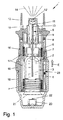
図1及び図2は、流体2、特に、効能の高い薬剤等を噴霧化する公知のネブライザ1を非引張り操作状態(図1)及び引張り操作状態(図2)で概略的に示している。ネブライザ1は、特に、携帯型吸入器として具体化され、好ましくは、推進ガスなしで動作する。
1 and 2 schematically show a
流体2、好ましくは液体、特に薬剤を噴霧化すると、エーロゾルが生じ、かかるエーロゾルは、ユーザ(図示せず)により吸息又は吸入可能である。通常、吸入は、好ましくは定められた時間間隔で1日に少なくとも1回、特に1日に数回行われる。
Nebulization of
ネブライザ1は、流体2を収容すると共に噴霧化されるべき流体2のリザーバを形成する挿入可能な且つ好ましくは交換可能な容器3を有する。好ましくは、容器3は、特に所定の投薬期間、例えば一箇月の間における多数回の塗布又は少なくとも50回、好ましくは少なくとも100回の投与量若しくはスプレーに十分な量の流体2を収容する。
The
容器3は、実質的に円筒形又はカートリッジの形状をしており、ネブライザ1をいったん開けた後、容器をネブライザ内に挿入でき、オプションとして交換できる。この容器は、好ましくは硬質構造のものであり、流体2は、好ましくは、容器3内の袋4内に保持される。
The
ネブライザ1は、特に所定の、オプションとして調節可能な投与量で流体2を運搬すると共にこれを噴霧化するための圧力発生器5を有する。圧力発生器5は、容器3のためのホルダ6及び関連の駆動ばね7(一部しか示していない)を有し、この駆動ばねは、これを解除するよう手動操作可能な制止要素8を有し、圧力発生器5は、逆止弁10を備えた運搬管9、圧力チャンバ11及びマウスピース13の付近に設けられた噴出ノズル12を更に有している。
The
駆動ばね7を軸方向に引っ張っている間、ホルダ6は、容器3及び運搬管9と共に図面において下方に移動し、流体2は、容器3から吸い出され、逆止弁10を通って圧力発生器5の圧力チャンバ11内に吸い込まれる。噴出ノズル12は、非常に小さな流れ断面を有していて特に毛管として具体化されているので、スロットル効果が生じ、かかるスロットル効果は、逆止弁が設けられていない場合であってもこの時点では空気が吸い込まれるのを確実に阻止するに足るほど強力である。
While pulling the
ロック要素8の作動後における次の弛緩中、圧力チャンバ11内の流体2は、駆動ばね7が運搬管9を上方に戻すことによって、即ち、ばね力によって圧力下に置かれ、そして噴出ノズル12を通って放出され、ここで噴霧化されて特にμm又はnm範囲の粒子になり、好ましくは図1に示されているようにエーロゾル14のクラウド(雲)又はジェットを形成する約5μmの肺行きの粒子になる。かくして、流体2の運搬及び噴霧化は、純粋に機械的に、即ち、推進ガスなしで且つ電気手段なしで実施される。
During the next relaxation after the actuation of the locking element 8, the
ユーザ(図示せず)は、エーロゾル14を吸入することができ、その間、供給空気を少なくとも1つの給気開口部15を通ってマウスピース13内に吸い込むことができる。
A user (not shown) can inhale the
ネブライザ1は、上側ハウジング部品16及びこれに対して回転可能な内側部品17を有し、特に手動操作可能なハウジング部品18が好ましくは保持要素19によって内側部品17に解除可能に固定され、特に嵌められている。容器3を挿入したり且つ/或いは交換したりするために、ハウジング部品18をネブライザ1から取り外すことができる。
The
ハウジング部品18を手動で回転させることにより、内側部品17を上側ハウジング部品16に対して回転させることができ、それにより、駆動ばね7をホルダ6に作用する歯車(図示せず)により軸方向に引っ張ることができる。引っ張り操作中、容器3は、軸方向下方に動かされ、ついには、容器3が引っ張り操作状態にある図2に示されている端位置を占めるようになる。噴霧化プロセス中、容器3は、駆動ばね7によってその元の位置に戻される。
By manually rotating the
ハウジング部分18は好ましくは、キャップ状の下側ハウジング部品を形成し、容器3の下方自由端部周りに又はこの上に嵌まっており、下側ハウジング部品により容器3を挿入方向Eにおいて上側ハウジング部品16上に又は上側ハウジング部品16内に押してこれに取り付けることができる。駆動ばね7を引っ張ると、容器3は、その端部分と共にハウジング部品18内へ(更に)動き又はその端フェースに向かって動き、他方、ハウジング部品18内に設けられた軸方向に作用するばね20が、容器のベース(底)21に当接し、容器が最初に穿通要素19に接触すると、このばねは、穿通要素22により容器3又はこれに設けられたベースシールを穿通し、空気を取り込むことができる。
The
ネブライザ1は、好ましくはハウジングの上側部品16に対する内側部品17の回転を検出することにより、ネブライザ1の作動回数をカウントするモニタ装置23を有している。モニタ装置23は、図示の実施形態では純粋に機械的に動作する。
The
提案対象のネブライザ1及び提案対象のハウジング状コンポーネント18の構成及び動作モードについて以下に詳細に説明する。図3〜図6を参照する。しかしながら、図1及び図2に示された公知のネブライザ1との本質的な違いについてのみ強調する。かくして、図1及び図2に関連した注意事項は、そのまま当てはまり又は補完的に当てはまる。
The configurations and operation modes of the proposed
今、まず最初に、図3〜図5を参照する。 Reference is first made to FIGS.
これらの図は、提案対象ネブライザ1の第1の実施形態を示している。
These figures show a first embodiment of the proposed
ネブライザ1は、上側ハウジング部品16及び上側ハウジング部品16に解除可能に連結されるのが良い下側ハウジング部品18を有している。
The
特定の有効物質の入った容器3が既に下側ハウジング部品18内に固定的に取り付けられ又はこれから分離できないようになっており、その結果、下側ハウジング部品18は、容器3付きの小売りユニットを形成している。
The
下側ハウジング部品18は、モニタ装置23を備えている。
The
下側ハウジング部品18は、1つ又は好ましくは2つのコード付け手段26を収容しており、好ましくは、各コード付け手段は、自由に通過可能な溝260及び自由には通過可能ではない複数本の溝261を有している。
The
以下においてコード付け手段26の形態及び機能について詳細に説明する。 Hereinafter, the form and function of the coding means 26 will be described in detail.
上側ハウジング部品16は、クロージャ部材24に連結された1つ又は好ましくは2つの同一構造のコード付け手段25を有している。
The
さらに、コード付け手段25のピン状突出部250及び半径方向に突き出たノーズ251が示されている。
Furthermore, a pin-
クロージャ部材24は、ラッチ止め要素240によって内側部品17のラッチ止め開口部170内に保持されている。
The
ロック及びロック解除要素242がクロージャ部材24に一体的に連結されている。
A locking and unlocking
ロック及びロック解除要素242を半径方向に押し込むことができ、かかるロック及びロック解除要素は、解除可能な下側ハウジング部品18をロックし又はロック解除したりするのに役立つ。
The locking and unlocking
図5は、コード付け手段26の外壁が下側ハウジング部品18の内壁に当接した状態を示している。以下に詳細に説明するように、コード付け手段26は、上側ハウジング部品16に取り付けられたコード付け手段25と協働する。
FIG. 5 shows a state in which the outer wall of the coding means 26 is in contact with the inner wall of the
容器3は、ベース要素28によって下側ハウジング部品18に固定的に取り付けられている。具体的に説明すると、ベース部材28は、数個の、好ましくは4個のばね状アームから成り、これらばね状アームは、これらの端部が容器3の幅が広くなったベース領域上に延びている。
The
次に、図6〜図8を参照してコード付け手段25,26の形状及び協働状態について説明する。 Next, the shape and cooperating state of the coding means 25 and 26 will be described with reference to FIGS.
コード付け手段26の各々は、仮想の中空筒体H(図7の湾曲した曲線を比較参照されたい)の壁の一部のように構成されている。コード付け手段26の壁は、それぞれ仮想の中空筒体Hの対称軸線Sに延びた4本の溝261,260を有している。
Each of the coding means 26 is configured as part of the wall of a virtual hollow cylinder H (see the curved curve in FIG. 7 for comparison). The wall of the coding means 26 has four
溝260は、自由に通過可能な溝として具体化され、溝261は、少なくとも一端に横方向壁262を有し、この横方向壁は、自由通過を制止する。
The
図8は、上側ハウジング部品16に連結されたコード付け手段25の詳細図である。
FIG. 8 is a detailed view of the coding means 25 connected to the
コード付け手段25は、同一構造のものであり、形状が環状である。 The coding means 25 has the same structure and has a ring shape.
環状コード付け手段25は、一方の端フェースに開口部252を備え且つ反対側にピン状突出部250を備えている。開口部252は、これらがピン状突出部250を受け入れることができるよう構成され、その結果、コード付け手段25は、これらの端フェースが互いに当接した状態で位置することができるようになっている(図4及び図5も又比較参照されたい)。
The annular coding means 25 has an
加うるに、各コード付け手段25は、その半径方向外側にノーズ251を有している。
In addition, each coding means 25 has a
開口部252及び更にピン状突出部250は、環状コード付け手段25の周囲全体にわたって等距離を置いて分布された状態で配置されていることは明らかである。好ましくは、12個の開口部252が一方の端フェースに設けられ、6本のピン状突出部250が反対側の端フェースに設けられている。かくして、コード付け手段25及びそれ故にノーズ251を複数の角度位置で互いに対して整列させることができる。
Obviously, the
ノーズ251は、このノーズが動くことができるが安全に案内されるようにこのノーズをコード付け手段26の自由に通過可能な溝260内に受け入れることができるよう構成されている。
The
製造プロセスの際、所望のコード付けに応じて、2つのコード付け手段25の端フェースを互いに合わせ、次に上側ハウジング部品16に、特に内側部品17に取り付けられたクロージャ部材24に取り付ける。
During the manufacturing process, depending on the desired coding, the end faces of the two coding means 25 are brought together and then attached to the
端フェースに設けられたクロージャ部材24のピン状突出部241は、上記のように配置されたコード付け手段25の開口部252内に嵌まり込む(図5を比較参照されたい)。
The pin-
コード付け手段26は、詳細には図示していない仕方で下側ハウジング部品18の内壁にラッチ止めされている。
The coding means 26 is latched to the inner wall of the
言及すべきこととして、コード付けの前に、コード付け要素26は、溝260,261の全てが横方向壁262(図6では頂部に配置され、下の方に破線で示されている)を備えるよう構成されている。横方向壁262は各々、好ましくは、一種の脆弱な箇所の形態をしている。
It should be noted that prior to coding, the
最終のコード付けのため、各コード付け手段26は、自由に通過可能な溝を備えることが必要である(図示の実施形態では溝260)。これは、溝の横方向壁262の両方を除去することによって行われる。他の溝261の横方向壁は、明確なコード付けを提供するためにコード付け手段26の組み立て位置において上側ハウジング部品16(即ち、図6の場合では頂部のところ)と整列しなければならない少なくとも1つの横方向壁262を保持しなければならない。
For final coding, each coding means 26 should be provided with a freely passable groove (groove 260 in the illustrated embodiment). This is done by removing both of the
両方の横方向壁262が自由には通過できない溝261内の定位置に残されている場合(図6の実施形態とは対照的に)、これは又、コード付け手段26にそれ以上の改造を加えないで180°旋回させることによって、自由に通過可能な溝260がこの場合異なる場所に位置することになるので異なる場所に位置することになるので異なるコード付けを達成することができるという利点を有する。
If both
理解されるように、2つのコード付け手段26とこれらの4つのそれぞれのコード付けオプション(溝)及び2つの環状コード付け手段25を組み合わせることによって、全部で16個の考えられるコードを得ることができる。したがって、これにより、コードの融通性が提供される。 As can be seen, by combining the two coding means 26 with these four respective coding options (grooves) and the two annular coding means 25, a total of 16 possible codes can be obtained. it can. This therefore provides code flexibility.
次に、図9〜図12を参照して提案対象のネブライザ1の第2の実施形態について説明する。
Next, a second embodiment of the proposed
各々、仮想の中空筒体の壁の一部のように構成された少なくとも1つ又は2つの壁を含むコード付け手段27(図6のコード付け手段26に対応する)が解除可能な下側ハウジング部品18内に挿入されている。
Lower housing with releasable coding means 27 (corresponding to coding means 26 in FIG. 6) each including at least one or two walls configured as part of a wall of a virtual hollow cylinder It is inserted into the
この実施形態では、下側ハウジング部品18は又、好ましくは小売りユニットとして容器3に分離不能に又は既に固定的に連結されており、好ましくは、容器3は、加うるに、環状支持要素29によって半径方向に支持されている。
In this embodiment, the
コード付け手段27の壁は、好ましくは、約180°だけ互いにオフセットしており、壁は各々、容器3の挿入方向に延びる少なくとも1本の溝270を有している。
The walls of the coding means 27 are preferably offset from each other by about 180 °, each wall having at least one
これらの壁は、特に図11から明らかなように互いに一体的に連結されている。 These walls are integrally connected to each other, as is apparent from FIG.
この図は又、ベース要素28を明確に示しており、ベース要素28は、半径方向内方に曲げられたアーム281によって容器3をそのベースのところで取り付けるのに役立つ。
This figure also clearly shows the
半径方向外方に曲げられたアーム280がコード付け手段27のベース領域の背後に係合し、そしてコード付け手段27を下側ハウジング部品18内にしっかりと保持し、その結果、コード付け手段が失われることがないようになっている。図示の実施形態では、溝270も又、約180°だけ互いにオフセットしている。
A radially outwardly
特に図10から理解できるように、コード付け手段27の2つの壁は、下方領域に細長い溝状凹み271を備えている。好ましくは、7つのかかる凹み271が設けられている。
As can be seen in particular from FIG. 10, the two walls of the coding means 27 are provided with elongated groove-
これとは対照的に、下側ハウジング部品18は、その内壁に凹み271の付近でその内壁に少なくとも1つの細長い膨らみ(詳細には示されていない)を有し、この膨らみは、細長い凹み271のうちの少なくとも1つに対応するのがよい。
In contrast, the
明らかなこととして、凹みを下側ハウジング部品18に設けると共に膨らみをコード付け手段27の壁に設けることも又可能である。
Obviously, it is also possible to provide a recess in the
容易に理解されるように、コード付け手段27は、かくして、7つの考えられる明確に規定された位置を占めることができる。 As will be readily appreciated, the coding means 27 can thus occupy seven possible clearly defined positions.
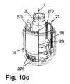
図10a〜図10cは、製造プロセス中に下側ハウジング部品18の最終のコード付けを固定することがいかに容易であるかを示している。
FIGS. 10a to 10c show how easy it is to secure the final coding of the
かくして、下側ハウジング部品18は、図10aではコード付けがなされていない状態にある。コード付け手段27は、コード付け手段27の細長い凹み271が下側ハウジング部品18の細長い膨らみと係合関係をなさない程度まで下側ハウジング部品18から突き出ている。
Thus, the
したがって、コード付け手段27は、容器3又は下側ハウジング部品18の長手方向軸線Lを中心として特定の角度範囲にわたって自由に回転できる。
Thus, the coding means 27 is free to rotate over a specific angular range about the longitudinal axis L of the
提供される7つの細長い膨らみ271に従って、これら7つの考えられる位置のうちの1つは、かくして、自由回転によって選択できる。
According to the seven
図10aでは、左側への回転によって考えられる位置が選択されており、次に、最終の固定又はコード付けが細長い凹み271と下側ハウジング部品18の細長い膨らみの協働によって(図10c)コード付け手段27を下側ハウジング部品18内に押し込み又は圧入することによって得られている。
In FIG. 10a, a possible position is selected by rotation to the left, and then the final fixation or coding is performed by the cooperation of the
図12a〜図12cは、一例としてこの実施形態に対応した上側ハウジング部品16を示している。
12a to 12c show an
上側ハウジング部品16は、スリーブ状コード付け手段30を備えている。
The
スリーブ状コード付け手段30は、上側ハウジング部品16の内側部品17に押し嵌めされている。
The sleeve-like coding means 30 is press fitted onto the
上述したように下側ハウジング部品18のコード付けに従って、上側ハウジング部品16についても製造プロセスにおいて最終のコード付けも又非常に後で作ることができる。
According to the coding of the
かくして、図12aは、コード付け手段30を中立の位置で示しており、この中立位置では、コード付け手段30は、まだコード付けされておらず、特に、その長手方向軸線Lを中心として或る特定の角度範囲にわたり内側部品17に対して依然として自由に回転可能である。
Thus, FIG. 12a shows the coding means 30 in a neutral position, in which the coding means 30 has not yet been coded, in particular with its longitudinal axis L as the center. It is still freely rotatable with respect to the
かくして、具体的に言えば、ロック及びロック解除要素242と内側部品17との間には間隙が形成され、その結果、コード付け30の回転が阻害されることがないようになっている。
Thus, specifically, a gap is formed between the locking and unlocking
コード付け手段は、好ましくは180°オフセットした2つのリブ状突出部301を更に有し、これらリブ状突出部は、上側ハウジング部品18のコード付け手段27の溝270に嵌まり込むように形作られている。
The coding means further comprises two rib-
好ましくは、周囲に沿って4つの箇所のところに均等に分布して設けられたコード付け手段30も又、7つの細長い凹部300を備えている。凹部300は、内側部品17に設けられた対応の細長い突出部171と協働するよう具体化されており、細長い突出部171は、好ましくは周囲に沿って90°だけオフセットした状態で内側部品17に配置されている。
Preferably, the coding means 30 provided evenly distributed at four locations along the circumference also comprises seven
図12bでは、コード付け手段30は、その中立位置から可能な最終位置まで右側に回されており、次に、図12cでは、内側部品上に更に押されており、その結果、細長い凹部300のうちの1つが細長い突出部171のうちの1つと協働することができ、かくして上側ハウジング部品16のコード付けも又固定することができるようになっている。
In FIG. 12 b, the coding means 30 has been turned to the right from its neutral position to the final position possible, and then in FIG. 12 c it has been pushed further onto the inner part, so that the
かくして、考えられる7つのコードを同一のコンポーネントの使用により容易に作ることができる。 Thus, seven possible codes can be easily created by using the same components.
図13〜図16を参照して提案対象のネブライザ1の第3の実施形態について説明する。
A third embodiment of the proposed
ネブライザ1のコード付けは、この実施形態では、2つの環状コード付け要素31,32しか有していない。
The coding of the
図14では、環状コード付け要素31,32が詳細に記載されている。
In FIG. 14, the
明らかなように、コード付け要素31,32は各々、実質的にL字形の断面を有し、コード付け要素31は、好ましくは、端フェースに12個の貫通開口部310を有し(即ち、Lの腕の水平領域に配置されている)、これら貫通開口部は、周囲に沿って等距離を置いて分布して設けられている。
As can be seen, the
同様に、コード付け要素32は、好ましくは、その端フェースに周囲に沿ってぐるりと等距離を置いて分布した状態で設けられた12個の貫通開口部320を有している。
Similarly, the
コードに合致するため、コード付け手段32は、上側ハウジング部品16又は内側部品17に向かう容器3の挿入方向E(図15参照)に延びる長方形の突出部321を備えている。
In order to match the code, the coding means 32 comprises a
対応の仕方で、コード付け手段31は、長方形の凹部311を備え、この凹部311は、これが突出部321と嵌合方式で協働することができるよう形作られている。
In a corresponding manner, the coding means 31 comprises a
図15及び図16は、特に、コード付け手段31が上側ハウジング部品16に連結され、コード付け手段32が下側ハウジング部品18に連結されている状態を示している。
FIGS. 15 and 16 show in particular the state in which the coding means 31 are connected to the
具体的に説明すると、コード付け手段31をその貫通開口部310が選択位置にある状態でクロージャ部材24のピン状突出部241に押し付け(図5の上側リング25と同等な仕方で)、クロージャ部材24は、上側ハウジング部品16の内側部品17に取り付けられている。
Specifically, the cording means 31 is pressed against the pin-
かくして、コード付け手段31は、規定された位置に固定されている。 Thus, the coding means 31 is fixed at a prescribed position.
コード付け手段32を貫通開口部320のところで下側ハウジング部品18のピン状突出部181に押し付け、かくして、これ又規定された位置に保持する。
The coding means 32 is pressed against the pin-
長方形の突出部321は、その上端部のところに、半径方向外方に差し向けられたノーズ322を更に備え、このノーズは、コード付け手段32の組み立て位置では、下側ハウジング部品18の半径方向に包囲した溝180の後に係合する。
The
かくして、突出部321は、半径方向内方にシフトして下側ハウジング部品18及び上側ハウジング部品16のコードが互いに合致したときに下側ハウジング部品18と上側ハウジング部品16が互いに接合されるのを阻止することができない状態で、下側ハウジング部品18内にしっかりと保持される。
Thus, the
これらコードが合致しない場合、即ち、一方において下側ハウジング部品18の突出部321と他方において上側ハウジング部品16の凹部311が各々異なる角度位置にある場合、ハウジング部品16,18を互いに完全に嵌め合うことが可能ではない。
If these codes do not match, i.e., if the
特に、突出部321は、上側ハウジング部品16内に入っている運搬管9が容器3内に十分遠くまで通過して容器3内に入っている有効物質で運搬管9を汚染することができないような高さhを有している。
In particular, the
この領域では環状であるクロージャ部材24のピン状突出部241と下側ハウジング部品18のピン状突出部181の両方は、貫通開口部310,320と同様な仕方で周囲に沿って等距離を置いて分布して設けられている。かくして、コード付け手段31,32を上側ハウジング部品16及び下側ハウジング部品18内の多くの互いに異なる位置に規定された仕方で設けることができる。
Both the pin-
以下、図17〜図25を参照して本発明のネブライザ1の第4の実施形態について説明する。主として、以下において、一般的な注意事項及び他の実施形態に関する注意事項が好ましくは追加的に又は同様な仕方で当てはまるよう本質的な違いについて説明する。特に、第4の実施形態は、第2の実施形態に比較的類似しており、従って、それぞれの注意事項、特徴及び観点は、同様な仕方で又は追加的に当てはまると言える。
Hereinafter, a fourth embodiment of the
図17は、ハウジング部品18が取り外された状態でネブライザ1を斜視図で示している。容器3は、好ましくは、ハウジング部品18から分離できない。
FIG. 17 shows the
ハウジング部品18は、好ましくは、ネブライザ1の外側ハウジングの一部をなしている。
The
コード付け手段30がネブライザ1、特にネブライザ1の上側部品16又は内側部品17と関連している。このコード付け手段30は、以下において第1のコード付け手段とも呼ばれる。
A coding means 30 is associated with the
別のコード付け手段27が下側ハウジング部品18及びかくして容器3及び/又は容器3内に入っている流体2(図示せず)のためのコード又はコード付けを提供するために下側ハウジング部品18と関連している。このコード付け手段27は又、以下において第2のコード付け手段とも呼ばれ、その目的は、互いに異なるコード付け手段の区別を容易にすることにある。
Another coding means 27 provides the
一般に、コード付け手段27,30は、コード付け手段27,30が合致したコード又はコード付けを有した場合にのみ容器3をネブライザ1中に挿入する(完全に挿入する)しかできず或いはこれと流体連結するしかできず又はこれと共に使用することしかできないよう互いに協働するよう構成されている。換言すると、合致していないコード付けを備えた容器3又は下側ハウジング18を使用することができない。かくして、コード又はコード付けは、特に、互いに異なる容器3又は好ましくは互いに異なるコード付けを備えた互いに異なるハウジング部品18の中から選択するよう用いられる。
In general, the coding means 27, 30 can only (or fully) insert the
特に、ハウジング部品18は、両方のコード付け27,30のコード付けが合致した場合にのみネブライザ1、特にその上側ハウジング部品16又は内側部品17に取り付けられ(完全に取り付けられ)又は押し嵌めされ(完全に押し嵌めされ)るのが良い。
In particular, the
図18は、ハウジング部品18が下から見て斜視図の状態で第4の実施形態としてのネブライザ1を示している。
FIG. 18 shows the
第1のコード付け手段30は、互いに異なる位置で、特に互いに異なる回転位置で、ネブライザ1、特にネブライザ1の内側部品17又はネブライザ1の任意他の部品(下側ハウジング部品18を除く)に取り付け可能である。
The first coding means 30 are attached to the
互いに異なる位置及びかくしてコード付けは、好ましくは、マーキング33、特に、この実施形態では数字又は任意他の記号等で指示される。
The different positions and thus the coding is preferably indicated by
この実施形態では、多数の又は3つ以上又は4つ以上の位置、好ましくは7つの互いに異なる位置の採用が可能である。 In this embodiment, it is possible to employ multiple or more than two or more than four positions, preferably seven different positions.
図19は、第2のコード付け手段27が斜視図の状態で下側ハウジング部品18を示している。
FIG. 19 shows the
第2のコード付け手段27は、上述の実施形態のうちの1つに関連して説明したように、特に、第1又は第2の実施形態に関して説明したように形成され又は実現されるのがよい。 The second coding means 27 may be formed or implemented as described in connection with one of the above embodiments, in particular as described with respect to the first or second embodiment. Good.
好ましくは、第2のコード付け手段27は、少なくとも1つの自由に通過可能な溝270を含む。さらに、第2のコード付け手段27は、多数本の自由には通過できない溝271を有するのがよく、この場合、これらの溝271のうちの少なくとも1本は、自由に通過可能な溝270を形成するため、かくして第2のコード付け手段27を所望通りにコード付けするために自由に通過可能に(特に、横方向壁等を除去することによって)作られるのがよい。例えば、1本以上又は2本以上或いはそれ以上の溝270は、特にハウジング部品18のコード付けが第1のコード付け手段30のコード付け又はネブライザ1と合致するようコード付けを所望通りに設定するために自由に通過可能に作られるのがよい。
Preferably, the second coding means 27 includes at least one freely
第2のコード付け手段27は、1つ又は2つ以上のインサート、コード付け要素等によって形成されるのがよい。変形例として、第2のコード付け手段27は、ハウジング部品18又は容器3と関連した任意他のコンポーネント又は容器3内に形成され或いはこれによって形成されたそれぞれの凹部、溝270等によって形成されてもよい。
The second coding means 27 may be formed by one or more inserts, coding elements or the like. As a variant, the second coding means 27 is formed in the
さらに、第2のコード付け手段27、即ち、容器3及び/又はハウジング部品18と関連したコード付け手段を互いに異なる規定の位置に設けることができず又はコード付けに関して設定することができない。これとは異なり、コード付けをあらかじめ定めることができ又は固定することができる。この場合、好ましくは、互いに異なる第2のコード付け手段27を備えた互いに異なるハウジング部品18が互いに異なるコード付けのために用いられる。特に、互いに異なるハウジング部品18は、第2のコード付け手段27及び/又は自由に通過可能な溝270の円周方向配置場所に関して互いに異なっている。
Furthermore, the second coding means 27, i.e. the coding means associated with the
図20〜図23は、各ハウジング部品18が規定のコード付けを1つしか有していない、特に、関連の第2のコード付け手段27が互いに異なる規定の位置に取り付けることができず且つ/或いはコード付けを例えば横方向壁等を除去することによって改造することができない変形例を示している。
20 to 23 show that each
この実施形態では、多数の又は7つの互いに異なるハウジング部品18がネブライザ1、内側部品17及び/又は第2のコード付け手段30について可能な多数の又は7つの互いに異なるコード付けに対応した多数の又は7つの互いに異なるコード付けを実現するために使用できる。
In this embodiment, multiple or seven
とりわけ図20に示されているように、第1のコード付け手段30は、好ましくは、半径方向に且つ/或いは外方に延びる好ましくは少なくとも1つ、この場合2つの突出部301を含む。これら突出部301は、第1及び第2のコード付け手段30,27のコード付けが合致した場合にハウジング部品18をネブライザ1又は内側部品17に取り付けたときに対応の且つ/或いは自由に通過可能な溝270と相互作用することができ又はこの中に動くことができる。
In particular, as shown in FIG. 20, the first coding means 30 preferably comprises at least one, in this case two
図21は、図20の左側の円で囲んだ部分の部分拡大図の状態で、突出部301をハウジング部品18のところで又はハウジング部品18内に且つ/或いはハウジング部品18によって形成された対応の溝270内に動かされる直前の状況を示している。図22は、図20の右側の円で囲んだ部分の同様な拡大図の状態で、第2の突出部に関して同様な状況を示している。
FIG. 21 is a partially enlarged view of the left circled portion of FIG. 20 with the
好ましくは、突出部301は、互いに異なる、互いに逆の且つ/或いは円周方向をオフセットした方向に突き出る。
Preferably, the
図23は、ハウジング部品18が閉鎖され(完全に閉鎖され)又は取り付けられ(完全に取り付けられ)た状態(容器3は設けられていない)でのネブライザ1の概略断面図を示している。図23は、特に、第2のコード付け手段27中への第1のコード付け手段30の嵌入又は溝270中へのそれぞれの少なくとも1つの突出部301の嵌入状態を示している。
FIG. 23 shows a schematic cross-sectional view of the
「自由に通過可能」という表現は、特に、それぞれの突出部309が溝270内に軸方向に動くことができ又はこの溝270を通過してネブライザ1を完全に閉鎖することができ、即ち、ハウジング部品18をネブライザ1又はその内側部品17に完全に取り付け又は押し嵌めすることができることを意味している。
The expression “freely passable” means in particular that each protrusion 309 can move axially into the
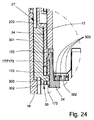
図24は、図23の円で囲んだ部分の部分拡大図である。図25は、ハウジング部品18が省かれ、コード付け手段30が取り外された状態のネブライザ1を示している。
24 is a partially enlarged view of a portion surrounded by a circle in FIG. FIG. 25 shows the
コード付け手段30は、好ましくは、ネブライザ1、特に内側部品17又はネブライザ1の任意他のコンポーネント若しくは上側ハウジング部品16に取り付けられ又は取り付け可能な別個の部品によって形成される。
The coding means 30 is preferably formed by a separate part attached to or attachable to the
コード付け手段30は、好ましくは、リング状であり又は好ましくはリング状部分302を有している。
The coding means 30 is preferably ring-shaped or preferably has a ring-shaped
特に、コード付け手段30は、好ましくはリング状又はスリーブ状連結部分302を有している。この連結又はリング部分302は、好ましくは、少なくとも1つの突出部301を保持している。
In particular, the coding means 30 preferably has a ring-like or sleeve-like connecting
好ましくは、突出部301は、連結又はリング部分302上に且つ/或いは内側部品17及び/又は内側部品17の周りに若しくは内側部品17に設けられたオプションとしてのカバーリング34上に軸方向に突き出ている。好ましくは、連結又はリング部分302は、第1のコード付け手段30がネブライザ1又は内側部品17に取り付けられると、カバーリング34に軸方向に隣接して位置する。
Preferably, the
この実施形態では、マーキング33は、好ましくは、カバーリング34のところの又はカバーリング34上に配置されている。
In this embodiment, the marking 33 is preferably located at or on the
コード付け手段30は、好ましくは、スナップ嵌め及び/又は圧力嵌めによってネブライザ1又は内側部品17に取り付けられ又は固定される。
The coding means 30 is preferably attached or fixed to the
この実施形態では、コード付け手段30又は連結/リング部分302は、好ましくは、ネブライザ1、カバーリング34又は内側部品17、特にこれらに形成された対応の係合手段、例えば特に図25に示されているように1つ又は2つ以上の係合凹部172等と嵌合する係合手段、特に1つ又は2つ以上の歯303を有する。
In this embodiment, the coding means 30 or the coupling /
好ましくは、歯303は、内方に突き出ると共に/或いは連結又はリング部分302のところに配置される。
Preferably, the
好ましくは、内側部品17は、1つ又は2つ以上の歯303の係合によってコード付け手段30を保持する1つ又は2つ以上の係合凹部172を備えた1つ又は2つ以上の軸方向に延びる舌部173を有している。
Preferably, the
好ましくは、コード付け手段30を最終の部品として、即ち、他の全ての部品を取り付けた後に、ネブライザ1に取り付けるのがよい。
Preferably, the coding means 30 is attached to the
好ましくは、コード付け手段30は、所望のコード付けに応じて、好ましくはマーキング33を考慮してネブライザ1又はその内側部品17と回転的に整列し、次に、内側部品17上に軸方向に押し嵌めされ、かくして、好ましくは解除できないように、ネブライザ1/内側部品17のところに固定され又はスナップ装着される。
Preferably, the coding means 30 is rotationally aligned with the
コード付け手段30の回転位置決め又はその回転位置の指示を容易にするため、1つの突出部301又はコード付け手段30のオプションとしての箇所若しくは目印304がそれぞれのマーキング33に向くのがよい。この実施形態では、1つ又は2つ以上の目印304が図25に示されているように突出部301の側に形成されている。
In order to facilitate the rotational positioning of the coding means 30 or the indication of the rotational position, one
一般に、ハウジング部品18は、好ましくは、保持要素19を受け入れる非円形の且つ/或いは受け入れ部分35を有すると共に/或いは好ましくは特にハウジング部品18が一般に1つの規定された回転位置でのみネブライザ1又はその内側部品17に連結可能であり又は取り付け可能であるように係合部分36を有する。コード付け手段27又は少なくとも1つの好ましくは自由に通過可能な溝270は、ハウジング部品18の追加の要素又は特徴部であり、そして、コード付けに応じて互いに異なる回転位置に配置される。かくして、コード付けにより、互いに異なるコード付けを備えた互いに類似したハウジング部品18相互間の選択が可能である。
In general, the
上述した実施形態、特に、かかる実施形態の個々の要素及び観点は、必要に応じて互いに組み合わせ可能であると共に/或いはこれらの運動学的動作において逆にすることができる。特に、コード付け手段の規定された選択可能な位置の数及び配置は、必要に応じて変更可能であると共に特定の条件に適合可能である。 The embodiments described above, in particular the individual elements and aspects of such embodiments, can be combined with one another as needed and / or can be reversed in their kinematic behavior. In particular, the number and arrangement of defined selectable positions of the coding means can be varied as required and adapted to specific conditions.
1 ネブライザ
2 流体
3 容器
4 袋
5 圧力発生器
6 ホルダ
7 駆動ばね
8 制止要素
9 運搬管
10 逆止弁
11 圧力チャンバ
12 噴出ノズル
13 マウスピース
14 エーロゾル
15 給気開口部
16 上側ハウジング部品
17 内側部品
170 ラッチ止め開口部
171 細長い突出部
172 係合凹部
173 舌部
18 解除可能なハウジング部品(下側部品)
180 包囲溝
181 ピン状突出部
19 保持要素
20 ばね(下側ハウジング部品内に設けられている)
21 容器ベース
22 穿刺要素
23 モニタ装置
24 固定のためのラッチ止め要素を備えたクロージャ部材
240 ラッチ止め要素
241 ピン状突出部
242 ロック/ロック解除要素
25 環状コード付け手段
250 ピン状突出部
251 ノーズ
252 開口部
26 取り外し可能なハウジング部品内に設けられたコード付け手段
260 自由に通過できる溝(自由通過溝)
261 自由には通過できない溝(非自由通過溝)
262 横方向壁
27 取り外し可能なハウジング部品内に設けられたコード付け手段
270 溝
271 細長い凹み
28 ベース要素
280 外方に曲げられたアーム
281 内方に曲げられたアーム
29 環状支持要素
30 スリーブ状コード付け手段
300 細長い凹部
301 リブ状突出部
302 連結又はリング部分
303 歯
304 目印
31 環状コード付け手段
310 貫通開口部
311長方形凹部
32 環状コード付け手段
320 貫通開口部
321 長方形突出部
322 ノーズ
33 マーキング
34 カバーリング
35 受け入れ部分
36 係合部分
E 上側又は下側ハウジング部品中への容器の挿入又は導入方向
h 突出部の高さ
H 中空筒体
L 長手方向軸線
S 中空筒体の対称軸線
DESCRIPTION OF
180
DESCRIPTION OF
261 Grooves that cannot pass freely (non-free passage grooves)
262
Claims (27)
少なくとも前記ネブライザ(1)に関連した前記コード付け手段(25;30;31)は、前記ネブライザ(1)に又は前記ネブライザ(1)の部材に、選択可能に規定された異なる複数の位置の一つで、固定的に取り付け可能な、別個の部品であり、前記コード付け手段(25,26;27,30;31,32)が互いに合致する各位置で異なるコード付けが得られる、又は各位置で異なるコード付けを得ることにより前記ネブライザ(1)の前記コード付けが設定され、前記ネブライザ(1)は、前記コード付け手段(25;30;31)で選択可能に異なるコード付けに適合することが可能である、ネブライザ。 A nebulizer (1) for a fluid (2), wherein a container (3) containing the fluid (2) can be inserted into the nebulizer, the nebulizer carrying the fluid (2) And / or atomizing pressure generator (5), provided with coding means (25, 26; 27, 30; 31, 32), said coding means being said coding means (25, 26) 27, 30; 31, 32) each other so that the container (3) can be inserted into the nebulizer (1) or used with the nebulizer (1) only if it has a matching cord. In collaboration with the nebulizer,
At least the coding means (25; 30; 31) associated with the nebulizer (1) is provided at one of a plurality of differently defined positions on the nebulizer (1) or on a member of the nebulizer (1). In other words, it is a separate part that can be fixedly attached and a different coding is obtained at each position where the coding means (25, 26; 27, 30; 31, 32) match each other, or each position The coding of the nebulizer (1) is set by obtaining a different coding in, and the nebulizer (1) is adapted to a different coding which is selectable by the coding means (25; 30; 31) Is possible, nebulizer.
前記コード付け手段(26;27;32)は、別個の部品であり、前記コード付け手段(26;27;32)は、選択可能に規定された異なる複数の位置の一つで前記ハウジング状コンポーネント(18)上に又は前記ハウジング状コンポーネント(18)内に取り付けられ又は交換可能であるよう構成され、前記ハウジング状コンポーネント(18)は、前記コード付け手段(26;27;32)で選択可能に異なるコード付けに適合することが可能である、ハウジング状コンポーネント。 A housing-like component (18) that can be used as a component of a nebulizer (1), a container (3) attachable to the housing-like component (18), a fluid (2) contained in the container (3), Having at least one coding means (26; 27; 32) clearly identifying the active substance concentration of the fluid (2) and / or the amount of the fluid (2) added to the container (3); The coding means (26; 27; 32) cooperates with another coding means (25; 30; 31) provided in the nebulizer (1) to cooperate with the coding means (26; 27; 32). ) And the other coding means (25; 30; 31) can only be inserted into the nebulizer (1) or the nebulizer (3) To be able to be used with Isa (1), in a housing-like component (18),
Said coding means (26; 27; 32) are separate parts, said coding means (26; 27; 32) being one of a plurality of selectably defined different positions in said housing-like component (18) configured to be mounted or replaceable on or in the housing-like component (18), the housing-like component (18) being selectable by the coding means (26; 27; 32) A housing-like component that can be adapted to different coding.
Applications Claiming Priority (3)
| Application Number | Priority Date | Filing Date | Title |
|---|---|---|---|
| EP12164050.2 | 2012-04-13 | ||
| EP12164050 | 2012-04-13 | ||
| PCT/EP2013/001068 WO2013152861A1 (en) | 2012-04-13 | 2013-04-12 | Nebuliser with coding means |
Publications (2)
| Publication Number | Publication Date |
|---|---|
| JP2015513982A JP2015513982A (en) | 2015-05-18 |
| JP6399459B2 true JP6399459B2 (en) | 2018-10-03 |
Family
ID=47780078
Family Applications (1)
| Application Number | Title | Priority Date | Filing Date |
|---|---|---|---|
| JP2015504880A Active JP6399459B2 (en) | 2012-04-13 | 2013-04-12 | Nebulizer with coding means |
Country Status (7)
| Country | Link |
|---|---|
| US (2) | US9545487B2 (en) |
| EP (1) | EP2836262B1 (en) |
| JP (1) | JP6399459B2 (en) |
| AR (1) | AR090673A1 (en) |
| TW (1) | TW201404413A (en) |
| UY (1) | UY34740A (en) |
| WO (2) | WO2013152894A1 (en) |
Families Citing this family (19)
| Publication number | Priority date | Publication date | Assignee | Title |
|---|---|---|---|---|
| EP2077132A1 (en) | 2008-01-02 | 2009-07-08 | Boehringer Ingelheim Pharma GmbH & Co. KG | Dispensing device, storage device and method for dispensing a formulation |
| JP5670421B2 (en) | 2009-03-31 | 2015-02-18 | ベーリンガー インゲルハイム インターナショナル ゲゼルシャフト ミット ベシュレンクテル ハフツング | Component surface coating method |
| US9265910B2 (en) | 2009-05-18 | 2016-02-23 | Boehringer Ingelheim International Gmbh | Adapter, inhalation device, and nebulizer |
| US10016568B2 (en) | 2009-11-25 | 2018-07-10 | Boehringer Ingelheim International Gmbh | Nebulizer |
| CN102686260B (en) | 2009-11-25 | 2014-10-01 | 贝林格尔.英格海姆国际有限公司 | Nebulizer |
| WO2011064163A1 (en) | 2009-11-25 | 2011-06-03 | Boehringer Ingelheim International Gmbh | Nebulizer |
| EP2585151B1 (en) | 2010-06-24 | 2018-04-04 | Boehringer Ingelheim International GmbH | Nebulizer |
| WO2012130757A1 (en) | 2011-04-01 | 2012-10-04 | Boehringer Ingelheim International Gmbh | Medical device comprising a container |
| US9827384B2 (en) | 2011-05-23 | 2017-11-28 | Boehringer Ingelheim International Gmbh | Nebulizer |
| WO2013152894A1 (en) | 2012-04-13 | 2013-10-17 | Boehringer Ingelheim International Gmbh | Atomiser with coding means |
| EP3030298B1 (en) | 2013-08-09 | 2017-10-11 | Boehringer Ingelheim International GmbH | Nebulizer |
| EP2835146B1 (en) | 2013-08-09 | 2020-09-30 | Boehringer Ingelheim International GmbH | Nebulizer |
| EP3139982B1 (en) | 2014-05-07 | 2022-02-16 | Boehringer Ingelheim International GmbH | Nebulizer |
| KR102443737B1 (en) | 2014-05-07 | 2022-09-19 | 베링거 인겔하임 인터내셔날 게엠베하 | Container, nebulizer and use |
| DK3139984T3 (en) | 2014-05-07 | 2021-07-19 | Boehringer Ingelheim Int | Atomizer |
| GB201605102D0 (en) | 2016-03-24 | 2016-05-11 | Nicoventures Holdings Ltd | Mechanical connector for electronic vapour provision system |
| CN105831811B (en) * | 2016-05-06 | 2018-12-18 | 卓尔悦欧洲控股有限公司 | Atomising device and electronic cigarette with the atomising device |
| JP6761469B2 (en) * | 2016-06-22 | 2020-09-23 | 富士フイルム株式会社 | Polishing liquid, chemical mechanical polishing method |
| US11000068B2 (en) | 2017-06-20 | 2021-05-11 | Cascadia Technologies, LLC | Aerosol inhalant producing device with measurable dose and/or other features |
Family Cites Families (621)
| Publication number | Priority date | Publication date | Assignee | Title |
|---|---|---|---|---|
| US1828864A (en) | 1923-02-20 | 1931-10-27 | Gilmont Products Corp | Method of filling bicompartment collapsible tubes |
| GB414953A (en) | 1932-12-24 | 1934-08-16 | Josef Schoene | Medical injection syringe |
| US2127401A (en) | 1937-11-15 | 1938-08-16 | Gillican Charles Crum | Method of packaging rosin |
| US2161071A (en) | 1938-05-02 | 1939-06-06 | Zellerbach Paper Company | Method of packing frozen food |
| US2321428A (en) | 1939-04-25 | 1943-06-08 | Ferdinand G Schloz | Nozzle |
| US2329311A (en) | 1940-06-05 | 1943-09-14 | Harry F Waters | Method of producing liquid-containing packages |
| US2362103A (en) | 1941-01-04 | 1944-11-07 | Arthur E Smith | Ampoule |
| US2651303A (en) | 1948-11-13 | 1953-09-08 | Richard S Johnson | Inhaler |
| US2720969A (en) | 1953-12-10 | 1955-10-18 | Becton Dickinson Co | Package and mounting for hypodermic syringe assembly |
| DK83175C (en) | 1955-07-04 | 1957-07-22 | Grosserer Gorm Tage Hansen | Air control systems for greenhouses. |
| US2974880A (en) | 1955-11-15 | 1961-03-14 | Drackett Co | Aerosol spray head |
| US2793776A (en) | 1956-05-23 | 1957-05-28 | Lipari Michael | Container attachment for providing a compartmental dispensing receptacle |
| US3172568A (en) | 1959-03-27 | 1965-03-09 | Modern Lab Inc | Pressurized dispensing device |
| US3032823A (en) | 1960-05-26 | 1962-05-08 | Sherman Plastics Corp | Method of forming plastic articles |
| GB951228A (en) | 1961-09-26 | 1964-03-04 | Ici Ltd | Packaging process |
| FR1314002A (en) | 1961-11-24 | 1963-01-04 | Method and device for dispensing a non-compacted substance | |
| US3299603A (en) | 1962-03-12 | 1967-01-24 | Continental Can Co | Method of filling pouches |
| NL297349A (en) | 1962-08-31 | |||
| US3354883A (en) | 1965-03-08 | 1967-11-28 | Southerland Elizabeth Lee | Disposable syringe having frangible means for mixing plural medicaments |
| US3440144A (en) | 1965-05-21 | 1969-04-22 | Andersen Prod H W | Method and apparatus for checking and testing the effectiveness of sterilization |
| US3348726A (en) | 1965-10-24 | 1967-10-24 | Continental Can Co | Pull tab |
| US3457694A (en) | 1966-08-25 | 1969-07-29 | Hideo Tatibana | Method of and apparatus for fusion sealing the opening of flexible plastic bottle-like containers |
| US3491803A (en) | 1966-10-03 | 1970-01-27 | Haskon Inc | Machine for filling with liquids containers having deformable side walls |
| FR1502925A (en) | 1966-10-12 | 1967-11-24 | Vaporisateurs Marcel Franck | Improvements to piston pumps for dispensing liquids or fluid pastes |
| US3425591A (en) | 1967-04-27 | 1969-02-04 | William A Pugh Sr | Container with tear out closure |
| GB1230472A (en) | 1967-07-10 | 1971-05-05 | ||
| US3590557A (en) | 1968-03-07 | 1971-07-06 | Fr Hesser Maschinenfabrick Ag | Apparatus for closing packaging containers with elastically deformable walls |
| US3580249A (en) | 1968-09-16 | 1971-05-25 | Kentaro Takaoka | Aerosol nebulizers |
| US3674028A (en) | 1969-06-04 | 1972-07-04 | Ims Ltd | Multi-mix |
| US3858580A (en) | 1969-06-04 | 1975-01-07 | Ims Ltd | Intravenous container mixing assembly |
| US3606106A (en) | 1969-06-19 | 1971-09-20 | Fluid Chem Co Inc | Tamperproof actuator |
| BE751383R (en) | 1969-08-12 | 1970-12-03 | Oreal | PERFECTIONED VALVE FOR PRESSURIZED CONTAINER DISPENSER OF SEVERAL PRODUCTS |
| US3655096A (en) | 1969-10-22 | 1972-04-11 | Pillsbury Co | Container for diluting and dispensing material |
| US3949751A (en) | 1970-03-03 | 1976-04-13 | Fisons Limited | Method and device for dispensing medicament to the body |
| US3684124A (en) | 1970-09-10 | 1972-08-15 | John S Song | Tamper-proof overcap for can |
| US3674060A (en) | 1970-12-14 | 1972-07-04 | Continental Can Co | Apparatus for filling and adjusting the contents level in flexible containers |
| BE788194A (en) | 1971-08-31 | 1973-02-28 | Thomae Gmbh Dr K | DEVICE FOR THE ADMINISTRATION OF MECHANICALLY DOSE QUANTITIES OF LIQUID OR SOLUTION MEDICINAL PRODUCTS |
| US3861851A (en) | 1971-12-08 | 1975-01-21 | Schiemann Dr Wolfram | Apparatus for moulding the neck of an extruded hollow body |
| US3802604A (en) | 1972-02-28 | 1974-04-09 | Oreal | Device for storing two products separately and dispensing them simultaneously |
| DE2221101C3 (en) | 1972-04-28 | 1975-05-15 | Wolf-Geraete Gmbh, 5240 Betzdorf | Bottle-like mixing container |
| US3817416A (en) | 1972-08-02 | 1974-06-18 | A Costa | Safety closure cap for containers |
| US3933279A (en) | 1972-11-28 | 1976-01-20 | Ciba-Geigy Corporation | Aerosol dispenser for fluid products comprising a piston pump assembly for generating compressed air |
| US3946732A (en) | 1973-08-08 | 1976-03-30 | Ampoules, Inc. | Two-chamber mixing syringe |
| US3951310A (en) | 1974-02-11 | 1976-04-20 | V.C.A. Corporation | Spring-charged aerosol dispenser |
| US3973603A (en) | 1974-06-18 | 1976-08-10 | Franz Henry H | Control for filling flexible bottles or containers |
| DK140801B (en) | 1975-01-15 | 1979-11-19 | Nordisk Insulinlab | Process for the preparation of a stable long-acting insulin preparation. |
| US3924741A (en) | 1975-03-04 | 1975-12-09 | Gibson Ass Inc | Two-compartment container |
| US3953995A (en) | 1975-05-27 | 1976-05-04 | Haswell John W | Means for making double groove pulleys |
| US4153689A (en) | 1975-06-13 | 1979-05-08 | Takeda Chemical Industries, Ltd. | Stable insulin preparation for nasal administration |
| US4012472A (en) | 1975-07-17 | 1977-03-15 | Arbrook, Inc. | Medical fluids container |
| US4174035A (en) | 1975-09-04 | 1979-11-13 | Georg Wiegner | Two-component container and package |
| US4036439A (en) | 1975-09-24 | 1977-07-19 | Newman-Green, Inc. | Spray head for nebulization of fluids |
| US4067499A (en) | 1976-02-17 | 1978-01-10 | Cohen Milton J | Non-aerosol continuous spray dispenser |
| US4126559A (en) | 1976-03-30 | 1978-11-21 | Pall Corporation | Pharmaceutical filter |
| US4094317A (en) | 1976-06-11 | 1978-06-13 | Wasnich Richard D | Nebulization system |
| US4048997A (en) | 1976-11-01 | 1977-09-20 | Mpl, Inc. | Syringe with actinic radiation protection |
| IT1075249B (en) | 1976-12-10 | 1985-04-22 | Ottina Luigi | TWO-CONTAINER DEVICE FOR THE INDEPENDENT STORAGE OF TWO COMPONENTS AND THE SYSTEMS PREPARATION OF A PRODUCT WITH THESE TWO COMPONENTS |
| US4177938A (en) | 1977-06-30 | 1979-12-11 | Brina Guido J | Container with mixing cartridge |
| US4178928A (en) | 1977-08-10 | 1979-12-18 | Tischlinger Edward A | Self injector |
| US4120995A (en) | 1977-10-18 | 1978-10-17 | International Business Machines Corporation | Process for bonding a durable low surface energy coating |
| US4245788A (en) | 1978-03-20 | 1981-01-20 | Wright Hershel E | Dispensing device for fluid material |
| US4195730A (en) | 1978-06-20 | 1980-04-01 | General Foods Corporation | Container having separate storage facilities for two materials |
| CA1097276A (en) | 1978-12-15 | 1981-03-10 | Marcel J. H. Staar | Package for storing and spraying small amounts of liquids |
| US4315570A (en) | 1979-01-04 | 1982-02-16 | Jules Silver | Two-compartment container with means for dispersing contents of one compartment into the other compartment |
| JPS5819535B2 (en) | 1979-04-16 | 1983-04-19 | 本州製紙株式会社 | How to seal a sealed container |
| EP0018609B1 (en) | 1979-04-30 | 1983-09-21 | Hoechst Aktiengesellschaft | Aqueous solutions of proteins stable against denaturization, process for their manufacture, and their utilization |
| DK374579A (en) | 1979-09-07 | 1981-03-08 | Nordisk Insulinlab | PROCEDURE FOR THE PREPARATION OF AN INJUCABLE INSULIN PREPARATION |
| JPS5684246A (en) | 1979-11-28 | 1981-07-09 | Toppan Printing Co Ltd | Vessel |
| US4377106A (en) | 1980-06-30 | 1983-03-22 | Realex Corporation | Tamper-resistant locking clip for dispensing pumps |
| FR2487016A1 (en) | 1980-07-16 | 1982-01-22 | Aerosol Inventions Dev | METHOD FOR PREVENTING PREMATURE USE OF A MANUALLY CONTROLLED PUMP AND PUMP IMPLEMENTING SAID METHOD |
| GB2083382B (en) | 1980-09-08 | 1984-06-20 | Metal Box Co Ltd | Forming can bodies |
| DE3118783C2 (en) | 1981-05-12 | 1986-02-20 | Cantec, Inc., Fort Worth, Tex. | Device for beading the body of a sheet metal container |
| US4434908A (en) | 1981-06-15 | 1984-03-06 | Buckeye Molding Company | Container having integral opening means |
| JPS58501125A (en) | 1981-07-17 | 1983-07-14 | ノルデイスク・インスリンラボラトリウム | Stable aqueous therapeutic insulin preparation and method for producing the same |
| US4524888A (en) | 1981-07-30 | 1985-06-25 | Canyon Corporation | Dispenser |
| US4516967A (en) | 1981-12-21 | 1985-05-14 | Kopfer Rudolph J | Wet-dry compartmental syringe |
| ES520249A0 (en) | 1982-03-03 | 1984-04-16 | Nordisk Insulinlab | PROCEDURE FOR PRODUCING INSULIN PREPARATIONS. |
| GB2123481B (en) | 1982-06-19 | 1985-04-17 | Lucas Ind Plc | C i engine fuel injection nozzles |
| US4456016A (en) | 1982-07-01 | 1984-06-26 | Trutek Research, Inc. | Inhalation valve |
| US4515586A (en) | 1982-11-30 | 1985-05-07 | Abbott Laboratories | Powder syringe mixing system |
| US4476116A (en) | 1982-12-10 | 1984-10-09 | Syntex (U.S.A.) Inc. | Polypeptides/chelating agent nasal compositions having enhanced peptide absorption |
| US4463867A (en) | 1983-08-19 | 1984-08-07 | Heinz Plastic Mold Co. | Plastic container with easily removable, integrally formed cap |
| US4474302A (en) | 1983-11-03 | 1984-10-02 | James R. Goldberg | Safety champagne cork |
| USRE33444E (en) | 1984-01-09 | 1990-11-20 | Fluid treating for removal of components or for transfer of heat, momentum-apparatus and method | |
| NZ209900A (en) | 1984-10-16 | 1989-08-29 | Univ Auckland | Automatic inhaler |
| US4964540A (en) | 1984-10-17 | 1990-10-23 | Exxel Container, Inc. | Pressurized fluid dispenser and method of making the same |
| US4858830A (en) | 1985-03-20 | 1989-08-22 | Turbo Tek Enterprises, Inc. | Spraying device having an additive fluid dispenser at an exit end |
| EP0386800A1 (en) | 1985-03-20 | 1990-09-12 | Turbo Tek Enterprises, Inc. | Spraying device having controlled additive fluid feed and a telescoping spray tube assembly |
| US4682734A (en) | 1985-03-20 | 1987-07-28 | Turbo Tek Enterprises, Inc. | Spraying device having controlled additive fluid feed and a telescoping spray tube assembly |
| US4603794A (en) | 1985-03-29 | 1986-08-05 | Battelle Development Corporation | Pressure multiplying dispenser |
| IT1185850B (en) | 1985-08-02 | 1987-11-18 | Zambon Spa | DROP TANK CAP FOR BOTTLES |
| JPS6274364A (en) | 1985-09-27 | 1987-04-06 | 株式会社 ニツシヨ− | Medical applicance |
| US4727985A (en) | 1986-02-24 | 1988-03-01 | The Boc Group, Inc. | Mixing and dispensing apparatus |
| DE3767615D1 (en) | 1986-03-10 | 1991-02-28 | Kurt Burghart | PHARMACEUTICAL AND METHOD FOR THE PRODUCTION THEREOF. |
| DE3611690A1 (en) | 1986-04-08 | 1987-10-15 | Pfeiffer Erich Gmbh & Co Kg | DISCHARGE DEVICE FOR MIXED MEDIA |
| DK179286D0 (en) | 1986-04-18 | 1986-04-18 | Nordisk Gentofte | INSULIN PREPARATION |
| US4749082A (en) | 1986-05-05 | 1988-06-07 | Imperial Schrade Corp. | Knife transport/display package |
| FR2604363A1 (en) | 1986-09-30 | 1988-04-01 | Merieux Inst | DEVICE FOR INJECTING SUBSTANCES, ESPECIALLY MEDICINAL PRODUCTS |
| FI89458C (en) | 1986-11-06 | 1993-10-11 | Leiras Oy | INHALERINGSANORDNING |
| US4796614A (en) | 1987-02-26 | 1989-01-10 | Trutek Research, Inc. | Collapsible inhalation valve |
| US4952310A (en) | 1987-03-03 | 1990-08-28 | Mcmahan Anthony A | Intrachannel clarifier |
| GB8710067D0 (en) | 1987-04-28 | 1987-06-03 | British Telecomm | Optical device |
| JP2656944B2 (en) | 1987-04-30 | 1997-09-24 | クーパー ラボラトリーズ | Aerosolization of protein therapeutics |
| DE3721308A1 (en) | 1987-06-27 | 1989-01-05 | Gerhard Hansen | METHOD FOR FILLING AND FOLLOWING WELDING A CONTAINER AND DEVICE AND CONTAINER FOR CARRYING OUT THIS METHOD |
| US4840017A (en) | 1987-08-03 | 1989-06-20 | Baxter Healthcare Corporation | Method for filling collapsible containers |
| DE3729206A1 (en) | 1987-08-28 | 1989-03-09 | Siemens Ag | METHOD FOR FORMING INK CHANNELS IN A WRITING HEAD FOR AN INK MOSAIC WRITING DEVICE |
| EP0308181A1 (en) | 1987-09-14 | 1989-03-22 | Novo Nordisk A/S | Trans-mucosal delivery formulations and a method for preparation thereof |
| FR2621818B1 (en) | 1987-10-19 | 1990-12-14 | Medipro | MEDICINE COMPRISING THE COMBINATION OF POLYMIXIN B, NETILMICIN AND AMPHOTERICIN B BY VAPORIZATION |
| FR2621817B1 (en) | 1987-10-19 | 1990-12-14 | Medipro | DRUG COMPRISING POLYMYXIN B, TOBRAMYCIN AND AMPHOTERICIN B VAPORIZED |
| JPH057246Y2 (en) | 1987-11-12 | 1993-02-24 | ||
| FR2624015B1 (en) | 1987-12-03 | 1990-06-29 | Medipro | MEDICINE COMPRISING THE COMBINATION OF COLISTINE, TOBRAMYCIN AND AMPHOTERICIN B VAPORIZED |
| EP0604741B1 (en) | 1987-12-11 | 1998-05-13 | Deutsches Zentrum für Luft- und Raumfahrt e.V. | Swirl nozzle for spraying a liquid |
| US4805377A (en) | 1987-12-23 | 1989-02-21 | Entravision, Inc. | Method of packaging and sterilizing a pharmaceutical product |
| US4973318A (en) | 1988-02-10 | 1990-11-27 | D.C.P. Af 1988 A/S | Disposable syringe |
| DE3837595A1 (en) | 1988-04-14 | 1990-05-10 | Goldwell Gmbh | DOUBLE CHAMBER CONTAINER |
| US4951661A (en) | 1988-06-08 | 1990-08-28 | Thayer Medical Corporation | Quick-connect adapter valve for connecting nebulizer and fluid ventilator hose |
| JP2720899B2 (en) | 1988-07-15 | 1998-03-04 | 合資会社ミノファーゲン製薬本舗 | Transmucosal absorption enhancer and nasal administration agent using the same |
| DE3827121A1 (en) | 1988-08-10 | 1990-02-15 | Hoechst Ag | METHOD FOR PRODUCING DES-B30 INSULINES AND DES-B30 INSULINE DERIVATIVES |
| DE3834184C1 (en) | 1988-10-07 | 1989-12-28 | Bernd 7166 Sulzbach-Laufen De Hansen | |
| US5025957A (en) | 1988-10-07 | 1991-06-25 | Ryder International Corp. | Liquid dispenser nozzle assembly |
| JPH02104531A (en) | 1988-10-14 | 1990-04-17 | Toyo Jozo Co Ltd | Physiologically active peptide composition for nasal application |
| US5059187A (en) | 1988-11-30 | 1991-10-22 | Dey Laboratories, Inc. | Method for the cleansing of wounds using an aerosol container having liquid wound cleansing solution |
| FR2639903B1 (en) | 1988-12-05 | 1991-05-10 | Cebal | METHOD AND DEVICE FOR CLOSING A FLEXIBLE TUBE AFTER FILLING |
| GB8828477D0 (en) | 1988-12-06 | 1989-01-05 | Riker Laboratories Inc | Medical aerosol formulations |
| CA2006582A1 (en) | 1988-12-27 | 1990-06-27 | Gabriel Meyer | Storage and transfer bottle for storing two components of a medicinal substance |
| US5129550A (en) | 1989-01-23 | 1992-07-14 | Battelle Memorial Institute | Spray bottle apparatus with force multiply pistons |
| CA2050905A1 (en) | 1989-02-23 | 1990-08-24 | George R. Felt | Therapeutic aerosol formulations |
| GB8904370D0 (en) | 1989-02-25 | 1989-04-12 | Cosmas Damian Ltd | Liquid delivery compositions |
| JP2922935B2 (en) | 1989-08-11 | 1999-07-26 | 東興薬品工業株式会社 | Disposable adapter for nasal spray container for viscous liquid |
| FR2653744B1 (en) | 1989-10-31 | 1992-03-06 | Valois | PROCESS FOR VACUUM PACKAGING OF PRODUCTS, IN PARTICULAR COSMETICS AND PHARMACEUTICALS, WITHIN DEFORMABLE TANKS OBTAINED BY A DISPENSING PUMP WITHOUT AIR INTAKE, DEVICE FOR IMPLEMENTING SAME AND DISPENSERS THEREOF. |
| US4979941A (en) | 1989-12-05 | 1990-12-25 | International Medication Systems, Limited | Device suitable for mixing medication |
| SK280967B6 (en) | 1990-03-02 | 2000-10-09 | Glaxo Group Limited | Inhalation device |
| SG45171A1 (en) | 1990-03-21 | 1998-01-16 | Boehringer Ingelheim Int | Atomising devices and methods |
| US5707740A (en) | 1990-04-03 | 1998-01-13 | Ppg Industries, Inc. | Water repellent surface treatment with acid activation |
| IT1243344B (en) | 1990-07-16 | 1994-06-10 | Promo Pack Sa | MULTI-DOSE INHALER FOR POWDER MEDICATIONS |
| DE4027320C2 (en) | 1990-08-29 | 1993-09-30 | Ursapharm Arzneimittel Gmbh | Fluid dispenser for aseptic fluid |
| US5230884A (en) | 1990-09-11 | 1993-07-27 | University Of Wales College Of Cardiff | Aerosol formulations including proteins and peptides solubilized in reverse micelles and process for making the aerosol formulations |
| IL99699A (en) | 1990-10-10 | 2002-04-21 | Autoimmune Inc | Pharmaceutical oral, enteral or by-inhalation dosage form for suppressing an autoimmune response associated with type i diabetes |
| JPH04177092A (en) | 1990-11-08 | 1992-06-24 | Toshiba Corp | Heat exchanger and manufacture thereof |
| GB9024760D0 (en) | 1990-11-14 | 1991-01-02 | Riker Laboratories Inc | Inhalation device and medicament carrier |
| US5352196A (en) | 1990-11-19 | 1994-10-04 | Habley Medical Technology Corporation | Mixing vial |
| DE69127826T2 (en) | 1990-12-17 | 1998-04-09 | Minnesota Mining & Mfg | INHALATION DEVICE |
| EP0683890B1 (en) | 1991-03-05 | 2002-04-03 | Aradigm Corporation | Method and device for correcting the drift offset of a pressure sensor of a flowmeter |
| US5469750A (en) | 1991-03-05 | 1995-11-28 | Aradigm Corporation | Method and apparatus for sensing flow in two directions and automatic calibration thereof |
| FR2673608A1 (en) | 1991-03-07 | 1992-09-11 | Chanel | Product dispenser comprising tamper-evidence means |
| WO1992016192A1 (en) | 1991-03-15 | 1992-10-01 | Amgen Inc. | Pulmonary administration of granulocyte colony stimulating factor |
| US5156918A (en) | 1991-03-28 | 1992-10-20 | Northwestern University | Self-assembled super lattices |
| WO1992017231A1 (en) | 1991-03-28 | 1992-10-15 | Innomed, Inc. | Microelectronic inhaler having a counter and timer |
| IT223172Z2 (en) | 1991-04-09 | 1995-06-13 | Tecnomedica Ricerche Srl | DEVICE FOR THE ADMINISTRATION OF DRUGS, PARTICULARLY TWO-COMPONENT PHARMA-CI |
| AU651882B2 (en) | 1991-05-14 | 1994-08-04 | Visiomed Group Limited | Aerosol inhalation device |
| DE4117078A1 (en) | 1991-05-25 | 1992-11-26 | Boehringer Ingelheim Kg | METHOD FOR PRODUCING THERAPEUTICALLY APPLICABLE AEROSOLS |
| WO1992022286A1 (en) | 1991-06-12 | 1992-12-23 | Minnesota Mining And Manufacturing Company | Albuterol sulfate suspension aerosol formulations |
| JPH057246A (en) | 1991-06-27 | 1993-01-14 | Fujitsu Ltd | Camp-on service communication system |
| DE69226908T2 (en) | 1991-06-28 | 1999-01-28 | Weston Medical Ltd | Atomizing nozzle |
| US5222385A (en) | 1991-07-24 | 1993-06-29 | American National Can Company | Method and apparatus for reforming can bottom to provide improved strength |
| DE59206987D1 (en) | 1991-07-30 | 1996-10-02 | Sulzer Chemtech Ag | Mixing device |
| JPH0553470A (en) | 1991-08-29 | 1993-03-05 | Ricoh Co Ltd | Fixing unit |
| US5246142A (en) | 1991-09-26 | 1993-09-21 | Dipalma Elio | Device for storing two products separately and subsequently mixing them |
| US5456522A (en) | 1991-10-14 | 1995-10-10 | Kennametal Inc. | Concave cutter bit |
| WO1993013737A1 (en) | 1992-01-21 | 1993-07-22 | Gabriel Meyer | Device for storing a liquid medicinal substance and dispensing eye drops |
| US5282549A (en) | 1992-03-16 | 1994-02-01 | Williams Dispenser Corporation | Dispenser with an energy storage member and an overload prevention mechanism |
| US5263842A (en) | 1992-03-30 | 1993-11-23 | Stanley-Bostitch, Inc. | Nail driver with improved nosepiece assembly |
| SE9201718D0 (en) | 1992-06-03 | 1992-06-03 | Astra Ab | NASAL SPRAY DEVICE |
| AU4384093A (en) | 1992-06-11 | 1994-01-04 | Procter & Gamble Company, The | Thin film beam spring vent valve and method and apparatus for assembling it |
| CA2097866A1 (en) | 1992-06-11 | 1993-12-12 | Howard Norman Reiboldt | Method and apparatus for assembling a thin film beam spring vent valve |
| US5271153A (en) | 1992-06-11 | 1993-12-21 | The Procter & Gamble Company | Apparatus for assembling a thin film beam spring vent valve |
| US5261565A (en) | 1992-06-11 | 1993-11-16 | The Procter & Gamble Company | Thin film beam spring vent valve |
| US5284133A (en) | 1992-07-23 | 1994-02-08 | Armstrong Pharmaceuticals, Inc. | Inhalation device with a dose-timer, an actuator mechanism, and patient compliance monitoring means |
| GB2273660B (en) | 1992-09-11 | 1996-07-17 | Aid Medic Ltd | Drug delivery arrangement |
| US6007676A (en) | 1992-09-29 | 1999-12-28 | Boehringer Ingelheim International Gmbh | Atomizing nozzle and filter and spray generating device |
| IL107120A (en) | 1992-09-29 | 1997-09-30 | Boehringer Ingelheim Int | Atomising nozzle and filter and spray generating device |
| DE4237568C1 (en) | 1992-11-06 | 1994-05-11 | Dieter Dipl Ing Dr Med Koehler | Method and device for producing an aerosol |
| US5339990A (en) | 1992-11-10 | 1994-08-23 | Wilder Robert E | Adjustable pump dispenser |
| EP0673240B1 (en) | 1992-12-09 | 1999-03-24 | Boehringer Ingelheim Pharmaceuticals Inc. | Stabilized medicinal aerosol solution formulations |
| JPH07506287A (en) | 1992-12-15 | 1995-07-13 | メイエール,ガブリエル | Apparatus for preparing solutions, suspensions, or emulsions from medicinal substances |
| US5934272A (en) | 1993-01-29 | 1999-08-10 | Aradigm Corporation | Device and method of creating aerosolized mist of respiratory drug |
| US5888477A (en) | 1993-01-29 | 1999-03-30 | Aradigm Corporation | Use of monomeric insulin as a means for improving the bioavailability of inhaled insulin |
| WO1994017822A1 (en) | 1993-02-12 | 1994-08-18 | T Cell Sciences, Inc. | PULMONARY ADMINISTRATION OF sCR1 AND OTHER COMPLEMENT INHIBITORY PROTEINS |
| US5399159A (en) | 1993-03-30 | 1995-03-21 | Origin Medsystems, Inc. | Apparatus and method for hand-held insufflation |
| EP0697002B1 (en) | 1993-04-30 | 1997-11-19 | Minnesota Mining And Manufacturing Company | Seal configuration for aerosol canister |
| JPH06312019A (en) | 1993-04-30 | 1994-11-08 | Shinko Kagaku Kk | Liquid medicine spray receptacle |
| US6062430A (en) | 1993-05-05 | 2000-05-16 | Ing. Erich Pfeiffer Gmbh | Dispensing container with variable volume compensation |
| US5497763A (en) | 1993-05-21 | 1996-03-12 | Aradigm Corporation | Disposable package for intrapulmonary delivery of aerosolized formulations |
| US5709202A (en) | 1993-05-21 | 1998-01-20 | Aradigm Corporation | Intrapulmonary delivery of aerosolized formulations |
| EP0775023B1 (en) | 1993-05-25 | 1998-11-18 | Verbena Corporation N.V. | Spraying nozzle for regulating a rate of flow per unit of time |
| GB9312984D0 (en) | 1993-06-23 | 1993-08-04 | Bespak Plc | Atomising dispenser |
| AU691514B2 (en) | 1993-07-19 | 1998-05-21 | Amgen, Inc. | Stabilization of aerosolized proteins |
| US5433343A (en) | 1993-07-30 | 1995-07-18 | Meshberg; Philip | Delivery system for measured quantities of liquids, especially medications |
| US6596260B1 (en) | 1993-08-27 | 2003-07-22 | Novartis Corporation | Aerosol container and a method for storage and administration of a predetermined amount of a pharmaceutically active aerosol |
| EP0717611B1 (en) | 1993-09-07 | 1998-08-12 | Debiotech S.A. | Syringe device for mixing two compounds |
| US5435884A (en) | 1993-09-30 | 1995-07-25 | Parker-Hannifin Corporation | Spray nozzle and method of manufacturing same |
| JPH07118166A (en) | 1993-10-19 | 1995-05-09 | Dot:Kk | Insulin composition |
| JPH07165613A (en) | 1993-10-19 | 1995-06-27 | Dot:Kk | Carrier for nasal absorption medicine and physiologically active peptide composition |
| JPH07118164A (en) | 1993-10-19 | 1995-05-09 | Dot:Kk | Carrier for nasal absorption agent and physiologically active peptide composition |
| JP2957154B2 (en) | 1997-11-18 | 1999-10-04 | 株式会社三五 | Pipe end forming method and apparatus |
| US5518147A (en) | 1994-03-01 | 1996-05-21 | The Procter & Gamble Company | Collapsible pump chamber having predetermined collapsing pattern |
| US6051256A (en) | 1994-03-07 | 2000-04-18 | Inhale Therapeutic Systems | Dispersible macromolecule compositions and methods for their preparation and use |
| SE9401220D0 (en) | 1994-04-11 | 1994-04-11 | Astra Ab | Valve |
| US5451569A (en) | 1994-04-19 | 1995-09-19 | Hong Kong University Of Science And Technology R & D Corporation Limited | Pulmonary drug delivery system |
| GB9408276D0 (en) | 1994-04-26 | 1994-06-15 | Bespak Plc | Dispensing pump |
| GB9420971D0 (en) | 1994-05-06 | 1994-12-07 | Minnesota Mining & Mfg | Aerosol valves |
| JP3414539B2 (en) | 1994-05-11 | 2003-06-09 | 有限会社ドット | Composition for nasal absorption |
| US5435282A (en) | 1994-05-19 | 1995-07-25 | Habley Medical Technology Corporation | Nebulizer |
| US5848588A (en) | 1994-05-25 | 1998-12-15 | Trudell Medical Group | Backpiece for receiving an MDI adapter in an aerosolization spacer |
| KR960704591A (en) | 1994-05-25 | 1996-10-09 | 메이어 가브리엘 | DEVICE FOR THE PREPARATION FO A SOLUTION.A SUSPENSION OR AN EMULSION OF A MEDICINAL SUBSTANCE |
| JP2930526B2 (en) | 1994-05-31 | 1999-08-03 | 株式会社キートロン | Injector type atomizer |
| JPH07323086A (en) | 1994-06-01 | 1995-12-12 | Matsushita Seiko Co Ltd | Inhaler |
| US5482030A (en) | 1994-06-13 | 1996-01-09 | Klein; David | Aerosol and non-aerosol spray counter |
| WO1996000050A1 (en) | 1994-06-23 | 1996-01-04 | R.P. Scherer Corporation | Ocular treatment device |
| GB2291135B (en) | 1994-07-06 | 1998-02-25 | Boehringer Ingelheim Kg | Device for dispensing fluid |
| US5509404A (en) | 1994-07-11 | 1996-04-23 | Aradigm Corporation | Intrapulmonary drug delivery within therapeutically relevant inspiratory flow/volume values |
| DE4428434A1 (en) | 1994-08-11 | 1996-02-15 | Boehringer Ingelheim Kg | Sealing cap and method for filling gas-free containers |
| CZ294140B6 (en) | 1994-08-30 | 2004-10-13 | Pharmaciaá@Áupjohnáab | Method of administering a unit dosage of a treatment fluid to a target place, especially to eye |
| JP3706136B2 (en) | 1994-09-21 | 2005-10-12 | ネクター セラピューティクス | Apparatus and method for dispersing dry powder drug |
| US5503869A (en) | 1994-10-21 | 1996-04-02 | Glaxo Wellcome Inc. | Process for forming medicament carrier for dry powder inhalator |
| US5622163A (en) | 1994-11-29 | 1997-04-22 | Iep Group, Inc. | Counter for fluid dispensers |
| US5868287A (en) | 1994-12-22 | 1999-02-09 | Pentel Kabushiki Kaisha | Liquid dispensing container using pressure of liquid to open disharge opening |
| US6932962B1 (en) | 1994-12-22 | 2005-08-23 | Astrazeneca Ab | Aerosol drug formulations containing hydrofluoroalkanes and alkyl saccharides |
| US5499750A (en) | 1995-01-17 | 1996-03-19 | Manifold; William J. | Spraying device having a removable and replaceable bladder |
| AUPN089295A0 (en) | 1995-02-02 | 1995-03-02 | International Diabetes Institute | Treatment of diabetic neuropathy |
| JP2802488B2 (en) | 1995-02-08 | 1998-09-24 | 有限会社ドット | Bioactive peptide composition for nasal absorption |
| US5685846A (en) | 1995-02-27 | 1997-11-11 | Schott Parenta Systems, Inc. | Dual chamber internal by-pass syringe assembly |
| US5541569A (en) | 1995-02-28 | 1996-07-30 | Jang; Huey J. | Switch having a circuit breaker |
| AR002976A1 (en) | 1995-03-31 | 1998-05-27 | Lilly Co Eli | PARENTERAL PHARMACEUTICAL FORMULATIONS OF LONG-TERM EFFECT OF INSULIN; CRYSTALS OF SUCH ANALOGUES APPLICABLE IN SUCH FORMULATIONS AND PROCEDURE OF THE FORMULATIONS MENTIONED |
| US6427682B1 (en) | 1995-04-05 | 2002-08-06 | Aerogen, Inc. | Methods and apparatus for aerosolizing a substance |
| ES2292526T3 (en) | 1995-04-14 | 2008-03-16 | Smithkline Beecham Corporation | PROCEDURE FOR THE PREPARATION OF A DOSING INHALER. |
| US6392962B1 (en) | 1995-05-18 | 2002-05-21 | Rmp, Inc. | Method of sleep time measurement |
| US5584285A (en) | 1995-06-07 | 1996-12-17 | Salter Labs | Breathing circuit apparatus for a nebulizer |
| JP3462934B2 (en) | 1995-06-19 | 2003-11-05 | 株式会社吉野工業所 | Thin resin sealed container made of synthetic resin |
| PL186196B1 (en) | 1995-06-27 | 2003-11-28 | Boehringer Ingelheim Kg | Novel stable preparations of therapeutic agents for obtaining aerosols without gaseous propellant |
| US6209538B1 (en) | 1995-08-02 | 2001-04-03 | Robert A. Casper | Dry powder medicament inhalator having an inhalation-activated flow diverting means for triggering delivery of medicament |
| JPH11292787A (en) | 1995-08-15 | 1999-10-26 | Asahi Chem Ind Co Ltd | Transucosal preparation containing physiologically active peptide |
| AU707525B2 (en) | 1995-08-18 | 1999-07-15 | Pharmasol Limited | Spray applicator |
| GB9516984D0 (en) | 1995-08-18 | 1995-10-18 | Pharmasol Ltd | Spray applicator |
| JPH0977073A (en) | 1995-09-19 | 1997-03-25 | Yoshino Kogyosho Co Ltd | Thin-wall sealed container made of synthetic resin |
| US5738087A (en) | 1995-09-21 | 1998-04-14 | King; Russell W. | Aerosol medication delivery system |
| DE19536902A1 (en) | 1995-10-04 | 1997-04-10 | Boehringer Ingelheim Int | Miniature fluid pressure generating device |
| DE19536903C2 (en) | 1995-10-04 | 1998-09-10 | Boehringer Ingelheim Int | Device for holding a fluidic component |
| ES2190477T3 (en) | 1995-11-17 | 2003-08-01 | Ursatec Verpackung Gmbh | FLUID DISPENSER DESIGNED TO PROTECT CONTENT FROM CONTAMINATION. |
| US6041777A (en) | 1995-12-01 | 2000-03-28 | Alliance Pharmaceutical Corp. | Methods and apparatus for closed-circuit ventilation therapy |
| ES2128220B1 (en) | 1995-12-04 | 1999-12-16 | Cusi Lab | PHARMACEUTICAL CONTAINER OF TWO SEPARATE SUBSTANCES, WITH MIXING DEVICE, DOSAGE APPLICATION AND ITS ASSEMBLY PROCESS. |
| DE19545226C1 (en) | 1995-12-05 | 1997-06-19 | Boehringer Ingelheim Int | Locking mechanism for a spring-operated output |
| US7131441B1 (en) | 1995-12-07 | 2006-11-07 | Skyepharma Ag | Inhaler for multiple dosed administration of a pharmacological dry powder |
| CN1209059A (en) | 1995-12-21 | 1999-02-24 | 基因实验室技术有限公司 | Taxane compositions and method for producing same |
| DE19549033C1 (en) | 1995-12-28 | 1997-05-28 | Boehringer Ingelheim Int | Mechanical counter for a dosing device |
| CA2245079A1 (en) | 1996-02-05 | 1997-08-07 | Fred Silverstein | Ventilation imaging using a fine particle aerosol generator |
| EP0879357B1 (en) | 1996-02-09 | 2002-11-13 | Westonbridge International Limited | Micropump comprising a micromachined filter |
| GB9606188D0 (en) | 1996-03-23 | 1996-05-29 | Danbiosyst Uk | Pollysaccharide microspheres for the pulmonary delivery of drugs |
| DE19615422A1 (en) | 1996-04-19 | 1997-11-20 | Boehringer Ingelheim Kg | Two-chamber cartridge for propellant-free MDIs |
| JPH09315953A (en) | 1996-05-28 | 1997-12-09 | Dot:Kk | Physioligically active peptide composition for nasal absorption |
| GB2316323B (en) | 1996-06-20 | 1999-09-22 | Aid Medic Ltd | Dispensing system |
| GB2316451B (en) | 1996-08-15 | 2000-09-13 | Tenax Corp | Dispensing device |
| GB9619445D0 (en) | 1996-09-18 | 1996-10-30 | Boots Co Plc | Fluid dispenser |
| JP3666537B2 (en) | 1996-11-14 | 2005-06-29 | セイコーエプソン株式会社 | Method for manufacturing ink cartridge for ink jet recording apparatus |
| FR2756546B1 (en) | 1996-11-29 | 1999-01-29 | Valois | DEVICE FOR FIXING A DISPENSING MEMBER ON A CONTAINER NECK |
| FR2756502B1 (en) | 1996-12-03 | 1999-01-22 | Oreal | NOZZLE FOR A DEVICE FOR SPRAYING A LIQUID AND SPRAYING DEVICE PROVIDED WITH SUCH A NOZZLE |
| DE19653969A1 (en) | 1996-12-20 | 1998-06-25 | Boehringer Ingelheim Kg | New aqueous pharmaceutical preparation for the production of propellant-free aerosols |
| US20030215396A1 (en) | 1999-09-15 | 2003-11-20 | Boehringer Ingelheim Pharma Kg | Method for the production of propellant gas-free aerosols from aqueous medicament preparations |
| US6259654B1 (en) | 1997-03-28 | 2001-07-10 | Telaric, L.L.C. | Multi-vial medication organizer and dispenser |
| GB9626960D0 (en) | 1996-12-27 | 1997-02-12 | Glaxo Group Ltd | Valve for aerosol container |
| JP3884484B2 (en) | 1997-01-16 | 2007-02-21 | マサチューセッツ インスティチュート オブ テクノロジー | Preparation of particles for inhalation |
| JP3940455B2 (en) | 1997-01-30 | 2007-07-04 | 武田薬品工業株式会社 | Two-chamber syringe |
| US5829435A (en) | 1997-02-24 | 1998-11-03 | Aradigm Corporation | Prefilter for prevention of clogging of a nozzle in the generation of an aerosol and prevention of administration of undesirable particles |
| DE19708406A1 (en) | 1997-03-03 | 1998-09-10 | Alfred Von Schuckmann | Device for dispensing substances |
| SE9700936D0 (en) | 1997-03-14 | 1997-03-14 | Astra Ab | Inhalation device |
| US7978564B2 (en) | 1997-03-28 | 2011-07-12 | Carlos De La Huerga | Interactive medication container |
| JPH1147274A (en) | 1997-06-03 | 1999-02-23 | Takeda Chem Ind Ltd | Two-compartment-type syringe and connector for two compartment type syringe |
| IT1293005B1 (en) | 1997-06-10 | 1999-02-11 | Bernardino Parise | CONTAINER FOR CONCENTRATED POWDER OR LIQUID SUBSTANCES TO BE PLACED IN SOLUTION WITHIN AN ENVELOPE AT THE TIME OF USE |
| KR100235460B1 (en) | 1997-06-25 | 1999-12-15 | 유무성 | Waste-using camera having ability of recycling |
| CA2209263A1 (en) | 1997-06-30 | 1998-12-30 | Rene V. Mayorga | An intelligent agent for the dynamic generation/retrieval of descriptive/display software modules |
| JP3968127B2 (en) | 1997-07-04 | 2007-08-29 | ユニヴァーシティー オヴ サウザンプトン | Method for improving the accuracy of flying insects by insecticides and apparatus for charging liquids |
| AU8491098A (en) | 1997-07-18 | 1999-02-10 | Vasca, Inc. | Method and apparatus for percutaneously accessing an implanted port |
| US5941244A (en) | 1997-07-29 | 1999-08-24 | Mitsumasa Chino | Dustproof mask |
| DE19733651A1 (en) | 1997-08-04 | 1999-02-18 | Boehringer Ingelheim Pharma | Aqueous aerosol preparations containing biologically active marrow molecules and processes for producing corresponding aerosols |
| US20060239930A1 (en) | 1997-08-04 | 2006-10-26 | Herbert Lamche | Process for nebulizing aqueous compositions containing highly concentrated insulin |
| FR2767793B1 (en) | 1997-09-02 | 1999-11-19 | Valois Sa | DISTRIBUTION DEVICE WITH FIXING RING WITH CONICAL SLEEVE |
| HU229325B1 (en) | 1997-09-04 | 2013-11-28 | Heineken Tech Services | Assembly of a tapping device and a container for fluid, in particular beer or soft drink |
| DE19742559C2 (en) | 1997-09-26 | 1999-08-05 | Gaplast Gmbh | Container with a pump |
| DE19742439C1 (en) | 1997-09-26 | 1998-10-22 | Boehringer Ingelheim Int | Fluid micro-filter |
| US6458095B1 (en) | 1997-10-22 | 2002-10-01 | 3M Innovative Properties Company | Dispenser for an adhesive tissue sealant having a housing with multiple cavities |
| US6395331B1 (en) | 1997-10-28 | 2002-05-28 | Yazaki Corporation | Transparent substrate bearing an anti-stain, hydrophobic coating, and process for making it |
| US5902298A (en) | 1997-11-07 | 1999-05-11 | Bracco Research Usa | Medicament container stopper with integral spike access means |
| GB2332372B (en) | 1997-12-08 | 2002-08-14 | Minnesota Mining & Mfg | Pharmaceutical aerosol compositions |
| GB9827370D0 (en) | 1998-01-16 | 1999-02-03 | Pari Gmbh | Mouthpiece for inhalation therapy units |
| US7963955B2 (en) | 1998-02-27 | 2011-06-21 | Boehringer Ingelheim International Gmbh | Container for a medicinal liquid |
| US6685691B1 (en) | 1998-02-27 | 2004-02-03 | Boehringer Ingelheim Gmbh | Container for a medicinal liquid |
| DE19808295A1 (en) | 1998-02-27 | 1999-11-11 | Boehringer Ingelheim Int | Medical fluid container |
| US5975370A (en) | 1998-03-16 | 1999-11-02 | Owens-Illinois Closure Inc. | Tamper-evident plunger-hold-down attachment for pump dispenser |
| US6171972B1 (en) | 1998-03-17 | 2001-01-09 | Rosemount Aerospace Inc. | Fracture-resistant micromachined devices |
| US6113078A (en) | 1998-03-18 | 2000-09-05 | Lytesyde, Llc | Fluid processing method |
| US6378714B1 (en) | 1998-04-20 | 2002-04-30 | Becton Dickinson And Company | Transferset for vials and other medical containers |
| US6336453B1 (en) | 1999-04-30 | 2002-01-08 | Trudell Medical International | Indicating device for aerosol container |
| US6257233B1 (en) | 1998-06-04 | 2001-07-10 | Inhale Therapeutic Systems | Dry powder dispersing apparatus and methods for their use |
| US6267154B1 (en) | 1998-06-05 | 2001-07-31 | Abbott Laboratories | System for storing mixing and administering a drug |
| DE19851279B4 (en) | 1998-06-17 | 2006-05-24 | GSF - Forschungszentrum für Umwelt und Gesundheit GmbH | Inhalation unit for supplying medicines to the lungs |
| US6423298B2 (en) | 1998-06-18 | 2002-07-23 | Boehringer Ingelheim Pharmaceuticals, Inc. | Pharmaceutical formulations for aerosols with two or more active substances |
| DE69912781T2 (en) | 1998-06-18 | 2004-10-21 | Boehringer Ingelheim Pharma | PHARMACEUTICAL AEROSOL FORMULATIONS CONTAINING TWO OR SEVERAL ACTIVE SUBSTANCES |
| AU3471799A (en) | 1998-07-06 | 2000-01-24 | Iep Group, Inc. | Counter for fluid dispenser |
| US6584976B2 (en) | 1998-07-24 | 2003-07-01 | 3M Innovative Properties Company | Face mask that has a filtered exhalation valve |
| GB2333129A (en) | 1998-09-15 | 1999-07-14 | Thomas David White | Spray dispenser with collapsible container |
| JP2957176B1 (en) | 1998-09-24 | 1999-10-04 | 株式会社三五 | Manufacturing method of double structure container |
| DE19847968A1 (en) | 1998-10-17 | 2000-04-20 | Boehringer Ingelheim Pharma | Separate storage of an active material and a solvent comprises a closure cap and a container, with a chamber attached to the unit. |
| PL348434A1 (en) | 1998-10-17 | 2002-05-20 | Boehringer Ingelheim Pharma | Storable active substance concentrate with formoterol |
| US6745763B2 (en) | 1998-10-27 | 2004-06-08 | Garth T. Webb | Vaporizing device for administering sterile medication |
| US6152296A (en) | 1998-11-06 | 2000-11-28 | Shih; Kuang-Sheng | Additive holder for a pet bottle |
| DE19851404A1 (en) | 1998-11-07 | 2000-05-11 | Boehringer Ingelheim Int | Pressure compensation device for a double tank |
| US6110247A (en) | 1998-11-13 | 2000-08-29 | Mesosystems Technology, Inc. | Micromachined impactor pillars |
| US20020005195A1 (en) | 1998-12-03 | 2002-01-17 | John Shick | Aerosol enhancement |
| NL1010749C2 (en) | 1998-12-07 | 2000-06-08 | V O F Pharmasept | Holder for dosed and substantially germ-free dispensing of a liquid. |
| US6186409B1 (en) | 1998-12-10 | 2001-02-13 | Bowles Fluidics Corporation | Nozzles with integrated or built-in filters and method |
| US6352152B1 (en) | 1998-12-18 | 2002-03-05 | Smithkline Beecham Corporation | Method and package for storing a pressurized container containing a drug |
| US6315112B1 (en) | 1998-12-18 | 2001-11-13 | Smithkline Beecham Corporation | Method and package for storing a pressurized container containing a drug |
| US6390291B1 (en) | 1998-12-18 | 2002-05-21 | Smithkline Beecham Corporation | Method and package for storing a pressurized container containing a drug |
| US6119853A (en) | 1998-12-18 | 2000-09-19 | Glaxo Wellcome Inc. | Method and package for storing a pressurized container containing a drug |
| DE19902844C1 (en) | 1999-01-20 | 1999-11-18 | Kendall Med Erzeugnisse Gmbh | Vaporizer for medicine, for inhalation purposes |
| GB9902493D0 (en) | 1999-02-05 | 1999-03-24 | Glaxo Group Ltd | Inhalation device |
| WO2000047332A1 (en) | 1999-02-14 | 2000-08-17 | Ing. Erich Pfeiffer Gmbh | Dispenser for flowable media |
| GB2347870A (en) | 1999-02-22 | 2000-09-20 | Sunrise Medical Hhg Inc | Medical nebuliser |
| DE19940713A1 (en) | 1999-02-23 | 2001-03-01 | Boehringer Ingelheim Int | Diffusion resistant cartridge for storing and dosing liquids, especially for producing drug-containing inhalable aerosols, has three-shell structure with collapsible bag, container and rigid housing |
| GB0121568D0 (en) | 2001-09-06 | 2001-10-24 | Optinose As | Nasal delivery device |
| GB9909357D0 (en) | 1999-04-24 | 1999-06-16 | Glaxo Group Ltd | Medicament carrier |
| FR2793707B1 (en) | 1999-05-21 | 2002-02-15 | Valois Sa | IMPROVED FLUID PRODUCT DISPENSING DEVICE |
| DE19933330A1 (en) | 1999-07-16 | 2001-01-18 | Pfeiffer Erich Gmbh & Co Kg | Media Donor |
| DE19937442A1 (en) | 1999-08-07 | 2001-02-08 | Pfeiffer Erich Gmbh & Co Kg | Dispenser for flowable media, in particular for atomizing liquids |
| JP2003526629A (en) | 1999-08-20 | 2003-09-09 | ノートン ヘルスケアー リミテッド | Method for producing powder for pulmonary or nasal administration |
| US6565743B1 (en) | 1999-08-31 | 2003-05-20 | Kimberly-Clark Worldwide, Inc. | Portable purification container with cumulative use indicator |
| DE19942792A1 (en) | 1999-09-08 | 2001-03-15 | Pfeiffer Erich Gmbh & Co Kg | Media Donor |
| AT409800B (en) | 1999-09-13 | 2002-11-25 | Hoffmann La Roche | METHOD AND DEVICE FOR IMPROVING THE STORAGE LIFE OF TONOMETRIC LIQUIDS |
| US6581596B1 (en) | 1999-09-24 | 2003-06-24 | Respironics, Inc. | Apparatus and method of providing high frequency variable pressure to a patient |
| CA2390111C (en) | 1999-10-06 | 2007-08-07 | Raul Goldemann | Breathing-controlled inhalation device for dry powder and method for the even distribution of said dry powder in the air |
| EP1092447B1 (en) | 1999-10-14 | 2004-01-07 | Becton Dickinson and Company | Nasal delivery device including spray nozzle |
| GB2355252B (en) | 1999-10-14 | 2002-01-23 | Bespak Plc | Improvements in drug delivery devices |
| US6136846A (en) | 1999-10-25 | 2000-10-24 | Supergen, Inc. | Formulation for paclitaxel |
| IT1308581B1 (en) | 1999-12-03 | 2002-01-08 | Medel Italiana Srl | APPARATUS FOR SPRAYING A LIQUID, IN PARTICULAR FOR MEDICAL USE. |
| US6302101B1 (en) | 1999-12-14 | 2001-10-16 | Daniel Py | System and method for application of medicament into the nasal passage |
| DE19962110C2 (en) | 1999-12-22 | 2003-06-12 | Pari Gmbh | Inhalation nebulizer with one-piece valve element |
| IT1317846B1 (en) | 2000-02-22 | 2003-07-15 | Chiesi Farma Spa | FORMULATIONS CONTAINING AN ANTICOLINERGIC DRUG FOR THE TREATMENT OF CHRONIC OBSTRUCTIVE BRONCOPNEUMOPATHY. |
| ES2305057T3 (en) | 2000-02-28 | 2008-11-01 | Pharmakodex Limited | DEVICE FOR THE ADMINISTRATION OF ORAL PHARMACES. |
| US6689092B2 (en) | 2000-03-03 | 2004-02-10 | Boehringer International Gmbh | Needle-less injector of miniature type |
| GB2360218A (en) | 2000-03-18 | 2001-09-19 | Astrazeneca Uk Ltd | Inhaler |
| US6701928B2 (en) | 2000-04-06 | 2004-03-09 | Wake Forest University | Inhaler dispensing system adapters for laryngectomized subjects and associated methods |
| US6644305B2 (en) | 2000-04-14 | 2003-11-11 | Trudell Medical International | Nasal inhaler |
| US6948494B1 (en) | 2000-05-10 | 2005-09-27 | Innovative Devices, Llc. | Medicament container with same side airflow inlet and outlet and method of use |
| EP1284911B1 (en) | 2000-05-19 | 2006-11-15 | The Gillette Company | System for dispensing multi-component products |
| UA73986C2 (en) | 2000-05-22 | 2005-10-17 | К'Єзі Фармачеутічі С.П.А. | Aerosol solution composition containing beta-2 adrenergic agonist of prolonged action, dosing pressurized inhaler and method for its filling |
| US20020000225A1 (en) | 2000-06-02 | 2002-01-03 | Carlos Schuler | Lockout mechanism for aerosol drug delivery devices |
| JP2001346878A (en) | 2000-06-12 | 2001-12-18 | Terumo Corp | Jetting type medicinal liquid-injecting device |
| AU2001270074A1 (en) | 2000-06-22 | 2002-01-02 | Glaxo Group Limited | Method and package for storing a pressurized container containing a drug |
| US6325248B1 (en) | 2000-07-05 | 2001-12-04 | Robert E. Corba | Container assembly |
| US6363932B1 (en) | 2000-07-06 | 2002-04-02 | Clinical Technologies, Inc. | Aerosol enhancement device |
| JP2004503338A (en) | 2000-07-15 | 2004-02-05 | グラクソ グループ リミテッド | Drug removal device |
| US6435175B1 (en) | 2000-08-29 | 2002-08-20 | Sensormedics Corporation | Pulmonary drug delivery device |
| DE10049200A1 (en) | 2000-10-05 | 2002-04-11 | Clariant Gmbh | Process for the production of azo colorants |
| GB2367756B (en) | 2000-10-12 | 2003-01-08 | Bespak Plc | Dispensing apparatus |
| DE10050994A1 (en) | 2000-10-14 | 2002-04-18 | Boehringer Ingelheim Pharma | New diphenylalkanoic acid azabicyclooctane ester quaternary salts useful as anticholinergic agents, especially in treatment of asthma and chronic obstructive pulmonary disease |
| US6706726B2 (en) | 2000-10-14 | 2004-03-16 | Boehringer Ingelheim Pharma Gmbh & Co. Kg | Anticholinergics which may be used as medicaments as well as processes for preparing them |
| DE10050982A1 (en) | 2000-10-16 | 2002-04-18 | Pfeiffer Erich Gmbh & Co Kg | Spender for flowable media, e.g. pharmaceuticals, comprises a pump, a spray nozzle outlet opening and a protective cap |
| DE20018518U1 (en) | 2000-10-28 | 2001-02-01 | Boehringer Ingelheim Pharma | Atomizer for nasal spray |
| US20020137764A1 (en) | 2000-10-31 | 2002-09-26 | Karin Drechsel | Inhalable formulation of a solution containing a tiotropium salt |
| US20020111363A1 (en) | 2000-10-31 | 2002-08-15 | Karin Drechsel | Inhalable formulation of a solution containing a tiotropium salt |
| US6620438B2 (en) | 2001-03-08 | 2003-09-16 | Boehringer Ingelheim Pharma Kg | Pharmaceutical compositions based on anticholinergics and NK1-receptor antagonists |
| FR2816523B1 (en) | 2000-11-15 | 2003-01-10 | Oreal | CLEANABLE DISPENSING HEAD AND DISPENSER THUS EQUIPPED |
| US6641782B1 (en) | 2000-11-15 | 2003-11-04 | Polaroid Corporation | Apparatus for performing diagnostic testing |
| EP2384782A1 (en) | 2000-11-30 | 2011-11-09 | Canon Kabushiki Kaisha | Portable terminal and health management method and system using portable terminal |
| US6915901B2 (en) | 2000-12-11 | 2005-07-12 | Marc Feinberg | Packaging assembly for surgical use |
| US6722364B2 (en) | 2001-01-12 | 2004-04-20 | Becton, Dickinson And Company | Medicament inhalation delivery devices and methods for using the same |
| DE10104367A1 (en) | 2001-02-01 | 2002-08-08 | Boehringer Ingelheim Pharma | Medicinal compositions containing betamimetics with fewer side effects |
| JP2002235940A (en) | 2001-02-07 | 2002-08-23 | Hitachi Plant Eng & Constr Co Ltd | Regulation work supporting method for ventilation air conditioning system damper |
| FR2821573B1 (en) | 2001-03-05 | 2003-06-13 | Verbena Corp N V | PROFILED CHANNEL SPRAY NOZZLE |
| GB0106046D0 (en) | 2001-03-12 | 2001-05-02 | Glaxo Group Ltd | Canister |
| DE10111843A1 (en) | 2001-03-13 | 2002-09-19 | Boehringer Ingelheim Pharma | Compounds for the treatment of inflammatory diseases |
| US7225807B2 (en) | 2001-03-15 | 2007-06-05 | Creare Incorporated | Systems and methods for aerosol delivery of agents |
| US6550472B2 (en) | 2001-03-16 | 2003-04-22 | Aerogen, Inc. | Devices and methods for nebulizing fluids using flow directors |
| ATE273206T1 (en) | 2001-03-26 | 2004-08-15 | 3M Innovative Properties Co | DOSSIER VALVE FOR AN IMPROVED FLOW DOSAGE INHALER |
| US20020176788A1 (en) | 2001-04-27 | 2002-11-28 | Moutafis Timothy E. | High pressure pumping cartridges for medical and surgical pumping and infusion applications |
| US6725858B2 (en) | 2001-05-07 | 2004-04-27 | Hudson Respiratory Care Inc. | Valved aerosol tee adapter assembly |
| EP2258424B1 (en) | 2001-05-16 | 2013-01-30 | Eli Lilly and Company | Medication injector apparatus |
| GB0114175D0 (en) | 2001-06-11 | 2001-08-01 | Glaxo Group Ltd | Medicament dispenser |
| DE10131178A1 (en) | 2001-06-29 | 2003-01-16 | Boehringer Ingelheim Pharma | Nebulizer for applying liquids to the eyes |
| GB2372575B (en) | 2001-08-10 | 2003-01-15 | Chemence Ltd | Method for forming a sachet |
| WO2003014832A1 (en) | 2001-08-10 | 2003-02-20 | Paul Mayo Holt | Methods and apparatus for use in photopolymer plate manufacture |
| AR036358A1 (en) | 2001-08-28 | 2004-09-01 | Schering Corp | A DOSE INHALER MEASURES CONTAINING A SUSPENSION FORMULATION IN AEROSOL FOR INHALATION, A PROCESS FOR THE PRODUCTION OF THE FORMULATION, THE PRODUCT AND THE USE OF A FORMULATION FOR THE MANUFACTURE OF AN ASTHMA MEDICINAL PRODUCT |
| DE60236011D1 (en) | 2001-09-06 | 2010-05-27 | Microdose Therapeutx Inc | Inhaler type DPI |
| PL208686B1 (en) | 2001-09-18 | 2011-05-31 | Nycomed Danmark Aps | Compositions for treatment of common cold |
| US6726043B2 (en) | 2001-10-04 | 2004-04-27 | Coors Global Properties, Inc. | Container and plastic threadless closure member |
| EP1438019A1 (en) | 2001-10-24 | 2004-07-21 | PARI GmbH Spezialisten für effektive Inhalation | Kit for the preparation of a pharmaceutical composition |
| US20030191151A1 (en) | 2001-10-26 | 2003-10-09 | Imtiaz Chaudry | Albuterol and ipratropium inhalation solution, system, kit and method for relieving symptoms of chronic obstructive pulmonary disease |
| AU3297402A (en) | 2001-10-26 | 2003-10-30 | Dey, L.P. | An albuterol and ipratropium inhalation solution, system, kit and method for relieving symptoms of chronic obstructive pulmonary disease |
| US6779520B2 (en) | 2001-10-30 | 2004-08-24 | Iep Pharmaceutical Devices Inc. | Breath actuated dry powder inhaler |
| EP1450802A2 (en) | 2001-10-30 | 2004-09-01 | The General Hospital Corporation | Methods for the prevention or treatment of bacterial and fungal infections |
| TW565485B (en) | 2001-11-07 | 2003-12-11 | Sansha Electric Mfg Co Ltd | Power supply apparatus for welder |
| DE10154237A1 (en) | 2001-11-07 | 2003-05-15 | Steag Microparts Gmbh | Manual sputterer, to spray liquid droplets on to a surface, has a spring acting on a piston with a manual release, to spray a portion of the stored liquid with a controlled droplet size |
| US6712070B2 (en) | 2001-11-26 | 2004-03-30 | Bo Drachmann | Inhalation device |
| JP2003159332A (en) | 2001-11-27 | 2003-06-03 | Omron Corp | Nebulizer, server, nebulizer system, method for medicine distinction in nebulizer, method for detecting medicine quantity, method for managing information in nebulizer system, program for managing nebulizer information, and recording medium for recording program |
| US20040092428A1 (en) | 2001-11-27 | 2004-05-13 | Hongming Chen | Oral pharmaceuticals formulation comprising paclitaxel, derivatives and methods of administration thereof |
| US20050129620A1 (en) | 2001-12-07 | 2005-06-16 | Clark Verna L. | Metering valve and pharmaceutical metered dose inhaler and methods thereof |
| NL1019562C2 (en) | 2001-12-13 | 2003-06-17 | Heineken Tech Services | Valve assembly for use with beverage delivery. |
| CA2470826A1 (en) | 2001-12-20 | 2003-07-03 | Bristol-Myers Squibb Company | Pharmaceutical compositions of orally active taxane derivatives having enhanced bioavailability |
| EP1321159A1 (en) | 2001-12-21 | 2003-06-25 | CHIESI FARMACEUTICI S.p.A. | Pressurized metered dose inhaler (pMDI) actuators with laser drilled orifices |
| US6994083B2 (en) | 2001-12-21 | 2006-02-07 | Trudell Medical International | Nebulizer apparatus and method |
| WO2003057593A1 (en) | 2001-12-21 | 2003-07-17 | Nektar Therapeutics | Capsule package with moisture barrier |
| AU2003202828A1 (en) | 2002-01-17 | 2003-07-30 | Johan Massee | Method and forming machine for manufacturing a product having various diameters |
| SE0200312D0 (en) | 2002-02-01 | 2002-02-01 | Astrazeneca Ab | Novel composition |
| US6907879B2 (en) | 2002-02-04 | 2005-06-21 | Ndt | Agent delivery and aspiration device |
| WO2003068299A1 (en) | 2002-02-14 | 2003-08-21 | Atmed Ag | Inhalation aid |
| GB0204328D0 (en) | 2002-02-25 | 2002-04-10 | Fyne Dynamics Ltd | Flow indicator |
| GB0204829D0 (en) | 2002-03-01 | 2002-04-17 | Glaxo Group Ltd | A fluid dispensing device |
| US7004164B2 (en) | 2002-03-21 | 2006-02-28 | Trudell Medical International | Indicating device for aerosol container |
| JP4201520B2 (en) | 2002-04-09 | 2008-12-24 | 株式会社カナエ | How to use sterile bags |
| US20040019073A1 (en) | 2002-04-11 | 2004-01-29 | Boehringer Ingelheim Pharma Gmbh Co. Kg | Aerosol formulation for inhalation containing a tiotropium salt |
| RS50735B (en) | 2002-04-12 | 2010-08-31 | Boehringer Ingelheim Pharma Gmbh. & Co.Kg. | Medicaments containing betamimetic drugs and a novel anticholinesterase drug |
| US7417051B2 (en) | 2002-04-12 | 2008-08-26 | Boehringer Ingelheim Pharma Gmbh & Co. Kg | Medicaments comprising betamimetics and a novel anticholinergic |
| US6978779B2 (en) | 2002-04-19 | 2005-12-27 | Instrumentarium Corp. | Vibrating element liquid discharging apparatus having gas pressure sensing |
| US6889690B2 (en) | 2002-05-10 | 2005-05-10 | Oriel Therapeutics, Inc. | Dry powder inhalers, related blister devices, and associated methods of dispensing dry powder substances and fabricating blister packages |
| CN1668354A (en) | 2002-05-10 | 2005-09-14 | 奥里尔治疗公司 | Dry powder inhalers, related blister devices, and associated methods of dispensing dry powder substances and fabricating blister packages |
| WO2003097139A1 (en) | 2002-05-16 | 2003-11-27 | Boehringer Ingelheim International Gmbh | System comprising a nozzle and a fixing system |
| US6832704B2 (en) | 2002-06-17 | 2004-12-21 | Summit Packaging Systems, Inc. | Metering valve for aerosol container |
| DE10233150B4 (en) | 2002-07-22 | 2013-03-07 | Alfred Von Schuckmann | Hand-operated inhaler for powdered substances |
| GB0217196D0 (en) | 2002-07-25 | 2002-09-04 | Glaxo Group Ltd | Medicament dispenser |
| JP4261834B2 (en) | 2002-07-25 | 2009-04-30 | 泉工医科工業株式会社 | Liquid bag, liquid bag mouth member and method of manufacturing the same |
| US20040166065A1 (en) | 2002-08-14 | 2004-08-26 | Boehringer Ingelheim Pharma Gmbh & Co. Kg | Aerosol formulation for inhalation comprising an anticholinergic |
| DE50310117D1 (en) | 2002-08-14 | 2008-08-21 | Boehringer Ingelheim Pharma | AEROSOL FORMULATION FOR INHALATION CONTAINING AN ANTICHOLINERIC |
| US7337776B2 (en) | 2002-08-20 | 2008-03-04 | Aga Ab | Methods for easing pain and anxiety from atrial or ventricular defibrillation |
| US7396341B2 (en) | 2002-08-28 | 2008-07-08 | Boehringer Ingelheim International Gmbh | Blocking device for a locking stressing mechanism having a spring-actuated output drive device |
| DE10239443A1 (en) | 2002-08-28 | 2004-03-11 | Boehringer Ingelheim International Gmbh | Mechanism comprising a bent leaf spring, is useful for blocking further operation of a device after a specified number of relative rotations of parts of this device |
| CA2496699C (en) | 2002-08-29 | 2012-07-17 | Cipla Ltd. | Pharmaceutical products and compositions comprising specific anticholinergic agents, beta-2 agonists and corticosteroids |
| MXPA05002348A (en) | 2002-09-05 | 2005-05-23 | Boehringer Ingelheim Pharma | Device for discharging liquids, a cartridge suited therefor, and system comprised of the device for discharging liquids and of the cartridge. |
| US20040045546A1 (en) | 2002-09-05 | 2004-03-11 | Peirce Management, Llc | Pharmaceutical delivery system for oral inhalation through nebulization consisting of inert substrate impregnated with substance (S) to be solubilized or suspended prior to use |
| JP4261851B2 (en) | 2002-09-11 | 2009-04-30 | キヤノン株式会社 | Inhalation device and method for controlling the inhalation device |
| US20040102470A1 (en) | 2002-09-13 | 2004-05-27 | Boehringer Ingelheim Pharma Gmbh & Co. Kg | Method for improving the ability of patients suffering from lung diseases to participate in and benefit from pulmonary rehabilitation programs |
| US6896129B2 (en) | 2002-09-20 | 2005-05-24 | Illinois Tool Works Inc. | Banded container package with opening feature |
| US6776834B2 (en) | 2002-09-23 | 2004-08-17 | Ict Coatings N.V. | Composition for treating substrate and process of treatment |
| AU2003282742A1 (en) | 2002-10-07 | 2004-05-04 | Becton, Dickinson And Company | Method for filling a container having at least one flexible component |
| US6772911B2 (en) | 2002-10-15 | 2004-08-10 | Kevin Gee | Flow controller for container |
| DE10257381B4 (en) | 2002-12-09 | 2006-09-14 | Pari GmbH Spezialisten für effektive Inhalation | Inhalation therapy device |
| US7621266B2 (en) | 2003-01-14 | 2009-11-24 | Boehringer Ingelheim International Gmbh | Nozzle-system for a dispenser for fluids consisting of a nozzle and a nozzle-holder and/or screw cap |
| DE10300983A1 (en) | 2003-01-14 | 2004-07-22 | Boehringer Ingelheim Pharma Gmbh & Co. Kg | Jet system for an inhaler, to deliver a mist of fluid droplets, has inner surfaces with micro- or nano-structures on the surfaces in contact with the aerosol flow to reduce precipitation |
| GB0300939D0 (en) | 2003-01-16 | 2003-02-12 | Unilever Plc | Method of creating a cosmetic spray |
| JP2004244109A (en) | 2003-01-24 | 2004-09-02 | Toyo Aerosol Ind Co Ltd | Aerosol device for two-liquid delivery |
| GB2398253B (en) | 2003-02-11 | 2005-08-31 | Bespak Plc | Dispensing apparatus |
| EP1599243B1 (en) | 2003-03-04 | 2013-12-25 | Norton Healthcare Limited | Medicament dispensing device with a display indicative of the state of an internal medicament reservoir |
| AU2004224367B2 (en) | 2003-03-20 | 2009-10-08 | Boehringer Ingelheim Pharmaceuticals, Inc. | Formulation for a metered dose inhaler using hydro-fluoro-alkanes as propellants |
| US6837089B2 (en) | 2003-04-03 | 2005-01-04 | Ball Corporation | Method and apparatus for reforming and reprofiling a bottom portion of a container |
| FR2853635B1 (en) | 2003-04-09 | 2007-04-06 | Rexam Dispensing Sys | PULVERIZER PUSH BUTTON |
| US7360537B2 (en) | 2003-04-16 | 2008-04-22 | Trudell Medical International | Antistatic medication delivery apparatus |
| JP4154317B2 (en) | 2003-04-25 | 2008-09-24 | トヨタ自動車株式会社 | Fuel injection valve |
| DE10320143A1 (en) | 2003-05-06 | 2004-12-16 | Pari GmbH Spezialisten für effektive Inhalation | Nebulizer connection device for respirators or the like |
| DE20307306U1 (en) | 2003-05-09 | 2003-07-24 | Jump Health Co K | Medical, mechanical compressor atomizer |
| DE10320779A1 (en) | 2003-05-09 | 2004-11-18 | Degussa Ag | Corrosion protection on metals |
| DE10323603A1 (en) | 2003-05-20 | 2004-12-30 | Ing. Erich Pfeiffer Gmbh | Dosing device with a pump device |
| CA2525943A1 (en) | 2003-05-22 | 2004-12-02 | Altana Pharma Ag | Salmeterol and ciclesonide combination |
| EP1644450B1 (en) | 2003-06-23 | 2015-08-19 | University Of Zurich | Superhydrophobic coating |
| US7896264B2 (en) | 2003-06-30 | 2011-03-01 | Boehringer Ingelheim International Gmbh | Microstructured high pressure nozzle with built-in filter function |
| CA2530746C (en) | 2003-06-30 | 2013-04-02 | Boehringer Ingelheim International Gmbh | Microstructured high pressure nozzle with an in-built filter function |
| US7273603B2 (en) | 2003-07-11 | 2007-09-25 | Boehringer Ingelheim International Gmbh | HFC solution formulations containing an anticholinergic |
| US7600512B2 (en) | 2003-07-14 | 2009-10-13 | Vortran Medical Technology 1, Inc. | Inhaler with breath actuated dose counter |
| NZ544556A (en) | 2003-07-16 | 2008-11-28 | Boehringer Ingelheim Pharma | A process for producing microfluidic arrangements from a plate-shaped composite structure |
| CN100435970C (en) | 2003-07-16 | 2008-11-26 | 泊灵格英格尔海姆药品两合公司 | A process for producing microfluidic arrangements from a plate-shaped composite structure |
| US20050028815A1 (en) | 2003-07-23 | 2005-02-10 | Deaton Daniel M. | Apparatus for electronic dosage counter |
| DE10339197A1 (en) | 2003-08-22 | 2005-03-24 | Boehringer Ingelheim Pharma Gmbh & Co. Kg | Spray-dried amorphous powder with low residual moisture and good storage stability |
| DE10345065A1 (en) | 2003-09-26 | 2005-04-14 | Boehringer Ingelheim Pharma Gmbh & Co. Kg | Aerosol formulation for inhalation containing an anticholinergic |
| JP3792690B2 (en) | 2003-11-11 | 2006-07-05 | 松本重工業株式会社 | Manufacturing method of deformed heat transfer tube for heat exchanger |
| GB0328564D0 (en) | 2003-12-10 | 2004-01-14 | Dunne Stephen T | Variable flow discharge metered dose valve |
| US20050191246A1 (en) | 2003-12-13 | 2005-09-01 | Boehringer Ingelheim Pharma Gmbh & Co. Kg | Powders comprising low molecular dextran and methods of producing those powders |
| DE10358387A1 (en) | 2003-12-13 | 2005-07-07 | Boehringer Ingelheim Pharma Gmbh & Co. Kg | Powder containing low molecular weight dextran and process for their preparation |
| US7100530B2 (en) | 2003-12-15 | 2006-09-05 | Trudell Medical International, Inc. | Dose indicating device |
| US8210166B2 (en) | 2003-12-16 | 2012-07-03 | Wolfe Tory Medical, Inc. | Vial multi-access adapter |
| DE102004001451A1 (en) | 2004-01-08 | 2005-08-11 | Boehringer Ingelheim International Gmbh | Device for holding a fluidic component |
| JP2007517529A (en) | 2004-01-09 | 2007-07-05 | ベーリンガー インゲルハイム インターナショナル ゲゼルシャフト ミット ベシュレンクテル ハフツング | NOZZLE SYSTEM FOR LIQUID SUPPLEMENT DEVICE WITH NOZZLE, NOZZLE HOLDER AND / OR CHECK NUT |
| GB0402694D0 (en) | 2004-02-06 | 2004-03-10 | Glaxo Group Ltd | A fluid dispenser |
| EP1727579A1 (en) | 2004-02-12 | 2006-12-06 | Geir Jansen | Medicament dispenser |
| DE102004009435A1 (en) | 2004-02-24 | 2005-12-08 | Boehringer Ingelheim International Gmbh | atomizer |
| US20050183718A1 (en) | 2004-02-24 | 2005-08-25 | Boehringer Ingelheim International Gmbh | Nebulizer |
| DE102004009434A1 (en) * | 2004-02-24 | 2005-12-15 | Boehringer Ingelheim International Gmbh | atomizer |
| EP3662948B1 (en) | 2004-03-10 | 2022-11-09 | Glaxo Group Limited | A dispensing device |
| US7258716B2 (en) | 2004-03-22 | 2007-08-21 | Joseph Gerard Birmingham | Microimpactor system having optimized impactor spacing |
| US20050239778A1 (en) | 2004-04-22 | 2005-10-27 | Boehringer Ingelheim International Gmbh | Novel medicament combinations for the treatment of respiratory diseases |
| EP1755985A2 (en) | 2004-04-24 | 2007-02-28 | Inrange Systems, Inc. | Universal medication carrier |
| DE102004021789A1 (en) | 2004-05-03 | 2006-04-27 | Boehringer Ingelheim International Gmbh | Atomizers for dispensing liquids for medical purposes |
| DE102004022927A1 (en) | 2004-05-10 | 2005-12-15 | Boehringer Ingelheim Pharma Gmbh & Co. Kg | 1,4 O-linked sucrose derivatives for the stabilization of antibodies or antibody derivatives |
| US7611709B2 (en) | 2004-05-10 | 2009-11-03 | Boehringer Ingelheim Pharma Gmbh And Co. Kg | 1,4 O-linked saccharose derivatives for stabilization of antibodies or antibody derivatives |
| US7191776B2 (en) | 2004-05-10 | 2007-03-20 | Smiths Medical Asd, Inc. | Nebulizer breathing system |
| US7723306B2 (en) | 2004-05-10 | 2010-05-25 | Boehringer Ingelheim Pharma Gmbh & Co. Kg | Spray-dried powder comprising at least one 1,4 O-linked saccharose-derivative and methods for their preparation |
| DE102004022926A1 (en) | 2004-05-10 | 2005-12-15 | Boehringer Ingelheim Pharma Gmbh & Co. Kg | Spray-dried powders containing at least one 1,4 O-linked sucrose derivative and process for their preparation |
| US7727962B2 (en) | 2004-05-10 | 2010-06-01 | Boehringer Ingelheim Pharma Gmbh & Co. Kg | Powder comprising new compositions of oligosaccharides and methods for their preparation |
| DE102004022928A1 (en) | 2004-05-10 | 2005-12-08 | Boehringer Ingelheim Pharma Gmbh & Co. Kg | Powder containing novel oligosaccharide mixtures and process for their preparation |
| US7448385B2 (en) | 2004-06-07 | 2008-11-11 | Purepharm Inc. | Nasal adaptation of an oral inhaler device |
| DE102004031673B4 (en) | 2004-06-30 | 2009-04-16 | Erbe Elektromedizin Gmbh | Medical pump |
| SE0401773D0 (en) | 2004-07-02 | 2004-07-02 | Astrazeneca Ab | An inhalation and a method for assessing said inhalation device |
| NZ552869A (en) | 2004-07-02 | 2010-06-25 | Boehringer Ingelheim Int | Aerosol suspension formulations containing TG 227 ea as a propellant, an ipratropium or tiotropium salt and a small amount of free water to stabilise the composition |
| EP1616629B1 (en) | 2004-07-13 | 2014-04-02 | Aptar Radolfzell GmbH | Actuation device for a fluid dispenser |
| MX2007000592A (en) | 2004-07-16 | 2008-03-04 | Almirall Lab | Inhaler for the administration of powdered pharmaceuticals, and a powder cartridge system for use with this inhaler. |
| JP4795955B2 (en) | 2004-07-28 | 2011-10-19 | 大日本住友製薬株式会社 | Film-coated tablet having a plurality of coating layers |
| US7152760B1 (en) | 2004-08-03 | 2006-12-26 | Peabody Steven R | Tamper-evident tare cap |
| DE102004038885A1 (en) | 2004-08-10 | 2006-02-23 | Boehringer Ingelheim Pharma Gmbh & Co. Kg | Aerosol formulation for inhalation containing an anticholinergic |
| GB2417024B (en) | 2004-08-11 | 2007-01-03 | Bespak Plc | Improvements in metering valves for dispensers |
| CA2580019A1 (en) | 2004-09-09 | 2006-03-16 | Cipla Limited | Pharmaceutical composition comprising an isomer of a betamimetic agent and an anti-cholinergic agent |
| US8557861B2 (en) | 2004-09-28 | 2013-10-15 | Mast Therapeutics, Inc. | Low oil emulsion compositions for delivering taxoids and other insoluble drugs |
| WO2006037636A2 (en) | 2004-10-06 | 2006-04-13 | Boehringer Ingelheim International Gmbh | Dispensing device, storage device and method for dispensing powder |
| GB0422413D0 (en) | 2004-10-08 | 2004-11-10 | Breath Ltd | High efficiency nebulisation |
| US20090007904A1 (en) | 2004-10-12 | 2009-01-08 | Aradigm Corporation | Device and Method for Generating an Aerosol From a Liquid Formulation and Ensuring Its Sterility |
| DE102004052360A1 (en) | 2004-10-28 | 2006-05-04 | Boehringer Ingelheim Pharma Gmbh & Co. Kg | Process for the preparation of a container with a container opening and container produced by this method |
| MXPA05001982A (en) | 2004-12-22 | 2006-06-21 | Ursapharm Arzneimittel Gmbh | Fluid dispenser. |
| US7743945B2 (en) | 2005-01-20 | 2010-06-29 | Trudell Medical International | Dispensing device |
| JP2006212203A (en) | 2005-02-03 | 2006-08-17 | Canon Inc | Inhaler and liquid medical agent discharge cartridge |
| GB2422786B (en) | 2005-03-03 | 2007-05-23 | Bespak Plc | Dispenser |
| US20060225734A1 (en) | 2005-04-08 | 2006-10-12 | Ox-Gen Inc. | Filter for oxygen delivery systems |
| GB0507224D0 (en) | 2005-04-09 | 2005-05-18 | Glaxo Group Ltd | A fluid dispensing device |
| TWI442951B (en) | 2005-04-14 | 2014-07-01 | Astrazeneca Ab | Inhaler counter |
| EP1871271B1 (en) | 2005-04-22 | 2018-04-11 | Becton, Dickinson and Company | Prepackaged medical device and method |
| JP4938994B2 (en) | 2005-04-22 | 2012-05-23 | ペンタックスリコーイメージング株式会社 | Silica airgel membrane and manufacturing method thereof |
| GB2425603B (en) | 2005-04-27 | 2009-03-18 | Hewlett Packard Development Co | Apparatus that uses consumable items and a method of managing such apparatus |
| US8028697B2 (en) | 2005-04-28 | 2011-10-04 | Trudell Medical International | Ventilator circuit and method for the use thereof |
| MX2007014531A (en) | 2005-05-18 | 2008-04-29 | Nektar Therapeutics | Valves, devices, and methods for endobronchial therapy. |
| DE102005024439A1 (en) | 2005-05-24 | 2006-12-07 | Boehringer Ingelheim International Gmbh | atomizer |
| US20090173751A1 (en) | 2005-05-26 | 2009-07-09 | Incro Limited | Check valve and a split-body fluid device having such a check valve |
| DE102005029746B4 (en) | 2005-06-24 | 2017-10-26 | Boehringer Ingelheim International Gmbh | atomizer |
| DE102005029498B4 (en) | 2005-06-24 | 2007-08-30 | Pari GmbH Spezialisten für effektive Inhalation | Inhalation therapy device |
| WO2007011475A1 (en) | 2005-07-15 | 2007-01-25 | Albemarle Corporation | Middle phase micro emulsions and process of making and using the same |
| DE102005035705A1 (en) | 2005-07-27 | 2007-02-01 | Boehringer Ingelheim Pharma Gmbh & Co. Kg | pharmaceutical blister |
| CN101247897B (en) | 2005-08-24 | 2013-06-12 | 贝林格尔·英格海姆国际有限公司 | Atomiser |
| US7980045B2 (en) | 2006-06-14 | 2011-07-19 | International Packaging Solutions Llc | Systems and methods for filling a collapsible container |
| GB0518770D0 (en) | 2005-09-14 | 2005-10-26 | Glaxo Group Ltd | A closure for a dispensing device |
| EP1928525A2 (en) | 2005-09-29 | 2008-06-11 | Nektar Therapeutics | Receptacles and kits, such as for dry powder packaging |
| US20070090576A1 (en) | 2005-10-20 | 2007-04-26 | Boehringer Ingelheim International Gmbh | Process for forming a container opening |
| EP1779933A1 (en) | 2005-10-26 | 2007-05-02 | The Procter and Gamble Company | Dispenser for a liquid |
| DE102005055957A1 (en) | 2005-11-24 | 2007-07-12 | Boehringer Ingelheim Pharma Gmbh & Co. Kg | Aerosol formulation for inhalation containing an anticholinergic |
| DE102005055958A1 (en) | 2005-11-24 | 2007-07-19 | Boehringer Ingelheim Pharma Gmbh & Co. Kg | Aerosol formulation for inhalation containing an anticholinergic |
| DE102005055961A1 (en) | 2005-11-24 | 2007-05-31 | Boehringer Ingelheim Pharma Gmbh & Co. Kg | Pharmaceutical composition containing specific concentration of quaternary ammonium anticholinergic agent, useful for treatment, by inhalation, of respiratory tract diseases |
| DE102005055960A1 (en) | 2005-11-24 | 2007-07-19 | Boehringer Ingelheim Pharma Gmbh & Co. Kg | Aerosol formulation for inhalation containing an anticholinergic |
| DE102005055963A1 (en) | 2005-11-24 | 2007-07-19 | Boehringer Ingelheim Pharma Gmbh & Co. Kg | Aerosol formulation for inhalation containing an anticholinergic |
| EP1795221A1 (en) | 2005-12-02 | 2007-06-13 | Boehringer Ingelheim Pharma GmbH & Co. KG | Dispensing device, storage device and method for dispensing a formulation |
| US7380575B2 (en) | 2005-12-20 | 2008-06-03 | Scholle Corporation | Filler device for filling flexible bags |
| US8061544B2 (en) | 2006-01-14 | 2011-11-22 | World Bottling Cap, LLC | Easy-pull crown bottle cap |
| JP4877504B2 (en) | 2006-01-27 | 2012-02-15 | マックス株式会社 | Gas cartridge |
| DE102006053374A1 (en) | 2006-02-09 | 2007-08-16 | Boehringer Ingelheim Pharma Gmbh & Co. Kg | Pharmaceutical formulation for aerosols with two or more active substances and at least one surface-active substance |
| JP2007238074A (en) | 2006-02-10 | 2007-09-20 | Aisin Seiki Co Ltd | Vehicular roof automatic opening/closing device |
| US7959609B2 (en) | 2006-02-14 | 2011-06-14 | Battelle Memorial Institute | Accurate metering system |
| JP2009528862A (en) | 2006-03-07 | 2009-08-13 | ベーリンガー インゲルハイム インターナショナル ゲゼルシャフト ミット ベシュレンクテル ハフツング | Swirl nozzle |
| EP1834705B1 (en) | 2006-03-13 | 2011-09-14 | Ing. Erich Pfeiffer GmbH | Discharge device for a flowable medium |
| WO2007109606A2 (en) | 2006-03-17 | 2007-09-27 | Csp Technologies, Inc. | Moisture-tight primary packaging for a dry powder inhaler |
| EP2007451B1 (en) | 2006-03-21 | 2018-11-07 | SHL Group AB | Dose information device |
| US20070221211A1 (en) | 2006-03-27 | 2007-09-27 | Boris Sagalovich | Apparatus and process for inhaling medicines |
| DE102006022002A1 (en) | 2006-05-10 | 2007-11-15 | Boehringer Ingelheim International Gmbh | Atomizers and methods for atomizing fluid |
| JP2009537474A (en) | 2006-05-19 | 2009-10-29 | ベーリンガー インゲルハイム インターナショナル ゲゼルシャフト ミット ベシュレンクテル ハフツング | Aerosol formulation containing ipratropium bromide and salbutamol sulfate |
| CA2652699C (en) | 2006-05-19 | 2014-11-04 | Boehringer Ingelheim International Gmbh | Propellant-free inhalation aerosol formulation containing ipratropium bromide and salbutamol sulfate |
| DE102006023756A1 (en) | 2006-05-20 | 2007-11-29 | Boehringer Ingelheim Pharma Gmbh & Co. Kg | Ethanol-containing aerosol formulation for inhalation |
| DE102006023770A1 (en) | 2006-05-20 | 2007-11-22 | Boehringer Ingelheim Pharma Gmbh & Co. Kg | Propellant-free aerosol formulation for inhalation |
| GB0610541D0 (en) | 2006-05-26 | 2006-07-05 | Bespak Plc | Improvements in or relating to dispensing apparatus |
| DE102006025884A1 (en) | 2006-06-02 | 2007-12-06 | Boehringer Ingelheim Pharma Gmbh & Co. Kg | Adapter with a connector for a nebulizer |
| DE102006025871A1 (en) | 2006-06-02 | 2007-12-06 | Boehringer Ingelheim Pharma Gmbh & Co. Kg | atomizer |
| WO2008000827A1 (en) | 2006-06-30 | 2008-01-03 | Novo Nordisk A/S | A medical delivery system comprising a coding mechanism |
| GB0614621D0 (en) | 2006-07-24 | 2006-08-30 | 3M Innovative Properties Co | Metered dose dispensers |
| US8141550B2 (en) | 2006-08-01 | 2012-03-27 | Trudell Medical International | Dispensing device |
| WO2008023017A2 (en) | 2006-08-22 | 2008-02-28 | Glaxo Group Limited | Drug dispenser |
| FR2907435B1 (en) | 2006-10-20 | 2009-01-09 | Valois Sas | DEVICE FOR DISPENSING FLUID PRODUCT. |
| FR2907434B1 (en) | 2006-10-20 | 2009-01-09 | Valois Sas | DEVICE FOR DISPENSING FLUID PRODUCT. |
| DE202006017793U1 (en) | 2006-11-22 | 2007-01-11 | Tsai, Chang-Keng | Pneumatic fluid dispenser has double-walled container of flexible material, with flexible inner layer to form collapsible chamber, and flexible outer layer connected by open end to suction device of dispenser cap |
| EP1927373B1 (en) | 2006-11-30 | 2012-08-22 | PARI Pharma GmbH | Inhalation nebulizer |
| EP2063940B1 (en) | 2006-12-22 | 2012-01-11 | Almirall, S.A. | Inhalation device for drugs in powder form |
| US8225790B2 (en) | 2007-01-02 | 2012-07-24 | Astrazeneca Ab | Inhaler 624 |
| GB0700839D0 (en) | 2007-01-17 | 2007-02-21 | Braithwaite Philip | Device |
| US20100095957A1 (en) | 2007-03-02 | 2010-04-22 | Corbco, Inc. | Manually operated monodose nasal sprayer device |
| WO2008124666A2 (en) | 2007-04-06 | 2008-10-16 | Becton, Dickinson And Company | Disposable spacer for inhalation delivery of aerosolized drugs and vaccines |
| US8651335B2 (en) | 2007-04-23 | 2014-02-18 | Meadwestvaco Calmar, Inc. | Tamper evident nozzle shield and methods for using the same |
| US8151794B2 (en) | 2007-04-24 | 2012-04-10 | Trudell Medical International | Aerosol delivery system |
| DE102007023012A1 (en) | 2007-05-15 | 2008-11-20 | Boehringer Ingelheim Pharma Gmbh & Co. Kg | Atomizer and filter |
| US8579856B2 (en) | 2007-05-16 | 2013-11-12 | Mystic Pharmaceuticals, Inc. | Unit dose drug delivery platform |
| GB0710488D0 (en) | 2007-06-01 | 2007-07-11 | Innovatek Medical Ltd | Methods of treating components of a medical dispenser device |
| WO2009006137A1 (en) | 2007-07-03 | 2009-01-08 | Glaxo Group Limited | Aerosol canister employing a polymeric film having improved moisture barrier properties |
| EP2044967A1 (en) | 2007-10-01 | 2009-04-08 | Boehringer Ingelheim Pharma GmbH & Co. KG | Atomiser |
| WO2009046215A2 (en) | 2007-10-02 | 2009-04-09 | Lab International Srl | Safety and abuse deterrent improved device |
| ITMI20071936A1 (en) | 2007-10-08 | 2008-01-07 | Lumson Spa | METHOD FOR THE REALIZATION OF A DEVICE TO INCLUDE AIR HOLD AND TO SUPPLY FLUID SUBSTANCES AND DEVICE SO IT IS OBTAINED |
| JP2009101258A (en) | 2007-10-19 | 2009-05-14 | Canyon Corp | Pump dispenser |
| EP2077132A1 (en) | 2008-01-02 | 2009-07-08 | Boehringer Ingelheim Pharma GmbH & Co. KG | Dispensing device, storage device and method for dispensing a formulation |
| WO2009090245A1 (en) | 2008-01-16 | 2009-07-23 | Bang & Olufsen Medicom A/S | A dispenser |
| CN101959552B (en) | 2008-01-23 | 2013-02-20 | 阿斯利康(瑞典)有限公司 | A medicament-containing dispenser provided with a display for presenting indicia to a user |
| KR101530224B1 (en) | 2008-02-18 | 2015-06-19 | 글락소 그룹 리미티드 | Actuation counter |
| WO2009103510A1 (en) | 2008-02-19 | 2009-08-27 | Boehringer Ingelheim Pharma Gmbh & Co. Kg | Cartridge system |
| JP5599772B2 (en) | 2008-03-17 | 2014-10-01 | ベーリンガー インゲルハイム インターナショナル ゲゼルシャフト ミット ベシュレンクテル ハフツング | Reservoir and nebulizer |
| US8096420B2 (en) | 2008-04-30 | 2012-01-17 | Ethicon Endo-Surgery, Inc. | Universal blister package |
| EP2135632A1 (en) | 2008-06-20 | 2009-12-23 | Boehringer Ingelheim International Gmbh | Inhalator |
| AR072865A1 (en) | 2008-07-08 | 2010-09-29 | Schering Corp | COVER FOR AEROSOL CANS FOR DOSE INHALER MEASURES |
| DK2307079T3 (en) * | 2008-07-15 | 2015-10-19 | Shl Group Ab | DEVICE FOR medication administration |
| US8033518B2 (en) | 2008-10-08 | 2011-10-11 | Kurt Cameron Schuchman | Beverage holder device |
| WO2010094413A2 (en) | 2009-02-18 | 2010-08-26 | Boehringer Ingelheim International Gmbh & Co Kg | Atomizer |
| WO2010094305A1 (en) | 2009-02-18 | 2010-08-26 | Boehringer Ingelheim International Gmbh | Device, cartridge and method for dispensing a liquid |
| PL2398595T3 (en) | 2009-02-18 | 2018-05-30 | Boehringer Ingelheim International Gmbh | Device, cartridge and method for dispensing a liquid |
| EP2236224B1 (en) | 2009-03-30 | 2013-03-06 | Boehringer Ingelheim International GmbH | Forming tool with a rotatable basis body for forming an inhalator cartridge and use of such a tool |
| EP2236227B1 (en) | 2009-03-30 | 2013-12-18 | Boehringer Ingelheim International GmbH | Forming tool with a rotatable base body |
| JP5670421B2 (en) | 2009-03-31 | 2015-02-18 | ベーリンガー インゲルハイム インターナショナル ゲゼルシャフト ミット ベシュレンクテル ハフツング | Component surface coating method |
| US9265910B2 (en) | 2009-05-18 | 2016-02-23 | Boehringer Ingelheim International Gmbh | Adapter, inhalation device, and nebulizer |
| AR076624A1 (en) | 2009-06-02 | 2011-06-22 | Sanofi Aventis Deutschland | SUPPLY OF TWO OR MORE MEDICINES THROUGH A SINGLE DOSE SELECTION AND A SINGLE DISPENSATION INTERFACE |
| NZ596456A (en) | 2009-06-25 | 2014-01-31 | Boehringer Ingelheim Vetmed | Inhaler |
| EP2275160A1 (en) | 2009-07-13 | 2011-01-19 | Boehringer Ingelheim International Gmbh | High pressure chamber |
| FR2952620B1 (en) | 2009-11-19 | 2011-12-30 | Valois Sas | FLUID PRODUCT DISPENSER. |
| CN102686260B (en) | 2009-11-25 | 2014-10-01 | 贝林格尔.英格海姆国际有限公司 | Nebulizer |
| CN102665806B (en) | 2009-11-25 | 2015-07-08 | 贝林格尔.英格海姆国际有限公司 | Nebulizer |
| US10016568B2 (en) | 2009-11-25 | 2018-07-10 | Boehringer Ingelheim International Gmbh | Nebulizer |
| WO2011064163A1 (en) | 2009-11-25 | 2011-06-03 | Boehringer Ingelheim International Gmbh | Nebulizer |
| US8834443B2 (en) | 2010-03-22 | 2014-09-16 | Alex Yeung | Injection safety system |
| US8986259B2 (en) | 2010-03-31 | 2015-03-24 | Sanofi-Aventis Deutschland Gmbh | Piston rod assembly for a drug delivery device |
| WO2011131777A1 (en) | 2010-04-23 | 2011-10-27 | Sanofi-Aventis Deutschland Gmbh | Coded cartridge assembly, dose setting mechanism, drug delivery system and coded drug reservoir |
| WO2011131779A1 (en) * | 2010-04-23 | 2011-10-27 | Sanofi-Aventis Deutschland Gmbh | Drug delivery device and drug reservoir with mechanical coding mechanism |
| WO2011154295A2 (en) | 2010-06-08 | 2011-12-15 | Boehringer Ingelheim International Gmbh | Medical device having a counter having a preset counting range, device having counter variation |
| EP2585151B1 (en) | 2010-06-24 | 2018-04-04 | Boehringer Ingelheim International GmbH | Nebulizer |
| JP6072694B2 (en) * | 2010-11-08 | 2017-02-01 | サノフィ−アベンティス・ドイチュラント・ゲゼルシャフト・ミット・ベシュレンクテル・ハフツング | Dose setting mechanism and drug delivery device |
| WO2012130757A1 (en) | 2011-04-01 | 2012-10-04 | Boehringer Ingelheim International Gmbh | Medical device comprising a container |
| US9827384B2 (en) | 2011-05-23 | 2017-11-28 | Boehringer Ingelheim International Gmbh | Nebulizer |
| US10080853B2 (en) | 2011-05-23 | 2018-09-25 | Boehringer Ingelheim International Gmbh | Nebulizer |
| WO2012161685A1 (en) | 2011-05-23 | 2012-11-29 | Boehringer Ingelheim International Gmbh | Nebulizer |
| EP2526989B1 (en) | 2011-05-23 | 2020-02-12 | Boehringer Ingelheim International GmbH | System comprising a nebulizer |
| ITBO20110486A1 (en) | 2011-08-04 | 2013-02-05 | Morassut Barbara | METHOD AND EQUIPMENT FOR FEEDING TUBULAR DIE CUTTERS AT A PACKAGING MACHINE |
| US20150306322A9 (en) | 2012-01-23 | 2015-10-29 | Sanofi Sa | Inhalation Device |
| WO2013152894A1 (en) | 2012-04-13 | 2013-10-17 | Boehringer Ingelheim International Gmbh | Atomiser with coding means |
| TW201440825A (en) | 2013-01-15 | 2014-11-01 | Carebay Europe Ltd | Medicament delivery device |
| EP2835146B1 (en) | 2013-08-09 | 2020-09-30 | Boehringer Ingelheim International GmbH | Nebulizer |
| EP3030298B1 (en) | 2013-08-09 | 2017-10-11 | Boehringer Ingelheim International GmbH | Nebulizer |
| JP2016525437A (en) | 2013-08-09 | 2016-08-25 | ベーリンガー インゲルハイム インターナショナル ゲゼルシャフト ミット ベシュレンクテル ハフツング | Nebulizer |
| KR102443737B1 (en) | 2014-05-07 | 2022-09-19 | 베링거 인겔하임 인터내셔날 게엠베하 | Container, nebulizer and use |
| EP3139982B1 (en) | 2014-05-07 | 2022-02-16 | Boehringer Ingelheim International GmbH | Nebulizer |
-
2013
- 2013-03-05 WO PCT/EP2013/054324 patent/WO2013152894A1/en active Application Filing
- 2013-04-12 JP JP2015504880A patent/JP6399459B2/en active Active
- 2013-04-12 US US13/861,463 patent/US9545487B2/en active Active
- 2013-04-12 AR ARP130101197 patent/AR090673A1/en not_active Application Discontinuation
- 2013-04-12 UY UY34740A patent/UY34740A/en unknown
- 2013-04-12 TW TW102113152A patent/TW201404413A/en unknown
- 2013-04-12 EP EP13719382.7A patent/EP2836262B1/en active Active
- 2013-04-12 US US14/391,463 patent/US10220163B2/en active Active
- 2013-04-12 WO PCT/EP2013/001068 patent/WO2013152861A1/en active Application Filing
Also Published As
| Publication number | Publication date |
|---|---|
| US10220163B2 (en) | 2019-03-05 |
| AR090673A1 (en) | 2014-11-26 |
| JP2015513982A (en) | 2015-05-18 |
| UY34740A (en) | 2013-12-31 |
| US20150122247A1 (en) | 2015-05-07 |
| WO2013152861A1 (en) | 2013-10-17 |
| EP2836262B1 (en) | 2016-09-21 |
| EP2836262A1 (en) | 2015-02-18 |
| WO2013152894A1 (en) | 2013-10-17 |
| US20130269687A1 (en) | 2013-10-17 |
| US9545487B2 (en) | 2017-01-17 |
| TW201404413A (en) | 2014-02-01 |
Similar Documents
| Publication | Publication Date | Title |
|---|---|---|
| JP6399459B2 (en) | Nebulizer with coding means | |
| JP6445077B2 (en) | Nebulizer | |
| US11642476B2 (en) | Nebulizer | |
| CA2557006C (en) | Atomiser comprising coding means | |
| JP6643231B2 (en) | Nebulizer | |
| OA16315A (en) | Nebulizer. | |
| NZ614219B2 (en) | Nebulizer |
Legal Events
| Date | Code | Title | Description |
|---|---|---|---|
| A621 | Written request for application examination |
Free format text: JAPANESE INTERMEDIATE CODE: A621 Effective date: 20160122 |
|
| A977 | Report on retrieval |
Free format text: JAPANESE INTERMEDIATE CODE: A971007 Effective date: 20161012 |
|
| A131 | Notification of reasons for refusal |
Free format text: JAPANESE INTERMEDIATE CODE: A131 Effective date: 20161128 |
|
| A601 | Written request for extension of time |
Free format text: JAPANESE INTERMEDIATE CODE: A601 Effective date: 20170224 |
|
| RD04 | Notification of resignation of power of attorney |
Free format text: JAPANESE INTERMEDIATE CODE: A7424 Effective date: 20170414 |
|
| A521 | Request for written amendment filed |
Free format text: JAPANESE INTERMEDIATE CODE: A523 Effective date: 20170428 |
|
| A131 | Notification of reasons for refusal |
Free format text: JAPANESE INTERMEDIATE CODE: A131 Effective date: 20171002 |
|
| A601 | Written request for extension of time |
Free format text: JAPANESE INTERMEDIATE CODE: A601 Effective date: 20171225 |
|
| A521 | Request for written amendment filed |
Free format text: JAPANESE INTERMEDIATE CODE: A523 Effective date: 20180302 |
|
| TRDD | Decision of grant or rejection written | ||
| A01 | Written decision to grant a patent or to grant a registration (utility model) |
Free format text: JAPANESE INTERMEDIATE CODE: A01 Effective date: 20180808 |
|
| A61 | First payment of annual fees (during grant procedure) |
Free format text: JAPANESE INTERMEDIATE CODE: A61 Effective date: 20180824 |
|
| R150 | Certificate of patent or registration of utility model |
Ref document number: 6399459 Country of ref document: JP Free format text: JAPANESE INTERMEDIATE CODE: R150 |
|
| R250 | Receipt of annual fees |
Free format text: JAPANESE INTERMEDIATE CODE: R250 |
|
| R250 | Receipt of annual fees |
Free format text: JAPANESE INTERMEDIATE CODE: R250 |
|
| R250 | Receipt of annual fees |
Free format text: JAPANESE INTERMEDIATE CODE: R250 |