JP6445077B2 - Nebulizer - Google Patents
Nebulizer Download PDFInfo
- Publication number
- JP6445077B2 JP6445077B2 JP2017084302A JP2017084302A JP6445077B2 JP 6445077 B2 JP6445077 B2 JP 6445077B2 JP 2017084302 A JP2017084302 A JP 2017084302A JP 2017084302 A JP2017084302 A JP 2017084302A JP 6445077 B2 JP6445077 B2 JP 6445077B2
- Authority
- JP
- Japan
- Prior art keywords
- nebulizer
- container
- housing part
- lock
- housing
- Prior art date
- Legal status (The legal status is an assumption and is not a legal conclusion. Google has not performed a legal analysis and makes no representation as to the accuracy of the status listed.)
- Active
Links
- 239000006199 nebulizer Substances 0.000 title claims description 338
- 239000012530 fluid Substances 0.000 claims description 54
- 230000008859 change Effects 0.000 claims description 4
- 238000004146 energy storage Methods 0.000 claims description 3
- 239000003086 colorant Substances 0.000 claims 1
- 230000032258 transport Effects 0.000 description 42
- 230000033001 locomotion Effects 0.000 description 30
- 230000000452 restraining effect Effects 0.000 description 10
- 239000000443 aerosol Substances 0.000 description 8
- 230000006870 function Effects 0.000 description 8
- 230000002093 peripheral effect Effects 0.000 description 7
- 239000003814 drug Substances 0.000 description 5
- 238000003780 insertion Methods 0.000 description 5
- 230000037431 insertion Effects 0.000 description 5
- 238000000034 method Methods 0.000 description 5
- 230000008569 process Effects 0.000 description 5
- LFQSCWFLJHTTHZ-UHFFFAOYSA-N Ethanol Chemical compound CCO LFQSCWFLJHTTHZ-UHFFFAOYSA-N 0.000 description 4
- 238000000889 atomisation Methods 0.000 description 4
- 238000002663 nebulization Methods 0.000 description 4
- 230000004913 activation Effects 0.000 description 3
- 238000001994 activation Methods 0.000 description 3
- 238000005452 bending Methods 0.000 description 3
- 230000000903 blocking effect Effects 0.000 description 3
- 239000002131 composite material Substances 0.000 description 3
- 229940079593 drug Drugs 0.000 description 3
- 238000012544 monitoring process Methods 0.000 description 3
- 239000000843 powder Substances 0.000 description 3
- 238000002360 preparation method Methods 0.000 description 3
- 239000003380 propellant Substances 0.000 description 3
- 238000000926 separation method Methods 0.000 description 3
- 230000008901 benefit Effects 0.000 description 2
- 230000000295 complement effect Effects 0.000 description 2
- 230000002401 inhibitory effect Effects 0.000 description 2
- 239000007788 liquid Substances 0.000 description 2
- 239000000463 material Substances 0.000 description 2
- 230000007246 mechanism Effects 0.000 description 2
- 239000002184 metal Substances 0.000 description 2
- 238000000465 moulding Methods 0.000 description 2
- 239000008194 pharmaceutical composition Substances 0.000 description 2
- 230000002028 premature Effects 0.000 description 2
- 238000003825 pressing Methods 0.000 description 2
- 230000002441 reversible effect Effects 0.000 description 2
- 239000007921 spray Substances 0.000 description 2
- 238000003860 storage Methods 0.000 description 2
- 238000013022 venting Methods 0.000 description 2
- 229910000639 Spring steel Inorganic materials 0.000 description 1
- 229910000831 Steel Inorganic materials 0.000 description 1
- 230000009471 action Effects 0.000 description 1
- 239000013543 active substance Substances 0.000 description 1
- 239000007864 aqueous solution Substances 0.000 description 1
- 230000005540 biological transmission Effects 0.000 description 1
- 230000006835 compression Effects 0.000 description 1
- 238000007906 compression Methods 0.000 description 1
- 238000010276 construction Methods 0.000 description 1
- 238000011109 contamination Methods 0.000 description 1
- 230000008878 coupling Effects 0.000 description 1
- 238000010168 coupling process Methods 0.000 description 1
- 238000005859 coupling reaction Methods 0.000 description 1
- 238000005520 cutting process Methods 0.000 description 1
- 230000001419 dependent effect Effects 0.000 description 1
- 230000000881 depressing effect Effects 0.000 description 1
- 238000013461 design Methods 0.000 description 1
- 238000001514 detection method Methods 0.000 description 1
- 230000009977 dual effect Effects 0.000 description 1
- 230000000694 effects Effects 0.000 description 1
- 238000007373 indentation Methods 0.000 description 1
- 238000009434 installation Methods 0.000 description 1
- 230000003993 interaction Effects 0.000 description 1
- 230000002427 irreversible effect Effects 0.000 description 1
- 238000004519 manufacturing process Methods 0.000 description 1
- 239000012528 membrane Substances 0.000 description 1
- 239000000203 mixture Substances 0.000 description 1
- 230000004048 modification Effects 0.000 description 1
- 238000012986 modification Methods 0.000 description 1
- 239000012457 nonaqueous media Substances 0.000 description 1
- 239000002245 particle Substances 0.000 description 1
- 239000000825 pharmaceutical preparation Substances 0.000 description 1
- 239000007971 pharmaceutical suspension Substances 0.000 description 1
- 230000002265 prevention Effects 0.000 description 1
- 238000005086 pumping Methods 0.000 description 1
- 238000004080 punching Methods 0.000 description 1
- 230000000717 retained effect Effects 0.000 description 1
- 239000011435 rock Substances 0.000 description 1
- 239000000243 solution Substances 0.000 description 1
- 230000007480 spreading Effects 0.000 description 1
- 238000003892 spreading Methods 0.000 description 1
- 239000010959 steel Substances 0.000 description 1
Images


Classifications
-
- A—HUMAN NECESSITIES
- A61—MEDICAL OR VETERINARY SCIENCE; HYGIENE
- A61M—DEVICES FOR INTRODUCING MEDIA INTO, OR ONTO, THE BODY; DEVICES FOR TRANSDUCING BODY MEDIA OR FOR TAKING MEDIA FROM THE BODY; DEVICES FOR PRODUCING OR ENDING SLEEP OR STUPOR
- A61M15/00—Inhalators
- A61M15/0065—Inhalators with dosage or measuring devices
-
- A—HUMAN NECESSITIES
- A61—MEDICAL OR VETERINARY SCIENCE; HYGIENE
- A61M—DEVICES FOR INTRODUCING MEDIA INTO, OR ONTO, THE BODY; DEVICES FOR TRANSDUCING BODY MEDIA OR FOR TAKING MEDIA FROM THE BODY; DEVICES FOR PRODUCING OR ENDING SLEEP OR STUPOR
- A61M15/00—Inhalators
-
- A—HUMAN NECESSITIES
- A61—MEDICAL OR VETERINARY SCIENCE; HYGIENE
- A61M—DEVICES FOR INTRODUCING MEDIA INTO, OR ONTO, THE BODY; DEVICES FOR TRANSDUCING BODY MEDIA OR FOR TAKING MEDIA FROM THE BODY; DEVICES FOR PRODUCING OR ENDING SLEEP OR STUPOR
- A61M11/00—Sprayers or atomisers specially adapted for therapeutic purposes
- A61M11/006—Sprayers or atomisers specially adapted for therapeutic purposes operated by applying mechanical pressure to the liquid to be sprayed or atomised
- A61M11/007—Syringe-type or piston-type sprayers or atomisers
-
- A—HUMAN NECESSITIES
- A61—MEDICAL OR VETERINARY SCIENCE; HYGIENE
- A61M—DEVICES FOR INTRODUCING MEDIA INTO, OR ONTO, THE BODY; DEVICES FOR TRANSDUCING BODY MEDIA OR FOR TAKING MEDIA FROM THE BODY; DEVICES FOR PRODUCING OR ENDING SLEEP OR STUPOR
- A61M11/00—Sprayers or atomisers specially adapted for therapeutic purposes
- A61M11/06—Sprayers or atomisers specially adapted for therapeutic purposes of the injector type
- A61M11/08—Pocket atomisers of the injector type
-
- A—HUMAN NECESSITIES
- A61—MEDICAL OR VETERINARY SCIENCE; HYGIENE
- A61M—DEVICES FOR INTRODUCING MEDIA INTO, OR ONTO, THE BODY; DEVICES FOR TRANSDUCING BODY MEDIA OR FOR TAKING MEDIA FROM THE BODY; DEVICES FOR PRODUCING OR ENDING SLEEP OR STUPOR
- A61M15/00—Inhalators
- A61M15/0065—Inhalators with dosage or measuring devices
- A61M15/0068—Indicating or counting the number of dispensed doses or of remaining doses
- A61M15/007—Mechanical counters
- A61M15/0071—Mechanical counters having a display or indicator
- A61M15/0073—Mechanical counters having a display or indicator on a ring
-
- A—HUMAN NECESSITIES
- A61—MEDICAL OR VETERINARY SCIENCE; HYGIENE
- A61M—DEVICES FOR INTRODUCING MEDIA INTO, OR ONTO, THE BODY; DEVICES FOR TRANSDUCING BODY MEDIA OR FOR TAKING MEDIA FROM THE BODY; DEVICES FOR PRODUCING OR ENDING SLEEP OR STUPOR
- A61M15/00—Inhalators
- A61M15/0065—Inhalators with dosage or measuring devices
- A61M15/0068—Indicating or counting the number of dispensed doses or of remaining doses
- A61M15/0081—Locking means
-
- G—PHYSICS
- G06—COMPUTING; CALCULATING OR COUNTING
- G06M—COUNTING MECHANISMS; COUNTING OF OBJECTS NOT OTHERWISE PROVIDED FOR
- G06M1/00—Design features of general application
- G06M1/22—Design features of general application for visual indication of the result of count on counting mechanisms, e.g. by window with magnifying lens
- G06M1/24—Drums; Dials; Pointers
- G06M1/241—Drums
-
- A—HUMAN NECESSITIES
- A61—MEDICAL OR VETERINARY SCIENCE; HYGIENE
- A61M—DEVICES FOR INTRODUCING MEDIA INTO, OR ONTO, THE BODY; DEVICES FOR TRANSDUCING BODY MEDIA OR FOR TAKING MEDIA FROM THE BODY; DEVICES FOR PRODUCING OR ENDING SLEEP OR STUPOR
- A61M15/00—Inhalators
- A61M15/0028—Inhalators using prepacked dosages, one for each application, e.g. capsules to be perforated or broken-up
-
- A—HUMAN NECESSITIES
- A61—MEDICAL OR VETERINARY SCIENCE; HYGIENE
- A61M—DEVICES FOR INTRODUCING MEDIA INTO, OR ONTO, THE BODY; DEVICES FOR TRANSDUCING BODY MEDIA OR FOR TAKING MEDIA FROM THE BODY; DEVICES FOR PRODUCING OR ENDING SLEEP OR STUPOR
- A61M2202/00—Special media to be introduced, removed or treated
- A61M2202/04—Liquids
- A61M2202/0468—Liquids non-physiological
-
- A—HUMAN NECESSITIES
- A61—MEDICAL OR VETERINARY SCIENCE; HYGIENE
- A61M—DEVICES FOR INTRODUCING MEDIA INTO, OR ONTO, THE BODY; DEVICES FOR TRANSDUCING BODY MEDIA OR FOR TAKING MEDIA FROM THE BODY; DEVICES FOR PRODUCING OR ENDING SLEEP OR STUPOR
- A61M2205/00—General characteristics of the apparatus
- A61M2205/27—General characteristics of the apparatus preventing use
- A61M2205/273—General characteristics of the apparatus preventing use preventing reuse, e.g. of disposables
-
- A—HUMAN NECESSITIES
- A61—MEDICAL OR VETERINARY SCIENCE; HYGIENE
- A61M—DEVICES FOR INTRODUCING MEDIA INTO, OR ONTO, THE BODY; DEVICES FOR TRANSDUCING BODY MEDIA OR FOR TAKING MEDIA FROM THE BODY; DEVICES FOR PRODUCING OR ENDING SLEEP OR STUPOR
- A61M2205/00—General characteristics of the apparatus
- A61M2205/27—General characteristics of the apparatus preventing use
- A61M2205/276—General characteristics of the apparatus preventing use preventing unwanted use
-
- A—HUMAN NECESSITIES
- A61—MEDICAL OR VETERINARY SCIENCE; HYGIENE
- A61M—DEVICES FOR INTRODUCING MEDIA INTO, OR ONTO, THE BODY; DEVICES FOR TRANSDUCING BODY MEDIA OR FOR TAKING MEDIA FROM THE BODY; DEVICES FOR PRODUCING OR ENDING SLEEP OR STUPOR
- A61M2205/00—General characteristics of the apparatus
- A61M2205/60—General characteristics of the apparatus with identification means
- A61M2205/6036—General characteristics of the apparatus with identification means characterised by physical shape, e.g. array of activating switches
-
- A—HUMAN NECESSITIES
- A61—MEDICAL OR VETERINARY SCIENCE; HYGIENE
- A61M—DEVICES FOR INTRODUCING MEDIA INTO, OR ONTO, THE BODY; DEVICES FOR TRANSDUCING BODY MEDIA OR FOR TAKING MEDIA FROM THE BODY; DEVICES FOR PRODUCING OR ENDING SLEEP OR STUPOR
- A61M2205/00—General characteristics of the apparatus
- A61M2205/82—Internal energy supply devices
- A61M2205/8275—Mechanical
- A61M2205/8281—Mechanical spring operated
-
- G—PHYSICS
- G06—COMPUTING; CALCULATING OR COUNTING
- G06M—COUNTING MECHANISMS; COUNTING OF OBJECTS NOT OTHERWISE PROVIDED FOR
- G06M3/00—Counters with additional facilities
- G06M3/02—Counters with additional facilities for performing an operation at a predetermined value of the count, e.g. arresting a machine
Landscapes
- Health & Medical Sciences (AREA)
- Engineering & Computer Science (AREA)
- Life Sciences & Earth Sciences (AREA)
- Public Health (AREA)
- Veterinary Medicine (AREA)
- General Health & Medical Sciences (AREA)
- Animal Behavior & Ethology (AREA)
- Hematology (AREA)
- Heart & Thoracic Surgery (AREA)
- Anesthesiology (AREA)
- Biomedical Technology (AREA)
- Pulmonology (AREA)
- Bioinformatics & Cheminformatics (AREA)
- Biophysics (AREA)
- General Physics & Mathematics (AREA)
- Physics & Mathematics (AREA)
- Theoretical Computer Science (AREA)
- Mechanical Engineering (AREA)
- Containers And Packaging Bodies Having A Special Means To Remove Contents (AREA)
- Investigating, Analyzing Materials By Fluorescence Or Luminescence (AREA)
- Medical Preparation Storing Or Oral Administration Devices (AREA)
- Nozzles (AREA)
Description
本発明は、請求項1、請求項4、請求項17又は請求項33の前提部に記載された流体を噴霧化するネブライザに関する。
The present invention relates to a nebulizer for atomizing a fluid described in the premise of
国際公開第2006/125577(A2)号パンフレットは、霧状にされ又は噴霧化されるべき流体のためのリザーバとして、流体の入っている内袋を備えた挿入可能な硬質容器及び流体を送り出して噴霧化する駆動ばねを備えた圧力発生器を有するネブライザを開示している。容器は、出荷状態ではネブライザ内にあらかじめ収納される。かかる予備収納容器は、容器の望ましくない開封を回避するために出荷状態では輸送ロックによってハウジング内で動くことができない状態に保持される。ネブライザの下側ハウジング部品は、最初に使用される前においては完全に閉じられている。かくして、予備収納容器は、運搬管がシール及び隔膜を穿刺することにより開封されて容器の内袋に流体結合する。さらに、輸送ロックは、容器がネブライザ内で前後に動くことができるよう開放される。 WO 2006/1255577 (A2) pamphlet delivers an insertable rigid container with an inner bag containing fluid and fluid as a reservoir for the fluid to be atomized or nebulized. A nebulizer is disclosed having a pressure generator with an atomizing drive spring. The container is stored in advance in the nebulizer in the shipped state. Such a pre-container is kept in a state where it cannot be moved in the housing by a transport lock in the shipped state to avoid undesired opening of the container. The lower housing part of the nebulizer is completely closed before first use. Thus, the preliminary storage container is opened by the carrying tube piercing the seal and the diaphragm and fluidly coupled to the inner bag of the container. In addition, the transport lock is opened so that the container can move back and forth within the nebulizer.
下側ハウジング部品を回すことにより、駆動ばねを張力下に置くことができ、そして流体を圧力発生器の圧縮チャンバ内に吸い込むことができる。それと同時に、容器をネブライザ内のストローク運動の状態で下側ハウジング部分内に動かし、そして、最初に引張り操作すると、容器はそのベースが下側ハウジング部品内に設けられている穿刺要素によって穿孔可能であり、それにより容器のガス抜きが可能になる。制止要素の手動による作動後、駆動ばねが解除され、駆動ばねは、運搬管を圧力チャンバ内に動かし、その結果、流体が駆動ばねによって圧力下に置かれ、そして推進ガスを使用しないで、エーロゾルとしてノズルを通ってマウスピース中に送り出され又は噴霧化されるようになる。 By turning the lower housing part, the drive spring can be placed under tension and fluid can be drawn into the compression chamber of the pressure generator. At the same time, the container can be pierced by a piercing element whose base is provided in the lower housing part when the container is moved into the lower housing part in a stroke motion in the nebulizer and first pulled. Yes, which allows venting of the container. After manual actuation of the restraining element, the drive spring is released and the drive spring moves the conveying tube into the pressure chamber so that the fluid is placed under pressure by the drive spring and no propellant gas is used. As a result, it is fed through the nozzle into the mouthpiece or becomes atomized.
国際公開第2007/022898(A2)号パンフレット及び米国特許出願公開第2011/0011393(A1)号明細書は、同様なネブライザを開示している。容器をネブライザのハウジング内に挿入することができる。ハウジングは、下側ハウジング部品によって閉じられている。容器は、噴霧化されるべき流体の運搬中、圧力発生中及び/又は噴霧化中、軸方向に前後に動いている。カウンター装置を下側ハウジング部品内に配置するのが良い。カウンター装置は、所定の作動回数に達し又はこれを超えた場合にはそれ以上使用できないようネブライザをロックする。すると、下側ハウジング部品をカウンター装置及び容器と一緒に交換することができる。容器は、ハウジング部品に分離できないよう連結されるのが良い。さらに、ネブライザは、或る特定の個数の容器が用いられたとき又は或る特定の作動回数に達したとき、ネブライザを永続的にロックする装置を有する。 WO 2007/022898 (A2) and US Patent Application Publication No. 2011/0011393 (A1) disclose similar nebulizers. The container can be inserted into the housing of the nebulizer. The housing is closed by the lower housing part. The container moves axially back and forth during the transport of the fluid to be nebulized, during pressure generation and / or during nebulization. A counter device may be placed in the lower housing part. The counter device locks the nebulizer so that it can no longer be used when a predetermined number of actuations has been reached or exceeded. The lower housing part can then be exchanged together with the counter device and the container. The container may be connected so that it cannot be separated into housing parts. Furthermore, the nebulizer has a device that permanently locks the nebulizer when a certain number of containers have been used or when a certain number of actuations has been reached.
本発明の目的は、取り扱いを容易にし且つ/或いは向上させることができるネブライザを提供することにある。 An object of the present invention is to provide a nebulizer that can be easily handled and / or improved.
この目的は、請求項1、請求項4、請求項17又は請求項33に記載されたネブライザによって達成される。好ましい実施形態は、従属形式の請求項の内容である。
This object is achieved by a nebulizer according to
本発明の第1の観点は、ネブライザが使用済みの又は依然として使用可能な容器の個数を示すと共に更に容器交換を指示する記号を示すインジケータ部材を有することにある。個数及び記号は、インジケータによって交互に示される。これにより、ネブライザの取り扱い又は使用を容易にすることができ又は向上させることができる。 A first aspect of the present invention is to have an indicator member that indicates the number of containers that the nebulizer has been used or can still be used, and further indicates a symbol that indicates container replacement. The numbers and symbols are shown alternately by indicators. This can facilitate or improve the handling or use of the nebulizer.
本発明の別の観点によれば、ネブライザは、使用済みの又は依然として使用可能な容器の個数及び/又は実施済みの又は依然として又このネブライザを用いて実施できる作動回数を示すインジケータ部材を有し、インジケータ部材は、ばねの力によって段階的に動かされ又は回転し、即ち、割送りされ又はより一般的に言えば駆動される。これにより、ネブライザの取り扱い又は使用を容易にすることができ又は向上させることができる。特に、インジケータ部材を駆動し又はネブライザを使用するための追加の手動力を回避することができる。これとは異なり、ばねは、好ましくは、インジケータ部材を駆動するためのエネルギー貯蔵手段及び/又はネブライザのロックとして使用される。 According to another aspect of the invention, the nebulizer has an indicator member that indicates the number of used or still usable containers and / or the number of actuations that have been performed or can still be performed using the nebulizer, The indicator member is moved or rotated in stages by the force of the spring, i.e. indexed or more generally driven. This can facilitate or improve the handling or use of the nebulizer. In particular, additional manual forces for driving the indicator member or using a nebulizer can be avoided. In contrast, the spring is preferably used as an energy storage means and / or a nebulizer lock for driving the indicator member.
本発明の別の観点によれば、インジケータ部材は、容器が交換されなければならない場合、ネブライザが第1のロック状態においてそれ以上使用できないようロックされるようにネブライザのロックを駆動し又は制御し、この場合、第1のロック状態は、インジケータ部材を割り送りすると共に/或いは容器を交換したときにロックをリセットすることによってリセットされる。これにより、インジケータ部材がロックを制御するのでネブライザの取り扱い又は構造を容易にすると共に/或いは向上させることができる。 According to another aspect of the invention, the indicator member drives or controls the nebulizer lock so that the nebulizer is locked for further use in the first locked state when the container must be replaced. In this case, the first locked state is reset by indexing the indicator member and / or resetting the lock when the container is replaced. Thereby, since an indicator member controls a lock | rock, the handling or structure of a nebulizer can be made easy and / or improved.
一般に、インジケータ部材は、好ましくは、リング状である。これにより、極めて簡単且つ/或いはコンパクトな構成の実現が可能である。 In general, the indicator member is preferably ring-shaped. Thereby, a very simple and / or compact configuration can be realized.
好ましくは、インジケータ部材は、機械的に働き又は上述の個数及び/又は記号を機械的に示す。これにより、ネブライザの極めて頑丈又は簡単な構造を実現することができる。 Preferably, the indicator member works mechanically or mechanically indicates the number and / or symbol described above. This makes it possible to realize a very sturdy or simple structure of the nebulizer.
本発明の別の観点によれば、ネブライザは、容器が交換されなければならない場合にネブライザを第1のロック状態においてそれ以上使用できないようロックするロックを有し、ロック状態は、容器が交換されたときにロックをリセットすることによってリセットされ、ネブライザは、ロックを制御し又は駆動する制御部材を更に有し、制御部材は、ばねの力によって段階的に動かされ又は回転し、換言すると、割送りされ又は一般的に言えば駆動される。これにより、ネブライザの取り扱い又は使用を容易にすることができ又は向上させることができる。特に、制御部材を駆動したりロックを作動させたりするための手動力等を回避することができる。これとは異なり、ばねの力は、エネルギー源として用いられる。 According to another aspect of the present invention, the nebulizer has a lock that locks the nebulizer from further use in the first locked state when the container has to be replaced, the locked state being the container being replaced. The nebulizer further has a control member that controls or drives the lock, which is moved or rotated stepwise by the force of the spring, in other words, the split. Sent or, generally speaking, driven. This can facilitate or improve the handling or use of the nebulizer. In particular, manual force or the like for driving the control member or operating the lock can be avoided. In contrast, the spring force is used as an energy source.
本発明の別の観点によれば、ロック及び/又は第1のロック状態は、所定個数の容器が用いられた場合、リセットできないよう第2のロック状態に制止される。かくして、ロックは、ネブライザを第1のロック状態(これは、容器を交換する場合に可逆的である)にロックするためだけでなくネブライザを第2のロック状態(最終のロック状態又はライフスパンブロッキング(life span blocking:作動回数制限)にロックするためにも使用でき、この第2のロック状態をこれ以上逆にすることができない。この二重機能により、ネブライザの取り扱い又は使用を容易にし又は向上させることができる。と言うのは、ネブライザの構造を単純化することができると共に/或いは極めて堅固にすることができるからである。 According to another aspect of the present invention, the lock and / or first lock state is constrained to the second lock state so that it cannot be reset when a predetermined number of containers are used. Thus, the lock not only locks the nebulizer to the first locked state (which is reversible when changing the container) but also the nebulizer to the second locked state (final locked state or lifespan blocking). Can also be used to lock to (life span blocking) and this second locked state cannot be reversed anymore, this dual function facilitates or improves nebulizer handling or use This is because the structure of the nebulizer can be simplified and / or very rigid.
好ましくは、ロックは、流体を圧力発生器中に送ることができないよう且つ/或いはネブライザの駆動ばねの引張り操作をすることができないようネブライザを第1のロック状態にロックする。これにより、特にこれがネブライザの直感で分かる取り扱いを容易にするのでネブライザの取り扱いを容易にすると共に/或いは向上させることができる。 Preferably, the lock locks the nebulizer in the first locked state so that fluid cannot be routed into the pressure generator and / or the drive spring of the nebulizer cannot be pulled. This facilitates and / or improves the handling of the nebulizer, in particular because this facilitates the intuitive handling of the nebulizer.
好ましくは、制御部材又はロックは、第1のロック状態に達する前に且つ/或いは第2のロック状態ではネブライザ又はそのハウジング部品を開くことがないよう又は容器交換をすることができないようロックする。かくして、ネブライザの時期尚早な開放及び時期尚早な容器交換を回避することができる。さらに、ネブライザの開放及び容器交換を非可逆的な最終ロック状態、即ち第2のロック状態では阻止することができる。これは、直感で分かる取り扱いを容易にする。さらに、各容器を用いる(十分に用いる)前に又は空になる前にネブライザを開放することを阻止することができる。かくして、ネブライザの内側部品の潜在的な汚れを最小限に抑えると共に/或いは規定された取り扱いを確保することができる。 Preferably, the control member or lock locks before reaching the first locked state and / or in the second locked state so that the nebulizer or its housing parts cannot be opened or the container cannot be replaced. Thus, premature opening of the nebulizer and premature container replacement can be avoided. Further, the opening of the nebulizer and the container replacement can be prevented in the irreversible final locked state, that is, the second locked state. This facilitates intuitive handling. Furthermore, it is possible to prevent the nebulizer from being opened before each container is used (fully used) or before it is emptied. Thus, potential contamination of the inner parts of the nebulizer can be minimized and / or ensured handling.
本発明の別の観点によれば、ネブライザは、ネブライザの交換可能な容器に関連した安全確保装置を有し、安全確保装置は、関連の容器を既にネブライザと共に用いた後に関連容器をもう一度ネブライザに連結することができ又はネブライザと一緒に用いることができるのを阻止し、安全確保装置は、最初に且つ/或いは使用済み容器をネブライザから取り外した後に容器がネブライザに連結されるとき又はネブライザに連結されたときに容易に動いて使用済み容器をもう一度ネブライザに連結することができず又はネブライザと共に使用することができないようにするロック部分、特にアームを有する。これにより、ネブライザの取り扱いを容易にすると共に/或いは向上させることができる。特に、これにより、極めて堅固且つ単純な構造の実現が可能である。 According to another aspect of the present invention, the nebulizer has a safety device associated with the replaceable container of the nebulizer, the safety device once again using the associated container with the nebulizer and then reconnecting the associated container to the nebulizer. Can be connected or used together with the nebulizer, the safety device is connected to the nebulizer when the container is connected to the nebulizer first and / or after removing the used container from the nebulizer It has a locking part, in particular an arm, that when moved is easily moved so that the used container cannot be connected to the nebulizer again or used with the nebulizer. This can facilitate and / or improve the handling of the nebulizer. In particular, this makes it possible to realize a very robust and simple structure.
本発明の別の観点によれば、ネブライザは、容器を分離できないよう保持するハウジング部品を有し、このハウジング部品は、容器をネブライザに連結するためにネブライザに取り付け可能であり、ハウジング部品は、コーディングを備え、その結果、コーディングがネブライザ又はネブライザの内側部品のところに配置された相補コーディングに合致した場合にのみハウジング部品をネブライザに取り付けると共に容器をネブライザに連結することができるようになっている。好ましくは、コーディングは、クリップ留め及び/又は挿入によりハウジング部品に取り付けることができる1つ又は2つ以上のコーディング要素によってハウジング部品のところに形成される。好ましくは、コーディングは、1つ又は2つ以上のコーディング部分を備えた保持部品によってネブライザ又は内側部品のところに形成され、保持部品は、クリップ留め及び/又は挿入によってネブライザ又は内側部品に連結される。これにより、コーディングの極めて簡単な実現及び改造が可能であり、その結果、或る特定のハウジング部品及び容器だけをネブライザと共に使用することができるようになる。 According to another aspect of the present invention, the nebulizer has a housing part that holds the container inseparable, the housing part being attachable to the nebulizer to connect the container to the nebulizer, the housing part being With a coding, so that the housing part can be attached to the nebulizer and the container can be connected to the nebulizer only if the coding matches the complementary coding located at the nebulizer or the inner part of the nebulizer . Preferably, the coding is formed at the housing part by one or more coding elements that can be attached to the housing part by clipping and / or insertion. Preferably, the coding is formed at the nebulizer or inner part by means of a holding part with one or more coding parts, the holding part being connected to the nebulizer or inner part by clipping and / or insertion. . This allows a very simple realization and modification of the coding, so that only certain housing parts and containers can be used with the nebulizer.
本発明の上述の観点及び以下において説明する別の観点は、互いに別個独立に且つ任意の組み合わせ状態で実現できる。 The above-described aspects of the present invention and other aspects described below can be realized independently of each other and in any combination state.
本発明の別の利点、特徴、性質及び観点は、特許請求の範囲の記載及び図面を参照して幾つかの好ましい実施形態についての以下の説明を読むと明らかになろう。 Further advantages, features, properties and aspects of the present invention will become apparent upon reading the following description of some preferred embodiments with reference to the appended claims and drawings.
図中、同一の参照符号は、同一又は類似の部品について用いられ、対応の又は同等な性質及び利点は、たとえ説明を繰り返さないでも達成される。 In the figures, the same reference numerals are used for the same or similar parts, and corresponding or equivalent properties and advantages are achieved even if the description is not repeated.
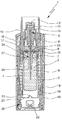
図1及び図2は、流体2、特に、効能の高い医薬組成物等を噴霧化する公知のネブライザ1を示しており、このネブライザは、非引張り操作状態(図1)及び引張り操作状態(図2)で概略的に示されている。ネブライザ1は、特に、携帯型吸入器として構成され、好ましくは、機械的にのみ且つ/或いは推進ガスなしで動作する。
1 and 2 show a
流体2、好ましくは液体、特に医薬組成物を噴霧化すると、エーロゾル14(図1)が生じ、かかるエーロゾルは、ユーザにより吸息又は吸入可能である。通常、吸入は、患者の苦しんでいる病訴又は病気に応じて、好ましくは定められた間隔で1日に少なくとも1回、特に1日に数回行われる。
Nebulization of
ネブライザ1は、流体2を収容した挿入可能な又は交換可能な容器3を備え又は有する。かくして、この容器3は、噴霧化されるべき流体2のリザーバを形成している。好ましくは、容器3は、最高200回の投与単位をもたらし、即ち、最高200回のスプレー又は塗布を可能にするのに十分な多数回投与分の流体2又は有効物質を収容している。国際公開第96/06011(A1)号パンフレットに開示されているような典型的な容器3は、約2〜20mlの量を収容する。
The
注目されなければならないこととして、投与量は、特に流体2又は薬剤に応じて様々な場合がある。ネブライザ1をそれぞれ適合させることができる。
It should be noted that the dosage may vary, particularly depending on
さらに、容器3内に入っている投与分の数及び/又は容器3内に入っている流体2の全量は、流体2又はそれぞれの薬剤に応じて且つ/或いは容器3に応じて且つ/或いは必要な薬物治療に応じて様々な場合がある。
Furthermore, the number of doses contained in the
好ましくは、容器3を交換し又は取り替えることができ、同じネブライザ1と共に使用できる容器3の個数は、好ましくは、例えば全部で4つ又は5つの容器3に制限される。
Preferably, the number of
容器3は、実質的に円筒形又はカートリッジの形状をしており、ネブライザ1をいったん開けると、容器を吸入器内に下から挿入でき、所望ならば交換することができる。この容器は、好ましくは剛性構造のものであり、流体2は、特に、容器3内の折り畳み式袋4内に保持される。
The
ネブライザ1は、流体2を特にあらかじめ設定され、オプションとして調節可能な投与量で運搬して噴霧化する圧力発生器5を有する。ネブライザ又は圧力発生器5は、好ましくは、容器3を解除可能に保持するホルダ6、ホルダ6と関連した駆動ばね7(部分的にしか示さず)及び/又は好ましくは手動による作動又は押し下げのためのボタンの形態又はかかるボタンを備えた制止要素8を有し、この制止要素は、ホルダ6を捕捉して制止することができ、かかる制止要素8を手動で操作するとホルダ6を解除することができ、それにより駆動ばね7を拡張させることができる。ネブライザ1又は圧力発生器5は、好ましくは、運搬要素、例えば運搬管9、逆止弁10、圧力チャンバ11及び/又は流体2をマウスピース13中に噴霧化するノズル12を更に有する。完全に挿入された状態の容器3は、ホルダ6によりネブライザ1内に固定され又は保持され、運搬管9が、容器3を穿刺するようになっている。ホルダ6は、好ましくは、容器3を交換することができるよう構成される。
The
駆動ばね7を軸方向に引張り操作すると、ホルダ6が容器3及び運搬管9と共に図面において下方に動かされて流体2が容器3から吸い出され、逆止弁10を通って圧力発生器5の圧力チャンバ11内に吸い込まれる。この状態では、ホルダ6は、駆動ばねが圧縮状態のままであるよう制止要素8によって捕捉される。この場合、ネブライザ1は、いわゆる作動又は引張り操作状態にある。
When the
制止要素8の作動又は押圧後における噴霧化プロセスの次の弛緩中、圧力チャンバ11内の流体2は、今や閉鎖状態にある逆止弁10を備えた運搬管9が駆動ばね7の弛緩又は力により圧力チャンバ11内で戻され、この場合、図面では上方に動かされ、今や加圧ラム又はピストンとして働く。この圧力により、流体2は、ノズル12中に送り込まれ、次に、図1に示されているようにエーロゾル14の状態に噴霧化される。
During the subsequent relaxation of the nebulization process after activation or pressing of the
一般に、ネブライザ1は、流体2に加わるばね圧力が5〜200MPa、好ましくは10〜100MPaであると共に/或いは一ストローク当たりの送り出し流体量が10〜50μl、好ましくは10〜20μl、最も好ましくは約15μlの状態で動作する。流体2は、エーロゾル14に変換され又はエーロゾル14として噴霧化され、かかるエーロゾルの液滴の空気力学径は、最大20μm、好ましくは3〜10μmである。好ましくは、発生するジェットスプレーの角度は、20°〜160°、好ましくは80°〜100°である。これらの値は、特に好ましい値として本発明の教示に従って構成されるネブライザ1にも当てはまる。
In general, the
ユーザ(図示せず)は、エーロゾル14を吸入することができ、好ましくは、その間、少なくとも1つの空気供給開口部15を通って供給空気をマウスピース13内に吸い込むことができる。
A user (not shown) can inhale the
好ましくは、ネブライザ1又は駆動ばね7を手動で、特に作動部材の作動によって作動させ又は引張り操作することができる。
Preferably, the
ネブライザ1は、好ましくは、上側ハウジング部品16及びこの上側ハウジング部品に対して回転可能な内側部品17を有し(図2)、内側部品は、上側部分17a及び下側部分17bを有し(図1)、他方、特に手動操作可能なハウジング部品(下側ハウジング部品)18が、好ましくは保持要素19によってこの内側部品17に解除自在に取り付けられ、特にこれに装着され又は保持されている。好ましくは、ハウジング部品16,18は、ネブライザ1のハウジングを形成する。容器3を挿入すると共に/或いは交換するために、ハウジング部分18をネブライザ1又はそのハウジングから取り外すことができる。
The
作動部材、特にハウジング部品18を、これと共に内側部品17を支持し又は駆動する上側ハウジング部品16に対して作動させ、この場合、回転させることができる。その結果、駆動ばね7は、内側部品17、特にその上側部分17aとホルダ6との間に形成されていて、ホルダ6に作用する歯車又は伝動装置(図示せず)によって軸方向に引っ張られる。引張り操作中、容器3は、容器3が図2に示すような端位置を占めるまで軸方向下方に動かされる。この作動又は引張り操作状態では、駆動ばね7は、張力下にあり、この駆動ばねを制止要素8によって捕捉し又は保持することができる。噴霧化プロセスの際、容器3を駆動ばね7によってその元の位置(図1に示されている非引張り操作位置又は状態)に戻す。かくして、容器3は、引張り操作中及び噴霧化プロセス中、持ち上げ又はストローク運動を行う。
The actuating member, in particular the
ハウジング部分18は、好ましくは、キャップ状の下側ハウジング部品を形成し、容器3の下方自由端部周りに又はこれに嵌まっている。駆動ばね7を引っ張ると、容器3は、その端部分と共にハウジング部品18内へ(更に)動き又はその端面に向かって動き、他方、ハウジング部品18内に設けられた通気手段、例えば軸方向に作用するばね20が、容器のベース(底)21に接触し、容器が最初に穿刺要素19に接触すると、このばねは、穿刺要素22により容器3又はこれに設けられたベースシールを穿孔し、空気を取り込み又は通気させることができる。
The
ネブライザ1は、好ましくは、カウンター装置23を有し、このカウンター装置は、好ましくはハウジングの上側ハウジング部品16に対する内側部品17のその引張り操作又は回転を検出することによってネブライザ1の作動を計数する。好ましくは、カウンター装置23又は関連のロックは、或る特定の回数の作動又は動作若しくは放出された投与量に達し又はこれを超えた場合、ネブライザ1の作動又は使用(それ以上の作動又は使用)を制止し、例えば、ハウジング部品18/内側部品17のそれ以上の回転を制止し、かくして、ネブライザ1又はその駆動ばね7の引張り操作を制止すると共に/或いは制止要素8の作動を制止する。
The
次に、図3〜図5を参照して吸入器又はネブライザ1の好ましい構成及び作動モードについて説明するが、図1及び図2のネブライザ1との本質的な差についてのみ強調する。かくして、図1及び図2に関する説明は、好ましくはそのまま又は類似した仕方で当てはまり、他方、図1及び図2のネブライザ1と以下に説明するネブライザ1の特徴の任意所望の組み合わせが可能である。
A preferred configuration and mode of operation of the inhaler or
好ましくは、容器3は、あらかじめ収納されている。これは、特に、国際公開第2006/125577(A2)号パンフレットに示されているように又は以下に説明するように実現できる。
Preferably, the
図3は、ネブライザ1を依然として閉鎖状態の好ましくはあらかじめ収納された容器3を備えた出荷状態で示している。この状態では、ネブライザ1のハウジングは、完全には閉鎖されておらず、特にハウジング部品18は、内側部品17に完全には押し付けられていない。図4及び図5は、ネブライザ1をハウジングが完全に閉じられ、容器3が開かれている作動状態で示している。図4では、ネブライザ1又は駆動ばね7は、引張り操作され、即ち、容器3は、その下方位置にある。図5は、ネブライザ1を非引張り状態で、例えば、流体2の1回投与分の小出し又は噴霧化後の状態で示しており、容器3は、その上方位置にある。
FIG. 3 shows the
容器3は、小出しされるべき流体2を出力する流体出口24を有している。特に、流体出口24により、一方において容器3又はその袋4と他方においてネブライザ1、その圧力発生器5又は運搬要素との間の流体結合が可能である。
The
流体出口24は、内側のクロージャ25を有し、この内側クロージャは、好ましくは、隔膜、メンブレン、プラスチックシール等で作られると共に/或いは容器3の内部に設けられる。オプションとして、1つの共通要素、特に運搬要素又は運搬管9等によって且つ/或いは穿刺によって連続開放が可能であるように第2の又は外側のクロージャ26が設けられるのが良い。
The
好ましくは、第1の又は内側のクロージャ25は、容器3の出口又はヘッド側端部から容器3又は袋4中に延びるクロージャ部分27によって形成され又は支持される。第2の又は外側のクロージャ26は、好ましくは、容器3のヘッド側又は軸方向端部に隣接して配置されると共に/或いはフランジ28に対して保持され又はこれに連結され、フランジ28は、クロージャ部分27又は任意他の適当な部分により形成されるのが良い。しかしながら、他の構成上の手段が採用可能である。
Preferably, the first or
図3の出荷状態では、容器3は、ネブライザ1内にあらかじめ収納され、即ち、挿入されている。しかしながら、容器3又はその流体出口24はまだ開かれていない。特に、第2のクロージャ26は、既に開かれているが、第1のクロージャ25はそうではない。これは、特に、出荷状態では、ネブライザ1のハウジングが部分的にしか閉じられておらず、即ち完全には閉じられていないので達成される。
3, the
特に、容器3は、特に輸送ロック29によってハウジング部品18に取り付けられ若しくはこれによって保持され又はこれに固定され、輸送ロック29は、好ましくはハウジング部品18内に配置され又はこのハウジング部品18のところに配置される。輸送ロック29は、特にハウジング部品18をネブライザ1に取り付ける前に且つ/或いは出荷状態において容器3を好ましくは一時的に保持する。特に、輸送ロック29は、容器3の流体結合中及び/又はこの場合ホルダ6との容器3の機械的連結中、容器3を固定状態に保持する。好ましくは、輸送ロック29は、容器3の開放中、特にその穿刺中、容器3を固定状態に保持する。
In particular, the
ネブライザ1がユーザのもとに輸送し又は送り届けることができ又は依然として包装している出荷状態では、ネブライザ1又はハウジング部品18は、好ましくは、特に安全確保部材30、例えば小旗(banderole )によって固定され、容器3及び/又はハウジング部品18は、ネブライザ1又は上側ハウジング部品16から十分に間隔を置いた状態に保持されると共に/或いは完全に閉じられ或いは運搬要素若しくは管9、ハウジング又は内側部品17等に完全に挿入され又はこれに嵌められることがないように且つ/或いは容器3、即ち、第1のクロージャ25の開放(完全な開放)が阻止されるようになっている。
In the shipping state in which the
安全確保部材30をいったん取り外すと、ユーザ(図示せず)は、運搬要素又は運搬管9を挿入することによってハウジング部品18を軸方向に完全に押すことができ、それにより容器3、即ち第1のクロージャ25を開くことができる。図4及び図5は、ハウジング部品18が完全に押されると共に/或いは容器3が開かれた(ネブライザ1若しくはその圧力発生器5又は運搬要素若しくは管9に流体結合される)この作動状態を示している。
Once the security member 30 has been removed, the user (not shown) can push the
図4は、ネブライザ1又は容器3を作動状態で示しており、容器3、即ち第1のクロージャ25が開いており、即ち、容器3又はその流体2は、ネブライザ1又はその圧力発生器5に流体結合され、ハウジング部品18は、軸方向に完全に押されている。ホルダ6を容器3のヘッド端部に係合(完全に係合)させて、吸引/引張り操作及び押圧ストロークのために容器3を後及び/又は前に動かすことができるようにするため、最初にネブライザ1又は駆動ばね7を引張り操作することが必要な場合がある。この引張り操作プロセス中、ホルダ6を運搬管9と一緒にハウジング部品18に向かって又はこの中に軸方向に動かし、かくしてホルダ6を容器3に係合(完全に係合)させると共に好ましくは容器3を動かしてハウジング部品18のベースの付近で穿刺要素22に押し付け、それにより容器ベース21に設けられているガス抜き穴31を穿刺し又は開く。図4は、ネブライザ1をこの引張り操作且つ作動状態で示している。ホルダ6は、容器3に係合し、運搬管9は、容器3内に完全に挿入されている。
FIG. 4 shows the
図5は、ネブライザ1を弛緩且つ非引張り状態で、即ち、流体2の1回投与分の噴霧化又は放出後の状態で示している。ホルダ6及び容器3は、上方位置にある。ホルダ6は、容器3と依然として係合しており、ネブライザ1の次の使用中、係合状態のままである。さらに、容器3は、依然として開いていると共に流体結合されており、即ち、ネブライザ1は、作動状態のままである。
FIG. 5 shows the
ネブライザ1の出荷状態で容器3、特に第1のクロージャ25の望ましくない開放を阻止するため且つ/或いはネブライザ1の完全閉鎖前に関連のハウジング部品18に対する容器3の運動(軸方向運動)を阻止するため、好ましくは、輸送ロック29が設けられている。輸送ロック29は、例えば、摩擦係合、強制係合又はインターロック係合により、容器3が望ましくないことにネブライザ1内で軸方向に動くのを阻止する。
In order to prevent the
好ましくは、輸送ロック29の開放は、ネブライザ1又はそのハウジングを完全に閉じたときに、即ち、ハウジング部品18を上側ハウジング部品16に向かって完全にスナップ装着し又は押し嵌めした(押して嵌めた)ときに自動的に起こる。この(軸方向又は入れ子式)閉鎖運動中、輸送ロック29が開かれ、容器3は、好ましくは容器を穿刺し又は開封している間又はその後に且つ/或いは好ましくは運動の最後の部分でのみ且つ/或いは最終の完全に閉じられた位置に達するほんの直前に又は最終の完全に閉じられた位置にちょうど達したときに軸方向に解除される。
Preferably, the opening of the
閉鎖運動中、輸送ロック29は、好ましくは、ネブライザ1のハウジング、内側部品17又はその下側部分17b等との直接的若しくは間接的相互作用又はこれらによる作動によって開かれる。好ましくは、容器3及び/又は第1のクロージャ25は、共通の作動手段、この場合、ネブライザ1若しくはそのハウジング又は下側ハウジング部品18の閉鎖運動によって輸送ロック29と共に開かれる。
During the closing movement, the
図4及び図5は、輸送ロック29を開放位置で、即ち、容器3が軸方向に自由に動くことができる状態で示している。
4 and 5 show the
以下において、別の図を参照して本発明のネブライザ1の好ましい実施形態について詳細に説明し、この場合、上述し又は図1〜図5に示されたネブライザ1との本質的な差異についてのみ強調し又は説明する。かくして、図1〜図5に関する説明は、好ましくはそれに準じて又は類似の仕方で当てはまり、他方、特徴の任意所望の組み合わせが可能である。
In the following, a preferred embodiment of the
図6は、まだ取り付けられていない、即ち分離状態の(下側)ハウジング部品18(説明の目的上、部分的に切除状態で開かれている)が関連の容器3を備えた状態でネブライザ1を側面側斜視図で示している。容器3は、まだネブライザ1内に挿入されておらず又はあらかじめ収納されてはいない。換言すると、ネブライザ1は、まだ組み立てられておらず又はまだ好ましい出荷状態にはない。
FIG. 6 shows the
図7は、ネブライザ1を概略断面図で示すと共にネブライザ1(ネブライザ1の上側部品)から依然として分離された容器3及びハウジング部品18を示している。
FIG. 7 shows the
ネブライザ1又はそのハウジング若しくはハウジング部品18は、好ましくは、種々の機能を有することができる安全確保装置32を有する。安全確保装置32は、流体2の運搬、圧力発生及び/又は噴霧化のために完全に閉鎖されたハウジング内に前後に動くことができるよう容器3を保持することができ、安全確保装置32は、容器3がハウジング又はハウジング部品18から分離できないようにするのが良い。かくして、それぞれの容器3と一緒にハウジング部品18の完全な交換しか可能ではない。代替的に又は追加的に、安全確保装置32は、輸送ロック29を形成することができる。代替的に又は追加的に、安全確保装置32は、使用済み容器3及び/又は使用済みハウジング部品18をもう一度ネブライザ1に連結する(再連結する)ことができ又はネブライザ1と共に使用することができるのを阻止することができる。
The
安全確保装置32又は輸送ロック29を閉じると、容器3は、運搬要素又は管9を挿入することによって開放可能に保持され又は当接支承され、好ましくは、運搬要素若しくは管9と容器3若しくはクロージャ部品27との間に圧力嵌め関係が生じると共に/或いは容器3は、容器(ヘッド)をホルダ6に連結する(完全に連結する)ために保持され又は当接支承される。換言すると、輸送ロック29又は安全確保装置32は、好ましくは、ネブライザ1の閉鎖中、容器3の当接支承手段となる。
When the
安全確保装置32又は輸送ロック29を閉じると、容器3は、穿刺要素22とは間隔をおいた状態で保持される。
When the
安全確保装置32は、図6及び図7に示されているようにハウジング部品18のところ又はこの中に配置され、取り付けられ又は固定されている。
The
好ましくは、安全確保装置32は、金属及び/又は打抜き加工部品を含み又はこれから成ると共に/或いは図7に示されているように単一の一体形部品から成る。好ましくは安全確保装置32は、鋼、特にばね鋼で作られる。好ましくは、安全確保装置32は、切断、打抜き加工等及び/又は曲げ加工によって板状材料から作られる。好ましくは、安全確保装置32又はその一部は、ケージを形成し、特に容器3又はその端部分、特に容器ベース21を包囲する。
Preferably, the
好ましくは、安全確保装置32は、保持要素33及び/又はロック要素34を有する。要素33及び/又は要素34は、好ましくは、アーム、指、葉等のように設計されている。具体的に言えば、要素33,34は、容器3の周囲全体にわたって交互に分布して配置されている。好ましくは、安全確保装置32は、多数の保持要素33及び多数のロック要素34、特に3つ又は4つ以上の保持要素33及び3つ又は4つ以上のロック要素34を有している。好ましくは、要素33,34は、少なくとも本質的に軸方向に且つ/或いは容器3の前後運動の方向に且つ/或いはネブライザ1の長手方向又は主広がり方向に又はエーロゾル14の主小出し方向に延びている。
Preferably, the
好ましくは、要素33,34は、図8に示されているように安全確保装置32のベース35によって保持され又はこれに連結されている。図8は、ネブライザ1を概略側面図で示しており、この場合、ハウジング部品18が既に部分的に取り付けられると共に幾つかの部分が切除されている。輸送ロック29又は安全確保装置32は、依然として閉じられ又はロックされ、即ち、容器3は、これを軸方向に動かすことができないよう依然としてしっかりと保持されている(軸方向という用語は、前後運動又はストローク運動の方向を意味している)。
Preferably, the
好ましくは、安全確保装置32又はベース35は、容器3を穿刺し、即ち、作動且つ引張り操作状態で、即ち、容器3がその下方端位置に達したときに、容器ベース21若しくはそのガス抜き穴31又は容器3のそれぞれのシール等を開く穿刺要素22を有し又は保持する。図示の且つ好ましい実施形態では、穿刺要素22は、安全確保装置32又はそのベース35のばね部分36を曲げることにより形成される。ばね部分36は、ホルダ6への容器3の連結(完全な又は最終的な連結)を支援し又は容易にすることができる。
Preferably, the
安全確保装置32又はベース35は、好ましくは、安全確保装置32をネブライザ1又はハウジング若しくはハウジング部品18のところ又はこの中に取り付ける少なくとも1つ又は多数の固定部分37を有している。特に、固定部分37は、安全確保装置32をハウジング部品18内に押し込むと、ハウジング部品18の側壁と協働することにより安全確保装置32を固定することができる。しかしながら、安全確保装置32、そのベース35、固定部分37等を複合成形することも又可能である。さらに、安全確保装置32は、ハウジング部品18等に任意他の適当な仕方で、特に別個の固定部材により又は接着等により連結されても良い。
The
上述したように、安全確保装置32は、好ましくは、容器3をネブライザの出荷状態では且つ/或いはネブライザ1のハウジング部品18の取り付け前において、ハウジング又はハウジング部品18内で動くことができないよう保持する輸送ロック29を形成する。この状況では(特に、出荷状態では)、容器3又は好ましくは半径方向に突き出ると共に/或いは円周方向に延び、好ましくは容器ベース21のところに形成された部分又はその縁部38は、好ましくは、押込み嵌め状態で且つ/或いは保持要素33とロック要素34との間、特に、図6〜図8に示されているように要素33,34のそれぞれの成形又は曲げ端部分33a,34a相互間に保持される。
As described above, the
図示の実施形態では、容器3及び/又は縁部38は、端部分33a,34a相互間に、好ましくは交互に捕捉される。保持要素33及び/又は端部分33aは、縁部38を掴み又はこの上に延び、ロック要素34又はその端部分34aは、縁部38を掴み又はこの下に延び、その結果、縁部38及び容器3は、これらの間に、特に押込み嵌めによってしっかりと保持され、それによりこの状態で、即ち、輸送ロック29/安全確保装置32がロックされた状態で、安全確保装置32及び関連のハウジング部品18に対する容器3の軸方向運動が阻止される。
In the illustrated embodiment, the
好ましくは、端部分33a及び端部分34aは、爪のように形成されると共に/或いは半径方向内方に延びる。
Preferably, the
好ましくは、要素33及び/又は要素34は、その自由端部が半径方向外方に撓むことができる。
Preferably,
好ましくは、安全確保装置32は、関連の容器3をそれぞれの軸方向力又は運動によって安全確保装置32に連結することができるよう設計され、要素33及び/又は要素34は、好ましくは、図6〜図8に示されているように要素3をロック位置で受け入れるよう必要に応じて好ましくは自動的に外方に撓む。しかしながら、必要ならば、必要に応じて組み立てのために代替的に又は追加的に適当な工具(図示せず)等を用いることができる。
Preferably, the
例えば、端部分33aの端部は、容器3をそれぞれの軸方向運動によって安全確保装置32中に挿入することができ又はこれに連結することができて保持要素33が縁部38の通過を可能にするよう外方に撓むように傾けられるのが良い。
For example, the end of the
好ましくは、保持要素33又はその端部分33aは、安全確保装置32からの及びかくして関連ハウジング部品18等からの容器3の分離を阻止する。
Preferably, the holding
この実施形態では、保持要素33は、好ましくは、端部分33aの上方で延びると共に/或いは好ましくはアーム状案内及び/又はロック部分33bを形成し又はこれら部分33bを有する。これら軸方向延長部及び/又はこれら部分33bは、端部分33aを越えて軸方向に延びると共に/或いは安全確保装置32と容器3との軸方向組み立て中に容器3又はその縁部38と協働することができ、その結果、保持要素33を外方に十分に撓ませて縁部38が端部分33aを通過することができ、そして容器ベース21をロック要素34の端部分34a上に着座させることができるようになっている。
In this embodiment, the retaining
ロック要素34は、好ましくは、その自由端部のところに設けられていて、端部分34aを軸方向に越えて延びる作動部分34bを有する。作動部分34bは、容器3を半径方向に案内することができると共に/或いはロック要素34の自由端部相互間への容器3又はその縁部38の挿入を容易にする。ただし、ロック要素34並びに保持要素33は、好ましくは、半径方向内方に付勢される。
The locking
容器3は、その縁部38が端部分33a,34a相互間に位置した状態で保持されると、輸送ロック29/安全確保装置32は、閉じられ、即ち、容器3は、ハウジング部品18又はネブライザ1内で軸方向に動くことができない。
When the
輸送ロック29又は安全確保装置32を開くため、ロック要素34及び/又はその端部分34aを好ましくは軸方向外方に撓ませて容器3が軸方向に自由に動くことができるようにし、特に、ロック要素34及び/又はその端部分34aは、縁部38が安全確保装置32内で軸方向にしか動くことができず且つ/或いは軸方向運動が保持要素33又はその端部分33aによって(図面では上方に)制限されると共に/或いは容器3を安全確保装置32から分離することができないよう制限される。輸送ロック29又は安全確保装置32のこの開放は、ネブライザ1を作動させたとき、最初にネブライザ1を用いたとき及び/又はネブライザ1を完全に閉じたときに起こる。すると、容器3は、特に前後に且つ/或いはこの実施形態ではその縁部38が端部分33aと穿刺要素22との間に位置した状態で軸方向に動くことができる。この状況は、図9の概略断面図に概略的に示されており、図9は、ハウジング又はハウジング部品18が閉じられると共に輸送ロック29/安全確保装置32が開かれた状態の噴霧化を示している。
In order to open the
図9には、容器3が図4に類似したその下方位置で示されており、特に、容器ベース21は、穿刺要素22と接触状態にある。しかしながら、ネブライザ1は、引張り操作状態では示されておらず、即ち、ホルダ6は、その下方位置にはなく、即ち、ホルダ6は、容器3の上側端部又はヘッドには依然として連結されていない。通常、ホルダ6は、この状況では、容器3が下方位置にある状態で容器3に連結される。換言すると、通常、ネブライザ1又は駆動ばね7を容器3が下方位置にある状態でこの状況において引張り操作する。
In FIG. 9, the
好ましくは、容器は、ネブライザ1を完全に閉じた後、最初にネブライザ1又はその駆動ばね7を引張り操作する際にホルダ6に最終的に又は完全に若しくは正確に連結される。しかしながら、一般的には、下側ハウジング部品18との組み立て(最初の組み立て)前又は中、ネブライザ1が引張り操作状態にあり、即ち、駆動ばね7が既に引張り操作され、ホルダ6が下方位置にあることも又可能である。それ故、ホルダ6は、ハウジング部品18を完全に閉じたときに容器3に直接接続されるべきであり、図9に示されている状況は、通常、起こるはずがない。
Preferably, after the
図9では、端部分34aは、輸送ロック29又は安全確保装置32を開くために半径方向外方に動かされる。これは、好ましくは、ロック要素34を半径方向外方に撓ませることによって達成される。これは、特に、作動部分34bに作用することによって達成できる。
In FIG. 9, the
好ましくは、ネブライザ1又はそのハウジング部品18を完全に閉じるときに、特に、内側部品17、その下側部分17b、保持部品39及び/又は安全確保部品40との協働又は当接によって輸送ロック29を開き又はロック要素34を外方に撓ませる。保持部品39は、好ましくは、上側ハウジング部品16又は内側部品17のところに配置される。安全確保部品40は、好ましくは、下側ハウジング部品18内に配置される。
Preferably, when the
保持部品39は、駆動ばね7の端部(下端部)を保持し、支承し又は支持するために内側部品17又はその下側部分17bの下端部又は自由端部に連結される。図3〜図5は、保持部品39の好ましい構造を示している。保持部品39は、好ましくは、リングとして形成されると共に/或いは内側部品17との相互連結のためにフック等を備えている。好ましい実施形態では、保持要素19は、保持部品39の一体コンポーネント又は部分を形成する。しかしながら、他の構成上の手段が採用可能である。
The holding
図3〜図5に示されている実施形態では、好ましくはリング状の安全確保部品40が容器3の軸方向運動を可能にするよう輸送ロック29、特に輸送ロック29の可撓性アームを開く。この安全確保部品40は、ネブライザ1又はそのハウジング部品18を完全に閉じると、輸送ロック29又はその可撓性アームを開き状態に保つ。安全確保部品40は、ネブライザ1を完全に閉じる際にハウジング部品18内での内側部品17又は保持部品39の当接によって軸方向下方に押される。
In the embodiment shown in FIGS. 3 to 5, the
図6〜図15に示され、特に図9に示されている好ましい実施形態では、ネブライザ1、ハウジング部品18又は安全確保装置32は、輸送ロック29/安全確保装置32又はそのロック要素34を開く好ましくはリング状の安全確保部品40を有する。特に、安全確保部品40は、ネブライザ1を閉じる際に軸方向下方に押され、その結果、安全確保部品40は、ロック要素34又はその作動部分34b相互間で動かされて軸方向力を半径方向外方に及ぼすようになる。好ましくは、傾斜平面が軸方向又は閉鎖運動を開放又は半径方向運動に変換し、かかる開放又は半径方向運動は、安全確保部品40をこの場合特に図9に示されている軸方向端位置において保持部品39の当接によって軸方向下方に押したときに作動部分34bを半径方向外方に押す。
In the preferred embodiment shown in FIGS. 6-15, and in particular in FIG. 9, the
好ましくは、安全確保部品40及び/又はロック要素34又は作動部分34bは、軸方向閉鎖運動又は安全確保部品40の運動をロック要素34又は作動部分34bの及びかくして端部分34aの所望の半径方向開放運動に変換して、特にハウジングを完全に閉じたとき又はハウジング部品18をネブライザ1に完全に押し付けたときに、輸送ロック29を開くようにするそれぞれの傾斜案内面(図示せず)等を有する。
Preferably, the
しかしながら、ネブライザ1又はそのハウジング部品18を閉じる際に輸送ロック29又は安全確保装置32若しくはそのロック要素34若しくは端部分34aの開放を実現するために他の構造上の手段が採用可能である。
However, other structural means can be employed to achieve the opening of the
好ましい実施形態では、安全確保部品40は、代替的に又は追加的に、別の目的に役立つ。即ち、安全確保部品40は、ネブライザ1を最初にそのハウジング部品18と組み立てる前に、ロック部分33bが半径方向に動いて離れ又は半径方向外方に撓むのを阻止する。
In a preferred embodiment, the
上述したように、安全確保装置32は、好ましくは、容器3をもう一度ネブライザ1に連結することができ又はネブライザ1と一緒に使用することができるのを阻止する。特に、安全確保装置32は、使用済みハウジング部品18又は使用済み容器3をこれがいったんネブライザ1から取り外されると、ネブライザ1に再び連結することができるのを阻止することができる。かくして、安全確保装置32は、容器3の望ましくない再使用及び/又はハウジング部品18とその好ましくは分離できない容器3との望ましくない再使用を阻止する。
As mentioned above, the
この実施形態では、ロック部分33bが少なくとも使用済み容器3及び/又はハウジング部品18をネブライザ1から取り外した後に押し離され又は互いに離れ又は半径方向及び/又は外方に動いて使用済み容器3及び/又はハウジング部品18をもう一度ネブライザ1に連結することができず又はネブライザ1と一緒に使用することができないという点において望ましくない再使用が阻止される。好ましくは、ロック部分33bは、ロック部分33bが解除後に押し離され又は半径方向及び/又は外方に動くよう付勢される。
In this embodiment, the locking
好ましい実施形態では、ロック部分33bは、容器3及び関連のハウジング部品18を最初にネブライザ1に連結する前に安全確保部品40(図7に概略的に示されている)によってロック部分33bを互いに保持し又は互いに離れ、半径方向及び/又は外方に動くことがないよう保持する。この予備組み立て状態では、安全確保部品40は、好ましくは、ロック部分33bの自由端部の近くに配置されると共に/或いは安全確保部品40は、ハウジング部品18をネブライザ1又はその内側部品17、特に下側部分17b上に軸方向に押したときにロック部分33bが、その自由端部が保持部品39及び/又は駆動ばね7内に位置した状態で挿入されるよう互いに十分に近接して保持されるようロック部分33bを包囲する。
In a preferred embodiment, the locking
安全確保部品40は、好ましくはロック部分33b又はその突出部33c(図9に示されている)と協働することができ、その結果、安全確保部品40は、ロック部分33b又は保持要素33を予備組み立て状態に互いに保持するその位置(上方位置)で好ましくは半径方向係合及び/又は摩擦力によって保持されるようになる。あとで、組み立て中、特に、ハウジングの完全な閉鎖中又はハウジング部品18を押している際、ロック部分33bは、保持部品39及び駆動ばね7内で動かされ、安全確保部品40は、軸方向下方に又は安全確保装置32、容器ベース21及び/又はハウジング部品18の端部の下側部分に向かって動かされる。すると、図9に示されているように端位置又は完全組み立て位置に達する。この状態では、半径方向に付勢されたロック部分33bは、安全確保部品40がもはやロック部分33bを互いに保持していないので、駆動ばね7によって互いに結合される。
The
好ましくは、安全確保部品40は、閉鎖運動の最後の部分で又は上述したようにネブライザ1を完全に閉じたちょうどそのときに輸送ロック29又はロック要素34を開いている。
Preferably, the
図10の概略断面図は、容器3を用いてネブライザ1から分離した後におけるハウジング部品18をその関連容器3と一緒に示している。安全確保部品40は、好ましくはその下方位置に位置したままである。輸送ロック29は、開いている(依然として開いている)。容器3は、その上方位置で示され、この上方位置では、容器3は、容器3をネブライザ1、特にホルダ6及び運搬要素又は管9から取り外したときに保持要素33の端部分33aによって保持される。
The schematic sectional view of FIG. 10 shows the
図10は、ロック部分33bが特にその付勢又は弾性力によって押し離され、この場合、特にその好ましくは半径方向の付勢又は弾性力によりその自由端部が半径方向外方に動かされている。ロック部分33bのこの押し離し位置は、容器3及び/又はハウジング部品18及び/又は安全確保装置32とネブライザ1の再結合を制止する。かくして、使用済みの容器3を再使用することができない。かくして、容器3又はネブライザ1の誤用を阻止することができる。
FIG. 10 shows that the locking
安全確保部品40は、更に、安全確保部品40が図9及び図10に示されているようにその下方位置にあるとき、保持要素33又はその端部分33aが半径方向に開かないように万全を期すことができる。この場合、安全確保部品40は、外方撓みを阻止し又は制限するよう保持要素33の好ましくは外側部に接触する。かくして、安全確保装置32又はその保持要素33若しくは端部分33aは、開くことがないようになり、その結果、容器3又はその縁部38は、安全確保装置32内に又は安全確保装置32若しくは保持要素33によって形成されたケージ内にしっかりと保持される。
The
好ましい実施形態では、カウンター装置23は、好ましくは図7〜図10に概略的に示されているようにハウジング部品18のところに配置される。カウンター装置23は、ネブライザ1の作動若しくは動作又は放出された投与分を計数する。好ましくは、カウンター装置23は、ハウジングの上側部品16に対する内側部品17の回転を検出することによって作動又は動作を計数する。換言すると、カウンター装置23は、ネブライザ1又はその駆動ばね7の引張り操作を計数することができる。しかしながら、他の構造的手段が採用可能である。
In a preferred embodiment, the
好ましくは、カウンター装置23は、関連の好ましくは一体形成された駆動歯車43を備えたねじ山付きスピンドル又はシャフト42を有している。カウンター装置23は、好ましくは、ねじ山付きシャフト42に関連すると共にねじ山付きシャフト42と協働するライダ44を更に有し、ライダ44は、ねじ山付きシャフト42を回転させるとねじ山付きシャフト42に沿って軸方向に動かされるようになっている。
Preferably, the
ねじ山付きシャフト42は、好ましくは下側ハウジング部品18内に回転可能に支承されると共に/或いは好ましくはネブライザ1の軸方向又は長手方向に且つ/或いは容器3の軸方向又はストローク運動方向に平行に延びている。
The threaded
駆動歯車43は、好ましくはねじ山付きシャフト42及び/又はハウジング部品18の上端部のところに配置され、特に、駆動歯車は、組み立て状態では、即ち、ネブライザ1のハウジングが図9に概略的に示されているように完全に閉鎖されているとき、ネブライザ1のハウジング又は上側ハウジング部品16の好ましくは内側の歯部45と噛み合うことができるようになっている。
The
カウンター装置23又はそのライダ44、特に、ねじ山付きシャフト42に沿うライダ44の軸方向位置は、既に実施され若しくは現在の容器3と共に用いられ又は依然として現在の容器3と共に実施できる引張り操作、作動又は投与分の作動回数又は投与回数を示し又は指示することができる。この作動回数を特に、ポインタ46及び/又は関連の目盛り等によって示すことができ、これらポインタ及び/又は関連の目盛り等は、ハウジング部品18の対応の窓又は透明な部分越しに適度に目に見える。注目されなければならないこととして、かかる作動回数は、正確に示されていない。特に、カウンター装置23、ライダ44又はそのポインタ46は、かかる作動回数の大まかな指標を与えるだけで十分であると言える。この目的のため、目盛りがかかる作動回数を大まかに指示する互いに異なる着色領域又は区分を示すに過ぎない場合であっても十分であると言える。さらに、注目されなければならないこととして、他の構造上の手段も又採用可能である。
The axial position of the
カウンター装置23は、好ましくは機械的に働く。これにより、極めて簡単且つ堅固な構造及び極めて確実な動作が可能である。
The
カウンター装置23は、ネブライザ1の好ましくはロック状態を制御し又は提供することができ、必要な容器交換及び/又は容器計数を指示する。この目的のため、モニタリング若しくはカウンター装置23又はライダ44は、好ましくは、図8に概略的に示されているような作動部分47を有する。作動部分47は、好ましくは、出張り状であると共に/或いは軸方向に且つ/或いは上側ハウジング部品16に向かって且つ/或いは上方に延びている。
The
カウンター装置23は、それぞれのハウジング部品18に関連しており、かくして、好ましくは、たった1つの容器3に関連しており、それぞれの容器3を用いたネブライザ1の作動を計数し、即ち、この容器3から取り出された又は依然として取り出すことができる流体2の投与分の数を(これのみを)計数する。
The
注目されなければならないこととして、第1の容器3を出荷状態において関連のハウジング部品18と一緒にあらかじめ収納することができる。この予備収納は、オプションである。好ましくは、更に別の容器3がネブライザ1と一緒に出荷され、この場合、各容器3は、関連ハウジング部品18と、かくして関連カウンター装置23と分離できないよう連結されている。好ましくは、カウンター装置23又は各ハウジング部品18のねじ山付きシャフト42は、設計上、阻止又は制動手段を備えていて、その結果、ハウジング部品18がネブライザ1に取り付けられる前に望ましくない計数又は回転が阻止されるようになっている。
It should be noted that the
ネブライザ1は、ネブライザ1により使用済みの又は依然として使用可能な容器3の個数を計数すると共に/或いは容器個数及び/又は容器交換及び/又は使用の終わりを指示する記号を指示し又は表示する装置48を有する。この装置48は、好ましくは、モニタリング及び/又はユーザ手引きのためのものである。
The
好ましくは、上述の回数及び/又は記号は、特に図6に概略的に示されているように上側ハウジング部品16内に設けられたネブライザ1の透明な部分又は窓49越しに見え又は示される。特に、かかる個数及び/又は記号は、ネブライザ1の側面のところに示される。他の構成又は構造上の手段が採用可能である。
Preferably, the above mentioned times and / or symbols are visible or shown over a transparent part or
図11は、下側ハウジング部品18及び容器3が省かれた状態のネブライザ1を概略側面図で示しており、この場合、上側ハウジング部品16の部分は、ネブライザ1のモニタリング又は案内装置48が良く見えるように切除されている。
FIG. 11 shows a schematic side view of the
ネブライザ1又は装置48は、好ましくは、容器個数、記号、状態及び/又は例えば容器交換に関するユーザ取り扱い説明を指示し又は表示すると共に/或いはネブライザ1のロック状態を制御する部材50を有している。かくして、部材50は、インジケータ部材及び/又は制御部材とも呼ばれる。好ましくは、両方の機能は、同じ又は単一の部材50によって達成される。しかしながら、インジケータ部材及び制御部材は、別々の部品又は多数の部品で形成されることも又可能である。好ましくは、以下の説明は、かかる広い意味において理解されるべきである。
The
好ましくは、ネブライザ1又は装置48は、部材50を駆動し又は動かし、特に回転させるばね51を有する。このばね51は、図7、図8、図9及び図11に示されている。好ましくは、部材50は、ばね力によってのみ又はばね51によって特に多数の段階をなして且つ/或いは初期(回転)位置から最終(回転)位置に駆動され又は回転する。
Preferably, the
ばね51は、好ましくは、螺旋、スリーブ状、リング状及び/又はねじりばね及び/又はレッグスプリング(leg spring)である。このばねは、好ましくは、被動部材50と同軸に且つ/或いはこれに隣接して配置される。
The
ばね51は、好ましくは、これが回転力を部材50に加えるよう付勢状態で設けられる。この目的のため、ばね51は、一方の端部又はレッグがネブライザ1、特に上側ハウジング部品16のところに位置した状態で支持され、このばねは、例えば部材50等の肩又は支承部分67(図12及び図13参照)を当接することによってその他方の端部又はレッグが部材50に係合する。
The
図12は、部材50の好ましい実施形態を概略側面図で示している。図13は、この部材50を斜視図で示している。
FIG. 12 shows a preferred embodiment of the
部材50は、好ましくは、一体形及び/又は成形部品によって形成されている。部材50は、好ましくは、少なくとも本質的にリング状であり、この部材は、好ましくは閉鎖リングを形成し又はかかる閉鎖リングから成る。
The
部材50は、容器個数を指示する数52及び/又は特に容器交換及び/又はネブライザ1の使用の終わりを指示するユーザ手引きのための記号53を有し又は備えている。好ましくは、数52及び記号53は、部材50上に示されると共に/或いは配置されており、1つ又は2つ以上の数52及び1つ又は2つ以上の記号53が交互に位置している。特に、好ましくは連続して並んだ数52相互間に1つ又は2つ以上の記号53が配置されると共に/或いは示されており、その結果、これら記号53は、例えば必要な容器交換、ネブライザ1の開放、ネブライザ1の閉鎖等を指示するようになっている。これは、記号53としてそれぞれ矢印、色、マーク等で伝えられ又は指示されるのが良い。さらに、最後の記号53は、ネブライザ1の使用の終わり又はネブライザ1の完全なロック状態を例えば“X”等で指示することができる。この記号53は、例えば、ネブライザ1と共に用いることができ又はネブライザ1内で用いることできる最後の容器3に関する、即ち、ネブライザ1の全又は最終ロック状態を指示するネブライザ1の許容動作又は作動回数に達し又はこれを超えると、示されるのが良い。この実施形態では、好ましくは少なくとも2つの互いに異なる記号53のシーケンスが互いに異なる又は連続して並んだ数52相互間に示される。記号53のこのシーケンスは、好ましくは、容器交換のためのネブライザ1の開放を指示する最初の又は第1の記号53(例えば、下向きの矢印)及び容器交換を完了させるネブライザ1の閉鎖を指示する次の又は第2の記号53(例えば、上向きの矢印)を有する。しかしながら、互いに異なる又は連続して並んだ数52相互間にたった1つの、潜在的に類似の又は同一の記号53、例えば容器交換を指示する1つの記号53を示すことも可能である。好ましくは、最後の容器3に関するネブライザ1の許容動作又は作動回数に達し又はこれを超えた時点及び/又はネブライザ1を最終的に制止した時点及び/又は挿入できる容器3がそれ以上ない時点でたった1つの専用又は終わりの記号53、例えば“X”が示される。
The
部材50は、好ましくは、この実施形態では半径方向突出部等により形成される係合又は停止部分54を含む。停止部分54は、好ましくは、部材50の段階的運動又は回転(割送り)を可能にし又は実現するよう用いられる。
The
部材50は、特に保持要素19を押し下げ又は半径方向内方運動を生じないように選択的に制止することによってネブライザ1又はハウジング部品18を開くことがないよう選択的にロックするために好ましくは軸方向に延びると共に/或いは保持要素19と協働する制止部分55を更に有する。
The
部材50は、好ましくは、ネブライザ1の関連のロック57を制御し又は駆動する制御部分56を有する。制御部分56は、好ましくは、突出部、凹み又は傾斜案内面等によって形成され、これら突出部、凹み又は傾斜案内面等は、好ましくは、半径方向に延びると共に/或いは好ましくは部材50又はそのリング部分の外周部上に形成される。しかしながら、他の配置も又採用可能である。
The
ロック57は、好ましくは、ロック部材58又はその一部分59によって形成され、このロック部材又はその一部分は、好ましくは、舌状、葉状であり且つ/或いは可撓性である。図14は、ロック部材58を斜視図で示している。図15は、ロック部材58を別の斜視図で示している。
The
ロック部材58は、好ましくは、金属で作られると共に/或いは板材料及び/又は打抜き加工部品等で形成される。ロック部材58は、好ましくは、リング状であると共に/或いはスリーブ状である。
The
部分59は、好ましくは、曲げられ若しくは凹まされ又は特に半径方向にかかる型を備えると共に/或いは部材50及び/又は制御部分56の少なくとも1つ若しくは2つ以上又は全てと協働するクリンプ、波形部60等を備え、特に、部分59は、部材50の回転運動又は位置に応じて、半径方向に、特に外方に撓むようになっており又はそうではないようになっている。例えば、制御部分56は、部分59から半径方向内方に延びる波形部60がこの波形部60の内側部に隣接して位置した部分56内に受け入れられた場合に部分59が半径方向外方に撓むことがないよう凹んでおり又は引っ込められている。部材50が別の回転位置にある場合、波形部60は、部材50の凹んでいない外周部に当接することができ、その結果、部分59が外方に撓むと共にロック57が閉じられるようになっている。かくして、ロック57は、特にその回転位置に応じて制御部材50によって駆動され又は制御され、即ち開閉される。
The
上述したように、装置48又は部材50は、好ましくは、ばね力によって、この実施形態では、ばね51の力によって駆動される。特に、部材50は、ばね51の力によって段階的に回転し又は割送りされ、部材50の段階的運動又は回転だけを保証するようラチェット又は停止機構体が設けられている。特に、停止手段は、部材50の停止部分54と係合する。この実施形態では、機構体又は停止手段は、好ましくは、1つ又は2つ以上の停止要素61により形成されている。停止要素61は、好ましくは、アームのように且つ/或いはロック部材58によって形成される。停止要素61は、好ましくは、停止部分54が選択的に通過することができるように、即ち、選択的に部材50が更に一ステップ割送りすることができ又は停止部分54を制止することができ、かくして部材50が更に回転しないよう制止することができるよう弾性変形可能である。好ましくは、停止要素61は、各停止要素61が停止部分54の運動経路中に延びて停止部分54がそれぞれの停止要素61を通過することができないよう停止位置に付勢される。
As mentioned above, the
好ましくは、少なくとも2つの停止要素61が設けられ、これら停止要素は、好ましくは、停止要素61を択一的に作動させて部材50が一ステップだけ、即ち、停止要素61を択一的に作動させ、例えば、特に軸方向及び/又は半径方向に撓ませて一停止部分54が通過することができるようにしたときに一回転運動又はひと刻みだけ更に割送りし又は動くことができるようにすることができる。停止要素61は、好ましくは、それぞれの停止部分54が通過することができるよう上方に撓む。停止要素61の作動について以下に詳細に説明する。
Preferably, at least two
停止要素61又はその自由端部は、特に停止要素又はアーム61をそれぞれ曲げることにより又は複合成形等を行うことによって広幅化当接又は係合本体又は表面を備えるのが良い。各停止要素61は、図8に概略的に示されているように接触要素61aを備えるのが良い。接触要素61aは、複合成形によって形成されるのが良く且つ/或いはシュー状であるのが良い。接触要素61aは、停止部分54のための停止部又は当接部を形成するのが良く、その結果、部材50は、停止要素61又は接触要素61aが制止位置、この場合、図8に示されている下方位置にあるときにばね51の力によってそれ以上回転しないよう制止されるようになっており、かかる下方位置では、1つの停止部分54は、接触要素61aに当接し、円周方向に通過することができない。この場合、停止要素61又は接触要素61aは、制止された停止部分54が通過することができ、そして部材50が円周方向に更に一ステップ割送りすることができるよう上方又は軸方向に動かされなければならない。
The
以下において、ネブライザ1の作動及び取り扱いについて詳細に説明する。
Hereinafter, the operation and handling of the
ネブライザ1をあらかじめ収納された容器3及びあらかじめ取り付けられたハウジング部品18を備えた状態で出荷されるのが良い。この場合、ネブライザ1又はそのハウジング部品18は、容器3がまだ流体結合されず又は開かれないよう完全に閉じられていない。
The
変形例として、ネブライザ1を別個の容器3及び別個のハウジング部品18を備えた状態で出荷しても良い。この場合、容器3及びハウジング部品18は、好ましくは、あらかじめ組み立てられ、即ち、ネブライザ1とは別個のユニットを形成する。
As a variant, the
いずれの場合においても、ネブライザ1は、好ましくは、多数の容器3、例えば4つ又は5つの容器3と一緒に出荷され、この場合、各容器3は、関連のハウジング部品18に分離できない状態で連結されている。容器3及びハウジング部品18のこれらユニットは、ネブライザ1を多数の容器3と共に次々に使用することができるよう交換可能である。
In any case, the
両方の場合において、容器3は、好ましくは、閉じられた輸送ロック29又は安全確保装置32によってハウジング部品18のところに又はハウジング部品18内に動くことができない状態で保持される。
In both cases, the
両方の場合において、ハウジング部品18は、好ましくは、例えばハウジング部品18の内周部に沿ってぐるりと分布して設けられると共に/或いは図10に概略的に示されているように軸方向に延びる1つ又は2つ以上の溝、突出部、リブ62等によってコーディングを有する。このコーディングは、ハウジング部品18に関連した容器3又はそれぞれの流体2に対応している。コーディングは、ネブライザ1のところ、特に内側部品17又は保持部品39のところの相補するコーディングに合致し、かかるコーディングは、好ましくは、それぞれ配置されると共に/或いは寸法決めされた凹み、特に図11に概略的に示されているように保持リング又は保持部品39によって又はこの保持リング又は部品39のところで形成されたコーディング部分63、例えば突出部、凹み、凹部等によって形成される。コーディングが互いに合致した場合にのみ、ハウジング部品18及びかくして容器3をあらかじめ収納することができると共に/或いはネブライザ1に連結する(完全に連結する)ことができる。
In both cases, the
ネブライザ1又はそのハウジング部品18を閉じる(完全に閉じる)前に、装置48又はインジケータ部材50は、それぞれの記号53、例えば上方に向いた矢印によってネブライザ1又はハウジング部品18が完全に閉じられたことを指示することができる。
Prior to closing (completely closing) the
ハウジング部品18を完全に閉じると、ハウジング部品18に関連した容器3をネブライザ1に流体結合する。これは、ネブライザ1又は装置48によって検出され又は記録される。ハウジング部品18及びかくして関連の容器3の連結のこの検出は、好ましくは、特に停止要素61のうちの1つを作動させて部材50が更に一ステップを割送りすることができるようにすることによって、即ち、他方の停止要素61が部材50のそれ以上の割送り又は回転を停止するまで、機械的に実現される。この実施形態では、この記録又は作動は、特に図7に示されているようにハウジング部品18のところ、特にその上側前面のところに形成された突出部64によって達成される。ネブライザ1を完全に閉じると、突出部64は、1つの関連の停止要素61又は接触要素61aに当接し、その結果、停止要素61又は接触要素61aを上方に撓ませてこれが部材50の対応の停止部分54をもはや停止させず、部材50は、更に一ステップ、即ち、この状態では撓んで係合状態から外れることがなかった他方の停止要素61が対応の停止部分54、好ましくは停止部分54のうちの別の1つを停止させることによってそれ以上の回転を停止させるまで、動き又は回転することができるようになる。
When the
上述したように、容器3は、好ましくは、ハウジング部品18、関連カウンター装置23及び/又は関連安全確保装置32から分離できない。かくして、新たな容器3とネブライザ1の連結後、関連のカウンター装置23は、既に実施され又は依然として実施することができる容器3の作動回数又は使用回数の計数を開始する。この作動回数を上述したようにカウンター装置23又はそのライダ44若しくはポインタ46によって指示し又は示すことができ、装置48又は部材50は、好ましくは、容器個数52、即ち、使用済みの又は依然としてネブライザ1と共に使用することができる容器3の個数だけを示す。
As mentioned above, the
好ましくは、ネブライザ1は、現在の容器3が空になる(十分に空になる)まで且つ/或いは所定の動作又は作動回数に達し又はこれを超えるまで開かないよう制止される。このようにネブライザ1又はそのハウジング部品18が開かないよう且つ/或いは容器交換が行われないよう制止することは、好ましくは、例えば図9に概略的に示されているようにこの状態では保持要素19の下に配置された部材50のそれぞれの制止部分55によって達成され、その結果、保持要素19を押し下げることができず、即ち、ネブライザ1を開くことができずしかもハウジング部品18を取り外すことができないようになる。
Preferably, the
ネブライザ1の所定の動作又は作動回数に達すると、ネブライザ1は、現在の容器3と共にそれ以上使用することができないよう制止される。この制止は、第1のロック状態とも呼ばれる。
When the predetermined operation or number of activations of the
第1のロック状態は好ましくはカウンター装置23によって始められる。特に、ライダ44又はその作動部分47は、装置48と協働して、現在の容器3について所定の作動回数に達し又はこれを超えたときに第1のロック状態を開始する。具体的には、ライダ44又はその作動部分47は、この状態において上方軸方向位置に達し、そして制止位置にあり又は停止部分54と係合関係をなしている停止要素61又は接触要素61aを作動させる。かくして、停止要素61又は接触要素61aは、好ましくは、先に停止させた停止部分54が通過することができ、そして部材50がばね51の力によって更に一ステップ自由に割送りすることができるよう撓み又は変形する。図8は、ライダ44及び作動部分47が既に上方位置の近くに位置し且つ関連の停止要素61又は接触要素61aを作動させる位置の近くに位置している状況を示している。しかしながら、図8に示されている状況では、一停止部分54及び部材50は、依然として、更に一ステップ回転しないよう制止されている。
The first locked state is preferably initiated by the
上述したように部材50を一ステップだけ割送りすることにより、第1のロック状態が得られる。この状態では、ネブライザ1又は保持要素19は、これを開くことができるよう非制止状態になる。先の状態において保持要素19の作動を制止している制止部分55は、更に動かされ、その結果、保持要素19がもはや制止されず、容器交換のためのハウジング部品18の取り外しを可能にするためにかかる保持要素19を作動させることができ又は押すことができるようになる。
As described above, the first locked state is obtained by indexing the
第1のロック状態では、ネブライザ1、装置48又は部材50は、好ましくは、容器交換が必要であると共に/或いはネブライザ1が現在の容器3についてそれ以上使用できないようになっていることを好ましくはそれぞれの記号53、特に下向きの矢印によって指示する。
In the first locked state, the
第1のロック状態に達するよう部材50を上述したように割送りすることにより、ネブライザ1は、それ以上使用できないようロックされる。これは、特に、部材50がロック57を駆動してネブライザ1をそれ以上作動しないよう、好ましくは、駆動ばね7のそれ以上の引張り操作を行わないよう且つ/或いはハウジング部品18の回転を行わないようロックするので達成される。これは、好ましくは、部材50の回転によりロック57又はロック部材58の部分59が半径方向外方に撓んで撓んだ部分59が付勢されているその非ロック位置を撓み部分59が出て上側ハウジング部品16に対する内側部品17のそれ以上の回転を制止するようになっているので実現される。このロックは、特に、部分59の自由端部がそれぞれの歯部に嵌まり込み又は上側ハウジング部品16の内面のところに形成されたそれぞれの当接面に当たるので達成される。この点に関し、注目されなければならないこととして、装置48は、好ましくは、内側部品17上に、特にその上側部分17a上に配置され又は取り付けられ、好ましくはリング状のロック部材58が好ましくは、回転可能な部材50回りに配置される。ロック部材58は、好ましくは、内側部品17又はその少なくとも1つの突出部17cがロック部材58の凹部65中に押込み嵌めすることによって内側部品17に対して回転しないようになっている。この実施形態では、凹部65は、好ましくは、一方の軸方向側部からの周囲の切欠き部分又はポケットのように形成される。特に、ロック部材58は、それぞれの突出部17c等、特に関連の内側部品17の係合のために図14及び図15に概略的に示されているように2つ又は3つ以上の凹部65を備えるのが良い。しかしながら、他の構造上の手段も又採用可能である。
By indexing the
その結果、部材50だけが内側部品17に対して、かくしてロック部材58に対して回転可能である。しかしながら、ロック部材58は、上側ハウジング部品16に対して内側部品17と一緒に回転可能である。
As a result, only the
上述したように、制御部材50は、ロック部材58に対して動くことができ、特に回転可能である。この相対回転は、制御部材50の回転又は割送りが言及される場合であることを意味している。この関係で、考慮されなければならないこととして、装置48及びロック部材58は、内側部品17と一緒に回転するが、この回転は、これがエネルギー貯蔵手段、この場合ばね7を引張り操作すると共に/或いは特に運搬要素又は管9の軸方向運動によって流体2を容器3から送り出す又は吸い出すための運動であるので、上述の回転とは異なっている。
As described above, the
上述した構成の結果として、装置48は、下側ハウジング部品18を回転するたびには、即ち、駆動ばね7を引張り操作する場合には内側部品17と一緒に回転する。この回転は、好ましくは、180°刻み又はステップで行われる。したがって、装置48又はインジケータ部材50は、好ましくは、窓49越しに交互に示される2つの組をなすそれぞれの数52及び/又は記号53を含む。
As a result of the configuration described above, the
かくして、部材50は、好ましくは、2つのグループをなす数52及び/又は記号53を含み、各グループは、数52及び/又は記号53のそれぞれのシーケンスを有し、グループは、部材50上に180°オフセットした状態で配置される。このオフセットは、ネブライザ1/駆動ばね7を引張り操作するために下側ハウジング部品18及び内側部品17の各回転作動のための回転角度に一致している。
Thus, the
好ましくは、制御部分56及び/又は制御部分56相互間の制御部材50の周辺部分は、部分59又はそのカム又は波形部60と協働する傾斜又は制御平面又は表面を形成し、その結果、ロック57又はロック部材を部材50に作用するばね51の力だけで作動することができるようになっている。特に、ばね51又は部材50は、ロック57を駆動する。さらに、部材50は、ロック57又はロック部材を制御する。部材50は又、インジケータ部材を形成するので、インジケータ部材は、ロック57又はロック部材も駆動する。
Preferably, the
この実施形態では、好ましくは、ロック部材58は、少なくとも制御部材50の円筒形主要部分周りで制御部材50の外側に又はこの周りに配置される。特に、ロック部材58は、少なくとも実質的に制御部材50の円筒形主要部分を包囲し又は覆う。ロック部材58は、好ましくは、内側部品17及びかくしてロック部材58の回転位置に応じて窓49と交互に整列する2つの開口部66(図14及び図15に示されている)を有し、したがって、それぞれの数52及び/又は記号53が窓49越しに且つロック部材58を介して見えるようになる。
In this embodiment, preferably the locking
第1のロック状態では、部材50は、好ましくは、突出部64によってそれ以上回転しないよう止められ、この場合、任意他の部分がハウジング部品18の取り付けに対応している。ハウジング部品18を容器交換のためにネブライザ1又はその上側ハウジング部品16若しくは内側部品17から取り外した場合、この取り外しは、部材50のそれ以上の運動又は回転を制止しないようにすることによって記録される。特に、突出部64等によって止められている部材50の停止部分54は、ハウジング部品18の取り外し後に通過することができ、その結果、部材50は、更に一ステップ割送りできるようになっている。この別の回転位置では、ネブライザ1は、依然としてその第1のロック状態にあり、即ち、それ以上使用できないよう、特に駆動ばね7のそれ以上の作動又は引張り操作を行うことができないよう依然としてロックされている。しかしながら、部材50は、新たな容器3をネブライザ1に連結しなければならず且つ/或いは新たなハウジング部品18をネブライザ1に連結しなければならないことを指示する次の記号53、特に上向きの矢印を示すことができる。この状況は、上述したネブライザ1とハウジング部品18の最初の組み立て前の当初の状況に対応している。
In the first locked state, the
注目されなければならないこととして、制止要素8は、好ましくは、作動しないよう、特に、第1のロック状態においてホルダ6及び駆動ばね7の解除が行えないよう制止される。この作動ロックは又、装置48又は部材50によって達成される。
It should be noted that the restraining
ハウジング18及び関連容器3を交換すると、これは、装置48によって、特に、突出部64による対応の停止要素61の作動によって記録される。次に、部材50は、更に一ステップ割送りし、この部材は、次の容器数52を示す。次に、ロック57をリセットし、即ち、再び開き又はロック解除する。かくして、ネブライザ1は、ロック解除され、そして新たな容器3と共に更に使用できる。それと同時に、容器3又はハウジング部品18は、好ましくは、特に次の制止部分55が保持要素19の下に位置決めされてネブライザ1を開放するのに必要な保持要素19の作動を阻止するので、開放又は容器交換が行えないよう再びロックされる。
When the
上述のシーケンスを繰り返し実施することができ、即ち、新たな容器3及び新たなハウジング部品18をネブライザ1と共に次々に使用することができ、装置48又はインジケータ部材50は、特に必要な容器交換を指示すると共に/或いはネブライザ1を開閉する等の指示を行うようユーザ手引きのための容器数52及び好ましくは記号53を表示し又は示す。容器数52は、特に、ネブライザ1と共に既に使用され又はネブライザ1と共に依然として使用できる容器3の数に関連している。特に、1つ又は2つ以上の記号53が連続して並んでいる容器数52と交互に表示され又は示される。これは、好ましくは、1つのコメントコンポーネント、即ちインジケータ部材50によって実現される。しかしながら、他の構造的実現が可能である。
The above sequence can be repeated, i.e.
さらに、容器数52及び/又は記号53の表示は、好ましくは機械的にしか働かない。
Furthermore, the display of the
特に、装置48及び/又はロック57は、機械的にしか働かない。
In particular, the
所定数の容器3をネブライザ1に連結した後、ネブライザ1は、それ以上の容器交換ができないよう制止される。最後に挿入され又は連結されて容器3を用いた後、ネブライザ1は、最終のロック状態、即ち、第2のロック状態に入り、好ましくは、ロック57又はネブライザ1は、リセットできないよう制止されると共に/或いはネブライザ又はハウジング部品18は、開くことができないよう制止される。この第2のロック状態は、特に最終の現在の容器3について所定の作動回数に達し又はこれを超えた後に始められる。上述のプロセスと同様、カウンター装置23又はそのライダ44若しくは作動部分47は、装置48、特に対応の停止要素61を作動させて部材50を更に一ステップ割送りしてこれをその最終回転位置に至らせることができるようにする。かくして、第2のロック状態に至る。
After connecting a predetermined number of
第2のロック状態では、制御部材50をそれ以上回転させることができない。これは、本発明では、特に、支承部分67が凹部65のうちの1つの中に嵌まり込んだ内側部品17の1つの突出部17cに当接するので実現される。しかしながら、所望の回転停止を実現し又は制御部材50について最終の回転位置、即ち、第2のロック状態に制止するために他の構成上の手段が採用可能である。
In the second locked state, the
第2のロック状態では、装置48又は部材50は、ネブライザ1又はハウジング部品18の開放を可能にしない。と言うのは、これは、第1のロック状態における場合にあるからである。これとは異なり、部材50は、保持要素19をそれ以上作動しないよう制止し、かくして、ネブライザ1を開いて容器を交換することができないよう制止するよう設計され、好ましくは十分に長い制止部分55を有する。
In the second locked state, the
第2のロック状態では、ネブライザ1は、それ以上作動しないよう、特に、駆動ばね7の引張り操作ができないよう且つ/或いはハウジング部品18又は内側部品17の回転ができないようロックされるのが良い。これは、ロック57を作動させることにより、特に、部材50又はその対応の制御部分56によって部分59を半径方向に(好ましくは外方に)撓ませることによって実現できる。第2のロック状態では、ネブライザ1は、好ましくは、特に制止要素8の作動を制止することによって、流体2をそれ以上放出させないようロックされる。これは又、好ましくは、装置48によって実現される。
In the second locked state, the
したがって、第2のロック状態に入った後はネブライザ1をそれ以上使用することができない。第2のロック状態は、可逆的ではない。特に、ロック57のリセット又はロック解除は、可能ではなく、第2のロック状態では阻止される。
Therefore, the
上述したように、好ましい実施形態としてのネブライザ1の幾つかの一般的な観点又は技術的思想を以下に示すように要約することができる。
As mentioned above, some general aspects or technical ideas of the
装置48は、好ましくは、2つの部分(制御部材50及びロック部材58)又は3つの部分(制御部材50、ばね51及びロック部材58)のみから成るが、多数の機能、特に、個数52及び/又は記号53及び/又はユーザ取り扱い説明の表示機能、ネブライザ1をそれ以上使用できないようロックする機能、ネブライザ1を引張り操作できないようロックすること及び/又はネブライザ1を開き容器交換ができないようロックする機能を提供する。
The
ネブライザ1は、数、特に容器数52及び容器交換及び/又はネブライザ開放及び/又は閉鎖を指示する記号53を交互に示すインジケータ部材50を有するのが良い。
The
インジケータ部材50をばね51の力によって段階的に動かし又は回転することができる。
The
インジケータ部材50は、容器3を交換しなければならない場合、ネブライザ1を第1のロック状態においてそれ以上使用できないようロックするようネブライザ1のロック57を駆動することができ、第1のロック状態は、インジケータ部材50を割送りすると共に/或いは容器3及び/又はハウジング部品18を交換する場合にロック57をリセットすることによってリセットされる。
The
インジケータ部材50は、好ましくはリング状である。
The
インジケータ部材50は、機械的に働き又は数52及び/又は記号53を機械的に示す。
The
ネブライザ1は、好ましくは、ネブライザ1を第1のロック状態では、特に容器3が交換されなければならない場合、それ以上使用できないようロックするロック57を有する。
The
好ましくは、第1のロック状態は、容器3及び/又はハウジング部品18を交換する場合、ロック57をリセットすることによってリセットされる。換言すると、ロック57は、好ましくは、リセット可能であり、ロック57を容器交換後に更に使用することができる。特に、ネブライザ1を再使用するためにロック57の交換又は取り替えは不要である。
Preferably, the first locked state is reset by resetting
ネブライザ1は、好ましくは、ロック57を制御し又は駆動する制御部材50を有する。
The
制御部材50を好ましくは、ばね51の力において段階的に動かし又は回転させる。
The
ロック57及び/又は第1のロック状態は、好ましくは、第2のロック状態ではリセットできないよう制止される。
The
第2のロック状態は、好ましくは、所定数の容器3が用いられ又はネブライザ1中に挿入された場合及び好ましくは最後の容器3を挿入した後にネブライザ1について所定の作動回数を行い又はこれを超えた後に始められる。
The second locked state is preferably performed when a predetermined number of
制御部材50は、好ましくはリング状である。
The
好ましくは、制御部材50は、インジケータ部材を形成し或いはインジケータ部材は、制御部材を形成する。
Preferably, the
制御部材50は、好ましくは、使用済みの又は依然として使用可能な容器3の数52及び/又は容器交換及び/又はユーザ手引き又はネブライザ取り扱いを指示する記号53を表示する。
The
制御部材50は、好ましくは、現在の容器3について所定の作動回数に達し又はこれを超えるまでネブライザ1の開放及び/又は容器交換を制止する。
The
好ましくは、ネブライザ1は、第2のロック状態では、特に制御部材50によって開放又は容器交換ができないようロックされる。
Preferably, the
好ましくは、ネブライザ1は、第1のロック状態に達する前においては特に制御部材50によって開放又は容器交換ができないようロックされる。
Preferably, the
好ましくは、ロック57は、第1及び/又は第2のロック状態では、流体2を圧力発生器5中に運び込むことできず且つ/或いはネブライザ1の駆動ばね7の引張り操作ができないよう且つ/或いはハウジング部品18又は内側部品17の回転又はひねりができないようネブライザ1をロックする。
Preferably, the
好ましくは、ハウジング部品18は、容器3を交換するたびに交換されなければならない。特に、容器3は、ハウジング部品18及び/又はカウンター装置23から分離できず又はこの逆の関係が成り立つ。
Preferably, the
安全確保装置32、特にその離れロック部分33bは、好ましくは、使用済み及び/又は取り外した容器3をネブライザ1にもう一度再連結することができ又はこれと共に再使用することができるのを阻止すると共に/或いは使用済みの又は取り外したハウジング部品18をネブライザ1にもう一度再連結することができるのを阻止する。
The
好ましくは、ハウジング部品18は、容器3を交換するために取り外し可能であり若しくは開放可能であり又は取り外されなければならず若しくは開放されなければならない。
Preferably, the
好ましくは、安全確保装置32は、容器3に関連付けられて使用済み容器3をもう一度ネブライザに連結することができ又はネブライザ1ともう一度使用することができるのを阻止する。
Preferably, the
図16は、上述したように好ましくは保持部品39によるハウジング部品18及びネブライザ1、特に上側ハウジング部品16又は内側部品17の好ましいコーディングを備えたネブライザ1の改造型実施形態を概略分解組立て図で示している。改造型実施形態は、コーディングの好ましい実現を取り扱っている。
FIG. 16 shows, in a schematic exploded view, a modified embodiment of the
改造型実施形態では、ハウジング部品18及びかくして容器3及び/又は流体2のコーディングは、少なくとも1つのインサート又はコーディング要素68、この実施形態では、2つ又は多数のインサート又はコーディング要素68によって実現され、かかるインサート又はコーディング要素は、ハウジング部品18に取り付けられ若しくは固定され又はハウジング部品18内に設けられ又は固定される。
In a modified embodiment, the coding of the
以下において、1つ若しくは多数の又は全てのコーディング要素68の好ましい実現及び/又は取り付けについて説明する。
In the following, preferred implementations and / or attachments of one or many or all
好ましくは、コーディング要素68をハウジング部品18中にクリップ留めするのが良い。しかしながら、コーディング要素68をハウジング部品18のところ又はこの中に固定するために他の構造上の手段が採用可能である。
Preferably, the
この実施形態では、ハウジング部品18は、好ましくは、コーディング要素68を受け入れ又は保持する半径方向肩69を有する。特に、半径方向肩69は、リブ状である。好ましくは、コーディング要素68は、2つの互いに間隔を置いた肩69相互間に受け入れられるのが良い。特に、コーディング要素68をハウジング部品18中に軸方向に押し込むのが良い。
In this embodiment, the
好ましくは、コーディング要素68は、ハウジング部品18の周壁の内側部のところに配置されるのが良い。好ましくは、コーディング要素68は、本質的に板状であると共に/或いはハウジング部品18の好ましくは本質的にスリーブ状の部分内に配置できるよう湾曲している。
Preferably, the
ハウジング部品18のコーディングは、1つ又は2つ以上のコーディング要素68によって提供され又は形成される。このコーディングは、好ましくはハウジング部品18に分離できないよう連結される容器3に関連付けられる。
The coding of the
さらに、ネブライザ1も又、コーディングを備える。このコーディングは、内側部品17、保持部品39、コーディング部分63及び/又はキー要素70によって形成されるのが良い。好ましくは、キー要素70は、リング状であると共に/或いは1つ若しくは2つ以上又は全てのコーディング部分63を備える。好ましくは、図16に示されているキー要素70は、ネブライザ1の一部を形成すると共に/或いは特にネブライザ1に分離できないよう取り付けられ又は固定できる。好ましくは、キー要素70は、内側部品17及び/又は保持部品39に取り付け可能である。好ましくは、キー要素70は、クリップ留め及び/又は任意他の適当な仕方によってネブライザ1又は内側部品17若しくは保持部品39に取り付け可能である。
Furthermore, the
特に、キー要素70は、ネブライザ1の容易なコーディングを可能にする。
In particular, the
好ましくは、キー要素70は、ネブライザ1から分離できない。
Preferably, the
好ましくは、ネブライザ1は、コーディング部分63の周辺場所及び/又は周辺延長部及び/又は半径方向延長部又は寸法、内側若しくは外側輪郭等によってコーディングされる。
Preferably, the
注目されなければならないこととして、保持部品39及び/又はキー要素70は、コーディング部分63を備えるのが良い。
It should be noted that the holding
図示の実施形態では、キー要素70は、保持部品39にクリップ留めされ又は取り付けられるのが良い。この目的のため、キー要素70は、好ましくは、内側部品17上に且つ/或いは保持部品39上に且つ/或いは保持部品39の半径方向突出部、コーディング部分63等相互間に軸方向にずらすことができる少なくとも1つ又は2つの保持部分72を有する。好ましい実施形態では、保持部分72は、本質的に円周方向に延びると共に/或いは比較的剛性であると共に/或いは1つ又は2つ以上のコーディング部分63を支持する。好ましくは、キー要素70及び/又は保持部分72は、好ましくは円周方向に延びると共に/或いは保持部分72の円周方向端部のところに配置された肩又はノーズ73を備え、その目的は、キー要素70又は保持部分72をネブライザ1又は内側部品17若しくは保持部品39に及び/又はネブライザ1、内側部品17及び/又は保持部品39の半径方向突出部、コーディング部分63等相互間に固定し又はクリップ留めすることができるようにすることにある。しかしながら、他の構成上の手段が採用可能である。1つ又は2つ以上のコーディング要素68、特にコーディング要素68等の突出部及び/又はリブ62及び/又は凹み及び/溝71によって提供されるコーディングは、好ましくは、周辺場所及び/又は周辺延長部及び/又は半径方向延長部又は寸法、内側輪郭等によってコーディングされると共に/或いは好ましくは、ネブライザ1のところに提供され、特に、保持部品39、キー要素70及び/又はコーディング部分63、特にそれぞれの突出部、凹部等によって提供されるコーディングと相補する。
In the illustrated embodiment, the
一方においてネブライザ1のコーディング及び他方においてハウジング部品18のコーディングが互いに合致した場合にのみ、特にハウジング部品18を内側部品17上にシフトさせることによってネブライザ1を閉じることができる。コーディングが合致しない場合、ハウジング部品18及び関連容器3をそれぞれのネブライザ1と使用することができない。
Only when the coding of the
ネブライザ1及び/又はハウジング部品18を追加の部分、例えばコーディング要素68及び/又はキー要素70によって、特に、それぞれの部分をネブライザ1及び/又はハウジング部品18に取り付け又はクリップ留めすることによってコーディングすることができることにより、特に、薬剤又は流体に特有のコーディングを容易な仕方で可能にすると共に/或いは多数のネブライザ1及び/又はハウジング部品18を製造した後に、特に製造とは別個独立に且つ/或いは需要に応じて特定のコーディングを後で行うことができる。
Coding the
上述したように、上述の実施形態の個々の特徴、観点及び原理は又、所望に応じて互いに組み合わせ可能であり、これらを特に図1及び図5のネブライザに使用するのが良いが、同様な又は異なるネブライザにも使用できる。 As mentioned above, the individual features, aspects and principles of the above-described embodiments can also be combined with each other as desired and may be used in particular in the nebulizers of FIGS. Or it can be used for different nebulizers.
自立型機器等とは異なり、提案対象のネブライザ1は、好ましくは、携帯可能であるよう設計され、特に、可搬式の手動操作型器具である。
Unlike a self-supporting device or the like, the proposed
しかしながら、提案した解決手段を本明細書において具体的に説明したネブライザ1だけでなく、他のネブライザ又は吸入器、例えば粉末吸入器又はいわゆる計量投与型吸入器にも利用できる。
However, the proposed solution can be used not only in the
好ましくは、流体2は、上述したように液体、特に水性調合薬又はエタノール系調合薬である。しかしながら、流体は、他の何らかの調合薬、懸濁液等であっても良い。
Preferably,
変形実施形態によれば、流体2は、粒子又は粉末を更に含んでいても良い。この場合、噴出ノズル12ではなく、他の何らかの種類の供給装置、特に、流体又は粉末等をマウスピース13内に供給する噴出開口部(図示せず)又は供給チャネル(図示せず)が設けられるのが良い。オプションとしての給気開口部15は、この場合、大気を好ましくは並行供給してマウスピース13を介する吸息又は吸入に十分な量の空気流を発生させ又はその実現を可能にするのに役立つ。
According to a variant embodiment, the
必要ならば、流体2は、推進ガスによって霧状にされても良い。
If necessary, the
好ましくは医療用の流体2の好ましい成分及び/又は調合薬は、国際公開第2009/115200(A1)号パンフレット、好ましくはそのp25〜40に列記されており、この国際公開を参照により引用し、その記載内容を本明細書の一部とする。特に、これらは、水性又は非水性溶液、混合物、エタノールを含み又は溶剤のない調合薬等であって良い。
Preferably, preferred components and / or pharmaceuticals of
1 ネブライザ
2 流体
3 容器
4 袋
5 圧力発生器
6 ホルダ
7 駆動ばね
8 制止要素
9 運搬管
10 逆止弁
11 圧力チャンバ
12 ノズル
13 マウスピース
14 エーロゾル
15 給気開口部
16 上側ハウジング部品
17 内側部品
17a 内側部品の上側部分
17b 内側部品の下側部分
17c 突出部
18 ハウジング部品(下側部品)
19 保持要素
20 ばね
21 容器ベース
22 穿刺要素
23 カウンター装置
24 流体出口
25 第1のクロージャ
26 第2のクロージャ
27 クロージャ部分
28 フランジ
29 輸送ロック
30 安全確保部材
31 ガス抜き穴
32 安全確保装置
33 保持要素
33a 端部分
33b ロック部分
33c 突出部
34 ロック要素
34a 端部分
34b 作動部分
35 ベース
36 ばね部分
37 固定部分
38 縁部
39 保持部品
40 安全確保部品
41 案内面
42 ねじ山付きシャフト
43 駆動歯車
44 ライダ
45 歯部
46 ポインタ
47 作動部分
48 装置
49 窓
50 インジケータ/制御部材
51 ばね
52 個数
53 記号
54 停止部分
55 制止部分
56 制御部分
57 ロック
58 ロック部材
59 舌状部分
60 波形部
61 停止要素
61a 接触要素
62 リブ
63 コーディング部分
64 突出部
65 凹部
66 開口部
67 支承部分
68 コーディング要素
69 肩
70 キー要素
71 溝
72 保持部分
73 ノーズ
DESCRIPTION OF
DESCRIPTION OF
Claims (14)
前記流体(2)を収容した交換可能な容器(3)を有し、
前記容器(3)を交換しなければならないときに前記ネブライザ(1)をそれ以上使用できないよう第1のロック状態にロックするロック(57)を有し、前記第1のロック状態は、前記容器(3)を交換したときに、前記ロック(57)をリセットすることによってリセットされ、
前記ロック(57)を制御し又は駆動する制御部材(50)を有する、ネブライザにおいて、
前記制御部材(50)は、ばね(51)の力によって動かされ又は回転し、
前記ネブライザ(1)は、互いに異なる又は連続した使用済みの又は依然として使用可能な容器(3)の数(52)と容器交換を指示する少なくとも1つの記号(53)を交互に示すようになっている、ネブライザ。 A nebulizer (1) for fluid (2),
Having a replaceable container (3) containing the fluid (2);
A lock (57) that locks the nebulizer (1) in a first locked state so that it can no longer be used when the container (3) has to be replaced; When replacing (3), it is reset by resetting the lock (57),
In a nebulizer having a control member (50) for controlling or driving the lock (57),
The control member (50) is moved or rotated by the force of the spring (51),
The nebulizer (1) is adapted to alternately indicate the number (52) of different or consecutive used or still usable containers (3 ) and at least one symbol (53) indicating container replacement. Nebulizer.
Applications Claiming Priority (2)
| Application Number | Priority Date | Filing Date | Title |
|---|---|---|---|
| PCT/US2011/037527 WO2012161685A1 (en) | 2011-05-23 | 2011-05-23 | Nebulizer |
| USPCT/US2011/037527 | 2011-05-23 |
Related Parent Applications (1)
| Application Number | Title | Priority Date | Filing Date |
|---|---|---|---|
| JP2014512945A Division JP6137698B2 (en) | 2011-05-23 | 2012-05-22 | Nebulizer |
Publications (2)
| Publication Number | Publication Date |
|---|---|
| JP2017148556A JP2017148556A (en) | 2017-08-31 |
| JP6445077B2 true JP6445077B2 (en) | 2018-12-26 |
Family
ID=46275953
Family Applications (2)
| Application Number | Title | Priority Date | Filing Date |
|---|---|---|---|
| JP2014512945A Active JP6137698B2 (en) | 2011-05-23 | 2012-05-22 | Nebulizer |
| JP2017084302A Active JP6445077B2 (en) | 2011-05-23 | 2017-04-21 | Nebulizer |
Family Applications Before (1)
| Application Number | Title | Priority Date | Filing Date |
|---|---|---|---|
| JP2014512945A Active JP6137698B2 (en) | 2011-05-23 | 2012-05-22 | Nebulizer |
Country Status (29)
| Country | Link |
|---|---|
| US (1) | US8950393B2 (en) |
| EP (2) | EP3037121B1 (en) |
| JP (2) | JP6137698B2 (en) |
| KR (1) | KR102007175B1 (en) |
| CN (1) | CN103582505B (en) |
| AP (1) | AP2013007087A0 (en) |
| AR (1) | AR086521A1 (en) |
| AU (2) | AU2012258934B2 (en) |
| BR (1) | BR112013024756B1 (en) |
| CA (1) | CA2834318A1 (en) |
| CL (1) | CL2013002910A1 (en) |
| CO (1) | CO6811828A2 (en) |
| DK (1) | DK2714164T3 (en) |
| EA (2) | EA032452B1 (en) |
| EC (1) | ECSP13013096A (en) |
| ES (1) | ES2563443T3 (en) |
| HU (1) | HUE028236T2 (en) |
| IL (1) | IL228383B (en) |
| MA (1) | MA35120B1 (en) |
| MD (1) | MD20130087A2 (en) |
| MX (1) | MX2013013664A (en) |
| PE (1) | PE20141798A1 (en) |
| PL (1) | PL2714164T3 (en) |
| SG (1) | SG194438A1 (en) |
| TN (1) | TN2013000486A1 (en) |
| TW (1) | TW201313329A (en) |
| UY (1) | UY34086A (en) |
| WO (2) | WO2012161685A1 (en) |
| ZA (1) | ZA201306176B (en) |
Families Citing this family (57)
| Publication number | Priority date | Publication date | Assignee | Title |
|---|---|---|---|---|
| US5486228A (en) | 1992-07-31 | 1996-01-23 | Binney & Smith Inc. | Washable color changing compositions |
| US5498282A (en) | 1992-07-31 | 1996-03-12 | Binney & Smith Inc. | Color changing pan paint compositions |
| EP2077132A1 (en) | 2008-01-02 | 2009-07-08 | Boehringer Ingelheim Pharma GmbH & Co. KG | Dispensing device, storage device and method for dispensing a formulation |
| EP2662472B1 (en) | 2009-03-31 | 2019-02-27 | Boehringer Ingelheim International Gmbh | Method for coating a surface of a component |
| EP3508239B1 (en) | 2009-05-18 | 2020-12-23 | Boehringer Ingelheim International GmbH | Adapter, inhalant apparatus and atomizer |
| SG181050A1 (en) | 2009-11-25 | 2012-07-30 | Boehringer Ingelheim Int | Nebulizer |
| US10016568B2 (en) | 2009-11-25 | 2018-07-10 | Boehringer Ingelheim International Gmbh | Nebulizer |
| JP5658268B2 (en) | 2009-11-25 | 2015-01-21 | ベーリンガー インゲルハイム インターナショナル ゲゼルシャフト ミット ベシュレンクテル ハフツング | Nebulizer |
| WO2011160932A1 (en) | 2010-06-24 | 2011-12-29 | Boehringer Ingelheim International Gmbh | Nebulizer |
| WO2012130757A1 (en) | 2011-04-01 | 2012-10-04 | Boehringer Ingelheim International Gmbh | Medical device comprising a container |
| US9827384B2 (en) | 2011-05-23 | 2017-11-28 | Boehringer Ingelheim International Gmbh | Nebulizer |
| US9078473B2 (en) | 2011-08-09 | 2015-07-14 | R.J. Reynolds Tobacco Company | Smoking articles and use thereof for yielding inhalation materials |
| WO2013152894A1 (en) | 2012-04-13 | 2013-10-17 | Boehringer Ingelheim International Gmbh | Atomiser with coding means |
| US8881737B2 (en) | 2012-09-04 | 2014-11-11 | R.J. Reynolds Tobacco Company | Electronic smoking article comprising one or more microheaters |
| US8910639B2 (en) * | 2012-09-05 | 2014-12-16 | R. J. Reynolds Tobacco Company | Single-use connector and cartridge for a smoking article and related method |
| US10117460B2 (en) | 2012-10-08 | 2018-11-06 | Rai Strategic Holdings, Inc. | Electronic smoking article and associated method |
| US10031183B2 (en) | 2013-03-07 | 2018-07-24 | Rai Strategic Holdings, Inc. | Spent cartridge detection method and system for an electronic smoking article |
| US9220302B2 (en) | 2013-03-15 | 2015-12-29 | R.J. Reynolds Tobacco Company | Cartridge for an aerosol delivery device and method for assembling a cartridge for a smoking article |
| WO2015018904A1 (en) * | 2013-08-09 | 2015-02-12 | Boehringer Ingelheim International Gmbh | Nebulizer |
| US20150041558A1 (en) * | 2013-08-09 | 2015-02-12 | Boehringer Ingelheim International Gmbh | Nebulizer |
| PL2835146T3 (en) * | 2013-08-09 | 2021-04-06 | Boehringer Ingelheim International Gmbh | Nebulizer |
| CA3168888A1 (en) * | 2013-10-24 | 2015-04-30 | Amgen Inc. | Drug delivery system with temperature-sensitive control |
| US10751154B2 (en) * | 2014-03-31 | 2020-08-25 | Boehringer Ingelheim Vetmedica Gmbh | Inhaler |
| CN106231936B (en) * | 2014-05-02 | 2019-04-02 | 日本烟草产业株式会社 | Non-combustion-type fragrance aspirator and computer-readable medium |
| WO2015169759A1 (en) * | 2014-05-07 | 2015-11-12 | Boehringer Ingelheim International Gmbh | Nebulizer and container |
| US10722666B2 (en) | 2014-05-07 | 2020-07-28 | Boehringer Ingelheim International Gmbh | Nebulizer with axially movable and lockable container and indicator |
| BR112016023983B1 (en) * | 2014-05-07 | 2022-10-18 | Boehringer Ingelheim International Gmbh | CONTAINER FOR A NEBULIZER, NEBULIZER FOR A FLUID AND METHOD FOR CONNECTING A CONTAINER TO AN INDICATOR DEVICE |
| GB201413181D0 (en) | 2014-07-25 | 2014-09-10 | Dunne Consultancy Services Ltd | Inhaler cartridge system |
| CN105148363B (en) * | 2015-07-27 | 2018-04-27 | 华东理工大学 | A kind of device of pulmonary disease spray delivery |
| MD1005Z (en) * | 2015-09-28 | 2016-09-30 | Александру ГУЛПА | Inhaler |
| EA036130B1 (en) | 2015-11-06 | 2020-10-01 | Бёрингер Ингельхайм Интернациональ Гмбх | System with nebulizer and container |
| WO2017080895A1 (en) | 2015-11-09 | 2017-05-18 | Boehringer Ingelheim International Gmbh | Nebulizer and container |
| TWI565531B (en) * | 2015-11-25 | 2017-01-11 | Motedo Co Ltd | Safe use of the sprayer |
| PL3407944T3 (en) * | 2016-01-25 | 2020-06-01 | Boehringer Ingelheim International Gmbh | Nebulizer |
| WO2018033482A1 (en) | 2016-08-17 | 2018-02-22 | Boehringer Ingelheim International Gmbh | Process for the preparation of highly concentrated liquid formulations containing biomolecules |
| US11369760B2 (en) * | 2016-08-24 | 2022-06-28 | Anovent Pharmaceutical (U.S.), Llc | Inhalation atomizer comprising a blocking function and a counter |
| EP4005618B1 (en) * | 2016-12-21 | 2024-04-24 | Boehringer Ingelheim International GmbH | Nebulizer and cartridge |
| US20180192619A1 (en) | 2017-01-09 | 2018-07-12 | Synexis Llc | Application of Dry Hydrogen Peroxide (DHP) Gas to Methods of Poultry Production |
| US10384022B2 (en) * | 2017-02-09 | 2019-08-20 | Packaging Concepts Associates Holdings, Inc. | Hand-held dose-dispensing pressurized spray inhaler with child restraint capability |
| KR102339232B1 (en) * | 2017-04-13 | 2021-12-13 | 차이나 토바코 후난 인더스트리얼 코포레이션 리미티드 | Atomizer and its electronic cigarette |
| DE102017006763A1 (en) * | 2017-07-18 | 2019-01-24 | Klaus Dieter Beller | Single-dose powder inhaler |
| US20200179620A1 (en) | 2017-07-21 | 2020-06-11 | Boehringer Lngelheim International Gmbh | Nebulizer and container |
| AU2018303702B2 (en) | 2017-07-21 | 2023-09-21 | Boehringer Ingelheim International Gmbh | Nebulizer |
| CN110944699B (en) | 2017-07-21 | 2022-11-25 | 勃林格殷格翰国际有限公司 | Nebulizer and reservoir |
| EP3501582B1 (en) | 2017-12-21 | 2022-04-27 | Boehringer Ingelheim International GmbH | Nebulizer and cartridge |
| USD890898S1 (en) | 2018-01-09 | 2020-07-21 | Synexis Llc | Device for producing non-hydrated purified hydrogen peroxide gas |
| EP3563894B1 (en) | 2018-05-04 | 2021-12-22 | Boehringer Ingelheim International GmbH | Nebulizer and container |
| CN112292169B (en) | 2018-06-15 | 2023-08-04 | 勃林格殷格翰国际有限公司 | System, cartridge and method |
| KR102581567B1 (en) * | 2018-09-27 | 2023-09-26 | 에스에이치엘 메디컬 아게 | Device for aerosol dispenser, aerosol dispenser and method |
| WO2020126864A1 (en) | 2018-12-18 | 2020-06-25 | Boehringer Ingelheim International Gmbh | Method for producing a cartridge |
| US11998688B2 (en) * | 2019-06-24 | 2024-06-04 | INdev, LLC | Nasal medication or drug delivery devices and methods |
| GB2585206B (en) * | 2019-07-01 | 2021-08-11 | Merxin Ltd | Portable inhaler |
| RU201836U1 (en) * | 2020-06-19 | 2021-01-14 | Беслан Шудиевич Дадакаев | HAND LIQUID CONTAINER WITH SPRAYER |
| JP2023532975A (en) | 2020-07-03 | 2023-08-01 | ベーリンガー インゲルハイム インターナショナル ゲゼルシャフト ミット ベシュレンクテル ハフツング | nebulizer |
| CN113967299A (en) * | 2020-07-22 | 2022-01-25 | 苏州天健云康信息科技有限公司 | Atomization device and counting module for atomization device |
| CN113040132B (en) * | 2021-03-22 | 2022-03-25 | 浙江大学 | Sperm cryopreservation method based on protective agent |
| CN117550227A (en) * | 2022-03-08 | 2024-02-13 | 艾特申博(苏州)医药科技有限公司 | Trigger assembly for atomizer and atomizer |
Family Cites Families (21)
| Publication number | Priority date | Publication date | Assignee | Title |
|---|---|---|---|---|
| JPH05503236A (en) * | 1990-08-29 | 1993-06-03 | バトラー,ジョン・ヘンリィ・アダム | valve for syringe |
| DE4428434A1 (en) | 1994-08-11 | 1996-02-15 | Boehringer Ingelheim Kg | Sealing cap and method for filling gas-free containers |
| DE19545226C1 (en) * | 1995-12-05 | 1997-06-19 | Boehringer Ingelheim Int | Locking mechanism for a spring-operated output |
| JPH11319029A (en) * | 1998-05-21 | 1999-11-24 | Shinko Chemical Co Ltd | Pharmaceutical solution container |
| US6391003B1 (en) * | 1999-10-25 | 2002-05-21 | Antares Pharma, Inc. | Locking mechanism for a jet injector |
| US6550472B2 (en) * | 2001-03-16 | 2003-04-22 | Aerogen, Inc. | Devices and methods for nebulizing fluids using flow directors |
| JP4761709B2 (en) * | 2002-01-15 | 2011-08-31 | エアロジェン,インコーポレイテッド | Method and system for operating an aerosol generator |
| US7004164B2 (en) * | 2002-03-21 | 2006-02-28 | Trudell Medical International | Indicating device for aerosol container |
| DE10239443A1 (en) * | 2002-08-28 | 2004-03-11 | Boehringer Ingelheim International Gmbh | Mechanism comprising a bent leaf spring, is useful for blocking further operation of a device after a specified number of relative rotations of parts of this device |
| GB2398253B (en) * | 2003-02-11 | 2005-08-31 | Bespak Plc | Dispensing apparatus |
| US7621273B2 (en) * | 2003-10-28 | 2009-11-24 | Trudell Medical International | Indicating device with warning dosage indicator |
| DE102004009434A1 (en) * | 2004-02-24 | 2005-12-15 | Boehringer Ingelheim International Gmbh | atomizer |
| DE102004009435A1 (en) * | 2004-02-24 | 2005-12-08 | Boehringer Ingelheim International Gmbh | atomizer |
| FR2883400B1 (en) * | 2005-03-16 | 2007-06-15 | Valois Sas | DOSAGE INDICATING DEVICE FOR DISPENSING FLUID OR PULVERULENT PRODUCTS |
| DE102005024439A1 (en) * | 2005-05-24 | 2006-12-07 | Boehringer Ingelheim International Gmbh | atomizer |
| EA012320B1 (en) * | 2005-08-24 | 2009-08-28 | Бёрингер Ингельхайм Интернациональ Гмбх | Atomiser comprising a counter and an end of operation lock |
| US8357114B2 (en) * | 2006-01-06 | 2013-01-22 | Acelrx Pharmaceuticals, Inc. | Drug dispensing device with flexible push rod |
| US7871397B2 (en) * | 2006-12-26 | 2011-01-18 | Stat Medical Devices, Inc. | Pen needle tip |
| JP5216859B2 (en) * | 2007-09-25 | 2013-06-19 | ベクトン・ディキンソン・フランス・エス.エー.エス. | Automatic syringe with shielding separation with means to prove modification |
| FR2922457B1 (en) * | 2007-10-23 | 2010-10-29 | Plastef Investissements | SYRINGE DEVICE WITH PROTECTIVE CAP. |
| JP5599772B2 (en) | 2008-03-17 | 2014-10-01 | ベーリンガー インゲルハイム インターナショナル ゲゼルシャフト ミット ベシュレンクテル ハフツング | Reservoir and nebulizer |
-
2011
- 2011-05-23 WO PCT/US2011/037527 patent/WO2012161685A1/en active Application Filing
-
2012
- 2012-05-22 PL PL12727460T patent/PL2714164T3/en unknown
- 2012-05-22 ES ES12727460.3T patent/ES2563443T3/en active Active
- 2012-05-22 EA EA201791255A patent/EA032452B1/en not_active IP Right Cessation
- 2012-05-22 PE PE2013002517A patent/PE20141798A1/en not_active Application Discontinuation
- 2012-05-22 CA CA2834318A patent/CA2834318A1/en not_active Abandoned
- 2012-05-22 SG SG2013072418A patent/SG194438A1/en unknown
- 2012-05-22 MD MDA20130087A patent/MD20130087A2/en not_active Application Discontinuation
- 2012-05-22 US US13/477,527 patent/US8950393B2/en active Active
- 2012-05-22 EA EA201301304A patent/EA028292B1/en not_active IP Right Cessation
- 2012-05-22 WO PCT/US2012/038969 patent/WO2012162305A1/en active Application Filing
- 2012-05-22 AU AU2012258934A patent/AU2012258934B2/en active Active
- 2012-05-22 BR BR112013024756-8A patent/BR112013024756B1/en active IP Right Grant
- 2012-05-22 UY UY0001034086A patent/UY34086A/en unknown
- 2012-05-22 EP EP16020012.7A patent/EP3037121B1/en active Active
- 2012-05-22 AP AP2013007087A patent/AP2013007087A0/en unknown
- 2012-05-22 HU HUE12727460A patent/HUE028236T2/en unknown
- 2012-05-22 KR KR1020137026847A patent/KR102007175B1/en active IP Right Grant
- 2012-05-22 EP EP12727460.3A patent/EP2714164B1/en active Active
- 2012-05-22 DK DK12727460.3T patent/DK2714164T3/en active
- 2012-05-22 AR ARP120101810A patent/AR086521A1/en active IP Right Grant
- 2012-05-22 CN CN201280024890.9A patent/CN103582505B/en active Active
- 2012-05-22 MX MX2013013664A patent/MX2013013664A/en unknown
- 2012-05-22 JP JP2014512945A patent/JP6137698B2/en active Active
- 2012-05-23 TW TW101118408A patent/TW201313329A/en unknown
-
2013
- 2013-08-16 ZA ZA2013/06176A patent/ZA201306176B/en unknown
- 2013-09-12 IL IL228383A patent/IL228383B/en active IP Right Grant
- 2013-10-10 CL CL2013002910A patent/CL2013002910A1/en unknown
- 2013-11-14 MA MA36425A patent/MA35120B1/en unknown
- 2013-11-19 CO CO13271919A patent/CO6811828A2/en unknown
- 2013-11-22 TN TNP2013000486A patent/TN2013000486A1/en unknown
- 2013-12-19 EC EC2013013096A patent/ECSP13013096A/en unknown
-
2017
- 2017-03-06 AU AU2017201521A patent/AU2017201521B2/en active Active
- 2017-04-21 JP JP2017084302A patent/JP6445077B2/en active Active
Also Published As
Similar Documents
| Publication | Publication Date | Title |
|---|---|---|
| JP6445077B2 (en) | Nebulizer | |
| US11642476B2 (en) | Nebulizer | |
| JP6643231B2 (en) | Nebulizer | |
| JP6160842B2 (en) | Nebulizer | |
| NZ614219B2 (en) | Nebulizer | |
| OA16315A (en) | Nebulizer. |
Legal Events
| Date | Code | Title | Description |
|---|---|---|---|
| A977 | Report on retrieval |
Free format text: JAPANESE INTERMEDIATE CODE: A971007 Effective date: 20180228 |
|
| A131 | Notification of reasons for refusal |
Free format text: JAPANESE INTERMEDIATE CODE: A131 Effective date: 20180319 |
|
| A521 | Request for written amendment filed |
Free format text: JAPANESE INTERMEDIATE CODE: A523 Effective date: 20180619 |
|
| A131 | Notification of reasons for refusal |
Free format text: JAPANESE INTERMEDIATE CODE: A131 Effective date: 20180723 |
|
| A521 | Request for written amendment filed |
Free format text: JAPANESE INTERMEDIATE CODE: A523 Effective date: 20181003 |
|
| TRDD | Decision of grant or rejection written | ||
| A01 | Written decision to grant a patent or to grant a registration (utility model) |
Free format text: JAPANESE INTERMEDIATE CODE: A01 Effective date: 20181029 |
|
| A61 | First payment of annual fees (during grant procedure) |
Free format text: JAPANESE INTERMEDIATE CODE: A61 Effective date: 20181128 |
|
| R150 | Certificate of patent or registration of utility model |
Ref document number: 6445077 Country of ref document: JP Free format text: JAPANESE INTERMEDIATE CODE: R150 |
|
| R250 | Receipt of annual fees |
Free format text: JAPANESE INTERMEDIATE CODE: R250 |
|
| R250 | Receipt of annual fees |
Free format text: JAPANESE INTERMEDIATE CODE: R250 |
|
| R250 | Receipt of annual fees |
Free format text: JAPANESE INTERMEDIATE CODE: R250 |