JP6383152B2 - Transfer method, holding device and transfer system - Google Patents
Transfer method, holding device and transfer system Download PDFInfo
- Publication number
- JP6383152B2 JP6383152B2 JP2014003675A JP2014003675A JP6383152B2 JP 6383152 B2 JP6383152 B2 JP 6383152B2 JP 2014003675 A JP2014003675 A JP 2014003675A JP 2014003675 A JP2014003675 A JP 2014003675A JP 6383152 B2 JP6383152 B2 JP 6383152B2
- Authority
- JP
- Japan
- Prior art keywords
- cover
- substrate
- unit
- holding
- carrier
- Prior art date
- Legal status (The legal status is an assumption and is not a legal conclusion. Google has not performed a legal analysis and makes no representation as to the accuracy of the status listed.)
- Active
Links
Images


Classifications
-
- B—PERFORMING OPERATIONS; TRANSPORTING
- B65—CONVEYING; PACKING; STORING; HANDLING THIN OR FILAMENTARY MATERIAL
- B65H—HANDLING THIN OR FILAMENTARY MATERIAL, e.g. SHEETS, WEBS, CABLES
- B65H5/00—Feeding articles separated from piles; Feeding articles to machines
- B65H5/08—Feeding articles separated from piles; Feeding articles to machines by grippers, e.g. suction grippers
- B65H5/10—Reciprocating or oscillating grippers, e.g. suction or gripper tables
-
- B—PERFORMING OPERATIONS; TRANSPORTING
- B65—CONVEYING; PACKING; STORING; HANDLING THIN OR FILAMENTARY MATERIAL
- B65H—HANDLING THIN OR FILAMENTARY MATERIAL, e.g. SHEETS, WEBS, CABLES
- B65H5/00—Feeding articles separated from piles; Feeding articles to machines
- B65H5/04—Feeding articles separated from piles; Feeding articles to machines by movable tables or carriages
-
- B—PERFORMING OPERATIONS; TRANSPORTING
- B65—CONVEYING; PACKING; STORING; HANDLING THIN OR FILAMENTARY MATERIAL
- B65H—HANDLING THIN OR FILAMENTARY MATERIAL, e.g. SHEETS, WEBS, CABLES
- B65H5/00—Feeding articles separated from piles; Feeding articles to machines
- B65H5/08—Feeding articles separated from piles; Feeding articles to machines by grippers, e.g. suction grippers
- B65H5/14—Details of grippers; Actuating-mechanisms therefor
-
- H—ELECTRICITY
- H05—ELECTRIC TECHNIQUES NOT OTHERWISE PROVIDED FOR
- H05K—PRINTED CIRCUITS; CASINGS OR CONSTRUCTIONAL DETAILS OF ELECTRIC APPARATUS; MANUFACTURE OF ASSEMBLAGES OF ELECTRICAL COMPONENTS
- H05K13/00—Apparatus or processes specially adapted for manufacturing or adjusting assemblages of electric components
- H05K13/0061—Tools for holding the circuit boards during processing; handling transport of printed circuit boards
- H05K13/0069—Holders for printed circuit boards
-
- B—PERFORMING OPERATIONS; TRANSPORTING
- B65—CONVEYING; PACKING; STORING; HANDLING THIN OR FILAMENTARY MATERIAL
- B65H—HANDLING THIN OR FILAMENTARY MATERIAL, e.g. SHEETS, WEBS, CABLES
- B65H2801/00—Application field
- B65H2801/61—Display device manufacture, e.g. liquid crystal displays
-
- B—PERFORMING OPERATIONS; TRANSPORTING
- B65—CONVEYING; PACKING; STORING; HANDLING THIN OR FILAMENTARY MATERIAL
- B65H—HANDLING THIN OR FILAMENTARY MATERIAL, e.g. SHEETS, WEBS, CABLES
- B65H2801/00—Application field
- B65H2801/72—Fuel cell manufacture
Landscapes
- Engineering & Computer Science (AREA)
- Mechanical Engineering (AREA)
- Manufacturing & Machinery (AREA)
- Microelectronics & Electronic Packaging (AREA)
- Container, Conveyance, Adherence, Positioning, Of Wafer (AREA)
- Physics & Mathematics (AREA)
- Computer Hardware Design (AREA)
- Power Engineering (AREA)
- General Physics & Mathematics (AREA)
- Condensed Matter Physics & Semiconductors (AREA)
- Robotics (AREA)
- Supply And Installment Of Electrical Components (AREA)
- Specific Conveyance Elements (AREA)
Description
本発明は移載方法、保持装置及び移載システムに関する。 The present invention relates to a transfer method, a holding device, and a transfer system.
処理装置等に基板を搬送する際、フレキシブル基板のように比較的薄い基板は反りが生じる場合があり、その搬送が困難な場合がある。そこで、基板をキャリアで保持した状態で搬送先に搬送することが提案されている。この場合、キャリアから基板のみを取り出して処理装置等に移載する仕組みが必要となる。特許文献1には、基板のカバーを取り外し、基板をピンで突き上げて取り出す装置が開示されている。
When a substrate is transferred to a processing apparatus or the like, a relatively thin substrate such as a flexible substrate may be warped, and the transfer may be difficult. Therefore, it has been proposed to transport the substrate to the transport destination while being held by the carrier. In this case, a mechanism for taking out only the substrate from the carrier and transferring it to the processing apparatus or the like is required.
特許文献1の装置では、カバーを取り外して移動する工程と、基板を取り出して移動する工程との2工程が必要となり、基板の移載の効率の点で改善の余地がある。
The apparatus of
本発明の目的は、基板の移載効率を向上することにある。 An object of the present invention is to improve the transfer efficiency of a substrate.
本発明によれば、基板が載置される載置部と、前記載置部上面に密着して重ねられるカバーとを備えるキャリアから、前記載置部と前記カバーとの間に保持された前記基板を保持装置により移載する移載方法であって、前記保持装置は、前記カバーを保持するカバー保持ユニットと、前記基板を保持する基板保持ユニットと、前記カバー保持ユニット及び前記基板保持ユニットを支持する支持ユニットと、を備え、前記支持ユニットは、前記キャリアに近接・離間する方向に、前記カバー保持ユニットが変位可能に前記カバー保持ユニットを支持し、前記移載方法は、前記カバーを前記載置部から突き上げて前記載置部から前記カバーを分離する工程と、前記載置部上の前記基板及び前記カバーを前記保持装置によって保持する工程であって、前記カバーと前記基板とが平行な姿勢で、前記カバーを前記カバー保持ユニットにより、前記基板を前記基板保持ユニットにより、それぞれ保持する保持工程と、前記保持装置を移動することにより、前記基板及び前記カバーを前記載置部から移載先に移動する移動工程と、前記移動工程により前記移載先に移動された前記基板及び前記カバーの内、前記基板の保持を解除して移載先に前記基板を載置する基板載置工程と、前記カバーのみを保持する前記保持装置を、移載元の前記載置部に移動させる工程と、移載元の前記載置部上面に前記カバーを重ねる工程と、を含み、前記基板載置工程は、前記保持装置を降下させる一方、前記カバー保持ユニットの降下を規制して前記カバーの降下を前記基板よりも先に停止させ、前記カバーと前記基板とを離間させる工程を含む、ことを特徴とする移載方法が提供される。 According to the present invention, from a carrier comprising a placement part on which a substrate is placed and a cover that is closely stacked on the placement part upper surface, the carrier held between the placement part and the cover. A transfer method for transferring a substrate by a holding device, wherein the holding device includes a cover holding unit that holds the cover, a substrate holding unit that holds the substrate, the cover holding unit, and the substrate holding unit. A support unit that supports the cover holding unit so that the cover holding unit is displaceable in a direction approaching or separating from the carrier. separating said cover from the placement section by pushing up from the mounting section, the substrate and the cover on the mounting section comprising the steps of holding by the holding device In the cover and the substrate and are parallel posture, by the cover the cover holding unit, by the substrate the substrate holding unit, a holding step of holding each by moving the holding device, the substrate and the The moving step of moving the cover from the placement unit to the transfer destination, the substrate moved to the transfer destination by the moving step and the cover of the cover are released and the substrate is released to the transfer destination A substrate placing step for placing the substrate, a step of moving the holding device that holds only the cover to the placement portion described above of the transfer source, and a stack of the cover on the placement portion upper surface of the transfer source includes a step, wherein the substrate mounting step, while lowering the holding device, wherein to regulate the descent of the cover holding unit descent of the cover previously stopped than the substrate, the cover and the front Comprising the step of separating the substrate, the transfer method, characterized in that there is provided.
また、本発明によれば、基板が載置される載置部と、前記載置部上面に密着して重ねられるカバーとを備えるキャリアから、前記載置部と前記カバーとの間に保持された前記基板と前記カバーとを保持する保持装置であって、前記カバーを保持するカバー保持ユニットと、前記基板を保持する基板保持ユニットと、前記カバー保持ユニット及び前記基板保持ユニットを支持する支持ユニットと、を備え、前記カバーと前記基板とが平行な姿勢で、前記カバーが前記カバー保持ユニットにより、前記基板が前記基板保持ユニットにより、それぞれ保持され、前記支持ユニットは、前記カバー保持ユニットを前記キャリアに近接・離間する方向にフローティング支持するフローティング機構を備える一方、前記基板保持ユニットを変位不能に支持する、ことを特徴とする保持装置が提供される。 In addition, according to the present invention, the carrier is provided between the placement unit and the cover, including a placement unit on which the substrate is placed and a cover that is in close contact with the upper surface of the placement unit. A holding device for holding the substrate and the cover, the cover holding unit for holding the cover, the substrate holding unit for holding the substrate, and the support unit for supporting the cover holding unit and the substrate holding unit. The cover is held by the cover holding unit, the substrate is held by the substrate holding unit, and the support unit holds the cover holding unit in the posture in which the cover and the substrate are parallel to each other. while with a floating mechanism for floating support in a direction coming close to and away from the carrier, non-displaceable supporting the substrate holding unit That the holding device is provided, characterized in that.
また、本発明によれば、基板が載置される載置部と、前記載置部上面に密着して重ねられるカバーとを備えるキャリアから、前記載置部と前記カバーとの間に保持された前記基板を移載する移載システムであって、前記キャリアを位置決めして保持する位置決めユニットと、前記位置決めユニットに保持されている前記キャリアの前記載置部から、前記カバーを分離する分離ユニットと、上記保持装置と、前記保持装置を移動する移動装置と、を備える、ことを特徴とする移載システムが提供される。 In addition, according to the present invention, the carrier is provided between the placement unit and the cover, including a placement unit on which the substrate is placed and a cover that is in close contact with the upper surface of the placement unit. A transfer system for transferring the substrate, the positioning unit for positioning and holding the carrier, and the separation unit for separating the cover from the mounting portion of the carrier held by the positioning unit. A transfer system comprising: the holding device; and a moving device that moves the holding device.
本発明によれば、基板の移載効率を向上することができる。 According to the present invention, the substrate transfer efficiency can be improved.
<第1実施形態>
以下、本発明の実施形態について説明する。各図において、矢印Yは上下方向を示し、矢印X及びZは互いに直交する水平方向を示す。
<First Embodiment>
Hereinafter, embodiments of the present invention will be described. In each figure, the arrow Y indicates the vertical direction, and the arrows X and Z indicate the horizontal directions orthogonal to each other.
<基板処理設備>
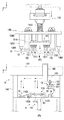
図1は本発明の一実施形態に係る移載システム1を適用した基板処理設備Aの概略図である。基板処理設備Aは、移載システム1と、格納装置2と、処理装置3と、処理装置4とを備える。
<Substrate processing equipment>
FIG. 1 is a schematic view of a substrate processing facility A to which a
格納装置2は、後述するキャリア5を複数格納可能である。キャリア5は基板を保持するための器具である。基板は、例えばFPC(フレキシブルプリント基板)に代表される可撓性を有するフィルム状基板、或いは、可撓性を有する膜体、可撓性を有するシート体、及び可撓性を有する箔体などが挙げられる。格納装置2には、基板Wが保持されたキャリア5又は基板Wを取り出した空のキャリア5を格納可能である。格納装置2は、移載システム1に対するキャリア5の供給と、移載システム1からのキャリア5の回収とを行う装置である。
The storage device 2 can store a plurality of
処理装置3は例えば塗布された半田の加熱処理(リフロー)を行う装置であり、処理装置4は例えば、冷却や洗浄処理を行う装置である。移載システム1は、基板Wを保持するキャリア5を処理装置3から搬入するための搬送装置10を備える。そして、キャリア5から基板Wを取出し、取り出した基板を処理装置4へ搬送する。基板Wが取り出された空のキャリア5は、格納装置2へ搬送する。
The
<移載システム>
図2は移載システム1の概略図である。移載システム1は、搬送装置10と、キャリア処理装置11と、搬送装置12と、保持装置13と、移動装置14と、を備える。搬送装置10、キャリア処理装置11、搬送装置12および移動装置14の支持構造及び配置は、特に限定されないが、本実施形態においては、ベース部を有する架台上に、搬送装置10と、キャリア処理装置11と、搬送装置12と、移動装置14とが配置される。搬送装置10および搬送装置12は、それぞれの搬送方向が平行になるように、かつ、搬送方向と直交する方向に離間させて配置される。また、キャリア処理装置11は、搬送装置10と搬送装置12との間に配置される。移動装置14は、搬送装置10、キャリア処理装置11および搬送装置12の間で保持装置13を移動可能に配置される。
<Transfer system>
FIG. 2 is a schematic diagram of the
搬送装置10は、例えば、搬送方向となるX方向に延びるベルトコンベア機構を備え、不図示のベルト上に載置されたキャリア5を水平姿勢のまま搬送する。同図の例ではキャリア5が搬送装置10上に搭載されている状態を示している。搬送装置10は、処理装置3からのキャリア5の搬入と、格納装置2へのキャリア5の搬出とを行う。処理装置3からのキャリア5には基板Wが保持されている。格納装置2には基板Wを取り出した後の空のキャリア5を搬出する。
The
キャリア5は、基板Wが載置される載置部50と、載置部50の上面に密着して重ねられるカバー51とを備える。載置部50とカバー51とは共に板状の部材であり、本実施形態では方形状をなしている。載置部50とカバー51とは、ここでは、磁力により互いに吸着(連結)する。この場合、例えば、載置部50に永久磁石を設け、カバー51は磁石にくっつく金属材料とすることができる。載置部50とカバー51との密着、連結としては、磁力による吸着の他に、クランプ部材などで物理的に挟むようにしても良い。
The
基板Wは載置部50とカバー51との間に挟まれて保持される。カバー51は、複数の切り欠き51aと、開口部51bと、位置決め用の孔51cとを有する。切り欠き51aは、カバー51の4隅近傍に形成されており、後述するキャリア処理装置11が載置部50を保持する際に、カバー51との干渉を防止するために形成されている。開口部51bは、基板Wとカバー51とが重ならない露出部を形成する。本実施形態の場合、カバー51の中央に開口部51bを形成しているが、開口部51bの部位はどこでもよく、また、開口部51bに代えて切り欠きとしてもよい。更に、カバー51のサイズを基板Wよりも小さくして、カバー51の周縁外方に基板Wが露出するようにしてもよい。孔51cは、カバー51の四隅に設けられた貫通孔である。載置部50の四隅には、孔51cと重なる位置に孔50aが形成されている(図3に図示)。
The substrate W is sandwiched and held between the
搬送装置12は、処理装置4への基板Wの搬出を行う。搬送装置12は、例えば、X方向に延びるベルトコンベア機構を備え、図示しないベルト上に直接載置された基板Wを水平姿勢のまま搬送する。
The
搬送装置10と搬送装置12との間にはキャリア処理装置11が設けられている。図2及び図3を参照してキャリア処理装置11について説明する。図3はキャリア処理装置11の概略図である。キャリア処理装置11は、位置決めユニット110と分離ユニット111とを備える。図3は載置部50が位置決めユニット110に保持された状態を示している。
A
位置決めユニット110は、キャリア5を位置決めして保持するユニットであり、本実施形態の場合、載置部50を把持してその位置決めを行う。位置決めユニット110は、ベース部材1100と、複数の載置ピン1101と、複数のアクチュエータ1102と、複数の位置決め部材1103と、を備える。
The
ベース部材1100は、板状の部材であり、上述した各構成を搭載している。ベース部材1100の中央部には、後述する分離ユニット111のピン支持テーブル1113やピン1114が通過可能な開口部が形成されている。
The
載置ピン1101はベース部材1100上に立設され、先端部が円錐状に形成されたガイド部1101aと載置部50の下面を支持する支持面1101bとが設けられており、本実施形態の場合、2か所設けられている。載置部50の下面には載置ピン1101が遊嵌される孔が形成されており、載置部50はガイドされつつ載置ピン1101上に設けられた支持面に支持され搭載される。
The mounting
アクチュエータ1102は、例えば電動シリンダであり、位置決め部材1103をZ方向に往復移動する。本実施形態の場合、1つの位置決め部材1103に対して1つのアクチュエータ1102が割り当てられている。
The
位置決め部材1103は垂直部および水平部が設けられたL字型をなしており、載置部50の周縁に上部および側部から当接して載置部50の位置決めと載置部50の保持とを行う。本実施形態の場合、載置部50の対向する二辺に対して、それぞれ、2つの位置決め部材1103が割り当てられている。各アクチュエータ1102の駆動により、載置部50は、対向する二辺に位置決め部材1103の垂直部および水平部がそれぞれ当接することによって挟まれるようにして、位置決めされ、かつ、水平姿勢で保持される。
The
分離ユニット111は、載置部50に吸着したカバー51を載置部50から分離するユニットである。分離ユニット111は、駆動ユニット1110と、昇降体1111と、ガイド部1112と、ピン支持テーブル1113と、複数のピン1114とを備える。駆動ユニット1110は、モータ等の駆動源1110aと、駆動源1110aの駆動力を昇降体1111に伝達する伝達機構1110bとを備える。伝達機構1110bは、例えばボールねじ機構であり、駆動源1110aの駆動力により、昇降体1111を昇降する。ガイド部1112は昇降体1111の昇降を案内する。ガイド部1112は、本実施形態の場合、昇降方向となるY方向に延びるレール1112aを備え、このレール1112aに昇降体1111に連結されたスライダ1111aが係合される。
The
ピン支持テーブル1113は昇降体1111に連結されて昇降体1111と共に昇降する板状の部材である。複数のピン1114は支持部側先端が水平面状に形成され、ピン支持テーブル1113に立設されている。載置部50には、ピン1114が挿通可能な貫通孔又は切り欠きが形成されており、ピン支持テーブル1113の昇降にしたがって、ピン1114は、上方の位置に設定された作動位置(図3の位置)と、載置部50の下方の位置に設定された退避位置との間で移動可能になっている。作動位置では、ピン1114は載置部50の上面から突出する。
The pin support table 1113 is a plate-like member that is connected to the
位置決めユニット110に保持されている載置部50から、カバー51を分離する際、ピン1114を退避位置から作動位置に上昇させることでカバー51の下面にピン1114を当接させカバー51を突き上げる。これにより、カバー51が載置部50から分離され、載置部50の上方に持ち上げられる。
When the
図2を参照して移動装置14について説明する。移動装置14は、保持装置13をY方向及びZ方向に移動可能であり、搬送装置10とキャリア処理装置11との間、及び、キャリア処理装置11と搬送装置12との間、で保持装置13を上下方向及び水平方向に移動する。
The moving
移動装置14は、移載方向となるZ方向に離間し、Y方向に延設した一対の支柱140と、一対の支柱140間に架設された案内ユニット141と、案内ユニット141に沿ってZ方向に移動可能に支持された水平移動体141aと、水平移動体141aに設けられた昇降ユニット142と、昇降ユニット142により昇降される昇降体144と、昇降体144に設けられた回動ユニット143とを備える。昇降体144は回動ユニット143を支持する。回動ユニット143は、保持装置13に接続され、保持装置13によって保持された基板Wおよびカバー51の面がXZ面(水平面)と平行な状態で回動させ、保持した基板Wまたはカバー51のXZ面における角度調整をする。案内ユニット141が昇降ユニット142を移動させる機構、及び、昇降ユニット142が昇降体144を昇降させる機構は、公知の機構を採用でき、例えば、モータ等の駆動源と、駆動源の駆動力を伝達する伝達機構(例えば、ベルト伝達機構、ボールネジ機構、ラック−ピニオン機構等)と、から構成することができる。また、案内ユニット141及び昇降ユニット142に、水平移動体141a及び昇降体144の各位置を検出するエンコーダ等のセンサを設けることで、各センサの検出結果に基づいて保持装置13の移動制御を行うことができる。本実施形態においては、保持装置13を直線状に移動する直交移動機構を採用しているが、垂直多関節を有するロボットなど多様な移動機構の先端に保持装置13を装着してもよい。
The moving
次に、図4〜図6を参照して保持装置13について説明する。図4(A)及び(B)は保持装置13の概略図であり、図4(A)は保持装置13の斜視図を、図4(B)は保持装置13の分解斜視図をそれぞれ示している。図5(A)及び(B)はカバー保持ユニット130の概略図である。図6(A)及び(B)は基板保持ユニット131の概略図である。
Next, the holding
保持装置13は、カバー保持ユニット130と、基板保持ユニット131と、これらを支持する支持ユニット132と、を備える。
The holding
カバー保持ユニット130は、キャリア5のカバー51を解除自在に保持するユニットである。カバー保持ユニット130は、ベース部材1300と、吸着部1301と、カバー規定部材1302と、位置決め部材1303とを備える。
The
ベース部材1300は板状の部材であり、後述する支持ユニット132の支持部1323が挿通される開口部1300a(本実施形態では2つを図示)を備える。開口部1300aは、支持部1323に応じて形成されるものであり、その数は1つ又は3つ以上であっても良い。
The
吸着部1301は、カバー51を吸着する。吸着部1301はベース部材1300の下方に突出するようにベース部材1300に支持されており、その先端部に空気を吸引する吸着パッドが設けられている。吸着パッドの吸引孔を介して不図示のポンプによって空気を吸引することで、カバー51を負圧吸引し、保持することができる。吸引を停止し、大気圧解放することでカバー51の保持が解除される。本実施形態の場合、吸着部1301は4つ設けられており、吸着部1301が、カバー51の上面に対して4か所吸着することで、カバー規定部材1302と共にカバー51を水平姿勢で保持する。
The
カバー規定部材1302は、カバー保持ユニット130におけるカバー51の保持位置(保持高さ)を規定する部材であり、カバー51をその姿勢を安定して保持することができる。カバー規定部材1302はベース部材1300の下方に突出するようにベース部材1300に支持されており、その先端部に、水平な位置決め面を有している。カバー51の吸着時、この位置決め面にカバー51の上面が当接し、カバー規定部材1302はカバー51の吸着方向(Y方向)の位置を規定することで、カバー51の水平姿勢を保持する。本実施形態の場合、カバー規定部材1302は4つ設けられており、カバー規定部材1302がカバー51の上面に対して4か所当接することで、その吸着方向の位置を規定する。
The
位置決め部材1303は、キャリア5に対するカバー保持ユニット130の位置決めを行う部材である。位置決め部材1303はベース部材1300の下方に突出するようにベース部材1300に支持されており、その先端部に、ピンを備えている。このピンが、載置部50の孔50a及びカバー51の孔51cに下降時に挿入されて係合することで、位置決め部材1303とキャリア5との水平方向の相対的な位置決めを行うことができる。本実施形態の場合、位置決め部材1303は2つ設けられており、位置決め部材1303が、載置部50に対して2か所(詳細には、対角に2か所)係合することで、相対的な位置を規定する。
The
基板保持ユニット131は、基板Wを解除自在に保持するユニットである。基板保持ユニット131は、ベース部材1310と、吸着部1311と、基板規定部材1312と、を備える。ベース部材1310は板状の部材であり、後述する支持ユニット132の支持部1323が固定される取付孔1310a(本実施形態では2つを図示)が形成されている。
The
吸着部1311は、基板Wを吸着する。吸着部1311はベース部材1310の下方に突出するようにベース部材1310に支持されており、その先端部に空気を吸引するベローズパッドが設けられている。ベローズパッドの吸引孔を介して不図示のポンプによって空気を吸引することで、基板Wを負圧吸引し、保持することができる。吸引を停止し、大気圧解放すると基板Wの保持が解除される。本実施形態の場合、吸着部1311は8つ設けられており、吸着部1311が基板Wの上面に対して8か所吸着することで、基板規定部材1312と共に基板Wを水平姿勢で保持する。吸着部1311は、後述する基板規定部材1312に干渉しない位置に、かつ、基板規定部材1312の近傍に配置される。また、吸着部1311は、各基板規定部材1312を挟み込むように配置され、基板Wの上面を後述する位置決め部1312bに確実に当接させつつ基板Wを保持する。
The
基板規定部材1312は、基板保持ユニット131における基板Wの保持位置を規定する部材である。基板規定部材1312はベース部材1310の下方に突出するようにベース部材1310に支持されており、その先端部に、水平な取付部1312aと、取付部1312aから突出して形成された位置決め部1312bとを有している。取付部1312aは、ベース部材1310に、例えばボルトなどの締結部材で取り付ける際に用いられる。また、位置決め部1312bの下面には、基板Wの吸着時に基板Wの上面の一部が当接し、基板Wの吸着方向(Y方向)の位置を規定する。本実施形態の場合、基板規定部材1312は、ベース部材1310の下側に6つ配置されており、それぞれの位置決め部1312bの下面が同じ水平面(面一)になるように配置される。また、3つ一組で基板規定部材1312を直線状に2列になるように並べて配置し、それぞれの列を形成する位置決め部1312bが直線状になるように配置し、それぞれの列は、ベース部材1310の中心線に対して線対称に配置される。複数の位置決め部1312bを設けたことで、吸着時における基板Wの撓みを防止し、水平姿勢で基板Wを保持することを可能とする。なお、1つの位置決め部1312bであっても、その下面の面積を広くとった場合、基板Wを水平姿勢で保持することができる場合がある。
The
支持ユニット132は、カバー保持ユニット130と基板保持ユニット131を支持し、また、移動装置14の回動ユニット143と接続されるユニットである。
The
支持ユニット132は、ベース部材1320と、支持部1322、1323を備えている。ベース部材1320は板状の部材であり、その上面中央部には回動ユニット143(特にその回転出力部)が接続される接続部材1321が設けられている。接続部材1321には例えば回動ユニット143と締結されるボルト孔等が形成される。
The
支持部1322は、一端側がベース部材1320に、他端側がカバー保持ユニット130のベース部材1300に接続され、カバー保持ユニット130を支持する。本実施形態の場合、支持部1322はX方向に離間して2つ設けられている。本実施形態の場合、カバー保持ユニット130は、キャリア5に近接・離間する方向に変位可能に支持(吊設)される。支持部1322を複数設けているので、カバー保持ユニット130は、キャリア5に近接・離間する方向に変位可能なだけでなく、水平面に対して傾斜可能に支持されている。
本実施形態の場合、支持部1322は、カバー保持ユニット130をフローティング支持するフローティング機構として構成され、カバー保持ユニット130の変位を可能としている。
In the case of the present embodiment, the
詳細には、支持部1322はロッドシリンダとバネとから構成されており、ロッドシリンダのシリンダ部がベース部材1320に固定され、ロッド部がベース部材1300に固定されている。バネはシリンダ部とベース部材1300との間に、ロッド部を囲繞して装填されている。シリンダ部に対するロッド部の進退量だけベース部材1300は、ベース部材1320に対して近接、離間する方向(Y方向)に変位可能となる。この結果、カバー51を保持する際、カバー保持ユニット130は、キャリア5に近接・離間する方向に、支持ユニット132に対して変位することができる。バネはベース部材1300とベース部材1320とが離れる方向にこれらを付勢する。
Specifically, the
支持部1323は、一端側がベース部材1320に、他端側がベース部材1300に形成した開口部1300aを通過して、ベース部材1310に接続され、基板保持ユニット131を支持(吊設)する。本実施形態の場合、支持部1323はX方向に離間して2つ設けられている。支持部1323は、支柱状の部材であり、その先端部にベース部材1310が固定される。カバー保持ユニット130と異なり、基板保持ユニット131は、支持ユニット132に対して変位不能に支持される。ベース部材1310及び1320は共に水平姿勢に維持され、ベース部材1300は支持部1322の伸縮により多少の傾斜はあるものの、基本的には水平姿勢に維持される。
The
<制御ユニット>
図7は移載システム1の制御ユニット6のブロック図である。制御ユニット6は移載システム1全体の制御を行う。
<Control unit>
FIG. 7 is a block diagram of the
制御ユニット6は、CPU等の処理部61と、RAM、ROM等の記憶部62と、外部デバイスと処理部61とをインターフェースするインターフェース部63と、を含む。インターフェース部63には、I/Oインターフェースの他、ホストコンピュータとの通信を行う通信インターフェースも含まれる。ホストコンピュータは、例えば、基板処理設備A全体を制御するコンピュータである。
The
処理部61は記憶部62に記憶されたプログラムを実行し、各種のセンサ65の検出結果や、各種のアクチュエータ64を制御する。各種のセンサ65には、例えば、昇降体144の位置を検出するセンサ等が含まれる。各種アクチュエータ64には、例えば、搬送装置10、キャリア処理装置11、搬送装置12、及び、移動装置14の各駆動源や、保持装置13における負圧吸引を行うポンプや制御弁等が含まれる。
The
<制御例>
移載システム1の制御例について図8(A)〜図13(B)を参照して説明する。ここでは、基板Wの移載動作について説明する。具体的には、搬送装置10上に搬入された基板Wを保持するキャリア5から基板Wを取りだし、その基板Wを移載先へ移載する例について説明する。この例では基板Wの移載先は搬送装置12である。
<Control example>
A control example of the
図8(A)は、処理装置3から供給された、基板Wを保持するキャリア5が搬送装置10上の所定位置に搬入された状態を示す。まず、同図に示すように移動装置14によって保持装置13をキャリア5の上方に移動すると共に、回動ユニット143によって保持装置13の水平面における回転角度が調節される。続いて、図8(B)に示すように、移動装置14によって保持装置13を降下し、保持装置13によりキャリア5を保持する。このとき、まず、保持装置13の降下の過程でカバー保持ユニット130の位置決め部材1303が載置部50の孔50a及びカバー51の孔51cに挿入されて係合する。これにより、保持装置13とキャリア5との水平方向の位置決めがなされる。続いてカバー保持ユニット130の吸着部1301の吸引を開始し、カバー51を吸着保持する。このとき、カバー規定部材1302によって、保持位置が規定される。カバー51と載置部50とは磁力により連結しているので、カバー51を吸着保持することで、基板Wを含むキャリア5全体が保持装置13に保持されることになる。
FIG. 8A shows a state where the
次に、図9(A)に示すように、キャリア5を保持した保持装置13を、移動装置14によってキャリア処理装置11上に移動すると共に、回動ユニット143によって保持装置13の水平面における回転角度が調節される。続いて図9(B)に示すように、保持装置13を移動装置14により降下し、キャリア5を位置決めユニット110の載置ピン1101上に載置する。更に、アクチュエータ1102を駆動して位置決め部材1103を載置部50に当接し、載置部50を位置決めして保持する。カバー51には、切り欠き51aが形成されているため、位置決め部材1103が載置部50に当接する際、カバー51と位置決め部材1103とが干渉することがない。
Next, as shown in FIG. 9A, the holding
次に、図10(A)に示すように、分離ユニット111の駆動ユニット1110を駆動して、ピン支持テーブル1113を上昇する。これにより、図10(B)に示すようにピン1114が載置部50から突出してカバー51を突き上げ、載置部50からカバー51を上方に分離させる。すなわち、載置部50とカバー51との連結が解除され、載置部50からカバー51が所定の距離だけ離間した位置に位置づけられる。カバー保持ユニット130は、支持部1322により支持ユニット132に対して変位可能に支持されているため、カバー51が突き上げられる際、カバー保持ユニット130もカバー51と共に上昇することになる。
Next, as shown in FIG. 10A, the
続いて基板保持ユニット131の吸着部1311の吸引を開始する。カバー51には、開口部51bが形成されているため、開口部51bを介して、基板Wのうち、カバー51と重ならない部分が吸着部1311に吸着保持される。このとき、基板規定部材1312により基板Wの位置が規定される。そして、カバー51はカバー保持ユニット130に吸着保持され、基板Wは基板保持ユニット131に吸着保持された状態となる。なお、本実施形態においては、カバー51と載置部50との連結を解除した後に基板Wの吸着を開始しているが、カバー51と載置部50との連結の解除前に基板Wの吸着を開始してもよい。
Subsequently, suction of the
次に、図11(A)に示すように、保持装置13を、移動装置14によって上昇させる。この時、載置部50はキャリア処理装置11上に残留し、カバー51と基板Wとが保持装置13と共に上昇する。カバー51と基板Wとは共に水平姿勢で互いに平行に保持される。
Next, as illustrated in FIG. 11A, the holding
カバー51に対するピン1114の突き上げにより、支持ユニット132に対して上方に変位していたカバー保持ユニット130は、その変位分だけ元の位置に戻る(降下する)。
The push-
次に、図11(B)に示すように、カバー51と基板Wを保持した保持装置13を、移動装置14によって搬送装置12上に移動すると共に、回動ユニット143によって保持装置13の水平面における回転角度が調節される。続いて図12に示すように、保持装置13を搬送装置12上に降下する。
Next, as shown in FIG. 11B, the holding
搬送装置12の上部には、図13(A)に示すように、基板Wと干渉しない位置に突起部120が形成されている。保持装置13を搬送装置12上に降下する際、この突起部120はカバー51に当接し、カバー51の降下を基板Wよりも先に停止させる。すなわち、カバー51の下面に突起部120が当接すると、カバー保持ユニット130は、それ以上降下できなくなる。カバー保持ユニット130は、支持部1322により支持ユニット132に対して変位可能に支持されているため、保持装置13の降下を継続すると、基板保持ユニット131はカバー保持ユニット130よりも降下して、カバー51から基板Wが離れる状態となる。
As shown in FIG. 13A, a
保持装置13の降下を所定位置で停止し、吸着部1311の吸引を停止して大気開放することで基板Wの吸着が解除され、搬送装置12上に載置される。以上により、基板Wの搬送装置12への移載が完了する。
The lowering of the holding
その後、カバー51を、移載元の位置決めユニット110上の載置部50に重ねて空のキャリア5とし、この空のキャリア5を搬送装置10に移載する動作を行う。まず、カバー51のみを保持した保持装置13を図13(B)に示すように、キャリア処理装置11上に移動させると共に、回動ユニット143によって保持装置13の水平面における回転角度を調節し、移載元の載置部50に移動させ、カバー51と載置部50とを連結させる。なお、ピン支持テーブル1113は、分離動作と逆動作で動作させて、ピン1114を退避位置に移動させる。
Thereafter, the
カバー51を載置部50に重ねることで、両者が磁力により連結する。これにより基板Wを保持していない、空のキャリア5となる。アクチュエータ1102を駆動して位置決め部材1103を載置部50から離間し、載置部50の保持を解除する。
By overlapping the
空のキャリア5を保持した保持装置13を移動装置14により搬送装置10上に移動すると共に、回動ユニット143によって保持装置13の水平面における回転角度が調節される。続いて、カバー保持ユニット130の吸着部1301の吸引を停止して大気開放する。これにより空のキャリア5の保持が解除され、空のキャリア5は搬送装置10に移載される。空のキャリア5は搬送装置10によって格納装置2へ搬出され、基板Wを保持している新たなキャリア5が処理装置3から搬送装置10に搬入されることになる。
The holding
また、搬送装置12上に載置された基板Wは、搬送装置12により処理装置4へ移送され、処理装置4によって処理が行われる。
The substrate W placed on the
以上の通り、本実施形態では、キャリア処理ユニット11から搬送装置12へ基板Wを移載する際、カバー51と基板Wとの双方を保持装置13で保持して搬送するので、カバー51と基板Wとを別々に移動する方式に比べて移載の工程数を減らすことができ、基板Wの移載効率を向上することができる。カバー51と基板Wとは、それぞれの面同士が互いに平行な姿勢で隣接して保持され、キャリア5におけるこれらの位置関係を保ったまま移動される。このため、カバー51の持ち替え等が不要となり、基板Wの移載効率の向上に加えて、カバー51を載置部50上に戻す際の効率も向上できる。
As described above, in the present embodiment, when the substrate W is transferred from the
<第2実施形態>
第1実施形態では、基板保持ユニット131の吸着部1311による負圧吸引により、基板Wと接触吸着して基板Wを保持したが、ベルヌーイチャック方式による非接触吸着としてもよい。
Second Embodiment
In the first embodiment, the substrate W is held by contact suction with the substrate W by negative pressure suction by the
図14は本実施形態の保持装置13の一部分解図、図15(A)及び(B)は基板保持ユニット133の概略図である。保持装置13は、カバー保持ユニット130と、基板保持ユニット133と、これらを支持する支持ユニット132と、を備える。カバー保持ユニット130と支持ユニット132の構成は第1実施形態と同じである。
FIG. 14 is a partially exploded view of the holding
基板保持ユニット133は、基板Wを解除自在に保持するユニットである。基板保持ユニット133は、ベース部材1330と、吸着部1331と、規制ユニット1332と、を備える。ベース部材1330には、支持ユニット132の支持部1323が固定される取付孔1330a(本実施形態では2つを図示)が形成されている。また、ベース部材1330は、位置決めユニット110の位置決め部材1103との干渉を回避するように形成されている。
The
吸着部1331は、ベース部材1330の下面の凹部に設けられている。本実施形態では、基板の長手方向に間隔を空けて3つの吸着部が設けられている。吸着部1331はベース部材1330の内部に設けられた通路を介して不図示の流体発生減に接続され空気を噴出するように構成されている。吸着部1331から噴出される空気はベース部材1330の下面と基板Wとの隙間から外部周囲に流れ、吸着部1331と基板Wとの隙間の気圧が大気圧よりも低くなることで基板Wが非接触で吸着される。
The
基板Wの吸着は非接触吸着であり、基板Wはその基板面方向へ自由移動可能である。そこで、基板Wの基板面方向(本実施形態では水平方向)への自由移動を規制する規制ユニット1332がベース部材1330の長手方向のそれぞれの端部に設けられた吸着部1331の周辺に複数設けられている。規制ユニット1332は、ベース部材1330の下面から突出するピン状の規制部1332aを備えている。規制部1332aは、規制ユニット1332の本体に対して進退可能に設けられている。このため、ベース部材1330の下面からY方向に伸縮自在に突出する。
The adsorption of the substrate W is non-contact adsorption, and the substrate W can freely move in the direction of the substrate surface. Therefore, a plurality of
複数の規制ユニット1332は、規制部1332aが基板Wの外縁を囲むように間隔を空けて配置されており、本実施形態の場合、6つ配置されている。詳細には、基板Wの長手方向の対向するそれぞれの辺に2つずつ合計4つの規制ユニット1332および、基板Wの短手方向の対向するそれぞれの辺に1つずつ合計2つの規制ユニット1332がそれぞれ配置され、基板Wが基板面方向に移動する際、基板Wの外縁がそれぞれの規制部1332aに当接するので、その自由移動が規制される。
The plurality of restricting
次に、本実施形態における基板Wの移載動作中の基板保持ユニット133の動作について図16(A)〜図18を参照して説明する。
Next, the operation of the
図16(A)は、ピン1114によりカバー51を突き上げた状態を示し、第1実施形態の図10(A)の段階に相当する。このとき、基板保持ユニット133の規制部1332aは載置部50の上面に当接した状態にあり、基板Wの周囲は6つの規制部1332aで囲まれている。また、基板Wとカバー51とは、離間した状態となる。なお、保持装置13を位置決めユニット110上に降下する際、規制部1332aは伸縮自在であるため、規制部1332aが載置部50の上面に当接した後、更に、保持装置13を降下すると規制部1332aが収縮することになる。
FIG. 16A shows a state in which the
吸着部1331から空気の噴出を開始すると、図16(B)に示すように基板Wが載置部50から離間し、ベース部材1330の下面に非接触で吸着される。規制部1332aは、非接触で吸着される際に基板Wの周囲を規制しつつ載置部50から非接触吸着保持位置までの基板Wの移動をガイドする。なお、カバー51と基板Wとの対向する面は、重なる部分においては、接触した状態で保持装置13に保持される。続いて、移動装置14により保持装置13を上昇する。カバー51と基板Wとは共に水平姿勢で互いに平行に保持される。
When the ejection of air from the
次に、図17(A)に示すように、移動装置14により保持装置13を搬送装置12上に降下する。移動の際、基板Wがその基板面方向(Z方向)に自由移動する場合があるが、これは規制部1332aにより規制される。
Next, as illustrated in FIG. 17A, the holding
第1実施形態と同様に、保持装置13を搬送装置12上に降下する際、突起部120がカバー51に当接して、図17(B)の状態となる。吸着部1331の空気の噴出を停止すると、基板Wの吸着が解除され、搬送装置12上に基板Wが載置される。この際も規制部1332aは、基板Wの周囲を規制しつつ搬送装置12状に載置されるまで基板Wの移動をガイドする。以上により、基板Wの搬送装置12への移載が完了する。
As in the first embodiment, when the holding
その後、図18に示すように、第1実施形態と同様にカバー51を、移載元の位置決めユニット110上の載置部50に重ねて空のキャリア5とし、この空のキャリア5を搬送装置10に搬送する動作を行うことになる。
Then, as shown in FIG. 18, the
本実施形態の場合、基板Wが基板保持ユニット133と非接触で保持されるので、基板Wに吸着痕がつくことを防止できる。
In the case of this embodiment, since the substrate W is held in a non-contact manner with the
なお、本移載システム1においては、搬送装置10と、キャリア処理装置11とがZ方向に異なる位置に配置されているが、搬送装置10による搬送軌道途中にキャリア処理装置11を配置させて、Z方向で同じ位置に配置させてもよい。これにより、キャリア5の搬入出および載置部50とカバー51との分離および基板Wとカバー51との保持を連続して行うことが可能となる。
In addition, in this
Claims (10)
前記保持装置は、
前記カバーを保持するカバー保持ユニットと、
前記基板を保持する基板保持ユニットと、
前記カバー保持ユニット及び前記基板保持ユニットを支持する支持ユニットと、を備え、
前記支持ユニットは、前記キャリアに近接・離間する方向に、前記カバー保持ユニットが変位可能に前記カバー保持ユニットを支持し、
前記移載方法は、
前記カバーを前記載置部から突き上げて前記載置部から前記カバーを分離する工程と、
前記載置部上の前記基板及び前記カバーを前記保持装置によって保持する工程であって、前記カバーと前記基板とが平行な姿勢で、前記カバーを前記カバー保持ユニットにより、前記基板を前記基板保持ユニットにより、それぞれ保持する保持工程と、
前記保持装置を移動することにより、前記基板及び前記カバーを前記載置部から移載先に移動する移動工程と、
前記移動工程により前記移載先に移動された前記基板及び前記カバーの内、前記基板の保持を解除して移載先に前記基板を載置する基板載置工程と、
前記カバーのみを保持する前記保持装置を、移載元の前記載置部に移動させる工程と、
移載元の前記載置部上面に前記カバーを重ねる工程と、を含み、
前記基板載置工程は、前記保持装置を降下させる一方、前記カバー保持ユニットの降下を規制して前記カバーの降下を前記基板よりも先に停止させ、前記カバーと前記基板とを離間させる工程を含む、
ことを特徴とする移載方法。 The substrate held between the mounting unit and the cover is transferred by a holding device from a carrier including a mounting unit on which the substrate is mounted and a cover that is in close contact with the upper surface of the mounting unit. A transfer method,
The holding device is
A cover holding unit for holding the cover;
A substrate holding unit for holding the substrate;
A support unit for supporting the cover holding unit and the substrate holding unit,
The support unit supports the cover holding unit so that the cover holding unit can be displaced in a direction approaching / separating from the carrier,
The transfer method is:
Pushing up the cover from the mounting portion and separating the cover from the mounting portion;
The step of holding the substrate and the cover on the placement unit by the holding device , wherein the cover and the substrate are held in a parallel posture, and the cover is held by the cover holding unit and the substrate is held by the substrate A holding process for holding each unit ,
A moving step of moving the substrate and the cover from the placement unit to the transfer destination by moving the holding device;
Of the substrate moved to the transfer destination by the moving step and the cover, a substrate placing step of releasing the holding of the substrate and placing the substrate on the transfer destination;
A step of moving the holding device that holds only the cover to the placement portion of the transfer source; and
And a step of overlapping the cover on the placement unit upper surface of the transfer source ,
The substrate placing step includes a step of lowering the holding device, restricting the lowering of the cover holding unit, stopping the lowering of the cover before the substrate, and separating the cover and the substrate. Including,
A transfer method characterized by that.
前記保持工程において、
前記カバー保持ユニットは、前記カバーを吸着し、
前記基板保持ユニットは、前記基板を吸着すると共に、規定部材により基板の位置決めを行う、
ことを特徴とする移載方法。 The transfer method according to claim 1,
In the holding step,
The cover holding unit adsorbs the cover;
The substrate holding unit adsorbs the substrate and positions the substrate by a defining member.
A transfer method characterized by that.
前記保持工程において、
前記カバー保持ユニットは、前記カバーを吸着し、
前記基板保持ユニットは、前記基板を非接触吸着すると共に、非接触吸着された前記基板の基板面方向への自由移動を規制する、
ことを特徴とする移載方法。 The transfer method according to claim 1,
In the holding step,
The cover holding unit adsorbs the cover;
The substrate holding unit adsorbs the substrate in a non-contact manner and regulates free movement of the substrate adsorbed in a non-contact manner in the substrate surface direction.
A transfer method characterized by that.
移載元の前記載置部と前記載置部に重ねられた前記カバーを搬出し、新たな前記キャリアを搬入する搬入出工程と、を更に含む、
ことを特徴とする移載方法。 The transfer method according to claim 1 ,
A loading / unloading step of unloading the cover placed on the loading unit and the loading unit and loading the new carrier;
A transfer method characterized by that.
前記カバーを保持するカバー保持ユニットと、
前記基板を保持する基板保持ユニットと、
前記カバー保持ユニット及び前記基板保持ユニットを支持する支持ユニットと、を備え、
前記カバーと前記基板とが平行な姿勢で、前記カバーが前記カバー保持ユニットにより、前記基板が前記基板保持ユニットにより、それぞれ保持され、
前記支持ユニットは、
前記カバー保持ユニットを前記キャリアに近接・離間する方向にフローティング支持するフローティング機構を備える一方、前記基板保持ユニットを変位不能に支持する、
ことを特徴とする保持装置。 From the carrier provided with a placement part on which the substrate is placed and a cover that is closely stacked on the placement part upper surface, the substrate and the cover held between the placement part and the cover. A holding device for holding,
A cover holding unit for holding the cover;
A substrate holding unit for holding the substrate;
A support unit for supporting the cover holding unit and the substrate holding unit,
The cover and the substrate are held in a parallel posture, the cover is held by the cover holding unit, and the substrate is held by the substrate holding unit, respectively.
The support unit is
While having a floating mechanism for floatingly supporting the cover holding unit in the direction of approaching and separating from the carrier, the substrate holding unit is supported so as not to be displaced .
A holding device.
前記カバー保持ユニットは、
前記カバーを吸着する吸着部と、
前記カバーに当接して前記カバーの吸着方向の位置を規定するカバー規定部材と、を備える、
ことを特徴とする保持装置。 The holding device according to claim 5 ,
The cover holding unit is
An adsorbing part for adsorbing the cover;
A cover defining member that abuts against the cover and defines a position in the suction direction of the cover;
A holding device.
前記カバー保持ユニットは、
前記カバーを吸着する吸着部と、
前記載置部と係合して前記キャリアに対して前記カバー保持ユニットを位置決めする位置決め部材と、を備える、
ことを特徴とする保持装置。 The holding device according to claim 5 ,
The cover holding unit is
An adsorbing part for adsorbing the cover;
A positioning member that engages with the mounting portion and positions the cover holding unit with respect to the carrier,
A holding device.
前記基板保持ユニットは、
前記基板を非接触吸着する吸着部と、
非接触吸着された前記基板の基板面方向への自由移動を規制する規制ユニットと、を備える、
ことを特徴とする保持装置。 The holding device according to claim 5 ,
The substrate holding unit is
An adsorbing part for non-contact adsorbing the substrate;
A regulation unit that regulates free movement of the substrate that is non-contact-adsorbed in the substrate surface direction,
A holding device.
前記支持ユニットは、前記基板保持ユニットを支持する支持部を備え、
前記規制ユニットは、前記基板面方向と直交する方向に伸縮自在に突出する規制部を備える、
ことを特徴とする保持装置。 The holding device according to claim 8 , wherein
The support unit includes a support portion that supports the substrate holding unit,
The restricting unit includes a restricting portion that protrudes and contracts in a direction orthogonal to the substrate surface direction.
A holding device.
前記キャリアを位置決めして保持する位置決めユニットと、
前記位置決めユニットに保持されている前記キャリアの前記載置部から、前記カバーを分離する分離ユニットと、
請求項5〜9のいずれか1項記載の保持装置と、
前記保持装置を移動する移動装置と、
を備える、
ことを特徴とする移載システム。 Transferring the substrate held between the mounting unit and the cover from a carrier including a mounting unit on which the substrate is mounted and a cover that is in close contact with the upper surface of the mounting unit. System,
A positioning unit for positioning and holding the carrier;
A separation unit that separates the cover from the mounting portion of the carrier held by the positioning unit;
The holding device according to any one of claims 5 to 9 ,
A moving device for moving the holding device;
Comprising
A transfer system characterized by that.
Priority Applications (5)
| Application Number | Priority Date | Filing Date | Title |
|---|---|---|---|
| JP2014003675A JP6383152B2 (en) | 2014-01-10 | 2014-01-10 | Transfer method, holding device and transfer system |
| TW103143310A TWI542266B (en) | 2014-01-10 | 2014-12-11 | Transfer method, holding device and transfer system |
| US14/571,448 US9394128B2 (en) | 2014-01-10 | 2014-12-16 | Transfer method, holding apparatus, and transfer system |
| KR1020140193648A KR101633689B1 (en) | 2014-01-10 | 2014-12-30 | Transfer method, holding apparatus, and transfer system |
| CN201510010275.8A CN104780750B (en) | 2014-01-10 | 2015-01-09 | Method for shifting, holding meanss and carrying system |
Applications Claiming Priority (1)
| Application Number | Priority Date | Filing Date | Title |
|---|---|---|---|
| JP2014003675A JP6383152B2 (en) | 2014-01-10 | 2014-01-10 | Transfer method, holding device and transfer system |
Publications (3)
| Publication Number | Publication Date |
|---|---|
| JP2015133391A JP2015133391A (en) | 2015-07-23 |
| JP2015133391A5 JP2015133391A5 (en) | 2017-01-12 |
| JP6383152B2 true JP6383152B2 (en) | 2018-08-29 |
Family
ID=53520736
Family Applications (1)
| Application Number | Title | Priority Date | Filing Date |
|---|---|---|---|
| JP2014003675A Active JP6383152B2 (en) | 2014-01-10 | 2014-01-10 | Transfer method, holding device and transfer system |
Country Status (5)
| Country | Link |
|---|---|
| US (1) | US9394128B2 (en) |
| JP (1) | JP6383152B2 (en) |
| KR (1) | KR101633689B1 (en) |
| CN (1) | CN104780750B (en) |
| TW (1) | TWI542266B (en) |
Families Citing this family (12)
| Publication number | Priority date | Publication date | Assignee | Title |
|---|---|---|---|---|
| US10070567B2 (en) * | 2016-06-13 | 2018-09-04 | Arris Enterprises Llc | System for printed circuit board unlocking and automated reflow carrier recycling |
| DE102016011618A1 (en) * | 2016-09-28 | 2018-03-29 | Broetje-Automation Gmbh | end effector |
| CN107160384A (en) * | 2016-09-30 | 2017-09-15 | 江苏中天华宇智能科技有限公司 | A kind of powder or the packed class material lifting reclaimer system of graininess |
| JP6783614B2 (en) * | 2016-10-11 | 2020-11-11 | 株式会社ディスコ | Wiring board manufacturing method |
| CN106584435A (en) * | 2016-12-29 | 2017-04-26 | 安徽智森电子科技有限公司 | Automatic feeding manipulator mechanism |
| CN107150350B (en) * | 2017-05-25 | 2019-07-12 | 东莞质研工业设计服务有限公司 | Sucker mounting plate equipped with barrier wall |
| CN109079831B (en) * | 2018-09-30 | 2024-04-12 | 中建材凯盛机器人(上海)有限公司 | Floating reset handle |
| JP7075498B2 (en) * | 2018-10-02 | 2022-05-25 | 株式会社Fuji | Working machine |
| US20220322588A1 (en) * | 2019-10-02 | 2022-10-06 | Fuji Corporation | Substrate support pin installation jig, and method for installing substrate support pin |
| CN111295091B (en) * | 2020-03-17 | 2021-07-13 | 鸿富锦精密电子(成都)有限公司 | Pressure head device and method for positioning flexible circuit board |
| CN114394415B (en) * | 2021-12-28 | 2023-12-12 | 赤壁市万皇智能设备有限公司 | FPC automated production line based on AGV automatic handling system |
| CN117049125B (en) * | 2023-10-11 | 2023-12-26 | 合肥铠柏科技有限公司 | Sample conveyer capable of self-adapting to angle error of sample rack |
Family Cites Families (26)
| Publication number | Priority date | Publication date | Assignee | Title |
|---|---|---|---|---|
| JPS5920638U (en) * | 1982-07-29 | 1984-02-08 | 日本電気ホームエレクトロニクス株式会社 | positioning device |
| US6544379B2 (en) * | 1993-09-16 | 2003-04-08 | Hitachi, Ltd. | Method of holding substrate and substrate holding system |
| JP3695611B2 (en) * | 1996-07-02 | 2005-09-14 | ソニー株式会社 | Transfer and transfer device and transfer and transfer method |
| US5893795A (en) * | 1997-07-11 | 1999-04-13 | Applied Materials, Inc. | Apparatus for moving a cassette |
| JP4082770B2 (en) * | 1998-02-02 | 2008-04-30 | 富士機械製造株式会社 | Electric component conveying apparatus and holder replacement method and apparatus therefor |
| JP2000210887A (en) * | 1999-01-26 | 2000-08-02 | Kubota Corp | Robot hand device |
| JP2001244279A (en) * | 2000-02-25 | 2001-09-07 | Nec Niigata Ltd | Method and apparatus for feed of board as well as chip feeder and chip mounting machine |
| JP3825628B2 (en) * | 2000-12-28 | 2006-09-27 | 太陽誘電株式会社 | Flexible circuit board holder and flexible circuit board holding method using the same. |
| JP2002299406A (en) * | 2001-03-29 | 2002-10-11 | Dainippon Screen Mfg Co Ltd | Substrate transportation and substrate processor using the same |
| CN100367473C (en) * | 2001-09-03 | 2008-02-06 | 东京毅力科创株式会社 | Substrate treating device and substrate treating method |
| JP4313031B2 (en) * | 2002-12-13 | 2009-08-12 | パナソニック株式会社 | Tool changer and tool |
| JP4616731B2 (en) * | 2005-09-01 | 2011-01-19 | 東京エレクトロン株式会社 | Coating and developing equipment |
| WO2007080779A1 (en) * | 2006-01-12 | 2007-07-19 | Nikon Corporation | Object conveyance apparatus, exposure apparatus, object temperature regulation apparatus, object conveyance method, and method of producing microdevice |
| JP2008021730A (en) | 2006-07-11 | 2008-01-31 | Nikon Corp | Reticle cover, reticle conveyance method, and projection exposure method |
| JP5043793B2 (en) * | 2008-09-30 | 2012-10-10 | アズビル株式会社 | Automatic mounting device |
| JP5563318B2 (en) * | 2009-03-02 | 2014-07-30 | キヤノンアネルバ株式会社 | Substrate support apparatus, substrate processing apparatus, substrate support method, substrate support apparatus control program, and recording medium |
| DE102009013778B4 (en) * | 2009-03-18 | 2013-08-14 | Quantifoil Instruments Gmbh | Positioning device for a sample carrier |
| US8970820B2 (en) * | 2009-05-20 | 2015-03-03 | Nikon Corporation | Object exchange method, exposure method, carrier system, exposure apparatus, and device manufacturing method |
| JP5244701B2 (en) * | 2009-05-20 | 2013-07-24 | 株式会社 大昌電子 | Substrate holding and conveying jig, substrate pressing member, pressing member removing jig, metal mask plate, printed wiring board conveying method, wiring board manufacturing method with electronic components, and substrate conveying apparatus |
| JP5403247B2 (en) * | 2009-09-07 | 2014-01-29 | 村田機械株式会社 | Substrate transfer device |
| KR101528137B1 (en) * | 2009-09-16 | 2015-06-11 | 주식회사 원익아이피에스 | Substrate exchanging module for substrate processing apparatus, and substrate processing apparatus having the same |
| JP2011245595A (en) * | 2010-05-27 | 2011-12-08 | Sharp Corp | Transfer hand, and transfer method |
| JP2012174822A (en) * | 2011-02-21 | 2012-09-10 | Juki Corp | Compression control head of mounter device |
| JP5875950B2 (en) * | 2012-06-29 | 2016-03-02 | 株式会社荏原製作所 | Substrate holding device and polishing device |
| JP2015123571A (en) * | 2013-12-27 | 2015-07-06 | ビアメカニクス株式会社 | Substrate sucking and conveying mechanism |
| TWI589396B (en) * | 2014-03-27 | 2017-07-01 | 荏原製作所股份有限公司 | Elastic membrane, substrate holding apparatus, and polishing apparatus |
-
2014
- 2014-01-10 JP JP2014003675A patent/JP6383152B2/en active Active
- 2014-12-11 TW TW103143310A patent/TWI542266B/en active
- 2014-12-16 US US14/571,448 patent/US9394128B2/en active Active
- 2014-12-30 KR KR1020140193648A patent/KR101633689B1/en active IP Right Grant
-
2015
- 2015-01-09 CN CN201510010275.8A patent/CN104780750B/en active Active
Also Published As
| Publication number | Publication date |
|---|---|
| JP2015133391A (en) | 2015-07-23 |
| US20150197405A1 (en) | 2015-07-16 |
| KR20150083780A (en) | 2015-07-20 |
| TWI542266B (en) | 2016-07-11 |
| TW201529454A (en) | 2015-08-01 |
| US9394128B2 (en) | 2016-07-19 |
| CN104780750B (en) | 2017-09-26 |
| KR101633689B1 (en) | 2016-06-27 |
| CN104780750A (en) | 2015-07-15 |
Similar Documents
| Publication | Publication Date | Title |
|---|---|---|
| JP6383152B2 (en) | Transfer method, holding device and transfer system | |
| KR102495699B1 (en) | Apparatus for manufacturing semiconductor and method of manufacturing semiconductor device | |
| KR101489094B1 (en) | Detaching apparatus and detaching method | |
| KR101541643B1 (en) | Detaching apparatus | |
| US10655658B2 (en) | Material handling system | |
| JP6280817B2 (en) | Component mounting device | |
| JP2007158102A (en) | Bonding equipment | |
| JP5877761B2 (en) | Holding device, transport system, and holding method | |
| KR102635493B1 (en) | Apparatus for transferring die in bonding equipment and method thereof | |
| CN103094168B (en) | Pickup in packaging technology and place tool | |
| JP2013154968A (en) | Holding device and holding method | |
| JP2012114315A (en) | Work transfer apparatus | |
| KR102122042B1 (en) | Chip bonder and apparatus for processing a substrate having the same | |
| JP2017059777A (en) | Conveyance device and solder ball print system | |
| JP6019406B2 (en) | Electronic component mounting apparatus and electronic component mounting method | |
| JP6718693B2 (en) | Equipment with backup jig | |
| JP5827046B2 (en) | Plate member support device and support method, and plate member transport device | |
| WO2018131139A1 (en) | Component mounting device | |
| JP4585496B2 (en) | Semiconductor chip mounting equipment | |
| JP2014172047A (en) | Workpiece conveyance method and workpiece conveyance system | |
| KR20140137075A (en) | Apparatus for mounting additional plate to fpc | |
| CN112789959B (en) | Working machine | |
| CN114208411B (en) | Work machine and component conveying method | |
| JP5447399B2 (en) | Substrate supply device | |
| JP5885801B2 (en) | Backup pin device, backup pin placement method and placement device |
Legal Events
| Date | Code | Title | Description |
|---|---|---|---|
| A521 | Written amendment |
Free format text: JAPANESE INTERMEDIATE CODE: A523 Effective date: 20161121 |
|
| A621 | Written request for application examination |
Free format text: JAPANESE INTERMEDIATE CODE: A621 Effective date: 20161121 |
|
| A977 | Report on retrieval |
Free format text: JAPANESE INTERMEDIATE CODE: A971007 Effective date: 20170822 |
|
| A131 | Notification of reasons for refusal |
Free format text: JAPANESE INTERMEDIATE CODE: A131 Effective date: 20170901 |
|
| A521 | Written amendment |
Free format text: JAPANESE INTERMEDIATE CODE: A523 Effective date: 20171013 |
|
| A131 | Notification of reasons for refusal |
Free format text: JAPANESE INTERMEDIATE CODE: A131 Effective date: 20180416 |
|
| A521 | Written amendment |
Free format text: JAPANESE INTERMEDIATE CODE: A523 Effective date: 20180614 |
|
| TRDD | Decision of grant or rejection written | ||
| A01 | Written decision to grant a patent or to grant a registration (utility model) |
Free format text: JAPANESE INTERMEDIATE CODE: A01 Effective date: 20180706 |
|
| A61 | First payment of annual fees (during grant procedure) |
Free format text: JAPANESE INTERMEDIATE CODE: A61 Effective date: 20180803 |
|
| R150 | Certificate of patent or registration of utility model |
Ref document number: 6383152 Country of ref document: JP Free format text: JAPANESE INTERMEDIATE CODE: R150 |
|
| R250 | Receipt of annual fees |
Free format text: JAPANESE INTERMEDIATE CODE: R250 |