JP6374189B2 - Die bonder and bonding method - Google Patents
Die bonder and bonding method Download PDFInfo
- Publication number
- JP6374189B2 JP6374189B2 JP2014053699A JP2014053699A JP6374189B2 JP 6374189 B2 JP6374189 B2 JP 6374189B2 JP 2014053699 A JP2014053699 A JP 2014053699A JP 2014053699 A JP2014053699 A JP 2014053699A JP 6374189 B2 JP6374189 B2 JP 6374189B2
- Authority
- JP
- Japan
- Prior art keywords
- die
- driven body
- bonding
- processing operation
- vibration
- Prior art date
- Legal status (The legal status is an assumption and is not a legal conclusion. Google has not performed a legal analysis and makes no representation as to the accuracy of the status listed.)
- Active
Links
Images


Description
本発明は、ダイボンダ及びボンディング方法に係わり、処理時間を短縮できるスループットの高いダイボンダ及びボンディング方法に関する。 The present invention relates to a die bonder and a bonding method, and more particularly to a die bonder and a bonding method with high throughput that can reduce processing time.
半導体製造装置の一つに半導体チップ(ダイ)をリードフレームなどの基板にボンディングするダイボンダがある。ダイボンダでは、ボンディングヘッドでダイを真空吸着し、高速で上昇し、水平移動し、下降して基板に実装する。 One type of semiconductor manufacturing apparatus is a die bonder that bonds a semiconductor chip (die) to a substrate such as a lead frame. In the die bonder, the die is vacuum-adsorbed by a bonding head, and the die is raised at a high speed, horizontally moved, and lowered to be mounted on a substrate.
例えば、ボンディングヘッドでダイを実装する場合、ダイサイズの微小化に伴い、実装精度が厳しくなってきている。そのために、従来は、ボンディングヘッドによるダイの実装(ボンディング)工程により生じる振動によりダイの実装精度が低下することを防ぐため、ボンディングヘッドの振動の減衰時間を考慮して時間的余裕をもって評価し、ダイの実装を行っていた。 For example, when a die is mounted with a bonding head, the mounting accuracy is becoming stricter as the die size is reduced. Therefore, conventionally, in order to prevent the mounting accuracy of the die from being lowered due to vibration caused by the die mounting (bonding) process by the bonding head, evaluation is performed with a time margin in consideration of the damping time of the bonding head vibration, Die was mounted.
このような、ダイボンダとしては、特許文献1がある。
There exists
しかしながら、従来技術では、振動の減衰時間を考慮した時間的余裕を持って、振動の減衰時間を見越して予め設定した所定の時間を待ってからボンディング等の動作を開始していたために、実装時間が長くなり、スループット(タクトタイム)の低下をもたらしていた。この種の評価は、ボンディングヘッドまたピックアップヘッドによってダイをピックアップする時や、搬送されてきたダイをカメラによって位置認識する時等にも行われ、ダイボンダ全体としてもスループットを低下させる一因となっていた。 However, in the prior art, since the operation such as bonding was started after waiting for a predetermined time in anticipation of the vibration attenuation time with a time margin in consideration of the vibration attenuation time, the mounting time As a result, the throughput (tact time) was reduced. This kind of evaluation is also performed when picking up a die with a bonding head or a pickup head, or when recognizing the position of a conveyed die with a camera, etc., which contributes to a decrease in throughput of the entire die bonder. It was.
従って、本発明の目的は、上記課題を鑑みてなされたもので、スループットを向上させることができるダイボンダ及びボンディング方法を提供することにある。 Accordingly, an object of the present invention is to provide a die bonder and a bonding method that can improve the throughput.
本発明は、上記の目的を達成するために、少なくとも以下の特徴を有する。
本発明は、ウェハからダイをピックアップし、搬送されてきたワークにダイをボンディングするダイボンダまたはボンディング方法であって、被駆動体を駆動部で駆動し、該被駆動体の振動を振動計で検出し、振動計が検出した振動の検出結果に基づいて、被駆動体による処理動作を制御することを特徴とする。
In order to achieve the above object, the present invention has at least the following features.
The present invention relates to a die bonder or a bonding method for picking up a die from a wafer and bonding the die to a conveyed work. The driven body is driven by a drive unit, and the vibration of the driven body is detected by a vibrometer. The processing operation by the driven body is controlled based on the vibration detection result detected by the vibrometer.
また、本発明の制御は、振動が所定の値以下になった時に、被駆動体の処理動作を開始させてもよい。
さらに、本発明は、被駆動体がダイをワークに装着するボンディングヘッドであり、処理動作の開始がワークにダイを装着する直前で停止しているボンディングヘッドがダイをワークに装着するために降下する動作の開始であってもよい。
In the control according to the present invention, the processing operation of the driven body may be started when the vibration becomes a predetermined value or less.
Furthermore, the present invention provides a bonding head in which a driven body attaches a die to a workpiece, and a bonding head that has stopped immediately before the processing operation starts attaching the die to the workpiece is lowered to attach the die to the workpiece. It may be the start of the operation to perform.
また、本発明は、被駆動体がダイをウェハまたは中間ステージからピックアップするピックアップヘッドであり、処理動作の開始がウェハからダイをピックアップする直前で停止しているピックアップヘッドを前記ダイに向かって降下する動作の開始であってもよい。
さらに、本発明は、被駆動体がダイまたはワークの位置を検出する光学系であり、処理動作の開始は、光学系がダイまたはワークを撮像する動作の開始であってもよい。
Further, the present invention is a pickup head in which the driven body picks up the die from the wafer or the intermediate stage, and the pickup head that has stopped immediately before the start of the processing operation picks up the die from the wafer is lowered toward the die. It may be the start of the operation to perform.
Furthermore, the present invention is an optical system in which the driven body detects the position of the die or the workpiece, and the start of the processing operation may be the start of an operation in which the optical system images the die or the workpiece.
また、本発明は、被駆動体の処理動作により生ずる振動と干渉する他の被駆動体の他の振動を検出し、制御手段が、被駆動体の処理動作により生ずる振動及び他の被駆動体の処理動作により生ずる振動がそれぞれ所定の値以下になった時に、被駆動体の処理動作を開始させてもよい。
さらに、本発明は、複数の被駆動体のそれぞれの振動を検出し、それぞれの被駆動体の振動の検出結果に基づいて、複数の被駆動体の各処理が互いに干渉しないように学習し、各処理のタイムチャートを作成し、タイムチャートに基づいて各処理を行ってもよい。
The present invention also detects other vibrations of other driven bodies that interfere with vibrations generated by the processing operation of the driven body, and the control means detects vibrations generated by the processing operation of the driven body and other driven bodies. The processing operation of the driven body may be started when the vibration generated by the processing operation becomes less than a predetermined value.
Furthermore, the present invention detects each vibration of the plurality of driven bodies, and learns based on the detection result of the vibration of each driven body so that the processes of the plurality of driven bodies do not interfere with each other, A time chart of each process may be created, and each process may be performed based on the time chart.
本発明によれば、スループットを向上させることができるダイボンダ及びボンディング方法を提供できる。 ADVANTAGE OF THE INVENTION According to this invention, the die bonder and bonding method which can improve a throughput can be provided.
以下、図面に基づき、本発明の実施形態を説明する。
図1は、本発明のダイボンダ10の第1の実施形態10Aを上から見た概念図である。ダイボンダは大別してウェハ供給部1と、ワーク供給・搬送部2と、ダイボンディング部3とを有する。
Hereinafter, embodiments of the present invention will be described with reference to the drawings.
FIG. 1 is a conceptual view of a
ウェハ供給部1は、ウェハカセットリフタ11と、ピックアップ装置12とを有する。ウェハカセットリフタ11はウェハリングが充填されたウェハカセット(図示せず)を有し,順次ウェハリングをピックアップ装置12に供給する。ピックアップ装置12は、所望するダイをウェハリングからピックアップできるように、ウェハリングを移動する。
The
ワーク供給・搬送部2はスタックローダ21と、フレームフィーダ22と、アンローダ23とを有し、ワーク(リードフレーム等の基板B)を矢印方向に搬送する。基板Bは単独でまたはパレットP(図2参照)で搬送される。スタックローダ21は、ダイをボンディングするワークをフレームフィーダ22に供給する。フレームフィーダ22は、ワークをフレームフィーダ22上の2箇所の処理位置を介してアンローダ23に搬送する。アンローダ23は、搬送されたワークを保管する。
ダイボンディング部3はプリフォーム部(ペースト塗布ユニット)31とボンディングヘッド部32とを有する。プリフォーム部31はフレームフィーダ22により搬送されてきたワーク、例えばリードフレームにニードル36(図2参照)でダイ接着剤を塗布する。
The workpiece supply /
The
ボンディングヘッド部32は、ピックアップ装置12からダイをピックアップして上昇し、ダイをフレームフィーダ22上のボンディング位置まで移動させる。そして、ボンディングヘッド部32はボンディングポイントでダイを下降させ、ダイ接着剤が塗布されたワーク上にダイをボンディング(実装)する。
The
ボンディングヘッド部32は、ボンディングヘッド35(図2参照)をZ(高さ)方向に昇降させ、Y方向に移動させるZY駆動軸60と、X方向に移動させX駆動軸70とを有する。ZY駆動軸60は、矢印Cで示すY方向、即ちボンディングヘッドをピックアップ装置12内のピックアップ位置とボンディングポイントとの間を往復するY駆動軸55と、ダイをウェハからピックアップする又は基板Bにボンディングするために昇降させるZ駆動軸50とを有する。X駆動軸70は、ZY駆動軸60全体を、ワークを搬送する方向であるX方向に移動させる。
なお、ダイをワークに対して回転させるθ駆動軸は省略している。
The
Note that the θ drive shaft for rotating the die with respect to the workpiece is omitted.
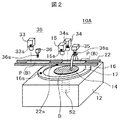
図2は、本実施形態におけるボンディイングヘッド35、ニードル36、ウェハリング16、それらの光学系38の構成図及びの黒色の4角形で示す振動計の一種である加速度センサの配置を示す図である。光学系38は、ニードル36の塗布位置を把握するプリフォーム部光学系33と、ボンディングヘッド35が搬送されてきた基板Bにボンディングするボンディング位置を把握するボンディング部光学系34と、ボンディングヘッド35がウェハ14からピックアップするダイDのピックアップ位置を把握するウェハ部光学系15とを有する。各部光学系は、対象に対して照明する照明装置とカメラを有する。ウェハ14において網目状にダイシングされたダイDは、ウェハリング16に固定されたダイシングテープ17に固定されている。以下の説明では、振動計として加速度センサを例に説明するが、振動を検知することができるものであれば、加速度センサに限定されるものではない。
FIG. 2 is a diagram showing the configuration of the
加速度センサは、ボンディングヘッド35と、ニードル36と、ウェハリング16と、プリフォーム部光学系33と、ボンディング部光学系34と、ウェハ部光学系15と、フレームフィーダ22等の被駆動体に接着剤や両面テープ、ボルト等で被駆動体の振動を感度良く検知できるように被駆動体の振動が大きい先端部や先端部に近い部位等に密着するように固定させており、それぞれの符号に添え字sで示されている。各加速度センサは、X、Y及びZ方向の振動を検出する能力を有する。
The acceleration sensor is bonded to a driven body such as a bonding
この構成によって、それぞれの加速度センサにより検出された被駆動体の振動を監視しながら、振動が所定のレベル(値)に減衰した時に、ボンディングヘッド35によるダイDのピックアップ、ニードル36によるダイ接着剤塗布、ボンディングヘッド35によるダイDの基板Bへのボンディング等の動作を開始する指示をすることにより、ボンディング動作等をより早く行うことができる。しかも、スループットが向上するのみならず、ダイのボンディングやピックアップ、接着剤の塗布等、それぞれの処理を振動が減衰したタイミングで実行することにより、それぞれの処理における振動の影響が低減され、正確に或いは確実にそれぞれの処理を行うことができる。また、ダイボンディング時や接着剤塗布時の振動や位置精度不足、ボンディングヘッド35等のチルトに起因するダイの接着状態不良や塗布不良、を低減できる。なお、加速度センサが検知する振動を監視する際には、搭載する加速度センサの仕様により監視すべき出力値は異なるが、例えば、±1.5G(重力加速度)のレンジで加速度を測定することが可能である加速度センサを搭載した場合は、加速度センサから出力された出力電圧の値(閾値)が、加速度0.30Gに相当する240mVとなった時に、ダイボンディング等を開始する指示を行うことにより、一定のボンディング精度を維持することが可能である。もちろん、要求されるボンディング精度・接着剤の塗布精度等に応じて加速度センサにおける閾値を変更することで、様々な仕様のボンディング精度等に対応可能である。
With this configuration, while monitoring the vibration of the driven body detected by each acceleration sensor, when the vibration is attenuated to a predetermined level (value), the die D is picked up by the
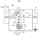
図3は、本発明のダイボンダ10の第2の実施形態10Bを上から見た概念図である。実施形態10Aは、ボンディングヘッド35がウェハ14からダイDを吸着してピックアップし、吸着したそのダイDを基板Bに装着するダイボンダである。
FIG. 3 is a conceptual view of the
一方、実施形態10Bは、ウェハ14からダイDをピックアップする専用のピックアップヘッド85がピックアップしたダイDを一度中間ステージ8に載置し、ボンディングヘッド35が中間ステージ8に載置されたダイDをピックアップし、ピックアップしたダイDを基板Bにボンディングするダイボンダである。このダイボンダには、ピックアップヘッド85にも加速度センサ85を設けている。なお、80は、ピックアップヘッド85のY駆動軸である。また、ボンディングヘッド35及びピックアップヘッド85のX、Z及びθ駆動軸は省略している。
なお、図3における符号は、実施形態10Aと同じ機能を有するものは同じ符号を示している。
On the other hand, in the
In addition, the code | symbol in FIG. 3 has shown the same code | symbol as what has the same function as
後述実施例1乃至4においては、図2、図3に示した加速度センサは、必ずしも全て必要でない場合もあり、逆にその他の構成要素、例えば、ボンドヘッド35sやボンド光学系34s、ウェハ光学系15sの他に、ワーク搬送用の爪であるフレームフィーダ22、ワークを固定するためのボンディングステージ22bに必要ならば設けてもよい。
In Examples 1 to 4 to be described later, all of the acceleration sensors shown in FIGS. 2 and 3 may not always be necessary. Conversely, other components such as a
図4は上述した動作を制御する制御系40の概略構成図で、実施形態10Aを例として示す図である。制御系40は、大別して、主としてCPUで構成される制御・演算部41と、記憶装置42と、入出力装置43と、バスライン44と、電源部45とを有する。記憶装置42は、処理プログラムなどを記憶しているRAMで構成されている主記憶装置42aと、制御に必要な制御データや画像データ等を記憶している、HDDや不揮発性メモリ等の記憶媒体で構成されている補助記憶装置42bとを有する。入出力装置43は、装置状態や情報等を表示するモニタ43aと、オペレータの指示を入力するタッチパネル43bと、モニタを操作するマウス43cと、光学系38からの画像データを取り込む画像取込装置43dと、ピックアップ装置12のXYテーブル(図示せず)やZY駆動軸60等のモータ65を制御するモータ制御装置43eと、加速度センサの信号や照明装置などのスイッチ等の信号部66から信号を取り込み又は制御するI/O信号制御装置43fとを有する。制御・演算部41はバスライン44を介して、例えば、加速度センサから出力された加速度と相関する電圧値等の必要なデータを取込み、例えば、加速度センサから出力された出力電圧が800mVである場合は加速度が1Gであるとして処理・演算する。その後、添え字sを有する加速度センサから出力された値を常時もしくは定期的に監視し、その出力値が、予め設定した加速度センサの出力値に対する閾値(例えば、加速度が0.3Gに相当する電圧値)よりも小さくなったタイミングでダイボンディング等を開始する等の信号を出力する処理を行う。そして、ダイボンディングやダイピックアップ等の処理動作中の加速度が予め設定された所定の閾値を超えないようにボンディングヘッド35等の制御を行う。この閾値は、ダイボンディングに要求される精度に応じて変更することができる。上記処理と並行もしくは前後して、モニタ43a等に各部に搭載された添え字sを有する加速度センサの出力電圧値もしくはその出力電圧値を加速度に変換したデータや情報を送信する。
FIG. 4 is a schematic configuration diagram of the
次に、本発明の実施形態の特徴である加速度センサの活用例を説明する。
(実施例1)
第1の実施例は、実施形態10A、10Bにおいて、ボンディングヘッド35に加速度センサ35sを設け、ボンディング時間、すなわちスループットを短縮できる例である。図5は、実施形態10A、10Bにおいてボンディングするときの状況を模式的に示す図でもある。
Next, an application example of the acceleration sensor, which is a feature of the embodiment of the present invention, will be described.
(Example 1)
The first example is an example in which, in the
ボンディングヘッド35は、その先端側に加速度センサ35sを有する。加速度センサ35sを可能な限りボンディングヘッド35の先端近くに設けることによってボンディングヘッドの振動を感度よく検出できる。その結果、振動の減衰も正確に検知することができ、動作を開始するタイミングも正確に判断・制御でき、また、振動が減衰したタイミングを見極めた上で精度よくダイをボンディングできる。その為には、加速度センサは小型の方が望ましく、例えば、メムス(MEMS: Micro Electro Mechanical Systems)センサを用いるとよい。
The
多連リードフレームBtは、フレームフィーダ22によってボンディングステージ22b上のボンディング位置に搬送され、その後、ボンディング部光学系34によって、リードフレームB(B1、B2、B3)の上にあるボンディング位置が検出される。そのボンディング位置の情報に基づいて、ボンディングヘッド35は、Y駆動軸55、X駆動軸70あるいはθ駆動軸によってボンディング位置の真上に移動する。
The multiple lead frame Bt is conveyed to the bonding position on the
ボンディングヘッド35がボンディング位置の真上にきた時、基本的には、フレームフィーダ22が停止し、ボンディング部光学系34によって既にボンディング位置が検出され、ボンディングヘッド35は、正確にボンディングできる状態になっている。
When the
この時、ボンディングヘッド35は、Z駆動軸50によって、コレット35cで吸着したダイDをリードフレームB上のボンディング位置の直前(略真上)まで降下させる。このタイミングで、加速度センサ35sが、ボンディングヘッドの先端の振動を検知・監視する。そして、その振動レベルが所定の範囲内、例えば、加速度が0.5G以下(出力電圧400mV以下)に収まったと検知・判断されたら、ボンディングヘッド35は、即時にダイDを降下させて、リードフレームBに押圧しながらボンディングする。
At this time, the
ボンディングヘッド35の先端の振動が減衰するまでの時間は、ボンディングヘッド35の構成や、ダイサイズなどによって異なるが、従来は、例えば、ボンディングヘッド35が基板B直前で停止したときの振動が所定レベル以下に達したときの減衰時間が約0.80sであると実験的に知られている場合は、減衰時間のバラつきなどを加味して、0.33s程度の余裕時間を持たせて、これらの時間の和である約1.13sの予め設定された時間を待ってからボンディングしていた。
The time until the vibration at the tip of the
一方、本実施例1では、加速度センサ35sによって、振動が所定のレベルにまで減衰したことを検知したらすぐにボンディング動作を開始できるので、余裕時間分、例えば少なくとも0.33sの期待値をもってボンディング時間を短縮できる。さらに、実験的にはボンディングヘッド35が基板B直前で停止して振動が所定レベル以下に減衰するまで時間が約0.80sを下回る場合、すなわち、振動が0.60sで減衰した場合は、ボンディングヘッド35が基板B直前で停止してから0.60s経過後すぐに、ボンディング動作を開始することが可能である。
On the other hand, in the first embodiment, the bonding operation can be started as soon as it is detected by the
実施形態10Aのニードル36、実施形態10Bのピックアップヘッド85(図3参照)にそれぞれ加速度センサを設けることによって、以下の実施例で説明しないダイ接着材の塗布処理、ボンディング35による中間ステージ8(図3参照)からのダイDのピックアップ処理、ピックアップヘッド85により中間ステージへの載置処理等において、実施例1で説明したボンディングヘッド35のボンディング処理と同様に、それぞれの処理時間を短縮できる。
By providing an acceleration sensor to each of the
(実施例2)
第2実施例は、実施形態10A、10Bにおいて、ボンディング部光学系34及びフレームフィーダ22に設けた加速度センサ34s、22sを活用し、ボンディング位置の検出時間を短縮できる例である。
(Example 2)
The second example is an example in which the bonding position
図5において、多連リードフレームBtは、フレームフィーダ22によってボンディングステージ22b上のボンディング位置に搬送される。ボンディング部光学系34は、駆動軸34dによって制御・駆動され、個々のリードフレームBの上方を順次移動しながらダイDがボンディングされるそれぞれのボンディング位置を検出する。駆動軸34dは、ボンディング部光学系34をX,Y方向に移動させるX駆動軸34x、Y駆動軸34yを有する。
In FIG. 5, the multiple lead frame Bt is conveyed to a bonding position on the
ボンディング位置を正確に検出するためには、特に最初のリードフレームB1に対しては、フレームフィーダ22とボンディング部光学系34が共に振動レベルが所定の範囲内、例えば、フレームフィーダ22とボンディング部光学系34のそれぞれにおける加速度が0.30G以下(出力電圧240mV以下)等に収まっていることが重要である。どちらか一方の振動レベルが所定の範囲を超える場合は、ボンディング部光学系34から得られる画像は、所定の位置誤差以上をもって検出される等、画像が振動によりブレてしまうことにより正確にボンディング位置を検出できない。
In order to accurately detect the bonding position, particularly for the first lead frame B1, the vibration level of both the
そこで、加速度センサ34s、22sにより検出されるボンディング部光学系34とフレームフィーダ22の振動レベルが所定の範囲内に入ったらすぐに画像を取得し、正確なボンディング位置を検出する。ここで、ボンディング部光学系34と、ボンディング部光学系34によって撮像される対象(被写体)であるリードフレームBを搬送するフレームフィーダ22の双方に、加速度センサ34s、22sを搭載することにより、ボンディング部光学系34が振動しているのか、それとも撮像対象であるフレームフィーダ22上のリードフレームBが振動しているのか、またそれぞれの振動がどの程度であるのか、を検出できる。それにより、ボンディング部光学系34かフレームフィーダ22のいずれか一方の振動が未だ減衰していない段階にボンディング動作を開始してしまうことが精度悪化の原因となり、ボンディング精度が低減することを防ぐことができる。従来は、実施例1で述べたように、フレームフィーダ22、ボンディング部光学系34のそれぞれの振動減衰時間に対してそれぞれの余裕時間分を設定・加算して、フレームフィーダ22、またはボンディング部光学系34のそれぞれの構成における振動減衰時間と余裕時間の和の長い方で規定される時間を待って、画像を取り込んでいる。従って、フレームフィーダ22における振動減衰時間が0.9sで余裕時間が0.4sであり、ボンディング部光学系34における振動減衰時間が0.7sで余裕時間が0.2sである場合は、フレームフィーダ22とボンディング部光学系34のそれぞれの構成における振動減衰時間と余裕時間の和は、1.3s、0.9sとなることから、振動が所定の範囲まで減衰するまでの時間が長いフレームフィーダ22の振動が減衰するまでの時間を待って、画像を取り込むこととなる。
Therefore, as soon as the vibration levels of the bonding unit
なお、2、3番目のリードフレームB2、B3に対しては、フレームフィーダ22は既に停止しているので、ボンディング部光学系34の加速度センサ34sのみを監視すればよい。また、上述で例示したフレームフィーダ22とボンディング部光学系34の減衰時間とは逆に、1番目のリードフレームB1においても、ボンディング部光学系34による振動の減衰時間が、フレームフィーダ22による減衰時間に比べ長ければ、ボンディング部光学系34の加速度センサ34sのみを監視してもよい。
For the second and third lead frames B2 and B3, since the
従って、実施例2においても、実施例1と同様に、ボンディング部光学系34によるボンディング位置を正確に検出でき、検出処理において期待値として余裕時間分処理時間を短縮できる。また、常にフレームフィーダ22とボンディング部光学系34の振動を検知することにより、装置構成や動作環境・運転状況によっては、ボンディング精度を維持したまま余裕時間分以上の時間を短縮することも可能である。
Accordingly, also in the second embodiment, as in the first embodiment, the bonding position by the bonding unit
(実施例3)
第3実施例は、実施形態10A、10Bにおいて、ボンディングヘッド35もしくはピックアップヘッド85によってダイDをピックアップするときに、ウェハ部光学系15とウェハリング16に設けた加速度センサ15s、16sを活用し、ピックアップ位置検出時間を短縮できる例である。
Example 3
The third example uses the
図6は、実施形態10A、10Bにおいて、ピックアップヘッド85によってダイDをピックアップするときの状況を模式的に示す図で、ウェハ部光学系15が、ピックアップヘッド85によってピックアップされるダイDの位置を検出する状態を示す図である。ピックアップは、実施形態10Aではボンディングヘッド35で、実施形態10Bではピックアップヘッド85で行うが、基本的には同じ動作である。図6では、代表して、ピックアップヘッド85の例を記している。
FIG. 6 is a diagram schematically showing a situation when the die D is picked up by the
ピックアップ装置12は、ウェハユニット51と、ピックアップヘッド85の先端部にあるコレット85cがダイDを吸着し易くするためにウェハのダイDを突き上げる突き上げユニット52と、これらを固定する基台53とを有する。ウェハユニット51は、ウェハ14を保持するウェハリング16と、ウェハリング16をリードフレーム等である基板と平行な面でθ回転させる回転駆動機構16aとを有する。
The
突き上げユニット52は、ダイDを突き上げる突き上げ部54aを昇降(Z方向に移動)させる突き上げ機構(図示せず)をその内部に有する駒54、駒54を基台53上でXY方向に移動させるXY駆動部54bと、駒54をZ方向に移動させるZ駆動部及び基板と平行な面でθ回転させるθ回転駆動部とを具備するZθ駆動部54cを有する。
The push-up
ピックアップヘッド85もZθ駆動部54cと同様にZ方向に移動させるZ駆動部及び基板と平行な面でθ回転させるθ回転駆動部とを具備する。即ち、ピックアップヘッド85及び駒54は、X、Y、Zの3方向の3次元自由度とθ回転のθ自由度の4自由度を持ち、ウェハユニット51はθ回転の自由度を持つ。
また、ウェハ部光学系15は、ボンディング光学系34の駆動軸34d(図5参照)と同様にX、Y方向に移動させる駆動軸15d(図3参照)を有する。
The
Further, the wafer
このような構成において、ウェハ部光学系15がダイDpのピックアップ位置を検出するために、まず、回転駆動機器16aがウェハリング16を回転させ、予め定められた位置にピックアップするダイDpを移動させる。この移動と前後してウェハ部光学系15が駆動軸15dによってピックアップ位置の上に移動し、ダイDpを撮像し、ダイDpの正確なピックアップ位置を検出する。ダイDpのピックアップ位置を正確かつ迅速に検出するためには、実施例2と同様に、ウェハリング16、ウェハ部光学系15の振動レベル(加速度)が共に所定の範囲内、例えば、加速度0.70G以下(出力電圧値560mV以下/加速度センサの検出レンジが±1.5Gの場合)に収まったら、ウェハ部光学系15によって、撮像することが重要である。ウェハリング16またはウェハ部光学系15のどちらか一方の振動レベルが所定の範囲内でなければ、ウェハ部光学系15から得られる画像は、所定の位置誤差以上をもって検出される。
In such a configuration, in order for the wafer unit
そこで、実施例3は、実施例2と同様に、加速度センサ15s、16sが共に所定の振動レベル範囲内に入ったら、従来例と異なり、即時に画像を取得するので、正確なピックアップ位置をより短時間で検出できる。
Thus, in the third embodiment, as in the second embodiment, when both the
また、駒54が回転駆動機器16aの回転動作と前後して移動する場合にも、駒54の移動による振動が最終的にはウェハリング16の振動となるので、加速度センサ15s、16sにより振動を検出・監視すればよい。勿論、駒54のXY駆動部54bに加速度センサを設けてもよい。
Further, even when the
従って、実施例3においても、実施例1と同様に、ウェハ部光学系15によるピックアップ位置検出処理において、期待値として少なくとも余裕時間分の処理時間を短縮できる。しかも、実施例2と同様にピックアップ位置を正確に検出できる。
Therefore, in the third embodiment, similarly to the first embodiment, in the pickup position detection process by the wafer
(実施例4)
第4実施例は、実施形態10A、10Bにおいて、ボンディングヘッド35もしくはピックアップヘッド85がダイDをピックアップするときに、ボンディングヘッド35もしくはピックアップヘッド85と駒54のZθ駆動部54cに設けた加速度センサ35sもしくは85s、54sを活用し、ピックアップ処理時間を短縮できる例である。実施例4も図6を用いて説明する。
Example 4
In the fourth example, in the
実施例3で説明した、ピックアップ位置検出処理後、ウェハ部光学系15はピックアップヘッド85と干渉しない位置に移動し、ピックアップヘッド85はピックアップ位置に移動し、ピックアップ位置にあるダイDpのZ方向の直前(真上)の位置(高さ)まで下降する。ピックアップヘッド85が下降するときには、ダイDpのθ方向の回転ずれを調整するため、ピックアップヘッド85のθ軸も駆動する。これらの動きに前後して、突き上げ部54bがダイDpに接触する直前まで上昇させる。その後、突き上げ部54bをさらに上昇させてダイDpに接触させて突き上げ、ピックアップヘッド85の先端部にあるコレット85cでダイDpを吸着・保持して、ピックアップする。
After the pickup position detection processing described in the third embodiment, the wafer unit
ピックアップヘッド85でダイDpを正確かつ確実にピックアップするためには、少なくとも、ピックアップヘッド85に設けた加速度センサ85sが検出するピックアップヘッド85の振動レベルが所定の範囲内に収まることが重要である。特に、ピックアップヘッド85と突き上げ部54aを同時に移動させて行う場合は、ピックアップヘッド85とZθ駆動部54cに設けた加速度センサ85sと54sが検出する振動レベルが共に所定の範囲内に収まった後にピックアップ動作を開始することが重要である。ピックアップヘッド85または突き上げ部54aのどちらか一方の振動レベルが所定の範囲内に収まっていなければ、ピックアップ位置ズレが発生し、確実にピックアップできない場合がある。
In order to pick up the die Dp accurately and reliably by the
そこで、ピックアップヘッド85と駒54の突き上げ部54aとを同時に動作させて行う場合には、加速度センサ85s、54sが検出する振動レベル(加速度)が共に所定の範囲内、例えば、搭載される加速度センサにより異なるが、加速度0.50G以下(出力電圧400mV以下)に収まったら、従来例と異なり、即時にピックアップヘッド85の降下動作と突き上げ部54cによる突き上げ動作を開始し、ダイDpをピックアップする。
Therefore, when the
すなわち、従来例と異なり、ピックアップヘッド85の移動及びダイDpに接する直前の位置までの降下動作を妨げずに突き上げ部54aによる突き上げ動作を先行させ、その後、ピックアップヘッド85を降下させるときには、加速度センサ85sが検出するピックアップヘッド85の振動レベルが所定の範囲内に収まったら、すぐにダイDpをピックアップする。
That is, unlike the conventional example, when the
従って、実施例4においても、実施例1と同様に、ピックアップ処理において、期待値として余裕時間分の処理時間を短縮できる。しかも、実施例4において、ピックアップヘッド85によって、ダイDpを確実にピックアップできる。
Therefore, in the fourth embodiment, similarly to the first embodiment, in the pickup process, the processing time corresponding to the margin time can be shortened as an expected value. Moreover, in the fourth embodiment, the die Dp can be reliably picked up by the
(実施例5)
今まで説明した実施例1乃至4は、ボンディング処理やピックアップ処理等、それぞれ独立した動作において、ボンディング精度を維持したまま、それぞれの処理時間を短縮する効果について述べた。しかしながら、各処理は完全に独立して動作することはできないが、例えば下記に示すように、ある処理が動作中に他の処理が行われ、それぞれの動きにより生じる振動がダイボンダ全体に影響する、振動の干渉状態になり得る場合がある。
(Example 5)
In the first to fourth embodiments described so far, the effects of shortening the processing time while maintaining the bonding accuracy in the independent operations such as the bonding process and the pickup process have been described. However, although each process cannot operate completely independently, for example, as shown below, another process is performed while a certain process is in operation, and vibration caused by each movement affects the entire die bonder. There may be a vibration interference state.
第1の例は、実施形態1、2のダイボンダ10A、10Bにおいて、ダイDをウェハ14からピックアップする処理中に、基板Bがフレームフィーダ22で搬送される場合である。その場合、フレームフィーダ22の振動が実施例2、3のピックアップ処理に影響する場合がある。
The first example is a case where the substrate B is transferred by the
第2の例は、実施形態2のダイボンダ10Bにおいて、ボンディングヘッド35が実施例1で示したボンディング処理中に、ピックアップヘッド85がX、Y方向に移動、または駒54がX,Y方向に移動する場合がある。その場合、ピックアップヘッド85、駒54の移動が、実施例1で示したようなボンディング処理に影響する場合がある。
In the second example, in the
第3の例は、実施形態2のダイボンダ10Bにおいて、ピックアップヘッド85が実施例3、4で示したピックアップ位置検出またはピックアップ処理中に、ボンディングヘッド85がX、Y方向に移動する場合がある。その場合、ボンディングヘッド35の移動が、実施例3、4で示したピックアップ位置検出またはピックアップ処理に影響する場合がある
上記のような場合は、関連した場所の加速度センサも監視して処理を行わなければならないし、その監視する加速度センサの数も多くなり、従来では、その分余裕時間を長くとる必要である。
In the third example, in the
本発明では、振動の発生に関連する構成に加速度センサを搭載する数が多くなればなるほど、ボンディング精度を維持したまま、振動源の特定や振動減衰時間の予測・監視、さらには各処理に要する時間の短縮効果が大きくなる。 In the present invention, the greater the number of acceleration sensors mounted in the configuration related to the occurrence of vibration, the more accurate the identification of the vibration source, the prediction and monitoring of the vibration damping time, and each processing are required while maintaining the bonding accuracy. The effect of shortening time is increased.
(実施例6)
また、実施例5で示した例において、例えば各処理の重要度を設定し、干渉する処理関係の振動源の移動を遅延させて重ならないように学習させて、干渉する処理を減少させて、全体として処理タイムチャートを確立することにより、処理時間を短縮できる。
Example 6
Further, in the example shown in the fifth embodiment, for example, the importance level of each process is set, the movement of the interfering process-related vibration source is delayed and learned so as not to overlap, the interfering process is reduced, By establishing a processing time chart as a whole, processing time can be shortened.
また、一般的に全ての加速度センサを監視することによって、ある処理と干渉する処理関係の振動源を見つけることができる。 In general, by monitoring all the acceleration sensors, it is possible to find a processing-related vibration source that interferes with a certain process.
従って、各処理の能力、例えばボンディングヘッドの移動速度、移動長さ等に基づいて、各処理のタイムチャートを詳細に決めなくても、干渉関係にある処理を検索しながら各処理を進めて行き、各処理のタイムチャートを確立できる。最初は処理時間が長くなるが、処理を進めていくに連れて全体として処理時間を短くでき、スル―プットを向上できる。また、運転状況が変わることにより振動が減衰する時間も変化するので、運転状況の変化に応じて処理時間を最適化し、スループットを向上させることができる。 Therefore, based on the capability of each process, for example, the bonding head's moving speed, moving length, etc., it is possible to proceed with each process while searching for interfering processes without having to determine the time chart of each process in detail. A time chart for each process can be established. Initially, the processing time becomes longer, but as the processing proceeds, the processing time can be shortened as a whole, and the throughput can be improved. In addition, since the time for which the vibration is attenuated also changes due to the change of the driving situation, the processing time can be optimized according to the change of the driving situation and the throughput can be improved.
以上のように本発明の実施形態における実施例を説明したが、上述の説明に基づいて当業者にとって種々の代替例、修正又は変形が可能であり、本発明はその趣旨を逸脱しない範囲で前述の種々の代替例、修正又は変形を包含するものである。 As described above, the examples of the embodiment of the present invention have been described. However, various alternatives, modifications, and variations can be made by those skilled in the art based on the above description, and the present invention is described above without departing from the scope of the present invention. It encompasses various alternatives, modifications or variations.
1:ウェハ供給部 2:ワーク供給・搬送部
3:ダイボンディング部 10、10A、10B:ダイボンダ
12:ピックアップ装置 14:ウェハ
15:ウェハ部光学系 15s:ウェハ部光学系の加速度センサ
16:ウェハリング 16s:ウェハリングの加速度センサ
22:フレームフィーダ 22sフレームフィーダの加速度センサ
31:プリフォーム部 32:ボンディングヘッド部
33:プリフォーム光学系 33s:リフォーム光学系の加速度センサ
34:ボンディング部光学系 34s:ボンディング部光学系の加速度センサ
35:ボンディングヘッド 35s:ボンディングヘッドの加速度センサ
36:ニードル 36s:ニードルの加速度センサ
38:光学系 40:制御系
41:制御・演算部 42:記憶装置
50:Z駆動軸 51:ウェハユニット
52:突き上げユニット 54:駒
54a:突き上げ部 54c:Zθ駆動部
54s:Zθ駆動部の加速度センサ
55;Y駆動軸 60:ZY駆動軸
80Y駆動軸 85:ピックアップヘッド
85s:ピックアップヘッドの加速度センサ
B:基板(リードフレーム) D:ダイ
Dp:ピックアップするダイ
1: Wafer supply unit 2: Workpiece supply / conveyance unit 3: Die bonding
Claims (18)
所定の処理を行う被駆動体と、
前記被駆動体を駆動する駆動部と、
前記被駆動体は該被駆動体の振動を検出する振動計を有し、かつ、
前記振動計が検出した振動の検出結果に基づいて、前記被駆動体による処理動作を制御する制御手段を有し、
前記被駆動体の前記処理動作により生ずる振動と干渉する他の被駆動体に設けられ、前記他の被駆動体の前記処理動作により生ずる他の振動を検出する他の振動計を有し、
前制御手段は、前記被駆動体の前記処理動作により生ずる振動及び前記他の被駆動体の前記処理動作により生ずる他の振動のそれぞれが共に所定の値以下になった時に、前記被駆動体又は前記他の被駆動体の動作を開始させる、
ことを特徴とするダイボンダ。 A die bonder for picking up a die from a wafer and bonding the die to a work that has been conveyed,
A driven body that performs predetermined processing;
A drive unit for driving the driven body;
The driven body has a vibrometer for detecting the vibration of the driven body; and
Based on the detection result of vibration detected by the vibrometer, the control means for controlling the processing operation by the driven body,
Another vibrometer provided on another driven body that interferes with vibration generated by the processing operation of the driven body and detecting other vibration generated by the processing operation of the other driven body;
The pre-control means is configured such that when each of the vibration generated by the processing operation of the driven body and the other vibration generated by the processing operation of the other driven body is equal to or less than a predetermined value, the driven body or Starting the operation of the other driven body,
A die bonder characterized by that.
前記被駆動体は、前記ダイを前記ワークに装着するボンディングヘッドであり、
前記処理動作の開始は、前記ワークに前記ダイを装着する直前で停止している前記ボンディングヘッドが前記ダイを前記ワークに装着するために降下する動作の開始である、
ことを特徴とするダイボンダ。 The die bonder according to claim 1,
The driven body is a bonding head for mounting the die to the work,
The start of the processing operation is the start of an operation in which the bonding head stopped immediately before mounting the die on the workpiece is lowered to mount the die on the workpiece.
A die bonder characterized by that.
前記被駆動体は、前記ダイをウェハからピックアップするピックアップヘッドであり、
前記処理動作の開始は、前記ウェハから前記ダイをピックアップする直前で停止している前記ピックアップヘッドが前記ダイに向かって降下する動作の開始である、
ことを特徴とするダイボンダ。 The die bonder according to claim 1,
The driven body is a pickup head that picks up the die from a wafer;
The start of the processing operation is the start of an operation in which the pickup head stopped immediately before picking up the die from the wafer is lowered toward the die.
A die bonder characterized by that.
前記被駆動体は、前記ダイを中間ステージからピックアップするボンディングヘッドであり、
前記処理動作の開始は、前記中間ステージから前記ダイをピックアップする直前で停止している前記ボンディングヘッドが前記ダイに向かって降下する動作の開始である、
ことを特徴とするダイボンダ。 The die bonder according to claim 1,
The driven body is a bonding head that picks up the die from an intermediate stage;
The start of the processing operation is the start of an operation in which the bonding head stopped immediately before picking up the die from the intermediate stage is lowered toward the die.
A die bonder characterized by that.
前記被駆動体は、前記ダイまたは前記ワークの位置を検出する光学系であり、
前記処理動作の開始は、前記光学系が前記ダイまたは前記ワークを撮像する動作の開始である、
ことを特徴とするダイボンダ。 The die bonder according to claim 1,
The driven body is an optical system that detects the position of the die or the workpiece,
The start of the processing operation is the start of an operation in which the optical system images the die or the workpiece.
A die bonder characterized by that.
所定の処理を行う被駆動体と、
前記被駆動体を駆動する駆動部と、
前記被駆動体は該被駆動体の振動を検出する振動計を有し、かつ、
前記振動計が検出した振動の検出結果に基づいて、前記被駆動体による処理動作を制御する制御手段を有し、
複数の前記被駆動体のそれぞれが前記振動計を有し、
前記制御手段は、それぞれの前記振動計が検出した複数の前記被駆動体のそれぞれの前記処理動作により生ずる複数の振動の検出結果に基づいて、複数の前記振動が互いに干渉しないように、一又は二以上の前記被駆動体による前記処理動作を制御する、
ことを特徴とするダイボンダ。 A die bonder for picking up a die from a wafer and bonding the die to a work that has been conveyed,
A driven body that performs predetermined processing;
A drive unit for driving the driven body;
The driven body has a vibrometer for detecting the vibration of the driven body; and
Based on the detection result of vibration detected by the vibrometer, the control means for controlling the processing operation by the driven body,
Each of the plurality of driven bodies has the vibrometer,
Based on the detection results of the plurality of vibrations generated by the processing operations of the plurality of driven bodies detected by the respective vibrometers, the control means is configured to prevent the plurality of vibrations from interfering with each other. Controlling the processing operation by two or more of the driven bodies;
A die bonder characterized by that.
前記制御手段は、複数の前記振動が互いに干渉しないように複数の前記振動が生ずるパターンを学習し、複数の前記被駆動体の前記処理動作のタイムチャートを作成し、前記タイムチャートに基づいて複数の前記被駆動体の前記処理動作を制御する、
ことを特徴とするダイボンダ。 The die bonder according to claim 6,
The control means learns a pattern in which a plurality of vibrations occur so that the plurality of vibrations do not interfere with each other, creates a time chart of the processing operation of the plurality of driven bodies, and sets a plurality of times based on the time chart. Controlling the processing operation of the driven body of
A die bonder characterized by that.
前記制御手段は、前記振動が所定の値以下になった時に、前記被駆動体の前記処理動作を開始させる、
ことを特徴とするダイボンダ。 The die bonder according to claim 7, wherein
The control means starts the processing operation of the driven body when the vibration becomes a predetermined value or less.
A die bonder characterized by that.
前記被駆動体は、前記ダイを前記ワークに装着するボンディングヘッドであり、
前記処理動作の開始は、前記ワークに前記ダイを装着する直前で停止している前記ボンディングヘッドが前記ダイを前記ワークに装着するために降下する動作の開始である、
ことを特徴とするダイボンダ。 The die bonder according to claim 8, wherein
The driven body is a bonding head for mounting the die to the work,
The start of the processing operation is the start of an operation in which the bonding head stopped immediately before mounting the die on the workpiece is lowered to mount the die on the workpiece.
A die bonder characterized by that.
被駆動体を駆動部により駆動し、該被駆動体の駆動により生ずる振動を検出し、検出された前記振動の検出結果に基づいて、前記被駆動体による処理動作を制御し、
前記被駆動体の前記処理動作により生ずる振動と干渉する他の被駆動体の動作により生ずる他の振動を検出し、
前記動作の開始は、前記被駆動体の前記処理動作により生ずる振動及び前記他の被駆動体の前記処理動作により生ずる他の振動のそれぞれが共に所定の値以下になった時に、前記被駆動体又は前記他の被駆動体の動作を開始させる、
ことを特徴とするボンディング方法。 A bonding method of picking up a die from a wafer and bonding the die to a conveyed work,
Driving the driven body by a driving unit, detecting vibration generated by driving the driven body , and controlling processing operation by the driven body based on the detected detection result of the vibration ;
Detecting other vibrations caused by operations of other driven bodies that interfere with vibrations caused by the processing operations of the driven bodies;
The start of the operation is performed when the vibration generated by the processing operation of the driven body and the other vibration generated by the processing operation of the other driven body are both equal to or lower than a predetermined value. Or start the operation of the other driven body,
A bonding method characterized by the above.
前記被駆動体は、前記ダイを前記ワークに装着するボンディングヘッドであり、
前記処理動作の開始は、前記ワークに前記ダイを装着する直前で停止している前記ボンディングヘッドが前記ダイを前記ワークに装着するために降下する動作の開始である、
ことを特徴とするボンディング方法。 The bonding method according to claim 10 , wherein
The driven body is a bonding head for mounting the die to the work,
The start of the processing operation is the start of an operation in which the bonding head stopped immediately before mounting the die on the workpiece is lowered to mount the die on the workpiece.
A bonding method characterized by the above.
前記被駆動体は、前記ダイをウェハからピックアップするピックアップヘッドであり、
前記処理動作の開始は、前記ウェハから前記ダイをピックアップする直前で停止している前記ピックアップヘッドが前記ダイに向かって降下する動作の開始である、
ことを特徴とするボンディング方法。 The bonding method according to claim 10 , wherein
The driven body is a pickup head that picks up the die from a wafer;
The start of the processing operation is the start of an operation in which the pickup head stopped immediately before picking up the die from the wafer is lowered toward the die.
A bonding method characterized by the above.
前記被駆動体は、前記ダイを中間ステージからピックアップするボンディングヘッドであり、
前記処理動作の開始は、前記中間ステージから前記ダイをピックアップする直前で停止している前記ボンディングヘッドが前記ダイに向かって降下する動作の開始である、
ことを特徴とするボンディング方法。 The bonding method according to claim 10 , wherein
The driven body is a bonding head that picks up the die from an intermediate stage;
The start of the processing operation is the start of an operation in which the bonding head stopped immediately before picking up the die from the intermediate stage is lowered toward the die.
A bonding method characterized by the above.
前記被駆動体は、前記ダイまたは前記ワークの位置を検出する光学系であり、
前記処理動作の開始は、前記光学系が前記ダイまたは前記ワークを撮像する動作の開始である、
ことを特徴とするボンディング方法。 The bonding method according to claim 10 , wherein
The driven body is an optical system that detects the position of the die or the workpiece,
The start of the processing operation is the start of an operation in which the optical system images the die or the workpiece.
A bonding method characterized by the above.
被駆動体を駆動部により駆動し、該被駆動体の駆動により生ずる振動を検出し、検出された前記振動の検出結果に基づいて、前記被駆動体による処理動作を制御し、
複数の前記被駆動体のそれぞれの前記処理動作により生ずる複数の前記振動を検出し、複数の前記振動の検出結果に基づいて、複数の前記振動が互いに干渉しないように、一又は二以上の前記被駆動体による前記処理動作を制御する、
ことを特徴とするボンディング方法。 A bonding method of picking up a die from a wafer and bonding the die to a conveyed work ,
Driving the driven body by a driving unit, detecting vibration generated by driving the driven body, and controlling processing operation by the driven body based on the detected detection result of the vibration;
One or two or more of the vibrations generated by the processing operations of the plurality of driven bodies are detected, and based on the detection results of the plurality of vibrations, the plurality of vibrations do not interfere with each other. Controlling the processing operation by the driven body;
A bonding method characterized by the above.
前記制御は、複数の前記振動が互いに干渉しないように複数の前記振動が生ずるパターンを学習し、複数の前記被駆動体の前記処理動作のタイムチャートを作成し、前記タイムチャートに基づいて複数の前記被駆動体の前記処理動作を制御する、
ことを特徴とするボンディング方法。 The bonding method according to claim 15 , wherein
The control learns a pattern in which a plurality of vibrations occur so that the plurality of vibrations do not interfere with each other, creates a time chart of the processing operation of the plurality of driven bodies, and generates a plurality of times based on the time chart. Controlling the processing operation of the driven body;
A bonding method characterized by the above.
前記制御は、前記振動が所定の値以下になった時に、前記被駆動体の前記処理動作を開始させる、The control starts the processing operation of the driven body when the vibration becomes a predetermined value or less.
ことを特徴とするボンディング方法。A bonding method characterized by the above.
前記被駆動体は、前記ダイを前記ワークに装着するボンディングヘッドであり、The driven body is a bonding head for mounting the die to the work,
前記処理動作の開始は、前記ワークに前記ダイを装着する直前で停止している前記ボンディングヘッドが前記ダイを前記ワークに装着するために降下する動作の開始である、The start of the processing operation is the start of an operation in which the bonding head stopped immediately before mounting the die on the workpiece is lowered to mount the die on the workpiece.
ことを特徴とするボンディング方法。A bonding method characterized by the above.
Priority Applications (1)
| Application Number | Priority Date | Filing Date | Title |
|---|---|---|---|
| JP2014053699A JP6374189B2 (en) | 2014-03-17 | 2014-03-17 | Die bonder and bonding method |
Applications Claiming Priority (1)
| Application Number | Priority Date | Filing Date | Title |
|---|---|---|---|
| JP2014053699A JP6374189B2 (en) | 2014-03-17 | 2014-03-17 | Die bonder and bonding method |
Publications (3)
| Publication Number | Publication Date |
|---|---|
| JP2015177110A JP2015177110A (en) | 2015-10-05 |
| JP2015177110A5 JP2015177110A5 (en) | 2017-03-23 |
| JP6374189B2 true JP6374189B2 (en) | 2018-08-15 |
Family
ID=54255982
Family Applications (1)
| Application Number | Title | Priority Date | Filing Date |
|---|---|---|---|
| JP2014053699A Active JP6374189B2 (en) | 2014-03-17 | 2014-03-17 | Die bonder and bonding method |
Country Status (1)
| Country | Link |
|---|---|
| JP (1) | JP6374189B2 (en) |
Families Citing this family (6)
| Publication number | Priority date | Publication date | Assignee | Title |
|---|---|---|---|---|
| JP7102113B2 (en) * | 2017-09-11 | 2022-07-19 | ファスフォードテクノロジ株式会社 | Manufacturing method of die bonding equipment and semiconductor equipment |
| JP6862015B2 (en) * | 2017-09-29 | 2021-04-21 | 株式会社新川 | Mounting device |
| KR102037972B1 (en) * | 2018-05-30 | 2019-10-29 | 세메스 주식회사 | Die bonding method |
| JP7161870B2 (en) * | 2018-06-27 | 2022-10-27 | ファスフォードテクノロジ株式会社 | Die bonder and semiconductor device manufacturing method |
| JP7128697B2 (en) * | 2018-09-19 | 2022-08-31 | ファスフォードテクノロジ株式会社 | Die bonding apparatus and semiconductor device manufacturing method |
| CN117080127B (en) * | 2023-10-11 | 2024-01-05 | 江苏快克芯装备科技有限公司 | Chip suction abnormality detection device and detection method |
Family Cites Families (3)
| Publication number | Priority date | Publication date | Assignee | Title |
|---|---|---|---|---|
| JP3216300B2 (en) * | 1993-01-30 | 2001-10-09 | ソニー株式会社 | Method for checking the state of equipment having a head and a push-up part |
| JP5713787B2 (en) * | 2011-04-28 | 2015-05-07 | 芝浦メカトロニクス株式会社 | Electronic component mounting equipment |
| JP5771847B2 (en) * | 2011-09-27 | 2015-09-02 | Jukiオートメーションシステムズ株式会社 | Mounting apparatus, electronic component mounting method, board manufacturing method, and program |
-
2014
- 2014-03-17 JP JP2014053699A patent/JP6374189B2/en active Active
Also Published As
| Publication number | Publication date |
|---|---|
| JP2015177110A (en) | 2015-10-05 |
Similar Documents
| Publication | Publication Date | Title |
|---|---|---|
| JP6374189B2 (en) | Die bonder and bonding method | |
| KR101449247B1 (en) | Die bonder and method of position recognition of die | |
| KR101923274B1 (en) | Die bonder and bonding method | |
| CN109494173B (en) | Chip mounting apparatus and method for manufacturing semiconductor device | |
| JP6166069B2 (en) | Die bonder and collet position adjustment method | |
| TW201608665A (en) | Die pick-up unit, die bonding apparatus including the same, and method of bonding dies | |
| CN108364880B (en) | Semiconductor manufacturing apparatus and method for manufacturing semiconductor device | |
| JP2007012929A (en) | Method for checking interference of surface mounting machine, device for checking interference, surface mounting machine with the device and mounting system | |
| JP5309503B2 (en) | POSITIONING DEVICE, POSITIONING METHOD, AND SEMICONDUCTOR MANUFACTURING DEVICE HAVING THEM | |
| JP2010135574A (en) | Transfer apparatus | |
| JP6424097B2 (en) | NOZZLE INSPECTION DEVICE, NOZZLE INSPECTION METHOD, AND COMPONENT CONVEYING DEVICE | |
| JP2021158166A (en) | Die bonding device and manufacturing method of semiconductor device | |
| JP2008117869A (en) | Surface mounting device | |
| JP2015204377A (en) | Processing apparatus | |
| CN110931366B (en) | Chip mounting apparatus and method for manufacturing semiconductor device | |
| JP6615199B2 (en) | Detection method | |
| JP5408148B2 (en) | Component mounting apparatus and component mounting method | |
| JP6880158B1 (en) | Work transfer device, work transfer method, transfer body manufacturing method, semiconductor device manufacturing method, and die bonder | |
| JP2010192817A (en) | Pickup method and pickup device | |
| JP2007158053A (en) | Electronic component mounting equipment | |
| JP5826701B2 (en) | Chip positioning device, chip positioning method, and die bonder | |
| JP6391225B2 (en) | Flip chip bonder and flip chip bonding method | |
| JP7017723B2 (en) | Inspection method | |
| WO2024084703A1 (en) | Component-mounting work machine and mounting line | |
| JP2013191890A (en) | Positioning device and positioning method, and semiconductor manufacturing device with the same |
Legal Events
| Date | Code | Title | Description |
|---|---|---|---|
| A521 | Request for written amendment filed |
Free format text: JAPANESE INTERMEDIATE CODE: A523 Effective date: 20170215 |
|
| A621 | Written request for application examination |
Free format text: JAPANESE INTERMEDIATE CODE: A621 Effective date: 20170215 |
|
| A977 | Report on retrieval |
Free format text: JAPANESE INTERMEDIATE CODE: A971007 Effective date: 20171025 |
|
| A131 | Notification of reasons for refusal |
Free format text: JAPANESE INTERMEDIATE CODE: A131 Effective date: 20171107 |
|
| A521 | Request for written amendment filed |
Free format text: JAPANESE INTERMEDIATE CODE: A523 Effective date: 20171219 |
|
| A131 | Notification of reasons for refusal |
Free format text: JAPANESE INTERMEDIATE CODE: A131 Effective date: 20180109 |
|
| A521 | Request for written amendment filed |
Free format text: JAPANESE INTERMEDIATE CODE: A523 Effective date: 20180309 |
|
| TRDD | Decision of grant or rejection written | ||
| A01 | Written decision to grant a patent or to grant a registration (utility model) |
Free format text: JAPANESE INTERMEDIATE CODE: A01 Effective date: 20180703 |
|
| A61 | First payment of annual fees (during grant procedure) |
Free format text: JAPANESE INTERMEDIATE CODE: A61 Effective date: 20180719 |
|
| R150 | Certificate of patent or registration of utility model |
Ref document number: 6374189 Country of ref document: JP Free format text: JAPANESE INTERMEDIATE CODE: R150 |
|
| R250 | Receipt of annual fees |
Free format text: JAPANESE INTERMEDIATE CODE: R250 |
|
| R250 | Receipt of annual fees |
Free format text: JAPANESE INTERMEDIATE CODE: R250 |
|
| R250 | Receipt of annual fees |
Free format text: JAPANESE INTERMEDIATE CODE: R250 |