JP6367678B2 - Electric steering lock device - Google Patents
Electric steering lock device Download PDFInfo
- Publication number
- JP6367678B2 JP6367678B2 JP2014208018A JP2014208018A JP6367678B2 JP 6367678 B2 JP6367678 B2 JP 6367678B2 JP 2014208018 A JP2014208018 A JP 2014208018A JP 2014208018 A JP2014208018 A JP 2014208018A JP 6367678 B2 JP6367678 B2 JP 6367678B2
- Authority
- JP
- Japan
- Prior art keywords
- lock
- electric steering
- lock device
- slider
- follower
- Prior art date
- Legal status (The legal status is an assumption and is not a legal conclusion. Google has not performed a legal analysis and makes no representation as to the accuracy of the status listed.)
- Active
Links
Images


Description
本発明は、車両の駐車時にステアリングホイールの回転をロックする電動ステアリングロック装置に関するものである。 The present invention relates to an electric steering lock device that locks the rotation of a steering wheel when a vehicle is parked.
従来、電動モータの駆動力によって作動するロックボルトを、ステアリングシャフトに設けられた係合凹部に係合させることで、車両のステアリングをロックして、盗難を防止するようにした電動ステアリングロック装置が知られている。 2. Description of the Related Art Conventionally, there has been an electric steering lock device that locks the steering of a vehicle and prevents theft by engaging a lock bolt that is operated by the driving force of an electric motor with an engagement recess provided on a steering shaft. Are known.
特許文献1には、ネジ機構を用いてロックボルトを作動させる構成が記載されている。
このような電動ステアリングロック装置では、ステアリングシャフトにロックボルトが係合した状態で、ステアリングシャフトにトルクがかかると、ロックボルトに据え切りトルクがかかって係合凹部の内側面がロックボルトに圧接した状態になっているために、ロックボルトを前記係合凹部から引き抜けない場合がある。
Patent Document 1 describes a configuration in which a lock bolt is operated using a screw mechanism.
In such an electric steering lock device, when torque is applied to the steering shaft in a state where the lock bolt is engaged with the steering shaft, a stationary torque is applied to the lock bolt, and the inner side surface of the engaging recess is pressed against the lock bolt. Because of this state, the lock bolt may not be pulled out from the engaging recess.
この対策として、ロックボルトの引き抜き力を大きくするために、ネジ機構のネジのピッチを小さくして構成する方法が考えられるが、このように構成した場合には、ロックボルトの引き抜きに時間がかかり、ひいては、車両の走行開始までに時間がかかるおそれがあった。 As a countermeasure, in order to increase the pulling force of the lock bolt, a method of reducing the screw pitch of the screw mechanism can be considered, but in this case, it takes time to pull out the lock bolt. As a result, there is a possibility that it takes time until the vehicle starts to travel.
本発明の課題は、ロックボルトの引き抜き力を大きくすることができ、かつ、ロックボルトの引き抜き時間を短くできる電動ステアリングロック装置を提供することである。 An object of the present invention is to provide an electric steering lock device that can increase the pull-out force of the lock bolt and shorten the lock bolt pull-out time.
本発明は、以下のような解決手段により、前記課題を解決する。なお、理解を容易にするために、本発明の実施形態に対応する符号を付して説明するが、これに限定されるものではない。 The present invention solves the above problems by the following means. In addition, in order to make an understanding easy, although the code | symbol corresponding to embodiment of this invention is attached | subjected and demonstrated, it is not limited to this.
請求項1の発明は、ステアリングシャフトに係合するロック位置と、その係合が解除されるアンロック位置との間を移動可能なロック部材(30)と、電動モータの駆動力によって正逆回転可能な回転部材(40)と、前記ロック部材、及び、前記回転部材の一方側に雄ネジ部(32a)、他方側に雌ネジ部(40b)を備えて、前記回転部材の回転に応じて前記ロック部材をロック位置、又は、アンロック位置に向けて移動させるネジ機構と、前記ロック部材をアンロック位置に向けて付勢するスプリング(80)とを設け、前記雄ネジ部と前記雌ネジ部との噛み合いが外れる非噛合い部(32g,40c)を前記ロック部材及び前記回転部材のそれぞれに設け、前記雄ネジ部と前記雌ネジ部との噛み合いが外れた非噛合い状態において、前記ロック部材は、前記スプリングの付勢力によってアンロック位置に向けて移動可能に構成されていること、を特徴とする電動ステアリングロック装置(1)である。 According to the first aspect of the present invention, the lock member (30) is movable between a lock position where the steering shaft is engaged and an unlock position where the engagement is released. A possible rotating member (40), the locking member, and a male screw part (32a) on one side of the rotating member and a female screw part (40b) on the other side, and according to the rotation of the rotating member A screw mechanism for moving the lock member toward the lock position or the unlock position, and a spring (80) for biasing the lock member toward the unlock position are provided, and the male screw portion and the female screw In the non-engagement state in which the non-engagement part (32g, 40c) that disengages from the part is provided in each of the lock member and the rotation member, and the engagement between the male screw part and the female screw part is released, Serial locking member, that is configured to be movable toward the unlock position by the biasing force of the spring, an electric steering lock device according to claim (1).
請求項2の発明は、請求項1に記載の電動ステアリングロック装置において、アンロック位置にある前記ロック部材(30)を、前記ネジ機構の噛み合いが開始される位置まで移動させるカム機構(32h,40d)を備えたこと、を特徴とする電動ステアリングロック装置(1)である。 According to a second aspect of the present invention, in the electric steering lock device according to the first aspect, the cam mechanism (32h, 32) moves the lock member (30) in the unlocked position to a position where the engagement of the screw mechanism is started. 40 d) an electric steering lock device (1).
請求項3の発明は、請求項2に記載の電動ステアリングロック装置において、前記カム機構は、前記回転部材(40)側に設けられた原節(40d)と、前記ロック部材(30)側に設けられた従節(32h)とを備え、前記ロック部材がアンロック位置にあるときには、前記回転部材の回転方向において前記原節と前記従節とが係合可能に位置し、前記ロック部材がロック位置方向に移動して前記ネジ機構(32a,40b)の噛み合いが開始された後は、前記原節と前記従節とは、前記ロック部材の進退方向にずれて前記回転部材の回転方向に係合不能となるように形成されていること、を特徴とする電動ステアリングロック装置(1)である。 According to a third aspect of the present invention, in the electric steering lock device according to the second aspect, the cam mechanism includes an original joint (40d) provided on the rotating member (40) side and a locking member (30) side. A follower (32h) provided, and when the locking member is in the unlocked position, the original joint and the follower are positioned so as to be engageable in the rotation direction of the rotating member, and the locking member is After moving in the lock position direction and the meshing of the screw mechanism (32a, 40b) is started, the original joint and the follower are displaced in the advancing / retreating direction of the locking member and in the rotating direction of the rotating member. An electric steering lock device (1) characterized by being formed so as to be incapable of engagement.
請求項4の発明は、請求項2又は請求項3に記載の電動ステアリングロック装置において、前記カム機構(32h,40d)の作動ピッチを前記ネジ機構(32a,40b)の作動ピッチよりも長くしたこと、を特徴とする電動ステアリングロック装置(1)である。 According to a fourth aspect of the present invention, in the electric steering lock device according to the second or third aspect, the operating pitch of the cam mechanism (32h, 40d) is longer than the operating pitch of the screw mechanism (32a, 40b). This is an electric steering lock device (1).
請求項5の発明は、請求項2又は請求項3に記載の電動ステアリングロック装置において、アンロック位置にある前記ロック部材(30)を、前記スプリング(80)の付勢力に抗して、前記カム機構の原節(40d)と従節(32h)とが前記回転部材(40)の回転方向に係合可能な位置に保持するストッパ部(20a)を設けたこと、を特徴とする電動ステアリングロック装置(1)である。 According to a fifth aspect of the present invention, in the electric steering lock device according to the second or third aspect, the locking member (30) in the unlocked position is resisted against a biasing force of the spring (80). An electric steering system characterized in that a stopper portion (20a) is provided to hold the original joint (40d) and the follower joint (32h) of the cam mechanism at a position where the rotating member (40) can be engaged in the rotational direction. Lock device (1).
請求項6の発明は、請求項2から請求項5までのいずれか1項に記載の電動ステアリングロック装置において、前記回転部材(40)は、内周面に前記ネジ機構の雌ネジ部(40b)、及び、前記カム機構の原節(40d)が形成された円筒状の部材であり、前記ロック部材(30)は、前記回転部材に挿通されて、外周面に前記ネジ機構の雄ネジ部(32a)、及び、前記カム機構の従節(32h)が設けられた略棒状部材であり、前記ロック部材がアンロック位置にあり、前記カム機構の原節と従節とが前記回転部材の回転方向に係合可能な位置にある場合に、前記ネジ機構の雄ネジ部と雌ネジ部とは、前記ロック部材の進退方向に離間して設けられていること、を特徴とする電動ステアリングロック装置(1)である。 According to a sixth aspect of the present invention, in the electric steering lock device according to any one of the second to fifth aspects, the rotary member (40) has an internal thread portion (40b) of the screw mechanism on an inner peripheral surface. ), And a cylindrical member in which an original joint (40d) of the cam mechanism is formed, and the lock member (30) is inserted through the rotating member, and has a male screw portion of the screw mechanism on an outer peripheral surface. (32a) and a substantially rod-like member provided with a follower (32h) of the cam mechanism, the lock member is in an unlocked position, and the original and follower of the cam mechanism are connected to the rotating member. The electric steering lock, wherein the male screw portion and the female screw portion of the screw mechanism are provided apart from each other in the advancing / retreating direction of the lock member when the screw mechanism is located at a position engageable with the rotation direction. Device (1).
本発明によれば、電動ステアリングロック装置は、ロックボルトの引き抜き力を大きくすることができ、かつ、ロックボルトの引き抜き時間を短くできる。 According to the present invention, the electric steering lock device can increase the pull-out force of the lock bolt and shorten the lock bolt pull-out time.
以下、本発明を実施するための最良の形態について図面等を参照して説明する。 The best mode for carrying out the present invention will be described below with reference to the drawings.
(実施形態)
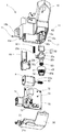
図1は、本発明による電動ステアリングロック装置1の実施形態を示す分解斜視図である。
図2は、電動ステアリングロック装置1のロック状態を示す縦断面図である。
図3は、電動ステアリングロック装置1のアンロック状態を示す縦断面図である。
図4は、回転部材40を示す斜視図である。
なお、図1を含め、以下に示す各図は、模式的に示した図であり、各部の大きさ、形状は、理解を容易にするために、適宜誇張して示している。
また、以下の説明では、具体的な数値、形状、材料等を示して説明を行うが、これらは、適宜変更することができる。
さらに、以下の説明中において、特に説明しない限り、上下等の向きを示す記載は、図1から図3中における向きを指すものとする。
(Embodiment)
FIG. 1 is an exploded perspective view showing an embodiment of an electric steering lock device 1 according to the present invention.
FIG. 2 is a longitudinal sectional view showing a locked state of the electric steering lock device 1.
FIG. 3 is a longitudinal sectional view showing the unlocked state of the electric steering lock device 1.
FIG. 4 is a perspective view showing the rotating
In addition, each figure shown below including FIG. 1 is the figure shown typically, and the magnitude | size and shape of each part are exaggerated suitably for easy understanding.
In the following description, specific numerical values, shapes, materials, and the like are shown and described, but these can be changed as appropriate.
Further, in the following description, unless otherwise specified, the description indicating the direction such as up and down refers to the direction in FIGS. 1 to 3.
本発明に係る電動ステアリングロック装置1は、電動によって不図示のステアリングシャフト(ステアリングホイール)の回動をロック/アンロックするものである。電動ステアリングロック装置1は、非磁性体の金属(例えば、マグネシウム合金)で構成されたハウジング10と、ハウジング10の下面開口部を覆う金属製のカバー20とを外装として有している。
The electric steering lock device 1 according to the present invention locks / unlocks the rotation of a steering shaft (steering wheel) (not shown) by electric drive. The electric steering lock device 1 includes a
ハウジング10は、矩形ボックス状に成形されており、その上部には円弧状の凹部10aが形成されている。この凹部10aには、不図示のコラムチューブが嵌め込まれ、このコラムチューブは、ハウジング10に取付けられる不図示の円弧状のブラケットによってハウジング10に固定される。なお、図示しないが、コラムチューブ内には、ステアリングシャフトが挿通しており、このステアリングシャフトの一端には、ステアリングホイールが取付けられている。ステアリングシャフトの他端は、ステアリングギヤボックスに連結されている。そして、運転者がステアリングホイールを回動操作すれば、その回転は、ステアリングシャフトを経てステアリングギヤボックスに伝達され、操舵機構が駆動されて左右一対の前輪が転舵されて所要の操舵がなされる。
The
また、ハウジング10の側部には、矩形のコネクタ配設部10bが開口している。さらに、ハウジング10の側部には、ピン11が圧入される円孔状のピン孔10cが形成されている。
In addition, a rectangular
カバー20は、矩形平板状に成形されており、その内面(上面)には3つのブロック状のピン留め部21(図1には1つのみ図示)と有底筒状のギヤ保持部22が一体に立設されている。ここで、3つのピン留め部21は、ハウジング10のピン孔10cの位置に対応する箇所に形成されており、これらには、ピン11が圧入される円孔状のピン挿通孔21a(図1には1つのみ図示)が形成されている。
The
カバー20は、ハウジング10の下面開口部を下方から覆うようにハウジング10の下端部内周に嵌め込まれている。カバー20は、ハウジング10の側部に形成された3つのピン孔10cに挿通するピン11をカバー20に立設された3つのピン留め部21に形成されたピン挿通孔21aに圧入することによってハウジング10に固定される。
The
ハウジング10には、ロック部材収納部10fと基板収納部10gが形成されており、これらロック部材収納部10fと基板収納部10gとの間には、ギヤカバー60が配置されている。このギヤカバー60は、後述のウォームギヤ62に塗布されたグリスが基板70側へ飛散することを防止する。
The
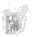
また、ロック部材収納部10fには、ロックユニット(ロック部材)30が収納されている。ロックユニット30は、ステアリングシャフトに係合するロック位置と、その係合が解除されるアンロック位置との間を移動可能となるように、以下のように構成されている。ロックユニット30は、下端部外周に雄ネジ部32aが刻設されたスライダ32と、このスライダ32内に上下動可能に収容されたプレート状のロックボルト31とを有している。ここで、ロックボルト31には、上下方向に長い長孔31aが形成されており、ロックボルト31は、長孔31aに横方向に挿通するピン34によってスライダ32に連結されている。なお、ピン34は、スライダ32に横方向に貫設されたピン挿通孔32bに圧入によって挿通保持されている。
A lock unit (lock member) 30 is stored in the lock
ロックボルト31は、ハウジング10に形成された矩形のロックボルト挿通孔10d内に上下動可能に嵌合している。ロックボルト31は、ロックボルト31とスライダ32の隔壁32fとの間に縮装されたスプリング52によってスライダ32から上方に常時付勢されている。通常は、ロックボルト31の長孔31aの下部がピン34に係合することによってロックボルト31は、スライダ32と共に上下動する。
The
また、スライダ32の上部外周には、図中で水平に延びるアーム32dと、回り止め部32cとが一体に形成されている。アーム32dは、ハウジング10内においてスライダ32の移動と共に上下動可能に収容されている。回り止め部32cは、ハウジング10に形成された係合溝10eに係合してスライダ32の回転を規制する。そして、アーム32dの先端部には、横断面形状が矩形の磁石収納部32eが形成されている。この磁石収納部32eには、四角柱状の磁石33が圧入によって収納されている。
In addition, an
また、スライダ32のアーム32dとハウジング10の上部内壁との間には、スプリング80がチャージされた状態で配置されている。このスプリング80は、スライダ32を図中の下方、すなわちアンロック位置へ向けて常時付勢している。
A
ハウジング10内に形成されたロック部材収納部10fには、円筒状の回転部材40が正逆回転可能に収容されている。回転部材40の下部である小径部42の外周は、カバー20の内面(上面)に立設されたギヤ保持部22によって回転可能に保持されている。そして、この回転部材40の小径部42の外周には、ウォームホイール40aが形成され、内周には、雌ネジ部40bが形成されている。
A cylindrical rotating
回転部材40の内部には、略棒状に形成されたスライダ32の下部が挿入されており、このスライダ32の下部外周に形成された雄ネジ部32aは、回転部材40の内周に形成された雌ネジ部40bが噛合い可能となっている。これら雄ネジ部32aと雌ネジ部40bとにより、回転部材40の回転に応じてロックボルト31及びスライダ32(ロックユニット30)をロック位置、又は、アンロック位置に向けて移動させるネジ機構が構成されている。
また、スライダ32の雄ネジ部32aの上方には、非噛合い部32gが設けられている。これと対応して、回転部材40の雌ネジ部40bの下方には、非噛合い部40cが設けられている。したがって、スライダ32の位置が下方のアンロック位置に近づくと所定の位置から、雄ネジ部32aと雌ネジ部40bとの噛合いが外れることとなる。雄ネジ部32aと雌ネジ部40bとの噛合いが外れる非噛合い状態となると、ロックボルト31及びスライダ32は、スプリング80の付勢力によってアンロック位置に向けて移動するようになっている。
A lower portion of a
Further, a
さらに、回転部材40の上部である大径部41の内周面には、ロックボルト31及びスライダ32の進退方向に傾斜して伸びる原節40dが部分的に突出して形成されている。これと対応してスライダ32の外周面には、ロックボルト31及びスライダ32の進退方向に傾斜して伸びる従節32hが部分的に突出して形成されている。本実施形態では、原節40d及び従節32hは、いずれも略対向する位置に2箇所設けられており、アンロック位置にあるロックボルト31及びスライダ32を、ネジ機構の噛み合いが開始される位置まで移動させるカム機構を構成している。このカム機構では、ロックボルト31及びスライダ32がアンロック位置にあるときには、回転部材40の回転方向において原節40dと従節32hとが係合可能に位置している。また、ロックボルト31及びスライダ32がロック位置方向に移動してネジ機構の噛み合いが開始された後は、原節40dと従節32hとは、ロックボルト31及びスライダ32の進退方向にずれて回転部材40の回転方向に係合不能となるように原節40dと従節32hとの位置が決められて配置されている。
また、原節40dと従節32hとからなるカム機構の作動ピッチは、雄ネジ部32aと雌ネジ部40bとからなるネジ機構の作動ピッチよりも長くなるように構成されている。
なお、これらネジ機構とカム機構とのより詳しい関係については、後述する。
Furthermore, an original joint 40d that extends in an inclined manner in the advancing / retreating direction of the
Further, the operation pitch of the cam mechanism composed of the original joint 40d and the follower joint 32h is configured to be longer than the operation pitch of the screw mechanism composed of the
A more detailed relationship between the screw mechanism and the cam mechanism will be described later.
ハウジング10に形成されたロック部材収納部10fには、電動モータ61が横置き状態で収納されている。この電動モータ61の出力軸61aには、小径のウォームギヤ62が出力軸61aと一体で回転するように取付けられている。このウォームギヤ62は、回転部材40の外周に形成されたウォームホイール40aとかみ合っている。ウォームギヤ62とウォームホイール40aとは、電動モータ61の出力軸61aの回転力をロックユニット30の進退力に変換する駆動機構を構成している。
An
一方、ハウジング10に形成された基板収納部10gには、その内面がロックユニット30の作動方向と平行となるように基板70が収納されている。この基板70の内面上下のロック位置とアンロック位置に対応する位置には、基板70をベース部として、磁気センサであるホール素子72,73がそれぞれ固定されている。これらのホール素子72,73と磁石33とによって作動位置検出機構が構成され、この作動位置検出機構によってロックユニット30の位置(ロック位置/アンロック位置)が検出される。また、基板70には、電動モータ61が接続されるモータ接続端子71と、コネクタ74とが設けられている。
On the other hand, the
また、カバー20の内面(図中の上面)には、スプリング80の付勢力に抗して、カム機構の原節40dと従節32hとが回転部材40の回転方向に係合可能な位置になるように、アンロック位置にあるロックボルト31及びスライダ32を保持するストッパ部20aが設けられている。
Further, on the inner surface (the upper surface in the drawing) of the
次に、ネジ機構とカム機構との関係に着目しながら、本実施形態の電動ステアリングロック装置1の動作を説明する。
先ず、図5及び図6を用いて、アンロック動作について説明する。
図5は、ロック状態にあるロックボルト31及びスライダ32と、回転部材40との関係を示す図である。
図6は、図5のロック状態から移行したアンロック状態にあるロックボルト31及びスライダ32と、回転部材40との関係を示す図である。
なお、図5及び図6を含めて以下に示す図では、従節32hとの位置関係を説明するために、本来は見ることができない原節40dを図示している。
図5に示すロック状態では、ネジ機構の雄ネジ部32aと雌ネジ部40bとが噛み合うことにより、ロックボルト31及びスライダ32がロック位置にある。よって、ロックボルト31は、ステアリングシャフトの凹部に係合し、ステアリングがロックされた状態となっている。この状態では、カム機構の原節40dと従節32hとは非係合状態となっている。
Next, the operation of the electric steering lock device 1 of the present embodiment will be described while paying attention to the relationship between the screw mechanism and the cam mechanism.
First, the unlocking operation will be described with reference to FIGS.
FIG. 5 is a diagram illustrating the relationship between the
FIG. 6 is a view showing the relationship between the rotating
In the drawings shown below including FIG. 5 and FIG. 6, the
In the locked state shown in FIG. 5, the
図5のロック状態からアンロック状態に移行させるために、電動モータ61が駆動させられて回転部材40が正転(図中の手前側が右方向に回転)すると、ネジ機構の雄ネジ部32aと雌ネジ部40bとの作用によって、ロックボルト31及びスライダ32は、アンロック方向(下側)に移動する。この状態では、ネジ機構によってロックボルト31及びスライダ32を駆動するので、仮にロックボルト31に据え切りトルクがかかって係合凹部の内側面がロックボルト31に圧接した状態になっていたとしても、強い力でロックボルト31を引き抜くことが可能である。また、このとき、カム機構の原節40dと従節32hとは、上下方向に相対的な位置がずれているので、互いに係合したり衝突したりすることはない。
In order to shift from the locked state of FIG. 5 to the unlocked state, when the
さらに回転部材40が正転を続けると、非噛合い部32g及び非噛合い部40cの上下方向の位置が、それぞれ雌ネジ部40b及び雄ネジ部32aと一致する(互いに対向する)ようになるので、ネジ機構の雄ネジ部32aと雌ネジ部40bとの噛み合いが外れる。これにより、ロックボルト31及びスライダ32は、スプリング80の付勢力によってアンロック方向に移動し、カバー20のストッパ部20aに当接することで、アンロック位置まで移動して図6の位置で停止する。
Further, when the rotating
このとき、カム機構の従節32hは、一対のカム機構の原節40dの間の空間を上から下に通過することにより、アンロック位置まで移動する。
しかし、仮に、ロックボルト31及びスライダ32のアンロック方向への移動中に従節32hと原節40dとが衝突して、従節32hが原節40dの傾斜にしたがって移動するようになったとしても、カム機構の作動ピッチが、ネジ機構の作動ピッチよりも長く設定されており、また、従節32hと原節40dとの係合はすぐに解除されるので、ロックボルト31及びスライダ32は、ネジ機構による移動速度よりも速くアンロック位置に移動することができる。したがって、本実施形態の電動ステアリングロック装置1は、アンロック動作を従来よりも格段に早く行うことが可能である。
At this time, the
However, if the
ロックボルト31及びスライダ32が図6に示すアンロック位置まで移動すると、不図示の制御部は、ホール素子73によって磁石33の磁力を検出し、ロックボルト31及びスライダ32がアンロック位置に移動したことを検出して、電動モータ61の駆動を停止し、ロック動作が完了する。
When the
次に、図7から図9を用いて、ロック動作について説明する。
図7は、アンロック状態にあるロックボルト31及びスライダ32と、回転部材40との関係を示す図である。
図8は、図7のアンロック状態からロック状態への移行途中におけるロックボルト31及びスライダ32と、回転部材40との関係を示す図である。
図9は、図7のアンロック状態から移行したロック状態におけるロックボルト31及びスライダ32と、回転部材40との関係を示す図である。
Next, the locking operation will be described with reference to FIGS.
FIG. 7 is a diagram illustrating the relationship between the
FIG. 8 is a diagram showing the relationship between the
FIG. 9 is a diagram showing the relationship between the
図7のアンロック状態では、ロックボルト31とステアリングシャフトの凹部との係合が解除されており、ステアリングがアンロック状態となっている。このとき、カム機構の従節32hと原節40dとは係合可能な状態にあり、ネジ機構の雄ネジ部32aと雌ネジ部40bとは、噛み合っておらず、ロックボルト31及びスライダ32の進退方向(図中の上下方向)に離間してずれている状態にある。
In the unlocked state of FIG. 7, the engagement between the
図7のアンロック状態からロック状態へ移行するために、電動モータ61が駆動して回転部材40が逆転(図中の手前側が左方向に回転)すると、カム機構の従節32hと原節40dとの作用により、ロックボルト31及びスライダ32は、スプリング80の付勢力に抗してロック方向(図中の上方)に移動を開始する。
In order to shift from the unlocked state of FIG. 7 to the locked state, when the
回転部材40が逆転を継続していくと、図8に示す状態までロックボルト31及びスライダ32が移動して、カム機構の従節32hが原節40dの上面の位置まで移動し、ネジ機構の雄ネジ部32aと雌ネジ部40bとの噛合いが開始される。これにより、ロックボルト31及びスライダ32は、引き続きネジ機構の雄ネジ部32aと雌ネジ部40bとの噛合いによってロック方向に移動を続ける。ネジ機構の雄ネジ部32aと雌ネジ部40bとの噛合いによってロックボルト31及びスライダ32が移動する状態に移行すると、その後は、カム機構の従節32hと原節40dとの係合が解除され、ロックボルト31及びスライダ32のロック位置方向への移動によって、従節32hと原節40dとは、上下方向に位置がずれるため、再度係合することはない。
When the
ロックボルト31及びスライダ32が図9に示すロック位置まで移動すると、ロックボルト31がステアリングシャフトの凹部に係合し、ステアリングがロックされる。また、制御部は、ホール素子72によって磁石33の磁力を検出し、ロックボルト31及びスライダ32がロック位置に移動したことを検出して、電動モータ61の駆動を停止して、ロック動作を完了する。
When the
以上説明したように、本実施形態によれば、電動ステアリングロック装置1は、ロックボルト31及びスライダ32をアンロック位置に向けて付勢するスプリング80を設け、ネジ機構の噛み合いが外れる非噛合い部32gと非噛合い部40cとをスライダ32及び回転部材40のそれぞれに設けている。また、ネジ機構の噛み合いが外れた非噛合い状態において、ロックボルト31及びスライダ32は、スプリング80の付勢力によってアンロック位置に向けて移動可能に構成されている。よって、ロックボルト31及びスライダ32をステアリングシャフトから引き抜く際には、ネジ機構を用いて強い力でロックボルト31及びスライダ32を引き抜くことができ、引き抜いた後は、スプリング80の付勢力によって短い時間でロックボルト31及びスライダ32をアンロック位置まで移動させることができる。すなわち、ロックボルト31及びスライダ32に据え切りトルクが係っている場合でも、ロックボルト31及びスライダ32を引き抜くことが可能となり、また、ロックボルト31及びスライダ32の全体的な引き抜き時間も短くすることが可能となる。
なお、アンロック動作に要する時間を短くできることから、ネジ機構のピッチを小さくしてロックボルト31を引き抜く力をより大きくするという設定を行うこともできる。
As described above, according to the present embodiment, the electric steering lock device 1 is provided with the
In addition, since the time required for the unlocking operation can be shortened, it is possible to perform a setting of increasing the force for pulling out the
また、電動ステアリングロック装置1は、アンロック位置にあるロックボルト31及びスライダ32を、ネジ機構の噛み合いが開始される位置まで移動させるカム機構を備えている。これにより、ロックボルト31及びスライダ32をアンロック作動させる際に、一度噛み合いが外れて離間したネジ機構の雄ネジ部32aと雌ネジ部40bとを、ロックボルト31をロック作動させる際に、カム機構によってロックボルト31及びスライダ32を移動させることで再び噛み合い可能な状態に戻すことができる。これにより、ロックボルト31及びスライダ32のロック作動を問題なく行うことができる。
Further, the electric steering lock device 1 includes a cam mechanism that moves the
さらに、電動ステアリングロック装置1において、ロックボルト31及びスライダ32がアンロック位置にあるときには、回転部材40の回転方向において原節40dと従節32hとが係合可能に位置し、ロックボルト31及びスライダ32がロック位置方向に移動してネジ機構の噛み合いが開始された後は、原節40dと従節32hとは、ロックボルト31及びスライダ32の進退方向にずれて回転部材40の回転方向に係合不能となるように形成されている。このようなカム機構をロックボルト31及びスライダ32と回転部材40に設けることで、部品点数を増やすことなく、簡単に構成することができる。また、ネジ機構が噛み合って作動している間は、カム機構の原節40dと従節32hとが回転部材40の回転方向に係合することはなく、ロックボルト31及びスライダ32の移動に支障をきたすことがない。
Further, in the electric steering lock device 1, when the
さらにまた、電動ステアリングロック装置1では、カム機構の作動ピッチをネジ機構の作動ピッチよりも長くなるように構成している。これにより、電動ステアリングロック装置1は、ロックボルト31及びスライダ32のロック作動にかかる時間を全てネジ機構で作動させる従来の形態と比較して短くすることができる。
また、仮に、ロックボルト31及びスライダ32のアンロック作動時に、ネジ機構の噛み合いが外れたロックボルト31及びスライダ32がスプリング80の付勢力でアンロック位置方向に移動したとする。この場合に、カム機構の原節40dと従節32hとがロックボルト31及びスライダ32の作動方向に係合し、その後、ロックボルト31及びスライダ32がカム機構の傾斜にしたがって移動しても、カム機構の作動ピッチはネジ機構の作動ピッチよりも長く構成されているため、アンロック作動にかかる時間を全てネジ機構で作動させる従来の形態と比較して短くすることができる。
Furthermore, the electric steering lock device 1 is configured such that the operating pitch of the cam mechanism is longer than the operating pitch of the screw mechanism. Thereby, the electric steering lock device 1 can shorten the time required for the lock operation of the
Further, it is assumed that the
また、電動ステアリングロック装置1では、アンロック位置にあるロックボルト31及びスライダ32を、スプリング80の付勢力に抗して、カム機構の原節40dと従節32hとが回転部材40の回転方向に係合可能な位置に保持するストッパ部20aを設けている。よって、電動ステアリングロック装置1は、カム機構の原節40dと従節32hとを常に係合状態に維持しておく必要がない。したがって、カム機構を小さく構成することが可能となり、回転部材40の小型化が可能であり、これにより、電動ステアリングロック装置1を小型化できる。
Further, in the electric steering lock device 1, the
以上説明した実施形態に限定されることなく、種々の変形や変更が可能であって、それらも本発明の範囲内である。よって、本発明は以上説明した各実施形態によって限定されることはない。 The present invention is not limited to the embodiment described above, and various modifications and changes are possible, and these are also within the scope of the present invention. Therefore, the present invention is not limited by the embodiments described above.
1 電動ステアリングロック装置
10 ハウジング
10a 凹部
10b コネクタ配設部
10c ピン孔
10d ロックボルト挿通孔
10e 係合溝
10f ロック部材収納部
10g 基板収納部
11 ピン
20 カバー
20a ストッパ部
21 ピン留め部
21a ピン挿通孔
22 ギヤ保持部
30 ロックユニット
31 ロックボルト
31a 長孔
32 スライダ
32a 雄ネジ部
32b ピン挿通孔
32c 回り止め部
32d アーム
32e 磁石収納部
32f 隔壁
32g 非噛合い部
32h 従節
33 磁石
34 ピン
40 回転部材
40a ウォームホイール
40b 雌ネジ部
40c 非噛合い部
40d 原節
41 大径部
42 小径部
52 スプリング
60 ギヤカバー
61 電動モータ
61a 出力軸
62 ウォームギヤ
70 基板
71 モータ接続端子
72 ホール素子
73 ホール素子
74 コネクタ
80 スプリング
DESCRIPTION OF SYMBOLS 1 Electric
Claims (6)
電動モータの駆動力によって正逆回転可能な回転部材と、
前記ロック部材、及び、前記回転部材の一方側に雄ネジ部、他方側に雌ネジ部を備えて、前記回転部材の回転に応じて前記ロック部材をロック位置、又は、アンロック位置に向けて移動させるネジ機構と、
前記ロック部材をアンロック位置に向けて付勢するスプリングとを設け、
前記雄ネジ部と前記雌ネジ部との噛み合いが外れる非噛合い部を前記ロック部材及び前記回転部材のそれぞれに設け、
前記雄ネジ部と前記雌ネジ部との噛み合いが外れた非噛合い状態において、前記ロック部材は、前記スプリングの付勢力によってアンロック位置に向けて移動可能に構成されていること、
を特徴とする電動ステアリングロック装置。 A lock member movable between a lock position for engaging with the steering shaft and an unlock position for releasing the engagement;
A rotating member that can rotate forward and backward by the driving force of the electric motor;
The lock member and the rotary member are provided with a male screw portion on one side and a female screw portion on the other side, and the lock member is directed to the lock position or the unlock position according to the rotation of the rotary member. A screw mechanism to be moved,
A spring for biasing the lock member toward the unlock position;
A non-engagement part that disengages the male screw part and the female screw part is provided in each of the lock member and the rotation member,
In a non-engagement state in which the male screw part and the female screw part are disengaged, the lock member is configured to be movable toward the unlock position by the biasing force of the spring;
An electric steering lock device.
アンロック位置にある前記ロック部材を、前記ネジ機構の噛み合いが開始される位置まで移動させるカム機構を備えたこと、
を特徴とする電動ステアリングロック装置。 In the electric steering lock device according to claim 1,
A cam mechanism for moving the lock member in the unlock position to a position where the engagement of the screw mechanism is started;
An electric steering lock device.
前記カム機構は、前記回転部材側に設けられた原節と、前記ロック部材側に設けられた従節とを備え、
前記ロック部材がアンロック位置にあるときには、前記回転部材の回転方向において前記原節と前記従節とが係合可能に位置し、
前記ロック部材がロック位置方向に移動して前記ネジ機構の噛み合いが開始された後は、前記原節と前記従節とは、前記ロック部材の進退方向にずれて前記回転部材の回転方向に係合不能となるように形成されていること、
を特徴とする電動ステアリングロック装置。 In the electric steering lock device according to claim 2,
The cam mechanism includes an original joint provided on the rotating member side, and a follower provided on the lock member side,
When the lock member is in the unlock position, the original clause and the follower are positioned so as to be engageable in the rotation direction of the rotating member,
After the locking member moves in the lock position direction and the meshing of the screw mechanism is started, the original joint and the follower are shifted in the advancing / retreating direction of the locking member and are engaged in the rotation direction of the rotating member. Being formed so that it cannot be combined,
An electric steering lock device.
前記カム機構の作動ピッチを前記ネジ機構の作動ピッチよりも長くしたこと、
を特徴とする電動ステアリングロック装置。 In the electric steering lock device according to claim 2 or claim 3,
The operating pitch of the cam mechanism is longer than the operating pitch of the screw mechanism;
An electric steering lock device.
アンロック位置にある前記ロック部材を、前記スプリングの付勢力に抗して、前記カム機構の原節と従節とが前記回転部材の回転方向に係合可能な位置に保持するストッパ部を設けたこと、
を特徴とする電動ステアリングロック装置。 In the electric steering lock device according to claim 2 or claim 3,
A stopper is provided for holding the lock member in the unlocked position at a position where the original and follower of the cam mechanism can be engaged in the rotation direction of the rotating member against the biasing force of the spring. Was it,
An electric steering lock device.
前記回転部材は、内周面に前記ネジ機構の雌ネジ部、及び、前記カム機構の原節が形成された円筒状の部材であり、
前記ロック部材は、前記回転部材に挿通されて、外周面に前記ネジ機構の雄ネジ部、及び、前記カム機構の従節が設けられた略棒状部材であり、
前記ロック部材がアンロック位置にあり、前記カム機構の原節と従節とが前記回転部材の回転方向に係合可能な位置にある場合に、前記ネジ機構の雄ネジ部と雌ネジ部とは、前記ロック部材の進退方向に離間して設けられていること、
を特徴とする電動ステアリングロック装置。 In the electric steering lock device according to any one of claims 2 to 5,
The rotating member is a cylindrical member in which an internal thread portion of the screw mechanism and an original thread of the cam mechanism are formed on an inner peripheral surface,
The lock member is a substantially rod-like member that is inserted into the rotating member and has an outer peripheral surface provided with a male screw portion of the screw mechanism and a follower of the cam mechanism,
When the lock member is in the unlocked position and the original and follower of the cam mechanism are in positions that can be engaged in the rotation direction of the rotating member, the male screw part and the female screw part of the screw mechanism Are spaced apart in the advancing and retreating direction of the locking member,
An electric steering lock device.
Priority Applications (1)
| Application Number | Priority Date | Filing Date | Title |
|---|---|---|---|
| JP2014208018A JP6367678B2 (en) | 2014-10-09 | 2014-10-09 | Electric steering lock device |
Applications Claiming Priority (1)
| Application Number | Priority Date | Filing Date | Title |
|---|---|---|---|
| JP2014208018A JP6367678B2 (en) | 2014-10-09 | 2014-10-09 | Electric steering lock device |
Publications (2)
| Publication Number | Publication Date |
|---|---|
| JP2016074392A JP2016074392A (en) | 2016-05-12 |
| JP6367678B2 true JP6367678B2 (en) | 2018-08-01 |
Family
ID=55950738
Family Applications (1)
| Application Number | Title | Priority Date | Filing Date |
|---|---|---|---|
| JP2014208018A Active JP6367678B2 (en) | 2014-10-09 | 2014-10-09 | Electric steering lock device |
Country Status (1)
| Country | Link |
|---|---|
| JP (1) | JP6367678B2 (en) |
Families Citing this family (2)
| Publication number | Priority date | Publication date | Assignee | Title |
|---|---|---|---|---|
| JP7112985B2 (en) * | 2019-04-22 | 2022-08-04 | 株式会社ホンダロック | electric steering lock device |
| JP2020175840A (en) * | 2019-04-22 | 2020-10-29 | 株式会社ホンダロック | Electric steering lock device |
Family Cites Families (4)
| Publication number | Priority date | Publication date | Assignee | Title |
|---|---|---|---|---|
| JP3206397B2 (en) * | 1995-11-13 | 2001-09-10 | 日本鋼管株式会社 | Screw joint structure such as steel pipe pile |
| FR2748054B1 (en) * | 1996-04-29 | 1998-05-22 | Valeo Securite Habitacle | MOTORIZED LOCKING DEVICE FOR A MOTOR VEHICLE COMPRISING IMPROVED MEANS FOR LIMITING THE STROKE OF THE LATCH |
| JP2006321454A (en) * | 2005-05-20 | 2006-11-30 | Yamaha Motor Co Ltd | Vehicle control device for saddle riding type vehicle |
| JP5887711B2 (en) * | 2010-11-16 | 2016-03-16 | 株式会社ジェイテクト | Lock device and electric power steering device |
-
2014
- 2014-10-09 JP JP2014208018A patent/JP6367678B2/en active Active
Also Published As
| Publication number | Publication date |
|---|---|
| JP2016074392A (en) | 2016-05-12 |
Similar Documents
| Publication | Publication Date | Title |
|---|---|---|
| JP4671762B2 (en) | Electric steering lock device | |
| JP5624822B2 (en) | Electric steering lock device | |
| JP6002015B2 (en) | Steering lock device | |
| JP4348245B2 (en) | Steering lock device | |
| JP6325207B2 (en) | Electric steering lock device | |
| US8833119B2 (en) | Electric steering lock device | |
| JP6367678B2 (en) | Electric steering lock device | |
| US20050268676A1 (en) | Motor-driven steering lock device | |
| JP5231375B2 (en) | Electric steering lock device | |
| JP5459844B2 (en) | Electric steering lock device | |
| JP6889526B2 (en) | Electric steering lock device | |
| JP5586342B2 (en) | Electric steering lock device | |
| JP6367679B2 (en) | Electric steering lock device | |
| JP5222236B2 (en) | Steering lock device | |
| JP6002085B2 (en) | Steering lock device | |
| JP2005343378A (en) | Electric steering lock device | |
| JP5967813B2 (en) | Electric steering lock device | |
| JP6109624B2 (en) | Electric steering lock device | |
| JP5283603B2 (en) | Electric steering lock device | |
| CN109204225B (en) | Antitheft safety lock pin system | |
| JP5551565B2 (en) | Steering lock device | |
| JP6355510B2 (en) | Steering lock device | |
| JP6355534B2 (en) | Electric steering lock device | |
| JP2016222113A (en) | Electric steering locking device | |
| JP6685703B2 (en) | Electric steering lock device |
Legal Events
| Date | Code | Title | Description |
|---|---|---|---|
| A621 | Written request for application examination |
Free format text: JAPANESE INTERMEDIATE CODE: A621 Effective date: 20171005 |
|
| A977 | Report on retrieval |
Free format text: JAPANESE INTERMEDIATE CODE: A971007 Effective date: 20180621 |
|
| TRDD | Decision of grant or rejection written | ||
| A01 | Written decision to grant a patent or to grant a registration (utility model) |
Free format text: JAPANESE INTERMEDIATE CODE: A01 Effective date: 20180703 |
|
| A61 | First payment of annual fees (during grant procedure) |
Free format text: JAPANESE INTERMEDIATE CODE: A61 Effective date: 20180705 |
|
| R150 | Certificate of patent or registration of utility model |
Ref document number: 6367678 Country of ref document: JP Free format text: JAPANESE INTERMEDIATE CODE: R150 |
|
| R250 | Receipt of annual fees |
Free format text: JAPANESE INTERMEDIATE CODE: R250 |