JP6358125B2 - コネクタ - Google Patents
コネクタ Download PDFInfo
- Publication number
- JP6358125B2 JP6358125B2 JP2015029439A JP2015029439A JP6358125B2 JP 6358125 B2 JP6358125 B2 JP 6358125B2 JP 2015029439 A JP2015029439 A JP 2015029439A JP 2015029439 A JP2015029439 A JP 2015029439A JP 6358125 B2 JP6358125 B2 JP 6358125B2
- Authority
- JP
- Japan
- Prior art keywords
- press
- press contact
- twisted pair
- wire
- contact
- Prior art date
- Legal status (The legal status is an assumption and is not a legal conclusion. Google has not performed a legal analysis and makes no representation as to the accuracy of the status listed.)
- Expired - Fee Related
Links
- 230000000630 rising effect Effects 0.000 claims description 16
- 238000000034 method Methods 0.000 claims description 9
- 230000015572 biosynthetic process Effects 0.000 claims description 5
- 239000000758 substrate Substances 0.000 claims description 5
- 238000005192 partition Methods 0.000 description 6
- 239000011248 coating agent Substances 0.000 description 3
- 238000000576 coating method Methods 0.000 description 3
- 239000004020 conductor Substances 0.000 description 3
- 238000005452 bending Methods 0.000 description 1
- 238000002788 crimping Methods 0.000 description 1
- 238000006073 displacement reaction Methods 0.000 description 1
- 229920003002 synthetic resin Polymers 0.000 description 1
- 239000000057 synthetic resin Substances 0.000 description 1
- 230000007704 transition Effects 0.000 description 1
Images


Classifications
-
- H—ELECTRICITY
- H01—ELECTRIC ELEMENTS
- H01R—ELECTRICALLY-CONDUCTIVE CONNECTIONS; STRUCTURAL ASSOCIATIONS OF A PLURALITY OF MUTUALLY-INSULATED ELECTRICAL CONNECTING ELEMENTS; COUPLING DEVICES; CURRENT COLLECTORS
- H01R4/00—Electrically-conductive connections between two or more conductive members in direct contact, i.e. touching one another; Means for effecting or maintaining such contact; Electrically-conductive connections having two or more spaced connecting locations for conductors and using contact members penetrating insulation
- H01R4/24—Connections using contact members penetrating or cutting insulation or cable strands
- H01R4/2416—Connections using contact members penetrating or cutting insulation or cable strands the contact members having insulation-cutting edges, e.g. of tuning fork type
- H01R4/242—Connections using contact members penetrating or cutting insulation or cable strands the contact members having insulation-cutting edges, e.g. of tuning fork type the contact members being plates having a single slot
- H01R4/2425—Flat plates, e.g. multi-layered flat plates
- H01R4/2429—Flat plates, e.g. multi-layered flat plates mounted in an insulating base
-
- H—ELECTRICITY
- H01—ELECTRIC ELEMENTS
- H01R—ELECTRICALLY-CONDUCTIVE CONNECTIONS; STRUCTURAL ASSOCIATIONS OF A PLURALITY OF MUTUALLY-INSULATED ELECTRICAL CONNECTING ELEMENTS; COUPLING DEVICES; CURRENT COLLECTORS
- H01R4/00—Electrically-conductive connections between two or more conductive members in direct contact, i.e. touching one another; Means for effecting or maintaining such contact; Electrically-conductive connections having two or more spaced connecting locations for conductors and using contact members penetrating insulation
- H01R4/24—Connections using contact members penetrating or cutting insulation or cable strands
- H01R4/2416—Connections using contact members penetrating or cutting insulation or cable strands the contact members having insulation-cutting edges, e.g. of tuning fork type
- H01R4/2445—Connections using contact members penetrating or cutting insulation or cable strands the contact members having insulation-cutting edges, e.g. of tuning fork type the contact members having additional means acting on the insulation or the wire, e.g. additional insulation penetrating means, strain relief means or wire cutting knives
- H01R4/245—Connections using contact members penetrating or cutting insulation or cable strands the contact members having insulation-cutting edges, e.g. of tuning fork type the contact members having additional means acting on the insulation or the wire, e.g. additional insulation penetrating means, strain relief means or wire cutting knives the additional means having two or more slotted flat portions
-
- H—ELECTRICITY
- H01—ELECTRIC ELEMENTS
- H01R—ELECTRICALLY-CONDUCTIVE CONNECTIONS; STRUCTURAL ASSOCIATIONS OF A PLURALITY OF MUTUALLY-INSULATED ELECTRICAL CONNECTING ELEMENTS; COUPLING DEVICES; CURRENT COLLECTORS
- H01R4/00—Electrically-conductive connections between two or more conductive members in direct contact, i.e. touching one another; Means for effecting or maintaining such contact; Electrically-conductive connections having two or more spaced connecting locations for conductors and using contact members penetrating insulation
- H01R4/70—Insulation of connections
-
- H—ELECTRICITY
- H01—ELECTRIC ELEMENTS
- H01R—ELECTRICALLY-CONDUCTIVE CONNECTIONS; STRUCTURAL ASSOCIATIONS OF A PLURALITY OF MUTUALLY-INSULATED ELECTRICAL CONNECTING ELEMENTS; COUPLING DEVICES; CURRENT COLLECTORS
- H01R13/00—Details of coupling devices of the kinds covered by groups H01R12/70 or H01R24/00 - H01R33/00
- H01R13/646—Details of coupling devices of the kinds covered by groups H01R12/70 or H01R24/00 - H01R33/00 specially adapted for high-frequency, e.g. structures providing an impedance match or phase match
- H01R13/6461—Means for preventing cross-talk
- H01R13/6463—Means for preventing cross-talk using twisted pairs of wires
Landscapes
- Connections By Means Of Piercing Elements, Nuts, Or Screws (AREA)
- Multi-Conductor Connections (AREA)
- Connector Housings Or Holding Contact Members (AREA)
- Coupling Device And Connection With Printed Circuit (AREA)
- Manufacturing Of Electrical Connectors (AREA)
- Connections Effected By Soldering, Adhesion, Or Permanent Deformation (AREA)
Description
複数のツイストペア線が圧接されるものであり、
前記ツイストペア線を構成する電線が個別に圧接される2つの圧接端子金具と、
前記圧接端子金具に形成された圧接部が、前記ツイストペア線の配索方向と交差する方向に並ぶように、前記2つの圧接端子金具を保持するホルダと、
前記ホルダに形成され、前記ツイストペア線を前記圧接部との圧接位置へ接近させる過程で、2本の前記電線を2つの前記圧接部と対応するように離間させる振分けリブと、
前記圧接端子金具に設けられ、前記ツイストペア線を構成する全ての電線を一括して保持する電線保持部と、
を備えているところに特徴を有する。
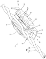
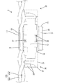
以下、本発明を具体化した実施例1を図1〜図9を参照して説明する。本実施例のコネクタCは、第1ツイストペア線40A(請求項記載のツイストペア線)と、第2ツイストペア線40B(請求項記載のツイストペア線)を圧接対象とする。第1ツイストペア線40Aは、2本の第1電線41A(請求項記載の電線)を捻りながら接近させて螺旋状に撚ったものである。第2ツイストペア線40Bも、第1ツイストペア線40Aと同様、2本の第2電線41B(請求項記載の電線)を捻りながら接近させて螺旋状に撚ったものである。コネクタCは、第1ツイストペア線40Aと第2ツイストペア線40Bを接続させる圧接タイプのジョイントコネクタCとしての機能を有し、両ツイストペア線40A,40Bを圧接する際の作業工数の削減を実現するものである。
本発明は上記記述及び図面によって説明した実施例に限定されるものではなく、例えば次のような実施例も本発明の技術的範囲に含まれる。
(1)上記実施例では、振分けリブに楔状断面のガイド部を形成したが、振分けリブは、楔状断面のガイド部を有しないものであってもよい。
(2)上記実施例では、ツイストペア線の配索方向における振分けリブの形成領域は、二対の上部圧接刃を含む範囲よりも広い範囲に亘っているが、振分けリブの形成領域は、二対の上部圧接刃を含む範囲と同じか、それよりも狭い範囲であってもよい。
(3)上記実施例では、上部振分けリブの摺接面と圧接刃のガイド縁部とが、鈍角をなして並ぶように配されているが、摺接面とガイド縁部が略直角に並ぶように配されていてもよい。
(4)上記実施例では、上部振分けリブの摺接面と圧接刃のガイド縁部が接近して並ぶように配されているが、摺接面とガイド縁部は、離間した位置関係で配されていてもよい。
(5)上記実施例では、1つのホルダに上下2つの振分けリブを形成したが、1つのホルダに形成する振分けリブは、1つだけでもよく、3つ以上であってもよい。
(6)上記実施例では、1つの圧接端子金具に1つの圧接部が形成されているが、1つの圧接端子金具に複数の圧接部が形成されていてもよい。
(7)上記実施例では、1つの圧接部に四対の圧接刃を形成したが、1つの圧接部に形成する圧接刃の数は、三対以下でもよく、五対以上でもよい。
(8)上記実施例では、支持板部の立ち上がり方向において異なる2位置に圧接刃を形成しているが、支持板部の立ち上がり方向に並ぶ圧接刃の数を3つ以上としてもよく、支持板部の立ち上がり方向に配される圧接刃の数は、1つだけであってもよい。
(9)上記実施例では、1つのホルダに2つの圧接端子金具を取り付けたが、1つのホルダに取り付ける圧接端子金具の数は、1つでもよく、3つ以上でもよい。
10…ホルダ
17…上部振分けリブ(振分けリブ)
18…上部ガイド部(ガイド部)
19…上部摺接面(摺接面)
20…下部振分けリブ(振分けリブ)
21…下部ガイド部(ガイド部)
30…圧接端子金具
34…圧接部
35…基板部
36…支持板部
37…上部圧接刃(圧接刃)
37E…上部ガイド縁部(ガイド縁部)
38…下部圧接刃(圧接刃)
40A…第1ツイストペア線(ツイストペア線)
40B…第2ツイストペア線(ツイストペア線)
41A…第1電線(電線)
41B…第2電線(電線)
Claims (5)
- 複数のツイストペア線が圧接されるものであり、
前記ツイストペア線を構成する電線が個別に圧接される2つの圧接端子金具と、
前記圧接端子金具に形成された圧接部が、前記ツイストペア線の配索方向と交差する方向に並ぶように、前記2つの圧接端子金具を保持するホルダと、
前記ホルダに形成され、前記ツイストペア線を前記圧接部との圧接位置へ接近させる過程で、2本の前記電線を2つの前記圧接部と対応するように離間させる振分けリブと、
前記圧接端子金具に設けられ、前記ツイストペア線を構成する全ての電線を一括して保持する電線保持部と、
を備えていることを特徴とするコネクタ。 - 前記振分けリブには、その突出方向先端側に向かって幅狭となる楔状断面のガイド部が形成されていることを特徴とする請求項1記載のコネクタ。
- 前記圧接部が、前記ツイストペア線の配索方向に間隔を空けて配された二対の圧接刃を備えており、
前記ツイストペア線の配索方向における前記振分けリブの形成領域は、前記二対の圧接刃を含む範囲と同じか、それよりも広い範囲に亘っていることを特徴とする請求項1又は請求項2記載のコネクタ。 - 前記圧接部が、基板部の両側縁から立ち上がって対向配置された一対の支持板部と、前記一対の支持板部の対向面から突出して対をなす圧接刃とを備え、
前記振分けリブは、前記支持板部の立ち上がり方向とほぼ同じ方向へ立ち上がった形態であり、
前記支持板部の立ち上がり方向において、前記振分けリブは、前記支持板部の立ち上がり端縁よりも高い位置まで立ち上がっていることを特徴とする請求項1ないし請求項3のいずれか1項に記載のコネクタ。 - 前記圧接部が、対をなして前記電線を挟む圧接刃を備えており、
前記圧接刃には、前記電線を摺接させることで前記対をなす前記圧接刃間に誘導するガイド縁部が形成され、
前記振分けリブにおける前記電線の摺接面と、前記ガイド縁部とが、鈍角をなして並ぶように配されていることを特徴とする請求項1ないし請求項4のいずれか1項に記載のコネクタ。
Priority Applications (5)
| Application Number | Priority Date | Filing Date | Title |
|---|---|---|---|
| JP2015029439A JP6358125B2 (ja) | 2015-02-18 | 2015-02-18 | コネクタ |
| US15/548,182 US10084247B2 (en) | 2015-02-18 | 2016-01-29 | Connector |
| PCT/JP2016/052606 WO2016132856A1 (ja) | 2015-02-18 | 2016-01-29 | コネクタ |
| DE112016000800.7T DE112016000800T5 (de) | 2015-02-18 | 2016-01-29 | Verbinder |
| CN201680009314.5A CN107431284B (zh) | 2015-02-18 | 2016-01-29 | 连接器 |
Applications Claiming Priority (1)
| Application Number | Priority Date | Filing Date | Title |
|---|---|---|---|
| JP2015029439A JP6358125B2 (ja) | 2015-02-18 | 2015-02-18 | コネクタ |
Publications (3)
| Publication Number | Publication Date |
|---|---|
| JP2016152147A JP2016152147A (ja) | 2016-08-22 |
| JP2016152147A5 JP2016152147A5 (ja) | 2017-08-03 |
| JP6358125B2 true JP6358125B2 (ja) | 2018-07-18 |
Family
ID=56692121
Family Applications (1)
| Application Number | Title | Priority Date | Filing Date |
|---|---|---|---|
| JP2015029439A Expired - Fee Related JP6358125B2 (ja) | 2015-02-18 | 2015-02-18 | コネクタ |
Country Status (5)
| Country | Link |
|---|---|
| US (1) | US10084247B2 (ja) |
| JP (1) | JP6358125B2 (ja) |
| CN (1) | CN107431284B (ja) |
| DE (1) | DE112016000800T5 (ja) |
| WO (1) | WO2016132856A1 (ja) |
Families Citing this family (4)
| Publication number | Priority date | Publication date | Assignee | Title |
|---|---|---|---|---|
| DE102018218035B4 (de) | 2017-10-25 | 2024-05-23 | Yazaki Corporation | Verzweigungsverbinder und Kommunikationsnetzwerk |
| JP7044606B2 (ja) | 2017-10-25 | 2022-03-30 | 矢崎総業株式会社 | 分岐コネクタ及び通信ネットワーク |
| JP6993214B2 (ja) * | 2017-12-22 | 2022-01-13 | 京セラ株式会社 | コネクタ及び取付方法 |
| EP3595099B1 (de) * | 2018-07-13 | 2021-09-01 | Rosenberger Hochfrequenztechnik GmbH & Co. KG | Adernkreuzer |
Family Cites Families (11)
| Publication number | Priority date | Publication date | Assignee | Title |
|---|---|---|---|---|
| US4693537A (en) * | 1986-07-07 | 1987-09-15 | Adc Telecommunications, Inc. | Electrical connector |
| JPH08162183A (ja) * | 1994-12-07 | 1996-06-21 | Fujikura Ltd | コネクタ |
| US6050842A (en) * | 1996-09-27 | 2000-04-18 | The Whitaker Corporation | Electrical connector with paired terminals |
| US6045389A (en) * | 1998-06-30 | 2000-04-04 | The Whitaker Corporation | Contact and connector for terminating a pair of individually insulated wires |
| JP3630052B2 (ja) * | 1999-12-22 | 2005-03-16 | 住友電装株式会社 | 圧接コネクタ |
| US6488525B2 (en) * | 2001-04-10 | 2002-12-03 | Avaya Technology Corp. | Wire lead guide for communication connectors |
| DE202005014718U1 (de) * | 2005-09-17 | 2007-02-01 | Weidmüller Interface GmbH & Co. KG | Anschluß-System zur Realisierung von Abzweigungen an durchgehenden Leitern |
| US7862388B2 (en) * | 2006-07-25 | 2011-01-04 | Adc Gmbh | Connector block with cable manager |
| JP2010003461A (ja) * | 2008-06-18 | 2010-01-07 | Furukawa Electric Co Ltd:The | 圧接ジョイントコネクタ |
| US9033725B2 (en) * | 2012-04-19 | 2015-05-19 | Panduit Corp. | GG45 plug with hinging load bar |
| KR101728250B1 (ko) * | 2012-07-23 | 2017-04-18 | 몰렉스 엘엘씨 | 차동 쌍 연결 링크를 가진 전기 하니스 커넥터 시스템 |
-
2015
- 2015-02-18 JP JP2015029439A patent/JP6358125B2/ja not_active Expired - Fee Related
-
2016
- 2016-01-29 DE DE112016000800.7T patent/DE112016000800T5/de not_active Withdrawn
- 2016-01-29 CN CN201680009314.5A patent/CN107431284B/zh not_active Expired - Fee Related
- 2016-01-29 WO PCT/JP2016/052606 patent/WO2016132856A1/ja active Application Filing
- 2016-01-29 US US15/548,182 patent/US10084247B2/en not_active Expired - Fee Related
Also Published As
| Publication number | Publication date |
|---|---|
| CN107431284A (zh) | 2017-12-01 |
| WO2016132856A1 (ja) | 2016-08-25 |
| DE112016000800T5 (de) | 2017-10-26 |
| CN107431284B (zh) | 2019-12-31 |
| JP2016152147A (ja) | 2016-08-22 |
| US10084247B2 (en) | 2018-09-25 |
| US20180034168A1 (en) | 2018-02-01 |
Similar Documents
| Publication | Publication Date | Title |
|---|---|---|
| JP6358125B2 (ja) | コネクタ | |
| US7815462B2 (en) | Connector and method of terminating electric leads to a connector | |
| JP2019145208A (ja) | 端子、及びコネクタ | |
| JP5958394B2 (ja) | 端子金具 | |
| JP6939625B2 (ja) | 端子、及び端子付き電線 | |
| JP6664434B2 (ja) | 端子 | |
| JP5966041B1 (ja) | 分岐コネクタ | |
| JP6495216B2 (ja) | 分岐コネクタ | |
| US8992244B2 (en) | Terminal fitting | |
| JP6514142B2 (ja) | 分岐コネクタ | |
| EP2309600A1 (en) | Compression terminal, splicing terminal, and electric wire compressing structure | |
| JP6397864B2 (ja) | 分岐コネクタ | |
| JP2020107615A (ja) | ケーブル組立体 | |
| DK3224907T3 (en) | Connector for flexible conductor foils. | |
| CN105390873A (zh) | 连接器端子 | |
| JP7144344B2 (ja) | 電線の接続構造及び圧接端子 | |
| CN107004965B (zh) | 用于刺穿电线的绝缘护套的电连接元件 | |
| JP2000100539A (ja) | コネクタ及びコネクタの製造方法 | |
| KR101643218B1 (ko) | 커넥터용 터미널 및 이를 갖는 커넥터 | |
| US20150349476A1 (en) | Multiport terminal with current bars | |
| JP2020166947A (ja) | ジョイントコネクタ | |
| WO2014068847A1 (ja) | 圧接コンタクト及びコネクタ | |
| JP2006505102A (ja) | 2つの導体を接続するためのプラグコネクタ | |
| KR101594120B1 (ko) | 전기뇌관 각선용 컨넥터 | |
| JP6718704B2 (ja) | 圧接コネクタ |
Legal Events
| Date | Code | Title | Description |
|---|---|---|---|
| A621 | Written request for application examination |
Free format text: JAPANESE INTERMEDIATE CODE: A621 Effective date: 20170531 |
|
| A521 | Request for written amendment filed |
Free format text: JAPANESE INTERMEDIATE CODE: A523 Effective date: 20170621 |
|
| A131 | Notification of reasons for refusal |
Free format text: JAPANESE INTERMEDIATE CODE: A131 Effective date: 20180119 |
|
| A521 | Request for written amendment filed |
Free format text: JAPANESE INTERMEDIATE CODE: A523 Effective date: 20180213 |
|
| TRDD | Decision of grant or rejection written | ||
| A01 | Written decision to grant a patent or to grant a registration (utility model) |
Free format text: JAPANESE INTERMEDIATE CODE: A01 Effective date: 20180522 |
|
| A61 | First payment of annual fees (during grant procedure) |
Free format text: JAPANESE INTERMEDIATE CODE: A61 Effective date: 20180604 |
|
| R150 | Certificate of patent or registration of utility model |
Ref document number: 6358125 Country of ref document: JP Free format text: JAPANESE INTERMEDIATE CODE: R150 |
|
| LAPS | Cancellation because of no payment of annual fees |