JP6351993B2 - Substrate processing apparatus and substrate processing method - Google Patents
Substrate processing apparatus and substrate processing method Download PDFInfo
- Publication number
- JP6351993B2 JP6351993B2 JP2014028998A JP2014028998A JP6351993B2 JP 6351993 B2 JP6351993 B2 JP 6351993B2 JP 2014028998 A JP2014028998 A JP 2014028998A JP 2014028998 A JP2014028998 A JP 2014028998A JP 6351993 B2 JP6351993 B2 JP 6351993B2
- Authority
- JP
- Japan
- Prior art keywords
- substrate
- liquid
- volatile solvent
- drying
- heating
- Prior art date
- Legal status (The legal status is an assumption and is not a legal conclusion. Google has not performed a legal analysis and makes no representation as to the accuracy of the status listed.)
- Active
Links
Images


Classifications
-
- H—ELECTRICITY
- H01—ELECTRIC ELEMENTS
- H01L—SEMICONDUCTOR DEVICES NOT COVERED BY CLASS H10
- H01L21/00—Processes or apparatus adapted for the manufacture or treatment of semiconductor or solid state devices or of parts thereof
- H01L21/67—Apparatus specially adapted for handling semiconductor or electric solid state devices during manufacture or treatment thereof; Apparatus specially adapted for handling wafers during manufacture or treatment of semiconductor or electric solid state devices or components ; Apparatus not specifically provided for elsewhere
- H01L21/67005—Apparatus not specifically provided for elsewhere
- H01L21/67011—Apparatus for manufacture or treatment
- H01L21/67017—Apparatus for fluid treatment
- H01L21/67028—Apparatus for fluid treatment for cleaning followed by drying, rinsing, stripping, blasting or the like
-
- B—PERFORMING OPERATIONS; TRANSPORTING
- B08—CLEANING
- B08B—CLEANING IN GENERAL; PREVENTION OF FOULING IN GENERAL
- B08B3/00—Cleaning by methods involving the use or presence of liquid or steam
- B08B3/04—Cleaning involving contact with liquid
- B08B3/10—Cleaning involving contact with liquid with additional treatment of the liquid or of the object being cleaned, e.g. by heat, by electricity or by vibration
-
- H—ELECTRICITY
- H01—ELECTRIC ELEMENTS
- H01L—SEMICONDUCTOR DEVICES NOT COVERED BY CLASS H10
- H01L21/00—Processes or apparatus adapted for the manufacture or treatment of semiconductor or solid state devices or of parts thereof
- H01L21/67—Apparatus specially adapted for handling semiconductor or electric solid state devices during manufacture or treatment thereof; Apparatus specially adapted for handling wafers during manufacture or treatment of semiconductor or electric solid state devices or components ; Apparatus not specifically provided for elsewhere
- H01L21/67005—Apparatus not specifically provided for elsewhere
- H01L21/67011—Apparatus for manufacture or treatment
- H01L21/67017—Apparatus for fluid treatment
- H01L21/67028—Apparatus for fluid treatment for cleaning followed by drying, rinsing, stripping, blasting or the like
- H01L21/67034—Apparatus for fluid treatment for cleaning followed by drying, rinsing, stripping, blasting or the like for drying
Landscapes
- Engineering & Computer Science (AREA)
- Physics & Mathematics (AREA)
- Condensed Matter Physics & Semiconductors (AREA)
- General Physics & Mathematics (AREA)
- Manufacturing & Machinery (AREA)
- Computer Hardware Design (AREA)
- Microelectronics & Electronic Packaging (AREA)
- Power Engineering (AREA)
- Cleaning Or Drying Semiconductors (AREA)
- Cleaning By Liquid Or Steam (AREA)
- Drying Of Solid Materials (AREA)
- Exposure Of Semiconductors, Excluding Electron Or Ion Beam Exposure (AREA)
Description
本発明は基板処理装置及び基板処理方法に関する。 The present invention relates to a substrate processing apparatus and a substrate processing method.
基板処理装置は、半導体等の製造工程において、ウェーハや液晶基板等の基板の表面に処理液を供給してその基板表面を処理し、その後、基板表面に超純水等の洗浄液を供給してその基板表面を洗浄し、更にこれを乾燥する装置である。この乾燥工程において、近年の半導体の高集積化や高容量化に伴う微細化によって、例えばメモリセルやゲート周りのパターンが倒壊する問題が発生している。これは、パターン同士の間隔や構造、洗浄液の表面張力等に起因している。 A substrate processing apparatus supplies a processing liquid to the surface of a substrate such as a wafer or a liquid crystal substrate in a manufacturing process of a semiconductor or the like to process the substrate surface, and then supplies a cleaning liquid such as ultrapure water to the substrate surface. This is an apparatus for cleaning the substrate surface and further drying it. In this drying process, there is a problem that, for example, the pattern around the memory cell and the gate collapses due to the miniaturization accompanying the recent high integration and high capacity of the semiconductor. This is due to the spacing and structure between patterns, the surface tension of the cleaning liquid, and the like.
そこで、上述のパターン倒壊を抑制することを目的として、表面張力が超純水よりも小さいIPA(2−プロパノール:イソプロピルアルコール)を用いた基板乾燥方法が提案されており(例えば、特許文献1参照)、基板表面上の超純水をIPAに置換して基板乾燥を行なう方法が量産工場等で用いられている。 Therefore, a substrate drying method using IPA (2-propanol: isopropyl alcohol) whose surface tension is smaller than that of ultrapure water has been proposed for the purpose of suppressing the above-described pattern collapse (see, for example, Patent Document 1). ), A method of drying the substrate by substituting the ultrapure water on the substrate surface with IPA is used in a mass production factory or the like.
しかしながら、半導体の微細化は益々進んでおり、IPAのように表面張力が小さい有機溶媒等の液体を用いた乾燥であっても、ウェーハの微細パターンがその液体の表面張力等により倒れてしまうことがある。 However, the miniaturization of semiconductors is progressing more and more, and even when drying using a liquid such as an organic solvent having a low surface tension, such as IPA, the fine pattern of the wafer collapses due to the surface tension of the liquid. There is.
例えば、液体が乾燥していく過程で基板Wの表面の各部の乾燥速度に不均一を生じ、図8(B)に示す如く、一部のパターンP間に液体A1が残ると、その部分の液体A1の表面張力によってパターンが倒壊する。特に、液体が残った部分のパターン同士が液体の表面張力による引き付けによって弾性変形的に倒れ、その液中にわずかに溶けた残渣が凝集し、その後に液体が完全に乾燥すると、倒れたパターン同士が残渣の介在等によって固着してしまう。 For example, in the process of drying the liquid, unevenness occurs in the drying speed of each part of the surface of the substrate W, and when the liquid A1 remains between some patterns P as shown in FIG. The pattern collapses due to the surface tension of the liquid A1. In particular, when the pattern of the remaining part of the liquid collapses elastically by attraction due to the surface tension of the liquid, the slightly dissolved residue in the liquid agglomerates, and then the liquid is completely dried. Will stick due to the presence of residues and the like.
本発明の課題は、基板の乾燥時に表面上の液体を瞬時に乾燥させることができる基板処理装置及び基板処理方法を提供することにある。 An object of the present invention is to provide a substrate processing apparatus and a substrate processing method capable of instantaneously drying a liquid on the surface when the substrate is dried.
本発明に係る基板処理装置は、
基板の表面に洗浄液を供給する洗浄液供給部と、
前記洗浄液が供給された前記基板の表面に揮発性溶媒を供給し、前記基板の表面の前記洗浄液を前記揮発性溶媒に置換する溶媒供給部と、
前記揮発性溶媒が供給された前記基板を加熱するランプを有する加熱手段と、
前記加熱手段による加熱作用で前記基板の表面に生成された前記揮発性溶媒の液玉を吸引して前記基板の表面から除去し、前記基板の表面を乾燥する吸引乾燥手段と、
を有し、
前記加熱手段による加熱作用で、前記基板の表面上のパターンの周囲には、前記揮発性溶媒の気化により前記揮発性溶媒の薄膜気層が形成され、これにより、隣り合う前記パターンの間の前記揮発性溶媒の液体は前記気層によって前記基板の表面に押し出されながら多数の液玉になり、この液玉が前記吸引乾燥手段に吸引されることを特徴とする。
A substrate processing apparatus according to the present invention comprises:
A cleaning liquid supply unit for supplying a cleaning liquid to the surface of the substrate;
A solvent supply unit for the cleaning liquid supplying volatile solvent to the supply surface of the substrate, replacing the cleaning liquid of the surface of the substrate in the volatile solvent,
A heating unit having a lamp for heating the substrate on which the volatile solvent is supplied,
A suction drying means for the the heating action by the heating means to suck the liquid ball of the volatile solvent produced on the surface of the substrate is removed from the surface of the substrate, drying the surface of the substrate,
Have
Due to the heating action of the heating means, a thin film gas layer of the volatile solvent is formed around the pattern on the surface of the substrate by vaporization of the volatile solvent, and thereby, the film between the adjacent patterns is formed. The liquid of the volatile solvent becomes a large number of liquid balls while being pushed out to the surface of the substrate by the gas layer, and the liquid balls are sucked by the suction drying means .
本発明に係る基板処理方法は、
基板の表面に洗浄液を供給する工程と、
前記洗浄液が供給された前記基板の表面に揮発性溶媒を供給し、前記基板の表面の前記洗浄液を前記揮発性溶媒に置換する工程と、
前記揮発性溶媒が供給された前記基板をランプを用いて加熱する工程と、
前記ランプによる加熱作用で前記基板の表面に生成された前記揮発性溶媒の液玉を吸引して前記基板の表面から除去し、前記基板の表面を乾燥する工程と、
を有し、
前記ランプによる加熱作用で、前記基板の表面上のパターンの周囲には、前記揮発性溶媒の気化により前記揮発性溶媒の薄膜気層が形成され、これにより、隣り合う前記パターンの間の前記揮発性溶媒の液体は前記気層によって前記基板の表面に押し出されながら多数の液玉になり、この液玉が前記乾燥する工程で吸引されて前記基板の表面から除去されることを特徴とする。
The substrate processing method according to the present invention comprises:
Supplying a cleaning liquid to the surface of the substrate;
A step of said cleaning liquid supplying volatile solvent to the supply surface of the substrate, replacing the cleaning liquid of the surface of the substrate in the volatile solvent,
And heating with the lamp the substrate on which the volatile solvent is supplied,
A step of sucking the liquid ball volatile solvents generated on the surface of the substrate in the heating effect by the lamp is removed from the surface of the substrate, drying the surface of the substrate,
Have
A thin film layer of the volatile solvent is formed by vaporization of the volatile solvent around the pattern on the surface of the substrate by the heating action by the lamp, and thereby the volatile between the adjacent patterns is formed. The liquid of the organic solvent becomes a large number of liquid balls while being pushed out to the surface of the substrate by the gas layer, and the liquid balls are sucked and removed from the surface of the substrate in the drying step .
本発明の基板処理装置及び基板処理方法によれば、基板の乾燥時に表面上の液体を瞬時に乾燥させることができる。 According to the substrate processing apparatus and the substrate processing method of the present invention, the liquid on the surface can be instantly dried when the substrate is dried.
(実施例1)(図1〜図4)
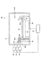
実施例1の基板処置装置10は、図1に示す如く、基板給排部20と、基板保管用バッファ部30と、複数の基板洗浄室40と、基板保管用バッファ部30が有する後述のアウト専用バッファ32に設けた、複数の基板乾燥室60とを有し、基板給排部20と基板保管用バッファ部30の間に搬送ロボット11を設け、基板保管用バッファ部30と基板洗浄室40の間に搬送ロボット12を設けている。
Example 1 (FIGS. 1 to 4)
As shown in FIG. 1, the
基板給排部20は、複数の基板収納カセット21を搬入、搬出可能とされる。基板収納カセット21は、未処理のウェーハや液晶基板等の複数の基板Wを収納されて基板給排部20に搬入されるとともに、基板洗浄室40及び基板乾燥室60で処理された基板Wを収納されて基板給排部20から搬出される。未処理の基板Wは、搬送ロボット11により基板給排部20内の基板収納カセット21において多段をなす各収納棚から順に取出されて基板保管用バッファ部30の後述するイン専用バッファ31(図示せず)に供給され、更に搬送ロボット12により基板保管用バッファ部30のイン専用バッファ31から取出され、基板洗浄室40に供給されて洗浄処理される。基板洗浄室40で洗浄処理された基板Wは搬送ロボット12により基板洗浄室40から取出されて基板保管用バッファ部30の後述するアウト専用バッファ32に投入され、基板保管用バッファ部30のアウト専用バッファ32内の基板乾燥室60で乾燥処理された後に搬送ロボット11により取出され、基板給排部20内の基板収納カセット21の空の収納棚に順に排出される。処理済の基板Wで満杯になった基板収納カセット21が基板給排部20から搬出されるものになる。
The substrate supply /
基板保管用バッファ部30は、未処理の基板Wを保管する複数のイン専用バッファ31が多段をなす棚状に設けられるとともに、基板洗浄室40で洗浄処理された基板Wを保管する複数のアウト専用バッファ32が多段をなす棚状に設けられる。アウト専用バッファ32の内部には基板乾燥室60が後述する如くに設けられている。尚、イン専用バッファ31やアウト専用バッファ32は多段でなくても良い。
The substrate
基板洗浄室40は、図2に示す如く、処理室となる処理ボックス41と、その処理ボックス41内に設けられたカップ42と、そのカップ42内で基板Wを水平状態で支持するテーブル43と、そのテーブル43を水平面内で回転させる回転機構44と、テーブル43の周囲で昇降する溶媒吸引排出部45とを備えている。更に、基板洗浄室40は、テーブル43上の基板Wの表面に薬液を供給する薬液供給部46と、テーブル43上の基板Wの表面に洗浄液を供給する洗浄液供給部47と、揮発性溶媒を供給する溶媒供給部48と、各部を制御する制御部50を備えている。
As shown in FIG. 2, the
処理ボックス41は基板出し入れ口41Aを周壁の一部に開口している。基板出し入れ口41Aはシャッタ41Bにより開閉される。
In the
カップ42は、円筒形状に形成されており、テーブル43を周囲から囲んで内部に収容する。カップ42の周壁の上部は斜め上向きに縮径しており、テーブル43上の基板Wが上方に向けて露出するように開口している。このカップ42は、回転する基板Wから流れ落ちた或いは飛散した薬液、洗浄液を受け取る。尚、カップ42の底部には、受け取った薬液、洗浄液を排出するための排出管(図示せず)が設けられている。
The
テーブル43は、カップ42の中央付近に位置付けられ、水平面内で回転可能に設けられている。このテーブル43は、ピン等の支持部材43Aを複数有しており、これらの支持部材43Aにより、ウェーハや液晶基板等の基板Wを脱着可能に保持する。
The table 43 is positioned near the center of the
回転機構44は、テーブル43に連結された回転軸やその回転軸を回転させる駆動源となるモータ(いずれも図示せず)等を有しており、モータの駆動により回転軸を介してテーブル43を回転させる。この回転機構44は制御部50に電気的に接続されており、その駆動が制御部50により制御される。
The
溶媒吸引排出部45は、テーブル43の周囲を囲んで環状に開口する溶媒吸引口45Aを備える。溶媒吸引排出部45は溶媒吸引口45Aを昇降する昇降機構(図示せず)を有し、テーブル43のテーブル面より下位に溶媒吸引口45Aを位置付ける待機位置と、テーブル43に保持された基板Wの周囲に溶媒吸引口45Aを位置付ける作業位置とに、溶媒吸引口45Aを昇降する。溶媒吸引口45Aは、回転する基板W上から飛散した揮発性溶媒を吸引して受け取る。尚、溶媒吸引口45Aには、揮発性溶媒を吸引するための排気ファン又はバキュームポンプ(図示せず)、及び吸引して受け取った揮発性溶媒を排出するための排出管(図示せず)が接続されている。
The solvent suction /
薬液供給部46は、テーブル43上の基板Wの表面に対して斜め方向から薬液を吐出するノズル46Aを有しており、このノズル46Aからテーブル43上の基板Wの表面に薬液、例えばレジスト剥離処理用のAPM(アンモニア水及び過酸化水素水の混合液)を供給する。ノズル46Aはカップ42の周壁の上部に装着されており、その角度や吐出流速等は基板Wの表面中心付近に薬液が供給されるように調整されている。この薬液供給部46は制御部50に電気的に接続されており、その駆動が制御部50により制御される。尚、薬液供給部46は、薬液を貯留するタンクや駆動源となるポンプ、供給量を調整する調整弁となるバルブ(いずれも図示せず)等を備えている。
The chemical
洗浄液供給部47は、テーブル43上の基板Wの表面に対して斜め方向から洗浄液を吐出するノズル47Aを有しており、このノズル47Aからテーブル43上の基板Wの表面に洗浄液、例えば洗浄処理用の純水(超純水)を供給する。ノズル47Aはカップ42の周壁の上部に装着されており、その角度や吐出流速等は基板Wの表面中心付近に薬液が供給されるように調整されている。この洗浄液供給部47は制御部50に電気的に接続されており、その駆動が制御部50により制御される。尚、洗浄液供給部47は、洗浄液を貯留するタンクや駆動源となるポンプ、供給量を調整する調整弁となるバルブ(いずれも図示せず)等を備えている。
The cleaning
溶媒供給部48は、テーブル43上の基板Wの表面に対して斜め方向から揮発性溶媒を吐出するノズル48Aを有しており、このノズル48Aからテーブル43上の基板Wの表面に揮発性溶媒、例えばIPAを供給する。この溶媒供給部48は洗浄液供給部47によって供給された洗浄液で洗浄された基板Wの表面に揮発性溶媒を供給し、基板Wの表面の洗浄液を揮発性溶媒に置換する。ノズル48Aはカップ42の周壁の上部に装着されており、その角度や吐出流速等は基板Wの表面中心付近に揮発性溶媒が供給されるように調整されている。この溶媒供給部48は制御部50に電気的に接続されており、その駆動が制御部50により制御される。尚、溶媒供給部48は、揮発性溶媒を貯留するタンクや駆動源となるポンプ、供給量を調整する調整弁となるバルブ(いずれも図示せず)等を備えている。
The
ここで、揮発性溶媒としては、IPA以外にも、例えば、エタノール等の1価のアルコール類、また、ジエチルエーテルやエチルメチルエーテル等のエーテル類、更に、炭酸エチレン等を用いることが可能である。尚、揮発性溶媒は、水に可溶であることが好ましい。 Here, in addition to IPA, for example, monovalent alcohols such as ethanol, ethers such as diethyl ether and ethyl methyl ether, ethylene carbonate, and the like can be used as the volatile solvent. . The volatile solvent is preferably soluble in water.
制御部50は、各部を集中的に制御するマイクロコンピュータと、基板処理に関する基板処理情報や各種プログラム等を記憶する記憶部とを備えている。この制御部50は、基板処理情報や各種プログラムに基づいて回転機構44や溶媒吸引排出部45、薬液供給部46、洗浄液供給部47、溶媒供給部48等を制御し、回転中のテーブル43上の基板Wの表面に対し、薬液供給部46による薬液の供給、洗浄液供給部47による洗浄液の供給、溶媒供給部48による揮発性溶媒の供給等の制御を行なう。
The
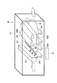
基板乾燥室60は、基板保管用バッファ部30のアウト専用バッファ32において多段をなす各棚毎に設けられ、図3に示す如く、処理室となるトンネル状の処理ボックス61と、その処理ボックス61内において搬送手段を構成する複数の搬送ローラ62とを備えている。更に、基板乾燥室60は、搬送ローラ62上の基板Wの表面にガスを供給するガス供給部63と、基板洗浄室40において揮発性溶媒が供給された基板Wを加熱する加熱手段64と、加熱手段64によって加熱された基板Wの表面を乾燥するための吸引乾燥手段65と、各部を制御する制御部70とを備えている。尚、吸引乾燥手段65が配置された位置より下流側にも搬送ローラ62は設けられるが、図3では省略した。
The
処理ボックス61はトンネル状をなし、搬送ロボット12により基板洗浄室40から取り出された洗浄処理済の基板Wが上流側の開口から投入され、基板乾燥室60による乾燥処理済の基板Wが搬送ロボット11により処理ボックス61の下流側の開口から排出される。
The
搬送ローラ62はモータ等の駆動手段(図示せず)により回転駆動され、処理ボックス61の上流側開口から投入された基板Wをガス供給部63、加熱手段64、吸引乾燥手段65の下方搬送路に沿って下流側開口の側へと搬送する。この搬送ローラ62は制御部70に電気的に接続されており、その駆動が制御部70により制御される。
The
ガス供給部63は、搬送ローラ62による基板搬送方向に沿う加熱手段64の上流側にて、搬送ローラ62の上方に設けられる。ガス供給部63は、搬送ローラ62上の基板Wの表面の幅方向全域に対して斜め方向からガスを吐出するスリット状のノズル63Aを有しており、このノズル63Aから搬送ローラ62上の基板Wの表面にガス、例えば窒素ガスを供給し、処理ボックス61内で基板Wの表面上の空間を窒素ガス雰囲気にする。ノズル63Aは処理ボックス61に装着されており、その角度や吐出流速等は基板Wの表面の幅方向全域にガスが供給されるように調整されている。このガス供給部63は制御部70に電気的に接続されており、その駆動が制御部70により制御される。尚、ガス供給部63は、ガスを貯留するタンクや供給量を調整する調整弁となるバルブ(いずれも図示せず)等を備えている。また、基板Wの表面に既に供給されている揮発性溶媒が、ノズル63Aから吐出するガスで乾燥してしまわないように、その供給量は調整される。
The
ここで、供給するガスとしては、窒素ガス以外の不活性ガス、例えばアルゴンガスや二酸化炭素ガス、ヘリウムガス等を用いることが可能である。この不活性ガスが基板Wの表面に供給されるため、基板Wの表面上の酸素を除去し、ウォーターマーク(水シミ)の生成を防ぐことが可能となる。 Here, as the gas to be supplied, an inert gas other than nitrogen gas, for example, argon gas, carbon dioxide gas, helium gas, or the like can be used. Since this inert gas is supplied to the surface of the substrate W, oxygen on the surface of the substrate W can be removed, and generation of a watermark (water stain) can be prevented.
加熱手段64は、複数のランプ64Aを有しており、搬送ローラ62の上方に設けられ、各ランプ64Aの点灯により搬送ローラ62上の基板Wの表面に光を照射する。加熱手段64は、処理ボックス61に装着されるランプケース64B内に配置したランプ64Aの光を透明カバー64Cから基板Wの表面の幅方向全域に照射して基板Wを加熱する。この加熱手段64は制御部70に電気的に接続されており、その駆動が制御部70により制御される。
The heating means 64 has a plurality of
ここで、加熱手段64としては、例えば直管タイプのランプ64Aを複数本並列に設けたものや電球タイプのランプ64Aを複数個アレイ状に設けたものを用いることが可能である。また、ランプ64Aとしては、例えばハロゲンランプやキセノンフラッシュランプ等を用いることが可能である。
Here, as the heating means 64, for example, a plurality of straight
加熱手段64を用いた基板Wの加熱工程では、その加熱手段64による加熱によって、図8(A)に示すように、基板Wの表面上のパターンPに接触している揮発性溶媒の液体A1が他の部分の揮発性溶媒の液体A1よりも早く気化を始める。つまり、基板Wの表面に供給された揮発性溶媒の液体A1のうち、基板Wの表面に接触している部分のみが気相になるように急速加熱される。これにより、基板Wの表面上のパターンPの周囲には、揮発性溶媒の液体A1の気化(沸騰)によりガスの層(気泡の集合)、即ち、揮発性溶媒の気層A2が薄膜のように形成される。このため、隣り合うパターンPの間の揮発性溶媒の液体A1はその気層A2によって基板Wの表面に押し出されながら自らの表面張力で多数の液玉になる。
In the step of heating the substrate W using the
吸引乾燥手段65は搬送ローラ62による基板搬送方向に沿う加熱手段64の下流側にて、搬送ローラ62の上方に設けられる。吸引乾燥手段65は、処理ボックス61に装着され、搬送ローラ62上の基板Wの表面の幅方向全域に向けてスリット状に開口する溶媒吸引口65Aを備える。吸引乾燥手段65は溶媒吸引口65Aに付与される吸引力を基板Wの表面の幅方向全域に及ぼし、加熱手段64による加熱作用で前述の如くに基板Wの表面に生成された揮発性溶媒の液玉を吸引して除去し、基板Wの表面を乾燥する。この吸引乾燥手段65は制御部70に電気的に接続されており、その駆動が制御部70により制御される。尚、溶媒吸引口65Aには、揮発性溶媒の液玉を吸引するためのバキュームポンプ(図示せず)が接続されている。
The suction drying means 65 is provided above the
基板乾燥室60では、吸引乾燥手段65に加えて吹飛ばし乾燥手段を併用しても良い。この吹飛ばし乾燥手段は、基板Wの表面に生成された上述の揮発性溶媒の液玉を噴射ガスにより吹飛ばして除去し、基板Wの表面を乾燥する。前述のガス供給部63をこの吹飛ばし乾燥手段として兼用することもできる。
In the
尚、図4は、基板乾燥室60の変形例を示すものであり、処理ボックス61内で基板Wの表面上の空間が雰囲気形成手段(図示せず)により窒素ガス雰囲気に制御されているとき、搬送ローラ62における基板搬送方向に沿う加熱手段64の下流側に窒素ガス等の不活性ガスを噴射する吹飛ばし乾燥手段67を設け、この吹飛ばし乾燥手段67によって基板Wの表面に生成される揮発性溶媒の液玉を吹飛ばし除去するようにしたものである。
FIG. 4 shows a modified example of the
制御部70は、各部を集中的に制御するマイクロコンピュータと、基板処理に関する基板処理情報や各種プログラム等を記憶する記憶部とを備えている。この制御部70は、基板処理情報や各種プログラムに基づいてガス供給部63、加熱手段64、吸引乾燥手段65等を制御し、搬送ローラ62上の基板Wの表面に対し、ガス供給部63によるガスの供給、加熱手段64による加熱、吸引乾燥手段65による吸引力等の制御を行なう。
The
以下、基板処理装置10による基板Wの洗浄及び乾燥処理手順について説明する。
(1)搬送ロボット11が基板給排部20の基板収納カセット21から基板保管用バッファ部30のイン専用バッファ31に供給した基板Wを搬送ロボット12により取り出し、この基板Wを基板洗浄室40のテーブル43上にセットした状態で、基板洗浄室40の制御部50は回転機構44を制御し、テーブル43を所定の回転数で回転させ、次いで、溶媒吸引排出部45を待機位置に位置付けた状態で、薬液供給部46を制御し、回転するテーブル43上の基板Wの表面にノズル46Aから薬液、即ちAPMを所定時間供給する。
薬液としてのAPMは、ノズル46Aから、回転するテーブル43上の基板Wの中央に向けて吐出され、基板Wの回転による遠心力によって基板Wの表面全体に広がっていく。これにより、テーブル43上の基板Wの表面はAPMにより覆われて処理されることになる。
Hereinafter, a procedure for cleaning and drying the substrate W by the
(1) The substrate W supplied from the
APM as a chemical solution is discharged from the
尚、制御部50はテーブル43を上述(1)から後述(3)まで継続して回転させる。このとき、テーブル43の回転数や所定時間等の処理条件は予め設定されているが、操作者によって任意に変更可能である。
The
(2)次に、制御部50は、薬液の供給を停止されてから、洗浄液供給部47を制御し、回転するテーブル43上の基板Wの表面にノズル47Aから洗浄液、即ち超純水を所定時間供給する。洗浄液としての超純水は、ノズル47Aから、回転するテーブル43上の基板Wの中央に向けて吐出され、基板Wの回転による遠心力によって基板Wの表面全体に広がっていく。これにより、テーブル43上の基板Wの表面は超純水により覆われて洗浄されることになる。
(2) Next, after the supply of the chemical liquid is stopped, the
(3)次に、制御部50は、洗浄液供給部47による基板Wの洗浄が終了すると、溶媒吸引排出部45を作業位置に位置付け、溶媒供給部48を制御し、回転するテーブル43上の基板Wの表面にノズル48Aから揮発性溶媒、即ちIPAを所定時間供給する。尚、IPAの供給は、上述(2)による超純水が乾燥する前に行なうことが好ましい。揮発性溶媒としてのIPAは、ノズル48Aから、回転するテーブル43上の基板Wの中央に向けて吐出され、基板Wの回転による遠心力によって基板Wの表面全体に広がっていく。このとき、回転する基板W上から飛散するIPAは溶媒吸引排出部45に吸引される。これにより、テーブル43上の基板Wの表面は超純水からIPAに置換されることになる。尚、このときのテーブル43、即ち基板Wの回転数は、基板Wの表面が露出しない程度に、揮発性溶媒の膜が基板Wの表面上で薄膜となるように設定されている。
(3) Next, when the cleaning of the substrate W by the cleaning
また、溶媒供給部48のノズル48Aから吐出されるIPAの温度はその沸点未満とされ、IPAを確実に液体の状態として基板Wの表面に供給するものとすることにより、基板Wの表面の全域において超純水が確実にIPAに均等に置換されるようにする。
Further, the temperature of the IPA discharged from the
(4)次に、制御部50は、基板洗浄室40のテーブル43の回転を停止させ、回転停止されたテーブル43上の基板Wを搬送ロボット12が基板洗浄室40より取り出し、この基板Wを基板保管用バッファ部30のアウト専用バッファ32に設けた基板乾燥室60における処理ボックス61の上流側開口から搬送ローラ62上に投入する。基板乾燥室60の制御部70は、ガス供給部63を制御し、搬送ローラ62上の基板Wの表面にノズル63Aからガス、即ち窒素ガスを所定時間供給する。窒素ガスは、ノズル63Aから、搬送ローラ62上の基板Wの幅方向全域に向けて吐出される。これにより、搬送ローラ62上の基板Wを包む空間は窒素雰囲気となる。この空間を窒素雰囲気にすることで、酸素濃度を減少させて、基板Wの表面におけるウォーターマークの発生を抑止することができる。
(4) Next, the
(5)次に、制御部70は、加熱手段64を制御し、加熱手段64の各ランプ64Aを点灯して、搬送ローラ62上の基板Wを所定時間加熱する。このとき、加熱手段64は、基板Wの温度が10秒で100度以上になることを可能にする加熱を行なうことができる。これにより、基板Wの表面上のパターンPに接触している揮発性溶媒の液体A1を瞬時に気化させ、基板Wの表面上における他の部分の揮発性溶媒の液体A1を直ちに液玉化させることが可能となる。
(5) Next, the
ここで、加熱手段64による加熱乾燥では、基板WのパターンPに接触している揮発性溶媒たるIPAを瞬時に気化させるため、数秒で数百度の高温まで基板Wを加熱することが重要である。またIPAは加熱せず、基板Wだけを加熱することも必要である。このためには、波長500〜3000nmにピーク強度を有するランプ64Aを用いることが望ましい。また、パターン倒壊率を極めて低くできる確実な乾燥のためには、基板Wの最終温度(加熱による到達する最終温度)は、処理液や溶媒の大気圧における沸点よりも20℃以上高めの加熱温度であることが望ましく、加えて、最終温度に達する時間が10秒以内、例えば、数10msec〜数秒の範囲内であることが望ましい。
Here, in the heat drying by the heating means 64, it is important to heat the substrate W to a high temperature of several hundred degrees in a few seconds in order to instantly vaporize the volatile solvent IPA that is in contact with the pattern P of the substrate W. . Also, it is necessary to heat only the substrate W without heating the IPA. For this purpose, it is desirable to use a
(6)次に、制御部70は、吸引乾燥手段65を制御し、搬送ローラ62上にて加熱手段64による加熱作用で基板Wの表面に生成されたIPAの液玉を吸引して除去し、基板Wの表面を乾燥する。
(6) Next, the
(7)次に、搬送ロボット11により基板保管用バッファ部30のアウト専用バッファ32に設けた基板乾燥室60における処理ボックス61の下流側開口から、搬送ローラ62上にて洗浄及び乾燥済となっている基板Wを取り出し、この基板Wを基板給排部20の基板収納カセット21に排出する。
(7) Next, the
本実施例によれば以下の作用効果を奏する。
(a)加熱手段64による基板Wの加熱作用により、基板Wの表面上のパターンPの周囲で置換済の揮発性溶媒たるIPAの液体が気化し、これにより、基板Wの表面上のパターンPの周囲にはIPAが気化した気層が薄膜のように形成される。このため、基板Wの隣り合うパターンPの間のIPAの液体は気層によって押し出されながら、自らの表面張力で多数の液玉になる。このようにして基板Wの表面に生成されたIPAの液玉は、吸引乾燥手段65によって基板Wの表面から直ちに吸引されて除去される。従って、基板Wの全表面でIPAの液体を瞬時に乾燥されることができ、基板Wの表面の各部の乾燥速度を均一にする結果、一部のパターンPの間にIPAの残留を生じることがなく、そのような残留IPAの液体の表面張力によるパターンPの倒壊を抑止できる。
According to the present embodiment, the following operational effects can be obtained.
(a) Due to the heating action of the substrate W by the heating means 64, the IPA liquid as a volatile solvent that has been replaced around the pattern P on the surface of the substrate W is vaporized. A gas layer in which IPA is vaporized is formed like a thin film around. For this reason, the IPA liquid between the adjacent patterns P of the substrate W becomes a large number of liquid balls by its own surface tension while being pushed out by the gas layer. The liquid balls of IPA generated on the surface of the substrate W in this way are immediately sucked and removed from the surface of the substrate W by the suction drying means 65. Therefore, the IPA liquid can be instantly dried on the entire surface of the substrate W, and as a result of uniforming the drying speed of each part of the surface of the substrate W, the IPA remains between some patterns P. Therefore, the collapse of the pattern P due to the surface tension of the liquid of such residual IPA can be suppressed.
(b)吸引乾燥手段65により揮発性溶媒たるIPAを確実かつ容易に特定の専用排出先に吸引して除去できる。従って、揮発性溶媒が排出先で他の薬液と接触する等を回避し、揮発性溶媒の不測の発火等を防止できる。 (b) The suction drying means 65 can reliably and easily suck and remove IPA as a volatile solvent to a specific dedicated discharge destination. Accordingly, it is possible to prevent the volatile solvent from coming into contact with other chemicals at the discharge destination, and to prevent unexpected ignition of the volatile solvent.
(c)上述(a)の吸引乾燥手段65に加えて、吹飛ばし乾燥手段(ガス供給部63又は吹飛ばし乾燥手段67)を用いることにより、基板Wの表面に生成された揮発性溶媒の液玉を吹飛ばして除去できる。基板Wの表面上の揮発性溶媒の液体を一層瞬時に乾燥させ、基板表面の各部の乾燥速度を一層均一にし、基板表面上のパターンPの倒壊を一層確実に抑止できる。
(c) The liquid of the volatile solvent generated on the surface of the substrate W by using the blowing drying means (the
(実施例2)(図5)
実施例2の基板処理装置100は、実施例1の基板処理装置10における基板洗浄室40を基板処理室110とし、実施例1の基板保管用バッファ部30のアウト専用バッファ32から基板乾燥室60を撤去し、実施例1の基板洗浄室40と基板乾燥室60の機能を基板処理室110に集約したことにある。以下、基板処理室110について説明する。
(Example 2) (FIG. 5)
The
基板洗浄室110は、図5に示す如く、処理室となる処理ボックス111と、その処理ボックス111内に設けられたカップ112と、そのカップ112内で基板Wを水平状態で支持するテーブル113と、そのテーブル113を水平面内で回転させる回転機構114と、テーブル113の周囲で昇降する溶媒吸引排出部115とを備えている。更に、基板洗浄室110は、テーブル113上の基板Wの表面に薬液を供給する薬液供給部116と、テーブル113上の基板Wの表面に洗浄液供給部117と、揮発性溶媒を供給する溶媒供給部118と、ガスを供給するガス供給部119と、揮発性溶媒が供給された基板Wを加熱する加熱手段121と、各部を制御する制御部130とを備えている。
As shown in FIG. 5, the
基板処理室110において、処理ボックス111、カップ112、テーブル113、回転機構114、溶媒吸引排出部115、薬液供給部116、洗浄液供給部117、溶媒供給部118の各部の具体的構成は、実施例1の基板洗浄室40に設けた処理ボックス41、カップ42、テーブル43、回転機構44、溶媒吸引排出部45、薬液供給部46、洗浄液供給部47、溶媒供給部48におけると同様である。
In the
但し、基板処理室110において、溶媒吸引排出部115は、回転する基板W上から飛散した揮発性溶媒を吸引して受け取るだけでなく、加熱手段121による加熱作用で基板Wの表面に生成された揮発性溶媒の液玉を基板Wの表面上から吸引除去する点で溶媒吸引排出部45にない機能ももつ。従って、溶媒吸引排出部115は、基板Wの表面に存在するIPAなどの揮発性溶媒の液玉を吸引する程度の吸引力を有するものとされる。
However, in the
ガス供給部119は、テーブル113上の基板Wの表面に対して斜め方向からガスを吐出するノズル119Aを有しており、このノズル119Aからテーブル113上の基板Wの表面に不活性ガス、例えば窒素ガスを供給し、処理ボックス111内で基板Wの表面上の空間を窒素ガス雰囲気にする。ガス供給部119の具体的構成は、実施例1の基板乾燥室60に設けたガス供給部63におけると同様である。尚、ノズル119Aはスリット状である必要はなく、円形ノズルであっても良い。
The
加熱手段121は、複数のランプ121Aを有しており、テーブル113の上方に設けられ、各ランプ121Aの点灯によりテーブル113上の基板Wの表面に光を照射する。この加熱手段121は移動機構121Bにより上下方向(昇降方向)に移動可能に構成されており、カップ112に近接した照射位置(図5中の実線で示すように、基板Wの表面に近接した位置)とカップ112から所定距離だけ離間した待機位置(図5中の一点鎖線で示すように、基板Wの表面から離間した位置)とに移動する。基板Wに薬液や洗浄液を供給するとき、加熱手段121を待機位置に位置付けておくことで、処理に用いる液体が加熱手段121に付着することが防止される。また、基板処理室110のテーブル113に基板Wがセットされるとき、加熱手段121を待機位置に位置付けておくことで、加熱手段121が基板Wの搬入の邪魔になることが回避される。加熱手段121は、ランプ点灯後下降、下降後ランプ点灯のどちらでも良い。加熱手段121の具体的構成は、実施例1の基板乾燥室60に設けた加熱手段64におけると同様である。
The
加熱手段121を用いた基板Wの加熱工程では、その加熱手段121による加熱によって、実施例1の加熱手段64におけると同様にして図8(A)に示すように、基板Wの表面上のパターンPに接触している揮発性溶媒の液体A1が他の部分の揮発性溶媒の液体A1よりも早く気化を始める。つまり、基板Wの表面に供給された揮発性溶媒の液体A1のうち、基板Wの表面に接触している部分のみが気相になるように急速加熱される。これにより、基板Wの表面上のパターンPの周囲には、揮発性溶媒の液体A1の気化(沸騰)によりガスの層(気泡の集合)、即ち、揮発性溶媒の気層A2が薄膜のように形成される。このため、隣り合うパターンPの間の揮発性溶媒の液体A1はその気層A2によって基板Wの表面に押し出されながら自らの表面張力で多数の液玉になる。 In the heating process of the substrate W using the heating means 121, the pattern on the surface of the substrate W is heated by the heating means 121 as shown in FIG. 8A in the same manner as in the heating means 64 of the first embodiment. The volatile solvent liquid A1 in contact with P starts to vaporize earlier than the volatile solvent liquid A1 in other parts. In other words, in the volatile solvent liquid A1 supplied to the surface of the substrate W, only the portion in contact with the surface of the substrate W is rapidly heated so as to be in a gas phase. Thereby, around the pattern P on the surface of the substrate W, a gas layer (a collection of bubbles) due to vaporization (boiling) of the liquid A1 of the volatile solvent, that is, the gas layer A2 of the volatile solvent seems to be a thin film. Formed. For this reason, the liquid A1 of the volatile solvent between the adjacent patterns P becomes a large number of liquid balls by its surface tension while being pushed out to the surface of the substrate W by the gas layer A2.
以下、基板処理装置100による基板Wの洗浄及び乾燥処理手順について説明する。
(1)搬送ロボット11が基板給排部20の基板収納カセット21から基板保管用バッファ部30のイン専用バッファ31に供給した基板Wを搬送ロボット12により取り出し、この基板Wを基板処理室110のテーブル113上にピン等の支持部材113Aにより保持してセットした状態で、実施例1の基板処理装置10におけると同様にして、基板処理室110の制御部130は回転機構114を制御し、テーブル113を所定の回転数で回転させ、次いで、溶媒吸引排出部115を待機位置に位置付けた状態で、薬液供給部116を制御し、回転するテーブル113上の基板Wの表面にノズル116Aから薬液、即ちAPMを所定時間供給する。
Hereinafter, procedures for cleaning and drying the substrate W by the
(1) The substrate W supplied by the
(2)次に、制御部130は、実施例1の基板処理装置10におけると同様にして、薬液の供給を停止されてから、洗浄液供給部117を制御し、回転するテーブル113上の基板Wの表面にノズル117Aから洗浄液、即ち超純水を所定時間供給する。
(2) Next, similarly to the
(3)次に、制御部130は、洗浄液供給部117による基板Wの洗浄が終了すると、溶媒吸引排出部115を作業位置に位置付け、実施例1の基板処理装置10におけると同様にして、溶媒供給部118を制御し、回転するテーブル113上の基板Wの表面にノズル118Aから揮発性溶媒、即ちIPAを所定時間供給するとともに、回転する基板W上から飛散するIPAが溶媒吸引排出部115に吸引される。これにより、テーブル113上の基板Wの表面は超純水からIPAに置換されることになる。
(3) Next, when the cleaning
(4)次に、制御部130は、ガス供給部119を制御し、回転するテーブル113上の基板Wの表面にノズル119Aからガス、即ち窒素ガス等の不活性ガスを所定時間供給する。
(4) Next, the
(5)次に、制御部130は、上述(3)によるIPAへの置換が終了すると、加熱手段121を制御し、今まで待機位置にあった加熱手段121を照射位置に位置付け、加熱手段121の各ランプ121Aを点灯して、回転するテーブル113上の基板Wを所定時間加熱する。
(5) Next, when the replacement with the IPA according to the above (3) is completed, the
ここで、加熱手段121による加熱乾燥では、基板WのパターンPに接触している揮発性溶媒たるIPAを瞬時に気化させるため、数秒で数百度の高温まで基板Wを加熱することが重要である。またIPAは加熱せず、基板Wだけを加熱することも必要である。このためには、波長500〜3000nmにピーク強度を有するランプ121Aを用いることが望ましい。また、確実な乾燥のためには、基板Wの最終温度(加熱による到達する最終温度)は、処理液や溶媒の大気圧における沸点よりも20℃以上高めの加熱温度であることが望ましく、加えて、最終温度に達する時間が10秒以内、例えば、数10msec〜数秒の範囲内であることが望ましい。
Here, in the heat drying by the heating means 121, it is important to heat the substrate W up to a high temperature of several hundred degrees in a few seconds in order to instantaneously vaporize the IPA that is a volatile solvent in contact with the pattern P of the substrate W. . Also, it is necessary to heat only the substrate W without heating the IPA. For this purpose, it is desirable to use a
(6)加熱手段121による加熱作用で、基板Wの表面にはIPAの液玉が生成される。このとき溶媒吸引口115Aには、前述のように基板Wの表面に存在するIPAの液玉を吸引し得る程度の吸引力が付与されているから、生成されたIPAの液玉は、溶媒吸引口115Aを経由して吸引され除去される。これにより乾燥が終了する。尚、この加熱手段121によって基板Wを加熱する時、基板を回転させたが、回転させなくても良い。基板を回転させた場合、基板Wの表面に生成された液玉の一部は、基板Wの回転による遠心力で溶媒吸引排出部115に到達し、溶媒吸引排出部115に吸引されて除去される。従って、本実施例では、回転テーブル113、回転機構114は、加熱手段121による加熱作用で基板の表面に生成された揮発性溶媒の液玉を基板Wの回転により振り切って除去し、基板Wの表面を乾燥する基板回転乾燥手段を構成する。また、溶媒吸引排出部115は、加熱手段121による加熱作用で基板の表面に生成された揮発性溶媒の液玉を吸引して除去し、基板の表面を乾燥する、吸引乾燥手段を構成する。
(6) Due to the heating action by the heating means 121, IPA liquid balls are generated on the surface of the substrate W. At this time, the
(7)次に、制御部130は、テーブル113の回転を停止させ、回転停止されたテーブル113上にて洗浄及び乾燥済となっている基板Wを搬送ロボット12が基板処理室110より取り出し、この基板Wを基板保管用バッファ部30のアウト専用バッファ32に投入する。搬送ロボット11は、この基板Wを基板保管用バッファ部30のアウト専用バッファ32から取り出し、基板給排部20の基板収納カセット21に排出する。
(7) Next, the
尚、上述(7)の基板Wの取り出し前に、制御部130は、加熱手段121のランプ121Aを消灯させ、かつ待機位置に位置付ける。これにより、基板Wの取り出し時に加熱手段121が邪魔にならない。
Before taking out the substrate W in (7) above, the
従って、実施例2の基板処理装置100にあっても、実施例1の基板処理装置10におけると実質的に同様の作用効果を奏する。尚、この実施例2において、上述した手順(4)と(5)は順番を逆にしても良い。
Therefore, the
(実施例3)(図6、図7)
実施例3の基板処置装置200は、基板処理室210となるトンネル状の処理ボックス211と、その処理ボックス211内において搬送手段を構成して基板Wを搬送する複数の搬送ローラ212とを備えている。更に、基板処理装置200は、搬送ローラ212上の基板Wの表面に薬液を供給する薬液供給部213と、搬送ローラ212上の基板Wの表面に洗浄液を供給する洗浄液供給部214と、揮発性溶媒を供給する溶媒供給部215と、搬送ローラ212上の基板Wの表面にガスを供給するガス供給部216と、揮発性溶媒が供給された基板Wを加熱する加熱手段217と、加熱手段217によって加熱された基板Wの表面を乾燥するための吸引乾燥手段218と、各部を制御する制御部220とを備えている。
Example 3 (FIGS. 6 and 7)
The
処理ボックス211はトンネル状をなし、未処理の基板Wが上流側の開口から投入され、基板処理室210による洗浄及び乾燥処理済の基板Wを処理ボックス211の下流側の開口から排出する。
The
搬送ローラ212はモータ等の駆動手段(図示せず)により回転駆動され、処理ボックス211の上流側開口から投入された基板Wを薬液供給部213、洗浄液供給部214、溶媒供給部215、ガス供給部216、加熱手段217、吸引乾燥手段218の下方搬送路に沿って下流側開口の側へと搬送する。この搬送ローラ212は制御部220に電気的に接続されており、その駆動が制御部220により制御される。尚、図6、図7においては、薬液供給部213、洗浄液供給部214、溶媒供給部215が、基板Wの搬送方向に沿って順次近接して配置されるように示したが、それらの配置間隔は、搬送される基板Wの搬送方向長さより大きなピッチで設定されるとともに、各供給部からの液供給量に応じて適宜設定される。
The
薬液供給部213は、搬送ローラ212上の基板Wの表面の幅方向全域に対して上方から薬液を吐出するスリット状のノズル213Aを有しており、このノズル213Aから搬送ローラ212上の基板Wの表面に薬液、例えばレジスト剥離処理用のAPM(アンモニア水及び過酸化水素水の混合液)を供給する。この薬液供給部213は制御部220に電気的に接続されており、その駆動が制御部220により制御される。尚、薬液供給部213は、薬液を貯留するタンクや駆動源となるポンプ、供給量を調整する調整弁となるバルブ(いずれも図示せず)等を備えている。
The chemical
洗浄液供給部214は、搬送ローラ212上の基板Wの表面の幅方向全域に対して上方から洗浄液を吐出するスリット状のノズル214Aを有しており、このノズル214Aから搬送ローラ212上の基板Wの表面に洗浄液、例えば洗浄処理用の純水(超純水)を供給する。この洗浄液供給部214は制御部220に電気的に接続されており、その駆動が制御部220により制御される。尚、洗浄液供給部214は、洗浄液を貯留するタンクや駆動源となるポンプ、供給量を調整する調整弁となるバルブ(いずれも図示せず)等を備えている。
The cleaning
溶媒供給部215は、搬送ローラ212上の基板Wの表面の幅方向全域に対して上方から揮発性溶媒を吐出するスリット状のノズル215Aを有しており、このノズル215Aから搬送ローラ212上の基板Wの表面に揮発性溶媒、例えばIPAを供給する。この溶媒供給部215は洗浄液供給部214によって洗浄液が供給済の基板Wの表面に揮発性溶媒を供給し、基板Wの表面の洗浄液を揮発性溶媒に置換する。この溶媒供給部215は制御部220に電気的に接続されており、その駆動が制御部220により制御される。尚、溶媒供給部215は、揮発性溶媒を貯留するタンクや駆動源となるポンプ、供給量を調整する調整弁となるバルブ(いずれも図示せず)等を備えている。
The
ガス供給部216は、搬送ローラ212による基板搬送方向に沿う加熱手段217の上流側にて、搬送ローラ212の上方に設けられる。ガス供給部216は、搬送ローラ212上の基板Wの表面の幅方向全域に対して斜め方向からガスを吐出するスリット状のノズル216Aを有しており、このノズル216Aから搬送ローラ212上の基板Wの表面にガス、例えば窒素ガス等の不活性ガスを供給し、処理ボックス211内で基板Wの表面上の空間を窒素ガス雰囲気にする。ノズル216Aは処理ボックス211に装着されており、その角度や吐出流速等は基板Wの表面の幅方向全域にガスが供給されるように調整されている。このガス供給部216は制御部220に電気的に接続されており、その駆動が制御部220により制御される。尚、ガス供給部216は、ガスを貯留するタンクや供給量を調整する調整弁となるバルブ(いずれも図示せず)等を備えている。
The
加熱手段217は、複数のランプ217Aを有しており、搬送ローラ212の上方に設けられ、各ランプ217Aの点灯により搬送ローラ212上の基板Wの表面に光を照射する。加熱手段217は、処理ボックス211に装着されるランプケース217B内に配置したランプ217Aの光を透明カバー217Cから基板Wの表面の幅方向全域に照射して基板Wを加熱する。この加熱手段217は制御部220に電気的に接続されており、その駆動が制御部220により制御される。
The
加熱手段217を用いた基板Wの加熱工程では、その加熱手段217による加熱によって、図8(A)に示すように、基板Wの表面上のパターンPに接触している揮発性溶媒の液体A1が他の部分の揮発性溶媒の液体A1よりも早く気化を始める。これにより、基板Wの表面上のパターンPの周囲には、揮発性溶媒の液体A1の気化(沸騰)によりガスの層(気泡の集合)、即ち、揮発性溶媒の気層A2が薄膜のように形成される。このため、隣り合うパターンPの間の揮発性溶媒の液体A1はその気層A2によって基板Wの表面に押し出されながら自らの表面張力で多数の液玉になる。 In the heating process of the substrate W using the heating means 217, the volatile solvent liquid A1 that is in contact with the pattern P on the surface of the substrate W as shown in FIG. Starts to vaporize earlier than the other part of the volatile solvent liquid A1. Thereby, around the pattern P on the surface of the substrate W, a gas layer (a collection of bubbles) due to vaporization (boiling) of the liquid A1 of the volatile solvent, that is, the gas layer A2 of the volatile solvent seems to be a thin film. Formed. For this reason, the liquid A1 of the volatile solvent between the adjacent patterns P becomes a large number of liquid balls by its surface tension while being pushed out to the surface of the substrate W by the gas layer A2.
吸引乾燥手段218は搬送ローラ212による基板搬送方向に沿う加熱手段217の下流側にて、搬送ローラ212の上方に設けられる。吸引乾燥手段218は、処理ボックス211に装着され、搬送ローラ212上の基板Wの表面の幅方向全域に向けてスリット状に開口する溶媒吸引口218Aを備える。吸引乾燥手段218は溶媒吸引口218Aに付与される吸引力を基板Wの表面の幅方向全域に及ぼし、加熱手段217による加熱作用で前述の如くに基板Wの表面に生成された揮発性溶媒の液玉を吸引して除去し、基板Wの表面を乾燥する。この吸引乾燥手段218は制御部220に電気的に接続されており、その駆動が制御部220により制御される。尚、溶媒吸引口218Aには、揮発性溶媒の液玉を吸引するためのバキュームポンプ(図示せず)が接続されている。
The
基板処理室210では、吸引乾燥手段218に加えて吹飛ばし乾燥手段を併用しても良い。この吹飛ばし乾燥手段は、基板Wの表面に生成された上述の揮発性溶媒の液玉を噴射ガスにより吹飛ばして除去し、基板Wの表面を乾燥する。前述のガス供給部216をこの吹飛ばし乾燥手段として兼用することもできる。
In the
尚、図7は、基板処理室210の変形例を示すものであり、処理ボックス211内で基板Wの表面上の空間が雰囲気形成手段(図示せず)により窒素ガス雰囲気に制御されているとき、搬送ローラ212における基板搬送方向に沿う加熱手段217の下流側に窒素ガス等の不活性ガスを噴射する吹飛ばし乾燥手段219を設け、この吹飛ばし乾燥手段219によって基板Wの表面に生成される揮発性溶媒の液玉を吹飛ばし除去するようにしたものである。
FIG. 7 shows a modified example of the
以下、基板処理装置200による基板Wの洗浄及び乾燥処理手順について説明する。
(1)基板処理室210における処理ボックス211の上流側開口から搬送ローラ212上に液晶基板等の基板Wが搬入されると、制御部220は、薬液供給部213を制御し、搬送ローラ212上の基板Wの表面の幅方向全域にノズル213Aから薬液、即ちAPMを所定時間供給する。これにより、搬送ローラ212上の基板Wの表面はAPMにより覆われて処理されることになる。
Hereinafter, a procedure for cleaning and drying the substrate W by the
(1) When a substrate W such as a liquid crystal substrate is loaded onto the
(2)次に、制御部220は、薬液の供給を停止されてから、洗浄液供給部214を制御し、搬送ローラ212上の基板Wの表面の幅方向全域にノズル214Aから洗浄液、即ち超純水を所定時間供給する。これにより、搬送ローラ212上の基板Wの表面は超純水により覆われて洗浄されることになる。
(2) Next, after the supply of the chemical liquid is stopped, the
(3)次に、制御部220は、溶媒供給部215を制御し、搬送ローラ212上の基板Wの表面の幅方向全域にノズル215Aから揮発性溶媒、即ちIPAを所定時間供給する。これにより、搬送ローラ212上の基板Wの表面は超純水からIPAに置換されることになる。
(3) Next, the
(4)次に、制御部220は、ガス供給部216を制御し、搬送ローラ212上の基板Wの表面にノズル216Aからガス、即ち窒素ガスを所定時間供給する。窒素ガスは、ノズル216Aから、搬送ローラ212上の基板Wの幅方向全域に向けて吐出される。これにより、搬送ローラ212上の基板Wを包む空間は窒素雰囲気となる。この空間を窒素雰囲気にすることで、酸素濃度を減少させて、基板Wの表面におけるウォーターマークの発生を抑止することができる。
(4) Next, the
(5)次に、制御部220は、加熱手段217を制御し、加熱手段217の各ランプ217Aを点灯して、搬送ローラ212上の基板Wを所定時間加熱する。このとき、加熱手段217は、基板Wの温度が10秒で100度以上になることを可能にする加熱を行なうことができる。これにより、基板Wの表面上のパターンPに接触している揮発性溶媒の液体A1を瞬時に気化させ、基板Wの表面上における他の部分の揮発性溶媒の液体A1を直ちに液玉化させることが可能となる。
(5) Next, the
ここで、加熱手段217による加熱乾燥では、基板WのパターンPに接触している揮発性溶媒たるIPAを瞬時に気化させるため、数秒で数百度の高温まで基板Wを加熱することが重要である。またIPAは加熱せず、基板Wだけを加熱することも必要である。このためには、波長500〜3000nmにピーク強度を有するランプ217Aを用いることが望ましい。また、確実な乾燥のためには、基板Wの最終温度(加熱による到達する最終温度)は、処理液や溶媒の大気圧における沸点よりも20℃以上高めの加熱温度であることが望ましく、加えて、最終温度に達する時間が10秒以内、例えば、数10msec〜数秒の範囲内であることが望ましい。
Here, in the heat drying by the
(6)次に、制御部220は、吸引乾燥手段218を制御し、搬送ローラ212上にて加熱手段217による加熱作用で基板Wの表面に生成されたIPAの液玉を吸引して除去し、基板Wの表面を乾燥する。
(6) Next, the
(7)次に、基板処理室210における処理ボックス211の下流側開口から、搬送ローラ212上にて洗浄及び乾燥済となっている基板Wを取り出し、この基板Wを下流工程に排出する。
(7) Next, the substrate W that has been cleaned and dried on the
本実施例によれば以下の作用効果を奏する。
(a)加熱手段217による基板Wの加熱作用により、基板Wの表面上のパターンPの周囲で置換済の揮発性溶媒たるIPAの液体が気化し、これにより、基板Wの表面上のパターンPの周囲にはIPAが気化した気層が薄膜のように形成される。このため、基板Wの隣り合うパターンPの間のIPAの液体は気層によって押し出されながら、自らの表面張力で多数の液玉になる。このようにして基板Wの表面に生成されたIPAの液玉は、吸引乾燥手段218(吹飛ばし乾燥手段としてのガス供給部216、又は吹飛ばし乾燥手段219を併せ用いることもある)によって基板Wの表面から直ちに吸引されて除去される。従って、基板Wの全表面でIPAの液体を瞬時に乾燥されることができ、基板Wの表面の各部の乾燥速度を均一にする結果、一部のパターンPの間にIPAの残留を生じることがなく、そのような残留IPAの液体の表面張力によるパターンPの倒壊を抑止できる。
According to the present embodiment, the following operational effects can be obtained.
(a) Due to the heating action of the substrate W by the heating means 217, the IPA liquid as a volatile solvent that has been replaced around the pattern P on the surface of the substrate W is vaporized, whereby the pattern P on the surface of the substrate W is vaporized. A gas layer in which IPA is vaporized is formed like a thin film around. For this reason, the IPA liquid between the adjacent patterns P of the substrate W becomes a large number of liquid balls by its own surface tension while being pushed out by the gas layer. The IPA liquid balls generated on the surface of the substrate W in this manner are obtained by the suction drying means 218 (the
(b)吸引乾燥手段218により揮発性溶媒たるIPAを確実かつ容易に特定の専用排出先に吸引して除去できる。従って、揮発性溶媒が排出先で他の薬液と接触する等を回避し、揮発性溶媒の不測の発火等を防止できる。 (b) The suction drying means 218 can reliably and easily suck and remove IPA as a volatile solvent to a specific dedicated discharge destination. Accordingly, it is possible to prevent the volatile solvent from coming into contact with other chemicals at the discharge destination, and to prevent unexpected ignition of the volatile solvent.
(c)上述(a)の吸引乾燥手段218に加えて、吹飛ばし乾燥手段(ガス供給部216又は吹飛ばし乾燥手段219)を用いることにより、基板Wの表面に生成された揮発性溶媒の液玉を吹飛ばして除去できる。基板Wの表面上の揮発性溶媒の液体を一層瞬時に乾燥させ、基板表面の各部の乾燥速度を一層均一にし、基板表面上のパターンPの倒壊を一層確実に抑止できる。尚、吸引乾燥手段218を設けることなく、吹飛ばし乾燥手段(ガス供給部216又は吹飛ばし乾燥手段219)を設け、加熱手段217による基板Wの加熱作用により生じたIPAの液玉を基板上から吹き飛ばすことでIPAの液玉を基板上から排出して基板Wを乾燥させるようにしても良い。この点は、例えば実施例1においても同じことが言える。即ち、図3、図4において、吸引乾燥手段65を設けることなく、吹飛ばし乾燥手段(ガス供給部63又は吹飛ばし乾燥手段67)を設け、加熱手段64による基板Wの加熱作用により生じた揮発性溶媒(IPA等)の液玉を基板上から吹き飛ばすことで、揮発性溶媒の液玉を基板上から排出して基板Wを乾燥させるようにしても良い。尚、吹き飛ばされたIPAの液玉は、処理ボックス61、211の下方に設けた排出部より外部に排出されるようにしておくと良い。
(c) In addition to the suction drying means 218 described in (a) above, the liquid of the volatile solvent generated on the surface of the substrate W by using the blow-off drying means (the
以上、本発明の実施例を図面により詳述したが、本発明の具体的な構成はこの実施例に限られるものではなく、本発明の要旨を逸脱しない範囲の設計の変更等があっても本発明に含まれる。 The embodiment of the present invention has been described in detail with reference to the drawings. However, the specific configuration of the present invention is not limited to this embodiment, and even if there is a design change or the like without departing from the gist of the present invention. It is included in the present invention.
例えば、実施例1においては、基板Wが基板洗浄室40から基板乾燥室60まで搬送される間に基板上の揮発性溶媒が乾燥する恐れもある。そのため、図3、図4に示した基板乾燥室60における処理ボックス61の上流側開口に揮発性溶媒の供給装置を設けておき、基板洗浄室40では洗浄液の供給まで行なった後の基板Wを基板乾燥室60に搬送するとともに、この基板Wを基板乾燥室60に投入するときに、基板W面上に揮発性溶媒を供給するようにしても良い。
For example, in the first embodiment, the volatile solvent on the substrate may be dried while the substrate W is transported from the
また、実施例1や実施例3では、基板Wを搬送ローラ62、212で搬送するようにしたが、ローラに代えて基板Wをクランパで挟んで搬送するものであっても良い。
In the first and third embodiments, the substrate W is transported by the
例えば、実施例3においては、基板Wを搬送させながら、その基板Wに対し、薬液、洗浄液、揮発性溶媒などを順次供給するようにしたが、搬送ローラ212等を用いて基板Wを搬送するとともに、基板の例えば搬送方向中央部が、薬液を吐出するノズル213A、洗浄液を吐出するノズル214A、そして揮発性溶媒を吐出するノズル215Aに対向したところで基板Wの搬送を順次停止させ、この停止している基板Wに対して、各ノズルから薬液などの処理液を供給するようにしても良い。加熱手段217による基板Wの加熱においても同様で、基板Wを停止させた状態で加熱するようにしても良い。
For example, in the third embodiment, while the substrate W is being transported, the chemical solution, the cleaning liquid, the volatile solvent, and the like are sequentially supplied to the substrate W. However, the substrate W is transported using the
実施例1のように、アウト専用バッファ32を多段にし、各段に基板乾燥室60を設ければ、各段での乾燥処理を並行して進めることができるので、基板の処理能力を向上させることができるが、アウト専用バッファ32を多段とせずに1段とし、この段に基板乾燥室を設けるようにしても良い。
If the out-
ガス供給部63、119、216による窒素ガス等の不活性ガスの供給動作は、基板Wがそれぞれの供給位置に位置付けられた後に開始されるようにしたが、位置付けられる前から供給が開始されるようにしても良い。
The supply operation of the inert gas such as nitrogen gas by the
例えば実施例2において、加熱手段121による基板Wの加熱は、処理ボックス111内を減圧した状態で行なうようにしても良い。処理ボックス111内におけるIPAなど揮発性溶媒の沸点が下がり、大気圧下に比べて低い温度で沸騰するので、基板に与える熱ダメージを軽減することができる。
For example, in the second embodiment, the heating of the substrate W by the
各実施例において、基板Wに対する洗浄液の供給が停止してからIPAなどの揮発性溶媒の供給を開始したが、洗浄液による洗浄の終期で、まだ洗浄液が基板Wに対して供給されているときから揮発性溶媒の供給を開始させるようにしても良い。この場合、実施例3においては、洗浄液供給部214と溶媒供給部215の配置間隔を、搬送される基板Wの搬送方向長さより小さな間隔に設定することで実施できる。
In each embodiment, the supply of the volatile solvent such as IPA is started after the supply of the cleaning liquid to the substrate W is stopped, but since the cleaning liquid is still supplied to the substrate W at the end of the cleaning with the cleaning liquid. You may make it start supply of a volatile solvent. In this case, the third embodiment can be implemented by setting the arrangement interval between the cleaning
各実施例において、供給される気体は、加熱された気体とすることもできる。 In each embodiment, the supplied gas may be a heated gas.
各実施例において、IPAなどの揮発性溶媒を基板Wに供給する前に、処理ボックス41、111、211内に乾燥空気又は窒素などの不活性ガスを供給するようにすると好ましい。
In each embodiment, before supplying a volatile solvent such as IPA to the substrate W, it is preferable to supply an inert gas such as dry air or nitrogen into the
本発明によれば、基板の乾燥時に表面上の液体を瞬時に乾燥させる基板処理装置及び基板処理方法を提供することができる。 ADVANTAGE OF THE INVENTION According to this invention, the substrate processing apparatus and substrate processing method which dry the liquid on the surface instantly at the time of drying of a board | substrate can be provided.
10、100、200 基板処理装置
47、117、214 洗浄液供給部
48、118、215 溶媒供給部
64、121、217 加熱手段
65、218 吸引乾燥手段
67、219 吹飛ばし乾燥手段
113 テーブル(基板回転乾燥手段)
W 基板
10, 100, 200
W substrate
Claims (6)
前記洗浄液が供給された前記基板の表面に揮発性溶媒を供給し、前記基板の表面の前記洗浄液を前記揮発性溶媒に置換する溶媒供給部と、
前記揮発性溶媒が供給された前記基板を加熱するランプを有する加熱手段と、
前記加熱手段による加熱作用で前記基板の表面に生成された前記揮発性溶媒の液玉を吸引して前記基板の表面から除去し、前記基板の表面を乾燥する吸引乾燥手段と、
を有し、
前記加熱手段による加熱作用で、前記基板の表面上のパターンの周囲には、前記揮発性溶媒の気化により前記揮発性溶媒の薄膜気層が形成され、これにより、隣り合う前記パターンの間の前記揮発性溶媒の液体は前記気層によって前記基板の表面に押し出されながら多数の液玉になり、この液玉が前記吸引乾燥手段に吸引されることを特徴とする基板処理装置。 A cleaning liquid supply unit for supplying a cleaning liquid to the surface of the substrate;
Supplying a volatile solvent to the surface of the substrate supplied with the cleaning liquid, and replacing the cleaning liquid on the surface of the substrate with the volatile solvent;
Heating means having a lamp for heating the substrate supplied with the volatile solvent;
Suction and drying means for sucking and removing the liquid balls of the volatile solvent generated on the surface of the substrate by the heating action of the heating means to remove from the surface of the substrate and drying the surface of the substrate;
Have
Due to the heating action of the heating means, a thin film gas layer of the volatile solvent is formed around the pattern on the surface of the substrate by vaporization of the volatile solvent, and thereby, the film between the adjacent patterns is formed. The substrate processing apparatus is characterized in that the liquid of the volatile solvent becomes a large number of liquid balls while being pushed out to the surface of the substrate by the gas layer, and the liquid balls are sucked by the suction drying means.
前記洗浄液が供給された前記基板の表面に揮発性溶媒を供給し、前記基板の表面の前記洗浄液を前記揮発性溶媒に置換する工程と、
前記揮発性溶媒が供給された前記基板をランプを用いて加熱する工程と、
前記ランプによる加熱作用で前記基板の表面に生成された前記揮発性溶媒の液玉を吸引して前記基板の表面から除去し、前記基板の表面を乾燥する工程と、
を有し、
前記ランプによる加熱作用で、前記基板の表面上のパターンの周囲には、前記揮発性溶媒の気化により前記揮発性溶媒の薄膜気層が形成され、これにより、隣り合う前記パターンの間の前記揮発性溶媒の液体は前記気層によって前記基板の表面に押し出されながら多数の液玉になり、この液玉が前記乾燥する工程で吸引されて前記基板の表面から除去されることを特徴とする基板処理方法。 Supplying a cleaning liquid to the surface of the substrate;
Supplying a volatile solvent to the surface of the substrate supplied with the cleaning liquid, and replacing the cleaning liquid on the surface of the substrate with the volatile solvent;
Heating the substrate supplied with the volatile solvent using a lamp;
Sucking the liquid balls of the volatile solvent generated on the surface of the substrate by the heating action of the lamp to remove it from the surface of the substrate, and drying the surface of the substrate;
Have
A thin film layer of the volatile solvent is formed by vaporization of the volatile solvent around the pattern on the surface of the substrate by the heating action by the lamp, and thereby the volatile between the adjacent patterns is formed. The liquid of the organic solvent becomes a large number of liquid balls while being pushed out to the surface of the substrate by the gas layer, and the liquid balls are sucked and removed from the surface of the substrate in the drying step. Processing method.
Priority Applications (6)
| Application Number | Priority Date | Filing Date | Title |
|---|---|---|---|
| JP2014028998A JP6351993B2 (en) | 2013-03-18 | 2014-02-18 | Substrate processing apparatus and substrate processing method |
| KR1020140030244A KR101602554B1 (en) | 2013-03-18 | 2014-03-14 | Device and method for processing substrate |
| US14/212,899 US10276406B2 (en) | 2013-03-18 | 2014-03-14 | Substrate processing device and substrate processing method |
| TW103109914A TWI536445B (en) | 2013-03-18 | 2014-03-17 | Substrate processing device and substrate processing method |
| EP14160174.0A EP2782127B1 (en) | 2013-03-18 | 2014-03-17 | Substrate processing device and substrate processing method |
| CN201410100796.8A CN104064496B (en) | 2013-03-18 | 2014-03-18 | Substrate board treatment and substrate processing method using same |
Applications Claiming Priority (3)
| Application Number | Priority Date | Filing Date | Title |
|---|---|---|---|
| JP2013054559 | 2013-03-18 | ||
| JP2013054559 | 2013-03-18 | ||
| JP2014028998A JP6351993B2 (en) | 2013-03-18 | 2014-02-18 | Substrate processing apparatus and substrate processing method |
Publications (3)
| Publication Number | Publication Date |
|---|---|
| JP2014207437A JP2014207437A (en) | 2014-10-30 |
| JP2014207437A5 JP2014207437A5 (en) | 2017-09-28 |
| JP6351993B2 true JP6351993B2 (en) | 2018-07-04 |
Family
ID=50732754
Family Applications (1)
| Application Number | Title | Priority Date | Filing Date |
|---|---|---|---|
| JP2014028998A Active JP6351993B2 (en) | 2013-03-18 | 2014-02-18 | Substrate processing apparatus and substrate processing method |
Country Status (6)
| Country | Link |
|---|---|
| US (1) | US10276406B2 (en) |
| EP (1) | EP2782127B1 (en) |
| JP (1) | JP6351993B2 (en) |
| KR (1) | KR101602554B1 (en) |
| CN (1) | CN104064496B (en) |
| TW (1) | TWI536445B (en) |
Families Citing this family (8)
| Publication number | Priority date | Publication date | Assignee | Title |
|---|---|---|---|---|
| JP6300314B2 (en) * | 2014-03-26 | 2018-03-28 | 株式会社Screenホールディングス | Substrate processing equipment |
| CN107393851B (en) | 2014-02-27 | 2021-02-05 | 斯克林集团公司 | Substrate processing apparatus and substrate processing method |
| JP6226297B2 (en) * | 2014-03-26 | 2017-11-08 | 株式会社Screenホールディングス | Substrate processing equipment |
| JP6304592B2 (en) * | 2014-03-25 | 2018-04-04 | 株式会社Screenホールディングス | Substrate processing method and substrate processing apparatus |
| KR101877112B1 (en) * | 2015-01-23 | 2018-07-10 | 가부시키가이샤 스크린 홀딩스 | Substrate processing method, substrate processing apparatus, and fluid nozzle |
| JP6748524B2 (en) * | 2015-09-30 | 2020-09-02 | 芝浦メカトロニクス株式会社 | Substrate processing apparatus and substrate processing method |
| JP6829639B2 (en) * | 2017-03-28 | 2021-02-10 | Eneos株式会社 | Cleaning method using W / O emulsion cleaning solution |
| JP7285692B2 (en) * | 2019-05-17 | 2023-06-02 | 東京エレクトロン株式会社 | DRYING APPARATUS, SUBSTRATE PROCESSING SYSTEM AND DRYING METHOD |
Family Cites Families (39)
| Publication number | Priority date | Publication date | Assignee | Title |
|---|---|---|---|---|
| JPS6292325A (en) | 1985-10-17 | 1987-04-27 | Nec Corp | Drier for wafer |
| US5745946A (en) * | 1994-07-15 | 1998-05-05 | Ontrak Systems, Inc. | Substrate processing system |
| JPH09148297A (en) * | 1995-11-24 | 1997-06-06 | Hitachi Ltd | Method for drying substrate, drying device using the same and manufacture of semiconductor device using the same |
| US5980637A (en) | 1996-12-20 | 1999-11-09 | Steag Rtp Systems, Inc. | System for depositing a material on a substrate using light energy |
| JP3171807B2 (en) | 1997-01-24 | 2001-06-04 | 東京エレクトロン株式会社 | Cleaning device and cleaning method |
| JP3330300B2 (en) | 1997-02-28 | 2002-09-30 | 東京エレクトロン株式会社 | Substrate cleaning device |
| KR100271764B1 (en) | 1997-12-24 | 2000-12-01 | 윤종용 | Developer for semiconductor device fabrication and its controling method |
| JPH11340187A (en) | 1998-05-28 | 1999-12-10 | Matsushita Electric Ind Co Ltd | Device and method for cleaning and drying |
| JPH11354487A (en) | 1998-06-03 | 1999-12-24 | Dainippon Screen Mfg Co Ltd | Method and equipment for drying substrate |
| JP3250154B2 (en) | 1999-03-31 | 2002-01-28 | 株式会社スーパーシリコン研究所 | Semiconductor wafer manufacturing equipment |
| EP1054457B1 (en) | 1999-05-20 | 2010-08-04 | Kaneka Corporation | Method and apparatus for manufacturing a semiconductor device |
| AT407680B (en) * | 1999-06-04 | 2001-05-25 | Sez Semiconduct Equip Zubehoer | METHOD AND DEVICE FOR DRYING DISC-SHAPED OBJECTS |
| DE10030431A1 (en) * | 2000-06-21 | 2002-01-10 | Karl Suess Kg Praez Sgeraete F | Cleaning and bonding wafers involves rotating wafers while moving nozzle over wafers and spraying cleaning liquid onto surfaces, drying and directly bonding wafers |
| CN101499413B (en) * | 2001-11-02 | 2011-05-04 | 应用材料股份有限公司 | Single wafer dryer and drying methods |
| JP4056858B2 (en) | 2001-11-12 | 2008-03-05 | 東京エレクトロン株式会社 | Substrate processing equipment |
| US6843855B2 (en) | 2002-03-12 | 2005-01-18 | Applied Materials, Inc. | Methods for drying wafer |
| JP2004259734A (en) | 2003-02-24 | 2004-09-16 | Dainippon Screen Mfg Co Ltd | Device and method for treating substrate |
| TW200633033A (en) | 2004-08-23 | 2006-09-16 | Koninkl Philips Electronics Nv | Hot source cleaning system |
| US7642205B2 (en) | 2005-04-08 | 2010-01-05 | Mattson Technology, Inc. | Rapid thermal processing using energy transfer layers |
| KR100696378B1 (en) | 2005-04-13 | 2007-03-19 | 삼성전자주식회사 | Apparatus and method for cleaning a semiconductor substrate |
| JP4527660B2 (en) * | 2005-06-23 | 2010-08-18 | 東京エレクトロン株式会社 | Substrate processing method and substrate processing apparatus |
| JP2008034779A (en) | 2006-06-27 | 2008-02-14 | Dainippon Screen Mfg Co Ltd | Method and equipment for processing substrate |
| KR100816740B1 (en) * | 2006-08-30 | 2008-03-27 | 세메스 주식회사 | A method and apparatus for treating substrates |
| JP5043406B2 (en) * | 2006-11-21 | 2012-10-10 | 大日本スクリーン製造株式会社 | Substrate drying method and substrate drying apparatus |
| JP2009076856A (en) | 2007-08-28 | 2009-04-09 | Dainippon Screen Mfg Co Ltd | Substrate-treating equipment |
| US8907091B2 (en) | 2007-08-29 | 2014-12-09 | Methylgene Inc. | Processes and intermediates for preparing fused heterocyclic kinase inhibitors |
| DE102007058002B4 (en) | 2007-12-03 | 2016-03-17 | Mattson Thermal Products Gmbh | Device for the thermal treatment of disc-shaped semiconductor substrates |
| JP4601079B2 (en) * | 2007-12-17 | 2010-12-22 | 東京エレクトロン株式会社 | Substrate processing method and substrate processing apparatus |
| JP5413016B2 (en) | 2008-07-31 | 2014-02-12 | 東京エレクトロン株式会社 | Substrate cleaning method, substrate cleaning apparatus and storage medium |
| JP5140641B2 (en) * | 2009-06-29 | 2013-02-06 | 株式会社荏原製作所 | Substrate processing method and substrate processing apparatus |
| CN101718487B (en) * | 2009-12-04 | 2013-07-31 | 有研半导体材料股份有限公司 | Method and device for rapidly drying cleaned silicon wafers |
| JP5146522B2 (en) | 2010-11-26 | 2013-02-20 | 東京エレクトロン株式会社 | Substrate processing apparatus, substrate processing method, and storage medium |
| JP5254308B2 (en) | 2010-12-27 | 2013-08-07 | 東京エレクトロン株式会社 | Liquid processing apparatus, liquid processing method, and recording medium storing program for executing liquid processing method |
| US20120260517A1 (en) | 2011-04-18 | 2012-10-18 | Lam Research Corporation | Apparatus and Method for Reducing Substrate Pattern Collapse During Drying Operations |
| WO2012165377A1 (en) | 2011-05-30 | 2012-12-06 | 東京エレクトロン株式会社 | Method for treating substrate, device for treating substrate and storage medium |
| JP2012250230A (en) | 2011-06-02 | 2012-12-20 | Tokyo Ohka Kogyo Co Ltd | Heating device, coating device and heating method |
| KR101329304B1 (en) | 2011-07-29 | 2013-11-14 | 세메스 주식회사 | Apparatus and method for treating substrate |
| JP5686261B2 (en) | 2011-07-29 | 2015-03-18 | セメス株式会社SEMES CO., Ltd | Substrate processing apparatus and substrate processing method |
| JP6000822B2 (en) | 2012-11-26 | 2016-10-05 | 東京エレクトロン株式会社 | Substrate cleaning method and substrate cleaning system |
-
2014
- 2014-02-18 JP JP2014028998A patent/JP6351993B2/en active Active
- 2014-03-14 KR KR1020140030244A patent/KR101602554B1/en active IP Right Grant
- 2014-03-14 US US14/212,899 patent/US10276406B2/en active Active
- 2014-03-17 EP EP14160174.0A patent/EP2782127B1/en active Active
- 2014-03-17 TW TW103109914A patent/TWI536445B/en active
- 2014-03-18 CN CN201410100796.8A patent/CN104064496B/en active Active
Also Published As
| Publication number | Publication date |
|---|---|
| TWI536445B (en) | 2016-06-01 |
| US10276406B2 (en) | 2019-04-30 |
| CN104064496B (en) | 2017-10-13 |
| EP2782127A3 (en) | 2014-10-29 |
| US20140261566A1 (en) | 2014-09-18 |
| JP2014207437A (en) | 2014-10-30 |
| EP2782127B1 (en) | 2017-01-25 |
| KR101602554B1 (en) | 2016-03-10 |
| TW201442106A (en) | 2014-11-01 |
| EP2782127A2 (en) | 2014-09-24 |
| CN104064496A (en) | 2014-09-24 |
| KR20140114298A (en) | 2014-09-26 |
Similar Documents
| Publication | Publication Date | Title |
|---|---|---|
| JP6351993B2 (en) | Substrate processing apparatus and substrate processing method | |
| JP6400919B2 (en) | Substrate processing apparatus and substrate processing method | |
| JP6455962B2 (en) | Substrate processing apparatus and substrate processing method | |
| JP6426927B2 (en) | Substrate processing apparatus and substrate processing method | |
| KR101624038B1 (en) | Substrate treatment device and substrate treatment method | |
| JP6276924B2 (en) | Substrate processing equipment | |
| JP2015092539A (en) | Substrate processing apparatus and substrate processing method | |
| JP6302700B2 (en) | Substrate processing apparatus and substrate processing method | |
| JP6585243B2 (en) | Substrate processing apparatus and substrate processing method |
Legal Events
| Date | Code | Title | Description |
|---|---|---|---|
| A521 | Written amendment |
Free format text: JAPANESE INTERMEDIATE CODE: A523 Effective date: 20170214 |
|
| A621 | Written request for application examination |
Free format text: JAPANESE INTERMEDIATE CODE: A621 Effective date: 20170214 |
|
| A521 | Written amendment |
Free format text: JAPANESE INTERMEDIATE CODE: A523 Effective date: 20170810 |
|
| A977 | Report on retrieval |
Free format text: JAPANESE INTERMEDIATE CODE: A971007 Effective date: 20180129 |
|
| A131 | Notification of reasons for refusal |
Free format text: JAPANESE INTERMEDIATE CODE: A131 Effective date: 20180213 |
|
| A521 | Written amendment |
Free format text: JAPANESE INTERMEDIATE CODE: A523 Effective date: 20180306 |
|
| TRDD | Decision of grant or rejection written | ||
| A01 | Written decision to grant a patent or to grant a registration (utility model) |
Free format text: JAPANESE INTERMEDIATE CODE: A01 Effective date: 20180531 |
|
| A61 | First payment of annual fees (during grant procedure) |
Free format text: JAPANESE INTERMEDIATE CODE: A61 Effective date: 20180606 |
|
| R150 | Certificate of patent or registration of utility model |
Ref document number: 6351993 Country of ref document: JP Free format text: JAPANESE INTERMEDIATE CODE: R150 |